

Page 1
INSTALLATION MANUAL
FOR THE
KC-SERIES
OF
SOLAR PHOTOVOLTAIC POWER MODULES
Please read this manual carefully before installing the modules.
KYOCERA CORPORATION
1. INTRODUCTION
As the world leader in development and application of high technology ceramic/silica materials, Kyocera Corporation
(KC) offers a wide range of highly efficient and reliable crystalline silicon solar photovoltaic (PV) power modules.
Kyocera began to extensively research PV technology in 1975 and commenced manufacturing operations in 1978.
Since then, Kyocera has supplied millions of cells and modules throughout the world. With years of experience and
state-of-the-art technology, Kyocera provides the highest quality PV power modules in a range of sizes designed to
meet the requirements of the most demanding energy and power users worldwide.
2. POWER MODULES
Kyocera power modules consist of a series of electrically interconnected crystalline silicon solar cells. Which are
permanently laminated within an ethylene-vinyl-acetate (EVA) pottant and encapsulated between a tempered glass
cover plate and a poly-vinyl-flouride (PVF) back sheet. The entire laminate is secured within an anodized aluminum
frame for structural strength, ease of installation, and to protect the cells from the most severe environmental
conditions.
3. APPLICATIONS
Kyocera modules are a reliable, virtually maintenance-free direct current (DC) power source, designed to operate most
efficiently in sunlight. Kyocera modules are ideal to power remote homes, recreational vehicles, water pumps,
telecommunication systems and many other applications either with or without the use of storage batteries.
4. WARNINGS
Solar modules generate electricity when exposed to light. Arrays of many modules can cause lethal shock and burn
hazards. Only authorized and trained personnel should have access to these modules. To reduce the risk of electrical
shock or burns, modules may be covered with an opaque material during installation to avoid shocks or burns. Do not
touch live terminals with bare hands. Use insulated tools for electrical connections.
PERMIT
・ Before installing your solar system, contact local authorities to determine the necessary permit, installation and
inspection requirements.
INSTALLATION AND OPERATION
・ Systems should be installed by qualified personnel only. The system involves electricity, and can be dangerous if
the personnel are not familiar with the appropriate safety procedures.
・ Do not step on the module.
・ Although KYOCERA modules are quite rugged, the glass can be broken (and the module will no longer work
properly) if it is dropped or hit by tools or other objects.
・ Sunlight shall not be concentrated on the module.
・ The module frame is made of anodized aluminum, and therefore corrosion can occur if the module is subject to a
salt water environment with contact to a rack of another type of metal.(Electrolysis Corrosion) If required,
stainless steel washers can be placed between the solar module frame and support structure to prevent this type of
PVC or
Page 2
corrosion.
・ The solar module frame must be attached to a support structure using ¼” or M6 stainless steel hardware in a
minimum of four (4) places symmetrical on the solar module. The stainless steel hardware used for securing the
module frame should secured with an applied torque of 6 foot-pounds (8 Newton-meters).
・ Module support structures that are to be used to support Kyocera Solar modules should be wind rated and
approved for use by the appropriate local and civil codes prior to installation.
GROUNDING
・ All module frames and mounting racks must be properly grounded in accordance with local and national electrical
codes.
INSPECTION
・ Follow the requirements of applicable local and national electrical codes.
BATTERY
・ When solar modules are used to charge batteries, the battery must be installed in a manner which will protect the
performance of the system and the safety of its users. Follow the battery manufacturer’s guidelines concerning
installation, operation and maintenance recommendations. In general, the battery (or battery bank) should be
away from the main flow of people and animal traffic. Select a battery site that is protected from sunlight, rain,
snow, debris, and is well ventilated. Most batteries generate hydrogen gas when charging, which can be explosive.
Do not light matches or create sparks near the battery bank. When a battery is installed outdoors, it should be
placed in an insulated and ventilated battery case specifically designed for the purpose.
5. SITE SELECTION
In most applications, KC modules should be installed in a location where they will receive maximum sunlight throughout
the year. In the Northern Hemisphere, the modules should typically face south, and in the Southern Hemisphere, the
modules should typically face north. Modules facing 30 degrees away from true South (or North) will lose approximately
10 to 15 per cent of their power output. If the module faces 60 degrees away from true South (or North), the power loss
will be 20 to 30 per cent. When choosing a site, avoid trees, buildings or obstructions which could cast shadows on the
solar modules especially during the winter months when the arc of the sun is lowest over the horizon.
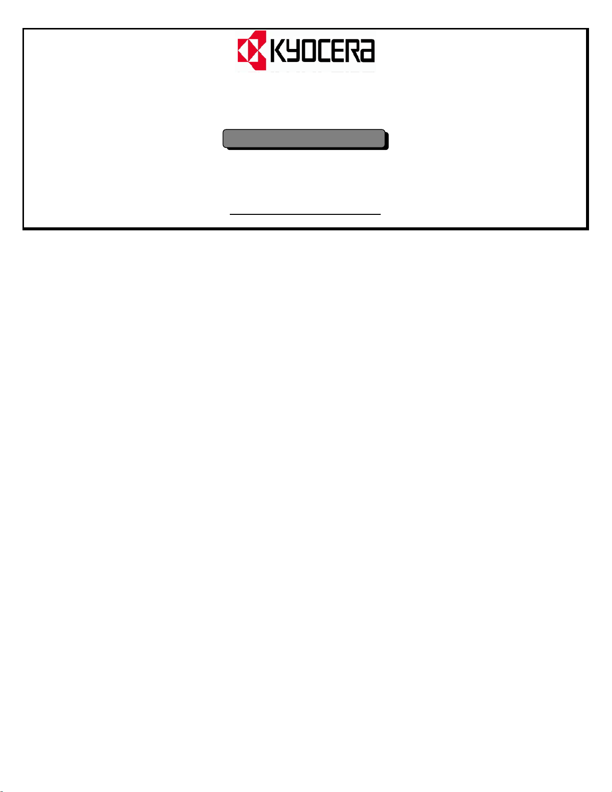
6. MODULE TILT ANGLE
Kyocera solar modules produce the most power when they are pointed directly at the sun. For installations where the
solar modules are attached to a permanent structure, the solar modules should be tilted for optimum winter
performance. As a rule, if the system power production is adequate in the winter, it will be satisfactory during the rest of
the year. The module tilt angle is measured between the solar modules and the ground (Figure 1). Refer to Table 1 for
the recommended module tilt angle your site.
MODULE
SUNLIGHT
TILT ANGLE
HORIZONTAL
Table 1. Recommended Tilt Angles for Fixed
Systems—Based on Winter Performance
SITE
LATITUDE IN
DEGREES
0°TO 15
15°TO 25°
25°TO 30°
30°TO 35°
35°TO 40°
40°+
FIXED TILT ANGLE
15°
SAME AS LATITUDE
LATITUDE + 5°
LATITUDE + 10°
LATITUDE + 15°
LATITUDE + 20°
Figure 1. Module Tilt Angle
Page 3
7. INSTALLING KC MODULES
The frame of each module has 0.28”φ diameter (7 mm) mounting holes (Refer to Module Mounting Specifications).
These are used to secure the modules to the supporting structure. An example of a ground mounted structure is shown
in Figure 3. The four holes close to the corners of the module are most often used for attachment. Refer to the
Mounting Specification Specifications for the position of these holes. Clearance between the module frame and the
mounting surface may be required to prevent the junction box from touching the surface, and to circulate cooling air
around the back of the module. If the modules are to be installed on the roof or wall of a building, the standoff method
or the rack method is recommended.
STAND-OFF METHOD: The modules are supported
parallel to the surface of the building wall or roof.
Clearance between the module frames and surface of
the wall or roof is required to prevent wiring damage
and to allow air to circulate behind the module.
The recommended stand-off height is 4.5 in. (about 115
mm) If other mounting means are employed, this may
affect the Listing For Fire Class Ratings.
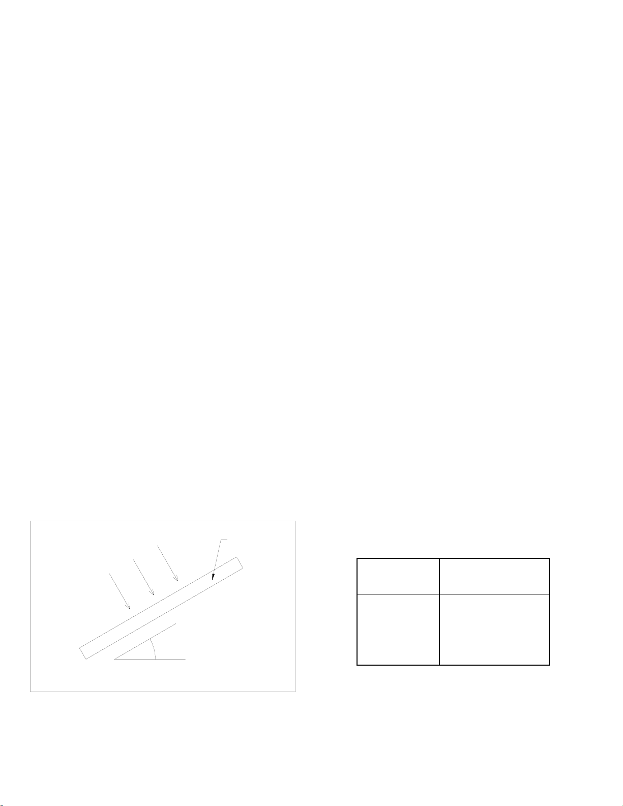
RACK: The supporting frame is used to mount
modules at correct tilt angles. The modules are not
designed for integral mounting as part of a roof or wall.
The mounting design may have an impact on the fire
resistance.
SUPPORT
LEGS
Figure 2. Basic Rack or Standoff Mounting Structure
MOUNTING HOLE
FOOT ANGLE
ARRAY FRAME
MODULE
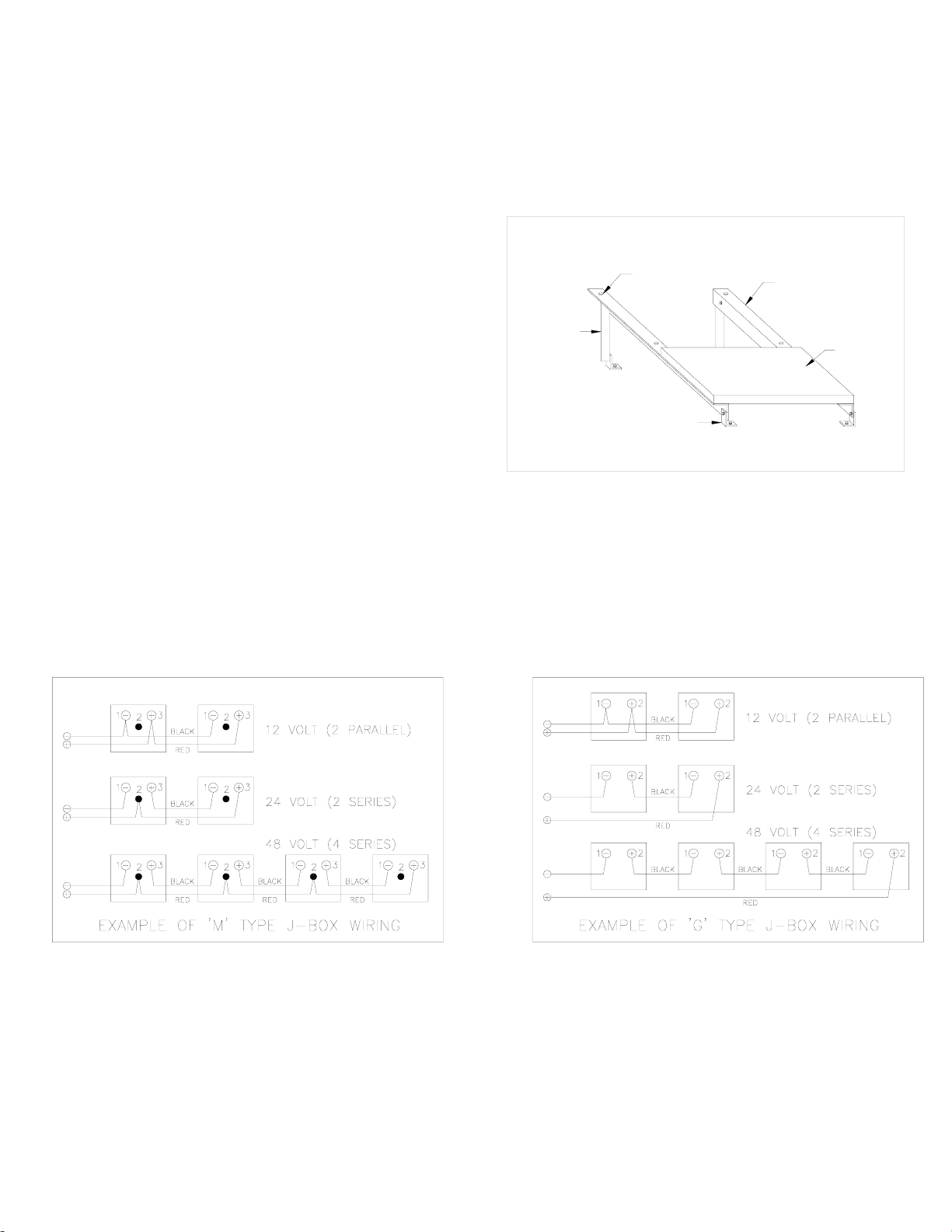
8. MODULE WIRING
As shown in Module Mounting Specifications, all of the KC modules utilize the Type G junction box except the KC-70,
KC-80 and KC-120-1 modules which utilize the Type M junction box (see J-box details). This junction box, located on
the back side of the module, is weatherproof and is designed to be used with standard wiring or conduit connections.
Kyocera recommends that all wiring and electrical connections comply with the 1999 National Electrical Code (NEC).
Bypass diodes and cable clamps are included with each module when shipped from the factory.
Figure 3. Standard Wiring Examples
To wire Kyocera modules:
A Determine the nominal system array voltage of your system. Each panel is equivalent to a 12 VDC nominal block.
Standard array voltages 12, 24 and 48 volt are shown as examples in Figure 3.
B. Open the "G" or "M" box cover by loosening the screws in the cover.
Page 4

C. The wire used to interconnect the solar modules
may be single or two conductor, from 14 AWG (2.08
2
) up to 10 AWG (5.26 mm2) gauge stranded
mm
copper wire, in a “SUNLIGHT RESISTANT” jacket
UF cable. This cable is suitable for applications
where wiring is exposed to the direct rays of the
sun. The maximum and minimum outer diameters
of the cable that may be used with the cable
connector are 8 mm and 6 mm respectively (Fig. 3).
D. Using a flat blade screwdriver, remove only the
appropriate "KNOCK-OUTS" from the sides of the
"G" or "M" box .
E. Route wires through the knock-outs and clamps in
the following steps (see
Figure 5):
a. Insert the nipple (1) of the clamp in a hole in the
junction box using lock nut (2).
b. Push the interconnect cable (3) through (1), (2)
and the cap (4).
c. Clamp the cable by tightening the cap (4).
F. Gently hand tighten the terminal screws with cross
tip (Phillips head) screwdriver. Do not overtighten,
as the terminal can be damaged.
G. The output wiring from the final module is generally
run to a separate array junction box. In commercial
system, this wiring from the array box to the next
component (i.e. fuse box. or charge regulator, etc.)
is generally run in conduit. The maximum electrical
rating of an acceptable series fuse is 4~12
amperes.
TERMINAL SCREW
SPRING WASHER
CABLE
CUP WASHER
Figure 4. Ring or Spade Terminal Connectors
Figure 5. Interconnect Cable Clamp
H. After checking that module wiring is correct, close and secure all the junction boxes. Use a Phillips head screw driver
to secure all screws on the junction box cover to ensure a waterproof seal.
9. GROUNDING
We recommend you attach all module frames to an earth ground. Attach a separate ground wire to one of the holes
marked ‘ground’ on the module frame with a screw and bonding or external tooth washer. This is to ensure positive
electrical contact with the frame. The racks must also be grounded unless they are mechanically connected by nuts
and bolts to the grounded modules.
Grounding is achieved by securing the array frame for both roof and field mounted applications. Additionally, the array
frame shall be grounded in accordance with NEC Art 250.
10. BLOCKING DIODES
Blocking diodes are typically placed between the battery and the PV module output to prevent battery discharge at
night. Kyocera modules are made of polycrystalline cells with high electrical “back flow” resistance to nighttime battery
discharging. As a result, KYOCERA modules do not contain a blocking diode when shipped from the factory. Most PV
charge regulators do have a nighttime disconnect feature, however.
11. BYPASS DIODES
Partial shading of an individual module in a 12 volt or higher source circuit string (i.e. two or more modules connected in
series) can cause a reverse voltage across the shaded module. Current is then forced through the shaded area by the
other modules.
Page 5

When a bypass diode is wired in parallel with the series string, the forced current will flow through the diode and bypass
the shaded module, thereby minimizing module heating and array current losses.
For 12-volt systems and higher: Each module junction box has a diagram illustrating the proper orientation of the
bypass diode installed between two of the terminal screws (Figure 11, Figure 12). When the solar modules are
connected as individual series strings first, and then these strings are connected in parallel, bypass diodes should be
used in each junction box. This is the simplest wiring arrangement for most installations.
Diodes that are used as bypass diodes must:
・ Have a Rated Average Forward Current [I
] Above maximum system current at highest module operating
F(AV)
temperature.
・ Have a Rated Repetitive Peak Reverse Voltage [V
] Above maximum system voltage at lowest module
RRM
operating temperature.
12. MAINTENANCE
Kyocera modules are designed for long life and require very little maintenance. Under most weather conditions, normal
rainfall is sufficient to keep the module glass surface clean. If dirt build-up becomes excessive, clean the glass surface
only with a soft cloth using mild detergent and water. USE CAUTION WHEN CLEANING THE BACK SURFACE OF
THE MODULE TO AVOID PENETRATING THE PVF SHEET. Modules that are mounted flat (0°tilt angle) should be
cleaned more often, as they will not "self clean" as effectively as modules mounted at a 15°tilt or greater. Once a
year, check the tightness of terminal screws and the general condition of the wiring. Also,
check to be sure that
mounting hardware is tight. Loose connections will result in a damaged module or array.
13. SPECIFICATIONS
The electrical and physical specifications can be found at the end of this document (Table 2).
NOTES
・ The electrical characteristics are within ±10 percent of indicated values of Isc, Voc, and Pmax under standard test
conditions (irradiance of 1KW/m
2
, AM 1.5 spectrum, and cell temperature of 25℃).
・ Under certain conditions, a photovoltaic module is likely to produce more current and / or voltage than reported at
standard test conditions. Accordingly, the values of Isc and Voc marked on this module should be multiplied by a
factor of 1.25 when determining component voltage ratings, conductor ampacities, fuse sizes, and sizes of
regulators which are connected to the PV output. Refer to Section 690-8 of the National Electrical Code for an
additional multiplying factor of 125 (80 per cent derating) which may also be applicable.
MANUFACTURED IN JAPAN BY KYOCERA CORPORATION
KSI GROUP
Kyocera Solar Inc. (Headquarters)
7812 East Acoma Drive, Scottsdale, AZ 85260, USA
Tel: (480) 948-8003 or (800) 223-9580
Fax: (480) 483-6431
www.kyocerasolar.com
Kyocera Solar Pty, Ltd.
36 Windorah St., Unit 6 Stafford 4053 Queensland, Australia
Tel: (61) 7-3856-5388
Fax: (61) 7-3856-5443
Kyocera Solar Argentina S.A.
Mejico 2145, 16400 Martinez Prov. de Buenos Aires Argentina
Tel: (54) 114-836-1040
Fax: (54) 114-836-0808
KFG GROUP
Kyocera Fineceramics GmBH
Fritz Müller Strasse 107, D-73730 Esslingen, Germany
Phone: (49) 711-9393-417
Fax: (49) 711-9393-450
www.kyocera.de/products/solar.htm
KAP GROUP
Kyocera Asia Pacific Singapore
Fritz Müller Strasse 107, D-73730 Esslingen, Germany
298 Tiong Bahru Road, #13-03/05 Tiong Bahru Plaza Singapore
168730
Tel: (65) 271-0500
Fax: (65) 271-0600
Kyocera Solar Do Brazil
Rua Mauricio da Costa Faria, 85
22780-280 – Recreio – Rio de Janeiro
Tel: (55) 2-1554-5554
Fax: (55) 2-1553-4894
Page 6

Table 2. Kyocera KC-Family Module Specifications
Electrical Characteristics:
Model Number KC-120-1 KC-80 KC-70 KC-60 KC-50 KC-45 KC-40 KC-35
Rated Power, Watts (Pmax) 120 80 70 60 50 45 40 35
Open circuit Voltage (Voc) 21.5 21.5 21.5 21.5 21.5 19.2 21.5 18.8
Short Circuit Current (Isc) 7.45 4.97 4.35 3.73 3.1 3.1 2.48 2.5
Voltage at Load (Vmp) 16.9 16.9 16.9 16.9 16.7 15 16.9 15
Current at Load (Imp) 7.1 4.73 4.14 3.55 3 3 2.34 2.33
Maximum System Voc 600 600 600 600 600 600 600 N/A
Factory Installed Bypass Diode (Qty) yes (6) yes (6) yes (6) yes (4) yes (4) yes (4) yes (4) yes (4)
Series Fuse Rating (Amps) 11 7 7 6 6 6 6 6
NOTE: The Electrical specifications are under test conditions of irradiance of 1kW/M2, Spectrum
o
of 1.5 air mass and cell temperature of 25
C
Physical Characteristics:
Model Number KC-120-1 KC-80 KC-70 KC-60 KC-50 KC-45 KC-40 KC-35
Length, Inches (mm) 56.1
(1425)
Width, Inches (mm) 25.7 (652) 25.7
38.4
(976)
(652)
34.1
(865)
25.7
(652)
29.6
(751)
25.7
(652)
25.2
(639)
25.7
(652)
22.6
(573)
25.7
(652)
20.7
(526)
25.7
(652)
18.5
(471)
25.7
(652)
Depth (frame, Inches (mm) 1.42 (36) 1.42 (36) 1.42 (36) 1.42 (36) 1.42 (36) 1.42 (36) 1.42 (36) 1.42 (36)
Depth (including j-box), inches (mm) 2.0 (52) 2.0 (52) 2.2 (56) 2.0 (52) 2.1 (54) 2.1 (54) 2.0 (52) 2.1 (54)
Weight, Pounds (kg) 23.6 (11.9) 21.2 (9.6) 15.4 (7.0) 13.2 (6.0) 11.0 (5.0) 9.9 (4.5) 9.9 (4.5) 8.8 (4.0)
Mounting Hole Diameter, inches (mm) * 0.28" (7) 0.28" (7) 0.28" (7) 0.28" (7) 0.28" (7) 0.28" (7) 0.28" (7) 0.28" (7)
*Note: See Module Mounting Specifications for Hole Location on Frame
Page 7

MODULE MOUNTING DIMENSIONS
DO NOT USE
DO NOT USE
KYOCERA KC−SERIES
MODULE MOUNTING SPECIFICATIONS
 Loading...