

Page 1

DP-420/PF-420
DF-420/JS-420
FAX System (R)
SERVICE
MANUAL
Published in May 2009
3MZSM060
First Edition
Page 2

CAUTION
RISK OF EXPLOSION IF BATTERY IS REPLACED BY AN INCORRECT TYPE. DISPOSE OF
USED BATTERIES ACCORDING TO THE INSTRUCTIONS.
It may be illegal to dispose of this battery into the municipal waste stream. Check with your local
solid waste officials for details in your area for proper disposal.
ATTENTION
IL Y A UN RISQUE D’EXPLOSION SI LA BATTERIE EST REMPLACEE PAR UN MODELE DE
TYPE INCORRECT. METTRE AU REBUT LES BATTERIES UTILISEES SELON LES INSTRUCTIONS DONNEES.
Il peut être illégal de jeter les batteries dans des eaux d’égout municipales. Vérifiez avec les fonctionnaires municipaux de votre région pour les détails concernant des déchets solides et une mise
au rebut appropriée.
Page 3

Revision history
Revision Date Replaced pages Remarks
Page 4

This page is intentionally left blank.
Page 5

Safety precautions
This booklet provides safety warnings and precautions for our service personnel to ensure the safety of
their customers, their machines as well as themselves during maintenance activities. Service personnel
are advised to read this booklet carefully to familiarize themselves with the warnings and precautions
described here before engaging in maintenance activities.
Page 6
Safety warnings and precautions
Various symbols are used to protect our service personnel and customers from physical danger and
to prevent damage to their property. These symbols are described below:
DANGER: High risk of serious bodily injury or death may result from insufficient attention to or incorrect
compliance with warning messages using this symbol.
WARNING: Serious bodily injury or death may result from insufficient attention to or incorrect compliance
with warning messages using this symbol.
CAUTION: Bodily injury or damage to property may result from insufficient attention to or incorrect
compliance with warning messages using this symbol.
Symbols
The triangle ( ) symbol indicates a warning including danger and caution. The specific point
of attention is shown inside the symbol.
General warning.
Warning of risk of electric shock.
Warning of high temperature.
indicates a prohibited action. The specific prohibition is shown inside the symbol.
General prohibited action.
Disassembly prohibited.
indicates that action is required. The specific action required is shown inside the symbol.
General action required.
Remove the power plug from the wall outlet.
Always ground the copier.
Page 7
1.Installation Precautions
WARNING
• Do not use a power supply with a voltage other than that specified. Avoid multiple connections to
one outlet: they may cause fire or electric shock. When using an extension cable, always check
that it is adequate for the rated current. .............................................................................................
• Connect the ground wire to a suitable grounding point. Not grounding the copier may cause fire or
electric shock. Connecting the earth wire to an object not approved for the purpose may cause
explosion or electric shock. Never connect the ground cable to any of the following: gas pipes,
lightning rods, ground cables for telephone lines and water pipes or faucets not approved by the
proper authorities. ............................................................................................................................
CAUTION:
• Do not place the copier on an infirm or angled surface: the copier may tip over, causing injury. .......
• Do not install the copier in a humid or dusty place. This may cause fire or electric shock. ................
• Do not install the copier near a radiator, heater, other heat source or near flammable material.
This may cause fire. .........................................................................................................................
• Allow sufficient space around the copier to allow the ventilation grills to keep the machine as cool
as possible. Insufficient ventilation may cause heat buildup and poor copying performance. ...........
• Always handle the machine by the correct locations when moving it. ...............................................
• Always use anti-toppling and locking devices on copiers so equipped. Failure to do this may cause
the copier to move unexpectedly or topple, leading to injury. ...........................................................
• Avoid inhaling toner or developer excessively. Protect the eyes. If toner or developer is accidentally ingested, drink a lot of water to dilute it in the stomach and obtain medical attention immediately. If it gets into the eyes, rinse immediately with copious amounts of water and obtain medical
attention. ......................................................................................................................................
• Advice customers that they must always follow the safety warnings and precautions in the copier’s
instruction handbook. .....................................................................................................................
Page 8
2.Precautions for Maintenance
WARNING
• Always remove the power plug from the wall outlet before starting machine disassembly. ...............
• Always follow the procedures for maintenance described in the service manual and other related
brochures. .......................................................................................................................................
• Under no circumstances attempt to bypass or disable safety features including safety mechanisms
and protective circuits. .....................................................................................................................
• Always use parts having the correct specifications. ..........................................................................
• Always use the thermostat or thermal fuse specified in the service manual or other related brochure when replacing them. Using a piece of wire, for example, could lead to fire or other serious
accident. ..........................................................................................................................................
• When the service manual or other serious brochure specifies a distance or gap for installation of a
part, always use the correct scale and measure carefully. ................................................................
• Always check that the copier is correctly connected to an outlet with a ground connection. .............
• Check that the power cable covering is free of damage. Check that the power plug is dust-free. If it
is dirty, clean it to remove the risk of fire or electric shock. ..............................................................
• Never attempt to disassemble the optical unit in machines using lasers. Leaking laser light may
damage eyesight. ...........................................................................................................................
• Handle the charger sections with care. They are charged to high potentials and may cause electric
shock if handled improperly. ............................................................................................................
CAUTION
• Wear safe clothing. If wearing loose clothing or accessories such as ties, make sure they are
safely secured so they will not be caught in rotating sections. ..........................................................
• Use utmost caution when working on a powered machine. Keep away from chains and belts. ........
• Handle the fixing section with care to avoid burns as it can be extremely hot. ..................................
• Check that the fixing unit thermistor, heat and press rollers are clean. Dirt on them can cause
abnormally high temperatures. ........................................................................................................
Page 9
• Do not remove the ozone filter, if any, from the copier except for routine replacement. ....................
• Do not pull on the AC power cord or connector wires on high-voltage components when removing
them; always hold the plug itself. .....................................................................................................
• Do not route the power cable where it may be stood on or trapped. If necessary, protect it with a
cable cover or other appropriate item. .............................................................................................
• Treat the ends of the wire carefully when installing a new charger wire to avoid electric leaks. ........
• Remove toner completely from electronic components. ...................................................................
• Run wire harnesses carefully so that wires will not be trapped or damaged. ....................................
• After maintenance, always check that all the parts, screws, connectors and wires that were
removed, have been refitted correctly. Special attention should be paid to any forgotten connector,
trapped wire and missing screws. ...................................................................................................
• Check that all the caution labels that should be present on the machine according to the instruction
handbook are clean and not peeling. Replace with new ones if necessary. ......................................
• Handle greases and solvents with care by following the instructions below: .....................................
· Use only a small amount of solvent at a time, being careful not to spill. Wipe spills off completely.
· Ventilate the room well while using grease or solvents.
· Allow applied solvents to evaporate completely before refitting the covers or turning the power
switch on.
· Always wash hands afterwards.
• Never dispose of toner or toner bottles in fire. Toner may cause sparks when exposed directly to
fire in a furnace, etc. .......................................................................................................................
• Should smoke be seen coming from the copier, remove the power plug from the wall outlet imme-
diately. ............................................................................................................................................
3.Miscellaneous
WARNING
• Never attempt to heat the drum or expose it to any organic solvents such as alcohol, other than the
specified refiner; it may generate toxic gas. .....................................................................................
Page 10

This page is intentionally left blank.
Page 11

DP-420
First Edition
Page 12

CONTENTS
1-1 Specifications
1-1-1 Specifications..........................................................................................................................................1-1-1
1-1-2 Parts names............................................................................................................................................1-1-2
1-1-3 Machine cross section ............................................................................................................................1-1-3
1-2 Installation
1-2-1 Installation environment ..........................................................................................................................1-2-1
1-2-2 Unpacking ...............................................................................................................................................1-2-2
(1) Unpacking .........................................................................................................................................1-2-2
(2) Removing the tapes and the spacer..................................................................................................1-2-3
1-3 Maintenance Mode
1-3-1 Maintenance mode (operation panel is a 7-segment type) .....................................................................1-3-1
(1) Executing a maintenance item ..........................................................................................................1-3-1
(2) Maintenance mode item list...............................................................................................................1-3-2
(3) Contents of maintenance mode items...............................................................................................1-3-3
1-3-2 Maintenance mode (operation panel is an LCD type)...........................................................................1-3-15
(1) Executing a maintenance item ........................................................................................................1-3-15
(2) Maintenance mode item list.............................................................................................................1-3-16
(3) Contents of maintenance mode items.............................................................................................1-3-17
3MX
1-4 Troubleshooting
1-4-1 Original misfeed detection ......................................................................................................................1-4-1
(1) Original misfeed indication ................................................................................................................1-4-1
(2) Original misfeed detection conditions................................................................................................1-4-1
(3) Paper misfeeds .................................................................................................................................1-4-3
1-4-2 Self-diagnosis .........................................................................................................................................1-4-4
(1) Self-diagnostic function (operation panel is a 7-segment type).........................................................1-4-4
(2) Self diagnostic codes (operation panel is a 7-segment type)............................................................1-4-4
(3) Self-diagnostic function (operation panel is an LCD type) ................................................................1-4-4
(4) Self diagnostic codes (operation panel is an LCD type)....................................................................1-4-4
1-4-3 Electric problems ....................................................................................................................................1-4-5
1-4-4 Mechanical problems ..............................................................................................................................1-4-6
1-5 Assembly and Disassembly
1-5-1 Precautions for assembly and disassembly............................................................................................1-5-1
(1) Precautions .......................................................................................................................................1-5-1
1-5-2 Original feed section ...............................................................................................................................1-5-2
(1) Detaching and refitting the DP forwarding pulley and DP feed pulley...............................................1-5-2
(2) Detaching and refitting the DP separation pad..................................................................................1-5-5
1-5-3 Image adjustment ...................................................................................................................................1-5-6
(1) Adjusting the angle of leading edge ..................................................................................................1-5-6
(2) Adjusting the angle of trailing edge ...................................................................................................1-5-8
2-1 Mechanical construction
2-1-1 Mechanical construction .........................................................................................................................2-1-1
(1) Operation of original switchback .......................................................................................................2-1-3
2-2 Electrical Parts Layout
2-2-1 Electrical parts layout..............................................................................................................................2-2-1
(1) PWBs ................................................................................................................................................2-2-1
(2) Switches and sensors .......................................................................................................................2-2-2
(3) Motors ...............................................................................................................................................2-2-3
(4) Solenoids...........................................................................................................................................2-2-4
2-3 Operation of the PWBs
2-3-1 DP main PWB .........................................................................................................................................2-3-1
Page 13

3MX
2-4 Appendixes
List of maintenance parts........................................................................................................................2-4-1
Periodic maintenance procedures ..........................................................................................................2-4-2
Wiring diagram........................................................................................................................................2-4-4
Page 14

1-1 Specifications
1-1-1 Specifications
Type................................................Duplex sheet-through document feeder
Original feed method ......................Automatic feed
Original weight ................................Single-sided original mode: 45 to 160 g/m
Double-sided original mode: 50 to 120 g/m
Original type....................................Sheet originals
Original size .................................... A3 to A5R/Ledger to StatementR
Original No. of sheets .....................50 sheets or less (50 to 80 g/m
Mixed original sizes: 30 sheets or less (50 to 80 g/m2)
Original scanning speed .................53.5 to 107 mm/s
Power source..................................Electrically connected to the machine
Dimensions .....................................559 (W) x 487 (D) x 131 (H) mm
22" (W) x 19
3/16" (D) x 5 3/16" (H)
Weight.............................................7 kg/15.4 lbs or less
NOTE: These specifications are subject to change without notice.
2
)
3MX
2
2
1-1-1
Page 15
3MX
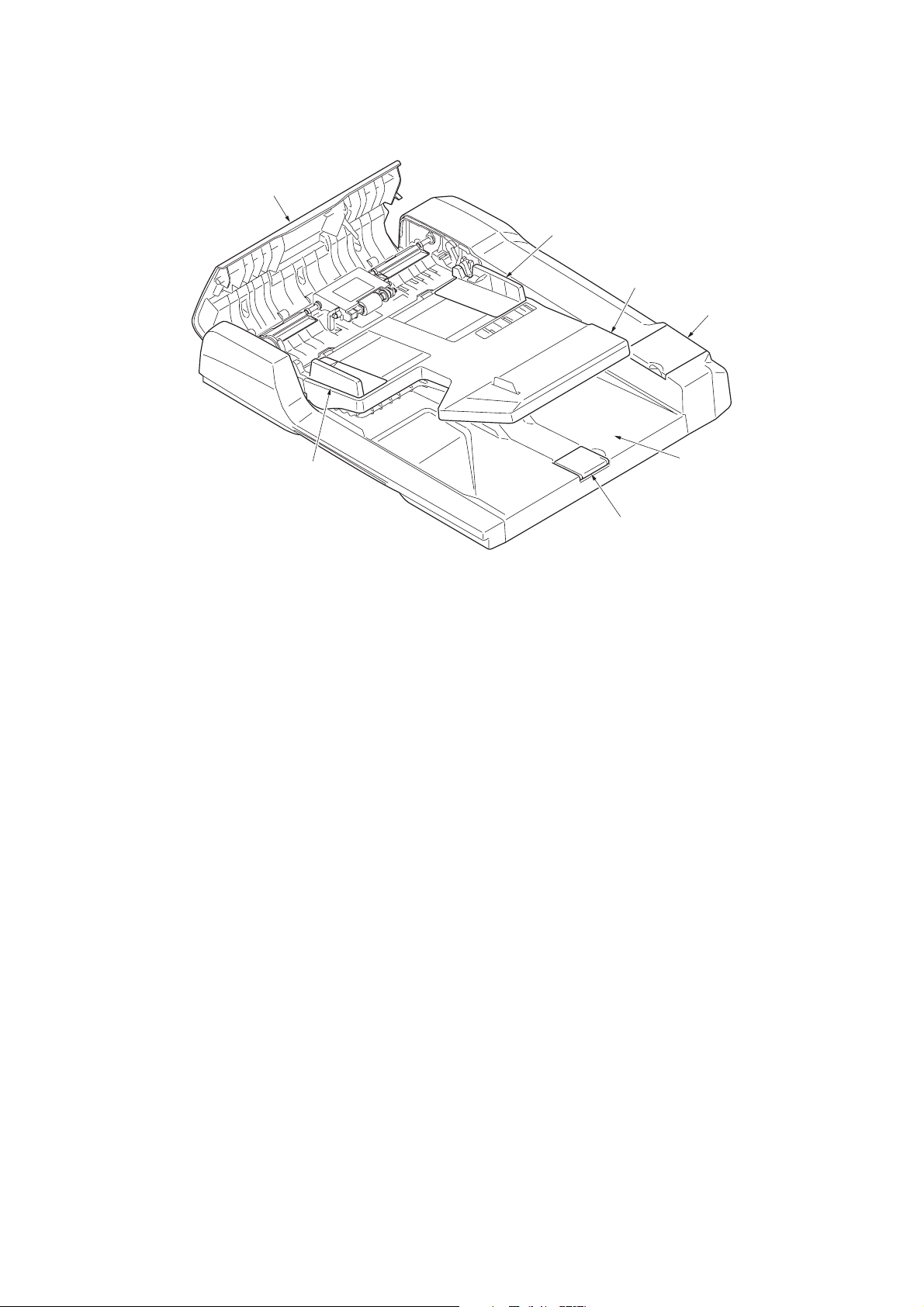
1-1-2 Parts names
4
2
1
6
2
Figure 1-1-1
1. Original table
2. Original width guides
3. Original eject table
4. Document processor top cover
5. Original stopper
6. Cleaning cloth compartment
3
5
1-1-2
Page 16
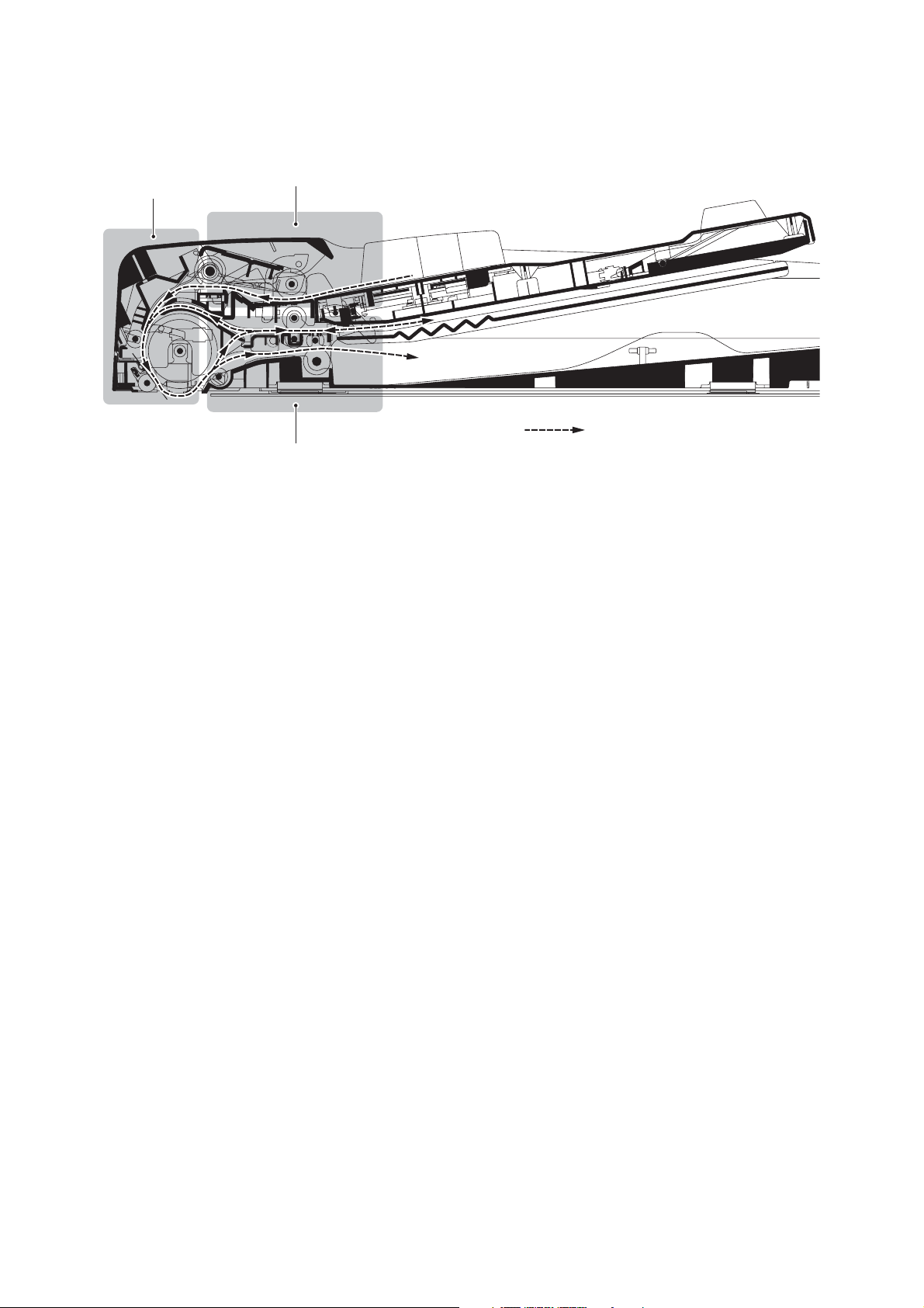
1-1-3 Machine cross section
3MX
2
1
Original path
3
Figure 1-1-2 Machine cross section
1. Original feed section
2. Original conveying section
3. Original switchback section
1-1-3
Page 17

3MX
This page is intentionally left blank.
1-1-4
Page 18

3MX
1-2 Installation
1-2-1 Installation environment
Installation location (Be based on the machine establishment place.)
Avoid direct sunlight or bright lighting. Ensure that the photoconductor will not be exposed to direct sunlight or other strong
light when removing paper jams.
Avoid locations subject to high temperature and high humidity or low temperature and low humidity; an abrupt change in
the environmental temperature; and cool or hot, direct air.
Avoid places subject to dust and vibrations.
Choose a surface capable of supporting the weight of the machine.
Place the machine on a level surface (maximum allowance inclination: 1
Avoid air-borne substances that may adversely affect the machine or degrade the photoconductor, such as mercury, acidic
of alkaline vapors, inorganic gasses, NOx, SOx gases and chlorine-based organic solvents.
Select a well-ventilated location.
°).
1-2-1
Page 19
3MX
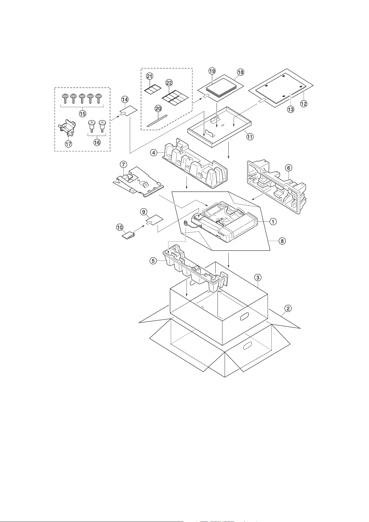
1-2-2 Unpacking
(1) Unpacking
1. Document processor
2. Outer case
3. Inner case
4. Rear upper pad
5. Rear lower pad
6. Front pad
7. Spacer
8. Plastic sheet
Caution: See the Installation Guide for installation.
1-2-2
Figure 1-2-1 Unpacking
9. Plastic bag
10. Cleaning cloth
11. Tray spacer
12. Plastic bag
13. Original mat
14. Plastic bag
15. M4 x 14 screws
16. Pins
17. Angle adjusting plate
18. Plastic bag
19. Installation guide
20. Film
21. Label A
22. Label B (220 V - 240 V
specifications only)
Page 20
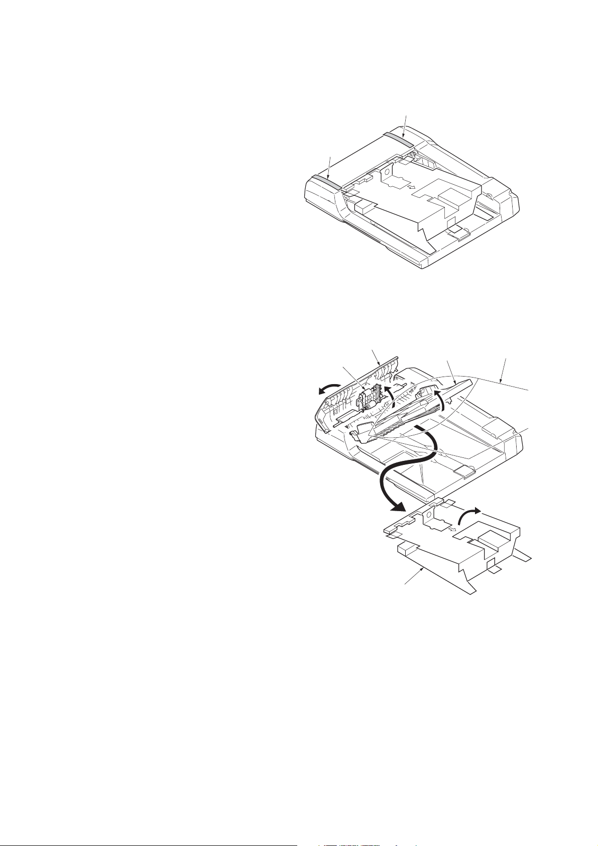
(2) Removing the tapes and the spacer
3MX
Procedure
1. Remove two tapes.
2. Open the document processor top cover.
3. Raise the DP feed pulley unit.
4. Open the spacer.
5. Raise the original table.
6. Remove the spacer.
7. Remove the plastic bag.
Ta pe
Document processor
top cover
DP feed pulley unit
Ta pe
Figure 1-2-2
Original table
Plastic bag
Spacer
Figure 1-2-3
1-2-3
Page 21

3MX
This page is intentionally left blank.
1-2-4
Page 22
1-3 Maintenance Mode
1-3-1 Maintenance mode (operation panel is a 7-segment type)
The machine is equipped with a maintenance function which can be used to maintain and service the machine.
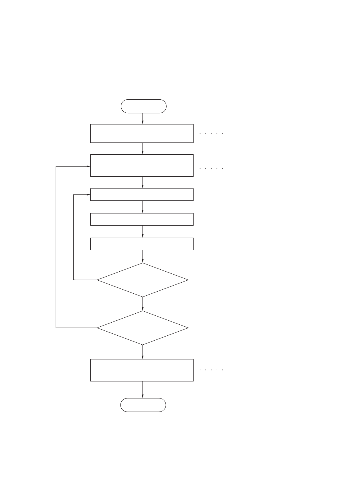
(1) Executing a maintenance item
Start
3MX
Yes
Enter “10871087” using
the numeric keys.
Enter the maintenance item
number using the zoom
+/- keys or numeric keys.
Press the start key.
The selected maintenance item is run.
Press the stop/clear key.
Repeat the same
maintenance item?
Maintenance mode is entered.
The maintenance item is
selected.
Yes
No
Run another maintenance
item?
No
Enter “001” using the
or numeric keys
+/- keys
zoom
and press the start key.
End
Maintenance mode is exited.
1-3-1
Page 23

3MX
(2) Maintenance mode item list
Section
Item
No.
Content of maintenance item
Initial
setting*
General U019 Displaying the ROM version -
Optical U068 Adjusting the scanning position for originals from the DP 0
U070 Adjusting the DP magnification 0/0
U071 Adjusting the DP scanning timing 0/0/0/0
U072 Adjusting the DP center line 0/0
U074 Adjusting the DP input light luminosity 1
U076 Adjusting the DP automatically -
U087 Setting DP reading position modification operation ON/35
Operation
panel and
support
equipment
Image
U203 Checking DP operation -
U243 Checking the operation of the DP motors -
U244 Checking the DP switches -
U404 Adjusting margins for scanning an original from the DP 2.0/3.0/2.0/2.0
processing
Other U905 Checking/clearing counts by optional devices -
U942 Setting of deflection for feeding from DP 0/0
*1
*1
*1
*1
*1
*1
*1
*1
*Initial setting for executing U020, *1: The item initialized for executing U020, *2: The item initialized for executing U021
1-3-2
Page 24
(3) Contents of maintenance mode items
3MX
Maintenance
item No.
U019
Description
Displaying the ROM version
Description
Displays the part number of the ROM fitted to each board.
Purpose
To check the part number or to decide if the ROM version is new from the last digit of the number.
Method
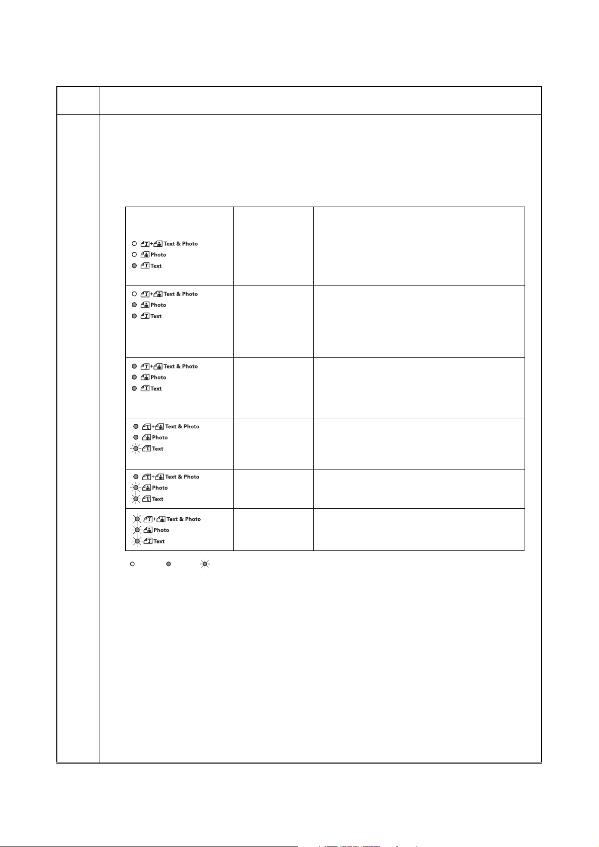
1. Press the start key.
2. Select the item to be displayed using the image mode selection key and exposure adjustment keys.
Image mode LEDs
Exposure
indicator
Exp. 1 (lit)
Exp. 2 (lit)
Exp. 3 (lit)
Exp. 4 (lit)
Exp. 1 (lit)
Exp. 2 (lit)
Exp. 3 (lit)
Exp. 4 (lit)
Exp. 5 (lit)
Exp. 1 (flashing)
Exp. 1 (lit)
Exp. 2 (lit)
Exp. 3 (lit)
Exp. 4 (lit)
Exp. 5 (lit)
Copy quantity display
“A” Part Code: Main PWB
Change history of the main PWB
Number of the main ROM
Number of the main ROM sub
“E” Part Code: Engine PWB
Change history of the engine PWB
Number of the engine ROM
Number of the engine ROM sub
Change history of the engine PWB BOOT
Number of the engine PWB BOOT
“L” Part Code: Language
Change history of the standard language
Number of the standard language ROM
Change history of the optional language
Number of the optional language ROM
Exp. 1 (lit)
Exp. 2 (lit)
Exp. 3 (lit)
Exp. 4 (lit)
Exp. 1 (lit)
Exp. 2 (lit)
Exp. 1 (lit)
Exp. 2 (lit)
Exp. 3 (lit)
: Off, : On, : Flashing
When the optional equipment is not installed, [non] is displayed.
Completion
Press the stop/clear key. The screen for selecting a maintenance item No. is displayed.
“C” Part Code: Cassette
Number of the optional first paper feeder ROM
Number of the optional second paper feeder ROM
Number of the optional third paper feeder ROM
“d” Part Code: DP
Number of the DP ROM
“P” Part Code: Printer
Change history of the optional printer
Number of the optional printer ROM
1-3-3
Page 25

3MX
Maintenance
item No.
U068
Description
Adjusting the scanning position for originals from the DP
Description
Adjusts the position for scanning originals from the DP.
Purpose
Used when the image fogging occurs because the scanning position is not proper when the DP is used. Run
U071 to adjust the timing of DP leading edge when the scanning position is changed.
Setting
1. Press the start key.
2. Change the setting using the zoom +/- keys.
Description Setting range Initial setting Change in value per step
Scanning position -17 to 17 0 0.17 mm
Increasing the value moves the image backward, and decreasing it moves the image forward.
Supplement
While this maintenance item is being executed, copying from an original is available in interrupt copying mode
(which is activated by pressing the interrupt key).
Completion
Press the stop/clear key. The screen for selecting a maintenance item No. is displayed.
1-3-4
Page 26
3MX
Maintenance
item No.
U070
Description
Adjusting the DP magnification
Description
Adjusts the DP original scanning speed.
Purpose
Make the adjustment if the magnification is incorrect in the auxiliary scanning direction when the optional DP
is used.
Adjustment
1. Press the start key.
2. Select the item using the exposure adjustment keys.
Display Description Setting
range
Exp. 1 Magnification in the auxiliary scan-
-25 to 25 0 0.2 mm
Initial
setting
Change in
value per step
ning direction (first page)
Exp. 2 Magnification in the auxiliary scan-
-25 to 25 0 0.2 mm
ning direction (second page)
3. Press the interrupt key.
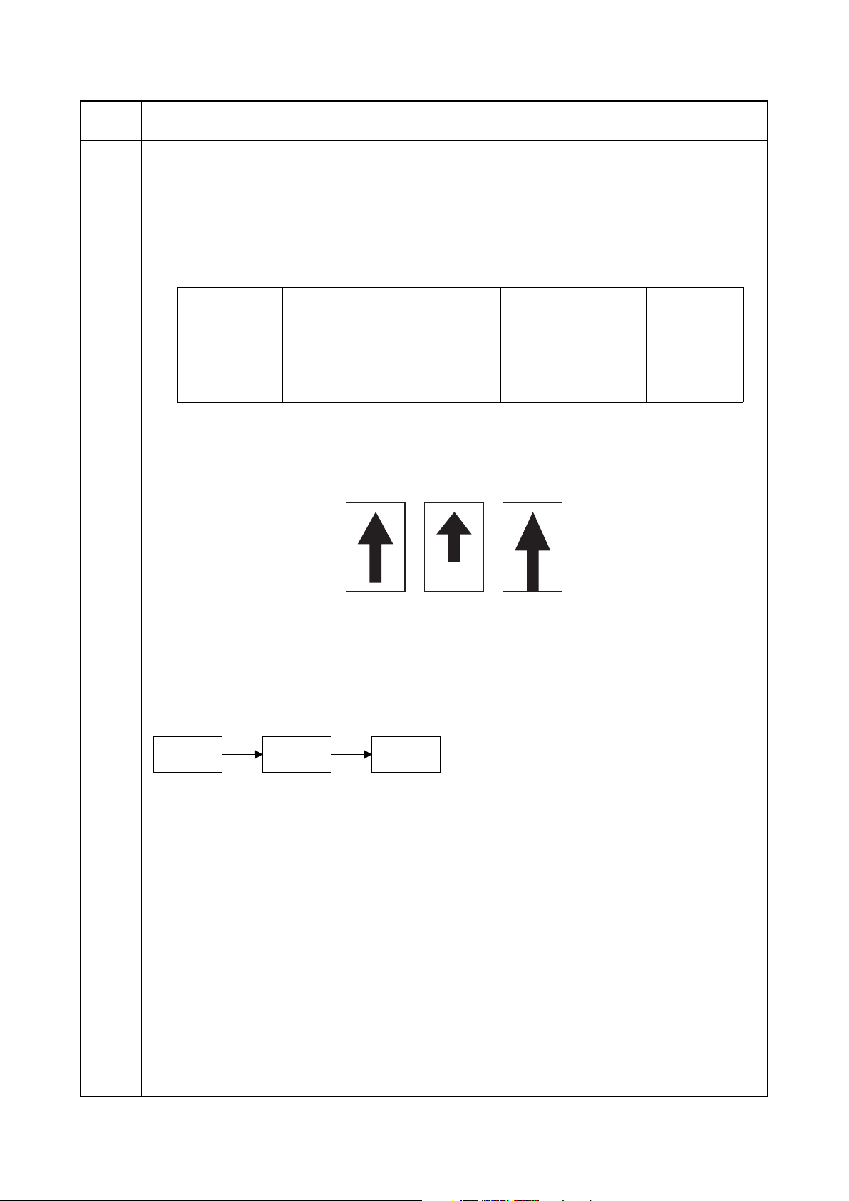
4. Place an original on the DP and press the start key to make a test copy.
5. Change the setting value using the zoom +/- keys.
For copy example 1, increase the value.
For copy example 2, decrease the value.
Original Copy
example 1
Copy
example 2
Figure 1-3-1
6. Press the start key. The value is set.
Caution
Check the copy image after the adjustment. If the image is still incorrect, perform the following adjustments in
maintenance mode.
U070
U071
(P.1-3-6)
U404
(P.1-3-13)
Completion
Press the stop/clear key. The screen for selecting a maintenance item No. is displayed.
1-3-5
Page 27
3MX
Maintenance
item No.
U071
Description
Adjusting the DP scanning timing
Description
Adjusts the DP original scanning timing.
Purpose
Make the adjustment if there is a regular error between the leading or trailing edges of the original and the
copy image when the optional DP is used.
Method
1. Press the start key.
2. Select the item using the exposure adjustment keys.
Exposure
indicator
Exp. 1 DP leading edge registration
Description Setting
range
-32 to 32 0 0.2 mm
Initial
setting
Change in
value per step
(first side)
Exp. 2 DP trailing edge registration
-42 to 32 0 0.2 mm
(first side)
Exp. 3 DP leading edge registration
-32 to 32 0 0.2 mm
(second side)
Exp. 4 DP trailing edge registration
-42 to 32 0 0.2 mm
(second side)
3. Press the interrupt key.
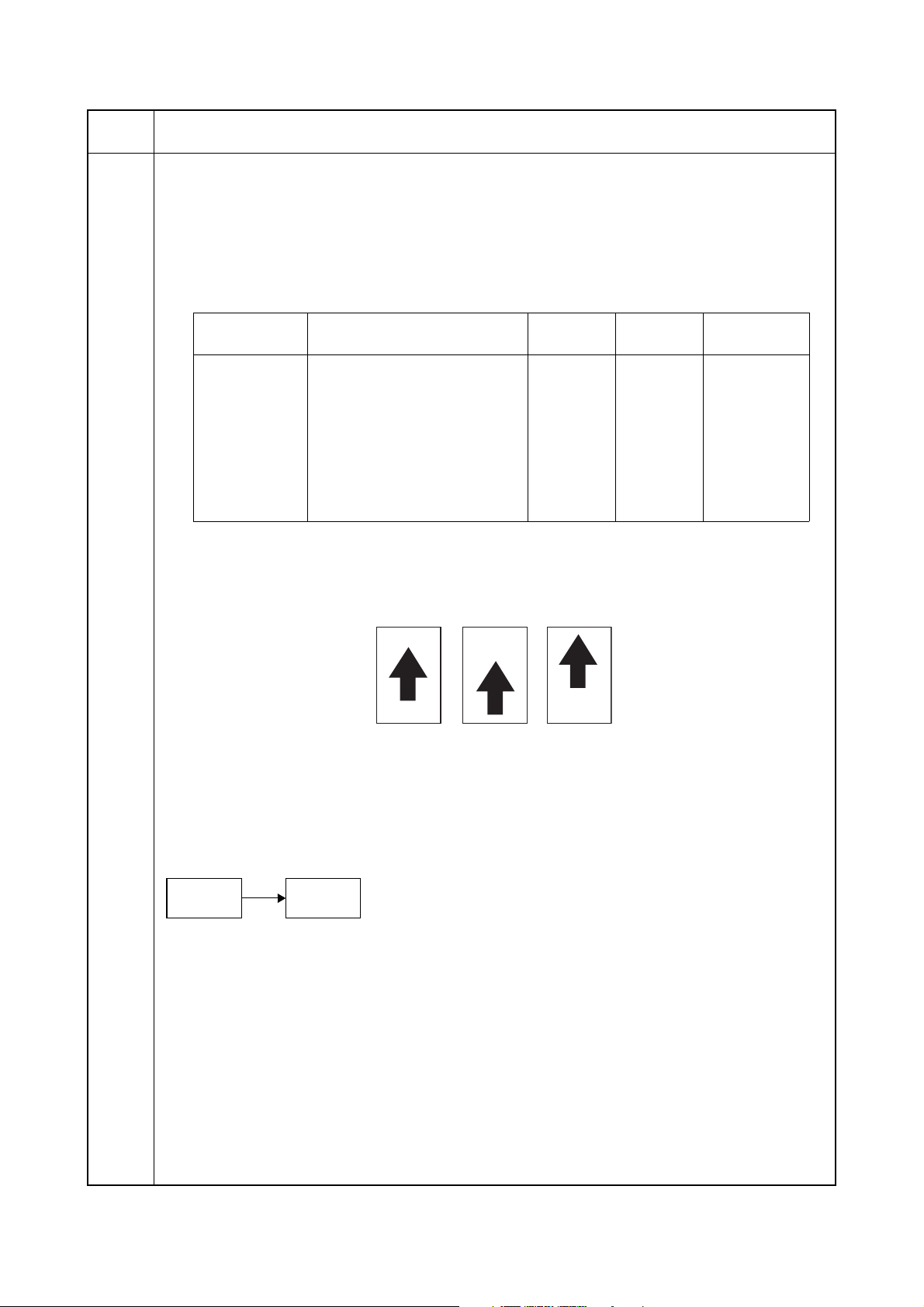
4. Place an original on the DP and press the start key to make a test copy.
5. Change the setting value using the zoom +/- keys.
For copy example 1, decrease the value of exp.1.
For copy example 2, increase the value of exp.1.
Original Copy
example 1
Copy
example 2
Figure 1-3-2
6. Press the start key. The value is set.
Caution
Check the copy image after the adjustment. If the image is still incorrect, perform the following adjustments in
maintenance mode.
U071
U404
(P.1-3-13)
Completion
Press the stop/clear key. The screen for selecting a maintenance item No. is displayed.
1-3-6
Page 28

3MX
Maintenance
item No.
U072
Description
Adjusting the DP center line
Description
Adjusts the scanning start position for the DP original.
Purpose
Make the adjustment if there is a regular error between the centers of the original and the copy image when
the optional DP is used.
Adjustment
1. Press the start key.
2. Select the item using the exposure adjustment keys.
Exposure
indicator
Description
Setting
range
Initial
setting
Change in
value per step
Exp. 1 DP center line (first side) -6.6 to 6.6 0 0.15 mm
Exp. 2 DP center line (second side) -3.0 to 3.0 0 0.15 mm
3. Press the interrupt key.
4. Place an original on the DP and press the start key to make a test copy.
5. Change the setting value using the zoom +/- keys.
For copy example 1, increase the value.
For copy example 2, decrease the value.
Original Copy
example 1
Copy
example 2
Figure 1-3-3
6. Press the start key. The value is set.
Caution
Check the copy image after the adjustment. If the image is still incorrect, perform the following adjustments in
maintenance mode.
U072
U404
(P.1-3-13)
Completion
Press the stop/clear key. The screen for selecting a maintenance item No. is displayed.
1-3-7
Page 29

3MX
Maintenance
item No.
U074
Description
Adjusting the DP input light luminosity
Description
Adjusts the luminosity of the exposure lamp for scanning originals from the DP.
Purpose
Used if the exposure amount differs significantly between when scanning an original on the platen and when
scanning an original from the DP.
Setting
1. Press the start key.
2. Change the setting using the zoom +/- keys.
Description Setting range Initial setting
DP input light luminosity 0 to 8 1
Increasing the setting makes the luminosity higher, and decreasing it makes the luminosity lower.
3. Press the start key. The value is set.
Supplement
While this maintenance item is being executed, copying from an original is available in interrupt copying mode
(which is activated by pressing the interrupt key).
Completion
Press the stop/clear key. The screen for selecting a maintenance item No. is displayed.
1-3-8
Page 30
3MX
Maintenance
item No.
U076
Description
Adjusting the DP automatically
Description
Uses a specified original and automatically adjusts the following items in the DP scanning section.
Adjusting the DP magnification (U070)
Adjusting the DP scanning timing (U071)
Adjusting the DP center line (U072)
When you run this maintenance mode, the preset values of U070, U071 and U072 will also be updated.
Purpose
To perform automatic adjustment of various items in the DP scanning section.
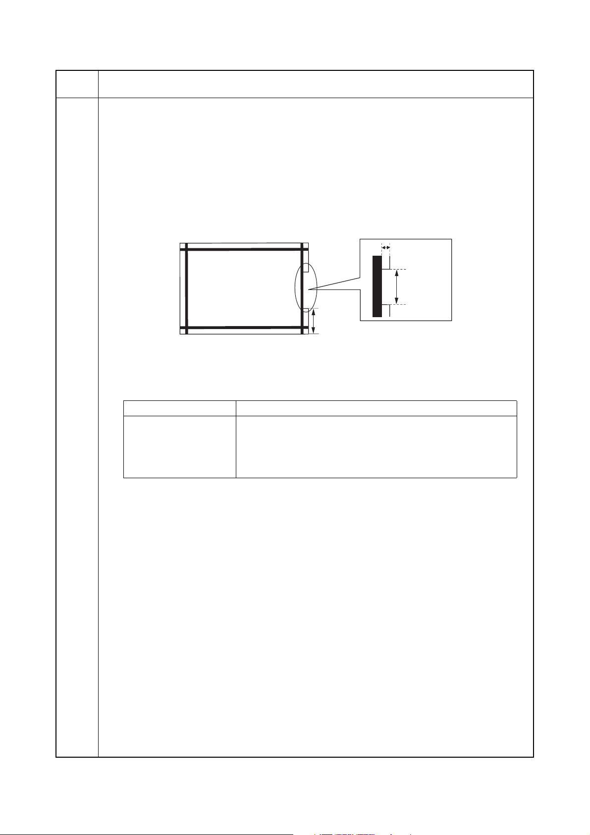
Method
1. Set a specified original (P/N: 302AC68243) in the DP.
Cut the trailing edge of the original.
F
5 mm
149 ± 1 mm
R
74 ± 1 mm
Figure 1-3-4
2. Press the start key. "on" appears.
3. Press the start key. Auto adjustment starts. When adjustment is complete, "Gd" appears.
4. Display each setting value after adjustment using the exposure adjustment keys.
Exposure indicator Description
Exp. 1 Execution result
Exp. 2 DP scanning timing
Exp. 3 DP center line
Exp. 4 DP magnification
If a problem occurs during auto adjustment, "nG" is displayed and operation stops. Determine the details
of the problem and either repeat the procedure from the beginning, or adjust the remaining items manually by running the corresponding maintenance items.
Completion
Press the stop/clear key after auto adjustment is complete.The screen for selecting a maintenance item No. is
displayed.
If the stop/clear key is pressed during auto adjustment, adjustment stops and no settings are changed.
1-3-9
Page 31

3MX
Maintenance
item No.
U087
Description
Setting DP reading position modification operation
Description
The presence or absence of dust is determined by comparing the scan data of the original trailing edge and
that taken after the original is conveyed past the DP original scanning position. If dust is identified, the DP
original scanning position is adjusted for the following originals.
Purpose
When using DP, to solve the problem when black lines occurs due to the dust with respect to original reading
position.
Setting
1. Press the start key.
2. Select the item to be set using the exposure adjustment keys.
Exposure indicator Description
Exp. 1 Setting the mode on/off
Exp. 2 Setting the reference data for identifying dust
Setting the mode on/off
1. Select "on" or "oFF" using the zoom +/- keys.
Display Description
on DP scanning position adjust mode on
oFF DP scanning position adjust mode off
Initial setting: on
2. Press the start key. The setting is set.
Setting the reference data for identifying dust
Available only when the mode is turned on.
1. Change the setting using the zoom +/- keys.
Description Setting range Initial setting
Minimum density to be regarded as dust 10 to 95 35
Example
The figure indicates the density in 256 levels of gray (0: white, 255: black). When the setting is 35, data
of the level of 35 or higher is regarded as dust and data of lower level is regarded as the background
(scan data taken when there is no original).
2. Press the start key. The value is set.
Completion
Press the stop/clear key. The screen for selecting a maintenance item No. is displayed.
1-3-10
Page 32

3MX
Maintenance
item No.
U203
U243
Description
Checking DP operation
Description
Simulates the original conveying operation separately in the DP.
Purpose
To check the DP operation.
Method
1. Press the start key.
2. Place an original on the DP if running this simulation with paper.
3. Select the item to be operated using the exposure adjustment keys.
Exposure indicator Display Motor
Exp. 1 d-P With paper
Exp. 2 d-n Without paper (continuous operation)
Exp. 3 dp2 With paper (duplex mode)
Exp. 4 dn2 Without paper (duplex mode)
4. Press the start key. The operation starts.
5. To stop continuous operation, press the stop/clear key.
Completion
Press the stop/clear key when the operation stops. The screen for selecting a maintenance item No. is displayed.
Checking the operation of the DP motors
Description
Turns the motors or solenoids in the optional DP on.
Purpose
To check the operation of the DP motors or solenoids.
Method
1. Press the start key.
2. Select the motor or solenoid to be operated using the exposure adjustment keys.
3. Press the start key. The operation starts.
Exposure indicator Display Motor
Exp. 1 F-0 Original feed motor (OFM)
Exp. 2 C-0 Original conveying motor (OCM)
Exp. 3 r-0 Original switchback motor (OSBM)
Exp. 4 b-S Switchback feedshift solenoid (SBFSSOL)
Exp. 5 P-S Switchback pressure solenoid (SBPSOL)
4. To turn each motor off, press the stop/clear key.
Completion
Press the stop/clear key when operation stops. The screen for selecting a maintenance item No. is displayed.
1-3-11
Page 33

3MX
Maintenance
item No.
U244
Description
Checking the DP switches
Description
Displays the status of the respective switches in the DP.
Purpose
To check if respective switches in the DP operate correctly.
Method
1. Press the start key.
2. Turn each switch on and off manually to check the status. When the on-status of a switch is detected,
the LEDs on the operation panel corresponding to the operated switch lights.
LEDs Switch
Auto Exp. Original set switch (OSSW)
Text & Photo DP timing switch (DPTSW)
Photo Original detection switch (ODSW)
Text DP original cover switch (DPOCSW)
EcoPrint Original switchback switch (OSBSW)
Program Original size length switch (OSLSW)
Completion
Press the stop/clear key. The screen for selecting a maintenance item No. is displayed.
1-3-12
Page 34

3MX
Maintenance
item No.
U404
Description
Adjusting margins for scanning an original from the DP
Description
Adjusts margins for scanning the original from the DP.
Purpose
Make the adjustment if margins are incorrect when the optional DP is used.
Caution
Before making this adjustment, ensure that the following adjustments have been made in maintenance mode.
(See the service manual
U402
for the machine.))
(See the service manual
U403
for the machine.)
U404
Adjustment
1. Press the start key.
2. Select the item using the exposure adjustment keys.
Exposure
indicator
Description
Setting
range
Initial
setting
Change in
value per step
Exp. 1 Left margin 0.0 to 10.0 2.0 0.5 mm
Exp. 2 Leading edge margin 0.0 to 10.0 3.0 0.5 mm
Exp. 3 Right margin 0.0 to 10.0 2.0 0.5 mm
Exp. 4 Trailing edge margin 0.0 to 10.0 2.0 0.5 mm
3. Press the interrupt key.
4. Place an original on the DP and press the start key to make a test copy.
5. Change the setting value using the zoom +/- keys.
Increasing the value makes the margin wider, and decreasing it makes the margin narrower.
Leading edge margin
(3.0±2.5 mm)
Left margin
(2.5+1.5/-2.0 mm)
Trailing edge margin
(3.0±2.5 mm)
Right margin
(2.5+1.5/-2.0 mm)
Figure 1-3-5
6. Press the start key. The value is set.
Completion
Press the stop/clear key. The screen for selecting a maintenance item No. is displayed.
1-3-13
Page 35

3MX
Maintenance
item No.
U905
U942
Description
Checking/clearing counts by optional devices
Description
Displays the counts of DP or finisher.
Purpose
To check the use of DP and finisher.
Method
1. Press the start key.
2. Select the count (group No.) to be checked using the image mode selection key.
3. Select the item using the exposure adjustment keys.
Image mode LED
(group No.)
1 Exp. 1
2 Exp. 1
: Off, : On
Completion
Press the stop/clear key. The screen for selecting a maintenance item No. is displayed.
Setting of deflection for feeding from DP
Description
Adjusts the deflection generated when the DP is used.
Purpose
Use this mode if an original non-feed jam, oblique feed or wrinkling of original occurs when the DP is used.
Setting
1. Press the start key.
2. Select the item using the exposure adjustment keys.
Exposure
indicator
Exp. 1 Original feed motor (OFM)
Exp. 2 Original switchback motor (OSBM)
3. Press the interrupt key.
4. Place an original on the DP and press the start key to make a test copy.
5. Change the setting value using the zoom +/- keys.
The greater the value, the larger the amount of slack; the smaller the value, the smaller the amount of
slack.
If an original non-feed jam or oblique feed occurs, increase the setting value. If wrinkling of original
occurs, decrease the value.
6. Press the start key. The value is set.
Completion
Press the stop/clear key. The screen for selecting a maintenance item No. is displayed.
Description Setting range Initial setting
(in simplex feed)
(in duplex feed)
Exposure
indicator
Exp. 2
Exp. 2
Copy quantity display (count value)
First 3 digits of the no. of single-sided originals
that has passed through the DP
Last 3 digits of the no. of single-sided originals
that has passed through the DP
First 3 digits of the no. of double-sided originals
that has passed through the DP
Last 3 digits of the no. of double-sided originals
that has passed through the DP
-10 to 20 0
-10 to 20 0
1-3-14
Page 36

1-3-2 Maintenance mode (operation panel is an LCD type)
The machine is equipped with a maintenance function which can be used to maintain and service the machine.
(1) Executing a maintenance item
Start
3MX
Yes
Enter 10871087 using
the numeric keys.
Enter the maintenance item
number using the cursor up/down keys
or numeric keys.
Press the start key.
The selected maintenance item is run.
Press the stop/clear key.
Repeat the same
maintenance item?
Maintenance mode is entered.
The maintenance item is
selected.
Yes
No
Run another maintenance
item?
No
Enter 001 using the cursor
up/down keys or numeric keys
and press the start key.
End
Maintenance mode is exited.
1-3-15
Page 37

3MX
(2) Maintenance mode item list
Section
Item
No.
Content of maintenance item
Initial
setting*
General U019 Displaying the ROM version -
Optical U068 Adjusting the scanning position for originals from the DP 0
U070 Adjusting the DP magnification 0/0
U071 Adjusting the DP scanning timing 0/0/0/0
U072 Adjusting the DP center line 0/0/0
U074 Adjusting the DP input light luminosity 0
U076 Executing DP automatic adjustment -
U087 Setting DP reading position modification operation ON/35
Operation
panel and
support
equipment
U203 Checking DP operation -
U243 Checking the operation of the DP motors -
U244 Checking the DP switches -
Mode setting U326 Setting the black line cleaning indication ON
Image
U404 Adjusting margins for scanning an original from the DP 2.0/3.0/2.0/2.0
processing
Other U905 Checking counts by optional devices -
U942 Setting of deflection for feeding from DP 0/0
*1
*1
*1
*1
*1
*1
*1,*2
*1
*1
*Initial setting for executing U020, *1: The item initialized for executing U020, *2: The item initialized for executing U021
1-3-16
Page 38

(3) Contents of maintenance mode items
3MX
Maintenance
item No.
U019
Description
Displaying the ROM version
Description
Displays the part number of the ROM fitted to each PWB.
Purpose
To check the part number or to decide, if the newest version of ROM is installed.
Method
1. Press the start key. The ROM version are displayed.
2. Change the screen using the cursor up/down keys.
Display Description
MAIN Main ROM
ENGINE Engine ROM
LANG(St) Standard language ROM
LANG(Op) Optional language ROM
MAIN BOOT Boot of main ROM
PRINTER Printer ROM
NWS Optional network scanner ROM
DP DP ROM
FINISHER Optional built-in finisher ROM
CASS2 Optional first paper feeder ROM (standard for 22 ppm model)
CASS3 Optional second paper feeder ROM
CASS4 Optional third paper feeder ROM
U068
Completion
Press the stop/clear key. The screen for selecting a maintenance item No. is displayed.
Adjusting the scanning position for originals from the DP
Description
Adjusts the position for scanning originals from the DP.
Purpose
Used when the image fogging occurs because the scanning position is not proper when the DP is used. Run
U071 to adjust the timing of DP leading edge when the scanning position is changed.
Setting
1. Press the start key.
2. Change the setting using the cursor left/right keys.
Description Setting
range
Starting position adjustment forscanning originals -17 to 17 0 0.17 mm
Increasing the value moves the image backward, and decreasing it moves the image forward.
3. Press the start key. The value is set.
Supplement
While this maintenance item is being executed, copying from an original is available in interrupt copying mode
(which is activated by pressing the interrupt key).
Completion
Press the stop/clear key. The screen for selecting a maintenance item No. is displayed.
Initial
setting
Change in
value per step
1-3-17
Page 39

3MX
Maintenance
item No.
U070
Description
Adjusting the DP magnification
Description
Adjusts the DP original scanning speed.
Purpose
Make the adjustment if the magnification is incorrect in the auxiliary scanning direction when the optional DP
is used.
Adjustment
1. Press the start key.
2. Select the item to be adjusted using the cursor up/down keys.
Display Description Setting
range
CONVEY
SPEED 1
CONVEY
SPEED 2
Magnification in the auxiliary scanning direction (first page)
Magnification in the auxiliary scanning direction (second page)
-25 to 25 0 0.2 mm
-25 to 25 0 0.2 mm
Initial
setting
Change in
value per step
1. Press the interrupt key.
2. Place an original on the DP and press the start key to make a test copy.
3. Change the setting value using the cursor left/right keys.
For copy example 1, increase the value. For copy example 2, decrease the value.
Original Copy
example 1
Copy
example 2
Figure 1-3-6
4. Press the start key. The value is set.
Caution
Check the copy image after the adjustment. If the image is still incorrect, perform the following adjustments in
maintenance mode.
U070
U071
(P.1-3-19)
U404
(P.1-3-27)
Completion
Press the stop/clear key. The screen for selecting a maintenance item No. is displayed.
1-3-18
Page 40

3MX
Maintenance
item No.
U071
Description
Adjusting the DP scanning timing
Description
Adjusts the DP original scanning timing.
Purpose
Make the adjustment if there is a regular error between the leading or trailing edges of the original and the
copy image when the optional DP is used.
Method
1. Press the start key.
2. Select the item to be adjusted using the cursor up/down keys.
Display Description Setting
range
Initial
setting
Change in
value per step
LEAD 1 Leading edge registration (first page) -32 to 22 0 0.2 mm
TRAIL 1 Trailing edge registration (first page) -22 to 32 0 0.2 mm
LEAD 2 Leading edge registration (second page) -32 to 22 0 0.2 mm
TRAIL 2 Trailing edge registration (second page) -22 to 32 0 0.2 mm
Adjustment: Leading edge registration
1. Select [LEAD 1] or [LEAD 2] using the cursor up/down keys.
2. Press the interrupt key.
3. Place an original on the DP and press the start key to make a test copy.
4. Change the setting value using the cursor left/right keys.
For copy example 1, increase the value. For copy example 2, decrease the value.
Original Copy
example 1
Copy
example 2
Figure 1-3-7
5. Press the start key. The value is set.
Caution
Check the copy image after the adjustment. If the image is still incorrect, perform the following adjustments in
maintenance mode.
U071
U404
(P.1-3-27)
1-3-19
Page 41

3MX
Maintenance
item No.
U071
Description
Adjustment: Trailing edge registration
1. Select [TRAIL 1] or [TRAIL 2] using the cursor up/down keys.
2. Press the interrupt key.
3. Place an original on the DP and press the start key to make a test copy.
4. Change the setting value using the cursor left/right keys.
For copy example 1, increase the value. For copy example 2, decrease the value.
Original
Copy
example 1
Copy
example 2
Figure 1-3-8
5. Press the start key. The value is set.
Caution
Check the copy image after the adjustment. If the image is still incorrect, perform the following adjustments in
maintenance mode.
U071
U404
(P.1-3-27)
Completion
Press the stop/clear key. The screen for selecting a maintenance item No. is displayed.
1-3-20
Page 42

3MX
Maintenance
item No.
U072
Description
Adjusting the DP center line
Description
Adjusts the scanning start position for the DP original.
Purpose
Make the adjustment if there is a regular error between the centers of the original and the copy image when
the optional DP is used.
Adjustment
1. Press the start key.
2. Select the item to be adjusted using the cursor up/down keys.
Display Description
Setting
range
Initial
setting
Change in
value per step
1sided DP center line (simplex mode) -39 to 39 0 0.15 mm
2sided front DP center line (first page of duplex
-39 to 39 0 0.15 mm
mode)
2sided back DP center line (second page of
-39 to 39 0 0.15 mm
duplex mode)
3. Press the interrupt key.
4. Place an original on the DP and press the start key to make a test copy.
5. Change the setting value using the cursor left/right keys.
For copy example 1, increase the value. For copy example 2, decrease the value.
Original Copy
example 1
Copy
example 2
Figure 1-3-9
6. Press the start key. The value is set.
Caution
Check the copy image after the adjustment. If the image is still incorrect, perform the following adjustments in
maintenance mode.
U072
U404
(P.1-3-27)
Completion
Press the stop/clear key. The screen for selecting a maintenance item No. is displayed.
1-3-21
Page 43

3MX
Maintenance
item No.
U074
Description
Adjusting the DP input light luminosity
Description
Adjusts the luminosity of the exposure lamp for scanning originals from the DP.
Purpose
Used if the exposure amount differs significantly between when scanning an original on the platen and when
scanning an original from the DP.
Setting
1. Press the start key.
2. Change the setting value using the cursor left/right keys.
Description Setting range Initial setting
DP input light luminosity 0 to 8 0
Increasing the setting makes the luminosity higher, and decreasing it makes the luminosity lower.
3. Press the start key. The value is set.
Supplement
While this maintenance item is being executed, copying from an original is available in interrupt copying mode
(which is activated by pressing the interrupt key).
Completion
Press the stop/clear key. The screen for selecting a maintenance item No. is displayed.
1-3-22
Page 44

3MX
Maintenance
item No.
U076
Description
Executing DP automatic adjustment
Description
Uses a specified original and automatically adjusts the following items in the DP scanning section.
Adjusting the DP magnification (U070)
Adjusting the DP scanning timing (U071)
Adjusting the DP center line (U072)
When you run this maintenance mode, the preset values of U070, U071 and U072 will also be updated.
Purpose
To perform automatic adjustment of various items in the DP scanning section.
Method
1. Set a specified original (P/N: 302AC68243) in the DP.
Cut the trailing edge of the original.
F
5 mm
149 ± 1 mm
R
74 ± 1 mm
Figure 1-3-10
2. Press the start key.
3. Press the start key. Auto adjustment starts.
When adjustment is complete, each adjusted value is displayed.
Display Description
CONVEY SPEED DP magnification in the auxiliary scanning direction
LEAD EDGE ADJ DP leading edge registration
DP CENTER DP original center line
If a problem occurs during auto adjustment, DATA: XX (XX is replaced by an error code) is displayed
and operation stops. Should this happen, determine the details of the problem and either repeat the procedure from the beginning, or adjust the remaining items manually by running the corresponding maintenance items.
Completion
Press the stop/clear key after auto adjustment is complete. The screen for selecting a maintenance item is
displayed.
If the stop/clear key is pressed during auto adjustment, adjustment stops and no settings are changed.
1-3-23
Page 45

3MX
Maintenance
item No.
U087
Description
Setting DP reading position modification operation
Description
The presence or absence of dust is determined by comparing the scan data of the original trailing edge and
that taken after the original is conveyed past the DP original scanning position. If dust is identified, the DP
original scanning position is adjusted for the following originals.
Purpose
When using DP, to solve the problem when black lines occurs due to the dust with respect to original reading
position.
Setting
1. Press the start key.
2. Select ON or OFF using the cursor up/down keys.
Display Description
ON DP scanning position adjust mode on
OFF DP scanning position adjust mode off
Initial setting: ON
3. Press the start key. The setting is set.
Setting the reference data for identifying dust
Available only when the mode is turned on.
1. Change the setting using the cursor left/right keys.
Description Setting range Initial setting
Minimum density to be regarded as dust 10 to 95 35
Example
The figure indicates the density in 256 levels of gray (0: white, 255: black). When the setting is 35, data
of the level of 35 or higher is regarded as dust and data of lower level is regarded as the background
(scan data taken when there is no original).
2. Press the start key. The value is set.
U203
Completion
Press the stop/clear key. The screen for selecting a maintenance item No. is displayed.
Checking DP operation
Description
Simulates the original conveying operation separately in the DP.
Purpose
To check the DP operation.
Method
1. Press the start key.
2. Place an original in the DP if running this simulation with paper.
3. Select the item to be operated using the cursor up/down keys.
Display Operation
ADP With paper, single-sided original
RADP With paper, double-sided original
ADP (NON P) Without paper, single-sided original (continuous operation)
RADP (NON P) Without paper, double-sided original (continuous operation)
4. Press the start key. The operation starts.
5. To stop continuous operation, press the stop/clear key.
Completion
Press the stop/clear key. The screen for selecting a maintenance item No. is displayed.
1-3-24
Page 46

3MX
Maintenance
item No.
U243
U244
Description
Checking the operation of the DP motors
Description
Turns the motors and solenoids in the DP on.
Purpose
To check the operation of the DP motors or solenoids.
Method
1. Press the start key.
2. Select the item to be operated using the cursor up/down keys.
3. Press the start key. The operation starts.
Display Motors and solenoids
F MOT Original feed motor (OFM) is turned on.
C MOT Original conveying motor (OCM) is turned on.
R MOT Original switchback motor (OSBM) is turned on.
RJ SL Switchback feedshift solenoid (SBFSSOL) is turned on.
RP SL Switchback pressure solenoid (SBPSOL) is turned on.
4. To stop operation, press the stop/clear key.
Completion
Press the stop/clear key when operation stops. The screen for selecting a maintenance item No. is displayed.
Checking the DP switches
Description
Displays the status of the respective switches in the DP.
Purpose
To check if respective switches in the DP operate correctly.
Method
1. Press the start key.
2. Turn the respective switches on and off manually to check the status.
When a switch is detected to be in the ON position, the display for that switch will be highlighted.
Display Switches
SET SW Original set switch (OSSW)
TMG SW DP timing switch (DPTSW)
MAT SW DP open/close switch (DPOCSW)
COV SW DP interlock switch (DPILSW)
REV SW Original switchback switch (OSBSW)
SZ A SW Original size length switch (OSLSW)
Completion
Press the stop/clear key. The screen for selecting a maintenance item No. is displayed.
1-3-25
Page 47

3MX
Maintenance
item No.
U326
Description
Setting the black line cleaning indication
Description
Sets whether to display the cleaning guidance when detecting the black line.
Purpose
Displays the cleaning guidance in order to make the call for service with the black line decrease by the rubbish
on the platen when scanning from the DP.
Setting
1. Press the start key.
2. Select ON or OFF using the cursor up/down keys.
Display Description
ON Displays the cleaning guidance
OFF Not to display the cleaning guidance
Initial setting: ON
3. Press the start key. The setting is set.
Completion
Press the stop/clear key. The screen for selecting a maintenance item No. is displayed.
1-3-26
Page 48

3MX
Maintenance
item No.
U404
Description
Adjusting margins for scanning an original from the DP
Description
Adjusts margins for scanning the original from the DP.
Purpose
Make the adjustment if margins are incorrect when the optional DP is used.
Caution
Before making this adjustment, ensure that the following adjustments have been made in maintenance mode.
(See the service manual
U402
for the machine.))
(See the service manual
U403
for the machine.)
U404
Adjustment
1. Press the start key.
2. Select the item to be adjusted using the cursor up/down keys.
Display Description
Setting
range
Initial
setting
Change in
value per step
A MARGIN DP left margin 0 to 10.0 2.0 0.1 mm
B MARGIN DP leading edge margin 0 to 10.0 3.0 0.1 mm
C MARGIN DP right margin 0 to 10.0 2.0 0.1 mm
D MARGIN DP trailing edge margin 0 to 10.0 2.0 0.1 mm
3. Press the interrupt key.
4. Place an original on the DP and press the start key to make a test copy.
5. Change the setting value using the cursor left/right keys.
Increasing the value makes the margin wider, and decreasing it makes the margin narrower.
Leading edge margin
(3.0±2.5 mm)
Left margin
(2.5+1.5/-2.0 mm)
Trailing edge margin
(3.0±2.5 mm)
Right margin
(2.5+1.5/-2.0 mm)
Figure 1-3-11
6. Press the start key. The value is set.
Completion
Press the stop/clear key. The screen for selecting a maintenance item No. is displayed.
1-3-27
Page 49

3MX
Maintenance
item No.
U905
Description
Checking counts by optional devices
Description
Displays the counts of DP or finisher.
Purpose
To check the use of DP and finisher.
Method
1. Press the start key.
2. Select the device, the count of which is to be checked using the cursor up/down keys.
3. Press the start key. The count of the selected device is displayed.
Display Description
DP Counts of DP
FINISHER Counts of optional finisher
DP
Display Description
ADP No. of single-sided originals that has passed through the DP
RADP No. of double-sided originals that has passed through the DP
Finisher
Display Description
CP CNT No. of copies that has passed
STAPLE Frequency the stapler has been activated
BUNDLE EJECT Frequency the bundle discharge has been activated
U942
Completion
Press the stop/clear key. The screen for selecting a maintenance item No. is displayed.
Setting of deflection for feeding from DP
Description
Adjusts the deflection generated when the DP is used.
Purpose
Use this mode if an original non-feed jam, oblique feed or wrinkling of original occurs when the DP is used.
Setting
1. Press the start key.
2. Select the item to be adjusted using the cursor up/down keys.
Display Description Setting range Initial setting
FEED MOT Deflection in the original feed motor -10 to 20 0
REV MOT Deflection in the original switchback motor -10 to 20 0
3. Press the interrupt key.
4. Place an original on the DP and press the start key to make a test copy.
5. Change the setting value using the cursor left/right keys.
The greater the value, the larger the deflection; the smaller the value, the smaller the deflection.
If an original non-feed jam or oblique feed occurs, increase the setting value. If wrinkling of original
occurs, decrease the value.
6. Press the start key. The value is set.
Completion
Press the stop/clear key. The screen for selecting a maintenance item No. is displayed.
1-3-28
Page 50

3MX
OSBSW
1-4 Troubleshooting
1-4-1 Original misfeed detection
(1) Original misfeed indication
When an original jams, the machine immediately stops operation and a message is shown on the machine operation
panel.
To remove the jammed original, open the document processor top cover.
To reset the original misfeed detection, open and close the document processor top cover.
(2) Original misfeed detection conditions
OSBSW
OSBSW
DPTSW
Figure 1-4-1
1-4-1
Page 51

3MX
Section Jam code Conditions Specified
Document
processor70No original feed
71
An original jam in the original conveying section 1
72
An original size error jam
73
An original jam in the original conveying section 2
74
An original jam in the original conveying section 3
75
An original jam in the original switchback section
78
Document processor
cover open
During primary feed of the second original in the simplex or
duplex mode, even if retry operation is performed five times,
primary original feed is not performed.
During the secondary original feed in the simplex mode, DP
timing switch (DPTSW) does not turn off within specified time
of the original conveying motor (OCM) turning on.
DP timing switch (DPTSW) turns off within the specified time
of period of the original conveying motor (OCM) turning on in
the simplex or duplex mode.
During original conveying in the duplex mode, DP timing
switch (DPTSW) does not turn off within specified time of the
original conveying motor (OCM) turning on.
During secondary original feed in the duplex mode, DP timing switch (DPTSW) does not turn on within specified time of
the original switchback motor (OSBM) turning on.
During original switchback in the duplex mode, the original
switchback switch (OSBSW) does not turn on within specified time of the original conveying motor (OCM) turning on.
The document processor or document processor top cover is
opened during original feeding.
The original set switch (OSSW) or original size length switch
(OSLSW) turns on when starting the original paper feed.
-
9900 pulses
1145 pulses
9900 pulses
2300 pulses
10700 pulses
-
time
1-4-2
Page 52

(3) Paper misfeeds
3MX
Problem
(1)
An original jams in
DP is indicated during copying (no original feed).
Jam code 70
(2)
An original jams in
DP is indicated during copying (an original jam in the original
conveying section 1).
Jam code 71
(3)
An original jams in
DP is indicated during copying (an original size error jam).
Jam code 72
(4)
An original jams in
DP is indicated during copying (an original jam in the original
conveying section 2).
Jam code 73
(5)
An original jams in
DP is indicated during copying (an original jam in the original
conveying section 3).
Jam code 74
Causes/check procedures
Defective original set
switch.
Check if the original feed
motor malfunctions.
Check if the DP paper feed
pulley or DP separation pad
is deformed.
Defective DP timing switch. Run maintenance item U244 and turn the DP timing switch on and
Check if the original conveying motor malfunctions.
Defective DP timing switch. Run maintenance item U244 and turn the DP timing switch on and
Check if the original conveying motor malfunctions.
Defective DP timing switch. Run maintenance item U244 and turn the DP timing switch on and
Check if the original conveying motor malfunctions.
Defective DP timing switch. Run maintenance item U244 and turn the DP timing switch on and
Check if the original conveying motor malfunctions.
Run maintenance item U244 and turn the original set switch on
and off manually. Replace the switch if indication of the corresponding switch is not light.
Run maintenance item U243 and select the original feed motor to
be turned on and off. Check the status and remedy if necessary.
Check visually and replace.
off manually. Replace the switch if indication of the corresponding
switch is not light.
Run maintenance item U243 and select the original conveying
motor to be turned on and off. Check the status and remedy if necessary.
off manually. Replace the switch if indication of the corresponding
switch is not light.
Run maintenance item U243 and select the original conveying
motor to be turned on and off. Check the status and remedy if necessary.
off manually. Replace the switch if indication of the corresponding
switch is not light.
Run maintenance item U243 and select the original conveying
motor to be turned on and off. Check the status and remedy if necessary.
off manually. Replace the switch if indication of the corresponding
switch is not light.
Run maintenance item U243 and select the original conveying
motor to be turned on and off. Check the status and remedy if necessary.
Corrective measures
(6)
An original jams in
DP is indicated during copying (an original jam in the original
switchback section).
Jam code 75
Defective DP timing switch. Run maintenance item U244 and turn the DP timing switch on and
off manually. Replace the switch if indication of the corresponding
switch is not light.
Check if the original switchback motor malfunctions.
Run maintenance item U243 and select the original switchback
motor to be turned on and off. Check the status and remedy if necessary.
1-4-3
Page 53

3MX
1-4-2 Self-diagnosis
(1) Self-diagnostic function (operation panel is a 7-segment type)
When an unexpected error is detected for some reason, a system error (A call error) will be indicated. After a system error
(A call error) is indicated, the error can be cleared by turning the main power switch off and then on. If a system error (A
call error) occurs frequently, a fault may have occurred. Check the details of the C call to take proper measures.
(2) Self diagnostic codes (operation panel is a 7-segment type)
Remarks
Code Contents
A0410 Document processor communication
problem
Communication fails five times successively.
Causes Check procedures/corrective measures
Document processor installed incorrectly.
Defective PWB. Replace the main/engine PWB or DP driver
Check the installation state of the document
processor and adjust it if it is not properly
installed.
PWB and check for correct operation.
(3) Self-diagnostic function (operation panel is an LCD type)
When an unexpected error is detected for some reason, a system error will be indicated. After a system error is indicated,
the error can be cleared by turning the main power switch off and then on. If the error is detected continuously, however,
perform the operation shown in Table 1-4-1. If a system error occurs frequently, a fault may have occurred. Check the
details of the C call to take proper measures.
System error Contents Operation
0410 Document processor communication problem
Table 1-4-1
(4) Self diagnostic codes (operation panel is an LCD type)
Code Contents
C0410 Document processor communication
problem
Communication fails five times successively.
Document processor installed incorrectly.
Defective PWB. Replace the engine PWB or DP driver PWB
System error
Remarks
Causes Check procedures/corrective measures
Check the installation state of the document
processor and adjust it if it is not properly
installed.
and check for correct operation.
→ service call
1-4-4
Page 54

1-4-3 Electric problems
Troubleshooting to each failure must be in the order of the numbered symptoms.
Problem Causes Check procedures/corrective measures
(1)
The original feed
motor, original conveying motor or original switchback motor
does not operate.
1. Poor contact in the connector terminals.
2. Defective drive transmission system.
3. Defective motor. Run maintenance item U243 and check if the motor operates. If
4. Defective DP main PWB. Run maintenance item U243 and check if the motor operates. If
Reinsert the connector. Also check for continuity within the connector cable. If none, remedy or replace the cable.
Check if the rollers and gears rotate smoothly. If not, grease the
bushings and gears. Check for broken gears and replace if any.
not, replace the motor.
not, replace the DP main PWB.
3MX
(2)
The DP cooling fan
motor does not operate.
(3)
The switchback feedshift solenoid or
switchback pressure
solenoid does not
operate.
(4)
A message indicating
cover open is displayed when the document processor top
cover is closed correctly.
(5)
An original jams
when the main power
switch is turned on.
1. Poor contact in the connector terminals.
2. Broken motor coil. Check for continuity across the coil. If none, replace the motor.
1. Defective solenoid coil. Check for continuity across the coil. If none, replace the solenoid.
2. Poor contact in the connector terminals.
3. Defective DP main PWB. Run maintenance item U243 and check if the solenoid operates. If
1. Poor contact in the connector terminals of DP
interlock switch.
2. Defective DP interlock
switch.
1. A piece of paper torn
from an original is caught
around the switch.
2. Defective DP timing
switch or original switchback switch.
Reinsert the connector. Also check for continuity within the connector cable. If none, remedy or replace the cable.
Reinsert the connector. Also check for continuity within the connector cable. If none, remedy or replace the cable.
not, replace the DP main PWB.
Reinsert the connector. Also check for continuity within the connector cable. If none, remedy or replace the cable.
Check for continuity across the contacts of the switch. If none
when the switch is on, replace DP interlock switch.
Remove any found.
Run maintenance item U244 and turn the switch on and off manually. Replace the switch if indication of the corresponding switch is
not light.
1-4-5
Page 55

3MX
1-4-4 Mechanical problems
Problem Causes/check procedures Corrective measures
(1)
No primary original feed.
The surfaces of the DP forwarding pulley, DP
feed pulley or DP separation pad are dirty
with paper powder.
Check if the DP forwarding pulley or the DP
feed pulley is deformed.
Electrical problem with the original feed
motor.
Check and clean them with isopropyl alcohol
if they are dirty.
Replace the pulley if it is deformed (see
page 1-5-2).
See page 1-4-5.
(2)
Originals jam.
Originals outside the specifications are used. Use only originals conforming to the specifi-
cations.
The surfaces of the DP forwarding pulley, DP
original feed pulley or DP separation pad are
dirty with paper powder.
Check if the contact between the eject roller
and eject pulley is correct.
Check if the contact between the switchback
roller and switchback pulley is correct.
Check and clean them with isopropyl alcohol
if they are dirty.
Check visually and remedy if necessary.
Check visually and remedy if necessary.
1-4-6
Page 56

3MX
1-5 Assembly and Disass embly
1-5-1 Precautions for assembly and disassembly
(1) Precautions
Before starting disassembly, press the Power key on the operation panel to off. Make sure that the Power lamp is off
before turning off the main power switch. And then unplug the power cable from the wall outlet.
Turning off the main power switch before pressing the power key to off may cause damage to the equipped hard disk.
When handling PWBs (printed wiring boards), do not touch parts with bare hands.
The PWBs are susceptible to static charge.
Do not touch any PWB containing ICs with bare hands or any object prone to static charge.
When removing the hook of the connector, be sure to release the hook.
Take care not to get the cables caught.
To reassemble the parts, use the original screws. If the types and the sizes of screws are not known, refer to the PARTS
LIST.
Output Connector for Interconnecting Cable is non-LPS.
Output: 114.5 VA max.
Please use the item below Interconnecting Cable/
P/N: 303MX46010
1-5-1
Page 57

3MX
1-5-2 Original feed section
(1) Detaching and refitting the DP forwarding pulley and DP feed pulley
Follow the procedure below to clean or replace the DP forwarding pulley or DP feed pulley.
Procedure
Removing the DP forwarding pulley
1. Open the document processor top cover.
2. Raise the DP feed pulley unit.
Release the claw holding the DP forwarding
pulley shaft and then pull out the shaft.
3. Remove the DP forwarding pulley.
Document processor
top cover
DP feed
pulley unit
DP forwarding pulley
Figure 1-5-1
DP forwarding
pulley shaft
Claw
DP feed
pulley unit
1-5-2
Page 58

Removing the DP feed pulley
4. Remove the stop ring and two original feed
guides of the DP feed pulley shaft.
When mounting the original feed guide, fit
the projection of the original feed guide into
the groove of the DP feed pulley shaft.
Align the original feed guide with the side
affixed with a C label facing the front side of
the machine.
5. Remove the DP feed pulley unit from the
DP.
Groove
Stop ring
3MX
DP feed
pulley shaft
Original feed guide
DP feed
pulley shaft
DP feed
pulley unit
Original
feed guide
Original
feed guide
Label C
Figure 1-5-2
1-5-3
Page 59

3MX
6. Remove two stop rings and then remove DP
feed pulley shaft from the DP feed pulley
unit.
7. Remove DP feed pulley from the DP feed
pulley shaft.
8. Clean or replace the DP forwarding pulley
and the DP feed pulley.
Refit all the removed parts.
DP feed
pulley shaft
DP feed pulley
DP feed
pulley unit
Stop ring
Stop ring
DP feed
pulley shaft
Figure 1-5-3
1-5-4
Page 60

(2) Detaching and refitting the DP separation pad
Follow the procedure below to clean or replace the DP separation pad.
Procedure
1. Remove the DP feed pulley unit. (see page
DP separation pad
1-5-2)
2. Push the inserted parts of the DP separation
pad and then remove the DP separation
pad.
3. Clean or replace the DP separation pad.
Refit all the removed parts.
Inserted part
3MX
DP separation pad
Inserted part
Figure 1-5-4
1-5-5
Page 61

3MX
1-5-3 Image adjustment
(1) Adjusting the angle of leading edge
Perform the following adjustment if the leading edge of the copy image is laterally skewed.
Procedure
1. Place an original on the DP and press the
start key to make a test copy.
2. If the gap of leading edge exceeds the reference value, perform the following adjustment.
Reference value
For simplex copying: Within ±3.0 mm
For duplex copying: Within ±4.0 mm
Original
3. Open the DP and loosen two adjusting
screws of right hinge.
4. Adjust the position of the DP.
For copy example 1: Move the DP down ( ).
For copy example 2: Move the DP up ( ).
Amount of change per scale: Approx. 0.5 mm
5. Tighten two adjusting screws.
Copy
example 1
Figure 1-5-5
3 mm/4 mm 3 mm/4 mm
Copy
example 2
1-5-6
Adjusting
screws
Figure 1-5-6
Page 62

6. Remove the original mat.
7. Place the original mat with its hook and loop
fasteners up over the platen.
Align original mat corner that has 90
degrees of angle with the inner left corner of
the original instruction panel.
8. Close the DP slowly to attach the original
mat.
9. Make a test copy again.
10. Repeat steps 3 to 9 above until the gap of
the leading edge falls within the reference
values.
3MX
Original mat
Figure 1-5-7
1-5-7
Page 63

3MX
(2) Adjusting the angle of trailing edge
Perform the following adjustment if the trailing edge of the copy image is laterally skewed.
Procedure
1. Place an original on the DP and press the
start key to make a test copy.
2. If the gap of trailing edge exceeds the reference value, perform the following adjustment.
Reference value
For simplex copying: Within ±3.0 mm
For duplex copying: Within ±4.0 mm
Original
Copy
example 1
Figure 1-5-8
3. Open the DP and release two latches using
a flat-head screwdriver.
3 mm/4 mm 3 mm/4 mm
Copy
example 2
4. Release three latches using a flat-head
screwdriver and remove the document processor rear cover.
Latches
Figure 1-5-9
Document processor
rear cover
Latch
Latch
Latch
1-5-8
Figure 1-5-10
Page 64

5. Adjust the height of DP.
1) Loosen the nut.
2) For copy example 1:
Loosen the adjusting screw ( ).
For copy example 2:
Tighten the adjusting screw ( ).
3) Tighten the nut.
6. Refit the document processor rear cover.
Original
Copy
example 1
Figure 1-5-11
3MX
3 mm/4 mm 3 mm/4 mm
Copy
example 2
Adjusting screw
Nut
7. Remove the original mat.
8. Place the original mat with its hook and loop
fasteners up over the platen.
Align original mat corner that has 90
degrees of angle with the inner left corner of
the original instruction panel.
9. Close the DP slowly to attach the original
mat.
10. Make a test copy again.
11. Repeat steps 3 to 10 above until the gap of
the trailing edge falls within the reference
values.
Figure 1-5-12
Original mat
Figure 1-5-13
1-5-9
Page 65

3MX
This page is intentionally left blank.
1-5-10
Page 66

3MX
1
20
21
18
19
14
15
10
11
13
12
17
16
23
22
24
2-1 Mechanical construction
2-1-1 Mechanical construction
The DP consists of the original feed section, original conveying section and original switchback section.
The original feed section conveys an original set on the original table to the original conveying section in synchronization
with original scanning of the scanner on the machine.
The original conveying section conveys an original onto the slit glass and ejects it after scanning is complete.
The original switchback section reverses an original conveyed from the original conveying section and conveys it again
to the original conveying section in the double-sided original mode.
19
19
2
13
13
7
7
2
1
1
3
3
10
10
20
20
9
9
15
11
11
12
12
15
22
22
24
24
18
18
5
5
4
4
8
14
14
8
21
21
6
6
17
17
16
16
(1) DP forwarding pulleys
(2) DP feed pulley
(3) DP separation pad
(4) Conveying pulley
(5) Conveying roller
(6) Conveying pulley
(7) Conveying pulley
(8) Switchback feedshift guide
(9) Switchback roller
(10) Switchback pulley
(11) Eject pulley
(12) Eject roller
23
23
Figure 2-1-1 Original feed section
(13) Original set switch (OSSW)
(14) DP timing switch (DPTSW)
(15) Original switchback switch (OSBSW)
(16) Original size length switch (OSLSW)
(17) Scanning guide
(18) Conveying upper guide
(19) Document processor top cover
(20) Actuator (Original set switch)
(21) Actuator (DP timing switch)
(22) Actuator (Original switchback switch)
(23) Actuator (Original size length switch)
(24) Original size width switch (OSWSW)
2-1-1
Page 67

3MX
DPMPWB
YC7-2,3
YC4-7,9,10,12
YC3-1,3,4,6
YC4-1,3,4,6
YC6-2
YC10-2
YC7-5
YC9-2
ACT,RET
B,A,_B,_A
B,A,_B,_A
B,A,_B,_A
TMG SW
SET SW
ACT
REV SW
OCM
OFM
DPTSW
SBPSOL
OSBM
OSSW OSBSW
SBFSSOL
Figure 2-1-2
2-1-2
Page 68

3MX
(1) Operation of original switchback
In the double-sided original mode, after the first side of an original is scanned, the switchback feedshift guide is activated
to switch the conveying path to the switchback tray side and the original is fed to the switchback tray. Then, the original is
reversed by the reverse rotation of the original switchback motor (OSBM) and conveyed again to the original conveying
section. After the second side is scanned, the original is fed temporarily to the switchback tray, is reversed, is conveyed
without scanning, and then is ejected to the exit tray. Also the switchback press solenoid (SBPSOL) is activated to
release the switchback pulley for preventing original jams in the original switchback section.
First side scanning Switchback tray
Original conveying motor (OCM): Forwerd rotation
Original switchback motor (OSBM): Forwerd rotation
Switchback feedshift solenoid (SBFSSOL): ON
Original switchback operate
Original conveying motor (OCM): Stop
Original switchback motor (OSBM): Reverse rotation
Switchback feedshift solenoid (SBFSSOL): OFF
Second side scanning Switchback tray
Original conveying motor (OCM): Forwerd rotation
Original switchback motor (OSBM): Forwerd rotation
Switchback feedshift solenoid (SBFSSOL): ON
Original switchback operate
Original conveying motor (OCM): Stop
Original switchback motor (OSBM): Reverse rotation
Switchback feedshift solenoid (SBFSSOL): OFF
Conveyed without scanning Eject tray
Original conveying motor (OCM): Forwerd rotation
Original switchback motor (OSBM): Forwerd rotation
Switchback feedshift solenoid (SBFSSOL): OFF
Figure 2-1-3
2-1-3
Page 69

3MX
This page is intentionally left blank.
2-1-4
Page 70

2-2 Electrical Parts Layout
2-2-1 Electrical parts layout
(1) PWBs
3MX
1
Machine front
Machine inside
Machine rear
Figure 2-2-1 PWBs
1. DP main PWB (DPMPWB) .......................... Controls electrical components of the DP.
2-2-1
Page 71

3MX
(2) Switches and sensors
1
2
4
5
3
Machine front
Machine inside
6
7
Machine rear
Figure 2-2-2 Switches and sensors
1. DP interlock switch (DPILSW) ..................... Breaks the safety circuit when the document processor top cover is
opened; resets original misfeed detection.
2. Original set switch (OSSW) ......................... Detects the presence of an original.
3. DP timing switch (DPTSW) .......................... Detects the original scanning timing.
4. Original switchback switch (OSBSW) .......... Detects an original misfeed in the original switchback section.
5. Original size width switch (OSWSW) ........... Detects the width of the original.
6. Original size length switch (OSLSW) ........... Detects the length of the original.
7. DP open/close switch (OPOCSW)............... Detects the opening/closing of the DP.
2-2-2
Page 72

(3) Motors
3MX
1
3
4
2
Machine front
Machine inside
Machine rear
Figure 2-2-3 Motors
1. Original feed motor (OFM) ........................... Drives the original feed section.
2. Original conveying motor (OCM) ................. Drives the original conveying section.
3. Original switchback motor (OSBM).............. Drives the original switchback section.
4. DP cooling fan motor (DPCFM) ................... Cools the drive section.
2-2-3
Page 73

3MX
(4) Solenoids
2
1
Machine front
Machine inside
Machine rear
Figure 2-2-4 Solenoids
1. Switchback feedshift solenoid (SBFSSOL).. Operates the switchback feedshift guide.
2. Switchback pressure solenoid (SBPSOL).... Operates the switchback pulley.
2-2-4
Page 74

2-3 Operation of the PWBs
2-3-1 DP main PWB
DPILSW
Machine
24 V
5 V
DPCFM
EPWB
R24 V
Cover open detection
Motor
driver
EEPROM
OFMOCM OSBM
Motor
driver
Motor
driver
3MX
SBPSOL
SBFSSOL
OSBSW
ORGVSYNC,SCLK,
SDO,SDI,RDY,SEL
Buffer
CPU
DPMPWB
Figure 2-3-1 DP main PWB block diagram
DPTSW
OSSW
OSWSW
OSLSW
DPOCSW
2-3-1
Page 75

3MX
210
1
YC12
71
51
6
1
YC1YC2
4
45
11
YC7YC8
U4
YC11
3
YC10 YC6
1
3
1
2-3-2
1
YC5
5
6
YC4YC3
Figure 2-3-2 DP main PWB silk-screen diagram
18
YC9
1211
Page 76

Connector Pin No. Signal I/O Voltage Description
YC1 1 FG - - Ground
Connected
to the
machine.
YC2 1 SDI I 0/5 V DC (pulse) Serial communication data signal
Connected
to the
machine.
YC3 1 B O 0/24 V DC (pulse) OFM drive control signal (B)
Connected
to the original feed
motor.
YC4 1 B O 0/24 V DC (pulse) OCM drive control signal (B)
Connected
to the original conveying motor
and original
switchback
motor.
YC5 1 24V O 24 V DC 24 V DC supply
Connected
to the DP
interlock
switch.
YC6 1 5V O 5 V DC 5 V DC supply
Connected
to the DP
timing
switch.
2 5V I 5 V DC 5 V DC supply
3 GND - - Ground
4 24V I 24 V DC 24 V DC supply
2 SDO O 0/5 V DC (pulse) Serial communication data signal
3 SCLK I 0/5 V DC (pulse) Serial communication clock signal
4 DPSEL I 0/5 V DC DP select signal
5 DPRDY O 0/5 V DC DP ready signal
6 ORGVSYNC O 5 V DC DP original scanning interval signal
7 GND - - Ground
8 GND - - Ground
9 GND - - Ground
10 GND - - Ground
2 COM_A(R24V) O 24 V DC 24 V DC supply
3 A O 0/24 V DC (pulse) OFM drive control signal (A)
4 _B O 0/24 V DC (pulse) OFM drive control signal (_B)
5 COM_B(R24V) O 24 V DC 24 V DC supply
6 _A O 0/24 V DC (pulse) OFM drive control signal (_A)
2 COM_A(R24V) O 24 V DC 24 V DC supply
3 A O 0/24 V DC (pulse) OCM drive control signal (A)
4 _B O 0/24 V DC (pulse) OCM drive control signal (_B)
5 COM_B(R24V) O 24 V DC 24 V DC supply
6 _A O 0/24 V DC (pulse) OCM drive control signal (_A)
7 B O 0/24 V DC (pulse) OSBM drive control signal (B)
8 COM_A(R24V) O 24 V DC 24 V DC supply
9 A O 0/24 V DC (pulse) OSBM drive control signal (A)
10 _B O 0/24 V DC (pulse) OSBM drive control signal (_B)
11 COM_B(R24V) O 24 V DC 24 V DC supply
12 _A O 0/24 V DC (pulse) OSBM drive control signal (_A)
2 N.C. - - Not used
3 R24V I 0/24 V DC 24 V DC supply
4 N.C. - - Not used
5 COV_OPN I 24/0 V DC DPILSW: On/Off
2 TMG SW I 0/5 V DC DPTSW: On/Off
3 GND - - Ground
3MX
2-3-3
Page 77

3MX
Connector Pin No. Signal I/O Voltage Description
YC7 1 24V O 24 V DC 24 V DC supply
Connected
to the
switchback
presser
solenoid
and switchback feedshift
solenoid.
YC9 1 5V O 5 V DC 5 V DC supply
Connected
to the original switchback switch,
original size
length
switch and
original size
width switch.
YC10 1 GND - - Ground
Connected
to original
set switch.
YC11 1 5V O 5 V DC 5 V DC supply
Connected
to DP cooling fan
motor.
2 ACT O 0/24 V DC SBPSOL (ACT): On/Offd
3 RET O 0/24 V DC SBPSOL (RET): On/Off
4 24V O 24 V DC 24 V DC supply
5 ACT O 0/24 V DC SBFSSOL: On/Off
2 REV SW I 0/5 V DC OSBSW: On/Off
3 GND - - Ground
4 SZ_SW_L I 0/5 V DC OSLSW: On/Off
5 5V O 5 V DC 5 V DC supply
6 GND - - Ground
7 SZ_SW_W I Analog OSWSW detection voltage
8 5V O 5 V DC 5 V DC supply
2 SET SW I 0/5 V DC OSSW: On/Off
3 5V O 5 V DC 5 V DC supply
2 N.C. - - Not used
3 N.C. - - Not used
4 N.C. - - Not used
5 GND - - Ground
2-3-4
Page 78

2-4 Appendixes
List of maintenance parts
3MX
Maintenance part name
Name used in service man- Name used in parts list
Part No.
Alternative
part No.
Fig.
No.
Ref.
No.
DP for war ding p ull ey P ULL EY,L EAD ING FEED A DF 362 11110 - 3 41
DP feed pulley PULLEY PAPER FEED 3BR07040 - 3 45
DP separation pad PAD SEPARATION 303K507060 3K507060 3 57
Friction plate FRICTION PLATE,CASSETTE 2A107060 - 3 46
Conveying roller PARTS CONVEYING ROLLER ASSY SP 303K594010 3K594010 4 9
Conveying pulley PULLEY CONVEYING 3HL08080 - 3 61
Conveying pulley PULLEY CONVEYING 3HL08080 - 4 37
Conveying pulley PULLEY LOOP 3HL10140 - 4 46
Scanning guide GUIDE READING 303K524010 3K524010 2 17
Switchback roller PARTS ROLLER LOOP SP 303K594050 3K594050 4 19
Switchback pulley PULLEY LOOP 3HL10140 - 4 46
Eject roller PARTS ROLLER EJECT SP 303MX94010 3MX94010 4 18
Eject pulley PULLEY CONVEYING 3HL08080 - 4 37
Original holder mat PLARTE ORIGINAL 303JC04200 3JC04200 1 7
2-4-1
Page 79

3MX
Periodic maintenance procedures
Section
Test copy
and test print
Maintenance
part/location
Perform at the maximum copy size
Clean Every service.
Method Maintenance cycle Points and cautions Page
Section
Original feed
section
Section
Original conveying section
Maintenance
part/location
DP forwarding pulley Replace 150K Replace (Clean with alcohol
DP feed pulley Replace 150K Replace (Clean with alcohol
DP separation pad Replace 150K Replace (Clean with alcohol
Friction plate Clean Every service. Clean with alcohol.
Maintenance
part/location
Conveying roller Clean Every service Clean with alcohol or a dry
Conveying pulley Check or
Scanning guide Clean Every service Clean with alcohol or a dry
Method Maintenance cycle Points and cautions Page
when user call occurs).
when user call occurs).
when user call occurs).
Method Maintenance cycle Points and cautions Page
cloth.
150K Clean with alcohol or a dry
clean
cloth if it is dirty.
cloth.
P. 1 -5 - 2
P. 1 -5 - 2
P. 1 -5 - 5
Section
Original
switchback
section
Section
Other Original holder mat Clean 150K Clean with alcohol or a dry
2-4-2
Maintenance
part/location
Switchback roller Clean Every service Clean with alcohol or a dry
Switchback pulley Check or
Eject roller Clean Every service Clean with alcohol or a dry
Eject r pulley Check or
Maintenance
part/location
Method Maintenance cycle Points and cautions Page
cloth.
150K Clean with alcohol or a dry
clean
150K Clean with alcohol or a dry
clean
Method Maintenance cycle Points and cautions Page
cloth if it is dirty.
cloth.
cloth if it is dirty.
cloth.
Page 80

3MX
Section
Covers Covers Clean Every service Clean with alcohol.
*: Equipped with the machine.
Maintenance
part/location
Slit glass* Check or
Method Maintenance cycle Points and cautions Page
clean
Every service Clean with a dry cloth (do not
clean with a wet cloth or alcohol).
2-4-3
Page 81

3MX
Wiring diagram
SBPSOL
31
22
13
12345
12345
YC7
24V
ACT
SBFSSOL
21
12
24V
RET
ACT
OSWSW
SZ_SW_W
215V
12
1234567
8765432
YC9
5V
GND
SZ_SW_W
OSLSW
32132
32132
5V
GND
REV SW
SZ_SW_L
8
1
5V
OSBSW
1
1
YC10
OSSWOSSW
321
321
123
123
GND
SET SW
Machine
123456789
11
22
33
44
123456789
Shield
123
4
123456789
123
4
123456789
5V
YC1
FG
5V
GND
24V
YC2
SDI
SDO
SCLK
DPSEL
DPRDY
GND
GND
GND
ORGVSYNC
10111213141516
10111213141516
10
10
GND
YC3
6_A
16 1
SBPSOL
SBFSSOL
OFM
5 COM_B(R24V)
4_B
3A
2 COM_A(R24V)
1B
25 2
34 3
43 4
52 5
61 6
OSLSW
OSWSW
OSBM
YC4
9A
8 COM_A(R24V)
7B
6_A
12 _A
11 COM_B(R24V)
10 _B
123456789
65432165432
12345612345
5 COM_B(R24V)
OSBSW
OCM
4_B
3A
101112
YC5
2 COM_A(R24V)
1B
1
6
DPILSW
24V
N.C.
R24V
N.C.
12345
12345
Engine I/F
(power source)
DPTSW
COV_OPN5VTMG SW
YC6
123
321
1
123
GND5VN.C.
2
3
YC11
12345
54321
1
2
2
1
Engine I/F
DPCFM
N.C.
N.C.
(signal)
GND
DPMPWB
5V
FLMDO
FDI
YC12
1234567
FDO
FSCLK
RESETN
DPOCSW
GND
2-4-4
OFM
OSBM
OCM
N.O.
COM
DPILSW
N.C.
DPTSW
DPCFM
Page 82

PF-420
First Edition
Page 83

CONTENTS
1-1 Specifications
1-1-1 Specifications..........................................................................................................................................1-1-1
1-1-2 Parts names............................................................................................................................................1-1-2
1-1-3 Machine cross section ............................................................................................................................1-1-3
1-2 Installation
1-2-1 Installation environment ..........................................................................................................................1-2-1
1-2-2 Unpacking ...............................................................................................................................................1-2-2
(1) Unpacking .........................................................................................................................................1-2-2
(2) Remove the tapes and spacer ..........................................................................................................1-2-3
1-2-3 Installing the cassette heater (option) .....................................................................................................1-2-4
1-3 Maintenance Mode
1-3-1 Maintenance mode (operation panel is a 7-segment type) .....................................................................1-3-1
(1) Executing a maintenance item ..........................................................................................................1-3-1
(2) Maintenance mode item list...............................................................................................................1-3-2
(3) Contents of maintenance mode items...............................................................................................1-3-3
1-3-2 Maintenance mode (operation panel is an LCD type)...........................................................................1-3-13
(1) Executing a maintenance item ........................................................................................................1-3-13
(2) Maintenance mode item list.............................................................................................................1-3-14
(3) Contents of maintenance mode items.............................................................................................1-3-15
3MH
1-4 Troubleshooting
1-4-1 Paper misfeed detection .........................................................................................................................1-4-1
(1) Paper misfeed indication ...................................................................................................................1-4-1
(2) Paper misfeed detection conditions ..................................................................................................1-4-1
(3) Paper misfeeds .................................................................................................................................1-4-3
1-4-2 Self-diagnosis .........................................................................................................................................1-4-6
(1) Self-diagnostic function (operation panel is a 7-segment type).........................................................1-4-6
(2) Self diagnostic codes (operation panel is a 7-segment type)............................................................1-4-6
(3) Self-diagnostic function (operation panel is an LCD type) ................................................................1-4-7
(4) Self diagnostic codes (operation panel is an LCD type)....................................................................1-4-7
1-4-3 Image formation problems ......................................................................................................................1-4-8
(1) The leading edge of the image is consistently misaligned with the original. .....................................1-4-8
(2) The leading edge of the image is sporadically misaligned with the original. .....................................1-4-8
(3) Image center does not align with the original center. ........................................................................1-4-8
1-4-4 Electric problems ....................................................................................................................................1-4-9
1-4-5 Mechanical problems ............................................................................................................................1-4-11
1-5 Assembly and Disassembly
1-5-1 Precautions for assembly and disassembly............................................................................................1-5-1
(1) Precautions .......................................................................................................................................1-5-1
1-5-2 Paper feed section..................................................................................................................................1-5-2
(1) Detaching and refitting the feed roller ...............................................................................................1-5-2
(2) Detaching and refitting the cassette separation pulley......................................................................1-5-3
(3) Detaching and refitting the cassette forwarding pulley and cassette paper feed pulley....................1-5-5
2-1 Mechanical Construction
2-1-1 Mechanical construction .........................................................................................................................2-1-1
2-2 Electrical Parts Layout
2-2-1 Electrical parts layout..............................................................................................................................2-2-1
(1) PWBs ................................................................................................................................................2-2-1
(2) Switches and sensors .......................................................................................................................2-2-2
(3) Others................................................................................................................................................2-2-3
2-3 Operation of the PWBs
2-3-1 Cassette main PWB................................................................................................................................2-3-1
Page 84

3MH
2-4 Appendixes
List of maintenance parts........................................................................................................................2-4-1
Periodic maintenance procedures ..........................................................................................................2-4-1
Wiring diagram........................................................................................................................................2-4-2
Page 85

1-1 Specifications
1-1-1 Specifications
Paper supply method......................Friction retard method
Paper weight...................................64 to 105 g/m
Paper types..................................... Standard, recycled
Paper size.......................................A3, B4, A4, A4R, B5, B5R, A5R, Folio, Ledger, Legal, OficioII, Letter, LetterR,
StatementR, 8K, 16K
Paper capacity ................................ 300 sheets (80 g/m
Power source..................................Electrically connected to the machine.
Dimensions .....................................568 (W) x 546 (D) x 135 (H) mm
3/8" (W) x 21 1/2" (D) x 5 5/16" (H)
22
Weight.............................................6 kg/13.2 lbs
NOTE: These specifications are subject to change without notice.
2
2
)
3MH
1-1-1
Page 86

3MH
1-1-2 Parts names
2
4
3
3
1
Figure 1-1-1
1. Cassette
2. Cassette left cover
3. Paper width guides
4. Paper length guide
1-1-2
Page 87

1-1-3 Machine cross section
Paper path
3MH
Figure 1-1-2 Machine cross section
1-1-3
Page 88

3MH
This page is intentionally left blank.
1-1-4
Page 89

3MH
1-2 Installation
1-2-1 Installation environment
Installation location (Be based on the machine establishment place.)
Avoid direct sunlight or bright lighting. Ensure that the photoconductor will not be exposed to direct sunlight or other strong
light when removing paper jams.
Avoid locations subject to high temperature and high humidity or low temperature and low humidity; an abrupt change in
the environmental temperature; and cool or hot, direct air.
Avoid places subject to dust and vibrations.
Choose a surface capable of supporting the weight of the machine.
Place the machine on a level surface (maximum allowance inclination: 1
Avoid air-borne substances that may adversely affect the machine or degrade the photoconductor, such as mercury, acidic
of alkaline vapors, inorganic gasses, NOx, SOx gases and chlorine-based organic solvents.
Select a well-ventilated location.
°).
1-2-1
Page 90

3MH
1-2-2 Unpacking
(1) Unpacking
Figure 1-2-1 Unpacking
1. Paper feeder
2. Outer case
3. Bottom left pad
4. Bottom right pad
5. Top left pad
6. Top right pad
7. Plastic sheet
8. Plastic bag
9. Plastic bag
Caution: Place the machine on a level surface. See the Installation Guide for installation.
1-2-2
10. Cover labels
11. Plastic bag
12. Screw M3 x 8
13. Screw M3 x 12
14. Connector cover
15. Cursor pins
16. Cassette size label
17. Installation guide
18. Bar code labels
Page 91

(2) Remove the tapes and spacer
3MH
Procedure
1. Remove two tapes.
2. Remove the spacer.
3. Pull the cassette out and remove the tape.
4. Push the cassette back in.
Spacer
Ta pe
Ta pe
Figure 1-2-2
Ta pe
Figure 1-2-3
1-2-3
Page 92

3MH
1-2-3 Installing the cassette heater (option)
Installing the cassette heater requires the following component:
Cassette heater (P/N 303MH94060): for 220 to 240 V specifications only
Cassette heater (P/N 303MH94050): for 120 V specifications
One (1) M3 x 8 P tight screw (P/N 7BB202308H)
Procedure
1. Remove the screw and the pin and then
remove the cassette rear cover.
2. Pull out the cassette.
Screw
Cassette rear cover
Pin
3. Pass the cassette heater cable through the
hole at the machine rear side.
4. Insert the stay of the cassette heater into the
hole at the machine rear side.
5. Attach the cassette heater using the M3 x 8
P tight screw.
Stay
Figure 1-2-4
Cassette
heater cable
Cassette heater
M3 x 8
P tight screw
1-2-4
Figure 1-2-5
Page 93

6. Connect the connector of the cassette
heater cable to the connector of the
machine.
7. Refit all the removed parts.
3MH
Connector
Cassette heater cable
Figure 1-2-6
1-2-5
Page 94

3MH
This page is intentionally left blank.
1-2-6
Page 95

1-3 Maintenance Mode
1-3-1 Maintenance mode (operation panel is a 7-segment type)
The machine is equipped with a maintenance function which can be used to maintain and service the machine.
(1) Executing a maintenance item
Start
3MH
Yes
Enter “10871087” using
the numeric keys.
Enter the maintenance item
number using the zoom
+/- keys or numeric keys.
Press the start key.
The selected maintenance item is run.
Press the stop/clear key.
Repeat the same
maintenance item?
Maintenance mode is entered.
The maintenance item is
selected.
Yes
No
Run another maintenance
item?
No
Enter “001” using the
or numeric keys
+/- keys
zoom
and press the start key.
End
Maintenance mode is exited.
1-3-1
Page 96

3MH
(2) Maintenance mode item list
Section
Item
No.
Content of maintenance item
Initial
setting*
General U019 Displaying the ROM version -
Drive, paper
feed and
paper conveying system
U030 Checking motor operation -
U031 Checking switches for paper conveying -
U032 Checking clutch operation -
U034 Adjusting the print start timing
Adjusting the leading edge registration
Adjusting the center line
Adjusting the trailing edge margin
Adjusting the leading edge registration
2.8/0.0/0.0/0.0/0.0/0.8
-2.4/0.0/0.0/0.0/0.0/0.0
2.0
2.0/2.0/2.0/2.0/2.0/2.0
U051 Adjusting the deflection in the paper 30/20/ 0/ -20/ -20/20
U053 Performing fine adjustment of the motor speed 0.3/0.7/-0.5/0/0/0/0.5
-0.1/-0.1/-0.3
Mode setting U341 Specific paper feed location setting for printing function -
Other U901 Checking/clearing copy counts by paper feed locations -
*1
*1
*1
*1
*1
*1
*1
*Initial setting for executing U020, *1: The item initialized for executing U020, *2: The item initialized for executing U021
1-3-2
Page 97

(3) Contents of maintenance mode items
3MH
Maintenance
item No.
U019
Description
Displaying the ROM version
Description
Displays the part number of the ROM fitted to each board.
Purpose
To check the part number or to decide if the ROM version is new from the last digit of the number.
Method
1. Press the start key.
2. Select the item to be displayed using the image mode selection key and exposure adjustment keys.
Image mode LEDs
Exposure
indicator
Exp. 1 (lit)
Exp. 2 (lit)
Exp. 3 (lit)
Exp. 4 (lit)
Exp. 1 (lit)
Exp. 2 (lit)
Exp. 3 (lit)
Exp. 4 (lit)
Exp. 5 (lit)
Exp. 1 (flashing)
Exp. 1 (lit)
Exp. 2 (lit)
Exp. 3 (lit)
Exp. 4 (lit)
Exp. 5 (lit)
Copy quantity display
“A” Part Code: Main PWB
Change history of the main PWB
Number of the main ROM
Number of the main ROM sub
“E” Part Code: Engine PWB
Change history of the engine PWB
Number of the engine ROM
Number of the engine ROM sub
Change history of the engine PWB BOOT
Number of the engine PWB BOOT
“L” Part Code: Language
Change history of the standard language
Number of the standard language ROM
Change history of the optional language
Number of the optional language ROM
Exp. 1 (lit)
Exp. 2 (lit)
Exp. 3 (lit)
Exp. 4 (lit)
Exp. 1 (lit)
Exp. 2 (lit)
Exp. 1 (lit)
Exp. 2 (lit)
Exp. 3 (lit)
: Off, : On, : Flashing
When the optional equipment is not installed, [non] is displayed.
Completion
Press the stop/clear key. The screen for selecting a maintenance item No. is displayed.
“C” Part Code: Cassette
Number of the first paper feeder ROM
Number of the second paper feeder ROM
Number of the third paper feeder ROM
“d” Part Code: DP
Number of the optional DP ROM
“P” Part Code: Printer
Change history of the optional printer
Number of the optional printer ROM
1-3-3
Page 98

3MH
Maintenance
item No.
U030
U031
Description
Checking motor operation
Description
Drives each motor.
Purpose
To check the operation of each motor.
Method
1. Press the start key.
2. Select the motor to be operated using the exposure adjustment keys.
Display Motor
A Drive motor (DM) is turned ON
2F Drum motor (DRM) is turned ON
F1 Cassette drive motor 1 (CDM1) is turned ON
F2 Cassette drive motor 2 (CDM2) is turned ON
F3 Cassette drive motor 3 (CDM3) is turned ON
EJ1 Eject motor (EM) forward rotation is turned ON
EJ2 Eject motor (EM) reverse rotation is turned ON
3. Press the start key. The selected motor operates.
4. To stop operation, press the stop/reset key.
Completion
Press the stop/clear key after operation stops. The screen for selecting a maintenance item No. is displayed.
Checking switches for paper conveying
Description
Displays the on-off status of each paper detection switch on the paper path.
Purpose
To check if the switches for paper conveying operate correctly.
Method
1. Press the start key.
2. Turn each switch on and off manually to check the status. When the on-status of a switch is detected,
the original size indicator corresponding to the operated switch lights.
Original size indicator Switch
A3R/Ledger Eject switch (ESW)
A4R/Legal Registration switch (RSW)
A5R/Legal Cassette feed switch 1 (CFSW1)
A4/Letter-R Cassette feed switch 2 (CFSW2)
B4R/Letter Feedshift switch (FSSW)
B5R/Statement Duplex paper conveying switch (DUPPCSW) (option)
Completion
Press the stop/clear key. The screen for selecting a maintenance item No. is displayed.
1-3-4
Page 99

3MH
Maintenance
item No.
U032
Description
Checking clutch operation
Description
Turns each clutch or solenoid on.
Purpose
To check the operation of each clutch or solenoid.
Method
1. Press the start key.
2. Select the clutch or solenoid to be operated using the exposure adjustment keys.
3. Press the start key. The selected clutch turns on for 1 s.
Display Clutch
P1 Paper feed clutch (PFCL)
Pb MP solenoid (MPSOL)
A1 Registration clutch (RCL)
d1 Duplex feed clutch (DUPFCL)
P2 Cassette paper feed clutch 1 (CPFCL1)
P3 Cassette paper feed clutch 2 (CPFCL2)
P4 Cassette paper feed clutch 3 (CPFCL3)
Completion
Press the stop/clear key. The screen for selecting a maintenance item No. is displayed.
1-3-5
Page 100

3MH
Maintenance
item No.
U034
Description
Adjusting the print start timing
Description
Adjusts the leading edge registration, center line or trailing edge margin.
Purpose
Make the adjustment if there is a regular error between the leading edges of the copy image and original.
Make the adjustment if there is a regular error between the center lines of the copy image and original.
Make the adjustment if there is a regular error between the trailing edges of the copy image and original.
Method
1. Press the start key.
2. Select the item using the image mode selection key.
Image mode LEDs
(group No.)
Description
1 Leading edge registration adjustment
2 Center line adjustment
3 Trailing edge margin adjustment
4 Leading edge registration adjustment for printer
: Off, : On, : Flashing
Adjustment: leading edge registration adjustment
1. Select group 1 using the image mode selection key.
2. Select the item using the exposure adjustment keys.
Exposure
indicator
Description Setting
range
Initial
setting
Exp. 1 (lit) Paper feed from cassette -5.0 to 10.0 2.8 0.1 mm
Exp. 2 (lit) Paper feed from MP tray -5.0 to 10.0 0.0 0.1 mm
Exp. 3 (lit) Paper feed from first paper feeder -5.0 to 10.0 0.0 0.1 mm
Exp. 4 (lit) Paper feed from second paper
-5.0 to 10.0 0.0 0.1 mm
feeder
Exp. 5 (lit) Paper feed from third paper
-5.0 to 10.0 0.0 0.1 mm
feeder
Exp. 1 (flashing) Duplex mode -5.0 to 10.0 0.8 0.1 mm
3. Press the interrupt key.
4. Press the start key to output a test pattern.
5. Change the setting value using the zoom +/- keys.
For output example 1, decrease the value. For output example 2, increase the value.
Leading edge registration (20 ± 1.0 mm)
Change in
value per step
1-3-6
Correct image Output
example 1
Figure 1-3-1
Output
example 2
 Loading...