

Kyocera ECOSYS M2135dn, ECOSYS M2635dn, ECOSYS M2635dw, ECOSYS M2735dw, ECOSYS M2040dn Service Manual
...Page 1

ECOSYS M2135dn
ECOSYS M2635dn
ECOSYS M2635dw
ECOSYS M2735dw
ECOSYS M2040dn
ECOSYS M2540dn
ECOSYS M2540dw
ECOSYS M2640idw
PF-1100
SERVICE
MANUAL
Published in November 2016
842S0111
2S0SM061
Rev.1
Page 2

CAUTION
RISK OF EXPLOSION IF BATTERY IS REPLACED BY AN INCORRECT TYPE. DISPOSE OF USED BATTERIES ACCORDING TO THE INSTRUCTIONS.
It may be illegal to dispose of this battery into the municipal waste stream. Check with your local solid waste
officials for details in your area for proper disposal.
ATTENTION
IL Y A UN RISQUE D’EXPLOSION SI LA BATTERIE EST REMPLACEE PAR UN MODELE DE TYPE
INCORRECT. METTRE AU REBUT LES BATTERIES UTILISEES SELON LES INSTRUCTIONS DONNEES.
Il peut être illégal de jeter les batteries dans des eaux d’égout municipales. Vérifiez avec les fonctionnaires
municipaux de votre région pour les détails concernant des déchets solides et une mise au rebut appropriée.
Notation of products in the manual
For the purpose of this service manual, products are identified by print speed.
Product name Manual classification KDJ KDA KDE KDAU
ECOSYS M2135dn
ECOSYS M2635dn
35 ppm
ECOSYS M2635dw
ECOSYS M2735dw TSI × × ○○
ECOSYS M2040dn
ECOSYS M2540dn
40 ppm
ECOSYS M2540dw
ECOSYS M2640idw TSI HyPAS ○○○ ○
-
Wi-Fi
-
Wi-Fi
LCD
LCD
-
ADF
FAX
-
-
DADF
FAX
× ○○ ×
××○○
× ○ ××
× ○○ ○
××○○
○○××
Page 3

Revision history
Revision Date Pages Revised contents
1 2 November 2016 CONTENTS Chenge: Page number
1-4, 1-5 Added: FAX functions
2-4 Added: Name of parts number 7
2-9 Correction: Description of "IMPORTANT"
3-2 Correction: Item name of 3-2/3-2(1)
Added: 4. Fuser pressure release motor
3-11 Correction: Description of the thermopile
4-3, 4-4
6-9, 6-10
4-36 to 38 Correction: Correction: Procedure of detaching and
4-75 Deleted: Procedure of detaching the front cover
4-95 to 99 Added: Procedure of detaching the Wi-Fi PWB
6-68 Deleted: Destination code (22)
7-2 Correction: rear cover → cover
7-9, 7-10 Added: J4002 to J4018
7-15 to 83 Added: 7-2 Self diagnostic, 7-3 Image formation failure
Correction: Maintenance kits
rettaching the laser scanner unit
Deleted: (1-1)Step2 to 4
7-4 Electric failure, 7-5 Mechanical failure
Page 4

This page is intentionally left blank.
Page 5

Safety precautions
This booklet provides safety warnings and precautions for our service personnel to ensure the safety of
their customers, their machines as well as themselves during maintenance activities. Service personnel
are advised to read this booklet carefully to familiarize themselves with the warnings and precautions
described here before engaging in maintenance activities.
Page 6
Safety warnings and precautions
Various symbols are used to protect our service personnel and customers from physical danger and
to prevent damage to their property. These symbols are described below:
DANGER: High risk of serious bodily injury or death may result from insufficient attention to or incorrect
compliance with warning messages using this symbol.
WARNING: Serious bodily injury or death may result from insufficient attention to or incorrect compliance
with warning messages using this symbol.
CAUTION: Bodily injury or damage to property may result from insufficient attention to or incorrect com-
pliance with warning messages using this symbol.
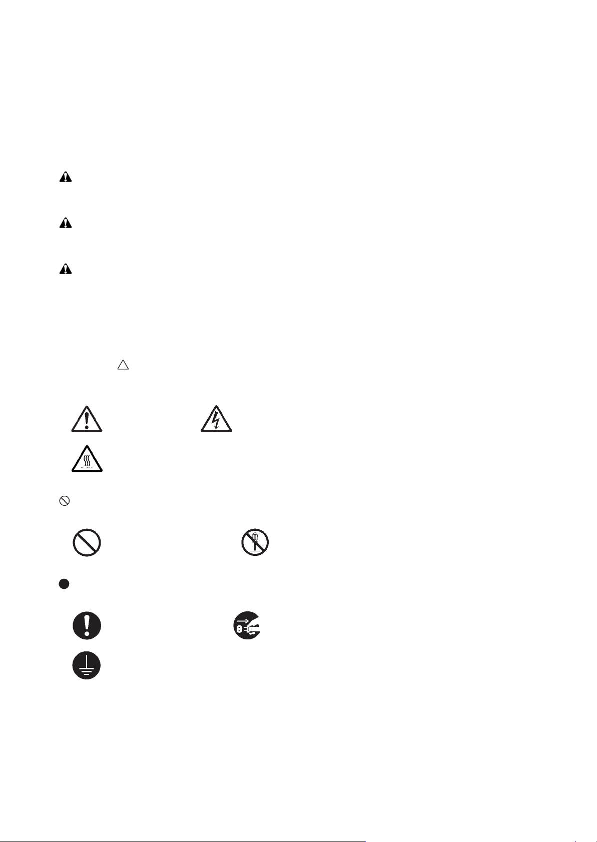
Symbols
The triangle ( ) symbol indicates a warning including danger and caution. The specific point of attention is
shown inside the symbol.
General warning. Warning of risk of electric shock.
Warning of high temperature.
indicates a prohibited action. The specific prohibition is shown inside the symbol.
General prohibited action. Disassembly prohibited.
indicates that action is required. The specific action required is shown inside the symbol.
General action required. Remove the power plug from the wall outlet.
Always ground the copier.
Page 7

1. Installation Precautions
WARNING
• Do not use a power supply with a voltage other than that specified. Avoid multiple connections to
one outlet: they may cause fire or electric shock. When using an extension cable, always check that
it is adequate for the rated current. .....................................................................................................
• Connect the ground wire to a suitable grounding point. Not grounding the copier may cause fire or
electric shock. Connecting the earth wire to an object not approved for the purpose may cause
explosion or electric shock. Never connect the ground cable to any of the following: gas pipes, lightning rods, ground cables for telephone lines and water pipes or faucets not approved by the proper
authorities. ..........................................................................................................................................
CAUTION:
• Do not place the copier on an infirm or angled surface: the copier may tip over, causing injury. .........
• Do not install the copier in a humid or dusty place. This may cause fire or electric shock. .................
• Do not install the copier near a radiator, heater, other heat source or near flammable material. This
may cause fire. ...................................................................................................................................
• Allow sufficient space around the copier to allow the ventilation grills to keep the machine as cool
as possible. Insufficient ventilation may cause heat buildup and poor copying performance. ............
• Always handle the machine by the correct locations when moving it. .................................................
• Always use anti-toppling and locking devices on copiers so equipped. Failure to do this may cause
the copier to move unexpectedly or topple, leading to injury. ..............................................................
• Avoid inhaling toner or developer excessively. Protect the eyes. If toner or developer is accidentally
ingested, drink a lot of water to dilute it in the stomach and obtain medical attention immediately.
If it gets into the eyes, rinse immediately with copious amounts of water and obtain medical atten-
tion. .....................................................................................................................................................
• Advice customers that they must always follow the safety warnings and precautions in the copier’s
instruction handbook. .........................................................................................................................
Page 8
2. Precautions for Maintenance
WARNING
• Always remove the power plug from the wall outlet before starting machine disassembly. ................
• Always follow the procedures for maintenance described in the service manual and other related
brochures. ..........................................................................................................................................
• Under no circumstances attempt to bypass or disable safety features including safety mechanisms
and protective circuits. ........................................................................................................................
• Always use parts having the correct specifications. ............................................................................
• Always use the thermostat or thermal fuse specified in the service manual or other related brochure
when replacing them. Using a piece of wire, for example, could lead to fire or other serious acci-
dent. ...................................................................................................................................................
• When the service manual or other serious brochure specifies a distance or gap for installation of a
part, always use the correct scale and measure carefully. ..................................................................
• Always check that the copier is correctly connected to an outlet with a ground connection. ...............
• Check that the power cable covering is free of damage. Check that the power plug is dust-free. If it
is dirty, clean it to remove the risk of fire or electric shock. .................................................................
• Never attempt to disassemble the optical unit in machines using lasers. Leaking laser light may
damage eyesight. ...............................................................................................................................
• Handle the charger sections with care. They are charged to high potentials and may cause electric
shock if handled improperly. ...............................................................................................................
CAUTION
• Wear safe clothing. If wearing loose clothing or accessories such as ties, make sure they are safely
secured so they will not be caught in rotating sections. ......................................................................
• Use utmost caution when working on a powered machine. Keep away from chains and belts. ..........
• Handle the fixing section with care to avoid burns as it can be extremely hot. ..................................
• Check that the fixing unit thermistor, heat and press rollers are clean. Dirt on them can cause
abnormally high temperatures. ...........................................................................................................
Page 9

• Do not remove the ozone filter, if any, from the copier except for routine replacement. ......................
• Do not pull on the AC power cord or connector wires on high-voltage components when removing
them; always hold the plug itself. ........................................................................................................
• Do not route the power cable where it may be stood on or trapped. If necessary, protect it with a
cable cover or other appropriate item. ................................................................................................
• Treat the ends of the wire carefully when installing a new charger wire to avoid electric leaks. ..........
• Remove toner completely from electronic components. .....................................................................
• Run wire harnesses carefully so that wires will not be trapped or damaged. ......................................
• After maintenance, always check that all the parts, screws, connectors and wires that were
removed, have been refitted correctly. Special attention should be paid to any forgotten connector,
trapped wire and missing screws. .......................................................................................................
• Check that all the caution labels that should be present on the machine according to the instruction
handbook are clean and not peeling. Replace with new ones if necessary. .......................................
• Handle greases and solvents with care by following the instructions below: ......................................
· Use only a small amount of solvent at a time, being careful not to spill. Wipe spills off completely.
· Ventilate the room well while using grease or solvents.
· Allow applied solvents to evaporate completely before refitting the covers or turning the power
switch on.
· Always wash hands afterwards.
• Never dispose of toner or toner bottles in fire. Toner may cause sparks when exposed directly to
fire in a furnace, etc. ...........................................................................................................................
• Should smoke be seen coming from the copier, remove the power plug from the wall outlet immedi-
ately. ...................................................................................................................................................
3. Miscellaneous
WARNING
• Never attempt to heat the drum or expose it to any organic solvents such as alcohol, other than the
specified refiner; it may generate toxic gas. ........................................................................................
• Keep the machine away from flammable liquids, gases, and aerosols. A fire or an electric shock
might occur. ........................................................................................................................................
Page 10

This page is intentionally left blank.
Page 11

1 Specifications
1-1 Specifications ........................................................................................................................... 1-1
(1) Common function ................................................................................................................ 1-1
(2) Copy Functions.................................................................................................................... 1-3
(3) Printer Functions ................................................................................................................. 1-3
(4) Scanner Functions............................................................................................................... 1-4
(5) FAX Functions ..................................................................................................................... 1-4
(6) Document Processor ...........................................................................................................1-5
(7) Paper Feeder (PF-1100)(Option) ........................................................................................ 1-6
1-2 Part Names............................................................................................................................... 1-7
(1) Machine Exterior.................................................................................................................. 1-7
(2) Connectors/Interior .............................................................................................................. 1-8
(3) With Optional Equipments Attached .................................................................................... 1-9
(4) Operation Panel (TSI)........................................................................................................1-10
(5) Operation Panel Keys (LCD) ............................................................................................. 1-11
1-3 Overview of Optional Equipment ............................................................................................ 1-13
(1) Expansion Memory............................................................................................................ 1-14
(2) PF-1100 "Paper Feeder" ................................................................................................... 1-15
(3) Card Authentication Kit(B) "Card Authentication Kit"......................................................... 1-15
(4) UG-33 "ThinPrint Option" .................................................................................................. 1-15
(5) SD/SDHC Memory Card.................................................................................................... 1-15
2S0/2S1/2S2/2S3/2S4/2S5/2SG/2SH/3RA-1
CONTENTS
2 Installation
2-1 Environment ............................................................................................................................. 2-1
2-2 Installing the main unit .............................................................................................................. 2-2
(1) Unpacking and checking bundled items .............................................................................. 2-3
(1-1) Main unit..................................................................................................................... 2-3
(1-2) Paper Feeder (Option) ............................................................................................... 2-4
(2) Installing the optional equipment ......................................................................................... 2-5
(3) Connecting to other device.................................................................................................. 2-5
(4) Connecting to the cable....................................................................................................... 2-6
(4-1) LAN Cable .................................................................................................................. 2-6
(4-2) USB cable .................................................................................................................. 2-6
(5) Loading Paper ..................................................................................................................... 2-7
(6) Power-up ............................................................................................................................. 2-9
(7) Default (TSI model) ........................................................................................................... 2-10
(7-1) Setting Date and Time.............................................................................................. 2-10
(7-2) Network Settings ...................................................................................................... 2-11
(7-3) Altitude Adjustment Setting ...................................................................................... 2-12
(7) Default (LCD model)..........................................................................................................2-13
(7-1) Setting Date and Time.............................................................................................. 2-13
(7-2) Network Settings ...................................................................................................... 2-14
(7-3) Altitude Adjustment Setting ...................................................................................... 2-16
(8) Installing Software ............................................................................................................. 2-17
(9) Output Maintenance Report (Executing Maintenance mode U000) (For Service) ............ 2-18
(10) Clearing the counts (Executing Maintenance Mode U927) (For service) .......................... 2-18
(11) Terminating the maintenance mode (For service)............................................................. 2-18
(12) Installing the main unit is complete.................................................................................... 2-18
Page 12

3 Machine Design
3-1 Cross-section view ................................................................................................................... 3-1
(1) Main unit + Document processor + Paper feeder (option)................................................... 3-1
3-2 The configuration of the electrical components ........................................................................ 3-2
(1) Electric parts........................................................................................................................ 3-2
(1-1) Machine left side ........................................................................................................ 3-2
(1-2) Machine right side ...................................................................................................... 3-3
(1-3) Document processor .................................................................................................. 3-4
(1-4) Paper feeder (option) ................................................................................................. 3-4
(2) Descriptions about the major PWBs.................................................................................... 3-5
(2-1) Main/Engine PWB ...................................................................................................... 3-5
(2-2) High-voltage PWB ...................................................................................................... 3-5
(2-3) Power source PWB .................................................................................................... 3-5
(2-4) Operation panel PWB (TSI)........................................................................................ 3-6
(2-5) Operation panel PWB (LCD) ...................................................................................... 3-6
(3) Electric parts layout ............................................................................................................. 3-7
(3-1) PWBs ......................................................................................................................... 3-7
(3-2) Sensors and Switches.............................................................................................. 3-10
(3-3) Motors ...................................................................................................................... 3-13
(3-4) Others....................................................................................................................... 3-15
3-3 Drive system ........................................................................................................................... 3-17
(1) Drive system for the paper conveying ............................................................................... 3-17
(2) Each section drive ............................................................................................................. 3-18
(2-1) Primary paper feed drive .......................................................................................... 3-18
(2-2) Drum drive................................................................................................................3-18
(2-3) Developer drive ........................................................................................................ 3-19
(2-4) Fuser unit drive......................................................................................................... 3-19
3-4 Mechanical construction ......................................................................................................... 3-20
(1) Paper feed section............................................................................................................. 3-20
(1-1) Cassette paper feed section..................................................................................... 3-20
(1-2) MP tray paper feed section ...................................................................................... 3-22
(2) Optical section ................................................................................................................... 3-24
(2-1) Image scanner unit................................................................................................... 3-24
(2-2) Laser scanner unit.................................................................................................... 3-26
(3) Developer section.............................................................................................................. 3-28
(3-1) Developer unit .......................................................................................................... 3-28
(4) Drum section ..................................................................................................................... 3-30
(4-1) Main charger unit...................................................................................................... 3-30
(4-2) Cleaning ................................................................................................................... 3-30
(5) Conveying/Transfer and Separation section ..................................................................... 3-32
(6) Fuser section ..................................................................................................................... 3-34
(7) Eject and feedshift section................................................................................................. 3-36
(8) Duplex conveying section.................................................................................................. 3-38
(9) Document processor ......................................................................................................... 3-40
(10) Paper feeder (option)......................................................................................................... 3-42
2S0/2S1/2S2/2S3/2S4/2S5/2SG/2SH/3RA-1
4 Maintenance
4-1 Precautions for the maintenance ..............................................................................................4-1
(1) Precautions.......................................................................................................................... 4-1
(2) Storage and handling of the drum ....................................................................................... 4-1
(3) Storage of the toner container ............................................................................................. 4-1
Page 13

2S0/2S1/2S2/2S3/2S4/2S5/2SG/2SH/3RA-1
(4) Screening of the toner container ......................................................................................... 4-2
4-2 Maintenance parts .................................................................................................................... 4-3
(1) Maintenance kits.................................................................................................................. 4-3
(2) Executing the maintenance mode after replacing the maintenance kit ............................ 4-3
(3) Maintenance parts list.......................................................................................................... 4-3
(4) Periodic maintenance Procedures....................................................................................... 4-4
4-3 Maintenance parts replacement procedures ............................................................................ 4-5
(1) Cassette paper feed section................................................................................................ 4-5
(1-1) Detaching and reattaching the Paper feed roller........................................................ 4-5
(1-2) Detaching and reattaching the retard roller ................................................................ 4-6
(1-3) Detaching and reattaching the MP paper feed pulley ................................................ 4-8
(2) Developer section.............................................................................................................. 4-10
(2-1) Detaching and reattaching the developer unit.......................................................... 4-10
(3) Drum section ..................................................................................................................... 4-11
(3-1) Detaching and reattaching the drum unit ................................................................. 4-11
(3-2) Detaching and reattaching the main charger unit..................................................... 4-13
(4) Transfer section................................................................................................................. 4-14
(4-1) Detaching and reattaching the transfer roller unit .................................................... 4-14
(5) Fuser section ..................................................................................................................... 4-17
(5-1) Detaching and reattaching the fuser unit.................................................................. 4-17
4-4 Disassembly and Reassembly ............................................................................................... 4-21
(1) Outer covers ...................................................................................................................... 4-21
(1-1) Detaching and reattaching the left rear cover .......................................................... 4-21
(1-2) Detaching and reattaching the ISU rear cover ......................................................... 4-21
(1-3) Detaching and reattaching the ISU left cover ........................................................... 4-22
(1-4) Detaching and reattaching the ISU right cover......................................................... 4-22
(1-5) Detaching and reattaching the left cover.................................................................. 4-23
(1-6) Detaching and reattaching the right cover................................................................ 4-24
(1-7) Detaching and reattaching the front cover ............................................................... 4-26
(1-8) Detaching and reattaching the rear cover ................................................................ 4-27
(2) Optical section ................................................................................................................... 4-28
(2-1) Detaching and reattaching the laser scanner unit (LSU).......................................... 4-28
(2-2) Detaching and reattaching the image scanner unit (ISU)......................................... 4-39
(2-3) Detaching and reattaching the operation panel (TSI model).................................... 4-45
(2-4) Detaching and reattaching the operation panel (LCD model) .................................. 4-47
(2-5) Detaching and reattaching the ISU top frame .......................................................... 4-48
(2-6) Detaching and reattaching the scanner carriage assembly ..................................... 4-48
(3) Drive section...................................................................................................................... 4-49
(3-1) Detaching and reattaching the main motor .............................................................. 4-49
(3-2) Detaching and reattaching the fuser pressure release drive unit ............................. 4-54
(3-3) Detaching and reattaching the MP solenoid (front side) .......................................... 4-60
(3-4) Detaching reattaching the clutch. ............................................................................. 4-64
(3-5) Detaching and reattaching the eject solenoid .......................................................... 4-70
(4) Others................................................................................................................................ 4-83
(4-1) Detaching and reattaching the speaker.................................................................... 4-83
(4-2) Detaching and reattaching the eraser ...................................................................... 4-89
(4-3) Replacing the language sheet (TSI model) .............................................................. 4-91
(4-4) Replacing the language sheet (LCD model) ............................................................ 4-92
(4-5) Fan motor attachment direction................................................................................ 4-93
(5) PWBs................................................................................................................................. 4-94
(5-1) Detaching and reattaching the main/engine PWB.................................................... 4-94
Page 14

2S0/2S1/2S2/2S3/2S4/2S5/2SG/2SH/3RA-1
(5-2) Detaching and reattaching the high voltage PWB .................................................. 4-102
(5-3) Detaching and reattaching the low voltage power source PWB............................. 4-110
(5-4) Detaching and reattaching the FAX PWB .............................................................. 4-116
(5-5) Detaching and reattaching the Wi-Fi PWB. ............................................................ 4-124
(5-6) Detaching and reattaching the USB PWB. ............................................................. 4-126
(5-7) Detaching and reattaching the operation panel PWB (TSI model)......................... 4-138
(5-8) Detaching and reattaching the operation panel PWB (LCD model) ....................... 4-141
(6) Detaching and reattaching the document processor ....................................................... 4-143
(6-1) Detaching and reattaching the DP pick up pulley,
DP paper feed roller and DP separation pad ......................................................... 4-143
(6-2) Detaching and reattaching the DP front cover ....................................................... 4-145
(6-3) Detaching and reattaching the DP rear cover ........................................................ 4-146
(6-4) Detaching and reattaching the DP main motor ...................................................... 4-146
4-5 Maintenance parts replacement procedures (option) ........................................................... 4-148
(1) Paper feeder.................................................................................................................... 4-148
(1-1) Detaching and reattaching the PF main PWB ........................................................ 4-148
(1-2) Detaching and reattaching PF conveying motor. ................................................... 4-149
(1-3) Detaching and reattaching the PF clutch. .............................................................. 4-152
5Firmware
5-1 Firmware update (TSI model) ................................................................................................... 5-1
5-2 Firmware update (LCD model) ................................................................................................. 5-6
6 Maintenance mode
6-1 Maintenance mode ................................................................................................................... 6-1
(1) Executing the maintenance mode ....................................................................................... 6-1
(2) Maintenance modes list ......................................................................................................6-2
(2-1) Content of the maintenance mode ............................................................................. 6-5
6-2 Service modes ...................................................................................................................... 6-107
(1) TSI model ........................................................................................................................ 6-107
(1-1) Executing the service mode ................................................................................... 6-107
(1-2) Descriptions of service modes ............................................................................... 6-109
(2) LCD model....................................................................................................................... 6-113
(2-1) Executing the service mode ................................................................................... 6-113
(2-2) Descriptions of service modes ............................................................................... 6-115
7Troubleshooting
7-1 Conveying failures .................................................................................................................... 7-1
(1) Prior standard check items .................................................................................................. 7-1
(1-1) Paper jam due to the cover-open detection ............................................................... 7-2
(1-2) Paper jam due to the wave or curl in the fuser section of the damp paper ................ 7-2
(1-3) Paper jam due to the dog-ear, paper skew,
paper creases, fusing failure or the paper curl ........................................................... 7-2
(1-4) Paper jam caused by the conveying guide, paper entry guide or the feedshift guide 7-3
(1-5) Paper jam caused by incorrectly loaded paper in the cassette .................................. 7-3
(1-6) Paper jam due to the inferior paper............................................................................ 7-3
(1-7) Paper jam caused by the conveying rollers or the paper feed pulleys ....................... 7-4
(1-8) Paper jam due to the sensor ...................................................................................... 7-5
(1-9) Paper jam due to the setting / detection failure .......................................................... 7-5
(1-10) Paper jam due to the static electricity......................................................................... 7-6
Page 15

2S0/2S1/2S2/2S3/2S4/2S5/2SG/2SH/3RA-1
(1-11) Paper jam caused by installation in the environment
where paper inside the cassette is always moist. ...................................................... 7-6
(2) Paper jam indication ............................................................................................................ 7-7
(3) Paper jam detection condition ............................................................................................. 7-8
(4) First check item ................................................................................................................. 7-12
7-2 Self diagnostic ........................................................................................................................ 7-15
(1) Self diagnostic function...................................................................................................... 7-15
(2) Self diagnostic codes......................................................................................................... 7-15
(3) System Error (Fxxxx) Outline ............................................................................................ 7-32
7-3 Image formation failure ........................................................................................................... 7-37
(1) Poor image (due to DP and scanner reading) ................................................................... 7-38
(1-1) No image appears (entirely white)............................................................................ 7-39
(1-2) No image appears (entirely black)............................................................................ 7-41
(1-3) The entire image is faint ........................................................................................... 7-42
(1-4) The background is colored ....................................................................................... 7-44
(1-5) Vertical white streaks or bands appear .................................................................... 7-46
(1-6) Vertical white streaks or bands appear .................................................................... 7-47
(1-7) Horizontal black streaks appear ............................................................................... 7-49
(1-8) The image is partly dark or bright............................................................................. 7-51
(1-9) Black dots appear in the image ................................................................................ 7-53
(1-10) Characters are blurred ............................................................................................. 7-54
(1-11) Regular error images arise at the leading edge of the original and copy. ................ 7-56
(1-12) The image is partly missing...................................................................................... 7-57
(1-13) The image is blurred................................................................................................. 7-59
(1-14) Image center does not align with the original center ................................................ 7-61
(1-15) Moire ........................................................................................................................ 7-62
(1-16) Skewed image.......................................................................................................... 7-63
(1-17) Abnormal image ....................................................................................................... 7-64
(2) Poor image (Image forming factor).................................................................................... 7-65
(2-1) No image appears (entirely white)............................................................................ 7-66
(2-2) No image appears (entirely black)............................................................................ 7-67
(2-3) The entire image is faint ........................................................................................... 7-68
(2-4) It is foggy at the background image ......................................................................... 7-70
(2-5) Vertical white streaks or bands appear .................................................................... 7-71
(2-6) Vertical white streaks or bands appear .................................................................... 7-72
(2-7) There are horizontal bands in white or black............................................................ 7-73
(2-8) Uneven density vertically.......................................................................................... 7-74
(2-9) Uneven density horizontally ..................................................................................... 7-75
(2-10) Black dots appear in the image ................................................................................ 7-76
(2-11) Offset occurs ............................................................................................................7-76
(2-12) The image is partly missing...................................................................................... 7-77
(2-13) The image is blurred................................................................................................. 7-77
(2-14) Irregular horizontal white streaks appear in the image
Dots appear in the image ......................................................................................... 7-78
(2-15) Granular image (low solid image density) ................................................................ 7-79
7-4 Electric failure ......................................................................................................................... 7-80
7-5 Mechanical failure................................................................................................................... 7-83
7-6 Error codes ............................................................................................................................. 7-84
(1) Scan to SMB error code .................................................................................................... 7-84
(2) Scan to FTP error code ..................................................................................................... 7-85
(3) Scan to E-mail error code.................................................................................................. 7-86
Page 16

7-7 Error codes ............................................................................................................................. 7-88
(1) Error codes ........................................................................................................................ 7-88
(2) Error codes ........................................................................................................................ 7-89
(2-1) Error code table: U004XX Interrupted phase B ........................................................ 7-92
(2-2) Error code table: U006XX Problems with the unit .................................................... 7-93
(2-3) Error code table: U008XX Page transmission error ................................................. 7-93
(2-4) Error code table: U009XX Page reception error....................................................... 7-93
(2-5) Error code table: U010XX G3 transmission error ..................................................... 7-94
(2-6) U011XX G3 reception error...................................................................................... 7-96
(2-7) Error code table: U017XX V.34 transmission error .................................................. 7-97
(2-8) Error code table: U018XX V.34 reception error........................................................ 7-98
(2-9) Error code table: U023XX Page reception error....................................................... 7-98
(2-10) Error code table: U044XX Encrypted transmission error ......................................... 7-98
8PWBs
8-1 Description for PWB ................................................................................................................. 8-1
(1) Main/Engine PWB ............................................................................................................... 8-1
(2) High voltage PWB .............................................................................................................8-10
(3) Low voltage power supply PWB ........................................................................................ 8-12
(4) Operation panel PWB (TSI)............................................................................................... 8-14
(5) Operation panel PWB (LCD) ............................................................................................. 8-19
(6) PF main PWB (option)....................................................................................................... 8-21
2S0/2S1/2S2/2S3/2S4/2S5/2SG/2SH/3RA-1
9 Appendixes
9-1 Appendixes ............................................................................................................................... 9-1
(1) Repetitive defects gauge .....................................................................................................9-1
(2) Firmware environment commands ...................................................................................... 9-2
(3) Chart of image adjustment procedures ............................................................................. 9-10
(4) Wiring diagram .................................................................................................................. 9-13
(4-1) Standard................................................................................................................... 9-13
(4-2) PF-1100 (Options).................................................................................................... 9-17
Installation Guide
PF-1100 (250 sheets × 1 Paper Feeder)
Page 17

1 Specifications
1-1 Specifications
(1) Common function
Item Description
2S0/2S1/2S2/2S3/2S4/2S5/2SG/2SH/3RA
40 ppm model
35 ppm model
Type Desktop
Printing Method Electrophotography by semiconductor laser
Paper Weight Cassette
Multi Purpose
Tra y
Paper Type Cassette Plain, Rough, Recycled, Preprinted, Bond, Color, Prepunched,
Multi Purpose
Tra y
Paper Size Cassette A4, A5-R, A5, A6, B5, Letter, Legal, Folio, 216 × 340 mm,
Multi Purpose
Tra y
M2640idw M2540dw M2540dn M2040dn
M2735dw M2635dw M2635dn M2135dn
2
60 to 163 g/m
60 to 220 g/m², 209g/m² (Hagaki)
Letterhead, Thick, High Quality, Custom 1 to 8 (Duplex:
Same as Simplex)
Plain, Transparency (OHP film), Rough, Vellum, Labels, Recycled, Preprinted, Cardstock, Coated, Color, Prepunched, Letterhead, Envelope,
Thick, High Quality, Custom 1 to 8
Statement, Executive, Oficio II, 16K, B5(ISO),
Custom (105 x 148 to 216 x 356 mm)
A4, A5-R, A5, A6, B5, B6, Letter, Legal, Folio, 216 × 340 mm,
Statement-R,Executive, Oficio II, 16K, B5(ISO),
Envelope #10, Envelope #9, Envelope #6 3/4,
Envelope Monarch, Envelope DL, Envelope C5, Hagaki (Cardstock), Oufukuhagaki (Return postcard), youkei 4, youkei 2,
Custom (70 x 148 to 216 x 356 mm)
Printable Area Print margin for top, bottom and both sides is 4.2 mm.
Warm-up Time
(23°C/ 73.4°F,
60%)
Paper Capacity
Output Tray
Capacity
Image Write System Semiconductor laser and electrophotography (twin beams)
Scanning light source 3-color LED light source
Scanning method Flat-face scanning method with the CIS contact image sensor
Photoconductor OPC drum (diameter 30 mm)
Charging system Positive charge scorotron system
Power on 20 seconds or
less
Sleep 10 seconds or less
Cassette
Multi Purpose
Tra y
Inner tray 150 sheets (80 g/m²)
300 Sheets (64 g/m2)
250 Sheets (80 g/m2)
120 sheets (A4/Letter or smaller) (64 g/m2)
100 sheets (A4/Letter or smaller) (80 g/m2)
17 seconds or less
*1
*1
1-1
Page 18
2S0/2S1/2S2/2S3/2S4/2S5/2SG/2SH/3RA
Item Description
40 ppm model
35 ppm model
M2640idw M2540dw M2540dn M2040dn
M2735dw M2635dw M2635dn M2135dn
Developer system Magnetic mono-component developing system
Toner: magnetic toner
Toner feed system: leveled toner feed
Transfer system Transfer roller method
Separation system Curvature separation + discharger needle (grounded) : except
100 V model
Curvature separation + discharger needle (DC voltage
impressed) : 100 V model only
Cleaning system Counter blade
Charge erasing system Exposure by cleaning lamp (LED)
Fusing system Sliding belt + foam press roller system
Heat source: halogen heater
Abnormal temperature preventing device: 2 thermocat
Operation Panel 4.3inch TSI 5-line LCD
Memory 512 MB
Interface USB Interface Connector: 1 (Hi-Speed USB)
Network interface: 1
(10 BASE-T/100 BASE-TX/1000 BASE-T)
USB Port: 1 (Hi-Speed USB)
Fax Fax: 1Fax: 1Fax: 1-
Operating
Environment
Wireless LAN Wireless LAN
support Only
Temperatur e 10 to 32.5°C/50 to 90.5°F
Humidity 10 to 80%
Wireless LAN
support Only
--
Altitude 3,500 m/11,482 ft maximum
Brightness 1,500 lux maximum
Dimension (W × D × H) 16.42" × 16.23" × 17.21"417 × 412 × 437 mm (Metric Model)
18.71" × 16.23" × 17.21"475 × 412 × 437 mm (Inch Model)
Weight (without toner container) Approx. 41.9 lb/Approx. 19 kg
Space Required (W × D) (Using multi purpose tray) 14.77" × 28.47"375 × 723 mm
(Metric Model)
(Using multi purpose tray) 14.77" × 28.47"375 × 723 mm (Inch
Model)
Power Source AC100V, 50/60Hz, 9.7A
AC120 V, 60 Hz, 8.7A
AC220 to 240V, 50 Hz, 4.4 A
*1 Up to upper limit height line in the cassette.
1-2
Page 19

(2) Copy Functions
2S0/2S1/2S2/2S3/2S4/2S5/2SG/2SH/3RA
Item Description
40 ppm model 35 ppm model
Copy Speed A4/A5 40 sheets/min
Letter 42 sheets/min
Legal 34 sheets/min
B5 27 sheets/min
A5-R 19 sheets/min
A6 19 sheets/min
16K 22 sheets/min
First Copy Time
(A4, place on the platen, feed
from Cassette)
Zoom Level Manual mode: 25 to 400%, 1% increments
Continuous Copying 1 to 999 sheets
Resolution 600 × 600 dpi
Supported Original Types Sheet, Book, 3-dimensional objects (maximum original size:
Original Feed System Fixed
6.4 seconds or less 6.9 seconds or less
Auto mode:Preset Zoom
Legal/Folio)
A4/A5 35 sheets/min
Letter 37 sheets/min
Legal 30 sheets/min
B5 24 sheets/min
A5-R 17 sheets/min
A6 17 sheets/min
16K 20 sheets/min
(3) Printer Functions
Printing Speed Same as Copying Speed.
First Print Time (A4, feed from
Cassette)
Resolution 300 dpi × 300 dpi, 600 dpi × 600 dpi, 1200 dpi equivalent ×
Operating System Windows XP, Windows Server 2003, Windows Vista, Windows
Interface USB Interface Connector: 1 (Hi-Speed USB)
Page Description Language PRESCRIBE
Emulations PCL6(PCL-XL, PCL5c) KPDL3, (PostScript3 compatible),
Item Description
40 ppm model 35 ppm model
6.4 seconds or less 6.8 seconds or less
1200 dpi equivalent, 1800 dpi equivalent × 600 dpi
7, Windows 8, Windows 8.1, Windows 10, Windows Server
2008/R2, Windows Server 2012/R2, Mac OS X v10.5 or later
Network interface: 1
(10 BASE-T/100 BASE-TX/1000 BASE-T)
Wireless LAN support Only
PDF, XPS, OpenXPS
1-3
Page 20

(4) Scanner Functions
Item Description
2S0/2S1/2S2/2S3/2S4/2S5/2SG/2SH/3RA-1
Resolution
300 × 300 dpi, 200 × 200 dpi, 200 × 100 dpi, 600 × 600 dpi
*1
,
400 × 400 dpi*1, 200 × 400 dpi*1
File Format TIFF (MMR/JPEG compression), JPEG, PDF (MMR/JPEG
compression), High compressive PDF, XPS, OPEN XPS,
Encrypted PDF, PDF/A-1
Scanning Speed
*2
(A4 landscape, 300 dpi × 300 dpi, Image quality: Text/Photo
original)
1-sided B/W: 40 images/min, Color: 23 images/min
2-sided B/W: 32 images/min, Color: 16 images/min
*3
Interface Ethernet (10 BASE-T/100 BASE-TX/1000 BASE-T), USB
Transmission System
SMBv3, SMTP, FTP, FTP over SSL, USB, TWAIN
*4
, WIA*5,
WSD
*1 One-sided scanning
*2 When using the document processor (except TWAIN and WIA scanning)
*3 Simultaneous duplex scan: 40ppm model only
*4 Available Operating System: Windows XP/Windows Vista/Windows Server 2003/Windows Server 2008/
Windows Server 2008 R2/Windows 7/Windows 8/Windows 8.1/Windows 10/Windows Server 2012/Windows Server 2012 R2
*5 Available Operating System: Windows Vista/Windows Server 2008/Windows Server 2008 R2/Windows 7/
Windows 8/
Windows 8.1/Windows Server 2012/Windows Server 2012 R2/Windows 10
(5) FAX Functions
FAX Function
Compatibility G3
Communication Line Subscriber telephone line
Transmission Time Less than 3 seconds (33600 bps, JBIG, ITU-T A4-R #1 chart)
Transmission Speed 33600/31200/28800/26400/24000/21600/19200/16800/14400/
Coding Scheme JBIG/MMR/MR/MH
Error Correction ECM
Original Size Max. width: 8 1/2"/216 mm, Max. length: 14 1/32"/356 mm
Automatic Document Feed Max. 50 sheets (with document processor)
Resolution Scan:
Item Description
12000/9600/7200/4800/2400 bps
200 × 100 dpi Normal (8 dot/mm × 3.85 line/mm)
200 × 200 dpi Fine (8 dot/mm × 7.7 line/mm)
200 × 400 dpi Super (Super Fine) (8 dot/mm × 15.4 line/mm)
400 × 400 dpi Ultra (Ultra Fine) (16 dot/mm × 15.4 line/mm)
Print: 600 dpi
Gradations 256 shades (Error diffusion)
One Touch Key
100 keys
*1
, 22 keys
*2
Multi-Station Transmission Max. 100 destinations
1-4
Page 21

Substitute Memory Reception 256 sheets or more (when using ITU-T A4 #1)
Image Memory Capacity 3.5 MB (standard)(For fax transmission and reception)
Report Output Send result report, FAX RX result report, Activity report, Status
*1 TSI model
*2 LCD model
Network FAX Function
Hardware IBM PC-AT compatible computer
Interface 10BASE-T, 100BASE-TX, 1000BASE-T, Wireless LAN sup-
2S0/2S1/2S2/2S3/2S4/2S5/2SG/2SH/3RA-1
Item Description
page
Item Description
*1
port
Operating system
Windows XP, Windows Server 2003, Windows Vista, Windows 7,
Windows 8, Windows 8.1, Windows 10, Windows Server
2008/R2,Windows Server 2012/R2
Transmission Resolution
200 × 100 dpi Normal (8 dot/mm × 3.85 line/mm)
200 × 200 dpi Fine (8 dot/mm × 7.7 line/mm)
400 × 400 dpi Ultra (Ultra Fine) (16 dot/mm × 15.4 line/mm)
Document Size Letter, Legal, Statement, A4, A5, Folio, B5(JIS)
FAX Del ayed Transmit Based on settings in the Network FAX Driver (setting is possi-
ble to any 1 minute increment within the subsequent 24 hour
period)
Transmit and Print Fax transmission and print out at the machine is available
Broadcast Transmission Max. 100 destinations
Job Accounting Requires the input of a Login User Name and Password in the
Network FAX Driver when User Login, is turn ON in the fax
machine.
Requires the input of an Account ID in the Network FAX Driver
when Job Accounting, is turned ON in the fax machine.
Cover Page A format can be selected using the Network FAX Driver or a
template can be created.
*1 Wi-Fi model only
(6) Document Processor
Item Description
Supported Original Types Sheet originals
Paper Size Maximum: Folio/Legal
Paper Weight 50 to 160 g/m2
Loading Capacity
*1 Up to upper limit height line in the document processor
Minimum: Statement/A6
50 sheets (50 to 80 g/m²) maximum
Thick (120 g/m²) : 25 sheets
1-5
*1
Page 22

(7) Paper Feeder (PF-1100)(Option)
Item Description
Paper Supply Method Friction roller feeder
2S0/2S1/2S2/2S3/2S4/2S5/2SG/2SH/3RA
(No. Sheets: 250, 80 g/m2, 1 cassette)
Paper Size
A4, A5-R, A5, B5, A6, Letter, Legal, Folio, 216 × 340 mm,
Statement, Executive, Oficio II, 16K, B5(ISO),
Custom (105 x 148 to 216 x 356 mm)
Supported Paper Paper weight: 60 to 163 g/m²
Media types: Plain, Recycled, Material
Dimensions (W) × (D) × (H) 14.77" × 15.48" × 3.94" 375 × 393 × 100 mm
Weight Approx. 6.4 lb/Approx. 2.9 kg
1-6
Page 23
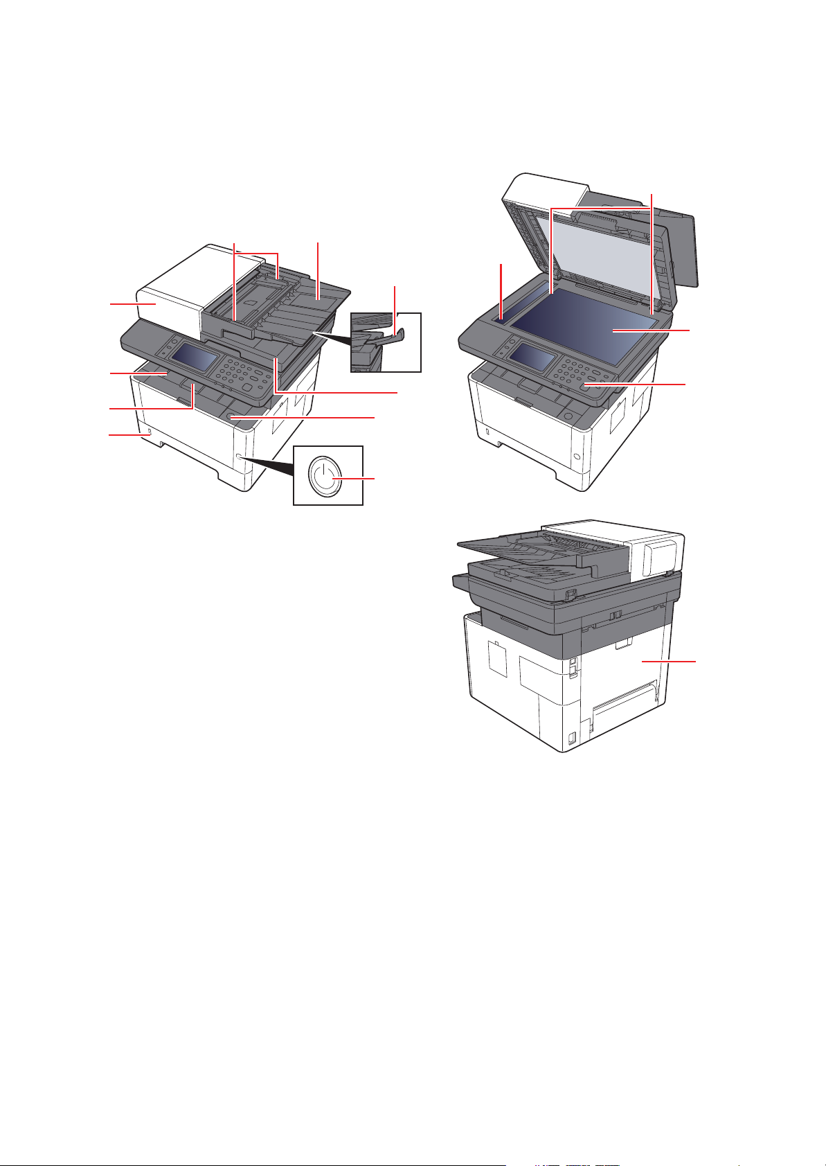
1-2 Part Names
(1) Machine Exterior
2S0/2S1/2S2/2S3/2S4/2S5/2SG/2SH/3RA
14
10
9
11
8
1
13
2
7
3
6
12
4
5
1 Document Processor
2 Inner Tray
3 Eject Stopper
4 Cassette 1
5 Power Switch
6 Front Cover Open Button
7 Original Eject Table
8 Original Stopper
15
9 Original Tray
10 Original Width Guides
11 Slit Glass
12 Operation Panel
13 Contact glass
14 Original Size Indicator Plates
15 Rear cover
1-7
Page 24
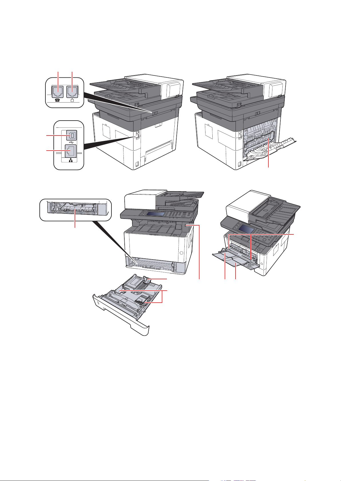
(2) Connectors/Interior
1 2
3
4
2S0/2S1/2S2/2S3/2S4/2S5/2SG/2SH/3RA
12
5
1. TEL Connector
2. LINE Connector
3. USB Interface Connector
4. Network Interface Connector
5. Feed Cover
6. Paper Length Guide
6
8
7
7. Paper Width Guides
8. USB Memory Slot
9. Multi Purpose Tray
10. Sub Tray
11. Paper Guides
12. Fuser Cover
11
9 10
1-8
Page 25
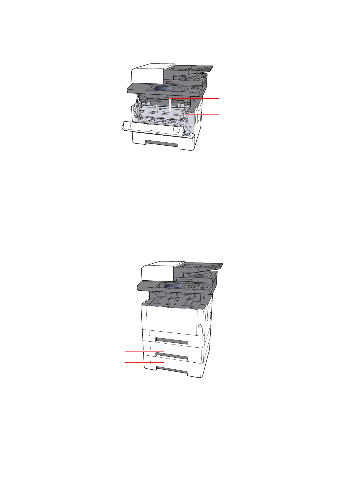
2S0/2S1/2S2/2S3/2S4/2S5/2SG/2SH/3RA
14
13
13. Toner Container Release Button
14. Toner Container
(3) With Optional Equipments Attached
1
1. Cassette 2
2. Cassette 3
2
1-9
Page 26
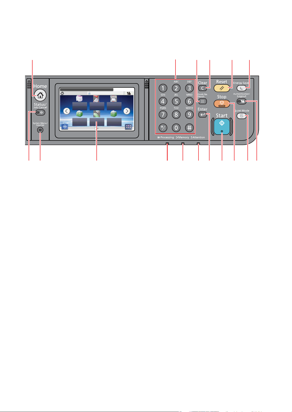
(4) Operation Panel (TSI)
Select the function.
nimdAemoH
Copy
Status
10:10
Send
Job Box
FAX
Removable
Memory
Task Screen
Sub
Address
Box
2S0/2S1/2S2/2S3/2S4/2S5/2SG/2SH/3RA
1 17
3 4 5 6 7 9
2 8 1210 11
16 15
14 13
1. [Home] key: Displays the Home screen.
2. [Status/Job Cancel] key: Displays the Status/Job Cancel screen.
3. [System Menu/Counter] key: Displays the System Menu/Counter screen.
4. Touch panel: Displays icons for configuring machine settings.
5. [Processing] indicator: Blinks while printing or sending/receiving.
6. [Memory] indicator: Blinks while the machine is accessing the machine memory or fax memory.
7. [Attention] indicator: Lights or blinks when an error occurs and a job is stopped.
8. [Enter] key: Finalizes numeric key entry, and finalizes details during setting of functions. Operates linked with the onscreen [OK].
9. [Start] key: Starts copying and scanning operations and processing for setting operations.
10. [Stop] key: Cancels or pauses the job in progress.
11. [Quiet Mode] key: Lower print and scan speed for quiet processing.
12. [Authentication/Logout] key: Authenticates user switching, and exits the operation for the current user (i.e. log out).
13. [Energy Saver] key: Puts the machine into Sleep Mode. Recovers from Sleep if in Sleep Mode.
14. [Reset] key: Returns settings to their default states.
15. [Clear] key: Clears entered numbers and characters.
16. [Quick No. Search] key: Specifies registered information such as address numbers and user IDs by number.
17. Numeric keys: Enter numbers and symbols.
1-10
Page 27
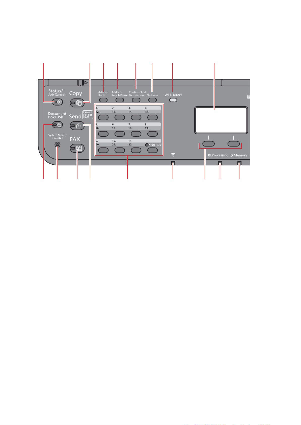
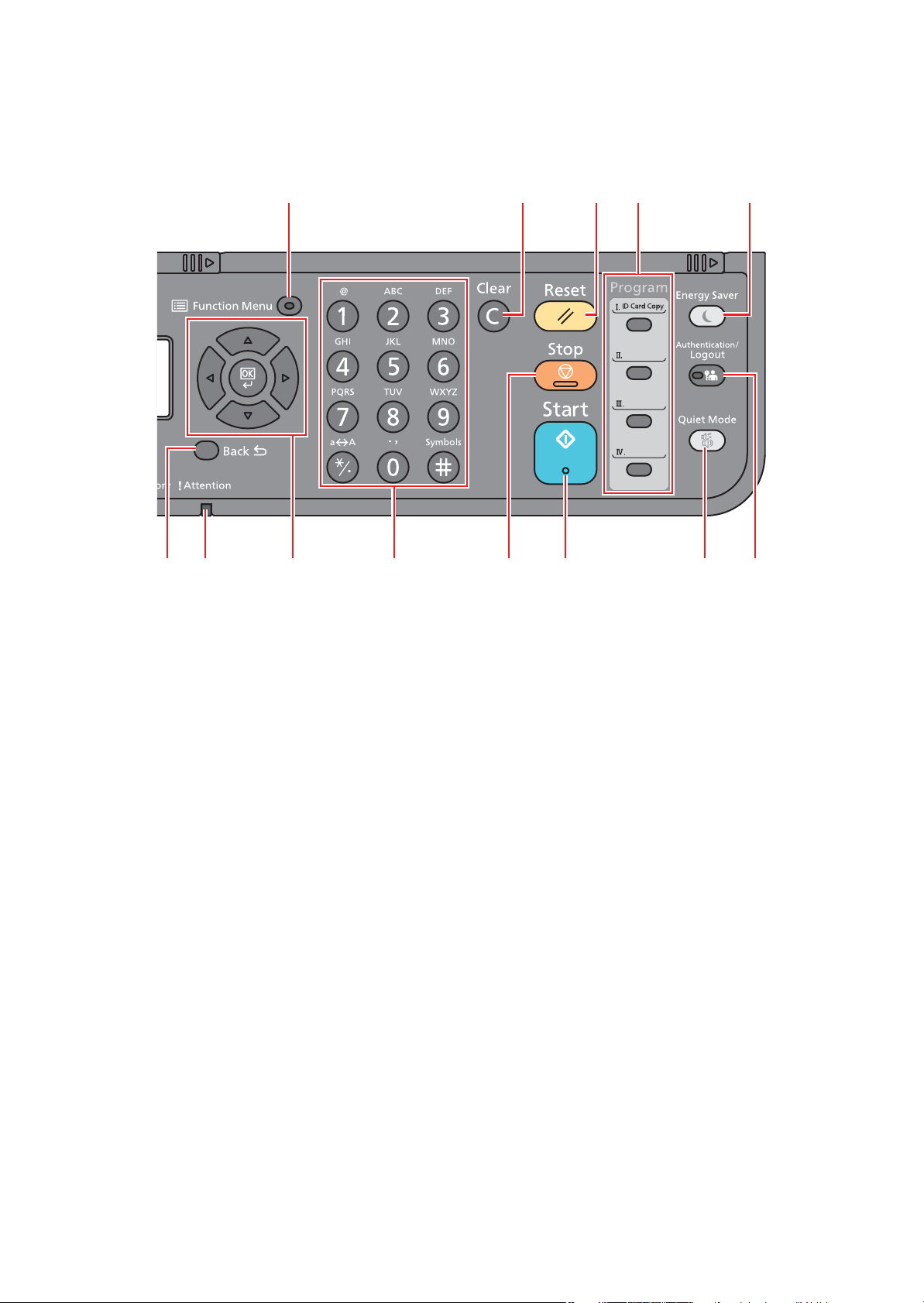
(5) Operation Panel Keys (LCD)
1
3 4 6 7 9 10
15 14 13 1216 11
8
17
2 5
2S0/2S1/2S2/2S3/2S4/2S5/2SG/2SH/3RA
1. [Status/Job Cancel] key: Displays the Status/Job Cancel screen.
2. [Document Box/USB] key: Displays the Document Box/USB screen.
3. [System Menu/Counter] key: Displays the System Menu/Counter screen.
4. [FAX] key: Displays the FAX screen.
5. [Send] key: Displays the screen for sending. You can change it to display the Address Book screen.
6. One Touch keys: Recalls the destination registered for One Touch Keys.
7. [Wi-Fi] indicator : Blinks during Wi-Fi connection.
8. Select keys: Selects the menu displayed at the bottom of the message display.
9. [Processing] indicator: Blinks while printing or sending/receiving.
10. [Memory] indicator: Blinks while the machine is accessing the machine memory or fax memory.
11. Message display: Displays the setting menu, machine status, and error messages.
12. [Wi-Fi Direct] key: Set Wi-Fi Direct, and show information necessary for connection and the connection status.
13. [On Hook] key: Switches between on-hook and off-hook when manually sending a FAX.
14. [Confirm/Add Destination] key: Confirms the destination or adds a destination.
15. [Address Recall/Pause] key: Calls the previous destination. Also used to enter a pause when entering a FAX number.
16. [Address Book] key: Displays the Address Book screen.
17. [Copy] key: Displays the Copy screen.
1-11
Page 28
2S0/2S1/2S2/2S3/2S4/2S5/2SG/2SH/3RA
18
20 21, 22 23 25 26 27
28
29
24
3031
19
18. [Function Menu] key: Displays the function menu screen.
19. [Back] key: Returns to the previous display.
20. [Attention] indicator: Lights or blinks when an error occurs and a job is stopped.
21. Arrow keys: Increments or decrements numbers, or selects menu in the message display. In addition, moves the
cursor when entering the characters.
22. [OK] key: Finalizes a function or menu, and numbers that have been entered.
23. Numeric keys: Enter numbers and symbols.
24. [Stop] key: Cancels or pauses the job in progress.
25. [Start] key: Starts copying and scanning operations and processing for setting operations.
26. [Quiet Mode] key: Lower print and scan speed for quiet processing.
27. [Authentication/Logout] key: Authenticates user switching, and exits the operation for the current user (i.e. log out).
28. [Energy Saver] key: Puts the machine into Sleep Mode. Recovers from Sleep if in Sleep Mode.
29. Program keys: Used to register or recall programs.
30. [Reset] key: Returns settings to their default states.
31. [Clear] key: Clears entered numbers and characters.
1-12
Page 29
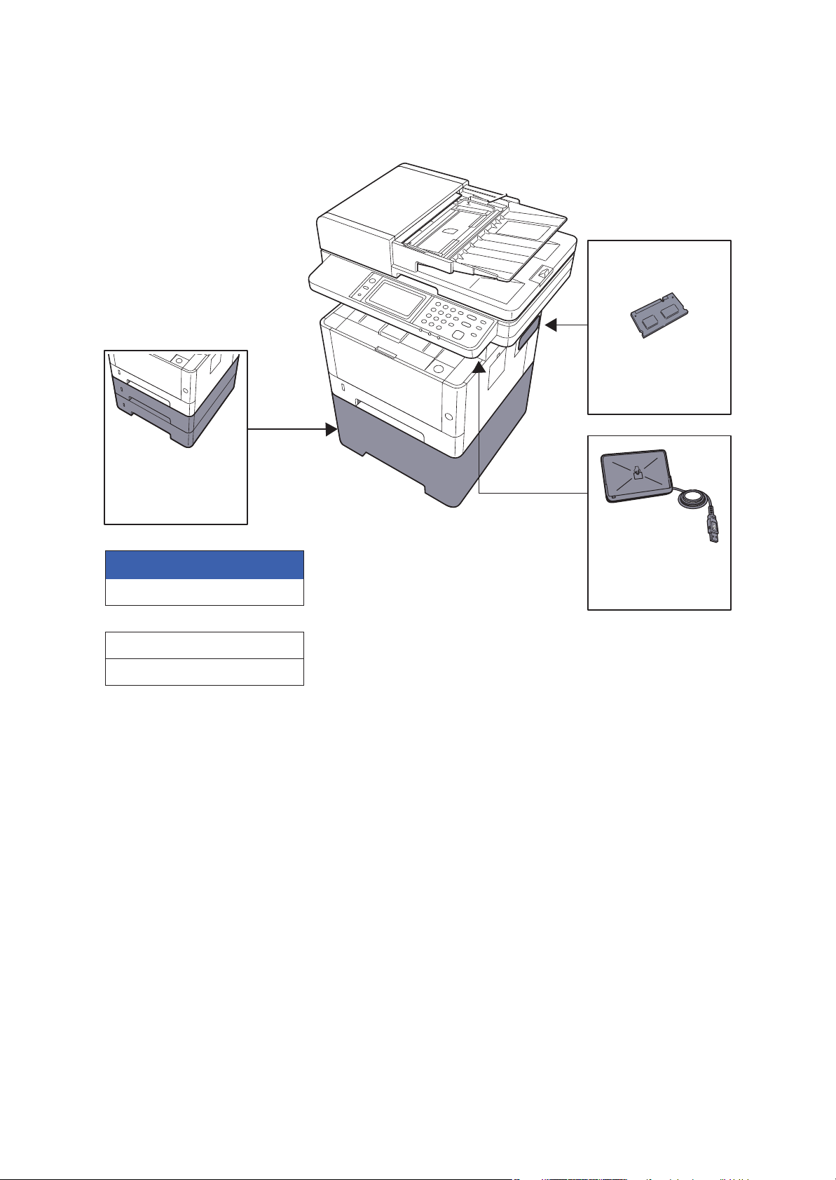
1-3 Overview of Optional Equipment
(1) Expansion Memory
Software option
(4) UG-33
(5) SD/SDHC Memory Card
(6) USB Keyboad
(3) Card Authentication
Kit (B)
The following optional equipment is available for the machine.
2S0/2S1/2S2/2S3/2S4/2S5/2SG/2SH/3RA
(2) PF-1100
1-13
Page 30
2S0/2S1/2S2/2S3/2S4/2S5/2SG/2SH/3RA
(1) Expansion Memory
The machine can perform the more multiple jobs simultaneously by adding more memories. You can increase the
machine's memory up to 1,536 MB by plugging in the optional memory modules.
Precautions for Handling the Memory Modules
To protect electronic parts, discharge static electricity from your body by wearing an antistatic wrist strap, if possible,
when you install the memory modules. If you do not have a wristband, touch a metal object to discharge static electricity
before inserting the memory.
Installing the Memory Modules
1. Turn off the machine and disconnect the power cord and interface cable.
2. Remove the cover.
3. Remove the memory module from its package.
4. With the memory connection terminal pointing toward the socket, align the cut-out part with the socket terminal and
insert directly in at an angle.
5. Carefully press the inserted memory down and into the machine.
6. Replace the covers.
1-14
Page 31

2S0/2S1/2S2/2S3/2S4/2S5/2SG/2SH/3RA
(2) PF-1100 "Paper Feeder"
Maximum two 250-sheet paper feeder can be installed.
(3) Card Authentication Kit(B) "Card Authentication Kit"
User login administration can be performed using ID cards. To do so, it is necessary to register ID card information on
the previously registered local user list.
(4) UG-33 "ThinPrint Option"
This application allows print data to be printed directly without a print driver.
(5) SD/SDHC Memory Card
SD/SDHC memory card is a micro chip card that can save optional fonts, macros, forms.
The machine is equipped with a slot for an SDHC memory card with a maximum size of 32 GB, and an SD memory card
with a maximum size of 2 GB.
Installing the Memory Modules
1. Turn off the machine and disconnect the power cord and interface cable.
2. Remove the cover.
3. Insert the SD/SDHC memory card into the SD/SDHC memory card slot.
4. Replace the covers.
1-15
Page 32

2S0/2S1/2S2/2S3/2S4/2S5/2SG/2SH/3RA
500mm or more
300mm or more 300mm or more
400mm or more
300mm or more
2 Installation 2-1 Environment
Installation environment
1. Temperature: 50 to 90.5°F (10 to 32.5°C) (But humidity should be 70% or less when the temperature is 90.5°F
(32.5°C).)
2. Humidity: 10 to 80%(But the temperature should be 86°F (30°C) or less when humidity is 80%.)
3. Power AC100V 50/60Hz 9.7A or more
AC120V 60Hz 8.7A or more
AC220 to 240V 50HzA 4.4A or more
4. Frequency fluctuation: 50Hz+/-2% or 60Hz+/-2%
Installation location
The operative environmental conditions are as follows:
Adverse environmental conditions may affect the image quality. It is recommended to use the machine as follows:
Humidity: 36 to 65% Temperature: 60.8 to 80.6°F or less (16 to 27°C).
Avoid the following locations when selecting a site for the machine.
Avoid locations near a window or with exposure to direct sunlight
Avoid locations with vibrations
Avoid locations with rapid temperature fluctuations
Avoid locations with direct exposure to hot or cold air
Avoid poorly ventilated locations
If the floor is delicate, when this machine is moved after installation, the floor material may be damaged by the casters.
During operation, some ozone is released, but the amount does not cause any ill effect to one's health.
If, however, the machine is used over a long period of time in a poorly ventilated room or when making an extremely
large number of copies, the smell may become unpleasant. To maintain the appropriate environment for copy work, it is
suggested that the room be properly ventilated.
Installation space
Figure 2-1
2-1
Page 33

2-2 Installing the main unit
Installation procedures
START
Unpacking and checking bundled items
Optional unit installation
Connecting the Other Dvices
2S0/2S1/2S2/2S3/2S4/2S5/2SG/2SH/3RA
Connecting the Interface Cable
Loading Paper
Turn the power on
Default Setting
Installing Software
Output a report
(Maintenance mode U000)
Maintenance report
User status report
Clearing the counts
(maintenance mode U927)
Exiting from the Maintenance mode
Output a Status report
Completion of installing the main unit
IMPORTANT
Default setting will take about 10 minutes for the toner installation.
Do not execute the maintenance mode during the initial setting drive.
2-2
Page 34

2S0/2S1/2S2/2S3/2S4/2S5/2SG/2SH/3RA
12
14
11
7
5
4
2
1
13
6
10
9
3
8
1. Right upper pad
2. Left upper pad
3. AC power cord
4. Product storage bag
5. Main unit
6. Front upper pad
7. Accessories box
8. Documents
9. Left bottom pad
10. Front bottom pad
11. Lower right pad
12. Lower left pad
13. inner frame
14. Outer box
(1) Unpacking and checking bundled items
(1-1) Main unit
Take out the main unit and accessories from the packing case.
Remove the tape and cushioning materials for packing from the main unit.
Figure 2-2
Note: Make sure to install the main unit on a level surface.
2-3
Page 35

(1-2) Paper Feeder (Option)
1
6
5
2
4
3
7
1. Left pad
2. Right pad
3. Main unit protective sheet
4. Paper Feeder
5. Main unit storage bag
6. Outer box
7. Cassette spacer
Take the paper feeder out of the packing case.
Remove the packing tape from the paper feeder.
2S0/2S1/2S2/2S3/2S4/2S5/2SG/2SH/3RA-1
Figure 2-3
2-4
Page 36

2S0/2S1/2S2/2S3/2S4/2S5/2SG/2SH/3RA
(2) Installing the optional equipment
Install the necessary optional equipment in the main unit by referring to the installation procedures.
(3) Connecting to other device
Prepare the cables necessary to suit the environment and purpose of the machine use.
When Connecting the Machine to the PC via USB
USB
When Connecting the Machine to the PC on the Network
Network
Network
NOTE
When using wireless LAN, it is not necessary to connect the network cable. It is necessary to change the initial setting of
the machine unit from System Menu to use the wireless LAN.
Cables that Can Be Used
Connection environment Function Necessary Cable
Connect a LAN cable to the
machine.
Connect a USB cable to the
machine.
IMPORTANT
When not using the USB2.0 compatible cable, it causes a failure.
Printer/Scanner/Network FAX LAN cable (10BASE-T, 100BASE-TX,
1000BASE-T)
Printer/Scanner (TWAIN/WIA) USB2.0 compatible cable (Hi-Speed USB compli-
ant, Max. 5.0m or less. with shield)
2-5
Page 37

(4) Connecting to the cable
(4-1) LAN Cable
1. Connect the LAN cable to the network interface connector.
2. Connect the other end of the cable to the hub or the PC.
3. Power on the machine and set the network.
2S0/2S1/2S2/2S3/2S4/2S5/2SG/2SH/3RA
(4-2)USB cable
1. Connect the USB cable to the USB interface connector.
2. Connect the other end of the cable to the PC.
3. Turn the power switch of the main unit on.
2-6
Page 38

(5) Loading Paper
1. Pull the cassette out of the main unit.
2S0/2S1/2S2/2S3/2S4/2S5/2SG/2SH/3RA
NOTE
When the bottom plate is lifted, push it until locked.
2. Adjust the paper length guide of the cassette.
2-7
Page 39

NOTE
In case of using Folio, Oficio ?or Legal
3. Adjust the paper width guides of the cassette
2S0/2S1/2S2/2S3/2S4/2S5/2SG/2SH/3RA
4. Load paper.
5. Insert the cassette slowly into the main unit as far as it goes.
6. Set the paper size and the paper type from the system menu.
IMPORTANT
Load it with the printing side facing down
Before loading paper in the cassette, fan the paper taken from a new package to separate it.
Before loading the paper, be sure that it is not curled or folded. Such paper may cause paper jams.
Load paper below the maximum paper level.
If the paper is loaded without adjusting the paper length guide and the paper width guides, it causes the skew paper
feeding and the paper jam.
2-8
Page 40

2S0/2S1/2S2/2S3/2S4/2S5/2SG/2SH/3RA-1
Precaution for Loading Paper
Separate the paper taken out of the package in the following procedures before loading it in the cassette.
Separate paper and align the edge of the paper in a flat place.
In addition, note the following.
In case of paper fold or curl, stretch it in a straight line. Such paper may cause a jam.
If paper is left in the high humidity environment after taking the paper out of the package, it causes a trouble with moisture. Keep paper remaining paper in the cassette into the sealed paper storage bag. Also, keep paper left on the MP tray
into the sealed paper storage bag.
If the machine is not used for a prolonged period, keep paper out of the cassette in the sealed storage bag in order to
protect it from humidity.
(6) Power-up
1. Turn the power switch on.
IMPORTANT
Initial Setup will take up to 10min to complete toner installation.
Do not execute maintenance mode during this period.
2-9
Page 41

2S0/2S1/2S2/2S3/2S4/2S5/2SG/2SH/3RA
(7) Default (TSI model)
Before using this machine, configure such settings as date and time, network configuration, and energy saving functions
as needed. The Machine Setup Wizard is launched when the equipment is turned on for the first time after being
installed. Also, configure the following settings if necessary.
NOTE
The default settings of the machine can be changed in System Menu.
Refer to the operation guide of the main unit about the items which can set from the system menu.
(7-1) Setting Date and Time
Follow the steps below to set the local date and time at the place of installation.
When you send an E-mail using the transmission function, the date and time as set here will be printed in the header of
the E-mail message. Set the date, time and time difference from GMT of the region where the machine is used.
NOTE
The correct time can be periodically set by obtaining the time from the network time server.
See page Command Center RX User Guide.
1. Displays the screen.
[System menu / counter] key > [Date/Timer/Energy Saver]
2. Configure the settings.
Select [Time Zone] > [Date/Time] > [Date Format] in this order for settings.
Item Descriptions
Time Zone Set the time difference from GMT. Choose the nearest listed location from
the list. If you select a region that utilizes summer time, configure settings
for summer time.
Date/Time Set the date and time for the location where you use the machine. If you
perform Send as E-mail, the date and time set here will be displayed on the
header.
Value: Year (2000 to 2037), Month (1 to 12), Day (1 to 31), Hour (00 to 23),
Minute (00 to 59), Second (00 to 59)
Date Format Select the display format of year, month, and date. The year is displayed in
Western notation.
Value: Month/Day/Year, Day/Month/Year, Year/Month/Day
2-10
Page 42

2S0/2S1/2S2/2S3/2S4/2S5/2SG/2SH/3RA
(7-2)Network Settings
Wired network setting
The machine is equipped with network interface, which is compatible with network protocols such as TCP/IP (IPv4),
TCP/IP (IPv6), NetBEUI, and IPSec. It enables network printing on the Windows, Macintosh, UNIX and other platforms.
Set up TCP/IP (IPv4) to connect to the Windows network.
Be sure to connect the network cable before configuring the settings.
If the user administration is effective, this can be changed by logging in with administrator privileges.
If the user login administration is not effective, the user authentication screen appears. Enter a login user name and
password, and select [Login].
The default login user name and login password at the factory shipment is set as below.
Login User Name: 4000 or 3500
Login Password: 4000 or 3500
TCP/IP (IPv4) Settings
1. Displays the screen.
[System menu / counter] key > [System/Network] > [Network] > [Wired Network Settings] > [TCP/IP Setting] >
[IPv4]
[Wired setting] > [TCP/IP setting] > [IPv4 setting]
2. Configure the settings.
When using DHCP server
[DHCP]: Set to [On]
When setting the static IP address
[DHCP]: Set to [Off].
[IP Address]: Enter the address.
[Subnet Mask]: Enter the subnet mask in decimal representation (0 to 255).
[Default Gateway]: Enter the address.
In case of using Auto-IP
Set 0.0.0.0. in the IP address.
IMPORTANT
After changing the setting, restart the network from System Menu, or turn the machine OFF and then ON.
NOTE
Ask your network administrator for the IP address in advance, and have it ready when you configure this setting.
In the following cases, set the IP address of DNS server on the Command Center RX.
In case of using the host name with "DHCP" set to [Off]
When using the DNS server other than the DNS server, IP address of which is assigned by the DHCP automatically,
Regarding to setting the IP Address of the DNS Server, refer to Command Center RX User Guide.
2-11
Page 43

2S0/2S1/2S2/2S3/2S4/2S5/2SG/2SH/3RA
Wireless network setting
When the wireless network function is available on the machine and the connection settings are configured, it is possible
to print or send in a wireless network (wireless LAN) environment.
The configuration methods are as follows:
Configuration Method Descriptions
Configuring the Connection from
the Operation Panel on This
Machine
Setting the Connection by Using
the Wi-Fi Setup Tool
Configuring Connections on the
Web Page
NOTE
On a model with a Wi-Fi function, change the settings in "Primary Network (Client)" appropriately if you switch to other
than a wired network interface.
Use Quick Setup Wizard when configuring the network in a wizard-style
screen, without setting individually in System menu.
Use Wi-Fi Settings or Wireless Network to configure the network in details
from System menu.
This is the tool included in the Product Library. You can configure the connection according to the instructions provided by the wizard.
It can be set from the Command Center RX.
(7-3)Altitude Adjustment Setting
Execute [Altitude Adjustment] from the System Menu when setting up at a high altitude place.
When the usage environment is at altitudes of sea level 1,000m or more and the printing quality is declined, set the
altitude adjustment mode and you can recover the print quality.
1. Select [System Menu/Counter] key > [Adjustment/Maintenance] > [Service Setting] > [Altitude Adjustment]
2. Select the either of [Standard], [1,001 to 2,000m], [2,001 to 3,000m], [3,001 to 3,500m], and press the [OK] key.
*: Standard: Use at altitude 0 to 1,000m
2-12
Page 44

2S0/2S1/2S2/2S3/2S4/2S5/2SG/2SH/3RA
(7) Default (LCD model)
Before using this machine, configure such settings as date and time, network configuration, and energy saving functions
as needed.
NOTE
The default settings of the machine can be changed in System Menu.
Refer to the operation guide of the main unit about the items which can set from the system menu.
(7-1) Setting Date and Time
Follow the steps below to set the local date and time at the place of installation.
When you send an E-mail using the transmission function, the date and time as set here will be printed in the header of
the E-mail message. Set the date, time and time difference from GMT of the region where the machine is used.
If the user administration is effective, this can be changed by logging in with administrator privileges.
If the user login administration is not effective, the user authentication screen appears. Enter a login user name and
password, and select [Login].
The default login user name and login password at the factory shipment is set as below.
Login User Name: 4000 or 3500
Login Password: 4000 or 3500
Before setting date/time, make sure to set the time difference.
The correct time can be periodically set by obtaining the time from the network time server.
1. Displays the screen.
[System menu / counter] key > [▲][▼] key > [Common Setting] > [OK] key > [▲][▼] key >
[Day and Time setting] > [OK] key
2. Configure the settings.
[▲][▼] key > [Time difference] > [OK] key > Select the time difference > [OK] key > [▲][▼] key > [Date/Time] >
[OK] key > Set day and time > [OK] key > [▲][▼] key > [Date format] > [OK] key >
Select the date format > [OK] key
Item Descriptions
Time Zone Set the time difference from GMT. Choose the nearest listed location from
the list. If you select a region that utilizes summer time, configure settings
for summer time.
Date/Time Set the date and time for the location where you use the machine. If you
perform Send as E-mail, the date and time set here will be displayed on the
header.
Value: Year (2000 to 2037), Month (1 to 12), Day (1 to 31), hour (00 to 23),
Minute (00 to 59), Second (00 to 59)
Date Format Select the display format of year, month, and date. The year is displayed in
Western notation.
Value: Month/Day/Year, Day/Month/Year, Year/Month/Day
NOTE
Select [▲] or [▼] key, and enter the numerical values.
If you select [◄] or [►] key, the entering position moves left and right and the highlight is displayed.
2-13
Page 45

2S0/2S1/2S2/2S3/2S4/2S5/2SG/2SH/3RA
(7-2)Network Settings
Configuring the Wired Network
The machine is equipped with network interface, which is compatible with network protocols such as TCP/IP (IPv4),
TCP/IP (IPv6), NetBEUI, and IPSec. It enables network printing on the Windows, Macintosh, UNIX and other platforms.
Set up the network connection via TCP/IP (IPv4).
Be sure to connect the network cable before configuring the settings.
For other network settings, refer to the following:
NOTE
If the user administration is effective, this can be changed by logging in with administrator privileges.
If the user login administration is not effective, the user authentication screen appears. Enter a login user name and
password, and select [Login].
The default login user name and login password at the factory shipment is set as below.
Login User Name: 4000 or 3500
Login Password: 4000 or 3500
TCP/IP (IPv4) Settings
1. Displays the screen.
[System Menu/Counter] key > [▲][▼] key > [System/Network] > [OK] key >
[▲][▼] key > [Network setting] > [OK] key > [▲][▼] key > [Wired network setting] >
[▲][▼] key > [TCP/IP setting] > [OK] key > [▲][▼] key > [IPv4 setting] > [OK] key
2. Set
When setting the static IP address
1.[▲][▼] key > [DHCP] > [OK] key > [▲][▼] key > [Not set] > [OK] key
2.[▲][▼] key > [IP address] > [OK] key
3.Enter the IP address.
NOTE
The IP address which can be entered is as follows.
IP Address: 000 to 255.
Use the numeric keypad, or select [▲] or [▼] key and enter the numerical values.
If you select [◄] or [►] key, the entering position moves left and right and the highlight is displayed.
4.Select [OK] key.
5.[▲][▼] key > [Subnet Mask] > [OK] key
6.Enter Subnet Mask
NOTE
The subnet mask which can be entered is as follows.
Subnet Mask: 000 to 255
Use the numeric keypad, or select [▲] or [▼] key and enter the numerical values.
If you select [◄] or [►] key, the entering position moves left and right and the highlight is displayed.
7.Select [OK] key.
8.[▲][▼] key > [Default gateway] > [OK] key
9.Enter Default Gateway.
NOTE
The default gateway which can be entered is as follows.
Default Gateway: 000 to 255
Use the numeric keypad, or select [▲] or [▼] key and enter the numerical values.
If you select [◄] or [►] key, the entering position moves left and right and the highlight is displayed.
10.Select [OK] key.
11.[▲][▼] key > [Auto-IP] > [OK] key
12.[Off] > [OK] key
IMPORTANT
After changing the setting, restart the network from System Menu, or turn the machine OFF and then ON.
2-14
Page 46

2S0/2S1/2S2/2S3/2S4/2S5/2SG/2SH/3RA
NOTE
Ask your network administrator for the IP address in advance, and have it ready when you configure this
setting.
In the following cases, set the IP address of DNS server by using Command Center RX.
When using the host name with the "DHCP" set to [Off]
When using the DNS server other than the DNS server, IP address of which is assigned by the DHCP automatically,
With regard to the IP address setting of the DNS server, refer to Command Center RX operating procedures.
Wireless network setting
When setting up the connection of the model equipped with the Wi-Fi function, printing and sending are available in a
wireless network (wireless LAN) environment.
The configuration methods are as follows:
Configuration Method Descriptions
Configuring the Connection from
the Operation Panel on This
Machine
Setting the Connection by Using
the Wi-Fi Setup Tool
Configuring Connections on the
Web Page
NOTE
If you switch other network interface than wired, change to the appropriate setting value in [Primary Network].
When setting the connection from the system menu, use Wi-Fi settings or
Wireless Network.
This is the tool included in the Product Library. You can configure the connection according to the instructions provided by the wizard.
It can be set from the Command Center RX.
2-15
Page 47

2S0/2S1/2S2/2S3/2S4/2S5/2SG/2SH/3RA
(7-3)Altitude Adjustment Setting
Execute [Altitude Adjustment] from the System Menu when setting up at a high altitude place. When the usage environment is at altitudes of sea level 1,000m or more and the printing quality is declined, set the altitude adjustment
mode and you can recover the print quality.
1. Press the [System Menu/Counter] key
2. Press [▲] or [▼] key, select [Adjustment/ Maintenance] and press the [OK] key.
3. Press [▲] or [▼] key, select [Service setting] and Press the [OK] key.
4. Press [▲] or [▼] key, select [High Altitude Adjustment] and press the [OK] key.
5. Press [▲] or [▼] key, select the either of [Standard], [1,001 to 2,000m], [2,001 to 3,000m], [3,001 to 3,500m], and
press the [OK] key.
*: Standard: Use at altitude 0 to 1,000m
2-16
Page 48

2S0/2S1/2S2/2S3/2S4/2S5/2SG/2SH/3RA
(8) Installing Software
In case of using the printer function, TWAIN / WIA connection and Network FAX function in the machine, install necessary software from the DVD (Product Library)
Software on DVD (Windows)
You can use either [Express Install] or [Custom Install] can be selected for the installation method. [Express Install] is the
standard installation method. To install components that cannot be installed by [Express Install], use [Custom Install].
Software Description Express
Install
KX DRIVER This driver enables files on a computer to be printed by the
machine. Multiple page description languages (PCL XL,
KPDL, etc.) are supported by a single driver. This printer driver
allows you to take full advantage of the features of the
machine.
Use this driver to create PDF files.
KX XPS DRIVER This printer driver supports the XPS (XML Paper Specification)
format developed by Microsoft Corporation.
KPDL mini-driver/PCL mini-driver This is a Microsoft MiniDriver that supports PCL and KPDL.
There are some restrictions on the machine features and
option features that can be used with this driver.
FAX Driver This makes it possible to send a document created in a com-
puter software application as a fax via the machine.
Kyocera TWAIN Driver This driver enables scanning on the machine using a TWAIN-
compliant software application.
Kyocera WIA Driver WIA (Windows Imaging Acquisition) is a function of Windows
that enables reciprocal communication between an imaging
device such as a scanner and an image processing software
application. An image can be acquired using a WIA-compliant
software application, which is convenient when a TWAIN-compliant software application is not installed in the computer.
○
-
-
-
○
-
KYOCERA Net Viewer This is a utility that enables monitoring of the machine on the
network.
Status Monitor This is a utility that monitors the printer status and provides an
ongoing reporting function.
File Management Utility This makes it possible to send and save a scanned document
to a specified network folder.
KYOCERA Net Direct Print This makes it possible to print a PDF file without starting
Adobe Acrobat/Reader.
FONTS These are display fonts that enable the machine's built-in fonts
to be used in a software application.
NOTE
Installation on Windows must be done by a user logged on with administrator privileges.
WIA Driver and cannot be installed on Windows XP.
-
○
-
-
○
2-17
Page 49

2S0/2S1/2S2/2S3/2S4/2S5/2SG/2SH/3RA
(9) Output Maintenance Report (Executing Maintenance mode U000) (For Service)
1. Input "10871087" using the numeric keys to enter
the maintenance mode.
2. Enter "000" by using the numeric keys and press the [Start] key.
3. Select [Maintenance] and press the [Start] key to output the status report.
4. Select ?User Status?and press the [Start] key to output the user status page.
5. Press the [Stop] key.
(10)Clearing the counts (Executing Maintenance Mode U927) (For service)
1. Input "927" using the numeric keys and press the
[Start] key.
2. Select [Execute].
3. Press the [Start] key to clear the counter value.
4. Press the [Stop] key.
(11)Terminating the maintenance mode (For service)
1. Input "001" using the numeric keys and press the
[Start] key.
*: The maintenance mode is exited.
(12)Installing the main unit is complete.
1. Turn the power switch off.
*: When the "Processing" indicator or "Memory" indicator is lit up or blinking, the main unit is operating. If you turn the
power switch off while the main unit is operating, it may cause malfunctions.
NOTE
The confirmation message for power supply off is displayed when [Show Power Off Message] is set to [On].
It takes approximately 3 minutes for power off.
IMPORTANT
Note that turning the machine off at the power switch disables fax transmission and reception.
Remove paper from the cassettes and seal it in the paper storage bag to protect it from humidity.
2-18
Page 50

2S0/2S1/2S2/2S3/2S4/2S5/2SG/2SH/3RA
1. Cassette paper feed
2. MP paper feed section
3. Image scanner unit
4. Laser scanner unit
5. Developer unit
6. Drum unit
7. Conveying/Transfer section
8. Fuser section
9. Feedshift and eject section
10. Duplex conveying section
11. Document processor
12. Paper feeder (option)
3 Machine Design
3-1 Cross-section view
(1) Main unit + Document processor + Paper feeder (option)
11
3
6
4
9
5
8
2
10
7
1
12
Original path /
Optical path /
Paper path
Paper path (Option)
Figure 3-1
3-1
Page 51

2S0/2S1/2S2/2S3/2S4/2S5/2SG/2SH/3RA-1
1. Left side fan motor
2. Scanner motor
3. Temp/Humid sensor
4. Fuser pressure release motor
3-2 The configuration of the electrical components
(1) Electric parts
(1-1) Machine left side
2
4
1
3
Figure 3-2
3-2
Page 52

(1-2) Machine right side
1. Paper feed motor
2. Paper feed clutch
3. Registration clutch
4. Developer clutch
5. Right side fan motor
6. MP solenoid
7. Power switch
A. Main/Engine PWB
B. Power source PWB
C. Wi-Fi PWB
2S0/2S1/2S2/2S3/2S4/2S5/2SG/2SH/3RA
C
A
5
6
7
3
2
4
B
1
Figure 3-3
3-3
Page 53

(1-3) Document processor
1. PF main PWB
2. PF paper feed clutch
3. PF conveying clutch
1. PF paper feed motor
2. PF paper feed clutch
3. PF feed clutch
2S0/2S1/2S2/2S3/2S4/2S5/2SG/2SH/3RA
2
1
Figure 3-4
(1-4) Paper feeder (option)
3
2
1
Figure 3-5
??
3-4
Page 54

(2) Descriptions about the major PWBs
(2-1) Main/Engine PWB
It controls the software for interface, image
data processing, etc. and hardware for the
image scanner, operation unit, high voltage/
bias output, paper conveying mechanism,
etc.
(2-2) High-voltage PWB
2S0/2S1/2S2/2S3/2S4/2S5/2SG/2SH/3RA
Figure 3-6
Output the main charger high-voltage, the
developer bias, the transfer bias, separation bias and the transfer cleaning bias.
(2-3) Power source PWB
The input voltage (AC) from the AC power
supply is changed and output to DC such
as DC24V. It also controls the fuser heater.
Figure 3-7
3-5
Figure 3-8
Page 55

(2-4) Operation panel PWB (TSI)
It consists of the relay wiring circuit for the
main/engine PWB, the operation key
PWB(L/R) and the touch panel.
(2-5) Operation panel PWB (LCD)
2S0/2S1/2S2/2S3/2S4/2S5/2SG/2SH/3RA
Figure 3-9
It consists of the LCD, LED indicators, the
key switches.
Figure 3-10
3-6
Page 56

(3) Electric parts layout
Machine left side / Machine inside / Machine right side
(3-1) PWBs
Laser scanner unit
12
Fuser unit
Main body
13
8
2S0/2S1/2S2/2S3/2S4/2S5/2SG/2SH/3RA
10
9
1
2
Drum unit
Developer unit
11
Paper feeder
3
7
6
4
5
Figure 3-11
3-7
14
Page 57

2S0/2S1/2S2/2S3/2S4/2S5/2SG/2SH/3RA
1. FAX PWB *1 ......................................... Modulate/demodulate of image data, compress/decompress,
change resolution and smoothing
2. Main/Engine PWB ................................ It controls the software for the interface and image data process-
ing, and controls the hardware such as the image scanner unit,
operation section, high voltage/bias output, paper conveying
mechanism, etc.
3. Wi-Fi PWB *2 ....................................... It communicates wireless data.
4. Lower voltage power source PWB ....... The input voltage (AC) from the AC power supply is changed and
output to DC such as DC24V. It also controls the fuser heater.
5. Eraser PWB ......................................... Removing the remaining electric charge on the drum.
6. USB PWB ............................................ Distribution of USB connector
7. High voltage PWB ................................ Output the main charger high-voltage and the developer bias, the
transfer bias, separation bias and the transfer cleaning bias.
8. Left key PWB (L) *3 ............................. It consists of the LED indicator and the key switches.
9. Operation panel PWB *3 ...................... It consists of main/engine PWB, left and right key and the LCD
relay wiring circuit.
10. Operation key PWB (R) *3 ................... It consists of the LED indicator and the key switches.
11. Grid PWB ............................................. Controlling the grid currency
12. APC PWB ............................................ Emitting and controlling the laser beam.
13. Operation panel PWB *4 ...................... It consists of LCD, LED indicators and key switches.
14. PF main PWB ...................................... Controlling the drive of each electric parts in the PF.
*1: FAX model only, *2: WiFi model only, *3: TSI model only, *4: LCD model only
3-8
Page 58

2S0/2S1/2S2/2S3/2S4/2S5/2SG/2SH/3RA
Part name table
No. Name used in service manual Name used in parts list Part. No.
1
FAX PWB*1
2
Main/Engine PWB
3 Wi-Fi PWB *2 PARTS WIFI UNIT SP 302R794010
4
Power source PWB
5 Eraser PWB PARTS PWB ERASER ASSY SP 302RV94110
6 USB PWB PARTS PWB FRONT PWB ASSY SP 302RV94120
PARTS FAX UNIT E SP
PARTS FAX UNIT U SP
PARTS FAX UNIT J SP
PARTS PWB MAIN ENGINE ASSY SP
PARTS PWB MAIN ENGINE ASSY EU SP
PARTS PWB MAIN ENGINE ASSY SP
PARTS PWB MAIN ENGINE ASSY EU SP
PARTS PWB MAIN ENGINE ASSY SP
PARTS PWB MAIN ENGINE ASSY SP
PARTS PWB MAIN ENGINE ASSY EU SP
PARTS PWB MAIN ENGINE ASSY SP
PARTS PWB MAIN ENGINE ASSY EU SP
PARTS PWB MAIN ENGINE ASSY EU SP
PARTS PWB MAIN ENGINE ASSY SP
PARTS PWB MAIN ENGINE ASSY SP
PARTS PWB MAIN ENGINE ASSY EU SP
PARTS UNIT LOW VOLTAGE 100V SP
PARTS UNIT LOW VOLTAGE 230V SP
303PA94011
302R794340
302R794330
302S094060
302S094070
302S194020
302S194030
302S294020
302SG94010
302SG94020
302S394020
302S394030
302SH94010
302S494010
302S594020
302S594030
302S094090
302S094100
7
High-voltage PWB
8
Left key PWB *3
9
Operation panel PWB *3
10
Right key PWB *3
11 Grid PWB (DK-1150) (302RV93010)
12 APC PWB (LK-1150) (302RV93070)
13
Operation panel PWB *4
14 PF main PWB PARTS PWB PF CONT ASSY SP 303RA94010
*1: FAX model only, *2: WiFi model only, *3: TSI model only, *4: LCD model only
PARTS UNIT HIGH VOLTAGE SP
PARTS UNIT HIGH VOLTAGE J SP
PARTS PWB KEY LEFT ASSY SP
(PARTS OPERATION ASSY SP)
PARTS PWB PANEL MAIN ASSY SP
(PARTS OPERATION ASSY SP)
PARTS PWB KEY RIGHT ASSY SP
(PARTS OPERATION ASSY SP)
PARTS PWB M PANEL ASSY SP
(PARTS OPERATION ASSY SP)
(PARTS OPERATION ASSY SP)
(PARTS OPERATION ASSY SP)
302RV94190
302RV94200
302R794250
(302S594010)
302S594040
(302S594010)
302R794220
(302S594010)
302S094080
(302S294010)
(302S194010)
(302S094040)
3-9
Page 59

(3-2) Sensors and Switches
Machine left side / Machine inside / Machine right side
Laser scanner unit
Document
processer
2S0/2S1/2S2/2S3/2S4/2S5/2SG/2SH/3RA
21
20
18
22
Fuser unit
15
14
Drum unit
Developer unit
16
13
Main body
17
19
12
11
10
9
8
7
6
5
4
3
2
1
Paper feeder
3-10
24
23
Page 60

2S0/2S1/2S2/2S3/2S4/2S5/2SG/2SH/3RA-1
1. Power switch ........................................ Switching on and off the main/engine PWB and the operation
panel PWB, etc.
2. Paper sensor ........................................ Detecting the presence of paper on the cassette.
3. Registration sensor .............................. Controlling the timing to start the secondary paper feeding.
4. Toner sensor ....................................... Detecting the toner amount inside the developer unit.
5. MP paper sensor .................................. Detecting the presence of paper on the MP tray.
6. Temp/Humid sensor ............................. Detecting the external temperature and humidity
7. Interlock switch .................................... Shutting off the 24V power line when the right cover is opened.
8. Thermopile ........................................... Detecting a surface temperature of the fuser belt.
9. In-machine temperature sensor ........... Detecting in-machine temperature.
10. Waste toner sensor .............................. Detecting the toner amount inside the waste toner box.
11. Home position sensor .......................... Detecting the position of the image scanner unit.
12. CIS ....................................................... Scanning the frontside original data.
13. Eject sensor ......................................... Detecting the paper jam at the fuser section.
14. Press-release sensor ........................... Detecting the mode of the fuser pressure.
15. Fuser edge thermistor .......................... Detecting the heat roller temperature (Edge).
16. Rotation detecting sensor .................... Detecting the fuser rotation position
17. DPCIS *1 .............................................. Scanning the backside original data.
18. DP front side timing sensor .................. Detecting the conveying timing of original front side.
19. DP back side timing sensor *1 ............. Detecting the conveying timing of original back side.
20. DP paper feed sensor .......................... Detecting the original paper feed timing.
21. DP open/close sensor .......................... Detecting the opening and closing of the document processor.
22. DP original sensor ................................ Detecting the presence of the original in the document processor.
23. Paper sensor ........................................ Detecting the presence of paper on the PF cassette.
24. PF feed sensor ..................................... Detecting the conveying timing of PF paper
*1: 40 ppm model only
3-11
Page 61

2S0/2S1/2S2/2S3/2S4/2S5/2SG/2SH/3RA
Conveying cover switchPart name table
No. Name used in service manual Name used in parts list Part. No.
1 Power switch PARTS PWB SWITCH ASSY SP 302RV94130
2 Paper sensor PARTS SENSOR OPT. SP 302P794010
3
Registration sensor
4
Toner sensor
5 MP paper sensor PARTS SENSOR OPT. SP 302P794010
6 Temp/Humid sensor P.W.BOARD ASSY THERMISTOR 3V2M201100
7 Interlock switch SW.MICRO 7SM010104+++H01
8 Thermopile PARTS THERMOPILE ASSY SP 302RH94110
9 In-machine temperature sensor PARTS PWB THERMISTOR ASSY SP 302RV94150
10 Waste toner sensor PARTS PWB ASSY FULL SENSOR SP 302RV94140
11
Home position sensor SENSOR OPT.
12 CIS PARTS SENSOR A4 CIS SP 302R794320
13 Eject sensor
14 Fuser pressure release sensor
15 Fuser edge thermistor
16 Rotation detecting sensor
PARTS UNIT HIGH VOLTAGE SP
PARTS UNIT HIGH VOLTAGE J SP
PARTS PWB ASSY EMPTY SENSOR
SP
(FK-1150)
(FK-1152)
(FK-1151)
302RV94190
302RV94200
302RV94170
7NXSG2A241+++H0
1
(302RV93050)
(302RV93060)
(302RY93020)
17 DPCIS *1 PARTS SENSOR A4 CIS SP 302R794320
18 DP front side timing sensor PARTS SENSOR OPT. SP 302P794010
19 DP backside timing sensor *1 PARTS SENSOR OPT. SP 302P794010
20 DP paper feed sensor PARTS SENSOR OPT. SP 302P794010
21 DP open/close sensor PARTS SENSOR OPT. SP 302P794010
22 DP original sensor PARTS SENSOR OPT. SP 302P794010
23 PF paper sensor PARTS PWB PF CONT ASSY SP 303RA94010
24 PF feed sensor PARTS SENSOR OPT. SP 302P794010
*1: 40 ppm model only
3-12
Page 62

(3-3) Motors
Machine left side / Machine inside / Machine right side
Laser scanner unit
Fuser unit
2S0/2S1/2S2/2S3/2S4/2S5/2SG/2SH/3RA
7
Document
processer
6
3
Main body
Drum unit
Developer unit
2
4
5
1
Paper feeder
8
3-13
Page 63

2S0/2S1/2S2/2S3/2S4/2S5/2SG/2SH/3RA
1. Main motor ........................................... The paper feed and conveying mechanism drive
2. Fuser pressure release motor .............. Fuser pressure release drive
3. Scanner motor ..................................... Driving the optical section.
4. Rght side fan ........................................ Cooling inside the machine (right side)
5. Left side fan motor ............................... Cooling inside the machine (left side)
6. Polygon motor ...................................... Drive for polygon mirror.
7. DP feed motor ...................................... Drive for the DP paper conveying mechanism
8. PF paper feed motor ............................ The paper feed drive of PF paper
Part name table
No. Name used in service manual Name used in parts list Part. No.
1 Main motor PARTS MOTOR-BL W40 SP 302LC94283
2
Fuser pressure release sensor
3 Scanner motor PARTS MOTOR ISU SP 302R794380
4
Right side fan motor
5 Left side fan motor PARTS FAN MOTOR SP 302NG94220
6 Polygon motor (LK-1150) (302RV93070)
7 DP feed motor PARTS MOTOR-PM DP SP 302S094010
8 PF paper feed motor PARTS MOTOR-BL W10 SP 302LC94292
PARTS DC MOTOR ASSY SP
(PARTS DRIVE PRESS RELEASE
ASSY SP)
PARTS,FAN COOLING CONVEYING
SP
302RV94180
(302RV94030)
302FZ94420
3-14
Page 64

(3-4) Others
Machine left side / Machine inside / Machine right side
Laser scanner unit
2S0/2S1/2S2/2S3/2S4/2S5/2SG/2SH/3RA
10
Document
processer
Fuser unit
6
Drum unit
Developer unit
7
8
Main body
5
9
4
3
1
2
Paper feeder
3-15
12
11
Page 65

2S0/2S1/2S2/2S3/2S4/2S5/2SG/2SH/3RA
1. Developer clutch .................................. Controlling the drive to developer unit.
2. Registration clutch ............................... Registration roller drive control
3. Paper feed clutch ................................. Controlling the drive of cassette paper feed
4. MP solenoid ......................................... Controlling the drive of MP lift guide
5. Eject solenoid ....................................... Switching the reverse guide
6. Fuser heater ......................................... Heating the fuser belt
7. Thermal cut (center) ............................. Shutting off the fuser heater power supply when the heat roller is
abnormally high (edge).
8. Thermal cut (edge) ............................... Shutting off the fuser heater power supply when the heat roller is
abnormally high (edge).
9. Speaker ................................................ Generating the operation panel touch sound and error sound
10. DP paper feed clutch ........................... Controlling the conveying drive of document processor
11. PF paper feed clutch ............................ Controlling the drive of PF cassette paper feed
12. PF feed clutch ...................................... Controlling the conveying drive of PF paper
Part name table
No. Name used in service manual Name used in parts list Part. No.
1 Developer clutch PARTS CLUTCH 35 Z35R SP 302NR94010
2 Registration clutch PARTS CLUTCH 35 Z35R SP 302NR94010
3 Paper feed clutch PARTS CLUTCH 35 Z35R SP 302NR94010
4 MP solenoid SOLENOID MPF 302HN44160
5 Eject solenoid SOLENOID FD ASSY SP 302HN94140
6 Fuser heater
7 Thermal cut (center)
8 Thermal cut (edge)
9 SPEKER PARTS SPEAKER SP 302ND94790
10 DP feed clutch PARTS CLUTCH 35 Z35R SP 302NR94010
11 PF paper feed clutch PARTS CLUTCH 35 Z35R SP 302NR94010
12 PF feed roller PARTS CLUTCH 35 Z35R SP 302NR94010
(FK-1150)
(FK-1152)
(FK-1151)
(302RV93050)
(302RV93060)
(302RY93020)
3-16
Page 66

3-3 Drive system
2
D
C
B
A
1
10
5
7
6
3
4
8
9
11
A. Primary paper feed
1. Paper feed roller
B. Developer unit
2. Developer roller
3. Screw roller a
4. Screw roller b
C. Drum unit
5. Drum
D. Fuser unit
6. Press roller
7. Belt roller
8. Eject roller
9. Main motor
10. PF paper feed roller
11. PF conveying motor
(1) Drive system for the paper conveying
2S0/2S1/2S2/2S3/2S4/2S5/2SG/2SH/3RA
Figure 3-12
3-17
Page 67

(2) Each section drive
Main motor
Paper feed roller
Middle roller
Paper feed clutch
Main motor
Drum
Cleaning roller
(2-1) Primary paper feed drive
2S0/2S1/2S2/2S3/2S4/2S5/2SG/2SH/3RA
(2-2) Drum drive
Figure 3-13
Figure 3-14
3-18
Page 68

(2-3) Developer drive
Main motor
Developer roller
Developer clutch
Developer screw A
Developer screw B
2S0/2S1/2S2/2S3/2S4/2S5/2SG/2SH/3RA
(2-4) Fuser unit drive
Main motor
Figure 3-15
Fuser belt
Lower eject roller
Figure 3-16
3-19
Page 69

2S0/2S1/2S2/2S3/2S4/2S5/2SG/2SH/3RA
3-4 Mechanical construction
(1) Paper feed section
The paper feed section consists of the cassette feed section which feeds from the paper cassette and the
MP tray feed section which feeds from the MP tray.
(1-1) Cassette paper feed section
The cassette can 300 sheets paper (64g/m2) or 250 sheets paper (80g/m2). As for the paper feed from the
cassette, paper is pulled out by the pickup roller rotation and conveyed to the paper conveying section by
the feed roller rotation. Multi-feeding is also prevented by the effect of the retard roller.
The fed paper is conveyed by the middle roller to the position where it turns the registration sensor on.
Components parts
1. Pickup roller
2. Paper feed roller
3. Retard roller
4. Cassette bottom plate
5. Friction pad
6. Paper width guides
7. Paper length guide
8. Middle roller
9. Middle pulley
10. Actuator
(Paper sensor )
11. Cassette base
12. Extension tray button
13. Extension tray
2 1
9
8
5
6
4
113 10
7
Figure 3-17
13
7
6
4
9
8
1
10
6
12
11
2
Figure 3-18
3-20
Page 70

Block diagram
MAIMOTCLKN
MAIMOTRDYN
MAIMOTDIR
FEEDCLURE
CASPAPSE
Paper feed clutch
Paper sensor
MAIMOTREN
Main motor
Main/
Engine PWB
YC10-4
YC6-3
YC9-3
YC9-4
YC9-2
YC9-1
2S0/2S1/2S2/2S3/2S4/2S5/2SG/2SH/3RA
Figure 3-19
3-21
Page 71

2S0/2S1/2S2/2S3/2S4/2S5/2SG/2SH/3RA
(1-2) MP tray paper feed section
The MP tray can load 60 sheets paper (64 g/m2) or 50 sheets (80 g/m2). The paper on the MP tray is fed by
rotating the MP paper feed roller while lifting up the MP bottom plate by the MP solenoid. Multi-feeding is
also prevented by the effect of the MP separation pad.
The fed paper is conveyed by the MP feed roller to the position where it turns the registration sensor on.
Components parts
1. MP paper feed roller
2. MP separation pad
3. MP friction plate
4. MP bottom plate
5. MP paper width guides
6. MP tray
7. MP tray sub
8. MP actuator
(MP paper sensor )
6
7
5 4 8
1
23
Figure 3-20
5
4
8
3
1
2
7
6
Figure 3-21
3-22
5
Page 72

Block diagram
MAIMOTCLKN
MAIMOTRDYN
MAIMOTDIR
MPFSOLRE
MPFPAPSE
MP solenoid
MP paper sensor
MAIMOTREN
Main motor
Main/
Engine PWB
YC21-4
YC6-6
YC9-3
YC9-4
YC9-2
YC9-1
2S0/2S1/2S2/2S3/2S4/2S5/2SG/2SH/3RA
Figure 3-22
3-23
Page 73

2S0/2S1/2S2/2S3/2S4/2S5/2SG/2SH/3RA
(2) Optical section
The optical section consists of the image scanner section for scanning the original and the laser scanner
section to write the image.
(2-1) Image scanner unit
The original image is exposed by the exposure lamp (LED) and the reflection light is scanned by the CIS
image sensor and converted to the electric signal.
When using the document processor, the image scanner unit stops at the original scanning position (slit
glass) and scans the image from the original conveyed in the document processor.
Components parts
1. CIS
2. Scanner carriage
3. Slit glass
4. Contact glass
5. ISU top flame
6. Scanner drive gear
7. Scanner drive belt
8. ISU bottom flame
35 41
2 7
8
6
Figure 3-23
6
2
3
1
5
7
3
8
4
Figure 3-24
3-24
Page 74

Block diagram
2S0/2S1/2S2/2S3/2S4/2S5/2SG/2SH/3RA
Main/
Engine PWB
Home position sensor
Scanner motor
CIS
Figure 3-25
ISUHPSE
ISUMOTA1
ISUMOTA2
ISUMOTB2
ISUMOTB1
SAAVO0
SAAVO1
SAAVO2
SAASP
SAACLK
SAALEDA
SAALEDB
SAALEDG
SAALEDR
YC31-3
YC31-4
YC31-5
YC31-6
YC31-7
YC506-1
YC506-3
YC506-5
YC506-8
YC506-10
YC506-11
YC506-12
YC506-13
YC506-14
3-25
Page 75

2S0/2S1/2S2/2S3/2S4/2S5/2SG/2SH/3RA
(2-2) Laser scanner unit
The charged drum surface is scanned by the laser emitted from the laser scanner units. The laser reflects
to the polygon mirrors by rotating the polygon motor so that the laser scans horizontally to the image. The
laser scanner unit has some lenses and mirrors, that adjust the diameter of the laser to focus the laser to
the drum surface.
Components parts
1. Polygon motor
2. fθ lens
3. Mirror
4. Laser scanner frame
5. Collimate lens
6. Cylindrical lens
7. Laser bracket
8. Drum
1 423
8
Figure 3-26
12 4 6 5 7
38
Figure 3-27
3-26
Page 76

Block diagram
VDATA1N
VDATA2P
VDATA2N
VDATA1P
APC PWB
Main/
Engine PWB
YC505-3
YC505-4
SAMPLE2
YC505-5
SAMPLE1
YC505-6
LSUENAN
YC505-7
VCONT
YC505-9
PDN
YC505-10
YC505-2
YC505-1
PMOTCLKN
PMOTRDYN
PMOTREM
Polygon motor
YC3-5
YC3-4
YC3-3
2S0/2S1/2S2/2S3/2S4/2S5/2SG/2SH/3RA
Figure 3-28
3-27
Page 77

2S0/2S1/2S2/2S3/2S4/2S5/2SG/2SH/3RA
(3) Developer section
(3-1) Developer unit
The developer section consists of the developer roller forming the magnetic brush, the developer blade
forming the thin layer by moving the toner, and the developer screw mixing up the toner. The toner density
is adjusted by impressing the bias to the developer roller. The toner amount inside the developer unit is
also detected by the toner sensor.
Components parts
1. Developer roller
2. Developer blade
3. Blade magnet
4. Developer screw A
5. Developer screw B
6. Developer case
7. Toner container release button
8. Toner sensor
9. Developer shutter
10. Drum
11. Toner container
11
14568
Figure 3-29
5
4
3
2
1
10
6
8
9
7
Figure 3-30
3-28
Page 78

Block diagram
MAIMOTCLKN
MAIMOTRDYN
MAIMOTDIR
ITOEMPSE
DLPCLURE
Toner sensor
Developer clutch
MAIMOTREN
Main motor
Main/
Engine PWB
THVCNT
High voltage
PWB
YC16-10
SHVCNT
YC16-12
DHVCNT
YC16-9
GHVCNTDeveloper
YC16-8
RTHVREM
HVCLK
MHVCNT
REGPAPSE
YC16-7
YC16-6
YC16-5
YC16-4
S
T
D
M
Gr
YC14-2
YC10-6
YC9-3
YC9-4
YC9-2
YC9-1
2S0/2S1/2S2/2S3/2S4/2S5/2SG/2SH/3RA
Figure 3-31
3-29
Page 79

2S0/2S1/2S2/2S3/2S4/2S5/2SG/2SH/3RA
(4) Drum section
The drum section consists of the drum, the main charger roller unit, and the cleaning blade, etc. The drum
surface is evenly charged to prepare forming the electrostatic latent image by emitting the laser beams.
(4-1) Main charger unit
The drum surface is evenly charged by the shield grid attached to the bottom of the unit.
(4-2) Cleaning
Remaining toner on the drum surface after transferring is removed by the cleaning blade, and collected to
the toner container by the collecting roller. The eraser PWB consists of LED lamp, and it removes the
remaining electric charge on the drum before the main charge.
[Components parts]
1. Drum
2. Main charger unit
3. Shield grid
4. Collecting roller
5. Cleaning blade
6. Cleaning roller
7. Eraser PWB
8. Flicker plate
9. Drum unit frame
2
3
1
Figure 3-32
7
65 4
6
4
8
5
2
9
3
1
Figure 3-33
3-30
Page 80

Block diagram
MAIMOTCLKN
MAIMOTRDYN
MAIMOTDIR
THVCNT
Grid PWB
High voltage
PWB
MAIMOTREN
Mai motor
Main/
Engine PWB
YC16-10
SHVCNT
YC16-12
DHVCNT
YC16-9
GHVCNT
YC16-8
RTHVREM
HVCLK
MHVCNT
REGPAPSE
YC16-7
YC16-6
YC16-5
YC16-4
S
T
D
M
Gr
YC9-3
YC9-4
YC9-2
YC9-1
2S0/2S1/2S2/2S3/2S4/2S5/2SG/2SH/3RA
Figure 3-34
3-31
Page 81

2S0/2S1/2S2/2S3/2S4/2S5/2SG/2SH/3RA
(5) Conveying/Transfer and Separation section
Conveying section conveys paper to the transfer and separation section after adjusting the paper position at
the registration rollers.
The transfer and separation section consists of the transfer roller and separation needles attached to the
paper conveying unit. The DC bias is impressed to the transfer roller by the high-voltage PWB (HVPWB), and
the toner image formed on the drum is transferred to the paper by the potential gap. Then, the paper is separated by the drum curvature separation. and discharged by the grounded separation brush *1
*1: 100V model applies DC voltage.
Components parts
1. registration roller
2. Registration pulley
3. Actuator
(registration sensor)
4. Transfer front guide
5. Transfer roller
6. Separation brush
7. Conveying guide
8. Drum
1 7
23 4 5 6
Figure 3-35
8
7
8
6
5
4
1
2
3
Figure 3-36
3-32
Page 82

Block diagram
MAIMOTCLKN
MAIMOTRDYN
MAIMOTDIR
REGCLURE
Registration clutch
MAIMOTREN
Main motor
Main/
Engine PWB
THVCNT
High voltage
PWB
YC16-10
SHVCNT
YC16-12
DHVCNT
Separate
Transfer
YC16-9
GHVCNT
YC16-8
RTHVREM
HVCLK
MHVCNT
REGPAPSE
YC16-7
YC16-6
YC16-5
YC16-4
S
T
D
M
Gr
YC10-2
YC9-3
YC9-4
YC9-2
YC9-1
2S0/2S1/2S2/2S3/2S4/2S5/2SG/2SH/3RA
Figure 3-37
3-33
Page 83

2S0/2S1/2S2/2S3/2S4/2S5/2SG/2SH/3RA
(6) Fuser section
Paper from the transfer and separation section is pinched between the fuser belt and the press roller. The
fuser belt is heated by the fuser heater and pressed by the press roller pressed by the fuser pressure
spring. The toner is fused on the paper with heat and pressure.
The surface temperature of the heat roller is detected by the fuser thermistor and controlled by the main/
engine PWB. If the fuser section has abnormal high temperature, the power supply line is shut off by
switching the fuser thermostat and the fuser heater is turned off forcibly.
Components parts
1. Fuser front guide
2. Fuser heater
3. Fuser belt
4. Fuser press roller
5. Thermopile
6. Fuser thermistor
7. Thermal cut-off
8. Actuator
(Eject sensor)
9. Lower eject roller
10. Lower eject pulley
7 2 3 8
10
9
41
Figure 3-38
6
7
1
Figure 3-39
5
8
3
10
9
4
7
2
3-34
Page 84

Block diagram
2S0/2S1/2S2/2S3/2S4/2S5/2SG/2SH/3RA
Fuser edge thermistor
Rotation detect sensor
Thermo pile
Thermocut
Heater
YC102-2
YC102-1
Low voltage
power source PWB
Eject sensor
Press-release motor
Fuser pressure release sensor
FUSTMPSE2
FUSROTSE
FUSTMPSE10
FUSTMPSE1A
TPSDA
TPSCL
ZCROSS
HEAT
STANDBYN
RELAY
EXIPAPSE
PREMOTRE-
PREMOTRE+
PREMOTPOSSE
YC19-10
YC19-3
YC2-5
YC2-8
YC2-9
YC2-10
YC20-7
YC20-8
YC20-9
YC20-10
Main/
Engine PWB
YC19-6
YC1-3
YC1-4
YC19-9
Main motor
Figure 3-40
MAIMOTDIR
MAIMOTRDYN
MAIMOTCLKN
MAIMOTREN
YC9-1
YC9-2
YC9-3
YC9-4
3-35
Page 85

2S0/2S1/2S2/2S3/2S4/2S5/2SG/2SH/3RA
4
5
2
1
3
5
3
8
76
(7) Eject and feedshift section
The eject and feedshift section consists of the paper path from the fuser section to the inner tray or the
duplex conveying section.
Components parts
1. Upper eject roller
2. Upper eject pulley
3. Eraser brush
4. FD guide
5. Eject lever
6. Lower eject roller
7. Feedshift pulley
8. Rear cover
2
5
1
6
7
Figure 3-41
Figure 3-42
3-36
Page 86

Block diagram
2S0/2S1/2S2/2S3/2S4/2S5/2SG/2SH/3RA
Main/
Engine PWB
Eject solenoid
Main motor
Figure 3-43
EXISOLRE
MAIMOTDIR
MAIMOTRDYN
MAIMOTCLKN
MAIMOTREN
YC1-2
YC9-1
YC9-2
YC9-3
YC9-4
3-37
Page 87

2S0/2S1/2S2/2S3/2S4/2S5/2SG/2SH/3RA
6 21
5
487 3 10
4
2
6
3
8
9
5
10
1
(8) Duplex conveying section
The duplex conveying section consists of the paper conveying path to forward the paper from the eject and
feedshift section in the duplex print to the paper conveying section.
Components parts
1. Lower eject roller
2. Feedshift pulley
3. Actuator
(Eject sensor)
4. DU conveying roller A
5. DU conveying pulley A
6. DU conveying roller B
7. DU conveying upper guide
8. DU conveying lower guide
9. DU conveying lever
10. Rear cover
Figure 3-44
Figure 3-45
3-38
Page 88

Block diagram
2S0/2S1/2S2/2S3/2S4/2S5/2SG/2SH/3RA
Main/
Engine PWB
Eject sensor
Main motor
Figure 3-46
EXIPAPSE
MAIMOTDIR
MAIMOTRDYN
MAIMOTCLKN
MAIMOTREN
YC19-6
YC9-1
YC9-2
YC9-3
YC9-4
3-39
Page 89

2S0/2S1/2S2/2S3/2S4/2S5/2SG/2SH/3RA
2
57
98
10
1113
14 12
134 21 22
20
23619
15 18
1716
Components parts
1. DP pickup pulley
2. DP feed roller
3. DP feed folder
4. DP friction pad
5. DP separation pad
6. DP actuator (DP original sensor )
7. DP registration roller
8. DP registration pulley
9. DP actuator (DP front side timing sensor)
10. DP actuator *1 (DP backside timing sensor)
11. DP CIS contact glass
12. DPCIS *1
13. DP conveying roller A
14. DP conveying pulley A
15. DP conveying roller B
16. DP conveying pulley B
17. DP actuator (DP paper feed sensor)
18. DP scanning guide
19. DP eject roller
20. DP eject pulley
21. DP original width guide
22. DP original tray
23. DP eject tray
5
16
19
21
4
15
13
18
11
12
21
2
1
3
9
17
6
14
8
7
22
23
(9) Document processor
The original feed section consisting of the parts in the figure, feeds and conveys the original on the original
tray to the original conveying section by the rotation of the DP forwarding pulley and DP feed roller.
The 2nd side of the conveyed original is scanned *1 when passing the CIS and the 1st side at the optical
section (CIS) in the main unit when passing the DP slit glass. The original already scanned is ejected to the
original eject table by the eject roller.
*1: 40 ppm model only
Figure 3-47
Figure 3-48
3-40
Page 90

Block diagram
2S0/2S1/2S2/2S3/2S4/2S5/2SG/2SH/3RA
Main/
Engine PWB
DP open/close sensor
DP paper feed motor
DP paper feed clutch
DP original detect sensor
DP paper feed sensor
CIS *1
DP backside timing sensor *1
DP timing sensor
DPCOVER
DPMOTA1
DPMOTA2
DPMOTB2
DPMOTB1
DPREGCLURE
ORGSETSE
DPFEEPAPSE
ADFVO0
ADFVO1
ADFVO2
ADFSP
ADFCLK
ADFLEDA
ADFLEDB
ADFLEDG
ADFLEDR
DPREGPAPSE1
DPREGPAPSE
YC34-15 *1
YC34-12 *1
YC33-1
YC33-2
YC33-3
YC33-4
YC33-6
YC34-12 *1
YC34-9 *2
YC34-9 *1
YC34-6 *2
YC509-1
YC509-3
YC509-5
YC509-8
YC509-10
YC509-11
YC509-12
YC509-13
YC509-14
YC34-6
YC34-3
*1: 40 ppm model only, *2: 35 ppm model only
Figure 3-49
3-41
Page 91

2S0/2S1/2S2/2S3/2S4/2S5/2SG/2SH/3RA
(10)Paper feeder (option)
The cassette can 300 sheets paper (64 g/m2) or 250 sheets paper (80 g/m2). Paper fed from the cassette
is picked up by the rotation of the pickup roller and is conveyed to the main unit by the rotation of the paper
feed roller and conveying roller. Multi-feeding is also prevented by the effect of the retard roller.
Components parts
1. PF paper feed roller
2. PF pickup roller
3. PF pickup holder
4. PF retard roller
5. PF conveying roller
6. PF conveying pulley
7. PF cassette bottom plate
8. PF friction pad
9. PF paper width guides
10. PF actuator
(PF paper sensor)
11. PF paper length guide
12. PF cassette base
13. PF actuator
(PF feed sensor)
4
6 2
5
Figure 3-50
10 7 9113 3 1112
8
10
1 13 2 956
9
8
7 11
12
Figure 3-51
3-42
Page 92

Block diagram
TMOTDRVN
TMOTCLK
TMOTRDYN
PFEED
PF paper sensor
PF feed sensor
PF conveying motor
FEEDCLN
PF paper feed clutch
TRNSCLN
PF conveying clutch
Main/
Engine PWB
PF main PWB
NC-1
YC2-2
YC2-4
YC7-3
YC4-3
YC4-2
YC4-1
2S0/2S1/2S2/2S3/2S4/2S5/2SG/2SH/3RA
Figure 3-52
3-43
Page 93

2S0/2S1/2S2/2S3/2S4/2S5/2SG/2SH/3RA
4 Maintenance
4-1 Precautions for the maintenance
(1) Precautions
Before disassembling the main unit, press the main power switch to turn the power off. Make sure that the
power lamp on the operation panel is off and unplug the power cord from the wall outlet. Then, start the
disassembly.
When handling the PWBs (printed wiring boards), do not touch parts with bare hands. Make sure not to
damage the PWB.
If ICs are mounted on the PWB, do not touch them by hand or something charged with electrostatic.
Make sure to release the hook before disconnecting the connector with the hook.
Take care not to pinch up the wire and cable.
Use the original screws when reassembling the parts once disassembled.
If the types and the sizes of screws are not sure, refer to the parts list.
(2) Storage and handling of the drum
Note the following when handling and storing the drum.
When detaching the drum unit, never expose the drum surface to strong direct light.
Store in the place of ambient temperature of -20 to 40 degree C and ambient humidity of 85% RH or less.
Avoid storing the drum unit in the place where the temperature and humidity may suddenly change even if
these changes are within the tolerable range.
Avoid exposure to any substance which is harmful or may affect the quality of the drum.
Do not touch the drum surface with any object.
Make sure not to touch the drum surface with bare hands or gloves.
If the drum is touched by hands or stained with oil, clean it.
(3) Storage of the toner container
Store the toner container in a cool, dark place.
Do not place the toner container under direct sunshine or in a damp environment.
4-1
Page 94

2S0/2S1/2S2/2S3/2S4/2S5/2SG/2SH/3RA
Validation viewer Validation viewer
( marking)
A shiny or gold-colored band when
seen through the right side window
A black-colored band when
seen through the left side window
( marking)
Brand
protection
seal
Brand
protection
seal
(4) Screening of the toner container
Look at the screening film on the brand protection seal affixed to the toner container through the windows
of the validation viewer.
Look at the screening film through two windows to check the genuineness.
A black-colored band when seen through the the anti-counterfeit film portion left side window ( mark).
A shiny or gold-colored band when seen through the anti-counterfeit film portion right side window
( mark).
When seen as the above, it is genuine. Otherwise (e.g. both seen in gold), it is a counterfeit.
Figure 4-1
The anti-counterfeiting film portion has three slits as the figure below and it can not reused.
Three cut parts at the red circle section
Figure 4-2
4-2
Page 95

4-2 Maintenance parts
(1) Maintenance kits
2S0/2S1/2S2/2S3/2S4/2S5/2SG/2SH/3RA-1
Maintenance part name
Name used in service manual Name used in parts list
MK-1150
MK-1151
MK-1152
MK-1154
(100,000 image)
MK-1150/MAINTENANCE KIT
MK-1151/MAINTENANCE KIT
MK-1152/MAINTENANCE KIT
MK-1154/MAINTENANCE KIT
DRUM UNIT
Developer unit
1702RV0NL0
1702RV0JP0
1702RV0US0
1702RV0AS0
(2) Executing the maintenance mode after replacing the maintenance kit
Execute the following maintenance modes after replacing the above maintenance kit.
Section No. Maintenance mode
Replacing settings U130 Developer powder initial setting *1
Maintenance U251 Maintenance counter clear
*1 Only when replacing the developer unit with the new one
Part No.
(3) Maintenance parts list
Maintenance part name
Name used in service manual Name used in parts list
Pick up roller
Paper feed roller
(Paper feed roller assembly)
MP paper feed roller ROLLER M/P ASSY 302HS0826_
CONTACT GLASS PARTS ISU TOP SP -
Slit glass
(ISU upper frame(A4))
(ISU upper frame(Legal))
PULLEY PICKUP ASSY
PULLEY FEED ASSY
(PARTS HOLDER FEED ASSY SP)
PARTS ISU TOP SP
(PARTS FRAME ISU TOP A ASSY SP)
(PARTS FRAME ISU TOP L ASSY SP)
Part No.
302HN0608_
302F90623_
(302RV9407_)
302S01713_
(302S09403_)
(302S39401_)
4-3
Page 96

2S0/2S1/2S2/2S3/2S4/2S5/2SG/2SH/3RA-1
(4) Periodic maintenance Procedures
Check the maintenance counts by the maintenance mode U901.
CH:Check / CL:Clean / AD:Adjust / LU:Lubrication / RE:Replace
Parts name Parts No. PM maintenance (x1000 counts) Remark
Set UP User Call 100 Please do not use spray containing flamable gas for air-blow or air-brush purposes.
1 IMAGE QUALITY --- CH CH CH
AD AD AD
2 MK-1150
MK-1151
MK-1152
MK-1154
3 INSIDE OF MACHINE --- CL CL Vacuum: In particular, remove toner and paper dust around imaging and conveying section.
4 PULLEY PICKUP ASSY
PULLEY FEED ASSY
5 ROLLER M/P ASSY 302HS08260 CL CL Alcohol or dry cloth if no replacement.
6 CONTACT GLASS --- CL CL Dry cloth wiping or Alcohol cleaning.
CONTACT-GLASS DP 302S017130 CL CL
1702RV0NL0
1702RV0JP0
1702RV0US0
1702RV0AS0
302HN06080
302F906230
CL CL Alcohol or dry cloth if no replacement.
RE Drum unit, Developer unit
4-4
Page 97

2S0/2S1/2S2/2S3/2S4/2S5/2SG/2SH/3RA
c
a
b
4-3Maintenance parts replacement procedures
When it is necessary to replace parts is needed due to malfunction, etc., replace the service parts in the following procedures.
(1) Cassette paper feed section
(1-1)Detaching and reattaching the Paper feed roller
Procedures
1. Pull out the cassette (a) from the main
unit (b) in the direction of the arrow, and
detach it.
b
2. Pull the lever (b) of the paper feed roller
assembly (a) toward you and release
the lock.
3. Slide the paper feeder roller assembly
(a) while settingg it upright and detach it
from the paper feeder roller shaft (c).
4. Detach the paper feeder roller assembly (a) toward you.
a
Figure 4-1
Figure 4-2
4-5
Page 98

2S0/2S1/2S2/2S3/2S4/2S5/2SG/2SH/3RA
5. Check or replace the paper feeder roller
assembly (a) (paper feed roller, pick up
roller), and then reattach the parts in the
original position.
Attention: When reattaching to the paper
feed roller assembly (a), make sure to align
the head (c) of the feed shaft (b) to the oval
(d) of the paper feed roller assembly.
c
(1-2)Detaching and reattaching the retard roller
Procedures
1. Detach the cassette (a).
2. Release two hooks (b) from the back
side of the cassette and detach the
retard roller assembly (c).
a
b
a
b
d
Figure 4-3
b
c
b
a
b
Figure 4-4
4-6
Page 99

3. Detach the retard roller (b) from the
a
b
c
retard roller assembly (a).
4. Check or replace the retard roller, reattach the detached parts in the original
position.
Attention: When attaching the retard roller
assembly (a), make sure to attach the
spring (c) to the protrusion (b) of the retard
roller assembly.
2S0/2S1/2S2/2S3/2S4/2S5/2SG/2SH/3RA
b
a
Figure 4-5
Figure 4-6
4-7
Page 100

2S0/2S1/2S2/2S3/2S4/2S5/2SG/2SH/3RA
c
1
2
a
b
(1-3)Detaching and reattaching the MP paper feed pulley
Procedures
1. Detach the cassette
2. Open the front cover (a) and detach the
strap by using pliers.
3. Remove the stop ring (c).
4. Open the front cover (a) to the bottom
and detach the left side of cover fulcrum
from the fulcrum shaft (b).
5. Release the right side of fulcrum portion
(c) and detach the front cover (a).
Figure 4-7
b
a
1
a
c
2
Figure 4-8
4-8
 Loading...