

Page 1

Agility 50 - 125
Page 2
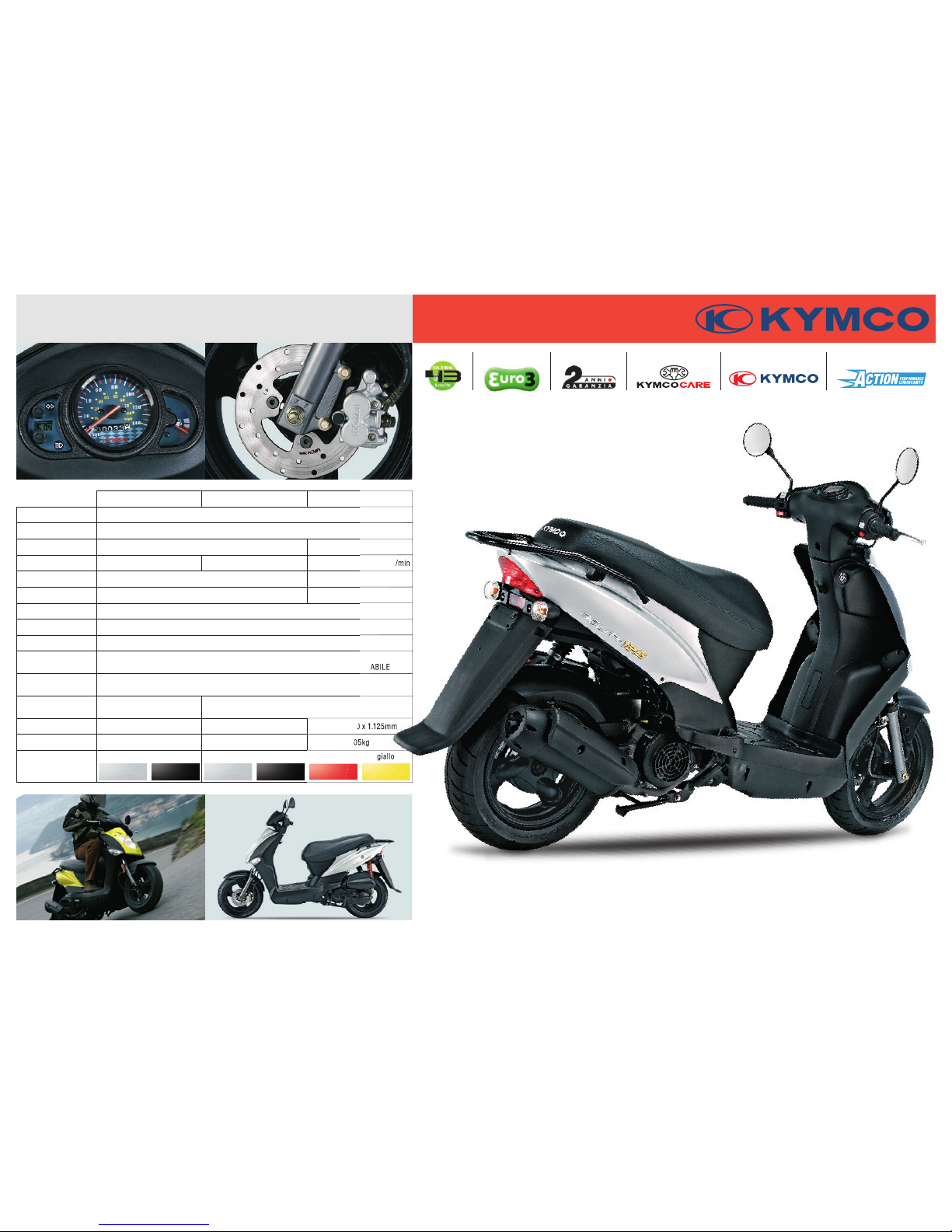
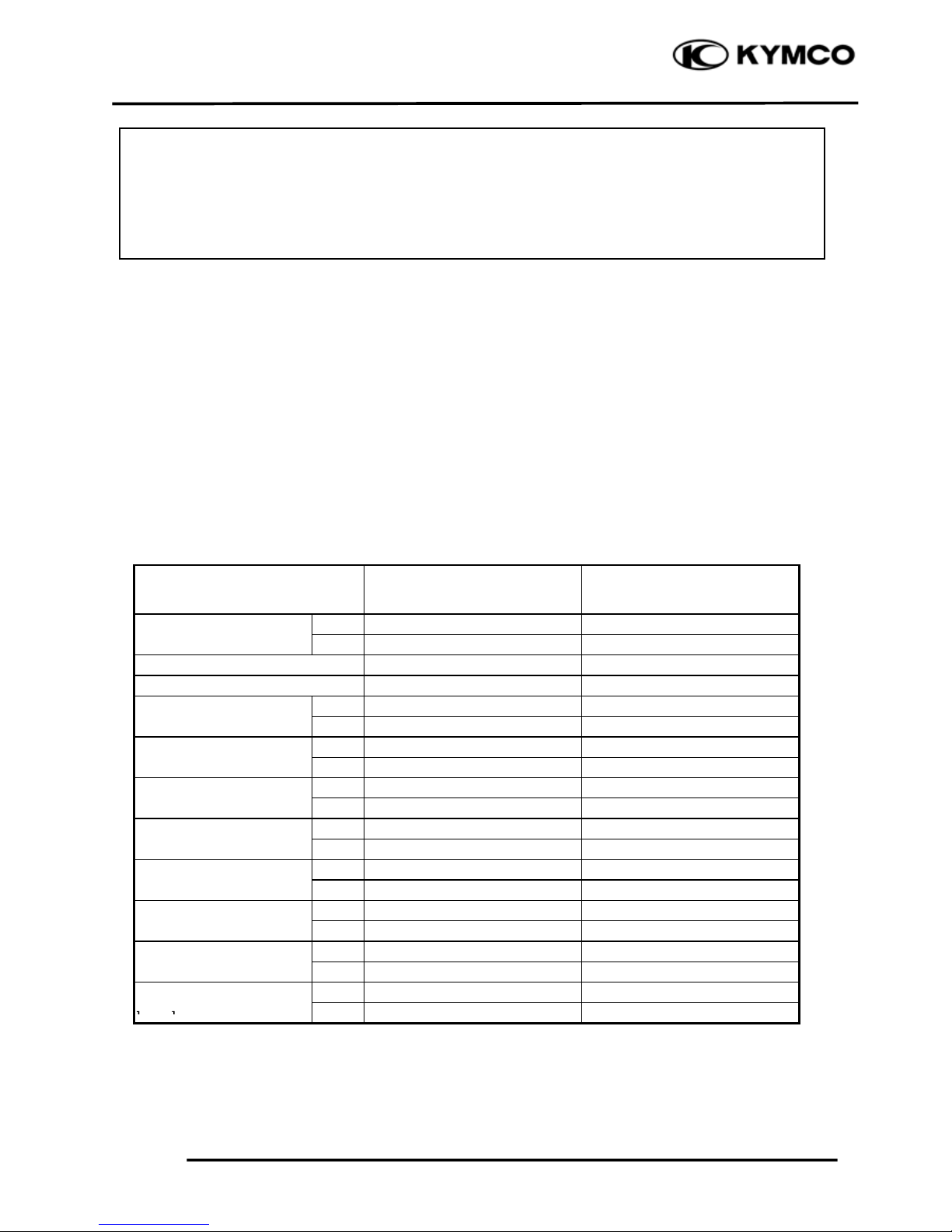
50 4T R10 50 4T R12 125
MOTORE MONOCIL INDRICO ORIZZO NTALE 4 TEMPI
RAFF REDDAMENTO ARIA FOR ZATA
CILINDR ATA 49cc 125cc
POTEN ZA
2,4kW (3 ,3CV) a 8.50 0 giri/min 2,4kW (3 ,3CV) a 7.500 giri /min 6,9kW (9,4 CV) a 7.500 giri/ min
COPPIA 3,2 Nm a 7.000 gir i 9,6 Nm a 6.50 0 giri
EMISSIO NI EURO 2 EURO 3
AVVIA MENTO E LETTRICO E K ICK STARTER
FRIZION E CE NTRIFUGA AU TOMATICA A SECC O
TRAS MISSIONE CINGHIA T RAPEZOIDA LE - INGRANA GGI
SOSPEN SIONI
ANT. FORC ELLA TELESC OPICA IDRAULI CA ø 31
POST. MONO BRACCIO OSCIL LANTE AM MORTIZZATO RE IDRAULICO RE GOLABILE
FRENI
ANT. DISCO ø 180mm
POST. TAMBUR O ø 110mm
PNEUMAT ICI
ANT. - POST. 90 /90-10
ANT. 120/ 70-12
POST. 130/ 70-12
DIMENSIO NE 1.830 x 69 0 x 1.070mm 1.830 x 69 0 x 1.130mm 1.835 x 690 x 1.125mm
MASS A 8 4kg 92kg 105kg
COLORI argent o nero argent o nero rosso giallo
giallo
Agility 50 - 125
2616-0 40407KYMCO S I RISERVA DI APPO RTARE VARIAZ IONI TECNIC HE, ESTET ICHE O DI ALTRA N ATURA SENZ A L’OBBLIGO DI ALCU N PREAVVIS O.
KYMCO RACC OMANDA2 ANNI DI GAR ANZIA 1 ANNO DI ASS ISTENZA CREDITO PERSONA LIZZATO
S e r v i z i F i n a n z i a r i
SCOOTER TARGATICICLOMOTO RI 4T
Page 3
AGILITY 50
PREFACE
This Service Manual describes the
technical features and servicing
procedures for the KYMCO AGILITY
50
Section 1 contains the precautions for all
operations stated in this manual. Read
them carefully before starting any
operation.
Section 2 is the removal/installation
procedures for the frame covers which
are subject to higher removal/installation
frequency during maintenance and
servicing operations.
Section 3 describes the inspection/
adjustment procedures, safety rules and
service information for each part, starting
from periodic maintenance.
Sections 6 through 17 give instructions
for disassembly, assembly and inspection
of engine, chassis frame and electrical
equipment.
Most sections start with an assembly or
system illustration and troubleshooting
for the section. The subsequent pages
give detailed procedures for the section.
KWANG YANG MOTOR CO., LTD.
OVERSEAS SALES DEPARTMENT
OVERSEAS SERVICE SECTION
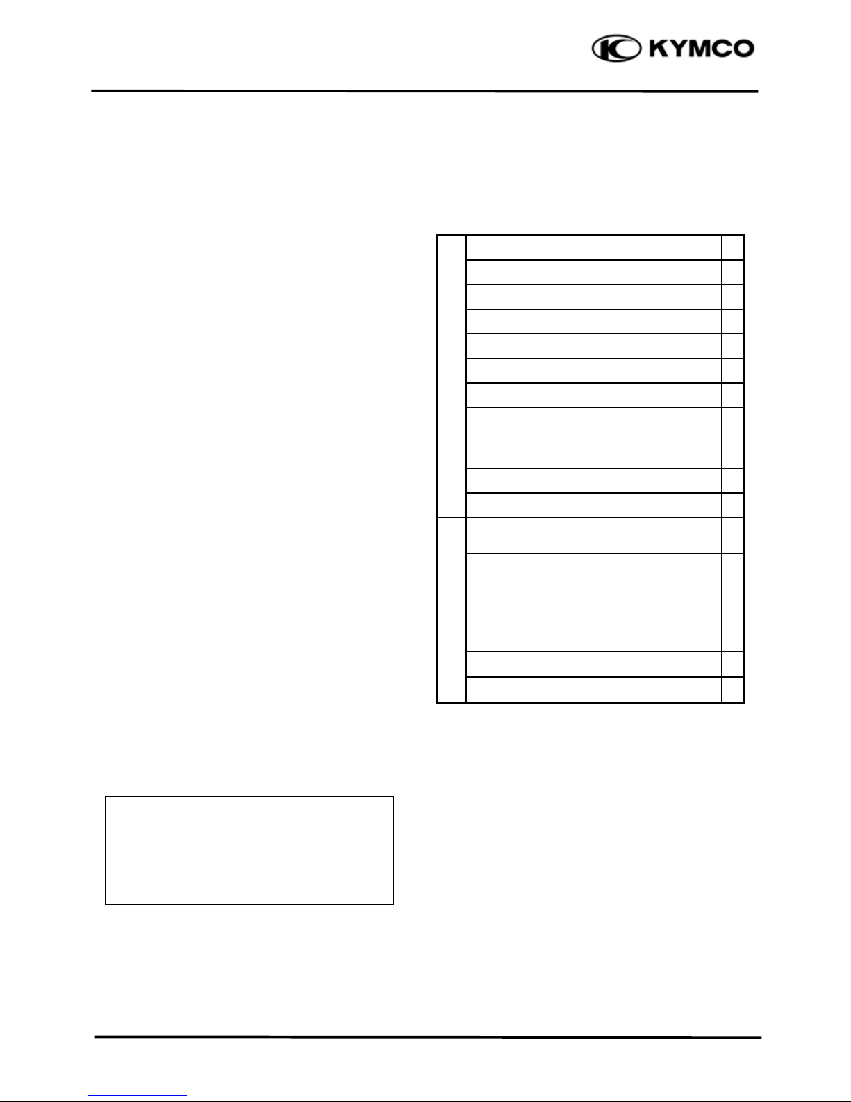
TABLE OF CONTENTS
GENERAL INFORMATION 1
FRAME COVERS/EXHAUST MUFFLER 2
INSPECTION/ADJUSTMENT 3
LUBRICATION SYSTEM 4
FUEL SYSTEM 5
ENGINE REMOVAL/INSTALLATION 6
CYLINDER HEAD/VALVES 7
CYLINDER/PISTON 8
ENGINE
DRIVE AND DRIVEN PULLEYS/KICK
STARTER
9
FINAL REDUCTION 10
CRANKCASE/CRANKSHAFT 11
FRONT WHEEL/FRONT BRAKE/
FRONT SUSPENSION
12
CHASSIS
REAR WHEEL /REAR BRAKE /REAR
SUSPENSION
13
BATTERY/CHARGING SYSTEM/A.C.
GENERATOR
14
IGNITION SYSTEM 15
STARTING SYSTEM 16
ELECTRICAL
EQUIPMEN
T
LIGHTS/INSTRUMENTS/SWITCHES 17
Our company reserves the right to
make any alteration in the design.
The information and contents included
in this manual may be different from
the motorcycle in case specifications
are changed.
Page 4
1. GENERAL INFORMATION
1-1
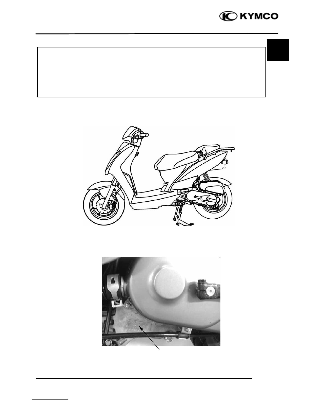
AGILITY 50
Location of Engine Serial Numbe
r
1
ENGINE SERIAL NUMBER
1
ENGINE SERIAL NUMBER...................1- 1 LUBRICATION POINTS .......................1-13
SPECIFICATIONS ...................................1- 2 CABL E & H A R N E S S R O UTI N G............1-15
SERVICE PRECAUTIONS......................1- 3 WIRING DIAGRAM................................1-20
TORQUE VALUES..................................1-11 TROUBLESHOOTUNG ..........................1-21
SPECIAL TOOLS.....................................1-12
AGILITY 50
Page 5
1. GENERAL INFORMATION
1-2
AGILITY 50
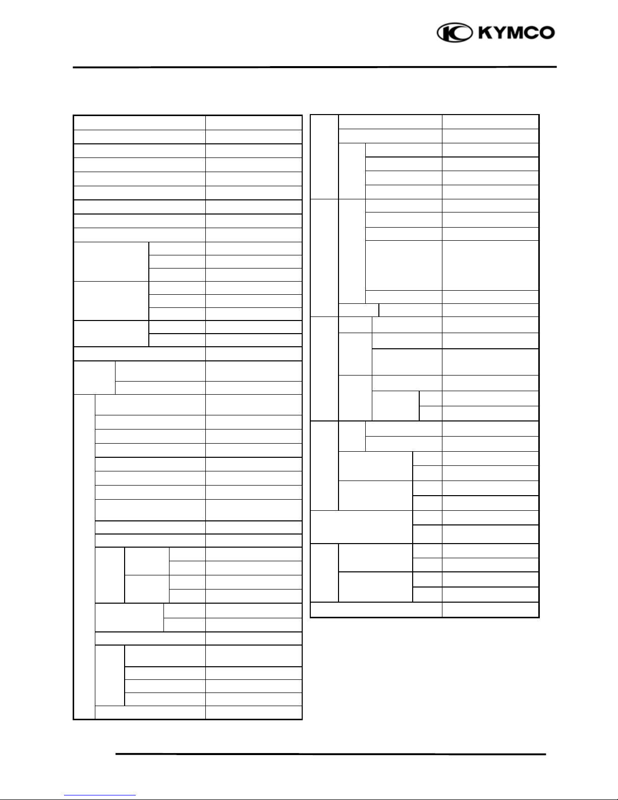
SPECIFICATIONS
Motorcycle Name & Type AGILITY 50
Name & Model No. KG10SA
Overall length (mm) 1830
Overall width (mm) 690
Overall height (mm) 1130
Wheel base (mm) 1325
Engine type O.H.C.
Displacement 49.5cc
Fuel Used 92# nonleaded gasoline
Front wheel 37.5
Net weight (kg) Rear wheel 55
Total 92.5
Front wheel 38
Gross weight(kg) Rear wheel 59
Total 97
Front wheel 120/70 -12 56J
Tires
Rear wheel 130/70 -12 56J
Ground clearance (mm) 112
Perform-
Braking distance (m)
4 (Initial speed
20km/h)
ance
Min. turning radius (m) 1.99
Starting system
Starting motor &
kick starter
Type Gasoline, 4-stroke
Cylinder arrangement Single cylinder
Combustion chamber type Semi-sphere
Valve arrangement O.H.C.
Bore x stroke (mm) I39.0 x 41.4
Compression ratio 11
Compression pressure
(kg/cm²-rpm)
18
Max. output 3.5/7500kw/(r/min)
Max. torque 0.35/7000kg m/rpm
Open 3q
Port
Intake
Close 7q
Engine
timin
g
Open 9q
Exhaust
Close 1q
Intake 0.04
(cold) (mm)
Exhaust 0.04
Idle speed (rpm) 1700Ô100rpm
Lubrication type
Forced
p
ressure &
wet sump
Oil pump type Inner/outer rotor type
Oil filter type Full-flow filtration
Lubrication
System
Oil capacity 0.8 liter
Cooling Type Forced air cooling
Air cleaner type & No Paper element, wet
Fuel capacity 5.0 liter
Type CVK
Piston dia. (mm)
Venturi dia.(mm) I17equivalent
Carburetor
Throttle type Butterfly type
Type CDI
Ignition timing BTDC28q/4000rpm
Contact breaker Non-contact point type
Spark plug
NGK
C7HSA
Spark plug gap 0.6Д0.7mm
Battery Capacity 12V4AH
Clutch Type Dry multi-disc clutch
Type Non-stage transmission
Operation
Automatic centrifugal
type
Type Two-stage reduction
Reduction 1st
0.8-3.1
ratio
2nd
11.05
Front Caster angle 27q
Axle
Trail length
Tire pressure
Fron
t
1.75
(kg/cm²)
Rear 2.25
Turning Left 45q
angle
Right 45q
FrontDISK (180mm) brake
Brake system
type
Rear Drum (110mm) brake
Fron
t
TELESCOPE
Suspension type
Rear Unit Swing
Front 80
Shock absorber
distance
Rear
82
Frame type Under Bone
Fuel S
y
stem
Electrical E
q
ui
p
ment
I
g
nition S
y
stem
Power Drive System
Transmis-
sion Gear
Reduction
Gear
Moving Device
Damping
Device
Page 6
1. GENERAL INFORMATION
1-3
AGILITY 50
SERVICE PRECAUTIONS
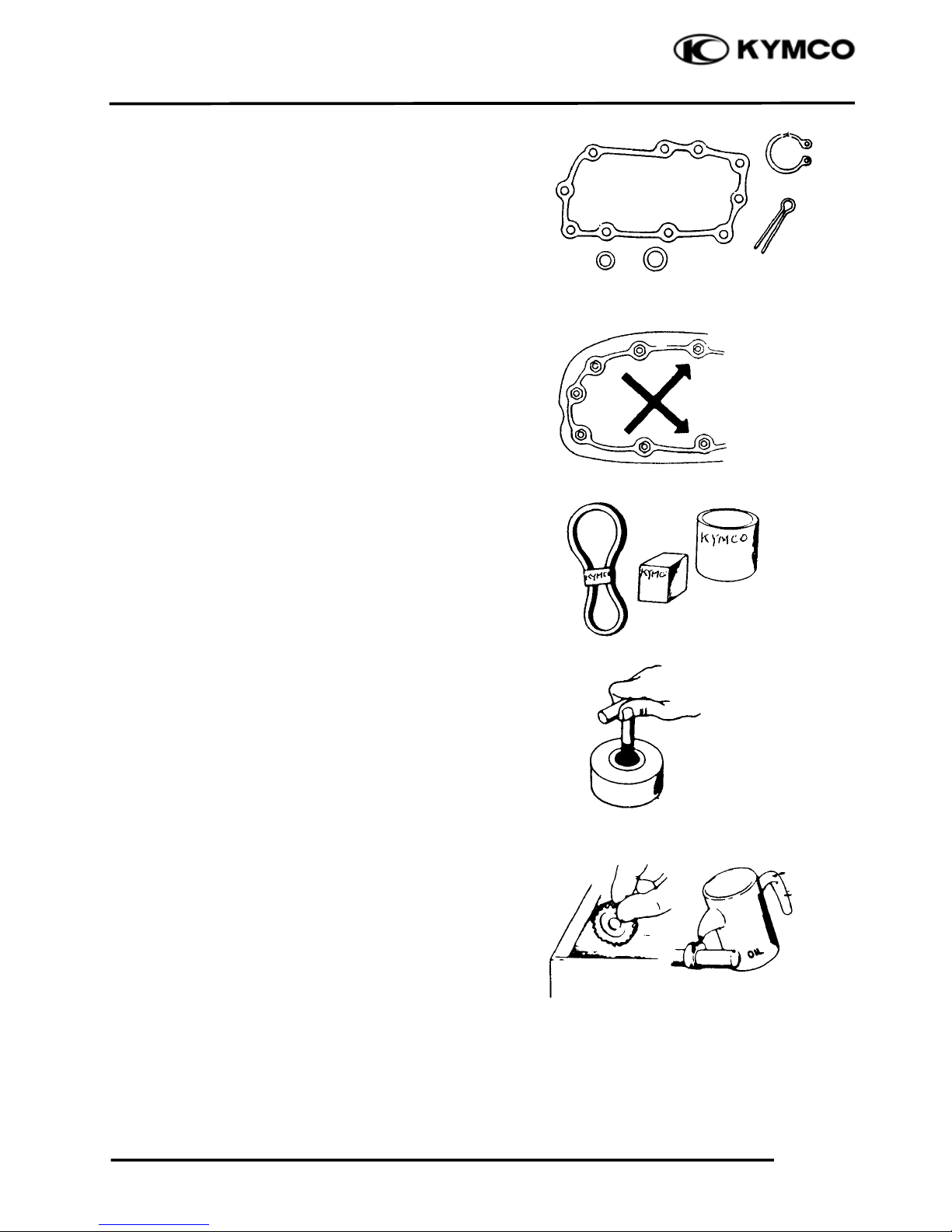
Make sure to install new gaskets, O-rings,
circlips, cotter pins, etc. when
reassembling.
When tightening bolts or nuts, begin with
larger-diameter to smaller ones at several
times, and tighten to the specified torque
diagonally.
Use genuine parts and lubricants
.
When servicing the motorcycle, be sure to
use special tools for removal and
installation.
After disassembly, clean removed parts.
Lubricate sliding surfaces with engine oil
before reassembly.
Page 7
1. GENERAL INFORMATION
1-4
AGILITY 50
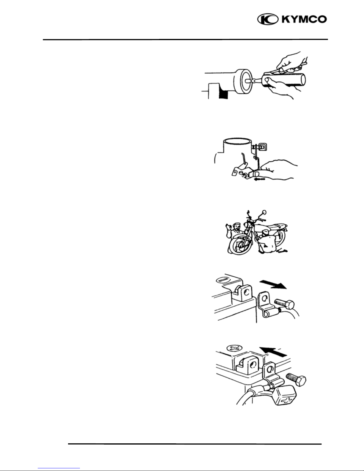
Apply or add designated greases and
lubricants to the specified lubrication
points.
After reassembly, check all parts for proper
tightening and operation.
When two persons work together, pay
attention to the mutual working safety.
Disconnect the battery negative (-) terminal
before operation.
When using a spanner or other tools, make
sure not to damage the motorcycle surface.
After operation, check all connecting
points, fasteners, and lines for proper
connection and installation.
When connecting the battery, the positive
(+) terminal must be connected first.
After connection, apply grease to the
battery terminals.
Terminal caps shall be installed securely.
Page 8
1. GENERAL INFORMATION
1-5
AGILITY 50
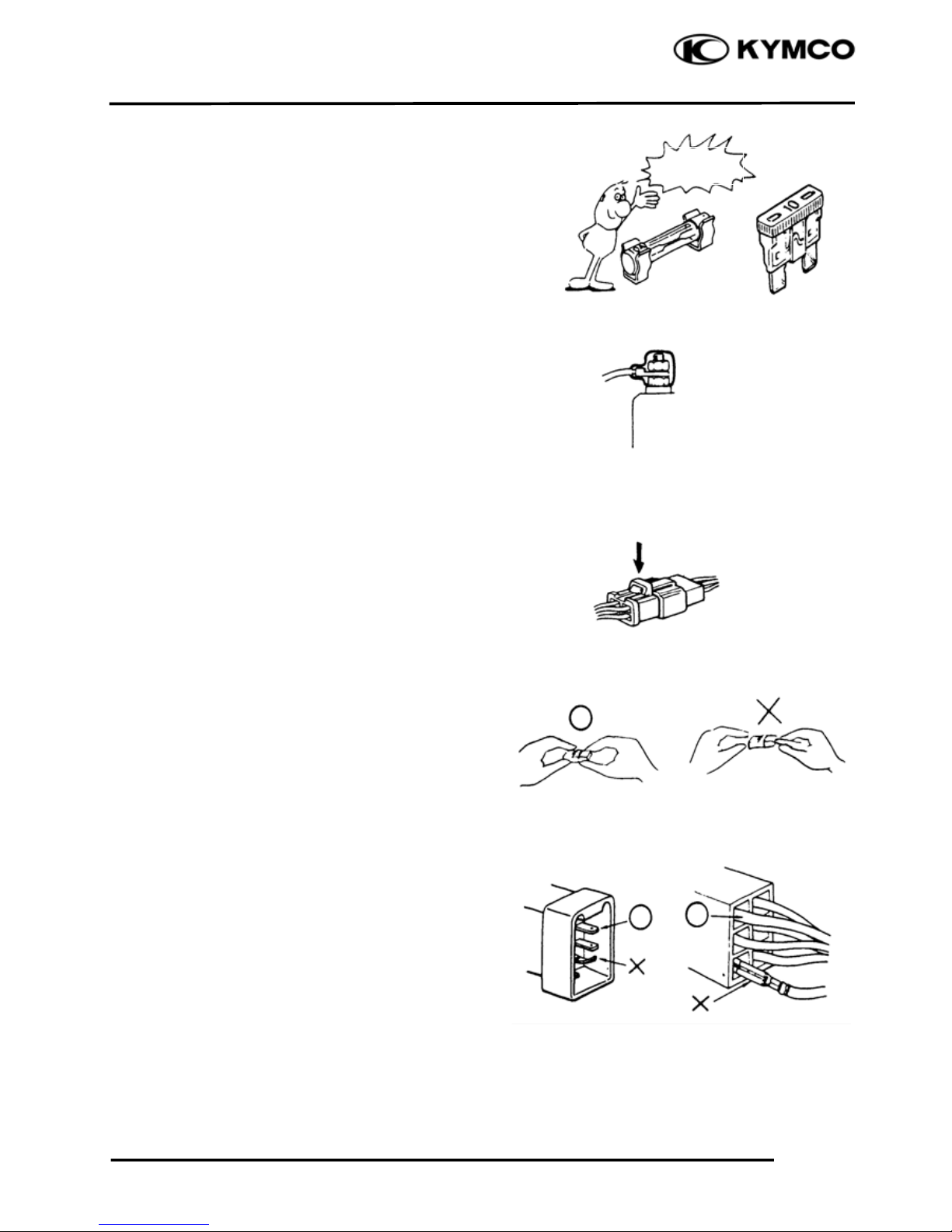
If the fuse is burned out, find the cause and
repair it. Replace it with a new one
according to the specified capacity.
After operation, terminal caps shall be
installed securely.
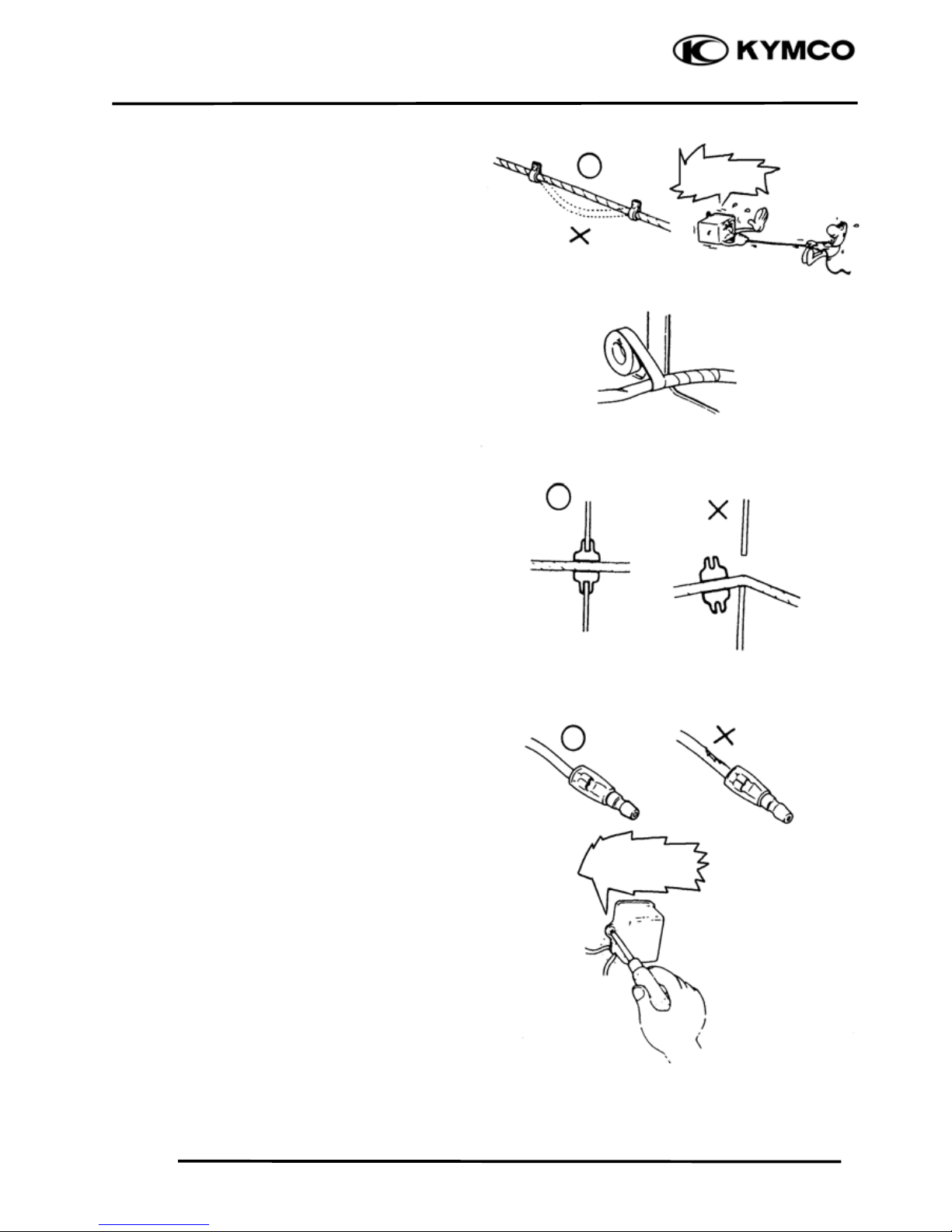
When taking out the connector, the lock on
the connector shall be released before
operation.
Hold the connector body when connecting
or disconnecting it.
Do not pull the connector wire.
Check if any connector terminal is bending,
protruding or loose.
Confir
m
Capacity
Page 9
1. GENERAL INFORMATION
1-6
AGILITY 50
The connector shall be inserted
completely.
If the double connector has a lock, lock
it at the correct position.
Check if there is any loose wire.
Before connecting a terminal, check for
damaged terminal cover or loose
negative terminal.
Check the double connector cover for
proper coverage and installation.
Insert the terminal completely.
Check the terminal cover for proper
coverage.
Do not make the terminal cover opening
face up.
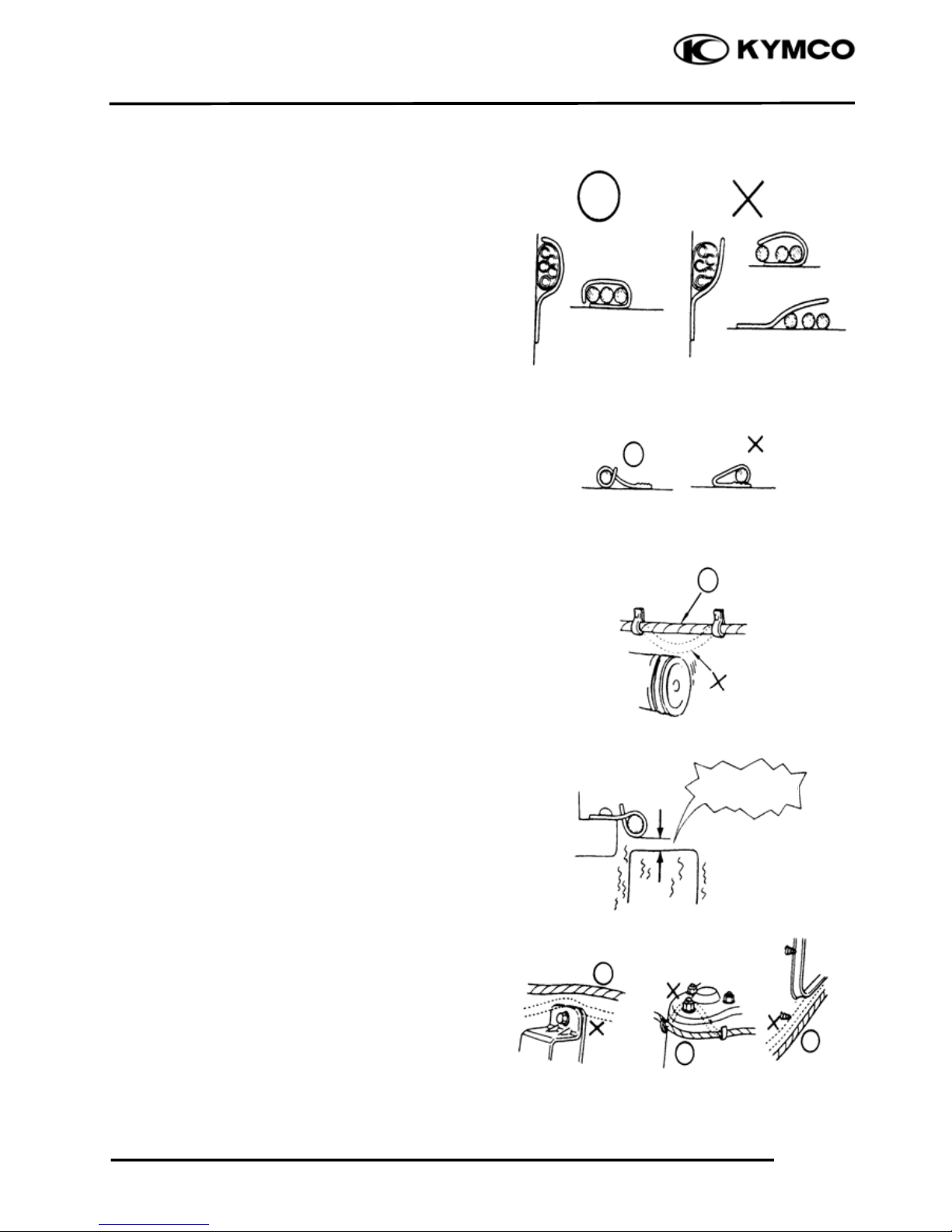
Secure wire harnesses to the frame with
their respective wire bands at the
designated locations.
Tighten the bands so that only the insulated
surfaces contact the wire harnesses.
Snapping!
Page 10
1. GENERAL INFORMATION
1-7
AGILITY 50
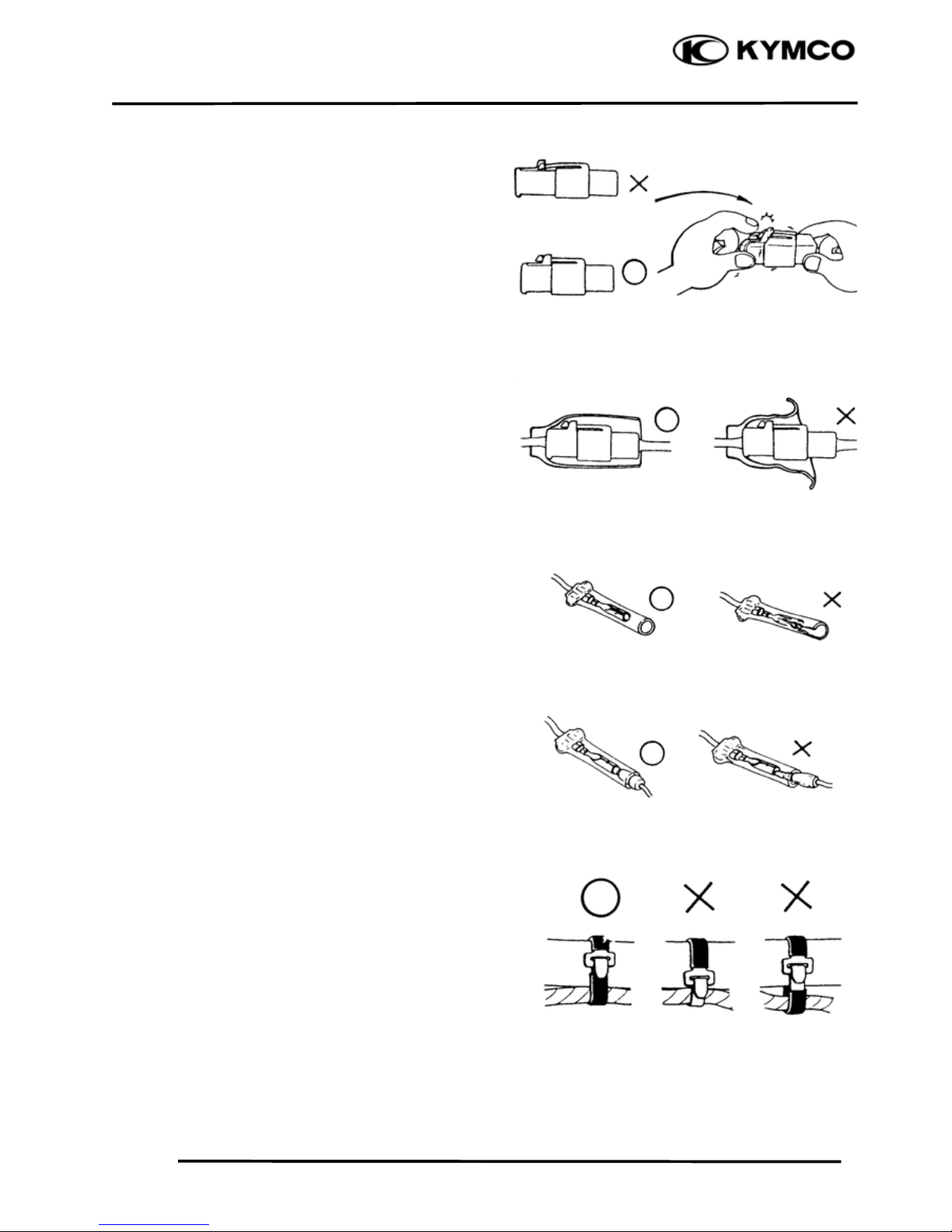
After clamping, check each wire to make
sure it is secure.
.
Do not squeeze wires against the weld or
its clamp
After clamping, check each harness to
make sure that it is not interfering with any
moving or sliding parts.
When fixing the wire harnesses, do not
make it contact the parts which will
generate high heat.
Route wire harnesses to avoid sharp edges
or corners. Avoid the projected ends of
bolts and screws.
Route wire harnesses passing through the
side of bolts and screws. Avoid the
projected ends of bolts and screws.
N
o Contact !
Page 11
1. GENERAL INFORMATION
1-8
AGILITY 50
Route harnesses so they are neither
pulled tight nor have excessive slack.
.
Protect wires and harnesses with electrical
tape or tube if they contact a sharp edge or
corner
When rubber protecting cover is used to
protect the wire harnesses, it shall be
installed securely.
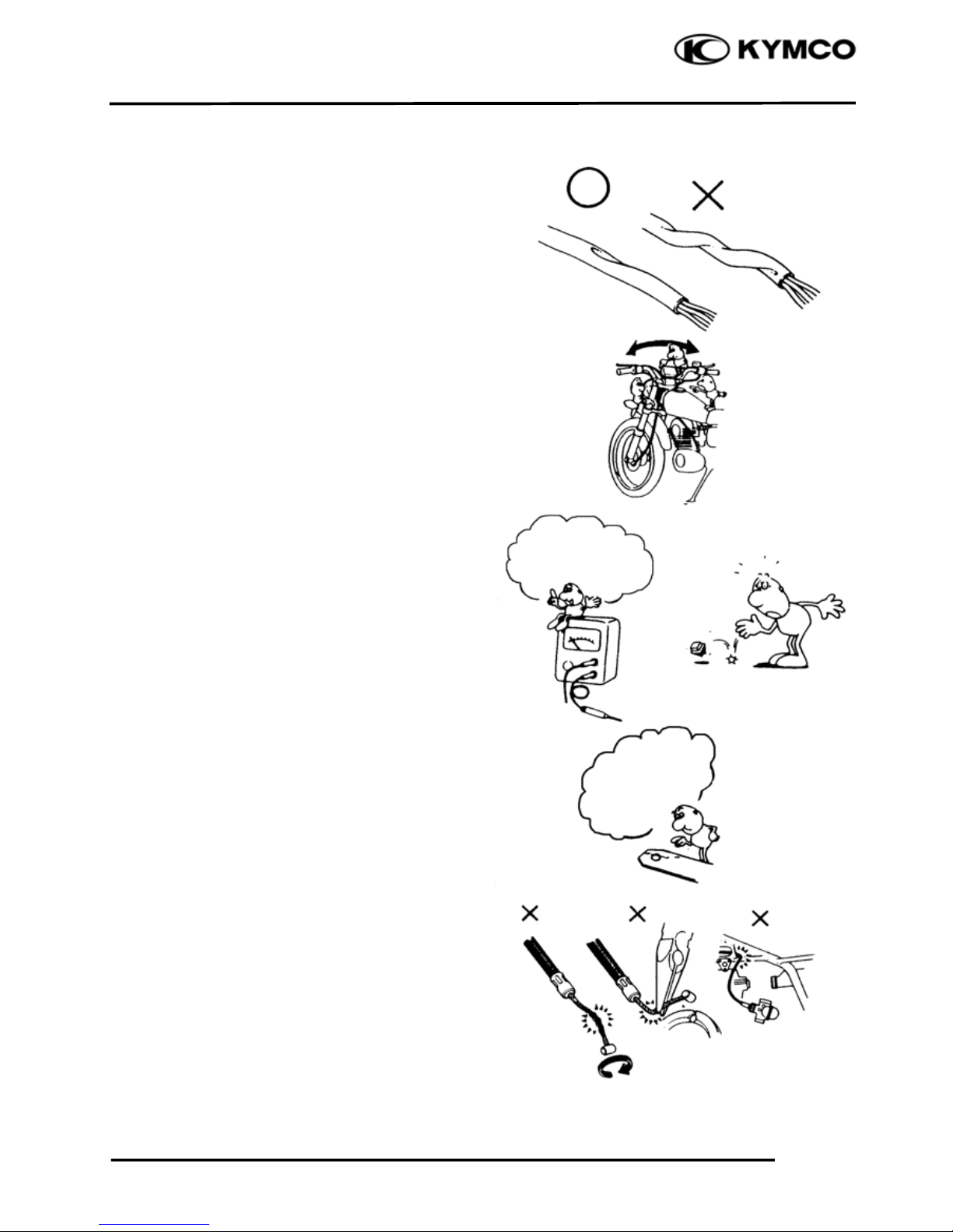
Do not break the sheath of wire.
If a wire or harness is with a broken sheath,
repair by wrapping it with protective tape
or replace it.
When installing other parts, do not press or
squeeze the wires.
Do not pull
too ti
g
ht!
Do not press o
r
squeeze the wire.
Page 12
1. GENERAL INFORMATION
1-9
AGILITY 50
After routing, check that the wire harnesses
are not twisted or kinked.
Wire harnesses routed along with
handlebar should not be pulled tight, have
excessive slack or interfere with adjacent
or surrounding parts in all steering
positions.
When a testing device is used, make sure to
understand the operating methods
thoroughly and operate according to the
operating instructions.
Be careful not to drop any parts.
When rust is found on a terminal, remove
the rust with sand paper or equivalent
before connecting.
Do not bend or twist control cables.
Damaged control cables will not operate
smoothly and may stick or bind.
Do you understand
the instrument? Is
the instrument set
correctly?
Remove Rust !
Page 13
1. GENERAL INFORMATION
1-10
AGILITY 50
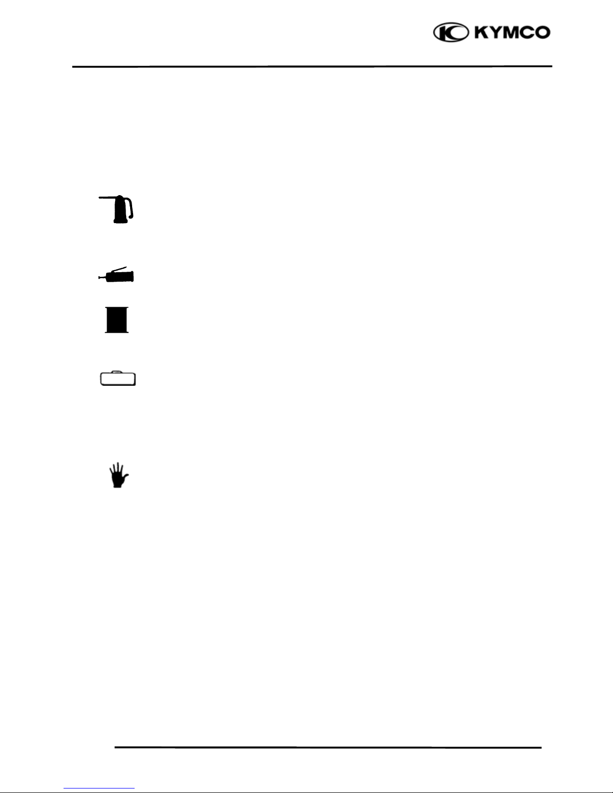
Symbols:
The following symbols represent the
servicing methods and cautions included in
this service manual.
: Apply engine oil to the
specified points. (Use
designated engine oil for
lubrication.)
: Apply grease for lubrication.
: Transmission Gear Oil (90#)
: Use special tool.
: Caution
: Warning
(Ö12-3) :Refer to page 12-3.
Engine Oil
Grease
Gear Oil
Special
*
Page 14
1. GENERAL INFORMATION
1-11
AGILITY 50
TORQUE VALUES
STANDARD TORQUE VALUES
Ite
m
Torque (kg-m
)
Ite
m
Torque (kg-m
)
5mm bolt, nut
6mm bolt, nut
8mm bolt, nut
10mm bolt, nut
12mm bolt, nut
0.45-0.6
0.6-1.2
1.8-2.5
3.0-4.0
5.0-6.0
5mm screw
6mm screw, SH bolt
6mm flange bolt, nut
8mm flange bolt, nut
10mm flange bolt, nut
0.35-0.5
0.7-1.1
1.0-1.4
2.4-3.0
3.5-4.5
Torque specifications listed below are for important fasteners.
ENGINE
Item Q‘ty Thread dia.(mm) Torque (kg-m) Remarks
Cylinder head bolt A
Cylinder head bolt B
Oil filter screen cap
Exhaust muffler lock bolt
Cylinder head flange nut
Valve adjusting lock nut
Cam chain tensioner slipper bolt
Oil bolt
Clutch outer nut
Clutch drive plate nut
Starter motor mounting bolt
Oil pump bolt
Drive face nut
Spark plug
A.C. generator stator bolt
Cam chain tensioner bolt
2
4
1
2
4
2
1
1
1
1
2
3
1
1
2
1
6
6
30
6
7
3
8
8
10
28
6
4
10
10
6
6
0.7-1.1
0.7-1.1
1.0-2.0
0.7-1.1
1.2-1.6
0.07-0.09
0.4-0.7
1.1-1.5
3.5-4.5
5.0-6.0
0.8-1.2
0.1-0.3
5.5-6.5
1.0-1.4
0.8-1.2
0.8-1.2
Double end bolt
Double end bolt
Apply oil to
threads
FRAME
Item Q‘ty Thread dia.(mm) Torque (kg-m) Remarks
Steering stem lock nut
Front axle nut
Rear axle nut
Rear shock absorber upper bolt
Rear shock absorber lower bolt
Speedometer cable set screw
Rear shock absorber lock nut
1
1
1
1
1
1
1
25.4
10
14
10
8
5
8
8.0-12.0
5.0-7.0
11.0-13.0
4.0-5.0
2.0-3.0
0.45-0.6
3.0-3.6
U-nut
U-nut
U-nut
Apply locking agent
Page 15
1. GENERAL INFORMATION
1-12
AGILITY 50
SPECIAL TOOLS
Tool Name Tool No. Remarks Ref. Page
10-3
10-4Bearing puller 10.12.15.18 mm E037 10.12.15.18mm bearing
12-6
Bushing remover L E032 11102 bush engine hanger rubber
Bushing remover S EO19 11203 bush rear cushion under rubber
Crankshaft bearing puller E030 91005 radial bearing
Crankshaft protector E029 13000 crankshaft comp 12mm.14mm
Clutch spring compressor E027 2301a driven pully assy
9-9
9-12
Cushion assemble & disassemble
tool
F004 52400 cushion assy 13-4
Flywheel holder E017
31110 fl
y
wheel comp.2310a pully ass
y
driven
9-5
9-9
9-13
14-7
14-9
Flywheel puller E002 Left hand thread 27mm
14-7
Long socket wrench 32mm 8angle F002 50306 steering stem
12-21
12-22
Oil seal & bearing installer E014 Oil seal & bearing install
Tool boox E033 Special tools storage
Tappet adjuster E036 90012 screw tappet 3-5
7-7
Valve spring compressor E038 Valve spring
7-8
Page 16

1. GENERAL INFORMATION
1-13
AGILITY 50
LUBRICATION POINTS
ENGINE
Lubrication Points Lubricant
Valve guide/valve stem movable part
Cam lobes
Valve rocker arm friction surface
Cam chain
Cylinder lock bolt and nut
Piston surroundings and piston ring grooves
Piston pin surroundings
Cylinder inside wall
Connecting rod/piston pin hole
Connecting rod big end
Crankshaft R/L side oil seal
Starter reduction gear engaging part
Countershaft gear engaging part
Final gear engaging part
Bearing movable part
O-ring face
Oil seal lip
xGenuine KYMCO Engine Oil (SAE15W-40)
xAPISG Engine Oil
Starter idle gear
Friction spring movable part/shaft movable part
Shaft movable grooved part
Kick starter spindle movable part
High-temperature resistant grease
A.C. generator connector
Transmission case breather tube
Adhesive
Page 17
1. GENERAL INFORMATION
1-14
AGILITY 50
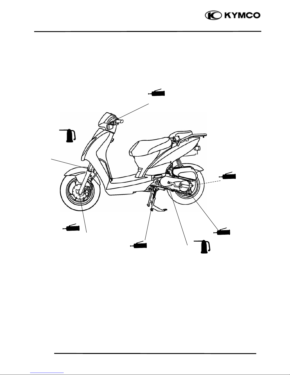
FRAME
The following is the lubrication points for the frame.
Use general purpose grease for parts not listed.
Apply clean engine oil or grease to cables and movable parts not specified.
This will avoid abnormal noise and rise the durability of the motorcycle.
Rear Wheel Bearings
Main Stand Pivot
Speedometer Gear/ Front Wheel
Bearings/ Brake Cam/ Anchor Pin
/Front Shock Absorber Lower
Mount Bushings/Pivot
Grease
Grease
Grease
Engine Oil
Rear Brake Cable
Brake Cam
/
Anchor Pin
Grease
Grease
Front Brake Leve
r
Pivot
Front Brake Cable
/
Speedometer Cable/
Throttle Cable
Engine/ Oil
Page 18
1. GENERAL INFORMATION
1-15
AGILITY 50
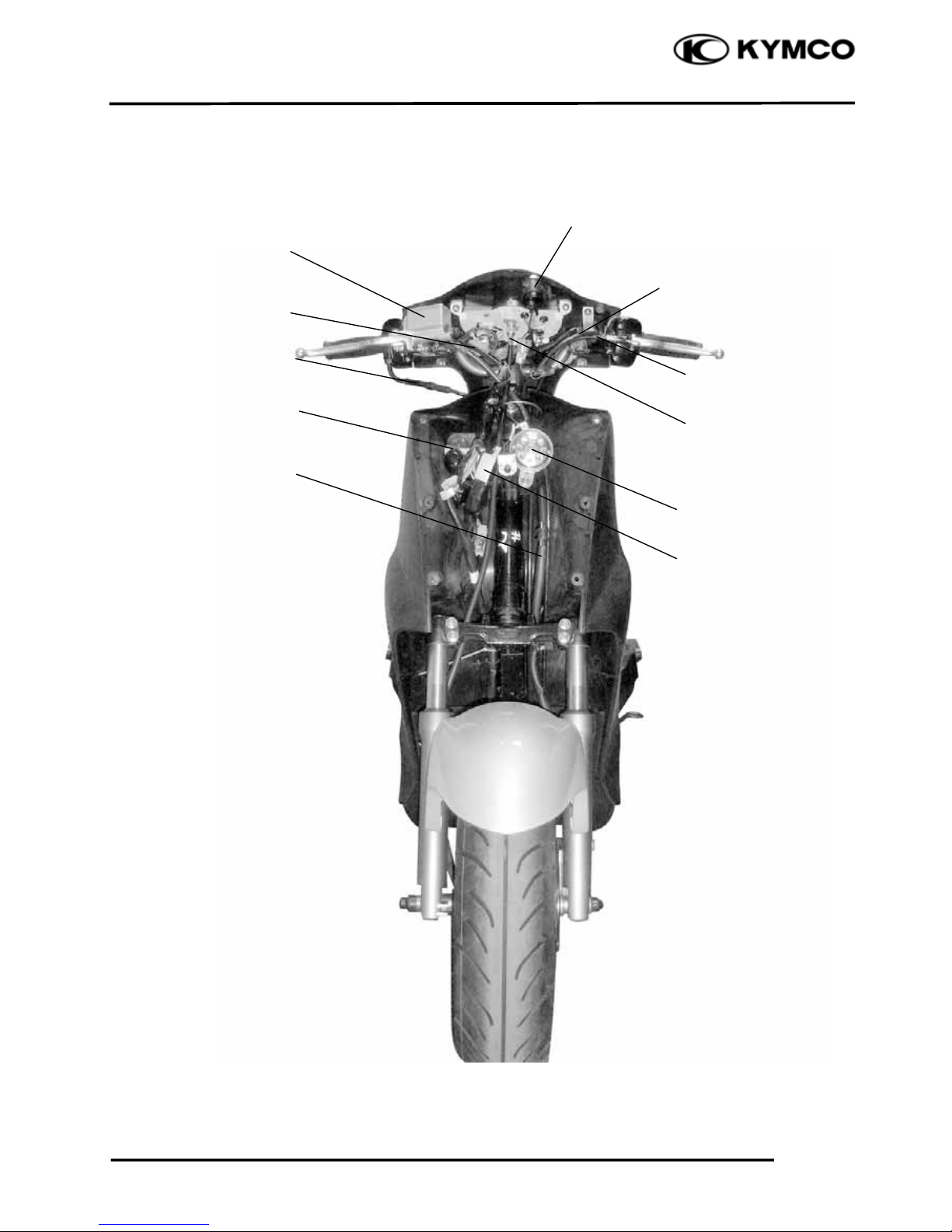
CABLE & HARNESS ROUTING
Front Stop Switch Wire
Rear Stop Switch Wire
Throttle Cable
Regulator/Rectifie
r
Rear Brake Cable
Speedometer Cable
Horn
Ignition Switch
Winke
r
Front Brake Fluid Tube
Brake Master Cylinde
r
Page 19
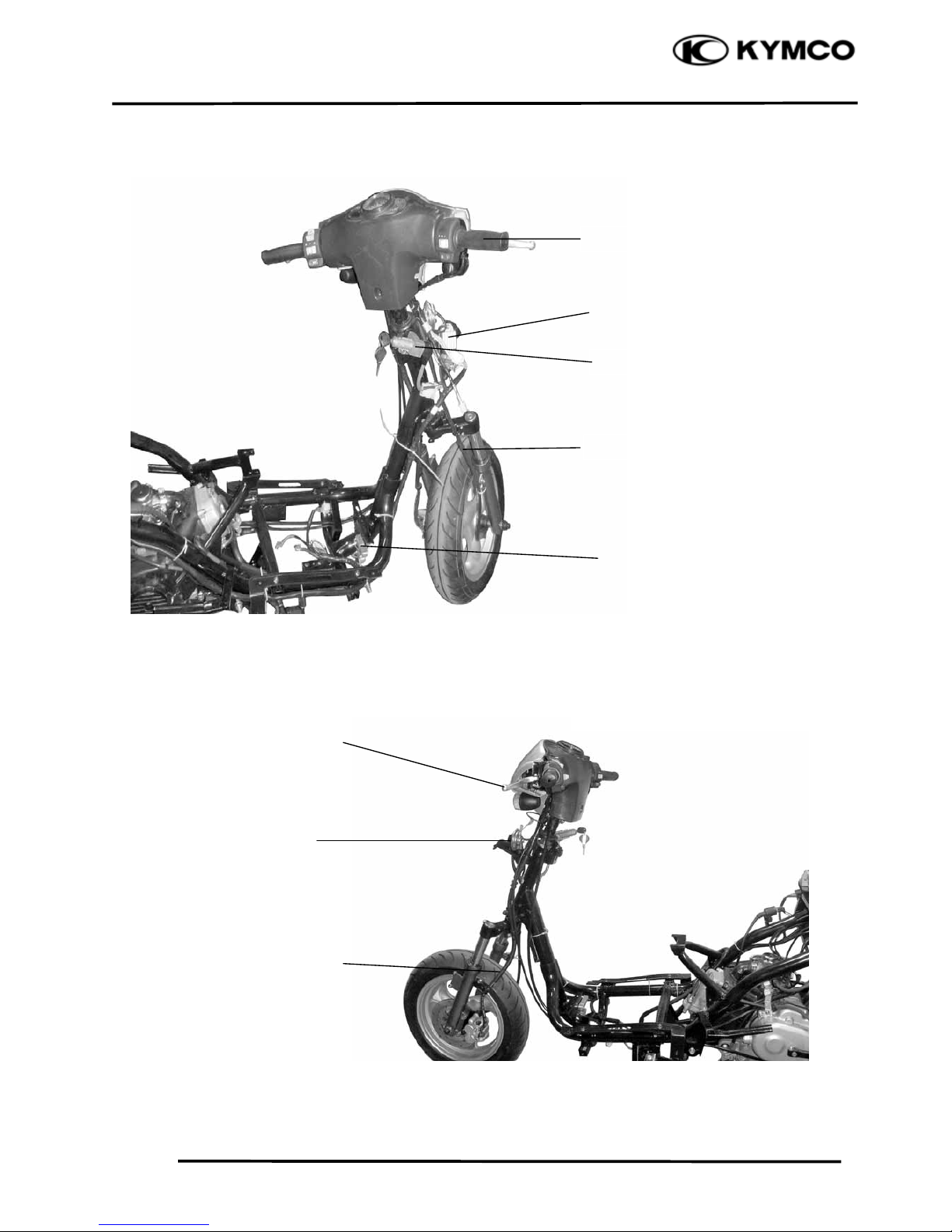
1. GENERAL INFORMATION
1-16
AGILITY 50
Regulator/Rectifie
r
Speedometer Cable
Ignition Switch
Throttle Grip
Rear Brake Leve
r
Front Brake Fluid Tube
Headlight Resisto
r
Horn
Page 20
1. GENERAL INFORMATION
1-17
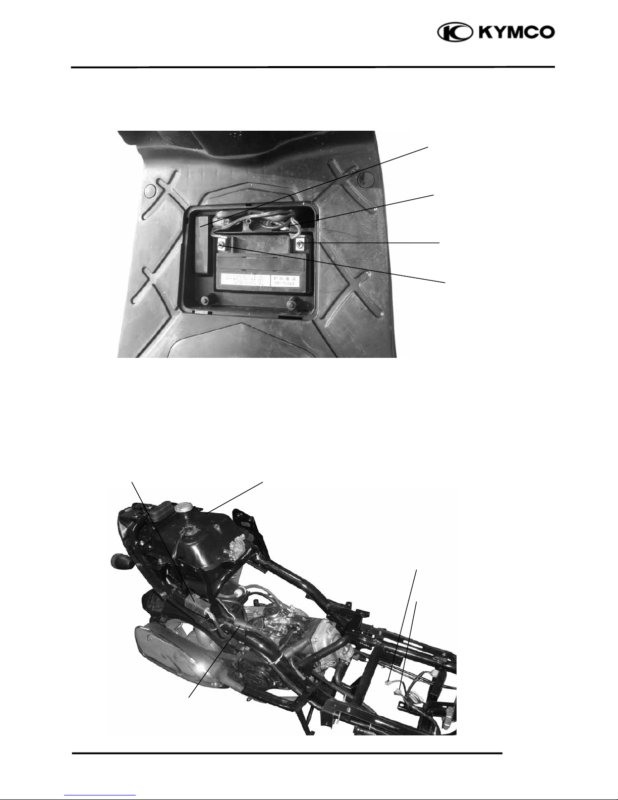
AGILITY 50
Starter Relay
Fuse
Battery (+) Cable
Battery (-) Cable
CDI Unit
Battery (+) Cable
Battery (-) Cable
Fuel Tan
k
Ignition Coil
Page 21
1. GENERAL INFORMATION
1-18
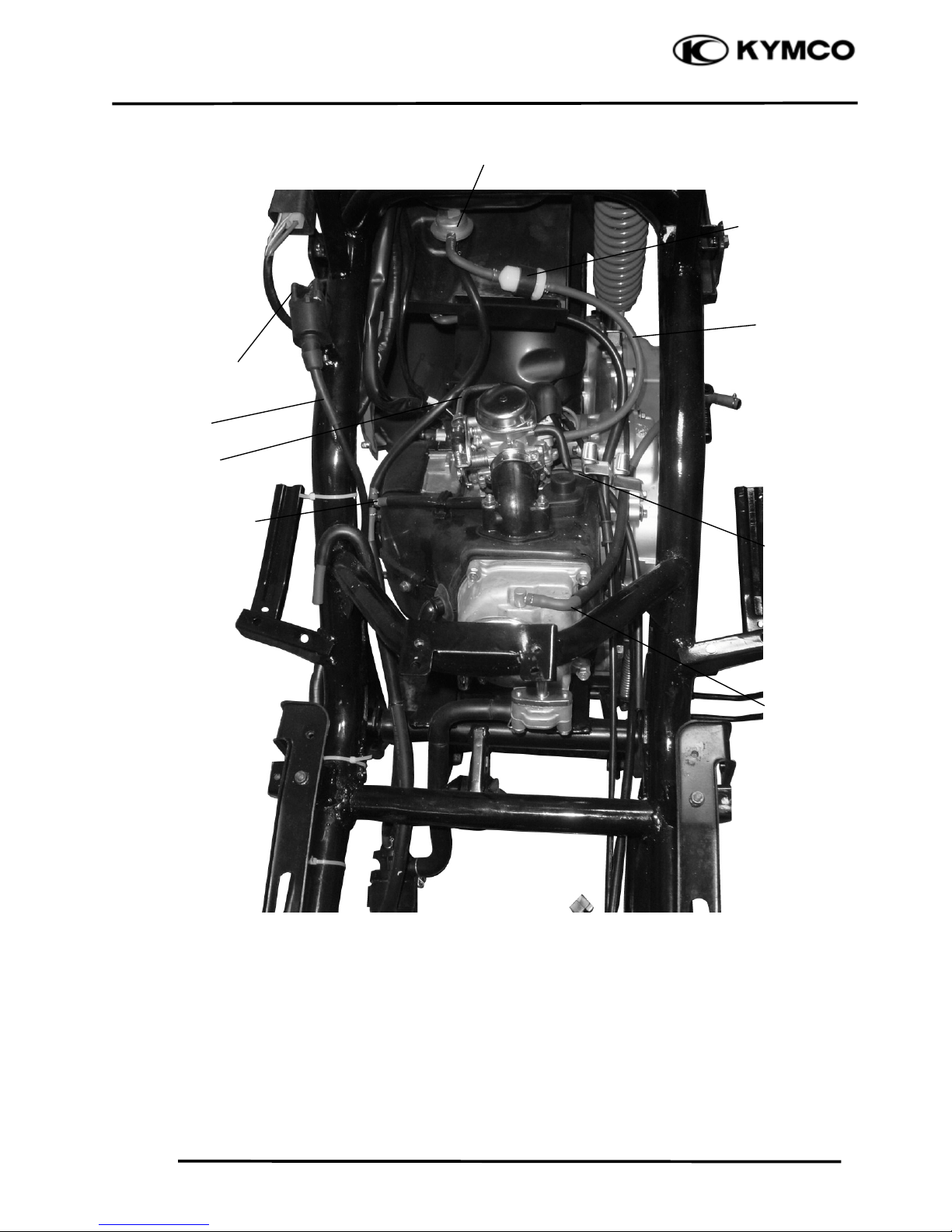
AGILITY 50
Throttle Cable
Vacuum Tee
Carbureto
r
Overflow Tube
Fuel Tube
Crankcase Breathe
r
Tube
Ignition Coil
Primary Wire
Ignition Wire
Fuel Filte
r
Auto Cock Assy Fuel
Page 22

1. GENERAL INFORMATION
1-19
AGILITY 50
Throttle Cable
Fuel Tube
Vacuum Tube
Auto Bystarte
r
Crankcase Breathe
r
Tube
Ignition Coil
Wire
Crankcase Breathe
r
Tube
Throttle Cable
Vacuum Tube
Fuel Unit
Reed Valve
Secondary Ai
r
Inlet Tube
Air Injection
Cut-off
Valve
Page 23
1. GENERAL INFORMATION
1-20
AGILITY 50
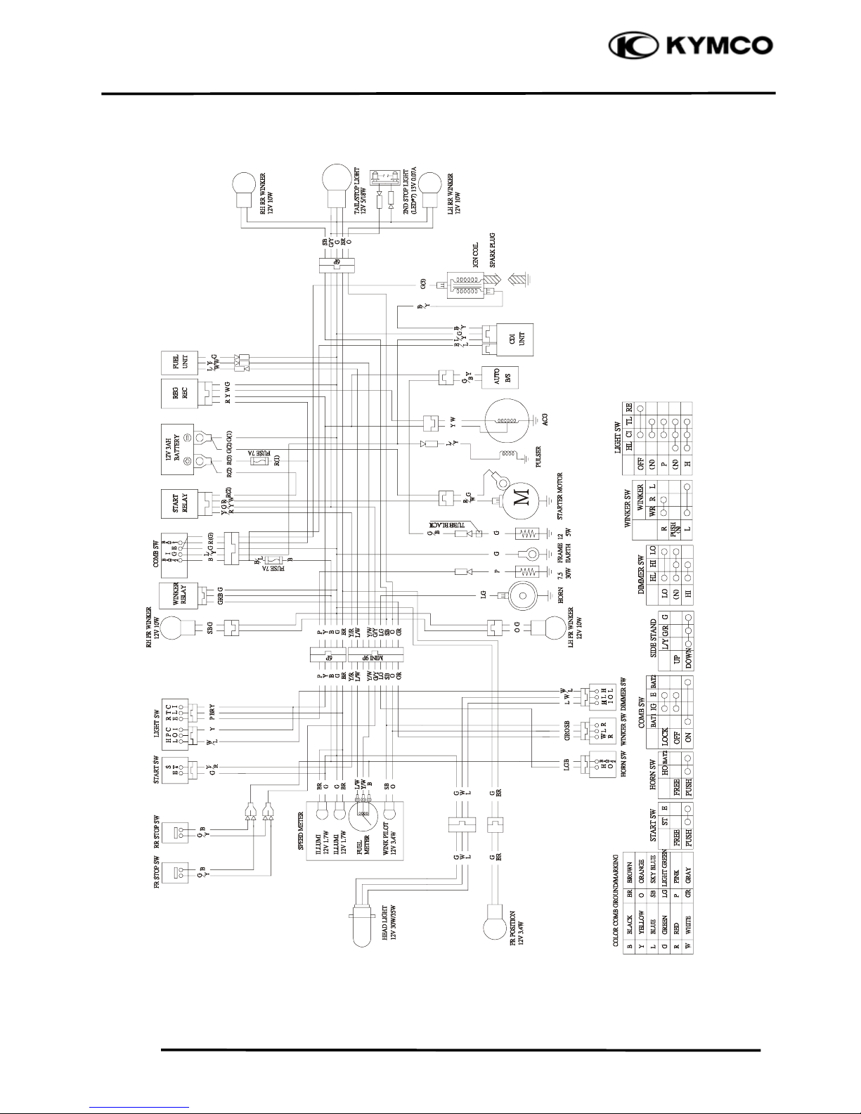
WIRING DIAGRAM
Page 24
1. GENERAL INFORMATION
1-21
AGILITY 50
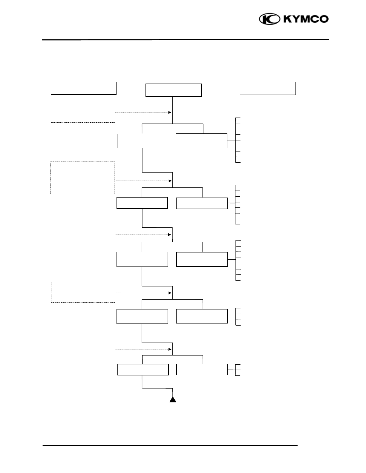
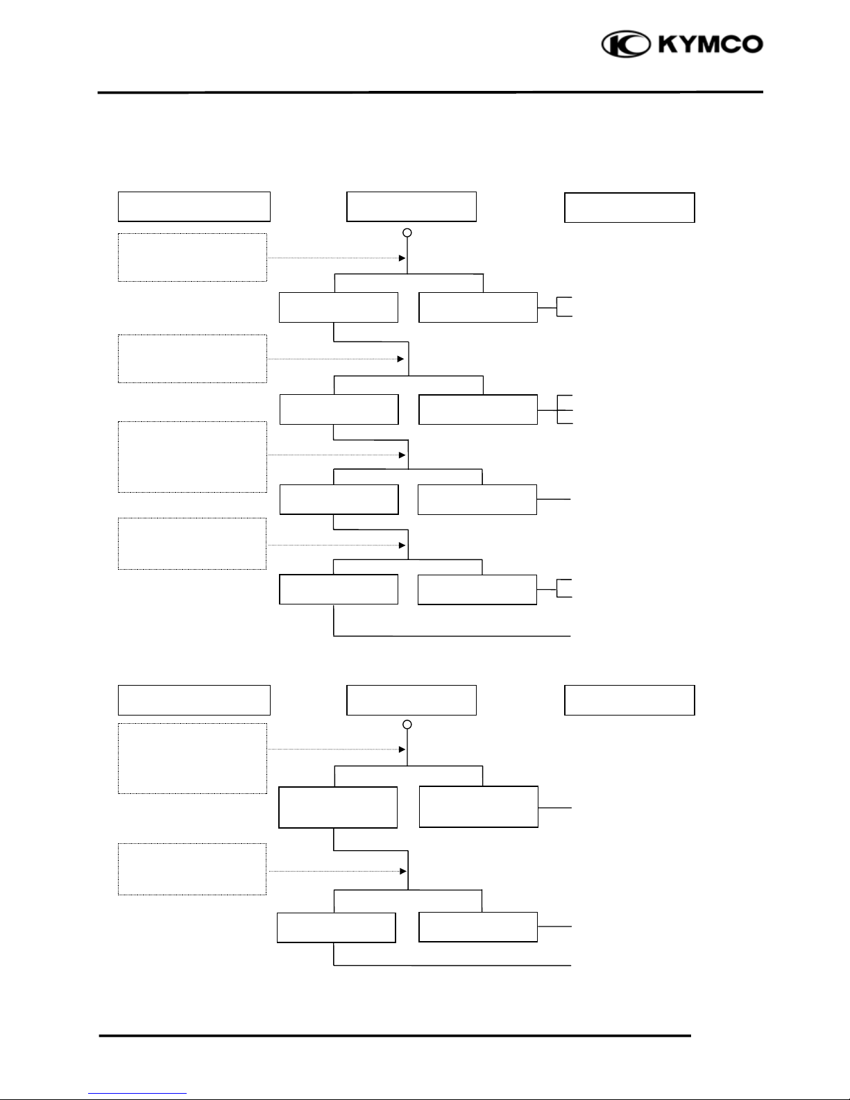
TROUBLESHOOTING
ENGINE WILL NOT START OR IS HARD TO START
Empty fuel tank
Clogged fuel line between fuel
tank and carburetor
Clogged float oil passage
Clogged fuel tank cap breather
hole
Clogged fuel filter
Clogged fuel strainer
Faulty auto fuel
valve
Faulty spark plug
Fouled spark plug
Faulty CDI unit
Faulty pulser coil
Broken or shorted ignition coil
Broken or shorted high-tension
wire
Faulty ignition switch
Faulty starter clutch
Valve clearance too small
Improper valve and seat contact
Worn cylinder, piston and piston
rings
Leaking cylinder head gasket
Seized valve
Improper valve timing
Faulty auto bystarter
Air leaking through intake pipe
Incorrect ignition timing
Incorrectly adjusted pilot screw
Flooded carburetor
Faulty auto bystarter
Throttle valve excessively open
Check if fuel reaches
carburetor by loosening
drain screw
Remove spark plug and
install it into spark plug
cap to test spark by
connecting it to engine
ground
Inspection/Adjustment
Probable Cause
Spark jumps
Normal
compression
Engine does no
t
fire
Weak or no spark
Low or no
compression
Engine fires bu
t
does not start
Test cylinde
r
compression
Start engine by following normal starting
p
rocedure
Remove spark plug and
inspect again
Symptom
Fuel reaches
carburetor
Fuel does no
t
reach carburetor
Wet spark plug
Dry spark plug
Page 25
1. GENERAL INFORMATION
1-22
AGILITY 50
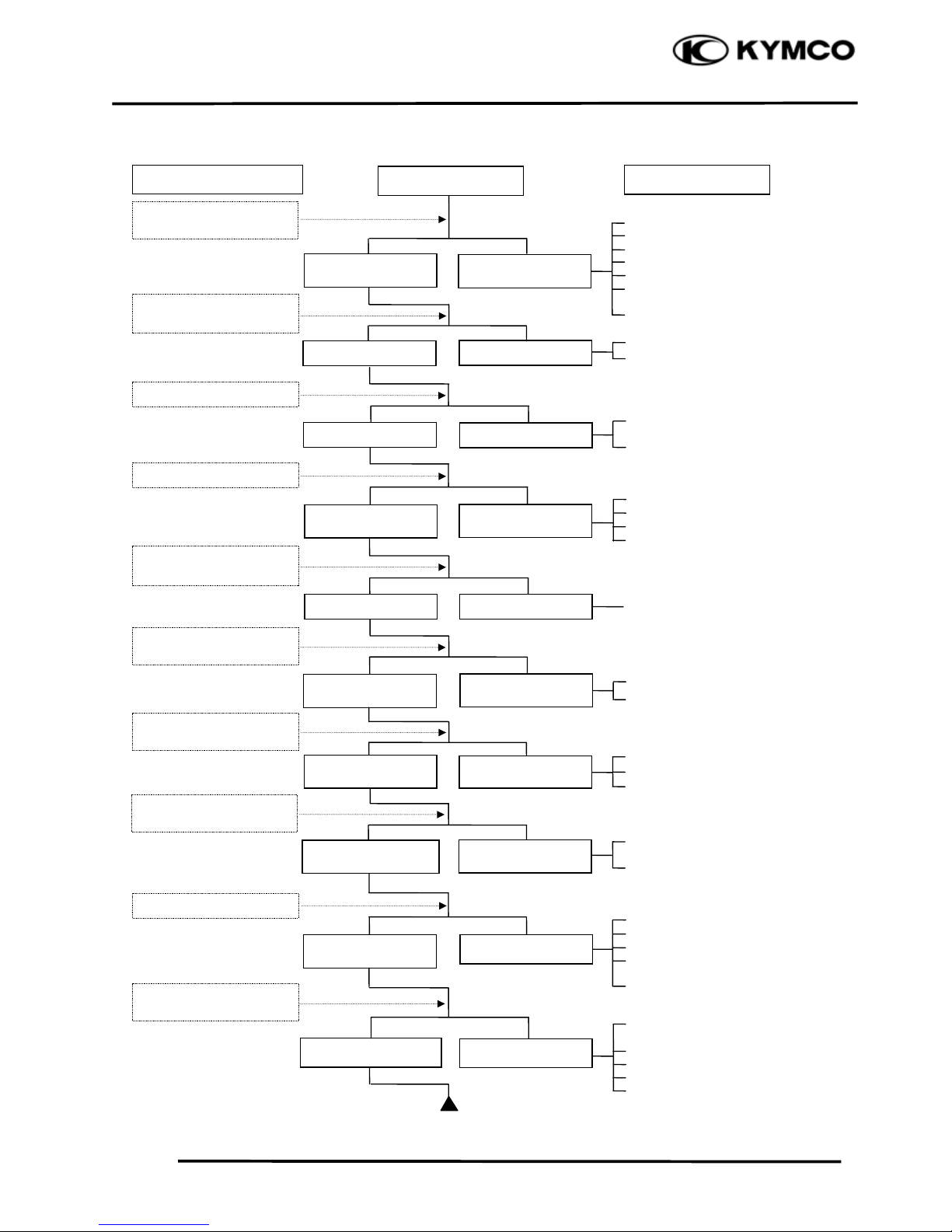
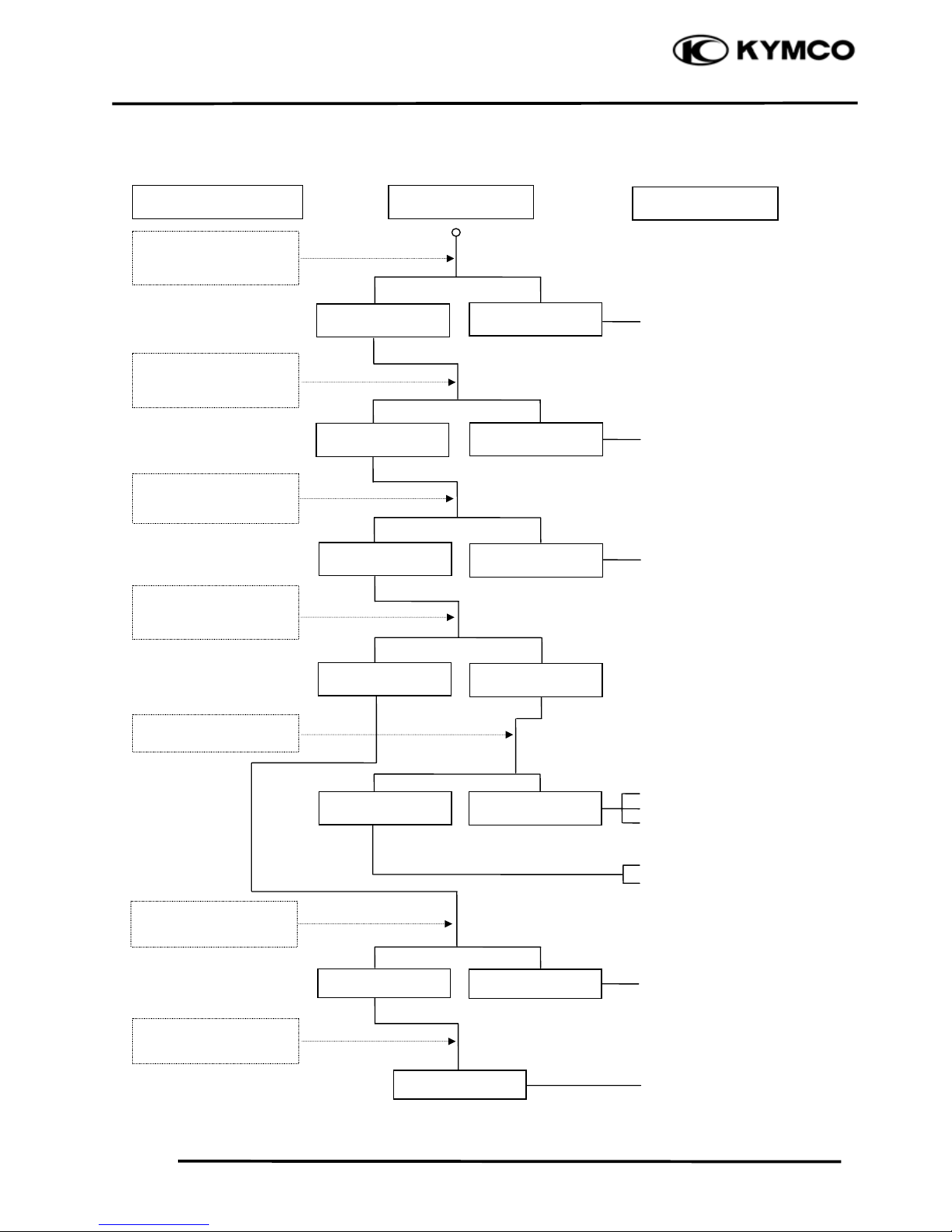
ENGINE LACKS POWER
Clogged air cleaner
Poor quality fuel (Restricted)
Clogged fuel tank cap breather hole
Clogged exhaust muffler
Faulty auto bystarter
Split carburetor vacuum piston
diaphragm
Faulty auto fuel valve
Faulty CDI unit
Faulty pulser coil
Improper valve clearance
adjustment
Worn valve seat (valve stem too
protruding
Improper valve and seat contact
Worn cylinder and piston rings
Leaking cylinder head gasket
Improper valve timing
Clogged carburetor jets
Fouled spark plug
Incorrect heat range plug
Oil level too high
Oil level too low
Oil not changed
Clogged oil pipe
Faulty oil pump
Worn cylinder and piston rings
Mixture too lean
Poor quality fuel
Excessive carbon buildup in
combustion chamber
Ignition timing too early
Excessive carbon build-up in
combustion chamber
Poor quality fuel
Clutch slipping
Mixture too lean
Ignition timing too early
Start engine and accelerate
lightly for observation
Inspection/Adjustment
Symptom
Probable Cause
Engine speed
Correct timin
g
Engine speed does no
t
increase sufficientl
y
Incorrect timin
g
Check ignition timing
using a timing light
Test cylinder compression
Check carburetor fo
r
clogging
Rapidly accelerate or run
at hi
g
h speed
Remove spark plug and
inspec
t
Check if engine overheats
Check valve clearance
Correc
t
Incorrec
t
N
ormal
com
p
ression
Abnormal
compression
Remove oil dipstick and
check oil level and condition
Remove cylinder head oil
pip
e bolt and inspec
t
Engine overheats
Engine does no
t
overheats
Plug not fouled o
r
discolored
Plug fouled o
r
discolored
Correct and no
t
contaminated
Incorrect o
r
contaminated
Valve train lubricated
prop
erl
y
Valve train no
t
lubricated properl
y
Engine does not knock
Engine knocks
Not clogged
Clogged
Page 26
1. GENERAL INFORMATION
1-23
AGILITY 50
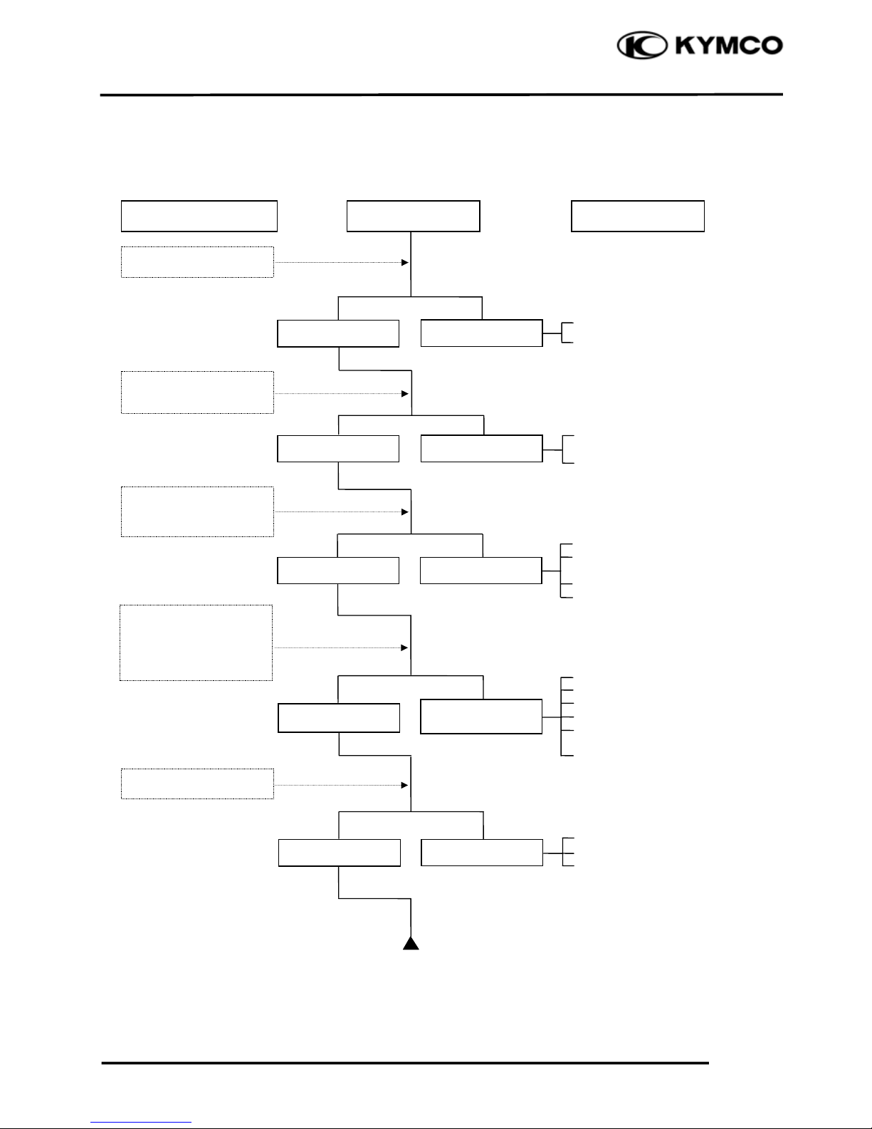
POOR PERFORMANCE (ESPECIALLY AT IDLE AND LOW SPEEDS)
Faulty CDI unit
Faulty pulser coil
Mixture too rich (turn screw
out)
Mixture too lean (turn screw in)
Deteriorated O-ring
Carburetor not securely
tightened
Damaged insulator rubber
Broken vacuum tube
Faulty or fouled spark plug
Faulty CDI unit
Faulty A.C. generator
Faulty ignition coil
Broken or shorted spark plug
wire
Faulty ignition switch
Faulty air cut-off valve
Damaged vacuum tube
Clogged or damaged air vent
hole
Remove spark plug and
install it into spark plug
cap to test spark by
connecting it to engine
g
round
Inspection/Adjustment Symptom Probable Cause
Check ignition timing
Check air cut-off valve
Check carburetor gaske
t
for air leaks
Check carburetor pilo
t
screw adjustment
Correct timing
Incorrect timing
Correctly adjusted
No air leak
Air leaks
Good spark
Weak or inter-
mittent spark
Good
Faulty
Incorrectly adjusted
Page 27
1. GENERAL INFORMATION
1-24
AGILITY 50
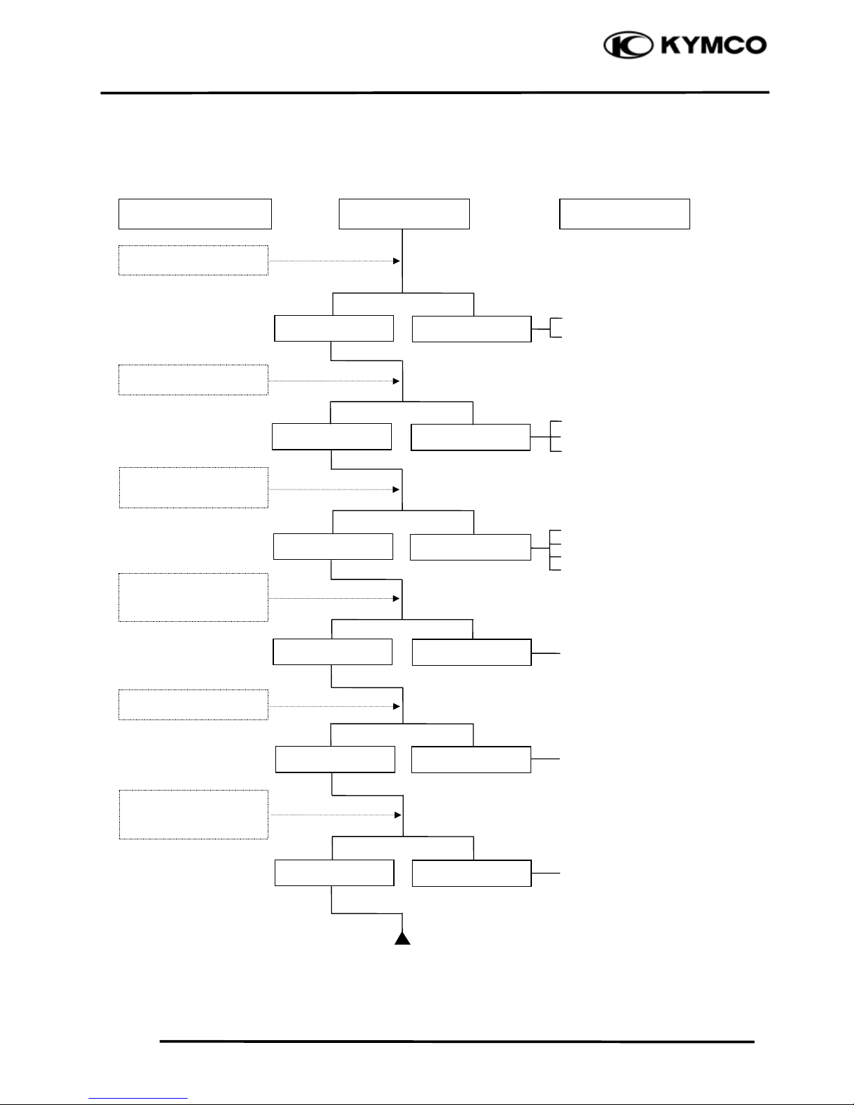
POOR PERFORMANCE (AT HIGH SPEED)
Faulty CDI unit
Faulty pulser coil
Improperly adjusted valve clearance
Worn camshaft
Worn valve seat
Empty fuel tank
Clogged fuel tube or filter
Faulty charcoal canister
Faulty auto fuel valve
Clean and unclog
Cam timing gear aligning marks
not aligned
Faulty spring
Inspection/Adjustment Symptom Probable Cause
Check ignition timing
Check carburetor jets
for clogging
Check fuel pump fo
r
fuel supply
Correct timing
Incorrect timing
Check valve spring
tension
Check valve clearance
Fuel flows freely
Fuel flow restricted
Correc
t
Incorrec
t
Not clogged
Clogged
Correctly adjusted
Incorrectly adjusted
Not weakened
Weak spring
Check valve timing
Page 28
1. GENERAL INFORMATION
1-25
AGILITY 50
POOR CHARGING (BATTERY OVER DISCHARGING OR OVERCHARGING)
Undercharging
Dead battery
Faulty battery
Faulty A.C. generator coil
Broken yellow wire
Loose connector
Broken red wire
Faulty regulator/rectifier
Poorly connected coupler
Faulty A.C. generator
Overcharging
Broken green wire
Poorly connected coupler
Faulty regulator/rectifier
Start engine and tes
t
limit voltage between
b
attery terminals
Connect battery (+) wire
to regulator/rectifier
coupler red wire and
battery (-) wire to engine
g
round and test voltage
Inspection/Adjustment
Inspection/Adjustment
Symptom
Symptom
Probable Cause
Probable Cause
Normal voltage
B
attery has voltage
with ignition
switch “ON”
Normal
Voltage does no
t
B
attery has no
voltage with ignition
switc
h
“ON”
Resistance too high
Normal voltage
No voltage
Measure resistance
between AC generator
coil terminals
Normal
Abnormal
Check regulator/rectifier
coupler for loose
connection
Normal
Abnormal
Connect battery (+) wire
to regulator/rectifier
coupler green wire and
battery (-) wire to engine
g
round and test voltage
Check regulator/rectifier
coupler for loose
connection
Page 29
1. GENERAL INFORMATION
1-26
AGILITY 50
NO SPARK AT SPARK PLUG
Faulty old spark plug
Loose spark plug cap
Poorly connected coupler
Faulty ignition switch
Faulty pulser coil
Faulty ignition coil
Broken wire harness
Poorly connected coupler
Faulty CDI unit
Faulty ignition coil
Replace with a new
spark plug and inspect
a
g
ain
Check CDI unit coupler
for looseness
Inspection/Adjustment Symptom
Probable Cause
Normal
Abnormal
Normal
Abnormal
Normal
Abnormal
Abnormal
Measure resistance
between CDI unit
cou
p
ler wire terminals
Check related parts
Check ignition coil with
a CDI unit tester
Weak or no spark
Not loose
Good spark
Loose
Good
Good
Check spark plug cap
and high-tension wire
for looseness
Check CDI unit with a
CDI unit tester
Page 30
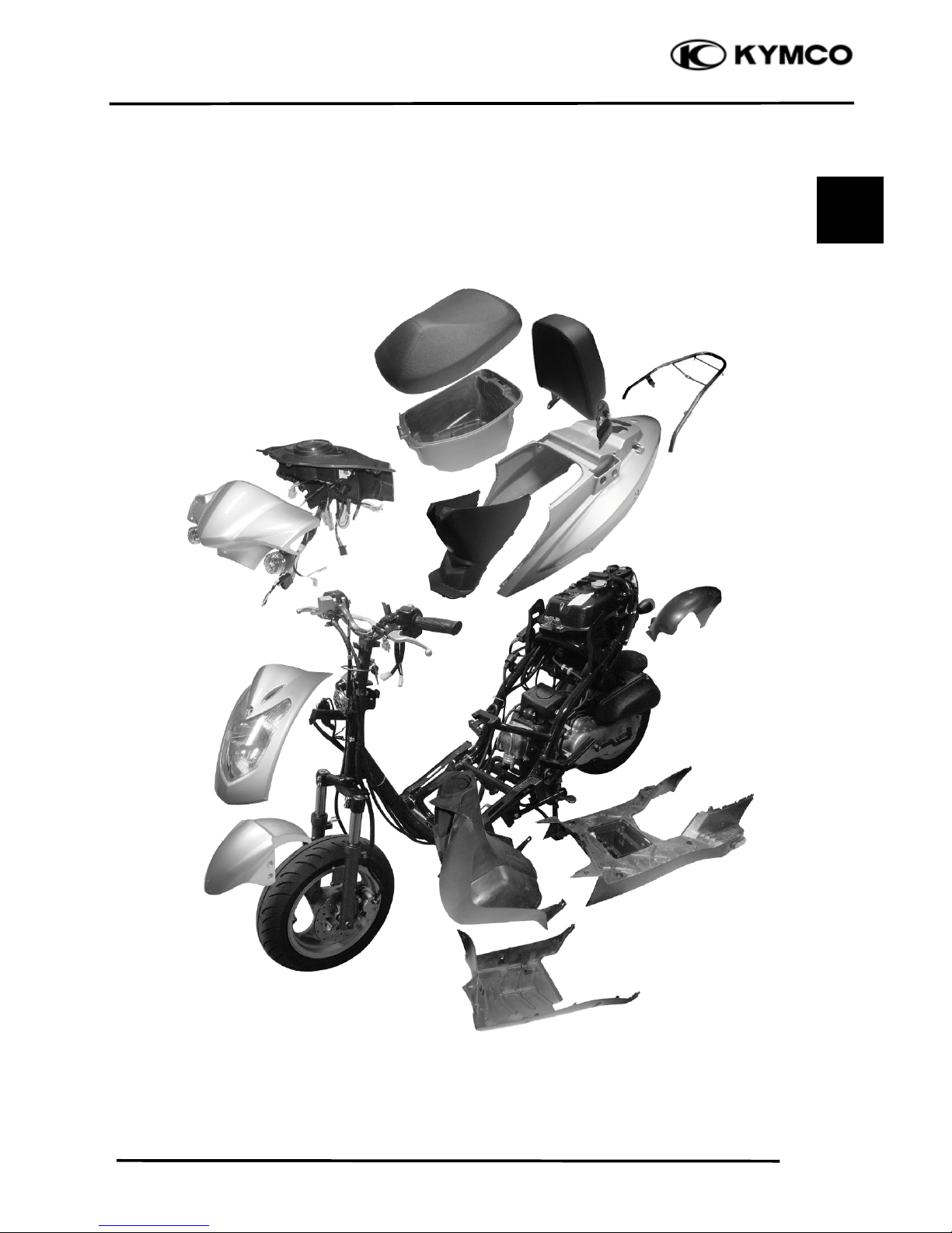
2. FRAME COVERS/EXHAUST MUFFLER
2-0
AGILITY 50
2 SCHEMATIC DRAWING
2
Page 31

2. FRAME COVERS/EXHAUST MUFFLER
2-1
AGILITY 50
SERVICE INFORMATION
GENERAL INSTRUCTIONS
xWhen removing frame covers, use special care not to pull them by force because the cover joint
claws may be damaged.
Items Related for Removal
xHandlebar front cover Handlebar rear cover
Headlight wire connector
xHandlebar rear cover Speedometer cable and instrument light
wire connectors, etc.
xFrame body cover Met-in box, rear grip, rear turn signal
lights, floor board
xFloor board Frame body cover
Battery and wire connectors
xFront tool box Front cover, floor board
TORQUE VALUES
Exhaust muffler joint lock nut 1.0~1.4kgf-m
Exhaust muffler lock bolt 3.0~3.6kgf-m
SERVICE INFORMATION...................... 2-1 EXHAUST MUFFLER REMOVAL .........2-5
FRAME COVERS ..................................... 2-2
Page 32

2. FRAME COVERS/EXHAUST MUFFLER
2-2
AGILITY 50
FRAME COVERS
FRONT COVER REMOVAL
Remove the screw on the front of the front
cover.
Remove the six screws on the back of the
front cover.
Remove the front cover.
The installation sequence is the reverse of
removal.
HANDLEBAR FRONT/REAR COVER
REMOVAL
HANDLEBAR FRONT COVER REMOVAL
Remove the handlebar front cover screw.
Remove the two screws attaching the
handlebar front cover.
Disconnect the headlight wire connector and
remove the handlebar front cover.
HANDLEBAR REAR COVER REMOVAL
Disconnect the speedometer cable, right and
left handlebar switch couplers, and the stop
switch wire connectors.
Remove the bolt attaching the handlebar rear
cover.
Remove two screws inside the handlebar rear
cover and remove the handlebar rear cover.
The installation sequence is the reverse of
removal.
Bol
t
Screw
Handlebar Front Cove
r
Screw
Front Cove
r
Screws
Handlebar Rear Cove
r
Handlebar Front Cove
r
Screws
Page 33

2. FRAME COVERS/EXHAUST MUFFLER
2-3
AGILITY 50
MET-IN BOX REMOVAL
Open the seat and remove the two nuts and
three bolt attaching the met-in box.
Remove the met-in box .
FRAME BODY COVER REMOVAL
Remove the center cover.
Remove the three bolts attaching the rear
carrier.
Remove the rear carrier.
Remove the four bolts on the rear seat.
Remove the rear seat
Remove the six screws on the rear part of the
frame body cover.
Remove the two screws on the front of the
frame body cover.
Bol
t
Rear Carrie
r
Screws
Bolts
Center Cove
r
Bolts
Screws
Bolts
Page 34

2. FRAME COVERS/EXHAUST MUFFLER
2-4
AGILITY 50
Discornnect the seat lock wire.
Remove the frame body cover.
The installation sequence is the reverse of
remove
Remove the three bolts attaching each of the
right and left side covers.
Remove the right and left side covers.
FLOOR BOARD REMOVAL
Remove the rear carrier and rear seat. (Ö2-3)
Remove the met-in box. (Ö2-3)
Remove the frame body cover. (Ö2-4)
Remove the eight bolts attaching the floor
board.
Remove the floor board.
BOTTOM PROTECTOR COVER
REMOVAL
Remove the sixbolts on the bottom protector
cover.
Remove the bottom protector cover.
Bolts
Frame Body
Bottom Protector Cove
r
Bolts
Floor Board.
Seat Lock Wire
During removal, do not pull the joint
claws forcedly to avoid damage.
When installing, be sure to connect the
seat lock wire.
*
Page 35

2. FRAME COVERS/EXHAUST MUFFLER
2-5
AGILITY 50
LEG SHIELD REMOVAL
Remove the bolt leg shield.
Remove the ignition switch decorative ring
Remove the leg shield.
F RONT FENDER REMOVAL
Remove the two bolts attaching the front
fender bracket.
Remove the front fender.
EXHAUST MUFFLER REMOVAL
Remove the two exhaust muffler joint lock
nuts.
Remove the two exhaust muffler lock bolts.
Remove the exhaust muffler.
Remove the exhaust muffler joint packing
collar.
When installing, first install the exhaust
muffler packing collar and then install the
exhaust muffler.
First install and tighten the exhaust muffler
joint lock nuts. Then, install and tighten the
exhaust muffler lock bolts.
Torques:
Exhaust muffler lock bolt: 3.0~3.6kgf-m
Exhaust muffler joint lock nut: 1.0~1.4kgf-m
Bolts
Lock Nu
t
Front Fende
r
Bolts
Leg shield
Be sure to install a new exhaust muffle
r
packing collar.
*
Bol
t
Decorative Ring
Page 36

3. INSPECTION/ADJUSTMENT
3-0
AGILITY 50
3
SERVICE INFORMATION
GENERAL
l WARNING
xBefore running the engine, make sure that the working area is well-ventilated. Never run the
engine in a closed area. The exhaust contains poisonous carbon monoxide gas which may
cause death to people.
xGasoline is extremely flammable and is explosive under some conditions. The working area
must be well-ventilated and do not smoke or allow flames or sparks near the working area or
fuel storage area.
SPECIFICATIONS
ENGINE
Throttle grip free play : 2Д6mm
Spark plug gap : 0.6Д0.7mm
Spark plug : NGK C7HSA
Valve clearance : IN: 0.04mm
:EX: 0.04mm
Idle speed : 1900 Ô100rpm
Engine oil capacity:
At disassembly : 0.85 liter
At change : 0.7 liter
Gear oil capacity :
At disassembly : 0.11 liter
At change : 0.10 liter
3
SERVICE INFORMATION....................3-0 FINAL REDUCTION GEAR OIL.......3- 7
MAINTENANCE SCHEDULE...............3-2 DRIVE BELT.........................................3- 7
FUEL FILTER..........................................3-3 BRAKE SHOE.......................................3- 8
THROTTLE OPERATION.....................3-3 BRAKE ADJUSTING NUT..................3- 8
AIR CLEANER ........................................3-4 HEADLIGHT AIM ...............................3- 9
SPARK PLUG ..........................................3-4 CLUTCH SHOE WEAR.......................3- 9
VALVE CLEARANCE............................3-5 SUSPENSION ........................................3- 9
CARBURETOR IDLE SPEED...............3-5 NUTS/BOLTS/FASTENERS................3-10
IGNITION TIMING................................3-6 WHEELS/TIRES...................................3-10
CYLINDER COMPRESSION................3-6 STEERING HANDLEBAR..................3-11
Page 37

3. INSPECTION/ADJUSTMENT
3-1
AGILITY 50
Cylinder compression : 16 kg/cm
2
Ignition timing: BTDC 28Ę/4000rpm
CHASSIS
Front brake free play: 10Д20mm
Rear brake free play : 10Д20mm
TIRE PRESSURE
1 Rider 2 Riders
Front 1.5kg/cm
2
1.75kg/cm
2
Rear 2.0kg/cm
2
2.25kg/cm
2
TIRE SIZE:
Front : 120/70-12
Rear : 130/70-12
TORQUE VALUES
Front axle nut 5.0Д7.0kgf-m
Rear axle nut 11Д13kgf-m
Page 38

3. INSPECTION/ADJUSTMENT
3-2
AGILITY 50
MAINTENANCE SCHEDULE
Perform the periodic maintenance at each scheduled maintenance period.
I: Inspect, and Clean, Adjust, Lubricate or Replace if necessary.
A: Adjust C: Clean R: Replace T : Tighten
Regular Service Mileage (km)
Frequenc
y
Item
comes
first
Ö
Ø
1000
Engine oil
R
New
Motorcycle
300k
m
RRR
R
RR
Engine oil filter
screen
CC
Fuel filter screen R
Gear oil Note 3
R
New
motorcycle
300k
m
R
R
Valve clearance A A A A
Carburetor I I C
Air Cleaner Note 2,3 Replace at every2000km
Spark plug Clean at every 3000km and replace if necessary
Brake system I IIIIIIIII I I
Drive belt I
Suspension I I I
Nut, bolt, fastener I
Tire I I I
Steering head bearing I I I
xIn the interest of safety, we recommend these items should be serviced only by an authorized
KYMCO motorcycle dealer.
Note: 1. For higher odometer readings, repeat at the frequency interval established here.
2. Service more frequently when riding in dusty or rainy areas.
3. Service more frequently when riding in rain or at full throttle.
Whicheve
r
Page 39

3. INSPECTION/ADJUSTMENT
3-3
AGILITY 50
FUEL FILTER
Remove the met-in box. (Ö2-3)
Check the fuel lines and replace any parts
which show signs of deterioration, damage or
leakage.
THROTTLE OPERATION
Check the throttle grip for smooth movement.
Measure the throttle grip free play.
Free Play: 2Д6mm
Major adjustment of the throttle grip free play
is made at the carburetor side.
Adjust by loosening the lock nut and turning
the adjusting nut.
Minor adjustment is made with the adjusting
nut at the throttle grip side.
Slide the rubber cover out and adjust by
loosening the lock nut and turning the
adjusting nut.
Lock Nu
t
Adjusting Nu
t
Fuel Filte
r
Do not smoke or allow flames or sparks
in your working area.
*
Fuel Line
Lock Nu
t
Adjusting Nu
t
2Д6m
m
Page 40

3. INSPECTION/ADJUSTMENT
3-4
FILLY LX 50
AIR CLEANER
AIR CLEANER REPLACEMENT
Remove the air cleaner case cover screws and
the cover by removing the seven screws.
Remove the air cleaner element by removing
the four screws.
Check the element and replace it if it is
excessively dirty or damaged.
CHANGE INTERVAL
More frequent replacement is required when
riding in unusually dusty or rainy areas.
SPARK PLUG
Remove the spark plug.
Check the spark plug for wear and fouling
deposits.
Clean any fouling deposits with a spark plug
cleaner or a wire brush.
Specified Spark Plug:
CHAMPION-P-RZ9HC
Measure the spark plug gap.
Spark Plug Gap: 0.6Д0.7mm
Cracks
Damage
Gap, Wear, and
Fouling Deposits
xThe air cleaner element has a viscous
type paper element. Do not clean it
with any fluid.
xBe sure to install the air cleaner
element and cover securely.
*
When installing, first screw in the spar
k
plug by hand and then tighten it with a
spark plug wrench.
*
Screws
Air Cleaner Case Cove
r
Air Cleaner Elemen
t
Washe
r
Deformation
Page 41

3. INSPECTION/ADJUSTMENT
3-5
AGILITY 50
VALVE CLEARANCE
Remove the frame cover. (Ö2-3)
Remove the six bolts on the cylinder head
cover.
Remove the cylinder head cover. (Ö7-3)
Remove the cylinder head cover..
Turn the flywheel counterclockwise so that
the “T” mark on the flywheel aligns with the
index mark on the crankcase to bring the
round hole on the camshaft gear facing up to
the top dead center on the compression
stroke.
Inspect and adjust the valve clearance.
Valve Clearance: IN : 0.04mm
EX: 0.04mm
Loosen the lock nut and adjust by turning the
adjusting nut
Tappet Adjuster
CARBURETOR IDLE SPEED
Remove the inspection cover.
Warm up the engine before this operation.
Start the engine and connect a tachometer.
Turn the throttle stop screw to obtain the
specified idle speed.
Idle Speed: 1900Ô100rpm
When the engine misses or run erratic, adjust
the pilot screw.
Throttle Stop Screw
Inspect and adjust valve clearance while
the engine is cold (below 35Ċ).
*
Special
xCheck the valve clearance again afte
r
the lock nut is tightened.
*
xThe engine must be warm for accurate
idle speed inspection and adjustment.
*
Cylinder Head Cove
r
Bolts
Round Hole
Tappet Adjuste
r
Feeler Gauge
Page 42

3. INSPECTION/ADJUSTMENT
3-6
FILLY LX 50
IGNITION TIMING
Remove the right of the fan cover.
Check the ignition timing with a timing light.
When the engine is running at idle speed, the
ignition timing is correct if the “F” mark on
the flywheel aligns with the index mark on
the crankcase.
Also use a timing light to check the advance.
Raise the engine speed to 4,000rpm and the
index mark on the crankcase cover should be
aligned with the advance mark on the
flywheel.
CYLINDER COMPRESSION
Warm up the engine before compression test.
Remove the met-in box and center cover.
(Ö2-3)
Remove the spark plug.
Insert a compression gauge.
Open the throttle valve fully and push the
starter button to test the compression.
Compression: 16kg/cm2rpm
If the compression is low, check for the
following:
ΘLeaky valves
ΘValve clearance to small
ΘLeaking cylinder head gasket
ΘWorn piston rings
ΘWorn piston/cylinder
If the compression is high, it indicates that
carbon deposits have accumulated on the
combustion chamber and the piston head.
Compression Gauge
Timing Ligh
t
The CDI unit is not adjustable. If the
ignition timing is incorrect, check the
ignition system. (Ö15-5)
*
Timing Hole Cap
Advance Mark
“F” Mark
Page 43

3. INSPECTION/ADJUSTMENT
3-7
AGILITY 50
FINAL REDUCTION GEAR OIL
OIL LEVEL CHECK
Stop the engine and remove the oil check bolt.
The oil level shall be at the oil check bolt
hole.
If the oil level is low, add the recommended
oil to the proper level.
Recommended Oil: SAE90#
Install the oil check bolt.
OIL CHANGE
Remove the oil check bolt.
Remove the oil drain bolt and drain the oil
thoroughly.
Install the oil drain bolt.
Torque: 0.8~1.2kgf-m
Fill with the recommended oil.
Oil Capacity: At disassembly : 0.11 liter
At change : 0.10 liter
Reinstall the oil check bolt and check for oil
leaks.
Torque:0.8~1.2kgf-m
DRIVE BELT
Remove the left crankcase cover. (Ö9-2)
Inspect the drive belt for cracks or excessive
wear.
Replace the drive belt with a new one if
necessary and in accordance with the
Maintenance Schedule.
Drive Bel
t
Oil Check Bolt/Sealing Washe
r
Place the motorcycle on its main stan
d
on level ground for oil level check.
*
Make sure that the sealing washer is in
good condition.
*
Oil Check Bolt Hole
Oil Drain Bolt/ Sealing Washe
r
Make sure that the sealing washer is in
good condition.
*
Page 44

3. INSPECTION/ADJUSTMENT
3-8
FILLY LX 50
BRAKE SHOE
Replace the brake shoes if the arrow on the
wear indicator plate aligns with the punch
mark on the brake panel when the brake is
fully applied.
Refer to page 12-7 and 13-3 for brake shoe
replacement.
REAR BRAKE
Measure the rear brake lever free play.
Free Play: 10Д20mm
BRAKE ADJUSTING NUT
If the free play do not fall within the limit,
adjust by turning the adjusting nut.
BRAKE FLUID
Turn the steering handlebar upright and check
if the rear brake fluid level should be between
the upper and lower level lines.
Specified Brake Fluid: DOT-4f
Arrows
Adjusting Nu
t
Punch Mark
Upper Line
Lower Line
Page 45

3. INSPECTION/ADJUSTMENT
3-9
AGILITY 50
If the free play do not fall within the limit,
adjust by turning the adjusting nut.
HEADLIGHT AIM
Turn the ignition switch ON and start the
engine.
Turn on the headlight switch.
Adjust the headlight aim by turning the
headlight aim adjusting screw.
CLUTCH SHOE WEAR
Start the engine and check the clutch
operation by increasing the engine speed
gradually.
If the motorcycle tends to creep, or the engine
stalls, check the clutch shoes for wear and
replace if necessary. (Ö9-11)
SUSPENSION
FRONT
Fully apply the front brake lever and check
the action of the front shock absorbers by
compressing them several times.
Check the entire shock absorber assembly for
oil leaks, looseness or damage.
Adjusting Screw
Adjusting Nu
t
clutc
h
Front Cove
r
Page 46

3. INSPECTION/ADJUSTMENT
3-10
FILLY LX 50
REAR
Check the action of the rear shock absorber
by compressing it several times.
Check the entire shock absorber assembly for
oil leaks, looseness or damage.
Jack the rear wheel off the ground and move
the rear wheel sideways with force to see if
the engine hanger bushings are worn.
NUTS/BOLTS/FASTENERS
Check all important chassis nuts and bolts for
looseness.
Tighten them to their specified torque values
if any looseness is found. (Ö1-11)
WHEELS/TIRES
Check the tires for cuts, imbedded nails or
other damages.
Check the tire pressure.
TIRE PRESSURE
1 Rider 2 Riders
Front 1.5kg/cm
2
1.75kg/cm
2
Rear 2.00kg/cm
2
2.25kg/cm
2
TIRE SIZE
Front: 120/70-12
Rear : 130/70-12
Check the front axle nut for looseness.
Check the rear axle nut for looseness.
If the axle nuts are loose, tighten them to the
specified torques.
Torques: Front : 5.0Д7.0kgf-m
Rear : 11Д13kgf-m
Tire pressure should be checked when
tires are cold.
*
Front Axle Nu
t
Page 47

3. INSPECTION/ADJUSTMENT
3-11
AGILITY 50
STEERING HANDLEBAR
Check that the control cables do not interfere
with handlebar rotation.
Raise the front wheel off the ground and
check that the steering handlebar rotates
freely.
If the handlebar moves unevenly, binds, or
has vertical movement, adjust the steering
head bearing.
Page 48

4. LUBRICATION SYSTEM
4-0
AGILITY 50
Oil PumpOil Filter Screen
Crankshaft
4 LUBRICATION SYSTEM
4
Rocker Arm Shaft
Page 49

4. LUBRICATION SYSTEM
4-1
AGILITY 50
SERVICE INFORMATION
GENERAL INSTRUCTIONS
xThe maintenance of lubrication system can be performed with the engine installed in the frame.
xUse care when removing and installing the oil pump not to allow dust and foreign matters to
enter the engine and oil line.
xDo not attempt to disassemble the oil pump. The oil pump must be replaced as a set when it
reaches its service limit.
xAfter the oil pump is installed, check each part for oil leaks.
SPECIFICATIONS
Item Standard (mm) Service Limit (mm)
Inner rotor-to-outer rotor clearance 0.12
Oil pump Outer rotor-to-pump body clearance 0.12
Rotor end-to-pump body clearance 0.05Д0.10 0.2
TROUBLESHOOTING
Oil level too low Poor lubrication pressure
xNatural oil consumption x Oil level too low
xOil leaks x Clogged oil filter or oil passages
xWorn or poorly installed piston rings x Not use the specified oil
xWorn valve guide or seal
SERVICE INFORMATION.......................4-1 ENGINE OIL/OIL FILTER ......................4-2
TROUBLESHOOTING .............................4-1 OIL PUMP................................................. 4-3
Page 50

4. LUBRICATION SYSTEM
4-2
AGILITY 50
ENGINE OIL/OIL FILTER
OIL LEVEL
Remove the oil dipstick and check the oil
level with the oil dipstick.
If the level is near the lower level, fill to the
upper level with the specified engine oil.
OIL CHANGE
Remove the drain bolt to drain the engine oil
thoroughly.
Remove the oil filter screen cap and clean the
oil filter screen with compressed air.
Check the filter screen O-ring for damage and
replace if necessary.
Install the oil filter screen, spring and filter
screen cap.
Torque: 1.0~2.0kgf-m
Fill the crankcase with the specified engine
oil to the proper level.
Oil Capacity: At disassembly : 0.85 liter
At change : 0.70 liter
Check for oil leaks and then start the engine
and let it idle for few minutes.
Recheck the oil level.
Oil Dipstick
O-ring
Oil Filter Screen Cap
xPlace the motorcycle upright on level
ground for engine oil level check.
xRun the engine for 2Д3 minutes and
check the oil level after the engine is
stopped for 2Д3 minutes.
*
The engine oil will drain more easily
while the engine is warm.
*
Page 51

4. LUBRICATION SYSTEM
4-3
AGILITY 50
Bol
t
Right Crankcase Cove
r
Oil Pump Drive Gear
Circlip
Oil Pump Gear
Oil Pump
Bolts
O-rings
OIL PUMP
REMOVAL
Remove the A.C. generator flywheel. (Ö14-7)
Remove the A.C. generator stator and pulsar
coil. (Ö14-6)
Remove the eight right crankcase cover bolts
and the right crankcase cover.
Remove the gasket and dowel pins.
Remove the oil pump drive gear circlip.
Remove the oil pump gear.
Remove the oil pump mounting bolts.
Remove the oil pump.
Remove the two O-rings.
Inspect the two O-rings for damage or
deterioration.
Page 52

4. LUBRICATION SYSTEM
4-4
AGILITY 50
Screws
Outer Rotor
Oil Pump Boby
Outer Rotor
Inner Rotor
DISASSEMBLY
Remove the three oil pump boby screws.
Disassembly the oil pump.
INSPECTION
Measure the pump boby-to-outer rotor
clearance.
Service Limit: 0.12mm
Measure the inner rotor-to-outer rotor
clearance.
Service Limit: 0.12mm
Measure the rotor end-to- pump boby
clearance.
Service Limit: 0.2mm
Oil Pump Boby
Page 53

4. LUBRICATION SYSTEM
4-5
AGILITY 50
Pump Cove
r
Screws
Inner Rotor
O-rings
Bolts
Outer Rotor
Pum
p
Shaf
t
Oil pump
ASSEMBLY
Install the outer rotor, inner rotor and pump
shaft into the pump boby.
Install the pump cover and tighten the screws
to secure the pump cover.
INSTALLATION
First install the two O-rings onto the oil pump
base.
Install the oil pump into the crankcase.
After the oil pump is installed, tighten the
three mounting bolts.
Install the pump shaft by aligning the flat
on the shaft with the flat in the inner
rotor.
*
Fill the oil pump with engine oil before
installation.
*
Page 54

4. LUBRICATION SYSTEM
4-6
AGILITY 50
Bolts
Right Crankcase Cove
r
Pump Driven Gear
Circlip
Install the pump driven gear and secure it
with the circlip.
Torque: 0.8Д1.2kg-m
Install the right crankcase cover and tighten
the eight bolts.
Torque: 0.8~1.2kgf-m
Diagonally tighten the bolts in 2Д3
times.
*
Page 55

5. FUEL SYSTEM
5-0
AGILITY 50
5
5
Page 56

5. FUEL SYSTEM
5-1
AGILITY 50
Fuse
12V Battery
Regulato
r
/Rectifier
L/Y
W
Auto Bystarte
r
Ignition Switch
CDI Unit
B
G
Y
Y
Lighting
System
Resistor
5
:
5W
G/B
.
Page 57

5. FUEL SYSTEM
5-2
AGILITY 50
SERVICE INFORMATION
GENERAL INSTRUCTIONS
xWhen disassembling the carburetor, be sure to service the vacuum piston and float chamber.
xDo not bend or twist control cables. Damaged control cables will not operate smoothly.
xWhen disassembling fuel system parts, note the locations of O-rings. Replace them with new
ones during assembly.
xBefore float chamber disassembly, loosen the drain screw to drain the residual gasoline into a
clean container.
xAfter the carburetor is removed, plug the intake manifold side with a clean shop towel to prevent
foreign matters from entering.
xRemove the vacuum diaphragm before cleaning the carburetor air and fuel passages with
compressed air to avoid damaging the vacuum diaphragm.
xWhen the motorcycle is not used for over one month, drain the residual gasoline from the float
chamber to avoid erratic idling and clogged slow jet due to deteriorated fuel.
SPECIFICATIONS
Item
Standard
Venturi dia. (mm) 20
Type CVK
Float level (mm) 17
Main jet Commonly: #82 Speed limits vehicle: #80
Slow jet #35
Idle speed 2000rpm±100
Throttle grip free play 2Д6mm
Pilot screw opening 2r
1
/2
Gasoline is very dangerous. When working with gasoline, keep sparks and flames away
from the working area.
Gasoline is extremely flammable and is explosive under certain conditions. Be sure to
work in a well-ventilated area.
SERVICE INFORMATION.......................5-2 ACCELERATING PUMP.......................5-10
TROUBLESHOOTING..............................5-3 CARBURETOR INSTALLATION.........5-11
CARBURETOR REMOVAL.....................5-4 PILOT SCREW ADJUSTMENT ............5-12
AUTO BYSTARTER.................................5-4 FUEL TANK............................................5-13
AIR CUT-OFF VALVE .............................5-6 FUEL UNIT .............................................5-14
VACUUM CHAMBER..............................5-6 AIR CLEANER .......................................5-14
FLOAT CHAMBER...................................5-8
Page 58

5. FUEL SYSTEM
5-3
AGILITY 50
TROUBLESHOOTING
Engine is hard to start Misfiring during acceleration
xNo spark at plug (ÖSection 15) x Faulty ignition system
xCompression too low x Lean mixture
xNo fuel to carburetor x Faulty accelerating pump
Clogged fuel filter Engine idles roughly, stalls or runs poorly
Restricted fuel line x Clogged fuel system
Faulty float valve x Ignition malfunction
Incorrectly adjusted float level x Rich or lean mixture
xEngine flooded with fuel x Contaminated fuel
Clogged air cleaner x Intake air leak
Fuel overflowing x Incorrect idle speed
xIntake air leak x Incorrectly adjusted pilot screw
xContaminated fuel x Clogged idle system or auto bystarter passages
xFaulty auto bystarter x Incorrectly adjusted float level
xClogged idle system or auto bystarter passages Lean mixture
Rich mixture x Clogged fuel jets
xFaulty auto bystarter x Faulty float valve
xFaulty float valve x Float level too low
xFloat level too high x Clogged fuel system
xClogged air jets x Intake air leak
xDirty air cleaner x Improper vacuum piston operation
xFlooded carburetor x Improper throttle operation
Backfiring at deceleration
xLean mixture in idle system
xImproper air cut-off valve operation
Page 59

5. FUEL SYSTEM
5-4
AGILITY 50
CARBURETOR REMOVAL
Remove the frame right side cover. (Ö2-4)
Disconnect the auto bystarter wire
connector.
Remove the met-in box. (Ö2-3)
Loosen the drain screw and drain the fuel
from the float chamber.
Disconnect the fuel tube and vacuum tube at
the carburetor.
Loosen the throttle cable adjusting nut and
lock nut, and disconnect the throttle cable
from the carburetor.
Loosen the carburetor intake manifold band
and air cleaner connecting tube band screws
and then remove the carburetor.
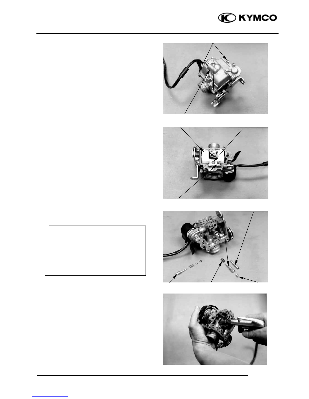
AUTO BYSTARTER
OPERATION INSPECTION
Measure the resistance between the auto
bystarter wire terminals.
Resistance:10: max. (10 minutes
minimum after stopping the engine)
If the reading is not within the limit, replace
the auto bystarter with a new one.
Adjusting Nu
t
Fuel Tube
Intake Manifold
Band
Air Cleaner Connectin
g
Tube Band
Throttle Cable
Lock Nu
t
A
uto Bystarter Wire
A
uto Bystarte
r
Page 60

5. FUEL SYSTEM
5-5
AGILITY 50
Connect a hose to the fuel enriching circuit of
the carburetor. Connect the auto bystarter
yellow wire to the positive (+) terminal of a
battery and green wire to the negative (-)
terminal. Wait 5 minutes and blow the hose
with mouth or vacuum pump. If the passage
is blocked, the auto bystarter is normal.
Disconnect the auto bystarter from the
battery. Wait 30 minutes and blow the hose
with mouth or vacuum pump. If air can be
blown into the hose, the auto bystarter is
normal.
REMOVAL
Remove the set plate screws and set plate.
Remove the auto bystarter from the
carburetor.
AUTO BYSTARTER INSPECTION
Check the auto bystarter valve and needle
for nicks, wear or damage.
If any faulty part is found, replace the auto
bystarter as a set.
INSTALLATION
Insert the auto bystarter into the carburetor
body until it bottoms.
Position the set plate into the groove in the
auto bystarter and tighten the screws.
Auto Bystarte
r
Screws
Bystarter Needle
Bystarter Valve
Auto Bystarte
r
Screws
Set Plate
Vacuum Pump
Adopte
r
Set Plate
xBe sure to install the auto bystarter an
d
set plate properly.
xInstall the set plate with its bottom face
facing down.
*
Page 61

5. FUEL SYSTEM
5-6
AGILITY 50
AIR CUT-OFF VALVE
DISASSEMBLY
Remove the two screws attaching the
throttle cable set plate and the set plate.
Remove the two screws attaching the air
cut-off valve.
Remove the spring and vacuum diaphragm.
Check the vacuum diaphragm for cracks or
damage and check each passage for
clogging.
ASSEMBLY
Install the vacuum diaphragm onto the
carburetor.
Install the spring and air cut-off valve cover.
Install the throttle cable set plate and tighten
the two screws.
VACUUM CHAMBER
DISASSEMBLY
Remove the two vacuum chamber cover
screws and the cover.
Remove the spring and vacuum diaphragm/
piston.
Spring
Spring
Throttle Cable Set Plate
Vacuum Diaphragm/Piston
Air Cut-off Valve Cove
r
Cove
r
Screws
O-rin
g
Screws
Screws
xBe sure to set the vacuum diaphrag
m
lip into the groove on the carburetor.
xWhen installing the air cut-off valve
cover, make sure that the vacuum
diaphragm is properly installed.
*
Diaphrag
m
Vacuum Chamber Cove
r
Spring
Page 62

5. FUEL SYSTEM
5-7
AGILITY 50
Remove the needle holder and jet needle.
INSPECTION
Inspect the needle for stepped wear.
Inspect the vacuum piston for wear or
damage.
Inspect the diaphragm for deterioration and
tears.
ASSEMBLY
Install the vacuum piston/diaphragm in the
carburetor body.
Install the spring and then install the
vacuum chamber cover.
Tighten the two screws.
Vacuum Chamber Cove
r
Vacuum Diaphrag
m
Jet Needle
Vacuum Diaphrag
m
Be careful not to damage the vacuu
m
diaphragm.
*
xBe careful not to damage the diaphragm.
xHold the vacuum piston while
tightening the vacuum chamber cover.
*
Page 63
5. FUEL SYSTEM
5-8
AGILITY 50
FLOAT CHAMBER
DISASSEMBLY
Remove the three float chamber screws and
the float chamber.
Loosen the float pin screw.
Remove the float pin, float and float valve.
Remove the main jet, needle jet holder,
needle jet, slow jet and pilot screw.
Clean the removed fuel jets with detergent
oil and blow them open with compressed
air.
Blow compressed air through all passages
of the carburetor body.
Pilot Screw
Float ValveFloa
t
Float Pin
Float Chambe
r
Slow Je
t
Main Je
t
N
eedle Jet Holde
r
N
eedle Je
t
Screws
xBe careful not to damage the fuel jets
and pilot screw.
xBefore removing, turn the pilot screw
in and carefully count the number of
turns until it seats lightly and then
make a note of this.
xDo not force the pilot screw against its
seat to avoid seat damage.
*
Page 64

5. FUEL SYSTEM
5-9
AGILITY 50
INSPECTION
Inspect the float valve and valve seat for
damage or clogging.
Inspect the float valve and valve seat
contact area for stepped wear or
contamination.
ASSEMBLY
Install the slow jet, needle jet, needle jet
holder, main jet and pilot screw.
Standard Opening: 2r
1
/2
turns
Install the float valve, float and float pin.
Secure the float pin with the screw.
FLOAT LEVEL INSPECTION
Measure the float level.
Float Level: 17.0mm
This installation sequence is the reverse of
removal.
Float Level Gauge
Float Valve
xCheck the operation of the float valve
and float before this inspection.
xMeasure the float level by placing the
float level gauge on the float chamber
face parallel with the main jet.
*
Float Pin
Pilot Screw
Slow Je
t
Main Je
t
N
eedle Jet Holde
r
N
eedle Je
t
Valve Sea
t
Floa
t
Screw
Worn or contaminated float valve an
d
valve seat must be replaced because it
will result in float level too high due to
incomplete airtightness.
*
Return the pilot screw to the original
position as noted during removal.
*
Page 65

5. FUEL SYSTEM
5-10
AGILITY 50
ACCELERATING PUMP
DISASSEMBLY
Remove the two accelerating pump cover
screws and accelerating pump cover.
Remove the spring and accelerating pump
diaphragm.
INSPECTION
Inspect the accelerating pump diaphragm
for cracks, damage or deterioration.
Replace if necessary.
Check each accelerating pump fuel passage
for clogging
Clean and blow them open with compressed
air.
Install the accelerating pump in the reverse
order of removal.
Compressed Ai
r
Screws
Diaphrag
m
Diaphrag
m
Compressed Ai
r
Be careful not to damage the diaphragm
during installation.
*
Page 66

5. FUEL SYSTEM
5-11
AGILITY 50
CARBURETOR INSTALLATION
Tighten the drain screw.
Install the carburetor onto the intake
manifold, aligning the tab on the carburetor
with the cutout in the intake manifold.
Tighten the intake manifold band screw.
Install the air cleaner connecting tube and
tighten the band screw.
Connect the throttle cable to the throttle
wheel on the carburetor.
Tighten the lock nut.
Connect the fuel tube and vacuum tube to
the carburetor.
Connect the auto bystarter wire connector.
Perform the following inspections and
adjustments:
-Throttle grip free play (Ö3-3)
-Carburetor idle speed (Ö3-5)
Auto Bystarter Wire Connecto
r
Fuel Tube
Connecting Tube Band
Throttle Cable
Throttle Cable
Lock Nut
Adj
usting Nut
Page 67

5. FUEL SYSTEM
5-12
AGILITY 50
PILOT SCREW ADJUSTMENT
*
ADJUSTMENT
A tachometer must be used when adjusting
the engine speed.
Turn the pilot screw clockwise until it seats
lightly and back it out to the specification
given.
Standard Opening: 2r
1
/2
turns
Warm up the engine and adjust the throttle
stop screw to obtain the specified idle
speed.
Idle Speed: 1900Ô100rpm
Turn the pilot screw in or out slowly to
obtain the highest engine speed.
Slightly accelerate several times to make
sure that the idle speed is within the
specified range.
If the engine misses or runs erratic, repeat
the above steps.
Pilot Screw
Throttle Stop Screw
xThe pilot screw is factory pre-set an
d
no adjustment is necessary. During
carburetor disassembly, note the
number of turns of the pilot screw and
use as a reference when reinstalling it.
xPlace the motorcycle on its main stand
on level ground for this operation.
*
xThe carburetor must be adjusted when
the engine is warm and the auto
bystarter is closed.
xDo not force the pilot screw against its
seat to prevent damage.
*
Page 68

5. FUEL SYSTEM
5-13
AGILITY 50
FUEL TANK REMOVE
Remove the net-in box. (Ö2-3)
Remove the frame center cover.
Remove the frame body cover. (Ö2-3)
Remove the four bolts on the fuel tank, take
the upper seat lock off.
Disconnect the fuel unit wire connector.
Remove the fuel tank.
The installation sequence is the reverse of
removal.
FUEL STRAINER REMOVAL
Remove the fuel strainer from the fuel tank.
INSPECTION
Inspect if the fuel strainer is clogged and
clean it with compressed air.
INSTALLATION
Install the fuel strainer with its arrow mark
toward the fuel pump.
Bolts
xWhen removing the fuel strainer, do
not allow flames or sparks near the
working area and drain the residual
gasoline into a container.
*
Seat Loc
k
Arrow Mar
k
Fuel Straine
r
Fuel
Tank
Fuel Unit Wite
Connector
Page 69

5. FUEL SYSTEM
5-14
AGILITY 50
FUEL UNIT
REMOVAL
Remove the related parts.
Disconnect the fuel unit wire connector.
Turn the fixed plate on the fuel unit,take the
fuel unit off.
INSTALLATION
Inspet if the fuel unit is damaged,or harden.
Assemble the fuel unit in the reverse order
of disassembly.
AIR CLEANER
Loosen the air cleaner connecting tube band
screw.
Disconnect the clinhead cover breather tube
from the air cleaner.
Remove the two bolts and air cleaner case.
Fuel Unit Wire
Align Mark
Fuel Unit
Fuel Tank
Do not bend the float arm on the fuel
unit,otherwise the figure on the fuel
meter will not correct.
*
xAlign the groove on the fuel unit with
the angle on the fuel tank.
xInspect if the fuel tank leaked after
installing and filling the gasoling.
*
b
olts
air cleane
r
Page 70

5. FUEL SYSTEM
5-15
AGILITY 50
The installation sequence is the reverse of removal.
Page 71

6. ENGINE REMOVAL/INSTALLATION
6-0
FILLY LX 50
6
6
Page 72

6. ENGINE REMOVAL/INSTALLATION
6-1
FILLY LX 50
SERVICE INFORMATION
GENERAL INSTRUCTIONS
xA floor jack or other adjustable support is required to support and maneuver the engine. Be
careful not to damage the motorcycle body, cables and wires during engine removal.
xUse shop towels to protect the motorcycle body during engine removal.
xParts requiring engine removal for servicing:
Crankcase
Crankshaft
SERVICE INFORMATION...................... 6-1 ENGINE INSTALLATION.......................6-4
ENGINE REMOVAL................................ 6-2
Page 73

6. ENGINE REMOVAL/INSTALLATION
6-2
FILLY LX 50
ENGINE REMOVAL
Disconnect the battery negative cable.
Remove the frame body cover. (Ö2-3)
Disconnect the spark plug high tension wire.
Disconnect the auto bystarter wire connector.
Disconnect the A.C. generator wire
connector.
Disconnect the starter motor cable and earth
cable from the starter motor.
Remove the fuel tube.
Remove the spark plug cap.
Disconnect the vacuum tube.
Loosen the throttle cable adjusting nut and
lock nut, and disconnect the throttle cable
from the carburetor.
Auto Bystarter Wire Connecto
r
Vacuum Tube
Spark Plug High Tension Wire
Band
N
egative Cable
S
tarter Motor Cable
Earthr Cable
Lock Nut
Adjusting Nut
Page 74

6. ENGINE REMOVAL/INSTALLATION
6-3
FILLY LX 50
Loosen the drive belt air cleaner connecting
tube band screw and remove the connecting
tube.
Remove the rear brake adjusting nut,
connector pin rear brake cable.
Remove the rear shock absorber upper mount
bolt.
Remove the engine mounting bolt and move
the motorcycle forward to separate it from the
engine.
Support the motorcycle with a floor jack.
Rear Shock Absorber Upper Mount Bol
t
connecting tube
Air Tube Band
Adjusting Nut
Engine Mounting Bol
t
Engine Hange
r
Bracket Bolt
Page 75

6. ENGINE REMOVAL/INSTALLATION
6-4
FILLY LX 50
ENGINE HANGER BRACKET
REMOVAL
Remove the return spring from the main
stand.
Remove the main stand.
Remove the engine hanger bracket bolts and
engine hanger bracket.
Inspect the engine hanger bushings and
stopper spring for wear or damage.
ENGINE HANGER BRACKET
INSTALLATION
Install the engine hanger bracket to the
chassis and tighten the bolt.
Install the main stand onto the engine and
install the return spring.
ENGINE INSTALLATION
Install the engine and tighten the engine
mounting bolt.
Torque: 4.5~5.5kgf-m
Tighten the rear shock absorber upper mount
bolt.
Torque: 4.5~5.5kgf-m
Bushing
Engine Mounting Bol
t
Return Sprin
g
Main Stand
Return Sprin
g
Main Stand
Stopper Spring
Engine Hanger Bracket Bol
t
Page 76

6. ENGINE REMOVAL/INSTALLATION
6-5
FILLY LX 50
Install the removed parts in the reverse order
of removal.
After installation, inspect and adjust the
following:
xThrottle grip free play (
Ö
3-3)
xRear brake adjustment (
Ö
3-8)
Rear Shock Absorber Upper Mount Bol
t
Route the wires and cables properly.
*
Page 77

7. CYLINDER HEAD/VALVES
7-0
AGILITY 50
7
7
Page 78
7. CYLINDER HEAD/VALVES
7-1
FILLY LX 50
SERVICE INFORMATION
GENERAL INSTRUCTIONS
xThe cylinder head can be serviced with the engine installed in the frame.
xWhen assembling, apply molybdenum disulfide grease or engine oil to the valve guide movable
parts, valve arm and camshaft sliding surfaces for initial lubrication.
xThe camshaft is lubricated by engine oil through the cylinder head engine oil passages. Clean and
unclog the oil passages before assembling the cylinder head.
xAfter disassembly, clean the removed parts and dry them with compressed air before inspection.
xAfter removal, mark and arrange the removed parts in order. When assembling, install them in
the reverse order of removal.
SPECIFICATIONS
Item
Standard (mm) Service Limit (mm)
IN 0.04
EX 0.04
Cylinder head compression 14kg/cm
2
Cylinder head warpage 0.05
IN 26.438 26.038
EX 25.807 25.407
IN 10.000-10.015 10.10
EX 10.000-10.015 10.10
Valve rocker arm shaft IN 9.972-9.987 9.91
O.D.
EX 9.972-9.987 9.91
IN 1.0 1.8
EX 1.0 1.8
IN 4.975-4.990 4.9
EX 4.955-4.970 4.9
IN 5.000-5.012 5.03
EX 5.000-5.012 5.03
Valve stem-to-guide IN 0.010-0.037 0.08
clearance
EX 0.030-0.057 0.1
Inne
r
31.1 30.1
Oute
r
34.35 33.3
SERVICE INFORMATION......................7-1 CYLINDER HEAD DISASSEMBLY.......7-7
TROUBLESHOOTING ............................7-2 CYLINDER HEAD ASSEMBLY.............7-8
CAMSHAFT REMOVAL.........................7-3 CYLINDER HEAD INSTALLATION .....7-8
CYLINDER HEAD REMOVAL..............7-5 CAMSHAFT INSTALLATION................7-9
Valve clearance (cold)
Camshaft cam height
Valve rocker arm I.D.
Valve seat width
Valve stem O.D.
Valve guide I.D.
Valve spring free
Page 79

7. CYLINDER HEAD/VALVES
7-2
AGILITY 50
TORQUE VALUES
Cylinder head nut 1.8~2.2kgf-m Apply engine oil to threads
Valve clearance adjusting nut 0.7~1.1kgf-m Apply engine oil to threads
SPECIAL TOOLS
Valve spring compressor
TROUBLESHOOTING
xThe poor cylinder head operation can be diagnosed by a compression test or by tracing engine
top-end noises.
Poor performance at idle speed White smoke from exhaust muffler
xCompression too low x Worn valve stem or valve guide
x Damaged valve stem seal
Compression too low
xIncorrect valve clearance adjustment Abnormal noise
xBurned or bend valves x Incorrect valve clearance adjustment
xIncorrect valve timing x Sticking valve or broken valve spring
xBroken valve spring x Damaged or worn camshaft
xPoor valve and seat contact x Worn cam chain guide
xLeaking cylinder head gasket x Worn camshaft and rocker arm
xWarped or cracked cylinder head
x Poorly installed spark plug
Compression too high
xExcessive carbon build-up in combustion
chamber
Page 80

7. CYLINDER HEAD/VALVES
7-3
FILLY LX 50
CAMSHAFT REMOVAL
Remove the center cover. (Ö2-3)
Remove the frame center.
Remove the four cylinder head cover bolts to
remove the cylinder head cover.
Remove the cam chain tensioner sealing bolt
and spring.
Remove the two bolts attaching the cam chain
tensioner and the tensioner.
Turn the flywheel counterclockwise so that
the “T” mark on the flywheel aligns with the
index mark on the crankcase to bring the
round hole on the camshaft gear facing up to
the top dead center on the compression
stroke.
Remove the two cylinder head bolts.
Remove the four cylinder head nuts and
washers.
Remove the camshaft holder.
Cylinder Head Cove
r
Sealing Bol
t
Round Hole
Camshaft Gea
r
Bolts
Diagonally loosen the cylinder head nuts
in 2 or 3 times.
*
Punch Marks
Washe
r
Nut
Page 81

7. CYLINDER HEAD/VALVES
7-4
AGILITY 50
Remove the camshaft holder and dowel pins.
Remove the camshaft gear from the cam
chain and remove the camshaft.
CAMSHAFT INSPECTION
Check each cam lobe for wear or damage.
Measure the cam lobe height.
Service Limits:
IN : 26.038mm replace if below
EX: 25.407mm replace if below
Check each camshaft bearing for play or
damage. Replace the camshaft assembly
with a new one if the bearings are noisy or
have excessive play.
Cam Chain Camshaft Gea
r
Camshaft Bearings
Camshaft Holde
r
Dowel Pins
Camshaf
t
Page 82

7. CYLINDER HEAD/VALVES
7-5
FILLY LX 50
CAMSHAFT HOLDER DISASSEMBLY
Take out the valve rocker arm shafts using a
5mm bolt.
Remove the valve rocker arms.
CAMSHAFT HOLDER INSPECTION
Inspect the camshaft holder, valve rocker
arms and rocker arm shafts for wear or
damage.
Measure the I.D. of each valve rocker arm.
Service Limits: IN:10.10mm replace if over
EX:10.10mm replace if over
Measure each rocker arm shaft O.D.
Service Limits: IN: 9.91mm replace if over
EX: 9.91mm replace if over
CYLINDER HEAD REMOVAL
Remove the camshaft. (Ö7-3)
Remove the carburetor. (Ö5-5)
Remove the exhaust muffler. (Ö2-5)
Remove the carburetor intake manifold.
Intake Manifold
Camshaft Holde
r
If the valve rocker arm contact surface is
worn, check each cam lobe for wear or
damage.
°
Rocker Arm Shafts
5mm Bol
t
Rocker Ar
m
Rocker Arm Shaf
t
Page 83

7. CYLINDER HEAD/VALVES
7-6
AGILITY 50
Remove the cooling fan cover. (Ö14-6)
Remove the engine cover bolts and screws.
Separate the engine cover joint claws.
Remove the cylinder head.
Remove the dowel pins and cylinder head
gasket.
Remove the cam chain guide.
Cylinder Head
Dowel Pins
Cam Chain Guide
C
y
linder Head Gaske
t
Bolts
Page 84

7. CYLINDER HEAD/VALVES
7-7
FILLY LX 50
CYLINDER HEAD DISASSEMBLY
Remove the valve spring cotters, retainers,
springs, spring seats and valve stem seals
using a valve spring compressor.
Valve Spring Compressor
Valve Spring Compressor Attachment
Remove carbon deposits from the combustion
chamber.
Clean off any gasket material from the
cylinder head mating surface.
INSPECTION
CYLINDER HEAD
Check the spark plug hole and valve areas for
cracks.
Check the cylinder head for warpage with a
straight edge and feeler gauge.
Service Limit: 0.05mm repair or replace if
over
VALVE SPRING FREE LENGTH
Measure the free length of the inner and outer
valve springs.
Service Limits:
Inner : 30.1mm replace if below
Outer : 33.3mm replace if below
Valve Spring Compresso
r
xBe sure to compress the valve springs
with a valve spring compressor.
xMark all disassembled parts to ensure
correct reassembly.
*
Special
Valve Spring Compressor Attachmen
t
Be careful not to damage the cylinde
r
head mating surface.
*
Page 85

7. CYLINDER HEAD/VALVES
7-8
AGILITY 50
VALVE/ VALVE GUIDE
Inspect each valve for bending, burning,
scratches or abnormal stem wear.
Check valve movement in the guide.
Measure each valve stem O.D.
Service Limits: IN : 4.9mm replace if below
EX: 4.9mm replace if below
CYLINDER HEAD ASSEMBLY
Valve Spring Compressor
Val ve Spring Compressor Attachment
Tap the valve stems gently with a plastic
hammer for 2Д3 times to firmly seat the
cotters.
CYLINDER HEAD INSTALLATION
Install the dowel pins and a new cylinder
head gasket.
Install the cam chain guide.
Gaske
t
Cam Chain Guide
Valve Spring Compresso
r
Dowel Pins
Valve Spring Compressor Attachmen
t
xWhen assembling, a valve spring
compressor must be used.
xInstall the cotters with the pointed ends
facing down from the upper side of the
cylinder head.
*
Special
Be careful not to damage the valves.
*
Page 86

7. CYLINDER HEAD/VALVES
7-9
FILLY LX 50
Install the cylinder head.
CAMSHAFT HOLDER ASSEMBLY
First assemble the camshaft holder.
Install the intake and exhaust valve rocker
arms and rocker arm shafts.
CAMSHAFT INSTALLATION
Turn the flywheel so that the “T” mark on the
flywheel aligns with the index mark on the
crankcase.
Keep the round hole on the camshaft gear
facing up and align the punch marks on the
camshaft gear with the cylinder head surface
(Position the intake and exhaust cam lobes
down.) and install the camshaft onto the
cylinder head.
Install the cam chain over the camshaft gear.
Install the dowel pins.
Dowel Pins
Valve Rocker Ar
m
Punch Marks
Cylinder Head
Camshaft Holde
r
Cam Chain
Round Hole
Camshaft Gea
r
xWhen installing the rocker arm shaft,
align the shaft front end with the bolt
hole of the camshaft holder.
*
Page 87

7. CYLINDER HEAD/VALVES
7-10
AGILITY 50
Install the camshaft holder, washers and nuts
on the cylinder head.
Tighten the four cylinder head nuts and two
bolts.
Torque: Cylinder head nut: 1.8~2.2kgf-m
CAM CHAIN TENSIONER
INSTALLATION
First install a new cam chain tensioner gasket.
Install the tensioner using the two bolts.
Install the tensioner spring.
Install the O-ring and sealing bolt.
Torque:: 0.45~0.6kgf-m
Adjust the valve clearance. (Ö3-5)
Install a new cylinder head cover O-ring and
install the cylinder head cover.
Install and tighten the cylinder head cover
bolts.
Torque:: 0.8~1.2kgf-m
Nut
Washe
r
Cylinder Head Cove
r
O-rin
g
Cam Chain Tensione
r
Sealing Bol
t
Push RodLock Pawl
Camshaft Holde
r
Sprin
g
xApply engine oil to the threads of the
cylinder head nuts.
xDiagonally tighten the cylinder head
nuts in 2Д3 times.
*
When installing the tensioner, release the
lock pawl and push the push rod all the
way in.
*
Be sure to install the O-ring into the
groove properly.
*
Page 88

8. CYLINDER/PISTON
8-0
AGILITY 50
8
8
Do not ben
d
1.0kg-
m
Page 89

8. CYLINDER/PISTON
8-1
AGILITY 50
SERVICE INFORMATION
GENERAL INSTRUCTIONS
xThe cylinder and piston can be serviced with the engine installed in the frame.
xAfter disassembly, clean the removed parts and dry them with compressed air before inspection.
SPECIFICATIONS
Item
Standard (mm) Service Limit (mm)
I.D. 50.00-50.01
Warpage 0.05
Cylindricity 0.05
True roundness 0.05
Ring-to-
Top 0.015-0.050 0.09
clearance
Second 0.015-0.050 0.09
Top 0.08-0.20 0.45
Piston,
Ring end gap Second 0.05-0.20 0.45
piston rin
g
Oil side rail 0.20-0.70
Piston O.D. 49.97-49.990 49.9
Piston O.D. measuring 9mm from bottom of skirt
Piston-to-cylinder clearance 0.010-0.040 0.1
Piston pin hole I.D. 13.002-13.008 13.04
Piston pin O.D 12.994-13.000 12.96
Piston-to-piston pin clearance 0.002-0.014
Connecting rod small end I.D. bore 13.016-13.034 13.06
TROUBLESHOOTING
xWhen hard starting or poor performance at low speed occurs, check the crankcase breather for
white smoke. If white smoke is found, it means that the piston rings are worn, stuck or broken.
Compression too low or uneven
compression Excessive smoke from exhaust muffler
xWorn, stuck or broken piston rings x Worn or damaged piston rings
xWorn or damaged cylinder and piston x Worn or damaged cylinder and piston
Compression too high Abnormal noisy piston
xExcessive carbon build-up in combustion x Worn cylinder, piston and piston rings
chamber or on piston head
x Worn piston pin hole and piston pin
SERVICE INFORMATION.......................8-1 PISTON REMOVAL.................................8-2
TROUBLESHOOTING..............................8-1 PISTON INSTALLATION........................8-6
CYLINDER REMOVAL ...........................8-2 CYLINDER INSTALLATION .................8-6
Cylinde
r
Page 90

8. CYLINDER/PISTON
8-2
AGILITY 50
CYLINDER REMOVAL
Remove the cylinder head. (Ö7-6)
Remove the cam chain guide.
Remove the cylinder.
Remove the cylinder gasket and dowel pins.
Clean any gasket material from the cylinder
surface.
PISTON REMOVAL
Remove the piston pin clip.
Press the piston pin out of the piston and
remove the piston.
Dowel Pins
Gaske
t
Cylinde
r
Piston
Piston Rings
Place a clean shop towel in the crankcase
to keep the piston pin clip from falling
into the crankcase.
*
Piston Pin
Page 91

8. CYLINDER/PISTON
8-3
AGILITY 50
Inspect the piston, piston pin and piston rings.
Remove the piston rings.
Clean carbon deposits from the piston ring
grooves.
Install the piston rings onto the piston and
measure the piston ring-to-groove clearance.
Service Limits:Top: 0.09mm replace if over
2nd: 0.09mm replace if over
Remove the piston rings and insert each
piston ring into the cylinder bottom.
Measure the piston ring end gap.
Service Limit: 0.45mm replace if over
Measure the piston pin hole I.D.
Service Limit: 13.04mm replace if below
Take care not to damage or break the
piston rings during removal.
*
Use the piston head to push each piston
ring into the cylinder.
*
Page 92

8. CYLINDER/PISTON
8-4
AGILITY 50
Measure the piston pin O.D.
Service Limit:12.96mm replace if below
Measure the piston O.D.
Service Limit: 38.9mm replace if below
Measure the piston-to-piston pin clearance.
Service Limit: 0.02mm replace if over
CYLINDER INSPECTION
Inspect the cylinder bore for wear or damage.
Measure the cylinder I.D. at three levels of
top, middle and bottom at 90q to the piston
pin (in both X and Y directions).
Service Limit: 39.10mm repair or replace if
over
Measure the cylinder-to-piston clearance.
Service Limit: 0.1mm repair or replace if
over
The true roundness is the difference between
the values measured in X and Y directions.
The cylindricity (difference between the
values measured at the three levels) is subject
to the maximum value calculated.
Service Limits:
True Roundness: 0.05mm repair or replace
if over
Cylindricity: 0.05mm repair or replace if over
Take measurement at 9mm from the
bottom and 90q to the piston pin hole.
*
Middle
Botto
m
Top
Page 93

8. CYLINDER/PISTON
8-5
AGILITY 50
Inspect the top of the cylinder for warpage.
Service Limit: 0.05mm repair or replace if over
Measure the connecting rod small end I.D.
Service Limit: 13.06mm replace if over
PISTON RING INSTALLATION
Install the piston rings onto the piston.
Apply engine oil to each piston ring.
Second
Side Rail
Top
xBe careful not to damage or break the
piston and piston rings.
xAll rings should be installed with the
markings facing up.
xAfter installing the rings, they should
rotate freely without sticking.
*
Second
Top
Side Rail
Oil
Expande
r
Page 94

8. CYLINDER/PISTON
8-6
AGILITY 50
PISTON INSTALLATION
Remove any gasket material from the
crankcase surface.
Install the piston, piston pin and a new piston
pin clip.
CYLINDER INSTALLATION
Install the dowel pins and a new cylinder
gasket on the crankcase.
Coat the cylinder bore, piston and piston
rings with clean engine oil.
Carefully lower the cylinder over the piston
by compressing the piston rings.
Gaske
t
Cylinde
r
Be careful not to drop foreign matters
into the crankcase.
*
xPosition the piston “IN” mark on the
intake valve side.
xPlace a clean shop towel in the
crankcase to keep the piston pin clip
from falling into the crankcase.
*
xBe careful not to damage or break the
piston rings.
xDo not align the ring end gaps with the
intake/exhaust valve and piston pin.
*
Piston Pin
Piston Pin Clip
Piston
Dowel Pins
Page 95

8. CYLINDER/PISTON
8-7
AGILITY 50
Install the cam chain guide.
Install the cylinder head. (Ö7-8)
Loosely install the cylinder base bolts.
Tighten the cylinder base bolts.
Insert the tab on the cam chain guide into
the cylinder groove.
*
Cylinder Base Bolts
Cam Chain Guide
Page 96

9. DRIVE AND DRIVEN PULLEYS/
KICK STARTER
9-0
AGILITY 50
9
9
5.0Д6.0kg-
m
3.5-4.5g-
m
3.5-4.0g-
m
Page 97

9. DRIVE AND DRIVEN PULLEYS/
KICK STARTER
9-1
AGILITY 50
SERVICE INFORMATION
GENERAL INSTRUCTIONS
xThe drive pulley, clutch and driven pulley can be serviced with the engine installed.
xAvoid getting grease and oil on the drive belt and pulley faces. Remove any oil or grease from
them to minimize the slipping of drive belt and drive pulley.
SPECIFICATIONS
Ite
m
Standard (mm
)
Service Limit (mm
)
Movable drive face bushing I.D. 23.989~24.025 24.06
Drive face collar O.D. 23.960~23.974 23.94
Drive belt width 17.5 16.5
Clutch lining thickness 1.5
Clutch outer I.D. 107.0-107.2 107.5
Driven face spring free length 154.6
Driven face O.D. 33.965-33.485 33.94
Movable driven face I.D. 34.0-34.025 34.06
Weight roller O.D. 15.920~16.080 15.4
TORQUE VALUES
Drive face nut 5.5~6.5kgf-m
Clutch outer nut 3.5~4.5kgf-m
Clutch drive plate nut 5.0-6.0kg-m
SPECIAL TOOLS
Universal holder Clutch spring compressor
TROUBLESHOOTING
Engine starts but motorcycle won‘t move Lack of power
xWorn drive belt x Worn drive belt
xBroken ramp plate x Weak driven face spring
xWorn or damaged clutch lining x Worn weight roller
xBroken driven face spring x Fouled drive face
Engine stalls or motorcycle creeps
xBroken clutch weight spring
SERVICE INFORMATION.......................9-1 DRIVE BELT ..........................................9-5
TROUBLESHOOTING..............................9-1 DRIVE PULLEY.....................................9-6
LEFT CRANKCASE COVER ...................9-2 CLUTCH/DRIVEN PULLEY .................9-9
KICK STARTER........................................9-2
Page 98

9. DRIVE AND DRIVEN PULLEYS/
KICK STARTER
9-2
AGILITY 50
LEFT CRANKCASE COVER
REMOVAL
Loosen the drive belt air tube band screw.
Remove the eight left crankcase cover bolts
and left crankcase cover.
Remove the seal rubber and dowel pins.
Inspect the seal rubber for damage or
deterioration.
KICK STARTER
REMOVAL
Remove the kick lever from the kick starter
spindle.
Remove the circlip and washer from the kick
starter spindle.
Gently turn the kick starter spindle to remove
the starter driven gear together with the
friction spring.
Remove the kick starter spindle and return
spring from the left crankcase cover.
Remove the kick starter spindle bushings.
Return Spring
Kick Starter Spindle
Friction Spring
Kick Starter Spindle
Circlip
Starter Driven Gea
r
Washe
r
Use specified genuine parts for replacement.
*
Air Tube Band Bolts
Left Crankcase Cove
r
Page 99

9. DRIVE AND DRIVEN PULLEYS/
KICK STARTER
9-3
AGILITY 50
INSPECTION
Inspect the kick starter spindle and gear for
wear or damage.
Inspect the return spring for weakness or
damage.
Inspect the kick starter spindle bushings for
wear or damage.
Inspect the starter driven gear for wear or
damage.
Inspect the friction spring for wear or
damage.
Inspect the kick starter spindle and starter
driven gear forcing parts for wear or damage.
INSTALLATION
Install the kick starter spindle bushings and
return spring onto the left crankcase cover.
Starter Driven Gear Shaft Forcing Par
t
Friction Spring
Starter Driven Gea
r
Spindle
Return Spring
Plastic Bushing
Spindle Bushing
Kick Starter Spindle Forcing Par
t
Kick Starter Spindle
Return Sprin
g
Page 100

9. DRIVE AND DRIVEN PULLEYS/
KICK STARTER
9-4
AGILITY 50
Install the starter driven gear and friction
spring onto the left crankcase cover as the
figure shown.
First install the washer and then install the
circlip.
Install the kick lever.
LEFT CRANKCASE COVER
INSTALLATION
First install the dowel pins.
Install the seal rubber.
Install the left crankcase cover and tighten the
eight left crankcase cover bolts diagonally.
Connect the drive belt air tube and tighten the
tube band screw.
Install the rear brake cable clamp.
Rear Brake Cable Clamp
Washe
r
Left Crankcase Cove
r
Starter Driven Gea
r
Friction Sprin
g
Circlip
Dowel Pins
Seal Rubbe
r
 Loading...