


 Loading...
A Guide to TracVision® G8
owner’s
• Guide to Operationmanual
• Guide to Technical Information
TVG8_OM_BinderCover_9.03
Satellite Television
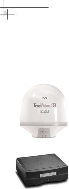
KVH® TracVision G8

 *
*

 *
*
 *
*
 *
*
 *
*
|
|
|
|
|
|
|
|
|
|
|
|
|
|
|
|
|
|
|
|
|
|
|
* |
|
|
|
|
|
** |
|
|
|
|
|
|
||||
|
|
|
|
|
|
|
|
|
|
|
|
|
|
|
|
|
|
|
|
 *
*
Notes
*Press any button to return.
**If GPS is providing valid position data to the antenna, manual entry of latitude/longitude is not available.

Welcome to TracVision G8
TracVision G8
Owner’s Manual
This manual provides detailed instructions on the proper operation, installation, configuration, troubleshooting, and maintenance of the KVH TracVision G8 system. For operation instructions, refer to the Guide to Operation. For installation, configuration, troubleshooting, and maintenance instructions, refer to the Guide to Technical Information.
Throughout this manual, important information is marked for your attention by these icons:
A helpful tip that either directs you to a related area within the manual or
offers suggestions on getting the best performance from your system.
TracVision G8 Serial Number
An alert to important information regarding procedures, product specifications, or product use.
Information about installation, maintenance, troubleshooting, or other mechanical issues.
An electrical safety warning to help identify electrical issues that can be a hazard to either this KVH product or a user.
Direct questions, comments, or suggestions to:
KVH Industries, Inc. |
KVH Europe A/S |
|
50 Enterprise Center |
Ved Klaedebo 12 |
|
Middletown, RI 02842-5279 USA |
2970 Hoersholm Denmark |
|
Tel: +1 401 847-3327 |
Tel: +45 |
45 16 01 80 |
Fax: +1 401 849-0045 |
Fax: +45 |
45 86 70 77 |
E-mail: info@kvh.com |
E-mail: info@kvh.dk |
|
Internet: www.kvh.com |
Internet: www.kvh.com |
|
This serial number will be required for all troubleshooting or service calls made regarding this product.
KVH Part # 54-0198 Rev. C
© 2003 KVH Industries, Inc., All rights reserved.
Fiber optic gyros protected by U.S. and foreign patents
TracVision® , TracNet™, and KVH ® are trademarks of KVH Industries, Inc.
DVB® (Digital Video Broadcasting) is a registered trademark of the DVB Project.
DIRECTV® is an official trademark of DIRECTV, Inc., a unit of GM Hughes Electronics.
DISH™ Network is an official trademark of
EchoStar Communications Corporation.
ExpressVu is a property of Bell ExpressVu, a wholly owned subsidiary of Bell Satellite Services.

Table of Contents
Table of Contents
Guide to Operation . . . . . . . . . . . . . . . . . . . . . . . . . . . . . . . . .1
1 System Overview . . . . . . . . . . . . . . . . . . . . . . . . . . . . . . . . . . . . . .3 2 Receiving Satellite Signals . . . . . . . . . . . . . . . . . . . . . . . . . . . . . .5 3 Turning On the System . . . . . . . . . . . . . . . . . . . . . . . . . . . . . . . . .6 4 Changing Channels and Switching to the Second Satellite . . . . .7 5 Watching Television . . . . . . . . . . . . . . . . . . . . . . . . . . . . . . . . . . . .8 6 Internet Access . . . . . . . . . . . . . . . . . . . . . . . . . . . . . . . . . . . . . . .9 7 Using the MCU Interface . . . . . . . . . . . . . . . . . . . . . . . . . . . . . . .10
Guide to Technical Information . . . . . . . . . . . . . . . . . . . . . . . |
11 |
||
1 |
Introduction . . . . . . . . . . . . . . . . . . . . . . . . . . . . . . . . |
13 |
|
|
1.1 |
System Overview . . . . . . . . . . . . . . . . . . . . . . . . . . . . . . |
15 |
|
1.2 |
System Components . . . . . . . . . . . . . . . . . . . . . . . . . . . . |
17 |
|
1.3 |
Materials Provided with the TracVision G8 . . . . . . . . . . . . |
18 |
2 |
Installation . . . . . . . . . . . . . . . . . . . . . . . . . . . . . . . . |
19 |
|
|
2.1 |
Planning the Installation . . . . . . . . . . . . . . . . . . . . . . . . . |
21 |
|
2.2 |
Mounting the TracVision Antenna . . . . . . . . . . . . . . . . . . . |
26 |
|
2.3 |
Connecting the IRD(s) . . . . . . . . . . . . . . . . . . . . . . . . . . . |
31 |
|
2.4 |
Wiring the MCU . . . . . . . . . . . . . . . . . . . . . . . . . . . . . . . . |
35 |
|
2.5 |
Mounting the MCU . . . . . . . . . . . . . . . . . . . . . . . . . . . . . |
38 |
|
2.6 |
Activating/Programming the IRD . . . . . . . . . . . . . . . . . . . |
40 |
|
2.7 |
Installing Satellites Using the MCU . . . . . . . . . . . . . . . . . |
42 |
|
2.8 |
Checking Out the System . . . . . . . . . . . . . . . . . . . . . . . . |
52 |
|
2.9 |
Changing Geographic Location . . . . . . . . . . . . . . . . . . . . |
54 |
3 Using the MCU Interface . . . . . . . . . . . . . . . . . . . . . . . .57
3.1 Startup and Self-test . . . . . . . . . . . . . . . . . . . . . . . . . . . .59 3.2 Main Display and Accessing the Main Menu . . . . . . . . . .60
54-0198 |
i |
|
|
|
|

TracVision G8 Owner’s Manual
3.3 Installing Satellites . . . . . . . . . . . . . . . . . . . . . . . . . . . . .63
3.4 Restarting the Antenna . . . . . . . . . . . . . . . . . . . . . . . . . .65
3.5 Operations Mode . . . . . . . . . . . . . . . . . . . . . . . . . . . . . . .65
4 Troubleshooting . . . . . . . . . . . . . . . . . . . . . . . . . . . . .81
4.1 Troubleshooting Matrix . . . . . . . . . . . . . . . . . . . . . . . . . .83
4.2Causes and Remedies for Common
|
Operational Issues . . . . . . . . . . . . . . . . . . . . . . . . . . . . |
.84 |
4.3 |
IRD Troubleshooting . . . . . . . . . . . . . . . . . . . . . . . . . . . . |
87 |
4.4 |
Antenna Gyro and LNB Faults . . . . . . . . . . . . . . . . . . . . . |
87 |
4.5 |
Computer Diagnostics . . . . . . . . . . . . . . . . . . . . . . . . . . . |
88 |
4.6 |
Maintenance Port Parser Commands . . . . . . . . . . . . . . . |
89 |
5 Maintenance . . . . . . . . . . . . . . . . . . . . . . . . . . . . . . .91
5.1 Warranty/Service Information . . . . . . . . . . . . . . . . . . . . . .93
5.2 Preventive Maintenance . . . . . . . . . . . . . . . . . . . . . . . . .93
5.3 TracVision G8 Field Replaceable Units . . . . . . . . . . . . . .94
5.4Accessing Antenna Components Through the Hatch . . . .96
5.5 Replacing the PCB Module Fuse . . . . . . . . . . . . . . . . . . .96 5.6 Replacing the Main PCB . . . . . . . . . . . . . . . . . . . . . . . . .97 5.7 Replacing the RF PCB . . . . . . . . . . . . . . . . . . . . . . . . .100 5.8 Replacing the Internal Sensor . . . . . . . . . . . . . . . . . . . .103 5.9 Replacing the Azimuth FOG . . . . . . . . . . . . . . . . . . . . .104 5.10 Replacing the Elevation Gyro . . . . . . . . . . . . . . . . . . . . .106 5.11 Replacing the Roll Gyro . . . . . . . . . . . . . . . . . . . . . . . . .107 5.12 Replacing the Azimuth Motor . . . . . . . . . . . . . . . . . . . . .108 5.13 Replacing the Elevation Motor . . . . . . . . . . . . . . . . . . . .110 5.14 Replacing the Elevation Belt . . . . . . . . . . . . . . . . . . . . .112
5.15Replacing the Skew Motor (European Systems Only) . .113
5.16Replacing the Skew Belt (European Systems Only) . . . .117
5.17 Replacing the LNB . . . . . . . . . . . . . . . . . . . . . . . . . . . .120 5.18 Replacing the LNB/Feed Tube Assembly . . . . . . . . . . . .121 5.19 Preparing for Shipment . . . . . . . . . . . . . . . . . . . . . . . . .123
|
ii |
54-0198 |
|
|
|

Table of Contents
Appendices . . . . . . . . . . . . . . . . . . . . . . . . . . . . . . . . . . . .125
A System Specifications . . . . . . . . . . . . . . . . . . . . . . . . . . . .127
B MCU Flush Mount Panel Template . . . . . . . . . . . . . . . . . . .129
C Comprehensive System Wiring Diagram . . . . . . . . . . . . . .131
D Startup Data Sequences . . . . . . . . . . . . . . . . . . . . . . . . . .133
E Maintenance Port Parser Commands . . . . . . . . . . . . . . . . .135
F Patent Protection . . . . . . . . . . . . . . . . . . . . . . . . . . . . . . . .145
Warranty . . . . . . . . . . . . . . . . . . . . . . . . . . . . . . . . . . . . . . . . . . .147
Index
54-0198 |
iii |
|
|
|
|

Guide to Operation
Guide to Operation
This guide explains everything you need to know to operate your TracVision G8 system. For detailed installation, configuration, troubleshooting, and maintenance information, please refer to the Guide to Technical Information.
Contents
1 System Overview . . . . . . . . . . . . . . . . . . . . . . . . . . . . . . . . . . . . . . .3 2 Receiving Satellite Signals . . . . . . . . . . . . . . . . . . . . . . . . . . . . . . . .5 3 Turning On the System . . . . . . . . . . . . . . . . . . . . . . . . . . . . . . . . . . .6 4 Changing Channels and Switching to the Second Satellite . . . . . . . . .7 5 Watching Television . . . . . . . . . . . . . . . . . . . . . . . . . . . . . . . . . . . . .8 6 Internet Access . . . . . . . . . . . . . . . . . . . . . . . . . . . . . . . . . . . . . . . . .9 7 Using the MCU Interface . . . . . . . . . . . . . . . . . . . . . . . . . . . . . . . . .10
54-0198 |
1 |
|
|
|
|

Guide to Operation
1 |
System Overview |
|
|
|
|
||
A complete satellite TV system, illustrated in Figure 1, includes |
|
|
|
the TracVision G8 antenna unit connected to the Master Control |
|
|
|
Unit (MCU), an IRD (satellite TV receiver), and a television set. |
Figure 1 |
|
|
|
TracVision G8 Antenna |
TracVision G8 System Diagram |
|
|
|
|
|
|
|
European TracVision G8 systems |
|
|
can be connected to four satellite |
9-36 VDC |
|
receivers via four RF cables. |
120 Watts |
|
|
Master Control |
Options Purchased Separately |
|
|
|
|
Unit (MCU) |
Satellite Receiver 1 |
TV 1 |
|
||
Power/Data |
RF |
|
PC Diagnostics
RF
Satellite Receiver 2 |
TV 2 |
System Compatibility
The TracVision G8 is fully compatible with Digital Video Broadcasting (DVB®) satellites, as well as DIRECTV®‘s Digital Satellite Service (DSS) satellites. The system is also fully compatible with KVH’s TracNet™ 2.0 Mobile High-speed Internet System (for more information about TracNet 2.0, please visit our web site at www.kvh.com).
In-motion Tracking
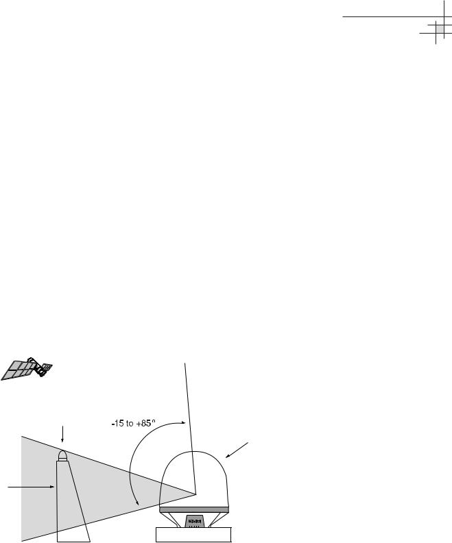
The TracVision G8 uses a state-of-the-art actively stabilized antenna system. The antenna’s built-in global positioning system (GPS) allows the system to calculate the precise azimuth and elevation to the satellite from your vessel’s current location, ensuring the shortest possible satellite acquisition time. Once the satellite is acquired, the antenna gyros continuously measure the heading, pitch, and roll of your vessel and send commands to the antenna motors to keep the antenna pointed at the satellite at all times.
Figure 2
TracVision Identifies and Compensates for Vessel Motion
54-0198 |
3 |
|
|
|
|
TracVision G8 Owner’s Manual - Guide to Operation
Satellite Library
Your TracVision G8 includes a pre-programmed satellite library of North American, European, and Latin American satellite services. If the satellite service you wish to receive is not already in the satellite library, an authorized technician can add two additional satellites of your choice to the library.
System Components
Your TracVision G8 system includes the following components:
Antenna Unit
The antenna unit houses the antenna positioning mechanism, low noise block (LNB), GPS, and three-axis sensor within a molded ABS radome. The European version includes a skew control mechanism that automatically adjusts the antenna’s skew to account for regional changes and different satellite services. Power, signal, and control cabling from belowdecks units are connected to the antenna at the rear of the baseplate.
Master Control Unit
The MCU is the user interface, providing access to the system and its functions through an LCD and three soft keys. The MCU also serves as the system’s junction box, allowing the system to use ship’s power and supply and receive data to/from the TracVision G8. The MCU can accept any power input between 9 and 36 volts DC; its power supply provides power to the antenna and galvanically isolates the TracVision G8 system.
Integrated Receiver Decoder (IRD)
The IRD (purchased separately) receives satellite signals from the antenna unit for signal processing and channel selection, and sends the signals to the TV set for viewing. Please refer to the user’s manual provided with your selected IRD for complete operating instructions.
|
4 |
54-0198 |
|
|
|
Guide to Operation
2 Receiving Satellite Signals
For TracVision G8 to receive satellite TV signals, the antenna must have a clear line of sight to the satellite. If you only receive intermittent signals or the antenna cannot find the satellite, check around your vessel for any objects that could be blocking the signal, such as other vessels, trees, buildings, other onboard equipment, etc.
Figure 3
Be Aware of Objects that Might Block the Satellite Signals
You must also be located within the selected satellite’s coverage area in order to receive its signal. Refer to your satellite television service manual to check the viable coverage area. For your convenience, KVH provides links to several web sites that offer satellite coverage information. Simply go to our web site at: www.kvh.com/ footprint/index.html.
54-0198 |
5 |
|
|
|
|

TracVision G8 Owner’s Manual - Guide to Operation
To minimize the time it takes the antenna to acquire the satellite, do not change the channel during the startup process or cable unwrap.
3 Turning On the System
The TracVision G8 system is easy to use. Antenna unit initialization and satellite acquisition are completely automatic.
To use the TracVision G8 system, follow the steps below.
1.Turn on the IRD and the television. (Refer to your IRD user’s manual for complete operating instructions for the IRD.)
2.Apply power to the TracVision G8 antenna.
3.Minimize turning the vessel for two minutes after turning on the antenna to allow the antenna gyro to initialize properly.
|
6 |
54-0198 |
|
|
|

4Changing Channels and Switching to the Second Satellite
TracVision G8 can have a pair of satellites installed, either one of which can be the active satellite selection. There are several methods of selecting whether your TracVision G8 will track Satellite A or Satellite B based upon your location, type of install, IRD, and selected satellite service.
European Satellite Subscribers
If you are not using a multiswitch, switching from one satellite to the other is as easy as changing the channel using the IRD remote control. TracVision G8 will automatically switch from Satellite A to Satellite B and back again as necessary to receive your selected channel. If you are using a multiswitch, use the MCU switching option described in “Switching Satellites Using the MCU” on
page 8.
DIRECTV Satellite Subscribers
DIRECTV subscribers in certain regions of the United States will require a DSS Plus™ IRD to receive broadcasts from multiple satellites.
If connected to the antenna’s RF1 connector, the DSS Plus IRD allows you to switch channels using the IRD remote control. If you are a DIRECTV subscriber, but do not have a DSS Plus IRD, or you are using a multiswitch, use the MCU switching option described in “Switching Satellites Using the MCU” on page 8.
EchoStar and ExpressVu Satellite Subscribers
EchoStar and ExpressVu subscribers will need to use the MCU switching option, as described in “Switching Satellites Using the MCU” on page 8.
DIRECTV Latin America Subscribers
If your TracVision G8 is equipped for use with the DIRECTV Latin America service, your antenna will search for and receive signals from one satellite (Galaxy 8W or Galaxy 8E). Therefore, there is no need to switch satellites.
Guide to Operation
The satellite configuration on your IRD must match the satellite setting on the TracVision G8 system.
Satellite A on the TracVision G8 must be the same satellite as IRD Alternative 1 (or A, based on your IRD) and must be assigned the IRD DiSEqC 1 setting.*
Satellite B on the TracVision G8 must be the same satellite as IRD Alternative 2 (or B, based on your IRD) and must be assigned the IRD DiSEqC 2 setting.*
Refer to your IRD user manual for complete instructions for your IRD.
*DiSEqC settings only apply to European systems and DIRECTV DSS Plus™ IRDs.
When you switch from one satellite to another, all IRDs connected to the system will receive signals from the new satellite.
54-0198 |
7 |
|
|
|
|

TracVision G8 Owner’s Manual - Guide to Operation
Switching Satellites Using the MCU
If you’re unable to switch between satellites using the IRD remote control, use the MCU front panel buttons to select between Satellite A and Satellite B. Press the left button to select Satellite A and the right button to select Satellite B.
Figure 4
Switching Satellites Using
the MCU
European systems only:
Using the MCU to switch between satellites disables the system’s DiSEqC monitoring. You will not be able to use the IRD to switch between satellites unless the system is restarted.
Track Installed |
Track Installed |
Satellite A |
Satellite B |
5 Watching Television
TracVision G8 is designed to operate as efficiently and as reliably as possible both when your vessel is in motion and at rest.
Cable Unwrap
The antenna can rotate a full 720° before reaching the end of its cable. If it does so, the system automatically unwraps the cable by quickly rotating the dish in the opposite direction. During this time, your television transmission will freeze momentarily while the cable unwraps and the antenna reacquires the satellite.
Conical Scan Tracking
The antenna uses conical scanning to maintain peak signal strength to the receiver and to update the satellite’s position. When conical scan tracking is active, the antenna moves continually in a circular motion to sweep across the satellite’s peak signal. The signal strength is then fed back to the control circuits to keep pointed in the direction of the strongest signal.
If the satellite signal is lost while the system is in conical scan track mode, the control software imposes a 15-second time-out delay. If the signal is not regained during that time, the antenna will search for the satellite signal. This is an automatic process that does not require user intervention.
|
8 |
54-0198 |
|
|
|

Sleep Mode
When the vessel has come to a stop and holds its position for one minute (e.g., at a dock), the antenna unit enters Sleep Mode, which locks the antenna in place to conserve power. As soon as the vessel moves beyond a 1° - 2° window, or the RF level changes significantly, Sleep Mode automatically turns off and the system begins tracking the satellite again (or enters Search mode to find the satellite).
6 Internet Access
Your TracVision G8 can receive high-speed Internet data when used in conjunction with KVH’s TracNet 2.0 Mobile High-speed Internet System. With TracNet 2.0, you get broadband Internet access on the move via satellite downloads and a wireless return path. For more information about TracNet 2.0 in North America and Europe, please visit our web site at www.kvh.com.
Guide to Operation
If you prefer, you may disable the Sleep Mode function. Refer to
“Turning Sleep Mode On/Off”on page 70 for details.
54-0198 |
9 |
|
|
|
|

TracVision G8 Owner’s Manual - Guide to Operation
7 Using the MCU Interface
All TracVision G8 operations are controlled and monitored using the MCU. An LCD display shows configuration data and three soft keys enable you to perform basic menu-driven tasks.
Figure 5
MCU Front Panel
LCD Display
Soft Keys
Table 1
Commonly Used Menu Functions
During the TracVision G8 installation process, the satellite selections should have been configured to your specifications as detailed in the Guide to Technical Information. Once the system is installed and functioning properly, the system will function automatically.
However, there may be instances in which you need to access certain settings via the MCU interface. To assist you, KVH has provided the following information resources:
Quick Reference Guide:
The quick reference guide on the inside front cover of this manual illustrates the main display and the overall menu structure, allowing you to easily and quickly navigate among the MCU menus.
Section 3 in the Guide to Technical Information:
Section 3, “Using the MCU Interface,” on page 57 of the Guide to Technical Information provides a detailed explanation of every menu option and system configuration setting. These menus should, for the most part, be accessed by authorized technicians. The following are the most commonly used menu functions:
Menu Function |
Purpose |
See Page: |
|
|
|
Install Satellite |
Install a satellite to track |
63 |
|
|
|
Set Sleep On/Off |
Turn Sleep Mode on or off |
70 |
|
|
|
Set Brightness |
Adjust the MCU display’s brightness |
80 |
|
|
|
|
10 |
54-0198 |
|
|
|

Guide to Technical Information
Guide to Technical
Information
This guide explains how to install, troubleshoot, and maintain the TracVision G8 system. For complete operation instructions, please refer to the Guide to Operation at the front of this manual.
Contents
1 Introduction . . . . . . . . . . . . . . . . . . . . . . . . . . . . . . . . . . . . . . . . . .13
2 Installation . . . . . . . . . . . . . . . . . . . . . . . . . . . . . . . . . . . . . . . . . . .19
3 Using the MCU Interface . . . . . . . . . . . . . . . . . . . . . . . . . . . . . . . . .57
4 Troubleshooting . . . . . . . . . . . . . . . . . . . . . . . . . . . . . . . . . . . . . . .81
5 Maintenance . . . . . . . . . . . . . . . . . . . . . . . . . . . . . . . . . . . . . . . . . .91
Appendices . . . . . . . . . . . . . . . . . . . . . . . . . . . . . . . . . . . . . . . . . . . . . . . .125
54-0198 |
11 |
|
|
|
|

Introduction
1 – Introduction
This section provides a basic overview of the TracVision G8 system. It explains how the system works and describes the function of each component.
Contents
1.1 System Overview . . . . . . . . . . . . . . . . . . . . . . . . . . . . . . . . . . . .15 1.2 System Components . . . . . . . . . . . . . . . . . . . . . . . . . . . . . . . . .17 1.3 Materials Provided with the TracVision G8 . . . . . . . . . . . . . . . . .18
54-0198 |
13 |
|
|
|
|

Introduction
1.1System Overview
A complete satellite TV system, illustrated in Figure 1-1, includes the TracVision G8 antenna unit connected to the Master Control Unit (MCU), an IRD (satellite TV receiver), and a television set. A desktop or laptop computer is used to conduct diagnostics.
System specifications are provided in Appendix A on page 127.
TracVision G8 Antenna
Figure 1-1
TracVision G8 System Diagram
European TracVision G8 systems
9-36 VDC |
|
can be connected to four satellite |
120 Watts |
|
receivers via four RF cables. |
Master Control |
Options Purchased Separately |
|
|
|
|
Unit (MCU) |
Satellite Receiver 1 |
TV 1 |
|
||
Power/Data |
RF |
|
PC Diagnostics
RF
Satellite Receiver 2 |
TV 2 |
System Compatibility
The TracVision G8 satellite antenna is fully compatible with Digital Video Broadcasting (DVB®) satellites, as well as DIRECTV®‘s Digital Satellite Service (DSS) satellites. The system is also fully compatible with KVH’s TracNet™ 2.0 Mobile High-speed Internet System (for more information about TracNet 2.0, please visit KVH’s web site at www.kvh.com).
In-motion Tracking
Figure 1-2
TracVision Identifies and Compensates for Vessel Motion
The TracVision G8 uses a state-of-the-art actively stabilized antenna system. The antenna’s built-in GPS allows the system to calculate the precise azimuth and elevation to the satellite from your vessel’s current location, ensuring the shortest possible satellite acquisition time. Once the satellite is acquired, the antenna gyros continuously measure the heading, pitch, and roll of your vessel and send commands to the antenna motors to keep the antenna pointed at the satellite at all times.
54-0198 |
15 |
|
|
|
|

TracVision G8 Owner’s Manual - Guide to Technical Information
Satellite Library
TracVision G8’s default satellite pairs are:
N. America (US DIRECTV):
DSS_101 & DSS_119
Europe:
Astra1 & HotbirdWB
L. America (DIRECTV LA):
Galaxy_8W & None
Table 1-1
Available Satellite Pairs
- North America
(North American LNB Required)
Your TracVision G8 includes a pre-programmed satellite library of North American, European, and Latin American satellite services. When configuring the TracVision G8, you may choose a pair of satellites from the library to be active in the system and with your IRD.
Table 1-1 lists the possible satellite pairs that may be selected in North America, and Table 1-2 lists the satellites that can be programmed in Europe (as long as the paired satellites are within range of the TracVision antenna). In Latin America, the system can track either Galaxy_8W or Galaxy_8E to receive DIRECTV Latin America service (Latin American LNB required). If the satellite service you wish to receive is not listed in the satellite library, you may add two additional satellites of your choice to the library.
|
DSS_101 |
DSS_119 |
Echo_61 |
Echo_110 |
Echo_119 |
Echo_148 |
Expressvu |
ExpressTV |
DSS_101 |
|
|
|
|
|
|
|
|
|
|
|
|
|
|
|
|
|
DSS_119 |
|
|
|
|
|
|
|
|
Echo_61 |
|
|
|
|
|
|
|
|
|
|
|
|
|
|
|
|
|
Echo_110 |
|
|
|
|
|
|
|
|
Echo_119 |
|
|
|
|
|
|
|
|
|
|
|
|
|
|
|
|
|
Echo_148 |
|
|
|
|
|
|
|
|
Expressvu |
|
|
|
|
|
|
|
|
|
|
|
|
|
|
|
|
|
ExpressTV |
|
|
|
|
|
|
|
|
|
|
|
|
|
|
|
|
|
Table 1-2
Available Satellites - Europe
(European LNB/Feed Tube
Assembly Required)
Any two of the European satellites listed below can be paired together, as long as the satellites are within range of the antenna:
• |
Astra1 |
• |
Sirius |
• |
Astra2N |
• |
Thor |
• |
Astra2S |
• |
Arabsat |
• |
Hispasat |
• |
Nilesat |
• |
HotbirdWB |
• |
Optus_B1 |
• |
Hotbird |
• |
Optus_B3 |
|
16 |
54-0198 |
|
|
|
1.2System Components
Your TracVision G8 system includes the following components:
Antenna Unit
The antenna unit houses the antenna positioning mechanism, low noise block (LNB), GPS, and three-axis sensor within a molded ABS radome. The European version includes a skew control mechanism that automatically adjusts the antenna’s skew to account for regional changes and different satellite services. Power, signal, and control cabling from belowdecks units are connected to the antenna at the rear of the baseplate.
Master Control Unit (MCU)
The MCU is the user interface, providing access to the system and its functions through an LCD and three soft keys. The MCU also serves as the system’s junction box, allowing the system to use ship’s power, and supply and receive data to/from the TracVision G8. The MCU can accept any power input between 9 and 36 volts DC; its power supply provides power to the antenna and galvanically isolates the TracVision G8 system.
Integrated Receiver Decoder (IRD)
The IRD (purchased separately) receives satellite signals from the antenna unit for signal processing and channel selection, and sends the signals to the TV set for viewing. Please refer to the user’s manual provided with your selected IRD for complete operating instructions.
Introduction
Before you can start watching satellite TV using your TracVision antenna, you will need to activate your IRD. Refer to Section 2.6, “Activating/Programming the IRD,” on page 40 for details.
54-0198 |
17 |
|
|
|
|
TracVision G8 Owner’s Manual - Guide to Technical Information
1.3Materials Provided with the TracVision G8
Table 1-3 lists the components and materials in the TracVision G8 shipping carton.
Table 1-3
TracVision G8 Packing List
For a list of items supplied in the kitpack, see Table 2-3 on page 22.
Component |
KVH Part No. |
|
|
|
|
Antenna unit |
02-1262-01† |
|
|
|
02-1262-03†† |
|
|
02-1262-04††† |
|
|
|
Master control unit (MCU) |
02-1265 |
|
|
|
|
Installation kitpack |
72-0127 |
|
|
|
|
Data/power cable, 100 ft. (30 m) |
32-0744-100 |
|
|
|
|
TracVision G8 Owner’s Manual |
54-0198 |
|
|
|
|
† |
North American system |
|
†† |
Latin American system |
|
††† |
European system |
|
|
18 |
54-0198 |
|
|
|

Installation
2 – Installation
This section explains how to install, configure, and test the TracVision G8 system. Follow the simple procedures in this section sequentially to ensure a safe and effective installation.
Contents
2.1 Planning the Installation . . . . . . . . . . . . . . . . . . . . . . . . . . . . . . .21
2.2 Mounting the TracVision Antenna . . . . . . . . . . . . . . . . . . . . . . . .26
2.3 Connecting the IRD(s) . . . . . . . . . . . . . . . . . . . . . . . . . . . . . . . .31
2.4 Wiring the MCU . . . . . . . . . . . . . . . . . . . . . . . . . . . . . . . . . . . . .35
2.5 Mounting the MCU . . . . . . . . . . . . . . . . . . . . . . . . . . . . . . . . . . .38
2.6 Activating/Programming the IRD . . . . . . . . . . . . . . . . . . . . . . . .40
2.7 Installing Satellites Using the MCU . . . . . . . . . . . . . . . . . . . . . . .42
2.8 Checking Out the System . . . . . . . . . . . . . . . . . . . . . . . . . . . . . .52
2.9 Changing Geographic Location . . . . . . . . . . . . . . . . . . . . . . . . . .54
54-0198 |
19 |
|
|
|
|

2.1Planning the Installation
Who Should Install the TracVision G8
KVH recommends that a KVH-authorized technician install the TracVision G8 system. Installers should have experience installing electronic equipment on a vessel.
Materials and Equipment Required for Installation
Before you begin installing the TracVision G8 system, you need to verify that you have all of the following tools and materials:
•Electric drill and 1⁄2" (13 mm) drill bit
•17 mm socket wrench
•9⁄16" open-end wrench
•Flat head and Phillips screwdrivers
•Light hammer; center punch; tape; scriber/pencil
•Wire strippers
•A PC with terminal emulation software such as Windows Hyperterminal or PROCOMM
•Quick-tripping circuit breaker or fuse rated for 30 amps
•RG-11 cable(s) with F-type connectors (refer to Table 2-1 to determine the number of RF cables needed)
Connecting to: |
# RF Cables |
|
|
North American Systems |
|
|
|
One IRD |
1 |
|
|
Two IRDs |
2 |
|
|
Two or more IRDs |
2* |
|
|
European Systems |
|
|
|
One IRD |
1 |
|
|
Two IRDs |
2 |
|
|
Three IRDs |
3 |
|
|
Four IRDs |
4 |
|
|
More than four IRDs |
4* |
|
|
* Multiswitch required. Follow manufacturer’s guidelines.
Installation
Plan the entire installation before proceeding! Take into account antenna unit placement, cable running distances between units, and accessibility to the equipment after installation.
If you are prewiring the system, be sure to route the N-type connector end of the data/power cable to the antenna location and the F-type connector end to the belowdecks MCU (see Figure 2-8 on page 28).
RG-11 with F-type connectors is required for all RF wiring. Use of any other cable will result in degraded performance, which is not covered by the KVH warranty.
Table 2-1
Number of RF Cables to Connect to the Antenna
You may want to connect four RF cables to the antenna in all cases. That way, if an IRD is added (or the system is converted from North American to European use) in the future, no additional RF cables will need to be run.
54-0198 |
21 |
|
|
|
|

TracVision G8 Owner’s Manual - Guide to Technical Information
Table 2-2
Recommended MCU-to-Ship’s
Power Cable Specifications
•Power cable to connect the MCU to ship’s power (Table 2-2 provides proper gauge and length specifications for a 12V supply. The system will not work if the MCU receives less than 9V).
Cable Length |
Cable Gauge |
|
|
to 40 ft (12 m) |
12 AWG (1.5 mm2) |
up to 70 ft (21 m) |
10 AWG (2.5 mm2) |
Table 2-3
Kitpack Contents
Kitpack Contents
The kitpack packaged with your system contains hardware and other materials that will be needed to complete the installation. Ensure that the kitpack contains all of the items listed below.
Part |
Part # |
Qty. |
|
|
|
M10 x 1.5 x 50 mm hex head bolts |
14-0342-50 |
4 |
|
|
|
M10 flat washers |
14-0344-10 |
4 |
|
|
|
M10 lock washers |
14-0343-10 |
4 |
|
|
|
M4 x 0.7 x 8 mm pan-head Phillips screws |
14-0075-08 |
6 |
|
|
|
Plastic screw covers |
19-0088 |
8 |
|
|
|
Rear logo plate |
20-0885-02 |
1 |
|
|
|
Power connector plug |
23-0497-02 |
1 |
|
|
|
IRD ground cable |
32-0583-50 |
1 |
|
|
|
PC cable (for diagnostics) |
32-0628-06 |
1 |
|
|
|
PC cable gender changer |
23-0517-09 |
1 |
|
|
|
Flush mount MCU bracket |
20-0667 |
1 |
|
|
|
Velcro self-adhesive backings |
19-0146 |
4 |
|
|
|
Velcro washers |
19-0147 |
4 |
|
|
|
#4-24 thread-forming screws |
14-0150-06 |
4 |
|
|
|
Tie-wraps |
22-0006 |
5 |
|
|
|
#8 type A screws |
14-0047-08 |
4 |
|
|
|
#8 lock washers |
14-0038 |
4 |
|
|
|
#6-32 x 1⁄2" pan head screws |
14-0029-08 |
2 |
|
|
|
#6 flat washers |
14-0024 |
2 |
|
|
|
Small Ferrite Coil |
29-0088 |
1 |
|
|
|
Large Ferrite Coil |
29-0090 |
1 |
|
|
|
F-type connector |
23-0213 |
1 |
|
|
|
|
22 |
54-0198 |
|
|
|
Installation
Choosing Component Locations
When determining component locations, first keep in mind accessibility and cable lengths between units. For example, since the data/power cable is 100 ft (30 m) long, the MCU must be located within 100 ft (30 m) of the antenna.
The major considerations in locating the TracVision components are described below.
Choosing the Best Location for the TracVision Antenna
There are several factors to consider when choosing the location for the TracVision antenna.
•Since the TracVision antenna requires a clear view of the southern sky to receive satellite signals, the ideal antenna site has an unobstructed view of the horizon/satellite all around. The less blockage, the better the system performs.
•Keep the antenna clear of any obstructions above decks. The antenna requires a -15º to +85º look angle to receive satellite signals.
Figure 2-1
Antenna Blockage
Blocked!
TracVision Antenna
Mast
Vessel Platform
•To minimize tracking errors, place the antenna unit as close as possible to the intersection of the vessel’s fore-and-aft centerline and midships. The antenna unit need not be located exactly on the vessel’s fore-and-aft axis, but its centerline MUST be parallel to it.
54-0198 |
23 |
|
|
|
|

TracVision G8 Owner’s Manual - Guide to Technical Information
•The mounting surface should be flat and strong enough to carry the complete assembly (85 lbs/ 38.6 kg). To prevent warpage to the antenna baseplate, make sure that the mounting surface is rigid so that it cannot flex when the vessel vibrates. If necessary, add a strength member to the mounting site to stiffen it.
•Be sure to account for the height and base dimensions (see Figure 2-2 on the following page). Also be sure to leave enough space outside the access hatch to allow a technician to remove the seven hatch screws and perform maintenance through the hatch.
•Maintain at least four feet (1.3 m) separation between the antenna and any magnetized materials, large ferrous masses, cranes, engines, derricks, other antennas, cables carrying high amperage direct current, or battery banks. Take extra care when mounting the antenna on a steel vessel; use an aluminum, brass, plastic, or wood (NOT steel or iron) platform to position the antenna at least four feet (1.2 m) above and six feet (1.8 m) away from the steel surface.
•Be alert for devices that change their magnetic characteristics when in use, such as CRTs (computer and TV screens), radar magnetrons, electric winches, loudspeakers, windshield wipers, and other devices with DC motors. The antenna’s internal sensor cannot compensate for changing magnetic fields created by these devices.
Radar Concerns
The TracVision antenna must be kept out of line with nearby radars, as their energy levels (from both the main beam and its side lobes) may overload the antenna’s front-end circuits. In an ideal installation, the antenna is mounted four feet (1.2 m) above and four feet (1.2 m) away from the radar (measured from the center of the antenna dome to the center of the radar).
The best placement for the TracVision antenna is above the radar. However, if there will be a significant horizontal separation between the radar and TracVision dome (i.e., at least 8 to 10 feet (2.4 to 3 meters)), the TracVision antenna can be placed below the radar as there will be little chance of signal blockage.
|
24 |
54-0198 |
|
|
|

38.86" (987 mm)
 Access Hatch
17" (432 mm)
4x  .50"
.50"
(4x  13 mm)
|
35" |
( |
889 mm) |
|
12" |
|
(305 mm) |
|
6" |
|
(152 mm) |
|
6" |
|
(152 mm) |
|
12" |
|
(305 mm) |
FWD
Choosing the Best Location for the MCU
•The MCU should be mounted in a dry location, allowing enough room at the back for connecting system cables.
•The MCU should be placed so that the LCD display is visible and the buttons are accessible to the user.
•The MCU is not susceptible to magnetic interference and does not need to be mounted on a level surface.
Installation
Figure 2-2
Antenna Unit Dimensions
The radome exterior is treated with a special finish selected for
compatibility with the dome material and transparency to the satellite signals. Application of additional paints or finishes WILL degrade performance, potentially beyond acceptable limits.
A full-size template of the baseplate mounting holes has been provided at the back of this manual.
Four small holes have been drilled into the bottom of the baseplate to ensure that any moisture that enters the antenna unit is able to drain. Be sure these drain holes do not become blocked.
54-0198 |
25 |
|
|
|
|
TracVision G8 Owner’s Manual - Guide to Technical Information
2.2Mounting the TracVision
Antenna
1.Make sure that you have chosen a suitable mounting location based upon the guidelines in “Choosing the Best Location for the TracVision Antenna” on page 23.
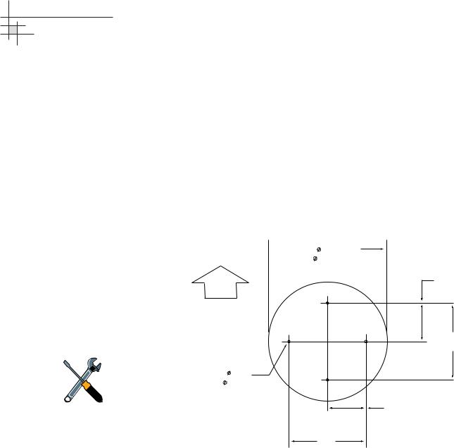
2.Using the template provided at the back of this manual or the dimensions shown in Figure 2-3, lay out the four mounting bolt holes. Make certain that the “Forward” arrow is parallel with the vessel’s centerline and pointed toward the bow.
Figure 2-3
Baseplate Footprint
Antenna Mounting Holes Layout  17"
17"
( 432 mm)
FWD
6"
(152 mm)
A full-size template of the baseplate mounting holes has been provided at the back of this manual.
12"
(305 mm)
4 x 0.5" (4 x 13 mm)
6"
(152 mm)
12" (305 mm)
3.Drill the four 1⁄2" (13 mm) bolt holes following the layout in Step 2.
4.If mounting the antenna on a deck:
Mark a location aft of the antenna for the cable access hole. The hole must be large enough to accommodate the data/power cable and all required RF cables (see Table 2-1 on page 21 to determine the number of RF cables required). Cut out the access hole and smooth the edges of the hole to protect the cables.
5.Remove the antenna unit from its shipping carton.
|
26 |
54-0198 |
|
|
|

6.Remove the eight screws securing the radome to the baseplate. Carefully lift the radome straight up until clear of the antenna assembly and set it aside in a safe place. If you bring the radome topside, secure it with a lanyard to prevent it from falling overboard.
7.Remove the tie-wrap securing the MCU/kitpack box to the antenna baseplate. Remove the box.
Tie-wrap
8.Unfasten the tie-wrap securing the antenna frame to the sensor bracket (release the tab using a flat-head screwdriver). Save the tie-wrap in case the antenna needs to be reshipped someday.
Sensor
Bracket
Frame
Tie-wrap
9.Inspect the antenna unit for any signs of shipping damage.
Installation
Figure 2-4
MCU/Kitpack Box
Figure 2-5
Antenna Frame Shipping Restraint
54-0198 |
27 |
|
|
|
|
Loading...