

Page 1

FILE: IM_091-141_Rev_B
DATE: 10-02-03
INSTRUCTION MANUAL
LOAD MANAGER P
A battery protector for vehicles with equipment that
Is operated with the engine not running
MODEL# 091-141
INPUT: 12 Volts D.C.
MODEL# 091-141-24
INPUT: 24 Volts D.C.
3 YEAR WARRANTY
Page 2

INTRODUCTION
The model 091-141 LOAD MANAGER P is designed to disconnect loads when
the battery voltage drops below a certain threshold. In addition a "Shutdown
Timer" is provided so that the load is disconnected 1 to 2 hours after the engine
is shutdown. This provides the ideal control for the computer or radio in police
cars, rescue vehicles, command vehicles or any application where these devices
might be used with the engine not running. If the operator forgets to shut down
the computer or radio, the battery is protected, as the Load Manager P will turn
off the power before the battery is drained.
12VDC Operation:
The factory pre-set voltage for shutdown is 11.0 volts, but can be
potentiometer adjusted up to 12.85 volts. The factory pre-set shutdown
time is 1 hour (when engine is not running). This time can also be
potentiometer adjusted up to 2 hours.
24VDC Operation:
The factory pre-set voltage for shutdown is 22.0 volts, but can be
potentiometer adjusted from 21.25 to 24.75 volts. The factory pre-set
shutdown time is 1 hour (when engine is not running). This time can also
be potentiometer adjusted up to 2 hours.
Shutdown Timer:
Enabled (factory default) when diode CR4 is installed on Printed Circuit
Board Assembly (refer to Figure 3). Disabling the Shutdown Timer by
removing CR4 will allow load power supply regardless of engine
running/not running status. The load will, however, still be managed as a
function of vehicle battery voltage per voltage shutdown described above.
The Load Manager Model Number will be followed by "DIS" if the Shutdown
Timer is disabled at the factory per customer order.
Page 3
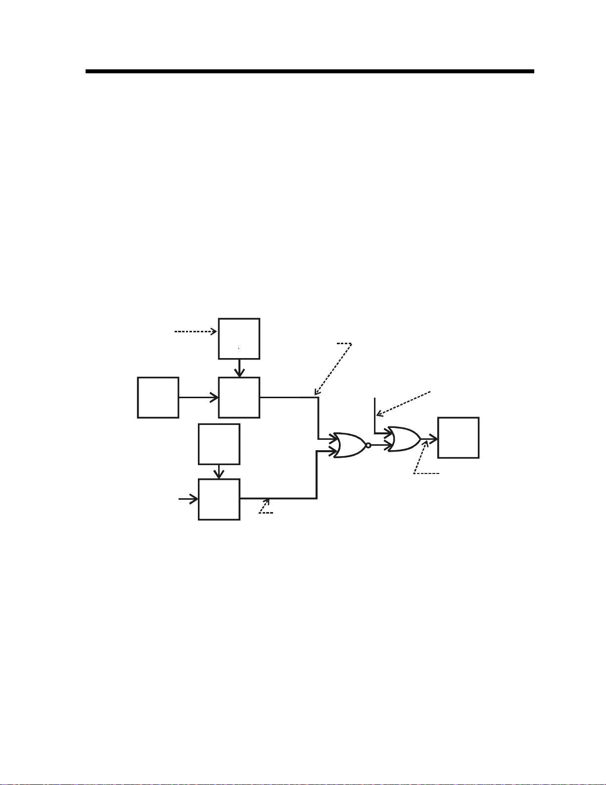
PRINCIPLES OF OPERATION
The Load Manager P is basically a low voltage disconnect which removes power
from the load when the voltage sensed drops below the preset threshold of 11.0
volts for 12VDC operation and 22.0 volts for 24VDC operation. A starter override
is provided to prevent disabling the load while the engine is cranking. This
eliminates re-booting the computer if cranking the engine drops the battery
voltage below the threshold. When the device detects that the engine is not
running a timer is started. After the set time has elapsed the load will be
deenergized. If during the timing cycle, the battery voltage drops below its set
point, the load will be immediately deenergized. Starting the engine at any time
during the timing cycle will reset the timer. A block diagram appears in figure 1.
FACTORY ADJUSTED
TO 1 HOUR
ENGINE
OFF
SENSOR
V
Bat
PRE-SET
ADJUST
TRIMMER
TIMER
1 HOUR
2 HOURS
VOLTAGE
PRE-SET
ADJUST
TRIMMER
VOLTAGE
DETECTOR
TIME
AND ENGINE IS “OFF”
TO
>
T
T
IF TRUE
Sp
STARTER
SWITCH “ON”
V
<
V
IF TRUE
Bat Sp
Figure 1
BLOCK DIAGRAM, LOAD MANAGER P
TRUE WHILE
ENGINE IS
“CRANKING”
POWER
RELAY
IF THIS LINE IS
TRUE, THEN THE
POWER RELAY
IS ENERGIZED
Page 4

INSTALLATION
WIRING:
Figure 2 illustrates the wiring of the Load Manager P. Wire the unit using the
wire gauges shown in figure 2.
RADIO &
COMPUTER
+
LOADS
-
SIZE FUSE
FOR 25% HIGHER
THAN ACTUAL
LOAD
#12 AWG, RED
#12 AWG, ORANGE
NO
C
#12 AWG, BLACK
FROM
12 or 24
VOLT
BATTERY
1
#20 AWG, RED
#20 AWG, BLACK
FROM
STARTER
SWITCH
(0PTIONAL)
23
4
#20 AWG,
YELLOW
Figure 2
INSTALLATION WIRING, LOAD MANAGER P
ALIGNMENT:
Refer to Figure 3 for all component locations and measurement points.
12VDC Operation:
R102 is normally set maximum counter-clockwise for an 11.0 volt threshold.
R102 can be adjusted in a clockwise direction to obtain a higher threshold
voltage. Maximum clockwise is 12.85 volts.
24VDC Operation:
R102 is normally set approximately 70% of full counter-clockwise for a 22.0 volt
threshold. R102 can be adjusted in a clockwise direction to obtain a higher
threshold voltage. Maximum clockwise is 24.75 volts, maximum counterclockwise is 21.25VDC.
R103 is normally set maximum counter-clockwise for a 1-hour time threshold.
R103 can be adjusted in a clockwise direction to obtain a longer time threshold.
Maximum clockwise is 2 hours.
Page 5

Shutdown Timer
Enable Diode
TIME ADJUSTMENT R1 03
MAX. CCW = 1 HOUR (NORMAL)
MAX. CW = 2 HOURS
VOLTAGE ADJUST, R102, 12VD C
R101
R7
C11
R103
+
U3
TIME
C10
R2
CR1
R9
REF
V
U2
+
C9
CR4
C8
+
+
C3
Q1
A3
R4
VOLTS
A1
+
A2
R1
R102
R5
R8
MAX CCW = 11 VOLTS (NORMAL)
MAX CW = 12.85 VO LTS
U1
R3
C1
+
C2
R11
S1
RUN
C13
TEST
+
C6
+
K1
+
B091-141-001
Q2
A4
+
C5
R10
R12
C7
CR3
R6
J1
KUSSMAUL ELECTRONICS
C12
CR2
Figure 3
VOLTAGE ADJUST, R102, 24VD C
MAX CCW = 21 .2 5 VOLTS
MAX CW = 24.75 VOLTS
70% MAX CCW = 22.0 VOL TS (NORMAL)
ALIGNMENT & PROGRAMMING, LOAD MANAGER P
Page 6

SPECIFICATION AND OUTLINE
Temperature Environment: 0 to 50 deg C.
Main Input Power: 12VDC Battery, [24VDC Battery]
Input Current: 90 [40] milliamperes, relay ON
9 [5] milliamperes, relay OFF
Load Output Power: 12VDC @ 30 amperes maximum.
[14VDC @ 30 Amperes maximum]
Low Voltage Dropout of Load: 11.0 to 12.85 volts (potentiometer adjustable,
Factory set for 11 volts).
[21.25 to 24.75 volts (potentiometer adjustable,
Factory set for 22.0 volts)]
Load Power Restoration Voltage: .5 [.75] volt higher than the Low Voltage
dropout of load.
Time Dropout of Load: 1 to 2 hours (potentiometer adjustable, factory
set for 1 hour).
Starter Inhibit: The Load will not drop out due to low voltage
while the engine is being started.
Weight: 0.5 lbs
5.10
3/16" DIA.
2.95
4,50
1.55
OUTLINE, LOAD MANAGER P
Page 7

INSTALLATION RECORD & WARRANTY
Date Installed________________________________________
Installed By___________________________________________
Vehicle Identification_________________________________
Vehicle Owner________________________________________
WARRANTY
All products of Kussmaul Electronics Company Inc. are warranted to be free of
defects of material or workmanship. Liability is limited to repairing or replacing at
our factory, without charge, any material or defects that become apparent in
normal use within 3 years from the date the equipment was shipped. Equipment
is to be returned, shipping charges prepaid and will be returned, after repair,
shipping charges paid.
Kussmaul Electronics Company, Inc. shall have no liability for damages of any
kind to associated equipment arising from the installation and /or use of the
Kussmaul Electronics Company, Inc. products. The purchaser, by the
acceptance of the equipment, assumes all lia bility for any damages which may
result from its installation, use or misuse, by the purchaser, his or its employees
or others.
 Loading...