

Page 1

FILE: 091-139-002
REV.A: 2/24/04
DATE: 04-23-01
INSTRUCTION MANUAL
AUTO ISOLATOR I
AN AUTOMATIC LOSSLESS BATTERY ISOLATOR
FOR DUAL BATTERY SYSTEMS
MODEL# 091-139-2-12
BATTERY VOLTAGE: 12 VDC
OUTPUT: 12 VOLTS, 3 AMPS
BATTERY PARALLELING SOLENOID: 200 AMPS
3 YEAR WARRANTY
Page 2
INTRODUCTION
The Model 091-139-2-12 AUTO ISOLATOR I system is a lossless isolator
replacement for the conventional diode isolator. Designed to be installed in a
vehicle with one or more Main batteries that must be isolated from one or more
auxiliary batteries. The system consists of a voltage detector and controller
Model 091-139-CONT-12 and a separate 200-ampere rated solenoid, Model
091-139-SOL-12HO for switching the batteries. In addition to maintaining battery
isolation the AUTO ISOLATOR I may parallel the batteries on engine starting if
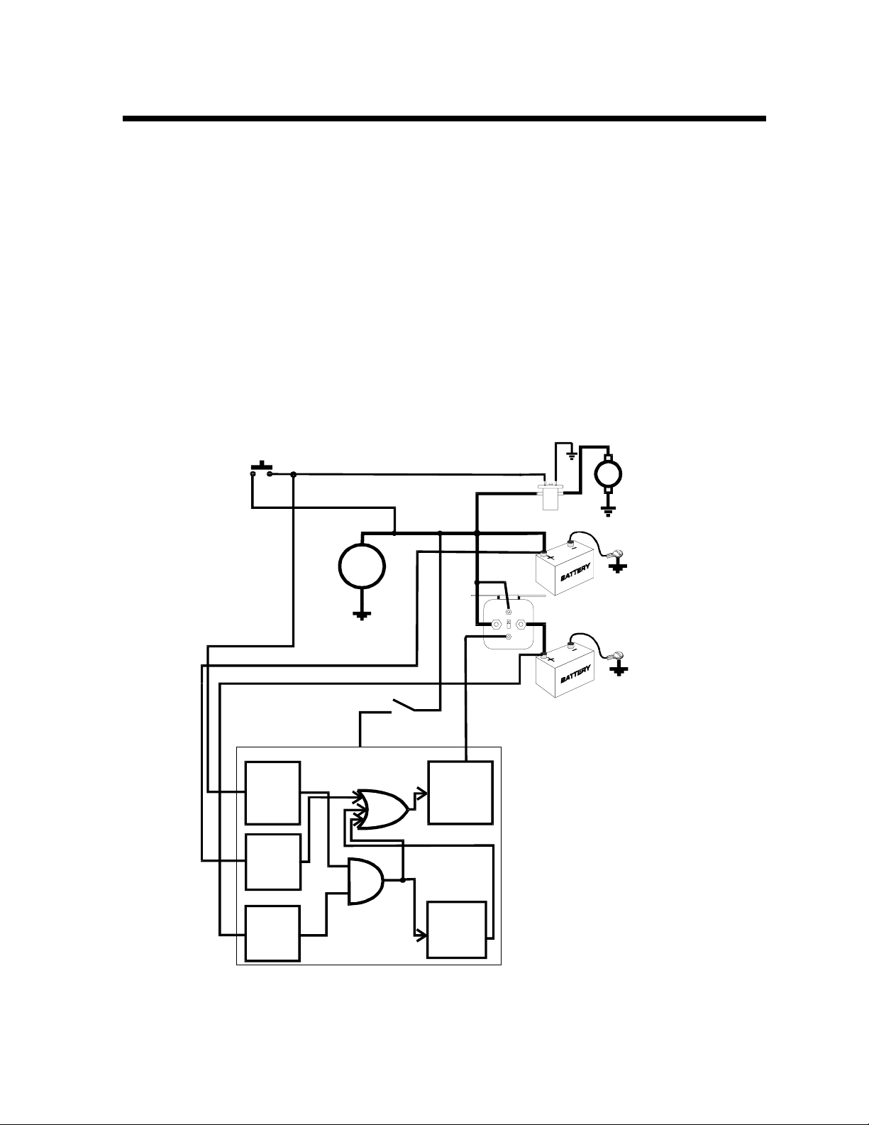
the auxiliary battery has sufficient charge to assist in the cranking. A block
diagram of the system appears in figure 1.
STARTER
PUSH BUTTON
STARTER
ISOLATOR
ALTERNATOR
MAIN BATT ERY SENSE
AUXILIARY BATTERY SENSE
POWER
IGNITIO N
SWITCH
PARALLELING
SOLENOID
DRIVER
SOLENOID
STARTER
SOLENOID
MAIN
BATTERY
AUXILIARY
BATTERY
MAIN
BATTERY
VOLTAGE
DETECTOR
AUX.
BATTERY
VOLTAGE
DETECTOR
TIMER
Figure 1
Block Diagram
Page 3

SYSTEM OPERATION
The system receives its power from the ignition switch. With the switch “OFF” all
the power is removed from the system and the solenoid is deenergized.
As soon as the operator turns the ignition “ON”, the system is powered and
detects the voltage of the main and auxiliary batteries. If the auxiliary battery
voltage is 12.4 volts or greater, (indicating sufficient charge) cranking the engine
will cause the paralleling solenoid to be energized. A 10-second timer will
maintain the paralleling solenoid if the engine doesn’t start immediately and must
be cranked a second time. When the engine starts the alternator output raises
the battery voltage. This increase in voltage is detected and the paralleling
solenoid is held energized charging both batteries.
If when the engine is started the auxiliary battery voltage is below 12.0 volts the
paralleling solenoid is not energized while cranking. As soon as the engine
starts, the alternator raises the main battery voltage and the solenoid is
energized charging both batteries.
Upon engine shutdown the ignition switch is placed in the “OFF” position. Power
is removed from the Auto Isolator and the solenoid is deenergized.
Page 4

INSTALLATION
R
M
H
Install the 091-139-CONT-12 Controller is a suitable location protected from the
weather and engine heat. The 091-139-SOL-12HO Solenoid may be mounted in
the engine compartment or at a location to minimize the length of the battery
cables. Install wiring per figure 2.
THIS LINE ENERGIZES THE
SOLENOID AT ENGINE START
IF THE AUXILIARY BATTERY
HAS SUFFICIENT VOLTAGE
TO PROVIDE A BOOST
THIS LINE SUPPLIES
THE POWER TO OPERATE
THE SYSTEM
AUTO ISOLATOR I CONTROLLER
091-139-CONT-12
12VOLT
RO
GNITION
WITC
1 2 3 4 5 6 7 8
PARALLELING
SOLENOID
SENSE LINE, CONNECT
DIRECTLY TO BATTERY
NOTE POLARITY OF
MAIN
BATTERY
FLYBACK DIODE
ALL WIRES #16 AWG EXCEPT AS NOTED
Note: Red Dot
SENSE LINE, CONNECT
DIRECTLY TO BATTERY
#2 AWG MIN.
+12VOLT
FROM
STARTE
AUXILIARY
BATTERY
Figure 2
AUTO ISOL ATOR I
Mode l 09 1- 1 39 -1 2
INSTALLATION WIRING
Page 5

CALIBRATION
The voltage setpoints may be altered in the field to suit particular customer
requirements. Adjustments are provided to adjust the main battery voltage at
which the paralleling solenoid is energized. An additional adjustment permits
adjusting the voltage below which the auxiliary battery will not be paralleled for
starting boost.
INDICATOR ILLUMINATED WHEN MAIN
BATTERY VOLTAGE IS ABOVE SETPOINT
13.3 VOLTS
CW INCREASES VOLTAGE
AUXILIARY BATTERY VOLTAGE ADJUST
MAIN BATT ERY VOLTAG E ADJUST
MAIN AUX.
R6
C6
R7
C1
U1
C2
+
R9
R8
U3
OUTPUT
R3
I2
CR3
Q1
CR4
CI1 R10
CR1
R2
J1
VCC+
CR2
INDICATOR ILLUMINATED WHEN
AUXILIARY BATTERY VOLTAGE IS
ABOVE SETPOINT, 12.0 VOLTS
R15
R13
R18
C7
U5
MAIN
R4
I1
R19
U2
U4
GND
R17
R21R1
KUSSMAUL ELECTRONICS CO
AUX
B091- 139- 002
C3
R16
87654321
MAIN
BAT.
OK
AUX.
BAT.
OK
I4
R20
R12
R11
+
C4
C5
ILLUMINATES DURING
ENGINE CRANKING
I3
STARTER
MEASURE AUX. BAT. VOL TAGE HERE
MEASURE MAIN BAT. VOLTAGE HERE
Figure 3
VOL TAGE ADJUSTMENTS
AUTO ISOLATOR 1
Page 6

SPECIFICATION AND OUTLINE
CONTROLLER, Model 091-139-CONT12
Volts to parallel: 13.3 volts, field adjustable
Battery load: .000125 amps.
Output current: 3 amps
Weight: .4 lbs.
SOLENOID, Model 091-139-SOL-12HO
Volts: 12 volts D.C.
Coil current: .65 amps
Contact rating: 200 amps
5.10
3/16" DIA.
2.95
4,50
1.55
OUTLINE, AUTO ISOLATOR I CONTROLLER, 091-139-CONT12
3.60
3.30
2.80
OUTLINE, AUTO ISOLATOR I SOLENOID, 091-139-SOL-12HO
Page 7

INSTALLATION RECORD & WARRANTY
Date Installed________________________________________
Installed By___________________________________________
Vehicle Identification_________________________________
Vehicle Owner________________________________________
WARRANTY
All products of Kussmaul Electronics Company Inc. are warranted to be free of
defects of material or workmanship. Liability is limited to repairing or replacing at
our factory, without charge, any material or defects which become apparent in
normal use within 3 years from the date the equipment was shipped. Equipment
is to be returned, shipping charges prepaid and will be returned, after repair,
shipping charges paid.
Kussmaul Electronics Company, Inc. shall have no liability for damages of any
kind to associated equipment arising from the installation and /or use of the
Kussmaul Electronics Company, Inc. products. The purchaser, by the
acceptance of the equipment, assumes all lia bility for any damages which may
result from its installation, use or misuse, by the purchaser, his or its employees
or others.
 Loading...