

Page 1
FILE: IM_091-134-025_Rev_A
INSTRUCTION MANUAL
DATE: 11-26-03
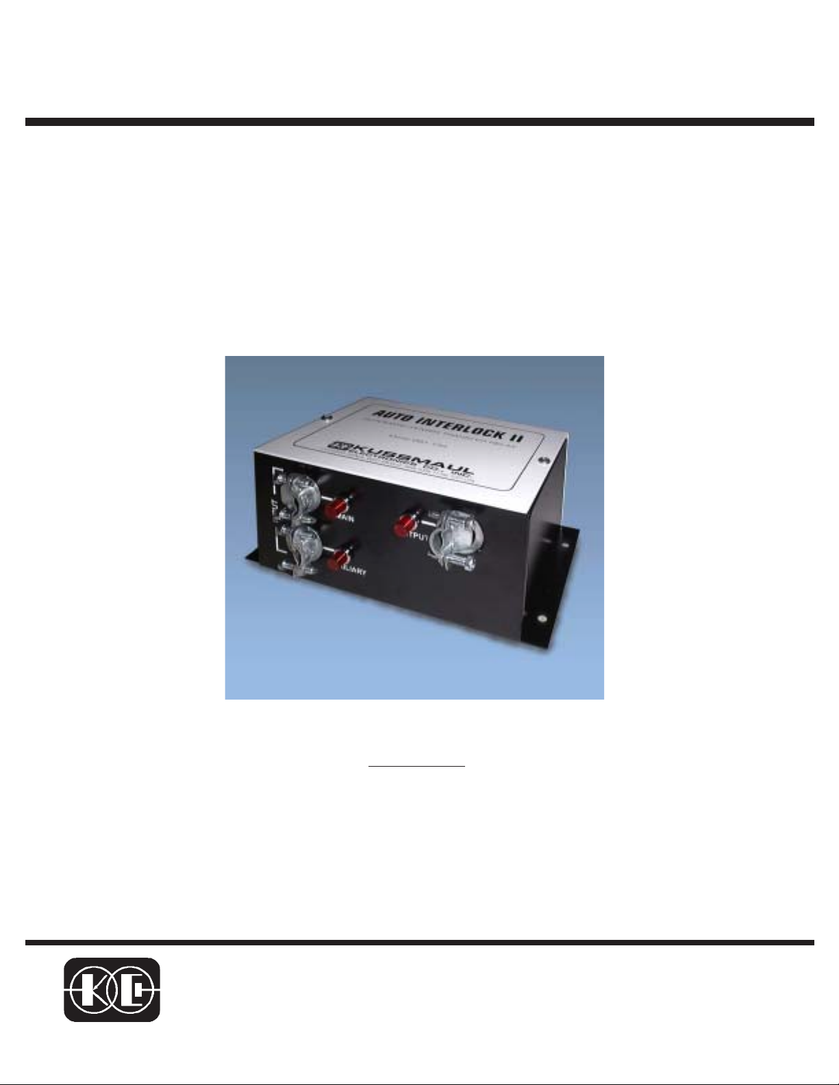
AUTO INTERLOCK IIA
AUTOMATIC TRANSFER AND
BATTERY CHARGER CIRCUIT
ISOLATION SWITCH
MODEL
091-134-025
3 YEAR WARRANTY
KUSSMAUL ELECTRONICS CO., INC.
170 CHERRY AVE., WEST SAYVILLE, N.Y. 11796-1221
TEL: in NY 631-567-0314 TOLL FREE: 800-346-0857 FAX: 631-567-5826
Page 2

INTRODUCTION:
The Model 091-134-025 AUT O INTERLOCK IIA is an automatic power transf er relay specifically
designed to isolate various battery charging systems such that
actively charging a battery at any time. Referring to Figure 1 the Model 091-134-025 AUTO
INTERLOCK IIA can accomodate three (3) battery charging system inputs and outputs as follows:
INPUTS
1. Conventional 115VAC High Powered or multi-step external battery charger (>10A) via
ShorePo wer 115VAC Input to High Po w er Charger.
2. 115VAC Generator equipped with DC output Alternator connected to common battery bank.
3. Low Power DC battery charger (<3A), i.e. Solar Panel, Float Voltage Charger.
OUTPUTS
1. 115VAC to conv entional high po wer charger.
2. Isolated DC battery charge circuit for Low Power Charger.
ONLY one (1) charging system is
THEORY OF OPERATION:
The Model 091-134-025 AUTO INTERLOCK IIA senses the Generator 115VAC output and the
status of a 115VAC connected “ShorePower” and configures the battery charging isolation as
follows.
! With neither ShorePower connected nor the Generator running the AUTO INTERLOCK IIA
connects the Low Power Charger (LPC) DC circuit to the battery.
! With ShorePo wer connected the A UT O INTERLOCK IIA tr ansf ers the f acility supplied power
to the AC input of a High Power Charger (HPC) and opens the DC circuit of the LPC to the
battery.
! With the Generator running the AU TO INTERLOCK IIA senses the gener ator 115V AC output
and disables the 115VAC ShorePow er input (whether present or not) to the HPC and opens
the DC circuit of the LPC to the battery.
The AUT O INTERLOCK IIA provides three (3) indicators f or “State Indication” in accordance with
the following T ab le
Battery Charging Circuit State and Indication Table
Generator Shorepower Battery Charge Circuit State Indication
OFF OFF LP C ALL OFF
OFF ON H P C Main & Output=ON, A uxiliary=OFF
ON OFF Generator Auxiliary=ON, Main & Output=OFF
ON ON Generator Main & Auxiliary=ON, Output=OFF
Page 3

A
of
1
1
11Tuesday, December 02, 2003
115VAC TO HPC
FIGURE 1, IM_091-134-025
2
NEMA 5-15 P/R
AC INPT+12VDC OUT
LOW POWER CHARGER + INPUT
KUSSMAUL AUTO ISOLATOR IIA
091-134-025
LOW POWER CHARGER + OUTPUT
GEN AC SENSE IN
SHORE PWR AC IN
AUTO ISOLATOR IIA
KUSSMAUL ELECTRONIC CO. WEST SAYVILLE, NY
Title
Size Document Number Rev
2
A
Date: Sheet
AC LOADS
3
3
-
* HIGH POWER CHARGER
+
4
* 12VDC BATTERY
* TRANSFER
SWITCH
4
-
+
+
ALTERNATOR
5
* LOW POWER
CHARGER
D D
* GENERATOR
M
AC GEN
115VAC SHOREPOWER
C C
B B
* CUSTOMER SUPPLIED
A A
5
Page 4

INST ALLATION:
Refer to Figure 2 for a typical installtion of the Model 091-134-025 AUTO INTERLOCK IIA.
Page 5

-025
A
Page 6

INSTALLATION RECORD & WARRANTY
Date Installed
Installed By
Vehicle Identification
Vehicle Owner
WARRANTY
All products of Kussmaul Electronics Company Inc. are warranted to be
free of defects of material or workmanship. Liability is limited to repairing or
replacing at our factory, without charge, any material or defects which become apparent in normal use within 3 years from the date the equipment
was shipped. Equipment is to be returned, shipping charges prepaid and will
be returned, after repair, shipping charges paid.
Kussmaul Electronics Company, Inc. shall have no liability f or damages
of any kind to associated equipment arising from the installation and /or use
of the Kussmaul Electronics Company, Inc. products. The purchaser , b y the
acceptance of the equipment, assumes all liability for any damages which
may result from its installation, use or misuse, by the purchaser, his or its
employ ees or others.
 Loading...