

Page 1
BOOK# 091-12DV-HO
INSTRUCTION MANUAL
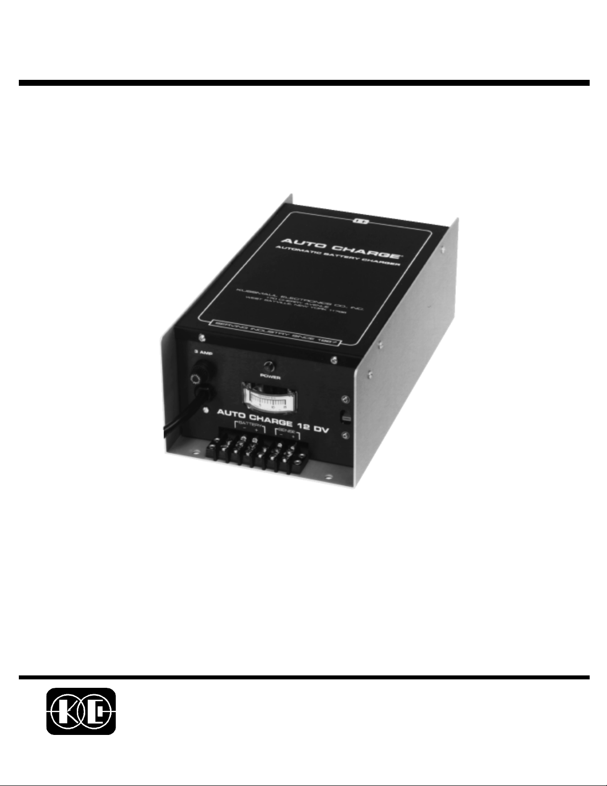
AUTO CHARGE 12HO DV
AUTOMATIC BATTERY CHARGER
MODEL #091-12HO DV
NOTE :
This charger is designed for
vehicles with a single
battery system
INPUT :120/230 volt, 50/60 Hz
3 YEAR WARRANTY
KUSSMAUL ELECTRONICS CO., INC.
170 CHERRY AVE., WEST SAYVILLE, N.Y. 11796-1221
TEL: in NY 631-567-0314 TOLL FREE: 800-346-0857 FAX: 631-567-5826
Page 2

1.0 INTRODUCTION
This manual describes the installation and wiring for the Auto-Charge 12HO DV Automatic
Battery Charger. It is suggested that the installer read the entire instructions to become familiar with the tasks involved before starting.
2.0 VEHICLE WIRING INSTALLATION
The installation of the vehicle wiring provides a direct connection between the battery and the
Auto-Charge 12HO DV Automatic Battery Charger. The battery is automatically charged at
constant voltage. For deeply discharged batteries or if the charger is operated while
thevehicle is started, a current limiter automatically limits the output to 20 amperes. Input
power may be either 115 volts or 230 volts, 50 or 60 Herz. A recessed voltage selector switch
is provided on the end panel near the output terminal strip.
The Auto-Charge 12HO DV uses remote sensing and therefore four wires are necessary to
connect to the battery. Two wires charge the battery while an additional two wires detect the
battery voltage. These connections are made on the output terminal strip.
3. AUTO-CHARGE 12HO DV INSTALLATION
The Auto-Charge 12HO DV Automatic Battery Charger should be installed in an area with
adequate ventilation. A power cord is supplied for connection to the input power source. A
switch on the end panel of the charger selects either 115 volts or 230 volts. Set this switch to
the proper position to correspond to the input voltage before applying power to the charger.
1. Mount the charger using the four holes provided. See figure 1.
2. Connect the wiring from the batteries to the Output Terminal Strip. Spade lugs that have
been securely crimped or soldered should be used
3. Connect the wiring to the batteries. Ring lugs that have been securely crimped or sol
dered should be used.
4. Double check all wiring before proceeding.
5. Wire the A.C. power line to the power source and check the position of the Voltage Selec
tor Switch.
NOTE
DO NOT APPLY 230 VOLTS TO THE CHARGER WITH THE SELECTOR
SWITCH IN THE 115 VOLT POSITION SERIOUS DAMAGE MAY RESULT
6. The pilot light will light to show that the charger has power.
7. The ammeter will indicate how much current is flowing to the battery. A charging current
limit of 20 amperes is factory set.
Page 3

4.0 SPECIFICATIONS
Input: 230 volts/115 volts, 50/60 Hz, switch selectable
Output Volts: Adjustable, 13.25 volts nominal
Output Current: 0 - 20 Amps, D.C., Current Limited
Charge Indicator: 0 - 25 Amps.
Weight: 13 pounds
Size: 12.75 x 6.73 x 4.25 inches
SPARE PARTS LIST
PART NUMBER DESCRIPTION
B091-349 Assembly, Control Board
3596 Transformer,Power
SPW405-S Transformer,Power,PC mount
B-511-2 Rectifier Bridge
A091-15-017 Sense Resistor Assembly
EM 5822 Meter, 0-25 Amp D.C.
2150-A1 Light,Indicator,Neon
LM3900 Integ.Circuit, Quad Op Amp
IP15WB-1K Potentiometer,trimming,1K
LM7812 Integ.Circuit, Volt Reg
2N4401 Transistor, NPN
1N4004 Diode, Rectifier
1N914 Diode, Signal
1N751 Diode, 5.1V Zener
779 Line Cord
11Z2101 Transformer, Trigger
V802 210.51/250 Switch, Voltage Select
Page 4

INSTALLATION WIRING DIAGRAM
WIRE SIZE CHART
CONNECTION ITEM DEFINITION WIRE
BAT-
BAT+
SENSE
_
SENSE
+
BATTERY
NEGATIVE
BATTERY
POSITIVE
NEGATIVE
SENSE
POSITIVE
SENSE
NEGATIVE CHARGING LEAD
FOR BATTERIES
POSITIVE CHARGING LEAD
FOR BATTERY # 1
NEGATIVE VOLTAGE SENSE
LEAD. DETECTS VOLTAGE
POSITIVE VOLTAGE SENSE
LEAD. DETECTS VOLTAGE
SIZE
12
AWG
12
AWG
16
AWG
16
AWG
IMPORTANT: Wire size is for a
maximum length of 20 feet. If wiring
is to be longer, larger wiring is required. Additional information is
available on request.
NOTE: The sense leads must be
connected to the battery for the
charger to operate.
NOTE: Sense leads are shown
connected to battery. For installations that do no permit a 4 wire
connection the positive sense
terminal may be connected to the
“Battery +” terminal and the negative sense terminal may be connected to the “Battery -” terminal.
This eliminates the remote sensing feature.
Page 5

SPECIFICATION & OUTLINE
SPECIFICATIONS:
Input: 115/230V 50/60Hz, 4 amps
Output: see chart
Output Current: see chart
Charge Indicator: 0-25 amps 5%
Weight: 22 lbs
6.75
SPECIFICATION CHART
MODEL # AMPS VOLTAGE
091-12HO-DV-6 20 6
091-12HO-DV-1 2 20 12
091-11HO-DV-2 4 12 24
091-12HO-DV-3 2 10 32
091-12HO-DV-3 6 8 36
091-12HO-DV-4 8 6 48
12.00
AUTO CHARGE
12.75
4.75
9/32" DIA. 4 HOLES
4.25
OUTLINE DRAWING
Page 6

INSTALLATION RECORD & WARRANTY
Date Installed
Installed By
Vehicle Identification
Vehicle Owner
WARRANTY
All product of Kussmaul Electronics Company Inc. are warranted to be
free of defects of material or workmanship. Liability is limited to repairing
or replacing at our factory, without charge, any material or defects which
become apparent in normal use within 3 years from the date the equipment was shipped.
Kussmaul Electronics Company, Inc. shall have no liability for damages of
any kind to associated equipment arising from the installation and /or use
of the Kussmaul Electronics Company, Inc. products. The purchaser, by
the acceptance of the equipment, assumes all liability for any damages
which may result from its installation, use or misuse, by the purchaser, his
or its
 Loading...