

Page 1
®
®
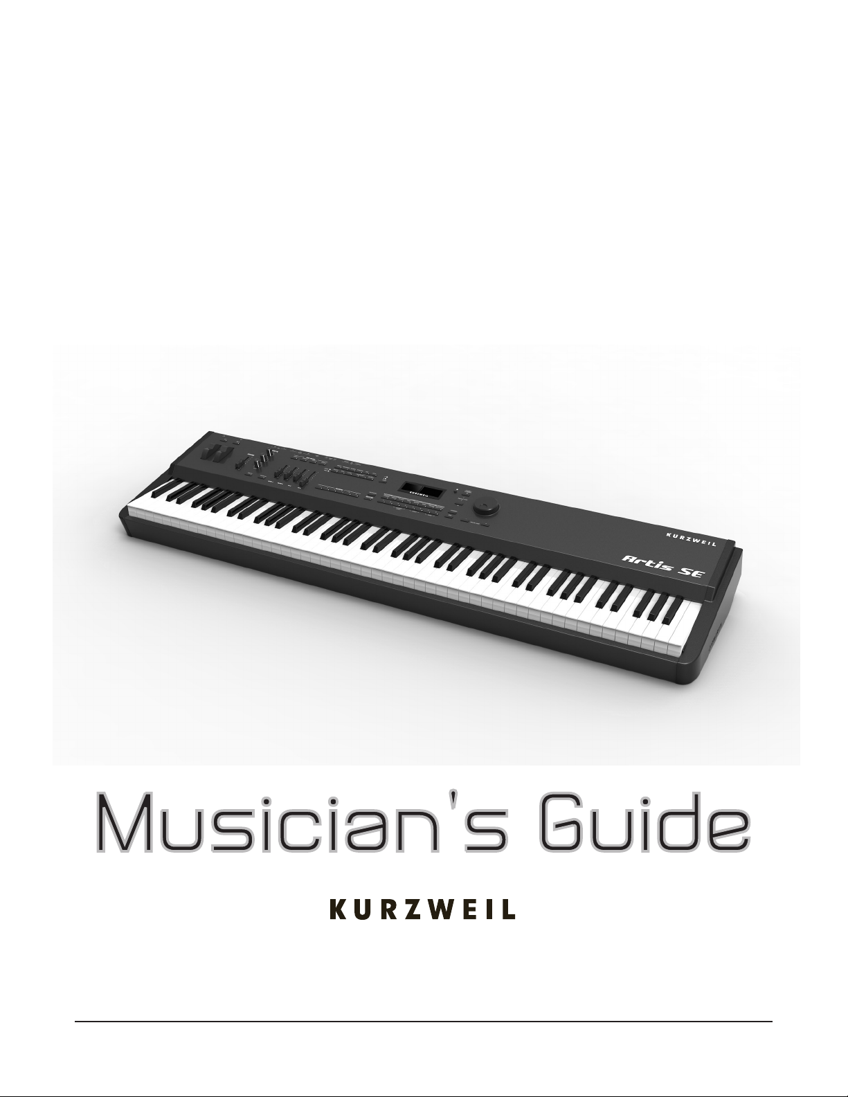
Artis SE
STAGE PIANO
Part Number 910570-001
i
Page 2

CAUTION
RISK OF ELECTRIC SHOCK
DO NOT OPEN
The lightning flash with the arrowhead symbol, within an equilateral
triangle is intended to alert the user to the presence of uninsulated
"dangerous voltage" within the product's enclosure that may be of
sufficient magnitude to constitute a risk of electric shock to persons.
CAUTION: TO REDUCE THE RISK OF ELECTRIC SHOCK,
REFER SERVICING TO QUALIFIED SERVICE PERSONNEL.
DO NOT REMOVE THE COVER.
NO USER SERVICEABLE PARTS INSIDE.
The exclamation point within an equilateral triangle is intended
to alert the user to the presence of important operating and
maintenance (servicing) instructions in the literature
accompanying the product.
IMPORTANT SAFETY & INSTALLATION INSTRUCTIONS
INSTRUCTIONS PERTAINING TO THE RISK OF FIRE ELECTRIC SHOCK , OR INJURY TO PERSONS
WARNING: When using electric products, basic precautions should
always be followed, including the following:
1. Read all the Safety and Installation Instructions and Explanation
of Graphic Symbols before using the product.
2. This product must be grounded. If it should malfunction or
break down, grounding provides a path of least resistance for
electric current to reduce the risk of electric shock. This product
is equipped with a power supply cord having an equipmentgrounding conductor and a grounding plug. The plug must be
plugged into an appropriate outlet which is properly installed and
grounded in accordance with all local codes and ordinances.
DANGER: Improper connection of the equipment-grounding
conductor can result in a risk of electric shock. Do not modify the
plug provided with the product – if it will not t the outlet, have a
proper outlet installed by a qualied electrician. Do not use an
adaptor which defeats the function of the equipment-grounding
conductor. If you are in doubt as to whether the product is properly
grounded, check with a qualied serviceman or electrician.
3. Do not use this product near water – for example, near a bathtub,
washbowl, kitchen sink, in a wet basement, or near a swimming
pool, or the like.
4. This product should only be used with a stand or cart that is
recommended by the manufacturer.
5. This product, either alone or in combination with an amplier and
speakers or headphones, may be capable of producing sound
levels that could cause permanent hearing loss. Do not operate
for a long period of time at a high volume level or a level that is
uncomfortable. If you experience any hearing loss or ringing in
the ears, you should consult an audiologist.
6. This product should be located so that its location or position
does not interfere with its proper ventilation.
7. The product should be located away from heat sources such as
radiators, heat registers, or other products that produce heat.
8. The product should be connected to a power supply only of the
type described in the operating instructions or as marked on the
product.
9. This product may be equipped with a polarized line plug (one
blade wider than the other). This is a safety feature. If you are
unable to insert the plug into the outlet, contact an electrician to
replace your obsolete outlet. Do not defeat the safety purpose of
the plug.
10. The power supply cord of the product should be unplugged
from the outlet when left unused for a long period of time. When
unplugging the power supply cord, do not pull on the cord, but
grasp it by the plug.
11. Care should be taken so that objects do not fall and liquids are
not spilled into the enclosure through openings.
12. The product should be serviced by qualied service personnel
when:
A. The power supply, power cord or plug have been damaged;
B. Objects have fallen, or liquid has been spilled into the
product;
C. The product has been exposed to rain;
D. The product does not appear to be operating normally or
exhibits a marked change in performance;
E. The product has been dropped, or the enclosure damaged.
13. Do not attempt to service the product beyond that described in
the user maintenance instructions. All other servicing should be
referred to qualied service personnel.
14. WARNING: Do not place objects on the product’s power supply
cord, or place the product in a position where anyone could trip
over, walk on, or roll anything over cords of any type. Do not
allow the product to rest on or be installed over cords of any type.
Improper installations of this type create the possibility of a re
hazard and/or personal injury.
RADIO AND TELEVISION INTERFERENCE
WARNING: Changes or modications to the instrument not expressly
approved by Young Chang could void your authority to operate the
instrument.
IMPORTANT: When connecting this product to accessories and/or
other equipment use only high quality shielded cables.
NOTE: This instrument has been tested and found to comply with the
limits for a Class B digital device, pursuant to Part 15 of the FCC Rules.
These limits are designed to provide reasonable protection against
harmful interference in a residential installation. This instrument
generates, uses, and can radiate radio frequency energy and, if not
installed and used in accordance with the instructions, may cause
harmful interference to radio communications. However, there is no
guarantee that interference will not occur in a particular installation. If
this instrument does cause harmful interference to radio or television
reception, which can be determined by turning the instrument off and
on, the user is encouraged to try to correct the interference by one or
more of the following measures:
• Reorient or relocate the receiving antenna.
SAVE THESE INSTRUCTIONS
ii
• Increase the separation between the instrument and the receiver.
• Connect the instrument into an outlet on a circuit other than the
one to which the receiver is connected.
• If necessary consult your dealer or an experienced radio/television
technician for additional suggestions.
The normal function of the product may be disturbed by strong
electromagnetic interference. If so, simply reset the product to resume
normal operation by following the instructions in the manual. If normal
function does not resume, please use the product in another location.
NOTICE
This apparatus does not exceed the Class B limits for radio noise
emissions from digital apparatus set out in the Radio Interference
Regulations of the Canadian Department of Communications.
AVIS
Le present appareil numerique n’emet pas de bruits radioelectriques
depassant les limites applicables aux appareils numeriques de la
class B prescrites dans le Reglement sur le brouillage radioelectrique
edicte par le ministere des Communications du Canada.
Page 3

IMPORTANT SAFETY INSTRUCTIONS
1) Read these instructions.
2) Keep these instructions.
3) Heed all warnings.
4) Follow all instructions.
5) Do not use this apparatus near water.
6) Clean only with dry cloth.
7) Do not block any of the ventilation openings. Install in accordance with the manufacturer’s instructions.
8) Do not install near any heat sources such as radiators, heat registers, stoves, or other apparatus (including
ampliers) that produce heat.
9) Do not defeat the safety purpose of the polarized or grounding-type plug. A polarized plug has two
blades with one wider than the other. A grounding type plug has two blades and a third grounding
prong. e wide blade or the third prong are provided for your safety. If the provided plug does not t
into your outlet, consult an electrician for replacement of the obsolete outlet
10) Protect the power cord and power supply adapter from being walked on or pinched, particularly at plugs,
convenience receptacles, and the point where they exit from the apparatus.
11) Only use power adapters andattachments/accessories specied by the manufacturer.
12) Use only with a cart, stand, tripod, bracket, or table specied by the manufacturer,
or sold with the apparatus. When a cart is used, use caution when moving the cart/
apparatus combination to avoid injury from tip-over.
13) Unplug this apparatus during lightning storms or when unused for long periods of
time.
14) Refer all servicing to qualied service personnel. Servicing is required when the apparatus has been
damaged in any way, such as power-supply cord or plug is damaged, liquid has been spilled or objects
have fallen into the apparatus, the apparatus has been exposed to rain or moisture, does not operate
normally, or has been dropped.
Warning: To reduce the risk of re or electric shock, do not expose this apparatus to rain or moisture. Do not
expose this equipment to dripping or splashing and ensure that no objects lled with liquids, such as vases, are
placed on the equipment.
To completely disconnect this equipment from the AC Mains, disconnect the power supply cord plug from
the AC receptacle.
©2014 Young Chang Co., Ltd. All rights reserved. Kurzweil® is a product line of Young Chang Co., Ltd. Kurzweil®, Young Chang®, V. A. S. T.®,
and Artis SE™ are trademarks of Young Chang Co., Ltd. All other trademarks and copyrights are property of their respective companies. Product
features and specications are subject to change without notice.
You may legally print up to two (2) copies of this document for personal use. Commercial use of any copies of this document is prohibited.
Young Chang Co. retains ownership of all intellectual property represented by this document.
iii
Page 4

Kurzweil International Contacts
Contact the Kurzweil oce listed below to locate your local Kurzweil representative.
US Customers:
American Music & Sound
22020 Clarendon Street, Suite 305
Woodland Hills, CA 91367
Tel: 800-431-2609
Fax: 818-597-0411
Email: info@americanmusicandsound.com
www.kurzweil.com
Customers outside the US:
Young Chang Co., LTD.
9th Floor, Bldg 102, I-Park,
Jeongja-Dong, Bundang-Gu, Seongnam-Si,
Gyeonggi-Do
463-859 South Korea
Tel: +82 31 786 7900
iv
support@kurzweil.com
www.facebook.com/kurzweilmusicsystems/
www.twitter.com/KurzweilMusic
www.youtube.com/user/KurzweilTutorials
Page 5

Contents
Kurzweil International Contacts ......................................................iv
Introducing Artis SE .................................. 1-1
Main Features ................................................................................ 1-1
Sound sources .............................................................................. 1-2
Keyboard and Controllers ............................................................. 1-2
Pedals (Optional) .......................................................................... 1-2
Keeping the Artis SE up to date ................................................... 1-3
Do You Have Everything? ............................................................. 1-3
Music Rack (Optional) ................................................................... 1-3
Getting Started ........................................... 2-1
Contents
Before You Start… ......................................................................... 2-1
Quick Start ..................................................................................... 2-1
Using Artis SE ............................................................................... 2-2
Start Up Details: The Rear Panel................................................. 2-3
The DC Power Adapter ................................................................. 2-3
The USB Ports .............................................................................. 2-3
The MIDI (IN and OUT) Ports ....................................................... 2-4
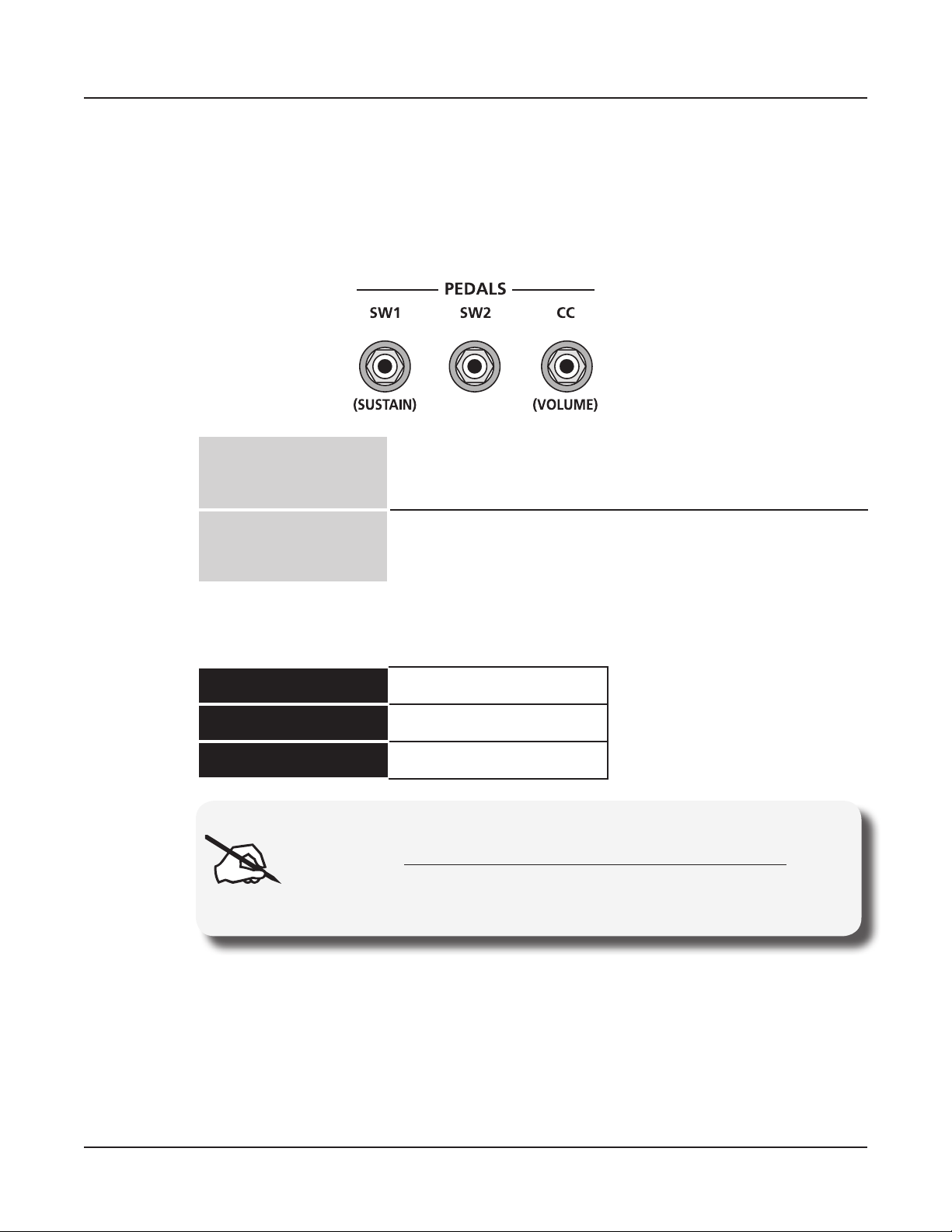
The Pedal Jacks............................................................................ 2-4
The SW1 (Sustain) and SW2 Jacks ........................................... 2-4
The CC Jack ............................................................................... 2-4
The Headphones Jack .................................................................. 2-5
The Audio In Jack.......................................................................... 2-5
Connecting the Power Adapter .................................................... 2-5
Connecting to Your Audio System ............................................... 2-5
The Audio Out Jacks (Right and Left/Mono) ................................. 2-5
Connecting Pedals ........................................................................ 2-7
Connecting a Single Switch Pedal ................................................ 2-7
Connecting a Dual Switch Pedal ................................................... 2-8
Connecting a Half Damper Pedal.................................................. 2-9
Connecting a Continuous Control Pedal ..................................... 2-10
Connecting MIDI .......................................................................... 2-11
Basic MIDI Hookup ......................................................................2-11
Connecting More Sound Modules ................................................2-11
v
Page 6

Contents
Connecting to a Computer Sequencer ........................................ 2-12
Selecting Programs and Multis .................................................. 2-13
Features of the Artis SE ............................ 3-1
Powering Up Defaults ................................................................... 3-1
Parameters Reset To Defaults At Power-On ................................. 3-1
Parameters Remembered After Power-On ................................... 3-1
The Front Panel ............................................................................. 3-2
Real Time Controls ........................................................................ 3-3
Pitch Wheel ................................................................................... 3-3
Modulation Wheel ......................................................................... 3-3
Programmable Switches (SW1 and SW2) .................................... 3-3
Foot Switches and Controllers ...................................................... 3-4
Audio Level Controls .................................................................... 3-4
Volume Slider ................................................................................ 3-4
Audio In ......................................................................................... 3-4
Master EQ ..................................................................................... 3-4
Sliders and Filter-FX button .......................................................... 3-5
ZONE ON/OFF Buttons ................................................................ 3-6
Mode Buttons ................................................................................. 3-6
Multi Button ................................................................................... 3-7
Program Button ............................................................................. 3-7
Global Button ................................................................................ 3-7
Storage Button .............................................................................. 3-7
Edit Button (Multi Edit Mode) ........................................................ 3-7
Save Button................................................................................... 3-8
Function Buttons ........................................................................... 3-8
Sound ............................................................................................ 3-8
Split ............................................................................................... 3-8
Layer ............................................................................................. 3-9
Transpose -/+ and Octave ............................................................. 3-9
Favorites ....................................................................................... 3-10
Category and sound selection ................................................... 3-10
CATEGORY button ..................................................................... 3-10
USER button ............................................................................... 3-10
A/B Bank button ...........................................................................3-11
Navigation .................................................................................... 3-11
The LCD Display ..........................................................................3-11
(–) and (+) Value Buttons ............................................................ 3-12
Param / Channel Buttons ............................................................ 3-12
Alpha Wheel ................................................................................ 3-12
ASSIGN and EXIT Buttons ......................................................... 3-12
vi
Page 7

Double Button Presses ............................................................... 3-13
Value Jump ................................................................................. 3-13
Parameter Jump .......................................................................... 3-13
Reset Transposition .................................................................... 3-13
Program Demo ............................................................................ 3-14
Demo ........................................................................................... 3-14
Panic ........................................................................................... 3-14
Assign ......................................................................................... 3-14
Assign + Zone (1–4) Button ...................................................... 3-14
Assign + Controller ................................................................... 3-15
Assign + Keyboard key ............................................................. 3-15
Terminology ................................................ 4-1
The Operating Modes ................................ 5-1
Multi Mode ...................................................................................... 5-1
Program Mode ............................................................................... 5-2
Contents
Global Mode ................................................................................... 5-2
Storage Mode ................................................................................. 5-2
Multi Edit Mode .............................................................................. 5-2
Functions ....................................................................................... 5-3
The Sound Function ...................................................................... 5-3
The Split Function ......................................................................... 5-3
The Layer Function ....................................................................... 5-3
Transpose Functions ..................................................................... 5-3
Program and Song Demo Functions ............................................. 5-3
Program Mode ............................................ 6-1
About Program Mode .................................................................... 6-1
Selecting Programs ....................................................................... 6-1
Program Demo .............................................................................. 6-2
The Display ................................................................................... 6-2
Pop Up Messages ...................................................................... 6-2
Alpha Wheel & – and + Value Buttons .......................................... 6-3
Value Jump Buttons ...................................................................... 6-3
Category & Program/Multi Buttons................................................ 6-4
Choosing Category Default Programs .......................................... 6-5
Choosing Favorites ....................................................................... 6-5
Transposition ................................................................................. 6-5
Parameter Assignments ............................................................... 6-6
The Split Function ......................................................................... 6-6
Split Key ...................................................................................... 6-8
vii
Page 8

Contents
Split Transpose ........................................................................... 6-8
Saving a Split ................................................................................ 6-8
The Layer Function ....................................................................... 6-8
Layer Volume .............................................................................. 6-9
Layer Transpose ....................................................................... 6-10
Saving a Layer ............................................................................ 6-10
Changing the Transmit MIDI Channel ........................................ 6-10
Panic ............................................................................................. 6-11
Saving User Programs ................................................................ 6-11
Changing ID Numbers................................................................. 6-12
Naming a User Program ............................................................. 6-12
Locating a saved User Program.................................................. 6-12
Multi Mode .................................................. 7-1
About Multi Mode .......................................................................... 7-1
About Zones ................................................................................... 7-1
Selecting Multis ............................................................................. 7-2
The Display ................................................................................... 7-2
Alpha Wheel and – & + Value Buttons ...................................... 7-3
Value Jump Buttons ...................................................................... 7-3
Category & Program/Multi Buttons................................................ 7-3
Choosing Category Default Multis................................................. 7-4
Choosing Favorites ....................................................................... 7-4
Transposition ................................................................................. 7-4
The Split Function ......................................................................... 7-5
Split Program .............................................................................. 7-5
Split Volume ................................................................................ 7-6
Split Key ...................................................................................... 7-6
Saving a Split ................................................................................ 7-6
The Layer Function ....................................................................... 7-6
Layer Program ........................................................................... 7-7
Layer Volume .............................................................................. 7-7
Layer Transpose ......................................................................... 7-7
Saving a Layer .............................................................................. 7-8
Saving User Multis ........................................................................ 7-8
Changing ID Numbers................................................................... 7-8
Naming a User Multi ...................................................................... 7-9
Completing a User Multi Save....................................................... 7-9
viii
Page 9

Multi Edit Mode ........................................... 8-1
About Multi Edit Mode .................................................................. 8-1
The Parameters List ...................................................................... 8-2
Selecting Parameters .................................................................... 8-4
The Display ................................................................................... 8-4
Scrolling Messages..................................................................... 8-4
Param/Channel Buttons ................................................................ 8-4
Alpha Wheel and Value buttons .................................................... 8-4
Value Jump Buttons ...................................................................... 8-4
Param Jump Buttons..................................................................... 8-4
Assign ........................................................................................... 8-5
Assign + Zone (1–4) Button ........................................................ 8-5
Assign + controller ...................................................................... 8-5
Assign + key ............................................................................... 8-5
The Zone-specic Parameters ..................................................... 8-5
Local Program (Local Prog) .......................................................... 8-5
Channel ......................................................................................... 8-6
Destination (Dest) ......................................................................... 8-6
Zone Status (Status) ..................................................................... 8-6
Entry Volume (EntryVol) ................................................................ 8-6
Entry Pan ...................................................................................... 8-7
Aux Send Level (AuxSendLvl) ...................................................... 8-7
Zone Channel Effects (ZnChanFX) ............................................... 8-7
Transpose (Xpose) ........................................................................ 8-7
Low Key (LoKey) ........................................................................... 8-7
High Key (HiKey) ........................................................................... 8-7
Low Velocity (LoVel) ...................................................................... 8-8
High Velocity (HiVel)...................................................................... 8-8
Notemap ........................................................................................ 8-8
MIDI Bank ..................................................................................... 8-8
MIDI Program ................................................................................ 8-9
Entry Program Change (EntryPrgChg) ....................................... 8-10
Bank Mode .................................................................................. 8-10
Bend Range Down (BendRngDwn) ............................................ 8-10
Bend Range Up (BendRngUp).................................................... 8-10
Continuous Controller Parameters ...............................................8-11
Destination (Dest) ......................................................................8-11
Controlling Program Parameter Assignments from Multi Mode 8-13
Entry Value ............................................................................... 8-13
Exit Value .................................................................................. 8-13
The Pedal Switch & Switch Button Parameters .......................... 8-13
Mode ......................................................................................... 8-14
Destination (Dest) ..................................................................... 8-14
Contents
ix
Page 10

Contents
On Value (OnVal) ...................................................................... 8-14
Off Value (OffVal) ...................................................................... 8-14
Entry State ................................................................................ 8-14
Exit State .................................................................................. 8-14
About Auxiliary Effects ............................................................... 8-15
Common Parameters .................................................................. 8-15
Aux FX ........................................................................................ 8-15
Aux FX Channel (AuxFXCh) ....................................................... 8-15
KB3 Channel ............................................................................... 8-16
Tempo ......................................................................................... 8-16
Saving User Multis ...................................................................... 8-16
Global Mode ................................................ 9-1
Selecting and Editing Parameters ............................................... 9-2
The Global Parameters ................................................................. 9-3
Tune .............................................................................................. 9-3
Velocity Map .................................................................................. 9-3
FX Select (FXSel) ......................................................................... 9-4
Auto Power Off ............................................................................. 9-4
Auto Power Off Time ..................................................................... 9-4
Pedal Noise ................................................................................... 9-4
Hard Reset? .................................................................................. 9-5
Soft Reset? ................................................................................... 9-5
Bank Select (BankSel) .................................................................. 9-6
Program Change (ProgChg) ......................................................... 9-6
Channel Enable............................................................................. 9-6
Local Keyboard Channel (LclKbdChan) ........................................ 9-6
Program Mode ............................................................................ 9-7
Multi Mode .................................................................................. 9-7
Sysex ID ........................................................................................ 9-7
Objects/OS .................................................................................... 9-7
Delete Objects?............................................................................. 9-8
Storage Mode ........................................... 10-1
Device ......................................................................................... 10-1
Store? ......................................................................................... 10-2
Load (Overwrite)? ...................................................................... 10-3
Load (Fill)? ................................................................................. 10-4
x
Page 11

System Mode (Boot Loader) ................... 11-1
System Mode Buttons ................................................................. 11-2
Run Artis SE ................................................................................. 11-2
Update Software .......................................................................... 11-2
Update..........................................................................................11-2
Restore .........................................................................................11-3
Run Diagnostics .......................................................................... 11-4
System Reset ............................................................................... 11-4
File Utilities .................................................................................. 11-4
Troubleshooting ....................................... 12-1
Maintenance ................................................................................. 12-1
Common Problems ...................................................................... 12-1
Power Problems .......................................................................... 12-1
Powers up, Display is Blank ........................................................ 12-2
Audio Problems ........................................................................... 12-2
Contents
MIDI Problems .............................................................................. 12-4
Pedal Problems............................................................................ 12-5
Switch Pedal Problems ............................................................... 12-5
Continuous Control and Half Damper Pedal Problems ............... 12-5
If None of the Above... ................................................................. 12-6
Restoring Factory Defaults.......................................................... 12-6
Diagnostics .................................................................................. 12-7
MIDI Implementation ..................................A-1
Physical Specications .............................B-1
Factory Programs ......................................C-1
Factory Multis ............................................. D-1
Index ............................................................. I-1
xi
Page 12
Chapter 1
Introducing Artis SE
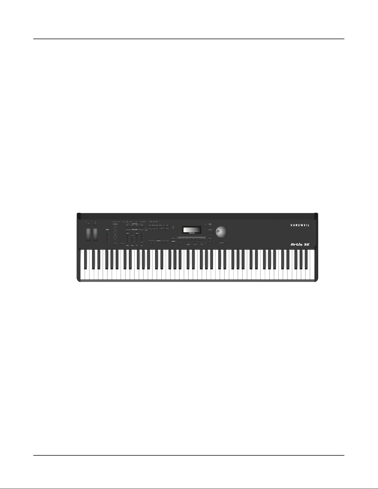
Congratulations on your purchase of the Kurzweil Artis SE® Stage Piano!
is manual will help you get acquainted with your new instrument. Be sure to keep the
manual on hand as you continue to familiarize yourself with the features and functions of the
Artis SE.
Introducing Artis SE
Main Features
Main Features
e Artis SE Stage Piano is the beginning of the next generation of Kurzweil’s professional
performance instruments. It boasts hundreds of excellent preset sounds (including the new
German D Grand EXP set of piano sounds and the Enhanced Kore64 ROM) already onboard and ready to be played with 128 voice polyphony.
e Artis SE is also a very capable MIDI controller ideally suited for controlling additional
sound modules and as input to a sequencer.
1-1
Page 13

Introducing Artis SE
Main Features
Sound sources
• 256 Factory Programs divided into 16 Categories
• 256 User IDs to save your own Programs
• 128 Factory Multis and 256 User IDs to save your own Multis
• MP3 player audio input jack
• Full 128 voices of polyphony
• KB3 organ simulations with 4 sliders as drawbars
Keyboard and Controllers
e Artis SE has an 88-key fully-weighted hammer action keyboard that provides you with
a piano-like feel without adding excessive weight to the instrument. e array of physical
controllers includes:
• 4 assignable sliders, with shift function to control 8 parameters
• 2 programmable switches
• Pitch and Modulation wheels
• MIDI In and Out jacks
• 2 USB ports for MIDI and le transfers
• 2 jacks for optional switch pedals
• 1 jack for an optional continuous controller pedal
Pedals (Optional)
As described above, the Artis SE has three jacks on the rear panel for optional pedal
controllers. Two jacks for switch pedals, which are typically used to control two-state (i.e.,
on / o) parameters such as sustain, sostenuto, and mute Zone. e third jack is for a
continuous control (or CC) pedal typically used to control multi-state (i.e., “continuous”)
parameters such as volume or wah.
Your Kurzweil dealer stocks the following pedals:
• FS-1 Standard box-shaped switch pedal
• KFP-1 Single piano-style switch pedal
• KFP-2S Double piano-style switch pedal unit (one stereo plug)
• CC-1 Continuous pedal
1-2
Page 14
Keeping the Artis SE up to date
Be sure to check the Kurzweil Music Systems website at http://www.kurzweil.com for new
documentation and the latest software updates for Artis SE.
Do You Have Everything?
Your Artis SE package should contain the following in addition to your instrument:
• Power adapter and cable
• Switch pedal
• USB cable (Type-A-to-Type-B)
• 4 self adhesive feet (see page 2-1)
• Artis SE Getting Started Guide
If you are missing any of these components, please contact your Kurzweil / Young Chang
dealer to get them.
Introducing Artis SE
Keeping the Artis SE up to date
Music Rack (Optional)
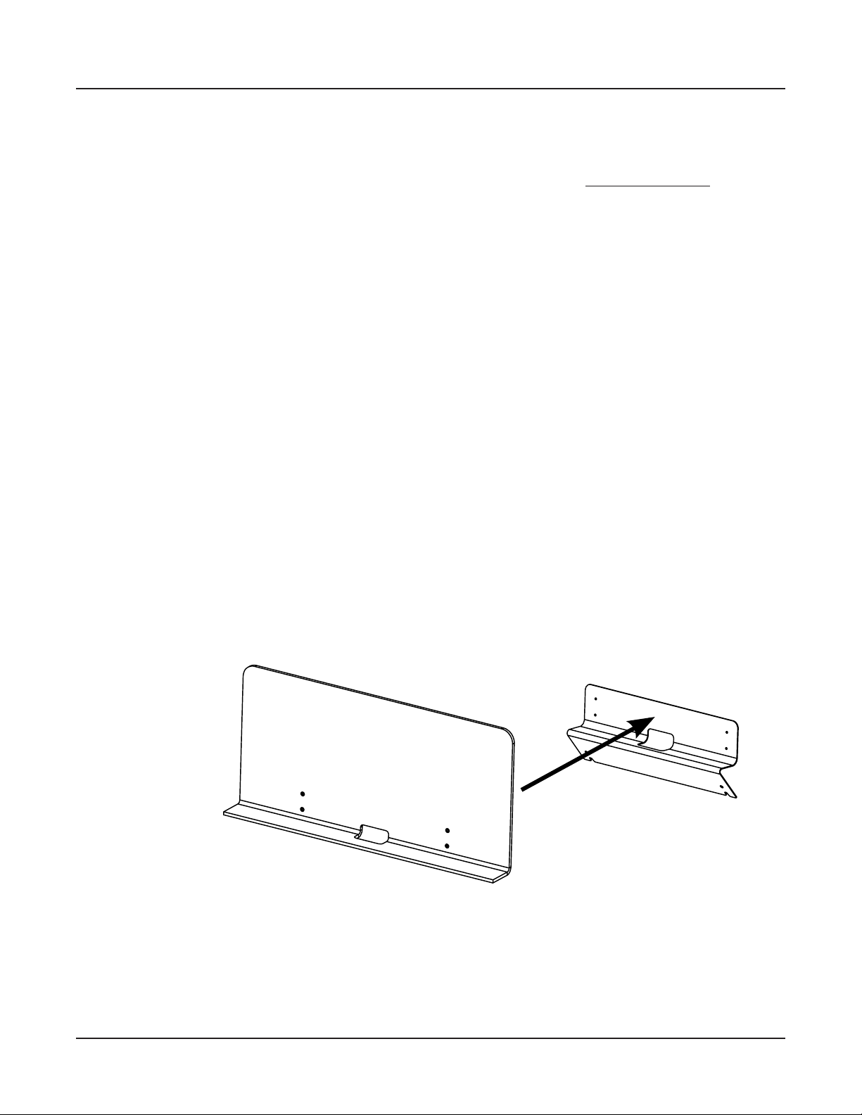
e optional KMR2 Music Rack attachment is a holder for sheet music or a computer tablet
device. Contact your Kurzweil dealer for the KMR2 Music Rack.
Please refer to the instructions that come with the KMR2 on attaching the music rack to the
Artis SE.
1-3
Page 15
Chapter 2
Getting Started
Getting a new keyboard is always exciting and the rst thing most users want to do is unpack
the keyboard and check things out. is chapter will help you hook up the Artis SE to your
sound system and MIDI system, give you a quick overview, and show you how to get some
sound out of the Artis SE.
Getting Started
Before You Start…
Before You Start…
Don’t connect anything until you make sure the Artis SE is properly and safely situated.
If your Artis SE keyboard has been out in the cold, give it time to warm up to room
temperature before starting it, since condensation may have formed inside.
Quick Start
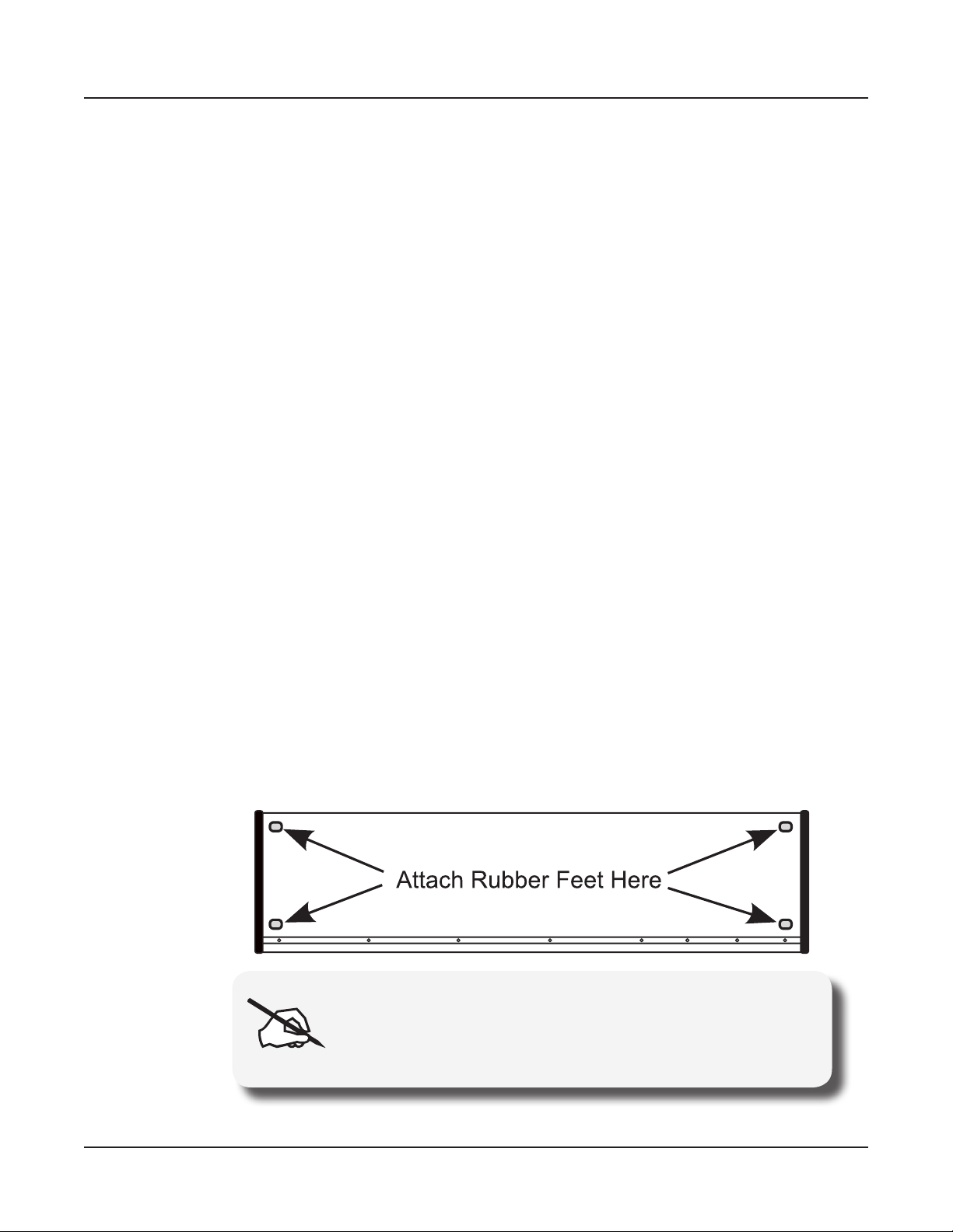
1. Set the keyboard on a hard, at, level surface.
2. Four adhesive-backed rubber feet are provided with Artis SE. Carefully turn the keyboard
over onto a soft surface, remove the paper backing from the rubber feet and attach them.
NOTE : Unless the instrument will always be used with a
keyboard stand, attachment of the rubber feet is strongly
advised. Otherwise protruding screws will scratch the tabletop
and may increase the key action sound.
2-1
Page 16
Getting Started
Quick Start
3. Connect the AC power adapter to the Artis SE. Before plugging the power adapter’s
4. Plug the power cable into the wall.
5. Plug the Switch Pedal into the marked SW1 (Sustain) Pedal jack on the Artis SE rear
6. Connect stereo headphones to the headphone jack on the rear left panel, or connect the
7. Make sure your sound system is at a safe volume level. Also make sure that the Artis SE
cable into a power outlet, check that the power outlet is compatible with the Artis SE.
e Artis SE runs on AC power and works with voltages from 90 - 260 volts at 50–60
Hz. e voltage level is detected and set automatically by the power supply. If your power
outlet is not within these ranges it is recommended you use an appropriate adapter.
panel.
audio outputs to your mixer or amplier inputs using standard (1/4-inch) audio cables
(use the Left out for mono). Balanced (“TRS” or “Stereo”) cables are recommended if
your mixer or amp supports balanced inputs.
MASTER VOLUME slider (on the far left side of the front panel) is all the way down.
Using Artis SE
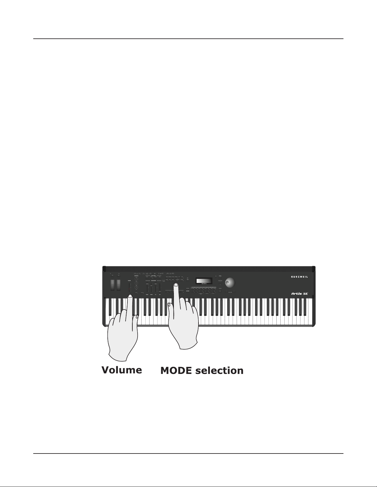
1. Power up the Artis SE, and then raise the MASTER VOLUME slider, and mixer/amp
volume. Your Artis SE keyboard starts up in Multi Mode by default. Press one of the
buttons under the “Mode” label to the right of the display to switch Modes.
2-2
2. If you are connected to a mixing board and hear distortion, reduce the gain level on your
mixing board, or use the pad (a switch that decreases the input audio signal level, typically
by 20dB) if it has one.
3. Scroll through the Programs using the Alpha Wheel, the Previous and Next buttons, or
press a Category button to audition the sounds in Artis SE.
Page 17
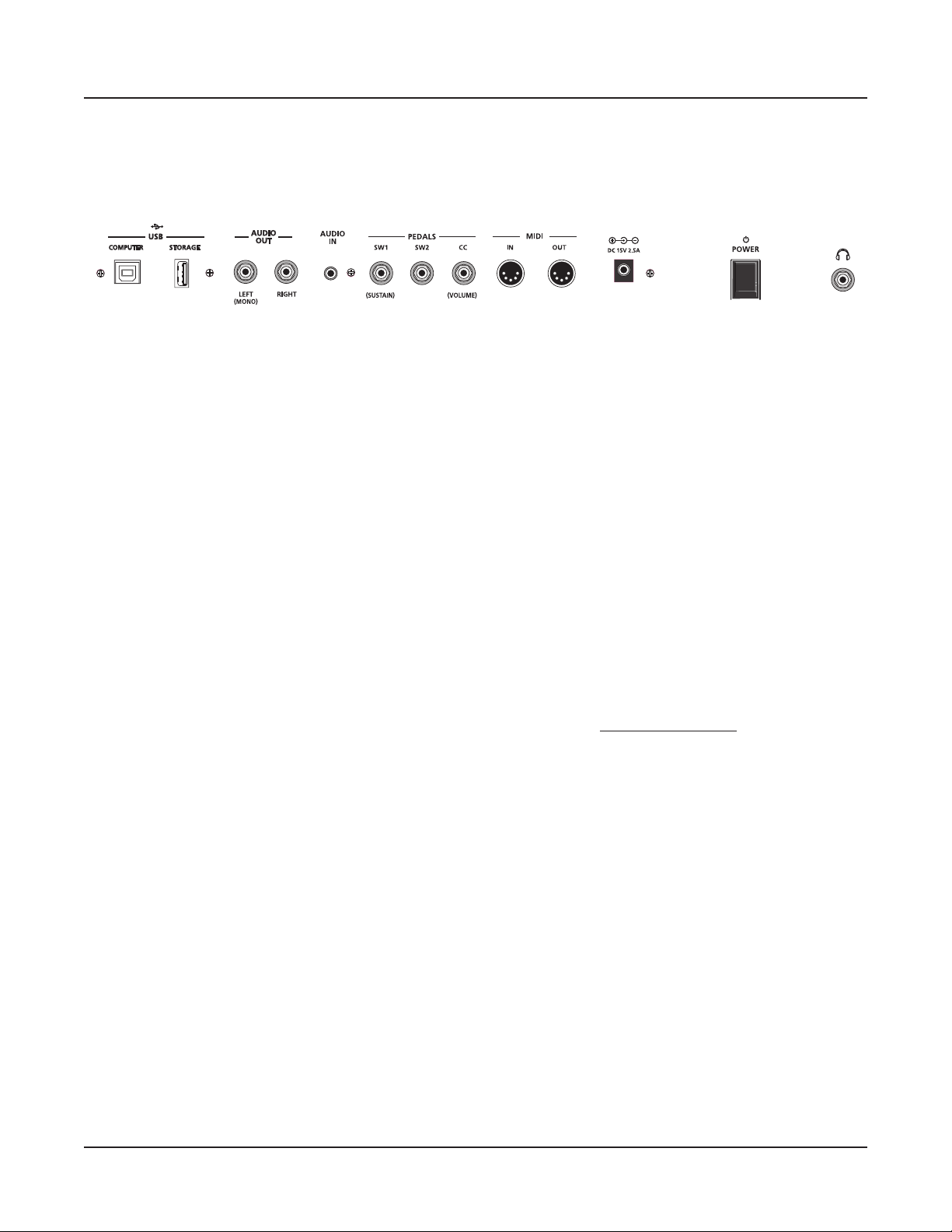
Start Up Details: The Rear Panel
e power switch and Artis SE connections are located on the rear panel.
The DC Power Adapter
Use the provided DC power adapter to connect the Artis SE to a standard AC power source.
The USB Ports
Getting Started
Start Up Details: The Rear Panel
Use the USB ports to connect the Artis SE to a computer/tablet in order to do the following:
• Use the Artis SE as a MIDI controller to play software instruments on a computer.
• Use a computer program to sequence multitrack songs on the Artis SE.
• Use a computer/tablet to manage the user data contents of the Artis SE.
• Update the software and sounds of the Artis SE.
• Store custom Programs and Multis on a USB ash drive.
Be sure to check the Kurzweil Music Systems website at www.kurzweil.com for new
documentation and software updates before using your new instrument.
2-3
Page 18
Getting Started
Start Up Details: The Rear Panel
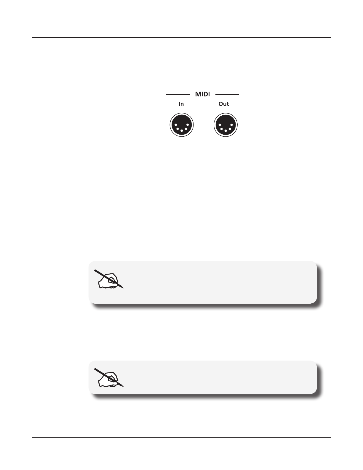
The MIDI (IN and OUT) Ports
Use the MIDI ports to communicate with other MIDI modules and controllers. e OUT
port is the MIDI transmitting port, and the IN port is the MIDI receiving port.
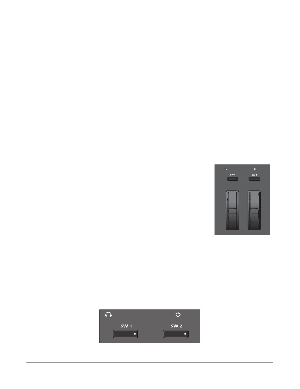
The Pedal Jacks
Use the three pedal jacks to connect controller pedals to Artis SE.
The SW1 (Sustain) and SW2 Jacks
Use the pedal jacks to connect switch pedals. A switch pedal is a physical controller typically
used to control two-state (i.e., “on / o”) parameters, such as sustain, sostenuto, and Mute
Zone.
It is possible to connect up to 2 dual switch pedals having a single stereo plug (Kurzweil
KFP-2S available separately) into the SW1 and SW2 jacks, (see Connecting a Dual Switch
Pedal on page 2-8) or up to 2 half damper pedals having stereo jacks.
NOTE : It is not recommended to plug CC pedals into the SW
inputs. Due to the exible switch pedal support, CC pedals
may not operate as expected in these inputs.
The CC Jack
Use the CC pedal jack to connect a continuous control (or CC) pedal. A CC pedal is a
physical controller typically used to control multi-state (i.e., “continuous”) parameters such
as volume or wah.
NOTE : Only CC pedals should be connected to the CC pedal
input.
2-4
For more information on connecting pedals, see page 2-6.
Page 19

The Headphones Jack
Use the HEADPHONES jack located on the rear/left of the instrument, behind the Pitch
and Modulation wheels, to listen to the Artis SE on stereo headphones. When headphones
are plugged in, sound still comes through the Left and Right audio jacks. You will need
a 1/4-inch-to-1/8-inch adapter in order to use headphones that have a smaller mini plug
connector.
The Audio In Jack
A ⅛” sized stereo audio jack labelled AUDIO IN on the back panel of the Artis SE allows
you to play an MP3 player or other audio source through the Artis SE. ere is no input
volume control for this on the Artis SE itself, so you should control the mix volume of the
Audio Input from the external audio player itself.
Connecting the Power Adapter
Getting Started
Connecting the Power Adapter
e Artis SE runs on standard AC power using a DC power adapter. With the rear panel
power switch in the O position, connect the DC power adapter to the Artis SE. A power
cord is included to connect the adapter to an AC outlet. Before plugging the cable into the
AC outlet, check that the power is compatible with the Artis SE (with voltages from 90 - 260
volts at 50–60 Hz).
Connecting to Your Audio System
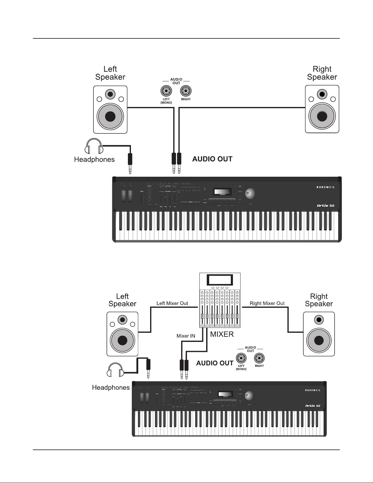
The Audio Out Jacks (Right and Left/Mono)
With the the level on your sound system turned down, connect the Artis SE analog audio
outputs to your sound system using a pair of balanced (TRS or “stereo”) or unbalanced
(TS or “mono”) audio cables. Unbalanced cables will always work, but if you’re going into
balanced inputs, use balanced cables for a better signal-to-noise ratio and a bit more volume.
e Artis SE analog outputs are balanced.
You’ll nd two 1/4-inch balanced audio output jacks on the rear panel. Connect one end of
each audio cable to your mixing board or PA system inputs, and connect the other end to the
jacks marked Left (Mono) and Right on the rear panel of the Artis SE. If you have only one
input available, use the Artis SE’s Left (Mono) output to get the full signal in mono.
2-5
Page 20
Getting Started
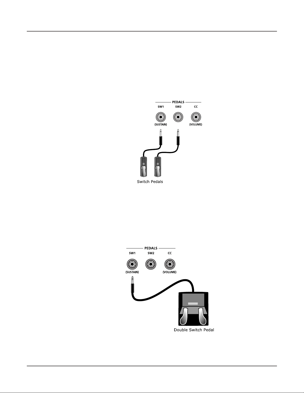
Connecting Pedals
Artis SE connected to powered speakers and headphones
Artis SE connected to a mixer, powered speakers and headphones
2-6
Page 21
Connecting Pedals
Plug your switch, dual switch, half-damper or continuous control pedals into the
corresponding jacks on Artis SE rear panel. We recommend using the Kurzweil pedals
described in Pedals (Optional) on page 1-2. However you can use almost any switch or
continuous control pedal that adheres to the following specications.
Switch Pedals
Getting Started
Connecting Pedals
1/4 inch tip-sleeve (mono) plug or, 1/4 inch tip-ring-sleeve plug
congured as dual switches (TS and RS) or 2 terminal continuous
pedal (half-damper).
Continuous Control
(CC) Pedals
10 kΩ linear-taper potentiometer, 1/4 inch tip-ring-sleeve (stereo)
plug with the wiper connected to the tip.
Pedals are all independently assignable within each Zone of every Multi.
Here are the default control settings for the three pedals used by Artis SE:
SW 1 Pedal Sustain (MIDI 64)
SW 2 Pedal Sostenuto (MIDI 66)
CC Pedal Expression (MIDI 11)
NOTE : Ensure that pedals are plugged in before powering up the
Artis SE and do not step on the switch pedals when powering up, as
the pedal type and state of the pedal is detected as part of the power
up sequence.
Connecting a Single Switch Pedal
When a single switch pedal is plugged into the SW1 Pedal jack on the rear panel, a single
switch pedal will, by default, act like a sustain pedal. When a single switch pedal is plugged
into the SW2 Pedal jack, the single switch pedal will, by default, act like a sostenuto pedal.
is can be changed by editing, as described in Multi Mode on page 7-1.
2-7
Page 22
Getting Started
Connecting Pedals
If you are not using a Kurzweil switch pedal, make sure it’s connected before you turn on the
Artis SE. is ensures that the pedal will work properly (it might function in reverse—o
when it’s down and on when it’s up—if you turn on your Artis SE before plugging in the
pedal). Similarly, don’t press any of your switch pedals while powering up, as the Artis SE
veries each pedal’s orientation during power-up. If you’re pressing a pedal, you might cause
it to work in reverse.
See Switch Pedal Problems on page 12-5 if you are having trouble with your switch pedal.
Connecting a Dual Switch Pedal
You can connect a dual switch pedal with a single stereo plug, such as the Kurzweil KFP-2S,
into the SW1 Pedal and SW2 Pedal jacks. Both SW1 and SW2 can support a dual pedal each
allowing up to 4 pedals to be utilized by the Artis SE. ese are enumerated as SW1a, SW1b,
SW2a and SW2b. e Artis SE will recognize dual pedals that are wired as TS and RS, such
as the KFP-2S.
2-8
Page 23
Getting Started
Connecting Pedals
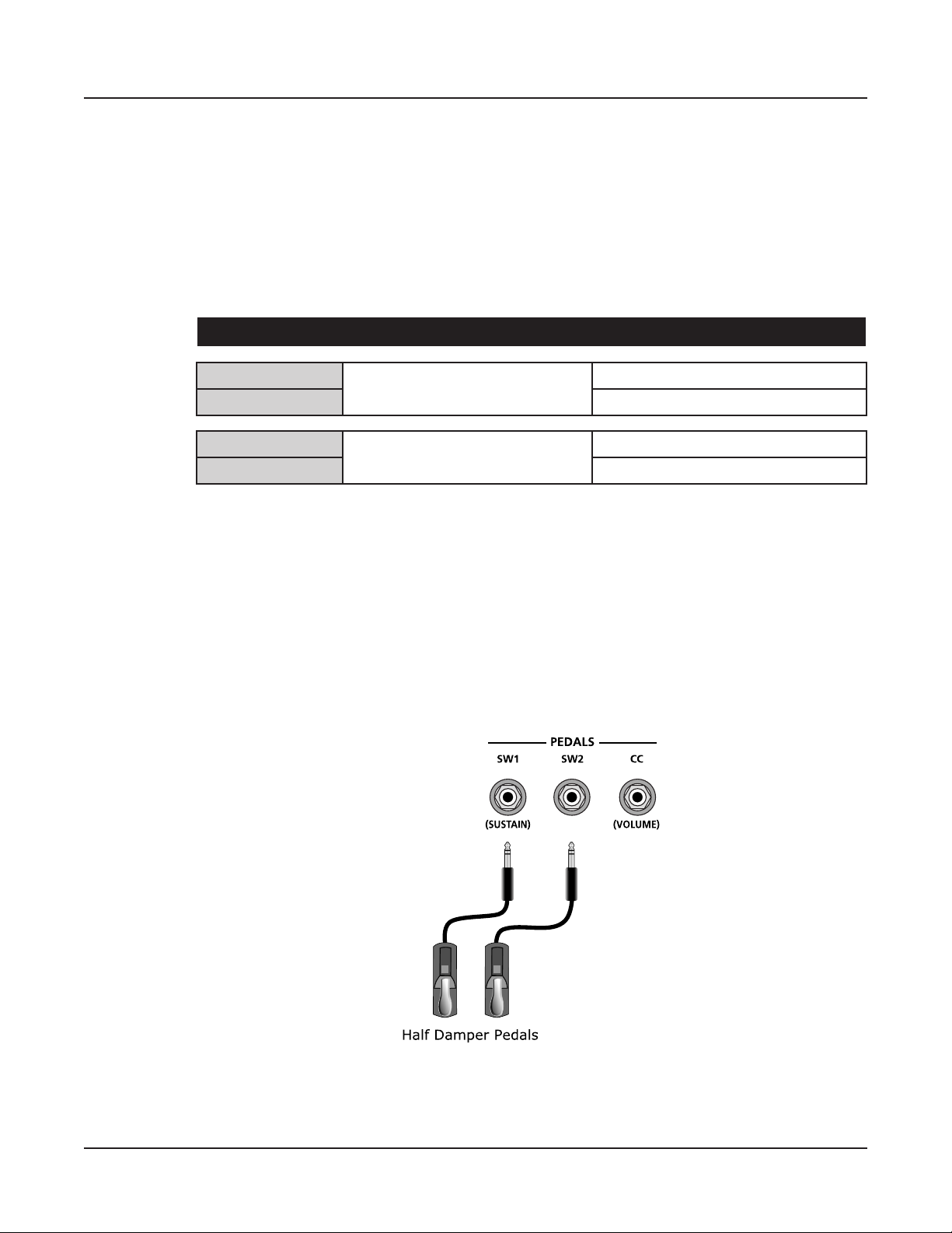
If you’re not familiar with traditional piano technique, the sostenuto (center) pedal on a
grand piano allows one to hold chords in the bass while continuing to play the melody
without the latter notes sustaining. Any keys that are down when you depress the pedal will
sustain when you let go of the keys, but new notes played afterward will not be sustained.
Releasing the pedal puts things back to normal. Of course it can be programmed to do other
functions as well.
e defaults assignment for the Switch Pedals is summarized in the table below.
Pedal Single Switch Default Dual Switch Default
SW1a
Sustain (MIDI CC#64)
SW1b Sostenuto (MIDI CC#66)
SW2a
Sostenuto (MIDI CC#66)
SW2b Soft (MIDI CC#67)
Connecting a Half Damper Pedal
Half Damper pedals where the wiper is connected to the tip (such as the KORG DS-1H™)
can be connected to the SW1 and SW2 inputs on the rear panel. Some pedals have the wiper
connected to the ring, and these pedals will require an adapter to work with the Artis SE.
Half damper pedals can be used to control external software and sound modules via MIDI,
enabling ner control of sustain than a standard switch pedal.
Sustain (MIDI CC#64)
Sostenuto (MIDI CC#66)
2-9
Page 24
Getting Started
Connecting MIDI
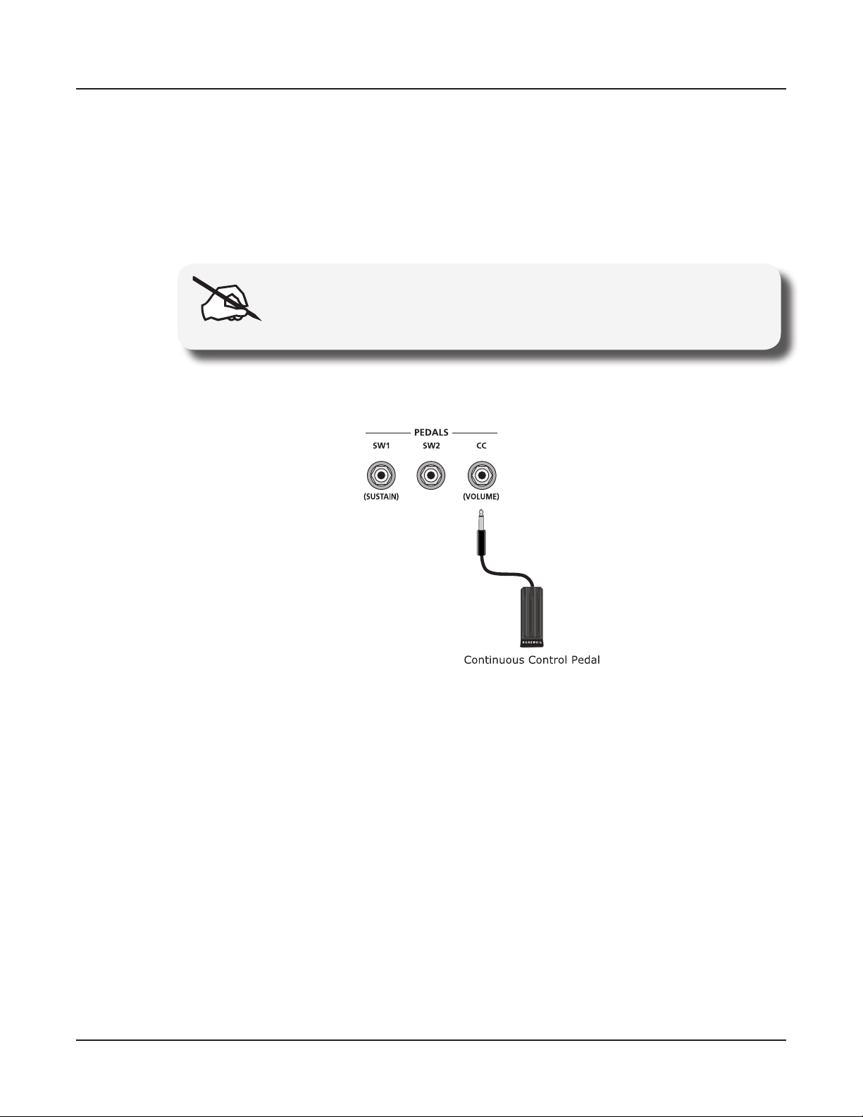
Connecting a Continuous Control Pedal
A continuous control pedal can be very useful for controlling volume, wah, or other eects
by foot.
e Kurzweil CC-1 continuous control pedal will work best with the Artis SE, but it is also
possible to use third-party continuous control pedals designed for synthesizers.
See Continuous Control and Half-Damper Pedal Problems on page 12-5 if you are having
trouble with your continuous control pedal.
NOTE : Using a third-party continuous control pedal / volume pedal
may or may not be satisfactory depending on how it is constructed.
2-10
Page 25
Connecting MIDI
In addition to being a performance-suited musical instrument, the Artis SE is a powerful, but
easy to use MIDI controller. For descriptions of how to customize the Artis SE as a MIDI
controller, and how to use its MIDI controller capabilities to their fullest potential, see Multi
Mode on page 7-1.
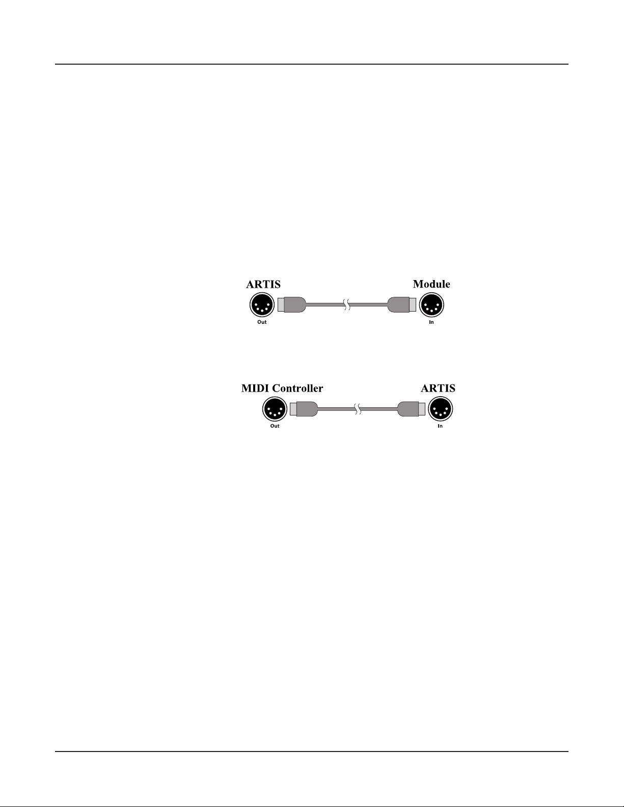
Basic MIDI Hookup
To use the Artis SE as a MIDI controller for another sound module, use a MIDI cable to
connect the MIDI port marked “Out” to the MIDI input port of the module that you want
to control.
Getting Started
Connecting MIDI
To control the Artis SE using another MIDI controller, use a MIDI cable to connect the
MIDI port marked “In” to the MIDI output port of the controller that you will be using.
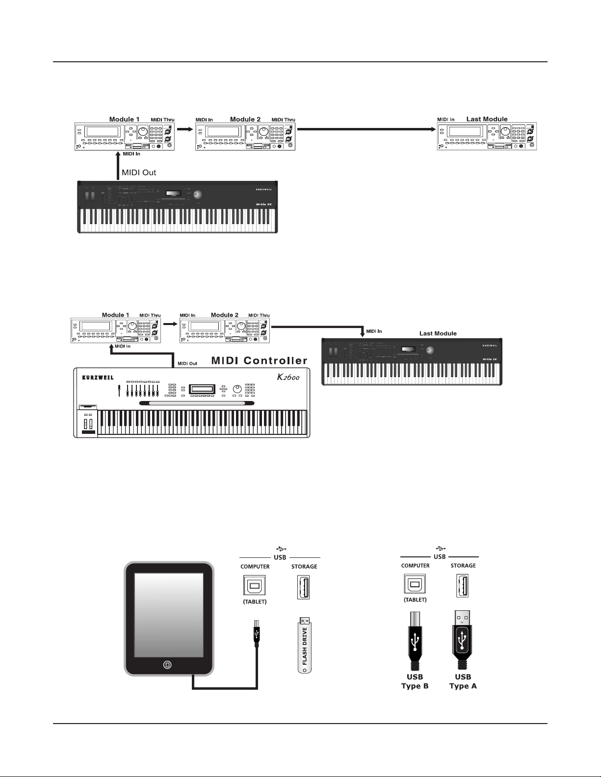
Connecting More Sound Modules
In order to connect multiple sound modules to be controlled by a single MIDI controller,
the Artis SE must either be :
(1) Used as the controller.
(2) Or the last module in the MIDI daisy chain.
e reason is because the Artis SE does not include a ru MIDI port; however, this simply
means that the Artis SE must be at the start or at the end of the MIDI daisy chain.
Using the Artis SE as the controller, connect the MIDI Out port to the MIDI In port of
the rst module, and then connect that module’s MIDI ru port to the input of the next
module, and so on, until the last module is connected.
e MIDI chain should end in the MIDI In port of the last module.
2-11
Page 26
Getting Started
Connecting MIDI
Scenario 1: Artis SE as the MIDI controller
Scenario 2: Artis SE as the last module in the MIDI chain
2-12
Connecting to a Computer Sequencer
To connect the Artis SE to a computer/tablet, simply connect Artis SE using the provided or
compatible cable.
Page 27

If you wish to use your own cable, make sure that it is a Type-A-to-Type-B USB cable (the
USB computer port of the Artis SE being Type B). By default, the Artis SE will act as a
MIDI controller (rather than a hard drive) when connected to a computer.
Selecting Programs and Multis
e Artis SE supports two types of sounds. e rst type is a Program, and these are
normally a single instrument, such as a piano, or an organ. A Program is similar to a “preset”
or “patch” on other synthesizers. e Artis SE has 256 factory Programs, and the space for a
further 256 user Programs. Both factory and user Programs are arranged into 16 categories
of 16 sounds each.
e other type of sound is the more complex Multi. A Multi is a combination of Programs
arranged as layers and splits across the keyboard. ey are similar to setups, from the
Kurzweil PC series, SP series and K2 series, and are similar to Combis or Multis from other
synthesizers. e Artis SE has 128 factory Multis and space for a further 256 user Multis.
Similar to Programs, user Multis are arranged into 16 categories of 8 sounds each.
e Artis SE has been designed so that it is quick and easy to select Programs and Multis
from the front panel.
Getting Started
Selecting Programs and Multis
Use the following guide to audition the factory sounds on the Artis SE. Program and Multi
selection are covered in more detail later in the manual.
e Artis SE always starts in Multi Mode. If you wish to play a Program, simply press the
Program Button. e Program Button will light up to show that Progam Mode is selected.
To return to Multi Mode, from a dierent mode, simply press the Multi button. If the User
button is illuminated, then you are in the User Bank. Press the User Button to return to
the Factory Bank, and the LED will go out. In the Factory Bank, press one of the Category
Buttons to change Category, and that Category Button will light up. Once you are in your
desired Category, press one of the Program/Multi buttons to select the Program/Multi you
want.
To select another Program or Multi within the same Category, just press a Program/Multi
Button, or use the Alpha Wheel, or + and - Buttons.
To select a Program or Multi in another Category but not in the other Bank (Factory/User),
press the desired Category Button, followed by the desired Program/Multi Button. e
Alpha Wheel and + and - Buttons will select the next Category once you get to the end of
the current Category. Pressing the Category Button will select the Default Program for that
Category. e Default Category Program can be set by the user for each Category. By default
the Artis SE has the Default Program for each Category set to the rst Program of each
Category. To change the Default Category Program, see page 6-5.
e Sliders, Wheels, Pedals and Buttons can control each of the factory Programs and Multis,
to produce variations to the sound. Don’t forget to try these out as you explore the factory
sounds on the Artis SE.
2-13
Page 28

Chapter 3
Features of the Artis SE
is chapter will help familiarize you with the features of the Artis SE. Many of these features
have both general functions and mode-specic functions. For more in-depth descriptions of
these features, refer to the chapters on the individual modes.
Powering Up Defaults
Features of the Artis SE
Powering Up Defaults
In general, the Artis SE will always remember the last selection made by the user. However,
powering up the Artis SE resets some of these settings back to their power-on defaults.
Parameters Reset To Defaults At Power-On
• Transpose set to 0 semitones.
• MIDI Channel set to 1.
• At startup Multi Mode is set to the Favorite (or category default) Multi of the Piano1
category.
• Entering Program Mode the selected Program is set to the Category Default Program
of the factory Piano1 category.
Parameters Remembered After Power-On
• User Programs.
• User Multis.
• Favorites.
• Default Program per Category.
• Default Multi per Category.
• EQ On/O state.
• Global Mode parameters Velocity Map, View, Destination & Pedal overrides, and
AutoPowerO parameters
3-1
Page 29
Features of the Artis SE
The Front Panel
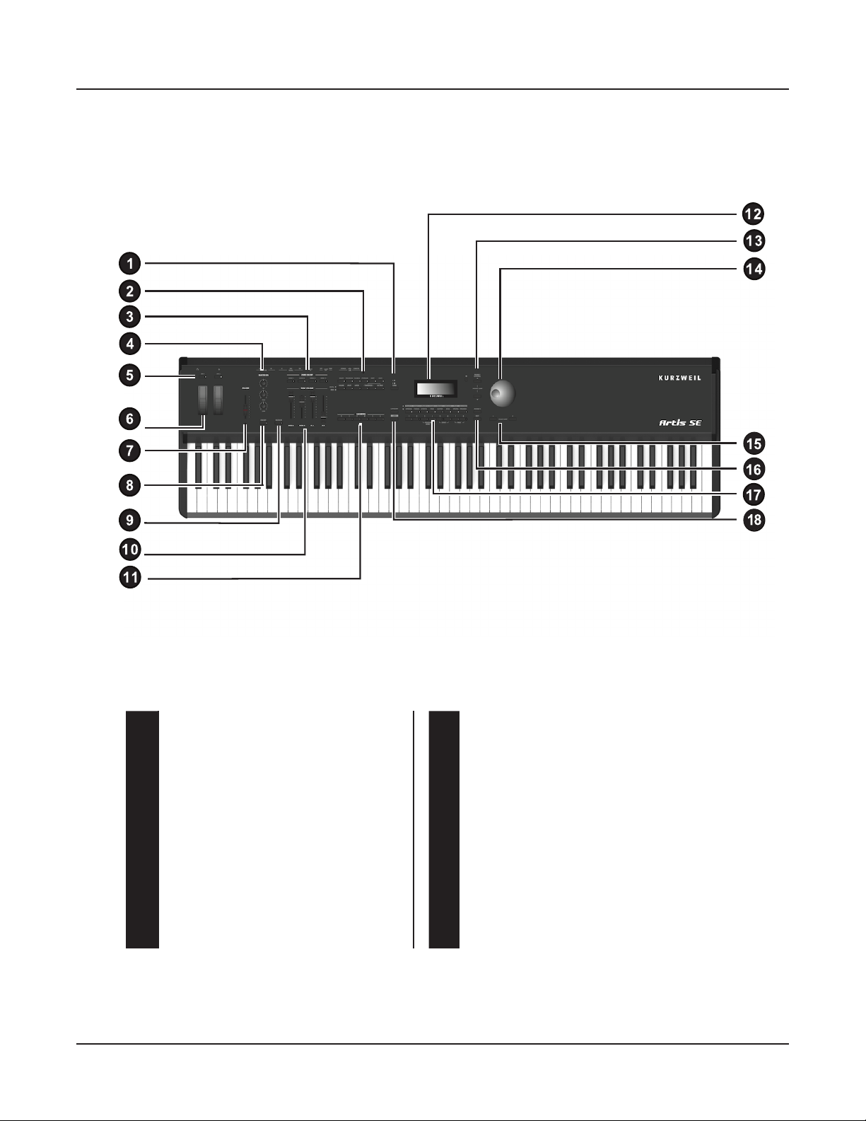
The Front Panel
All the controls for Artis SE, both musical and navigational, are on its front panel
3-2
.
1 BANK Button 10
2 Mode and Function Buttons 11
3 ZONE Mute Buttons 12
4 MASTER EQ Controls 13
5 Programmable Switches 14
6 Pitch and Modulation Wheels 15
7 VOLUME slider 16
8 EQ ON/OFF switch 17
9 FILTER-FX switch 18
ZONE VOLUME Sliders
FAVORITES buttons
Display and display contrast knob
Parameter/Channel buttons
Alpha Wheel
Plus/Minus select buttons
ASSIGN and EXIT buttons
Category Select and Multi/Program
select buttons
CATEGORY and USER switches
Page 30
Real Time Controls
Pitch Wheel
e Pitch Wheel is the left most of the two wheels. It is spring-loaded, such that its center
position is restored when it is not being used. at is because the Pitch Wheel is used for
pitch-bending notes—its “o” position is in the center. Pushing the Pitch Wheel up bends
the pitches of all notes up. Pulling the Pitch Wheel down bends the pitches of all notes
down.
For some Programs the Pitch Wheel will not bend notes that are held by the sustain pedal.
is is how many Guitar and Bass Programs are congured, allowing played notes to be
bent over sustained notes. For User Multis, you can program the bend amount for the Pitch
Wheel using the Bend Range parameters described on page 8-10
Features of the Artis SE
Real Time Controls
Modulation Wheel
e Modulation Wheel is the right most of the two wheels.
Unlike the Pitch Wheel, the Modulation Wheel is not spring
loaded, and can be set to and left in any position between fully
up and fully down. Typically, the Modulation Wheel is assigned
to a parameter that alters some aspect of the sound (e.g., vibrato,
lter depth) when changed.
When a KB3 Program is in use, the Modulation Wheel is
assigned to control distortion.
Programmable Switches (SW1 and SW2)
In Program Mode, the two Switch buttons may be pre-assigned to change the sound in
dierent ways, for example enabling layers or eects.
In Multi Edit Mode, you can assign the Switch buttons to control Program and eects
parameters, or send MIDI CC messages to external equipment.
e SW1 and SW2 button LEDs illuminate red when either switch is active.
3-3
Page 31

Features of the Artis SE
Audio Level Controls
Foot Switches and Controllers
e Artis SE has sophisticated Pedal controller options allowing up to 4 Switch Pedals or
up to 2 Half Damper Pedals as well as a Continous Controller Pedal to be connected. By
default the Switch Pedals control SW1a - Sustain, SW1b - Sostenuto, SW2a - Sostenuto and
SW2b - Soft. e CC Pedal controls expression by default.
Each Zone in a factory Multi may have dierent pedal assignments, and pedals are all
independently assignable within each Zone of a user Multi.
Audio Level Controls
Volume Slider
is controls the output level of the Headphone and Audio Out jacks on the rear panel.
Audio In
On the back panel of the Artis SE you will nd a ⅛” sized stereo audio jack labelled AUDIO
IN.
You can plug your MP3 player into the Artis SE and play along with the recorded music.
ere is no volume control for the Audio Input on the Artis SE itself, so you should control
the mix volume of the Audio Input from the MP3 player itself.
Master EQ
3-4
e Master EQ allows you to have realtime control over the frequency response of all audio
generated in either Program or Multi Modes. When the Master EQ On/O button is “On”,
the rotary knobs can change the high, middle & low frequencies of the audio.
If the LED on the Master EQ On/O button is lit, this indicates that the Master EQ section
is now “on”.
Page 32

Features of the Artis SE
Audio Level Controls
e HI & LOW EQ’s are shelving type lters, and the MID is a bell curve type lter
centered around approximately 1.4 kHz.
Frequency Gain
HI
MID
LOW
~6.6 kHz -24dB to +15dB
~1.4 kHz -24dB to +15dB
98 Hz -24dB to +15dB
When the Master EQ is on, the audio signal ows as per the diagram above. When it is o,
the signal ows as per the digram below.
Sliders and Filter-FX button
e four sliders on the left of the front panel are assigned to control dierent sound
parameters and eects for each Multi or Program.
3-5
Page 33

Features of the Artis SE
Mode Buttons
In Multi Mode the FILTER-FX switch functions as a “shift” button, changing the slider
functions when activated. When the FILTER-FX switch is disabled the sliders control the
volume for each Zone. When the FILTER-FX switch is enabled, the sliders control lters,
FX, and other parameters. e assignment of each slider can be changed in Multi Edit mode.
e sliders can also send MIDI continuous controller values to a computer or external MIDI
equipment.
In Program Mode the FILTER-FX switch is always active. In most Programs the Sliders
labeled Filter-A and Filter-B are assigned to control a lter or EQ parameter in order to
control brightness. Slider FX-D controls reverb amount, while Slider FX-C usually controls a
second eect such as delay/echo amount.
If you select a KB3 Program, the four sliders act like tonewheel organ drawbars. For KB3
Programs, the sliders operate in a similar way to a Hammond organ, i.e. pulling the slider
towards you increases the drawbar amount.
For standard Programs the sliders have the minimum value when they are towards the player
and maximum value when they are pushed away from the player.
ZONE ON/OFF Buttons
Zones are the independent regions of the keyboard that make up a Multi, for additional
information see About Zones on page 7-4.
Pressing a Zone button will mute or unmute the Zone. An active/unmuted Zone button has
a lit green LED. e LED of an inactive/muted Zone button is not lit.
Mode Buttons
e Mode buttons are located on the left side of the Artis SE front panel.
3-6
Page 34

Multi Button
is button’s LED is illuminated when you are in Multi Mode, which is the default Mode.
e Artis SE always boots up in this mode.
From any other mode, pressing the Multi button enters Multi Mode (described in Multi
Mode on page 5-1 and, in further detail, in Multi Mode on page 7-1). In Multi Mode,
you can select dierent congurations of Programs, controller assignments, and MIDI
channel assignments.
Program Button
Pressing the Program button enters Program Mode (described in Program Mode on page
5-2). In Program Mode, you can select and play dierent sounds (or “Programs”). is
button’s LED is illuminated when you are in Program Mode.
Global Button
Features of the Artis SE
Mode Buttons
Pressing the Global button enters Global Mode (described in Global Mode on page 5-1
and, in further detail, in Global Mode on page 9-1). In Global Mode, you can edit
parameters that control the overall behavior of the Artis SE. ese parameters include tuning,
transposition and velocity. Additionally, you can perform a Hard or Soft Reset. is button’s
LED is illuminated when you are in Global Mode.
CAUTION: Performing a Hard Reset will erase ALL User Program and
User Multis, and will reset Global settings to a factory state.
Storage Button
Pressing the Storage button enters Storage Mode, allowing data to be loaded into or saved
from, the Artis SE. Choices include the storage device connection (USB for ash drives, PC
for computers or tablets).
Edit Button (Multi Edit Mode)
When in Multi Mode, the Edit button will initiate Multi Edit mode. From here, you can
navigate through the editable parameters of a multi and make specic changes. When
you change a parameter, the Save button will light. You can then continue to select other
parameters (using Navigation controls), or hit the Exit button to abandon changes, or hit the
Save button to save your changes as a User Multi. Refer to Multi Edit Mode on page 8-1 for
more information.
3-7
Page 35

Features of the Artis SE
Function Buttons
Save Button
e Save button is located on the left side of the LCD screen.
In Program Mode, pressing the Save button saves the current position of the sliders, switches
and wheels as a User Program. (See Saving User Programs on page 6-11)
In Multi Mode, pressing the Save button saves a copy of the current Multi. e copy is saved
with the states of the Multi Zone Mute buttons but does not include the current state of
the physical controllers (i.e. moved Sliders, Mod Wheel etc.). Other controller states can be
edited in Multi Edit Mode. (See Saving User Multis on page 8-16 .)
e Save button’s LED is illuminated once you have made changes to the current Program or
Multi to indicate that the Program or Multi has changed.
Function Buttons
Sound
Split
e Sound button controls the destination of MIDI notes produced by playing the Artis SE
keyboard. Pressing the Sound Button will step through the options. e LOCAL and MIDI
LEDs will indicate the status, where a lit LED indicates that MIDI messages are being sent
to that destination. e available options are LOCAL, MIDI, or LOCAL and MIDI.
When LOCAL and MIDI are selected, MIDI notes will be sent to the local Artis SE sound
engine, as well as the MIDI Out and USB Computer ports. When only LOCAL is selected,
MIDI notes will only be sent to the local Artis SE sound engine. When only MIDI is
selected, MIDI notes will only be sent to the MIDI Out and USB Computer ports.
Pressing the Split Button while in either Program or Multi Mode performs the Split
Function, creating a new Zone using the lower range of keys. is allows you to split
Programs and Multis such that keys in one region of the keyboard produce dierent sounds
than another region.
Hitting Split in Program Mode automatically puts the Artis SE into Multi Mode. From
there, the split program can be saved as a User Multi.
In Multi Mode, if all four zones are already employed, a Split cannot be performed, and the
display will read “No more zones.”
3-8
Page 36

Layer
Pressing the Layer Button while in either Program or Multi Mode performs the Layer
Function, creating a new zone using the entire keyboard range. is allows you to layer
Programs and Multis such that more than one sound can be produced by striking a single
key.
Hitting Layer in Program Mode automatically puts the Artis SE into Multi Mode. From
there, the layered program can be saved as a User Multi.
In Multi Mode, if all four zones are already employed, a Layer cannot be performed, and the
display will read “No more zones.”
Transpose -/+ and Octave
e Transpose – and + and Octave buttons are located at the left of the Artis SE display,
just below the Mode buttons
Features of the Artis SE
Function Buttons
e Transpose buttons can be used to change the tuning of notes played on the Artis SE
keyboard in semitones (ST), also known as half steps. is is a convenient way to change
the key of a song without learning to play it in a dierent key. e Transpose buttons also
transpose MIDI notes sent to the USB and MIDI out ports.
Press the Transpose – or + buttons to transpose the Artis SE keyboard down or up by one
semitone. e top line of the display shows the current transposition value. To transpose up
and down by octave intervals (12 ST), press the Octave button, then select Transpose + or
Transpose – .
e maximum transposition value possible is +/–36 semitones.
e LEDs of the Transpose buttons indicate whether the current Program is transposed
up (Transpose + LED is lit) or transposed down (Transpose – LED is lit). When there
is no transposition, neither Transpose button is lit. Pressing both Transpose – and +
simultaneously will reset the transposition to 0.
3-9
Page 37

Features of the Artis SE
Favorites
Favorites
e six Favorites buttons allow Programs and Multis to be saved and quickly re-selected.
Pressing a Favorite button will load the favorite Program or Multi stored in that location.
To save the current Program or Multi as a Favorite, hold down any of the Favorite buttons
for 3 seconds. When the Favorite has been successfully saved, you will be notied by a
message temporarily displayed on the LCD screen.
Category and sound selection
e Category Select section allows you to quickly and easily get access to sounds in either
Program or Multi Modes. You select the Category of sound you want, then use the Program /
Multi buttons to select any of the sounds in that Category.
CATEGORY button
e Artis SE makes it easy to select sounds by instrument type. e 8 Category buttons can
access 16 Categories, arranged in two rows. An LED indicates the currently active row, and
the Category button will let you switch rows. If a Category button is lit, the red LED next
to the labels will indicate which Category row you using. Switching Category rows will send
you to the rst (default) sound in the new Category. Default sounds can be customized; see
Choosing Category Default Programs on page 6-5 and Choosing Category Default Multis on
page 7-4
USER button
e User button allows you to select saved User Multis and Programs, arranged in 2 banks,
for a total of 16 User Programs or 16 User Multis within each Category.
3-10
Page 38

A/B Bank button
When a Category has been selected in Program Mode, you can select any
of the 16 sounds of that Category by using the A/B Bank button. e
Program/Multi selection buttons are numbered from 1 to 8; selecting Bank
B will give you access to the next 8 Programs in the current Category. In
Multi Mode, each factory Category has only eight selections, so the A/B
Bank button has no eect unless you have saved User Multis.
Navigation
e navigation section of the Artis SE front panel includes the LCD display, (-) and (+)
Value buttons, Param / Channel ▲ and ▼ buttons, and the Alpha Wheel.
The LCD Display
e Display has 2 rows of 20 characters each. e top row shows the current context (Mode,
Transposition, Channel, or other). e lower row shows the current Program/Multi ID and
name, or a parameter available for editing. Text in the lower row may scroll to permit more
characters to be read.
Features of the Artis SE
Navigation
MULTI Xpose:0
1 Concert Piano SE
You can adjust the display contrast by turning a small potentiometer knob located, above the
Alpha Wheel.
In Multi mode the top line of the display shows the current Mode and MIDI transposition,
and the lower line displays the current Multi number and name.
In Multi Edit Mode, the top line of the display shows the current mode, Zone number, the
current parameter number and the total number of available parameters.
3-11
Page 39

Features of the Artis SE
Navigation
In Global Mode, the top line of the display shows the current mode, the current parameter
and the total number available. e bottom line shows the selected parameter name.
(–) and (+) Value Buttons
Use the (-) and (+) buttons to scroll through the list of values for the currently selected
parameter. Pressing both (-) and (+) buttons simultaneously is referred to as the Value Jump
double button press. Depending on the selected parameter, Value Jump can select the next
Category default Program/Multi, jump to commonly used values, and reset parameters to
default values. For more information, see Value Jump on page 3-13.
Param / Channel Buttons
In Program Mode, pressing the Param/Channel ▲button will increase the MIDI transmit
channel by one. Pressing the Param/Channel ▼button will reduce the MIDI transmit
channel by one.
When the highest or lowest MIDI transmit channel is reached, the list will wrap back to the
last or rst MIDI transit channel respectively. e top line of the display shows the current
MIDI transmit channel.
In the other Modes—Multi Edit & Global—pressing the Param/Channel ▲ and ▼
buttons will scroll through the parameter list for the current Mode.
NOTE : The Param / Channel buttons are not used in Multi Mode.
Alpha Wheel
In Multi and Program Modes you can use the Alpha Wheel to scroll through the list of
available Programs/Multis. In Multi Edit Mode you can change values for the currently
selected parameter—turning the Alpha Wheel counter-clockwise will select the previous
value and turning the Alpha Wheel clockwise will select the next value.
When saving a new User Multi or Program, the Alpha Wheel allows you to scroll through
alphanumeric characters to enter a new name. You can turn the Alpha Wheel slowly to
change the value by one increment or turn it quickly to jump several increments.
ASSIGN and EXIT Buttons
3-12
e Exit button can be used to navigate out of Multi Edit Mode, Save dialogs, the Split/
Layer dialogs, Global Mode and Storage Mode, without saving changes.
Page 40

Pressing and holding the Assign button when in the Split function allows you to set the
keyboard split location by striking the desired key. In Multi Edit Mode, pressing and holding
the Assign button allows you to select a Zone by pressing a Zone On/O button. In Multi
Edit Mode, pressing and holding the Assign button allows you to to set the HiKey or LoKey
parameter (when selected) for the current Zone by striking a key on the Artis SE keyboard.
In Multi Edit Mode, pressing and holding the Assign button allows you to quickly select the
Destination parameter for a controller of the current Zone by moving the desired controller.
Double Button Presses
Several pairs of the buttons on the Artis SE have timesaving secondary functions when
pressed simultaneously—think of them as keyboard shortcuts. For convenience of reference,
descriptions of all of the double-button press functions appear below.
Value Jump
In Program Mode, the Value Jump double button press selects the rst
Program of each Category, as well as the Category Default Program of
each Category (if a Category Default Program has been set).
Features of the Artis SE
Double Button Presses
For more information on choosing a new Category Default Program,
see Choosing Category Default Programs on page 6-5.
In Multi Mode, the Value Jump double button press selects the rst
Multi of each Category, as well as the Category Default Multi of each
Category (if a Category Default Multi has been set).
In Multi Edit Mode, pressing the Value Jump double button press resets
the current parameter to its default value, or jumps between multiple
useful values.
Parameter Jump
In Multi Edit Mode and Global Mode, pressing both the Param/
Channel ▲ and ▼ buttons simultaneously will jump to commonly
used parameters or to the rst of a group of similar parameters.
In Program Mode, pressing the Parameter Jump double button press
allows you to change the current MIDI channel by using the numbered
Program/Multi Select buttons.
Reset Transposition
Pressing both Transpose + and Transpose – simultaneously will restore the current Program
or Multi to having no transposition.
3-13
Page 41

Features of the Artis SE
Double Button Presses
Program Demo
In Program Mode only, pressing the 3 & 4 Program/Multi buttons performs the Program
Demo Function. e Program Demo Function plays the Demo Song for the currently
selected Program. Press the Exit button to exit the Program Demo at any time.
If you press these buttons from any other Mode, the display will give you a message
indicating you are not in Program Mode.
Demo
Pressing the 5 & 6 Program/Multi buttons performs the Demo Function (described in
further detail in Program and Song Demo Functions on page 5-3). With the Demo Function
selected, you can hear a demonstration song that showcases many of the features of Artis SE.
Panic
Pressing the 7 & 8 Program/Multi buttons simultaneously deactivates all sounding notes and
control messages and sends an “all notes o” message and an “all controllers o” message on
all 16 MIDI channels.
3-14
Assign
Pressing a key, switch, or moving a controller while holding down the Assign assign performs
“Intuitive Entry.”
Assign + Zone (1–4) Button
In Multi Edit Mode, holding the Assign button and pressing a Multi Zone Mute button will
jump to selecting that Zone. e currently selected Zone number can be seen on the top line
of the page.
Page 42

Features of the Artis SE
Double Button Presses
Assign + Controller
In Multi Edit Mode, holding the Assign button and moving a controller (a Slider, Switch
button, Mod Wheel or Pedal) will jump to selecting the destination parameter of that
controller in the current Zone. is allows you to quickly assign a controller to a destination.
In Multi Edit Mode, holding the Assign button and moving the Pitch Wheel up or down
will jump to selecting the Bend Range Up or Bend Range Down parameters of the current
Zone.
Assign + Keyboard key
In Split Mode with the Split Key parameter selected, hold the Assign button and strike a key
to select the Split Key.
In Multi Edit Mode with the Low Key or High Key parameter selected, hold the Assign
button and strike a key to select the Low Key or High Key.
3-15
Page 43

Chapter 4
Terminology
is chapter provides denitions and descriptions for all of the Artis SE-specic terms used
in this manual. Some of the terms are also used by other manufacturers.
Since there are no standard denitions for some of these terms, they are described here to
avoid confusion. All of these terms appear with the rst letter capitalized as proper nouns in
this manual to make it easy to distinguish between the generic term and the Artis SE specic
term.
Terminology
In addition to the terms below, and to avoid confusion, any Artis SE specic feature,
connector or control will have the rst letter capitalized to distinguish it from the generic
term. Physical button labels will be shown in bold type.
Program
Multi
A Program is an instrument sound that plays on a MIDI
channel. e sound of each Program can be modied by
parameters that are assigned to the controllers (Sliders,
Switch buttons, Mod Wheel, and Pedals).
See Program Mode on page 6-1 for more information on
Programs.
A Multi allows up to 4 instrument sounds (Programs) to be
played from the keyboard at once. A Multi has 4 Zones,
each with its own keyboard range, Program, MIDI channel,
and controller assignments.
See Multi Mode on page 7-1 for more information on
Multis.
4-1
Page 44

Terminology
KB3
Zone
Split
Layer
Kurzweil’s organ modelling simulation of the original
Hammond B3 with Leslie rotary speaker emulation.
A keyboard region of a Multi that has its own Program,
MIDI channel, and controller assignments.
See About Zones on page 7-4 for more information on
Zones.
A Split is a Multi containing at least two Zones that have
keyboard ranges that don’t overlap. is allows dierent
keyboard ranges to play dierent instrument sounds.
See The Split Function on page 7-5 for more information
on Splits.
A Layer is a Multi containing at least two Zones that have
overlapping keyboard ranges. is allows a single keyboard
range to play multiple instrument sounds.
MIDI Bank
Mode
Hard Reset
See The Layer Function on page 7-6 for more information
on Layers.
A group of 128 Programs that can be navigated by MIDI
compatible software or hardware.
An operating status with a unique group of operations.
See The Operating Modes on page 5-1 for more information
on Modes.
A process that returns Artis SE back to a Factory state. All
User Programs & User Multis are erased. All Global Mode
parameters are reset back to their default settings as well.
4-2
Page 45

Terminology
Soft Reset
Object
KUF le
A process that resets all Global Mode parameters to their
default factory settings. User Programs & User Multis are not
erased.
Anything that can be named, saved, deleted, or edited (i.e., a
Program or a Multi).
KUF (Kurzweil Unied File) le is a special le that has the
objects and operating system combined that is used to update
the Artis SE.
4-3
Page 46

Chapter 5
The Operating Modes
is chapter will help familiarize you with the operating Modes of the Artis SE.
Each of the Modes (Multi, Program, Global, Multi Edit, and Storage) has its own individual
chapter. Save is covered in both the Program and Mulit Edit chapters. e Functions (Sound,
Split, Layer, Transpose and Demos) are described in this chapter in Functions on page 5-3.
The Operating Modes
Multi Mode
Multi Mode
Multi Mode is the default Mode for the Artis SE. Multi Mode allows you to select and play
Multis.
A Multi allows up to 4 instrument sounds (Programs) to be played from the keyboard at
once. A Multi has four Zones, each with its own keyboard range, Program, MIDI channel,
and controller assignments. To enter Multi Mode from another Mode, press the Multi
Mode button.
For more detailed information on Multi Mode, see Multi Mode on page 7-1.
5-1
Page 47

The Operating Modes
Program Mode
Program Mode
In Program Mode, instrument sounds (Programs) can be selected and played. e sound of
each Program can be modied by parameters that are assigned to the controllers (Sliders,
Switch buttons, Mod Wheel, and Pedals). Modied Programs can be saved as User Programs
by pressing the Save button.
To enter Program Mode from another Mode, press the Program Mode button.
For more detailed information on Program Mode, see Program Mode on page 5-2.
Global Mode
CAUTION: THIS MODE CONTAINS CERTAIN OPERATIONS THAT
CANNOT BE UNDONE. Read Global Mode on page 9-1
Global Mode allows you to edit global parameters and MIDI settings, load and save User
Programs and Multis, or restore factory defaults with a hard or soft reset. To enter Global
Mode from another Mode, press the Global Mode button. See Global Mode on page 9-1
for further information.
Storage Mode
is Mode allows you to save or load les from a computer or other USB-equipped storage
device. Begin by pressing the Storage Mode button. On the main Storage menu, four
options are available: Device (PC or USB), Store, Load (Overwrite) or Load (Fill). Pressing
the Exit Button while in Storage Mode will return to the previous Mode the instrument was
in.
Valid le formats for loading are: .ART, .PC3, .P3K, .PLE, .SPX. and .ASE (Artis SE
extension). When a le has been selected to load, pressing the + Button or Assign Button will
load the selected le. Pressing the Exit Button or - Button will return to the main Storage
page. See Storage Mode on page 10-1 for further detail.
Multi Edit Mode
5-2
Multi Edit Mode allows you to edit pre-existing Multis.
To enter Multi Edit Mode press the Edit Button while in Multi Mode. e Edit button does
apply in Program Mode; however, hitting Split or Layer while in Program mode will also put
the Artis SE into Multi Edit mode. See Multi Edit Mode on page 8-1 for more detail.
Page 48

Functions
Five Functions , also described in Function Buttons on page 3-8, have dedicated buttons.
The Sound Function
is controls the overall MIDI output of the Artis SE. Hitting Sound will step through three
possible congurations:
The Operating Modes
Functions
Local
MIDI
Local+MIDI
is will override any Zone-specic settings (see Destination (Dest) on page 8-6 for more
info.)
MIDI data is sent only to the Artis SE sound engine. MIDI OUT is disabled.
MIDI data is sent only through MIDI OUT. e sounds of the Artis SE are disabled.
MIDI data is sent both to the Artis SE sound engine and through the MIDI OUT.
The Split Function
See The Split Function on page 6-6 (for Splits in Program Mode) and The Split Function on
page 7-5 (for Splits in Multi Mode).
The Layer Function
See The Layer Function on page 5-3 (for Layers in Program Mode) and The Layer Function on
page 7-6 (for Layers in Multi Mode).
Transpose Functions
e Transpose and Octave buttons will transpose the entire keyboard. See Transposition on
page 6-5 and Transposition on page 7-4 for more information.
Program and Song Demo Functions
Pressing the 3 & 4 Program/Multi buttons simultaneously will play a brief demonstation
using the current Program. Pressing the 5 & 6 Program/Multi buttons simultaneously will
play built-in Demo Songs designed to demonstrate the capabilities of the Artis.
Song Demos will display a song title and the total number of available Demos; Program
Demos will display the Program name. Use the Alpha Wheel, Value buttons or the Param/
Channel ▲ and ▼ buttons to select another Song Demo from the list.
e Program/Multi button LEDs blink when using the Demo Function. Press the Exit
Button to exit either Demo Function.
5-3
Page 49

Chapter 6
Program Mode
is chapter will help familiarize you with the features of Program Mode.
Programs are essentially the dierent sounds of a MIDI instrument—they are preset
instrument sounds equivalent to the “patches,” “presets,” or “voices” that you nd on other
keyboards.
Program Mode
About Program Mode
About Program Mode
To enter Program Mode from another Mode, press the Program mode button. While you
are in Program Mode, the Program button’s LED is illuminated.
When you enter Program Mode after powering on the Artis SE, the Category Default
Program in the Piano 1 category will be selected, either Program 1 (factory default) or a
Program you pick as a Category Default Program for the Piano 1 category. See Choosing
Category Default Programs on page 6-5.
If you enter Program Mode from another Mode, the current Program will be the last selected
Program on the current MIDI Channel.
Selecting Programs
e Artis SE features two Program Banks, one of which contains 256 factory Programs, and
the other Bank is reserved for up to 256 User Programs. Both the factory and User Banks are
split into 16 categories of 16 Programs each.
When you are in Program Mode, there are a few ways to select Programs.
• To select a Program in the current Category, press the relevant Program/Multi button.
• To select a Program in a dierent Category, press the Category button of choice and
then a Program/Multi button to select from the 16 Programs in the Category.
• To select the default Program from a Category, simply press the relevant Category
Button.
6-1
Page 50

Program Mode
Selecting Programs
• Choosing a Program in the user Categories, while in the factory Categories, or
• e Alpha Wheel and the – and + buttons allow you to advance through the
• If a Program is assigned to a Favorite button, pressing that button will go directly to
Program Demo
If you want to quickly hear what a Program sounds like in performance, try the Program
Demo Function
In Program Mode only, pressing the 3 & 4 Program/Multi buttons performs the Program
Demo Function. e Program Demo Function plays a Demo Song for the currently selected
Program.
Press the Exit button to exit Program Demo.
choosing a Program in a factory Category while in a user Category, requires pressing
the User button, followed by a Category button and then a Program/Multi button.
Programs one at a time. When you reach the end of the Category, advancing further
will go the the next Category.
the assigned Program.
If you try to use the Program Demo Function from any other Mode, the display will give you
a message indicating you are not in Program Mode.
The Display
In Program Mode, initially the top line of the display shows the current Mode, Transposition
(XPOSE) and MIDI channel.e Program ID number and name are displayed on the
second line. If a slider is moved, the second line displays the parameter aected and the value
change.
Pop Up Messages
Some actions, such as moving a slider, cause the display to show pop up messages on the
second line indicating the controller assignment. After a short time the display returns to
show the current Program.
PROG Xpose:0 Ch:1
1 Concert Piano
6-2
Page 51

Alpha Wheel & – and + Value Buttons
Use the Alpha Wheel, or the – and + buttons below the Alpha Wheel, to change the current
Program. Turning the Alpha Wheel counter-clockwise or pressing the – button will select
the previous Program and turning the Alpha Wheel clockwise or pressing the + button will
select the next Program. When the highest or lowest Program is reached, the list will wrap
back to the last or rst Program respectively.
When scrolling through the Program list, the list moves through each Category, both factory
and User.
Program Mode
Selecting Programs
Value Jump Buttons
In Program Mode, the Value Jump double button press selects the rst Program of each
Category, as well as the Category Default Program of each Category (if a Category Default
Program has been set).
For more information on choosing a new Category Default Program for each Category, see
Choosing Category Default Programs on page 6-5.
If the User button is selected, Value Jump works the same way.
6-3
Page 52

Program Mode
Selecting Programs
Category & Program/Multi Buttons
e Category buttons allow you to select Programs by instrument type simply by pressing a
button. You can select one Category button at a time and the current Category button’s LED
is lit.
ere are 16 categories to choose from, arranged in two rows, as labelled. Use the Category
button to the left to switch between rows. An LED will light to indicate the selected row.
Each Category contains 16 Programs of a single instrument type arranged in 2 Banks (A and
B). First select the Category you want by pressing a Category button, then select one of the 8
Programs in the current Bank by pressing one of the Program/Multi buttons numbered from
1 to 8. Press the Bank button to switch between Bank A and B.
You can also press one of the instrument Category buttons, then turn the Alpha Wheel
clockwise or press the + button to advance to the next Program in the Category. When you
reach the end of a Category, the Artis SE automatically advances to the beginning of the
next Category. is will also work in reverse if you turn the Alpha Wheel counter-clockwise
or press the - button. In this case when you reach the beginning of a Category, the Artis SE
automatically advances to the end of the previous Category. ese controls will scroll through
all of the categories in the current Bank, and the next Bank will be automatically selected
when the end of the current Bank is reached. e 16 User Categories come after the factory
ones, but only non-empty programs can be selected this way.
6-4
Page 53

Choosing Category Default Programs
You can choose a “Category default program” from each Category that will be recalled
each time you press that Category’s button. To save a Category default program, rst select
a Program using any Program select method (Alpha wheel, – and + buttons, Category
buttons, Program/Multi buttons). A Category button for the current Category will have a
lit LED. Next, press and hold the currently lit Category button until the display shows the
message “default program saved.” e Category default program has now been successfully
saved.
You can only save a Program as a Category default for the Category that it belongs to. If you
try to save a Category default program to a dierent Category, you will see a pop up message
in the display.
Choosing Favorites
You can save six Favorite Programs (or Multis) from any Category to the six Favorite buttons
beneath the display. Once saved, these favorite Programs can be recalled from any Mode with
a single button press. To save the currently selected Program or Multi to a Favorite button,
press and hold a Favorite button until the display shows the message “Saved to fav. button.”
Program Mode
Transposition
Transposition
e Transpose buttons can be used to change the tuning of notes played on the Artis SE
keyboard in semitones (ST), also known as half steps. is is a convenient way to change the
key of a song without learning to play it in a dierent key. e Transpose buttons are located
to the left of the display. e Transpose buttons also transpose MIDI notes sent to the USB
and MIDI out ports.
Press the Transpose – or + buttons to transpose the Artis SE keyboard down or up by one
semitone. e top line of the display shows the current transposition value. Pressing both
Transpose – and + simultaneously will reset the transposition to 0. To transpose up and
down by octave intervals (12 ST), press the Octave button, then use the Transpose – and +
buttons to change the octave.
e maximum transposition value possible is +/–36 semitones.
6-5
Page 54

Program Mode
Parameter Assignments
e LEDs of the Transpose buttons indicate whether the current Program is transposed up
(Transpose+ LED is lit) or transposed down (Transpose– LED is lit). When there is no
transposition, neither Transpose button is lit.
Parameter Assignments
In Program Mode, each Program has factory set Program and Eect parameters assigned
to physical controllers (Sliders, Switch buttons, Mod Wheel, and Pedals). A parameter
assignment can modify an instrument sound during a performance to add variation or
expression. Moving a controller changes the value of the parameter. Any time you do this,
the display shows the Controller name, assigned parameter, and value.
For most programs, the Sliders labeled Filter-A and Filter-B are assigned to lter or EQ
parameters in order to control brightness. e Slider labeled FX B is usually assigned to
control reverb amount, and the Slider labeled FX A is sometimes assigned to control delay
amount or another eect. e remaining controls may have dierent assignments depending
on the selected Program.
If you make changes to the current Program using any of the controllers, the Save button’s
LED lights to indicate that a change has been made to that Program. For more information
on the Save button, see Save User Programs on page 6-11.
The Split Function
e Split Function allows you to split Programs such that keys in one region of the keyboard
produce dierent sounds than another region.
When you create a Split in Program Mode, you are in fact creating a Multi with two
active Zones (see Multi Mode on page 7-1, for more information on Multis). Multis
are congurations of four Zones, each of which may have its own Program and controller
assignments.
e Split Function is convenient, as you do not need to use Multi Edit Mode to congure
Zone key ranges, Programs, and volumes. You can simply hit the Split button, and the Artis
SE automatically creates a Multi with two active Zones. e Program you were initially using
in Program Mode is used in the right hand of the Split, as the Program for Zone 1.
After hitting the Split button you can choose a “Split Program” that will be used in the left
hand of the Split as the Program for Zone 2.
Once you have saved your Split as a User Multi, you can continue to add Split or Layer
Zones to the Multi until you reach the maximum of four active Zones. e Artis SE will
display a message if you have already reached the maximum of four active Zones (see Multi
Mode on page 7-1, for more information on Multis).
6-6
Page 55

Program Mode
The Split Function
ere are four parameters (described below) that determine the behavior of the Split. ese
can be accessed by using the Param/Channel buttons.
Split Program
Move the Alpha Wheel or use a Category/Program button to select the Split Program.is
determines the Program for the left-hand side of the Split keyboard. Initially the last used
Split Program will be selected, or, if this is the rst time using the Split Function since powerup, the default Split Program (106 Motown Bass) will be selected.
Split Volume
Press the Param/Channel ▲ button to select the Split Volume parameter. is determines
the balance of the left and right-hand Programs. By default, the Split Volume is set to 0,
which results in both Programs having the same volume. When set to a positive number, the
volume for the right hand Program is decreased. When set to a negative number, the volume
for the left hand Program is decreased. To set the Split Volume, use the Alpha Wheel, or –
and + buttons. Split Volume can be set to any number between -127 and 127. Pressing the
Value Jump button pair resets the volume to 0.
6-7
Page 56

Program Mode
The Layer Function
Split Key
Press the Param/Channel ▲button again to select the Split Key parameter. is sets the
keyboard key that will be the boundary between the left and right hand Programs on the
keyboard. e selected key will be the highest note for the left-hand Split Program. All keys
higher than the Split Key will play the right-hand Program. By default, the Split Key is set to
B3. e Split Key can be selected holding the Assign button down and then striking the
desired key on the keyboard. e Split Key can also be selected by using the Alpha Wheel or
– and + buttons. Split Key can be set to any key between A0 and C8.
Split Transpose
Press the Param/Channel ▲ button again to select the Split Transpose parameter. is
parameter allows you to transpose the left-hand Split Program in octaves so that you can play
it in higher or lower octaves. Use the Alpha Wheel or – and + buttons to set the Transpose
value. Transpose can be set to -24, -12, 0, 12, and 24. By default, Split Transposition is set to
+12.
Saving a Split
After setting the Split parameters, the Split can be saved as a Multi so that it can easily be
recalled in Multi Mode. Press the Save button to the left of the display to begin the saving
process.
See Save User Multis (page 7-8) in the Multi Mode Chapter for details on saving. Once
you have saved your Split as a Multi, you can continue to add Split or Layer Zones to the
Multi until you reach the maximum of four active Zones.
See the Split Function (page 7-5) and the Layer Function (page 7-6) in the Multi Mode
Chapter. Also, once you have saved your Split as a Multi, you can edit controller assignments
and other Multi parameters in Multi Edit Mode (see Multi Edit Mode on page 8-1 for
details).
The Layer Function
Pressing the Layer button while in Program Mode will perform the Layer function. e
Layer Function allows you to layer Programs and Multis such that more than one sound can
be produced by striking one key.
When you create a Layer in Program Mode, you are in fact creating a Multi with two active
Zones (see Multi Mode on page 7-1, for more information on Multis). As previously
described, Multis are congurations of four Zones, each of which may have its own Program
and controller assignments.
6-8
Page 57

Program Mode
The Layer Function
e Layer Function is convenient, as you do not need to use Multi Edit Mode to congure
Zone key ranges, Programs, and volumes. You can simply hit the Layer button, and the
Artis SE automatically creates a Multi with two active Zones. e Program you were using
in Program Mode is used as the Program for Zone 1. After this you can choose a “Layer
Program” that will be used as the Program for Zone 2.
Once you have saved your Layer as a Multi, you can continue to add Layer or Split Zones in
Multi Mode until you reach the maximum of four active Zones. e Artis SE will display a
message when you have reached the maximum of four active Zones (see Multi Mode on page
7-1, for more information on Multis)
ere are three parameters (described below) that determine the behavior of the Layer.
Layer Program
e Layer Program parameter is the default parameter. It determines the “Layer Program”
that will be layered on top of the Program you were using in Program Mode. Initially the last
used Layer Program will be selected, or, if this is the rst time using the Layer Function since
power-up, the default Layer Program (224 Add a Pad 2) will be selected. Choose a Layer
Program using the Category and Program/Multi buttons, the Alpha Wheel, or the – and +
buttons.
Layer Volume
Press a Param/Channel button to select the Layer Volume parameter. is determines the
volumes of the Program from Program Mode and the Layer Program. By default, the Layer
Volume is set to 0, which results in both Programs having the same volume. When set to a
positive number, the volume for the Program from Program Mode is decreased. When set to
a negative number, the volume for the Layer Program is decreased. To set the Layer Volume,
use the Alpha Wheel or – and + buttons. Layer Volume can be set to any number between
-127 and 127. Pressing the Value Jump button pair resets the volume to 0.
6-9
Page 58

Program Mode
Changing the Transmit MIDI Channel
Layer Transpose
Press the Param/Channel ▲button again to select the Layer Transpose parameter. is
parameter allows you to transpose the Layer Program in octaves so that it sounds octaves
higher or lower than the other Program you are layering on top of. Use the Alpha Wheel or
– and + buttons to set the Transpose value. Transpose can be set to -24, -12, 0, 12, and 24.
By default, Layer Transpose is set to 0.
Saving a Layer
After setting the Layer parameters, the Layer can be saved as a Multi so that it can easily be
recalled in Multi Mode. Press the Save button to the left of the display to begin the saving
process. See Save User Multis (page 7-8) in the Multi Mode Chapter for details on saving.
Once you have saved your Layer as a Multi, you can continue to add Split or Layer Zones to
the Multi until you reach the maximum of four active Zones. See the Split Function (page
7-5) and e Layer Function (page 7-6) in the Multi Mode Chapter. Also, once you have
saved your Layer as a Multi, you can edit controller assignments and other Multi parameters
in Multi Edit Mode (see Multi Edit Mode on page 8-1 for details).
Changing the Transmit MIDI Channel
e current MIDI Transmit channel is shown on the right side of the top line of the display.
Press the Param/Channel ▲ or ▼ buttons to change the MIDI Transmit channel. A
dierent Program can be selected for each MIDI Channel. All channels can be triggered
simultaneously from an external MIDI sequencer or computer. e Aux FX Chains of the
Program on the currently selected MIDI Channel are used for Programs on all Channels.
Pressing both Param/Channel ▲ and ▼ at the same time (Param Jump)will let you select a
MIDI transmit channel (1-8) using the numbered Category buttons.
6-10
Page 59

Panic
Program Mode
Panic
If a MIDI Channel is disabled, the Program name is shown with parenthesis and the message
“Channel disabled” on the line above.
MIDI Channels are enabled/disabled in Global Mode, see Channel Enable (ChanEn) on
page 9-6.
Pressing the 7 and 8 Program/Multi buttons (Panic) simultaneously deactivates all sounding
notes and resets controller values by sending an “All Notes O ” message and a “Reset All
Controllers” message on all 16 MIDI channels.
Saving User Programs
If you make changes to the current Program using any of the controllers, the Save button’s
LED lights to indicate that a change has been made to that Program.
To save the changes you’ve made, press the Save button once. e Save button’s LED begins
to blink, allowing you to set the ID number and rename the Program. e display shows the
rst available ID number and the current Program name.
6-11
Page 60

Program Mode
Saving User Programs
You can save Programs with ID numbers from 257 to 512. When you initially press the Save
button, the Artis SE always selects the next available unused ID number and displays the
current Program name. After specifying the Program ID number and name, press the Save
button again to complete the saving process.
Changing ID Numbers
To change the ID number, turn the Alpha Wheel or use the + and – buttons to select the
new ID number. You can also use the Bank, Category and Program/Multi buttons to select
an ID number, which is useful for organizing User Programs by Category. To do this, rst
select a Bank and Category button, then select a Program/Multi button to select an ID
within that category.
Naming a User Program
To rename the new Program press a Param/Channel button until you see “Rename Prog
as:”.
Rename Prog as: 1/2
Mixed Choir
_
e display shows the current Program name. Use the Alpha Wheel to select characters for
the new Program name. Press the + or – button to move the cursor to the other characters.
Program names can total 16 characters in length.
Locating a saved User Program
Press the Save button to complete the saving process, or press the Exit button to exit without
saving. After successfully saving, the Program will be selected in Program Mode in the User
Bank. To nd the Program again later, make sure to press the User bank button under the
Category button.
6-12
Page 61

Chapter 7
Multi Mode
is chapter will help familiarize you with the features of Multi Mode.
Multis are congurations of four Zones, each of which may have its own Program, controller
assignments, and MIDI transmit channel. A Zone can also be congured to control an
external sound module or computer software through a MIDI or USB cable.
Multi Mode
About Multi Mode
About Multi Mode
To enter Multi Mode from another Mode, press the Multi Mode button.
While you are in Multi Mode, the Multi button’s indicator LED is illuminated.
When you enter Multi Mode after powering on the Artis SE, the Category Default Multi in
the Piano1 Category will be selected, either Multi 1 (factory default) or a Multi you pick as a
Category Default Multi, see Choosing Category Default Multis on page 7-4.
e rst 16 factory Multis (IDs 1-16 in the Piano 1 and Piano 2 categories) each have a
single active Zone containing piano, electric piano or guitar. When using these Multis you
can quickly add additional string, bass and pad layers by using the Zone On/O buttons to
turn on Zones 2-4. ese Multis are useful for composition, performance, or as a template
for creating simple User Multis. When the Filter-FX button is disabled, the 4 sliders can be
used to adjust the volume of each Zone. Check out the rest of the 128 factory Multis to nd
other inspiring Multis and some more complex congurations.
About Zones
Zones are the independent regions of the keyboard that make up a Multi.
A Multi has four Zones, each one having its own Program, controller assignments, and
MIDI transmit channel. Zones can be mutually exclusive regions of the keyboard, or they
can overlap. A Zone can also be congured to control an external sound module or computer
software through a MIDI or USB cable.
7-1
Page 62

Multi Mode
Selecting Multis
Muting Zones
Pressing a Zone On/O button will mute or unmute the Zone. An active/unmuted Zone
button has a lit LED. e LED of an inactive/muted Zone button is not lit.
Selecting Multis
When you are in Multi Mode, there a few ways to select Multis.
• To select any Multi in the current Category, press a Program/Multi button.
• To select a Multi in a dierent Category, press the Category Button of choice and
then the Program/Multi Button to select from the 8 Multis in the Category.
• To select the Category Default Multi, simply press a Category Button.
• To switch between the Factory and User Multis, press the User Button, followed by
a Category button and then a Program/Multi button. Unlike factory Multis which
have 8 Multis per category, User Multis have 16 Multis per category. Two sets of 8
User Multis can be selected for each Category by pressing the Bank button.
• e Alpha Wheel and the + & – buttons allow you to advance through the Multis
one at a time. When you reach the end of the Category, advancing further will go to
the next Category.
• If a Multi is assigned to a Favorite Button, pressing that button will go directly to the
assigned Multi.
The Display
In Multi Mode, the top line of the display shows the current Mode and MIDI transposition.
e lower line shows the Multi ID number and name.
Pop Up Messages
Actions such as moving a controller cause the display to show pop up messages. After a short
time the display returns to show the current Multi.
7-2
Page 63

Alpha Wheel and – & + Value Buttons
Use the Alpha Wheel or the Value buttons, to the right of the display below the Alpha
Wheel, to change the current Multi. Turning the Alpha Wheel counter-clockwise or
pressing the – button will select the previous Multi and turning the Alpha Wheel clockwise
or pressing the + button will select the next Multi. When the highest or lowest Multi is
reached, the list will wrap back to the last or rst Multi respectively.
Value Jump Buttons
In Multi Mode, the Value Jump double button press selects the rst Multi
of each Category, as well as the Category Default Multi of each Category
(if a Category Default Multi has been set). For more information on
choosing a new Category Default Multi, see Choosing Category Default
Multis on page 7-4. If the User button is selected, Value Jump works the
same way.
Multi Mode
Selecting Multis
Category & Program/Multi Buttons
e Category buttons allow you to select Multis from a group of 8 Multis per category.
Multis are not categorized by instrument type, so the instruments used in a Multi may not
match its category name (category instrument names only apply to selecting Programs in
Program Mode). You can select one Category button at a time and the current Category
button’s LED is lit.
Each Category contains 8 Multis. First select the Category you want, then select one of the 8
Multis by pressing any of the Program/Multi buttons numbered from 1 to 8.
7-3
Page 64

Multi Mode
Transposition
Choosing Category Default Multis
Choosing Favorites
You can choose a “Category Default Multi” from each Category that will be recalled each
time you press that Category’s button. To save a Category Default Multi, rst select a Multi
using any Multi select method (Alpha wheel, – & + buttons, Category buttons, Program/
Multi buttons). A Category button for the current Category will have a lit LED. Next, press
and hold the currently lit Category button until the display shows a message indicating that
the Category Default Multi has been saved.
You can save one Category Default Multi per Category button.
You can save six Favorite Multis (or Programs) from any Category to the six Favorite
Buttons. Once saved, these Favorite Multis can be recalled from any Mode with a single
button press. To save the currently selected Multi to a Favorite Button, press and hold a
Favorite Button until the display shows the message “Multi saved to fav. button.”
Transposition
e Transpose buttons can be used to change the tuning of notes played on the Artis SE
keyboard in semitones (ST), also known as half steps. is is a convenient way to change the
key of a song without learning to play it in a dierent key. e Transpose buttons are located
to the left of the display. e Transpose buttons also transpose MIDI notes sent to the USB
and MIDI out ports.
Press the Transpose – or + buttons to transpose the Artis SE keyboard down or up by one
semitone. e top line of the display shows the current transposition value. Pressing both
Transpose – & + simultaneously will reset the transposition to 0. To transpose up and
down by octave intervals (12 ST), press the Octave button and use – Transpose + buttons.
e maximum transposition value possible is +/–36 semitones.
e LEDs of the Transpose buttons indicate whether the current Multi is transposed up
(Transpose + LED is lit) or transposed down (Transpose – LED is lit). When there is no
transposition, neither Transpose button is lit.
7-4
Page 65

NOTE : The transposition created this way is applied to all
Programs in the Zones within the Multi. The Zone layout on the
keyboard however still remains xed.
The Split Function
Pressing the Split button while in Multi Mode performs the Split Function. e Split
Function allows you to split Multis such that keys in one region of the keyboard produce
dierent sounds than another region.
When you create a Split in a Multi, you are in fact activating a new Zone within the current
Multi. If the current Multi already has its maximum of four active Zones and you press
the Split function button, then a message will appear on the display indicating that you
have reached the maximum of four active Zones. Once you have saved your Split, you can
continue to add Split or Layer Zones to the Multi until you reach the maximum of four
active Zones.
Multi Mode
The Split Function
e Split Function is convenient, as you do not need to use Multi Edit Mode to congure
Zone key ranges, Programs, and volumes. You can simply press the Split button, and the
Artis SE automatically activates another Zone in the Multi for you. e previously active
Zones are used in the right hand of the Split. After this you can choose a “Split Program”
that will be used in the left hand of the Split as the Program for the newly activated Zone.
ere are four parameters (described below) that determine the behavior of the Split. Press
the Param/Channel buttons to the right the display to access each of the Split parameters.
Split Program
e Split Program parameter determines the Program for the left-hand side of the Split, also
known as the “Split Program.”
Initially the last used Split Program will be selected, or, if this is the rst time using the Split
Function since power-up, the default Split Program (106 Motown Bass) will be selected .
Choose a Split Program using the Category and Program/Multi buttons, the Alpha Wheel, or
the – & + buttons.
7-5
Page 66

Multi Mode
The Layer Function
Split Volume
is parameter determines the volumes of the left and right-hand Zones. By default, the Split
Volume is set to 0, which results in all Zones having the same volume. When set to a positive
number, the volume for the right hand Zone(s) is decreased. When set to a negative number,
the volume for the left hand Zone(s) is decreased. To set the Split Volume, use the Alpha
Wheel, or – & + buttons. Split Volume can be set to any number between -127 and 127.
Pressing the Value Jump button pair (– & +) resets the volume to 0.
Split Key
is sets the keyboard key that will be the boundary between the left and right hand Zones
on the keyboard. e selected key will be the highest note for the left-hand Split Program.
All keys higher than the Split Key will play the right-hand Zone(s). By default, the Split Key
is set to B3. e Split Key can be selected using Assign , by holding down the Assign
button and then striking the desired key on the keyboard. e Split Key can also be selected
by using the Alpha Wheel, or – & + buttons. Split Key can be set to any key between A0
and C8.
Split Transpose
Hit the Param/Channel button to select the Split Transpose parameter. is allows you to
transpose the left-hand Split Program in octaves so that you can play it in higher or lower
octaves. Use the Alpha Wheel or – & + buttons to set the Transpose value. Transpose can be
set to -24, -12, 0, 12, and 24. By default, Split Transposition is set to +12.
Saving a Split
After setting the Split parameters, press the Save button to the left of the display to begin the
saving process. See Save User Multis (page 7-8) for details on saving. Once you have saved
your Split, you can continue to add Split or Layer Zones to the Multi until you reach the
maximum of four active Zones. Also, once you have saved your Split, you can edit controller
assignments and other Multi parameters in Multi Edit Mode (see Multi Edit Mode on page
8-1 for details).
The Layer Function
Pressing the Layer button while in Multi Mode performs the Layer Function. e Layer
Function allows you to layer Multis such that more than one sound can be produced by
striking one key.
7-6
Page 67

Multi Mode
The Layer Function
When you create a Layer in a Multi, you are in fact activating a Zone within the current
Multi. If the current Multi already has its maximum of four active Zones and you press
the Layer function button, then a message will appear on the display indicating that you
have reached the maximum of four active Zones. Once you have saved your Layer, you can
continue to add Layer or Split Zones to the Multi until you reach the maximum of four
active Zones.
e Layer Function is convenient, as you do not need to use Multi Edit Mode to congure
Zone key ranges, Programs, and volumes. You can simply press the Layer button, and the
Artis SE automatically activates another Zone in the Multi to layer with the previously active
Zones. After this you can choose a “Layer Program” that will be used as the Program for
newly activated Zone.
ere are three parameters (described below) that determine the behavior of the Layer. Press
one of the Param/Channel buttons to the right of the display to access each of the Layer
parameters.
Layer Program
e Layer Program parameter determines the program that will be layered on top of the
previously active Zones.
Initially the last used Layer Program will be selected, or, if this is the rst time using the
Layer Function since power-up the default Layer Program (224 Add a Pad 2) will be selected.
Choose a Layer Program using the Category and Program/Multi buttons, the Alpha Wheel,
or the – & + buttons.
Layer Volume
Press the Param/Channel ▲ button to select the Layer Volume parameter. is determines
the volumes of the Layer Program and the previously active Zone(s). By default, the Layer
Volume is set to 0, which results in all Zones having the same volume. When set to a positive
number, the volume for the previously active Zone(s) is decreased. When set to a negative
number, the volume for the Layer Program is decreased. To set the Layer Volume, use the
Alpha Wheel, or – & + buttons. Layer Volume can be set to any number between -127 and
127.
Pressing the Value Jump button pair (– & +) resets the volume to 0.
Layer Transpose
Press the Param/Channel ▲ button again to select the Layer Transpose parameter. is
allows you to transpose the Layer Program in octaves so that it sounds octaves higher or
lower than the other Zone(s) you are layering on top of. Use the Alpha Wheel or – &
+ buttons to set the Transpose value. Transpose can be set to -24, -12, 0, 12, and 24. By
default, Layer Transposition is set to 0.
7-7
Page 68

Multi Mode
Saving User Multis
Saving a Layer
After setting the Layer parameters, press the Save button to the left of the display to begin
the saving process. See Save User Multis on page 7-8 for details on saving.
Once you have saved your Layer, you can continue to add Split or Layer Zones to the Multi
until you reach the maximum of four active Zones. Also, once you have saved your Layer,
you can edit controller assignments and other Multi parameters in Multi Edit Mode (see
Multi Edit Mode on page 8-1 for details).
Saving User Multis
To save changes to the current User Multi, or to save a changed Factory Multi to a User
Category, press the Save button once.
You can save Multis with ID numbers from 257 to 512. When you initially press the Save
button, Artis SE always selects the next available unused ID number and displays the current
Multi name.
Before Saving, you can specify the ID number and rename the Multi. After specifying the
Multi ID number and name, press the Save button again to complete the saving process.
Changing ID Numbers
To change the ID number turn the Alpha Wheel or use the – & + buttons to select the new
ID number. You can also use the Bank, Category and Program/Multi buttons to select an
ID number, which is useful for organizing User Multis by Category. To do this, rst press a
Bank and Category button, then press a Program/Multi button to select an ID within that
category.
If you choose an ID that is already in use, you will see an asterisk in the display after the ID
number. Press Save to overwrite the existing Multi, or choose a dierent ID.
Save Multi Over: 1/2
258*Samba Layers
7-8
Page 69

Naming a User Multi
Do you want save it?
[Assign]Save[Exit]No
To rename the new Multi press a Param/Channel button until you see “Rename Multi as:”.
e current Multi name will appear with a cursor line under the rst letter. Use the Alpha
Wheel to select characters for the new Program name. Press the + or – button to move the
cursor to another character.
Multi names can total 16 characters in length. Choosing a Space character, or pressing
Program/Multi button 6 will change the current character to a space. Pressing Program/
Multi button 7 will insert a space, moving the selected character to the right and deleting
the rightmost character if needed. Pressing Program/Multi button 8 will delete the selected
character, moving all characters to the left.
Rename Multi as: 2/2
Samba Layers
_
Multi Mode
Saving User Multis
Completing a User Multi Save
Press the Save button to complete the saving process, or press the Exit button to exit without
saving.
If you press a Mode button to switch Modes before you save the Multi, the display will show
a message. Press Save to continue in Save mode, or Assign to save the Multi with the current
settings, or Exit to cancel without saving.
After successfully saving, the Multi will be selected in Multi Mode in the User Bank. To nd
the Multi again later, make sure to press the User bank button while in Multi Mode.
7-9
Page 70

Chapter 8
Multi Edit Mode
is chapter will help you familiarize yourself with the features of Multi Edit Mode.
About Multi Edit Mode
NOTE: Before you read this chapter, be sure to read Multi Mode on page 7-1 for a full
description of Multis.
Multi Edit Mode
About Multi Edit Mode
Multi Edit Mode allows you to edit and create Multis—it gives you access to a Multi’s
common parameters and Zone-specic parameters. In this Mode, you can customize the
Program, controller assignments, and MIDI transmit channel (in addition to many other
parameters) of the Zones in a Multi. Any Multi edited or created in Multi Edit Mode is saved
to one of the 256 User locations.
To enter Multi Edit Mode press the Multi button followed by the Edit button. While you
are in Multi Edit Mode, the Multi button and Edit button LEDs are lit.
8-1
Page 71

Multi Edit Mode
The Parameters List
The Parameters List
A Multi has 86 Zone-specic parameters for each of the four Zones, and four common
parameters—altogether, the congurations of these multiple parameters determine the
behavior of the Multi. As you scroll through the list of parameters using the Param/Channel
Up ▲ button, the parameters appear in the following order (the parameters of course appear
in the reverse order if you scroll through the list with Param/Channel Down ▼ button):
List
No.
1 Local Program Program List 1 Concert Piano
2 Channel 1 to 16 1
3 Destination Local, MIDI, Local+MIDI Local+MIDI
4 Zone Status Active, Muted Active
5 Entry Volume None, 0 to 127 127
6 Entry Pan None, 0 to 127 None
7 Aux Send Level1 Prog, 0 to 127 Prog
8 Zone Channel FX Enabled, Disable Enabled
9 Transpose -128 to 127 ST 0
10 Low Key C-1 to G9 C-1
11 High Key C-1 to G9 G9
12 Low Velocity 1 to 127 1
13 High Velocity 0 to 127 127
14 Note Map Off, Linear, Constant Linear
15 MIDI Bank 0 to 127 Bank of Local Program
16 MIDI Program 0 to 127 Program Number of Local
17 Entry Program Change Off, On On
18 Bank Mode None, Ctl0, Ctl32, Ctl0/32, K2600 Ctl0/32
20 Bend Range Up Prog, 0 to 127 ST 2 ST
19 Bend Range Down Prog, 0 to 127 ST 12 ST
21 Mod Wheel Destination Multi Destination Controller List (none)
22 Mod Wheel Entry Value 0 to 127 (none)
23 Mod Wheel Exit Value 0 to 127 (none)
24 Slider 1 Destination Multi Destination Controller List (none)
25 Slider 1 Entry Value 0 to 127 (none)
26 Slider 1 Exit Value 0 to 127 (none)
27 Slider 2 Destination Multi Destination Controller List (none)
28 Slider 2 Entry Value 0 to 127 (none)
29 Slider 2 Exit Value 0 to 127 (none)
30 Slider 3 Destination Multi Destination Controller List (none)
31 Slider 3 Entry Value 0 to 127 (none)
32 Slider 3 Exit Value 0 to 127 (none)
33 Slider 4 Destination Multi Destination Controller List (none)
34 Slider 4 Entry Value 0 to 127 (none)
35 Slider 4 Exit Value 0 to 127 (none)
36 Slider 5 Destination Multi Destination Controller List (none)
37 Slider 5 Entry Value 0 to 127 (none)
38 Slider 5 Exit Value 0 to 127 (none)
39 Slider 6 Destination Multi Destination Controller List (none)
40 Slider 6 Entry Value 0 to 127 (none)
41 Slider 6 Exit Value 0 to 127 (none)
42 Slider 7 Destination Multi Destination Controller List (none)
43 Slider 7 Entry Value 0 to 127 (none)
44 Slider 7 Exit Value 0 to 127 (none)
45 Slider 8 Destination Multi Destination Controller List (none)
46 Slider 8 Entry Value 0 to 127 (none)
47 Slider 8 Exit Value 0 to 127 (none)
Parameter Range of Values Default Value
Program
8-2
Page 72

Multi Edit Mode
The Parameters List
List
No.
48 CC Pedal Destination Multi Destination Controller List (none)
49 CC Pedal Entry Value 0 to 127 (none)
50 CC Pedal Exit Value 0 to 127 (none)
51 Pedal Switch1a Mode Momentary, Toggled Toggled
52 Pedal Switch1a Destina-
53 Pedal Switch1a On Value 0 to 127 127
54 Pedal Switch1a Off Value 0 to 127 0
55 Pedal Switch1a Entry None, On, Off None
56 Pedal Switch1a Exit None, On, Off None
57 Pedal Switch1b Mode Momentary, Toggled Toggled
58 Pedal Switch1b Destina-
59 Pedal Switch1b On Value 0 to 127 127
60 Pedal Switch1b Off Value 0 to 127 0
61 Pedal Switch1b Entry None, On, Off None
62 Pedal Switch1b Exit None, On, Off None
63 Pedal Switch2a Mode Momentary, Toggled Toggled
64 Pedal Switch2a Destina-
65 Pedal Switch2a On Value 0 to 127 127
66 Pedal Switch2a Off Value 0 to 127 0
67 Pedal Switch2a Entry None, On, Off None
68 Pedal Switch2a Exit None, On, Off None
69 Pedal Switch2b Mode Momentary, Toggled Toggled
70 Pedal Switch2b Destina-
71 Pedal Switch2b On Value 0 to 127 127
72 Pedal Switch2b Off Value 0 to 127 0
73 Pedal Switch2b Entry None, On, Off None
74 Pedal Switch2b Exit None, On, Off None
75 Switch 1 Destination Multi Destination Controller List 0
76 Switch 1 Mode Momentary, Toggled None
77 Switch 1 On Value None, 0 to 127 None
78 Switch 1 Off Value None, 0 to 127 Toggled
79 Switch 1 Entry None, On, Off (none)
80 Switch 1 Exit None, On, Off 127
81 Switch 2 Destination Multi Destination Controller List 0
82 Switch 2 Mode Momentary, Toggled None
83 Switch 2 On Value None, 0 to 127 None
84 Switch 2 Off Value None, 0 to 127 Toggled
85 Switch 2 Entry None, On, Off (none)
86 Switch 2 Exit None, On, Off 127
Parameter Range of Values Default Value
Multi Destination Controller List (none)
tion
Multi Destination Controller List (none)
tion
Multi Destination Controller List (none)
tion
Multi Destination Controller List (none)
tion
List
No.
87 Aux Effect None, 1 to 9999 None
88 Aux Effect Channel (Channels used in Multi) (Channel of Zone 1)
89 KB3 Channel 1 to 16 (Channel of Zone 1)
90 Tempo 20 to 320 120
Common Parameter Range of Values Default Value
8-3
Page 73

Multi Edit Mode
Selecting Parameters
Selecting Parameters
The Display
In Multi Edit Mode, the top line of the display shows the current Mode, Zone number and
the current parameter number as well as the total the number of available parameters. e
bottom line of the display shows the current parameter and value.
EditMulti Zn:1 2/90
Channel:1
Scrolling Messages
Some parameters (such as Local Program) may be too long for the display, and will appear as
scrolling text on the lower line.
Param/Channel Buttons
Use the Param/Channel ▲ and ▼ buttons to scroll through the parameter list.
Alpha Wheel and Value buttons
Use the Alpha Wheel or the – & + buttons
below the wheel to change the parameter value—
turning the Alpha Wheel counter-clockwise or
pressing the – button will select the previous
value and turning the Alpha Wheel clockwise or
pressing the + button will select the next value.
Value Jump Buttons
Pressing the + and – buttons simultaneously resets the parameter to its default value.
Param Jump Buttons
Pressing the Param/Channel ▲ and Param/Channel ▼ buttons simultaneously jumps
parameters to specic jump points. e jump points are: Local Program, Transpose, Low
Key, ModWheel Destination, Slider1 Destination, Slider6 Destination, Slider11 Destination,
Pedal Switch Destination, Aux Eect Override (Common).
8-4
Page 74

Assign
In Multi Edit Mode, pressing and holding the Assign button while pressing a switch, key, or
moving a controller performs Assign in the following cases:
Assign + Zone (1–4) Button
Pressing and holding the Assign button while pressing one of the four Zone buttons will
select that Zone for editing. e currently selected parameter will be shown for the selected
Zone. If the current parameter is a Multi common parameter and not a Zone parameter,
Assign + Zone button will not do anything.
Assign + controller
Pressing and holding the Assign button while moving a controller (a slider, SW button, Mod
Wheel or any pedal) jumps to selecting the rst parameter of that controller in the current
Zone. is allows you to quickly assign a controller to a destination.
Multi Edit Mode
The Zone-specic Parameters
To edit the currently selected parameter, simply use the – & + buttons below the Alpha
Wheel. Pressing Value Jump (both – & + buttons simultaneously) will jump to a dierent
value depending on the parameter.
Assign + key
With the LoKey or HiKey parameter selected, hold the Assign button and strike a key on the
keyboard to set the LoKey or HiKey.
The Zone-specic Parameters
Each of the four Zones in Multi has multiple parameters that determine its behavior. Since
the Zones of a Multi are independent of each other, changing a parameter for a certain Zone
will not aect the parameters of any other Zone.
Local Program (Local Prog)
e Local Program parameter determines the Program to be loaded for the currently selected
Zone. You can set this parameter to any Artis SE Program (0 – 512). e display shows the
Program number and name (usually scrolling text).
Editing this parameter also changes the MIDI Bank and MIDI Program parameters,
described below.
8-5
Page 75

Multi Edit Mode
The Zone-specic Parameters
Channel
e Channel parameter determines the MIDI transmit channel for the currently selected
Zone. You can set this parameter to any of the 16 MIDI channels (1-16). You can assign
dierent Zones to the same channel, but only one Program can be loaded in a channel at a
particular time.
Destination (Dest)
e Destination parameter determines whether MIDI data generated by the currently
selected Zone is sent to the Artis SE sound engine, through the MIDI OUT port, or both.
You can set this parameter to any of the three destinations for this parameter:
NOTE: In the table below, MIDI OUT applies to both the 5-pin MIDI OUT and the USB
ports.
Local
MIDI
Local+MIDI
Select the desired destination depending on your needs. If you want to play the Artis SE,
but not send any MIDI information to other MIDI instruments, then select Local. If you
want to use the Artis SE strictly as a MIDI controller for the other modules in your MIDI
chain, then select MIDI. If you want to make use of the Artis SE’s sounds as well as use it as
a MIDI controller, then select Local+MIDI.
MIDI data is sent only to the Artis SE sound engine. MIDI OUT is
disabled.
MIDI data is sent only through MIDI OUT. e sounds of the Artis
SE are disabled.
MIDI data is sent both to the Artis SE sound engine and through
the MIDI OUT.
Zone Status (Status)
e Zone Status parameter determines whether the currently selected Zone is active or
muted. You can set this parameter to either of two states: Active or Muted. Use the Alpha
Wheel to make your selection.
8-6
Entry Volume (EntryVol)
e Entry Volume parameter determines the Volume MIDI message that the currently
selected Zone sends when the Multi is loaded. You can set this parameter to any volume
setting from None, 0 to 127.
Page 76

Entry Pan
e Entry Pan parameter determines the Pan MIDI message that the currently selected Zone
sends when the Multi is loaded. You can set this parameter to any pan setting from None, 0
(full left pan) to 127 (full right pan). To pan to center, select 64 for this parameter.
Aux Send Level (AuxSendLvl)
e Aux Send Level parameter determines the auxiliary eects send level for the Program of
the currently selected Zone. You can select any level from Prog, 0 to 127.
Pressing both - & + buttons simultaneously will set this parameter to 10. A value of Prog uses
the default Aux Send Level that the current Zone’s Program uses in Program mode. To enter
a value of Prog, use the Alpha Wheel or - & + buttons to scroll lower than 0.
For a description of the auxiliary eects of a Multi, see “About Auxiliary Effects” on page 8-15
and Common Parameters on page 8-15.
Multi Edit Mode
The Zone-specic Parameters
Zone Channel Effects (ZnChanFX)
Use the ZnChanFX parameter to enable or disable the Insert eects Chain of the Program
in each Zone. Some Zones set to Enable may be displayed as (Enable). is means that there
are not enough eects resources available for that Zone, and that Zone’s Insert eects are
not loaded. If you want to use the Insert eects Chain for a Zone displayed as (Enable), try
setting other Zones to Disable.
Transpose (Xpose)
e Transpose parameter determines the transposition for the currently selected Zone. You
can set this to any value from -128 semitones to 127 semitones.
Low Key (LoKey)
e Low Key parameter determines the lower boundary of the currently selected Zone. You
can set this parameter to any note from C-1 to G9.
If, for example, you set Low Key to C4, then only keys at or above C4 will trigger a note for
the currently selected Zone. Keys below C4 will not trigger a note.
High Key (HiKey)
e High Key parameter determines the higher boundary of the currently selected Zone. You
can set this parameter to any note from C-1 to G9.
8-7
Page 77

Multi Edit Mode
The Zone-specic Parameters
If, for example, you set High Key to C4, then only keys at or below C4 will trigger a note for
the currently selected Zone. Keys above C4 will not trigger a note.
Low Velocity (LoVel)
e Low Velocity parameter determines the lowest velocity that a keystroke must have in
order to trigger a note in the currently selected Zone.
If, for example, you set Low Velocity to 20, then only keystrokes with velocities of 20 or
above will trigger a note. Keystrokes with velocities lower than 20 will not trigger a note.
High Velocity (HiVel)
e High Velocity parameter determines the highest velocity that a keystroke can have in
order to trigger a note in the currently selected Zone. You can set this parameter to any
velocity between 0 and 127.
If, for example, you set High Velocity to 80, then only keystrokes with velocities of 80 or
below will trigger a note. Keystrokes with velocities higher than 80 will not trigger a note.
Notemap
Notemap lets you change the way notes are sent from the Artis SE.
A setting of O, no notes are sent but controllers and other non-note data are. If you set
Notemap to Constant, all of the keys on the keyboard will play the same note. A Notemap
setting of Constant is useful for layering a single drum sound over another Zone, for example
layering a ride cymbal over a Zone containing a Bass program. e note defaults to C4, but
you can change this with the Transpose parameter.
With Notemap set to Linear, all notes go out as played.
MIDI Bank
e MIDI Bank parameter determines the MIDI Bank change message that the currently
selected Zone sends when the Multi is loaded. You can set this parameter to a MIDI Bank
change message from 0 to 127.
When using the Artis SE as a MIDI controller, sending a MIDI Bank change message (along
with a MIDI Program change message) when a Multi is loaded ensures that the Program
loaded on the other sound modules in your MIDI chain is the Program that you want. For
example, if you’ve congured a Multi to work in a specic way with Program 32 in Bank5
of a connected sound module, then set MIDI Bank to 5 and MIDI Program to 32. is
way, whenever you load this Multi, the sound module will automatically load Program 32 in
Bank5.
8-8
Page 78

NOTE: When you change the Local Program parameter, the MIDI Bank and MIDI
Program parameters will automatically change to match the Bank and Program numbers of
the Program that you select for Local Program. For example, if you choose Program 178,
then MIDI Bank will change to 1 and MIDI Program will change to 49.
MIDI Program
e MIDI Program parameter determines the MIDI Program change message that the
currently selected Zone sends when the Multi is loaded. You can set this parameter to a
MIDI Program change message from 0 to 127.
When using the Artis SE as a MIDI controller, sending a MIDI Program change message
(along with a MIDI bank change message) when a Multi is loaded ensures that the Program
loaded on the other sound modules in your MIDI chain is the Program that you want. For
example, if you’ve congured a Multi to work in a specic way with Program 32 in Bank5
of a connected sound module, then set MIDI Bank to 5 and MIDI Program to 32. is
way, whenever you load this Multi, the sound module will automatically load Program 32 in
Bank5.
Multi Edit Mode
The Zone-specic Parameters
NOTE: When you change the Local Program parameter, the MIDI Bank and MIDI
Program parameters will automatically change to match the Bank and Program numbers of
the Program that you select for Local Program. For example, if you choose Program 178,
then MIDI Bank will change to 1 and MIDI Program will change to 49.
8-9
Page 79

Multi Edit Mode
The Zone-specic Parameters
Entry Program Change (EntryPrgChg)
e Entry Program Change parameter determines whether or not the currently selected
Zone will send a MIDI Program change message when the Multi is loaded. You can set this
parameter to either O or On. When set to On, the Zone will send a MIDI Program change
message with the Program specied for the MIDI Program parameter (described above).
Bank Mode
e Bank Mode parameter determines the controller number with which MIDI Bank change
messages are transmitted. For MIDI Bank change messages, various manufacturers have
chosen dierent MIDI controller numbers. Most have chosen 0, 32, or both. In the case of
the Kurzweil K2600, it has its own unique controller number that it responds to. You can set
this parameter to any of the ve controller IDs listed below:
None
Ctl0
Ctl32
Ctl0/32
K2600
MIDI Bank change messages are disabled.
MIDI Bank change messages are sent with controller number 0.
MIDI Bank change messages are sent with controller number 32.
MIDI Bank change messages are sent with both controller numbers 0
and 32.
MIDI Bank change messages are sent with controller number 32.
(K2600 Program numbers 0-99.)
Bend Range Down (BendRngDwn)
e Bend Range Down parameter determines the lower bend of the Pitch Wheel. You can set
this parameter to any value between 0 semitones and 127 semitones, or to Prog, which uses
the Bend Range of the currently selected Program for the Zone.
Bend Range Up (BendRngUp)
e Bend Range Up parameter determines the upper bend of the Pitch Wheel. You can set
this parameter to any value between 0 semitones and 127 semitones, or to Prog, which uses
the Bend Range of the currently selected Program for the Zone.
8-10
Page 80

Continuous Controller Parameters
• Mod Wheel
• Sliders 1 through 8
• CC Pedal
Destination (Dest)
Use the Destination parameter to assign the Artis SE physical controllers (Sliders, Pedals,
Switches, Mod Wheel, etc.) to control Program parameters or send MIDI continuous
controller messages (CCs) to external MIDI gear.
e Destination parameter determines the MIDI CC controller number that a physical
controller will send to the Program in the currently selected Zone. By default, these CC
messages are also sent to the MIDI Out and USB ports on the Channel of that Zone
e list of CC controller numbers below shows the default assignments for each destination.
Programs respond to some of these CCs to do standard MIDI functions like volume and
panning. Other external MIDI gear (sound modules, computer software) may respond to
standard MIDI CC messages as well.
Multi Edit Mode
The Zone-specic Parameters
Controller
Number
0 Bank MIDI Bank change message.
1 MWheel Default destination for Mod Wheel
2 Breath Default assignment for breath controller in compatible synths
3 MIDI 03 MIDI Controller 3
4 Foot Default assignment for continuous foot controller in compatible synths
5 PortTim Monophonic Artis SE Programs respond to this Controller if portamento is
6 Data MIDI Controller 6.
7 Volume MIDI Volume
8 Balance MIDI Balance
9 MIDI 09 MIDI Controller 9
10 Pan MIDI Pan
11 Express Default assignment for CC Pedal. In most Programs it acts as a volume
12 MIDI 12 Default assignment for Slider 5 (Filter-A Slider in Program Mode)
13 MIDI 13 Default assignment for Slider 6 (Filter-B Slider in Program Mode)
14-15 MIDI 14-15 MIDI Controllers 14-15
16-19 Ctl A - D MIDI Controllers 16-19
20-26 MIDI 20-26 MIDI Controllers 20-26
27 MIDI 27 Default assignment for Slider 7 (FX-A Slider in Program Mode. Sometimes
28 MIDI 28 Default assignment for Slider 8 (FX-B Slider in Program Mode. Usually
26 MIDI 29 Default assignment for SW 1 in Program Mode. Usually enables a pad
30–31 MIDI 30–31 MIDI Controllers 30–31
Controller
Destination
Description
turned on.
control. It scales between 0 and the current value of Volume.
controls delay amount or another effect in Artis SE programs.)
controls reverb amount in Artis SE programs.)
layer or an effect in Program Mode.
8-11
Page 81

Multi Edit Mode
The Zone-specic Parameters
Controller
Number
32 MIDI Bank MIDI Bank change message
33–63 MIDI 33–63 MIDI Controllers 33–63
64 Sustain Default destination for Sustain Pedal
65 MIDI 65 MIDI Controller 65
66 Sostenut Default destination for Sostenuto Pedal (Sustains notes that are currently
67 Soft Lowers the volume by a preset amount and may soften the timbre as well.
68 Legato Forces mono playback.
69 Freeze Envelopes freeze at current state.
70–83 MIDI 70–83 MIDI Controllers 70–83
84 Portamen Standard MIDI controller for setting Portamento starting note
85 MIDI 85 Default assignment for SW 2 in Program Mode.
86–90 MIDI 86–90 MIDI Controllers 86–90
91 GMReverb Adjusts reverb amount when controlling a General MIDI compliant synthe-
92 MIDI 92 MIDI Controller 92
93 GMChorus Adjusts chorus amount when controlling a General MIDI compliant synthe-
94–95 MIDI 94–95 MIDI Controllers 94–95
96 Data Inc Equivalent to pressing the + Value button
97 Data Dec Equivalent to pressing the – Value button
98 NRegParL Non–Registered Parameter Least Signicant Byte
99 NRegParM Non–Registered Parameter Most Signicant Byte
100 RegParL Registered Parameter Least Signicant Byte
101 RegParM Registered Parameter Most Signicant Byte
102–119 MIDI 102–119 MIDI Controllers 102–119
120 Sound Off Stops all sound in the corresponding channel.
121 RstCtls Resets Controllers to defaults in the corresponding channel.
122 Local
123 Notes Off Sends Note Off Message to all playing notes in the corresponding channel.
124 Poly
125 Omni
126 Mono On Any value sets a polyphonic program to monophonic
127 Mono Off Any value sets a monophonic program to polyphonic
128 Pitch Values above 64 and below 64 bend the pitch up and down, respectively.
129 PitchRev Values above 64 and below 64 bend the pitch down and up, respectively
130 PitchUp Values above 0 bend the pitch up
131 PitchDwn Values above 0 bend the pitch down
132 Pressure Default Destination for Pressure
133 Tempo Tempo
134 KeyNum Triggers playback of notes by Key Number—e.g., C4 is 60. Send a velocity
135 KeyVel Key Velocity
136 ProgInc Program Increment—increments current Program number.
Controller
Destination
Description
down, but not notes played subsequently.)
sizer
sizer
rst with Destination135, KeyVel.
8-12
Page 82

Multi Edit Mode
The Zone-specic Parameters
Controller
Number
137 ProgDec Program Decrement—decrements current Program number.
138 ProgGoto Go to Program—selects Program.
139 SetupInc Multi Increment—increments current Multi number.
140 SetupDec Multi Decrement—increments current Multi number.
141 SetupGoto Go to Multi—selects Multi.
142 Start
143 Stop
144 Continue
145 TransUp Transpose Up (ST)
146 TransDown Transpose Down (ST)
Controller
Destination
Description
Controlling Program Parameter Assignments from Multi Mode
Commonly you will want to assign a physical controller in a Multi to control the same
Program parameter that it controlled in Program Mode. In the Dest parameter list,
destinations that are assigned to parameters for the Program of the current Zone will show
the Program Parameter name instead of that Controller Destination’s default name. Select
one of these destinations to control an assigned Program parameter.
Entry Value
e Entry Value parameter determines the value of the continuous controller that is sent as a
MIDI message when the current Multi is loaded. You can set this parameter to any number
between 0 and 127, or to None.
If Entry Value is set to None, when you load the current Multi the controller will be at
whatever value it last had in that MIDI channel.
Exit Value
e Exit Value parameter determines the value of the continuous controller that is sent as a
MIDI message when the current Multi is exited. You can set this parameter to any number
between 0 and 127, or to None.
If Exit Value is set to None, then when you leave the current Multi the controller will be at
whatever value it last had in that MIDI channel.
The Pedal Switch & Switch Button Parameters
• PdSw1a
• PdSw1b
• PdSw2a
• PdSw2b
• SW1 Button
8-13
Page 83

Multi Edit Mode
The Zone-specic Parameters
• SW2 Button
e following are parameters that aect the behavior of the Pedal Switch and Sw button
controllers.
Mode
e Mode parameter determines the switching action of the switch controllers. You can set
this parameter either of three settings:
Momentary
Toggled
Destination (Dest)
e Destination parameter determines the Controller Destination for the currently selected
controller in the currently selected Zone. For a list of the Multi Destination Controllers and
their descriptions, see Destination (Dest) on page 8-11.
On Value (OnVal)
e On Value is the MIDI value sent when the switch is set to On. You can set this
parameter to any number between 0 and 127, or to None.
Off Value (OffVal)
e O Value is the MIDI value sent when the switch is set to O. You can set this
parameter to any number between 0 and 127, or to None.
A momentary switch is one that is only in the “on” state when it is
pressed. As soon as you release the switch, it goes into the “o” state.
A toggled switch is one that maintains its state after it is pressed. So, if
the switch is currently in the “o” state, pressing it once will put it in the
“on” state. Pressing it again will put it back in the “o” state.
8-14
Entry State
e Entry State parameter determines the state of the switch controller that is sent as a MIDI
message when the current Multi is loaded. You can set this parameter to None, On, or O.
If Entry State is set to None, when you load the current Multi the controller will be at
whatever value it last had in that MIDI channel.
Exit State
e Exit State parameter determines the state of the Pedal Switch that is sent as a MIDI
message when the current Multi is exited. You can set this parameter to None, On, or O.
If Exit State is set to None, then when you leave the current Multi the controller will be at
whatever value it last had in that MIDI channel.
Page 84

About Auxiliary Effects
Programs and Multis both have an auxiliary eect. An auxiliary eect is an eect that is not
in the direct path of the sound, but rather, it “receives” the sound, and then outputs eectaltered sound, which is mixed back with the original sound. e following diagram illustrates
the signal path of a sound through the auxiliary eect:
Multi Edit Mode
About Auxiliary Effects
Common Parameters
In addition to the Zone-specic parameters described above, a Multi has four parameters
common to all of its Zones.
Aux FX
Use the AuxFX parameter to select an Aux Eect Chain from the list that can be accessed by
all Programs in the current Multi. Setting this parameter to anything other than “0 None”
uses the selected Chain for the Aux Eect, and the Chain selected by the Aux FX Channel
parameter is disabled. When the AuxFX parameter is set to “0 None”, the Aux Eect Chain
for the Multi is determined by the Aux FX Channel parameter (described below.)
Aux FX Channel (AuxFXCh)
In Program Mode, each Program has its own factory set Aux Eect Chain. Use the AuxFX
Channel parameter to use a Program’s factory set Aux Eect Chain in Multi Mode. All
programs in a Multi share one Aux Eect Chain.
To use a Program’s factory set Aux Eect Chain in Multi Mode, set the Aux FX Channel
parameter to the MIDI channel of the Zone containing that Progam.
If the AuxFX parameter is set to something other than “0 None”, the Chain selected with
Aux FX Channel parameter is disabled. See the AuxFx parameter above for details.
8-15
Page 85

Multi Edit Mode
Do you want save it?
[Assign]Save[Exit]No
Saving User Multis
KB3 Channel
In the event there are more than one KB3 Programs specied in a Multi, this parameter
species which MIDI Channel has priority to load a KB3 Program. You can set this
parameter to a value between 1 and 16.
Tempo
Some FX Chains that contain time based eects like delay or LFO can be synced to a tempo.
Use the Tempo parameter to set a Tempo for the current Multi between 20 and 320 beats per
minute. Pressing both – & + buttons simultaneously will set this parameter 120.
Saving User Multis
For details on saving User Multis see “Saving User Multis” on page 7-8
8-16
Page 86

Chapter 9
Global Mode
is chapter will help you familiarize yourself with the features of Global Mode.
Global Mode gives you access to the global parameters of the Artis SE—that is, it allows you
to edit the master settings of the unit. It also allows you to restore factory defaults on the unit
by performing a Hard Reset.
Global Mode
CAUTION: Performing a Hard Reset will erase ALL User Programs,
User Multis and reset Global settings to a factory state.
To enter Global Mode from another Mode, press the Global Mode button. While you are in
Global Mode, the Global button’s indicator LED is lit.
When you enter Global Mode, the last selected parameter since power-up (or the Tune
parameter if you’re entering Global Mode for the rst time since power-up) will be the
currently selected parameter.
9-1
Page 87

Global Mode
Selecting and Editing Parameters
Selecting and Editing Parameters
To scroll through the parameters (and dialogs) of Global Mode, use the Param/Channel
buttons.
Parameter or Dialog Range of Values Default Value
Tune -100 to 100 Cents 0 Cents
Velocity Map Linear, Light 1, Light 2, Light 3,
FX Select (FXSel) Performance, Multitrack Performance
Auto Power Off Enable, Disable Enable
Auto Power Off Time 15min, 30min, 1hour, 2hour, 4 hour 4hours
Pedal Noise Off, On Off
Hard Reset? (See corresponding section below)
Soft Reset? (See corresponding section below)
Bank Select (BankSel) 0, 32, 0/32 0/32
Program Change
(ProgChg)
Channel Enable
(Chan1–16)
Local Keyboard Channel (LclKbdChan)
SysEx ID 0 to 127 3
OS/Objects
Delete Objects?
Hard 1, Hard 2, Hard 3, Piano Touch,
Easy Touch, GM Receive
On, Off On
Enable, Disable Enable
None, 1 to 16 None
(See corresponding sections below)
Linear
To edit the currently selected parameter, use the Alpha Wheel or the – and + buttons.
Pressing Value Jump (both – & + buttons simultaneously) will jump to a dierent value
depending on the parameter—the jump value is mentioned in each of the parameter
descriptions below. If you exit Global Mode (using the Exit button) and return to it before
powering o, it will return to the last parameter you accessed previously.
9-2
Page 88

The Global Parameters
e following are the global parameters of the Artis SE. e settings of these parameters are
in eect regardless of what Program or Multi you have currently selected.
Tune
e Tune parameter allows you to ne-tune the unit in cents—one cent is one hundredth
of a semitone (100 cents comprise a semitone). You can select any tuning from -100 cents
to 100 cents. By default this parameter is set to 0. Pressing Value Jump ( – & + buttons
simultaneously) will set this parameter to 0.
Velocity Map
e Velocity Map parameter determines the way the Artis SE generates MIDI velocity
information. Dierent maps generate dierent MIDI velocity values for the same physical
key strike velocity .
Global Mode
The Global Parameters
e default map (Medium) provides the widest range of velocity expression, but you may
want to choose a dierent map if the default does not suit your playing style. You can select
from any of the following settings:
Lightest
Lighter
Makes it increasingly easier to produce high MIDI velocity values for the
same key strike velocity (with Lightest being the easiest). These maps
work best for those with a light touch.
Light
Medium
Hard
Harder
The Artis SE default map. Medium, allows MIDI velocities to pass
unchanged. It follows a linear response.
Makes it increasingly harder to produce high MIDI velocity values for the
same key strike velocity (with Hardest being the hardest). These maps
work best for those with a heavy touch.
Hardest
Piano Touch
Easy Touch
GM Receive
Simulates the general velocity response of an acoustic piano, and is
best suited for playing acoustic piano programs.
Similar to the Light/Lighter/Lightest settings. Makes higher velocities
easier to play, but allows more sensitive control over playing high
velocities by not boosting the MIDI velocity for fast strike velocities as
much as it does for medium strike velocities.
Mimics the velocity response commonly used by keyboards that use the
General MIDI (GM) sound set. The GM Receive map makes medium
strike velocities produce higher MIDI velocities compared to the Medium
map.
Pressing Value Jump (– & + buttons simultaneously) will set this parameter to Medium.
9-3
Page 89

Global Mode
The Global Parameters
FX Select (FXSel)
e FX Select (FXSel) parameter determines how the Artis SE responds to interrupts with
regards to eects. You can set this parameter to either Performance or Multitrack.
With FX Select set to Performance, the Artis SE minimizes disruption of existing eects
when changing Programs, and entry values will not disrupt sustained notes when changing
Programs in Program Mode.
When controlling the Artis SE from an external sequencer in Program Mode, setting FX
Select to Multitrack will minimize eect disruption.
Pressing Value Jump ( – & + buttons simultaneously) will set this parameter to
Performance.
Auto Power Off
e Auto Power O parameter turns the power saving feature on. When the Auto Power O
parameter is set to Enable, the Artis SE will automatically power o after the Auto Power
O Time has expired, from the last key press (physical or MIDI), button press, controller
movement, or USB MIDI activity.
Auto Power Off Time
If the Auto Power O parameter is set to Enable, then the Artis SE will power o after the
time selected by the Auto Power O Time parameter has elapsed.
e Artis SE will display warning messages, counting down before powering o.
Keyboard will power
off in 3 min
Press a key or move any Artis SE control to dismiss the warning message. After dismissing
this message, the Artis SE will wait the selected amount of time before showing this warning
again.
Pedal Noise
Some piano Programs have a Pedal Noise feature programmed into the sound. is
parameter allows you to turn the Pedal Noise o if you prefer not to use it. If it is on, it will
only activate noise on those Programs that have been programmed to use it.
9-4
Page 90

Hard Reset?
Hard Reset deletes all User Programs and Multis and resets all Global Mode parameters to
their factory default settings. Before performing a Hard Reset, be sure to save your work to
external storage (see Chapter 10 “Storage Mode”). Once deleted, User Programs and User
Multis are completely removed from the Artis SE and can only be retrieved from external
storage. Press the + button to begin the Hard Reset, and press + again to continue when the
“Conrm?” message is shown.
User PROGRAMs ALL USER PROGRAMS ARE DELETED.
User MULTIs ALL USER MULTIS ARE DELETED.
Global Mode
The Global Parameters
Global Mode
To exit the Hard Reset dialog, simply choose another parameter with Param/Channel
buttons, or select the Exit button, or enter another Mode using the Mode buttons.
Soft Reset?
Soft Reset restores all Global Mode parameters to their factory default settings without
deleting User Multis or Programs. Press the + button to begin the Soft Reset, and press +
again to continue when the “Conrm?” message is shown.
User PROGRAMs No changes. Nothing is reset
User MULTIs No changes. Nothing is reset.
Global Mode
To exit the Soft Reset dialog, simply choose another parameter with Param/Channel
buttons, or select the Exit button, or enter another Mode using the Mode buttons.
ALL GLOBAL PARAMETERS ARE RESET TO THE
ORIGINAL FACTORY DEFAULTS.
ALL GLOBAL PARAMETERS ARE RESET TO THE
ORIGINAL FACTORY DEFAULTS.
9-5
Page 91

Global Mode
The Global Parameters
Bank Select (BankSel)
e Bank Mode parameter determines the controller number with which MIDI Bank change
messages are transmitted. For MIDI Bank change messages, various manufacturers have
chosen dierent MIDI controller numbers. Most have chosen 0, 32, or both. You can set this
parameter to any of the following three controller IDs: Pressing Value Jump (both – & +
buttons simultaneously) will set this parameter to 0/32.
0 MIDI Bank change messages are sent with controller number 0.
32 MIDI Bank change messages are sent with controller number 32.
0/32 MIDI Bank change messages are sent with both controller numbers 0 and 32.
Program Change (ProgChg)
e Program Change (ProgChg) parameter determines whether or not entry MIDI Program
Change messages are sent for Multis. You can set this parameter to either On or O. Pressing
Value Jump (both – & + buttons simultaneously) will set this parameter to On.
Channel Enable
For each of the 16 MIDI channels, you can set the Channel Enable parameter to either
Enable or Disable. For each channel, setting this parameter to Enable enables the channel
to transmit and receive MIDI messages and setting it to Disable disables such functions.
Pressing Value Jump (both – & + buttons simultaneously) will set this parameter to Enable.
Local Keyboard Channel (LclKbdChan)
Changing the setting of the Local Keyboard Channel parameter is useful only when the Artis
SE is receiving MIDI information from an external source. Perhaps you have a favorite MIDI
keyboard that you use to control all the gear in your studio, or you use a lot of outboard
sequencing. If you’re using the Artis SE as a standalone music workstation or performance
keyboard, you can ignore this parameter and leave it set to None.
e local keyboard channel enables the Artis SE to receive MIDI information on a single
channel, then rechannelize that information so you can play and control all four Zones of a
Multi, even if your MIDI source transmits on only one channel.
9-6
Page 92

Global Mode
The Global Parameters
Program Mode
When you’re in Program Mode, the local keyboard channel remaps incoming information
to the Artis SE’s current channel. is ensures that MIDI sent to the local keyboard channel
will always play the Program on Program Mode’s currently selected channel. When using the
local keyboard channel all the MIDI information received on the Local Keyboard Channel
also gets sent to the Artis SE’s MIDI Out and USB ports on Program Mode’s currently
selected channel.
Multi Mode
ings are a bit dierent for playing Multis. In this case, you must use the Local Keyboard
Channel to be able to play and control all of the Multi’s Zones. Set Local Key Channel to
match the channel your external MIDI source is using (if for example your MIDI source
transmits on Channel 1, set Local Key Channel to 1). All MIDI information that the
Artis SE receives on the local keyboard channel gets remapped to the channels and control
destinations used by the Zones in the Multi.
e Artis SE also remaps certain MIDI Controller messages that it receives on the Local
Keyboard Channel, so that they correspond (in most cases) to the default assignments for the
Artis SE’s physical controllers (Mod Wheel, sliders, etc.). Physical controller assignments are
handled by Multis, and are dened per Zone in Multi Edit Mode. Each Zone of a Multi has
its own controller assignments.
Pressing Value Jump (both – & + buttons simultaneously) will set this parameter to None.
Sysex ID
e SysEx ID parameter determines the ID number for the unit if you are using more than
one device with the same MIDI manufacturer ID number. You can set this parameter to any
number from 0 to 127.
Unless you have multiple Artis SEs receiving Sysex messages from a single source, you will
not need to change the Sysex ID from the default setting of 0.
If you do have multiple Artis SEs receiving Sysex messages from a single source, make sure
each Artis SE has a dierent Sysex ID. is will allow you to direct Sysex messages to the
appropriate Artis SE by specifying which unit with the Sysex ID byte that’s included with
every Sysex message.
To have the unit respond to Sysex messages regardless of the Sysex ID, set Sysex ID to 127.
Pressing Value Jump (both – & + buttons simultaneously) will set this parameter to 0.
Objects/OS
e will display the system information indicating what version of operating system and
objects is currently installed in your Artis SE keyboard.
9-7
Page 93

Global Mode
The Global Parameters
Go to the Kurzweil website at http://www.kurzweil.com and make sure that you have the
latest operating system available.
Delete Objects?
Use the Delete function to delete unwanted User Programs or Multis. Deleted Program/
Multis can not be restored (see the Storage Mode chapter if you wish to store User Programs/
Multis to an external device before deleting). With “Delete Objects?” selected, press the +
button to view the Delete list. Use the Param/Channel buttons to step through the list and
select a User Program or Multi. Press the + button to delete the selected Program or Multi,
and you will see the “Are you sure?” message. Press the + button again to delete the
Program/Multi, or press the – button to cancel and return to the Delete list.
9-8
Page 94

Chapter 10
Storage Mode
ere are four functions within Storage Mode: Use the Param/Channel buttons to step
through the Storage options:
• Device
• Store?
• Load (Overwrite)?
Storage Mode
Device
Use the Device option to select a device to store to or load from. Two connections are
provided on the rear panel of the Artis SE. e Computer port is used to communicate with
a computer or tablet; the Storage port will accept a USB storage device such as a thumb
drive. Make sure the device is connected, then use the – & + buttons to select the desired
device. Select PC to load/store via a computer/tablet using a connected USB cable, or select
USB to load/store using a connected USB storage device.
• Load (Fill)?
10-1
Page 95

Storage Mode
Save Successful
Press [Assign] Key
Store?
NOTE: Selecting PC for the Device option will disconnect any MIDI device connected via
USB. If the Artis SE is currently connected to your computer via USB as a MIDI device,
you may want to close any MIDI applications connected to the Artis SE in order to avoid
problems when MIDI is disconnected.
e Store? option allows you to save every User Program and User Multi to a device
connected to the unit via USB. After selecting a device with the Device option, connect a
USB cable or USB device to a USB port on the Artis SE’s rear panel.
With the Store? option selected, press the + button and the display will show the
message “Save le to [device]?”. Press the + button again to start the process of saving the
les to the selected device (USB or PC). If the device is not attached or not recognized, the
display will prompt you to connect the selected device or unplug and reconnect it. Follow
the instructions on the display.
When the device has been recognized, the display shows the default le name for all objects
(ALLOBJTS). You can edit this before saving, using the + button to move the cursor, and
the Alpha Wheel to select alphanumeric characters.
Save file with NAME
ALLOBJTS
Press the Save button or the Assign button to store your user objects to the selected
device (or press Exit to cancel). e display will show the “Saving…” message then a
conrmation. If you are storing to a PC, you must copy the saved le from the Artis SE
virtual drive to your computer before continuing.
If an error occurs during the save operation, then the display will show the error message,
Save Error.
10-2
Page 96

Load (Overwrite)?
e Load (Overwrite)? option allows you to load a le containing previously saved
User Programs and User Multis from a device connected to the Artis SE via USB. Selecting
Load (Overwrite)? loads the previously saved User Programs and User Multis
and deletes (overwrites) the existing User Programs and Multis currently in the Artis SE. If
there are fewer objects in the le than are currently stored in User locations, the additional
locations will be emptied.
Press the + button to begin the process of loading from the selected device (USB or PC).
If the device is not attached or not recognized, the display will prompt you to connect the
selected device or unplug and reconnect it. Follow the instructions on the display. If PC
was selected for the Device option, then the Artis SE will appear as a removable disk/drive
on your computer. Copy the le, containing your previously saved User Programs and User
Multis, from your computer into the Artis SE removable disk/drive. If USB was selected for
the Device option, use the Param/Channel ▲ or ▼ buttons to select the le to load from the
list of les on the Artis SE display.
Storage Mode
Copy file to drive
After Press [Assign]
Press Assign, and a warning message will appear before executing the Overwrite:
Overwrite can delete
Are you sure?[Assign
Pressing Assign again will load the le; pressing Exit (or the – button) will cancel the
process without overwriting the current les, and return to the Load (Overwrite)?
option.
When loading new les the display shows File Loading..., and when complete
File loaded.
If no le is in the Artis SE temporary drive during the load or an error occurs during the
load operation, then the display will show the error message, Load Error and a message
specifying the reason for the error.
10-3
Page 97

Storage Mode
Load (Fill)?
e Load (Fill)? dialog allows you to load a le containing previously saved User
Programs and User Multis from a device connected to the unit via USB. e loaded User
Programs and User Multis will ll any available location.
With the Load (Fill)? option selected, press the + button to begin the process of
loading from the selected device (USB or PC). If the device is not attached or not recognized,
the display will prompt you to connect the selected device or unplug and reconnect it.
Follow the instructions on the display. If PC was selected for the Device option, then the
Artis SE will appear as a removable disk/drive on your computer. Copy the le, containing
your previously saved User Programs and User Multis, from your computer into the Artis SE
removable disk/drive.
If USB was selected for the Device option, use the Param/Channel ▲ or ▼ buttons to select
the le to load from the list of les on the Artis SE display. For either device, pressing the
+ button will load the le, the display shows “File Loading…”, and when complete
“File loaded.”
Pressing Exit (or the – button) will cancel the load operation and recall the Load
(Fill)? dialog.
If no le is in the Artis SE temporary drive during the load or an error occurs during the
load operation, then the display will show the error message, Load Error and a message
specifying the reason for the error.
10-4
Page 98

System Mode (Boot Loader)
Chapter 11
System Mode (Boot Loader)
CAUTION: DO NOT ATTEMPT TO MAKE ANY CHANGES IN SYSTEM
MODE UNTIL YOU HAVE READ AND FULLY UNDERSTOOD THIS
ENTIRE CHAPTER..
System Mode allows you manage and upgrade the OS software of your Artis SE as well
as perform diagnostic tests of the instrument’s various internal systems and processes. e
functions that you have access to in System Mode govern the operation of your Artis SE, so
use System Mode only when you must perform essential maintenance tasks.
To enter System Mode, follow these steps:
1. Power o your Artis SE.
2. Press and the hold the Assign button, and power on the unit. e display will show the
text “Loading...” then “Entering bootloader...” Make sure to keep holding the Assign
button until the display shows a screen like the following (your system version may
dier):
.
Artis SE System Mode
Version 1.7
3. Release the Assign button—at this point, you are in System Mode.
System Mode includes the following ve menu options:
• Run Artis SE
• Update Software
• Run Diagnostics
• System Reset
• File Utilities
11-1
Page 99

System Mode (Boot Loader)
System Mode Buttons
CAUTION: THE SYSTEM RESET AND FILE UTILITIES
OPERATIONS BOTH ERASE ALL USER OBJECTS..
System Mode Buttons
e navigation buttons perform the following functions in System Mode:
Exit Use the Exit button to return to the previous menu.
+ Use the + button to conrm a selection and move into
Param/Channel ▲ Use the Param/Channel ▲ button to select the next
Similar to a “cancel” button.
sub-menu, if any. It functions like an “OK” button.
menu item, menu item parameter or read Diagnostic test
messages.
Param/Channel ▼ Use the Param/Channel ▼ button to select the previous
Run Artis SE
is is the rst System Mode menu item. Pressing the + button will load the OS and the
Artis SE will start up as if you just switched on the unit (except for the
message that happens when you rst start up the unit).
Update Software
Update Software has two parameters: Update and Restore. Select Update to install a new OS
and Objects version, or select Restore to the install the previous OS version. e new OS and
Object les are combined in one le (.KUF).
Update
1. Obtain the Update le from the Kurzweil website or another reliable source and save it
in a known folder or directory on your computer.
menu item, menu item parameter or read Diagnostic test
messages.
11-2
2. Connect the Artis SE (powered o) to your computer with a USB cable.
Page 100

3. Follow the instructions specied on page 11-1 to enter System Mode. The Artis SE will
4. Press the Param/Channel ▲ button once. e display shows .
5. Press the + button once. e display shows .
To select Update, press the + button once. e display shows
your computer. Once copied, “Safely Remove” or “Unmount” the removable disk/drive from
your computer.
6. Press the + button on the Artis SE. If the .KUF le is valid, the Artis SE will display the
7. Once you see a message press the Exit button to return to the System Mode
Restore
System Mode (Boot Loader)
Update Software
appear as a removable disk/drive on your computer.
. Copy the le to the Artis SE removable disk/drive on
message . is will take a minute or two.
main menu.
Whenever you update the Artis SE’s software, a backup of the currently installed software is
made. is is in case of a need to revert back to the old software, such as if the new update
has problems or for troubleshooting.
NOTE: Only the previously installed version of the software is backed up. When you
perform a operation again, the current version is backed up. So, it’s possible to go
back and forth between versions.
Unlike the Update operation, the Restore operation can be performed without a computer
connected to the Artis SE:
1. Follow the instructions specied on page 11-1 to enter System Mode.
2. Press the Param/Channel ▲ button once. e display shows .
3. Press the + button once. e display shows .
4. Press the Param/Channel ▲ button again. is display shows .
5. Press the + button to restore the previous software version.
6. Press the Exit button to cancel and return to the System Mode main menu.
11-3
 Loading...