

Page 1

A lgorithm Reference
©1998 All rights reserved. Kurzweil is a product line of Young Chang Co.; V. A. S. T. is a registered trademark, and Kurzweil, K2500, and KDFX
are trademarks of Young Chang Co. Hammond and Leslie are trademarks of Hammond Suzuki USA. SRS is a trademark of SRS Labs,
Inc. All other products and brand names are trademarks or registered trademarks of their respective companies. Product features and
speciÞcations are subject to change without notice.
Part Number: 910319 Rev. A
Page 2
FXAlg #1: MiniVerb ¥ FXAlg #2: Dual MiniVerb
FXAlg #1: MiniVerb ¥
FXAlg #2: Dual MiniVerb
Versatile, small stereo and dual mono reverbs
Allocation Units: 1 for MiniVerb, 2 for Dual MiniVerb
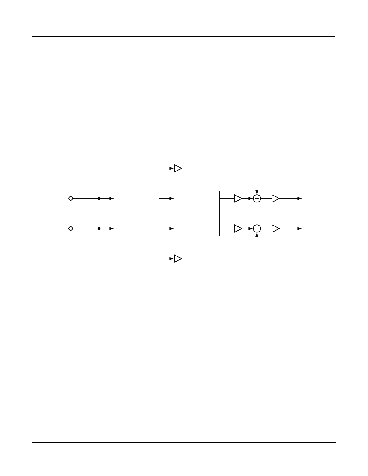
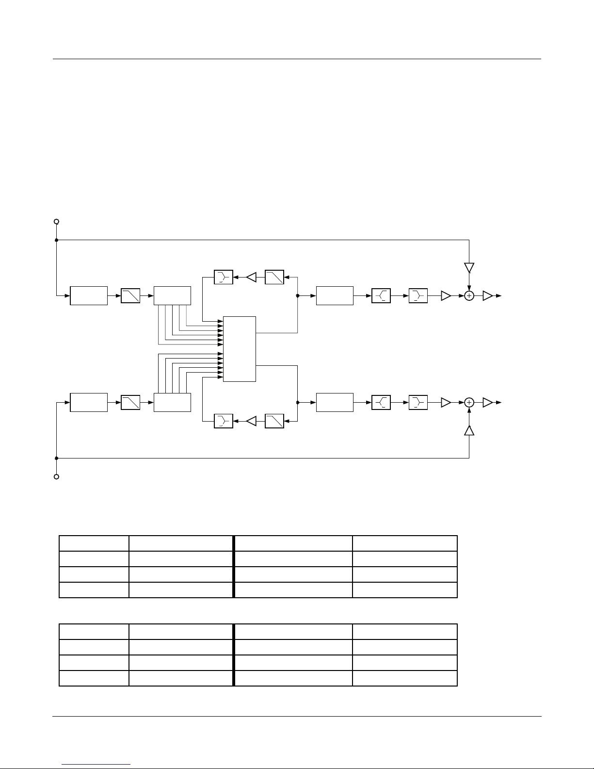
MiniVerb is a versatile stereo reverb which is found in many combination algorithms, but is equally useful on its
own because of its small size. The main control for this effect is the Room Type parameter. Room Type changes the
structure of the algorithm to simulate many carefully crafted room types and sizes. Spaces characterized as booths,
small rooms, chambers, halls and large spaces can be selected.
Dry
L Input
R Input
Each Room Type incorporates different diffusion, room size and reverb density settings. The Room Types were
designed to sound best when Diff Scale, Size Scale and Density are set to the default values of 1.00x. If you want a
reverb to sound perfect immediately, set the Diff Scale, Size Scale and Density parameters to 1.00x, pick a Room
Type and youÕll be on the way to a great sounding reverb. But if you want to experiment with new reverb flavors,
changing the scaling parameters away from 1.00x can cause a subtle (or drastic!) coloring of the carefully crafted
Room Types.
Diffusion characterizes how the reverb spreads the early reflections out in time. At very low settings of Diff Scale,
the early reflections start to sound quite discrete, and at higher settings the early reflections are seamless. Density
controls how tightly the early reflections are packed in time. Low Density settings have the early reflections
grouped close together, and higher values spread the reflections for a smoother reverb.
L PreDelay
Miniverb
Core
R PreDelay
Dry
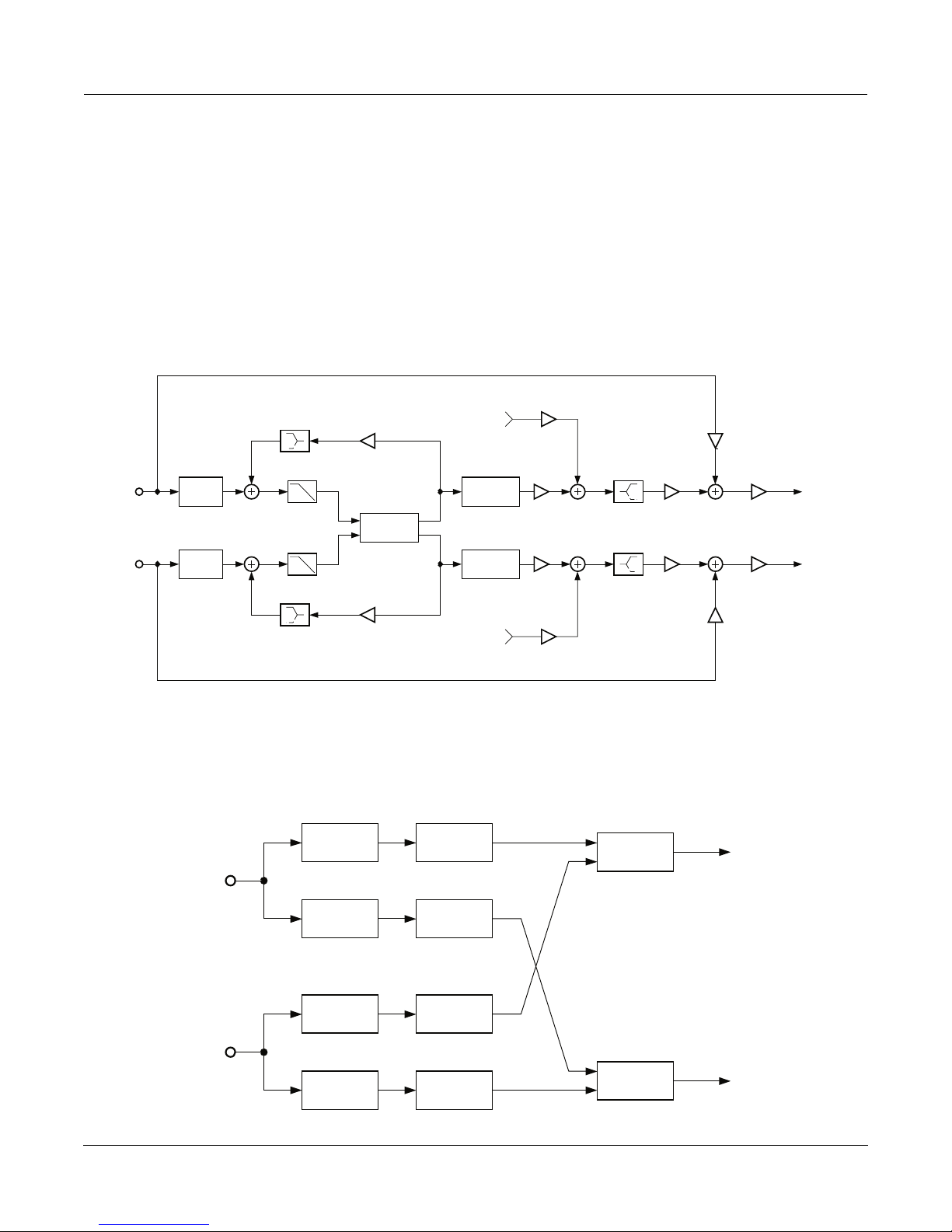
Simplified block diagram of MiniVerb
L Output
Wet Out Gain
R Output
Algorithm Reference-2
Page 3
FXAlg #1: MiniVerb ¥ FXAlg #2: Dual MiniVerb
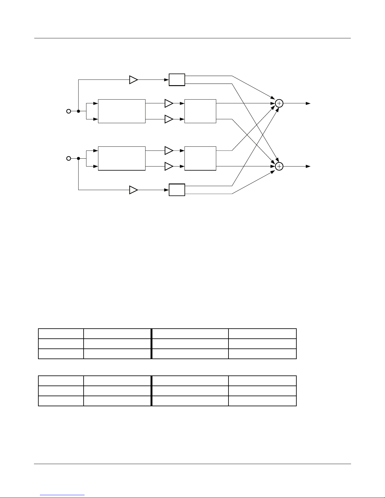
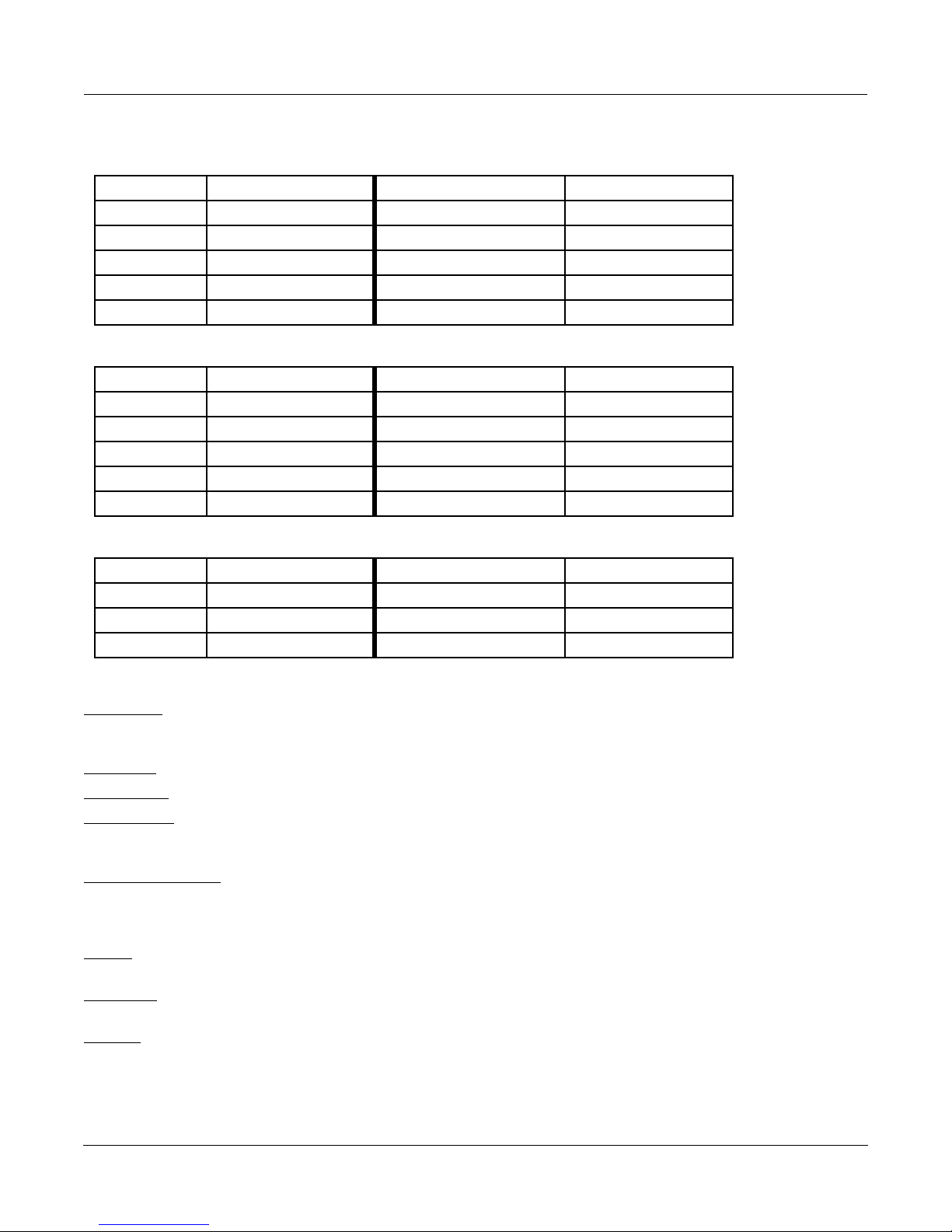
L Input
R Input
Dry
MiniVerb Balance
MiniVerb
Dry
Wet
Wet
Pan
L Output
Balance
R Output
Pan
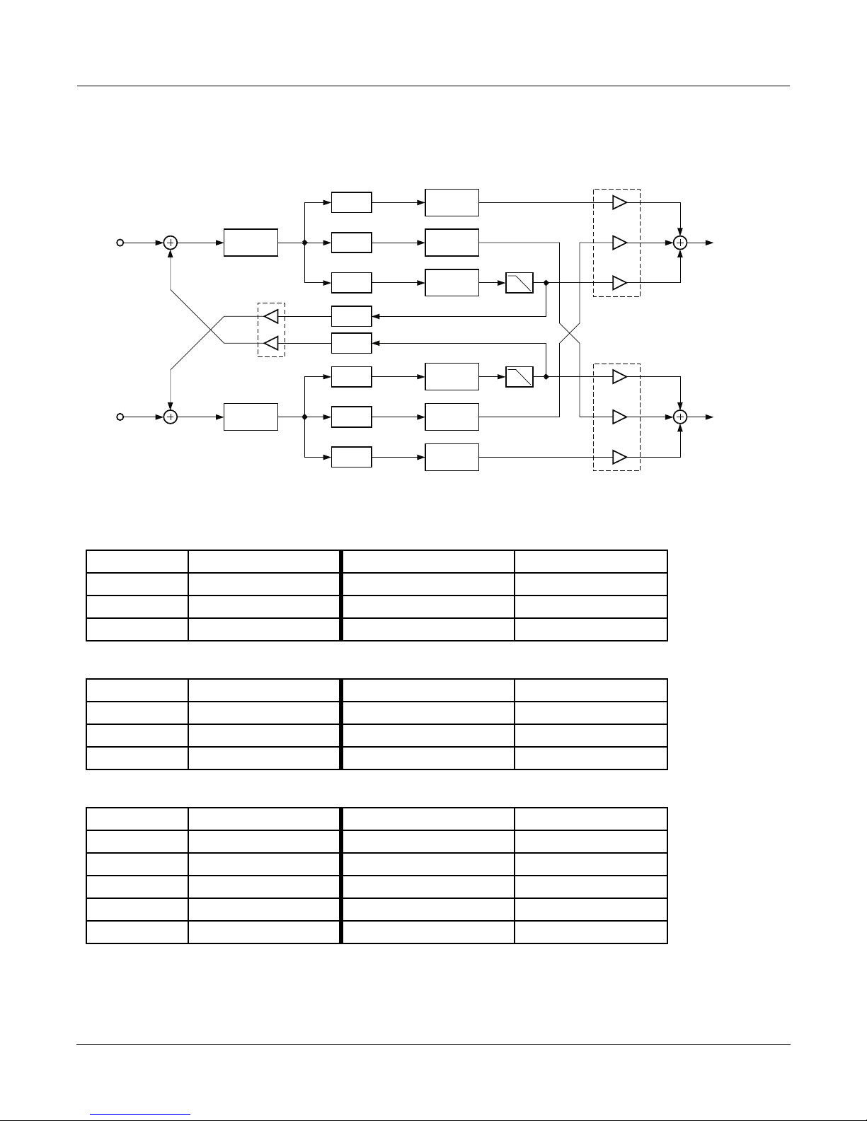
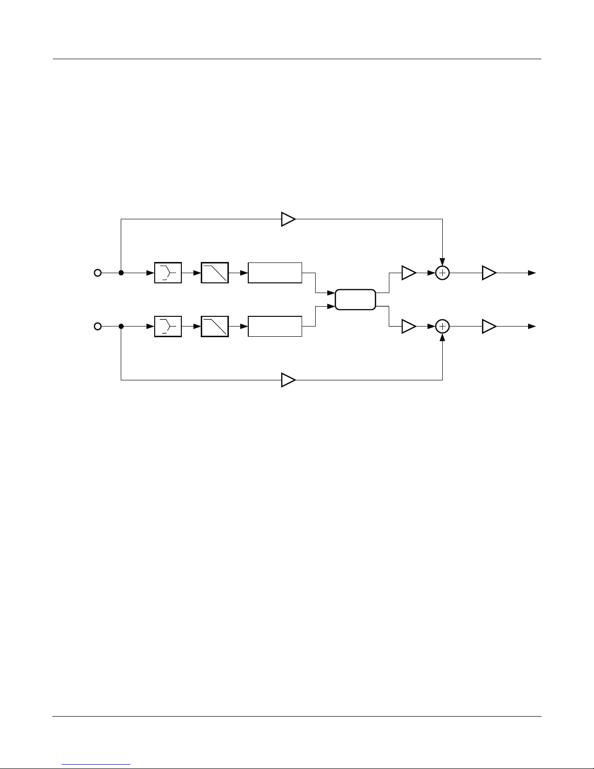
Simplified block diagram of Dual MiniVerb
Dual MiniVerb has a full MiniVerb, including Wet/Dry, Pre Delay and Out Gain controls, dedicated to each of the
left and right channels. The two blocks in the diagram above labeled ÒMiniVerbÓ contain a complete copy of the
MiniVerb on the previous page. Dual MiniVerb gives you independent reverbs on both channels which has obvious
benefits for mono material. With stereo material, any panning or image placement can be maintained, even in the
reverb tails. This is pretty unusual behavior for a reverb, since even real halls will rapidly delocalize acoustic images
in the reverberance. Since maintaining image placement in the reverberation is so unusual, you will have to
carefully consider whether it is appropriate for your particular situation. To use Dual MiniVerb to maintain stereo
signals in this manner, set the reverb parameters for both channels to the same values. The Dry Pan and Wet Bal
parameters should be fully left (-100%) for the left MiniVerb and fully right (100%) for the right MiniVerb.
Parameters (MiniVerb):
PAGE 1
Wet/Dry 0 to 100%wet Out Gain Off, -79.0 to 24.0 dB
Rvrb Time 0.5 to 30.0 s, Inf HF Damping 16 to 25088 Hz
L Pre Dly 0 to 620 ms R Pre Dly 0 to 620 ms
PAGE 2
Room Type Hall1 Diff Scale 0.00 to 2.00x
Size Scale 0.00 to 4.00x
Density 0.00 to 4.00x
Algorithm Reference-3
Page 4
FXAlg #1: MiniVerb ¥ FXAlg #2: Dual MiniVerb
Parameters (Dual MiniVerb):
PAGE 1
L Wet/Dry 0 to 100%wet R Wet/Dry 0 to 100%wet
L Out Gain Off, -79.0 to 24.0 dB R Out Gain Off, -79.0 to 24.0 dB
L Wet Bal -100 to 100% R Wet Bal -100 to 100%
L Dry Pan -100 to 100% R Dry Pan -100 to 100%
PAGE 2
L RoomType Hall1
L RvrbTime 0.5 to 30.0 s, Inf
L Diff Scl 0.00 to 2.00x L Density 0.00 to 4.00x
L Size Scl 0.00 to 4.00x L HF Damp 16 to 25088 Hz
L PreDlyL 0 to 620 ms L PreDlyR 0 to 620 ms
PAGE 3
R RoomType Hall1
R RvrbTime 0.5 to 30.0 s, Inf
R Diff Scl 0.00 to 2.00x R Density 0.00 to 4.00x
R Size Scl 0.00 to 4.00x R HF Damp 16 to 25088 Hz
R PreDlyL 0 to 620 ms R PreDlyR 0 to 620 ms
Wet/Dry A simple mix of the reverb sound with the dry sound.
Out Gain The overall gain or amplitude at the output of the effect.
Rvrb Time The reverb time displayed is accurate for normal settings of the other parameters (HF
Damping = 25088kHz, and Diff Scale, Room Scale and Density = 1.00x). Changing Rvrb
Time to Inf creates an inÞnitely sustaining reverb.
HF Damping Reduces high-frequency components of the reverb above the displayed cutoff frequency.
Removing higher reverb frequencies can often make rooms sound more natural.
L/R Pre Dly The delay between the start of a sound and the output of the Þrst reverb reßections from
that sound. Longer pre-delays can help make larger spaces sound more realistic. Longer
times can also help improve the clarity of a mix by separating the reverb signal from the
dry signal, so the dry signal is not obscured. Likewise, the wet signal will be more
audible if delayed, and thus you can get by with a dryer mix while maintaining the same
subjective wet/dry level.
Room Type Changes the conÞguration of the reverb algorithm to simulate a wide array of carefully
designed room types and sizes. This parameter effectively allows you to have several
different reverb algorithms only a parameter change away. Smaller Room Types will
sound best with shorter Rvrb Times, and vice versa. (Note that since this parameter
changes the structure of the reverb algorithm, you donÕt want to assign it a KDFX
Modulation that will change it in real time.)
Diff Scale A multiplier which affects the diffusion of the reverb. At 1.00x, the diffusion will be the
normal, carefully-adjusted amount for the current Room Type. Altering this parameter
will change the diffusion from the preset amount.
Algorithm Reference-4
Page 5

FXAlg #1: MiniVerb ¥ FXAlg #2: Dual MiniVerb
Size Scale A multiplier which changes the size of the current room. At 1.00x, the room will be the
normal, carefully-tweaked size of the current Room Type. Altering this parameter will
change the size of the room, and thus will cause a subtle coloration of the reverb (since
the roomÕs dimensions are changing).
Density A multiplier which affects the density of the reverb. At 1.00x, the room density will be
the normal, carefully-set amount for the current Room Type. Altering this parameter will
change the density of the reverb, which may color the room slightly.
Wet Bal In Dual MiniVerb, two mono signals (left and right) are fed into two separate stereo
reverbs. If you center the wet balance (0%), the left and right outputs of the reverb will
be sent to the Þnal output in equal amounts. This will add a sense of spaciousness.
Algorithm Reference-5
Page 6
FXAlg #3: Gated MiniVerb
FXAlg #3: Gated MiniVerb
A reverb and gate in series
Allocation Units: 2
This algorithm is a small reverb followed by a gate. The main control for the reverb is the Room Type parameter.
Room Type changes the structure of the algorithm to simulate many carefully crafted room types and sizes. Spaces
characterized as booths, small rooms, chambers, halls and large spaces can be selected. See the previous section
(FXAlg #1-2) for details on the reverb.
The gate turns the output of the reverb on and off based on the amplitude of the input signal. One or both input
channels is used to control whether the switch is on (gate is open) or off (gate is closed). This on/off control is called
Òside chainÓ processing. You select which of the two input channels or both is used for side chain processing. When
you select both channels, the sum of the left and right input amplitudes is used.
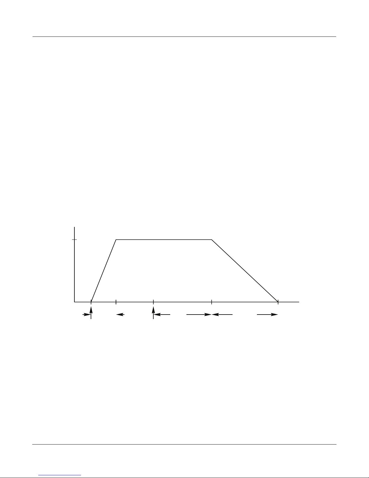
The gate is opened when the side chain amplitude rises above a level that you specify with the Threshold parameter.
The gate will stay open for as long as the side chain signal is above the threshold. When the signal drops below the
threshold, the gate will remain open for the time set by the Gate Time parameter. At the end of the Gate Time, the
gate closes. When the signal rises above threshold, it opens again. What is happening is that the gate timer is being
constantly retriggered while the signal is above threshold.
1
0
attack
time
signal rises
above threshold
If Gate Duck is turned on, then the behavior of the gate is reversed. The gate is open while the side chain signal is
below threshold, and it closes when the signal rises above threshold.
signal falls
below threshold
gate
time
Gate Behavior
release
time
If the gate opened and closed instantaneously, you would hear a large digital click, like a big knife switch was being
thrown. Obviously thatÕs not a good idea, so Gate Atk (attack) and Gate Rel (release) parameters are used to set the
times for the gate to open and close. More precisely, depending on whether Gate Duck is off or on, Gate Atk sets
how fast the gate opens or closes when the side chain signal rises above the threshold. The Gate Rel sets how fast
the gate closes or opens after the gate timer has elapsed.
The Signal Dly parameter delays the signal being gated, but does not delay the side chain signal. By delaying the
main signal relative to the side chain signal, you can open the gate just before the main signal rises above threshold.
ItÕs a little like being able to pick up the telephone before it rings!
Algorithm Reference-6
Page 7
FXAlg #3: Gated MiniVerb
Parameters:
PAGE 1
Wet/Dry 0 to 100%wet Out Gain Off, -79.0 to 24.0 dB
Rvrb Time 0.5 to 30.0s, Inf HF Damping 16 to 25088 Hz
L Pre Dly 0 to 620ms R Pre Dly 0 to 620 ms
PAGE 2
Room Type Hall1 Diff Scale 0.00 to 2.00x
Size Scale 0.00 to 4.00x
Density 0.00 to 4.00x
PAGE 3
Gate Thres -79.0 to 0.0 dB Gate Time 0 to 3000 ms
Gate Duck In or Out Gate Atk 0.0 to 228.0 ms
Gate Rel 0 to 3000 ms
GateSigDly 0.0 to 25.0 ms
Reduction
-dB 60 40 * 16 * 8 4 0
Wet/Dry A simple mix of the reverb sound with the dry sound. When set fully dry (0%), the gate
is still active.
Out Gain An overall level control of the effectÕs output (applied after the gate).
Gate Thres The input signal level in dB required to open the gate (or close the gate if Gate Duck is
on).
Gate Duck When set to ÒOffÓ, the gate opens when the signal rises above threshold and closes when
the gate time expires. When set to ÒOnÓ, the gate closes when the signal rises above
threshold and opens when the gate time expires.
Gate Time The time in seconds that the gate will stay fully on after the signal envelope rises above
threshold. The gate timer is started or restarted whenever the signal envelope rises
above threshold.
Gate Atk The attack time for the gate to ramp from closed to open (reverse if Gate Duck is on)
after the signal rises above threshold.
Gate Rel The release time for the gate to ramp from open to closed (reverse if Gate Duck is on)
after the gate timer has elapsed.
Signal Dly The delay in milliseconds (ms) of the reverb input signal relative to the side chain signal.
By delaying the reverb signal, the gate can be opened before the reverb signal rises
above the gating threshold.
For descriptions of the other parameters, see the previous section, FXAlgs #1-2.
Algorithm Reference-7
Page 8

FXAlgs #4-11: Classic ¥ TQ ¥ Diffuse ¥ Omni reverbs
FXAlgs #4-11:
Classic ¥ TQ ¥ Diffuse ¥ Omni reverbs
FXAlg #4: Classic Place
FXAlg #5: Classic Verb
FXAlg #6: TQ Place
FXAlg #7: TQ Verb
FXAlg #8: Diffuse Place
FXAlg #9: Diffuse Verb
FXAlg #10: OmniPlace
FXAlg #11: OmniVerb
More Complex Reverb algorithms
Allocation Units: ÒClassicÓ 2; others 3
This set of 2 and 3 PAU sized algorithms can be divided into 2 groups: Verb and Place. Verb effects allow user
friendly control over medium to large spaces. Their decay times are controlled by Rvrb Time or LateRvbTim
parameters, and Room Types range from rooms to large areas. Place algorithms on the other hand are optimized
for small spaces. Decay time is controlled by the Absorption parameter, and Room Types offers several booths.
Each of these reverb algorithms combines several components: a diffuser, an injector, predelay, an ambience
generator with feedback, and various filters. These components provide sonic building blocks for both the early
reflection portions and the body of the reverb.
The ambience generator is the heart of each reverb algorithm and creates most of the ÔlateÕ reverb in algorithms with
an Early Reflections circuit. It is comprised of a complex arrangement of delay lines to disperse the sound. By using
feedback in conjunction with the ambience generator, a reverb tail is produced. The length of this reverb tail is
controlled by the Rvrb Time parameter in the ÒVerbÓ algorithms, or the Absorption parameter in ÒPlaceÓ
algorithms.
In order to create reverbs that are smoother and richer, some of the delays in the ambience generator are moved by
LFOs. The LFOs are adjusted by using the LFO Rate and LFO Depth controls. When used subtly, unwanted artifacts
such as flutter and ringing that are inherent in digital reverbs can be reduced.
In the feedback loop of the ambience generator are filters that further enhance the sonic properties of each reverb.
A lowpass filter is controlled by HF Damping. Its action mimics high-frequency energy being absorbed as the sound
travels around a room. A low shelving filter is controlled by LF Split and LF Time, which are used to shorten or
lengthen the decay time of low frequency energy.
At the beginning of each algorithm are diffusers. A diffuser creates an initial ÒsmearingÓ quality on input signals
usually before the signal enters the ambience generating loop. The DiffAmtScl and DiffLenScl parameters
respectively change the amount and the length of time that the sound is smeared. The Diffuse reverbs, however,
implement diffusion a little differently. See the section on Diffuse Verb and Diffuse Place below for detailed
information.
Algorithm Reference-8
Page 9

FXAlgs #4-11: Classic ¥ TQ ¥ Diffuse ¥ Omni reverbs
Some algorithms use injector mechanisms when feeding a signal into the ambience generator. An injector creates
copies of the input signal at different delay intervals and feeds each copy into the ambience generator at different
points. This results in finer control over the onset of the reverb. By tapering the amplitudes of early copies vs. late
copies, the initial build of the reverb can be controlled. Inj Build controls this taper. Negative values create a slower
build, while positive values create a faster build. Inj Spread scales the length of all the copies as a group. Inj Skew
(Omni reverbs) delays one channel relative to the other before injecting into the ambience generator. Negative
values delay the left side while positive values delay the right side. Inj LP controls the cutoff frequency of a 1 pole
(6dB/oct) lowpass filter associated with the injector.
Predelay can give the illusion that a space is more voluminous. Separate control over left and right predelay is
provided which can be used to de-correlate the center image, increasing reverb envelopment.
In addition to filters inside the ambience feedback loop, there also may be filters placed at the output of the reverb
including a low shelf, high shelf, and/or lowpass.
Algorithms that utilize Early Reflection circuits use a combination of delays, diffusers, and filters to create ambience
that is sparser than the late portion of the reverb. These early reflections model the initial near-discrete echoes
rebounding directly off of near field surfaces before the reverb has a chance to become diffuse. They add realism
when emulating real rooms and halls.
The starting point when creating a new reverb preset should be the Room Type parameter. This parameter selects
the basic type of reverb. Due to the inherent complexity of reverb algorithms and the sheer number of variables
responsible for their character, the Room Type parameter provides condensed preset collections of these variables.
Each Room Type collection has been painstakingly selected by Kurzweil engineers to provide the best-sounding
combination of mutually complementary variables modeling an assortment of reverb families. When a room type
is selected, an entire incorporated set of delay lengths and diffusion settings are established within the algorithm.
By using the Size Scale, DiffAmtScl, DiffLenScl, and Inj Spread parameters, you may scale individual elements away
from their pre-defined values. When set to 1.00x, each of these elements are accurately representing their preset
values determined by the current Room Type.
Room Types with similar names in different reverb algorithms do not sound the same. For example, Hall1 in Diffuse
Verb does not sound the same as Hall1 in TQ Verb.
The Size Scale parameter scales the inherent size of the reverb chosen by Room Type. For a true representation of
the selected Room Type size, set this to 1.00x. Scaling the size below this will create smaller spaces, while larger scale
factors will create large spaces.
The InfinDecay switch is designed to override the Rvrb Time parameter and create a reverb tail with an infinite
decay time when ÔOnÕ. However, certain HF Damping settings may reduce this effect, and cause the tail to taper
away. This parameter is an excellent candidate for a KDFX Modulation, using a switch pedal as a source.
Algorithm Reference-9
Page 10
FXAlgs #4-11: Classic ¥ TQ ¥ Diffuse ¥ Omni reverbs
Classic Verb and Classic Place:
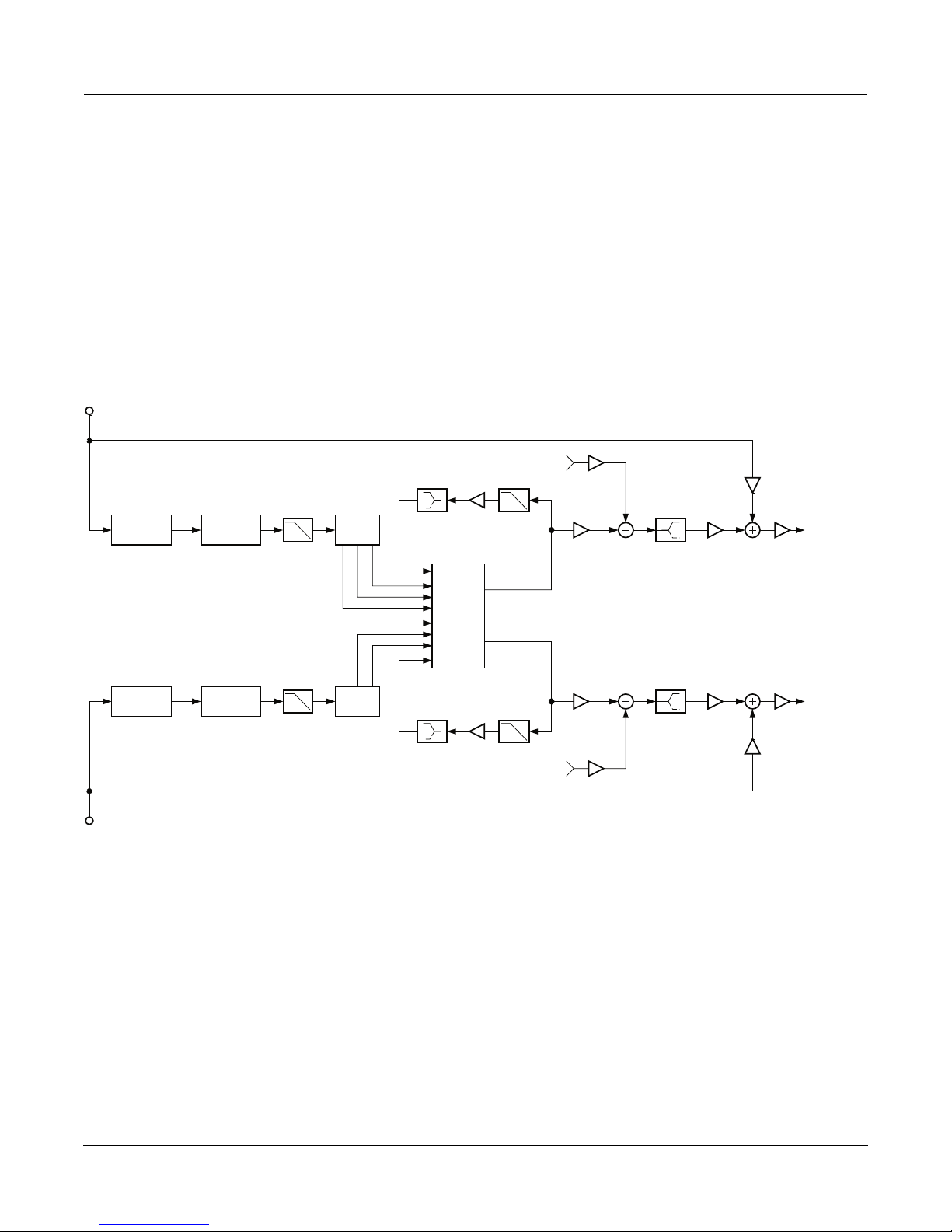
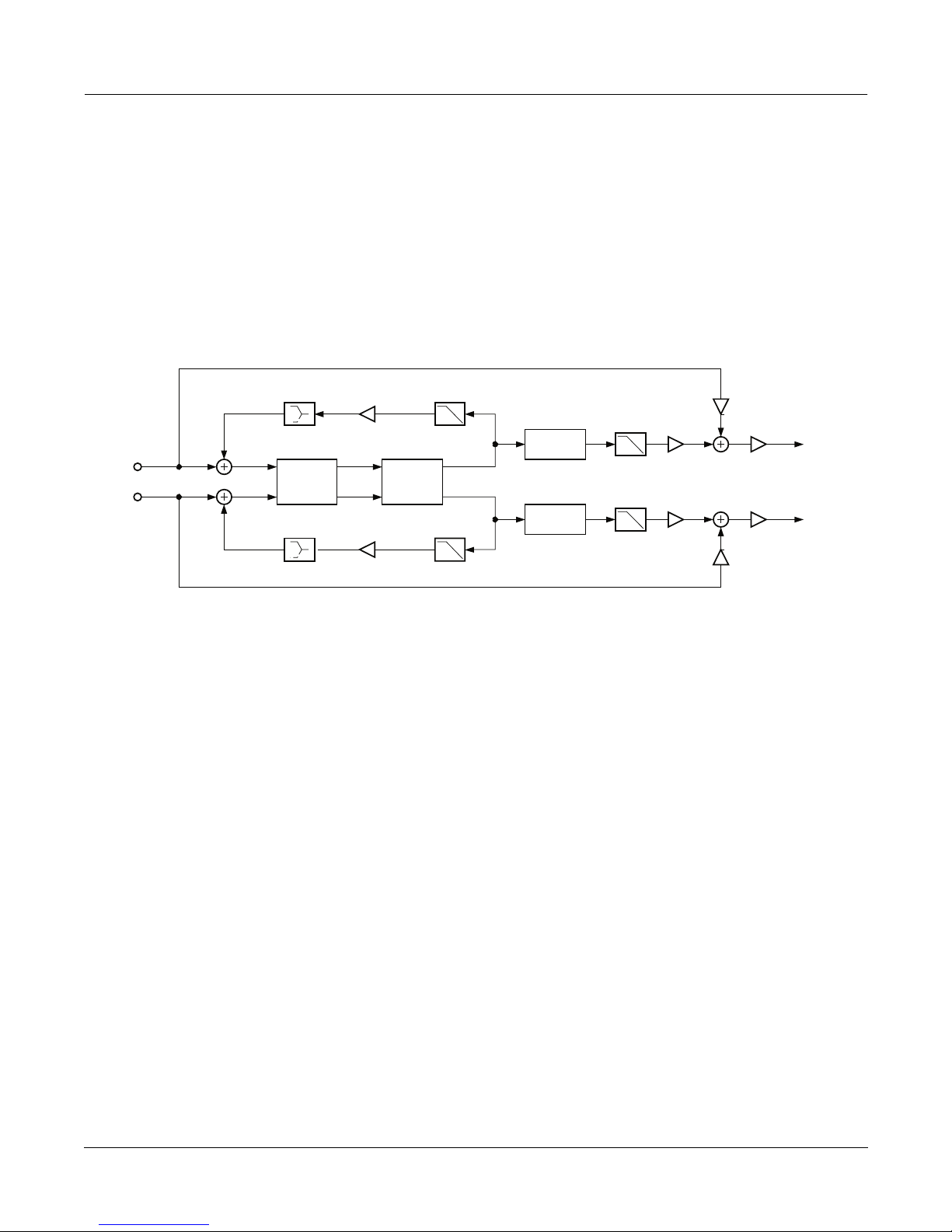
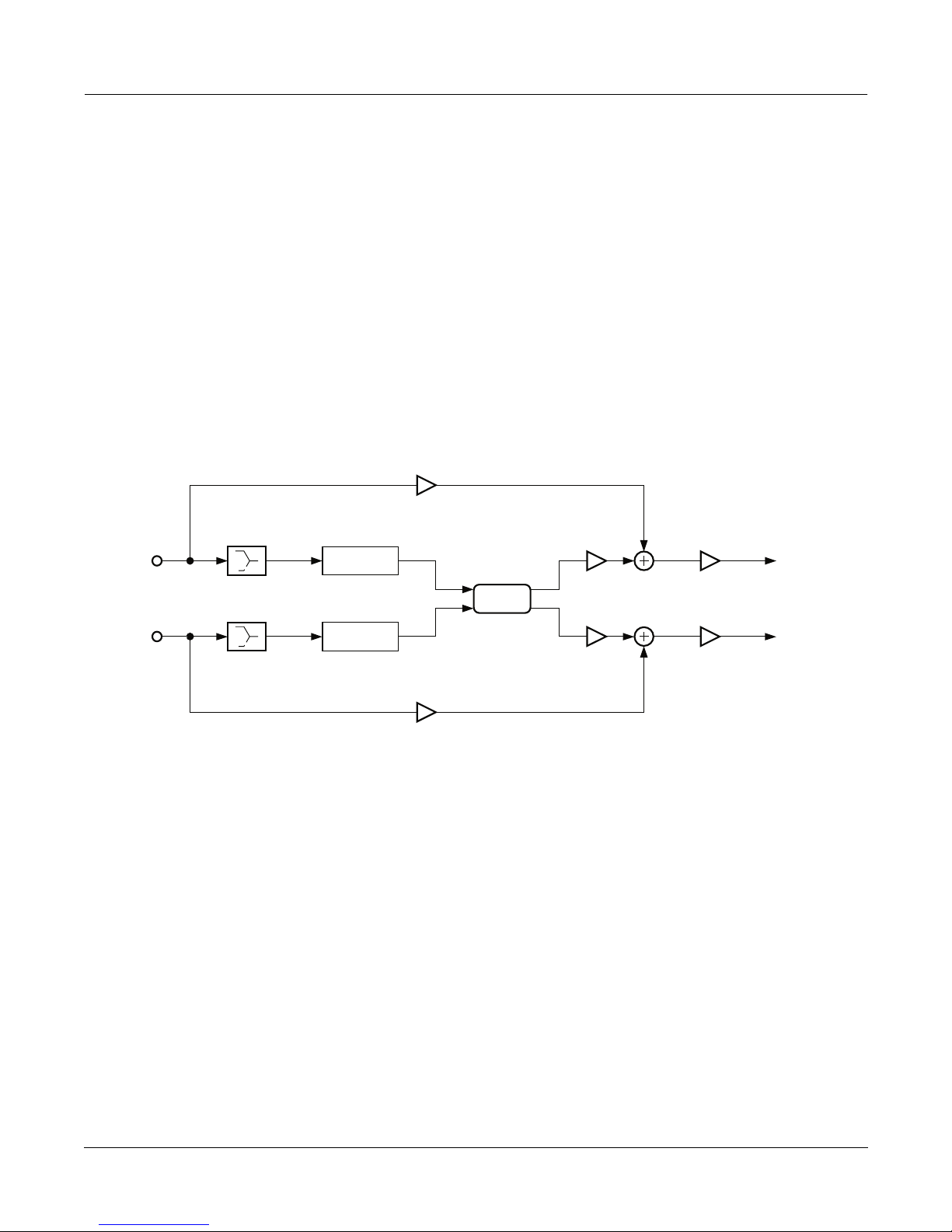
Classic reverbs are 2-PAU algorithms with early reflections. The late portion consists of an input diffuser; ambience
generator with low shelving filters, lowpass filters, and LFO moving delays; and predelay.
The early reflection portion consists of one delay per channel sent to its own output channel controlled by E Dly L
and E Dly R, and one delay per channel sent to its opposite output channel controlled be E Dly LX and E Dly RX.
Each of these delays also use a Diffuser. Diffusion lengths are separately controlled by E DifDly L, E DifDly R, E
DifDly LX, and E DifDly RX while diffusion amounts are all adjusted with E DiffAmt.
The late reverb and early reflection portions are independently mixed together with the Late Lvl and EarRef Lvl
controls. The wet signal is passed through a final high-shelving filter before being mixed with the dry signal.
L Input
R Input
DiffAmtScl
DiffLenScl
Diffusor
DiffAmtScl
DiffLenScl
Diffusor
LF Mult
HF Damping
HF Damping
LF Mult
Rvrb Time
Absorption
Ambience
Rvrb Time
Absorption
L ER Output
L Pre Dly
R Pre Dly
R ER Output
Late
Lvl
Late
Lvl
Signal flow of Classic Verb and Classic Place
E DfDlyScl
E DiffAmt
(Apply to all Diffusors)
E DifDlyL
E Dly L
Diffusor
EarRef Lvl
EarRef Lvl
Treble
Treble
Blend
Dry
Wet
L Output
Out Gain
R Output
Wet
Dry
L ER Output
L Input
E Dly LX
E Dly RX
R Input
Early reflection portion of Classic Verb and Classic Place
Algorithm Reference-10
E Dly R
E DifDlyLX
Diffusor
E DifDlyR
Diffusor
E DifDlyRX
Diffusor
E Blend X
E Blend X
Blend
R ER Output
Page 11
FXAlgs #4-11: Classic ¥ TQ ¥ Diffuse ¥ Omni reverbs
PAGE 1 (Classic Verb)
Wet/Dry -100 to 100% Out Gain Off; -79.0 to 24.0 dB
Rvrb Time 0.00 to 60.00 s EarRef Lvl -100 to 100%
HF Damping 0 to 25088 Hz Late Lvl -100 to 100%
L Pre Dly 0.0 to 230.0 ms R Pre Dly 0.0 to 230.0 ms
PAGE 1 (Classic Place)
Wet/Dry -100 to 100% Out Gain Off; -79.0 to 24.0 dB
Absorption 0 to 100% EarRef Lvl -100 to 100%
HF Damping 0 to 25088 Hz Late Lvl -100 to 100%
L Pre Dly 0.0 to 230.0 ms R Pre Dly 0.0 to 230.0 ms
PAGE 2 (Classic Verb)
Room Type Hall1, ... DiffAmtScl 0.00 to 2.00 x
Size Scale 0.01 to 2.00x DiffLenScl 0.00 to 2.00 x
InfinDecay On or Off LFO Rate 0.01 to 10.00 Hz
LFO Depth 0.0 to 100.0 ct
TrebShlf F 16 to 25088 Hz LF Split 16 to 25088 Hz
TrebShlf G -79.0 to 24.0 dB LF Time 0.50 to 1.50 x
PAGE 2 (Classic Place)
Room Type Booth1, ... DiffAmtScl 0.00 to 2.00 x
Size Scale 0.01 to 2.00x DiffLenScl 0.00 to 2.00 x
LFO Rate 0.01 to 10.00 Hz
LFO Depth 0.0 to 100.0 ct
TrebShlf F 16 to 25088 Hz LF Split 16 to 25088 Hz
TrebShlf G -79.0 to 24.0 dB LF Time 0.50 to 1.50 x
PAGE 3
E DfDlyScl 0.00 to 2.00 x E X Blend 0 to 100%
E DiffAmt -100 to 100%
E Dly L 0.0 to 720.0 ms E Dly R 0.0 to 720.0 ms
E Dly LX 0.0 to 720.0 ms E Dly RX 0.0 to 720.0 ms
E DifDlyL 0.0 to 160.0 ms E DifDlyR 0.0 to 160.0 ms
E DifDlyLX 0.0 to 230.0 ms E DifDlyRX 0.0 to 230.0 ms
Algorithm Reference-11
Page 12
FXAlgs #4-11: Classic ¥ TQ ¥ Diffuse ¥ Omni reverbs
TQ Verb and TQ Place:
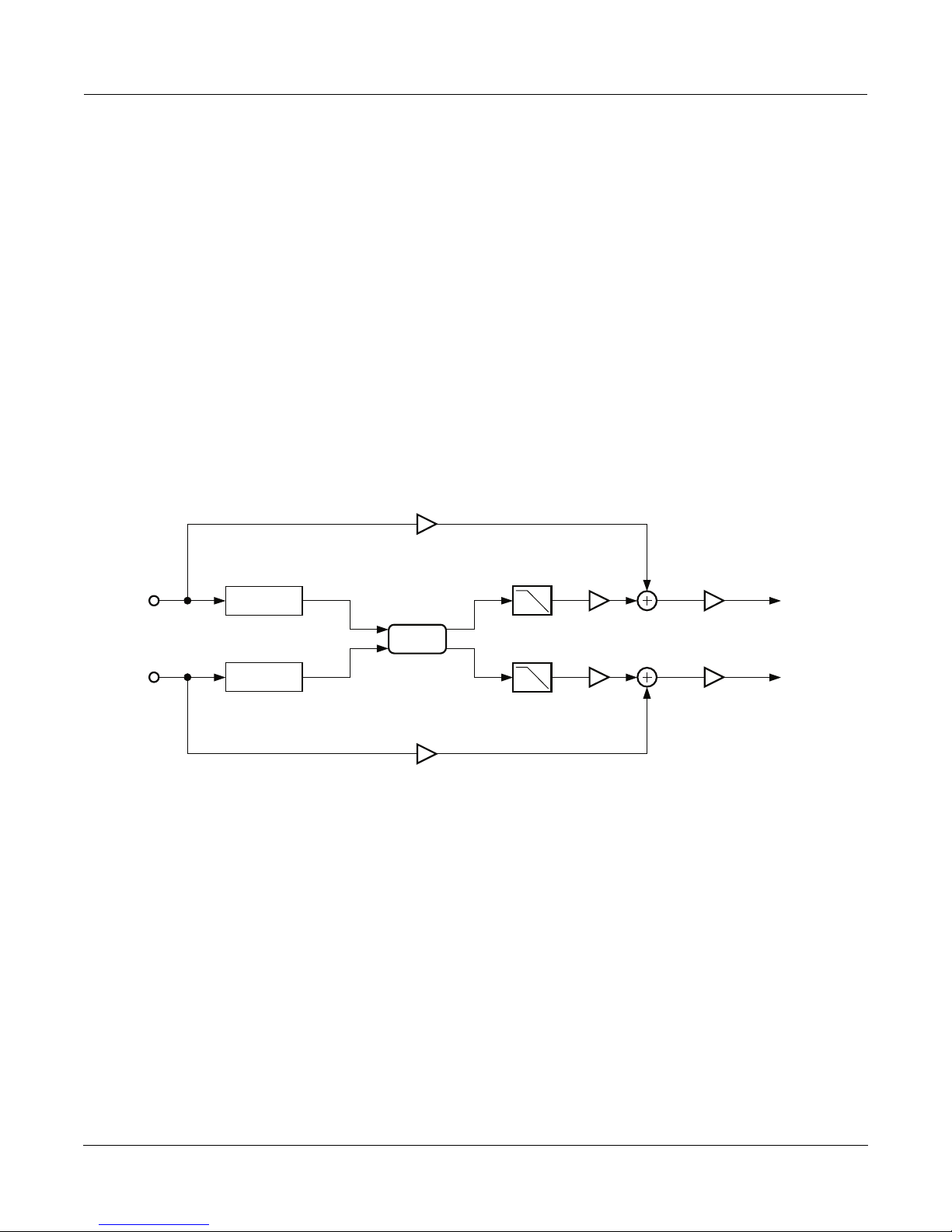
TQ reverbs are 3-PAU algorithms with early reflections. The late portion consists of an input diffuser, injector,
ambience generator with a lowpass filter, low shelving filter, and LFO moving delays, and predelay.
The early reflection portion combines a combination of delays, diffusers, and feedback. The relative delay lengths
are all fixed but are scalable with the E Dly Scl parameter. Relative diffusion lengths are also fixed, and are scalable
with the E DfLenScl parameter. Diffusion amounts are adjusted with E DiffAmt. The E Build parameter ramps the
gains associated with each delay line in a way that changes the characteristic of the onset of the early reflections.
Negative amounts create a slower onset while positive amounts create a faster onset.
The late reverb and early reflection portions are independently mixed together with the Late Lvl and EarRef Lvl
controls. The wet signal is passed through a final high shelving filter before being mixed with the dry signal.
L Input
DiffAmtScl
DiffLenScl
DiffAmtScl
DiffLenScl
R Input
Diffuser
Diffuser
L Pre Dly
R Pre Dly
Inj LP
Inj LP
InjBuild
InjSpread
Injector
Injector
InjBuild
InjSpread
Reverb Time
LF Mult
Ambience
LF Mult
Reverb Time
Absorption
Absorption
L ER Output
HF Damping
HF Damping
R ER Output
EarRef Lvl
Late Lvl
Late Lvl
EarRef Lvl
Signal flow of TQ Verb and TQ Place
Treble
Treble
Wet
Wet
Dry
Out
Gain
Out
Gain
Dry
L Output
R Output
Algorithm Reference-12
Page 13
E Dly Scl
(Applies to
All Delays)
Delay
FXAlgs #4-11: Classic ¥ TQ ¥ Diffuse ¥ Omni reverbs
Diffusor
L Input
E PreDly L
E Fdbk Amt
Delay
Delay
Diffusor
Diffusor
E Build
Delay
Delay
E Build
Diffusor
Diffusor
Diffusor
R Input
E PreDly R
Delay
Delay
Delay
Early reflection portion of TQ Verb and TQ Place
PAGE 1 (TQ Verb)
Wet/Dry -100 to 100% Out Gain Off; -79.0 to 24.0 dB
Rvrb Time 0.00 to 60.00 s EarRef Lvl -100 to 100%
HF Damping 0 to 25088 Hz Late Lvl -100 to 100%
L Pre Dly 0.0 to 230.0 ms R Pre Dly 0.0 to 230.0 ms
L ER Output
R ER Output
PAGE 1 (TQ Place)
Wet/Dry -100 to 100% Out Gain Off; -79.0 to 24.0 dB
Absorption 0 to 100% EarRef Lvl -100 to 100%
HF Damping 0 to 25088 Hz Late Lvl -100 to 100%
L Pre Dly 0.0 to 230.0 ms R Pre Dly 0.0 to 230.0 ms
PAGE 2 (TQ Verb)
Room Type Hall1, ... TrebShlf F 16 to 25088 Hz
Size Scale 0.00 to 2.50x TrebShlf G -79.0 to 24.0 dB
InfinDecay On or Off DiffAmtScl 0.00 to 2.00 x
DiffLenScl 0.00 to 2.50 x
LF Split 16 to 25088 Hz LFO Rate 0.01 to 10.00 Hz
LF Time 0.50 to 1.50 x LFO Depth 0.0 to 100.0 ct
Algorithm Reference-13
Page 14
FXAlgs #4-11: Classic ¥ TQ ¥ Diffuse ¥ Omni reverbs
PAGE 2 (TQ Place)
Room Type Booth1, ... TrebShlf F 16 to 25088 Hz
Size Scale 0.00 to 2.50x TrebShlf G -79.0 to 24.0 dB
DiffAmtScl 0.00 to 2.00 x
DiffLenScl 0.00 to 2.50 x
LF Split 16 to 25088 Hz LFO Rate 0.01 to 10.00 Hz
LF Time 0.50 to 1.50 x LFO Depth 0.0 to 100.0 ct
PAGE 3
Inj Build -100 to 100% Inj LP 16 to 25088 Hz
Inj Spread 0.00 to 2.50 x
E DiffAmt -100 to 100% E Build -100 to 100%
E DfLenScl 0.00 to 2.50 x E Fdbk Amt -100 to 100%
E DlyScl 0.00 to 2.50 x E HF Damp 16 to 25088 Hz
E PreDlyL 0.0 to 150.0 ms E PreDlyR 0.0 to 150.0 ms
Algorithm Reference-14
Page 15
FXAlgs #4-11: Classic ¥ TQ ¥ Diffuse ¥ Omni reverbs
Diffuse Verb and Diffuse Place:
Diffuse reverbs are 3-PAU algorithms and are characterized as such because of the initial burst of diffusion inherent
in the onset of the reverb. Each of these algorithms consists of an input diffuser; ambience generator with a lowpass
filter, low shelving filter, and LFO moving delays; and predelay.
In the Diffuse reverbs, the diffuser is implemented a little differently. The diffuser is just inside the ambience
generation loop, so changes in diffusion create changes in the reverb decay. The Diffuse reverbs also offer DiffExtent
and Diff Cross parameters. DiffExtent selects one of seven arbitrary gate-time lengths of the initial diffusion burst,
while Diff Cross adjusts the combination of left and right channels that are diffused.
L Input
R Input
LF Mult
DiffExtent
Diff Cross
Diffusor Ambience
DiffAmtScl
DiffLenScl
LF Mult
LateRvbTim
Absorption
LateRvbTim
Absorption
HF Damping
HF Damping
L Pre Dly
R Pre Dly
Signal flow of Diffuse Verb and Diffuse Place
Lopass
Lopass
Dry
Wet
L Output
Out Gain
R Output
Wet
Dry
Algorithm Reference-15
Page 16
FXAlgs #4-11: Classic ¥ TQ ¥ Diffuse ¥ Omni reverbs
PAGE 1 (Diffuse Verb)
Wet/Dry -100 to 100% Out Gain Off; -79.0 to 24.0 dB
LateRvbTim 0.00 to 60.00 s
HF Damping 0 to 25088 Hz Lopass 16 to 25088 Hz
L Pre Dly 0.0 to 230.0 ms R Pre Dly 0.0 to 230.0 ms
PAGE 1 (Diffuse Place)
Wet/Dry -100 to 100% Out Gain Off; -79.0 to 24.0 dB
Absorption 0 to 100%
HF Damping 0 to 25088 Hz Lopass 16 to 25088 Hz
L Pre Dly 0.0 to 230.0 ms R Pre Dly 0.0 to 230.0 ms
PAGE 2 (Diffuse Verb)
Room Type Hall1,... DiffExtent 1 to 7 x
Size Scale 0.01 to 2.50x Diff Cross -100 to 100%
InfinDecay On or Off DiffAmtScl 0.00 to 2.00 x
DiffLenScl 0.01 to 2.50 x
LF Split 16 to 25088 Hz LFO Rate 0.01 to 10.00 Hz
LF Time 0.50 to 1.50 x LFO Depth 0.0 to 100.0 ct
PAGE 2 (Diffuse Place)
Room Type Booth1, ... DiffExtent 1 to 7 x
Size Scale 0.01 to 2.50x Diff Cross -100 to 100%
DiffAmtScl 0.00 to 2.00 x
DiffLenScl 0.01 to 2.50 x
LF Split 16 to 25088 Hz LFO Rate 0.01 to 10.00 Hz
LF Time 0.50 to 1.50 x LFO Depth 0.0 to 100.0 ct
Algorithm Reference-16
Page 17
FXAlgs #4-11: Classic ¥ TQ ¥ Diffuse ¥ Omni reverbs
OmniVerb and OmniPlace:
Omni reverbs are 3-PAU algorithms that consist of an input diffuser; injector; ambience generator with a lowpass
filter, low shelving filter, and LFO moving delays; and predelay.
The Expanse parameter adjusts the amount of reverb energy that is fed to the edges of the stereo image. A value of
0% will concentrate energy in the center of the image, while non-zero values will spread it out. Positive and negative
values will impose different characteristics on the reverb image.
At the output of the reverb are a pair each of low-shelving and high-shelving filters.
L Input
Reverb Time
LF Mult
Absorption
HF Damping
L Pre Dly
Treble
Bass
Wet
Dry
Out
Gain
L Output
DiffAmtScl
DiffLenScl
Diffuser
Lopass
Inj Build
Inj Spread
Inj Skew
Injector
Ambience
DiffAmtScl
DiffLenScl
R Input
Diffuser
Lopass
Injector R Pre Dly
Inj Build
Inj Spread
Inj Skew
LF Mult
Reverb Time
Absorption
HF Damping
Treble
Bass
Signal flow of OmniVerb and OmniPlace
PAGE 1 (OmniVerb)
Wet/Dry -100 to 100% Out Gain Off; -79.0 to 24.0 dB
Rvrb Time 0.00 to 60.00 s
HF Damping 0 to 25088 Hz Lopass 16 to 25088 Hz
L Pre Dly 0.0 to 230.0 ms R Pre Dly 0.0 to 230.0 ms
PAGE 1 (OmniPlace)
Wet/Dry -100 to 100% Out Gain Off; -79.0 to 24.0 dB
Absorption 0 to 100%
HF Damping 0 to 25088 Hz Lopass 16 to 25088 Hz
L Pre Dly 0.0 to 230.0 ms R Pre Dly 0.0 to 230.0 ms
Wet
Out
Gain
R Output
Dry
Algorithm Reference-17
Page 18
FXAlgs #4-11: Classic ¥ TQ ¥ Diffuse ¥ Omni reverbs
PAGE 2 (OmniVerb)
Room Type Hall1, ... Expanse -100 to 100%
Size Scale 0.00 to 2.50x
InfinDecay On or Off DiffAmtScl 0.00 to 2.00 x
DiffLenScl 0.00 to 4.50 x
LF Split 16 to 25088 Hz LFO Rate 0.01 to 10.00 Hz
LF Time 0.50 to 1.50 x LFO Depth 0.0 to 100.0 ct
PAGE 2 (OmniPlace)
Room Type Booth1, ... Expanse -100 to 100%
Size Scale 0.00 to 2.50x
DiffAmtScl 0.00 to 2.00 x
DiffLenScl 0.00 to 4.50 x
LF Split 16 to 25088 Hz LFO Rate 0.01 to 10.00 Hz
LF Time 0.50 to 1.50 x LFO Depth 0.0 to 100.0 ct
PAGE 3
TrebShlf F 16 to 25088 Hz
Inj Build -100 to 100% TrebShlf G -79.0 to 24.0 dB
Inj Spread 0.00 to 4.50 x BassShlf F 16 to 25088 Hz
Inj Skew -200 to 200 ms BassShlf G -79.0 to 24.0 dB
Absorption
This controls the amount of reßective material that is in the space being emulated, much
like an acoustical absorption coefÞcient. The lower the setting, the longer it will take for
the sound to die away. A setting of 0% will cause an inÞnite decay time.
Rvrb Time Adjusts the basic decay time of the late portion of the reverb.
LateRvbTim Adjusts the basic decay time of the late portion of the reverb after diffusion.
HF Damping This controls the amount of high frequency energy that is absorbed as the reverb decays.
The values set the cutoff frequency of the 1-pole (6dB/oct) lowpass Þlter within the
reverb feedback loop.
L Pre Dly, R Pre Dly These control the amount that each channel of the reverb is delayed relative to the dry
signal. Setting different lengths for both channels can de-correlate the center portion of
the reverb image and make it seem wider. This only affects the late reverb in algorithms
that have early reßections.
Lopass Controls the cutoff frequency of a 1-pole (6dB/oct) lowpass Þlter at the output of the
reverb. This only affects the late reverb in algorithms that have early reßections.
EarRef Lvl Adjusts the mix level of the early reßection portion of algorithms offering early
reßections.
Late Lvl Adjusts the mix level of the late reverb portion of algorithms offering early reßections.
Algorithm Reference-18
Page 19

FXAlgs #4-11: Classic ¥ TQ ¥ Diffuse ¥ Omni reverbs
Room Type This parameter selects the basic type of reverb being emulated, and should be the
starting point when creating your own reverb presets. Due to the inherent complexity of
reverb algorithms and the sheer number of variables responsible for their character, the
Room Type parameter provides condensed preset collections of these variables. Each
Room Type preset has been painstakingly selected by Kurzweil engineers to provide the
best sounding collection of mutually complementary variables modeling an assortment
of reverb families. When a room type is selected, an entire incorporated set of delay
lengths and diffusion settings are established within the algorithm. By using the Size
Scale, DiffAmtScl, DiffLenScl, and Inj Spread parameters, you may scale individual
elements away from their preset value. When set to 1.00x, each of these elements is
accurately representing its preset value determined by the current Room Type.
Room Types with similar names in different reverb algorithms do not sound the same.
For example, Hall1 in Diffuse Verb does not sound the same as Hall1 in TQ Verb.
Size Scale This parameter scales the inherent size of the reverb chosen by Room Type. For a true
representation of the selected Room Type size, set this to 1.00x. Scaling the size below
this will create smaller spaces, while larger scale factors will create large spaces.
InÞnDecay Found in ÒVerbÓ algorithms. When turned ÒOnÓ, the reverb tail will decay indeÞnitely.
However, certain HF Damping settings may reduce this effect, and cause the tail to taper
away. When turned ÒOffÓ, the decay time is determined by the ÒRvrb TimeÓ or
ÒLateRvbTimÓ parameters. This parameter is an excellent candidate for a KDFX
Modulation, using a switch pedal as a source.
LF Split Used in conjunction with LF Time. This controls the upper-frequency limit of the low-
frequency decay time multiplier. Energy below this frequency will decay faster or slower
depending on the LF Time parameter.
LF Time Used in conjunction with LF Split. This modiÞes the decay time of the energy below the
LF Split frequency. A setting of 1.00x will make low-frequency energy decay at the rate
determined by the decay time. Higher values will cause low-frequency energy to decay
slower, and lower values will cause it to decay more quickly.
TrebShlf F Adjusts the frequency of a high-shelving Þlter at the output of the late reverb.
TrebShlf G Adjusts the gain of a high-shelving Þlter at the output of the late reverb.
BassShlf F Adjusts the frequency of a low-shelving Þlter at the output of the late reverb.
BassShlf G Adjusts the gain of a low-shelving Þlter at the output of the late reverb.
DiffAmtScl Adjusts the amount of diffusion at the onset of the reverb. For a true representation of
the selected Room Type diffusion amount, set this to 1.00x.
DiffLenScl Adjusts the length of the diffusion at the onset of the reverb. For a true representation of
the selected Room Type diffusion length, set this to 1.00x.
DiffExtent Adjust the onset diffusion duration. Higher values create longer diffuse bursts at the
onset of the reverb.
Diff Cross Adjusts the onset diffusion cross-coupling character. Although subtle, this parameter
bleeds left and right channels into each other during onset diffusion, and also in the
body of the reverb. 0% setting will disable this. Increasing this value in either the
positive or negative direction will increase its effect.
Expanse Amount of late reverb energy biased toward the edges of the stereo image. A setting of
0% will bias energy towards the center. Moving away from 0% will bias energy towards
the sides. Positive and negative values will have a different character.
Algorithm Reference-19
Page 20

FXAlgs #4-11: Classic ¥ TQ ¥ Diffuse ¥ Omni reverbs
LFO Depth Adjusts the detuning depth in cents caused by a moving reverb delay line. Moving delay
lines can imitate voluminous ßowing air currents and reduce unwanted artifacts like
ringing and ßutter when used properly. Depth settings under 1.5ct with LFO Rate
settings under 1.00Hz are recommended for modeling real spaces. High depth settings
can create chorusing qualities, which wonÕt be suitable for real acoustic spaces, but can
nonetheless create interesting effects. Instruments that have little or no inherent pitch
ßuctuation (like piano) are much more sensitive to this LFO than instruments that
normally have a lot of vibrato (like voice) or non-pitched instruments (like snare drum).
LFO Rate Adjusts the rate at which the moving reverb delay lines move.
Inj Build Used in conjunction with Inj Spread, this adjusts the envelope of the onset of the reverb.
SpeciÞcally, it tapers the amplitudes of a series of delayed signals injected into the body
of the reverb. Values above 0% will produce a faster build, while values below 0% will
cause the build to be more gradual.
ead Used in conjunction with Inj Build, this scales the length of the series of delays injected
Inj Spr
into the body of the reverb. For a true representation of the selected Room Type injector
spread, set this to 1.00x.
Inj LP This adjusts the cutoff frequency of a 1 pole (6dB/oct) lowpass Þlter applied to the signal
being injected into the body of the reverb.
Inj Skew Adjusts the amount of delay applied to either the left or right channel of the reverb
injector. Positive values delay the right channel while negative values delay the left
channel.
E DiffAmt Adjusts the amount of diffusion applied to the early reßection network.
E DfLenScl Adjusts the length of diffusion applied to the early reßection network. This is inßuenced
by E PreDlyL and E PreDlyR.
E Dly Scl Scales the delay lengths inherent in the early reßection network.
E Build Adjusts the envelope of the onset of the early reßections. Values above 0% will create a
faster attack while values below 0% will create a slower attack.
E Fdbk Amt Adjusts the amount of the output of an early reßection portion that is fed back into the
input of the opposite channel in front of the early pre-delays. Overall, it lengthens the
decay rate of the early reßection network. Negative values polarity-invert the feedback
signal.
E HF Damp This adjusts the cutoff frequency of a 1-pole (6dB/oct) lowpass Þlter applied to the early
reßection feedback signal.
E PreDlyL, E PreDlyR Adjusts how much the early reßections are delayed relative to the dry signal. These are
independent of the late reverb predelay times, but will inßuence E Dly Scl.
E Dly L, E Dly R Adjusts the left and right early reßection delays fed to the same output channels.
E Dly LX, E Dly RX Adjusts the left and right early reßection delays fed to the opposite output channels.
E DifDlyL, E DifDlyR Adjusts the diffusion delays of the diffusers on delay taps fed to the same output
channels.
E DifDlyLX, E DifDlyRX Adjusts the diffusion delays of the diffusers on delay taps fed to the opposite output
channels.
E X Blend Adjusts the balance between early reßection delay tap signals with diffusers fed to their
same output channel, and those fed to opposite channels. 0% allows only delay taps
being fed to opposite output channels to be heard, while 100% allows only delay taps
going to the same channels to be heard.
Algorithm Reference-20
Page 21
FXAlg #12: Panaural Room
FXAlg #12: Panaural Room
Room reverberation algorithm
Allocation Units: 3
The Panaural Room reverberation is implemented using a special network arrangement of many delay lines that
guarantees colorless sound. The reverberator is inherently stereo with each input injected into the ÒroomÓ at
multiple locations. The signals entering the reverberator first pass through a shelving bass equalizer with a range
of +/-15dB. To shorten the decay time of high frequencies relative to mid frequencies, lowpass filters controlled by
HF Damping are distributed throughout the network. Room Size scales all the delay times of the network (but not
the Pre Dly or Build Time), to change the simulated room dimension over a range of 1 to 16m. Decay Time varies
the feedback gains to achieve decay times from 0.5 to 100 seconds. The Room Size and Decay Time controls are
interlocked so that a chosen Decay Time will be maintained while Room Size is varied. A two-input stereo mixer,
controlled by Wet/Dry and Out Gain, feeds the output.
Dry
L Input
R Input
PreDelay
PreDelay
Dry
Reverb
Wet
Out Gain
L Output
R Output
Simplified block diagram of Panaural Room.
The duration and spacing of the early reflections are influenced by Room Size and Build Time, while the number
and relative loudness of the individual reflections are influenced by Build Env. When Build Env is near 0 or 100%,
fewer reflections are created. The maximum number of important early reflections, 13, is achieved at a setting of
50%.
To get control over the growth of reverberation, the left and right inputs each are passed through an ÒinjectorÓ that
can extend the source before it drives the reverberator. Only when Build Env is set to 0% is the reverberator driven
in pure stereo by the pure dry signal. For settings of Build Env greater than 0%, the reverberator is fed multiple
times. Build Env controls the injector so that the reverberation begins abruptly (0%), builds immediately to a
sustained level (50%), or builds gradually to a maximum (100%). Build Time varies the injection length over a range
of 0 to 500ms. At a Build Time of 0ms, there is no extension of the build time. In this case, the Build Env control
adjusts the density of the reverberation, with maximum density at a setting of 50%. In addition to the two build
controls, there is an overall Pre Dly control that can delay the entire reverberation process by up to 500ms.
Algorithm Reference-21
Page 22

FXAlg #12: Panaural Room
Parameters:
PAGE 1
Wet/Dry 0 to 100%wet Out Gain Off, -79.0 to 24.0
Room Size 1.0 to 16.0 m
Pre Dly 0 to 500 ms Decay Time 0.5 to 100.0 s
HF Damping 16 to 25088 Hz
PAGE 2
Bass Gain -15 to 15 dB Build Time 0 to 500 ms
Build Env 0 to 100%
Wet/Dry The amount of the stereo reverberator (wet) signal relative to the original input (dry)
signal to be output. The dry signal is not affected by the Bass Gain control. The wet
signal is affected by the Bass Gain control and by all the other reverberator controls. The
balance between wet and dry signals is an extremely important factor in achieving a
good mix. Emphasizing the wet signal gives the effect of more reverberation and of
greater distance from the source.
Out Gain
Decay Time The reverberation decay time (mid-band ÒRT60Ó), the time required before the
HF Damping Adjusts lowpass Þlters in the reverberator so that high frequencies die away more
Bass Gain Shapes the overall reverberation signalÕs bass content, but does not modify the decay
Room Size Choosing an appropriate room size is very important in getting a good reverberation
Pre Dly Introducing predelay creates a gap of silence that allows the dry signal to stand out with
Build Time Similar to predelay, but more complex, larger values of Build Time slow down the
The overall output level for the reverberation effect, and controls the level for both the
wet and dry signal paths.
reverberation has died away to 60dB below its ÒrunningÓ level. Adjust decay time
according to the tempo and articulation of the music and to taste.
quickly than mid and low frequencies. This shapes the reverberation for a more natural,
more acoustically accurate sound.
time. Reduce the bass for a less muddy sound, raise it slightly for a more natural
acoustic effect.
effect. For impulsive sources, such as percussion instruments or plucked strings,
increase the size setting until discrete early reßections become audible, and then back it
off slightly. For slower, softer music, use the largest size possible. At lower settings,
Room Size leads to coloration, especially if the Decay Time is set too high.
greater clarity and intelligibility against the reverberant background. This is especially
helpful with vocal or classical music.
building up of reverberation and can extend the build-up process. Experiment with
Build Time and Build Env and use them to optimize the early details of reverberation. A
Build Time of 0ms and a Build Env of 50% is a good default setting that yields a fast
arriving, maximally dense reverberation.
Algorithm Reference-22
Page 23

FXAlg #12: Panaural Room
Build Env When Build Time has been set to greater than about 80ms, Build Env begins to have an
audible inßuence on the early unfolding of the reverberation process. For lower-density
reverberation that starts cleanly and impulsively, use a setting of 0%. For the highestdensity reverberation, and for extension of the build-up period, use a setting of 50%. For
an almost reverse reverberation, set Build Env to 100%. You can think of Build Env as
setting the position of a see-saw. The left end of the see-saw represents the driving of the
reverberation at the earliest time, the pivot point as driving the reverberation at midpoint in the time sequence, and the right end as the last signal to drive the reverberator.
At settings near 0%, the see-saw is tilted down on the right: the reverberation starts
abruptly and the drive drops with time. Near 50%, the see-saw is level and the
reverberation is repeatedly fed during the entire build time. At settings near 100%, the
see-saw is tilted down on the left, so that the reverberation is hit softly at Þrst, and then
at increasing level until the end of the build time.
Algorithm Reference-23
Page 24
FXAlg #13: Stereo Hall
FXAlg #13: Stereo Hall
A stereo hall reverberation algorithm
Allocation Units: 3
The Stereo Hall reverberation is implemented using a special arrangement of all pass networks and delay lines,
which reduces coloration and increases density. The reverberator is inherently stereo with each input injected into
the ÒroomÓ at multiple locations. To shorten the decay time of low and high frequencies relative to mid frequencies,
bass equalizers and lowpass filters, controlled by Bass Gain and by HF Damping, are placed within the network.
Room Size scales all the delay times of the network (but not the Pre Dly or Build Time), to change the simulated
room dimension over a range of 10 to 75m. Decay Time varies the feedback gains to achieve decay times from 0.5
to 100 seconds. The Room Size and Decay Time controls are interlocked so that a chosen Decay Time will be
maintained while Room Size is varied. At smaller sizes, the reverb becomes quite colored and is useful only for
special effects. A two-input stereo mixer, controlled by Wet/Dry and Out Gain, feeds the output. The Lowpass
control acts only on the wet signal and can be used to smooth out the reverb high end without modifying the reverb
decay time at high frequencies.
Dry
L Input
R Input
PreDelay
PreDelay
Reverb
Dry
Wet
L Output
Out Gain
R Output
Simplified block diagram of Stereo Hall.
Within the reverberator, certain delays can be put into a time varying motion to break up patterns and to increase
density in the reverb tail. Using the LFO Rate and Depth controls carefully with longer decay times can be beneficial.
But beware of the pitch-shifting artifacts which can accompany randomization when it is used in greater amounts.
Also within the reverberator, the Diffusion control can reduce the diffusion provided by some all pass-networks.
While the reverb will eventually reach full diffusion regardless of the Diffusion setting, the early reverb diffusion
can be reduced, which sometimes is useful to help keep the dry signal Òin the clearÓ.
The reverberator structure is stereo and requires that the dry source be applied to both left and right inputs. If the
source is mono, it should still be applied (pan centered) to both left and right inputs. Failure to drive both inputs
will result in offset initial reverb images and later ping-ponging of the reverberation. Driving only one input will
also increase the time required to build up reverb density.
Algorithm Reference-24
Page 25
FXAlg #13: Stereo Hall
To gain control over the growth of reverberation, the left and right inputs each are passed through an ÒinjectorÓ that
can extend the source before it drives the reverberator. Only when Build Env is set to 0% is the reverberator driven
in pure stereo by the pure dry signal. For settings of Build Env greater than 0%, the reverberator is fed multiple
times. Build Env controls the injector so that the reverberation begins abruptly (0%), builds immediately to a
sustained level (50%), or builds gradually to a maximum (100%). Build Time varies the injection length over a range
of 0 to 500ms. At a Build Time of 0ms, there is no extension of the build time. In this case, the Build Env control
adjusts the density of the reverberation, with maximum density at a setting of 50%. In addition to the two build
controls, there is an overall Pre Dly control that can delay the entire reverberation process by up to 500ms.
Parameters:
PAGE 1
Wet/Dry 0 to 100%wet Out Gain Off, -79.0 to 24.0 dB
Room Size 2.0 to 15.0 m Diffusion 0 to 100%
Pre Dly 0 to 500 ms Decay Time 0.5 to 100.0 ms
HF Damping 16 to 25088 Hz
PAGE 2
Bass Gain -15 to 0 dB Build Time 0 to 500 ms
Lowpass 16 to 25088 Hz Build Env 0 to 100%
LFO Rate 0.00 to 5.10 Hz
LFO Depth 0.00 to 10.20 ct
W
et/Dry The amount of the stereo reverberator (wet) signal relative to the original input (dry)
signal to be output. The dry signal is not affected by the Bass Gain control. The wet
signal is affected by the Bass Gain control and by all the other reverberator controls. The
balance between wet and dry signals is an extremely important factor in achieving a
good mix. Emphasizing the wet signal gives the effect of more reverberation and of
greater distance from the source.
Out Gain The overall output level for the reverberation effect, and controls the level for both the
wet and dry signal paths.
Decay Time The reverberation decay time (mid-band ÒRT60Ó), the time required before the
reverberation has died away to 60dB below its ÒrunningÓ level. Adjust decay time
according to the tempo and articulation of the music and to taste.
HF Damping Adjusts lowpass Þlters in the reverberator so that high frequencies die away more
quickly than mid and low frequencies. This shapes the reverberation for a more natural,
more acoustically accurate sound.
Room Size Choosing an appropriate room size is very important in getting a good reverberation
effect. For impulsive sources, such as percussion instruments or plucked strings,
increase the size setting until discrete early reßections become audible, and then back it
off slightly. For slower, softer music, use the largest size possible. At lower settings,
RoomSize leads to coloration, especially if the DecayTime is set too high.
Bass Gain Adjusts bass equalizers in the reverberator so that low frequencies die away more
quickly than mid and high frequencies. This can be used to make the reverberation less
muddy.
Algorithm Reference-25
Page 26

FXAlg #13: Stereo Hall
Lowpass Used to shape the overall reverberation signal's treble content, but does not modify the
decay time. Reduce the treble for a softer, more acoustic sound.
Pre Dly Introducing predelay creates a gap of silence that allows the dry signal to stand out with
greater clarity and intelligibility against the reverberant background. This is especially
helpful with vocal or classical music.
Build Time Similar to predelay, but more complex, larger values of BuildTime slow down the
building up of reverberation and can extend the build up process. Experiment with
BuildTime and BuildEnv and use them to optimize the early details of reverberation. A
BuildTime of 0ms and a BuildEnv of 50% is a good default setting that yields fast
arriving, natural reverberation.
Build Env When BuildTime has been set to greater than about 80ms, BuildEnv begins to have an
audible inßuence on the early unfolding of the reverberation process. For lower-density
reverberation that starts cleanly and impulsively, use a setting of 0%. For the highestdensity reverberation, and for extension of the build-up period, use a setting of 50%. For
an almost reverse reverberation, set BuildEnv to 100%. You can think of BuildEnv as
setting the position of a see-saw. The left end of the see-saw represents the driving of the
reverberation at the earliest time, the pivot point as driving the reverberation at midpoint in the time sequence, and the right end as the last signal to drive the reverberator.
At settings near 0%, the see-saw is tilted down on the right: the reverberation starts
abruptly and the drive drops with time. Near 50%, the see-saw is level and the
reverberation is repeatedly fed during the entire build time. At settings near 100%, the
see-saw is tilted down on the left, so that the reverberation is hit softly at Þrst, and then
at increasing level until the end of the build time.
LFO Rate
and LFO Depth Within the reverberator, the certain delay values can be put into a time varying
motion to break up patterns and to increase density in the reverb tail. Using the LFO
Rate and Depth controls carefully with longer decay times can be beneÞcial. But beware
of the pitch-shifting artifacts which can accompany randomization when it is used in
greater amounts.
Diffusion Within the reverberator, the Diffusion control can reduce the diffusion provided by some
of the all-pass networks. While the reverb will eventually reach full diffusion regardless
of the Diffusion setting, the early reverb diffusion can be reduced, which sometimes is
useful to help keep the dry signal "in the clear."
Algorithm Reference-26
Page 27
FXAlg #14: Grand Plate
FXAlg #14: Grand Plate
A plate reverberation algorithm
Allocation Units: 3
This algorithm emulates an EMT 140 steel plate reverberator. Plate reverberators were manufactured during the
1950s, 60s, 70s, and perhaps into the 80s. By the end of the 1980s, they had been supplanted in the marketplace by
digital reverberators, which first appeared in 1976. While a handful of companies made plate reverberators, EMT
(Germany) was the best known and most popular.
Dry
L Input
R Input
Diagram of Grand Plate reverb
A plate reverberator is generally quite heavy and large, perhaps 4 feet high by 7 feet long, and a foot thick. They
were only slightly adjustable, with controls for high frequency damping and decay time. Some were stereo
in/stereo out, others mono in/mono out.
A plate reverb begins with a sheet of plate steel suspended by its edges, leaving the plate free to vibrate. At one (or
two) points on the plate, an electromagnetic driver (sort of a small loudspeaker without a cone) is arranged to couple
the dry signal into the plate, sending sound vibrations into the plate in all directions. At one or two other locations,
a pickup is placed, sort of like a dynamic microphone whose diaphragm is the plate itself, to pick up the
reverberation.
Since the sound waves travel very rapidly in steel (faster than they do in air), and since the dimensions of the plate
are not large, the sound quickly reaches the plate edges and reflects from them. This results in a very rapid buildup of the reverberation, essentially free of early reflections and with no distinguishable gap before the onset of
reverb.
PreDelay
PreDelay
Dry
Plate
Reverb
Wet
Out Gain
Plates offered a wonderful sound of their own, easily distinguished from other reverberators in the pre-digital
reverb era, such as springs or actual ÒechoÓ chambers. Plates were bright and diffused (built up echo density)
rapidly. Curiously, when we listen to a vintage plate today, we find that the much vaunted brightness is nothing
like what we can accomplish digitally; we actually have to deliberately reduce the brightness of a plate emulation
to match the sound of a real plate. Similarly, we find that we must throttle back on the low frequency content as well.
Algorithm Reference-27
Page 28
FXAlg #14: Grand Plate
The algorithm developed for Grand Plate was carefully crafted for rapid diffusion, low coloration, freedom from
discrete early reflections, and ÒbrightnessÓ. We also added some controls that were never present in real plates: size,
predelay of up to 500ms, LF damping, lowpass roll off, and bass roll off. Furthermore, we allow a wider range of
decay time adjustment than a conventional plate. Once the algorithm was complete, we tuned it by listening to the
original EMT reverb on one channel and the Grand Plate emulation on the other. A lengthy and careful tuning of
Grand Plate (tuning at the micro detail level of each delay and gain in the algorithm) was carried out until the stereo
spread of this reverb was matched in all the time periodsÑearly, middle, and late.
The heart of this reverb is the plate simulation network, with its two inputs and two outputs. It is a full stereo
reverberation network, which means that the left and right inputs get slightly different treatment in the
reverberator. This yields a richer, more natural stereo image from stereo sources. If you have a mono source, assign
it to both inputs for best results.
The incoming left source is passed through predelay, lowpass (Lowpass), and bass-shelf (Bass Gain) blocks. The
right source is treated similarly.
There are lowpass filters (HF Damping) and high pass filters (LF Damping) embedded in the plate simulation
network to modify the decay times. The reverb network also accommodates the Room Size and Decay Time
controls.
An output mixer assembles dry and wet signals.
Parameters:
PAGE 1
Wet/Dry 0 to 100%wet Out Gain Off, -79.0 to 24.0 dB
Room Size 1.00 to 4.00 m
Pre Dly 0 to 500 ms Decay Time 0.2 to 5.0 s
HF Damping 16 to 25088 Hz LF Damping 1 to 294 Hz
PAGE 2
Lowpass 16 to 25088 Hz Bass Gain -15 to 0 dB
Wet/Dry The amount of the stereo reverberator (wet) signal relative to the original input (dry)
signal sent to the output. The dry signal is not affected by the Lowpass or Bass Gain
controls. The wet signal is affected by the Lowpass and Bass Gain controls and by all the
other reverberator controls. The balance between wet and dry signals is an extremely
important factor in achieving a good mix. Emphasizing the wet signal gives the effect of
more reverberation and of greater distance from the source.
Out Gain The overall output level for the reverberation effect and controls the level for both the
wet and dry signal paths.
Room Size Choosing an appropriate room size is very important in getting a good reverberation
effect. For impulsive sources, such as percussion instruments or plucked strings,
increase the size setting until discrete reßections become audible, and then back it off
slightly. For slower, softer music, use the largest size possible. At lower settings, Room
Size leads to coloration, especially if the Decay Time is set too high. To emulate a plate
reverb, this control is typically set to 1.9m.
Pre Dly Introducing predelay creates a gap of silence that allows the dry signal to stand out with
greater clarity and intelligibility against the reverberant background. This is especially
helpful with vocals or classical music.
Algorithm Reference-28
Page 29

FXAlg #14: Grand Plate
Decay Time The reverberation decay time (mid-band ÒRT60Ó), the time required before the
reverberation has died away to 60dB below its ÒrunningÓ level. Adjust decay time
according to the tempo and articulation of the music. To emulate a plate reverb, this
control is typically set from 1 to 5 seconds.
HF Damping Adjusts lowpass Þlters in the reverberator so that high frequencies die away more
quickly than mid and low frequencies. This shapes the reverberation for a more natural,
more acoustically accurate sound. To emulate a plate reverb, this control is typically set
to 5920Hz.
LF Damping Adjusts hipass Þlters in the reverberator so that low frequencies die away more quickly
than mid and high frequencies. This shapes the reverberation for a more natural, more
acoustically accurate sound. To emulate a plate reverb, this control is typically set to 52
Hz.
Lowpass
Shapes the overall reverberation signalÕs treble content, but does not modify the decay
time. Reduce the treble for a duller, more natural acoustic effect. To emulate a plate
reverb, this control is typically set to 3951Hz.
Bass Gain Shapes the overall reverberation signalÕs bass content, but does not modify the decay
time. Reduce the bass for a less muddy sound. To emulate a plate reverb, this control is
typically set to -12dB.
Algorithm Reference-29
Page 30

FXAlg #15: Finite Verb
FXAlg #15: Finite Verb
ÒEnvelopedÓ reverberation algorithm
Allocation Units: 3
In this algorithm, the left and right sources are summed before being fed into a tapped delay line, which directly
simulates the impulse response of a reverberator. The taps are placed in sequence from zero delay to a maximum
delay value, at quasi-regular spacings. By varying the coefficients with which these taps are summed, one can create
the effect of a normal rapidly building/slowly decaying reverb or a reverse reverb which builds slowly then stops
abruptly.
A special tap is picked off the tapped delay line and its length is controlled by Dly Length. It can be summed into
the output wet mix (Dly Lvl) to serve as the simulated dry source that occurs after the reverse reverb sequence has
built up and ended. It can also be fed back for special effects. Fdbk Lvl and HF Damping tailor the gain and
spectrum of the feedback signal. Despite the complex reverb-like sound of the tapped delay line, the Feedback tap
is a pure delay. Feeding it back is like reapplying the source, as in a simple tape echo.
Dry
Feedback
Level
HF Damping
Delay Level
Delay
L Input
R Input
Early
Delay
Mid
Delay
Late
Delay
Bass HF Damp
Dry
Diffusion
L Output
Wet
Out
Gain
R Output
Diagram of Finite Verb
Dly Length and Rvb Length range from 300 to 3000 milliseconds. With the R1 Rvb Env variants, Rvb Length
corresponds to a decay time (RT60).
To make things a little more interesting, the tapped delay line mixer is actually broken into three mixers: an early,
middle, and late mixer. Each mixes its share of taps and then applies the submix to a lowpass filter (cut only) and a
simple bass control (boost and cut). Finally, the three equalized sub mixes are mixed into one signal. The Bass and
Damp controls allow special effects such as a reverb that begins dull and increases in two steps to a brighter sound.
Algorithm Reference-30
Page 31

FXAlg #15: Finite Verb
The Rvb Env control selects 27 cases of envelope gains for the taps. Nine cases emulate a normal forward-evolving
reverb, but with some special twists. Cases FWD R1xx have a single reverb peak, with a fast attack and slower
decay. The sub cases FWD R1Sx vary the sharpness of the envelope, from dullest (S1) to sharpest (S3). The sub cases
FWD R2xx have two peaks; that is, the reverb builds, decays, builds again, and decays again. The sub cases FWD
R3xx have three peaks.
The sub cases SYM have a symmetrical build and decay time. The cases R1 build to a single peak, while R2 and R3
have two and three peaks, respectively.
The sub cases REV simulate a reverse reverb effect. REV R1xx imitates a backward running reverb, with a long
rising "tail" ending abruptly (followed, optionally, by the "dry" source mixed by Dly Lvl). Once again, the number
of peaks and the sharpness are variable.
The usual Wet/Dry and Output Gain controls are provided.
Parameters:
PAGE 1
Wet/Dry 0 to 100%wet Out Gain Off, -79.0 to 24.0 dB
Fdbk Lvl 0 to 100%
HF Damping 16 to 25088 Hz
PAGE 2
Dly Lvl 0 to 100% Rvb Env REV R1S1
Dly Length 300 to 3000 ms Rvb Length 300 to 3000 ms
PAGE 3
Early Bass -15 to 15 dB Early Damp 16 to 25088 Hz
Mid Bass -15 to 15 dB Mid Damp 16 to 25088 Hz
Late Bass -15 to 15 dB Late Damp 16 to 25088 Hz
Wet/Dry Wet/Dry sets the relative amount of wet signal and dry signal. The wet signal consists of
the reverb itself (stereo) and the delayed mono signal arriving after the reverb has ended
(simulating the dry source in the reverse reverb sequence). The amount of the delayed
signal mixed to the Wet signal is separately adjustable with the Dly Lvl control. The Dry
signal is the stereo input signal.
Out Gain This controls the level of the output mix, wet and dry, sent back into KDFX.
Fdbk Lvl This controls the feedback gain of the separate (mono) delay tap. A high value
contributes a long repeating echo character to the reverb sound.
HF Damping HF Damping adjusts a lowpass Þlter in the late delay tap feedback path so that high
frequencies die away more quickly than mid and low frequencies.
Dly Lvl This adjusts the level of the separate (mono) delay tap used to simulate the dry source of
a reverse reverb effect. This same tap is used for feedback.
Dly Length Sets the length (in milliseconds), of the separate (mono) delay tap used to simulate the
dry source of a reverse reverb effect. This same tap is used for feedback.
Algorithm Reference-31
Page 32

FXAlg #15: Finite Verb
Rvb Env The Rvb Env control selects 27 cases of envelope gains for the taps. Nine cases emulate a
normal forward evolving reverb, another nine emulate a reverb building symmetrically
to a peak at the mid point, while the last nine cases emulate a reverse-building reverb.
For each major shape, there are three variants of one, two, and three repetitions and
three variants of envelope sharpness.
Rvb Length Sets the length (in milliseconds), from start to Þnish, of the reverberation process. This
parameter is essentially the decay time or RT60 for the Rvb Env cases..R1.. where there is
only one repetition.
Early Bass, Mid Bass, and Late Bass These bass controls shape the frequency response (boost or cut) of the three
periods of the Þnite reverb sequence. Use them to tailor the way the reverb bass content
changes with time.
Early Damp, Mid Damp, and Late Damp These treble controls shape the frequency response (cut only) of the
three periods of the Þnite reverb sequence. Use them to tailor the way the reverb treble
content changes with time.
Algorithm Reference-32
Page 33

FXAlg #130: Complex Echo
FXAlg #130: Complex Echo
Multitap delay line effect, consisting of 6 independent output taps
and 4 independent feedback taps
Allocation Units: 1
Complex Echo is an elaborate delay line with three independent output taps per channel, two independent feedback
taps per channel, equal-power output tap panning, feedback diffuser, and high frequency damping. Each channel
has three output taps which can each be delayed up to 2600ms (2.6 sec) then panned at the output. Feedback taps
can also be delayed up to 2600ms, but both feedback channels do slightly different things. Feedback line 1 feeds the
signal back to the delay input of the same channel, while feedback line 2 feeds the signal back to the opposite
channelÑit can be considered Òping-pongÓ feedback. Relative levels for each feedback line can be set with the
ÒFB2/FB1>FBÓ control where 0% only allows FB1 to be used, and 100% only allows FB2 to be used.
The diffuser sits at the beginning of the delay line, and consists of three controls. Separate left and right Diff Dly
parameters control the length that a signal is smeared from 0 to 100ms as it passes through these diffusers. Diff Amt
adjusts the smearing intensity. Short diffuser delays can diffuse the sound while large delays can drastically alter
the spectral flavor. Setting all three diffuser parameters to 0 will disable the diffuser.
Also at the input to the delays are 1-pole (6dB/oct) lowpass filters controlled by the HF Damping parameter.
L Input
R Input
Diffuser
Blend
Feedback FB2/FB1 > FB
Blend
Diffuser
Delay
FB1 FB2
FB2FB1
Delay
L Tap Levels
Pan
Pan
Pan
L Output
Out Gains
R Output
Pan
Pan
Algorithm Reference-33
Pan
R Tap Levels
Signal flow of Complex Echo
Page 34

FXAlg #130: Complex Echo
Parameters:
PAGE 1
Wet/Dry 0 to 100%wet Out Gain Off, -79.0 to 24.0 dB
Feedback 0 to 100% L Diff Dly 0 to 100 ms
FB2/FB1>FB 0 to 100% R Diff Dly 0 to 100 ms
HF Damping 16 to 25088 Hz Diff Amt 0 to 100%
PAGE 2
L Fdbk1 Dly 0 to 2600 ms R Fdbk1 Dly 0 to 2600 ms
L Fdbk2 Dly 0 to 2600 ms R Fdbk2 Dly 0 to 2600 ms
L Tap1 Dly 0 to 2600 ms R Tap1 Dly 0 to 2600 ms
L Tap2 Dly 0 to 2600 ms R Tap2 Dly 0 to 2600 ms
L Tap3 Dly 0 to 2600 ms R Tap3 Dly 0 to 2600 ms
PAGE 3
L Tap1 Lvl 0 to 100% R Tap1 Lvl 0 to 100%
L Tap2 Lvl 0 to 100% R Tap2 Lvl 0 to 100%
L Tap3 Lvl 0 to 100% R Tap3 Lvl 0 to 100%
PAGE 4
L Tap1 Pan -100 to 100% R Tap1 Pan -100 to 100%
L Tap2 Pan -100 to 100% R Tap2 Pan -100 to 100%
L Tap3 Pan -100 to 100% R Tap3 Pan -100 to 100%
Wet/Dry The relative amount of input signal and effected signal that is to appear in the Þnal effect
output mix. When set to 0%, the output is taken only from the input (dry). When set to
100%, the output is all wet.
Out Gain The overall gain or amplitude at the output of the effect.
Feedback The amplitude of the feedback tap(s) fed back to the beginning of the delay.
FB2/FB1>FB Balance control between feedback line 1 and line 2. Setting this to 0% turns off feedback
line 2, only allowing use of feedback line 1. A setting of 50% is an even mix of both lines,
and 100% turns off line 1.
HF Damping The amount of high frequency content of the signal to the input of the delay. This control
determines the cutoff frequency of the one-pole (-6dB/octave) lowpass Þlters.
L Diff Dly, R Diff Dly Adjusts delay length of the diffusers.
Diff Amt Adjusts the diffuser intensity.
L Fdbk1 Dly Adjusts the delay length of the left channelÕs feedback tap, fed back to the left channelÕs
delay input.
L Fdbk2 Dly Adjusts the delay length of the left channelÕs feedback tap, fed back to the right
channelÕs delay input.
R Fdbk1 Dly Adjusts the delay length of the right channelÕs feedback tap, fed back to the right
channelÕs delay input.
Algorithm Reference-34
Page 35

FXAlg #130: Complex Echo
R Fdbk2 Dly Adjusts the delay length of the right channelÕs feedback tap, fed back to the left
channelÕs delay input.
L Tapn Dly, R Tapn Dly Adjusts the delay length of the left and right channelÕs three output taps.
L Tapn Lvl, L Tapn Lvl Adjusts the listening level of the left and right channelÕs three output taps.
L Tapn Pan, L Tapn Pan Adjusts the equal power pan position of the left and right channelÕs three output taps.
0% is center pan, negative values pan to left, and positive values pan to the right.
Algorithm Reference-35
Page 36

FXAlg #131: 4-Tap Delay ¥ FXAlg #132: 4-Tap Delay BPM
FXAlg #131: 4-Tap Delay ¥
FXAlg #132: 4-Tap Delay BPM
A stereo four-tap delay with feedback
Allocation Units: 1
This is a simple stereo 4-tap delay algorithm with delay lengths defined either in milliseconds (ms) (#131), or in
tempos and beats (#132). The left and right channels are fully symmetric (all controls affect both channels). The
duration of each stereo delay tap (length of the delay) and the signal level from each stereo tap may be set. Prior to
output each delay tap passes through a level and left/right balance control. The taps are summed and added to the
dry input signal through a Wet/Dry control. The delayed signal from the ÒLoopÓ tap may be fed back to the delay
input.
Feedback
Input
High Freq
Damping
Delay
Tap Levels
& Balance
Wet
Output
Dry
Left Channel of 4-Tap Delay
The delay length for any given tap is the sum of the coarse and fine parameters for the tap, multiplied by the
DelayScale parameter which is common to all taps. The DelayScale parameter allows you to change the lengths of
all the taps together.
A repetitive loop delay is created by turning up the Fdbk Level parameter. Only the Loop tap is fed back to the input
of the delay, so this is the tap which controls the loop rate. Usually you will want the Loop delay length to be longer
than the other tap lengths. Set the Loop delay length to the desired length, then set the other taps to fill in the
measure with interesting rhythmical patterns. Setting tap levels allows some ÒbeatsÓ to receive more or less
emphasis than others.
Algorithm Reference-36
Page 37

FXAlg #131: 4-Tap Delay ¥ FXAlg #132: 4-Tap Delay BPM
The delay lengths for 4-Tap Delay are in units of milliseconds (ms). If you want to base delay lengths on tempo, then
the 4-Tap Delay BPM algorithm may be more convenient.
The feedback (Fdbk Level) controls how long a sound in the delay line takes to die out. At 100% feedback, the sound
will be repeated indefinitely. HF Damping selectively removes high-frequency content from the delayed signal and
will also cause the sound to eventually disappear.
The Hold parameter is a switch which controls signal routing. When turned on, Hold will play whatever signal is
in the delay line indefinitely. Hold overrides the feedback parameter and prevents any incoming signal from
entering the delay. You may have to practice using the Hold parameter. Each time the sound goes through the
delay, it is reduced by the feedback amount. If feedback is fairly low and you turn on Hold at the wrong moment,
you can get a disconcerting jump in level at some point in the loop. The Hold parameter has no effect on the
Wet/Dry or HF Damping parameters, which continue to work as usual, so if there is some HF Damping, the delay
will eventually die out.
Parameters:
PAGE 1
Wet/Dry 0 to 100%wet Out Gain Off, -79.0 to 24.0 dB
Fdbk Level 0 to 100%
Dry Bal -100 to 100%
HF Damping 16 Hz to 25088 Hz Hold On or Off
PAGE 2
Loop Crs 0 to 2540 ms DelayScale 0.00x to 10.00x
Loop Fine -20 to 20 ms
Tap1 Crs 0 to 2540 ms Tap3 Crs 0 to 2540 ms
Tap1 Fine -20 to 20 ms Tap3 Fine -20 to 20 ms
Tap2 Crs 0 to 2540 ms Tap4 Crs 0 to 2540 ms
Tap2 Fine -20 to 20 ms Tap4 Fine -20 to 20 ms
PAGE 3
Loop Level 0 to 100% Loop Bal -100 to 100%
Tap2 Level 0 to 100% Tap2 Bal -100 to 100%
Tap3 Level 0 to 100% Tap3 Bal -100 to 100%
Tap4 Level 0 to 100% Tap4 Bal -100 to 100%
Wet/Dry The relative amount of input signal and delay signal that are to appear in the Þnal effect
output mix. When set to 0%, the output is taken only from the input (dry). When set to
100%, the output is all wet.
Out Gain The overall gain or amplitude at the output of the effect.
Fdbk Level The percentage of the delayed signal to feed back or return to the delay input. Turning
up the feedback will cause the effect to repeatedly echo or act as a crude reverb.
HF Damping The -3 dB frequency in Hz of a one-pole lowpass Þlter (-6 dB/octave) placed in front of
the delay line. The Þlter is speciÞed for a signal passing through the Þlter once. Multiple
passes through the feedback will cause the signal to become more and more dull.
Algorithm Reference-37
Page 38

FXAlg #131: 4-Tap Delay ¥ FXAlg #132: 4-Tap Delay BPM
Dry Bal The left-right balance of the dry signal. A setting of -100% allows only the left dry signal
to pass to the left output, while a setting of 100% lets only the right dry signal pass to the
right output. At 0%, equal amounts of the left and right dry signals pass to their
respective outputs.
Hold A switch which when turned on, locks any signal currently in the delay to play until
Hold is turned off. When Hold is on, no signal can enter the delay and Feedback is set to
100% behind the scenes. Hold does not affect the HF Damping or Wet/Dry mix. A good
candidate for a KDFX FXMod mapped to a momentary foot switch.
Tapn Level The amount of signal from each of the taps (n = 1...4) which get sent to the output. With
the Loop Lvl control, you can give different amounts of emphasis to the various taps in
the loop.
Tapn Bal The left-right balance of each of the stereo taps (n = 1...4). A setting of -100% allows only
the left tap to pass to the left output, while a setting of 100% lets only the right tap pass
to the right output. At 0%, equal amounts of the left and right taps pass to their
respective outputs.
The following parameters are in #131 4-Tap Delay only:
Loop Crs The coarse delay length of the Loop tap. If the feedback is turned up, this parameter sets
the repeating delay loop length. The resolution of the coarse adjust is 20 milliseconds,
but Þner resolution can be obtained using the Loop Fine parameter. The maximum delay
length is 2.55 seconds (2550ms).
Loop Fine A Þne adjustment to the Loop tap delay length. The delay resolution is 0.2 milliseconds
(ms). Loop Fine is added to Loop Crs (coarse) to get the actual delay length.
Delay Scale Multiplies all tap times by a common factor.
Tapn Crs The coarse delay lengths of the output taps (n = 1...4). The resolution of the coarse adjust
is 20 milliseconds, but Þner resolution can be obtained using the Tapn Fine parameters.
The maximum delay length is 2.55 seconds (2550ms).
Tapn Fine A Þne adjustment to the output tap delay lengths (n = 1...4). The delay resolution is 0.2
milliseconds (ms). Tapn Fine is added to Tapn Crs (coarse) to get actual delay lengths.
FXAlg #132: 4-Tap Delay BPM
In this Algorithm, the delay length for any given tap is determined by the tempo, expressed in beats per minute
(BPM), and multiples or fractions of beats (bts). The tempo alters all tap lengths together.
The ÒbtsÓ parameter is adjustable in increments of 1/24th of a beat, which is a useful fraction because it can divide
beats into 2, 3, 4, 6, 8, or 12 parts. The length of a delay in seconds can be calculated as T = (beats/tempo) * 60.
IMPORTANT NOTE: KDFX has a limited amount of delay memory available (over 2.5 seconds for 4-Tap BPM).
When slow tempos and/or long lengths are specified, you may run out of delay memory, at which point the delay
length will be cut in half. When you slow down the tempo, you may find the delays suddenly getting shorter.
A repetitive loop delay is created by turning up the feedback parameter (Fdbk Level). Only the Loop tap is fed back
to the input of the delay, so this is the tap which controls the loop rate. Usually you will want the Loop tap
(LoopLength parameter) to be longer than the other tap lengths. To repeat a pattern on a 4/4 measure (4 beats per
measure) simply set LoopLength to 4 bts. The output taps can then be used to fill in the measure with interesting
rhythmical patterns. Setting tap levels allows some ÒbeatsÓ to receive more or less emphasis than others.
Algorithm Reference-38
Page 39

FXAlg #131: 4-Tap Delay ¥ FXAlg #132: 4-Tap Delay BPM
Parameters:
PAGE 1
Wet/Dry 0 to 100%wet Out Gain Off, -79.0 to 24.0 dB
Fdbk Level 0 to 100% Tempo System, 1 to 255 BPM
Dry Bal -100 to 100%
HF Damping 16 Hz to 25088 Hz Hold On or Off
PAGE 2
LoopLength 0 to 32 bts
Tap1 Delay 0 to 32 bts
Tap2 Delay 0 to 32 bts
Tap3 Delay 0 to 32 bts
Tap4 Delay 0 to 32 bts
PAGE 3
Tap1 Level 0 to 100% Tap1 Bal -100 to 100%
Tap2 Level 0 to 100% Tap2 Bal -100 to 100%
Tap3 Level 0 to 100% Tap3 Bal -100 to 100%
Tap4 Level 0 to 100% Tap4 Bal -100 to 100%
Tempo Basis for the delay lengths, as referenced to a musical tempo in bpm (beats per minute).
When this parameter is set to ÒSystemÓ, the tempo is locked to the internal sequencer
tempo or to incoming MIDI clocks. When it is set to ÒSystemÓ, sources (FUNs, LFOs,
ASRs etc.) will have no effect on the Tempo parameter.
LoopLength The delay length of the Loop tap. If the feedback is turned up, this parameter sets the
repeating delay loop length. The loop length is speciÞed as a fraction or multiple of the
tempo, in ÒbeatsÓ. The length of a delay loop in seconds can be calculated as T =
(beats/tempo) * 60.
Tapn Delay The delay lengths of the taps (n = 1...4). as tempo beat durations. The delay length is
speciÞed as a fraction or multiple of the tempo, in ÒbeatsÓ. The length of a delay in
seconds can be calculated as T = (beats/tempo) * 60. Use the output taps to create
interesting rhythmic patterns within the repeating loop.
Algorithm Reference-39
Page 40

FXAlg #133: 8-Tap Delay ¥ FXAlg #134: 8-Tap Delay BPM
FXAlg #133: 8-Tap Delay ¥
FXAlg #134: 8-Tap Delay BPM
A stereo eight-tap delay with cross-coupled feedback
Allocation Units: 2
This is a simple stereo 8-tap delay algorithm with delay lengths defined in milliseconds (ms) (#133), or in tempos
and beats (#134). The left and right channels are fully symmetric (all controls affect both channels). The duration of
each stereo delay tap (length of the delay) and the signal level from each stereo tap may be set. Prior to output each
delay tap passes through a level and left/right balance control. Pairs of stereo taps are tied together with balance
controls acting with opposite left/right sense. The taps are summed and added to the dry input signal through a
Wet/Dry control. The delayed signal from the ÒLoopÓ tap may be fed back to the delay input. The sum of the input
signal and the feedback signal may be mixed or swapped with the input/feedback signal from the other channel
(cross-coupling). When used with feedback, cross-coupling can achieve a ping-pong effect between the left and
right channels.
Feedback
Delay
L Input
From Right
Channel
To Right
Channel
High Freq
Damping
Tap Levels
& Balance
Wet
L Output
Dry
Left Channel of 8-Tap Delay
The delay length for any given tap is the sum of the coarse and fine parameters for the tap multiplied by the
DelayScale parameter which is common to all taps. The DelayScale parameter allows you to change the lengths of
all the taps together.
A repetitive loop delay is created by turning up the Fdbk Level parameter. Only the Loop tap is fed back to the input
of the delay, so this is the tap which controls the loop rate. Usually you will want the Loop delay length to be longer
than the other tap lengths. Set the Loop delay length to the desired length, then set the other taps to fill in the
measure with interesting rhythmical patterns. Setting tap levels allows some ÒbeatsÓ to receive more or less
emphasis than others.
The delay lengths for 8-Tap Delay are in milliseconds (ms). If you want to base delay lengths on tempo, then the 8Tap Delay BPM algorithm may be more convenient.
The feedback (Fdbk Level) controls how long a sound in the delay line takes to die out. At 100% feedback, the sound
will be repeated indefinitely. HF Damping selectively removes high-frequency content from the delayed signal and
will also cause the sound to eventually disappear.
Algorithm Reference-40
Page 41

FXAlg #133: 8-Tap Delay ¥ FXAlg #134: 8-Tap Delay BPM
The Hold parameter is a switch which controls signal routing. When turned on, Hold will play whatever signal is
in the delay line indefinitely. Hold overrides the feedback parameter and prevents any incoming signal from
entering the delay. You may have to practice using the Hold parameter. Each time the sound goes through the
delay, it is reduced by the feedback amount. If feedback is fairly low and you turn on Hold at the wrong moment,
you can get a disconcerting jump in level at some point in the loop. The Hold parameter has no effect on the
Wet/Dry or HF Damping parameters, which continue to work as usual, so if there is some HF Damping, the delay
will eventually die out. It is an excellent candidate for a KDFX Modulation routing using a momentary foot switch
as a source.
Parameters:
PAGE 1
Wet/Dry 0 to 100%wet Out Gain Off, -79.0 to 24.0 dB
Fdbk Level 0 to 100%
Xcouple 0 to 100% Dry Bal -100 to 100%
HF Damping 16 Hz to 25088 Hz Hold On or Off
PAGE 2
Loop Crs 0 to 5100 ms DelayScale 0.00x to 10.00x
Loop Fine -20 to 20 ms
Tap1 Crs 0 to 5100 ms Tap3 Crs 0 to 5100 ms
Tap1 Fine -20 to 20 ms Tap3 Fine -20 to 20 ms
Tap2 Crs 0 to 5100 ms Tap4 Crs 0 to 5100 ms
Tap2 Fine -20 to 20 ms Tap4 Fine -20 to 20 ms
PAGE 3
Tap5 Crs 0 to 5100 ms Tap7 Crs 0 to 5100 ms
Tap5 Fine -20 to 20 ms Tap7 Fine -20 to 20 ms
Tap6 Crs 0 to 5100 ms Tap8 Crs 0 to 5100 ms
Tap6 Fine -20 to 20 ms Tap8 Fine -20 to 20 ms
PAGE 4
Tap1 Level 0 to 100% Tap5 Level 0 to 100%
Tap2 Level 0 to 100% Tap6 Level 0 to 100%
Tap3 Level 0 to 100% Tap7 Level 0 to 100%
Tap4 Level 0 to 100% Tap8 Level 0 to 100%
Tap1/-5Bal -100 to 100% Tap3/-7Bal -100 to 100%
Tap2/-6Bal -100 to 100% Tap4/-8Bal -100 to 100%
Wet/Dry The relative amount of input signal and delay signal that is to appear in the Þnal effect
output mix. When set to 0%, the output is taken only from the input (dry). When set to
100%, the output is all wet.
Out Gain The overall gain or amplitude at the output of the effect.
Fdbk Level The percentage of the delayed signal to feed back or return to the delay input. Turning
up the feedback will cause the effect to repeatedly echo or act as a crude reverb.
Algorithm Reference-41
Page 42

FXAlg #133: 8-Tap Delay ¥ FXAlg #134: 8-Tap Delay BPM
Xcouple 8-Tap Delay is a stereo effect. The cross-coupling control lets you send the feedback from
a channel to its own input (0% cross-coupling) or to the other channelÕs input (100%
cross-coupling) or somewhere in between. This control has no effect if the Fdbk Level
control is set to 0%.
HF Damping The -3 dB frequency in Hz of a one-pole lowpass Þlter (-6 dB/octave) placed in front of
the delay line. The Þlter is speciÞed for a signal passing through the Þlter once. Multiple
passes through the feedback will cause the signal to become more and more dull.
Dry Bal The left/right balance of the dry signal. A setting of -100% allows only the left dry signal
to pass to the left output, while a setting of 100% lets only the right dry signal pass to the
right output. At 0%, equal amounts of the left and right dry signals pass to their
respective outputs.
Hold A switch which when turned on, locks any signal currently in the delay to play until
Hold is turned off. When Hold is on, no signal can enter the delay and Feedback is set to
100% behind the scenes. Hold does not affect the HF Damping or Wet/Dry mix. It is an
excellent candidate for a KDFX Modulation routing using a momentary foot switch as a
source.
Tapn Level The amount of signal from each of the taps (n = 1...8) which gets sent to the output.
Tapm/-n Bal The left/right balance of each of the stereo taps. The balances are controlled in pairs of
taps: 1 & 5, 2 & 6, 3 & 7, and 4 & 8. The balance controls work in opposite directions for
the two taps in the pair. When the balance is set to -100%, the Þrst tap of the pair is fully
right while the second is fully left. At 0%, equal amounts of the left and right taps pass to
their respective outputs.
The following parameters are in #133 8-Tap Delay only:
Loop Crs The coarse delay length of the Loop tap. If the feedback is turned up, this parameter sets
the repeating delay loop length. The resolution of the coarse adjust is 20 milliseconds,
but Þner resolution can be obtained using the Loop Fine parameter. The maximum delay
length is 5.10 seconds (5100ms.
Loop Fine A Þne adjustment to the Loop tap delay length. The delay resolution is 0.2 milliseconds
(ms). Loop Fine is added to Loop Crs (coarse) to get the actual delay length.
Delay Scale Multiplies all tap times by a common factor.
Tapn Crs The coarse delay lengths of the output taps (n = 1...8). The resolution of the coarse
adjust is 20 milliseconds, but Þner resolution can be obtained using the Tapn Fine
parameters. The maximum delay length is 5.1 seconds (5100ms).
Tapn Fine A Þne adjustment to the output tap delay lengths (n = 1...8). The delay resolution is 0.2
milliseconds (ms). Tapn Fine is added to Tapn Crs (coarse) to get actual delay lengths.
FXAlg #134: 8-Tap Delay BPM
In this Algorithm, the delay length for any given tap is determined by the tempo, expressed in beats per minute
(BPM), and multiples or fractions of beats (bts). The tempo alters all tap lengths together.
The ÒbtsÓ parameter is adjustable in increments of 1/24th of a beat, which is a useful fraction because it can divide
beats into 2, 3, 4, 6, 8, or 12 parts. The length of a delay in seconds can be calculated as T = (beats/tempo) * 60.
IMPORTANT NOTE: KDFX has a limited amount of delay memory available (over 5 seconds for 8-Tap BPM).
When slow tempos and/or long lengths are specified, you may run out of delay memory, at which point the delay
length will be cut in half. When you slow down the tempo, you may find the delays suddenly getting shorter.
Algorithm Reference-42
Page 43
FXAlg #133: 8-Tap Delay ¥ FXAlg #134: 8-Tap Delay BPM
A repetitive loop delay is created by turning up the feedback parameter (Fdbk Level). Only the Loop tap is fed back
to the input of the delay, so this is the tap which controls the loop rate. Usually you will want the Loop tap
(LoopLength parameter) to be longer than the other tap lengths. To repeat a pattern on a 4/4 measure (4 beats per
measure) simply set LoopLength to 4 bts. The output taps can then be used to fill in the measure with interesting
rhythmical patterns. Setting tap levels allows some ÒbeatsÓ to receive more or less emphasis than others.
Parameters:
PAGE 1
Wet/Dry 0 to 100%wet Out Gain Off, -79.0 to 24.0 dB
Fdbk Level 0 to 100% Tempo System, 1 to 255 BPM
Xcouple 0 to 100% Dry Bal -100 to 100%
HF Damping 16 Hz to 25088 Hz Hold On or Off
PAGE 2
LoopLength 0 to 32 bts
Tap1 Delay 0 to 32 bts Tap5 Delay 0 to 32 bts
Tap2 Delay 0 to 32 bts Tap6 Delay 0 to 32 bts
Tap3 Delay 0 to 32 bts Tap7 Delay 0 to 32 bts
Tap4 Delay 0 to 32 bts Tap8 Delay 0 to 32 bts
PAGE 3
Tap1 Level 0 to 100% Tap5 Level 0 to 100%
Tap2 Level 0 to 100% Tap6 Level 0 to 100%
Tap3 Level 0 to 100% Tap7 Level 0 to 100%
Tap4 Level 0 to 100% Tap8 Level 0 to 100%
PAGE 4
Tap1 Bal -100 to 100% Tap5 Bal -100 to 100%
Tap2 Bal -100 to 100% Tap6 Bal -100 to 100%
Tap3 Bal -100 to 100% Tap7 Bal -100 to 100%
Tap4 Bal -100 to 100% Tap8 Bal -100 to 100%
Tempo Basis for the delay lengths, as referenced to a musical tempo in bpm (beats per minute).
When this parameter is set to ÒSystemÓ, the tempo is locked to the internal sequencer
tempo or to incoming MIDI clocks. When it is set to ÒSystemÓ, sources (FUNs, LFOs,
ASRs etc.) will have no effect on the Tempo parameter.
LoopLength The delay length of the Loop tap. If the feedback is turned up, this parameter sets the
repeating delay loop length. The loop length is speciÞed as a fraction or multiple of the
tempo, in ÒbeatsÓ. The length of a delay loop in seconds can be calculated as T =
(beats/tempo) * 60.
Tapn Delay The delay lengths of the taps (n = 1...4). as tempo beat durations. The delay length is
speciÞed as a fraction or multiple of the tempo, in ÒbeatsÓ. The length of a delay in
seconds can be calculated as T = (beats/tempo) * 60. Use the output taps to create
interesting rhythmic patterns within the repeating loop.
Algorithm Reference-43
Page 44

FXAlg #135: Spectral 4-Tap ¥ FXAlg #136: Spectral 6-Tap
FXAlg #135: Spectral 4-Tap ¥
FXAlg #136: Spectral 6-Tap
Tempo based 4- and 6-tap delays with
added shapers and resonant comb filters on each tap
Allocation Units: 2 for Spectral 4-Tap; 3 for Spectral 6-Tap
Spectral 4 Tap and Spectral 6 Tap are respectively 2- and 3-PAU tempo-based multi-tap delay effects. They are
similar to simple 4- and 6-tap delays with feedback, but have their feedback and output taps modified with shapers
and filters. In the feedback path of each channel are a diffuser, hipass filter, lowpass filter, and imager. Each delay
tap has a shaper, comb filter, balance and level controls with the exception of Tap 1, which does not have a comb
filter.
L Dry
L Input
R Input
Diffuser
Diffuser
Imaging
Shaper
(Individual Shaper, Comb
and Gain for Taps 2-6)
Comb
Delay
Delay
(Individual Shaper, Comb
and Gain for Taps 2-6)
Shaper
Comb
L Output
Shaper
Tap 1
Feedback
Tap 1
Shaper
R Output
Algorithm Reference-44
R Dry
Spectral 6-Tap
Page 45

FXAlg #135: Spectral 4-Tap ¥ FXAlg #136: Spectral 6-Tap
Diffusers add a quality that can be described as ÒsmearingÓ the feedback signal. The more a signal has been
regenerated through feedback and consequently fed through the diffuser, the more it is smeared. It requires two
parameters, one for the duration a signal is smeared, labeled Diff Delay, and the other for the amount it is smeared,
labeled Diff Amt. Positive diffusion settings will add diffusion while maintaining image integrity. Negative
diffusion amounts will cause the feedback image to lose image integrity and become wide. Short Diff Delay settings
have subtle smearing effects. Increasing Diff Delay will be more noticeable, and long delay settings will take on a
ringy resonant quality. To disable the diffuser, both Diff Delay and Diff Amt should be set to zero.
Two 1-pole 6dB/oct filtersÑhipass and lowpassÑare also in the feedback path. The hipass filter roll-off frequency
is controlled with LF Damping, and the lowpass filter roll-off frequency is controlled by HF Damping.
The imager (found on PARAM2) shifts the stereo input image when fed through feedback. Small positive or
negative values shift the image to the right or left respectively. Larger values shift the image so much that the image
gets scrambled through each feedback generation.
On each output tap is a shaper. For an overview of shaper functionality, refer to the section on shapers in the K2500
Performance Guide. The Spectral Multi-Tap shapers offer 4 shaping loops as opposed to 8 found in the VAST shapers,
but can allow up to 6.00x intensity (Figure 2). Immediately following the shapers on taps 2 and above are resonant
comb filters tuned in semitones. These comb filters make the taps become pitched. When a comb filter is in use, the
shaper before it can be used to intensify these pitched qualities.
0.20x0.10x 0.50x
1.00x 2.00x 6.00x
Various shaper curves used in the Spectral Multi-Taps
Algorithm Reference-45
Page 46
FXAlg #135: Spectral 4-Tap ¥ FXAlg #136: Spectral 6-Tap
Each tap also has separate balance and level controls.
Since these are tempo based effects, tap delay values and feedback delay (labeled LoopLength on PARAM2) values
are set relative to a beat. The beat duration is set be adjusting Tempo in BPM. The tempo can be synced to the system
clock by setting Tempo to System.
The ÒbtsÓ parameter is adjustable in increments of 1/24th of a beat, which is a useful fraction because it can divide
beats into 2, 3, 4, 6, 8, or 12 parts. The length of a delay in seconds can be calculated as T = (beats/tempo) * 60.
Parameters (Spectral 4-Tap):
PAGE 1
Wet/Dry 0 to 100% Out Gain Off, -79.0 to 24.0 dB
Fdbk Level 0 to 100% Tempo System, 0 to 255 BPM
HF Damping 16 to 25088 Hz Diff Delay 0 to 20.0 ms
LF Damping 16 to 25088 Hz Diff Amt -100 to 100%
PAGE 2
LoopLength On or Off Tap2 Delay 0 to 32 bts
Fdbk Image -100 to 100% Tap2 Shapr 0.10 to 6.00 x
Tap1 Delay 0 to 32 bts Tap2 Pitch C-1 to C8
Tap1 Shapr 0.10 to 6.00 x Tap2 PtAmt 0 to 100%
Tap1 Level 0 to 100% Tap2 Level 0 to 100%
Tap1 Bal -100 to 100% Tap2 Bal -100 to 100%
PAGE 3
Tap3 Delay 0 to 32 bts Tap4 Delay 0 to 32 bts
Tap3 Shapr 0.10 to 6.00 x Tap4 Shapr 0.10 to 6.00 x
Tap3 Pitch C-1 to C8 Tap4 Pitch C-1 to C8
Tap3 PtAmt 0 to 100% Tap4 PtAmt 0 to 100%
Tap3 Level 0 to 100% Tap4 Level 0 to 100%
Tap3 Bal -100 to 100% Tap4 Bal -100 to 100%
Parameters (Spectral 6-Tap):
PAGE 1
Wet/Dry 0 to 100% Out Gain Off, -79.0 to 24.0 dB
Fdbk Level 0 to 100% Tempo System, 0 to 255 BPM
HF Damping 16 to 25088 Hz Diff Delay 0 to 20.0 ms
LF Damping 16 to 25088 Hz Diff Amt -100 to 100%
Algorithm Reference-46
Page 47

FXAlg #135: Spectral 4-Tap ¥ FXAlg #136: Spectral 6-Tap
PAGE 2
LoopLength On or Off Tap2 Delay 0 to 32 bts
Fdbk Image -100 to 100% Tap2 Shapr 0.10 to 6.00 x
Tap1 Delay 0 to 32 bts Tap2 Pitch C-1 to C8
Tap1 Shapr 0.10 to 6.00 x Tap2 PtAmt 0 to 100%
Tap1 Level 0 to 100% Tap2 Level 0 to 100%
Tap1 Bal -100 to 100% Tap2 Bal -100 to 100%
PAGE 3
Tap3 Delay 0 to 32 bts Tap4 Delay 0 to 32 bts
Tap3 Shapr 0.10 to 6.00 x Tap4 Shapr 0.10 to 6.00 x
Tap3 Pitch C-1 to C8 Tap4 Pitch C-1 to C8
Tap3 PtAmt 0 to 100% Tap4 PtAmt 0 to 100%
Tap3 Level 0 to 100% Tap4 Level 0 to 100%
Tap3 Bal -100 to 100% Tap4 Bal -100 to 100%
PAGE 4
Tap5 Delay 0 to 32 bts Tap6 Delay 0 to 32 bts
Tap5 Shapr 0.10 to 6.00 x Tap6 Shapr 0.10 to 6.00 x
Tap5 Pitch C-1 to C8 Tap6 Pitch C-1 to C8
Tap5 PtAmt 0 to 100% Tap6 PtAmt 0 to 100%
Tap5 Level 0 to 100% Tap6 Level 0 to 100%
Tap5 Bal -100 to 100% Tap6 Bal -100 to 100%
et/Dry The relative amount of input signal and effected signal that is to appear in the Þnal effect
W
output mix. When set to 0%, the output is taken only from the input (dry). When set to
100%, the output is all wet. Negative values polarity-invert the wet signal.
Out Gain The overall gain or amplitude at the output of the effect.
Fdbk Level The amount that the feedback tap is fed to the input of the delay.
HF Damping The amount of high-frequency content of the signal to the input of the delay. This control
determines the cutoff frequency of the one-pole (-6dB/octave) lowpass Þlters.
LF Damping The amount of low-frequency content of the signal to the input of the delay. This control
determines the cutoff frequency of the one-pole (-6dB/octave) hipass Þlters.
Tempo Basis for the rates of the delay times, as referenced to a musical tempo in BPM (beats per
minute). When this parameter is set to ÒSystemÓ, the tempo is locked to the internal
sequencer tempo or to incoming MIDI clocks. When it is set to ÒSystemÓ, sources (FUNs,
LFOs, ASRs etc.) will have no effect on the Tempo parameter.
Diff Dly The length that the diffuser smears the signal sent to the input of the delay.
Diff Amt The intensity that the diffuser smears the signal sent to the input of the delay. Negative
values decorrelate the stereo signal.
LoopLength The delay length of the feedback tap in 24ths of a beat. The length of a delay in seconds
can be calculated as T = (beats/tempo) * 60.
Algorithm Reference-47
Page 48

FXAlg #135: Spectral 4-Tap ¥ FXAlg #136: Spectral 6-Tap
Fdbk Image Sets the amount the stereo image is shifted each time it passes through the feedback line.
Tap n Delay Adjusts the length of time, in 1/24ths of a beat, each output tap is delayed.
Tap n Shapr Adjusts the intensity of the shaper at each output tap.
Tap n Pitch Adjusts the frequency in semitones of the comb Þlter at each output tap.
Tap n PtAmt Adjusts the intensity of the comb Þlter at each output tap.
Tap n Level Adjusts the relative amplitude of each output tap.
Tap n Bal Adjusts the left/right balance of each output tap. Negative values bring down the right
channel, and positive values bring down the left channel.
Algorithm Reference-48
Page 49

FXAlgs #150Ð153: Choruses
FXAlgs #150Ð153: Choruses
FXAlg #150: Chorus 1
FXAlg #151: Chorus 2
FXAlg #152: Dual Chorus 1
FXAlg #153: Dual Chorus 2
One- and three-tap stereo and dual-mono choruses
Allocation Units: 1 for Chorus 1 and Dual Chorus 1; 2 for Chorus 2 and Dual Chorus 2
Chorus is an effect which gives the illusion of multiple voices playing in unison. The effect is achieved by detuning
copies of the original signal and summing the detuned copies back with the original. Low-frequency oscillators
(LFOs) are used modulate the positions of output taps from a delay line. The delay line tap modulation causes the
pitch of the signal to shift up and down, producing the required detuning.
The choruses are available as stereo or dual mono. The stereo choruses have the parameters for the left and right
channels ganged.
Chorus 2 is a 2-PAU multi-tapped delay (3 taps) based chorus effect with cross-coupling and individual output tap
panning. Figure 1 is a simplified block diagram of the left channel of Chorus 2.
Dry
Feedback
Delay
L Input
High Freq
Damping
From Right
Channel
Block diagram of left channel of Chorus 2. Right channel is the same.
To Right
Channel
Tap Levels
Wet
L Output
Algorithm Reference-49
Page 50

FXAlgs #150Ð153: Choruses
The dual mono choruses are like the stereo choruses but have separate left and right controls. Dual mono choruses
also allow you to pan the delay taps between left or right outputs.
Dry
Feedback
L Input
High Freq
Damping
From Right
Channel
To Right
Channel
Block diagram of left channel of Dual Chorus 2. Right channel is similar.
Chorus 1 uses just 1 PAU and has a single delay tap.
Delay
Tap Levels
Pan
Pan
Pan
Wet
Wet
L Output
From Right
Pans
To Right
Output Sum
L Input
From Right
Channel
To Right
Channel
Block diagram of left channel of Chorus 1. Right channel is the same.
Algorithm Reference-50
High Freq
Damping
Feedback
Tap Level
Dry
Delay
Wet
L Output
Page 51
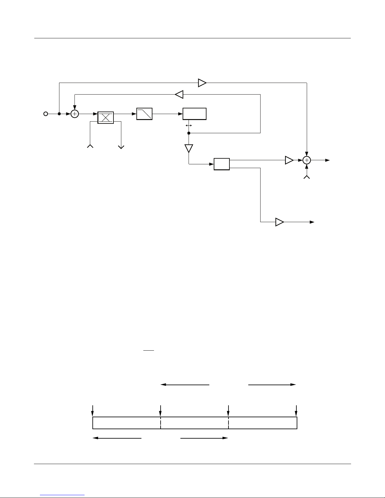
Feedback
FXAlgs #150Ð153: Choruses
Dry
L Input
Delay
High Freq
Damping
Tap Level Wet
From Right
Channel
To Right
Channel
Pan
From Right
Pans
Wet
Block diagram of left channel of Dual Chorus 1. Right channel is similar.
The left and right channels pass through their own chorus blocks. There may be cross-coupling between the
channels. For Chorus 2 and Dual Chorus 2, each channel has three moving taps which are summed, while Chorus
1 and Dual Chorus 1 have one moving tap for both channels. In the dual mono choruses you can pan the taps to left
or right. The summed taps (or the single tap of Chorus 1) is used for the wet output signal. The summed tap outputs,
weighted by their level controls, are used for feedback to the delay line input. The input and feedback signals go
through a one-pole lowpass filter (HF Damping) before going entering the delay line.
L Output
To Right
Output Sum
The Wet/Dry control is an equal power cross-fade. The Output Gain parameters affect both wet and dry signals.
For each of the LFO tapped delay lines, you may set the tap levels, the left/right pan position, delays of the
modulating delay lines, the rates of the LFO cycles, and the maximum depths of the pitch detuning. The LFOs
detune the pitch of signal copies above and
semitone.
In the stereo Chorus 1 and Chorus 2, the relative phases of the LFOs modulating the left and right channels may be
adjusted.
Delay Input
Algorithm Reference-51
below the original pitch. The depth units are in cents, or 1/100ths of a
Range of LFO
Shortest
Delay
Center
of LFO
Longest
Delay
LFO Xcurs LFO Xcurs
Tap Dly
Delay for a Single LFO
Page 52

FXAlgs #150Ð153: Choruses
The settings of the LFO rates and the LFO depths determine how far the LFOs will sweep across their delay lines
from the shortest delays to the longest delays (the LFO excursions). The Tap Delays specify the average amount of
delay of the LFO-modulated delay linesÑin other words, the timing of the center of the LFO excursion. The center
of LFO excursion can not move smoothly, and changing that parameter creates discontinuities in the tapped signal,
which is heard as zipper noise. It is therefore a good idea to adjust the Tap Dly parameter to a reasonable setting
(one which gives enough delay for the maximum LFO excursion), then leave it. If you increase the LFO modulation
depth or reduce the LFO rate to a point where the LFO excursion exceeds the specified Tap Dly, the center of LFO
excursion will be moved up, and again cause signal discontinuities. However, if enough Tap Dly is specified, Depth
and Rate will be modulated smoothly.
As the LFOs sweep across the delay lines, the signal will change pitch. The pitch will change with a triangular
envelope (rise-fall-rise-fall) or with a trapzoidal envelope (rise-hold-fall-hold). You can choose the pitch envelope
with the Pitch Env parameter. Unfortunately rate and depth cannot be smoothly modulated when set to the
ÒtrapzoidÓ setting.
Pit ch
Time Time
(i)
Pitch EnvelopeÑ(i) ÒTriangle"; (ii) ÒtrapzoidÓ
(ii)
Parameters (Chorus1):
PAGE 1
Wet/Dry -100 to 100%wet Out Gain Off, -79.0 to 24.0 dB
Fdbk Level -100 to 100%
Xcouple 0 to 100%
HF Damping 16 Hz to 25088 Hz Pitch Env Triangle or trapzoid
PAGE 2
Tap Lvl -100 to 100% LFO Rate 0.01 to 10.00 Hz
Tap Dly 0.0 to 1000.0 ms LFO Depth 0.0 to 50.0 ct
L/R Phase 0.0 to 360.0 deg
Parameters (Chorus 2):
PAGE 1
Wet/Dry -100 to 100%wet Out Gain Off, -79.0 to 24.0 dB
Fdbk Level -100 to 100%
Xcouple 0 to 100%
HF Damping 16 Hz to 25088 Hz Pitch Env Triangle or trapzoid
Algorithm Reference-52
Page 53

FXAlgs #150Ð153: Choruses
PAGE 2
Tap1 Lvl -100 to 100% Tap1 Dly 4.0 to 1000.0 ms
Tap2 Lvl -100 to 100% Tap2 Dly 4.0 to 1000.0 ms
Tap3 Lvl -100 to 100% Tap3 Dly 4.0 to 1000.0 ms
PAGE 3
LFO1 Rate 0.01 to 10.00 Hz LFO1 LRPhs 0.0 to 360.0 deg
LFO2 Rate 0.01 to 10.00 Hz LFO2 LRPhs 0.0 to 360.0 deg
LFO3 Rate 0.01 to 10.00 Hz LFO3 LRPhs 0.0 to 360.0 deg
LFO1 Dpth 0.0 to 50.0 ct
LFO2 Dpth 0.0 to 50.0 ct
LFO3 Dpth 0.0 to 50.0 ct
Parameters (Dual Chorus1):
PAGE 1
L Wet/Dry -100 to 100%wet R Wet/Dry -100 to 100%wet
L Out Gain Off, -79.0 to 24.0 dB R Out Gain Off, -79.0 to 24.0 dB
L Fdbk Lvl -100 to 100% R Fdbk Lvl -100 to 100%
Xcouple 0 to 100%
PAGE 2
L Tap Lvl -100 to 100% R Tap Lvl -100 to 100%
L Tap Pan -100 to 100% R Tap Pan -100 to 100%
L LFO Rate 0.01 to 10.00 Hz R LFO Rate 0.01 to 10.00 Hz
L LFODepth 0.0 to 50.0 ct R LFO Depth 0.0 to 50.0 ct
L Tap Dly 0.0 to 1000.0 ms R Tap Dly 0.0 to 1000.0 ms
L HF Damp 16 Hz to 25088 Hz R HF Damp 16 Hz to 25088 Hz
PAGE 3
L PitchEnv Triangle or trapzoid R PitchEnv Triangle or trapzoid
Algorithm Reference-53
Page 54

FXAlgs #150Ð153: Choruses
Parameters (Dual Chorus 2):
PAGE 1
L Wet/Dry -100 to 100%wet R Wet/Dry -100 to 100%wet
L Out Gain Off, -79.0 to 24.0 dB R Out Gain Off, -79.0 to 24.0 dB
L Fdbk Lvl -100 to 100% R Fdbk Lvl -100 to 100%
Xcouple 0 to 100%
PAGE 2
L Tap1 Lvl -100 to 100% R Tap1 Lvl -100 to 100%
L Tap2 Lvl -100 to 100% R Tap2 Lvl -100 to 100%
L Tap3 Lvl -100 to 100% R Tap3 Lvl -100 to 100%
L Tap1 Pan -100 to 100% R Tap1 Pan -100 to 100%
L Tap2 Pan -100 to 100% R Tap2 Pan -100 to 100%
L Tap3 Pan -100 to 100% R Tap3 Pan -100 to 100%
PAGE 3
L LFO1Rate 0.01 to 10.00 Hz R LFO1Rate 0.01 to 10.00 Hz
L LFO2Rate 0.01 to 10.00 Hz R LFO2Rate 0.01 to 10.00 Hz
L LFO3Rate 0.01 to 10.00 Hz R LFO3Rate 0.01 to 10.00 Hz
L LFO1Dpth 0.0 to 50.0 ct R LFO1Dpth 0.0 to 50.0 ct
L LFO2Dpth 0.0 to 50.0 ct R LFO2Dpth 0.0 to 50.0 ct
L LFO3Dpth 0.0 to 50.0 ct R LFO3Dpth 0.0 to 50.0 ct
PAGE 4
L Tap1 Dly 0.0 to 1000.0 ms R Tap1 Dly 0.0 to 1000.0 ms
L Tap2 Dly 0.0 to 1000.0 ms R Tap2 Dly 0.0 to 1000.0 ms
L Tap3 Dly 0.0 to 1000.0 ms R Tap3 Dly 0.0 to 1000.0 ms
L HF Damp 16 Hz to 25088 Hz R HF Damp 16 Hz to 25088 Hz
L PitchEnv Triangle or trapzoid R PitchEnv Triangle or trapzoid
W
et/Dry The relative amount of input (dry) signal and chorus (wet) signal that appears in the
Þnal effect output mix. When set to 0%, the output is taken only from the input. When
set to 100%, the output is all wet. Negative values polarity-invert the wet signal.
Out Gain The overall gain or amplitude at the output of the effect.
Fdbk Level The level of the feedback signal into the delay line. The feedback signal is taken from the
LFO1 delay tap. Negative values polarity-invert the feedback signal.
Xcouple Controls how much of the left channel input and feedback signals are sent to the right
channel delay line and vice versa. At 50%, equal amounts from both channels are sent to
both delay lines. At 100%, the left feeds the right delay and vice versa.
HF Damping The amount of high-frequency content of the signal that is sent into the delay lines. This
control determines the cutoff frequency of the one-pole (-6dB/octave) lowpass Þlter.
Pitch Env The pitch of the chorus modulation can be made to follow a triangular ÒTriangleÓ
envelope (rise-fall-rise-fall) or a trapzoidal ÒtrapzoidÓ envelope (rise-hold-fall-hold).
Algorithm Reference-54
Page 55

FXAlgs #150Ð153: Choruses
Tap Lvl Levels of the LFO-modulated delay taps. Negative values polarity-invert the signal.
Setting any tap level to 0% effectively turns off the delay tap. Since these controls allow
the full input level to pass through all the delay taps, a 100% setting on all the summed
taps will signiÞcantly boost the wet signal relative to dry. A 50% setting may be more
reasonable.
Tap Pan The left or right output panning of the delay taps. The range is -100% for fully left to
100% for fully right. Setting the pan to 0% sends equal amounts to both left and right
channels for center or mono panning. [Dual Chorus 1 & 2 only]
LFO Rate Used to set the speeds of modulation of the delay lines. Low rates increase LFO
excursion (see LFO Dpth below). If Pitch Env is set to ÒtrapzoidÓ, you will be unable to
put the rate on an FXMod or otherwise change the rate without introducing
discontinuities (glitches or zippering) to your output signal. The triangular ÒTriangleÓ
Pitch Env setting does allow smooth rate modulation, provided youÕve speciÞed enough
delay.
LFO Depth
The maximum depth of detuning of the LFO-modulated delay lines. The range is 0 to 50
cents, with a cent equal to 1/100th of a semitone. If you do not have enough delay
speciÞed with Tap Dly to get the depth youÕve dialed up, then Tap Dly will be forced to
increase, which can cause discontinuities if signal is present. The LFOs move a tap back
and forth across the delay lines to shift the pitch of the tapped signal. The maximum
distance the taps get moved from the center position of the LFO is called the LFO
excursion. Excursion is calculated from both the LFO depth and rate settings. Large
depths and low rates produce large excursions. If Pitch Env is set to ÒtrapzoidÓ, you will
be unable to put the depth on an FXMod or otherwise change the depth without
introducing discontinuities (glitches or zippering) to your output signal. The triangular
ÒTriangleÓ Pitch Env setting does allow smooth depth modulation, provided youÕve
speciÞed enough delay.
Tap Dly The average delay length, or the delay to the center of the LFO sweep. If the delay is
shorter than the LFO excursion, then the Tap Dly will be forced to a longer length, equal
to the amount of required excursion (the parameter display will not change though).
Changing this parameter while signal is present will cause signal discontinuities. ItÕs
best to set and forget this one. Set it long enough so that there are no discontinuities with
the largest Depth and lowest Rates that you will be using.
L/R Phase or LFOn LRPhs In Chorus 1 and Chorus 2, the relative phases of the LFOs for the left and right
channels may be adjusted.
Algorithm Reference-55
Page 56

FXAlg #154: Flanger 1 ¥ FXAlg #155: Flanger 2
FXAlg #154: Flanger 1 ¥
FXAlg #155: Flanger 2
Multi-tap flangers
Allocation Units: 1 for Flanger 1; 2 for Flanger 2
Flanger 1 is a 1-PAU multi-sweep Thru-zero flanger effect with two LFOs per channel.
Dry
L Input
Delay
From Right
Channel
High Freq
Damping
To Right
Channel
Feedback
LFO
Tap
Levels
Wet
Simplified block diagram of the left channel of Flanger 1; the Right channel is similar.
Flanger 2 is a 2-PAU multi-sweep Thru-zero flanger effect with two LFOs per channel.
Dry
Noise
L Input
Delay
From Right
Channel
High Freq
Damping
To Right
Channel
LFO
Tap
Levels
Static
Tap
Level
L Output
Out Gain
Static
Tap
Level
Simplified block diagram of the left channel of Flanger 2; the Right channel is similar.
Algorithm Reference-56
LFO Feedback
Static Tap Feedback
Wet
L Output
Out Gain
Page 57

FXAlg #154: Flanger 1 ¥ FXAlg #155: Flanger 2
Flanging was originally created by summing the outputs of two un-locked tape machines while varying their sync
by pressing a hand on the outside edge of one reelÑthus the name Òreel-flangingÓ. The key to achieving the
flanging effect is the summing of a signal with a time-displaced replica of itself.
The result is a series of notches in the frequency spectrum. These notches are equally spaced in (linear) frequency
at multiples whose wavelengths are equal to the time delay. The result is generally referred to as a comb filter (the
name arising from the resemblance of the spectrum to a comb). If the levels of the signals being added or subtracted
are the same, the notches will be of infinite depth (in dB) and the peaks will be up 6 dB. Flanging is achieved by
time-varying the delay length, thus changing the frequencies of the notches. The shorter the delay time, the greater
the notch separation. This delay time variation imparts a sense of motion to the sound. Typically the delay times are
on the order of 0-5 ms. Longer times begin to get into the realm of chorusing, where the ear begins to perceive the
audio output as nearly two distinct signals, but with a variable time displacement.
10
Amp
(dB)
0
10
20
Frequency
Comb Filters - Solid Line for Addition, Dashed Line for Subtraction
The heart of the flanger implemented here is a multi-tap delay line. You can set the level of each tap as a percentage
of the input level, and the level may be negative (phase-inverted). One tap is a simple static delay over which you
can control the length of delay (from the input tap). Four of the taps can have their lengths modulated up and down
by a low frequency oscillator (LFO). You are given control of the rate of the LFOs, how far each LFO can sweep
through the delay line, and the relative phases of the LFOs (i.e., whether the LFO is taking the taps from the input
tap or bringing them toward it).
The flanger uses tempo units (based on the sequencer tempo or MIDI clock if you like), together with the number
of tempo beats per LFO cycle. Thus if the tempo is 120 bpm (beats per minute) and the LFO Period is set to 1 beat,
the LFOs will pass through 120 complete cycles in a minute or 2 cycles per second (2 Hz). Increasing the LFO Period
increases the period of the LFOs (slows them down). An LFO Period setting of 16 beats will take 4 measures (in 4/4
time) for a complete LFO oscillation.
Algorithm Reference-57
Page 58

FXAlg #154: Flanger 1 ¥ FXAlg #155: Flanger 2
You can set how far each LFO can sweep through the delay line with the excursion controls (Xcurs). The excursion
is the maximum distance an LFO will move from the center of its sweep. The total range of an LFO is twice the
excursion. You set the delay to the center of LFO excursion with the Dly parameters. The excursion and delay
controls both have coarse and fine adjustments. By setting the excursion to zero length, the LFO delay tap becomes
a simple static tap. Note that modifying the delay to the center of LFO excursion will result in a sudden change of
delay length and consequently, a discontinuity in the signal being read from the delay line. This can produce a
characteristic zippering effect. The Dly parameters should be as long as the Xcurs parameters or longer, or else
changing (or modulating) the excursion will force the center of LFO excursion to move, with the resulting signal
discontinuities. The static delay tap does not suffer the zippering problem, and changes to its length will occur
smoothly. You can assign the static delay tap to an FX Mod, and use the source controller to do manual flanging.
Range of LFO
Delay Input
Shortest
Delay
Tap Dly
Center
of LFO
LFO Xcurs LFO Xcurs
Longest
Delay
Delay for a Single LFO
Consider a simple example where you have an LFO tap signal being subtracted from the static delay tap signal. If
the delays are set such that at certain times both taps are the same length, then both taps have the same signal and
the subtraction produces a null or zero output. The effect is most pronounced when the static tap is set at one of the
ends of the LFO excursion where the LFO tap motion is the slowest. This is the classic Thru-Zero flanger effect.
Adding other LFO taps to the mix increases the complexity of the final sound, and obtaining a true Thru-Zero effect
may take some careful setting of delays and LFO phases.
The flanger has a Wet/Dry control as well, which can further add complexity to the output as the dry signal is
added to various delayed wet components for more comb filtering.
When using more than one LFO, you can set up the phase relationships between each of the LFOs. The LFOs of the
left channel and those of the right channel will be set up in the same phase relationship except that you may offset
the phases of the right channel as a group relative to the left channel (L/R Phase). L/R Phase is the only control
which treats left and right channels differently and has a significant effect on the stereo image. If you have tempo
set to the system tempo, the phases will maintain their synchronization with the tempo clock. At the beat of the
tempo clock, a phase set to 0° will be at the center of the LFO excursion and moving away from the delay input.
Regenerative feedback has been incorporated in order to produce a more intense resonant effect. The signal is fed
back is from the first LFO delay tap (LFO1), and has its own level control (Fdbk Level). In-phase spectral
components arriving at the summer add together, introducing a series of resonant peaks in the frequency spectrum
between the notches. The amplitude of these peaks depends on the degree of feedback, and they can be made very
resonant.
Cross-coupling (Xcouple) allows the signals of the right and left channels to be mixed or swapped. The crosscoupling is placed after the summation of the feedback to the input signal. When feedback and cross-coupling are
turned up, you will get a ping-pong effect between right and left channels.
A lowpass filter (HF Damping) right before the input to the delay line is effective in emulating the classic sounds of
older analog flangers with their limited bandwidths (typically 5-6kHz).
As stated earlier, it is the movement of the notches created in the frequency spectrum that give the flanger its unique
Algorithm Reference-58
Page 59

FXAlg #154: Flanger 1 ¥ FXAlg #155: Flanger 2
sound. It should be obvious that sounds with a richer harmonic structure will be effected in a much more dramatic
way than harmonically starved sounds. Having more notches, i.e. a greater Ônotch-densityÕ, should produce an even
more intense effect. This increase in notch density may be achieved by having a number of modulating delay lines,
all set at the same rate, but different depths. Setting the depths proportionately results in a more pleasing effect.
An often characteristic effect of flanging is the sound of system noise being flanged. Various pieces of analog gear
add noise to the signal, and when this noise passes through a flanger, you can hear the noise ÒwhooshingÓ. In the
K2500, the noise level is very low, and in fact if no sound is being played, there is no noise at all at this point in the
signal chain. To recreate the effect of system noise flanging, white noise may be added to the input of the flanger
signal (Flanger 2 only). Since white noise has a lot of high frequency content and may sound too bright, it may be
tamed with a first-order lowpass filter.
Parameters (Flanger 1):
PAGE 1
Wet/Dry -100 to 100% wet Out Gain Off, -79.0 to 24.0 dB
Fdbk Level -100 to 100% LFO Tempo System, 1 to 255 BPM
Xcouple 0 to 100% LFO Period 1/24 to 32 bts
HF Damping 16 to 25088 Hz
PAGE 2
StatDlyLvl -100 to 100% L/R Phase 0.0 to 360.0 deg
LFO1 Level -100 to 100% LFO1 Phase 0.0 to 360.0 deg
LFO2 Level -100 to 100% LFO2 Phase 0.0 to 360.0 deg
PAGE 3
StatDlyCrs 0.0 to 228.0 ms
StatDlyFin -127 to 127 samp
Xcurs1 Crs 0.0 to 228.0 ms Dly1 Crs 0.0 to 228.0 ms
Xcurs1 Fin -127 to 127 samp Dly1 Fin -127 to 127 samp
Xcurs2 Crs 0.0 to 228.0 ms Dly2 Crs 0.0 to 228.0 ms
Xcurs2 Fin -127 to 127 samp Dly2 Fin -127 to 127 samp
Parameters (Flanger 2):
PAGE 1
Wet/Dry -100 to 100%wet Out Gain Off, -79.0 to 24.0 dB
LFO Fdbk -100 to 100% Stat Fdbk -100 to 100%
Xcouple 0 to 100% LFO Tempo System, 1 to 255 BPM
HF Damping 16 Hz to 25088 Hz LFO Period 1/24 to 32 bts
Algorithm Reference-59
Page 60

FXAlg #154: Flanger 1 ¥ FXAlg #155: Flanger 2
PAGE 2
Noise Gain Off, -79.0 to -30.0 dB Noise LP 16 to 25088 Hz
StatDlyLvl -100 to 100% L/R Phase 0.0 to 360.0 deg
LFO1 Level -100 to 100% LFO1 Phase 0.0 to 360.0 deg
LFO2 Level -100 to 100% LFO2 Phase 0.0 to 360.0 deg
LFO3 Level -100 to 100% LFO3 Phase 0.0 to 360.0 deg
LFO4 Level -100 to 100% LFO4 Phase 0.0 to 360.0 deg
PAGE 3
StatDlyCrs 0.0 to 228.0 ms
StatDlyFin -127 to 127 samp
Xcurs1 Crs 0.0 to 228.0 ms Xcurs3 Crs 0.0 to 228.0 ms
Xcurs1 Fin -127 to 127 samp Xcurs3 Fin -127 to 127 samp
Xcurs2 Crs 0.0 to 228.0 ms Xcurs4 Crs 0.0 to 228.0 ms
Xcurs2 Fin -127 to 127 samp Xcurs4 Fin -127 to 127 samp
PAGE 4
Dly1 Crs 0.0 to 228.0 ms Dly3 Crs 0.0 to 228.0 ms
Dly1 Fin -127 to 127 samp Dly3 Fin -127 to 127 samp
Dly2 Crs 0.0 to 228.0 ms Dly4 Crs 0.0 to 228.0 ms
Dly2 Fin -127 to 127 samp Dly4 Fin -127 to 127 samp
et/Dry The relative amount of input signal and ßanger signal that is to appear in the Þnal effect
W
output mix. When set to 0%, the output is taken only from the input (dry). When set to
100%, the output is all wet. Negative values polarity-invert the wet signal.
Out Gain The overall gain or amplitude at the output of the effect.
Fdbk Level The level of the feedback signal into the delay line. The feedback signal is taken from the
LFO1 delay tap. Negative values polarity-invert the feedback signal.
Xcouple How much of the left channel input and feedback signals are sent to the right channel
delay line and vice versa. At 50%, equal amounts from both channels are sent to both
delay lines. At 100%, the left feeds the right delay and vice versa. Xcouple has no effect if
Fdbk Level is set to 0%.
HF Damping The amount of high frequency content of the signal sent into the delay lines. This control
determines the cutoff frequency of the one-pole (-6dB/octave) lowpass Þlters.
LFO Tempo Basis for the rates of the LFOs, as referenced to a musical tempo in bpm (beats per
minute). When this parameter is set to ÒSystemÓ, the tempo is locked to the internal
sequencer tempo or to incoming MIDI clocks. When it is set to ÒSystemÓ, sources (FUNs,
LFOs, ASRs etc.) will have no effect on the Tempo parameter.
LFO Period Sets the LFO rate based on the Tempo determined above: the number of beats
corresponding to one period of the LFO cycle. For example, if the LFO Period is set to
Ò4Ó, the LFOs will take four beats to pass through one oscillation, so the LFO rate will be
1/4th of the Tempo setting. If it is set to Ò6/24Ó (=1/4), the LFO will oscillate four times
as fast as the Tempo. At Ò0Ó, the LFOs stop oscillating and their phase is undetermined
(wherever they stopped).
Algorithm Reference-60
Page 61

FXAlg #154: Flanger 1 ¥ FXAlg #155: Flanger 2
Noise Gain The amount of noise (dB relative to full scale) to add to the input signal. In many
ßangers, you can hear the noise ßoor of the signal being ßanged, but in the K2500, if
there is no input signal, there is no noise ßoor unless it is explicitly added. [Flanger 2
only]
Noise LP The cut-off frequency of a one-pole lowpass Þlter acting on the injected noise. The
lowpass removes high frequencies from an otherwise pure white noise signal. [Flanger 2
only]
StatDlyCrs The coarse adjustment to the static delay tap length. The name suggests the tap is
stationary, but it can be connected through an FX Mod to a control source to smoothly
vary the delay length. The range for all delays and excursions is 0 to 230 ms, but for
ßanging the range 0 to 5 ms is most effective.
StatDlyFin A Þne adjustment to the static delay tap length. The resolution is one sample.
StatDlyLvl The level of the static delay tap. Negative values polarity-invert the signal. Setting the
tap level to 0% turns off the delay tap.
Xcurs n Crs These set how far the LFO-modulated delay taps can move from the center of their
ranges. The total range of the LFO sweep is twice the excursion. If the excursion is set to
0, the LFO does not move and the tap behaves like a simple delay line set to the
minimum delay. The excursion cannot be made longer than the delay to the center of
excursion (see Dly Crs and Dly Fin below) because delays cannot be made shorter than
0. If you attempt longer excursions, the length of the Dly Crs/Fin will be forced to
increase (though you will not see the increased length displayed in the Dly Crs/Fin
parameters), and you will hear discontinuities in the signal, usually in the form of zipper
noise. The range for all delays and excursions is 0 to 230 ms, but for ßanging the range 0
to 5 ms is most effective. This parameter is a coarse adjustment for the excursion.
Xcurs n Fin A Þne adjustment for the LFO excursions. The resolution is one sample.
Dly n Crs The delay to the center of LFO tap range. The maximum delay will be this delay plus the
LFO excursion delay. The minimum delay will be this delay minus the LFO excursion
delay. Since delays cannot be less than 0 ms in length, the this delay length will be
increased if LFO excursion is larger than this delay length. The range for all delays and
excursions is 0 to 230 ms, but for ßanging the range 0 to 5 ms is most effective. This
parameter is a coarse adjustment for the delay.
Dly n Fin A Þne adjustment to the minimum delay tap lengths. The resolution is one sample.
LFOn Level The levels of the LFO modulated delay taps. Negative values polarity-invert the signal.
Setting any tap level to 0% turns off the delay tap.
LFOn Phase The phase angles of the LFOs relative to each other and to the system tempo clock, if
turned on (see Tempo). For example, if one LFO is set to 0° and another is set to 180°,
then when one LFO delay tap is at its shortest, the other will be at its longest. If the
system tempo clock is on, the LFOs are synchronized to the clock with absolute phase. A
phase of 0° will put an LFO tap at the center of its range and its lengthening.
L/R Phase Adds the speciÞed phase angle to the right channel LFOs. In all other respects the right
and left channels are symmetric. By moving this control away from 0°, the stereo sound
Þeld is broken up and a stereo image becomes difÞcult to spatially locate. The effect is
usually described as ÒphaseyÓ. It tends to impart a greater sense of motion.
Algorithm Reference-61
Page 62

FX Algs #156-160: Phasers
FX Algs #156-160: Phasers
FXAlg #156: LFO Phaser
FXAlg #157: LFO Phaser Twin
FXAlg #158: Manual Phaser
FXAlg #159: Vibrato Phaser
FXAlg #160: SingleLFO Phaser
A variety of single notch/bandpass Phasers
Allocation Units: 1 (each)
A simple phaser is an algorithm which produces a vague swishing or phasey effect. When the phaser signal is
combined with the dry input signal or the phaser is fed back on itself, peaks and/or notches can be produced in the
filter response making the effect much more pronounced. Most of the phaser algorithms presented here have built
in low frequency oscillators (LFOs) to generate the motion of the phasers. In the case of Manual Phaser, the phaser
motion is left to the user.
Dry
Input Output
A phaser uses a special filter called an all-pass filter to modify the phase response of a signalÕs spectrum without
changing the amplitude of the spectrum. As the name suggests, an all-pass filter by itself does not change the
amplitude of the frequency response of a signal passing through itÑit does not cut or boost any frequencies. It does
cause some frequencies to be delayed a little in time, and this small time shift is also known as a phase change. The
frequency where the phase change has its greatest effect is a parameter that you can control. By modulating the
frequency of the phaser, you get the swishy phaser sound. With a modulation rate of around 6 Hz, an effect similar
to vibrato may be obtained, but only in a limited range of filter frequencies.
By adding the phaser output to the dry input using, for example, a Wet/Dry parameter, you can produce peaks and
notches in the frequency response. At frequencies where the phaser is Òin phaseÓ with the dry signal, the signal level
doubles (or there is a 6 dB level increase approximately). At frequencies where the phaser and dry signals are Òout
of phaseÓ, the two signals cancel each other out and there is a notch in the frequency response. You can get a
complete notch when Wet/Dry is set to 50%. If subtraction is used instead of addition by setting Wet/Dry to -50%,
then the notches become peaks and the peaks become notches.
AP
Wet
Feedback
One channel of a typical phaser
Algorithm Reference-62
Page 63

FX Algs #156-160: Phasers
Gain
0 dB
-20
-40
10 Hz 100 1000 10k
Freq
(i) (ii)
Gain
0 dB
-20
-40
10 Hz 100 1000 10k
Freq
Response of typical phaser: (i) Wet/Dry = 50% and (ii) Wet/Dry = -50%.
Some of the phaser algorithms have feedback. When feedback is used, it can greatly exaggerate the peaks and
notches, producing a much more resonant sound.
LFO Phaser is a simple phaser algorithm with Wet/Dry and Fdbk Level parameters. Two LFOs used to control the
filter frequency and the depth of the resulting notch. You can control the depths, rates, and phases of both the LFOs.
The algorithm is stereo so the relative phases of the LFOs for the left and right channels can be set. When setting the
LFO that controls the filter frequency, you specify the center frequency around which the LFO will modulate and
the depth of the LFO. The depth specifies how many cents (hundredths of a semitone) to move the filter frequency
up and down.
The NotchDepth parameter provides an alternative way of combining wet and dry phaser signals to produce a
notch. In this case the parameter specifies the depth of the notch in decibels (dB). The depth of the notch can be
modulated with the notch LFO. The notch LFO is completely independent of the frequency, and their rates may be
different. The relative phases of the notch and frequency LFOs (N/F Phase) only has meaning when the LFOs are
running at the same rate. As with all KDFX LFO phases, it is not recommended to directly modulate the phase
settings with an FXMod.
SingleLFO Phaser is identical to LFO Phaser except that the notch and frequency LFOs always run at the same rate.
Manual Phaser leaves the phaser motion up to you, so it has no built in LFOs. Manual Phaser has a Notch/BP
parameter which produces a complete notch at the center frequency when Wet/Dry is set to -100% and a resonant
bandpass when set to 100%. At 0% the signal is dry. To get phaser motion, you have to change the filter center
frequencies (left and right channels) yourself. The best way to do this is with an FXMod. There are also feedback
parameters for the left and right channels.
LFO Phaser Twin produces a pair of notches separated by a spectral peak. The center frequency parameter sets the
frequency of the center peak. Like LFO Phaser, the filter frequency can be modulated with a built in LFO. The
Notch/Dry parameter produces a pair of notches when set to 100%. The output signal is dry when set to 0% and at
200%, the signal is a pure (wet) allpass response. LFO Phaser Twin does not have Out Gain or feedback parameters.
Algorithm Reference-63
Page 64

FX Algs #156-160: Phasers
Gain
0 dB
-20
-40
10 Hz 100 1000 10k
Freq
Response of LFO Phaser Twin with Wet/Dry set to 100%.
In the Vibrato Phaser algorithm, the bandwidth of the phaser filter can be adjusted exactly like a parametric EQ
filter. The In Width controls how the stereo input signal is routed through the effect. At 100% In Width, left input is
processed to the left output, and right to right. Lower In Width values narrow the input stereo field until at 0%, the
processing is mono. Negative values reverse left and right channels. The dry signal is not affected by In Width. As
described earlier, setting Wet/Dry to 50% will produce a full notch. At -50% Wet/Dry, you get a bandpass.
Parameters (LFO Phaser):
PAGE 1
Wet/Dry 0 to 100%wet Out Gain Off, -79.0 to 24.0 dB
Fdbk Level -100 to 100%
PAGE 2
CenterFreq 16 to 25088 Hz NotchDepth -79.0 to 6.0 dB
FLFO Depth 0 to 5400 ct NLFO Depth 0 to 100%
FLFO Rate 0.00 to 10.00 Hz NLFO Rate 0.00 to 10.00 Hz
FLFO LRPhs 0.0 to 360.0 deg NLFO LRPhs 0.0 to 360.0 deg
N/F Phase 0.0 to 360.0 deg
Algorithm Reference-64
Page 65

FX Algs #156-160: Phasers
Parameters (SingleLFO Phaser):
PAGE 1
Wet/Dry 0 to 100%wet Out Gain Off, -79.0 to 24.0 dB
Fdbk Level -100 to 100%
PAGE 2
LFO Rate 0.00 to 10.00 Hz N/F Phase
CenterFreq 16 to 25088 Hz NotchDepth -79.0 to 6.0 dB
FLFO Depth 0 to 5400 ct NLFO Depth 0 to 100%
FLFO LRPhs 0.0 to 360.0 deg NLFO LRPhs 0.0 to 360.0 deg
Wet/Dry The amount of phaser (wet) signal relative to unaffected (dry) signal as a percent.
Out Gain The output gain in decibels (dB) to be applied to the combined wet and dry signals.
Fdbk Level The phaser output can be added back to its input to increase the phaser resonance.
Negative values polarity-invert the feedback signal.
LFO Rate The rate of both the center frequency LFO and the notch depth LFO for the SingleLFO
Phaser algorithm.
CenterFreq The nominal center frequency of the phaser Þlter. The frequency LFO modulates the
phaser Þlter centered at this frequency.
FLFO Depth The depth in cents that the frequency LFO sweeps the phaser Þlter above and below the
center frequency.
FLFO Rate The rate of the center frequency LFO for the LFO Phaser algorithm.
FLFO LRPhs Sets the phase difference between the left and right channels of the center frequency
LFO. A setting of 180 degrees results in one channel being at the minimum frequency
while the other channel is at the maximum.
NotchDepth The nominal depth of the notch. The notch depth LFO modulates the depth of the notch.
For maximum LFO depth, set NotchDepth to 0 dB and NLFO Depth to 100%.
NLFO Depth The excursion of the notch depth LFO in units of percentage of the total range. The
depth of the LFO is limited to the range of the NotchDepth parameter such that a full
100% modulation is only possible when the NotchDepth is at the center of its range (0
dB).
NLFO Rate The rate of the notch depth LFO for the LFO Phaser algorithm.
NLFO LRPhs The phase difference between the left and right channels of the notch depth LFO. A
setting of 180 degrees results in one channel being at highest amplitude while the other
channel is at lowest amplitude.
N/F Phase The phase difference between the notch depth and center frequency LFOs. For LFO
Phaser, this parameter is largely meaningless unless the FMod Rate and NMod Rate are
set identically.
Algorithm Reference-65
Page 66

FX Algs #156-160: Phasers
Parameters (Manual Phaser):
PAGE 1
Notch/BP -100 to 100% Out Gain Off, -79.0 to 24.0 dB
L Feedback -100 to 100% R Feedback -100 to 100%
L Ctr Freq 16 to 25088 Hz R Ctr Freq 16 to 25088 Hz
Notch/BP The amount of notch depth or bandpass. At -100% there is a complete notch at the center
frequency. At 100% the Þlter response is a peak at the center frequency. 0% is the dry
unaffected signal.
Out Gain The output gain in decibels (dB) to be applied to the Þnal output.
Feedback The phaser output can be added back to its input to increase the phaser resonance (left
and right). Negative values polarity-invert the feedback signal.
Ctr Freq The nominal center frequency of the phaser Þlter (left and right). For a true phaser effect
you may want to modulate these parameters by setting up FX Mods.
Parameters (LFO Phaser Twin):
PAGE 1
Notch/Dry 0 to 200%
CenterFreq 16 to 25088 Hz LFO Rate 0.00 to 10.00 Hz
LFO Depth 0 to 5400 ct L/R Phase 0.0 to 360.0 deg
Notch/Dry The amount of phaser (wet) signal relative to unaffected (dry) signal as a percent. At
100% the phaser produces a pair of full notches above and below the center frequency.
At 200% the output is a pure all-pass response (no amplitude changes, but phase
changes centered about the center frequency).
CenterFreq The nominal center frequency of the phaser Þlter. When conÞgured for a maximum
notch (Notch/Dry is 100%), the CenterFreq speciÞes the frequency of the peak between
two notches. The LFO modulates the phaser Þlter centered at this frequency.
LFO Rate The rate of the phaser frequency modulating LFO in Hertz.
LFO Depth The depth in cents that the frequency LFO sweeps the phaser Þlter above and below the
center frequency.
L/R Phase The phase difference between the left and right channels of the LFO. A setting of 180
degrees results in one channel being at the minimum frequency while the other channel
is at the maximum.
Algorithm Reference-66
Page 67

FX Algs #156-160: Phasers
Parameters (Vibrato Phaser):
PAGE 1
Wet/Dry -100 to 100%wet Out Gain Off, -79.0 to 24.0 dB
PAGE 2
CenterFreq 16 to 25088 Hz Bandwidth 0.010 to 5.000 oct
LFO Depth 0 to 100% L/R Phase 0.0 to 360.0 deg
LFO Rate 0.00 to 10.00 Hz
In Width -100 to 100%
Wet/Dry The amount of phaser (wet) signal relative to unaffected (dry) signal as a percent. When
set to 50% you get a complete notch. When set to -50%, the response is a bandpass Þlter.
100% is a pure allpass Þlter (no amplitude changes, but a strong phase response).
Out Gain The output gain in decibels (dB) to be applied to the combined wet and dry signals.
CenterFreq The nominal center frequency of the phaser Þlter. The frequency LFO modulates the
phaser Þlter centered at this frequency.
Bandwidth If the phaser is set to behave as a sweeping notch or bandpass, the bandwidth of the
notch or bandpass is set with Bandwidth. This parameter works the same as for
parametric EQ Þlter bandwidths.
LFO Depth The depth that the frequency LFO sweeps the phaser Þlter above and below the center
frequency as a percent.
LFO Rate The rate of the LFO in Hertz. The LFO Rate may be scaled up by the Rate Scale
parameter.
L/R Phase Sets the phase difference between the left and right channels of the center frequency
LFO. A setting of 180 degrees results in one being at a at the minimum frequency while
the other channel is at the maximum.
In Width The width of the stereo Þeld that passes through the stereo phaser Þltering. This
parameter does not affect the dry signal. When set to 100%, the left and right channels
are processed to their respective outputs. Smaller values narrow the stereo image until at
0% the input channels are summed to mono and set to left and right outputs. Negative
values interchange the left and right channels.
Algorithm Reference-67
Page 68

Combination Algorithms [Ò+Ó]
Combination Algorithms [Ò+Ó]
FXAlg #700 Ñ Chorus+Delay
FXAlg #701 Ñ Chorus+4Tap
FXAlg #703 Ñ Chor+Dly+Reverb
FXAlg #706 Ñ Flange+Delay
FXAlg #707 Ñ Flange+4Tap
FXAlg #709 Ñ Flan+Dly+Reverb
FXAlg #722 Ñ Pitcher+Chor+Dly
FXAlg #723 Ñ Pitcher+Flan+Dly
A family of combination effect algorithms
Allocation Units: 1 or 2
Signal Routing (2 effects)
The algorithms listed above with two effects can be arranged in series or parallel. The output of the first effect in the
algorithm nameÑAÑis wired to the input of the second effectÑBÑand the input into effect B is a mix of effect A
and the algorithm input dry signal. The effect B input mix is controlled by a parameter A/Dry>B. For example, in
Chorus+Delay, the parameter name is ÒCh/Dry>DlyÓ. The value functions much like a wet/dry mix where 0%
means that only the algorithm input dry signal is fed into effect B, thus putting the effects in parallel; and 100%
means only the output of effect A is fed into effect B, thus putting the effects in series.
Ch/Dry->4T
L Input
Chorus
Both effect A and B outputs are mixed at the algorithm output to become the wet signal. These mix levels are
controlled with the two parameters that begin with ÒMixÓ. These allow only one or both effect outputs to be heard.
Negative mix amounts polarity-invert the signal, which can change the character of each effect when mixed
together or with the dry signal. The Wet/Dry parameter adjusts the balance between the sum of both effects
determined by the Mix parameters, and the input dry signal. Negative Wet/Dry values polarity-invert the summed
wet signal relative to dry.
Blend
An example of routing using Chorus+4Tap
4-Tap
Delay
Mix 4 Tap
Mix Chorus
Wet/Dry
Blend
Output
Out Gain
Two-Effect Routing:
Wet/Dry -100 to 100% Out Gain Off; -79.0 to 24.0 dB
Mix Effect -100 to 100%
Mix Effect -100 to 100%
A/Dry->B 0 to 100%
Algorithm Reference-68
Page 69

Combination Algorithms [Ò+Ó]
Mix Effect Adjusts the amount of each effect that is mixed together as the algorithm wet signal.
Negative values polarity-invert that particular signal.
A/Dry->B This parameter controls how much of the A effect is mixed with dry and fed into the B
effect. A and B are designated in the algorithm name. This control functions like a
wet/dry mix, where 0% is completely dry and 100% is effect A only.
Signal Routing (3 effects)
The algorithms listed above with three effects allow serial or parallel routing between any three effects. Effect A is
wired to the input of effect B and C, and effect B is wired into effect C. The input of effect B is a mix between effect
A and the algorithm dry input. The input into effect C is a three-way mix between effect A, effect B, and the dry
signal.
As in the two-effect routing, the input of effect B is controlled by a parameter A/Dry>B. For example, in
Chor+Dly+Rvb, the parameter name is ÒCh/Dry>DlyÓ.
The input into effect C is controlled by two parameters named A/B ->* and */Dry->C where A, B, and C
correspond to the names of effects A, B, and C. The first parameter mixes effect A and B into a temporary buffer
represented by the symbol Ò*Ó. The second parameter mixes this temporary buffer Ò*Ó with the dry signal to be fed
into effect C. These mixing controls function similarly to Wet/Dry parameters. A setting of 0% only mixes the effect
to the right of the Ò/Ó in the parameter name, while 100% only mixes the effect to the left of the Ò/Ó. Negative values
polarity-invert the numeratorÕs signal.
Effects A, B, and C outputs are mixed at the algorithm output to become the wet signal. Separate mixing levels are
provided for left and right channels, and are named ÒL MixÓ or ÒR MixÓ. Negative mix amounts polarity-invert the
signal which can change the character of each effect when mixed together or with the dry signal. The Wet/Dry
parameter adjusts the balance between the sum of all effects determined by the Mix parameters, and the input dry
signal. Negative Wet/Dry values polarity-invert the summed wet signal relative to dry.
Input
Chorus
Reverb
Ch/Dry->Dly
Blend
Mix Delay
Mix Chorus
Mix Reverb
Delay
Wet/Dry
Blend
Ch/Dly->*
Blend
Out Gain
*/Dry->Rvb
Blend
Output
An example of routing using Chorus+Delay+Reverb
Algorithm Reference-69
Page 70

Combination Algorithms [Ò+Ó]
Three-Effect Routing:
Wet/Dry -100 to 100% Out Gain Off; -79.0 to 24.0 dB
L Mix Effect A -100 to 100% R Mix Effect A -100 to 100%
L Mix Effect B -100 to 100% R Mix Effect B -100 to 100%
L Mix Effect C -100 to 100% R Mix Effect C -100 to 100%
A/Dry>B -100 to 100%
A/B ->* -100 to 100%
*/Dry->C -100 to 100%
L Mix Effect, R Mix Effect Adjusts the amount of each effect that is mixed together as the algorithm wet signal.
Separate left and right controls are provided. Negative values polarity-invert that
particular signal.
A/Dry>B This parameter controls how much of the A effect is mixed with dry and fed into the B
effect. A and B are designated in the algorithm name. This control functions like a
wet/dry mix, where 0% is completely dry and 100% is effect A only.
A/B ->* This parameter is Þrst of two parameters that control whet is fed into effect C. This
adjusts how much of the effect A is mixed with effect B, the result of which is
represented as the symbol Ò*Ó. 0% is completely B effect, and 100% is completely A
effect. negative values polarity-invert the A effect.
*/Dry->C This parameter is the second of two parameters that control whet is fed into effect C.
This adjusts how much of the Ò*Ó signal (sum of effects A and B determined by A/B ->*)
is mixed with the dry signal and fed into effect C. 0% is completely dry signal, and 100%
is completely Ò*Ó signal.
Individual Effect Components
Chorus:
The choruses are basic 1 tap dual choruses. Separate LFO controls are provided for each channel. Slight variations
between algorithms exist. Some algorithms offer separate left and right feedback controls, while some offer only one
for both channels. Also, cross-coupling and high frequency damping may be offered in some and not in others.
Parameters associated with chorus control begin with ÒChÓ in the parameter name. A general description of chorus
functionality can be found in the Chorus section of this book, FXAlgs #150-153.
Ch PtchEnv Triangle or trapzoid
Ch Rate L 0.01 to 10.00 Hz Ch Rate R 0.01 to 10.00 Hz
Ch Depth L 0.0 to 100 ct Ch Depth R 0.0 to 100 ct
Ch Delay L 0 to 1000 ms Ch Delay R 0 to 1000 ms
Ch Fdbk -100 to 100%
Ch Xcouple 0 to 100% Ch HF Damp 16 to 25088 Hz
Algorithm Reference-70
Page 71

Combination Algorithms [Ò+Ó]
Flange:
The flangers are basic 1-tap dual flangers. Separate LFO controls are provided for each channel. Slight variations
between algorithms exist. Some algorithms offer separate left and right feedback controls, while some offer only one
for both channels. Also, cross-coupling and high-frequency damping may be offered in some and not in others.
Parameters associated with flange control begin with ÒFlÓ in the parameter name. A general description of flanger
functionality can be found in the Flanger section or this book, FXAlgs #154-155.
In addition to the LFO delay taps, some flangers may offer a static delay tap for creating through-zero flange effects.
The maximum delay time for this tap is 230ms and is controlled by the Fl StatDly parameter. Its level is controlled
by the Fl StatLvl parameter.
PAGE 1
Fl Tempo System; 1 to 255 BPM Fl HF Damp 16 to 25088 Hz
Fl Rate 0.01 to 10.00 Hz
Fl Xcurs L 0 to 230 ms Fl Xcurs R 0 to 230 ms
Fl Delay L 0 to 230 ms Fl Delay R 0 to 230 ms
Fl Fdbk L -100 to 100% Fl Fdbk R -100 to 100%
Fl Phase L 0 to 360 deg Fl Phase R 0 to 360 deg
PAGE 2
Fl HF Damp 16 to 25088 Hz
Fl Xcouple 0 to 100%
Fl StatDly 0 to 230 ms
Fl StatLvl -100 to 100%
Delay:
The Delay is a basic tempo based dual channel delay with added functionality, including image shifting and highfrequency damping. Separate left and right controls are generally provided for delay time and feedback. Parameters
associated with a delay effect in a combination algorithm begin with ÒDlyÓ.
The delay length for each channel is determined by Dly Tempo, expressed in beats per minute (BPM), and the delay
length (Dly Time L and Dly Time R) of each channel is expressed in beats (bts). The tempo alters both channel delay
lengths together. With the tempo in beats per minute and delay lengths in beats, you can calculate the length of a
delay in seconds as beats/tempo * 60 (sec/min). Since KDFX has a limited amount of delay memory available
(usually 1.5 seconds for these delays), selecting slow tempos and/or long delay lengths may cause you to run out
of delay memory. At this point, each delay will pin at its maximum possible time. Because of this, when you slow
down the tempo, you may find the delays lose their sync.
Delay regeneration is controlled by Dly Fdbk. In some combinations, separate left and right feedback controls are
provided, while in others there is a single control for both channels.
Dly Image and Dly HFDamp are just like the HFDamp and Image parameters found in other algorithms. Not all
delays in combination algorithms will have both of these parameters.
Algorithm Reference-71
Page 72

Combination Algorithms [Ò+Ó]
Dly Time L 0 to 32 bts Dly Time R 0 to 32 bts
Dly Fdbk L -100 to 100% Dly Fdbk R -100 to 100%
Dly HFDamp 0 to 32 bts Dly Image -100 to 100%
Dly Time L, Dly Time R The delay lengths of each channel in beats. The duration of a beat is speciÞed with the
Tempo parameter. The delay length in seconds is calculated as beats/tempo * 60
(sec/min).
Dly Fdbk L, Dly Fdbk R The amount of the output of the effect that is fed back to the input.
Dly HFDamp Controls the cutoff frequency of a 1 pole (6dB/oct slope) lowpass Þlter in the feedback
path. The Þlter is heard when either Dly Fdbk or LsrCntour is used.
Dly Image This parameter controls the amount of image shifting during each feedback
regeneration, and is heard only when Dly Fdbk is used. Small positive values shift the
image to the right, while small negative values shift to the left. Larger values tend to
shift the image so far that the image gets scrambled, and in some cases create ambience.
Combination 4-Tap:
Combination 4-Tap is a tempo based 4 tap delay with feedback used in combination algorithms. Parameters
associated with the 4 tap effect start with Ò4TÓ. The control over the feedback tap and individual output taps is
essentially the same as the 4-Tap Delay BPM algorithm, with the exception that the delay times will pin at the
maximum delay time instead of automatically cutting their times in half. For more information, see the section on
4-Tap Delay BPM of this book, FXAlg #132.
PAGE 1
4T Tempo System; 1 to 255 BPM
4T LoopLen 0 to 8 bts
4T FB Lvl -100 to 100%
PAGE 2:
Tap1 Delay 0 to 8 bts Tap3 Delay 0 to 8 bts
Tap1 Level -100 to 100% Tap3 Level -100 to 100%
Tap1 Bal -100 to 100% Tap3 Bal -100 to 100%
Tap2 Delay 0 to 8 bts Tap4 Delay 0 to 8 bts
Tap2 Level -100 to 100% Tap4 Level -100 to 100%
Tap2 Bal -100 to 100% Tap4 Bal -100 to 100%
Algorithm Reference-72
Page 73

Combination Algorithms [Ò+Ó]
Reverb:
The reverbs offered in these combination effects is MiniVerb. See FXAlg #1 in this book for information about the
parameters. Parameters associated with this reverb begin with ÒRvÓ.
Rv Type Hall1
Rv Time 0.5 to 30.0 s; Inf
Rv DiffScl 0.00 to 2.00x Rv Density 0.00 to 4.00x
Rv SizeScl 0.00 to 4.00x Rv HF Damp 16 to 25088 Hz
Rv PreDlyL 0 to 620 ms Rv PreDlyR 0 to 620 ms
Pitcher:
The pitchers offered in these effects are the same as that found in its standalone version. Review the Pitcher section
of this book, FXAlg #908, for more information. Parameters associated with this effect begin with ÒPtÓ.
Pt Pitch C-1 to G9
Pt Offset -12.0 to 12.0 ST
Pt Odd Wts -100 to 100%
Pt PairWts -100 to 100%
Pt 1/4 Wts -100 to 100%
Pt 1/2 Wts -100 to 100%
Algorithm Reference-73
Page 74

Configurable Combination Algorithms [Ò<>Ó]
ConÞgurable Combination Algorithms [Ò<>Ó]
FXAlg #702 Ñ Chorus<>4Tap
FXAlg #704 Ñ Chorus<>Reverb
FXAlg #705 Ñ Chorus<>LasrDly
FXAlg #708 Ñ Flange<>4Tap
FXAlg #710 Ñ Flange<>Reverb
FXAlg #711 Ñ Flange<>LasrDly
FXAlg #712 Ñ Flange<>Pitcher
FXAlg #713 Ñ Flange<>Shaper
FXAlg #717 Ñ LasrDly<>Reverb
FXAlg #718 Ñ Shaper<>Reverb
A family of re-configurable combination effect algorithms
Allocation Units: 2
Signal Routing
Each of these combination algorithms offer two separate effects combined with a flexible signal-routing mechanism.
This mechanism allows the two effects to either be in series bi-directionally or in parallel. This is done by first
designating one effect ÒAÓ, and the other ÒBÓ where the output of effect A is always wired to effect B. A and B are
assigned with the A->B cfg parameter. For example, when A->B cfg is set to ÒCh->DlyÓ, then effect A is the chorus,
and effect B is the delay, and the output of the chorus is wired to the input of the delay. The amount of effect A fed
into effect B is controlled by the A/Dry->B parameter. This controls the balance between effect A output, and the
algorithm dry input signal fed into effect B behaving much like a wet/dry mix. When set to 0%, only the dry signal
is fed into B allowing parallel effect routing. At 100%, only the A output is fed into B, and at 50%, there is an equal
mix of both. For an example of signal flow in the Chor<>4Tap algorithm, see the figure on the next page.
Both effect A and B outputs are mixed at the algorithm output to become the wet signal. These mix levels are
controlled with the two parameters that begin with ÒMixÓ. These allow only one or both effect outputs to be heard.
Negative mix amounts polarity-invert the signal which can change the character of each effect when mixed together
or with the dry signal. The Wet/Dry parameter adjusts the balance between the sum of both effects determined by
the Mix parameters, and the input dry signal. Negative Wet/Dry values polarity-invert the summed wet signal
relative to dry.
Algorithm Reference-74
Page 75

Configurable Combination Algorithms [Ò<>Ó]
Input
4-Tap
Delay
A/Dry->B
Blend
2-Tap
Chorus
Mix Chorus
Mix 4 Tap
Configured as Ch -> 4T
Input
2-Tap
Chorus
A/Dry->B
Blend
4-Tap
Delay
Mix 4 Tap
Mix Chorus
Configured as 4T -> Ch
Algorithm 702, Chor<>4Tap, when A->B cfg is set to (top) ÒCh->4TÓ and (bottom) Ò4T->ChÓ.
Bi-directional Routing:
Wet/Dry -100 to 100% Out Gain Off; -79.0 to 24.0 dB
Mix Effect -100 to 100%
Mix Effect -100 to 100%
A->B cfg EffectA->EffectB A/Dry->B 0 to 100%
Wet/Dry
Blend
Wet/Dry
Blend
Output
Out Gain
Output
Out Gain
Mix Effect Adjusts the amount of each effect that is mixed together as the algorithm wet signal.
Negative values polarity-invert that particular signal.
A->B cfg This parameter controls the order of the effects routing. The output of effect A is wired
into the input of effect B. So, when set to Ch->4T for example, effect A is chorus, and
effect B is 4-tap. This is used in conjunction with the A/Dry->B parameter.
A/Dry->B
This parameter controls how much of the A effect is mixed with dry and fed into the B
effect. A and B are determined by the A->B cfg parameter. This works like a wet/dry
mix, where 0% is completely dry and 100% is effect A only.
Algorithm Reference-75
Page 76

Configurable Combination Algorithms [Ò<>Ó]
Individual Effect Components
Configurable Chorus and Flange:
The configurable chorus and flange have 2 moving delay taps per channel. Parameters associated with chorus
control begin with ÒChÓ in the parameter name, and those associated with flange begin with ÒFlÓ. General
descriptions of chorus and flange functionality can be found in the Chorus (FXAlg #150) or Flange (FXAlg #154)
sections of this book.
Since these effects have 2 taps per channel, control over four LFOs is necessary with a minimum number of user
parameters (Fig. 1). This is accomplished by offering two sets of LFO controls with three user interface modes:
Dual1Tap, Link1Tap, or Link2Tap. These are selectable with the LFO cfg parameter and affect the functionality of
the two sets of rate, depth and delay controls (and also phase and feedback controls for the flange). Each parameter
is labeled with a 1 or a 2 in the parameter name to indicate to which control set it belongs. Control set 1 consists of
controls whose name ends with a 1, and control set 2 consists of controls whose name ends with a 2.
LFO1R
LF O2L
Right
Delay
Left
Contro l Set 1 Control Set 2
LFOL
Delay
Right
LFOR
Delay
Left
LFO1L
Delay
LFO2R
Fig. 1 Ñ LFO delay taps in the configurable chorus and flange Fig. 2 Ñ LFO control in Dual1Tap mode
In Dual1Tap mode (Fig. 2), each control set independently controls one tap in each channel. This is useful for dual
mono applications where separate control over left and right channels is desired. Control set 1 controls the left
channel, and control set 2 controls the right channel. The second pair of moving delay taps are disabled in this mode.
LRPhase is unpredictable unless both rates are set to the same speed. Then, the phase value is accurate only after
the LFOs are reset. LFOs can be reset by either changing the LFO cfg parameter, or loading in the algorithm by
selecting a preset or studio that uses it. For user-friendly LRPhase control, use either the Link1Tap or Link2Tap
modes.
In Link1Tap mode (Fig. 3), control set 1 controls 1 tap in both the left and right channels. Control set 2 has no effect,
and the second pair of LFO delay taps are disabled. This mode is optimized for an accurate LRPhase relationship
between the left and right LFOs.
In Link2Tap mode (Fig. 4), control set 1 controls the first left and right pair of LFOs, while control set 2 controls the
second pair. This mode uses all 4 LFOs for a richer sound, and is optimized for LRPhase relationships. Each of the
2 taps per channel are summed together at the output, and the Fdbk parameters control the sum of both LFO taps
on each channel fed back to the input.
Algorithm Reference-76
Page 77

Left
Delay
LFOL
Contro l Set 1
LFOR
Right
Delay
Configurable Combination Algorithms [Ò<>Ó]
Left
Contro l Set 1
LFO1L
Delay
Contro l Set 2
Right
LFO1R
Delay
LFO2R
LFO2L
Fig. 3 Ñ LFO control in Link1Tap mode Fig. 4 Ñ LFO control in Link2Tap mode
In addition to the LFO delay taps, the flange offers a static delay tap for creating through-zero flange effects. The
maximum delay time for this tap is 230ms and is controlled by the Fl StatDly parameter. Its feedback amount is
controlled by the Fl StatFB. Separate mix levels for the LFO taps and the static tap are then controlled by the Fl
StatLvl and Fl LFO Lvl controls. The feedback and level controls can polarity-invert each signal by setting them to
negative values.
Chorus:
Ch LFO cfg Dual1Tap... Ch LRPhase 0 to 360 deg
Ch Rate 1 0.01 to 10.00 Hz Ch Rate 2 0.01 to 10.00 Hz
Ch Depth 1 0.0 to 100 ct Ch Depth 2 0.0 to 100 ct
Ch Delay 1 0 to 1000 ms Ch Delay 2 0 to 1000 ms
Ch Fdbk L -100 to 100% Ch Fdbk R -100 to 100%
Ch Xcouple 0 to 100% Ch HF Damp 16 to 25088 Hz
Flange (PAGE 1):
Fl LFO cfg Dual1Tap... Fl LRPhase 0 to 360 deg
Fl Rate 1 0.01 to 10.00 Hz Fl Rate 2 0.01 to 10.00 Hz
Fl Xcurs 1 0 to 230 ms Fl Xcurs 2 0 to 230 ms
Fl Delay 1 0 to 1000 ms Fl Delay 2 0 to 1000 ms
Fl Fdbk 1 -100 to 100% Fl Fdbk 2 -100 to 100%
Fl Phase 1 0 to 360 deg Fl Phase 2 0 to 360 deg
Algorithm Reference-77
Page 78
Configurable Combination Algorithms [Ò<>Ó]
Flange (PAGE 2):
Fl HF Damp 16 to 25088 Hz
Fl Xcouple 0 to 100%
Fl StatDly 0 to 230 ms
Fl StatFB -100 to 100%
Fl StatLvl -100 to 100%
Fl LFO Lvl -100 to 100%
Ch LFO cfg Sets the user interface mode for controlling each of the 4 chorus LFOs.
Ch LRPhase Controls the relative phase between left channel LFOs and right channel LFOs. In
Dual1Tap mode, however, this parameter is accurate only when Ch Rate 1 and Ch Rate 2
are set to the same speed, and only after the Ch LFO cfg parameter is moved, or the
algorithm is called up.
Ch Fdbk L, Ch Fdbk R
These control the amount that the output of the chorus is fed back into the input.
Fl LFO cfg Sets the user interface mode for controlling each of the 4 ßange LFOs.
Fl LRPhase Controls the relative phase between left channel LFOs and right channel LFOs. In
Dual1Tap mode, however, this parameter is accurate only when Fl Rate 1 and Fl Rate 2
are set to the same speed, and only after the Fl LFO cfg parameter is moved, or the
algorithm is called up.
Fl Phase 1, Fl Phase 2 These adjust the phase relationship between the corresponding LFO and the internal
beat clock.
Laser Delay:
Laser Delay is a tempo based delay with added functionality, including image shifting, cross-coupling, high
frequency damping, low frequency damping, and a LaserVerb element. Separate left and right controls are
provided for delay time, feedback, and laser controls. Parameters associated with Laser Verb in a combination
algorithm begin with ÒDlyÓ or ÒLsrÓ.
The delay length for each channel is determined by Dly Tempo, expressed in beats per minute (BPM), and the delay
length (Dly Time L and Dly Time R) of each channel is expressed in beats (bts). The tempo alters both channel delay
lengths together. With the tempo in beats per minute and delay lengths in beats, you can calculate the length of a
delay in seconds as beats/tempo * 60 (sec/min). Since KDFX has a limited amount of delay memory available
(usually 1.5 seconds for Laser Delay), selecting slow tempos and/or long delay lengths may cause you to run out
of delay memory. At this point, each delay will pin at its maximum possible time. When you slow down the tempo,
you may find the delays lose their sync.
The laser controls perform similarly to those found in LaserVerb (see FXAlg# 911 in this book), and affect the laser
element of the effect. The LsrCntour changes the laser regeneration envelope shape. Higher values increase the
regeneration amount, and setting it to 0% will disable the Laser Delay portion completely turning the effect into a
basic delay. LsrSpace controls the impulse spacing of each regeneration. Low values create a strong initial pitched
quality with slow descending resonances, while higher values cause the resonance to descend faster through each
regeneration. See the LaserVerb section for more detailed information.
Delay regeneration is controlled collectively by the Dly Fdbk and LsrCntour parameters since the laser element
contains feedback within itself. Setting both to 0% defeats all regeneration, including the laser element entirely.
Increasing either one will increase regeneration overall, but with different qualities. Dly Fdbk is a feedback control
in the classic sense, feeding the entire output of the effect back into the input, with negative values polarity-
Algorithm Reference-78
Page 79

Configurable Combination Algorithms [Ò<>Ó]
inverting the signal. The LsrCntour parameter adds only the Laser Delay portion of the effect, including itÕs own
regeneration. For the most intense laser-ness, keep Dly Fdbk at 0% while LsrCntour is enabled.
Dly FBImag, Dly Xcouple, Dly HFDamp, and Dly LFDamp are just like those found in other algorithms. Not all
Laser Delays in combination algorithms will have all four of these parameters.
L Input
Delay Feedback
From Right
Channel
To Right
Channel
XCouple
Imaging
Delay
To Right
Channel
From Right
Channel
Laser
Element
Laser Delay (left channel)
Dly Time L 0 to 6 bts Dly Time R 0 to 6 bts
Dly Fdbk L -100 to 100% Dly Fdbk R -100 to 100%
Dly HFDamp 0 to 32 bts Dly FBImag -100 to 100%
Dly LFDamp 0.10 to 6.00 x Dly Xcple 0 to 100%
LsrCntourL 0 to 100% LsrCntourR 0 to 100%
LsrSpace L 0 to 100 samp LsrSpace R 0 to 100 samp
L Output
Dly Time L, Dly Time R The delay lengths of each channel in beats. The duration of a beat is speciÞed with the
Tempo parameter. The delay length in seconds is calculated as beats/tempo * 60
(sec/min).
Dly Fdbk L, Dly Fdbk R The amount of the output of the effect that is fed back to the input.
Dly HFDamp Controls the cutoff frequency of a 1 pole (6dB/oct slope) lowpass Þlter in the feedback
path. The Þlter is heard when either Dly Fdbk or LsrCntour is used.
Dly LFDamp Controls the cutoff frequency of a 1 pole (6dB/oct slope) hipass Þlter in the feedback
path. The Þlter is heard when either Dly Fdbk or LsrCntour is used.
Dly FBImag This parameter controls the amount of image shifting during each feedback
regeneration, and is heard only when Dly Fdbk is used. Small positive values shift the
image to the right, while small negative values shift to the left. Larger values tend to
shift the image so far that the image gets scrambled, and in some cases create ambience.
Dly Xcple This parameter controls the amount of signal that is swapped between the left and right
Algorithm Reference-79
Page 80
Configurable Combination Algorithms [Ò<>Ó]
channels through each feedback generation when Dly Fdbk is used. A setting of 0% has
no affect. 50% causes equal amounts of signal to be present in both channels causing the
image to collapse into a center point source. A setting of 100% causes the left and right
channels to swap each regeneration, which is also referred to as Òping-pongingÓ. The
regeneration affects of cross-coupling are not heard when LsrCntour is used by itself.
LsrCntour L, LsrCntour R Controls the overall envelope shape of the laser regeneration. When set to a high
value, sounds passing through will start at a high level and slowly decay. As the control
value is reduced, it takes some time for the effect to build up before decaying. When the
Contour is set to zero, the laser portion is turned off turning regeneration into straight
feedback.
LsrSpace L, LsrSpace R Determines the starting pitch of the descending resonance and how fast it descends. See
the section on Laser Reverb for more detailed information.
Combination 4-Tap:
Combination 4-Tap is a tempo-based 4-tap delay with feedback used in combination algorithms. Parameters
associated with the 4 tap effect start with Ò4TÓ. The control over the feedback tap and individual output taps is
essentially the same as the 4-Tap Delay BPM algorithm (see FXAlg #132 in this book), with the exception that the
delay times will pin at the maximum delay time instead of automatically cutting their times in half. Additionally,
the feedback path may also offer cross-coupling, an imager, a hipass filter, and/or a lowpass filter.
PAGE 1
4T LoopLen 0 to 32 bts
4T FB Lvl -100 to 100%
4T FB Imag -100 to 100%
4T FB XCpl 0 to 100%
4T HF Damp 16 to 25088 Hz
4T LF Damp 16 to 25088 Hz
PAGE 2
Tap1 Delay 0 to 32 bts Tap3 Delay 0 to 32 bts
Tap1 Level -100 to 100% Tap3 Level -100 to 100%
Tap1 Bal -100 to 100% Tap3 Bal -100 to 100%
Tap2 Delay 0 to 32 bts Tap4 Delay 0 to 32 bts
Tap2 Level -100 to 100% Tap4 Level -100 to 100%
Tap2 Bal -100 to 100% Tap4 Bal -100 to 100%
4T FB Imag This parameter controls the amount of image shifting during each feedback
regeneration. Small positive values shift the image to the right, while small negative
values shift to the left. Larger values tend to shift the image so far that the image gets
scrambled, and in some cases create ambience.
4T FB Xcpl This parameter controls the amount of signal that is swapped between the left and right
channels through each feedback regeneration. A setting of 0% has no affect. 50% causes
equal amounts of signal to be present in both channels causing the image to collapse into
a center point source. A setting of 100% causes the left and right channels to swap each
regeneration, which is also referred to as Òping-pongingÓ.
4T LoopLen, 4T Tempo, 4T FB Lvl, Tapn Delay, Tapn Level, Tapn Bal Refer to 4-Tap Delay BPM documentation.
Algorithm Reference-80
Page 81

Configurable Combination Algorithms [Ò<>Ó]
Reverb:
The reverbs offered in these combination effects is MiniVerb. Information about it can be found in the MiniVerb
documentation (FXAlg#1 in this book). Parameters associated with this reverb begin with ÒRvÓ.
Rv Type Hall1
Rv Time 0.5 to 30.0 s; Inf
Rv DiffScl 0.00 to 2.00x Rv Density 0.00 to 4.00x
Rv SizeScl 0.00 to 4.00x Rv HF Damp 16 to 25088 Hz
Rv PreDlyL 0 to 620 ms Rv PreDlyR 0 to 620 ms
Pitcher:
The pitchers offered in these effects are the same as that found in its standalone version. Review the Pitcher section
of this book, FXAlg #908, for more information. Parameters associated with this effect begin with ÒPtÓ.
Pt Pitch C-1 to G9
Pt Offset -12.0 to 12.0 ST
Pt Odd Wts -100 to 100%
Pt PairWts -100 to 100%
Pt 1/4 Wts -100 to 100%
Pt 1/2 Wts -100 to 100%
Shaper:
The shaper offered in these combination effects have the same qualities as those found in VAST. Refer to the section
on shapers in the K2500 Performance Guide for an overview. Parameters associated with this effect begin with ÒShpÓ.
This KDFX shaper also offers input and output 1 pole (6dB/oct) lowpass filters controlled by the Shp Inp LP and
Shp Out LP respectively. There is an additional output gain labeled Shp OutPad to compensate for the added gain
caused by shaping a signal.
Shp Inp LP 16 to 25088 Hz
Shp Amt 0.10 to 6.00 x
Shp Out LP 16 to 25088 Hz
Shp OutPad Off; -79.0 to 0.0 dB
Shp Inp LP Adjusts the cutoff frequency of the 1 pole (6dB/oct) lowpass Þlter at the input of the
shaper.
Shp Out LP Adjusts the cutoff frequency of the 1 pole (6dB/oct) lowpass Þlter at the output of the
shaper.
Shp Amount Adjusts the shaper intensity. This is exactly like the one in VAST.
Shp OutPad Adjusts the output gain at the output of the shaper to compensate for added gain caused
by the shaper.
Algorithm Reference-81
Page 82

FXAlg #714: Quantize+Flange
FXAlg #714: Quantize+Flange
Digital quantization followed by flanger.
Allocation Units: 1
Digital audio engineers will go to great lengths to remove, or at least hide the effects of digital quantization
distortion. In Quantize+Flange we do quite the opposite, making quantization an in-your-face effect. The quantizer
will give your sound a dirty, grungy, perhaps industrial sound. As youÕve already gathered from the name, the
quantization is followed by a flanger. Quantize+Flange is a stereo effect.
Quantization distortion is a digital phenomenon caused by having only a limited number of bits with which to
represent signal amplitudes (finite precision). You are probably aware that a bit is a number which can have only
one of two values: 0 or 1. When we construct a data or signal word out of more than one bit, each additional bit will
double the number of possible values. For example a two-bit number can have one of four different values: 00, 01,
10 or 11. A three-bit number can take one of eight different values, a four-bit number can take one of sixteen values,
etc. The 18 bits of the K2500Õs digital-to-analog converter (DAC) represents 262,144 different amplitude levels (218).
LetÕs take a look at how finite precision of digital words affects audio signals. The figures following are plots of a
decaying sine wave with varying word lengths.
(i) (ii)
(iii) (iv)
A decaying sine wave represented with different word lengths: (i) 1-bit, (ii) 2-bit, (iii) 3-bit, (iv) 4-bit.
Algorithm Reference-82
Page 83

FXAlg #714: Quantize+Flange
Clearly a one-bit word gives a very crude approximation to the original signal while four bits is beginning to do a
good job of reproducing the original decaying sine wave. When a good strong signal is being quantized (its word
length is being shortened), quantization usually sounds like additive noise. But notice that as the signal decays in
the above figures, fewer and fewer quantization levels are being exercised until, like the one bit example, there are
only two levels being toggled. With just two levels, your signal has become a square wave.
Controlling the bit level of the quantizer is done with the DynamRange (dynamic range) parameter. At 0 dB we are
at a one-bit word length. Every 6 dB adds approximately one bit, so at 144 dB, the word length is 24 bits. The
quantizer works by cutting the gain of the input signal, making the lowest bits fall off the end of the word. The signal
is then boosted back up so we can hear it. At very low DynamRange settings, the step from one bit level to the next
can become larger than the input signal. The signal can still make the quantizer toggle between bit level whenever
the signal crosses the zero signal level, but with the larger bit levels, the output will get louder and louder. The
Headroom parameter prevents this from happening. When the DynamRange parameter is lower than the
Headroom parameter, no more signal boost is added to counteract the cut used to quantize the signal. Find the
DynamRange level at which the output starts to get too loud, then set Headroom to that level. You can then change
the DynamRange value without worrying about changing the signal level. Headroom is a parameter that you set to
match your signal level, then leave it alone.
At very low DynamRange values, the quantization becomes very sensitive to dc offset. It affects where your signal
crosses the digital zero level. A dc offset adds a constant positive or negative level to the signal. By adding positive
dc offset, the signal will tend to quantize more often to a higher bit level than to a lower bit level. In extreme cases
(which is what weÕre looking for, after all), the quantized signal will sputter, as it is stuck at one level most of the
time, but occasionally toggles to another level.
A flanger with one LFO delay tap and one static delay tap follows the quantizer. See the section in this book on
multi-tap flangers (FXAlgs #154-155) for a detailed explanation of how the flanger works.
Dry
Wet
Input
Quantizer
Flanger
Dry
Wet
Out Gain
Output
Block diagram of one channel of Quantize+Flange.
Quant W/D is a wet/dry control setting the relative amount of quantized (wet) and not quantized (dry) signals
being passed to the flanger. The Flange W/D parameter similarly controls the wet/dry mix of the flanger. The dry
signal for the flanger is the wet/dry mix output from the quantizer.
Parameters:
PAGE 1
In/Out In or Out Out Gain Off, -79.0 to 24.0 dB
Quant W/D 0 to 100% DynamRange 0 to 144 dB
Flange W/D -100 to 100% dc Offset -79.0 to 0.0 dB
Headroom 0 to 144 dB
Algorithm Reference-83
Page 84

FXAlg #714: Quantize+Flange
PAGE 2
Fl Tempo System, 1 to 255 BPM Fl Fdbk -100 to 100%
Fl Period 0 to 32 bts
Fl L Phase 0.0 to 360.0 deg Fl R Phase 0.0 to 360.0 deg
Fl StatLvl -100 to 100% Fl LFO Lvl -100 to 100%
PAGE 3
FlStatDlyC 0.0 to 230.0 ms Fl Xcurs C 0.0 to 230.0 ms
FlStatDlyF -127 to 127 samp Fl Xcurs F -127 to 127 samp
Fl Delay C 0.0 to 230.0 ms
Fl Delay F -127 to 127 samp
In/Out When set to ÒInÓ, the quantizer and ßanger are active; when set to ÒOutÓ, the quantizer
and ßanger are bypassed.
Out Gain The overall gain or amplitude at the output of the effect.
Quant W/D The relative amount of quantized (wet) to unaffected (dry) signal passed to the ßanger.
At 100%, you hear only quantized signal pass to the ßanger.
Flange W/D The relative amount of input signal (from the quantizer) and ßanger signal that is to
appear in the Þnal effect output mix. When set to 0%, the output is taken only from the
quantizer (dry). When set to 100%, the output is all wet. Negative values polarity-invert
the wet signal.
DynamRange The digital dynamic range controls signal quantization, or how many bits to remove
from the signal data words. At 0 dB the hottest of signals will toggle between only two
bit (or quantization) levels. Every 6 dB added doubles the number of quantization levels.
If the signal has a lot of headroom (available signal level before digital clipping), then
not all quantization levels will be reached.
Headroom When the signal has a lot of headroom (available signal level before digital clipping),
turning down DynamRange can cause the amplitude of adjacent quantization levels to
exceed the input signal level. This causes the output to get very loud. Set Headroom to
match the amount of digital signal level still available (headroom). This is easily done by
Þnding the DynamRange level at which the signal starts getting louder and matching
Headroom to that value.
dc Offset Adds a positive dc Offset to the input signal. By adding dc Offset, you can alter the
position where digital zero is with respect to your signal. At low DynamRange settings,
adding dc Offset can make the output ÒsputterÓ. dc Offset is expressed in decibels (dB)
relative to full scale digital.
Fl Tempo Basis for the rates of the LFOs, as referenced to a musical tempo in bpm (beats per
minute). When this parameter is set to ÒSystemÓ, the tempo is locked to the internal
sequencer tempo or to incoming MIDI clocks. When it is set to ÒSystemÓ, sources (FUNs,
LFOs, ASRs etc.) will have no effect on the Tempo parameter.
Fl Period Sets the LFO rate based on the Tempo determined above: the number of beats
corresponding to one period of the LFO cycle. For example, if the Fl Period is set to Ò4Ó,
the LFOs will take four beats to pass through one oscillation, so the LFO rate will be
1/4th of the Tempo setting. If it is set to Ò6/24Ó (=1/4), the LFO will oscillate four times
as fast as the Tempo. At Ò0Ó, the LFOs stop oscillating and their phase is undetermined
(wherever they stopped).
Fl Fdbk The level of the ßanger feedback signal into the ßanger delay line. The feedback signal is
taken from the LFO delay tap. Negative values polarity-invert the feedback signal.
Algorithm Reference-84
Page 85

FXAlg #714: Quantize+Flange
Fl L/R Phase The phase angles of the left and right LFOs relative to each other and to the system
tempo clock, if turned on (see Fl Tempo). In all other respects the right and left channels
are symmetric. For example, if one LFO is set to 0° and another is set to 180°, then when
one LFO delay tap is at its shortest, the other will be at its longest. If the system tempo
clock is on, the LFOs are synchronized to the clock with absolute phase. A phase of 0°
will put an LFO tap at the center of its range and its lengthening. Using different phase
angles for left and right, the stereo sound Þeld is broken up and a stereo image becomes
difÞcult to spatially locate. The effect is usually described as ÒphaseyÓ. It tends to impart
a greater sense of motion.
Fl StatLvl The level of the ßanger static delay tap. Negative values polarity-invert the signal.
Setting the tap level to 0% turns off the delay tap.
Fl LFO Lvl The level of the ßanger LFO modulated delay tap. Negative values polarity-invert the
signal. Setting the tap level to 0% turns off the delay tap.
FlStatDlyC The nominal length of the ßanger static delay tap from the delay input. The name
suggests the tap is stationary, but it can be connected to a control source such as a data
slider, a ribbon, or a V.A.S.T. function to smoothly vary the delay length. The range for
all delays and excursions is 0 to 230 ms, but for ßanging the range 0 to 5 ms is most
effective.
FlStatDlyF A Þne adjustment to the ßanger static delay tap length. The resolution is one sample.
Fl Xcurs C The ßanger LFO excursion controls set how far the LFO modulated delay taps can move
from the center of their ranges. The total range of the LFO sweep is twice the excursion.
If the excursion is set to 0, the LFO does not move and the tap behaves like a simple
delay line set to the minimum delay. The range for all delays and excursions is 0 to 230
ms, but for ßanging the range 0 to 5 ms is most effective. This parameter is a coarse
adjustment for the excursion.
Fl Xcurs F A Þne adjustment for the ßanger LFO excursions. The resolution is one sample.
Fl Delay C The minimum delay for the ßanger LFO modulated delay taps. The maximum delay
will be the minimum plus twice the excursion. The range for all delays and excursions is
0 to 230 ms, but for ßanging the range 0 to 5 ms is most effective. This parameter is a
coarse adjustment for the delay.
Fl Delay F A Þne adjustment to the minimum ßanger delay tap lengths. The resolution is one
sample.
Algorithm Reference-85
Page 86

FXAlg #715: Dual MovDelay ¥ FXAlg #716: Quad MovDelay
FXAlg #715: Dual MovDelay ¥
FXAlg #716: Quad MovDelay
Generic dual-mono moving delay lines
Allocation Units: Dual MovDelay 1; Quad MovDelay 2
Each of these two algorithms offers generic monaural moving delay lines in a dual mono algorithm. Each separate
moving delay can be used as a flanger, chorus, or static delay line selectable by the LFO Mode parameter. Both
flavors of chorus pitch envelopes are offered: ChorTri for triangle, and ChorTrap for trapzoidal pitch shifting. Refer
to the Chorus section of this book (FXAlgs #150-153) for more information on these envelope shapes.
Each moving delay offers control over center delay length, LFO excursion, LFO rate, feedback, and high frequency
damping. The delay length, in milliseconds, is the center of LFO excursion. LFO excursion is controlled by the LFO
Dpth parameter in percent. LFO Depth is an arbitrary value, and is the percentage of available excursion. When
using LFO Mode Flange, this adjusts the range that the LFO will move the delay tap. When in LFO Mode ChorTri
or ChorTrap, this controls the maximum pitch depth caused by the moving delay tap, and is constant regardless of
LFO Rate.
Feedback
Output
Input
Generic monaural moving delay line
Both of these algorithms are configured with dual mono control meaning the left and right channels are set up to
be completely independent of each other. In Dual MovDelay, each channel has a single moving delay segment.
Parameters beginning with ÒLÓ and ÒRÓ control the left and right input channels respectively.
L Input
R Input
Left
MovDelay
Right
MovDelay
L Wet/Dry
Blend
R Wet/Dry
Blend
L Out Gain
R Out Gain
Delay
L Pan
L Output
R Output
R Pan
Algorithm Reference-86
Signal flow of Dual MovDelay
Page 87

FXAlg #715: Dual MovDelay ¥ FXAlg #716: Quad MovDelay
In Quad MovDelay, there are 2 moving delay elements per channel distinguishable by parameters beginning with
ÒL1Ó, ÒL2Ó, ÒR1Ó, and ÒR2Ó. The second moving delay on each channel is fed with a mix of the first delays and the
input dry signal for that particular channel. These mixes are controlled by L1/Dry->L2 and R1/Dry->R2. Each of
the four moving delays have separate Mix and Pan levels. The input dry signal for each channel can also be panned.
The Wet/Dry parameter controls the ratio between the sum of both moving delay elements on that channel
regardless of pan position, and the input dry signal. Out Gain, like Wet/Dry, adjusts the output level for each
channel regardless of pan position.
L Outgain
L Wet/Dry
L1 Pan
L2 Pan
L Dry Pan
MovDelay
L Input
L1 Mix
L1/Dry->L2
L1
Blend
L2
MovDelay
L2 Mix
R Input
R Dry Pan
R1/Dry->R2
R1
MovDelay
Blend
R2
MovDelay
R2 Mix
R1 Mix
R2 Pan
R1 Pan
R Wet/Dry
R Out Gain
Signal flow of Quad MovDelay
Parameters (Dual MovDelay):
PAGE 1
L Wet/Dry 0 to 100%wet R Wet/Dry 0 to 100%wet
L Out Gain Off; -79.0 to 24.0 dB R Out Gain Off; -79.0 to 24.0 dB
L Pan -100 to 100% R Pan -100 to 100%
L Output
R Output
Algorithm Reference-87
Page 88

FXAlg #715: Dual MovDelay ¥ FXAlg #716: Quad MovDelay
PAGE 2
L Delay 0.0 to 1000.0 ms R Delay 0.0 to 1000.0 ms
L LFO Mode Flange, ... R LFO Mode Flange, ...
L LFO Rate 0.00 to 10.00 Hz R LFO Rate 0.00 to 10.00 Hz
L LFO Dpth 0.0 to 200.0% R LFO Dpth 0.0 to 200.0%
L Feedback -100 to 100% R Feedback -100 to 100%
L HF Damp 16 to 25088 Hz R HF Damp 16 to 25088 Hz
Parameters (Quad MovDelay):
PAGE 1
L Wet/Dry -100 to 100%wet R Wet/Dry -100 to 100%wet
L Out Gain Off; -79.0 to 24.0 dB R Out Gain Off; -79.0 to 24.0 dB
L1 Mix -100 to 100% R1 Mix -100 to 100%
L2 Mix -100 to 100% R2 Mix -100 to 100%
PAGE 2
L1 Pan -100 to 100% R1 Pan -100 to 100%
L2 Pan -100 to 100% R2 Pan -100 to 100%
L Dry Pan -100 to 100% L Dry Pan -100 to 100%
L1/Dry->L2 0 to 100% L1/Dry->L2 0 to 100%
PAGE 3
L1 Delay 0.0 to 1000.0 ms L2 Delay 0.0 to 1000.0 ms
L1 LFO Mode Flange, ... L2 LFO Mode Flange, ...
L1 LFO Rate 0.00 to 10.00 Hz L2 LFO Rate 0.00 to 10.00 Hz
L1 LFO Dpth 0.0 to 200.0% L2 LFO Dpth 0.0 to 200.0%
L1 Feedback -100 to 100% L2 Feedback -100 to 100%
L1 HF Damp 16 to 25088 Hz L2 HF Damp 16 to 25088 Hz
PAGE 4
R1 Delay 0.0 to 1000.0 ms R2 Delay 0.0 to 1000.0 ms
R1 LFO Mode Flange, ... R2 LFO Mode Flange, ...
R1 LFO Rate 0.00 to 10.00 Hz R2 LFO Rate 0.00 to 10.00 Hz
R1 LFO Dpth 0.0 to 200.0% R2 LFO Dpth 0.0 to 200.0%
R1 Feedback -100 to 100% R2 Feedback -100 to 100%
R1 HF Damp 16 to 25088 Hz R2 HF Damp 16 to 25088 Hz
L
Wet/Dry, R Wet/Dry The relative amount of input signal and effected signal that is to appear in the Þnal effect
output mix for each input channel. When set to 0%, the output is taken only from the
corresponding input (dry) signal. When set to 100%, the output is all wet. Negative
values polarity-invert the wet signal.
L Out Gain, R Out Gain The overall gain or amplitude at the output of the effect for each input channel.
Algorithm Reference-88
Page 89

FXAlg #715: Dual MovDelay ¥ FXAlg #716: Quad MovDelay
Ln Mix, Rn Mix Adjusts the mix levels for each moving delay circuit. The resulting sum makes up the
wet signal. Negative values polarity-invert the signal.
L Pan, R Pan, Ln Pan, Rn Pan The output panning position of each moving delay circuit. 0% is center; Negative
values pan left, while positive values pan right.
L Dry Pan, R Dry Pan Adjusts the output pan position of the input dry signals. The dry level is controlled with
Wet/Dry. 0% pans to center; Negative values pan left while positive values pan right.
L1/Dry->L2, R1/Dry->R2 Adjusts the input mix into the second pair of moving delay circuits in Quad
MovDelay. The value represents a ratio of the output of the Þrst moving delay circuit
and the input dry signal. A value of 0% allows only the input dry signal to be fed into
the second delay, while a value of 100% only allows the Þrst delay to be fed into the
second.
L Delay, R Delay, Ln Delay, Rn Delay Adjusts the delay time for each moving delay circuit, which is the center of
LFO excursion.
L LFO Mode, R LFO Mode, Ln LFO Mode, Rn LFO Mode Adjusts the LFO excursion type. In Flange mode, the
LFO is optimized for ßange effects and LFO Dpth adjusts the excursion amount. In
ChorTri and ChorTrap modes, the LFO is optimized for triangle and trapzoidal pitch
envelopes respectively, and LFO Dpth adjusts the amount of chorus detuning. In Delay
mode, the LFO is turned off leaving a basic delay. LFO Rate and LFO Dpth in Delay
mode are disabled.
L LFO Rate, R LFO Rate, Ln LFO Rate, Rn LFO Rate Adjusts the LFO speed for each moving delay circuit.
L LFO Dpth, R LFO Dpth, Ln LFO Dpth, Rn LFO Dpth In Flange LFO mode, this adjusts an arbitrary LFO
excursion amount. In ChorTri and ChorTrap modes, this controls the chorus detune
amount. In delay mode, this is disabled.
L Feedback, R Feedback, Ln Fdbk, Rn Fdbk Adjusts the level of each moving delay circuits output signal fed
back into their own inputs. Negative values polarity-invert the feedback signal.
L HF Damp, R HF Damp, Ln HF Damp, Rn HF Damp Adjusts the cutoff frequency of a 1-pole (6dB/oct)
lowpass Þlter in each moving delay circuit.
Algorithm Reference-89
Page 90

FXAlg #720: MonoPitcher+Chor ¥ FXAlg #721: MonoPitcher+Flan
FXAlg #720: MonoPitcher+Chor ¥
FXAlg #721: MonoPitcher+Flan
Mono pitcher (filter with harmonically related resonant peaks) algorithm
with a chorus or flanger
Allocation Units: 2 (each)
The mono pitcher algorithm applies a filter which has a series of peaks in the frequency response to the input signal.
The peaks may be adjusted so that their frequencies are all multiples of a selectable frequency, all the way up to 24
kHz. When applied to a sound with a noise-like spectrum (white noise, with a flat spectrum, or cymbals, with a very
dense spectrum of many individual components), an output is produced which sounds very pitched, since most of
its spectral energy ends up concentrated around multiples of a fundamental frequency.
The following graphs show Pt PkSplit going from 0% to 100%, for a Pt Pitch of 1 kHz (approx. C6), and Pt PkShape
set to 0.
dB
Khz
PeakShape = 0
PeakSplit = 0%
dB
Khz
PeakShape = 0
PeakSplit = 50%
dB
dB
Khz
PeakShape = 0
PeakSplit = 25%
dB
Khz
PeakShape = 0
peakSplit = 75%
Response of Pitcher with different PkSplit settings.
Algorithm Reference-90
Khz
PeakShape = 0
PeakSplit = 100%
Page 91

FXAlg #720: MonoPitcher+Chor ¥ FXAlg #721: MonoPitcher+Flan
Note that a Pt PkSplit of 100% gives only odd multiples of a fundamental that is one octave down from no splitting.
The presence of only odd multiples will produce a hollow sort of sound, like a square wave (which also only has
odd harmonics). Curiously enough, at a Pt PkSplit of 50% we also get odd multiples of a frequency that is now two
octaves below the original Pitch parameter. In general, most values of PkSplit will give peak positions that are not
harmonically related.
The figures below show Pt PkShape of -1.0, 0.0, and 1.0, for a Pitch of C6 and a PkSplit of 0%.
dB
Khz
PeakShape = 0
PeakSplit = 0%
B
Khz
PeakShape = 1.0
PeakSplit = 0%
dB
Khz
PeakShape = -1.0
PeakSplit = 0%
Response of Pitcher with PkShape settings at 0, -1.0, and 1.0.
Applying Pitcher to sounds such as a single sawtooth wave will tend to not produce much output, unless the
sawtooth frequency and the Pitcher frequency match or are harmonically related, because otherwise the peaks in
the input spectrum won't line up with the peaks in the Pitcher filter. If there are enough peaks in the input spectrum
(obtained by using sounds with noise components, or combining lots of different simple sounds, especially low
pitched ones, or severely distorting a simple sound) then Pitcher can do a good job of imposing its pitch on the
sound.
Multiple Pitcher algorithms can be run (yes, it takes all of KDFX to get three) to produce chordal output.
At extremely low Pitch settings, the effect begins to sound more like a multi-tap delay, but this can be pretty cool,
too.
A vocoder-like effect can be produced, although in some sense it works in exactly an opposite way to a real vocoder.
A real vocoder will superimpose the spectrum of one signal (typically speech) onto a musical signal (which has only
a small number of harmonically related spectral peaks). Pitcher takes an input such as speech, and then picks out
only the components that match a harmonic series, as though they were from a musical note.
Algorithm Reference-91
Page 92

FXAlg #720: MonoPitcher+Chor ¥ FXAlg #721: MonoPitcher+Flan
Chorus:
The chorus used in FXAlg #720 is a basic dual-channel chorus. Refer to Chorus documentation (FXAlgs #150-153)
in this book for more information on the effect.
Configurable Flange:
The flange in FXAlg #721 is a configurable flange. Refer to the section on Flanger (FXAlg #702 and FXAlgs #154-
155) in this book for details about this effect.
Parameters (MonoPitcher+Chor):
PAGE 1
Wet/Dry 100 to 100%wet Out Gain Off, -79.0 to 24.0 dB
Mix Pitchr -100 to 100%
Mix Chorus -100 to 100%
Pt/Dry->Ch 0 to 100%
PAGE 3
Pt Inp Bal -100 to 100% Pt Out Pan -100 to 100%
Pt Pitch C-1 to G 9 Pt Offset -12.0 to 12.0 ST
Pt PkSplit 0 to 100% Pt PkShape -1.0 to 1.0
ChPtchEnvL Triangle or trapzoid ChPtchEnvL Triangle or trapzoid
Ch Rate L 0.01 to 10.00 Hz Ch Rate R 0.01 to 10.00 Hz
Ch Depth L 0.0 to 100.0 ct Ch Depth R 0.0 to 100.0 ct
Ch Delay L 0.0 to 720.0 ms Ch Delay R 0.0 to 720.0 ms
Ch Fdbk L -100 to 100% Ch Fdbk R -100 to 100%
Ch Xcouple 0 to 100% Ch HF Damp 16 to 25088 Hz
Parameters (MonoPitcher+Flan):
PAGE 1
Wet/Dry 100 to 100%wet Out Gain Off, -79.0 to 24.0 dB
Mix Pitchr -100 to 100%
Mix Flange -100 to 100% Fl Tempo System, 1 to 255 BPM
Pt/Dry->Fl 0 to 100%
PAGE 3
Pt Inp Bal -100 to 100% Pt Out Pan -100 to 100%
Pt Pitch C-1 to G 9 Pt Offset -12.0 to 12.0 ST
Pt PkSplit 0 to 100% Pt PkShape -1.0 to 1.0
Fl LFO cfg Dual1Tap Fl LRPhase 0.0 to 360.0 deg
Fl Rate 1 0 to 32 bts Fl Rate 2 0 to 32 bts
Algorithm Reference-92
Page 93

FXAlg #720: MonoPitcher+Chor ¥ FXAlg #721: MonoPitcher+Flan
Fl Xcurs 1 0.0 to 230.0 bts Fl Xcurs 2 0.0 to 230.0 bts
Fl Delay 1 0.0 to 230.0 ms Fl Delay 2 0.0 to 230.0 ms
Fl Phase 1 0.0 to 360.0 deg Fl Phase 2 0.0 to 360.0 deg
Fl Fdbk -100 to 100% Fl HF Damp 16 to 25088 Hz
Wet/Dry This is a simple mix of the pitched and chorused or ßanged signal relative to the dry
input signal.
Out Gain The overall gain or amplitude at the output of the effect.
Mix Pitchr The amount of the pitcher signal to be sent directly to the output as a percent. Any signal
that this parameter sends to the output does not get sent to the chorus or ßanger.
Mix Chorus, Mix Flange The amount of the ßanger or chorus signal to send to the output as a percent.
Pt/Dry->Ch, Pt/Dry->Fl The relative amount of pitcher signal to dry signal to send to the chorus or ßanger. At 0%
the dry input signal is routed to the chorus or ßanger. At 100%, the chorus or ßanger
receives its input entirely from the pitcher.
Pt Inp Bal
Since this is a mono algorithm, an input balance control is provided to mix the left and
right inputs to the pitcher. -100% is left only, 0% is left plus right, and 100% is right only.
Pt Out Pan Pans the mono pitcher output from left (-100%) to center (0%) to right (100%)
Pt Pitch The "fundamental" frequency of the Pitcher output. This sets the frequency of the lowest
peak in terms of standard note names. All the other peaks will be at multiples of this
pitch.
Pt PkSplit Splits the pitcher peaks into two peaks, which both move away from their original
unsplit position, one going up and the other down in frequency. At 0% there is no
splitting; all peaks are at multiples of the fundamental. At 100% the peak going up
merges with the peak going down from the next higher position.
Pt Offset An offset in semitones from the frequency speciÞed in Pitch.
Pt PkShape Controls the shape of the pitcher spectral peaks. 0.0 gives the most "pitchiness" to the
output, in that the peaks are narrow, and there is not much energy between them. -1.0
makes the peaks wider. 1.0 brings up the level between the peaks.
Ch PtchEnv, Ch Rate, Ch Depth, Ch Delay, Ch Fdbk, Ch Xcouple, Ch HF Damp Refer to Chorus
documentation.
Fl LFO cfg Sets the user interface mode for controlling each of the 4 ßange LFOs.
Fl LRPhase Controls the relative phase between left channel LFOs and right channel LFOs. In
Dual1Tap mode, however, this parameter is accurate only when Fl Rate 1 and Fl Rate 2
are set to the same speed, and only after the Fl LFO cfg parameter is moved, or the
algorithm is called up.
Fl Phase 1, Fl Phase 2 These adjust the corresponding LFO phase relationships between themselves and the
internal beat clock.
Fl Rate, Fl Depth, Fl Delay, Fl Fdbk, Fl Xcouple, Fl HF Damp Refer to Flanger documentation. Parameters
with a 1 or 2 correspond to LFO taps organized as described above.
Algorithm Reference-93
 Loading...