

Kubota ZG332 Operator's Manual

OPERATOR'S MANUAL
READ AND SAVE THIS MANUAL
MODEL ZG332
1BDABDRAP0010
ENGLISH
ENGLISH
Abbreviations Definitions
ABBREVIATION LIST
API
PTO
RH/LH
ROPS
rpm
SAE
American Petroleum Institute
Power Take Off
Right-hand and left-hand sides are determined by facing in
the direction of forward travel
Roll-Over Protective Structures
Revolutions Per Minute
Society of Automotive Engineers
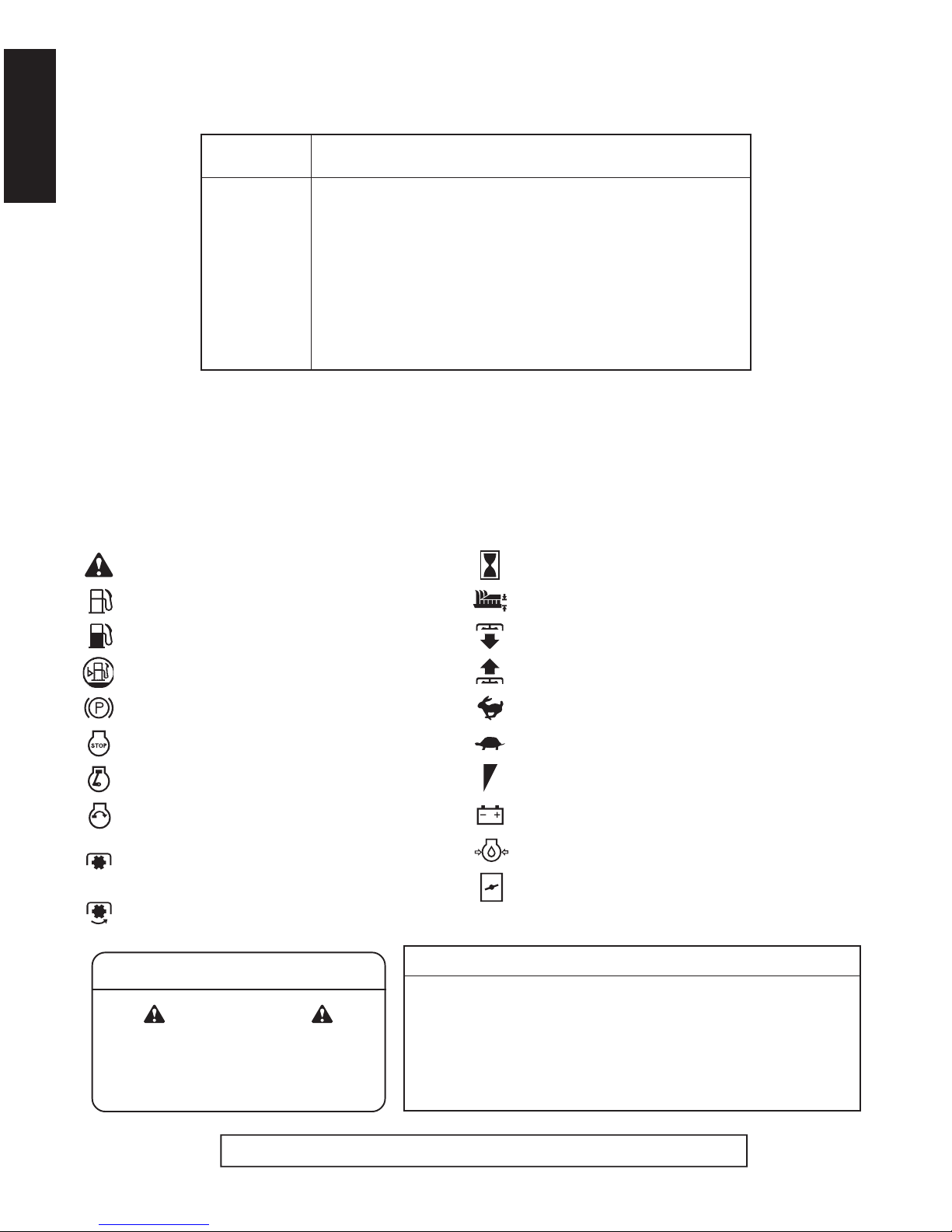
UNIVERSAL SYMBOLS
As a guide to the operation of your machine, various universal symbols have been utilized on the instruments and
controls. The symbols are shown below with an indication of their meaning.
Safety Alert Symbol
Gasoline Fuel
Fuel-Level
Fuel-Level Warning
Parking Brake
Engine-Stop
Engine-Run
Starter Control
Power Take-Off Clutch Control-Off Position
(Disengaged)
Power Take-Off Clutch Control-On Position
(Engaged)
Hours
Cutting Height
Mower-Lowered position
Mower-Raised position
Fast
Slow
Engine Speed Control
Battery
Oil Pressure
Choke
This spark ignition system complies with Canadian ICES-002.
California Proposition 65
WARNING
The engine exhaust from this product
contains chemicals known to the State
of California to cause cancer, birth
defects or other reproductive harm.
IMPORTANT
The engine in this machine is not equipped by the manufacturer
with a standard spark arrester.
It is a violation of California Public Resource Code Section 4442 to
use or operate this engine on or near any forest-covered, brushcovered land, or grass- covered land unless the exhaust system is
equipped with a working spark arrester meeting state laws. Other
states or federal areas may have similar laws.

ENGLISH
FOREWORD
3
SAFETY FIRST
IMPORTANT :
NOTE : Gives helpful information.
3
DANGER :
3
WARNING :
3
CAUTION :
Indicates an imminently hazardous situation which, if not
avoided, will result in death or serious injury.
Indicates a potentially hazardous situation which, if not
avoided, could result in death or serious injury.
Indicates a potentially hazardous situation which, if not
avoided, may result in minor or moderate injury.
Indicates that equipment or property damage could result if
instructions are not followed.
You are now the proud owner of a KUBOTA ZERO TURN MOWER. This machine
is a product of KUBOTA's quality engineering and manufacturing. It is made of
excellent materials and under a rigid quality control system. It will give you long,
satisfactory service. To obtain the best use of your machine, please read this
manual carefully. It will help you become familiar with the operation of the machine
and contains many helpful hints about machine maintenance. It is KUBOTA's policy
to utilize, as quickly as possible, every advance in our research. The immediate use
of new techniques in the manufacturing of products may cause some small parts of
this manual to become outdated. KUBOTA distributors and dealers will have the
most up-to-date information. Please do not hesitate to consult them.
This symbol, the industry's "Safety Alert Symbol", is used throughout this manual
and on labels on the machine itself to warn of the possibility of personal injury.
Read these instructions carefully. It is essential that you read the instructions and
safety regulations before you attempt to assemble or use this unit.

CONTENTS
ENGLISH
SAFE OPERATION.................................................................................................1
SERVICING OF MACHINE .........................................................................................1
SPECIFICATIONS.......................................................................................................3
IMPLEMENT LIMITATIONS........................................................................................6
INSTRUMENT PANEL AND CONTROLS................................................................... 7
BALLAST..................................................................................................................... 9
REAR WEIGHT........................................................................................................9
WEIGHT INSTALLATION........................................................................................9
MOWER MOUNTING................................................................................................10
MOUNTING THE MOWER DECK......................................................................... 10
ADJUSTING THE MOWER ...................................................................................11
DISMOUNTING THE MOWER DECK...................................................................11
OPERATING THE ENGINE.......................................................................................12
MOUNT AND DISMOUNT MACHINE SAFELY..................................................... 12
STARTING THE ENGINE......................................................................................12
Throttle Lever and Choke Knob......................................................................................14
Key Switch......................................................................................................................14
CHECK DURING OPERATING.............................................................................15
Immediately Stop the Engine if:......................................................................................15
Easy Checker (TM).........................................................................................................15
Fuel Gauge.....................................................................................................................15
Coolant Temperature Gauge..........................................................................................16
Fuel Drain.......................................................................................................................16
Fuel Pump ......................................................................................................................16
Fuel Valve.......................................................................................................................17
Hour Meter......................................................................................................................17
COLD WEATHER STARTING............................................................................... 17
WARMING UP .......................................................................................................17
Warm-up and Transmission Oil in the Low Temperature Range....................................17
JUMP STARTING..................................................................................................18
STOPPING THE ENGINE...................................................................................... 19
Engine Stop (By manual)................................................................................................19
OPERATING THE MACHINE....................................................................................20
OPERATING NEW MACHINE...............................................................................20
Changing Lubricating Oil for New Machines...................................................................20
Engine Break-in..............................................................................................................20
Machine Break-in............................................................................................................20
OPERATING FOLDABLE ROPS...........................................................................21
To Fold the ROPS ..........................................................................................................21
To Raise the ROPS to Upright Position..........................................................................22
Adjustment of Foldable ROPS........................................................................................22
STARTING.............................................................................................................23

CONTENTS
ENGLISH
Operator's Seat...............................................................................................................23
Seat Belt.........................................................................................................................24
Hydraulic Lift Control Pedal............................................................................................24
Throttle Lever..................................................................................................................24
Parking Brake Pedal.......................................................................................................25
Motion Control Lever ......................................................................................................25
WORK LIGHT (OPTIONAL KIT)............................................................................28
STOPPING.............................................................................................................28
PARKING............................................................................................................... 28
TRANSPORTING...................................................................................................29
OPERATING THE MOWER......................................................................................30
MAKING THE MOST OF YOUR MOWER.............................................................30
ADJUSTING CUTTING HEIGHT...........................................................................30
OPERATING MOWER...........................................................................................33
PTO Lever ......................................................................................................................33
Starting ...........................................................................................................................33
TIRES AND WHEELS ...............................................................................................34
TIRES.....................................................................................................................34
Inflation Pressure............................................................................................................34
WHEELS................................................................................................................ 34
Remove and Install Front Caster Wheels.......................................................................35
MAINTENANCE.........................................................................................................36
SERVICE INTERVALS ..........................................................................................36
PERIODIC SERVICE CHART LABEL ...................................................................38
LUBRICANTS AND FUEL......................................................................................39
PERIODIC SERVICE.................................................................................................41
HOW TO OPEN THE HOOD AND STEP.............................................................. 41
Hood...............................................................................................................................41
Step ................................................................................................................................41
HOW TO RAISE THE OPERATOR'S SEAT.......................................................... 42
HOW TO OPEN THE LEVER GUIDE.................................................................... 43
LIFT-UP POINT......................................................................................................43
Front side:.......................................................................................................................43
Rear side: .......................................................................................................................43
DAILY CHECK.......................................................................................................44
Checking Engine Oil Level..............................................................................................45
Checking Amount of Fuel and Refueling........................................................................45
Checking and Cleaning Radiator Screen and Bonnet Screen to Prevent Overheating..46
Checking Tire Pressure............................................................................... ........... ........47
Inflation Pressure............................................................................................................47
Checking Transmission Fluid Level................................................................................48
Checking Coolant Level..................................................................................................48
Lubricating All Grease Fittings........................................................................................49
Checking Movable Parts.................................................................................................49
EVERY 50 HOURS................................................................................................ 50
Safety Devices................................................................................................................50
Checking Gear Box Oil Level..........................................................................................51
Greasing.........................................................................................................................52
Oiling...............................................................................................................................54

CONTENTS
ENGLISH
EVERY 100 HOURS.............................................................................................. 55
Changing Engine Oil.......................................................................................................55
Checking Spark Plug Condition & Gap...........................................................................55
Cleaning Air Cleaner Primary Element...........................................................................56
Checking Fuel Lines.......................................................................................................57
Adjusting Fan Drive Belt Tension ...................................................................................59
Adjusting Parking Brake .................................................................................................60
Battery Condition............................................................................................................61
Adjusting Throttle Cable .................................................................................................62
Checking Carbon Canister Air Filter...............................................................................63
EVERY 150 HOURS.............................................................................................. 64
Changing Gear Box Oil...................................................................................................64
EVERY 200 HOURS.............................................................................................. 65
Replacing Engine Oil Filter.............................................................................................65
Checking Radiator Hose and Clamp..............................................................................65
Checking Hydraulic Hose ...............................................................................................66
Replacing Transmission Oil Filter [HST].........................................................................67
Adjusting the Motion Control Lever Pivot........................................................................67
Checking Intake Air Line.................................................................................................68
EVERY 400 HOURS.............................................................................................. 68
Changing Transmission Fluid and Rear Axle Gear Case Oil (RH and LH)....................68
Replacing Hydraulic Oil Filter .........................................................................................69
Replacing Fuel Filter.......................................................................................................70
EVERY 500 HOURS.............................................................................................. 70
Adjusting Engine Valve Clearance.................................................................................70
EVERY AFTER 1000 HOURS...............................................................................70
Cleaning Combustion Chamber......................................................................................70
EVERY 1 YEAR.....................................................................................................70
Replacing Air Cleaner Primary Element and Secondary Element..................................70
Flushing Cooling System and Changing Coolant...........................................................71
Anti-freeze ......................................................................................................................72
EVERY 2 YEARS...................................................................................................73
Replacing Hydraulic Hose ..............................................................................................73
Replacing Fuel Lines......................................................................................................73
Replacing Radiator Hose................................................................................................73
Replacing Mower Gear Box Oil-Seal..............................................................................73
Replacing Intake Air Line................................................................................................73
Replacing Carbon Canister Air Filter..............................................................................73
Replacing One Way Valve..............................................................................................73
Replacing Engine Breather Hose...................................................................................73
SERVICE AS REQUIRED......................................................................................73
Replacing Fuses.............................................................................................................73
Checking and Replacing Blade.......................................................................................74
Mower Belt Replacement................................................................................................76
Bleeding Fuel System.....................................................................................................76
ADJUSTMENT...........................................................................................................77
MOTION CONTROL LEVER .................................................................................77
HST NEUTRAL...............................................................................................................77
MOTION CONTROL LEVER NEUTRAL POSITION......................................................78
MAXIMUM SPEED (FORWARD)...................................................................................78
MOTION CONTROL LEVER ALIGNMENT....................................................................78

CONTENTS
ENGLISH
MOWER DECK LEVEL..........................................................................................79
ANTI-SCALP ROLLERS.................................................................................................79
LEVEL MOWER DECK (Side-to-Side)...........................................................................80
LEVEL MOWER DECK (Front-to-Rear) .........................................................................81
GENERAL TORQUE SPECIFICATION................................................................. 83
TIGHTENING TORQUE CHART...........................................................................84
STORAGE.................................................................................................................85
MACHINE STORAGE............................................................................................ 85
REMOVING THE MACHINE FROM STORAGE.................................................... 85
TROUBLESHOOTING...............................................................................................86
ENGINE TROUBLESHOOTING............................................................................86
BATTERY TROUBLESHOOTING .........................................................................88
MACHINE TROUBLESHOOTING .........................................................................89
MOWER TROUBLESHOOTING............................................................................89
ENGINE EMISSION RELATED INFORMATION....................................................... 91
1SAFE OPERATION
ENGLISH
SAFE OPERATION
Careful operation is your best insurance against an
accident. Read and understand this manual carefully
before operating the machine. All operators, no matter
how much experience they may have had, should read
this and other related manuals before operating the
machine or any implement attached to it. It is the owner's
obligation to instruct all operators in safe operation.
This mowing machine is capable of amputating hands and
feet and throwing objects. Failure to observe the following
safety instructions could result in serious injury or death.
1. The ZERO TURN MOWING MACHINE has different
steering characteristics than other machines with a
steering wheel and does not have a service brake
pedal (but, has a parking brake lock pedal that can be
used to stop the machine in an emergency. Normal
slowing down and stopping is done with the motion
control levers.). Read and understand the operators
manual before operating the machine. Practice
operating machine at low engine speed without mower
engaged in an unobstructed area.
2. Know your equipment and its limitations. Read all
instructions in this manual before attempting to start
and operate the machine.
3. Pay special attention to the danger, warning and
caution labels on the machine itself.
4. KUBOTA recommends the use of a Roll Over
Protective Structures (ROPS) and seat belt in almost
all applications. This combination will reduce the risk
of serious injury or death, should the machine be
upset.
The machine is equipped with a Foldable ROPS,
which may be temporarily folded down only when
absolutely necessary for areas with height constraints.
(There is no operator protection provided by the ROPS
in the folded position. For operator safety the ROPS
should be placed in the upright and locked position
and the seat belt fastened for all other operations.)
If the ROPS is loosened or removed for any reason,
make sure that all parts are reinstalled correctly before
operating the machine.
Never modify or repair a ROPS because welding,
bending, drilling, grinding, or cutting may weaken the
structure.
A damaged ROPS structure must be replaced, not
repaired or revised.
If any structural member of the ROPS is damaged,
replace the entire structure at your local KUBOTA
Dealer.
5. Always use the seat belt when the ROPS is upright. Do
not use the seat belt if the ROPS is down or if there is
no ROPS. Check the seat belt regularly and replace if
frayed or damaged.
6. Do not allow any bystanders around or near machine
during operation.
7. Do not allow passengers, children or non-qualified
operators on the machine at any time. The operator
must remain in the machine seat throughout
operation.
8. Do not operate the machine or any attachments while
under the influence of alcohol, medication, controlled
substances or when fatigued.
9. Do not wear loose, torn, or bulky clothing around
machine. The clothing may catch on moving parts or
controls, leading to the risk of accident. Wear and use
any additional safety items such as hard hat, safety
boots or shoes, eye and hearing protection, gloves,
etc. as appropriate or required.
10.Do not wear radio or music headphones while
operating the machine.
Safe operation requires your full attention.
11. Carefully check the vicinity before operating machine
or any implement attached to it. Clear the work area of
objects (wires, rocks, etc.) that might be picked up and
thrown. Check for overhead clearance which may
interfere with a grass catcher.
12. Check brakes and other mechanical parts for correct
adjustment and wear. Replace worn or damaged parts
promptly. Check the tightness of all nuts and bolts
regularly. (For further details, see "PERIODIC
SERVICE" and "ADJUSTMENT" section.)
13.Keep all shields and guards in place. Replace any that
are damaged or missing.
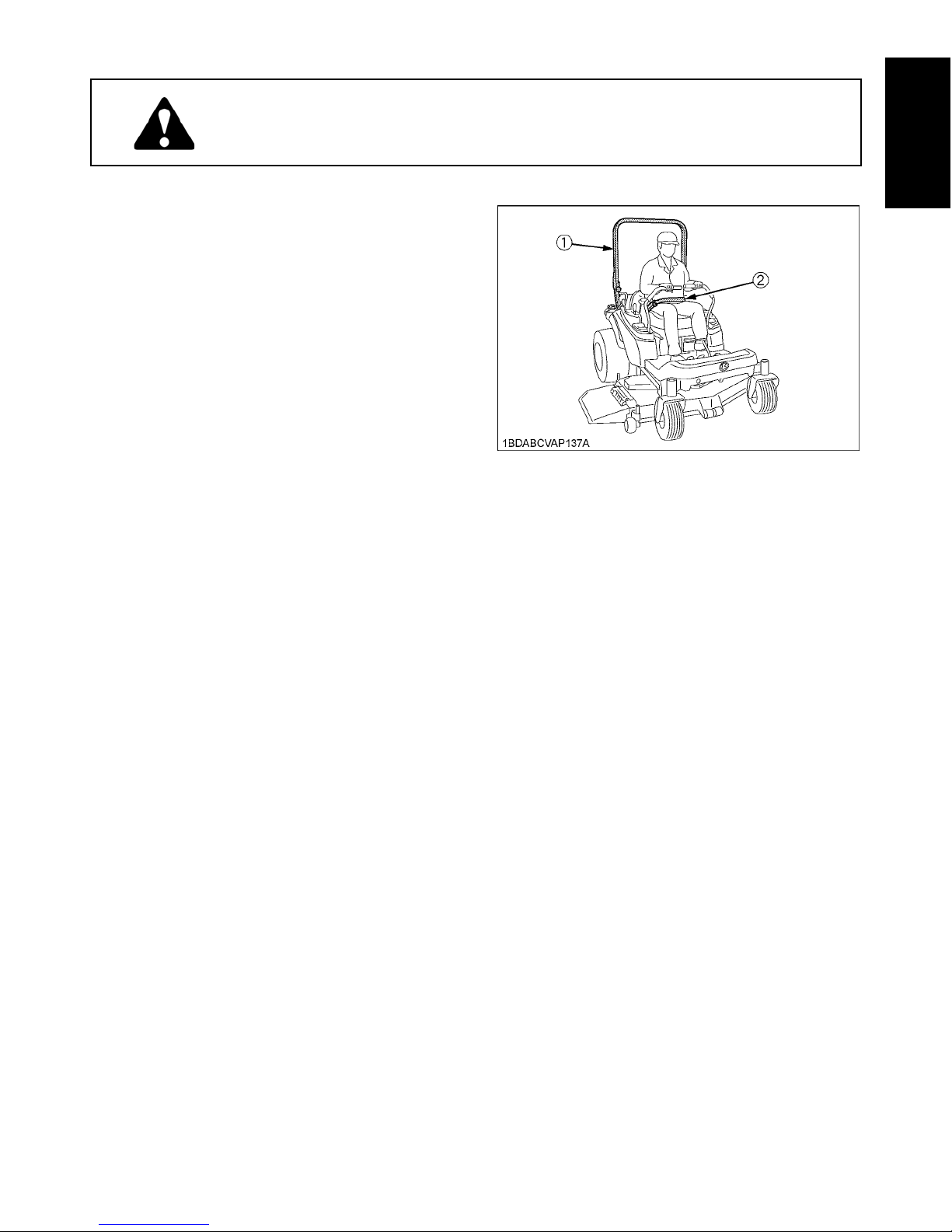
1. BEFORE OPERATING
(1) ROPS
(2) Seat belt

SAFE OPERATION2
ENGLISH
14.Before allowing other people to use your machine,
explain how to operate and have them read this
manual before operation.
15.In addition to the design and configuration of
equipment, hazard control and accident prevention
are dependent upon the awareness, concern and
prudence of personnel involved in the operation,
transport and maintenance of the equipment.
16.Keep the machine and attachments in good operating
condition and keep safety devices in place and in
proper working condition.
17.Do not modify the machine. Unauthorized modification
may affect the function of the machine, which may
result in personal injury.
18.Use only implements approved by KUBOTA. Use
proper ballast to front or rear of machine to reduce the
risk of upsets. Follow the "Safe Operation"
procedures, specified in the manuals with equipment.
19.Keep your machine clean. Accumulations of dirt,
grease, and trash can contribute to fires and lead to
personal injury.
20.The exhaust gas from the muffler is very hot. To
prevent fire, do not expose dry grass, mowed grass, oil
and any other combustible materials to exhaust gas.
Use a spark arrester where required. Also keep the
engine and muffler clean all the time.
C Starting
1. Always sit in the operator's seat when starting engine
or operating levers or controls.
2. Before starting the engine make sure that the motion
control levers are in neutral lock, the parking brake is
applied, and Power Take Off (PTO) is disengaged
(OFF).
3. Do not start engine by shorting across starter
terminals. The machine may start in gear and move if
normal starting circuitry is bypassed.
4. Do not operate or idle engine in a non-ventilated area.
Carbon monoxide gas is colorless, odorless, and
deadly.
5. Do not start engine while tilting deck.
6. Check before each use that operator presence
controls are functioning correctly. Test safety systems.
(See "Safety Devices" in "EVERY 50 HOURS" in
"PERIODIC SERVICE" section.)
Do not operate unless they are functioning correctly.
C Working
1. Do not turn sharply when driving at high speed.
2. To avoid tip over, slow down when turning on uneven
terrain or before stopping.
3. Do not operate near ditches, holes, embankments, or
other terrain, which may collapse under the machine
weight. The risk of machine tip over increases when
the ground is loose or wet.
4. Park the machine on a firm and level surface.
5. Watch where you are going at all times. Watch for and
avoid obstacles. Be alert at curbs, near trees, and
other obstructions and hidden hazards.
6. Know what is behind you before backing up. Look to
the rear before and when backing. Do not mow while
in reverse unless absolutely necessary and make sure
the area immediately behind you is clear of
obstructions or holes and small children. Use extra
caution when machine is equipped with Grass
Catcher. Your view to the rear is restricted.
7. When working in groups, always let others know what
you are doing ahead of time.
8. Do not drive machine on streets or highways. Watch
for traffic when you cross roads or operate near roads.
9. Be aware of the mower discharge direction and do not
point it at anyone.
10. When using any attachments, never direct discharge
material toward bystanders. Do not allow anyone near
the attachments while in operation.
Do not mow when bystanders are present in the
mowing area.
11.To reduce fire hazards, keep the engine exhaust area
free of grass or leaves.
12. Be sure rotating blades and engine are stopped and
the key is removed before placing hands or feet near
blades and cleaning blockages or unclogging chute.
13. Shut the engine off and wait for all movement to stop
before removing grass catcher or unclogging chute.
14.Watch the temperature gauge and maintain all
screens to avoid overheating conditions.
15.Always inspect the mower for damage after striking a
foreign object. Repair or replace any damaged parts
before restarting.
16.Operate during daylight or in bright artificial light.
C Children
Tragic accidents can occur if the operator is not alert to
the presence of children. Children are attracted to the
machine and mowing activity.
Never assume that children will remain where you last
saw them.
1. Keep children out of the mowing area and under the
watchful care of another responsible adult.
2. Be alert and turn machine off if children enter the area.
3. Before and when backing, look behind and down for
small children.
4. Never carry children. There is no safe place for them
to ride. They may fall off and be seriously injured or
interfere with safe machine operation.
5. Never allow children to operate the machine, even
under adult supervision.
6. Use extra care when approaching blind corners,
shrubs, trees, or other obstructions that might hide
children from sight.
7. Do not mow in reverse unless it is absolutely
necessary and make sure area to the rear is clear of
children before doing so.
2. OPERATING

3SAFE OPERATION
ENGLISH
C Operators, age 60 years and above
Data indicates that operators, age 60 years and above,
are involved in a large percentage of machine-related
injuries. These operators should evaluate their ability to
operate the machine safely enough to protect themselves
and others from serious injury.
C Operation on slopes
Slopes are major factor related to loss-of-control and tipover accidents, which can result in severe injury or death.
All slopes require extra caution.
If you cannot back up the slope or if you feel uneasy on it,
do not mow it.
If the engine stops when operating on a slope apply the
parking brake immediately to prevent machine run away.
DO
1. To avoid tip over, operate across the slopes not up and
down. Stay off hills and slopes too steep for safe
operation.
2. Remove obstacles such as rocks, tree limbs, etc.
3. Stay alert for holes in the terrain and other hidden
hazards. Keep away from drop-offs. Uneven terrain
could overturn the machine. Tall grass can hide
obstacles.
4. Follow the manufacturer's recommendations for wheel
weight or counterweights to improve stability.
5. Keep all movement on the slopes slow and gradual.
Do not make sudden changes in speed or direction.
6. Avoid starting or stopping on a slope. If tires lose
traction, disengage PTO and proceed slowly straight
down the slope.
7. Reduce speed and exercise extreme caution on
slopes and in sharp turns to prevent tip-over or loss of
control.
8. Use special caution when changing direction on
slopes. Slow down, and use extra caution when
changing direction on a slope.
DO NOT
1. Do not turn on slopes unless necessary. If necessary,
turn uphill slowly and gradually.
2. Do not mow near drop-offs, ditches, or embankments.
The mower could suddenly turn over if a wheel is over
the edge of cliff or ditch, or if an edge caves in.
3. Do not mow on wet grass. Reduced traction could
cause sliding and loss of control.
4. Do not try to stabilize the machine by putting your foot
on the ground.
5. Do not use grass catcher on steep slopes.
6. Do not start or stop suddenly when going uphill or
downhill. Avoid sudden start and stops on slopes.
7. Never "freewheel". Do not let the machine travel
downhill with motion control levers at neutral lock
position or in neutral.
8. Do not operate machine without the mower deck
installed.
C Stopping
1. Park the machine on level ground.
2. Make sure that the machine and all attachments have
come to a complete stop before dismounting.
3. Before dismounting, apply parking brake, place the
motion control levers in their neutral lock positions,
disengage the PTO, lower all attachments to the
ground, turn off the engine, and remove the key.
4. Do not park the machine on dry grass or leaves.
1. Before installing or using PTO-driven equipment, read
the manufacturer's manual and review the safety
labels attached to the equipment.
2. Wait until all moving components have completely
stopped before connecting, disconnecting, adjusting,
cleaning, or servicing any PTO-driven equipment.
3. Use the PTO with KUBOTA approved attachments.
The speed of PTO:
ZG332 2400 rpm at 3200 engine rpm
1. Use lift link only with authorized attachments designed
for lift link usage.
1. Disengage power to attachment(s) when transporting
or not in use.
2. Do not tow this machine. Use a suitable truck or trailer
when transporting on public roads.
3. Use extra care when loading or unloading the machine
into a trailer or truck.
4. This machine is not allowed to be used on public
roads.
3. USING THE PTO
4. USING THE LIFT LINK
5. TRANSPORTING
SAFE OPERATION4
ENGLISH
C Servicing
1. Before servicing, park the machine on a firm, level
surface and apply the parking brake. Remove the key
to prevent accidental start-up.
2. Allow the machine time to cool before touching the
engine, muffler, radiator, etc.
3. Always stop the engine before refueling. Avoid spills
and overfilling. Wipe up spilled fuel immediately.
4. Use extra care in handling gasoline fuels. They are
flammable.
(1) Use only an approved container.
(2) Do not remove fuel cap or refuel with the engine
running. Allow engine to cool before refueling. Do
not smoke while refueling or when standing near
fuel.
(3) Do not refuel the machine indoors and always
clean up spilled fuel or oil.
(4) Do not store the machine or fuel container inside
where there is an open flame, such as in a water
heater.
5. Do not smoke when working around battery or when
refueling. Keep all sparks and flames away from
battery and fuel tank.
A battery, especially when charging, will give off
hydrogen and oxygen gases, which can explode and
cause serious personal injury.
6. Before "jump starting" a dead battery, read and follow
all the instructions.
7. Disconnect the battery's ground cable before working
on or near electric components.
8. Do not use or charge the refillable type battery if the
fluid level is below the LOWER (lower limit level) mark.
Otherwise, the battery component parts may
prematurely deteriorate, which may shorten the
battery's service life or cause an explosion. Check the
fluid level regularly and add distilled water as required
so that the fluid level is between the UPPER and
LOWER levels.
9. Keep first aid kit and fire extinguisher handy at all
times.
10. Do not remove the radiator cap while coolant is hot.
When cool, slowly rotate cap to the first stop and allow
sufficient time for excess pressure to escape before
removing the cap completely. If the machine has a
coolant recovery tank, add coolant there instead of the
radiator.
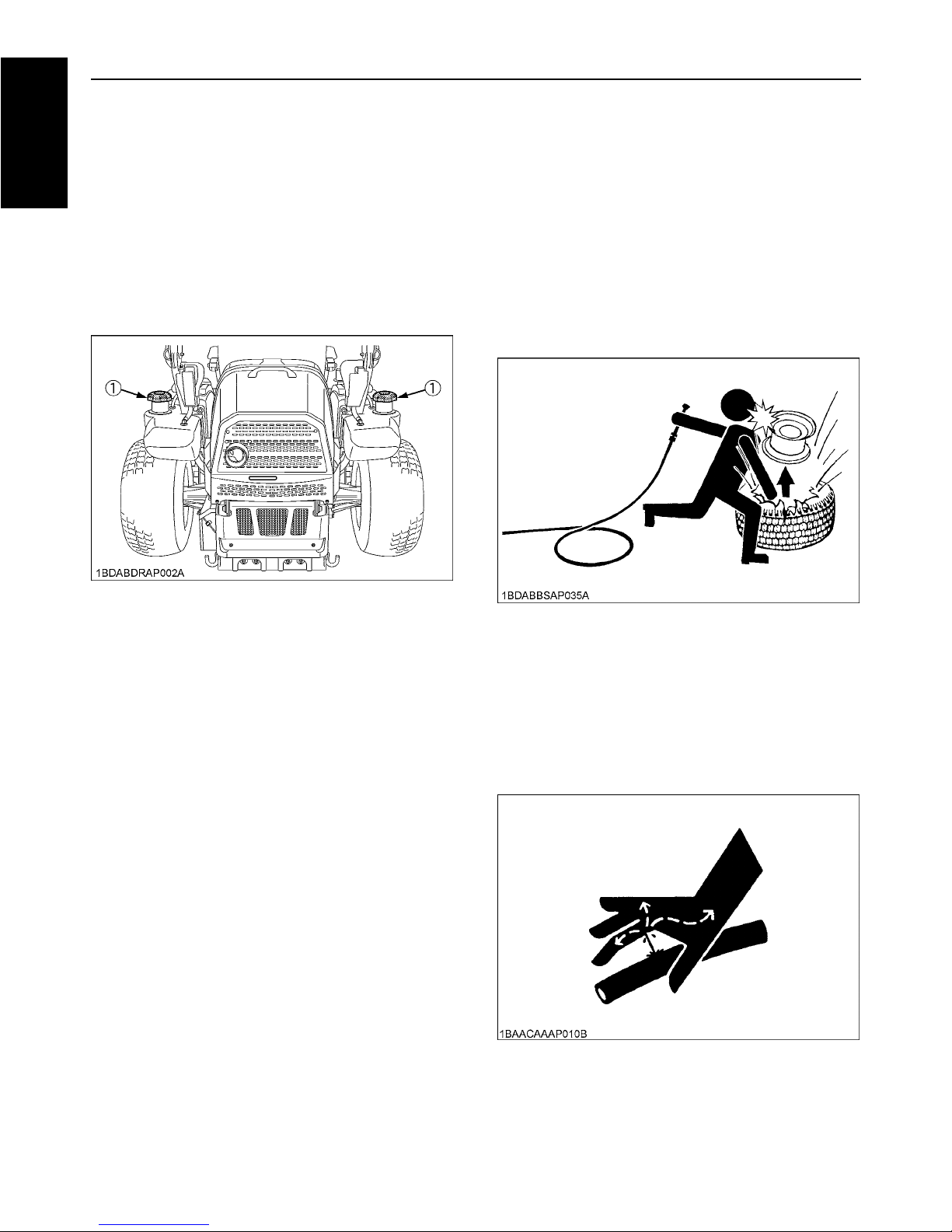
11.Do not attempt to mount a tire on a rim unless qualified
to do so and all proper safety precautions are followed.
12.Always maintain the correct tire inflation pressure. Do
not inflate tires above the recommended pressure
shown in the Operator's Manual.
13.Provide adequate support when changing wheels.
14.Make sure that wheel nuts and bolts have been
tightened to the specified torque.
15.Escaping hydraulic fluid under pressure has sufficient
force to penetrate the skin causing serious personal
injury. Before disconnecting lines, be sure to relieve all
pressure. Before applying pressure to the system,
make sure all connections are tight and that lines,
pipes, and hoses are not damaged.
6. SERVICING AND STORAGE
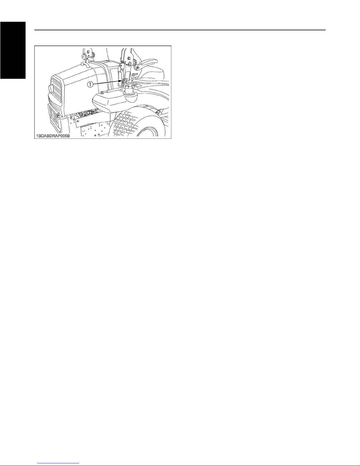
(1) Fuel tank cap
5SAFE OPERATION
ENGLISH
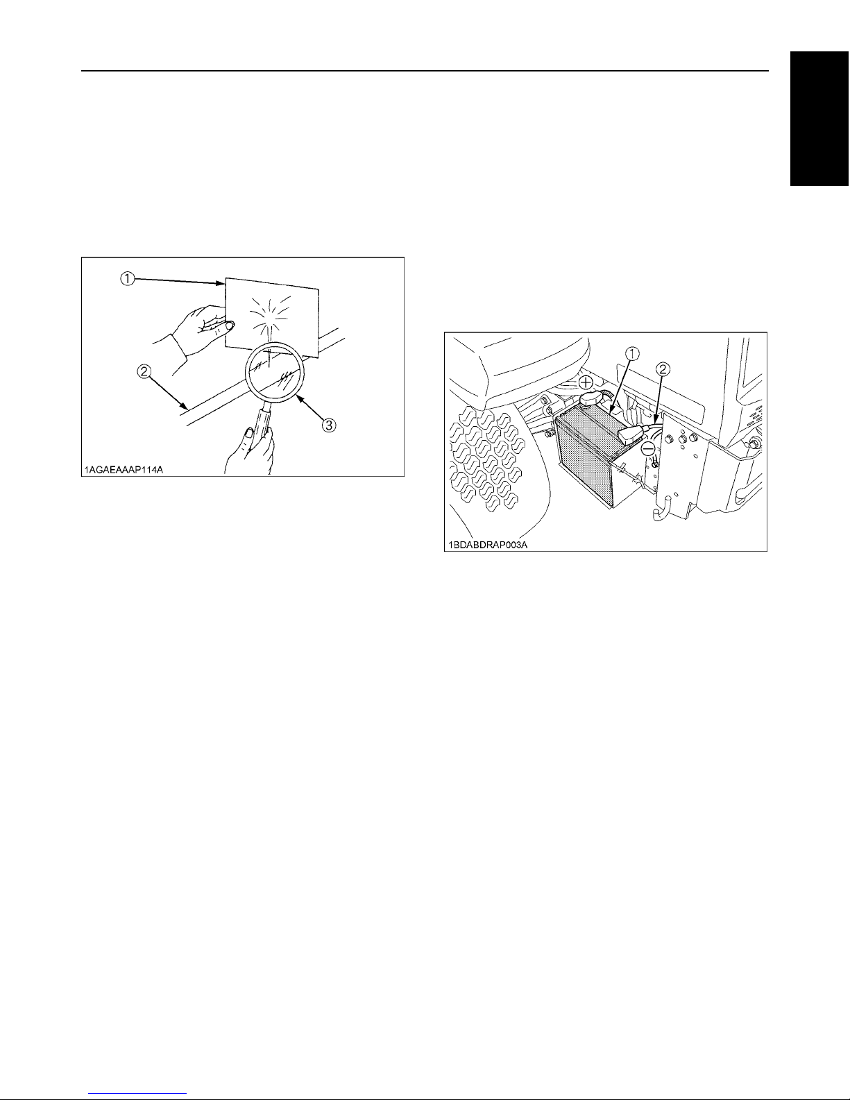
16. Fluid escaping from pinholes may be invisible. Use a
piece of cardboard or wood to search for suspected
leaks: do not use hands. Use safety goggles or other
eye protection.
If injured by escaping fluid, see a medical doctor at
once. Serious infection or reaction will result if proper
medical treatment is not administered immediately.
This fluid can produce gangrene or severe allergic
reaction.
17. Do not make adjustments or repairs with the engine
running.
18. Keep machine free of grass, leaves, or other debris
build-up.
19.Do not change the engine governor setting or
overspeed the engine.
20.Do not run a machine inside a closed area.
21.Mower blades are sharp and can cut your hands. Wrap
the blade(s) or wear gloves, and use extra caution
when servicing them.
22.Keep nuts and bolts, especially blade attachment
bolts, tight and keep equipment in good condition.
23.Never tamper with safety devices. Check their
operation for proper function regularly.
24.Waste products such as used oil, fuel, coolant, brake
fluid, and batteries, can harm the environment, people,
pets and wildlife. Please dispose of properly.
25. Do not use beverage containers for waste fluids or
other products. Someone, particularly children, may
drink them by mistake.
26. Securely support machine or any machine elements
with stands or suitable blocking before working
underneath. For your safety do not rely on
hydraulically supported devices, they may leak down,
suddenly drop or be accidently lowered.
27.See your local Recycling Center or KUBOTA Dealer to
learn how to recycle or get rid of waste products.
A A Material Safety Data Sheet (MSDS) provides
specific details on chemical products; physical and
health hazards, safety procedures, and emergency
response techniques. The seller of the chemical
products used with your machine is responsible for
providing the MSDS for that product upon request.
C Storage
1. Keep the machine and supply of fuel in locked storage
and remove the ignition key to prevent children or
others from playing or tampering with them.
2. To avoid sparks from an accidental short circuit,
always disconnect the battery's ground cable (-) first
and reconnect it last.
3. To avoid the danger of exhaust fume poisoning, do not
operate the engine in a closed building without
adequate ventilation.
4. To reduce fire hazards, clean the machine thoroughly
before storage. Dry grass and leaves around the
engine and muffler may ignite.
(1) Cardboard
(2) Hydraulic line
(3) Magnifying glass
(1) Battery
(2) Ground cable
(+): Positive terminal
(-): Negative terminal
SAFE OPERATION6
ENGLISH
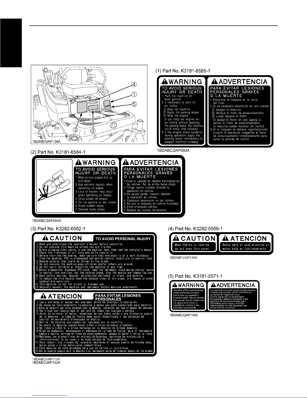
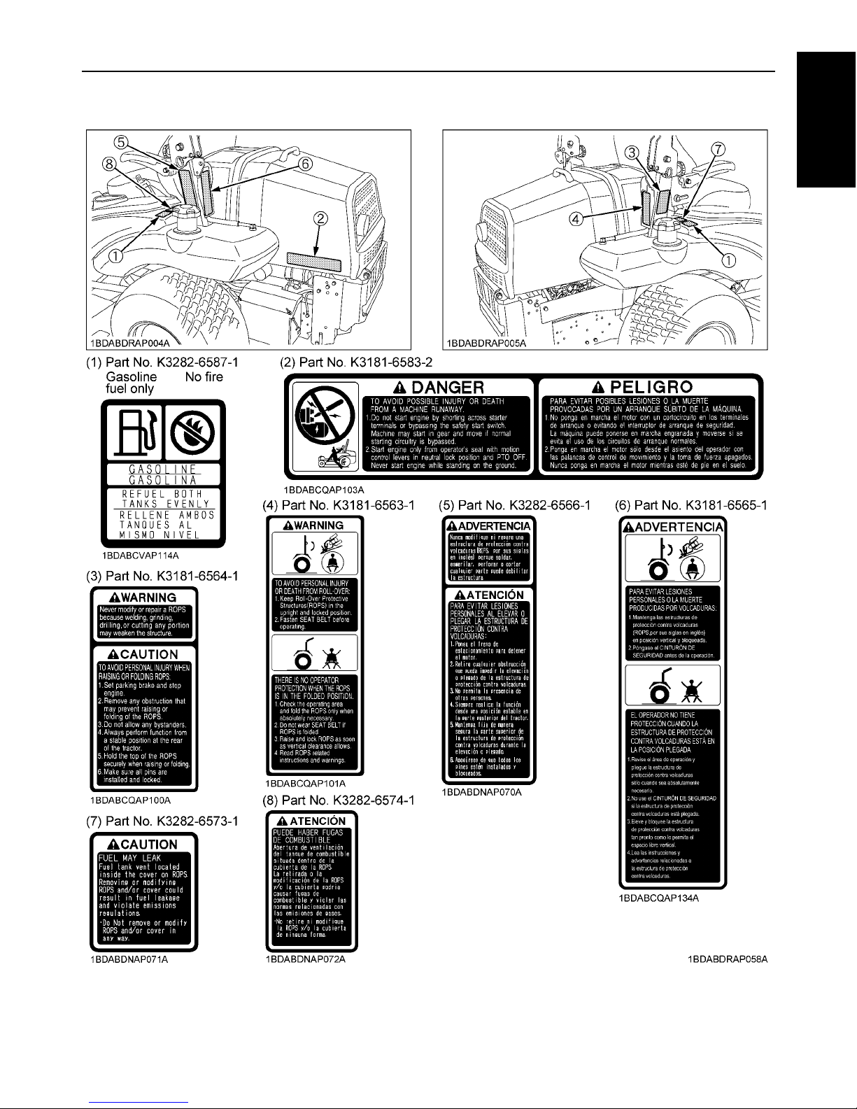
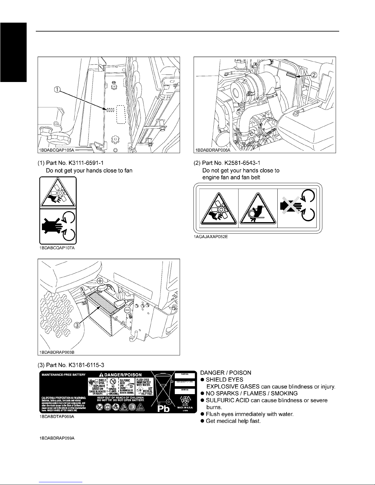
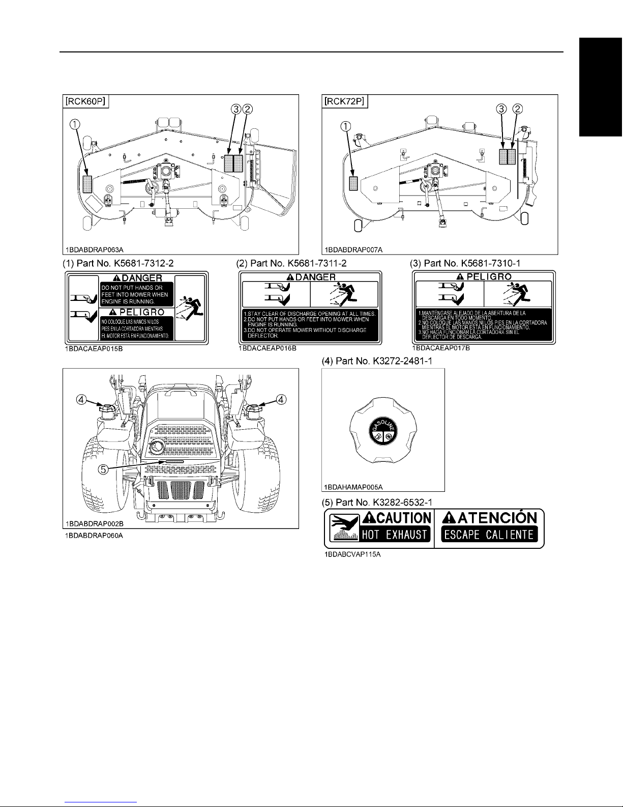
7. DANGER, WARNING AND CAUTION LABELS
7SAFE OPERATION
ENGLISH
SAFE OPERATION8
ENGLISH
9SAFE OPERATION
ENGLISH
1. Keep danger, warning and caution labels clean and free from obstructing material.
2. Clean danger, warning and caution labels with soap and water, and dry with a soft cloth.
3. Replace damaged or missing danger, warning and caution labels with new labels from your local KUBOTA Dealer.
4. If a component with danger, warning and caution label(s) affixed is replaced with new part, make sure new label(s) is
(are) attached in the same location(s) as the replaced component.
5. Mount new danger, warning and caution labels by applying on a clean dry surface and pressing any bubbles to outside
edge.
8. CARE OF DANGER, WARNING, AND CAUTION LABELS

1SERVICING OF MACHINE
ENGLISH
SERVICING OF MACHINE
After reading this manual thoroughly, you will find that you
can do some of the regular maintenance yourself. Your
dealer is interested in helping you get the best
performance from your new machine and wants to help
you get the most value from it. When in need of parts or
major service, be sure to see your KUBOTA Dealer. When
in need of parts, be prepared to give your dealer the
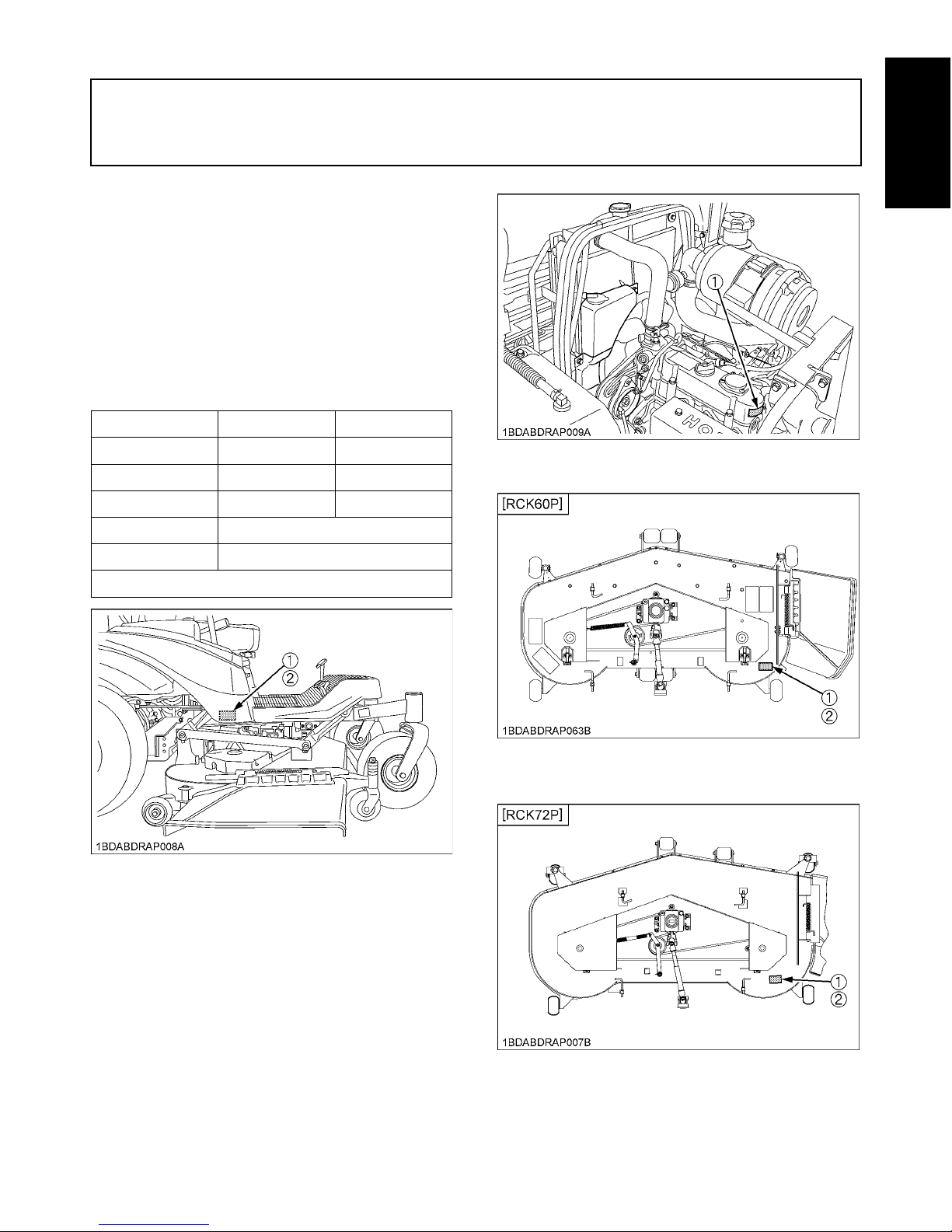
machine, engine and mower serial numbers.
Locate the serial numbers now and record them in the
space provided.
Type Serial No.
Machine
Engine
Mower
Date of Purchase
Name of Dealer
(To be filled in by purchaser)
(1) Machine identification plate
(2) Machine serial No.
(1) Engine serial No.
(1) Mower identification plate
(2) Mower serial No.
(1) Mower identification plate
(2) Mower serial No.
SERVICING OF MACHINE2
ENGLISH
(1) ROPS serial No.

3SPECIFICATIONS
ENGLISH
SPECIFICATIONS
Model ZG332P ZG332LP
Engine
Model WG972-G-E3-ZG-1
Max. engine power (Gross) kW (HP) 24.2 (32.5) (*1)
Type Liquid-cooled gasoline engine
Number of cylinders 3
Bore and stroke mm (in.)
74.5 x 73.6
(2.93 x 2.90)
Total displacement cm (cu. in.) 962 (58.7)
Fuel Automobile unleaded or regular ga soline
Starter Electric starter with battery
Lubrication Forced lubrication by gear pump
Cooling Liquid with pressurized radiator
Battery 51R (12 V, RC: 70 min, CCA: 475A)
Capacities
Fuel tank L (U.S.gals.) 49 (12.9)
Engine crankcase
(with filter)
L (U.S.qts.) 3.5 (3.7)
Engine coolant L (U.S.qts.) 2.7 (2.85)
Recovery tank L (U.S.qts.) 0.25 (0.26)
Transmission case including
Rear axle gear case
L (U.S.qts.) 12.1 (12.8) (*3)
Dimensions
Overall length mm (in.) 2329 (91.7) 2414 (95.0)
Overall width
w/o mower deck
mm (in.) 1460 (57.5)
Overall
height
With ROPS upright mm (in.) 1915 (75.4)
With ROPS folded mm (in.) 1645 (64.8)
Wheelbase mm (in.) 1410 (55.5) 1495 (58.8)
Min. ground clearance mm (in.)
130 (5.12)
W/60", W/72"
Tread
Front mm (in.) 975 (38.4) 1070 (42.1)
Rear mm (in.) 1150 (45.3)
Weight
(W/MOWER DECK)
kg (lbs.) 749 (1651) with 60" 800 (1763) with 72"
Traveling
system
Tires
Front 15 x 6.0 - 6 (Semi-pneumatic Non Flat Tire) Rib
Rear 26 x 12.0 - 12 (4PR) Turf
Traveling
speeds *2
Forward mph (km/h) 0 to 10.6 (0 to 17.0) (*2)
Reverse mph (km/h) 0 to 5.3 (0 to 8.5) (*2)
Steering 2 - Hand levers
Transmission 2 - HST w / Gear
Parking brake Wet multi disk / Foot applied, released
Min. turning radius mm (in.) 0 (0)

4 SPECIFICATIONS
ENGLISH
PTO
Revolution
1 speed
(2400 rpm at 3200 engine rpm)
Drive system Shaft drive, KUBOTA 10 tooth involute spline
Clutch type Wet multi disks
PTO brake Wet single disk
(Specifications and design subject to change without notice)
NOTE:
*1: Manufacturer's estimate
*2: At 3200 engine rpm
*3: Oil amount when the oil level is at the upper level.
Model ZG332P ZG332LP

5SPECIFICATIONS
ENGLISH
*1: Engine Max rpm
Model RCK60P-327Z RCK72P-332Z
PRO Commercial Deck
(Fabricated deck)
Suitable machine ZG332P ZG332LP
Mounting method Quick joint, Parallel linkage
Adjustment of cutting height Dial gauge
Cutting width mm (in.) 1524 (60.0) 1829 (72.0)
Cutting height mm (in.) 25 to 127 (1.0 to 5.0)
Weight (Approx.) kg (lbs.) 143 (315) 165 (364)
Blade spindle speed r/s (rpm) 56.0 (3360) *1 47.2 (2830) *1
Blade tip velocity m/s (fpm) 92.0 (18100) *1 92.6 (18200) *1
Blade length mm (in.) 523 (20.6) 625 (24.6)
Number of blades 3
Dimensions
Total length mm (in.) 1002 (39.4) 1170 (46.1)
Total width mm (in.) 1911 (75.2) 2224 (87.6)
Total height mm (in.) 358 (14.1)
6 IMPLEMENT LIMITATIONS
ENGLISH
IMPLEMENT LIMITATIONS
The KUBOTA Machine has been thoroughly tested for proper performance with implements sold or approved by KUBOTA.
Use with implements which are not sold or approved by KUBOTA and which exceed the maximum specifications listed
below, or which are otherwise unfit for use with the KUBOTA Machine may result in malfunctions or failures of the machine,
damage to other property and injury to the operator or others. [Any malfunctions or failures of the machine resulting from
use with improper implements are not covered by the warranty.]
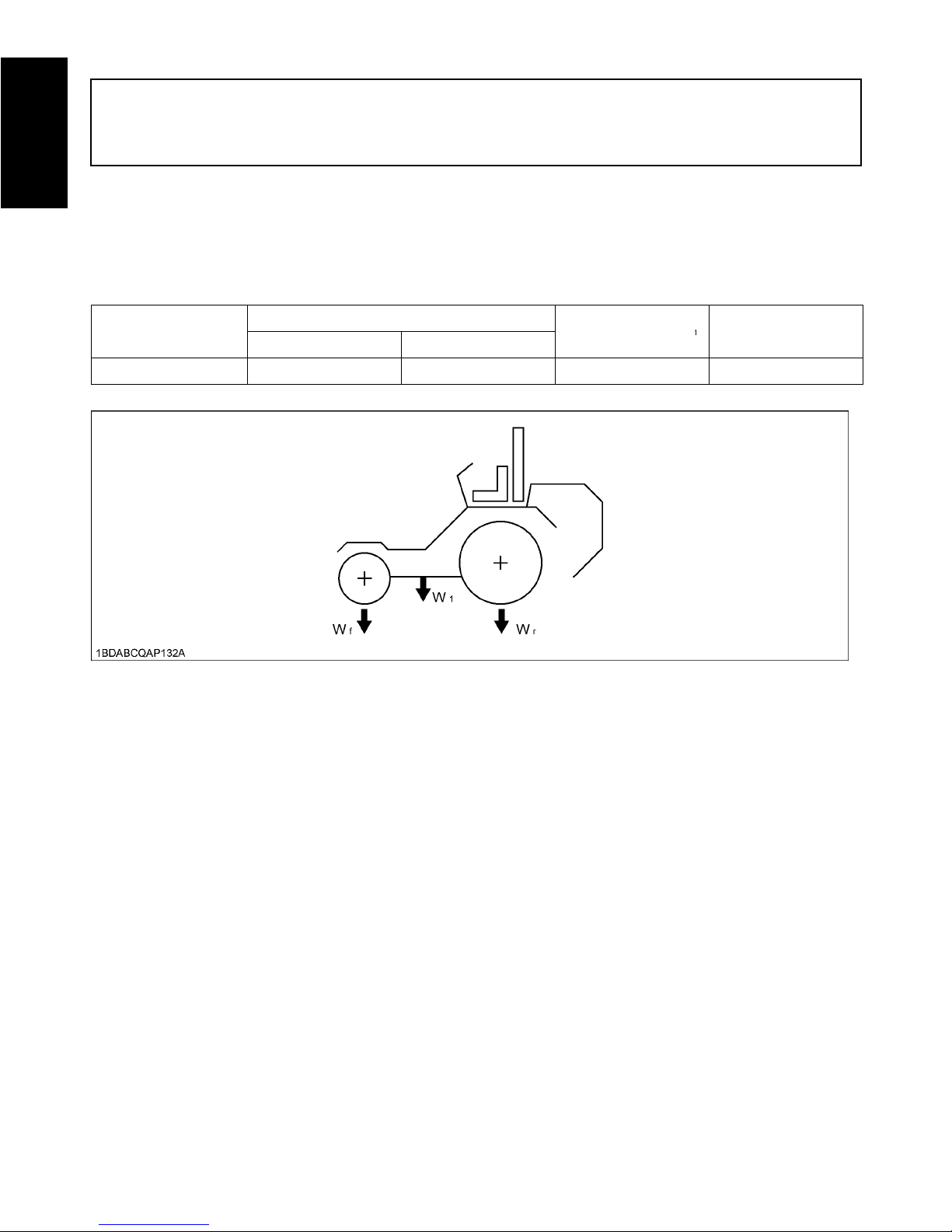
Maximum loading weight
Implement weight W Maximum total weight
Front axle Wf Rear axle Wr
ZG332P, ZG332LP 250 kg (551 lbs.) 870 kg (1918 lbs.) 315 kg (694 lbs.) 1120 kg (2469 lbs.)
7INSTRUMENT PANEL AND CONTROLS
ENGLISH
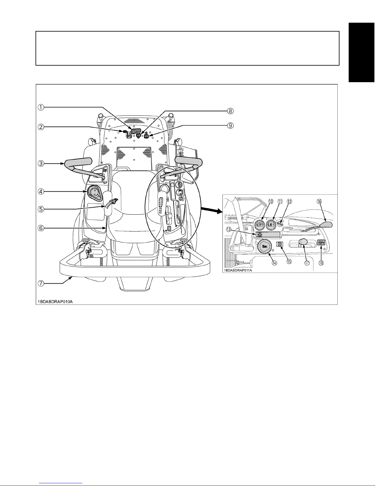
INSTRUMENT PANEL AND CONTROLS
ILLUSTRATED CONTENTS ILLUSTRATED CONTENTS
(1) Parking brake pedal............................. 12, 25 (10) Coolant temperature gauge.................. 16
(2) Parking brake lock pedal...................... 12, 25 (11) Fuel gauge (LH tank only)..................... 15
(3) Motion control lever.............................. 12, 25 (12) Key switch............................................ 14
(4) Cup holder............................................ - (13) Easy checker (TM)............................... 15
(5) Seat belt............................................... 24 (14) Cutting height control dial..................... 30
(6) Operator's seat..................................... 23 (15) Choke knob.......................................... 14
(7) ROPS................................................... 21 (16) PTO lever............................................. 33
(8) Hydraulic lift control pedal (DOWN)...... 24 (17) Throttle lever........................................ 24
(9) Hydraulic lift control pedal (UP)............ 24 (18) Hour meter........................................... 17
INSTRUMENT PANEL AND CONTROLS8
ENGLISH
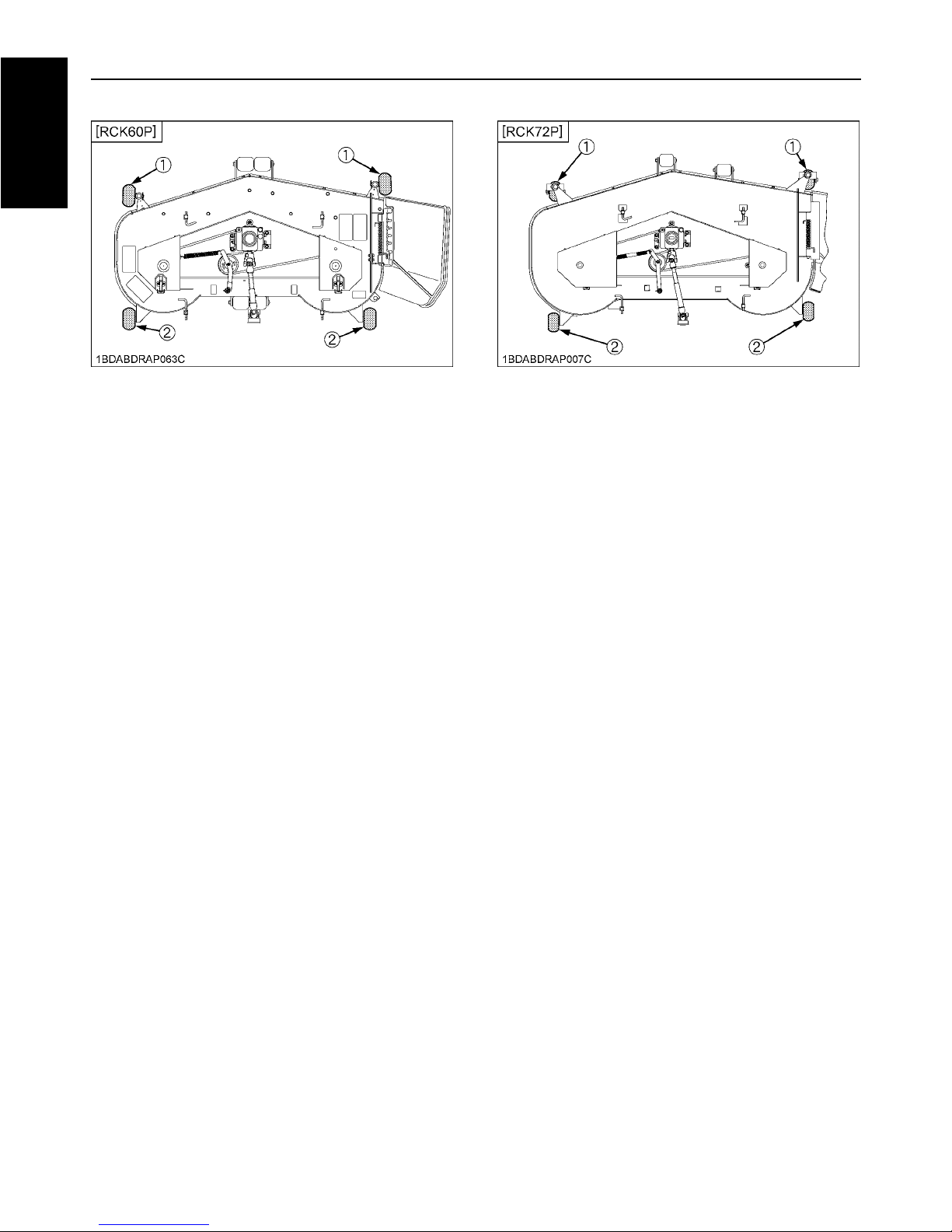
ILLUSTRATED CONTENTS
(1) Anti-scalp roller (Front, pin shift type)...... 30
(2) Anti-scalp roller (Rear, bolt shift type)...... 30
ILLUSTRATED CONTENTS
(1) Anti-scalp roller (Front, swivel type).......... 30
(2) Anti-scalp roller (Rear, bolt shift type)........ 30
9BALLAST
ENGLISH
BALLAST
REAR WEIGHT
To avoid serious injury or death:
A Ballast is required for operating this machine.
Wrong weight combination will cause machine
instability. Add required weight to maintain
stability and avoid tipover. See requirements
listed on the weight combination chart.
A If weight is disassembled for servicing or
installing options, make sure that the required
weight must be assembled again before using
the machine.
Requirement weight combination chart
Rear frame weight must be installed as shown in the
figure below when utilizing each combination. (See
requirement weight combination chart.)
WEIGHT INSTALLATION
To avoid personal injury:
A Park the machine on a firm and level surface.
A Apply the parking brake.
A Stop the engine and remove the key.
1. Before operating the machine, raise the lift links to the
full raised position.
2. Adjust the cutting height control dial to lowest position.
Set the mower deck to the lowest position.
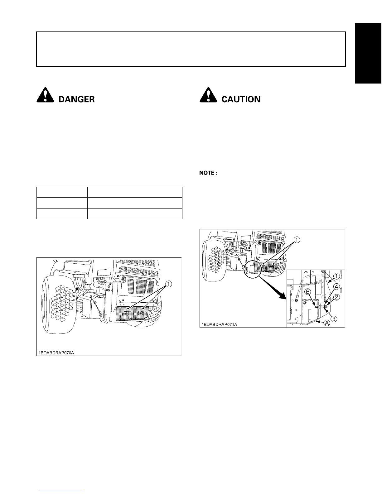
A Make sure that the number of weights is matched to
the model name.
3. Install the required weight (1) to the bracket (A) of
frame with M10 nuts (2), spring washers (3) and plain
washers (4). (See "TIGHTENING TORQUE CHART"
in "ADJUSTMENT" section.)
Machine Model Weight quantity
ZG332P 0
ZG332LP 2
(1) Weight
(1) Weight
(2) M10 nut
(3) Spring washer
(4) Plain washer
(A) Bracket of frame
(B) Stud bolt
10 MOWER MOUNTING
ENGLISH
MOWER MOUNTING
MOUNTING THE MOWER DECK
To avoid personal injury:
A Park the machine on a firm and level surface.
A Apply the parking brake.
A Stop the engine and remove the key.
1. Before mounting the mower deck, raise the lift links to
the full up position.
2. Adjust the cutting height control dial to 1 in. position.
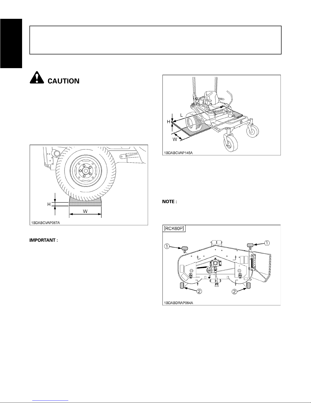
3. Go backward so that right and left rear tires would be
on the board 40 mm (1.57 in.) high.
A Use a board more than 300 mm (11.8 in.) wide and
1400 mm (55.1 in.) long.
A Make sure that right and left rear tires are firm on the
board.
4. Change the direction of the front tires as shown in the
figure.
5. Place the mower deck at the right side of the machine.
6. Slide the mower deck under the machine, and make
sure that the mower gear case is placed properly in the
center of the machine.
A For easy installation set the anti scalp roller as shown
below.
RCK60P: Two places front (Rear, bolt shift type)
H: 40 mm (1.57 in.) W: 300 mm (11.8 in.)
H: 40 mm (1.57 in.)
L: 1400 mm (55.1 in.)
W: 300 mm (11.8 in.)
(1) Anti scalp roller (pin shift type)
(2) Anti scalp roller (bolt shift type)
11MOWER MOUNTING
ENGLISH
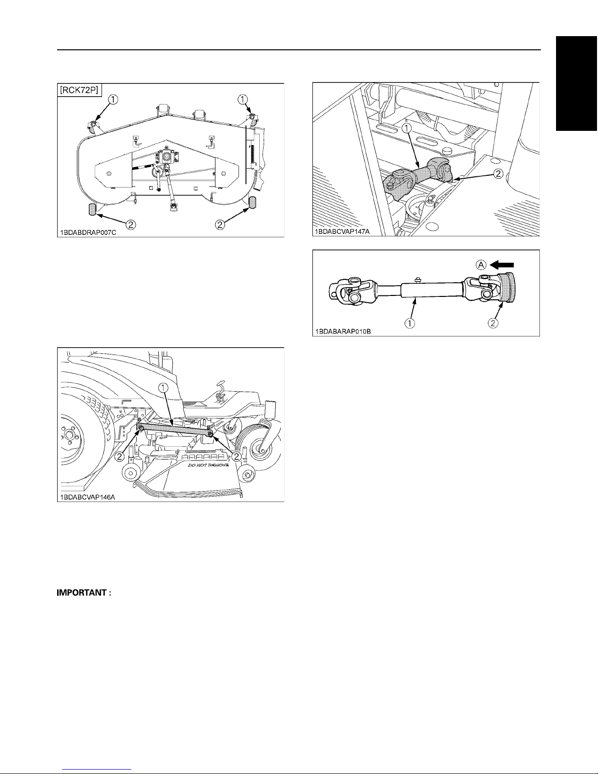
RCK72P: No places*
*No roller that should turn in the direction
7. Depress the hydraulic lift control pedal (DOWN) and
pull down the lift links.
8. Attach the lift links to the mower deck with attaching
hardwares.
9. Install universal joint.
Pull back the coupler of the universal joint.
Push the universal joint onto the PTO shaft until the
coupler locks.
A Tug the universal joint backward and forward to make
sure it is locked securely.
10. After mounting the mower, check the mower level. If
necessary, adjust the mower level and anti-scalp
rollers.
ADJUSTING THE MOWER
See "OPERATING THE MOWER" section.
DISMOUNTING THE MOWER DECK
For dismounting the mower deck, reverse the above
procedures.
(1) Anti scalp roller (Front, swivel type)
(2) Anti scalp roller (Rear, bolt shift type)
(1) Lift link
(2) Clevis pin, Plain washer, Snap ring
(1) Universal joint
(2) Coupler
(A) "PULL"
12 OPERATING THE ENGINE
ENGLISH
OPERATING THE ENGINE
To avoid personal injury:
A Read "SAFE OPERATION" in the front of this
manual.
A Read the danger, warning and caution labels
located on the machine.
A To avoid danger of exhaust fume poisoning, do
not operate the engine in a closed building
without proper ventilation.
A Never start the engine while standing on the
ground. Start the engine only from operator's
seat.
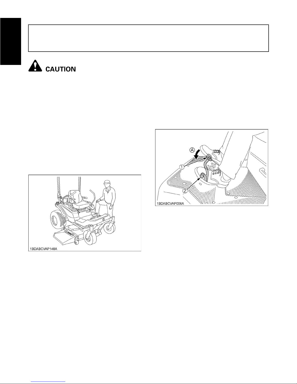
MOUNT AND DISMOUNT MACHINE
SAFELY
DO NOT step on either side of the mower deck when
mounting and dismounting the machine. When mounting
the machine from either side, step over the mower deck.
STARTING THE ENGINE
To apply the parking brake:
Depress the parking brake pedal firmly with your right
foot and the parking brake lock pedal simultaneously
with your left foot. Then release the parking brake
pedal while holding the parking brake lock pedal down.
To release the parking brake:
Depress the brake pedal and release slowly with your
right foot without pressing the parking brake lock
pedal.
1. Sit on the operator's seat.
2. Apply the parking brake.
(1) Parking brake pedal
(2) Parking brake lock pedal
(A) "DEPRESS"
13OPERATING THE ENGINE
ENGLISH
A If the engine is cold:
Pull the choke knob out.
A If the engine is warm:
Place the throttle control lever midway between the
"SLOW" and the "FAST" positions.
A Do not depress the hydraulic lift control pedal.
When the engine is off, depressing the hydraulic lift
control pedal (UP or DOWN) will lower the implement.
A Because of the start interlocks, the engine can not be
started except when the PTO clutch is disengaged
(OFF), the parking brake lock pedal is applied, motion
control levers are in "NEUTRAL LOCK" position and
the operator is sitting on the seat.
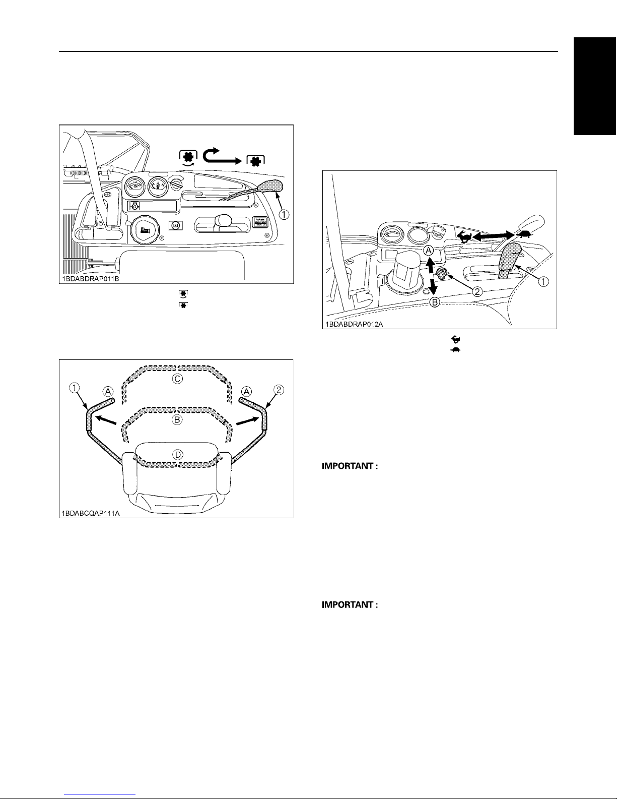
3. Make sure that the PTO lever is in the
"DISENGAGED" (OFF) position.
(1) PTO lever "ENGAGED" (ON)
"DISENGAGED" (OFF)
4. Place the motion control levers in the
"NEUTRAL LOCK" position.
(1) Motion control lever (LH)
(2) Motion control lever (RH)
(A) "NEUTRAL LOCK"
Position
(B) "NEUTRAL" Position
(C) "FORWARD"
(D) "REVERSE"
5. Set the throttle lever as follows.
(1) Throttle lever
(2) Choke knob
(A) Pull out: "ON" position
(B) Push in: "OFF" position
"FAST"
"SLOW"
6. Insert the key into the key switch and
turn clockwise one notch.
Make sure the Easy Checker (TM) lights
are ON.
7. Turn the key switch to the "START"
position and release the key to the "ON"
position when the engine starts.
 Loading...