

Kubota ZD21N-EC, ZD21-EC, ZD28-EC Workshop Manual

WORKSHOP MANUAL
KiSC issued 09, 2006 A
ZERO TURN MOWER
ZD21N-EC,ZD21-EC,ZD28-EC

TO THE READER
KiSC issued 09, 2006 A
This WORKSHOP MANUAL has been prepared to provide servicing personnel with
information on th e mechan ism, ser vice an d mai ntenance of Z D21N-EC, Z D21- EC an d
ZD28-EC KUBOTA ZD Series Zero Turn Mower. It is divided into two parts,
“MECHANISM” and “SERVICING” for each section except “ENGINE” section.
■ Mechanism
Information on the cons truction and fu nction are inclu ded. This info rmation shoul d
be understood before proceeding with troubleshooting, disassembling and servicing.
■ Servicing
The heading “GENERAL” includes general precautions, check and maintenance and
special tools. Other section, there are troubleshooting, servicing specification lists,
checking and adjusting, disassembling and assembling, and servicing which cover
procedures, precautions, factory specifications and allowable limits.
All information illustrations and specifications contained in this manual are based on
the latest product information available at the time of publication.
The right is reserved to make changes in all information at any time without notice.
April 2004
© KUBOTA Corporation 2004
ZD21N-EC, ZD21-EC, ZD28-EC, WSM
SAFETY FIRST
KiSC issued 09, 2006 A
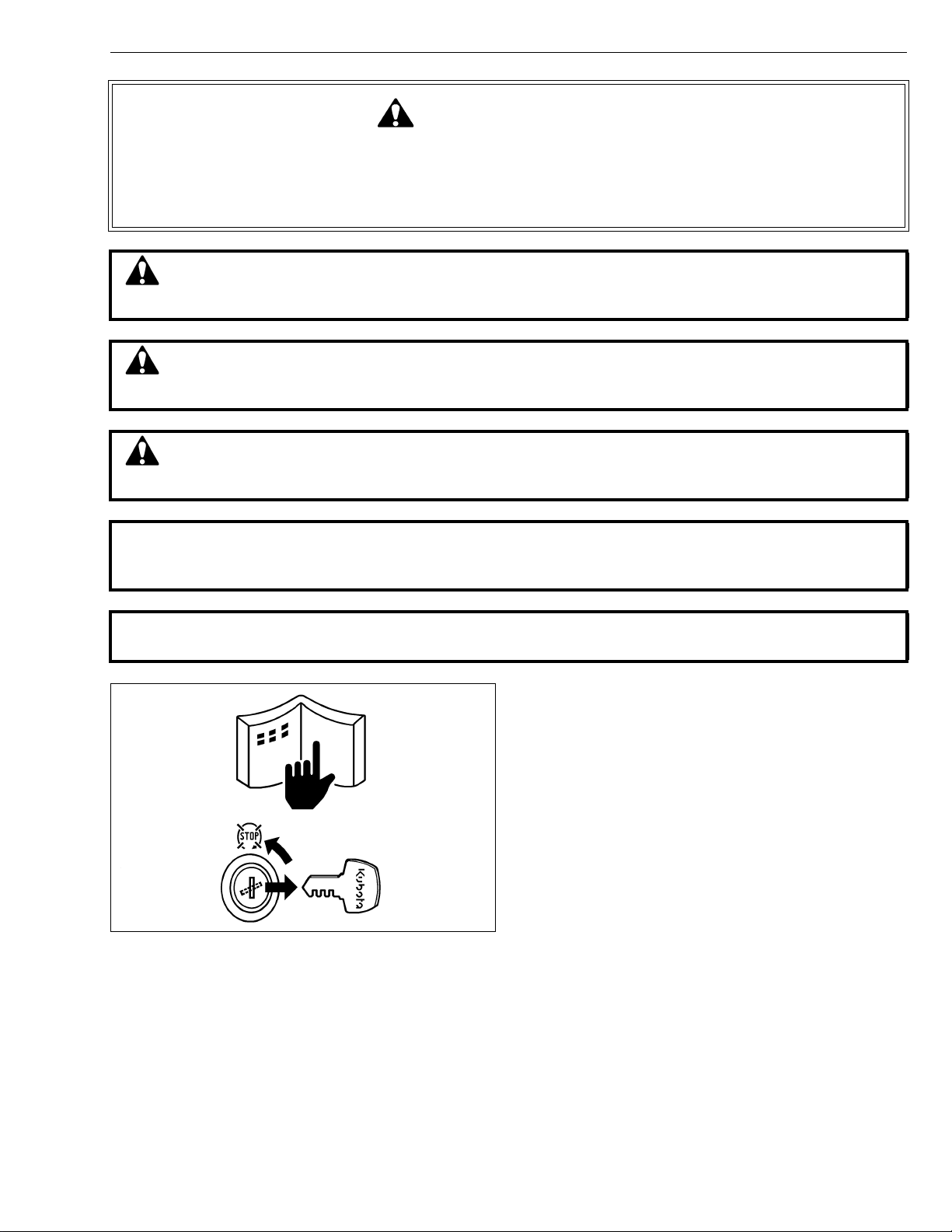
SAFETY INSTRUCTIONS
SAFETY INSTRUCTIONS
This symbol, the industry’s “Safety Alert Symbol”, is used throughout this manual and on labels on
the machine itself to warn of the possibility of personal injury. Read these instructions carefully.
It is essential that you read the instructions and safety regulations before you attempt to repair or use
this unit.
DANGER : Indicates an imminently hazardous situation which, if not avoided, will result in
death or serious injury.
WARNING : Indicates a potentially hazardous situation which, if not avoided, could result in
death or serious injury.
CAUTION : Indicates a potentially hazardous situation which, if not avoided, may result in
minor or moderate injury.
■ IMPORTANT : Indicates that equipment or property damage could result if instructions are not
followed.
■ NOTE : Gives helpful information.
BEFORE SERVICING AND REPAIRING
• Read all instructions and safety instructions in this
manual and on your machine safety decals.
• Clean the work area and machine.
• Park the machine on a firm and level ground, and set
the parking brake.
• Lower the implement to the ground.
• Stop the engine, and remove the key.
• Disconnect the battery negative cable.
• Hang a “DO NOT OPERATE” tag in operator station.
1

ZD21N-EC, ZD21-EC, ZD28-EC, WSM
KiSC issued 09, 2006 A
SAFETY INSTRUCTIONS
SAFETY STARTING
• Do not start the engine by shorting across starter
terminals or bypassing the safety start switch.
• Do not alter or remove any part of machine safety
system.
• Before starting the engine, make sure that all shift
levers are in neutral positions or in disengaged
positions.
• Never start the engine while standing on ground.
Start the engine only from operator’s seat.
SAFETY WORKING
• Do not work on the machine while under the influence
of alcohol, medication , or other substances or while
fatigued.
• Wear close fitting clothing and safety equipment
appropriate to the job.
• Use tools appr opriate to the work. Mak eshift tools,
parts, and procedures are not recommended.
• When servicing is performed together by two or more
persons, take care to perform all work safely.
• Do not work under the machine that is supported
solely by a jack. Always support the machine by
safety stands.
• Do not touch the rotating or hot parts while the engine
is running.
• Never remove the radiator cap while the engine is
running, or immediately after stopping. Otherwise,
hot water will spout out fr om radiator. Only remove
radiator cap when cool enough to touch with bare
hands. Slowly loosen the cap to first stop to relieve
pressure before removing completely.
• Escaping fluid (fuel or hydraulic oil) un der pressure
can penetrate the skin causing serious injury. Relieve
pressure before disconnecting hydraulic or fuel lines.
Tighten all connections before applying pressure.
AVOID FIRES
• Fuel is extremely flammable and explosive under
certain condition s. Do not smoke or allow flames o r
sparks in your working area.
• To avoid sparks from an accidental short circuit,
always disconnect the battery negative cable first and
connect it last.
• Battery gas can explode. Keep sparks and open
flame away from the top of b attery, especially when
charging the battery.
• Mark sure that no fuel has been spilled on the engine.
2
ZD21N-EC, ZD21-EC, ZD28-EC, WSM
KiSC issued 09, 2006 A
SAFETY INSTRUCTIONS
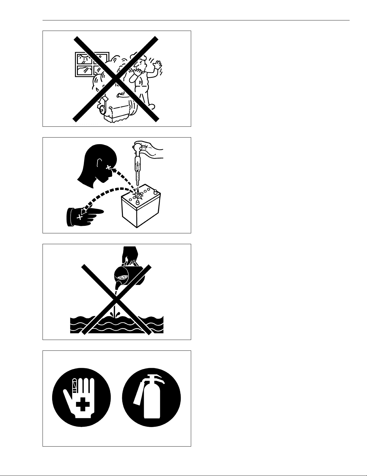
VENTILATE WORK AREA
• If the engine must be running to do some work, make
sure the area is well ventilated. Never run the engine
in a closed area. The exhaust gas contains
poisonous carbon monoxide.
PREVENT ACID BURNS
• Sulfuric acid in battery electr olyte is po isonous. It is
strong enough to burn skin, clothing and cause
blindness if splashed into eyes. Keep electrolyte
away from eyes, hands and clothing. If you spill
electrolyte on yourself, flush with water, and get
medical attention immediately.
DISPOSE OF FLUIDS PROPERLY
• Do not pour fluids into the ground, down a drain, or
into a stream, pond, or lake. Observe relevant
environmental prot ectio n regulati ons whe n disp osing
of oil, fuel, coolant, electrolyte and other harmful
waste.
PREPARE FOR EMERGENCIES
• Keep a first aid kit and fire extingui sher handy at all
times.
• Keep emergency numbers for doctors, ambulance
service, hospital and fire department near your
telephone.
3
ZD21N-EC, ZD21-EC, ZD28-EC, WSM
KiSC issued 09, 2006 A
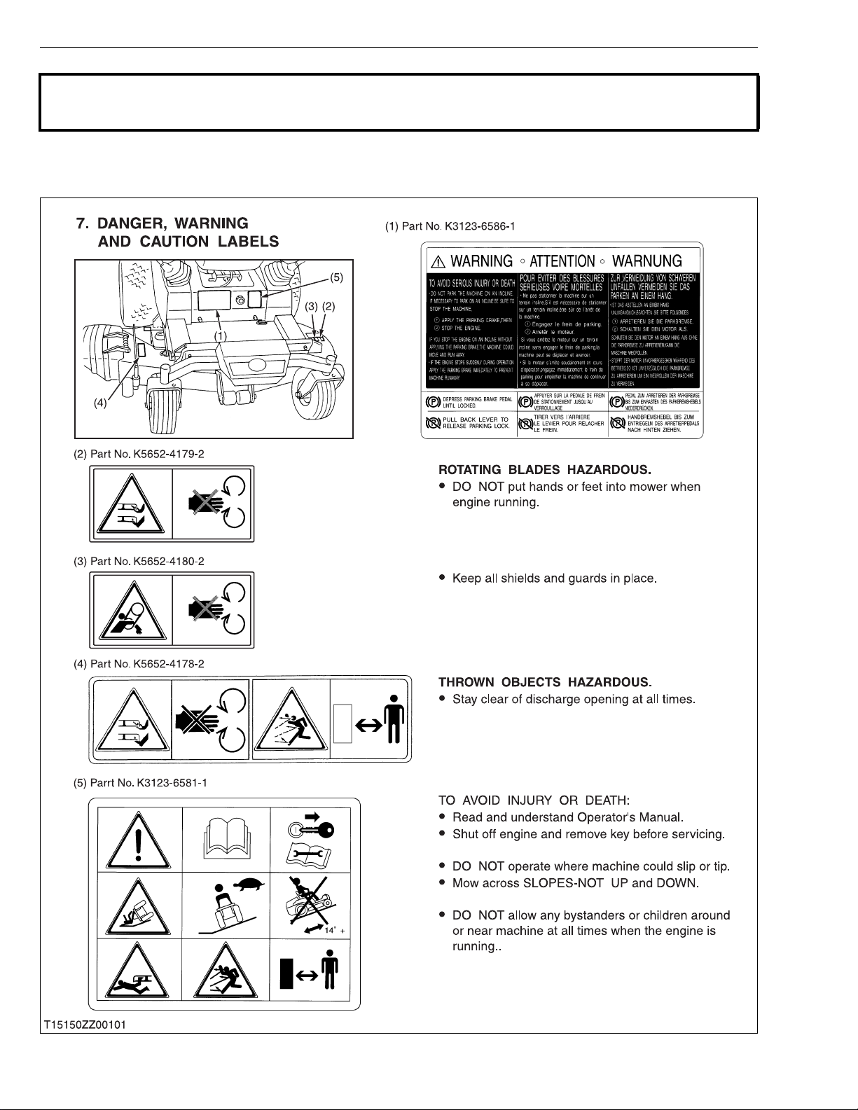
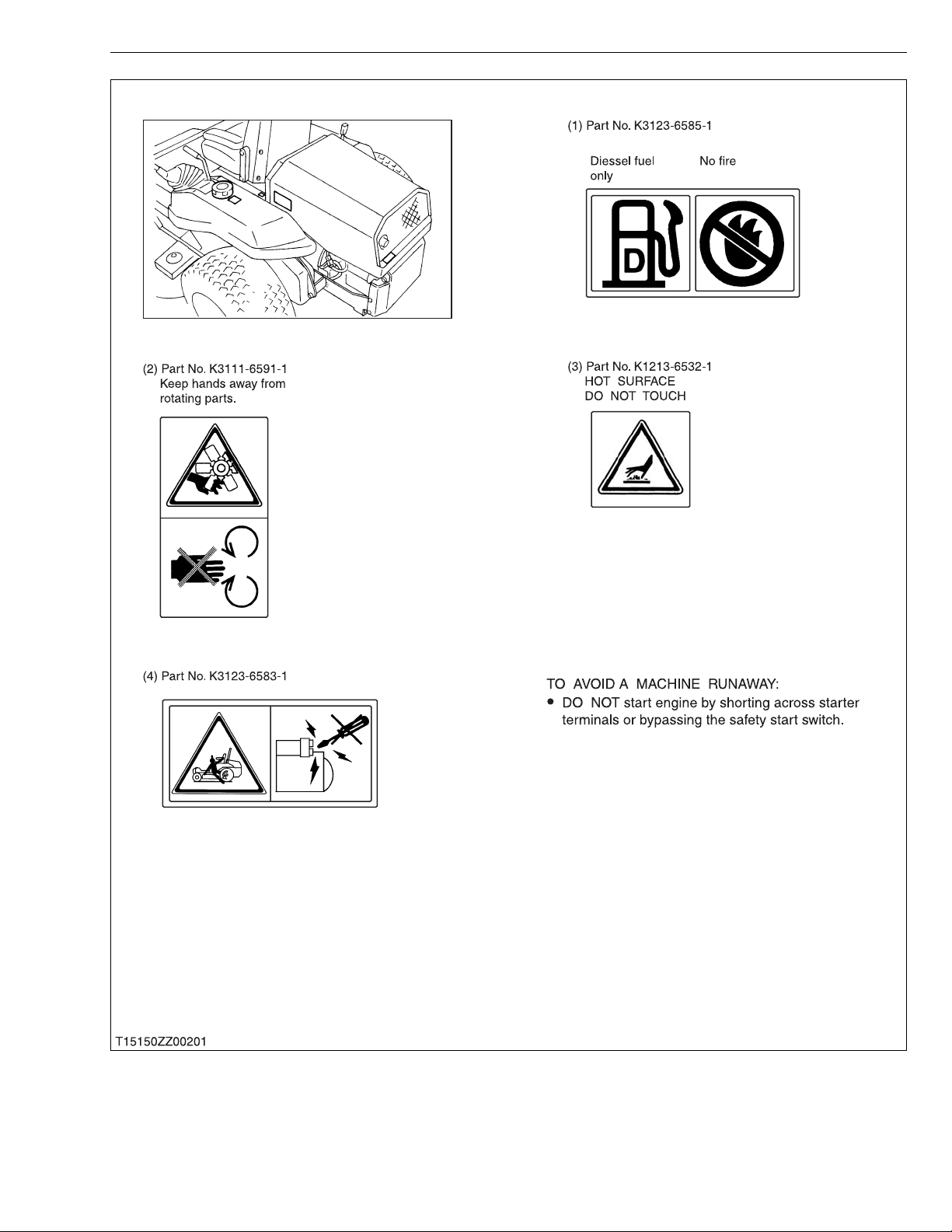
SAFETY INSTRUCTIONS
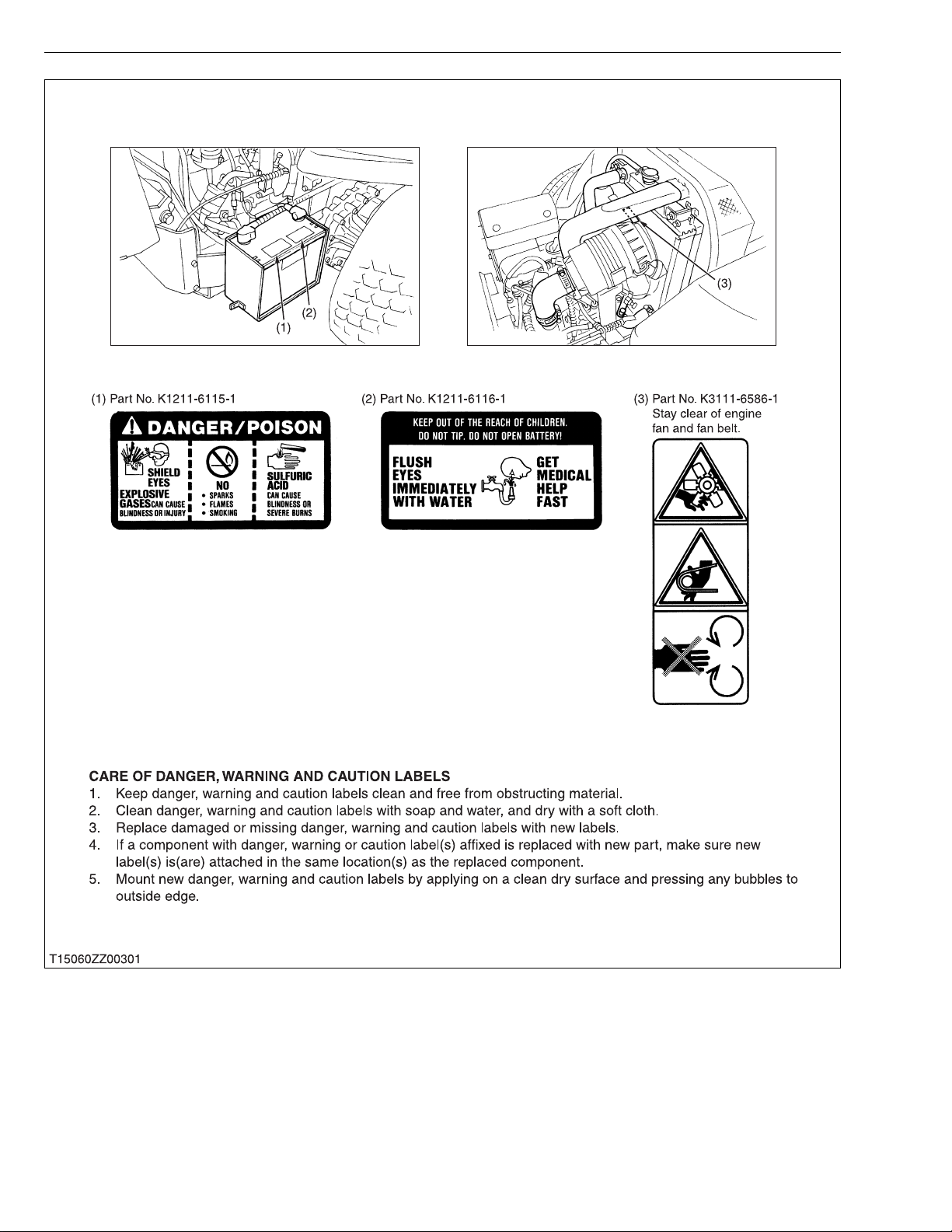
SAFETY DECALS
· The following safety decals are installed on the machine.
If a decal becomes dama ged , il legib le or is no t o n t he ma chin e, repla ce i t. Th e de cal p art nu mb er is list ed
in the parts list.
4
ZD21N-EC, ZD21-EC, ZD28-EC, WSM
KiSC issued 09, 2006 A
SAFETY INSTRUCTIONS
5
ZD21N-EC, ZD21-EC, ZD28-EC, WSM
KiSC issued 09, 2006 A
SAFETY INSTRUCTIONS
6

ZD21N-EC, ZD21-EC, ZD28-EC, WSM
KiSC issued 09, 2006 A
SPECIFICATIONS
Model ZD21N-EC ZD21-EC ZD28-EC
Maximum gross power (SAE) 15.7 kW (21 HP)*
Model D782-E-XFM5 D1105-E2-ZD
Type Indirect injection, vertical, water cooled, 4-cycle diesel engine
Number of cylinders 3
Bore and stroke 67.0 × 73.6 mm (2.64 × 2.90 in.) 78.0 × 78.4 mm
Total displacement 778 cm
Rated revolution 3200 rpm 3000 rpm
Combustion chamber Spherical type (E-TVCS)
Fuel injection pump Bosch MD type mini pump
Governor Centrifugal ball mechanical governor
Engine
Injection nozzle Bosch throttle type
Injection timing 0.33 to 0.37 rad (19° to 21°) before T.D.C.
Injection order 1-2-3
Injection pressure 13.73 MPa (140 kgf/cm
Lubricating system Forced Iubrication by gear pump
Cooling system Pressurized radiator, forced circulation with water pump
Lubricating oil
Starting system Electric starter (12 V, 1.1 kW)
Battery 51 R (12 V, 450 CCA)
Fuel
Fuel tank 30 L (5.8 U.S.gals., 4.8 lmp.gals.)
Engine crankcase 3.5 L (3.7 U.S.qts., 3.1 Imp.qts.)
Engine coolant
Capacities
Recovery tank 0.25 L (0.26 U.S.qts., 0.22 Imp.qts.)
Transmission (Including
HST and cylinder)
Rear axle gear case 1.8 L (1.9 U.S.qts., 1.6 Imp.qts.)*2 each
Mower gear case oil 0.40 L (0.42 U.S.qts., 0.35 Imp.qts.)
Tires
Travelling
speeds
Front 15 × 6.0-6 (4PR) Rib
Rear 23 × 10.5-12 (4PR) Turf 24 × 12.0-12 (4PR) Turf
Forward
Reverse
NOTE: *1 Manufacturer’s estimate
2
Oil amount when the oil level is at the upper level.
*
3
At 3200 engine rpm
*
4
At 3000 engine rpm
*
API Service classification CC or CD, Below 0 °C (32 °F) : SAE 10W or 10W-30, 0 to 25 °C
(32 °F to 77 ° F) : SAE 20 or 10W-30, Above 25 °C (77 °F) : SAE 30 or 10W-30
[No. 1-D diesel fuel, if temperature is below – 10 °C (14 °F)]
2.6 L (2.7 U.S.qts., 2.3 Imp.qts.)
0 to 14.5 km/h
(0 to 9.0 mph)*
0 to 8.0 km/h
(0 to 5.0 mph)*
3
(47.5 cu.in.) 1123 cm3 (68.5 cu.in.)
No. 2-D Diesel fuel (ASTM D975)
4.0 L (4.2 U.S.qts., 3.5 Imp.qts.)*
3
3
1
0 to 15.0 km/h
(0 to 9.3 mph)*
0 to 8.3 km/h
(0 to 5.2 mph)*
2
, 1990 psi)
3
3
SPECIFICATIONS
20.9 kW (28 HP)*
(3.07 × 309 in.)
3.4 L
(3.6 U.S.qts., 3.0 Imp.qts.)
3.8 L
(4.0 U.S.qts., 3.3 Imp.qts.)
2
0 to 15.0 km/h
(0 to 9.3 mph)*
0 to 8.3 km/h
(0 to 5.2 mph)*
1
4
4
W1028929
7

ZD21N-EC, ZD21-EC, ZD28-EC, WSM
KiSC issued 09, 2006 A
Model ZD21N-EC ZD21-EC ZD28-EC
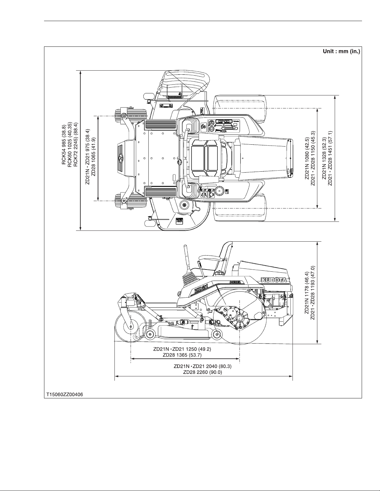
Overall length 2040 mm (80.3 in.) 2260 mm (90.0 in.)
Overall width (Without mower)
Dimensions
Weight (With mower deck)
PTO Shaft drive KUBOTA 10 tooth in spline
PTO clutch Wet multi discs
Revolution (PTO speed)
PTO brake Wet single disc
Steering 2-Hand levers
Transmission 2-Hydrostatic transmission with gear
Brake Internal expanding shoe / Hand
The company reserves the right to change the specifications without notice.
Overall height
Wheel base 1250 mm (49.2 in.) 1365 mm (53.7 in.)
Treads
Front 975 mm (38.4 in.) 1065 mm (41.9 in.)
Rear 1080 mm (42.5 in.) 1150 mm (45.3 in.)
1328 mm (52.3 in.) 1451 mm (57.1 in.)
1178 mm (46.4 in.) 1193 mm (47.0 in.)
570 kg (1256.6 lbs) / With
560 kg (1234.8 lbs) / With
54" mower deck
1 speed (2530 rpm at 3200 engine rpm)
60" mower deck
SPECIFICATIONS
652 kg (1437.7 lbs) / With
60" mower deck
676 kg (1490.6 lbs) / With
72” mower deck
1 speed (2540 rpm at 3000
engine rpm)
W1031261
Model RCK54-21NZ-EC RCK54-21NZ-EC RCK60-28Z-EC RCK72-28Z-EC
Suitable machine ZD21N-EC ZD21N-EC ZD28-EC
Mounting method Quick joint, parallel linkage
Adjustment of cutting height Dial gauge
Cutting width 1372 mm (54.0 in.) 1524 mm (60.0 in.) 1829 mm (72.0 in.)
Cutting height 25 to 127 mm (1.0 to 5.0 in.)
Weight (Approx.) 103 kg (227 lbs) 120 kg (265 lbs) 150 kg (331 lbs)
Blade spindle speed 50.1 r/s (3006 rpm) 44.6 r/s (2676 rpm) 44.8 r/s (2688 rpm) 40.0 r/s (2400 rpm)
Mower
The company reserves the right to change the specifications without notice.
Blade tip velocity 74.7 m/s
(14701 fpm)
Blade length 475 mm (18.7 in.) 523 mm (20.6 in.) 625 mm (24.6 in.)
Number of blades 3
Total length 985 mm (38.8 in.) 1025 mm (40.4 in.) 1095 mm (43.1 in.)
Dimensions
Discharge Right side
Total width 1690 mm (60.5 in.) 1845 mm (72.6 in.) 2245 mm (88.4 in.)
Total height 300 mm (11.8 in.)
73.4 m/s
(14445 fpm)
73.6 m/s
(14484 fpm)
78.5 m/s
(15449 fpm)
W1029898
8
ZD21N-EC, ZD21-EC, ZD28-EC, WSM
KiSC issued 09, 2006 A
DIMENSIONS
DIMENSIONS
9

G GENERAL
KiSC issued 09, 2006 A

GENERAL
KiSC issued 09, 2006 A
CONTENTS
1. IDENTIFICATION............................................................................................. G-1
2. GENERAL PRECAUTIONS ............................................................................ G-2
3. HANDLING PRECAUTIONS FOR ELECTRICAL PARTS AND WIRING..G-3
[1] WIRING...................................................................................................... G-3
[2] BATTERY................................................................................................... G-5
[3] FUSE.......................................................................................................... G-5
[4] CONNECTOR............................................................................................ G-5
[5] HANDLING OF CIRCUIT TESTER......................................................... G-6
4. LUBRICANTS, FUEL AND COOLANT ......................................................... G-7
5. TIGHTENING TORQUES ............................. ....... ...... ....... ...... ....... ...... ....... .... G- 9
[1] GENERAL USE SCREWS, BOLTS AND NUTS................................... G-9
[2] STUD BOLTS............................................................................................ G-9
[3] METRIC SCREWS, BOLTS AND NUTS ............................................. G-10
[4] AMERICAN STANDARD SCREWS, BOLTS AND NUTS WITH UNC
OR UNF THREADS ............................................................................... G-10
[5] PLUGS..................................................................................................... G-10
6. MAINTENANCE CHECK LIST..................................................................... G-11
7. CHECK AND MAINTENANCE......... ...... ...... ....................................... ....... .. G-13
[1] DAILY CHECK........................................................................................ G-13
[2] CHECK POINTS OF INITIAL 50 HOURS........................................... G-17
[3] CHECK POINT OF INITIAL 100 HOURS ........................................... G-19
[4] CHECKING POINTS OF INITIAL 200 HOURS................................... G-20
[5] CHECK POINTS OF EVERY 50 HOURS........................................... G-22
[6] CHECK POINTS OF EVERY 100 HOURS......................................... G-26
[7] CHECK POINTS OF EVERY 150 HOURS......................................... G-31
[8] CHECK POINTS OF EVERY 200 HOURS......................................... G-31
[9] CHECK POINTS OF EVERY 400 HOURS......................................... G-33
[10]CHECK POINTS OF EVERY 1 YEAR................................................ G-33
[11]CHECK POINT OF EVERY 2 YEARS ................................................ G-36
[12]OTHERS .................................................................................................. G-37
8. SPECIAL TOOLS.......................................................................................... G-39
[1] SPECIAL TOOLS FOR ENGINE .......................................................... G-39
[2] SPECIAL TOOLS FOR MACHINE........................................................ G-45
ZD21N-EC, ZD21-EC, ZD28-EC, WSM
KiSC issued 09, 2006 A
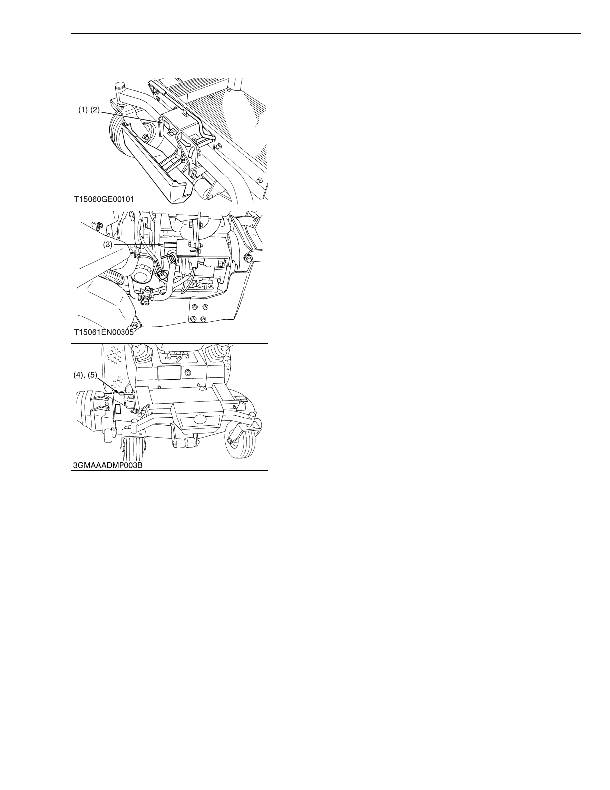
1. IDENTIFICATION
G GENERAL
When contacting your loca l KUBOTA distr ibutor, alway s specify
engine serial num ber (3), machine serial number (2 ), mower serial
number (4) and hour meter reading.
(1) Machine Identification Plate
(2) Machine Serial Number
(3) Engine Serial Number
(4) Mower Serial Number
(5) Mower Identification Plate
W1010714
G-1
ZD21N-EC, ZD21-EC, ZD28-EC, WSM
KiSC issued 09, 2006 A
2. GENERAL PRECAUTIONS
• During disa ssembly, ca refully ar range removed parts in a cle an
area to prevent confusion later. Screws, bolts and nuts should be
installed in their original position to prevent reassembly errors.
• When special tools are requi red, use KUBOT A genuine speci al
tools. Special tools which are not frequently used should be
made according to the drawings provided.
• Before disassembling or servicing electrical wires, always
disconnect the ground cable from the battery first.
• Remove oil and dirt from parts before measuring.
• Use only KUBOTA genuine parts for parts replacement to
maintain machine performance and to assure safety.
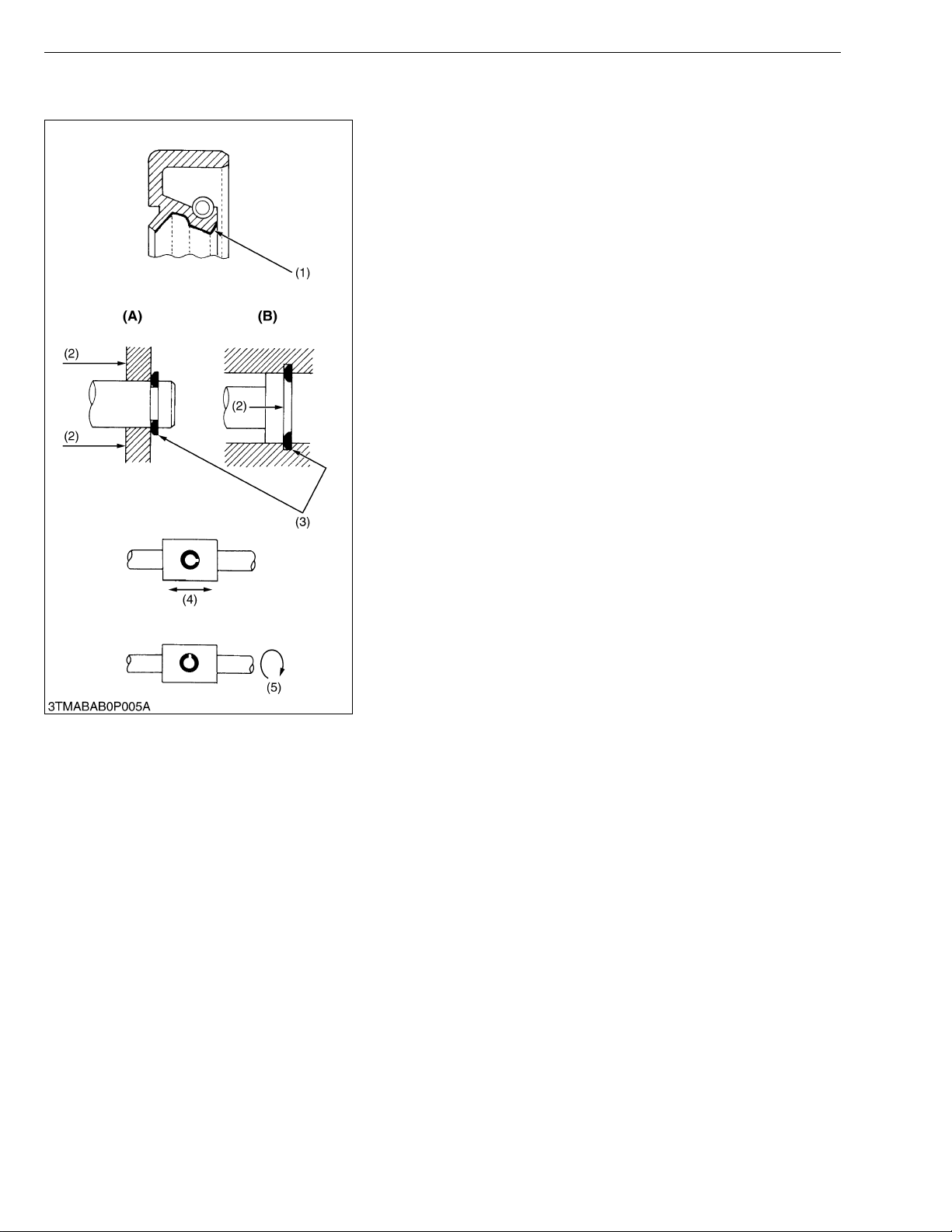
• Gaskets and O-rings must be replaced during reassembly.
Apply grease to new O-rings or oil seals before assembling.
See the figure left side.
• When reassem bling external snap rings or inte rnal snap rings,
they must be positioned so that sharp edge faces against the
direction from which a force is applied. See the figure left side.
• When insert ing spring pins, their splits must face the direction
from which a force is applied. See the figure left side.
• To prevent dam age to the hydraulic s ystem, use only sp ecified
fluid or equivalent.
(1) Grease
(2) Force
(3) Sharp Edge
(4) Axial Force
(5) Rotating Movement
G GENERAL
(A) External Snap Ring
(B) Internal Snap Ring
W1010904
G-2
ZD21N-EC, ZD21-EC, ZD28-EC, WSM
IMPORTANT■
KiSC issued 09, 2006 A
G GENERAL
3. HANDLING PRECAUTIONS FOR ELECTRICAL PARTS
AND WIRING
To ensure safety and prevent damage to the machine and
surrounding equipm ent, heed the following pr ecautions in handling
electrical parts and wiring.
• Check electrical wiring for damage and loosened
connection every year. To this end, educate the customer to
do his or her own check and at the s ame time recommend
the dealer to perform periodic check for a fee.
• Do not attempt to modify or remodel any electrical parts and
wiring.
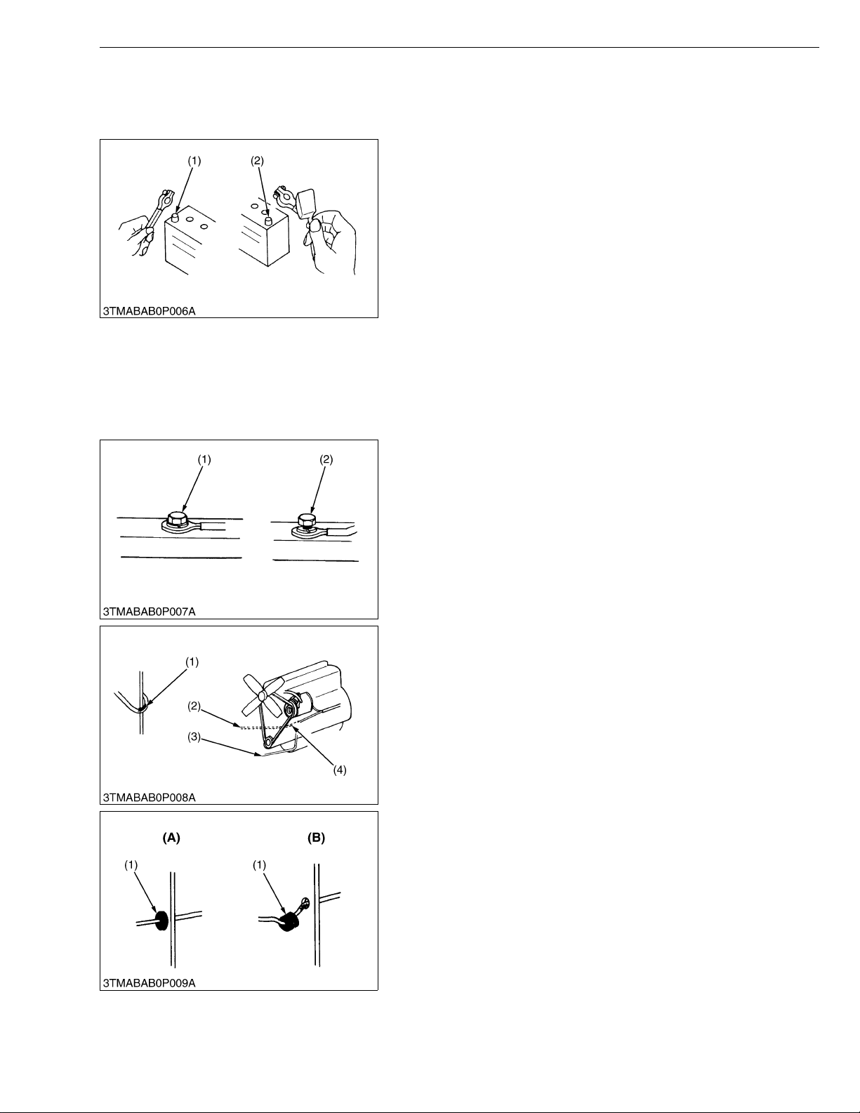
• When removing th e ba tter y cab le s, dis co nn ect t he n egat ive
cable first. When in stalling the b attery cables, c onnect the
positive cable first.
(1) Negative Terminal (2) Positive Terminal
W1011114
[1] WIRING
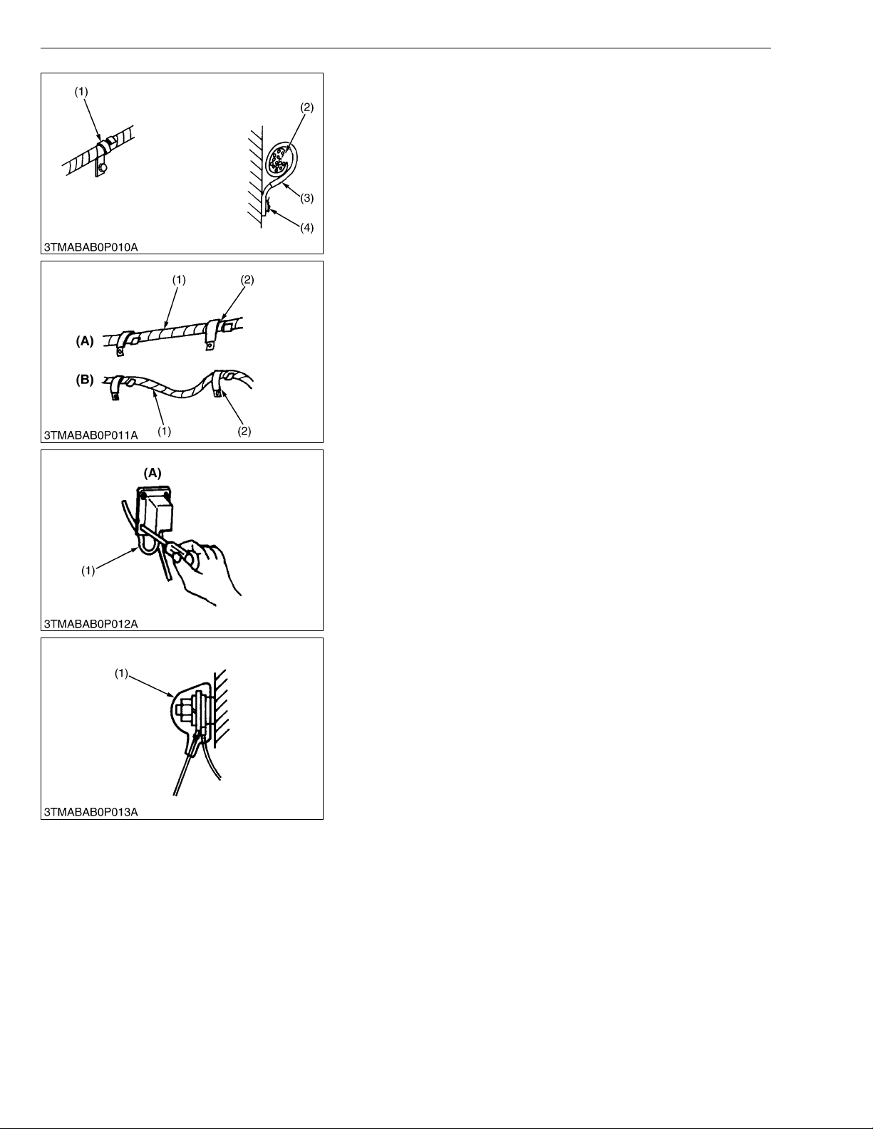
• Securely t ighten wiring terminals.
(1) Correct
(Securely tighten)
(2) Incorrect
(Loosening leads to faulty contact)
W1011216
• Do not let wiring contact dangerous part.
(1) Wiring (Correct)
(2) Wiring (Incorrect)
(3) Dangerous Part
(4) Dangerous Part
• Securely insert grommet.
(1) Grommet (A) Co rrect
(B) Incorrect
W1011313
W1011388
G-3
ZD21N-EC, ZD21-EC, ZD28-EC, WSM
KiSC issued 09, 2006 A
G GENERAL
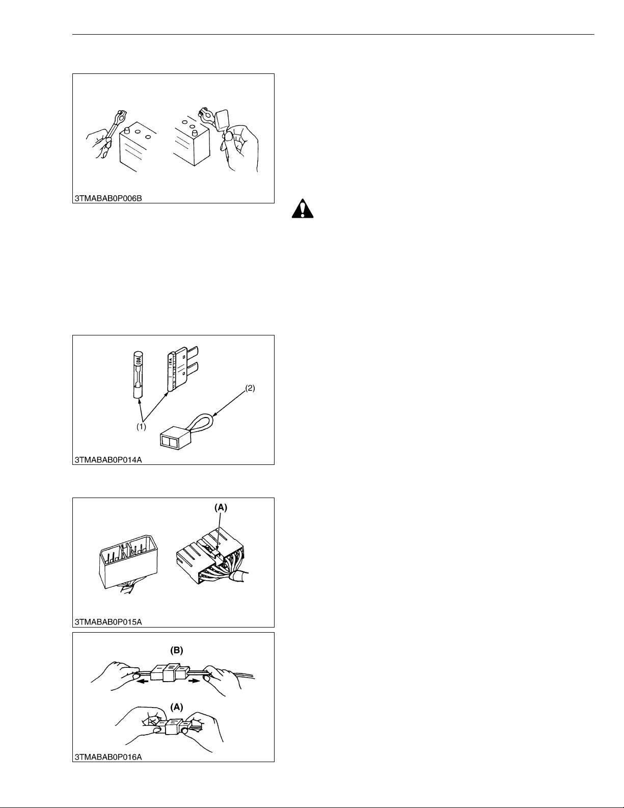
• Securely clamp, being careful not to damage wiring.
(1) Clamp
• Wind Clamp Spirally
(2) Wire Harness
(3) Clamp
(4) Welding Dent
W1011458
• Clamp wiring so that there is no twist, unnecessary sag, or
excessive tension, except for movable part, where sag be
required.
(1) Wiring
(2) Clamp
(A) Correct
(B) Incorrect
W1011587
• In installing a part, take care not to get wiring caught by it.
(1) Wiring (A) Incorrect
W1011670
• After installing wiring, check protection of terminals and clamped
condition of wiring, only connect battery.
(1) Cover
• Securely Install Cover
W1011735
G-4
ZD21N-EC, ZD21-EC, ZD28-EC, WSM
KiSC issued 09, 2006 A
[2] BATTERY
[3] FUSE
G GENERAL
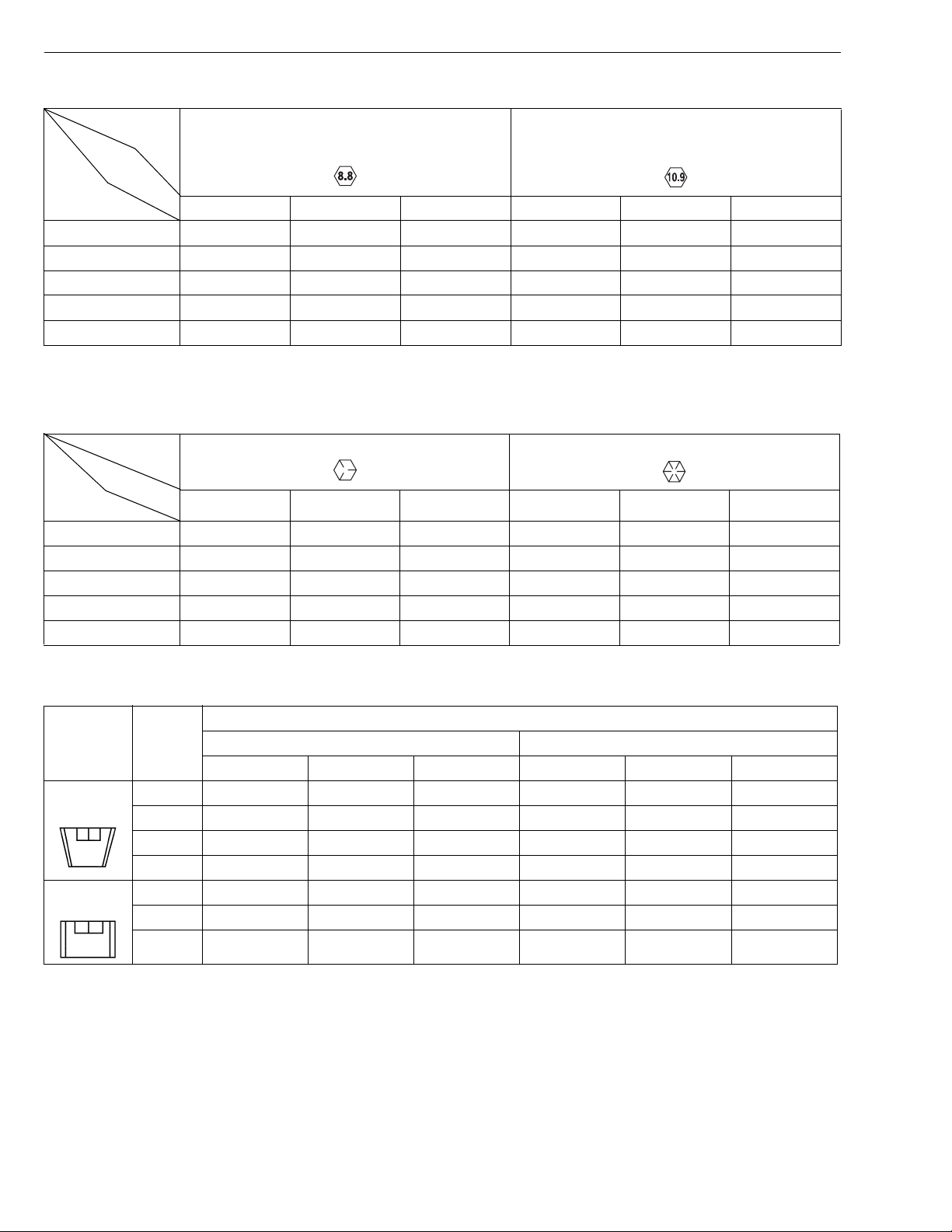
• Take care not to confuse positive and negative terminal posts.
• When removing b attery cables, disconnect negative cable first.
When installing battery cables, check for polarity and connect
positive cable first.
• Do not install a ny battery with capacity other than is specified
(Ah).
• After connecting cables to battery terminal posts, apply high
temperature grease to them a nd sec urely in stall t erminal covers
on them.
• Do not allow dirt and dust to collect on battery.
CAUTION
• Take care not to let battery liquid spill on your skin and
clothes. If contaminated, wash it off with water immediately.
• Before recharging the battery, remove it from the machine.
• Before recharging, remove cell caps.
• Do recharging in a well- ventilated place where there is no
open flame nearby, as hydrogen gas and oxygen are formed.
W1011816
[4] CONNECTOR
• Use fuses with specified capacity.
Neither too large or small capacity fuse is acceptable.
• Never use steel or copper wire in place of fuse.
• Do not install working light, radio set, etc. on machine which is not
provided with reserve power supply.
• Do not install accessories if fuse capacity of reserve power
supply is exceeded.
(1) Fuse (2) Slow Blow Fuse
W1012092
• For connector with lock, push lock to separate.
(A) Push
W1012211
• In separating connectors, do not pull wire harnesses.
• Hold connector bodies to separate.
(A) Correct (B) Incorrect
W1012272
G-5

ZD21N-EC, ZD21-EC, ZD28-EC, WSM
KiSC issued 09, 2006 A
G GENERAL
• Use sandpaper to remove rust from terminals.
• Repair deformed terminal. Make certain there is no terminal
being exposed or displaced.
(1) Exposed Terminal
(2) Bend Terminal
(3) Sandpaper
(4) Rust
W1012346
• Make certain that there is no female connector being too open.
(A) Correct (B) Incorrect
W1012430
[5] HANDLING OF CIRCUIT TESTER
• Use tester correctly following manual provided with tester.
• Check for polarity and range .
W1012684
G-6

ZD21N-EC, ZD21-EC, ZD28-EC, WSM
KiSC issued 09, 2006 A
4. LUBRICANTS, FUEL AND COOLANT
G GENERAL
No. Place
1Fuel
Cooling
system
2Coolant
Recovery
tank
3 Engine crankcase
4 T ransmission case
Transmission case with
5
filter & hose
6 Rear axle case
7 Mower gear case
* Oil amount when the oil level is the upper of the oil level gauge.
** KUBOTA original transmission hydraulic fluid
ZD21N-EC ZD21-EC ZD28-EC
2.7 U.S.qts.
2.3 Imp.qts.
3.7 U.S.qts.
3.1 Imp.qts.
Capacity
30 L
7.9 U.S.gals.
6.6 Imp.gals.
2.6 L
4.0 U.S.qts.
3.3 Imp.qts.
0.25 L
0.26 U.S.qts.
0.22 Imp.qts.
3.5 L*
3.6 U.S.qts.
3.0 Imp.qts.
3.2 L
3.4 U.S.qts.
2.8 Imp.qts.
4.0 L
4.2 U.S.qts.
3.5 Imp.qts.
1.8 L each
1.9 U.S.qts. each
1.6 Imp.qts. each
0.40 L
0.42 U.S.qts.
0.35 Imp.qts.
3.8 L
3.4 L*
Lubricants, fuel and coolant
No. 2-D diesel fuel
No. 1-D diesel fuel if temperature is
below – 10 °C (14 °F)
Fresh clean water (soft water) with
anti-freeze
Engine oil : API Service
Classification CC or CD
Below 0 °C (32 °F) : SAE10W,
10W-30 or 10W-40
0 to 25 °C (32 to 77 °F): SAE20,
10W-30 or 10W-40
Above 25 °C (77 °F): SAE30, 10W30 or 10W-40
KUBOTA UDT or SUPER UDT
fluid**
G-7

ZD21N-EC, ZD21-EC, ZD28-EC, WSM
KiSC issued 09, 2006 A
G GENERAL
Greasing, oiling (Machine)
No. Place No. of greasing point Capacity Type of grease
7 Speed control lever boss 2
8 Speed control lever 2
9 Center pin 1
10 King pin 2
Until grease overflows
11 Front wheel 2
SAE multi-purpose
type grease
12 Front lift arm 2
13 Universal joint 3
14 Seat adjuster 2
15 Throttle cable 2 Moderate amount Engine oil
Greasing (Mower)
16 Universal joint 3
17 Three spindle shafts 3
Until grease overflows
18 Belt tension pulley 1
SAE multi-purpose
type grease
19 Belt tension pivot 1
G-8

ZD21N-EC, ZD21-EC, ZD28-EC, WSM
KiSC issued 09, 2006 A
G GENERAL
5. TIGHTENING TORQUES
[1] GENERAL USE SCREWS, BOLTS AND NUTS
Screws, bolts and nu ts whose tightening torques are not speci fied in t his Worksh op Manual should b e tightened
according to the table below.
Indication on top of
bolt
Material of bolt SS400, S20C S43C, S48C
Material of opponent
part
Unit
Diameter
M6
(6 mm, 0.24 in.)
M8
(8 mm, 0.31 in.)
M10
(10 mm, 0.39 in.)
M12
(12 mm, 0.47 in.)
M14
(14 mm, 0.55 in.)
M16
(16 mm, 0.63 in.)
M18
(18 mm, 0.71 in.)
M20
(20 mm, 0.79 in.)
No-grade or 4T 7T 9T
SCr435,
SCM435
Ordinariness Aluminum Ordinariness Aluminum Ordinariness
N·m kgf·m ft-lbs N·m kgf·m ft-lbs N·m kgf·m ft-lbs N·m kgf·m ft-lbs N·m kgf·m ft-lbs
7.85
0.80
5.79
7.85
0.80
5.79
9.81
1.00
7.24
7.85
0.80
5.79
12.3
to
9.31
17.7
to
20.5
39.3
to
45.1
62.8
to
72.5
108
to
125
167
to
191
246
to
284
334
to
392
to
0.95
1.8
to
2.1
4.0
to
4.6
6.4
to
7.4
11.0
to
12.8
17.0
to
19.5
25.0
to
29.0
34.0
to
40.0
to
6.87
13.1
to
15.1
29.0
to
33.2
46.3
to
53.5
79.6
to
92.5
123
to
141
181
to
209
246
to
289
to
to
to
8.82
0.90
6.50
16.7
19.6
31.4
34.3
1.7
12.3
to
to
2.0
3.2
to
3.5
–––
–––
–––
–––
–––
to
14.4
23.2
to
to
25.3
to
11.2
23.6
to
27.4
48.1
to
55.8
77.5
to
90.2
124
to
147
197
to
225
275
to
318
368
to
431
to
1.15
2.4
to
2.8
4.9
to
5.7
7.9
to
9.2
12.6
to
15.0
20.0
to
23.0
28.0
to
32.5
37.5
to
44.0
to
8.31
17.4
to
20.2
35.5
to
41.2
57.2
to
66.5
91.2
to
108
145
to
166
203
to
235
272
to
318
to
to
to
8.82
0.90
6.50
17.7
20.5
39.3
44.1
62.8
72.5
1.8
13.1
to
to
2.1
4.0
to
4.5
6.4
to
7.4
–––
–––
–––
–––
to
15.1
29.0
to
to
32.5
46.3
to
to
53.5
to
14.2
29.5
to
34.3
60.9
to
70.6
103
to
117
167
to
196
260
to
304
344
to
402
491
to
568
1.25
to
1.45
3.0
to
3.5
6.2
to
7.2
10.5
to
12.0
17.0
to
20.0
26.5
to
31.0
35.0
to
41.0
50.0
to
58.0
W1034542
9.05
to
10.4
21.7
to
25.3
44.9
to
52.0
76.0
to
86.7
123
to
144
192
to
224
254
to
296
362
to
419
[2] STUD BOLTS
Material of opponent
part
Unit
Diameter
M8
(8 mm, 0.31 in.)
M10
(10 mm, 0.39 in.)
M12
(12 mm, 0.47 in.)
Ordinariness Aluminum
N·m kgf·m ft-lbs N·m kgf·m ft-lbs
11.8
to
15.6
24.6
to
31.3
29.5
to
49.0
1.2
to
1.6
2.5
to
3.2
3.0
to
5.0
8.68
8.82
to
11.5
18.1
23.1
21.7
36.1
to
11.8
19.7
to
to
25.4
to
31.4 3.2 23.1
0.90
to
1.2
2.0
to
2.6
6.51
to
8.67
14.5
to
18.8
W10481390
G-9
ZD21N-EC, ZD21-EC, ZD28-EC, WSM
KiSC issued 09, 2006 A
[3] METRIC SCREWS, BOLTS AND NUTS
G GENERAL
Grade
Unit
Nominal
Diameter
M8 23.6 to 27.4 2.4 to 2.8 17.4 to 20.2 29.4 to 34.3 3.0 to 3.5 21.7 to 25.3
M10 48.1 to 55.8 4.9 to 5.7 35.5 to 41.2 60.8 to 70.5 6.2 to 7.2 44.9 to 52.1
M12 77.5 to 90.1 7.9 to 9.2 57.2 to 66.5 103.0 to 117.0 10.5 to 12.0 76.0 to 86.8
M14 124.0 to 147.0 12.6 to 15.0 91.2 to 108.0 167.0 to 196.0 17.0 to 20.0 123.0 to 144.0
M16 196.0 to 225.0 20.0 to 23.0 145.0 to 166.0 260.0 to 303.0 26.5 to 31.0 192.0 to 224.0
N·m kgf·m ft-lbs N·m kgf·m ft-lbs
Property class 8.8 Property class 10.9
0000001413E
[4] AMERICAN STANDARD SCREWS, BOLTS AND NUTS WITH UNC OR
UNF THREADS
Grade
Unit
Nominal
Diameter
5/16 23.1 to 27.8 2.35 to 2.84 17.0 to 20.5 32.5 to 39.3 3.31 to 4.01 24.0 to 29.0
3/8 47.5 to 57.0 4.84 to 5.82 35.0 to 42.0 61.0 to 73.2 6.22 to 7.47 45.0 to 54.0
1/2 108.5 to 130.2 11.07 to 13.29 80 .0 to 96.0 149 .2 to 179.0 15.22 to 18.27 110.0 to 132.0
9/16 149.2 to 179.0 15 .22 to 18.27 110.0 to 132.0 217.0 to 260.4 22.14 to 26.57 160.0 to 192.0
5/8 203.4 to 244.1 20.75 to 24.91 150.0 to 180.0 298.3 to 358.0 30.44 to 36.53 220.0 to 264.0
N·m kgf·m ft-lbs N·m kgf·m ft-lbs
SAE GR.5 SAE GR.8
0000001414E
[5] PLUGS
Shape Size
Tapered
screw
Straight
screw
Material of opponent part
Ordinariness Aluminum
N·m kgf·m ft-lbs N·m kgf·m ft-lbs
R1/8 12.7 to 21.6 1.3 to 2.2 9.4 to 15.9 12.7 to 19.6 1.3 to 2.0 9.4 to 15.4
R1/4 24.5 to 44.1 2.5 to 4.5 18.1 to 32.5 24.5 to 34.3 2.5 to 3.5 18.1 to 25.4
R3/8 49.0 to 88.3 5.0 to 9.0 36.2 to 65.1 49.0 to 58.8 5.0 to 6.0 36.2 to 43.4
R1/2 58.8 to 107.9 6.0 to 11.0 43.4 to 79.6 58.8 to 78.5 6.0 to 8.0 43.4 to 57.4
G1/4 24.5 to 34.3 2.5 to 3.5 18.1 to 25.3 – – –
G3/8 61.8 to 82.4 6.3 to 8.4 45.6 to 60.8 – – –
G1/2 49.0 to 88.3 5.0 to 9.0 36.2 to 65.1 – – –
0000001666E
G-10

ZD21N-EC, ZD21-EC, ZD28-EC, WSM
IMPORTANT■
KiSC issued 09, 2006 A
6. MAINTENANCE CHECK LIST
G GENERAL
Period
No.
Items
1 Engine oil Change ★✩✩✩✩✩✩
2 Engine oil filter Replace ★✩✩✩
Transmission
3
fluid
Transmission oil
4
filter
Transmission
5
strainer
Rear axle gear
6
case (RH & LH)
fluid
7 Front axle pivot Adjust ★✩✩✩
8 Safety device Check ✩✩✩✩✩✩✩✩✩✩✩✩
Greasing
9
(without mower)
Mower gear box
10
oil
Air cleaner
11
element
12 Battery condition Check ✩✩✩✩✩✩
13 Fan belt Adjust ✩✩✩✩✩✩
14 Parking brake Adjust ✩✩✩✩✩✩
Fuel filter
15
element
16 Fuel line
Change ★✩✩
Replace ★✩✩✩
Clean ★✩✩
Change ★✩✩
Check ✩✩✩✩✩✩✩✩✩✩✩✩
Change ✩✩✩✩
Clean ✩✩✩✩✩✩✩✩✩✩✩✩
Replace
Check ✩✩✩✩✩✩
Replace ✩
Check ✩✩✩✩✩✩
Replace
50 100 150 200 250 300 350 400 450 500 550 600
– ✩✩✩✩✩✩✩✩✩✩✩✩
Service interval
After
since
every
100 hr
every
200 hr
every
200 hr
every
200 hr
every
200 hr
every
200 hr
every
200 hr
every
50 hr
every
50 hr
every
150 hr
every
150 hr
every
50 hr
every
1 year
every
100 hr
every
100 hr
every
100 hr
every
100 hr
every
400 hr
every
100 hr
every
2 years
*1 G-26
Reference
page
G-17
G-18
G-21
G-18
G-20
G-21
G-19
G-22
G-24
G-26
–
–
G-26
G-28
G-29
G-28
G-33
G-28
–
W1037757
• The jobs indicated by ★ must be done initially.
1
*
Suggested cleaning interval is every 100 hours in normal conditions.
This maintenance should be done daily more often in dusty condition than in normal conditions.
G-11

ZD21N-EC, ZD21-EC, ZD28-EC, WSM
KiSC issued 09, 2006 A
G GENERAL
Period
No.
Items
Radiator hose
17
and clamp
18 Hydraulic hose
19 Intake air line
Motion control
20
lever pivot
21 Radiator Clean
22 Coolant Change
Mower gear box
23
oil seal
24 Fuel system Bleed
25 Fuse Replac e G-37
26 Blade Replace G-38
27 Mower belt Replace G-38
Check ✩✩✩
Replace
Check ✩✩✩
Replace
Check ✩✩✩
Replace
Adjust ✩✩✩
Replace
50 100 150 200 250 300 350 400 450 500 550 600
Service interval
After
since
every
200 hr
every
2 years
every
200 hr
every
2 years
every
200 hr
every
2 years
every
200 hr
every
1 year
every
1 year
every
2 years
Service
as
required
Reference
page
G-31
G-31
G-32
*2
G-32
G-34
G-34
G-36
G-38
W1063926
–
–
–
■ IMPORTANT
2
Replace if necessary.
*
G-12

ZD21N-EC, ZD21-EC, ZD28-EC, WSM
KiSC issued 09, 2006 A
G GENERAL
7. CHECK AND MAINTENANCE
CAUTION
• Be sure to check and service the machine o n a flat place with en gine shut off, the pa rking brake on and
chock the wheels.
[1] DAILY CHECK
To prevent trouble from occurring, it is important to know the condition of the machine. Check the following items
before starting.
Checking
• Check areas where previous trouble was experienced.
• Walk around the machine.
1. Tire pressure, wear and damage
2. Oil and water leak
3. Engine oil level
4. Transmission fluid le vel
5. Coolant level in the recovery tank
6. Damage of machine body, tightness of all bolts and nuts
7. Radiator screen
8. Panel screen
9. Brake play
10.Air cleaner
11.Fuel level
12.Oiling
•Mower
1. Oil leak
2. Make sure blade cap screws are tight.
3. Check blades for wear or damage.
4. Check all hardwar e.
5. Make sure all pins are in place.
6. Mower deck cleaning
7. Greasing
• While sitting in the operator’s seat,
1. Motion contr ol lever
2. Parking brake
• Turning the key switch “ON”
1. Performance of the easy checker light
• Starting the engine,
1. Color of the exhaust fumes
2. Safety start switch, seat safety control and another safety control and another safety devices.
3. Check for abnorma l nois e and vi br ati on.
G-13
ZD21N-EC, ZD21-EC, ZD28-EC, WSM
■
IMPORTANT■
KiSC issued 09, 2006 A
G GENERAL
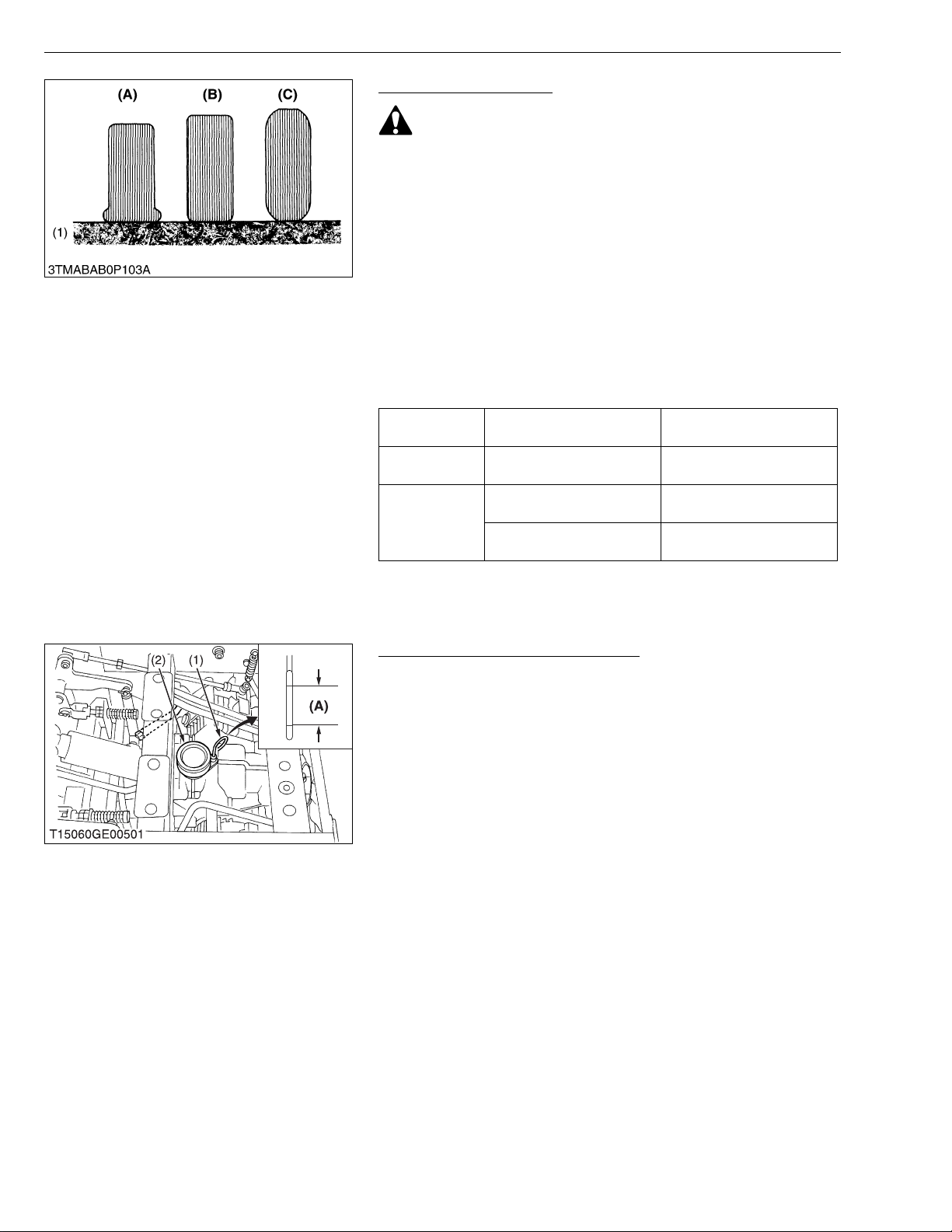
Checking Tire Pressure
WARNING
To avoid personal injury:
• Do not attempt to mount a tire on a rim. This should be done
by a qualified person with the proper equipment.
• Always maintain the correct tire pressure.
Inflation pressure in front tires rises quickly when using
compressed air.
Do not inflate tires above the r ecommended pressure shown
in the Operator’s Manual.
IMPORTANT
• Do not use tires larger than specified.
■ Inflation Pressure
Though the inflation pressure is factory-set to the prescribed
level, it naturally drops slowly in the cours e of time. Thus, check it
and inflate as necessary.
Tire Sizes
Front 15 × 6.0-6, 4PR Rib
23 × 10.5-12, 4PR Turf
Rear
24 × 12.0-12, 4PR Turf
Recommended Inflation
Pressure
207 kPa
2
140 kPa
2
140 kPa
2
, 30 psi)
, 20 psi)
, 20 psi)
(2.1 kgf/cm
(1.4 kgf/cm
(1.4 kgf/cm
(1) Ground (A) Insufficient
(B) Normal
(C) Excessive
W1041550
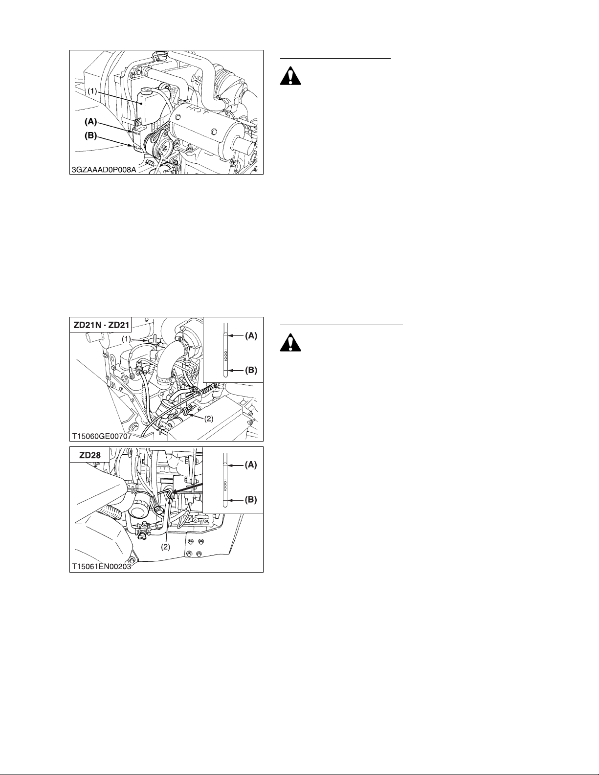
Checking Transmission Fluid Level
1. Park the mach ine on a flat surface, lower the imp lement to the
ground and shut off engine and remove the key.
2. Raise and lock the operator’s seat.
3. To check the oil level, draw out the dipstick, wipe it clean, replace
it, and draw it out again. Check to see that the oil level lies
between the two not ches. If the level is to o low, add ne w oil to
the prescribed level at the oil inlet.
(See page G-7.)
• If oil level is low, do not run engine.
(1) Oil Level Dipstick
(2) Oil Plug and Breather Cup
(A) Oil level is acceptable within this
range.
W1041984
G-14
ZD21N-EC, ZD21-EC, ZD28-EC, WSM
■
KiSC issued 09, 2006 A
G GENERAL
Checking Coolant Level
CAUTION
To avoid personal injury:
• Do not remove the radiator cap when the engine is hot. Then
loosen cap slightly to the stop to relieve any excess
pressure before removing cap completely.
1. Check to see t hat the coola nt level is b etween the “FULL” and
“LOW” marks of recovery tank.
2. When the coolant level drops due to evaporation, add water only
up to the full level of the recovery tank.
In case of leaka ge, add anti-freeze and water in the specified
mixing ratio up to the full level.
(See page G-7.)
IMPORTANT
• If the radiator cap has to be removed, follow the caution
above and securely retighten the cap.
• Use clean, distilled water a nd anti-freeze t o fill the r ecovery
tank.
(1) Recovery Tank (A) FULL
(B) LOW
W1042377
Checking Engine Oil Level
CAUTION
To avoid personal injury:
• Always stop the engine and remove the key before checking
oil.
1. Check engine oil before starti ng and 5 minut es or more afte r the
engine has stopped.
2. Wipe dipstick area clean.
3. To check the oil level, remove the dipstick, wipe it clean, replace
it, and draw it out again. Check to see that the oil level is between
the two notches.
4. Add new oil to the prescribed level at the oil port if necessary.
5. When using a different brand or viscosity oil from the previous
one, remove all of the old oil and oil filter. Never mix two different
types of oil.
6. Use the proper Engine Oil SAE according to the ambient
temperatures. (See page G-7.)
(1) Engine Oil Port
(2) Oil Level Dipstick
(A) Upper Level
(B) Lower Level
W1042659
G-15
ZD21N-EC, ZD21-EC, ZD28-EC, WSM
■
KiSC issued 09, 2006 A
G GENERAL
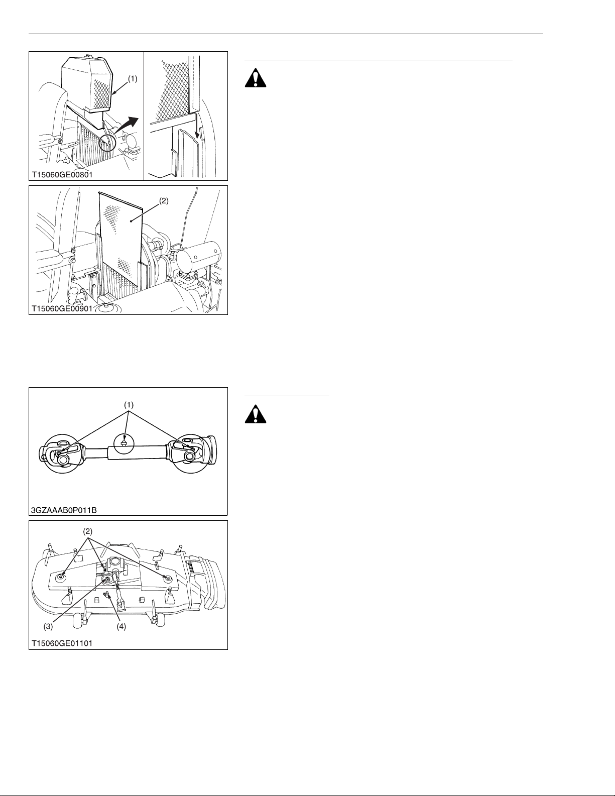
Checking and Cleaning Radiator to Prevent Overheating
CAUTION
To avoid personal injury:
• Be sure to stop the engine and remove the key before
cleaning.
Daily or after every 5 hour s of operation, check to be sure the
radiator screen and radiator core are clean. Dirt or chaff on the
radiator screen or radiator core decrease cooling performance.
1. Remove the radiator screen and panel sc reen and remo ve all
foreign material.
2. Remove the dust from between the fins and the tube.
3. Tighten the fan drive belt as necessary. For this, refer to “EVERY
100 HOURS” in Maintenance section.
4. If scale forms in the tube, clean with the scale inhibitor or its
equivalent.
5. Each time the panel screen is covered with grass during
operation, rub i t off the screen with hand. Check the radiator
screen from time to time if grass accumulates.
6. If the dust or chaff h as acc umula ted inside of the panel , remove
the radiator screen and clean inside completely.
After cleaning, replace the radiator screens properly.
NOTE
• When assembling the panel screen, be sure to fit it in the
runners.
(1) Panel Screen (2) Radiator Screen
W1043048
Greasing (Mower)
CAUTION
To avoid personal injury:
• Be sure to stop the engine and remove the key before
greasing.
1. Apply grease to the following position as figures.
(1) Mower Universal Joint
(2) Spindle Shaft
(3) Belt Tension Pulley
(4) Belt Tension Pivot
W1043490
G-16
ZD21N-EC, ZD21-EC, ZD28-EC, WSM
■
KiSC issued 09, 2006 A
[2] CHECK POINTS OF INITIAL 50 HOURS
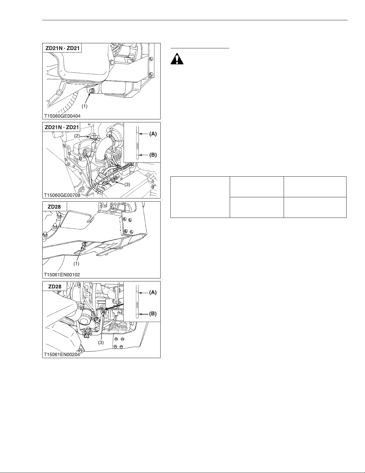
Changing Engine Oil
CAUTION
• Be sure to stop the engine before changing oil.
1. Start and warm up the engine for approx. 5 minutes.
2. Place an oil pan underneath the engine.
3. To drain the used o il, r emove the drai n plug (1) at t he botto m of
the engine and drain the oil completely.
4. Screw in the drain plug (1).
5. Fill new oil up to upper line on the dipstick (3).
IMPORTANT
• When using an oil of different manufacture or viscosity from
the previous one, remove all of the old oil.
• Never mix two different type of oil.
• Use the proper SAE engine oil according to ambient
temperatures.
Refer to “LUBRICANTS, FUEL AND COOLANT”.
(See page G-7.)
Engine oil capacity
ZD21N
ZD21
ZD28
G GENERAL
3.5 L
3.7 U.S.qts.
3.1 Imp.qts.
3.4 L
3.6 U.S.qts.
3.0 Imp.qts.
(1) Drain Plug
(2) Oil Inlet Plug
(3) Dipstick
(A) Upper Level
(B) Lower Level
W1030749
G-17
 Loading...