

Page 1
WORKSHOP
MANUAL
DIESEL
ENG'INE
Z402-EB-ONAN-1
Page 2

Page 3
TO
THE
READER
This Workshop Manual has been prepared to provide servicing personnel with
information on the service and maintenance
of
KUBOTA Diesel Engine 2402-8.
Disassembling
and
Servicing
Under the heading ”General” section comes general precautions, troubleshooting,
lists
of servicing specifications and periodic inspection items. For each engine section, there
are “Checking and Adjustment”, “Disassembling and Assembling”, and “Servicing” which
cover procedures, precautions, factory specification and allowable limits.
AI1
information, illustrations and specifications contained in this manual are based
on
The right
is
resewed to make changes in all information at any time without notice.
the latest production information available at the time of publication.
September
2000
@
KUBOTA Corporation
2000
02090Z00010
Page 4
SAFETY
INSTRUCTIONS
2402-8
WSM,
02090
A
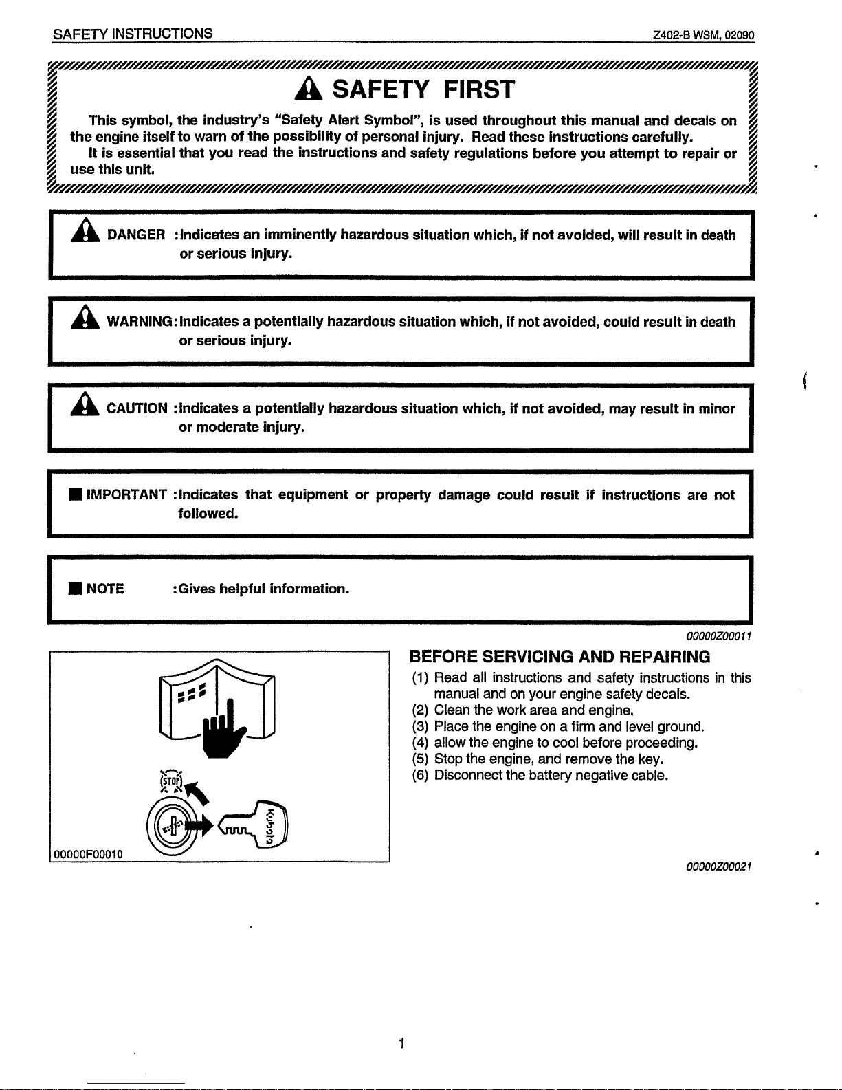
DANGER :Indicates an imminently hazardous situation which,
if
not avoided, will result
in
death
or serious injury.
i
L
~/////////~////////////////////////~/////////////////~///////////////////////////////////~////~///////~/~/////////////////f///////~
g
f
f
A
SAFETY
FIRST
This symbol, the industry’s “Safety Alert Symbol”,
is
used throughout this manual and decals on
4
It
is essential that you read the instructions and safety regulations before you attempt to repair or
f
the engine itself to warn of the possibility of personal injury. Read these instructions carefully.
use this unit.
h
I
WARNING: Indicates a potentially hazardous situation which,
if
not avoided, could result
in
death
or serious injury.
c
I
CAUTION :Indicates a potentlally hazardous situation which, if not avoided, may result
in
minor
la
or moderate injury.
IMPORTANT :Indicates that equipment or property damage could result if instructions are not
followed.
:Gives helpful information.
I
OOOOOZOOOl
1
BEFORE SERVICING
AND
REPAIRING
(1)
Read all instructions and safety instructions
in
this
manual and on your engine safety decals.
(2)
Clean the work area and engine.
(3)
Place the engine on a firm and level ground.
(4)
allow the engine to cool before proceeding.
(5)
Stop the engine, and remove the key.
(6)
Disconnect the battery negative cable.
OOOOOFOOOlO
ooooozooo21
.
1
Page 5
2402-8
WSM,
02090
SAFETY
JNSTRUCTIONS
00000F00021
00000F00030
00000F00040
A
)0000F00050
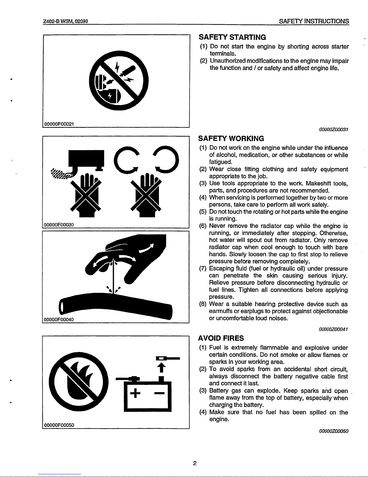
SAFETY STARTING
(1)
Do not
start
the engine by shorting across starter
terminals.
(2)
Unauthorized modifications to the engine may impair
the function and /or safety and affect engine life.
.
00000Z00031
SAFETY WORKING
(1)
Do
not work on the engine while under the influence
of alcohol, medication, or other substances or while
fatigued.
(2)
Wear close fitting clothing and safety equipment
appropriate to the job.
(3)
Use tools appropriate to the work. Makeshift tools,
parts, and procedures are not recommended.
(4)
When servicing is performed together by
two
or more
persons, take care to perform all work safely.
(5)
Do
not touch the rotating or hot parts while the engine
is running.
(6)
Never remove the radiator cap while the engine is
running, or immediately after stopping. Otherwise,
hot water
will
spout out from radiator. Only remove
radiator cap when cool enough to touch with bare
hands. Slowly loosen the cap to first stop to relieve
pressure before removing completely.
(7)
Escaping fluid (fuel or hydraulic oil) under pressure
can penetrate the skin causing serious injury.
Relieve pressure before disconnecting hydraulic or
fuel lines. Tighten all connections before applying
pressure.
(8)
Wear a suitable hearing protective device such as
earmuffs or earplugs to protect against objectionable
or uncomfortable loud noises.
I
0000020004
1
AVOID FIRES
(1)
Fuel is extremely flammable and explosive under
certain conditions.
Do
not smoke or allow flames or
sparks in your working area.
(2)
To
avoid sparks from an accidental short circuit,
always disconnect the battery negative cable first
and connect it last.
(3)
Battery gas can explode. Keep sparks and open
,
flame away from the top of battery, especially when
charging the battery.
(4)
Make sure that no fuel has been spilled
on
the
engine.
00000Z00050
2
Page 6
SAFETY INSTRUCTIONS
Z402-B
WSM,
02090
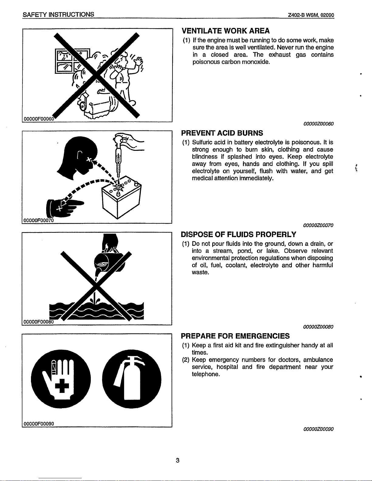
VENTILATE
WORK
AREA
(1)
If
the engine must be running to do some work, make
sure the area is well ventilated. Never run the engine
in a closed area. The exhaust gas contains
poisonous carbon monoxide.
00000Z00060
PREVENT ACID
BURNS
(1)
Sulfuric acid
in
battery electrolyte is poisonous. It is
strong enough to burn skin, clothing and cause
blindness
if
splashed into eyes. Keep electrolyte
away from eyes, hands and clothing.
If
you spill
electrolyte on yourself, flush with water, and get
medical attention immediately.
00000Z00070
DISPOSE
OF
FLUIDS PROPERLY
(1)
Do
not pour fluids into the ground, down a drain, or
into a stream, pond, or lake. Observe relevant
environmental protection regulations when disposing
of
oil,
fuel, coolant, electrolyte and other harmful
waste.
00000Z00080
PREPARE
FOR
EMERGENCIES
[I
(1)
Keep a first aid kit and fire extinguisher handy at all
._
-
times.
(2)
Keep emergency numbers for doctors, ambulance
service, hospital and fire department near your
telephone.
OOOOOFOOO9O
00000200090
3
Page 7
ZW-B
LVS?J,
02090
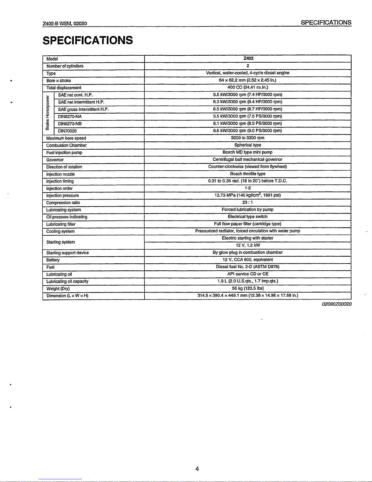
SPEClFlCATl
ONS
~~~ ~
Number
of
cylinders
Tw
Bore
xstroke
SPECIFICATIONS
~ ~~~
2
Vertical,
Water-cooled, 4-cycle diesel engine
64
x
62.2
mm
(252 x 245
in.)
I
Model
I
2402
I
Total displacement
SAE net cont. H.P.
SAE net intermittent H.P.
n
2
SAE gross intermitlent H.P.
2
DIN6270-NA
DIN6270-NB
'
DIN70020
Maximum bare speed
Combustion Chamber
Fuel injection pump
Governor
Direction of rotation
Injection nozzle
Injection timing
Injection pressure
Compression ratio
Lubricating system
Oil pressure indicating
Lubricating filter
Cooling system
Starting system
Starting support device
Bettely
Fuel
Lubricating oil
Lubricating oil capacity
Weight
(Dry)
Dimension (L
x
W
x
H)
~~ ~
Injection order
400 CC (24.41 cu.in.)
5.5 kW/3000
rpm
(7.4 HPl3000
rpm)
6.3 kW/3000
rpm
(8.4 HP/3000
rpm)
6.5 kW/3000
rpm
(8.7 HP/3000
rpm)
5.5 kW13000
rpm
(7.5 PS/3000
rpm)
6.1 kW/3000
rpm
(8.3 PS/3000
rpm)
6.6 kW/3000
rpm
(9.0
PS/3000
rpm)
3200 to 3300
rpm
Spherical type
Bosch MD
type
mini pump
Centrifugal ball mechanical governor
Counter-clockwise (viewed from flywheel)
Bosch throttle type
0.31 to 0.35 rad. (18 to 20') before T.D.C.
1
-2
13.73 MPa (140 kgf/crn2, 1991 psi)
23:
1
Forced lubrication by pump
Electrical type switch
Full flow paper filter (cartridge
type)
Pressurized radiator, forced circulation with water pump
Electric starting with starter
12
V,
1.2 kW
By glow plug
in
combustion chamber
12
V,
CCA
600,
equivalent
Diesel fuel No. 2-D (ASTM D975)
API service CD or CE
1.9
L
(2.0 U.S.qts.,
1.7
Imp.qts.)
56 kg (123.5 Ibs)
314.5
x
380.4 x 449.1
mm
(12.38 x 14.98 x 17.68 in.)
~~
~ ~~
02090Z00020
4
Page 8
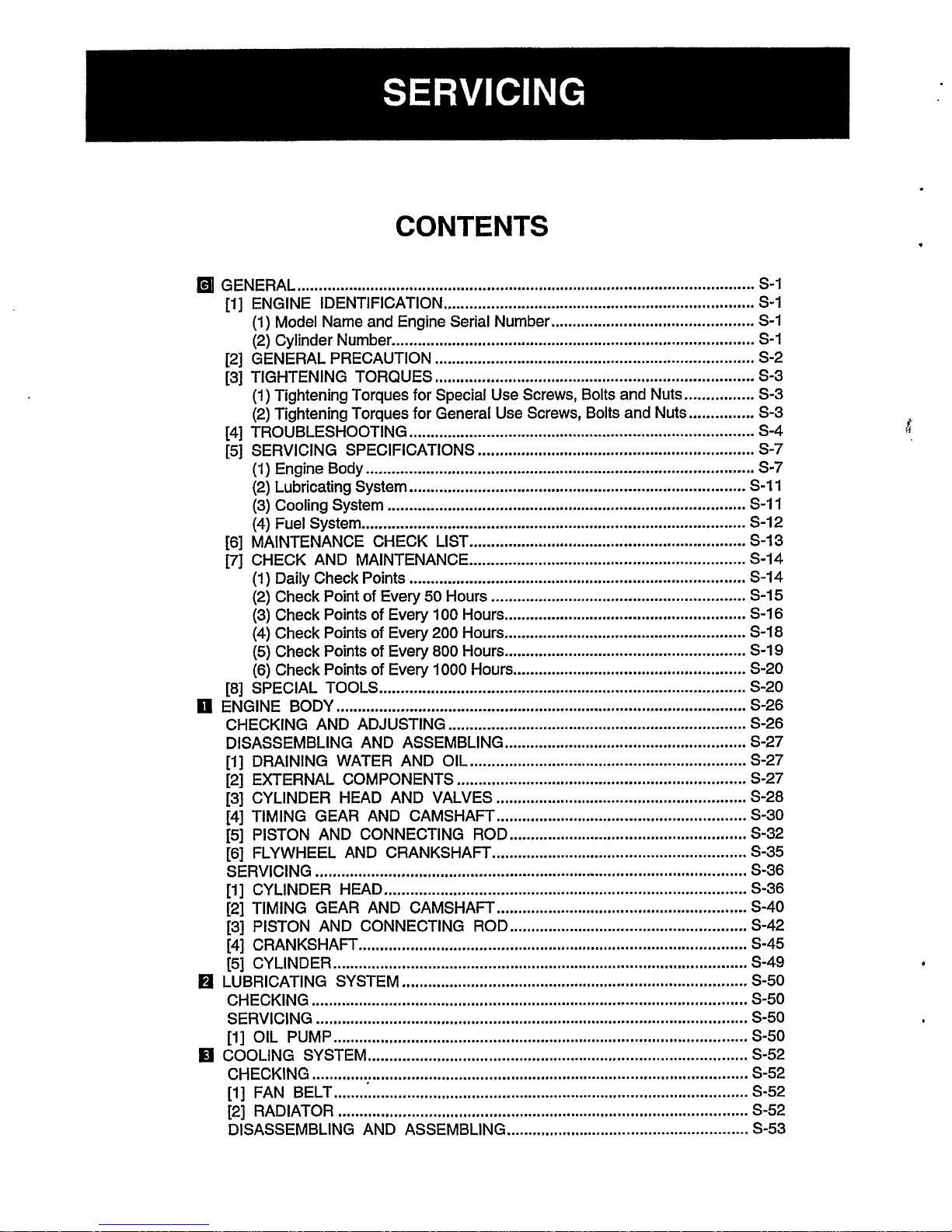
CONTENTS
GENERAL
..........................................................................................................
S-I
[I]
ENGINE IDENTIFICATION
........................................................................
5-1
(1)
Model Name and Engine Serial Number
...............................................
5-1
(2) Cylinder Number
....................................................................................
5-1
(1)
Tightening Torques for Special Use Screws. Bolts and Nuts
................
5-3
[2] GENERAL PRECAUTION
..........................................................................
5-2
[3] TIGHTENING TORQUES
..........................................................................
5-3
(2) Tightening Torques for General Use Screws. Bolts and Nuts
...............
5-3
[4] TROUBLESHOOTING
................................................................................
5-4
[5] SERVICING SPECIFICATIONS
................................................................
5-7
(1)
Engine Body
..........................................................................................
5-7
(3)
Cooling System
...................................................................................
5-11
(4)
Fuel System
.........................................................................................
5-12
(1)
Daily Check Points
..............................................................................
5-14
(2)
Check Point of Every
50
Hours
...........................................................
5-15
(2)
Lubricating System
..............................................................................
5-11
[6]
MAINTENANCE CHECK LIST
................................................................
5-13
[71
CHECK AND MAINTENANCE
................................................................
5-14
(3) Check Points
of
Every
100
Hours
........................................................
5-16
(4) Check Points of Every 200 Hours
........................................................
5-18
(5)
Check Points
of
Every 800 Hours
........................................................
5-19
(6) Check Points of Every 1000 Hours
......................................................
5-20
[8] SPECIAL TOOLS
.....................................................................................
5-20
0
ENGINE BODY
...............................................................................................
5-26
CHECKING AND ADJUSTING
.....................................................................
5-26
DISASSEMBLING AND ASSEMBLING
........................................................
5-27
[I]
DRAINING WATER AND OIL
................................................................
5-27
[23
EXTERNAL COMPONENTS
...................................................................
5-27
[3] CYLINDER HEAD AND VALVES
..........................................................
5-28
[4]
TIMING GEAR AND CAMSHAFT
..........................................................
5-30
[5] PISTON AND CONNECTING ROD
.......................................................
5-32
[6] FLYWHEEL AND CRANKSHAFT
...........................................................
5-35
SERVICING
....................................................................................................
5-36
[I]
CYLINDER HEAD
....................................................................................
5-36
[2] TIMING GEAR AND CAMSHAFT
..........................................................
5-40
[3] PISTON AND CONNECTING ROD
.......................................................
5-42
[4] CRANKSHAFT
..........................................................................................
5-45
[5] CYLINDER
................................................................................................
5-49
IEl
LUBRICATING SYSTEM
................................................................................
5-50
CHECKING
.....................................................................................................
5-50
SERVICING
....................................................................................................
5-50
[I]
OIL PUMP
................................................................................................
5-50
IF1
COOLING SYSTEM
........................................................................................
5-52
CHECKING
.....................................................................................................
5-52
[I]
FAN BELT
................................................................................................
5-52
[2]
RADIATOR
...............................................................................................
5-52
DISASSEMBLING AND ASSEMBLING
........................................................
S-53
A
*
Page 9
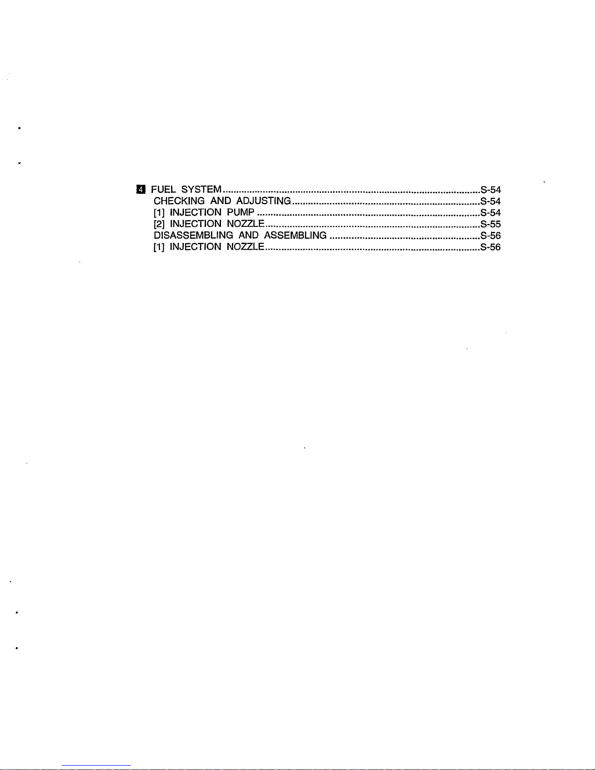
FUEL SYSTEM
................................................................................................
5-54
CHECKING AND ADJUSTING
......................................................................
5-54
[i]
INJECTION PUMP
...................................................................................
5-54
[2]
INJECTION NOZZLE
................................................................................
5-55
DISASSEMBLING AND ASSEMBLING
........................................................
5-56
[I]
INJECTION NOZZLE
................................................................................
5-56
Page 10
DIESEL ENGINE
2402-B
WSM,
02090
GENERAL
[I]
ENGINE
IDENTIFICATION
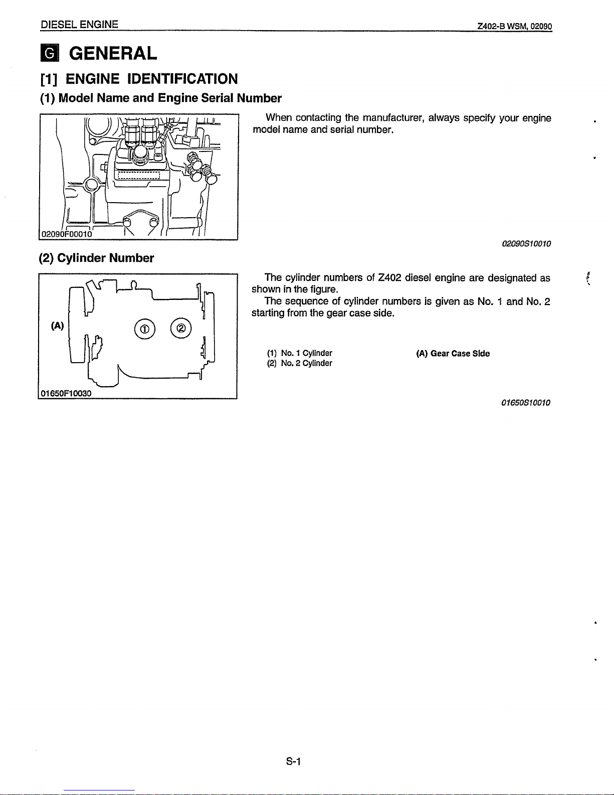
(1)
Model
Name and Engine Serial Number
When contacting the manufacturer, always specify your engine
model name and serial number.
02090510010
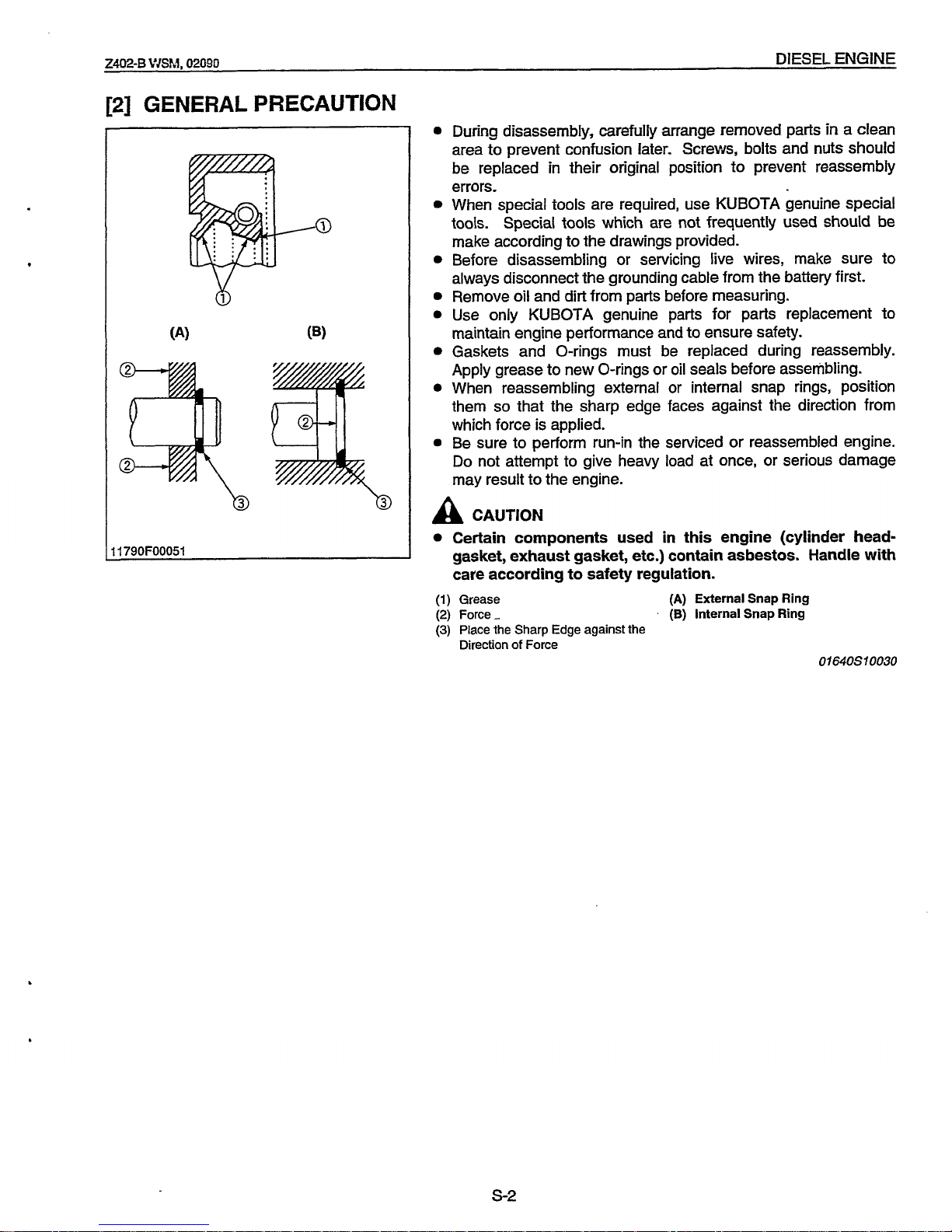
(2)
Cylinder Number
The cylinder numbers of
2402
diesel engine are designated as
The sequence of cylinder numbers
is
given as No. 1 and
No.
2
shown
in
the figure.
starting from the gear case side.
c
t
(1)
No.
1
Cylinder
(2)
No.
2
Cylinder
(A)
Gear Case Side
01650510010
.
s-1
Page 11
Z4M-B
VJSM.
02090
DIESEL
ENGINE
[Z]
GENERAL
PRECAUTION
11790F00051
0
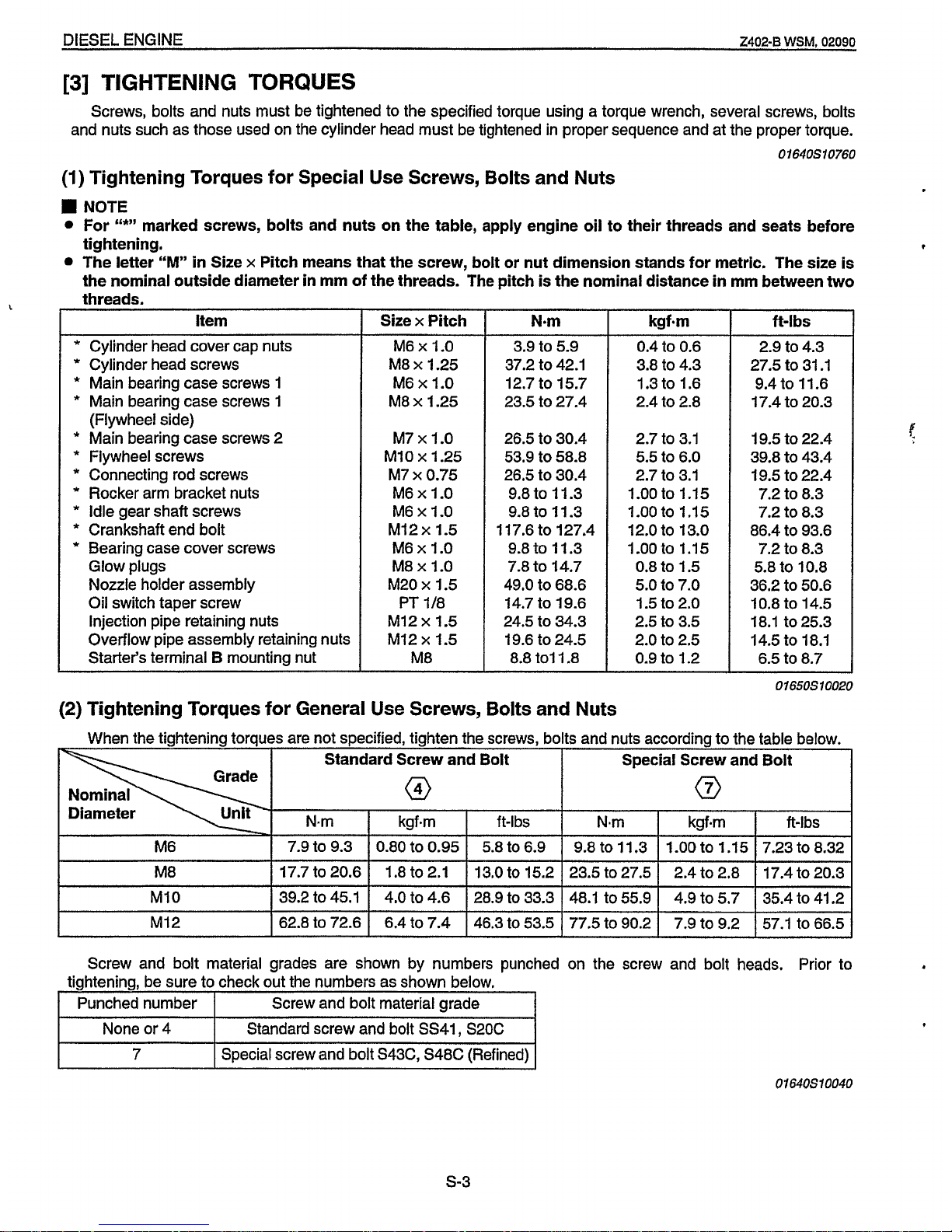
During disassembly, carefully arrange removed parts
in
a
clean
area to prevent confusion later. Screws, bolts and nuts should
be replaced in their original position to prevent reassembly
errors.
When special tools are required, use KUBOTA genuine special
tools.
Special
tools
which are not frequently used should be
make according to the drawings provided.
Before disassembling or servicing live wires, make sure to
always disconnect the grounding cable from the battery first.
Remove
oil
and dirt from parts before measuring.
Use only KUBOTA genuine parts for parts replacement to
maintain engine performance and to ensure safety.
Gaskets and O-rings must be replaced during reassembly.
Apply grease to new O-rings or
oil
seals before assembling.
When reassembling external or internal snap rings, position
them
so
that the sharp edge faces against the direction from
which force is applied.
0
Be sure to perform run-in the serviced or reassembled engine.
Do
not attempt to give heavy load at once, or serious damage
may result to the engine.
A
CAUTION
Certain components used in this engine (cylinder headgasket, exhaust gasket, etc.) contain asbestos. Handle with
care according to safety regulation.
(1)
Grease
(2)
Force-
(3)
Place the Sharp Edge against the
Direction
of
Force
(A)
External Snap Ring
(B)
internal Snap Ring
01
64051
0030
s-2
Page 12
DIESEL ENGINE
2402-6
WSM,
02090
[3]
TIGHTENING
TORQUES
Screws, bolts and nuts must be tightened to the specified torque using a torque wrench, several screws, bolts
and nuts such as those used on the cylinder head must be tightened in proper sequence and at the proper torque.
01640S10760
(1)
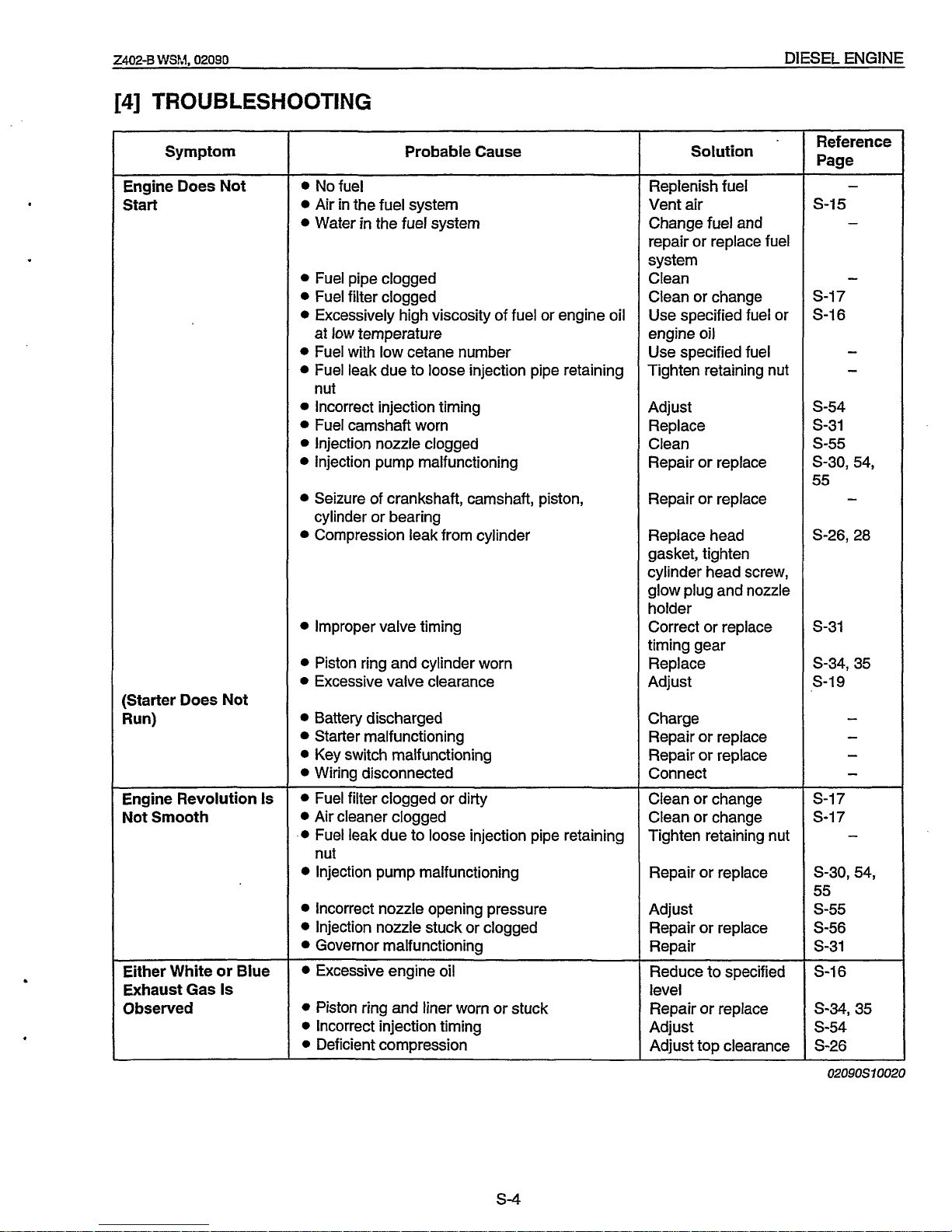
Tightening Torques for Special Use Screws, Bolts and Nuts
NOTE
For
“*”
marked screws, bolts and nuts on the table,
apply
engine oil to their threads and seats before
tightening.
t
The letter
“M”
in Size x Pitch means that the screw, bolt or nut dimension stands for metric. The size is
the nominal outside diameter in mm of the threads. The pitch is the nominal distance in mm between two
threads.
Standard Screw and Bolt
@
Item
Special Screw and Bolt
Q
*
Cylinder head cover cap nuts
*
Cylinder head screws
*
Main bearing case screws
1
*
Main bearing case screws
1
(Flywheel side)
*
Main bearing case screws
2
*
Flywheel screws
*
Connecting rod screws
*
Rocker arm bracket nuts
*
Idle gear shaft screws
*
Crankshaft end bolt
*
Bearing case cover screws
Glow plugs
Nozzle holder assembly
Oil switch taper screw
Injection pipe retaining nuts
Overflow pipe assembly retaining nuts
Starter’s terminal
B
mounting nut
N-m kgf.m ft-lbs
Diameter
M6
7.9
to
9.3 0.80
to
0.95 5.8
to
6.9
Size x Pitch
Nmm kgf.m ft-lbs
9.8
to
11.3
1-00
to
1.15
7.23
to
8.32
M6
x
1.0
M8 x 1.25
M6
x
1.0
M8 x 1.25
M7
x
1.0
MI0
x
1.25
M7
x
0.75
M6
x
1.0
M6 x 1.0
MI2
x
1.5
M6x
1.0
M8 x 1.0
M20 x 1.5
PT
118
MI2
x
1.5
MI2
x
1.5
M8
MI0
MI2
N.m
39.2
to
45.1 4.0
to
4.6
28.9
to
33.3 48.1
to
55.9 4.9
to
5.7
35.4
to
41.2
62.8
to
72.6 6.4
to
7.4
46.3
to
53.5 77.5
to
90.2 7.9
to
9.2
57.1
to
66.5
3.9
to
5.9
37.2
to
42.1
12.7
to
15.7
23.5
to
27.4
None or
4
7
26.5
to
30.4
53.9
to
58.8
26.5
to
30.4
9.8
to
11.3
9.8
to
11.3
117.6
to
127.4
9.8
to
11.3
7.8
to
14.7
49.0
to
68.6
14.7
to
19.6
24.5
to
34.3
19.6
to
24.5
8.8
to1
1.8
Standard screw and bolt
SS41
,
S20C
Special screw and bolt
S43C,
S48C
(Refined)
kgfam
0.4
to
0.6
3.8
to
4.3
1.3
to
1.6
2.4
to
2.8
2.7
to
3.1
5.5
to
6.0
2.7
to
3.1
1.00
to
1.15
1.00
to
1.15
12.0
to
13.0
1.00
to
1.15
0.8
to
1.5
5.0
to
7.0
1.5
to
2.0
2.5
to
3.5
2.0
to
2.5
0.9
to
1.2
ft-lbs
2.9
to
4.3
27.5
to
31
.I
9.4
to
11.6
17.4
to
20.3
19.5
to
22.4
39.8
to
43.4
19.5
to
22.4
7.2
to
8.3
7.2
to
8.3
86.4
to
93.6
7.2
to
8.3
5.8
to
10.8
36.2
to
50.6
10.8
to
14.5
18.1 to25.3
14.5
to
18.1
6.5
to
8.7
01650510020
(2)
Tightening Torques for General Use Screws, Bolts and Nuts
I I
I
I
I
I
M8
I
17.7
to
20.6 I 1.8
to
2.1
I
13.0
to
15.2 I 23.5 to27.5 I 2.4
to
2.8 I 17.4
to
20.3
I
Screw and bolt material grades are shown by numbers punched on the screw and bolt heads. Prior to
tightening, be sure to check out the numbers as shown below.
I
Punchednumber
I
Screw and bolt material grade
0164OS10040
5-3
Page 13
zm-B
WSM.
02090
DIESEL
ENGINE
[4]
TROUBLESHOOTING
Symptom
Engine
Does
Not
Start
(Starter
Does
Not
Run)
~
Engine Revolution
Is
Not
Smooth
Either White
or
Blue
Exhaust
Gas
Is
0
bserved
Probable Cause
Nofuel
Air
in the fuel system
Water in the fuel system
Fuel pipe clogged
Fuel filter clogged
Excessively high viscosity of fuel or engine oil
at low temperature
Fuel with low cetane number
Fuel leak due to loose injection pipe retaining
Incorrect injection timing
Fuel camshaft worn
Injection nozzle clogged
Injection pump malfunctioning
nut
Seizure of crankshaft, camshaft, piston,
Compression leak from cylinder
cylinder or bearing
Improper valve timing
Piston ring and cylinder worn
0
Excessive valve clearance
Battery discharged
Starter malfunctioning
Key switch malfunctioning
Wiring disconnected
Fuel filter clogged or dirty
Air cleaner clogged
Fuel leak due to loose injection pipe retaining
Injection pump malfunctioning
nut
Incorrect nozzle opening pressure
Injection nozzle stuck or clogged
Governor malfunctioning
Excessive engine
oil
0
Piston ring and liner worn or stuck
0
Incorrect injection timing
0
Deficient compression
Solution
Replenish fuel
Vent air
Change fuel and
repair or replace fuel
system
Clean
Clean or change
Use specified fuel or
engine
oil
Use specified fuel
Tighten retaining nut
Adjust
Replace
Clean
Repair or replace
Repair or replace
Replace head
gasket, tighten
cylinder head screw,
glow plug and nozzle
holder
Correct or replace
timing gear
Replace
Adjust
Charge
Repair or replace
Repair or replace
Connect
Clean or change
Clean or change
Tighten retaining nut
Repair or replace
Adjust
Repair or replace
Repair
Reduce
to
specified
level
Repair or replace
Adjust
Adjust top clearance
Reference
Page
-
S-15
-
-
S-17
S-16
-
-
s-54
S-31
s-55
S-30,
54,
55
-
S-26,28
S-31
s-34, 35
s-19
-
-
-
-
S-17
S-17
-
S-30,54,
55
s-55
S-56
S-31
S-16
s-34,35
s-54
S-26
02090S70020
5-4
Page 14
DIESEL ENGINE
2402-8
WSM,
02090
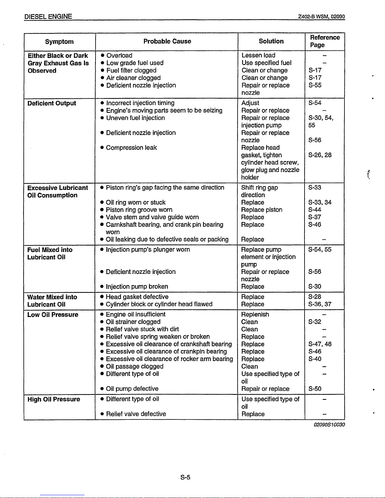
Either Black or Dark
Gray Exhaust Gas Is
Observed
Deficient Output
Excessive Lubricant
Oil
Consumption
Fuel Mixed into
Lubricant
Oil
Water Mixed into
Lubricant Oil
Low
Oil
Pressure
~~
High Oil Pressure
Probable Cause
Overload
0
Low grade fuel used
Fuel filter clogged
Air cleaner clogged
0
Deficient nozzle injection
0
Incorrect injection timing
0
Engine’s moving parts seem to be seizing
0
Uneven fuel injection
Deficient nozzle injection
Compression leak
0
Piston ring’s gap facing the same direction
Oil ring worn or stuck
Piston ring groove worn
0
Valve stem and valve guide worn
Carnkshaft bearing, and crank pin bearing
0
Oil leaking due to defective seals or packing
worn
Injection pump’s plunger worn
0
Deficient nozzle injection
0
Injection pump broken
Head gasket defective
0
Cylinder block or cylinder head flawed
__
~-~
0
Engine oil insufficient
0
Oil strainer clogged
0
Relief valve stuck with dirt
0
Relief valve spring weaken or broken
0
Excessive oil clearance of crankshaft bearing
0
Excessive oil clearance of crankpin bearing
0
Excessive oil clearance of rocker arm bearing
Oil passage clogged
Different type of oil
0
Oil pump defective
0
Different type of oil
0
Relief valve defective
Solution
Lessen load
Use specified fuel
Clean or change
Clean or change
Repair
or
replace
nozzle
Adjust
Repair or replace
Repair or replace
injection pump
Repair or replace
nozzle
Replace head
gasket, tighten
cylinder head screw,
glow plug and nozzle
holder
Shift ring gap
direction
Replace
Replace piston
Replace
Replace
Replace
Replace pump
element or injection
Pump
Repair
or
replace
nozzle
Replace
Replace
Replace
Replenish
Clean
Clean
Replace
Replace
Replace
Replace
Clean
Use specified type of
oil
Repair or replace
Use specified type of
oil
Replace
Reference
Page
8.-
-
S-17
S-17
5-55
5-54
5-30, 54,
55
5-56
S-26,28
-
5-33
s-33,
34
s-44
s-37
S-46
-
5-54,55
S-56
5-30
5-28
S-36’37
-
S-32
-
c
S-47,40
S-46
5-40
-
-
5-50
.
02090510030
5-5
Page 15
DIESEL
ENGINE
2402-6
WSM.
02090
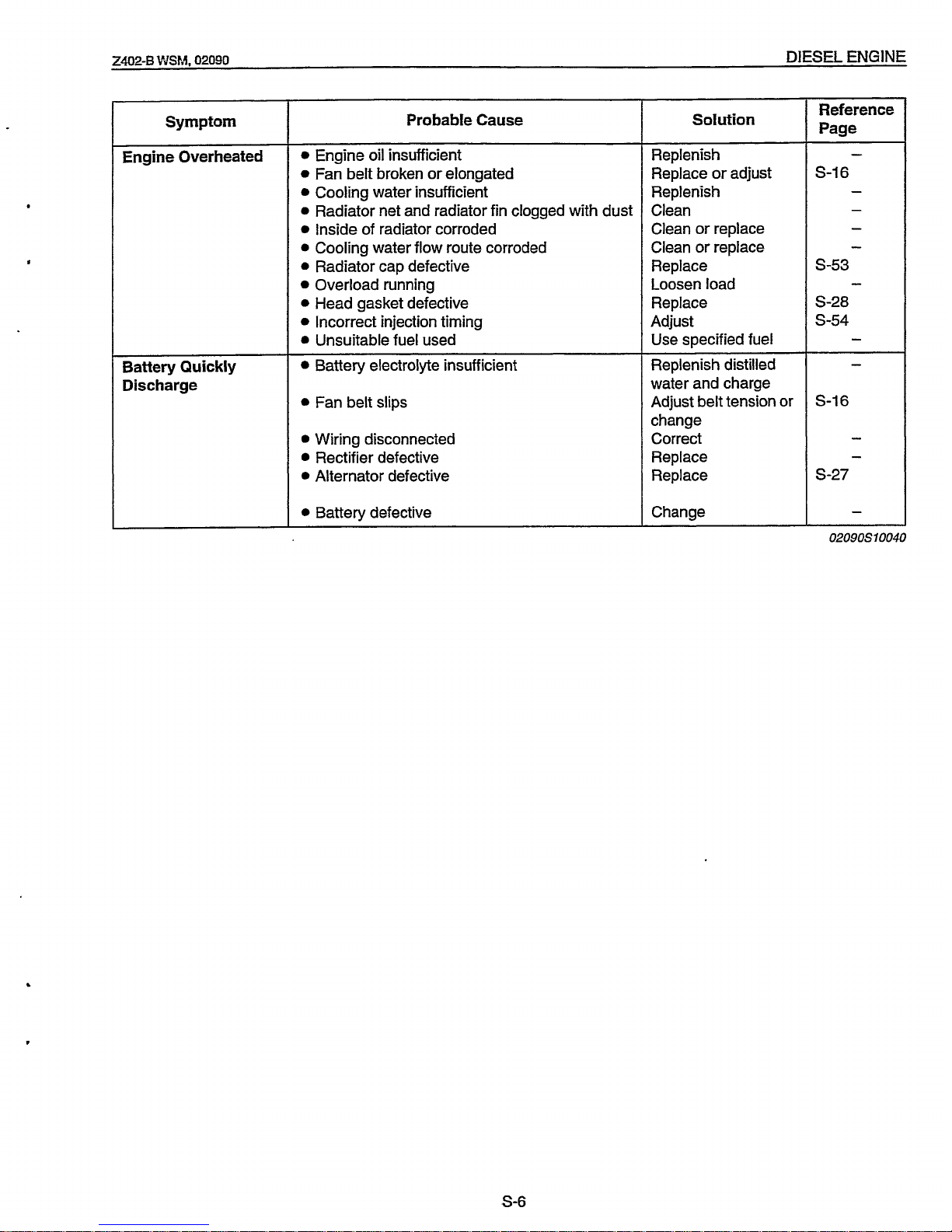
Symptom
Engine Overheated
Battery Quickly
Discharge
Probable Cause
0
Engine
oil
insufficient
0
Fan belt broken
or
elongated
0
Cooling water insufficient
0
Radiator net and radiator fin clogged with dust
0
Inside
of
radiator corroded
0
Cooling water flow
route
corroded
0
Radiator cap defective
Overload running
0
Head gasket defective
0
Incorrect injection timing
0
Unsuitable
fuel
used
Battery electrolyte insufficient
0
Fan belt slips
Wiring disconnected
Rectifier defective
0
Alternator defective
0
Battery defective
Solution
Replenish
Replace or adjust
Replenish
Clean
Clean or replace
Clean
or
replace
Replace
Loosen load
Replace
Adjust
Use
specified
fuel
Replenish distilled
water and charge
Adjust belt tension or
change
Correct
Replace
Replace
Change
Reference
Page
-
S-16
-
-
-
-
s-53
S-28
s-54
-
-
02090510040
S-6
Page 16
DIESEL
ENGINE
2402-8
WSM,
02090
Variance Among Cylinders
-
I
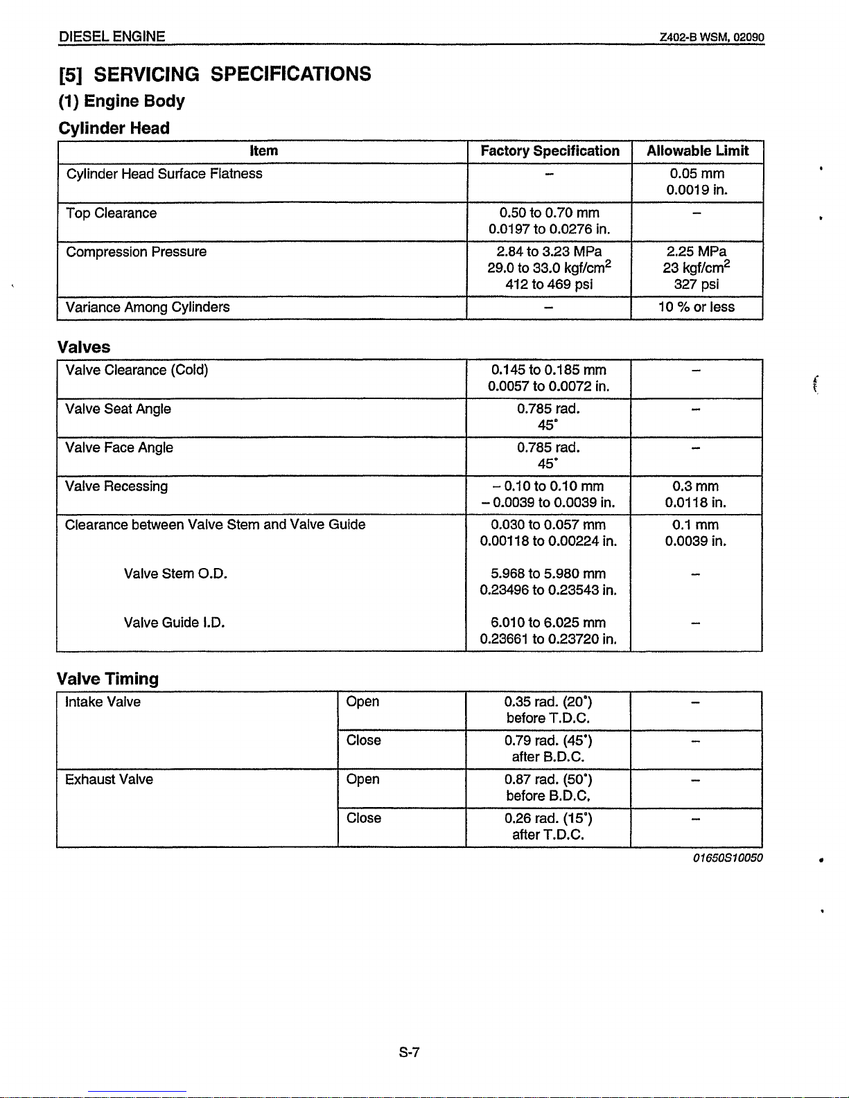
[5]
SERVICING
SPECIFICATIONS
10
%or less
(1)
Engine Body
Cvlinder Head
0.1 45 to
0.1
85
mm
0.0057
to
0.0072 in.
0.785 rad.
45"
0.785 rad.
45'
Cylinder Head Surface Flatness
Top
Clearance
-
-
Factory Specification
-
Open
Close
0.50
to 0.70 mm
0.0197 to 0.0276 in.
0.35 rad.
(20")
-
before T.D.C.
0.79 rad. (45')
after B.D.C.
-
Allowable Limit
0.05
mm
0.0019 in.
Close
Compression Pressure
0.26 rad.
(15')
-
after T.D.C.
2.84 to 3.23 MPa
29.0
to
33.0 kgf/cm2
412 to 469 psi
2.25 MPa
23 kgflcm2
327 psi
Valves
I
Valve Clearance (Cold)
Valve Seat Angle
Valve Face Angle
I
Valve Recessing
Clearance between Valve Stem and Valve Guide
Valve Stem O.D.
Valve Guide I.D.
Valve Timing
-
Intake Valve
Exhaust Valve
-
0.10
to
0.10
mm
-
0.0039 to 0.0039 in.
0.030
to 0.057 mm
0.3 mm
0.01
18
in.
0.1
mm
+
0.001
18 to 0.00224
in.
0.0039 in.
5.968 to
5.980
mm
0.23496 to 0.23543 in.
6.010 to 6.025 mm
0.23661 to 0.23720 in.
Open
0.87 rad.
(50')
1
before B.D.C.
-
I
.
s-7
Page 17
ZM2-B
LVSM,
02090
DIESEL
ENGINE
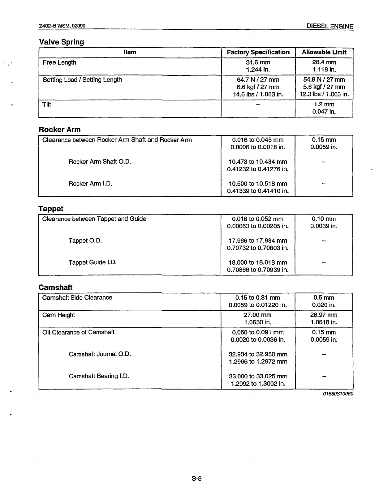
Factory
Specification
31.6
mm
1.244
in.
64.7
N
/
27
mm
6.6
kgf
/
27
mm
14.6
Ibs
/
1.063
in.
-
i.
Aliowable
Limit
28.4mm
1.118
in.
54.9 N /
27 mm
5.6
kgf
/
27 mm
12.3
Ibs
/
1.063
in.
1.2 mm
0.047
in.
Valve Spring
Clearance between Rocker Arm Shaft and Rocker Arm
0.016
to
0.045 mm
0.0006
to
0.0018
in.
Item
0.15 mm
0.0059
in.
Free Length
Set€ing Load
/
Setting Length
Rocker Arm
I.D.
10.500
to
10.51 8
mm
0.41339
to
0.4141
0
in.
Tilt
Clearance between Tappet and Guide
0.016
to
0.052
mm
0.00063
to
0.00205
in.
0.10
mm
0.0039
in.
Tappet Guide I.D.
Rocker Arm Shaft O.D.
18.000
to
18.01 8 mm
0.70866
to
0.70939
in.
-
10.473
to
10.484
mm
0.41232
to
0.41276
in.
Camshaft Side Clearance
0.15
to
0.31
mm
0.0059
to
0.01220
in.
Cam Height
27.00
mm
1.0630
in.
Oil Clearance of Camshaft
0.050
to
0.091
mm
0.0020
to
0.0036
in.
32.934
to
32.950
mm
1.2966
to
1.2972
mm
33.000
to
33.025
mm
1.2992
to
1.3002
in.
Camshaft Journal
O.D.
Camshaft Bearing
I.D.
0.5
mm
0.020
in.
26.97mm
1.061 8
in.
0.15 mm
0.0059
in.
-
-
Tappet O.D.
17.966
to
17.984
mm
0.70732
to
0.70803
in.
.
Page 18
DIESEL
ENGINE
2402-B
WSM, 02090
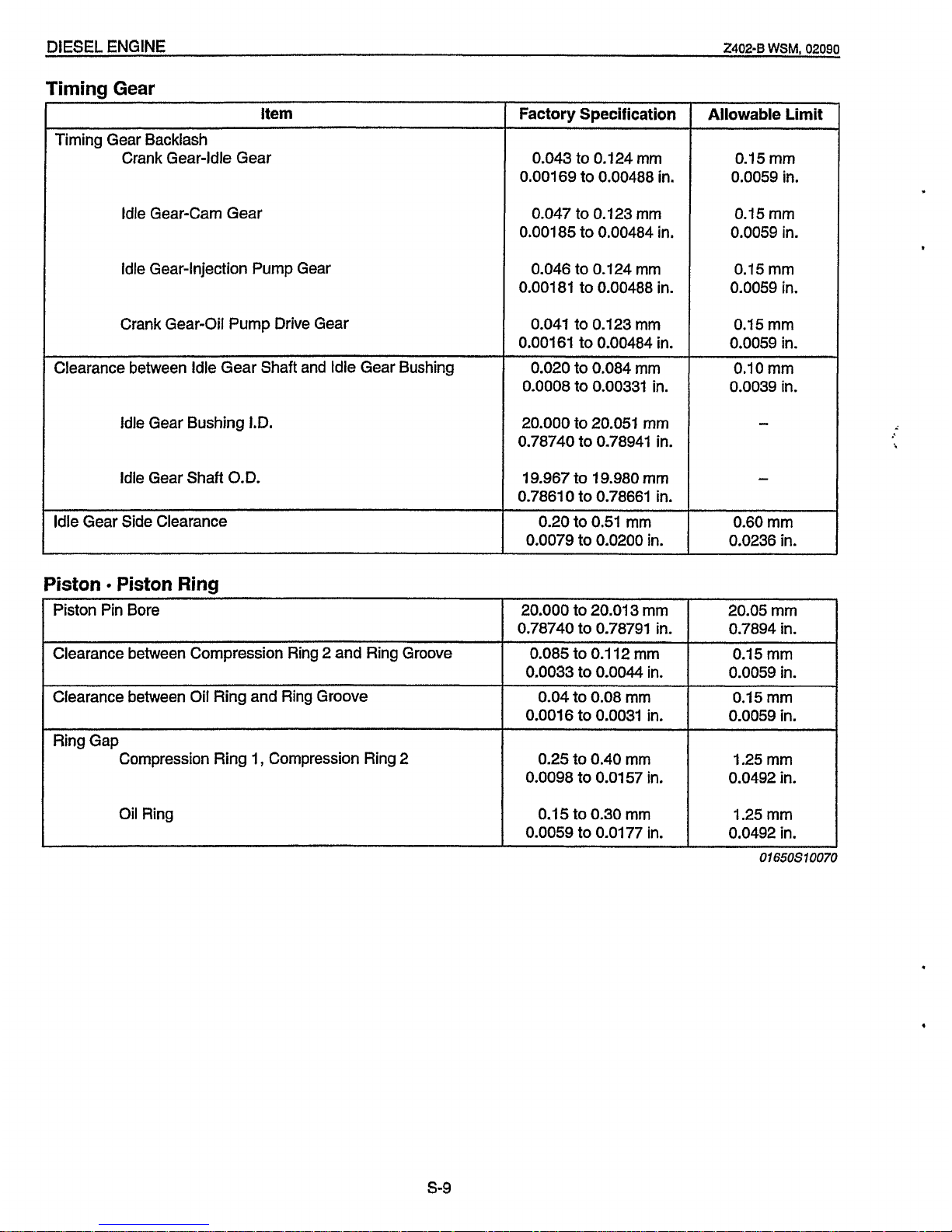
Piston Pin Bore
Clearance between Compression Ring
2
and Ring Groove
Timing
Gear
20.000
to
20.01 3 mm
0.78740
to
0.78791
in.
0.085
to
0.1
12 mm
0.0033
to
0.0044
in.
20.05
mm
0.7894
in.
0.15
mm
0.0059 in.
item
Clearance between Oil Ring and Ring Groove
Ring Gap
Compression Ring
1,
Compression Ring
2
Timing Gear Backlash
Crank Gear-Idle Gear
Idle Gear-Cam Gear
Idle Gear-Injection Pump Gear
Crank Gear-Oil Pump Drive Gear
0.04
to 0.08 mm
0.0016
to
0.0031
in.
0.25
to
0.40
mm
0.0098 to
0.01
57 in.
Clearance between Idle Gear Shaft and Idle Gear Bushing
Idle Gear Bushing I.D.
Idle Gear Shaft
O.D.
Idle Gear Side Clearance
Piston Piston
Ring
Factory Specification
0.043 to 0.124
mm
0.001
69 to 0.00488
in.
0.047
to
0.123 mm
0.001
85 to 0.00484 in.
0.046 to 0.124 mm
0.00181
to
0.00488 in.
0.041 to 0.123
mm
0.001
61
to
0.00484 in.
0.020
to
0.084 mm
0.0008 to 0.00331 in.
20.000 to 20.051 mm
0.78740 to 0.78941 in.
19.967
to
19.980 mm
0.7861
0
to
0.78661
in.
0.20
to
0.51
mm
0.0079
to
0.0200
in.
Allowable Limit
0.15 mm
0.0059 in.
0.15 mm
0.0059 in.
0.15
mm
0.0059 in.
0.15 mm
0.0059 in.
0.10
mm
0.0039
in.
-
-
0.60 mm
0.0236
in.
Oil Ring
0.15
to 0.30 mm
0.0059 to
0.01
77
in.
I
0.15
mm
0.0059 in.
1.25mm
0.0492 in.
1.25 mm
0.0492 in.
Of650S10070
s-9
Page 19
Z402-B
WSM,
02080
DIESEL ENGINE
8
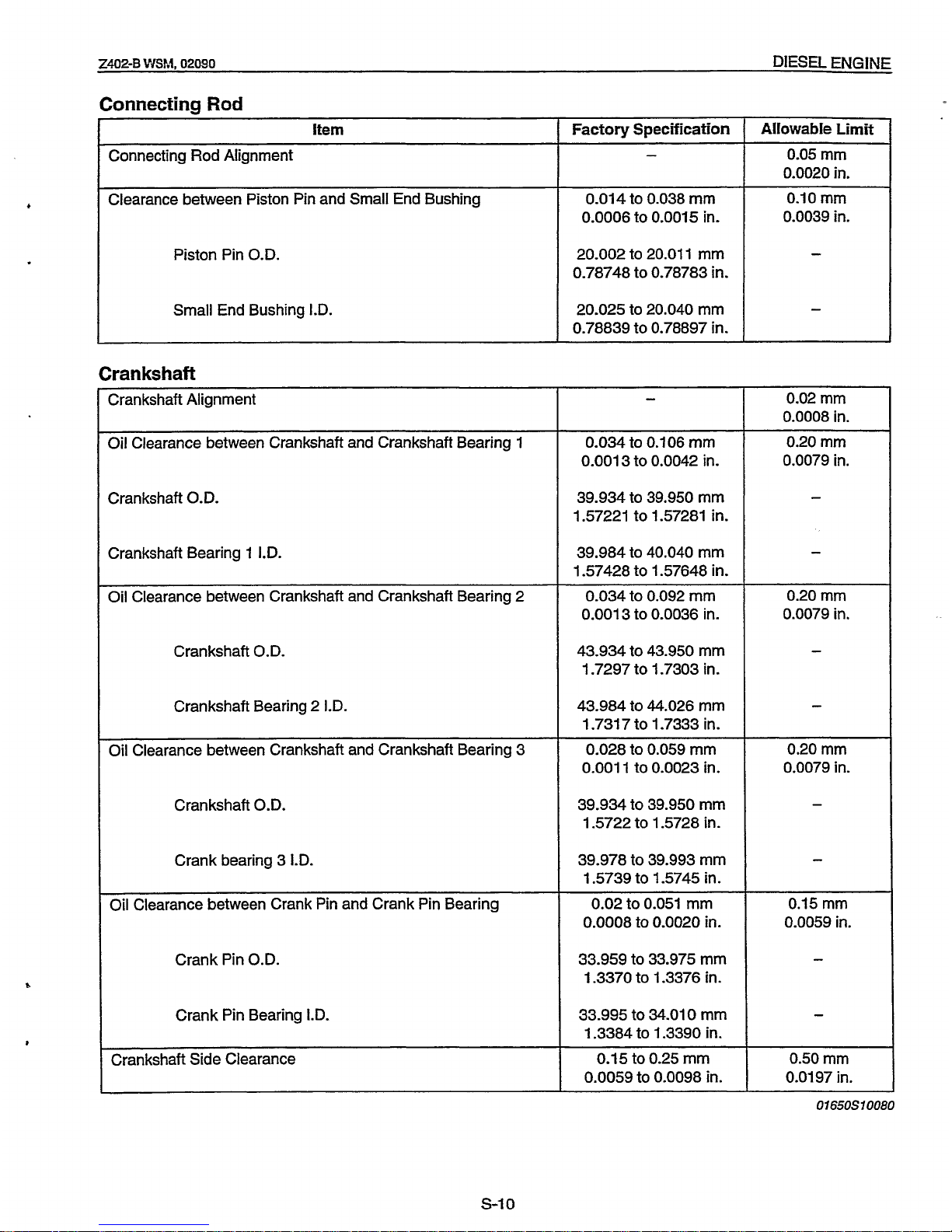
Connecting
Rod
I
item
1
Factory
Specification
I
Allowable
Limit
-
I
I
Connecting Rod Alignment
0.05 mm
0.0020 in.
Clearance between Piston Pin and Small End Bushing
Piston Pin
O.D.
Small End Bushing
I.D.
0.014
to 0.038 mm
0.0006 to 0.0015
in.
20.002 to 20.01 1 mm
0.78748 to 0.78783
in.
20.025 to 20.040 mm
0.78839 to 0.78897
in.
0.10 mm
0.0039 in.
Crankshaft
Crankshaft Alignment
Oil Clearance between Crankshaft and Crankshaft Bearing
1
Crankshaft
O.D.
Crankshaft Bearing 1
I.D.
Oil Clearance between Crankshaft and Crankshaft Bearing 2
Crankshaft
O.D.
Crankshaft Bearing 2
I.D.
Oil Clearance between Crankshaft and Crankshaft Bearing 3
Crankshaft
O.D.
Crank bearing 3
I.D.
Oil Clearance between Crank Pin and Crank Pin Bearing
Crank Pin
O.D.
Crank Pin Bearing
I.D.
Crankshaft Side Clearance
0.034
to
0.1
06 mm
0.001 3 to 0.0042
in.
39.934 to 39.950 mm
1.57221 to 1.57281
in.
39.984 to 40.040 mm
1.57428 to 1.57648
in.
0.034 to 0.092 mm
0.001
3 to 0.0036
in.
43.934 to 43.950 mm
1.7297 to 1.7303 in.
43.984 to 44.026 mm
1.731
7 to 1.7333
in.
0.028 to 0.059 mm
0.001
1
to 0.0023
in.
39.934 to 39.950 mm
1.5722 to 1.5728 in.
39.978 to 39.993 mm
1.5739 to 1.5745 in.
0.02
to 0.051 mm
0.0008 to
0.0020
in.
33.959 to 33.975 mm
1.3370 to 1.3376 in.
33.995 to 34.010 mm
1.3384 to 1.3390
in.
0.15 to 0.25 mm
0.0059 to 0.0098
in.
0.02
mm
0.0008 in.
0.20
mm
0.0079 in.
0.20
mm
0.0079 in.
0.20
mm
0.0079 in.
-
-
0.15
mm
0.0059 in.
0.50 mm
0.01
97
in.
01
650s
10080
s-10
Page 20
DIESEL
ENGINE
2402-9
WSM,
02090
Item Factory
Specification
64.000
to
64.01 9
mm
2.51 99
to
2.5204
in.
+
0.5
mm
+
0.01
97
in.
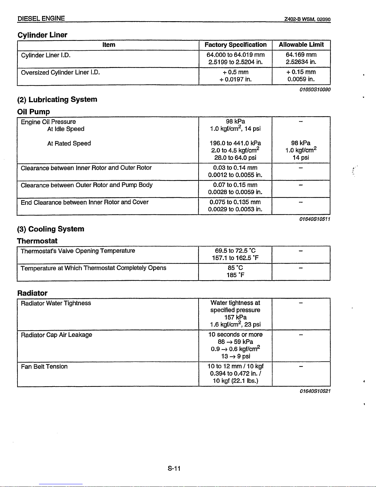
Cylinder Liner I.D.
Oversized Cylinder Liner
1.D.
Allowable Limit
64,169
mm
2.52634
in.
+
0.15
mm
0.0059
in.
(2)
Lubricating System
Oil Pump
At Idle Speed
At Rated Speed
98
kPa
1
.O
kgf/cm2,
14
psi
196.0
to
441
.O
kPa
2.0
to
4.5
kgf/cm2
28.0
to
64.0
psi
Clearance between Inner Rotor and Outer Rotor
-
98
kPa
1
.O
kgf/cm2
14
psi
Clearance between Outer Rotor and Pump Body
End Clearance between Inner Rotor and Cover
0.03
to
0.14
mm
0.0012
to
0.0055
in.
0.07
to
0,15
mm
0.0028
to
0.0059
in.
0.075
to
0.135
mm
0.0029
to
0.0053
in.
01650S10090
-
-
Thermostat's Valve Opening Temperature
Temperature at Which Thermostat Completely Opens
69.5
to
72.5
'C
-
85
'C
-
157.1
to
162.5
'F
01640S10511
Radiator Water Tightness
Radiator Cap Air Leakage
Fan Belt Tension
Water tightness at
-
specified pressure
I57
kPa
1.6
kgf/cm2,
23
psi
10
seconds or more
-
80 3 59
kPa
0.9 + 0.6
kgf/cm2
13 + 9
psi
10
to
12
mm
/
10
kgf
0.394
to
0.472
in.
/
10
kgf
(22.1
Ibs.)
I
I
185
'F
I
4-
s-11
Page 21
Z402-B
WSM.
02090
DIESEL
ENGINE
~
Factory
specification
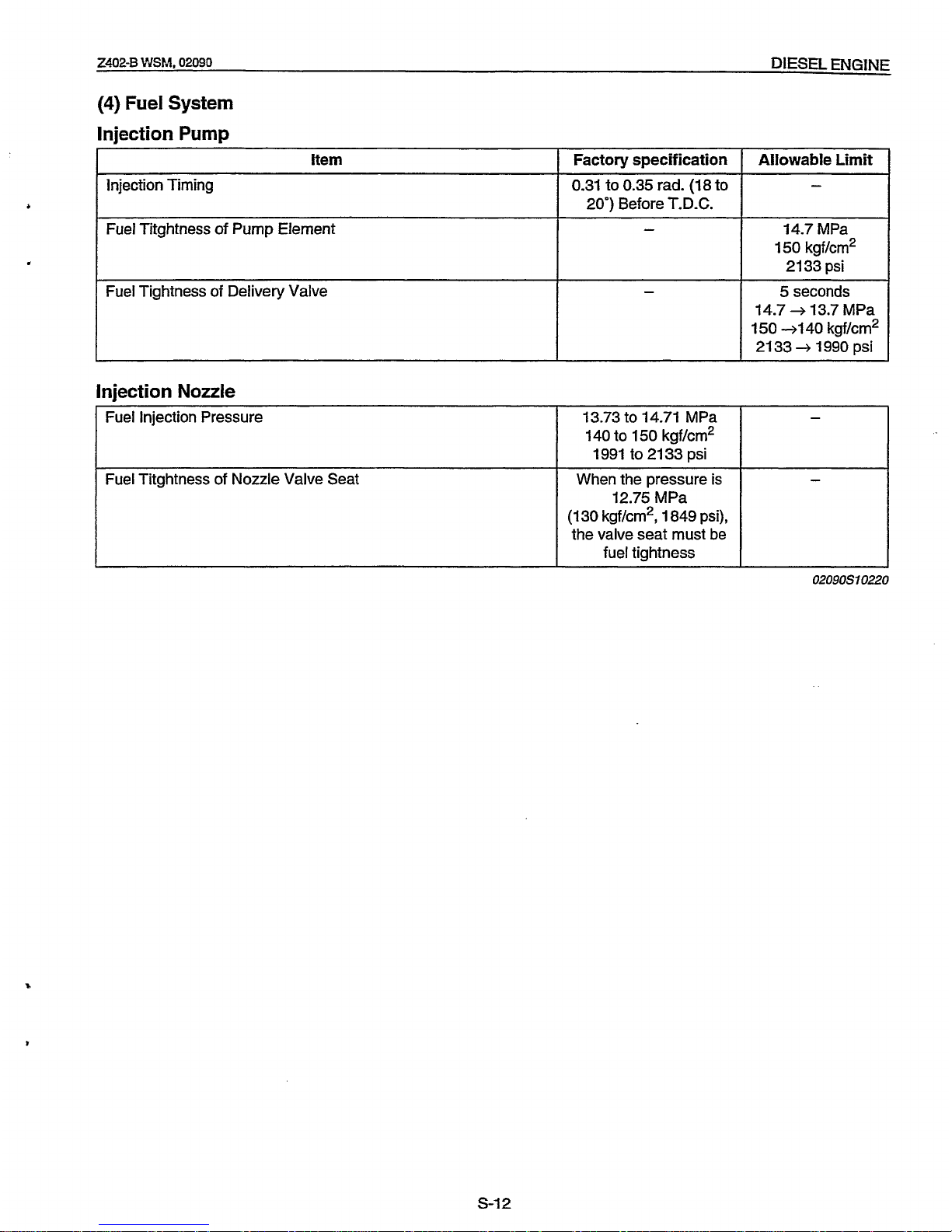
(4)
Fuel
System
Injection
Pump
1
item
13.73 to 14.71 MPa
140 to 150 kgf/cm2
1991 to 2133 psi
12.75 MPa
(1 30 kgf/cm2,
1
849 psi),
the valve seat must be
fuel tightness
When the pressure is
Injection Timing
I
-
-
Fuel Titghtness
of
Pump Element
Fuel Tightness of Delivery Valve
0.31 to 0.35 rad. (18
to
20') Before T.D.C.
Allowable
Limit
14.7 MPa
150 kgf/cm2
21 33 psi
5 seconds
14.7
+
13.7 MPa
150
41
40 kgf/cm2
2133
+
1990
psi
Injection
Nozzle
Fuel Injection Pressure
Fuel Titghtness
of
Nozzle Valve Seat
02090S10220
s-I2
Page 22

DIESEL ENGINE
Z402-B
WSM,
02090
the table below.
Service Interval
50
hrs
100
hrs
200
hrs
400
hrs
800
hrs
1000
hrs one year
two
years
Item Every Every Every Every Every Every Every Every
Checking
fuel
pipes and clamps
*
Changing engine oil
T?
Cleaning air filter element
72
Cleaning
fuel
filter element
*
Checking fan belt tension and damage
Checking water pipes and clamps
*
Changing oil filter element
Changing fuel filter cartridge
*
Checking valve clearance
a
Changing radiator coolant (L.L.C)
k
Changing air filter element
*
Checking nozzle injection pressure
*
Changing water pipes and clamps
Changing
fuel
pipes and clamps
-
*
a2
a
..
*
a
*
Change engine
oil
and oil cartridge after the first
50
hours
of
operation.
S-13
Page 23

2402-B
WSM,
02090
DIESE
ENGINE
171
CHECK
AND
MAINTENANCE
(1)
Daily
Check
Points
Checking Engine Oil Level
1.
Level the engine.
2.
To
check the oil level, draw out the dipstick, wipe
it
clean,
reinsert
it,
and draw
it
out again.
Check to see that the oil level lies between the
two
notches.
3.
If
the level
is
too low, add new oil to the specified level.
0
When using an oil of
different
maker or viscosity from the
previous one, drain old oil. Never mix
two
different types of
oil.
IMPORTANT
01640S10050
Checking and Replenish Cooling Water
1.
Remove the radiator cap and check
to
see that the cooling water
2.
If
low, add clean water and antifreeze.
A
CAUTION
Do
not remove the radiator cap until cooling water
temperature is below its boiling point. Then loosen the cap
slightly to relieve any excess pressure before removing the
cap completely.
0
Be sure to close the radiator cap securely. If the cap is
loose or improperly closed, water may leak out and
the
engine could overheat.
Do
not use an antifreeze and scale inhibitor at the same
time.
level is
just
bellow the port.
IMPORTANT
01
64051
0060
s-I
4
Page 24

DIESEL ENGINE
24024
WSM,
02090
(2)
Check
Point
of
Every
50
Hours
I
01
640F10270
I
P
Checking Fuel Pipe
1.
If
the clamp
(1)
is loose, apply oil to the threads and securely
retighten it.
2.
The fuel pipe
(2)
is
made of rubber and ages regardless of the
period
of
service.
Change the fuel pipe together with the clamp every
two
years.
3.
However,
if
the fuel pipe and clamp are found to be damaged or
deteriorate earlier than two years, then change or remedy.
4.
After the fuel pipe and the clamp have been changed, bleed the
fuel system.
A
CAUTION
Stop the engine when attempting the check and change
(1)
Clamp
(2)
Fuel Pipe
prescribed above.
01640S10070
(When bleeding fuel system)
4
'?.
1.
Fill the fuel tank with fuel, and open the fuel cock
(1).
2.
Loosen the air vent plug
(2)
of the fuel filter a few turns.
3.
Screw back
the
plug when bubbles do not come up any more.
4.
Open the air vent cock on top of the fuel injection pump.
5.
Retighten the plug when bubbles do not come up any more.
NOTE
Always keep the air vent
plug
on the fuel injection pump
closed except when air is vented,
or
it may cause the engine
to
stop.
(1)
FuelCock
(2)
Air
Vent
Plug
0
1640s
IO080
S-15
Page 25

Z402-8
WShl,
02090
DIESEL
ENGINE
(3)
Check
Points
of
Every
100
Hours
Model
2402-8
IOOOOF10621
Capacity
1.9
L
1.7
IrnD.ats.
2.0
u.s.qts.
lOOOOF10641
OOOOOF10631
Changing Engine OiI
1.
After warming up, stop €he engine.
2.
To
change the used
oil,
remove the drain plug at the bottom of
3.
Reinstall the drain plug.
4.
Fill the new oil up to the upper notch on the dipstick.
0
Engine
oil
should
be
MIL-L-46152 / MIL-L-2104C
or
have
0
Change the type of engine according to the ambient
the engine and drain
off
the oil completely.
IMPORTANT
properties
of
API
classification
CD / CE
grades.
temperature.
.
0
'C
to
25
'C
(32
"F
to
77
OF)
......
SAE 20
or
1
OW-30
Below 0 'C
(32
'F).......................SAE
1OW or 1OW-30
Above
25
"C
(77
OF)
....................
SAE 30
or
1OW-30
02090510230
Checking Fan Belt Tension
1.
Press the fan belt between fan pulley and pulley at force of 98
N
(10
kgf, 22 Ibs).
Check
if
the fan belt deflection is
10
to 12 mm (0.394 to 0.472 in.).
2.
If
the deflection is not within the factory specifications, adjust
with the tension pulley adjusting bolts.
(A)
Good
(B)
Bad
01640510170
Fan Belt Damage and Wear
1.
Check the fan belt for damage.
2. Check
if
the fan belt is worn and sunk in the pulley groove.
3.
Replace the fan belt
if
the belt is damaged or nearly worn out
and deeply sunk in the pulley groove.
00000510462
S-1
6
Page 26

DIESEL ENGINE
240243
WSM,
02090
131640F10280
Cleaning Fuel Filter
1.
Close the fuel filter cock
(3).
2.
Unscrew the retaining ring
(6)
and remove the cup
(5),
and rinse
the inside with kerosene.
3.
Take out the element
(4)
and dip it in the kerosene to rinse.
4.
After cleaning, reassemble the fuel filter, keeping out dust and
dirt.
5.
Bleed the fuel system.
IMPORTANT
If dust and
dirt
enter the fuel, the fuel injection pump and
injection nozzle
will
wear quickly.
To
prevent this, be sure
to clean the fuel filter cup periodically.
(1)
CockBody
(4)
Filter Element
(2)
Air
Vent
Plug
(3)
Filter
Cock
(6) Retaining Ring
(5)
Filter
Cup
01640S10120
Cleaning Air Cleaner
1.
The air cleaner uses a dry element. Never apply oil to it.
2.
Remove and clean out the dust cup before it becomes half full
with dust.
3.
When the air filter element
is
dusty,
clean it.
NOTE
Change the element once a year or every 6th cleaning.
Cleaning Air Filter Element
When dry
dust
adheres
02090S10050
Use clean dry compressed air on the inside of the element.
Air
pressure
at
the nozzle must
not
exceed
690
kPa
(7
kgf/cm2,
100
psi).
Maintain reasonable distance between the nozzle and the filter.
0209OS10060
f
S-17
Page 27

.
2402-8
LVSM,
02090
DIESEL
ENGINE
(4)
Check
Points
of
Every
200
Hours
v
11 650F10080
Checking Radiator
Hoses
(Water Pipes)
1.
Check to see if the water pipes
are
properly fixed every
200
hours
of
operation or every six months.
2.
If
clamp bands are loose or water leaks, tighten bands securely.
Replace hoses and tighten clamp bands securely, if radiator
hoses are swollen, hardened or cracked.
3.
Replace hoses and clamp bands every 2 years or earlier
if
checked and found that hoses are swollen, hardened or cracked.
02090510070
Changing Engine Oil Filter Cartridge
1.
Remove the oil filter cartridge
(1)
with a filter wrench.
2.
Apply engine oil to the rubber gasket on the new cartridge.
3.
Screw the new cartridge in by hand.
H
NOTE
Over-tightening may cause deformation of rubber gasket.
After cartridge has been replaced, engine oil normally
decreases
a
little.
Check the oil level and add new oil to the specified level.
(1)
Oil
Filter
Cartridge
01
650.51
0440
s-18
Page 28

DIESEL
ENGINE
2402-B
WSM,
02090
0.145
to 0.185 mm
Valve clearance Factory spec.
0.0059
to 0.0073
in.
I
Number
of
cylinders
Valve arrangement
Adjustable cylinder
Location
of
piston
(1)
When
No.
1
piston Is at top
Ist
dead center compression 2nd
overlap position 2nd
(1)
When No. 1 piston is at
the
I
ISt
(1)
Punch Mark
(2)
TC
Mark Line
2
cylinder
IN.
Ex
*
*
*
*
(3)
Valve Clearance
01650S10290
S-19
Page 29

2402-B
WSM.
02090
DIESEL
ENGINE
(6)
Check
Points
of
Every
1000
Hours
A
CAUTION
Check the nozzle injection pressure and condition after
confirming that there
is
nobody standing in the direction the
fume
goes.
If
the fume from the nozzle directly contacts the
human body,
cells
may
be
destroyed and blood poisoning
may be caused.
01640S10160
Checking
Nozzle
Injection Pressure
[
OOOOOF10690
I
I
01 640F10500
I
[8]
SPECIAL
TOOLS
@e@
)OOOOFOO170
OOOOOFOO14O
1.
Set the injection nozzle to the nozzle tester (Code
No:
07909-
31
361).
2.
Slowly move the tester handle to measure the pressure at which
fuel begins jetting out from the nozzle.
3.
If
the measurement is not within the factory specifications,
disassemble the injection nozzle, and change adjusting washer
(1)
until the proper injection pressure is obtained. (See page
S-
55.)
4.
If
the spraying condition is defective, replace the nozzle piece.
(Reference)
Pressure variation with
0.025
mm (0.001 in.) difference
of
adjusting washer thickness.
Approx. 59 kPa (6 kgf/cm2,
85
psi)
(1)
Adjusting
Washer
02090S10080
Flvwheel Puller
Code
No:
0791 6-3201
1
Application: Use to remove the flywheel.
01640S10180
Special-use Puller
Set
Code
No:
0791 6-09032
Application: Use for pulling out bearings, gears and other parts.
01640s70190
s-20
Page 30

DIESEL
ENGINE
2402-8
WSM,
02090
00000F00240
Valve Seat Cutter Set
Code
No:
07909-331 02
Application: Use
for
correcting valve seats.
01640S10200
Diesel Engine Compression Tester
Code
No:
07909-30207
Application: Use for measureing diesel engine compression
pressure.
01640s10210
Oil
Pressure Teste;
Code
No:
0791 6-32031
Application: Use for measureing lubricating oil pressure.
)00000F00230
I
01640S10220
Connecting
Rod
Alignment
Tool
Code
No:
07909-31661
Application: Use for checking the connecting rod alignment.
Applicable range: Connecting rod big end
I.D.
30
to
75
mrn
(1.18
to
2.95
in.dia.). Connecting rod length
65
to
330
mm
(2.56
to
12.99
in.).
00000F00250
01640510230
Press Gauge
Application: Use for checking the oil crearance between crankshaft
and bearing, etc.
Measureing: Green
----
0.025
to
0.076
rnm
range
(0.001
to
0.003
in.)
Red
---I---
0.051
to
0.152
mrn
(0.002
to
0.006
in.)
Blue--------
0.1
02
to
0.229
mm
(0.004
to
0.009
in.)
Code
NO:
07909-30241
01640S10240
s-21
Page 31

.
H
I
J
2402-8
YJSM,
02090
DIESEL
ENGINE
5
rnrn
(0.197
in.)
6.0
to
6.1
rnrn
dia. (0.236
to
0.240
in.
dia.)
18
rnrn
dia. (0.71
in.
dia.1
~~
00000F10030
Red Check
(Crack
Check
Liquid)
Code
No:
07909-31371
Application:
Use
for
checking cracks
on
cylinder head, cylinder
block, etc.
NOTE
The following special tools are not provided,
so
make them referring to the figure.
D
I-
-.
“I
cI
)11790F00451
I
G
-
k
J
11790F00461
01640810250
01640510910
Valve Guide Replacing
Tool
Application:
Use
to press out and press fit
the valve guide.
I
A
I
20
rnrn
dia. (0.79
in.
dia.)
9.96
to
9.98
rnrn
dia.
lBl
0.3921
to
0.3929
in.
dia.
5.5
to
5.7
rnrn
dia.
IcI
0.21 65
to
0.2244
in.
dia.
41
15
rnrn
(0.59
in.)
I-
~
.-
K
I
10.6
to
10.7
mrn
dia.
(0.417
to
0.421
in.
dia.
L
I
7
rnrn
(0.276
in.)
C1
I
Chamfer 1
.O
rnrn
(0.039
in.)
I
C2
I
Chamfer 2.0
rnm
10.079
in.)
I
1
C0:3
I
Chamfer
0.3
mrn
(0.012
in.)
I1
790600623
S-22
Page 32

DIESEL ENGINE
2402-6 WSM, 02090
M
N
P
I
8
mrn
(0.31 in.)
4
mm
(0.16 in.)
11.97 to 11.99
mm
dia.
Q
mfl
T
S
R
S
W
17
mm
(0.67
in.)
4
mm
(0.16 in.)
12.00 to 12.02
mm
dia.
1790F00500
I
U
V
Injection
Pump
Pressure Tester
Application: Use to check fuel tightness
of
injection
pumps.
I
A
I
29.4 MPa (300 knf/cm2, 4267 psi)
Pressure gauge
full
scale : More than
(0.4724 to 0.4732 in. dia.)
100
mm
(3.94
in.)
M12xP1.5
I
B
I
Comeraasket
I
C
D
I
Flange (Material : Steel)
I
Hex. nut 27
mm
(1.06 in.) across the plat
E
I
Injection pipe
F
I
PF 112
1
1
5
mm
(0.20 in.)
I
17
mm
dia.
(0.67
in. dia.)
8
mm
dia. (0.31 in.
dia.)
1
.O
mm
(0.039 in.)
17
mm
dia. 10.67 in. dia.)
6.1
0
to
6.20
mm
dia.
1
I
10.2402
to
0.2441
in. diaJ
I
(0.4713 to 0.4721 in.
dia.)
U
P
I
PFW2
I
Q
I
23mm
(0.91
in.)
I
I
a I Adhesive aoolication
I
I
b
I
Fillet welding on the enter circumference
1
1179060081
1
.
S-23
Page 33

B
C
-
c
Z402-B
WSM,
02090
DIESEL
ENGINE
A
B
C
A
-
145
rnrn
(5.71 in.)
20
rnrn
(0.79 in.)
100
rnrn
(3.94 in.)
E
F
a
b
:I:
F
E
11790F00490
19.90
to
19.95
rnrn
(0.7835
to
0.7854 in.)
21 -90
to
21 -95
rnrn
(0.8622
to
0.8642 in.)
DIA.
25
rnrn
(0.98 in.)
6.3
prn
(250 pin.)
6.3
urn
1250 uin.)
A
B
C
150
rnrn
(5.91 in.)
20
rnrn
(0.79 in.)
100
rnrn
13.94 in.)
E
F
a
b
19.90
to
19.95
rnrn
(0.7835
to
0.7854 in.)
21.90
to
21.95
rnrn
(0.8622
to
0.8642 in.)
DIA.
25
rnrn
(0.98 in.)
6.3
prn
(250 pin.)
6.3
urn
(250 uin.1
11900G00442
Flywheel
Stopper
Application: Use
to
loosen and tighten the
flywheel screw.
A
B
C
200
rnrn
(7.87 in.)
30
rnrn
(1.18 in.)
20
rnrn
(0.79 in.)
I
D
I
15
rnrn
10.59 in.)
I
E
F
G
15mrn (0.59 in.)
8
rnrn
(0.31 in.)
10
rnrn
DIA.
(0.39 in.
DIA.)
11
790G00801
S-24
Page 34

DIESEL
ENGINE
2402-B
WSM,
02090
A
B
C
A
-,D
,_
E
130
mm
(5.12 in.)
72
rnrn
(2.83 in.)
1.57
rad.
(40')
Crankshaft Bearing 1 Replacing
Tool
Application:
Use to press
out
and
to
press
fit
the crankshaft bearing
1.
[Press
Out]
E
F
G
,
,
A
B
I
135
mrn
(5.31 in.)
I
72
mrn
(2.83 in.)
24
rnrn
(0.95 in.)
20
mm
dia.
(0.79
in.
dia.)
68
mrn
dia.
(2.68
in.
dia.)
39.90
to
39.95
mm
dia.
I
C
I
1.57
rad.
(40'1
I
1
i
1
10
mrn
(0.39
in.)
1
22
mrn
(0.87 in.)
20
rnrn
(0.79 in.)
48.90
to
48.95
rnm
dia.
(1.9251
to
1.9271
in.
dia.)
43.90
to
43.95
rnrn
dia.
I
11.7283
to
1.7303
in.
dia.)
I
[Press
Fit]
I
D
I
9
mm
10.35
in.)
I
c
I
(1 3709
to
1.5728
in.
dia.)
n
I
1
7900600452
S-25
Page 35

2402-8
VWA,
02090
DIESEL
ENGINE
10
ENGINE
BODY
CHECKING
AND
ADJUSTING
Compression Pressure
1.
After warming up the engine, stop
it
and remove the air cleaner,
the muffler and all nozzle holders.
2.
Install a compression tester (Code
No:
07909-30204)
for diesel
engines to nozzle holder hole.
3.
After making sure that the speed control lever is set at the stop
position (Non-injection), run the engine at
200
to
300
rpm with
the starter.
4.
Read the maximum pressure. Measure the pressure more than
twice.
5.
If
the measurement is below the allowable limit, check the
cylinder, piston ring, top clearance, valve and cylinder head.
6.
If
the measurement is below the allowable limit, apply a small
amount
of
oil to the cylinder wall through the nozzle hole and
measure the compression pressure again.
7.
If
the compression pressure is still less than the allowable limit,
check the top clearance, valve and cylinder head.
8.
If
the compression pressure increases after applying oil, check
the cylinder wall and piston rings.
NOTE
clearance.
Check the compression pressure with the specified valve
Always use a fully charged battery for performing this test.
Variances in cylinder compression values should be under
10
Yo.
Factory spec.
29
to
33
kgf/cm2
2.26
MPa
327
psi
Compression pressure
Allowable limit
23
kgf/cm2
02090510090
S-26
Page 36

DIESEL
ENGINE
2402-8
WSM,
02090
(3
@
=
OOOOOF10510
OOOOOF10520
Top Clearance
1.
Remove the cylinder head (remove the cylinder head gasket
completely).
2.
Bring the piston to its top dead center fasten
1.5
mm dia. 5 to
7
mm long fuse wires to 3 to 4 spots on the piston top with grease
so
as to avoid the intake and exhaust valves and the combustion
chamber ports.
3.
Bring the piston to its middle position, install the cylinder head,
and tighten the cylinder head bolts to specification. (Head
gasket must be changed to new one.)
4.
Turn the crank shaft until the piston exceeds its top dead center.
5.
Remove the cylinder head, and measure squeezed fuse wires
for thickness.
6.
If
the measurement is not within the specified value, check the oil
clearance
of
the crankpin journal and the piston pin.
0.50
to
0.70
mm
0.0197
to
0.0276
in.
37.2
to
42.1
Nam
Factory spec.
Top
clearance
Cylinder head mounting
to
4.3
kgf.m
lightening torque
bolts
27.5
to
31.1
ft-lbs
(1)
Fuse
Draining Cooling Water and Engine
Oil
A
CAUTION
Never remove radiator cap until cooling water temperature
is
below its boiling point.
Then loosen cap slightly to the
stop to relieve any excess pressure before removing cap
completely.
1.
Prepare a bucket. Open the drain cock to drain cooling water.
2.
Prepare an oil pan. Remove the drain plug to drain engine oil in
the pan.
01640S10290
121
EXTERNAL COMPONENTS
Air Cleaner and Muffler
1.
Remove the air cleaner.
2.
Remove muffler retaining nuts to remove the muffler.
(When reassembling)
Install the muffler gasket
so
that its steel side face the muffler.
Alternator and Fan Belt
1.
Remove the alternator.
2.
Remove the fan belt.
(When reassembling)
Check
to
see that there are no cracks on the belt surface.
IMPORTANT
After reassembling the fan belt, be sure to adjust the fan
belt tension.
02090s10100
01640S10300
S-27
Page 37

24024
VJSM,
02090
DIESEL
ENGINE
[3I
CYLINDER HEAD AND VALVES
NonIe Holder Assembly
1
Loosen the screws on the pipe clamps.
2.
Remove the injection pipes.
3.
Remove the fuel overflow pipes.
4.
Loosen the lock nuts, and remove the nozzle holder assemblies.
5.
Remove the copper gaskets on the seats.
(1)
Nozzle Holder Assembly
01640510321
Cylinder Head Cover
1.
Remove the head cover cap nuts.
2.
Remove the cylinder head cover
(1).
(When reassembling)
0
Check to see
if
the cylinder head cover gasket is not defective.
(1)
Head Cover
01640S10331
Rocker Arm and Push Rod
1.
Remove the rocker arm bracket mounting nuts.
2.
Detach the rocker arm
as
a unit.
3.
Remove the push rods.
H
IMPORTANT
0
After reassembling the rocker arm, be sure to adjust the
valve clearance.
(When reassembling)
0
When putting the push rods onto the tappets, check to see
if
their ends are properly engaged with the grooves.
(1)
Rocker
Arm Assembly
(2)
PushRod
Cylinder Head
1.
Loosen the pipe band, and remove the water return pipe.
2.
Remove the cylinder head screws in the order of
(IO)
to
(I),
and
3.
Remove the cylinder head gasket and O-ring.
(When reassembling)
Replace the head gasket with a new one.
0
Install the cylinder head, using care not to damage the O-ring.
0
Tighten the cylinder head screwsgradually in the order
of
(1)
to
(1
0)
after applying engine oil.
Retighten the cylinder head screws after running the engine for
30
minutes.
(A) Gear Case Side
11900810062
remove the cylinder head.
(B)
Flywheel Side
11900S10073
S-28
Page 38

DIESEL ENGINE
2402-8
WSM,
02090
01650P10090
Tappets
1.
Remove the tappets
(1)
from the crankcase.
(When reassembling)
Before installing the tappets, apply engine oil thinly around them.
Mark the cylinder number to
the
tappets to prevent
(1)
Tappet
IMPORTANT
interchanging.
11900S10082
Valves
1.
Remove the valve cap
(1).
2.
Remove the valve spring collet
(2)
with a valve lifter.
3.
Remove the valve spring retainer
(3),
valve spring
(4)
and valve
(When reassembling)
Wash the valve stem and valve guide hole, and apply engine oil
After installing the valve spring collets, lightly tap the stem to
(1)
Valve Cap
(2)
Valve Spring Collet
(3)
Valve Spring Retainer
(5).
c
sufficiently
assure proper fit
with
a
plastic hammer.
(4)
Valve Spring
(5)
Valve
11900510092
S-29
Page 39

t
Tightening torque
2402-8
VJSi.n,
02080
DlESEL
ENGINE
9.81 to
11
-3 Nm
screw
Injection
and
pump
nut
retaining
.oo
to
.1
kgf.m
7.23 to 7.32
ft-lbS
141
TIMING GEAR AND CAMSHAFT
Tightening torque
01 650P10130
I
Ill
117.6 to 127.4 Nm
12.0
to
13.0 kgfm Crankshaft screw
86.4 to 93.6
ft-lbs
Injection Pump and Speed
Control
Plate
1.
Remove the socket head screws and nuts, and remove the
2.
Remove the screws and separate the speed control plate
(2),
3.
Disconnect the spring
(4)
and remove the speed control plate
(When reassembling)
0
Hook the spring
(4)
to the lever
(5)
first and install the speed
control plate
(2).
0
Be sure to place the copper washers underneath
two
screws
(1).
Position the slot
(9)
on the fork lever just under the slot
(8)
on the
crankcase.
0
Insert the injection pump
so
that the control rod
(7)
should be
pushed by the spring
(6)
at its end and the pin
(10)
on the rod
engages with the slot
(9)
on the fork lever.
injection pump
(3).
taking care not to damage the spring
(4).
(2)
-
W
NOTE
0
The sealant is applied to both sides
of
the
soft
metal gasket
shim. The liquid gasket is not required for assembling.
0
Addition or reduction
of
shim
(0.05
mm,
0.0020
in.) delays or
advances the injection timing by approx.
0.0087
rad
(0.5").
0
In
disassembling and replacing, be sure to use the same
020905101
10
5-30
Page 40

DIESEL ENGINE
2402-8
WSM,
02090
--%mdr
15020F1
’f
01
650F10090
02090F10090
Gear Case
1.
Unscrew the screw
(2)
and disconnect the start spring
(1)
in the
2.
Remove the gear case.
(When reassembling)
Apply a liquid gasket (Three Bond
1215
or equivalent) to both
Grease thinly to the oil seal, and install it, ensuring the lip does
speed control plate mounting hole.
sides of the gear case gasket.
not
come off.
(1)
Start Spring
(2)
Screw
Idle Gear
01650510320
1.
Remove the external snap ring
(I),
the collar
(2)
and the idle
(When reassembling)
Install the idle gear, aligning the mark
on
the gears referring to
gear
(3).
the figure.
(1)
External Snap Ring
(2)
Idle Gear Collar
(3)
Idle Gear
01650510330
Fuel Camshaft
1.
Remove the screws and draw out the camshaft with the gear on
2.
Remove the retaining plate
(1).
3.
Remove the screws, then draw
out
the injection pump gear
(2)
(When reassembling)
Hook the spring to the fork lever
2
(4)
as shown in the figure
it.
and fuel camshaft
(3)
with the governor fork assembly.
before installing the fork lever assembly to the crankcase.
(1)
Retaining Plate
(2)
Injection Pump Gear
(3)
Fuel Camshaft
(4)
Fork Lever
2
(5)
Fork Lever
1
(6)
Governor Sleeve
02090510200
Oil
Pump and Crankshaft Gear
1.
Unscrew the flange nut
(7)
and remove the oil pump gear
(6).
2.
Unscrew the retaining screws and remove the oil pump
(5).
3.
Remove the collar
(I),
O-ring
(2)
and oil slinger
(3).
4.
Remove the crankshaft gear
(4)
with a puller.
(When reassembling)
0
Install the collar after aligning the marks on the gears. (See the
figure at “Idle Gear”.)
(1)
Crankshaft Collar
(2) O-ring
(3)
Crankshaft Oil Stinger
(4)
Crankshaft Gear
(5)
Oil Pump
(6)
Oil
Pump Gear
(7)
Flange
Nut
01650510350
+
S-31
Page 41

t
Tightening toque
t
26.5
to
30.4
N.m
2.7
to
3.1
kgfm
Connecting rod screw
19.5
to 22.4
ft-lbs
2402-B
WSM,
02090
DIESEL
ENGINE
151
PISTON
AND
CONNECTlNG
ROD
11
650F10100
uzl
01
650F10110
01650F10120
Oil Pan and
Oil
Strainer
1.
Unscrewthe oil pan mounting screws
(5),
and remove the oil pan
2.
Unscrew the oil strainer mounting screw
(4),
and remove the oil
(3)-
strainer
(2).
(When reassembling)
Install the oil strainer, using care not
to
damage the O-ring
(1).
Using the hole
(6)
numbered
“2”,
install the oil strainer by
mounting screw.
Apply liquid gasket (Three Bond 1270D or 1270C) to the oil pan
as shown in the figure.
IMPORTANT
Scape
off
the oil adhesive completely. Wipe the’sealing
surface clean using waste cloth soaked with gasoline. Now
apply new adhesive
3
-
5
mm thick all over the contact
surface. Apply the adhesive also on the center
of
the flange
as well as on the inner wall of each bolt hole.
Cut the nozzle of the “fluid sealang” container at its second
notch. Apply “fluid sealant” about
5
mm thick.
Within
20
minutes after the application
of
fluid sealant,
reassemble the components. Wait then for about
30
minutes, and pour
oil
in
the crankcase.
(1)
O-ring
(2)
Oil Strainer
(3)
Oil Pan
(4) Screw
(5)
Oil Pan Mounting Screws
(6)
Hole
11900510192
5-32
Page 42

DIESEL ENGINE
2402-8
WSM,
02090
I
J1650F10130
Piston
1.
Turn the flywheel and bring the No. 1 piston to the top dead
2.
Pull
out the piston upward by lightly tapping it from the bottom
of
(When reassembling)
Before inserting the piston into the cylinder, apply enough engine
oil to the cylinder.
When inserting the piston into the cylinder, face the mark on the
connecting rod to the injection pump.
center.
the crankcase with the grip
of
a hammer.
IMPORTANT
Do
not change
the
combination of cylinder and piston.
Make sure of the position of each piston by marking. For
example, mark
“1”
on
the
No.1
piston.
e
When inserting
the
piston into the cylinder, place the gap of
the compression ring
1
on the opposite side of the
combustion chamber and stagger the gaps of the
compression ring
2
and oil
ring
making a right angle from
the
gap of the compression
ring
1.
Carefully insert the pistons using a piston ring compressor.
Otherwise, their chrome-plated section may be scratched,
causing trouble inside
the
liner.
!.*
(A)
Top
Ring
Gap
(B)
Second Ring
Gap
(C)
Oil Ring
Gap
(D)
Piston Pin Hole
11900510202
t
s-33
Page 43

Z4.02-B
WSh4,02090
DIESEL
ENGINE
.
I1
900F10400
I
1900F10410
/"
P
/
/
11790F10500
I11790F10510
Piston Ring
and
Connecting
Rod
1.
Remove the piston rings using a piston
ring
tool.
2.
Put the casting mark
3.
Remove the piston pin
(l),
and separate the connecting rod
(7)
from the piston
(2).
(When reassembling)
When installing the ring, assemble the rings
so
that the
manufacturer's mark
(12)
near the gap faces the top of the-
piston.
When installing the oil ring onto the piston, place the expander
joint
(IO)
on the opposite side
of
the oil ring gap
(1
1).
Apply engine oil
to
the piston pin.
When installing the piston pin, immerse the piston in
80
"C
(176
OF)
oil for
10
to
15
minutes and insert the piston pin to the piston.
When installing the connecting
rod
to the piston, align the mark
(9)
on the connecting rod to the casting mark
(8).
W
IMPORTANT
Mark the same number on the connecting
rod
and the
(1) Piston Pin
(2) Piston
(8)
Casting Mark
(3)
Piston Pin Snap Ring
(4)
Compression Ring
1
(5) Compression Ring 2
(6)
Oil Ring
(8)
on the piston as shown
in
figure.
piston
so
as
not to change the combination.
(7) Connecting Rod
(9)
Mark
(10)
Expander Joint
(1
1) Oil Ring Gap
(12) Manufacturer's Mark
11900S10211
s-34
Page 44

DIESEL ENGINE
2402-8 WSM,
02090
[6]
FLYWHEEL
AND CRANKSHAFT
Starter
1.
Remove the starter.
02090S10240
Flywheel
1.
Lock the flywheel not to turn using the flywheel stopper.
2.
Remove the flywheel screws, except for two which must be
3. Set a flywheel puller (Code
No:
07916-32011), and remove the
(When reassembling)
Apply engine
oil
to the flywheel screws.
loosened and left as they are.
flywheel.
01640s10400
Bearing Case Cover and Crankshaft
NOTE
Before disassembling, check the side clearance
of
crankshaft. Also check it during reassembly.
1.
Remove the bearing case cover mounting screws.
2.
Remove the bearing case cover.
3. Remove the bearing case screw
2
(5).
4.
Pull
out the crankshaft.
(When reassembling)
IMPORTANT
Install the crankshaft sub assembly, aligning the screw hole
of
main bearing case
2
(2)
with the screw hole of cylinder
block
(1).
Apply engine oil to
the
seat and thread of bearing case
screw
2
(5)
and tightening it.
Install the bearing case cover
(3)
to position the casting
mark
"T'
(4)
on
it
upward.
Tighten the bearing case cover mounting screws with even
force on the diagonal
line.
(I)
Cylinder Block
(2) Main Bearing Case
2
(5)
Bearing Case Screw 2
(3)
Bearing Case Cover
(4)
Top
Mark
'I?'
01650510370
,
s-35
Page 45

Zm-8
WSM,
02090
DIESEL
ENGINE
~~
SERVICING
[I]
CYLINDER HEAD
01650F10150
I
I
OOOOOF1OOZO
Main Bearing Case Assembly
1.
Remove the
tv~o
main bearing case screws
I,
and remove
the
main bearing case assembly
1
(2),
being careful crankshaft
bearing
2.
2.
Remove the main bearing case assemblies
(1).
(When reassembling)
Clean the oil passage
in
the main bearing case.
Apply clean engine oil on the crankshaft bearing 2 and main
When installing the main bearing case assemblies
1,
face the
(1)
Main Bearing
Case
Assembly
bearing case assembly
1.
mark
“FLYWHEEL”
to
the flywheel.
(2)
Main Bearing Case
Assembly
1
01
650S10380
Cylinder Head Surface Flatness
1.
Thoroughly clean the cylinder head surface.
2.
Place a straightedge on the cylinder head’s four sides and two
diagonal as shown in the figure.
Measure the clearance with a feeler gauge.
surface grinder.
3.
If
the measurement exceeds the allowable limit, correct it with a
IMPORTANT
Do
not place the straight edge on the combustion chamber.
Be sure to check the valve recessing after correcting.
OOOOOS
100
12
S-36
Page 46

DIESEL
ENGINE
00000F10030
~00000F10050
I
2402-8
WSM,
02090
Cylinder Head Flaw
1.
Prepare an air spray red check (Code
No.
07909-31371).
2.
Clean the surface
of
the cylinder head
with
detergent
(2).
3.
Spray the cylinder head surface
with
the red permeative
liquid
4.
Wash away the red permeative
liquid
on the cylinder head
5.
Spray
the
cylinder head surface
with
white developer
(3).
6.
If
flawed,
it
can be identified as red marks.
(1)
Red Permeative Liquid
(3)
White Developer
(2)
Detergent
Valve Recessing
1.
Clean
the
cylinder head,
the
valve face and seat.
2.
Insert
the
valve into the valve guide.
3.
Measure the valve recessing
with
a depth gauge.
4.
If
the measurement exceeds
the
allowable
limit,
replace the
valve.
If
it
still
exceeds the allowable
limit
after replacing the valve,
correct
the
valve seat face of the cylinder head
with
a valve seat
cutter (Code
No.
07909-331
02)
or valve seat grinder.
Then, correct the cylinder head surface
with
a surface grinder,
or
replace the cylinder head.
(1).
Leave
it
five
to
ten
minutes
after spraying.
surface
with
the detergent
(2).
00000s10020
OOOOOS10032
Clearance between Valve Stem and Valve Guide
1.
Remove carbon
from
the valve guide section.
2.
Measure
the
valve stem
O.D.
with
an outside micrometer.
3.
Measure
the
valve guide
I.D.
of
the
cylinder head at the most
wear pari as
shown
in
the
figure below
with
a small hole gauge.
And
calculate the clearance.
4.
If
the clearance exceeds the allowable
limit,
replace the valves.
If
it
still
exceeds the allowable
limit,
replace the valve guide.
00000510042
.
s-37
Page 47

2402-B
k~~S~I,U2090
DIESEL ENGINE
Valve face angle
Valve Seating
I,
Coat the valve face lightly
with
Prussian blue and put the valve
on
its
seat to check the contact.
2.
If the valve does not seat all the way around the valve seat or the
valve contact is
less
than
70
%,
correct the valve seating as
follows.
3.
If
the valve contact does not comply with the reference value,
replace the valve or correct the contact
of
valve seating.
(1)
Correct
(3)
Incorrect
(2)
Incorrect
11
790F10450
0.79 rad.
45.0'
Factory spec.
0
0
0
11
790F10460
~00000F10090
I
7-
I
0.26
rad.
(1
5')
0.79
rad.
(45')
I
A
B
I
C
I
11790S10230
Correcting Valve and Valve Seat
NOTE
Before correcting the valve and seat, check the valve stem
and the
I.D.
of the valve guide section, and repair them
if
necessary.
After correcting the valve seat,
be
sure to check the valve
recessing.
1)
Correcting Valve
1.
Correct the valve with a valve refacer.
I
0.79 rad.
I
Valveseatangle
I
Factoryspec.
I
(a)
Identical Dimensions
(b) Valve
Seat
Width
(A)
Check Contact
(B)
Correct Seat Width
(C)
Check Contact
0165OS10390
5-38
Page 48

DIESEL ENGINE
Z402-B
WSM,
02090
Valve Lapping
1.
Apply compound evenly to the valve lapping surface.
2.
Insert the valve into the valve guide. Lap the valve onto its seat
3.
After lapping the valve, wash the compound away and apply oil,
4.
Apply Prussian blue to the contact surface to check the seated
I
IMPORTANT
When valve lapping is performed, be sure to check the valve
recessing and adjust the valve clearance after assembling
with a valve flapper or screwdriver.
then repeat valve lapping with
oil.
rate,
If
it is less than
70
%,
repeat valve lapping again.
[00000F10120
L
OOOOOFl
01
30
the valve.
00000S70060
Replacing Valve Guide
(When removing)
1.
Using a valve guide replacing tool (see page
5-22),
press out the
(When installing)
1.
Clean a new valve guide, and apply engine oil to it.
2.
Using a valve guide replacing tool, press
in
a new valve guide
until it is flush with the cylinder head as shown in the figure.
3.
Ream precisely the
I.D.
of the valve guide to the specified
dimension.
I
IMPORTANT
0
Do
not hit the valve guide with a hammer, etc. during
replacement.
(A)
When Removing
used valve guide.
(6)
When Installing
02090S70720
Free Length and Tilt
of
Valve Spring
1.
Measure the free length
(A)
with vernier calipers.
If
the
measurement is less than the allowable limit, replace
it.
2.
Put the spring on a surface plate, place a square
on
the side
of
the spring, and check to see
if
the entire side
is
in
contact with
the square. Rotate the spring and measure the maximum
(B).
If
the measurement exceeds the allowable limit, replace.
3.
Check the entire surface
of
the spring for scratches. Replac it,
if
any.
OOOOOS10082
Valve Spring Setting
Load
1.
Place the valve spring
on
a tester and compress it to the same
2.
Read the compression load on the gauge.
3.
If
the measurement is less than the allowable limit, replace it.
length it is actually compressed
in
the engine.
00000S70092
.
s-39
Page 49

2402-B
WSM.
02090
DIESEL
ENGINE
1dOOOOF10140
IOOOOOF10150
Oil
Clearance between Rocker
Arm
Shaft
and
Beraing
I.
Measure the rocker arm beating
I.D.
tyith
an
inside micrometer.
2.
Measure the rocker arm shaft
O.D.
with an outside micrometer,
and then calculate the
oil
Clearance.
3.
If
the clearance exceeds the allowable limit, replace the rocker
arm and measure the oil clearance again.
If
it still exceeds the
allowable limit, replace also the rocker arm shaft.
00000s10102
Push
Rod Alignment
1.
Check the both end
of
the push rod for cracks, damage and
2.
Measure the bending of the push rod with a dial indicator.
3.
If
the measurement exceeds the allowable limit, replace the push
unusual wear.
rod.
00000s10111
Oil
Clearance between Tappet and Tappet Guide Bore
1.
Measure the tappet
O.D.
with an outside micrometer
2.
Measure the
I.D.
of
the tappet guide bore with a cylinder gauge,
3.
If
the oil clearance exceeds the allowable limit
or
the tappet is
and calculate the oil clearance.
damaged, replace the tappet.
[2]
TIMING GEAR AND CAMSHAFT
OOOOOS10123
Timing Gear Backlash
1.
Set a dial indicator (lever type) with its tip on the gear tooth.
2.
Move the gear to measure the backlash, holding its mating gear.
3.
If
the backlash exceeds the allowable limit, check the oil
4.
If
the oil clearance is proper, replace the gear.
clearance
of
the shafts and the gear.
02090S10130
5-40
Page 50

DIESEL
ENGINE
2402-6
WSM.
02090
I " I
"Y".
a",
YY
OOOOOF10251
I02090F10030
I1
640F10531
OOOOOFI
01
90
Idle Gear
Side
Clearance
1.
Set a dial indicator with its tip on the idle gear.
2.
Measure the side clearance by moving the idle gear to the front
3.
If
the measurement exceeds the allowable limit, replace the idle
and rear.
gear collar.
00000510143
Camshaft Side Clearance
1
Set a dial indicator with its tip on the camshaft.
2.
Measure the side clearance by moving the cam gear to the front
3.
If
the measurement exceeds the allowable limit, replace the
and rear.
camshaft stopper.
f
OOOOOS10183
Cam Height
1.
Measure the height
of
the cam at its highest point with an outside
2.
If
the measurement
is
less
than the allowable limit, replace the
micrometer.
camshaft.
OOOOOS10203
Oil Clearance
of
Camshaft Journal
1.
Measure the camshaft journal
O.D.
with an outside micrometer
2.
Measure the cylinder block bore
I.D.
for camshaft with an inside
3.
If
the clearance exceeds the allowable limit, replace the
micrometer.
Calculate the oil clearance.
camshaft.
02090S10140
Oil Clearance between Idle Gear Shaft and Idle Gear Bushing
1.
Measure the idle gear shaft
O.D.
with an outside micrometer.
2.
Measure the idle gear bushings
1.D.
with an inside micrometer,
3,
If
the oil clearance exceeds the allowable limit, replace the
and calculate the oil clearance,
bushing.
00000510152
S-41
Page 51

*
DIESEL
ENGINE
2402-8
WSF.4.02090
1
Replacing Idle Gear Bushing
(A)
(When removing)
1.
Using
an
idle gear bushing replacing
tool
(see page
S-24),
press
out
the
used bushing.
(B) (When installing)
1.
Clean a new idle gear bushing and idle gear bore, and apply
engine oil
to
them.
2.
Using an idle gear bushing replacing tool, press
in
a new
bushing (service parts)
to
the specified dimension. (See figure.)
02090510150
[3]
PISTON
AND
CONNECTING
ROD
OOOOOF10260
000
Piston Pin Bore
I.D.
1.
Measure the piston pin bore
I.D.
in both the horizontal and
2.
If
the measurement exceeds the allowable limit, replace the
vertical directions with a cylinder gauge.
piston.
00000510212
Oil Clearance between Piston Pin and
Small
End Bushing
1.
Measure the
O.D.
of the piston pin where it contacts the bushing
2.
Measure the I.D. of the piston pin bushing at the connecting rod
with an outside micrometer.
small end with a cylilnder gauge.
Calculate the oil clearance.
If
it still exceeds the allowable limit, replace the piston pin.
3.
If
the clearance exceeds the allowable limit, replace the bushing.
00000510222
c
Page 52

DIESEL ENGINE
2402-8
WSM,
02090
..
~0000Fl0280
IOOOOF10740
I
Replacing Small End Bushing
(When removing)
1.
Press out the used bushing using a small end bushing replacing
(When installing)
1.
Clean a new small end bushing and bore, and apply engine oil to
them.
2.
Insert a new bushing onto the tool and press-fit it with a press
so
that the seam
(1)
of
bushing positions as shown in the figure,
until it is flash with the connecting rod.
3.
Drill a hole to the bushing with aligning the oil hole
(2)
of
connecting rod using
3.5
mm
dia.
(0.1
38
in.
dia.) drill.
4
NOTE
Be sure
to
chamfer the
oil
hole circumference with an oil
stone.
(1)
Seam
(A)
When Removing
(2)
Oil
Hole
tool.
(B)
When Installing
00000S10232
Piston
Ring
Gap
1.
Insert the piston ring into the lower part of the liner (the least
2.
Measure the ring gap with a feeler gauge.
3.
If
the gap exceeds the allowable limit, replace the piston ring.
worn
out part) with the piston.
02090S10160
s-43
Page 53

DIESEL
ENGINE
2402-8
WSM,
02090
00000F10300
b
Clearance between Piston Ring
and
Groove
1.
Remove carbon
from
the ring grooves.
2.
Measure the clearance between
the
ring
and the groove
with
a
3.
If
the clearance exceeds allowable limit, replace the ring since
4.
If
the clearance still exceeds the allowable limit after replacing
feeler gauge or depth gauge.
compression leak and oil shortage result.
the ring, replace the piston.
1
Factory spec
:
A
I
More
than
0.079
Oa2
mm
in.
(A)
Top
Ring
(Key
Stone
Type)
(B)
2nd, Oil Ring
00000510252
Connecting Rod Alignment
NOTE
Since the
I.D.
of
the connecting rod small end bushing
is
the
basis
of
this check, check the bushing
for
wear beforehand.
1.
Remove the crankpin bearing, and install the connecting rod
cap.
-
2.
Install the piston pin in the connecting rod.
3.
Install the connecting rod on the connecting rod alignment tool
(Code
No.
07909-31661).
4.
Put a gauge over the piston pin, and move it against the face
plate.
5.
If
the gauge does not fit squarely against the face plate, measure
the space between the pin
of
the gauge and the face plate.
6.
If
the measurement exceeds the allowable limit, replace the
connecting rod.
00000510261
.
Page 54

DIESEL
ENGINE
[4]
CRANKSHAFT
Oversize
Oe2
mm
0.008
in.
0
2'-
Bearing Code Number Marking
Main bearing case assembly 02 15821-07201 020
OS
I
0.2 mm
Oversize
0.008
in.
2402-5 WSM, 02090
0.4
mm
0.01
6
in.
Crankshaft Side Clearance
1.
Set a dial indicator with its tip on the end of the crankshaft.
2.
Measure the side clearance by moving the crankshaft to the front
and rear.
3.
If
the measurement exceeds the allowable limit, replace the main
bearing case assembly.
4.
If
the same size bearing is useless because
of
the crankshaft
journal wear, replace it with an oversize one referring to the table
and figure.
0.15 to
0.25
mm
0.0059 to
0.0098
in.
0.0197 in.
Factory spec.
Allowable limit
Crankshaft side
clearance
(Reference)
0
Oversize main bearing case assembly
I
I
I
Mainbearingcaseassembly
041
15821-07211
I
0400s
I
-. . . - . .
.
1
I
I
Oversize dimensions of crankshaft journal
23.40 to 23.45
mm
23.80
to
23.85
mm
0.071
to
0.087 in. radius
I
The
crankshaft journal must be fine-finished
to
higher than
P8-V
VV
.
I
0
1650s
10400
Crankshaft Alignment
1.
Support the crankshaft with V blocks on the surface plate and set
a dial indicator with its tip on the intermediate journal at right
angle.
2.
Rotate the crankshaft on the V blocks and get the misalignment
(half of the measurement).
3.
If
the misalignment exceeds the allowable limit, replace the
crankshaft.
000005
10282
5-45
Page 55

2402-6
WSM,
02090
DlESEL
ENGINE
Crankpin bearing
I.D.
A
33.995
to
34.010
mm
1.33839
to
1.33898
in.
Factory spec.
Oil Clearance between Crankpin
and
Crankpin Bearing
1.
Clean
the
crankpin and crankpin bearing.
2.
Put
a strip
of
plastigage (Code
No.
07909-30241)
on the center
of the crankpin.
3.
Install the connecting
rod
cap and tighten the connecting rod
screws to the specified torque, and remove the cap again.
4.
Measure the amount of the flattening
MiN7
the scale, and get the
oil clearance.
5.
If the oil clearance exceeds the allowable limit, replace the
crankpin bearing.
6.
If
the same size bearing is useless because
of
the crankpin
wear, replace
it
with an undersize one referring to the table and
figure.
H
NOTE
Never insert the plastigage into the crankpin
oil
hole.
Be
sure not to move the crankshaft while the connecting
rod screws are tightened.
2.3
to
2.7
mm
radius
0.091
to
0.106
in.
radius
A
0.019
to
0.081
mm
0.00075
to
0.00319
in.
Oil
clearance
between
crankpin and crankpin
bearing
Allowable limit
0.0059
in.
2.3
to
2.7
mm
radius
0.091
to
0.106
in. radius
I
Crankpin O.D.
4
mm
radius
0.1
6
in.
radius
33.759
to
33.775
mm
1.32910
to
1.32973
in.
B
C
I
33.959
to
33.975
mm
I
1.33679
to
1.33760
in.
Factory spec.
I
4
mm
radius
0.16
in.
radius
33.559
to
33.575
mm
1.32122
to
1.32185
in.
(Reference)
Undersize crankpin bearing
I
Undersize
I
Bearing
I
Code Number
I
Marking
I
0.2
mm
I
0.008
in.
1
Crankpin bearing
02
I
15861-22971
1,
020us
I
Undersize dimensions of crankpin
I
\Undersize
I
o.2
mm
I
Dimensd
I
O*Oo8
in'
0.4
mm
0.01
6
in.
I
c
I
0.8-S
I
The crankpin
must
be fine-finished
to
higher than
bVd.
00000510322
5-46
Page 56

DIESEL
ENGINE
2402-B
WSM,
02090
crankshaft journal and
crankshaft bearing
1
~00000Fl0~20
I
0.20
mm
0.0079
in.
Allowable limit
U
OOOOOF10430
Crankshaft journal
O.D.
Oil
Clearance between Crankshaft Journal and Crankshaft
Bearing
1
1.
Measure the
O.D.
of
the crankshaft front journal with an outside
micrometer.
2.
Measure the
I.D.
of
the crankshaft bearing
1
with
an inside
micrometer, and calculate the oil clearance.
3.
If
the oil clearance exceeds the allowable limit, replace the
crankshaft bearing
1,
4.
If
the same size bearing is useless because of the crankshaft
journal wear, replace
it
with an undersize one referring to the
table and figure.
39.934 to 39.950
mm
1.57221 to 1.57284 in.
Factory spec.
I
0.034 to 0.106
mm
I
0.0013 to 0.0042 in.
1
Oil clearance between 1 Factory
A
B
C
1.8 to 2.2
mm
radius
0.071 to
0.087
in.radius
5
mm dia.
0.20 in. dia.
39.734 to 39.750
mm
1.56433 to 1.56496 in.
1.8 to
2.2
mm
radius
0.071 to 0.087 in.radius
5
mm
dia.
0.20 in. dia.
39.534
to
39.550 mm
1.55646
to
1.55709
in.
I
39.984 to 40.040 mm
I
1.57148 to 1.57638 in.
I
Crankshaft bearing
1
I.D.
Factory spec.
I
(Reference)
Undersize crankshaft bearing
1
Undersize
I
Bearing CodeNumber
I
Marking
I
Crankshaft bearing 1
15861-23911
I
0.2
mm
I
1
040US
Crankshaft bearing
1
15861-23921
I
0.4
mm
I
0.016
in.
I
04
Undersize dimensions of crankshaft journal
\Undersize
I
o.2
mm
I
0.4mm
0.008
in. 0.016 in.
I
Dimension
(A)
0
to
0.3 mm
I
0
to
0,0118
in.
I
Factory spec.
1
I
I
(1)
Seam (3) Cyllnder Block
(2) Crankshaft Bearing
1
OOOOOS10341
$47
Page 57

Z402-B
VJSM,
02090
DIESEL
ENGINE
p
Oil
Clearance between Crankshaft
Journal
and Crankshaft
Bearing
2
and Crankshaft Bearing
3
1.
Put a strip of plastigage (Code
No.
07909-30241) on the center
of the journal.
2.
Install the bearing case and tighten the bearing case screws
1
to
the specified torque, and remove the bearing case again.
3.
Measure the amount of the flattening with the scale, and get the
oil clearance.
4.
If
the oil clearance exceeds the allowable limit, replace the
crankshaft bearing
2
or 3.
5.
If
the same size bearing is useless because of the crankshaft
journal wear, replace
it
with an undersize one referring to the
table and figure.
NOTE
0
Be sure not to move the crankshaft while the bearing case
screws
are
tightened.
Oil clearance between Factory spec. 0.0014
to
0.00232 in.
crankshaft journal and 0.20
mm
crankshaft bearing 3 Allowable limit 0.0079 in.
0.028 to 0.059
mm
I
JOOOOF10460
I
39.934
to
39.950
rnm
Crankshaft journal
O.D. Factory
spec.
1.57221 to 1.57284 in.
(Intermediate)
39.978 to 39.993
mm
Crankshaft bearing 3
I.D.
Factory spec. 1.57394 to 1.57453 in.
0.034 to 0.092
mrn
0.20
mrn
0.0079 in.
43.934 to 43.950
mm
1.72969
to
1.73032 in.
43.984 to 44.026
mm
1.731 66 to 1.73331 in.
Oil clearance between Factory spec. 0.00134 to 0.00362 in.
crankshaft journal and
crankshaft bearing 2 Allowable limit
Crankshaft journal
O.D.
Factory
spec.
(Flywheel side)
Crankshaft bearing 2
I.D.
Factory spec.
Undersize Bearing Code Number
0.2
mrn
Crankshaft bearing 2 02 15694-23931
o.oo8
in-
Crankshaft bearing 3 02 15861-23861
Crankshaft bearing 2 04 15694-23941
0.4
mm
0.016
in.
Crankshaft bearing 3 04 15861-23871
0.4
mm
0.016 in.
Marking
020
us
020
us
040 US
040
US
1.8
to
2.2
rnm
radius
0.071 to 0.087 in. radius
3
mm
dia
0.12 in. dia
A
B
1.8 to 2.2
rnrn
radius
0.071 to 0.087 in. radius
3
rnm
dia
0.12 in. dia
*The crankpn
journal
must
be fine-finished to higher
than
WW
(0.8
S).
I
02090510250
C
D
S-48
39.534
to
39.550
mrn
1.55646 to 1.55709 in.
43.534 to
43.550
rnm
1.71394to 1.71457 in.
39.734 to 39.750
rnm
1.56433
to
1.56496
in.
43.734 to 43.750
mm
1.72181 to 1.72244 in.
Page 58

DIESEL ENGINE
2402-8
WSM,
02090
Cyiihnder I.D. Factory spec.
[5]
CYLINDER
64.000
to
64.019
mm
2.51968 to 2.52043
in.
Cylinder Wear
1.
Measure the
I.D.
of the cylinder at the six positions (see figure)
with a cylinder gauge to find the maximum and minimum 1.D.k.
2.
Get the difference (Maximum wear) between the maximum and
the minimum I.D.’s.
3.
If
the wear exceeds the allowable limit, bore and hone to the
oversize dimension. (Refer to
“Correcting Cylinder”.)
4.
Visually check the cylinder wall for scratches.
If
deep scratches
are found, the cylinder should be bored. (Refer
to
“Correcting
Cylinder”.)
Cylinder 1.D
64.500
to
64.519
mm
2.5394
to
2.5401
in.
Factory spec.
I
Maximum wear
Maximum wear
0.15
mm
I
0.0059
in.
I
Allowable limit
0.15
mm
0.0059
in.
Allowable limit
(A)
TOP
(B)
Middle
(C)
Bottom
(Skirt)
Finishing
(a)
Right-angled to Piston Pin
(b)
Piston Pin Direction
I
Hone
to
1.2
to
2.0
rnR
max.
vvv
(0.000047
to
0.0079
in.R
ma.)
d“‘
Part Name Code Number
Piston
15821-2191
1
Piston
fins
assemblv
15821-21091
01650S10410
Marking
05
OS
05 OS
Correcting Cylinder
1.
When the cvlinder is worn beyond the allowable limit, bore and
hone
it
to the specified dimension.
NOTE
When the oversize cylinder
is
worn beyond the allowable
limit, replace the cylinder block with a new one.
(1)
Cylinder
1.0.
(Before
Correction)
(2)
Oversize Cylinder
I.D.
01650510420
s-49
Page 59

,
Z402-B
LISM,
02090
DIESEL
ENGINE
a
LUBRICATING
SYSTEM
CHECKING
Engine
Oil
Pressure
1.
Remove the
oil
switch and set a pressure tester (Code
No.
2.
Start the engine. Aiter warming up, measure the oil pressure of
3.
If
the oil pressure is less than the allowable limit, check the
0
Engine
oil
insufficient
Oil
pump defective
0
Oil strainer clogged
0
Oil filter cartridge
Oil gallery clogged
0
Excessive oil clearance of bearing
0
Foreign matter in the relief valve
(When reassembling)
.
After checking the engine oil pressure, tighten the engine oil
0791
6-32031).
both idling and rated speeds.
following.
pressure switch to the specified torque.
02090S10170
SERVICING
[I]
OIL
PUMP
OOOOOF10560
Rotor Lobe Clearance
1.
Measure the clearance between lobes of the inner rotor and the
2.
If
the clearance exceeds the factory specifications, replace the
outer rotor with a feeler gauge.
oil pump rotor assembly.
OOOOOS10423
Clearance between Outer Rotor and Pump
Body
1.
Measure the clearance between the outer rotor and the pump
2.
If
the clearance exceeds the factory specifications, replace the
body with a feeler gauge.
oil pump rotor assembly.
~OOOOOF10580
I
OOOOOSl0433
s-50
Page 60

DIESEL
ENGINE
2402-8
WSM,
02090
Clearance between
Rotor
and
Cover
1.
Put a strip of plastigage (Code
No.
07909-30241)
onto the rotor
2.
Install the cover and tighten the screws.
3.
Remove the cover carefully, and measure the amount of the
4.
If
the clearance exceeds the factory specifications, replace
oil
face with grease.
flattening with the scale and get the clearance.
pump rotor assembly.
OOOOOS10443
5-51
Page 61

t
Factory spec.
Thermostat's valve
ooenino temoerature
Z4.02-B
Cn&M,
02090
DIESEL
ENGINE
COOLING
SYSTEM
CHECKING
111
FAN BELT
69.5 to
72.5
'C
157.1
to
162.5
'F
Fan Belt Tension
1.
Press the fan belt between fan pulley and pulley at force of
10
kgf
(98
N,
22
Ibs).
Check
if
the fan belt deflection
is
10
to 12 mm (0.394 to 0.472
in.)
2.
If
the deflection is not within the factory specifications, adjust
with the tension pulley adjusting nut.
OOOOOSl0451
A
CAUTION
When removing the radiator cap, wait at least ten minutes
after the engine has stopped and cooled down. Otherwise,
hot water may gush out, scalding nearby people.
01
640S10430
Thermostat Valve Opening Temperature
1.
Push down the thermostat valve and insert a string between the
valve and the valve seat.
2.
Place the thermostat and a thermometer in a container with
water and gradually heat the water.
3.
Hold the string to suspend the thermostat
in
the water. When
the water temperature rises, the thermostat valve will open,
allowing it to fall down from the string.
Read the temperature at this moment on the thermometer.
valve has risen by about
6
mm (0.236 in.).
4. Continue heating the water and read the temperature when the
5.
If
the measurement is not acceptable, replace the thermostat.
185
'F
thermostat completely
Temperature at which
opens
OOOOOS10492
Radiator Water Leakage
1.
Pour a specified amount of water into the radiator.
2.
Set a proper radiator tester and joints.
Increase water pressure to the specified pressure of
157
kPa
(1.6
kgf/cm2, 23 psi).
3.
Check the radiator for water leaks.
4.
When water leakage is excessive, replace the radistor.
If
water
leakage is caused by a small pinhole, correct the radiator with
radistor cement.
00000Sl0472
S-52
Page 62

2402-8
WSM,
02090
DIESEL ENGINE
Radiator Cap Air Leakage
1. Set a proper radiator tester and an adapter on the radiator cap.
2. Apply the specified pressure of 88.2 kPa
(0.9
kgf/cm2, 12.8 psi),
3.
Check
if
the pressure drop to less than
59
kPa
(0.6
kgf/cm2,
9
4.
If the pressure is less than the factory specification, replace it.
psi) in 10 seconds.
DISASSEMBLING AND
ASSEMBLING
01650F10190
W
111900F10440
I
I
OOOOOSl0482
Thermostat Assembly
1. Remove the thermostat cover mounting screws, and remove the
thermostat cover (1).
2.
Remove the thermostat assembly
(3).
(When reassembling)
Apply a liquid gasket (Three Bond 1215 or equivalent) only at the
c"
thermostat cover side of the gasket
(2).
(1)
Thermostat Cover
(3)
Thermostat Assembly
(2)
Thermostat Cover Gasket
1
190051
0271
Water Pump Assembly
1,
Loosen the alternator mounting bolts, and remove the fan belt.
2.
Remove the fan and fan pulley.
3.
Remove the water pump assembly from the gear case cover.
4.
Remove the water pump flange (1).
5.
Press
out
the water pump shaft (2) with the impeller
(5)
on it.
6.
Remove the impeller from the water pump shaft.
7.
Remove the mechanical seal
(4).
(When reassembling)
Apply a liquid gasket (Three Bond 1215 or equivalent)
to
the
both sides of gasket.
Replace the mechanical seal with new one.
(1)
Water Pump
Flange
(2)
Water Pump Shaft
(3)
Water Pump Body
(4)
Mechanical Seal
(5)
Impeller
5-53
Page 63

Z4M-B
VfShl,
02090
DIESEL
ENGINE
I
FUEL
SYSTEM
CHECKING AND ADJUSTING
[I1
INJECTION
PUMP
d209OF10100
11790F10470
1
Injection Timing
IMPORTANT
When
inspecting the fuel injection timing, the timing control
actuates during starting and the correct fuel injection timing
cannot be measured.
1.
Remove the injection pipes.
2.
Set the speed control lever to the maximum fuel discharge
3.
Turn the flywheel until the fuel fills up to the hole of the delivery
4.
Turn the flywheel further to check the injection timing, and stop
5.
Check to see if the mark or punch mark
(2)
on the flywheel is
6.
If
the timing is out of adjustment, readjust the timing with shims.
NOTE
The sealant is applied to both sides of the
soft
metal gasket
shim. The liquid gasket is not required for assembling.
Shims are available
in
thickness of
0.20
mm
(0.0079
in.),
0.25
mm
(0.0098
in.)
and
0.30
mm
(0.0118
in.).
Combine
these shims for adjustments.
Addition or reduction
of
shim
(0.05
mm,
0.0020
in.)
delays or
advances the injection timing by approx.
0.0087
rad.
(0.5').
0
In
disassembling and replacing, be sure to use the same
number of new gasket shims with the same thickness.
(1)
Delivery Valve Holder
(2)
Punch Mark
(5)
One-hole
:
0.25
mm
(0.0098
in.)
(3)
Timing Mark
position.
valve holder
(1).
turning when the fuel begins to flow over again.
aligned with the timing mark
(3).
.
(4)
Two-holes
:
0.20
mrn
(0.0079
in.)
(6)
Without
hole
:
0.30
rnrn
(0.01 18
in.)
02090s10210
Fuel Tightness
of
Pump Element
1.
Remove the injection pipes and glow plugs.
2.
Install the injection pump pressure tester to the injection pump.
3.
Set the speed control lever to the maximum speed position.
4.
Turn the flywheel ten times or more to increase the pressure.
5.
If
the pressure can not reach the allowable limit, replace the
pump element or injection pump assembly.
02090s
101
80
5-54
Page 64

2402-8
WSM,
02090
DIESEL ENGINE
Fuel Tightness
of
Delivery Valve
1.
Remove the injection pipes and glow plugs.
2.
Set a pressure tester
to
the fuel injection pump.
3. Turn the flywheel and raise the pressure to approx. 14.7 MPa
(150
kgf/cm2, 2133 psi).
4.
Now turn the flywheel back about half a turn (to keep the plunger
free). Maintain the flywheel at this position and clock the time
taken for the pressure to drop from 14.7 to 13.7 MPa (from
150
to 140 kgf/cm2, from 2133 to
1990
psi).
5.
Measure the time needed to decrease the pressure from 14.7 to
13.7 MPa (from 150 to
140
kgf/cm2, from
21
33 to 1990 psi).
6.
If
the measurement
is
less than allowable limit, replace the
delivery valve.
02090510190
pi
INJECTION
NOZZLE
A
CAUTION
0
Check the injection pressure and condition after confirming that there is nobody standing in the
direction the fume goes.
If
the fume
from
the nozzle directly contacts the human body, cells may be destroyed and blood
poisoning may be caused.
f
“I
1
I790S10690
Nozzle Injection Pressure
1.
Set the injection nozzle
to
the nozzle tester.
2.
Slowly move the tester handle to measure the pressure at which
fuel begins jetting
out
from the nozzle.
3.
If
the measurement is not within the factory specifications,
disassemble the injecetion nozzle, and change adjusting washer
(1)
until the proper injection pressure is obtained.
...
(Reference)
Pressure variation with
0.025
mm
(0.001
in.)
difference of
adjusting washer thickness.
Approx. 59 kPa
(6
kgf/cm2,
85
psi)
OOOOOF10690
.....
10000F10680
(1)
Adjusting
Washer
00000510512
Nozzle Spraying Condition
1.
Set the injection nozzle to a nozzle tester (Code
No.
07909-
2.
If
the spraying condition is defective, replace the nozzle piece.
31 361), and check the nozzle spraying condition.
(a)
Good
(b)
Bad
00000S10500
s-55
Page 65

2402-8
'WSM,
02090
DIESEL
ENGINE
,
,~IOOO0F00270
Valve
Seat
Tightness
1.
Set the injection nouie
to
a
nonIe tester (Code
No.
07909-
2.
Raise the fuel pressure, and keep
at
12.75 MPa (130 kgf/cm2,
3. If any fuel leak
is
found, replace the nozzle piece.
31361).
1849 psi) for 10 seconds.
00000S70521
DISASSEMBLING AND ASSEMBLING
[I]
INJECTION
NOZZLE
I
\
00000F10700
Nozzle Holder
1.
Secure the nozzle retaining nut (7) with a vise.
2.
Remove the nozzle holder
(I),
and take
out
parts inside.
(When
reassembling)
Assemble the nozzle
in
clean fuel oil.
Install the push rod (4), noting its direction.
0
After assembling the nozzle, be sure to adjust the fuel injection
pressure.
(1)
Nozzle Holder
(2)
Adjusting Washer
(3)
Nozzle Spring
(4)
Push
Rod
(5)
Distance Piece
(6)
Nozzle Piece
(7) Nozzle Retaining
Nut
OOOOOS10531
S-56
Page 66

Page 67

Page 68

I
EDITOR:
KUBOTA
FARM
&
INDUSTRIAL MACHINERY SERVICE, LTD.
64, ISHIZU-KITAMACHI, SAKAI-CITY,
OSAKA,
JAPAN
PHONE
:
(81)722-41-1129
FAX
:
(81)722-45-2484
E-mail
:
ksos-pub6oa.kubota.co.jp
I
KUBOTA Corporation
Printed
in
Japan
2000.10,
S,
El,
El, e Code
No.97897-02090
2000.09,
S,
El,
EL
e
991
-
49593
 Loading...