

Page 1
M
8
5
4
0
N
M8540 NARROWMODEL
OPERATOR'S MANUAL
READ AND SAVE THIS MANUAL
The first part of this manual covers the features of the common M series tractor.
The second part covers the special features of the M8540 POWER KRAWLER
(TM)
tractor.
Please read both parts before operation.
PRINTED IN JAPAN
©
KUBOTA Corporation 2012
English
(Europe, Australia)
Code No. 3C877-9971-4
Page 2

KUBOTA Corporation is ···
Since its inception in 1890, KUBOTA Corporation has grown
to rank as one of the major firms in Japan.
To achieve this status, the company has through the years
diversified the range of its products and services to a
remarkable extent, until today, 19 plants and 16,000
employees produce over 1,000 different items, large and
small.
All these products and all the services which accompany
them, however, are unified by one central commitment.
KUBOTA makes products which, taken on a national scale, are
basic necessities. Products which are indispensable, products
intended to help individuals and nations fulfill the potential
inherent in their environment. For KUBOTA is the Basic
Necessities Giant.
This potential includes water supply, food from the soil and
from the sea, industrial development, architecture and
construction, and transportation.
Thousands of people depend on KUBOTA's know-how,
technology, experience and customer service. You too can
depend on KUBOTA.
M8540 NARROW
English (Europe, Australia)
AQ . K . 1 - 1 . 0 . AK
2WD
4WD
API
ASABE
ASTM
DIN
DT
fpm
GST
Hi-Lo
HST
m/s
PTO
RH/LH
ROPS
rpm
r/s
SAE
SMV
Two Wheel Drive
Four Wheel Drive
American Petroleum Institute
American Society of Agricultural and Biological Engineers, USA
American Society for Testing and Materials, USA
Deutsches Institut für Normung, GERMANY
Dual Traction [4WD]
Feet Per Minute
Glide Shift Transmission
High Speed-Low Speed
Hydrostatic Transmission
Meters Per Second
Power Take Off
Right-hand and left-hand sides are determined by facing
in the direction of forward travel
Roll-Over Protective Structures
Revolutions Per Minute
Revolutions Per Second
Society of Automotive Engineers, USA
Slow Moving Vehicle
Abbreviations
Definitions
ABBREVIATION LIST
Page 3

UNIVERSAL SYMBOLS
As a guide to the operation of your tractor, various universal symbols have been utilized on the instruments and
controls. The symbols are shown below with an indication of their meaning.
Safety Alert Symbol
Diesel Fuel
Fuel-Level
Engine-Rotational Speed
Hourmeter/Elapsed Operating Hours
Engine Coolant-Temperature
Diesel Preheat/Glow Plugs(Low Temperature
Start Aid)
Parking Brake
Engine Intake/Combustion Air-Filter
Battery Charging Condition
Engine Oil-Pressure
Turn Signal
Engine-Run
Engine-Start
Engine-Stop
Power Take-Off Clutch Control-Off (Disengaged) Position
Power Take-Off Clutch Control-On (Engaged) Position
Bi-Speed turn
Differential Lock
Position Control-Raised Position
Position Control-Lowered Position
Draft Control-Shallow Position
Draft Control-Deep Position
3-Point Lowering Speed Control
Remote Cylinder-Retract
Remote Cylinder-Extend
Hazard Warning Lights
Headlight-Low Beam
Headlight-High Beam
Four-Wheel Drive-On
Four-Wheel Drive-Off
Front-Wheel Drive-On
Fast
Slow
Creep
Windshield Wiper
Windshield Wiper Intermittent
Windshield Washer
Lock
Rear Window Defroster
Steering Wheel-Tilt Control
Empty
Full
PTO 540 rpm
PTO 1000 rpm
Beacon Light
Page 4

FOREWORD
You are now the proud owner of a KUBOTA Tractor. This tractor is a product of
KUBOTA quality engineering and manufacturing. It is made of fine materials and
under a rigid quality control system. It will give you long, satisfactory service. To
obtain the best use of your tractor, please read this manual carefully. It will help you
become familiar with the operation of the tractor and contains many helpful hints
about tractor maintenance. It is KUBOTA's policy to utilize as quickly as possible
every advance in our research. The immediate use of new techniques in the
manufacture of products may cause some small parts of this manual to be
outdated. KUBOTA distributors and dealers will have the most up-to-date
information. Please do not hesitate to consult with them.
3
This symbol, the industry's ''Safety Alert Symbol'', is used throughout this manual
and on labels on the machine itself to warn of the possibility of personal injury.
Read these instructions carefully. It is essential that you read the instructions and
safety regulations before you attempt to assemble or use this unit.
3
3
3
IMPORTANT :
NOTE :
DANGER :
WARNING :
CAUTION :
Indicates an imminently hazardous situation which, if not
avoided, will result in death or serious injury.
Indicates a potentially hazardous situation which, if not
avoided, could result in death or serious injury.
Indicates a potentially hazardous situation which, if not
avoided, may result in minor or moderate injury.
Indicates that equipment or property damage could result if
instructions are not followed.
Gives helpful information.
SAFETY FIRST
Page 5

M SERIES TRACTORS; EXTENDED SERVICE INTERVALS.
NOTICE OF CHANGE OF MAINTENANCE INTERVALS WHEN USING KUBOTA
GENUINE OILS AND FILTERS
Revision from standard operator’s manual revised service items, as listed in the maintenance table below
■ Applicable tractor models
M6060, M7060, M8560, M9960
M6040, M7040, M8540, M9540, M6040N, M7040N, M8540N
M110GX, M135GX
■ New maintenance intervals
Indication on hour meter Items
50 100 200 300 400 500 600 700 800 900 1000
Engine oil Change
Engine oil filter Replace
Fuel filter Replace
Hydraulic oil filter Replace
Transmission fluid Change
Front differential
case oil
Front axle gear
case oil
Pre-Fuel filter *1 Clean
Change
Change
◎
◎
○
○
○
○
○
NOTE:
● The jobs indicated by ◎ must be done after the first 50 hours of operation.
● Use the KUBOTA genuine oils and filters.
○
○
○
○
○
○
○
○
Interval
Every 500 Hr
Every 500 Hr
Every 500 Hr
Every 500 Hr
Every 1000 Hr
Every 1000 Hr
Every 1000 Hr
Every 500 Hr
● For other maintenance items than in the above table, refer to their respective operator’s manuals.
● If you have any questions, contact your local KUBOTA Dealer.
● *1: Only for Model M135GX tractor.
Page 6

CONTENTS
SAFE OPERATION ............................................................................................ -1
SERVICING OF TRACTOR......................................................................................... 1
SPECIFICATIONS....................................................................................................... 3
SPECIFICATION TABLE ......................................................................................... 3
TRAVELING SPEEDS ............................................................................................. 5
IMPLEMENT LIMITATIONS ........................................................................................ 6
INSTRUMENT PANEL AND CONTROLS................................................................... 9
PRE-OPERATION CHECK ....................................................................................... 13
DAILY CHECK ....................................................................................................... 13
OPERATING THE ENGINE....................................................................................... 14
STARTING THE ENGINE ...................................................................................... 14
COLD WEATHER STARTING ............................................................................... 16
Block Heater (if equipped) ..............................................................................................17
STOPPING THE ENGINE...................................................................................... 17
WARMING UP ....................................................................................................... 17
Warm-up and Transmission Oil at Low Temperature Range .........................................17
JUMP STARTING .................................................................................................. 17
OPERATING THE TRACTOR ................................................................................... 19
OPERATING NEW TRACTOR .............................................................................. 19
Do not Operate the Tractor at Full Speed for the First 50 Hours.................................... 19
Changing Lubricating Oil for New Tractors..................................................................... 19
BOARDING AND LEAVING THE TRACTOR ........................................................ 19
STARTING ............................................................................................................. 19
Operator's Seat...............................................................................................................20
Seat Belt .........................................................................................................................21
Muffler.............................................................................................................................21
Tilt Steering Adjustment..................................................................................................21
Light Switch ....................................................................................................................22
Turn Signal / Hazard Light Switch ..................................................................................22
With Trailer Connector....................................................................................................22
Horn Button.....................................................................................................................23
Brake Pedals (Right and Left).........................................................................................23
Clutch Pedal ...................................................................................................................24
Main Gear Shift Lever..................................................................................................... 25
Range Gear Shift Lever..................................................................................................25
Hydraulic-Shuttle Shift Lever ..........................................................................................25
Creep Speed...................................................................................................................26
4WD / Bi-speed Turn Switch...........................................................................................26
Hand Throttle Lever........................................................................................................27
Foot Throttle ...................................................................................................................27
Parking Brake Lever .......................................................................................................27
STOPPING............................................................................................................. 28
Stopping.......................................................................................................................... 28
Page 7

CONTENTS
CHECK DURING DRIVING ................................................................................... 28
Immediately Stop the Engine if:......................................................................................28
Easy Checker(TM)..........................................................................................................28
Fuel Gauge.....................................................................................................................29
Coolant Temperature Gauge..........................................................................................29
Tachometer.....................................................................................................................29
PTO RPM / TRAVEL SPEED MONITOR............................................................... 30
Changing Display Mode..................................................................................................30
PTO Speed Display Mode Switching.............................................................................. 32
Entering the Travel Speed Coefficient............................................................................33
PARKING ............................................................................................................... 34
Parking............................................................................................................................ 34
OPERATING TECHNIQUES ................................................................................. 34
Differential Lock..............................................................................................................34
Operating the Tractor on a Road....................................................................................35
Operating on Slopes and Rough Terrain........................................................................35
Transport the Tractor Safely...........................................................................................35
Directions for Use of Power Steering..............................................................................35
Trailer Electrical Outlet ...................................................................................................36
Hydraulic Brake for Trailer..............................................................................................36
PTO ........................................................................................................................... 37
PTO OPERATION.................................................................................................. 37
PTO Clutch Control Switch.............................................................................................37
PTO Gear Shift Lever .....................................................................................................38
PTO Gear Shift Lever .....................................................................................................38
LCD Monitor Message ....................................................................................................39
PTO Shaft Cover and Shaft Cap ....................................................................................39
GROUND PTO OPERATION................................................................................. 40
Ground / Engine PTO Select Lever ................................................................................40
THREE-POINT HITCH & DRAWBAR........................................................................ 42
3-POINT HITCH ..................................................................................................... 43
Category 1 & 2................................................................................................................ 43
Selecting the holes of Lower Links .................................................................................43
Selecting the Top Link Mounting Holes ..........................................................................43
Drawbar .......................................................................................................................... 44
Lifting Rod (Left) .............................................................................................................44
Lifting Rod (Right)........................................................................................................... 44
Top Link..........................................................................................................................45
Stabilizer.........................................................................................................................45
DRAWBAR............................................................................................................. 46
Swing Drawbar ...............................................................................................................46
HIGH-HITCH .......................................................................................................... 46
High-Hitch.......................................................................................................................46
High-hitch with Automatic Trailer Coupling..................................................................... 47
PITON-FIX ............................................................................................................. 48
Piton-Fix..........................................................................................................................48
HYDRAULIC UNIT..................................................................................................... 49
3-POINT HITCH CONTROL SYSTEM................................................................... 49
Position Control ..............................................................................................................49
Draft Control ...................................................................................................................49
Page 8

CONTENTS
Mixed Control..................................................................................................................50
Float Control ...................................................................................................................50
3-point Hitch Lowering Speed.........................................................................................50
REMOTE HYDRAULIC CONTROL SYSTEM........................................................ 50
Remote Control Valve.....................................................................................................50
Remote Control Valve Lever...........................................................................................51
Remote Control Valve Coupler Connecting and Disconnecting .....................................52
Hydraulic Control Unit Use Reference Chart..................................................................53
TIRES, WHEELS AND BALLAST.............................................................................. 54
TIRES..................................................................................................................... 54
Inflation Pressure............................................................................................................54
Dual Tires ....................................................................................................................... 54
WHEEL ADJUSTMENT ......................................................................................... 54
Front Wheels (with four wheel drive) ..............................................................................55
Rear Wheels...................................................................................................................56
BALLAST ............................................................................................................... 57
Front Ballast....................................................................................................................57
Rear Ballast ....................................................................................................................57
Maximum Masses...........................................................................................................57
CAB OPERATION ..................................................................................................... 58
DOOR AND WINDOW........................................................................................... 58
Locking and Unlocking the Door..................................................................................... 58
Opening the Door ...........................................................................................................58
Rear Window ..................................................................................................................58
Side Window...................................................................................................................59
Emergency Exit...............................................................................................................59
DOME LIGHT......................................................................................................... 59
Dome Light .....................................................................................................................59
WORK LIGHT ........................................................................................................ 59
Work Light Switch...........................................................................................................59
Front Work Light .............................................................................................................60
Rear Work Light.............................................................................................................. 60
WIPER ................................................................................................................... 60
Front Wiper / Washer Switch..........................................................................................60
Rear Wiper / Washer Switch (if equipped)......................................................................60
Using the Wipers in Cold Season...................................................................................60
AIR CONDITIONER ............................................................................................... 61
Airflow.............................................................................................................................61
Air Control Vent ..............................................................................................................61
Control Panel..................................................................................................................62
Operation........................................................................................................................63
REAR / SIDE DEFOGGER WITH TIMER (if equipped)......................................... 65
INSTALLING THE IMPLEMENT CONTROL BOX................................................. 65
ELECTRICAL OUTLET.......................................................................................... 66
Electrical Outlet...............................................................................................................66
BEACON LIGHT .................................................................................................... 66
Beacon Light Switch .......................................................................................................66
MAINTENANCE......................................................................................................... 67
SERVICE INTERVALS .......................................................................................... 67
Page 9

CONTENTS
LUBRICANTS, FUEL AND COOLANT .................................................................. 70
PERIODIC SERVICE................................................................................................. 72
HOW TO OPEN THE HOOD ................................................................................. 72
Hood ...............................................................................................................................72
DAILY CHECK ....................................................................................................... 72
Walk Around Inspection.................................................................................................. 72
Checking and Refueling..................................................................................................73
Checking Water Separator .............................................................................................73
Checking Engine Oil Level..............................................................................................73
Checking Transmission Fluid Level................................................................................74
Checking Coolant Level.................................................................................................. 74
Cleaning Evacuator Valve ..............................................................................................75
Cleaning Grill, Radiator Screen, Oil Cooler and Battery Mount...................................... 75
Cleaning Air Conditioner Condenser Screen.................................................................. 77
Checking Brake Pedal ....................................................................................................77
Checking Parking Brake .................................................................................................77
Checking Gauges, Meter and Easy Checker(TM) .......................................................... 77
Checking Head Light, Turn Signal / Hazard Light etc..................................................... 77
Checking Seat Belt .........................................................................................................77
EVERY 50 HOURS ................................................................................................ 78
Checking Engine Start System.......................................................................................78
Checking Wheel Bolt Torque..........................................................................................79
EVERY 100 HOURS .............................................................................................. 79
Lubricating Grease Fittings............................................................................................. 79
Cleaning Air Cleaner Primary Element ........................................................................... 80
Adjusting Fan / Air-conditioner Belt Tension...................................................................81
Adjusting Alternator Belt Tension ...................................................................................82
Checking Fuel Line.........................................................................................................82
Adjusting Brake Pedal ....................................................................................................83
Checking Parking Brake Lever .......................................................................................84
Checking Battery Condition ............................................................................................84
EVERY 200 HOURS .............................................................................................. 86
Checking Radiator Hose and Clamp .............................................................................. 86
Checking Intake Air Line................................................................................................. 87
Checking Power Steering Line .......................................................................................87
Adjusting Toe-in.............................................................................................................. 87
Draining Fuel Tank Water............................................................................................... 88
Cleaning Inner Air Filter..................................................................................................88
Cleaning Fresh Air Filter.................................................................................................89
Checking Air Conditioner Condenser .............................................................................90
Adjusting Air-Conditioner Belt Tension...........................................................................90
EVERY 300 HOURS .............................................................................................. 91
Changing Engine Oil....................................................................................................... 91
Replacing Hydraulic Oil Filter .........................................................................................91
EVERY 400 HOURS .............................................................................................. 92
Replacing Fuel Filter....................................................................................................... 92
Cleaning Water Separator ..............................................................................................93
EVERY 600 HOURS .............................................................................................. 93
Replacing Engine Oil Filter .............................................................................................93
Changing Transmission Fluid .........................................................................................94
Changing Front Axle Gear Case Oil & Front Differential Case Oil .................................94
Page 10

CONTENTS
Adjusting Front Axle Pivot...............................................................................................95
EVERY 800 HOURS .............................................................................................. 95
Adjusting Engine Valve Clearance .................................................................................95
EVERY 1500 HOURS ............................................................................................ 95
Checking Fuel Injection Nozzle (Injection Pressure) ......................................................95
EVERY 3000 HOURS ............................................................................................ 95
Checking Turbocharger ..................................................................................................95
Checking Injection Pump................................................................................................95
Checking Intake Air Heater............................................................................................. 95
EVERY 1 YEAR ..................................................................................................... 96
Replacing Air Cleaner Primary Element and Secondary Element.................................. 96
Checking Air-Conditioner Pipe and Hose .......................................................................96
Checking CAB Isolation Cushion.................................................................................... 96
EVERY 2 YEARS................................................................................................... 96
Flushing Cooling System and Changing Coolant ...........................................................96
Anti-Freeze .....................................................................................................................97
Replacing Radiator Hose (Water pipes) .........................................................................98
Cleaning Master Cylinder Filter ......................................................................................98
Replacing Power Steering Hose..................................................................................... 98
Replacing Fuel Hose ......................................................................................................98
Replacing Intake Air Line................................................................................................ 98
Replacing Master Cylinder Kit ........................................................................................98
Replacing Equalizer Kit...................................................................................................98
Replacing Brake Seal 1 and 2 ........................................................................................98
Replacing Lift Cylinder Hose ..........................................................................................98
Replacing Air Conditioner Hose......................................................................................98
SERVICE AS REQUIRED...................................................................................... 98
Bleeding Fuel System..................................................................................................... 98
Bleeding Brake System ..................................................................................................99
Draining Clutch Housing Water ......................................................................................99
Replacing Fuse...............................................................................................................99
Replacing Slow-Blow Fuses .........................................................................................101
Replacing Light Bulb.....................................................................................................101
Replacing Head Lamp ..................................................................................................101
Lubricating Points .........................................................................................................102
Adding Washer Liquid...................................................................................................102
Checking the Amount of Refrigerant (gas) ................................................................... 103
STORAGE ............................................................................................................... 104
TRACTOR STORAGE ......................................................................................... 104
REMOVING THE TRACTOR FROM STORAGE................................................. 104
TROUBLESHOOTING............................................................................................. 105
ENGINE TROUBLESHOOTING .......................................................................... 105
OPTIONS................................................................................................................. 107
APPENDICES.......................................................................................................... 108
MAXIMUM MASSES............................................................................................ 108
Maximum Permissible Load of The Tire .......................................................................108
Trailer Load Capacity....................................................................................................110
INDEX .................................................................................................................. 113
Page 11

Page 12
SAFE OPERATION
-1SAFE OPERATION
Careful operation is your best insurance against an
accident.
Read and understand this manual carefully before
operating the tractor.
All operators, no matter how much experience they may
have, should read this and other related manuals before
operating the tractor or any implement attached to it. It is
the owner's obligation to instruct all operators in safe
operation.
1. BEFORE OPERATING THE TRACTOR
1. Know your equipment and its limitations. Read this
entire manual before attempting to start and operate
the tractor.
2. Pay special attention to pictorial safety labels on the
tractor.
3. Do not operate tractor or any implement attached to it
while under the influence of alcohol, medication,
controlled substances or while fatigued.
4. Carefully check the vicinity before operating tractor or
any implement attached to it. Do not allow any
bystanders around or near tractor during operation.
5. Before allowing other people to use your tractor,
explain how to operate and have them read this
manual before operation.
6. Never wear loose, torn, or bulky clothing around
tractor. It may catch on moving parts or controls,
leading to the risk of an accident. Use additional safety
items, e.g. hard hat, safety boots or shoes, eye and
hearing protection, gloves, etc., as appropriate or
required.
7. Do not allow passengers to ride on any part of the
tractor at anytime. The operator must remain in the
tractor seat during operation.
8. Check brakes, clutch, linkage pins and other
mechanical parts for improper adjustment and wear.
Replace worn or damaged parts promptly. Check the
tightness of all nuts and bolts regularly. (For further
details, see "MAINTENANCE" section.)
9. Keep your tractor clean. Dirt, grease, and trash build
up may contribute to fires and lead to personal injury.
10.Use only implements meeting the specifications listed
under "IMPLEMENT LIMITATIONS" in this manual or
implements approved by KUBOTA.
11.Use proper weights on the front or rear of the tractor to
reduce the risk of upsets. Follow the safe operating
procedures specified in the implement or attachment
manual.
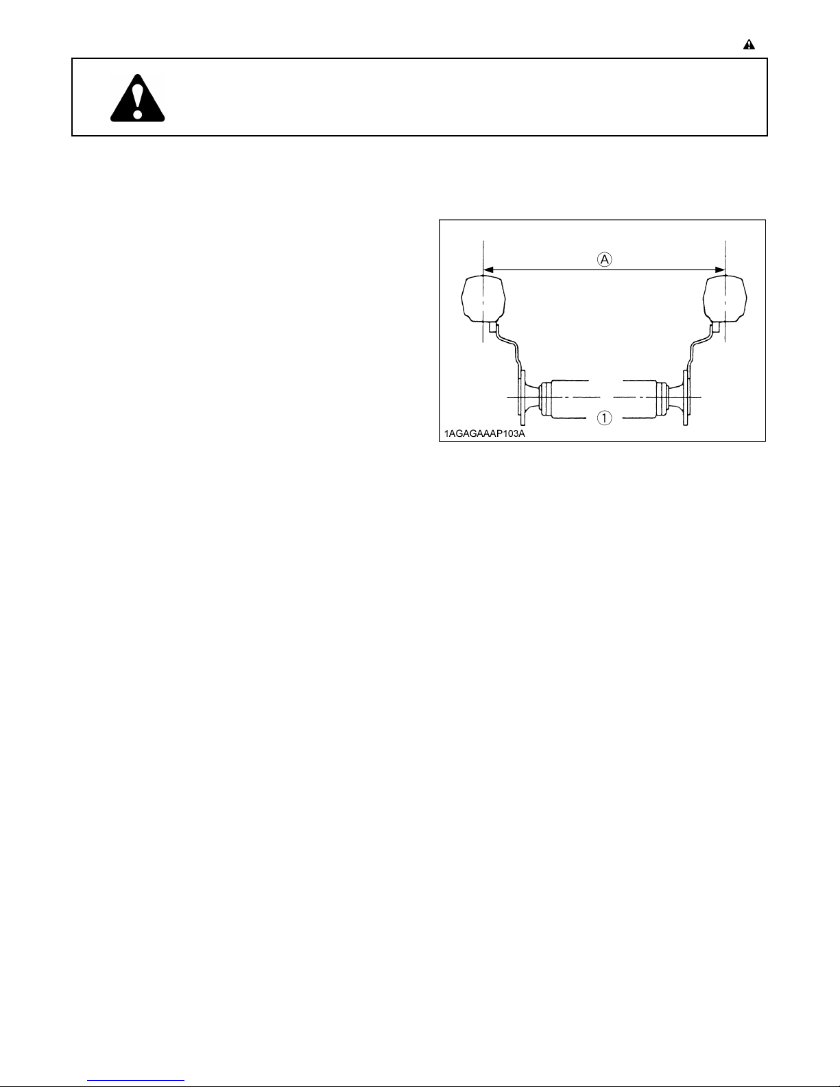
12. The narrower the tread, the greater the risk of a tractor
upset. For maximum stability, adjust the wheels to the
widest practical tread width for your application. (See
"TIRES, WHEELS AND BALLAST" section.)
(1) Rear wheels (A) Tread Width
13.Do not modify the tractor. Unauthorized modification
may affect the function of the tractor, which may result
in personal injury.
C CAB, ROPS
1. KUBOTA recommends the use of a CAB or Roll Over
Protective Structures (ROPS) and seat belt in almost
all applications. This combination will reduce the risk
of serious injury or death, should the tractor be upset.
Check for overhead clearance which may interfere
with a CAB or ROPS.
2. If the CAB or ROPS is loosened or removed for any
reason, make sure that all parts are reinstalled
correctly before operating the tractor.
3. Never modify or repair any structural member of a
CAB or ROPS because welding, bending, drilling,
grinding, or cutting may weaken the structure.
4. A damaged CAB or ROPS structure must be replaced,
not repaired or revised.
5. If any structural member of the CAB or ROPS is
damaged, replace the entire structure at your local
KUBOTA Dealer.
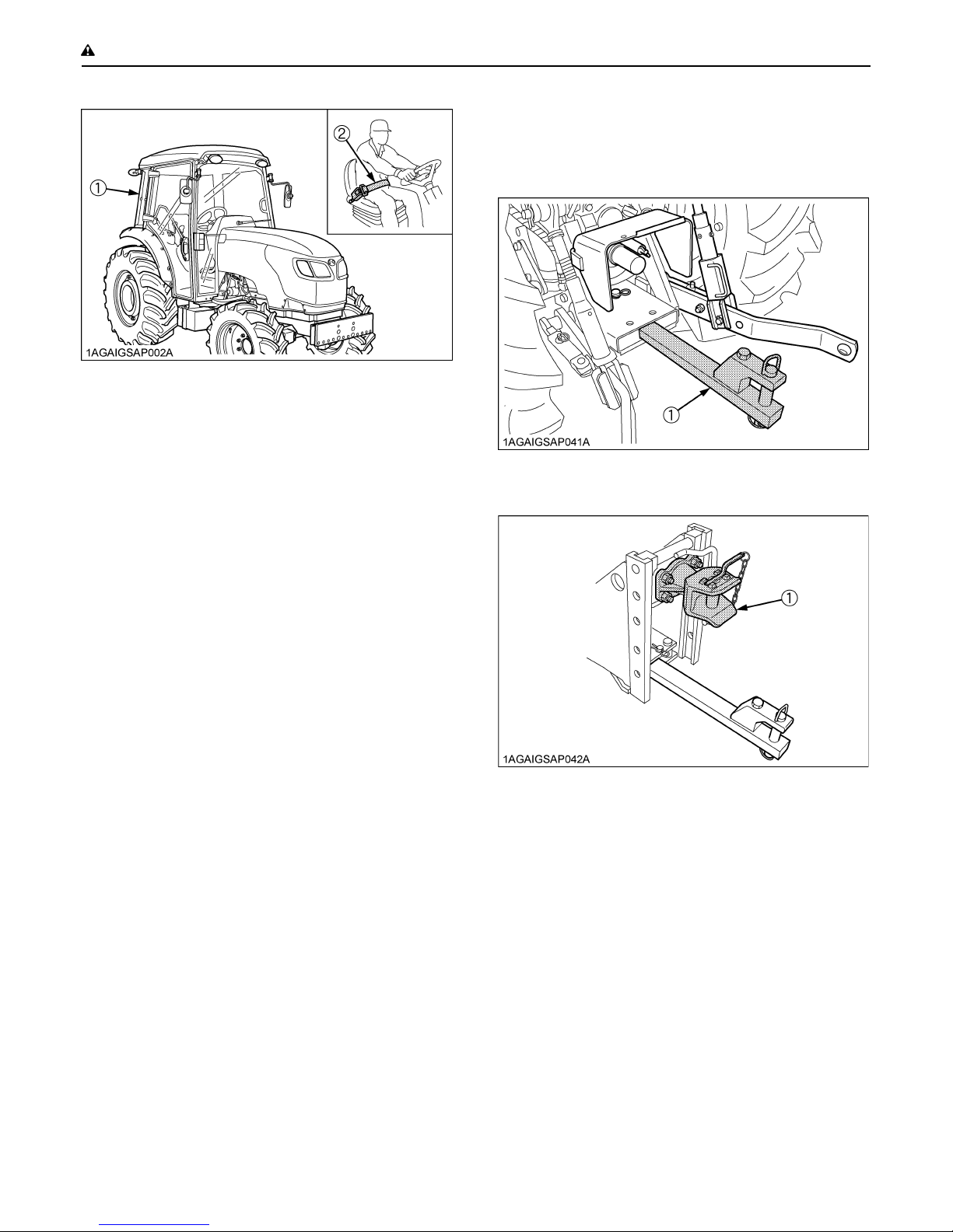
6. Always use the seat belt if the tractor has a CAB or
ROPS.
Do not use the seat belt if a foldable ROPS is down or
there is no ROPS. Check the seat belt regularly and
replace if frayed or damaged.
Page 13
SAFE OPERATION-2
(1) CAB
(2) Seat belt
C Working
1. Pull only from the hitch devices. Never hitch to axle
housing or any other point except drawbar; such
arrangements will increase the risk of serious personal
injury or death due to a tractor upset.
2. OPERATING THE TRACTOR
Operator safety is a priority. Safe operation, specifically
with respect to overturning hazards, entails understanding
the equipment and environmental conditions at the time of
use. Some prohibited uses which can affect overturning
hazards include traveling and turning with implements
and loads carried too high etc. This manual sets forth
some of the obvious risks, but the list is not, and cannot
be, exhaustive. It is the operator's responsibility to be alert
for any equipment or environmental condition that could
compromise safe operation.
C Starting
1. Always sit in the operator's seat when starting engine
or operating levers or controls. Adjust seat per
instructions in the operating the tractor section. Never
start engine while standing on the ground.
2. Before starting the engine, make sure that all levers
(including auxiliary control levers) are in their neutral
positions, that the parking brake is engaged, and that
both the clutch and the Power Take-Off (PTO) are
disengaged or "OFF".
Fasten the seat belt if the tractor has a CAB, a fixed
ROPS or a foldable ROPS in the upright and locked
position.
3. Do not start engine by shorting across starter
terminals or bypassing the safety start switch.
Machine may start in gear and move if normal starting
circuitry is bypassed.
4. Do not operate or idle engine in a non-ventilated area.
Carbon monoxide gas is colorless, odorless, and
deadly.
5. Check before each use that operator presence
controls are functioning correctly. Test safety systems.
(See "Checking Engine Start System" in "EVERY 50
HOURS" in "PERIODIC SERVICE" section.)
Do not operate unless they are functioning correctly.
(1) Drawbar
(1) High-hitch
2. For trailing PTO-driven implements, set the hitch
devices to the towing position.
3. Attach pulled or towed loads to the hitch devices only.
4. Keep all shields and guards in place. Replace any that
are missing or damaged.
5. Avoid sudden starts. To avoid upsets, slow down
when turning, on uneven ground, and before stopping.
6. The tractor cannot turn with the differential locked and
attempting to do so could be dangerous.
7. Do not operate near ditches, holes, embankments, or
other ground surface features which may collapse
under the tractor's weight. The risk of tractor upset is
even higher when the ground is loose or wet. Tall
grass can hide obstacles, walk the area first to be sure.
8. Watch where you are going at all times. Watch for and
avoid obstacles. Be alert at row ends, near trees, and
other obstructions.
9. When working in groups, always let the others know
what you are going to do before you do it.
Page 14
-3SAFE OPERATION
10.Never try to get on or off a moving tractor.
11.Always sit in the operator's seat when operating levers
or controls.
12.Do not use "Bi-speed Turn" at high speed.
13."Bi-Speed Turn" enables short and fast turns,
therefore, become familiar with its performance before
operating in close or confined areas.
14.Do not stand between tractor and implement or trailed
vehicle unless parking brake is applied.
C Safety for children
Tragedy can occur if the operator is not alert to the
presence of children. Children generally are attracted to
machines and the work they do.
1. Never assume that children will remain where you last
saw them.
2. Keep children out of the work area and under the
watchful eye of another responsible adult.
3. Be alert and shut your machine down if children enter
the work area.
4. Never carry children on your machine. There is no safe
place for them to ride. They may fall off and be run
over or interfere with your control of the machine.
5. Never allow children to operate the machine even
under adult supervision.
6. Never allow children to play on the machine or on the
implement.
7. Use extra caution when backing up. Look behind and
down to make sure area is clear before moving.
7. To avoid free wheeling:
A Do not shift the shuttle lever while on a slope.
A Stop completely by using the brake and by
depressing the clutch pedal, then shift the shuttle
lever.
A Start off after selecting shuttle direction, by
releasing the clutch pedal.
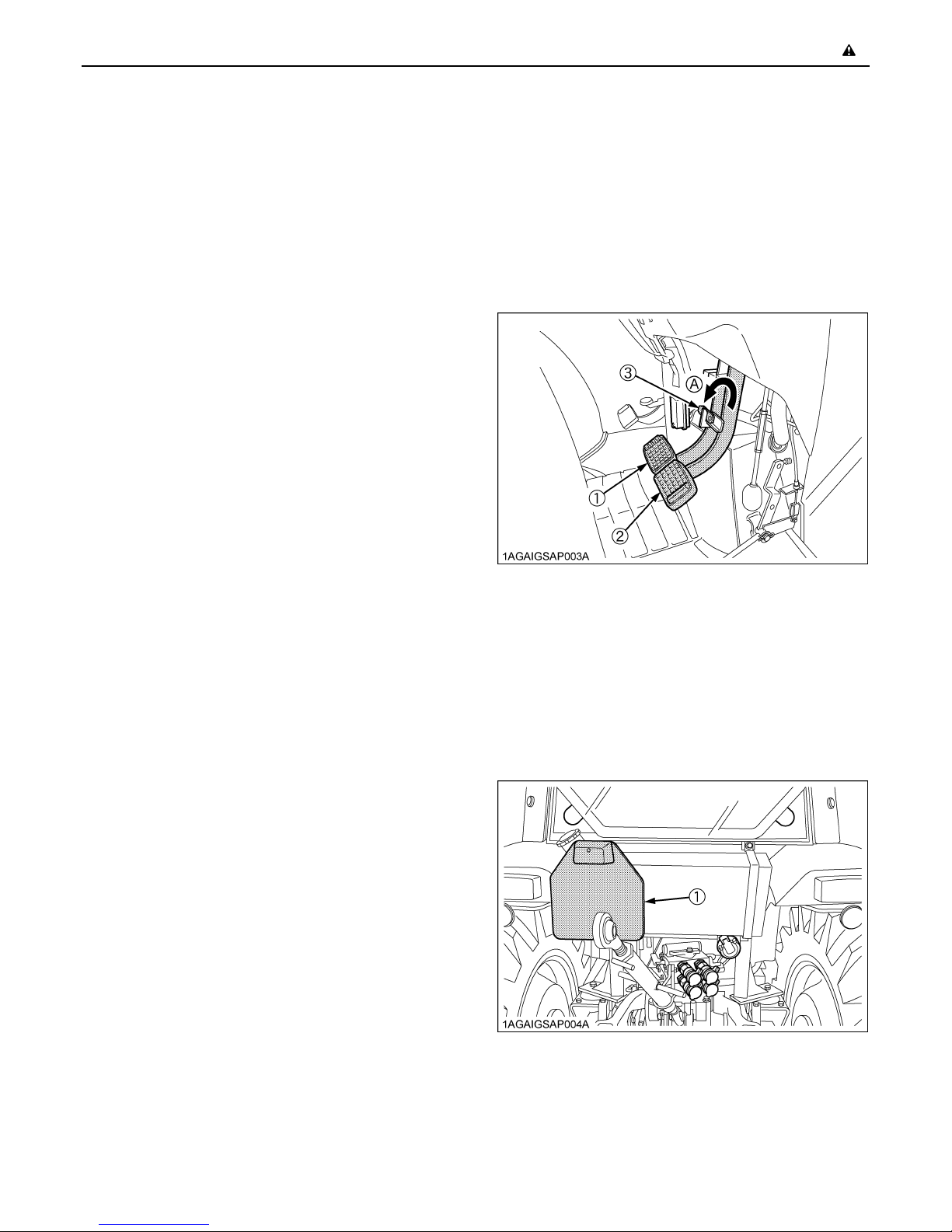
C Driving the tractor on the road
1. Lock the two brake pedals together to help assure
straight-line stops. Uneven braking at road speeds
could cause the tractor to tip over.
(1) Brake Pedal (LH)
(2) Brake Pedal (RH)
(3) Brake Pedal Lock
(A) Whenever travelling on the road
C Operating on slopes
Slopes are a major factor related to loss-of-control and tipover accidents, which can result in severe injury or death.
All slopes require extra caution.
1. To avoid upsets, always back up steep slopes. If you
cannot back up the slope or if you feel uneasy on it, do
not operate on it. Stay off slopes too steep for safe
operation.
2. Driving forward out of a ditch, mired condition or up a
steep slope increases the risk of a tractor to be upset
backward. Always back out of these situations. Extra
caution is required with four-wheel drive models
because their increased traction can give the operator
false confidence in the tractor's ability to climb slopes.
3. Keep all movement on slopes slow and gradual. Do
not make sudden changes in speed, direction or apply
brake and make sudden motions of the steering
wheel.
4. Avoid disengaging the clutch or changing gears speed
when climbing or going down a slope. If on a slope
disengaging the clutch or changing gears to neutral
could cause loss of control.
5. Special attention should be made to the weight and
location of implements and loads as such will affect the
stability of the tractor.
6. To improve stability on slope, set widest wheel tread
as shown in "TIRES, WHEELS AND BALLAST"
section.
Follow recommendations for proper ballasting.
2. Check the front wheel engagement. The braking
characteristics are different between two and four
wheel drive. Be aware of the difference and use
carefully.
3. Always slow the tractor down before turning. Turning
at high speed may tip the tractor over.
4. Observe all local traffic and safety regulations.
Use the registration plate as required.
(1) Registration plate
5. Turn the headlights on. Dim them when meeting
another vehicle.
6. Drive at speeds that allow you to maintain control at all
times.
Page 15
SAFE OPERATION-4
7. Do not apply the differential lock while traveling at road
speeds. The tractor may run out of control.
8. Avoid sudden motions of the steering wheel as they
can lead to a dangerous loss of stability. The risk is
especially great when the tractor is traveling at road
speeds.
9. Do not operate an implement while the tractor is on the
road. Lock the 3-point hitch in the raised position.
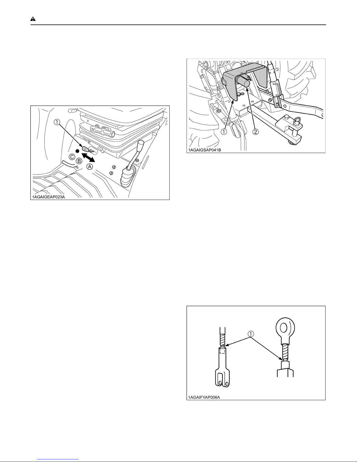
10.Set the implement lowering speed lever in the "LOCK"
position to hold the implement in the raised position.
(1) 3-point hitch lowering speed lever (A) "FAST"
(B) "SLOW"
(C) "LOCK"
2. Keep the PTO shaft cover in place at all times.
Replace the PTO shaft cap when the shaft is not in
use.
(1) PTO Shaft cover
(2) PTO Shaft cap
3. Before installing or using PTO driven equipment, read
the manufacturer's manual and review the safety
labels attached to the equipment.
4. When operating stationary PTO driven equipment,
always apply the tractor parking brake and place
chocks behind and in front of the rear wheels. Stay
clear of all rotating parts. Never step over rotating
parts.
3. PARKING THE TRACTOR
1. Disengage the PTO, lower all implements to the
ground, place all control levers in their neutral
positions, set the parking brake, stop the engine,
remove the key from the ignition and lock the cab door
(if equipped). Leaving transmission in gear with the
engine stopped will not prevent tractor from rolling.
2. Make sure that the tractor has come to a complete
stop before dismounting.
3. Avoid parking on steep slopes, if at all possible park on
a firm and level surface; if not, park across a slope with
chock the wheels.
Failure to comply with this warning may allow the
tractor to move and could cause injury or death.
4. OPERATING THE PTO
1. Wait until all moving components have completely
stopped before getting off the tractor, connecting,
disconnecting, adjusting, cleaning, or servicing any
PTO driven equipment.
5. USING 3-POINT HITCH
1. Use the 3-point hitch only with equipment designed for
3-point hitch usage.
2. When using a 3-point hitch mounted implement, be
sure to install the proper counterbalance weight on the
front of the tractor.
3. To avoid injury from separation:
Do not extend lift rod beyond the groove on the
threaded rod.
(1) Groove
Page 16
6. SERVICING THE TRACTOR
Before servicing the tractor, park it on a firm, flat and level
surface, set the parking brake, lower all implements to the
ground, place the gear shift lever in neutral, stop the
engine and remove the key.
1. Allow the tractor time to cool off before working on or
near the engine, muffler, radiator, etc.
2. Do not remove radiator cap while coolant is hot. When
cool, slowly rotate cap to the first stop and allow
sufficient time for excess pressure to escape before
removing the cap completely. If the tractor has a
coolant recovery tank, add coolant or water to the tank,
not the radiator. (See "Checking Coolant Level" in
"DAILY CHECK" in "PERIODIC SERVICE" section.)
3. Always stop the engine before refueling. Avoid spills
and overfilling.
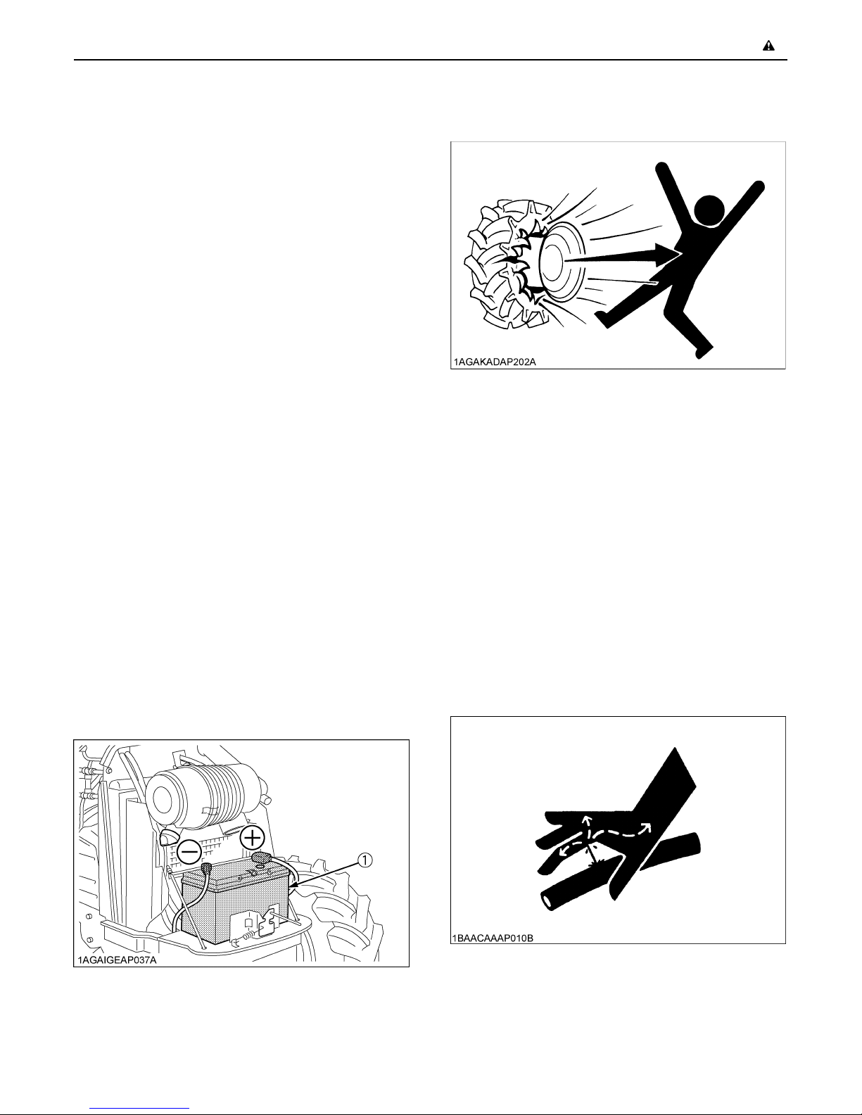
4. Do not smoke when working around battery or when
refueling. Keep all sparks and flames away from
battery and fuel tank. The battery presents an
explosive hazard, because it gives off hydrogen and
oxygen especially when recharging.
5. Before "jump starting" a dead battery, read and follow
all of the instructions. (See "JUMP STARTING" in
"OPERATING THE ENGINE" section.)
6. Keep first aid kit and fire extinguisher handy at all
times.
7. Disconnect the battery's ground cable before working
on or near electric components.
8. To avoid the possibility of battery explosion, do not use
or charge the refillable type battery if the fluid level is
below the LOWER ( lower limit level ) mark. Check the
fluid level regularly and add distilled water as required
so that the fluid level is between the UPPER and
LOWER levels.
9. To avoid sparks from an accidental short circuit,
always disconnect the battery's ground cable (-) first
and reconnect it last.
-5SAFE OPERATION
11.Always maintain the correct tire pressure. Do not
inflate tires above the recommended pressure shown
in the operator's manual.
12.Securely support the tractor when either changing
wheels or adjusting the wheel tread width.
13.Make sure that wheel bolts have been tightened to the
specified torque.
14.Disconnect the battery's ground cable and stop the
engine to avoid the possibility of the machine runaway
due to 4WD braking system during testing, service or
repair with only rear wheels off the ground.
15.Do not work under any hydraulically supported
devices. They can settle, suddenly leak down, or be
accidentally lowered. If it is necessary to work under
tractor or any machine elements for servicing or
adjustment, securely support them with stands or
suitable blocking beforehand.
16.Escaping hydraulic fluid under pressure has sufficient
force to penetrate skin, causing serious personal
injury. Before disconnecting hydraulic lines, be sure to
release all residual pressure. Before applying
pressure to the hydraulic system, make sure that all
connections are tight and that all lines, pipes, and
hoses are free of damage.
(1) Battery
10.Do not attempt to mount a tire on a rim. This should be
done by a qualified person with the proper equipment.
Page 17
SAFE OPERATION-6
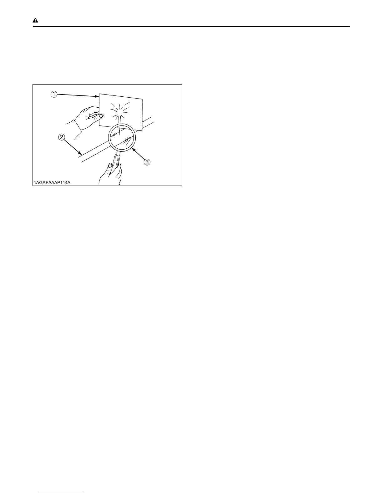
17.Fluid escaping from pinholes may be invisible. Do not
use hands to search for suspected leaks; use a piece
of cardboard or wood. Use of safety goggles or other
eye protection is also highly recommended. If injured
by escaping fluid, see a medical doctor at once. This
fluid will produce gangrene or severe allergic reaction.
(1) Cardboard
(2) Hydraulic line
(3) Magnifying glass
18.Waste products such as used oil, fuel, hydraulic fluid,
and batteries, can harm the environment, people, pets
and wildlife. Please dispose properly.
See your local Recycling Center or KUBOTA Dealer to
learn how to recycle or get rid of waste products.
Page 18
-7SAFE OPERATION
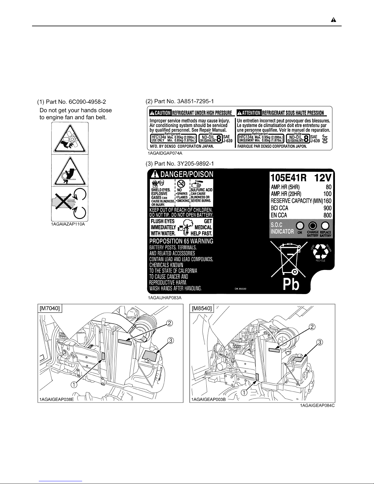
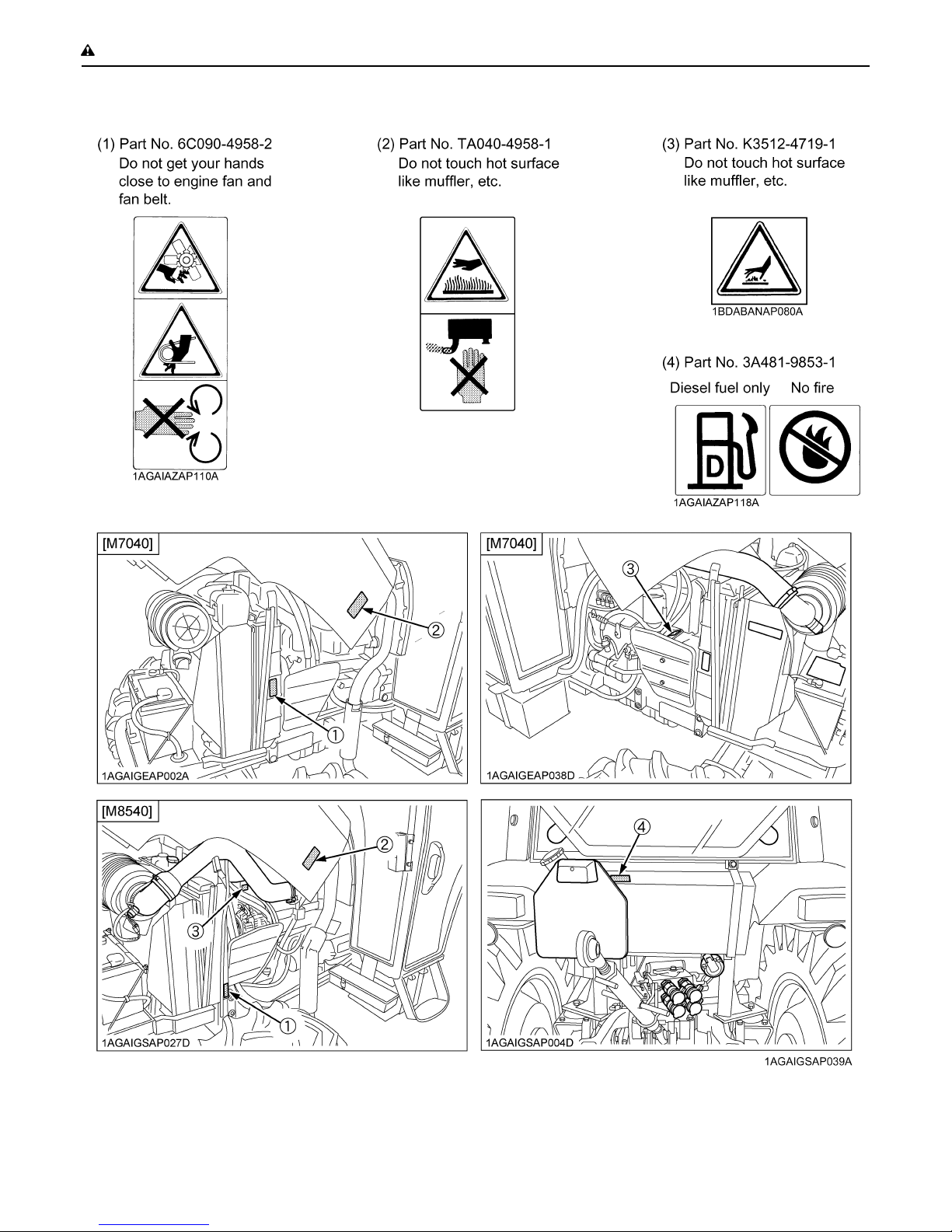
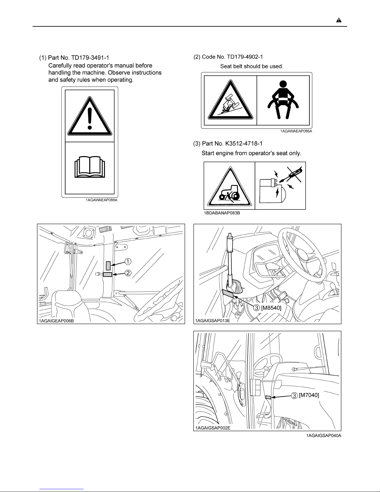
7. PICTORIAL SAFETY LABELS
The pictorial safety labels affixed are intended to alert persons to potential hazards. The hazard is identified by a pictorial
in the safety alert triangle or by the safety alert symbol alone. An adjacent pictorial provides instructions and information
on how to avoid the hazard.
Page 19
SAFE OPERATION-8
Page 20
-9SAFE OPERATION
Page 21

SAFE OPERATION-10
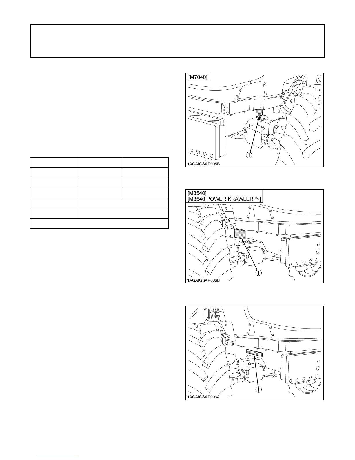
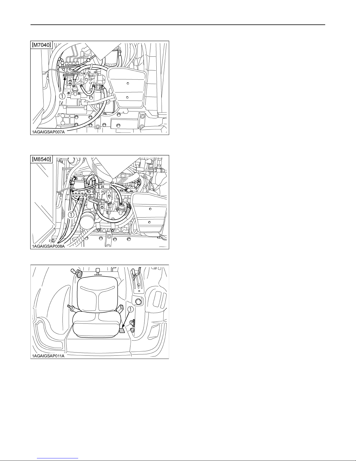
8. CARE OF PICTORIAL SAFETY LABELS
1. Keep pictorial safety labels clean and free from obstructing material.
2. Clean pictorial safety labels with soap and water, dry with a soft cloth.
3. Replace damaged or missing pictorial safety labels with new labels from your local KUBOTA Dealer.
4. If a component with pictorial safety label(s) affixed is replaced with new part, make sure new label(s) is (are) attached
in the same location(s) as the replaced component.
5. Mount new pictorial safety labels by applying on a clean dry surface and pressing any bubbles to outside edge.
Page 22
SERVICING OF TRACTOR
Your dealer is interested in your new tractor and has the
desire to help you get the most value from it. After reading
this manual thoroughly, you will find that you can do some
of the regular maintenance yourself.
However, when in need of parts or major service, be sure
to see your KUBOTA Dealer.
For service, contact the KUBOTA Dealership from which
you purchased your tractor or your local KUBOTA Dealer.
When in need of parts, be prepared to give your dealer the
tractor, CAB/ROPS and engine serial numbers.
Locate the serial numbers now and record them in the
space provided.
Type Serial No.
1SERVICING OF TRACTOR
Tractor
CAB / ROPS
Engine
Date of Purchase
Name of Dealer
(To be filled in by purchaser)
C Warranty
This tractor is warranted under the KUBOTA Limited
Express Warranty, a copy of which may be obtained from
your selling dealer. No warranty shall, however, apply if
the tractor has not been handled according to the
instruction given in the Operator's Manual even it is within
the warranty period.
C Scrapping the tractor and its procedure
To put the tractor out of service, correctly follow the local
rules and regulations of the country or territory where you
scrap it. If you have questions, consult your local
KUBOTA Dealer.
(1) Tractor identification plate
(1) Tractor identification plate
(1) Tractor serial number
Page 23
SERVICING OF TRACTOR2
(1) Engine serial number
(1) Engine serial number
(1) CAB identification plate (CAB Serial No.)
Page 24

SPECIFICATIONS
SPECIFICATION TABLE
3SPECIFICATIONS
Engine
Model
Model V3307-DI-TE3 V3800-DI-TE3
Type Direct Injection, liquid cooled 4 cylinder diesel
Number of cylinders 4
Total displacement cm 3331 3769
Bore and stroke mm 94 x 120 100 x 120
Rated speed rpm 2600
Net power *1 kW (PS) 52.9 (72.0) 63.7 (86.7)
Gross power *1 kW (PS) 54.9 (74.6) 66.7 (90.7)
Maximum torque N-m / rpm 252 / 1500 to 1700 286 / 1500 to 1700
Battery capacity 12V, RC: 160 min, CCA 900A
Fuel tank capacity L 76
Engine oil capacity L 11 10.7
Coolant capacity L 8 9.0
Overall length
(with 3P)
mm 3620
M7040N M8540N
4WD 4WD
Overall width
(minimum tread)
Overall height mm 2240
Dimensions
Weight kg 2410 2460
Traveling
system
Wheel base mm 2050
Tread
Minimum ground clearance mm
Standard
tire size
Clutch Multiple wet disks
Steering Hydraulic Power Steering
Braking system Hydraulic wet disks mechanical
Trailer brake Hydraulic
Trailer brake couple ISO 5676
Differential Bevel gears with differential lock (Rear)
Front mm 1142, 1156
Rear mm 1060 to 1348
Front tires 280 / 70R18
Rear tires 380 / 70R28
mm 1430
370
(Drawbar bracket)
Page 25

4 SPECIFICATIONS
Model
Hydraulic control system Position, draft (top link sensing) & mix control
Pump capacity L / min 61
Three point hitch Category 1 (Category 2 Link end)
At lifting
Max. lifting
Hydraulic
unit
PTO
The level of protection against hazardous substance *2 Category 1
force
Remote hydraulic control 2 standard (3rd valve optional)
Remote control valve coupler ISO 7241-1 standards "A"
System pressure
Traction system Swinging drawbar, adjustable in direction
Live PTO
(Independent)
points
24 in. behind
lifting point
Direction of turning Clockwise, viewed from tractor rear
PTO/Engine
speed
kg
kg 1800
MPa
(kgf/cm )
rpm
M7040N M8540N
4WD 4WD
2300
At lower link end with links horizontal
19.1 (195)
6 spline: 540 / 2160
540E / 1828
CAB / door
Noise at the operator's ear
*3
Noise of the tractor in motion *4 dB(A) 83
Grammer
Value of the
vibration
level *5
The company reserves the right to change the specifications without notice.
NOTE: *1 Manufacturer's estimate
MSG93/511
COBO
SC74/M200
*2 According to EN 15695-1:2009
*3 Measured according to Directive 2009/76/EC
*4 Measured according to Council Directive 2009/63/EC
*5 Measured according to Council Directive 78/764/EEC
closed
CAB / door
opened
Light driver m/s 1.21
Heavy driver m/s 1.05
Light driver m/s 1.22
Heavy driver m/s 1.06
dB(A) 82.0
dB(A) 86.0
Page 26

TRAVELING SPEEDS
Model M7040N, M8540N
Tire size (Rear) 380 / 70R28
Shuttle
shift lever
Range gear
shift lever
CREEP
L
H
CREEP
L
H
Main gear
shift lever
5SPECIFICATIONS
(At rated engine rpm)
km/h
1 0.40
2 0.57
3 0.74
4 0.94
5 1.24
1 2.8
2 4.0
3 5.1
4 6.6
5 8.7
1 11.3
2 16.0
3 20.6
4 26.4
5 34.8
1 0.38
2 0.54
3 0.70
4 0.90
5 1.18
1 2.7
2 3.8
3 4.9
4 6.3
5 8.3
1 10.7
2 15.2
3 19.7
4 25.2
5 33.1
The company reserves the right to change the specifications without notice
Page 27
6 IMPLEMENT LIMITATIONS
IMPLEMENT LIMITATIONS
The KUBOTA Tractor has been thoroughly tested for proper performance with implements sold or approved by KUBOTA.
Use with implements which are not sold or approved by KUBOTA and which exceed the maximum specifications listed
below, or which are otherwise unfit for use with the KUBOTA Tractor may result in malfunctions or failures of the tractor,
damage to other property and injury to the operator or others. [Any malfunctions or failures of the tractor resulting from use
with improper implements are not covered by the warranty.]
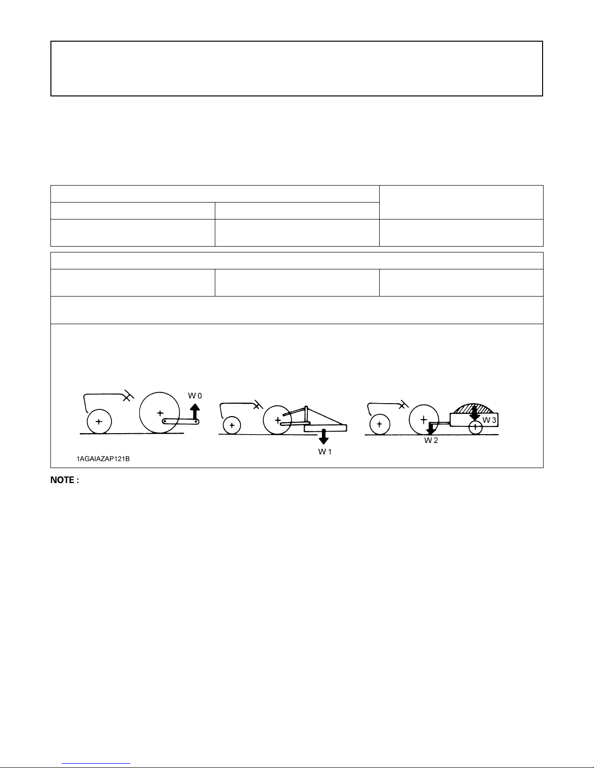
Tread (max. width)
Front Rear
1156 mm 1348 mm 2300 kg
Actual figures
Implement weight: W 1
and / or size
As in the following list (Shown on the next page)
Lower link end max, hydraulic lifting capacity.......................................W 0
Implement weight.............................................The implement's weight which can be put on the lower link: W 1
Max. drawbar load............................................W 2
Trailer loading weight.......................................The max. loading weight for trailer (without trailer's weight): W 3
Max. drawbar Load: W 2
Lower link end max. lifting capacity:
W 0
Trailer loading weight: W 3
Max. capacity
A Implement size may vary depending on soil operating conditions.
A Strictly follow the instructions outlined in the operator’s manual of the mounted or trailed machinery or trailer, and
do not operate the combination tractor - machine or tractor - trailer unless all instructions have been followed
A Forestry Application
Following hazards exist;
(a) toppling trees, primarily in case a rear-mounted tree grab-crane is mounted at the rear of the tractor;
(b) penetrating objects in the operator’s enclosure, primarily in case a winch is mounted at the rear of the tractor.
Optional equipments such as OPS (Operator Protective Structure), FOPS (Falling Object Protective Structure), etc.
to deal with these hazards and other related hazards are not available for this tractor. Without such optional
equipment use is limited to tractor specific applications like transport and stationary work.
Page 28

7IMPLEMENT LIMITATIONS
No. Implement Remarks
1Trailer
2 Mower
3 Sprayer
4 Rotary Tiller
5 Bottom Plow
Disk
6
harrow
7 Disc Plow
8 Sub Soiler
9Cultivator
RotaryCutter
Flail Mower
(Heavy)
Sickle Bar Max. Cutting Width mm 2130
3P Type
Drawbar Max. Harrowing Width mm 2750
Max. Load Capacity kg Shown on the next page
Max. Drawbar Load kg Shown on the next page
Max. Cutting Width mm 2130
Max. Weight kg 540
Max. Cutting Width mm 3050
Max. Weight kg 800
Max.TankCapacity
Max. Tilling Width mm 2130
Max. Weight kg 800
Max. Size
Max. Weight kg 3P Type 450
Max. Size 18 in. x 24
Max. Harrowing Width mm 2130
Max. Weight kg 450
Max. Size
Max. Weight kg 450
Numbers of Cultivating Tines 2
Cultivating Depth mm 400
Max. Width mm 3660
Number of Rows 4
Max. Weight kg 450
Mid L 680
Rear 3P L 680
Drawbar L 4000
M7040N M8540N
4WD 4WD
14 in. x 3
16 in. x 2
18 in. x 1
24 in. x 3
26 in. x 2
A Implement size may vary depending on soil operating conditions.
Page 29
8 IMPLEMENT LIMITATIONS
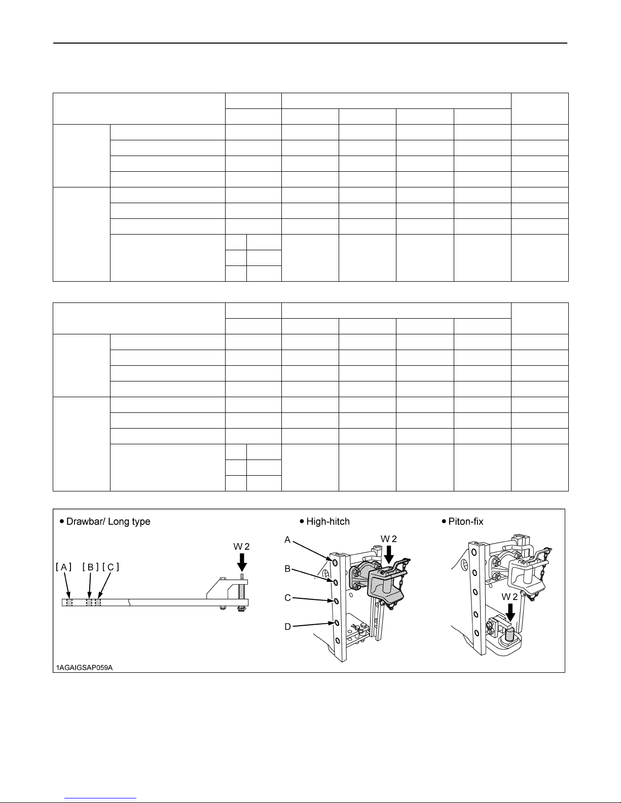
C Trailer Load Capacity
[M7040N, M8540N]
A 600 170 165 175 175 1800
Vertical load
(kg) W2
Unbraked towable mass 3000 3000 3000 3000 3000 3000
Trailer loading
weight max.
capacity (kg)
W3
Independently braked mass 5000 5000 5000 5000 5000 5000
Inertia-braked towable mass 6000 6000 6000 6000 6000 6000
Towable mass when fitted with
hydraulic or pneumatic braking
[POWER KRAWLER(TM) model]
Vertical load
(kg) W2
Unbraked towable mass 3000 3000 3000 3000 3000 3000
Trailer loading
weight max.
capacity (kg)
W3
Independently braked mass 5000 5000 5000 5000 5000 5000
Inertia-braked towable mass 6000 6000 6000 6000 6000 6000
Towable mass when fitted with
hydraulic or pneumatic braking
B 800 280 270 285 285 ---
C 900 400 390 410 410 ---
D --- 580 560 600 600 ---
A 600 170 165 175 175 1800
B 800 280 270 285 285 ---
C 900 400 390 410 410 ---
D --- 580 560 600 600 ---
Drawbar High-hitch
Long type Normal Automatic CUNA C CUNA D2
[A] 10000
8500 8500 6000 8500 8500[B] 10000
[C] 8500
Drawbar High-hitch
Long type Normal Automatic CUNA C CUNA D2
[A] 10000
--- --- --- --- ---[B] 10000
[C] 8500
Piton-fix
Piton-fix
Page 30
9INSTRUMENT PANEL AND CONTROLS
INSTRUMENT PANEL AND CONTROLS
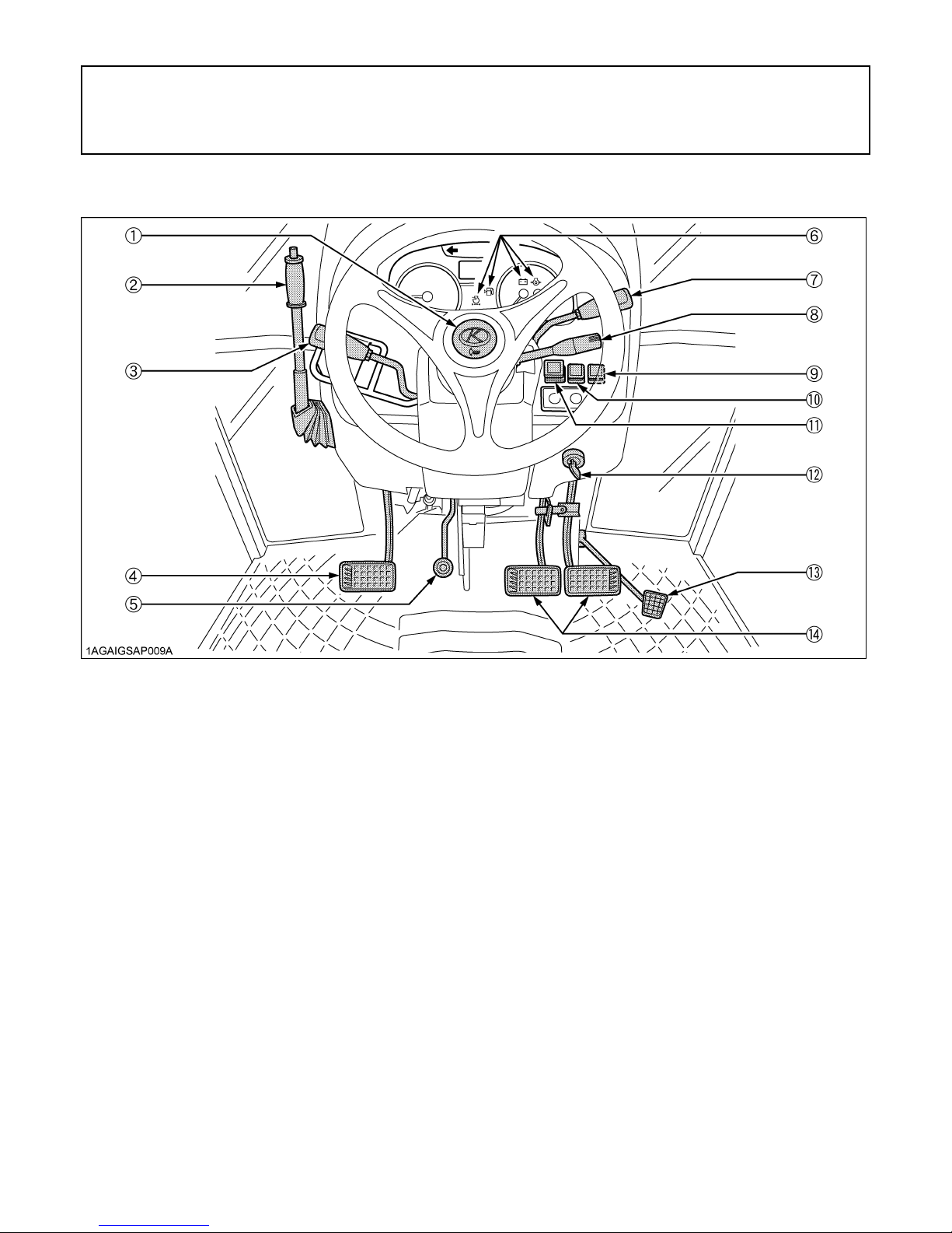
B Instrument Panel, Switches and Hand Controls
ILLUSTRATED CONTENTS
(1) Horn button....................................................... 23
(2) Parking brake lever........................................... 27
(3) Hydraulic-shuttle shift lever............................... 25
(4) Clutch pedal...................................................... 24
(5) Tilt pedal........................................................... 21
(6) Easy Checker(TM)............................................ 28
(7) Hand throttle lever............................................. 27
(8) Turn signal / Head light switch........................... 22,22
(9) Beacon light switch........................................... 66
(10) Hazard light switch.......................................... 22
(11) 4WD / Bi-Speed Turn switch........................... 26
(12) Key switch....................................................... -
(13) Foot throttle..................................................... 27
(14) Brake pedal..................................................... 23
Page 31
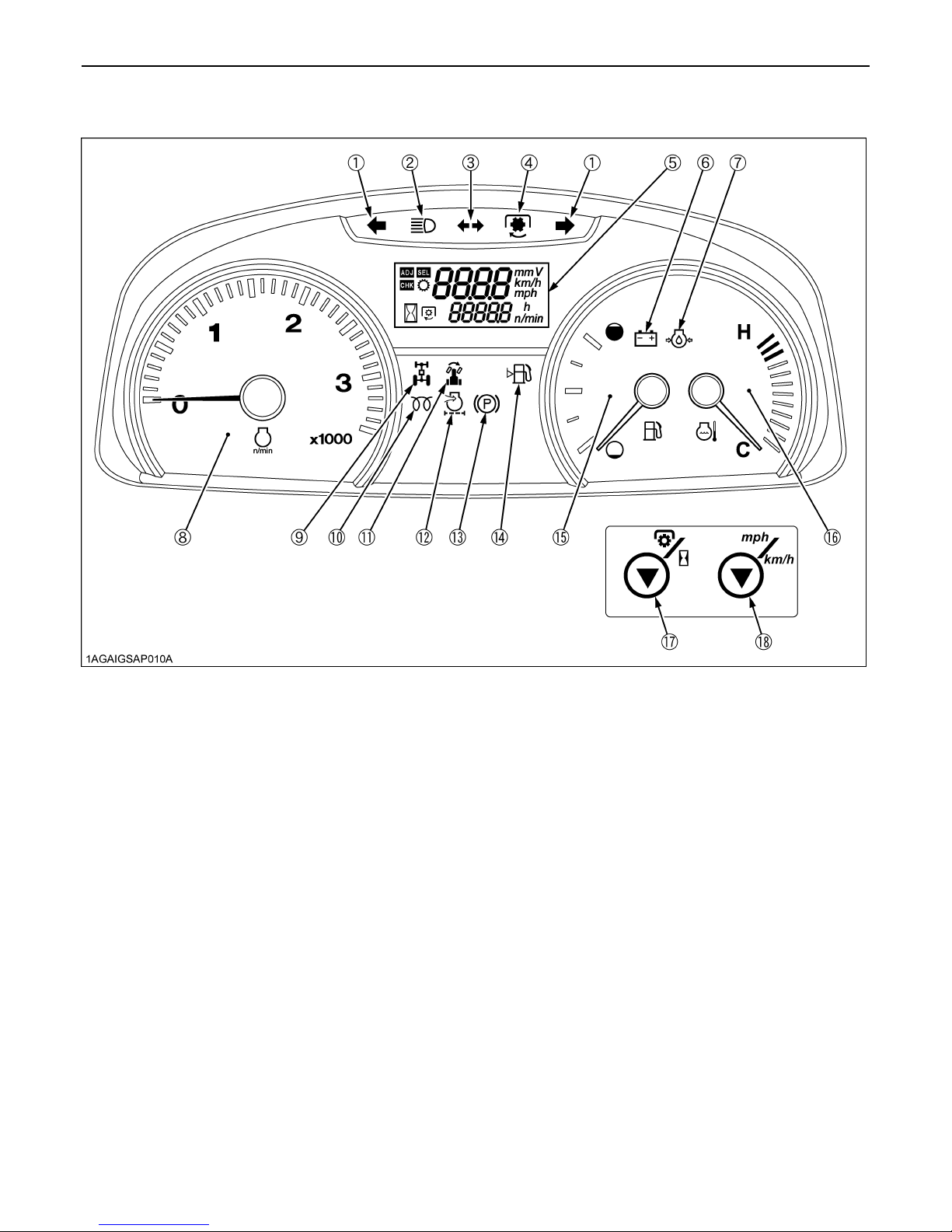
10 INSTRUMENT PANEL AND CONTROLS
ILLUSTRATED CONTENTS ILLUSTRATED CONTENTS
(1) Hazard / Turn signal indicator ............................ 22 (11) Bi-Speed Turn indicator ................................. 26
(2) High beam indicator ........................................... 22 (12) Air cleaner indicator........................................ 28
(3) Trailer indicator................................................... 22 (13) Parking brake indicator .................................. 27
(4) PTO clutch indicator........................................... 37 (14) Fuel level indicator ......................................... 28
(5) Liquid crystal display .......................................... 30 (15) Fuel gauge...................................................... 29
(6) Electrical charge indicator .................................. 28 (16) Coolant temperature gauge............................ 29
(7) Engine oil pressure indicator .............................. 28 (17) PTO / Hour meter select switch....................... 30
(8) Tachometer ....................................................... 29 (18) Travel speed select switch.............................. 30
(9) 4WD indicator .................................................... 26
(10) Glow plug indicator [M7040]
Heater indicator [M8540] ................................. 16
Page 32

B Foot and Hand Controls
11INSTRUMENT PANEL AND CONTROLS
ILLUSTRATED CONTENTS
(1) Tool box..................................................... -
(2) Differential lock pedal................................. 34
(3) 3-Point hitch lowering speed lever............. 50
(4) Range gear shift lever................................ 25
(5) Ground / Engine PTO select lever
(if equipped)............................................... 40
(6) Operator's seat.......................................... 20
(7) Seat belt..................................................... 21
(8) Main gear shift lever................................... 25
(9) Remote control valve lever......................... 51
(10) Position control lever................................ 49
(11) Draft control lever..................................... 49
(12) PTO clutch control switch......................... 37
(13) Electrical outlet........................................ 66
(14) Electrical outlet........................................ 66
(15) Electrical outlet........................................ 66
(16) Front work light switch.............................. 60
(17) Rear work light switch.............................. 60
(18) Front wiper / Washer switch..................... 60
(19) Rear wiper / Washer switch (if equipped). 60
Page 33

12 INSTRUMENT PANEL AND CONTROLS
ILLUSTRATED CONTENTS
(1) Trailer electrical outlet............................ 36
(2) PTO gear shift lever............................... 38
(3) Remote control valve coupler................ 52
(4) Trailer hydraulic brake outlet
(if equipped)..........................................
36
Page 34

PRE-OPERATION CHECK
DAILY CHECK
To prevent trouble from occurring, it is important to know
the condition of the tractor well. Check it before starting.
To avoid personal injury:
A Be sure to check and service the tractor on a
level surface with the engine shut off and the
parking brake "ON" and implement lowered to
the ground.
Check item
- Walk around inspection
- Check engine oil level
- Check transmission oil level
- Check coolant level
- Check washer liquid level
- Check water separator
- Clean grill and radiator screen
- Clean air conditioner condenser screen
- Clean oil cooler
- Check air cleaner evacuator valve
(When used in a dusty place)
- Check brake pedal
- Check parking brake lever
- Check indicators, gauges and meter
- Check lights
- Check seat belt
- Refuel
(See "DAILY CHECK" in "PERIODIC SERVICE"
section.)
- Care of pictorial safety labels
(See "PICTORIAL SAFETY LABELS" in "SAFE
OPERATION" section.)
13PRE-OPERATION CHECK
Page 35

14 OPERATING THE ENGINE
OPERATING THE ENGINE
To avoid personal injury:
A Read "Safe Operation" in the front of this
manual.
A Understand the pictorial safety labels located
on the tractor.
A To avoid the danger of exhaust fume
poisoning, do not operate the engine in a
closed building without proper ventilation.
A Never start engine while standing on ground.
Start engine only from operator's seat.
A Make it a rule to set all shift levers to the
"NEUTRAL" positions and to place PTO clutch
control switch in "OFF" position before starting
the engine.
(1) Parking brake indicator light
A Do not use starting fluid or ether.
A To protect the battery and the starter, make sure that
the starter is not continuously turned for more than 10
seconds.
STARTING THE ENGINE
1. Make sure the parking brake is set.
Pull the parking brake lever rearward to park.
The parking brake indicator light on the Easy
Checker(TM) will come on while the parking brake is set.
A If the tractor is operated with the parking brake set, the
parking brake will be damaged.
2. Make sure the fuel cock is in the
"OPEN" position.
(1) Fuel cock (A) "CLOSE"
(B) "OPEN"
(1) Parking brake lever
(2) Release button
(A) "PULL"
Page 36

15OPERATING THE ENGINE
3. Place the shift levers in "NEUTRAL"
position.
(1) Hydraulic-shuttle shift lever
(2) Main gear shift lever
(N) "NEUTRAL POSITION"
4. Place the PTO clutch control switch in
"OFF" position and hydraulic control
levers in "LOWEST" position.
5. Set the throttle lever to about 1/2 way.
(1) Hand throttle lever
(2) Foot throttle
(A) "INCREASE"
(B) "DECREASE"
6. Insert the key into the key switch and
turn it "ON".
(1) PTO clutch control switch
(2) Position control lever
(3) Draft control lever
(A) "DOWN"
"ON" "OFF"
"OFF" (Engine-Stop) "ON" (Engine-Run)
ACC
NOTE:
ACC... A The accessories can be used while the
Electrical
Power-accessories
engine is stopped.
A Do not leave the key at "ACC" position. The
battery will be quickly discharged. Turn it
back to "OFF" after use.
"START"
(Engine-Start)
Page 37

OPERATING THE ENGINE16
C Check Easy Checker(TM) Lamps:
1. When the key is turned "ON", lamps (2) (3) (5) should
come on. If trouble should occur at any location while
the engine is running, the indicator lamp
corresponding to that location comes on.
2. Suppose that the engine coolant temperature is not
high enough yet. The indicator (4) also comes on when
the key is turned "ON" to preheat the engine and goes
off automatically when preheat is completed.
Illumination time of indicator varies according to the
temperature of coolant
3. The PTO clutch indicator (1) comes on while PTO
clutch control switch is engaged "ON" and goes off
when disengaged "OFF" it.
9. Check to see that all the lamps on the
Easy Checker(TM) are "OFF".
If a lamp is still on, immediately stop the engine and
determine the cause.
10. Release the clutch pedal.
COLD WEATHER STARTING
If the ambient temperature is below 0 and the engine is
very cold, follow the procedure below after taking the step
1 through 5 in the previous pages.
6. Turn the key to "ON" position and hold it
until the indicator turns off.
The indicator comes on when the key is turned to "ON"
position and engine coolant temperature is below 0 ,
and goes off automatically when preheat is completed.
(1) PTO clutch indicator
(2) Electrical charge indicator
(3) Engine oil pressure indicator
A Some of the Easy Checker(TM) lamps may come on
or go off depending on the positions of the lever and
switch.
A Daily checks with the Easy Checker(TM) only, are not
sufficient. Never fail to conduct daily checks carefully
by referring to Daily Check.
(See "DAILY CHECK" in "PERIODIC SERVICE"
section.)
(4) Glow plug /
Heater indicator
(5) Air cleaner indicator
7. Fully depress the clutch pedal.
8. Turn the key to "START" position and
release when the engine starts.
A Because of the safety devices, the engine will not start
except when the PTO clutch control switch is placed in
the "OFF" position and shuttle shift lever is placed in
the "NEUTRAL" position.
(1) Glow plug / Heater indicator
7. Fully depress the clutch pedal.
8. Turn the key to the "START" position
and the engine should start.
(If the engine fails to start after 10 seconds, turn off the
key for 30 seconds. Then repeat steps 6 through 8. To
protect the battery and the starter, make sure that the
starter is not continuously turned for more than 10
seconds.)
Page 38

BBlock Heater (if equipped)
A block heater is available as an option from your dealer.
It will assist you in starting your tractor when the ambient
temperature is below -20 .
STOPPING THE ENGINE
1. After slowing the engine to idle, wait 3 to
5 minutes for turbo to slow down and
then turn the key to "OFF".
17OPERATING THE ENGINE
JUMP STARTING
To avoid personal injury:
A Battery gases can explode. Keep cigarettes,
sparks, and flames away from battery.
A If tractor battery is frozen, do not jump start
engine.
A Do not connect other end of negative (-) jumper
cable to negative (-) terminal of tractor battery.
2. Remove the key.
A If key does not stop the engine, consult your local
KUBOTA Dealer.
WARMING UP
To avoid personal injury:
A Be sure to set the parking brake during warm-
up.
A Be sure to set all shift levers to the "NEUTRAL"
positions and to place PTO switch in "OFF"
position during warm-up.
For five minutes after engine start-up, allow engine to
warm up without applying any load, this is to allow oil to
reach every engine part. If load should be applied to the
engine without this warm-up period, trouble such as
seizure, breakage or premature wear may develop.
BWarm-up and Transmission Oil at Low
Temperature Range
Hydraulic oil serves as transmission fluid. In cold weather,
the oil may be cold with increased viscosity. This can
cause delayed oil circulation or abnormally low hydraulic
pressure for some time after engine start-up. This in turn
can result in trouble in the hydraulic system.
To prevent the above, observe the following instructions:
Warm up the engine at about 50 % of rated rpm according
to the table below:
When jump starting engine, follow the instructions below
to safely start the engine.
1. Bring helper vehicle with a battery of the same voltage
as disabled tractor within easy cable reach. "THE
VEHICLES MUST NOT TOUCH".
2. Engage the parking brakes of both vehicles and put
the shift levers in neutral. Shut both engines off.
3. Put on safety goggles and rubber gloves.
4. Ensure the vent caps are securely in place. (if
equipped)
5. Cover vent holes with damp rags. Do not allow the rag
to touch the battery terminals.
6. Attach the red clamp to the positive (red, (+) or pos.)
terminal of the dead battery and clamp the other end
of the same cable to the positive (red, (+) or pos.)
terminal of the helper battery.
7. Clamp the other cable to the negative (black, (-) or
neg.) terminal of the helper battery.
8. Clamp the other end to the engine block or frame of
the disabled tractor as far from the dead battery as
possible.
9. Start the helper vehicle and let its engine run for a few
moments. Start the disabled tractor.
10.Disconnect the jumper cables in the exact reverse
order of attachment. (Steps 8, 7 and 6).
11.Remove and discard the damp rags.
Ambient temperature Warm-up time requirement
Higher than -10 Approx. 10 minutes
-15 to -10 10 to 20 minutes
-20 to -15 20 to 30 minutes
Below -20 More than 30 minutes
A Do not operate the tractor under full load condition until
it is sufficiently warmed up.
Page 39

OPERATING THE ENGINE18
(1) Dead battery
(2) Lay a damp rag over the vent caps
(3) Jumper cables
(4) Helper battery
A This machine has a 12 volt negative (-) ground starting
system.
A Use only same voltage for jump starting.
A Use of a higher voltage source on tractor's electrical
system could result in severe damage to tractor's
electrical system.
Use only matching voltage source when "Jump
starting" a low or dead battery condition.
A Do not operate the tractor with the battery cable
disconnected from the battery.
A Do not operate the tractor without the battery
mounted.
A Do not operate the tractor with the battery dead.
Charge the battery fully enough before operating the
tractor.
Otherwise the tractor might malfunction.
Page 40

OPERATING THE TRACTOR
19OPERATING THE TRACTOR
OPERATING NEW TRACTOR
How a new tractor is handled and maintained determines
the life of the tractor.
A new tractor just off the factory production line has been,
of course, tested, but the various parts are not
accustomed to each other, so care should be taken to
operate the tractor for the first 50 hours at a slower speed
and avoid excessive work or operation until the various
parts become "broken-in". The manner in which the
tractor is handled during the "breaking-in" period greatly
affects the life of your tractor.
Therefore, to obtain the maximum performance and the
longest life of the tractor, it is very important to properly
break-in your tractor. In handling a new tractor, the
following precautions should be observed.
BDo not Operate the Tractor at Full Speed
for the First 50 Hours.
A Do not start quickly nor apply the brakes suddenly.
A In winter, operate the tractor after fully warming up the
engine.
A Do not run the engine at speeds faster than
necessary.
A On rough roads, slow down to suitable speeds. Do not
operate the tractor at fast speed.
The above precautions are not limited only to new
tractors, but to all tractors. But it should be especially
observed in the case of new tractors.
BOARDING AND LEAVING THE TRACTOR
1. Never try to get on or off a moving tractor or jump off
the tractor to exit.
2. Face the tractor when getting into or out of the tractor.
Do not use the controls as hand holds to prevent
inadvertent machine movements.
3. Always keep steps and floor clean to avoid slippery
conditions.
STARTING
1. Adjusting the Operator's Position.
A The seat and suspension should be adjusted to
ensure that the controls are comfortably at hand for the
operator, ensuring that the operator maintains a good
posture and minimizes risks from whole body
vibration.
BChanging Lubricating Oil for New Tractors
The lubricating oil is especially important in the case of a
new tractor. The various parts are not "broken-in" and are
not accustomed to each other; small metal grit may
develop during the operation of the tractor; and this may
wear out or damage the parts. Therefore, care should be
taken to change the lubricating oil a little earlier than
would ordinarily be required.
For further details of change interval hours.
(See "MAINTENANCE" section.)
Page 41

OPERATING THE TRACTOR20
BOperator's Seat
To avoid personal injury:
A Make adjustments to the seat only while the
tractor is stopped.
A Make sure that the seat is completely secured
after each adjustment.
A Do not allow any person other than the
operator to ride on the tractor.
Mechanical Suspension Seat
Air Suspension Seat
(1) Travel adjust lever
(2) Weight / Height adjust knob
(3) Lumber support adjust knob
(4) Backrest tilt adjust strap
(5) Backrest extension
(A) "UNLOCK"
(B) "TO INCREASE TENSION"
(C) "TO DECREASE TENSION"
C Travel adjustment
Unlock the travel adjust lever and slide the seat backward
or forward, as required. The seat will lock in position when
the lever is released.
(1) Travel adjust lever
(2) Suspension adjust lever
(3) Height adjust knob
(A) "UNLOCK"
(B) "TO INCREASE TENSION"
(C) "TO DECREASE TENSION"
(D) "HIGH"
(E) "LOW"
C Travel adjustment
Unlock the travel adjust lever and slide the seat backward
or forward, as required. The seat will lock in position when
the lever is released.
C Suspension adjustment
Turn the suspension adjust lever to achieve the optimum
suspension setting.
C Height adjustment
Turn the height adjust knob to desired position while
sitting in the seat.
C Weight and Height adjustment
Turn on the key switch. The seat should be adjusted for
the operator's weight by briefly pulling out or pushing in
the weight / height adjust knob with the tractor in a
stationary position and the operator sitting on the seat.
A In order to avoid damage of the seat, do not operate
the weight / height adjust knob for more than 1 minute.
C Lumbar support adjustment
Turn the lumbar support adjust knob to the desired
position.
C Tilt adjustment
Pull the backrest tilt adjust strap and tilt the backrest to the
desired position.
A After adjusting the operator's seat, be sure to check to
see that the seat is properly locked.
Page 42

BSeat Belt
To avoid personal injury:
A Always use the seat belt when any ROPS or
CAB are installed.
Adjust the seat belt for proper fit and connect the buckle.
This seat belt is auto-locking retractable type.
21OPERATING THE TRACTOR
(1) Muffler pipe
(2) Nut (M8) [M7040]: 29.5 to 34.3 N-m (3.0 to 3.5 kgf-m)
Nut (M10) [M8540]: 48.1 to 55.8 N-m (4.9 to 5.7 kgf-m)
BTilt Steering Adjustment
(1) Seat belt
BMuffler
To avoid personal injury:
A Do not touch the muffler pipe or muffler while
the engine is running or while muffler pipes are
hot.
The high temperature will cause burning.
A Remove all weeds, straw, and combustible
material from the muffler pipe, muffler and
exhaust manifold to prevent fires.
If necessary, loosen the nut and adjust the muffler pipe to
the proper direction for the work.
To avoid personal injury:
A Do not adjust the steering wheel while the
tractor is in motion.
Press down the steering wheel tilt pedal, to release the
lock so the steering wheel can be adjusted to one of 5
desired positions.
(1) Steering wheel tilt pedal (A) "PRESS DOWN"
Page 43

OPERATING THE TRACTOR22
2. Selecting Light Switch Positions.
BLight Switch
Turn the light switch clockwise, and the following lights are
activated on the switch position.
OFF...... Head lights OFF.
....... Head lights dimmed, low beam.
....... Head lights ON, high beam.
(1) Head light switch
BTurn Signal / Hazard Light Switch
C Hazard Light
1. When the hazard light switch is pushed, the hazard
lights flash, along with the L/H and R/H indicators on
the instrument panel.
2. Push the hazard light switch again to turn off the
hazard lights.
C Turn signal light
To indicate a right turn, turn the turn signal light switch
clockwise. To indicate a left turn, turn the turn signal light
switch counter-clockwise. The corresponding right and
left turn signal lights and indicator on the instrument panel
will flash.
(1)Hazard light switch
(2)Turn signal light switch
(3)Hazard / Turn signal indicator
(A) "RIGHT TURN"
(B) "LEFT TURN"
A The hazard light switch is operative when the key
switch is in the "ON", "ACC" or "OFF" position.
A The turn signal light switch is only operative when the
key switch is in the "ON" position.
A Be sure to return the turn signal switch to center
position after turning.
(1) Turn signal / Hazard light
BWith Trailer Connector
When you operate the turn signal light switch with the
trailer power connector connected, the trailer indicator in
the instrumental panel also starts flashing along with the
turn signal indicator.
Page 44

23OPERATING THE TRACTOR
BHorn Button
The horn will sound when the key switch is "ON" position
and horn button is pushed.
(1) Horn button (A) "PUSH"
3. Checking the Brake Pedal.
BBrake Pedals (Right and Left)
To avoid personal injury:
A Be sure to interlock the right and left pedals.
Applying only one rear wheel brake at high
speeds could cause the tractor to swerve or
roll-over.
A Be sure brake pedals have equal adjustment
when using locked together. Incorrect or
unequal brake pedal adjustment can cause the
tractor to swerve or roll-over.
To avoid personal injury:
A Be aware of the enhanced braking
characteristics of 4 wheel braking system.
Appropriate care should be taken during hard
braking and/or when pulling towed loads.
A Do not make sudden braking.
An accident may occur such as by heavy towed
load shifting forward or loss of control.
A To avoid skidding and less of steering control
when driving on icy, wet, or loose surfaces,
make sure the tractor is correctly ballasted,
operated at reduced speed, operated with front
wheel drive engaged (If equipped).
A The braking characteristics are different
between two and four wheel drive. Be aware of
the difference and use carefully.
1. Before operating the tractor on the road, be sure to
interlock the right and left pedals as illustrated below.
2. Use individual brakes to assist in making sharp turns
at slow speeds (Field Operation Only). Disengage the
brake pedal lock and depress only one brake pedal.
3. Be sure brake pedals have equal adjustment when
being used locked together.
(1) Brake pedal lock (A) "LOCK"
(B) "RELEASE"
C 4WD Braking System [4WD model]
4WD model tractor is equipped with 4WD braking system.
When both brake pedals are applied together, the front
axle is engaged for four wheel braking regardless of the
mode selected at the 4WD switch.
When you step on the brake pedal while driving in 2WD
mode, the "4WD braking system" gets activated and the
4WD indicator lights up.
To avoid the possibility of personal injury or
property damage from machine runaway during
testing, service or repair with the rear wheels off
the ground, make sure:
A Battery is disconnected and engine is not
started.
If it is necessary to run the engine, make sure:
A Both front and rear wheels are off the ground
and secured with stands before starting
engine.
Page 45

OPERATING THE TRACTOR24
4. Raise the Implement.
(see "HYDRAULIC UNIT" section.)
(1) Position control lever (A) "UP"
A Select proper gear and engine speed depending on
the type of job.
5. Depress the Clutch Pedal.
BClutch Pedal
To avoid personal injury:
A Sudden release of the clutch may cause the
tractor to lunge in an unexpected manner.
The clutch is disengaged when the clutch pedal is fully
pressed down.
(1) Clutch pedal
To help prevent premature clutch wear:
A The clutch pedal must be quickly disengaged and be
slowly engaged.
A Avoid operating the tractor with your foot resting on the
clutch pedal.
Page 46
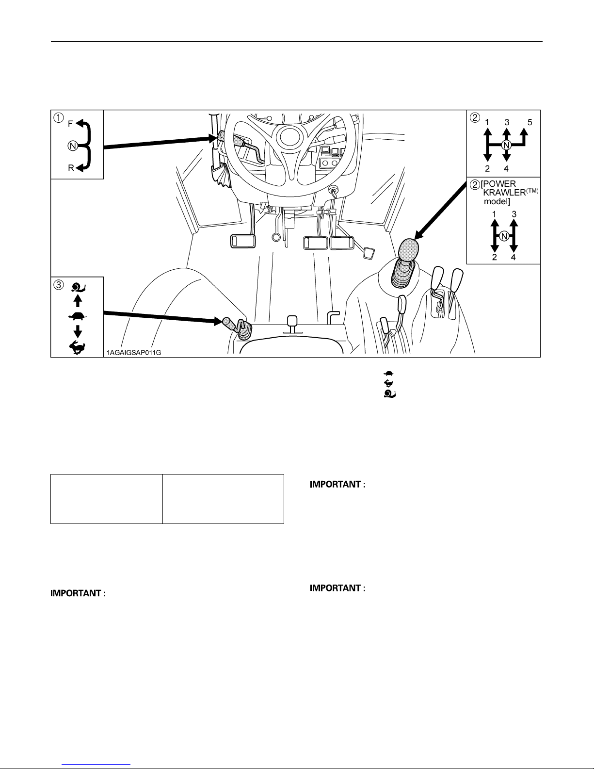
6. Selecting the Travel Speed.
25OPERATING THE TRACTOR
(1) Hydraulic - shuttle shift lever
(2) Main gear shift lever
(3) Range gear shift lever
(F) "FORWARD
(N) "NEUTRAL POSITION"
(R) "REVERSE"
By combination of using the main gear shift lever, the
range gear shift lever and hydraulic-shuttle shift lever,
forward speeds and reverse speeds shown in the table
below are obtained.
Standard model
POWER KRAWLER(TM)
model
15 forward speeds
15 reverse speeds
12 forward speeds
12 reverse speeds
BMain Gear Shift Lever
The main gear shift is fully synchronized to shift without
stopping.
A The main gear shift may be shifted between speeds
on-the-go, but the clutch must be depressed.
"LOW"
"HIGH"
"CREEP"
BRange Gear Shift Lever
The range gear shift can only be shifted when the tractor
is completely stopped and the clutch is depressed.
A To avoid transmission damage, depress clutch pedal
and stop the tractor before shifting between ranges.
BHydraulic-Shuttle Shift Lever
Raise up and shift the shuttle shift lever forward to obtain
forward speeds and shift back to obtain reverse speeds.
This shifting does not require clutch operation.
A The hydraulic-shuttle shift lever may be shifted while
the tractor is moving slowly.
Page 47

OPERATING THE TRACTOR26
BCreep Speed
Shift the range gear shift lever to to obtain low
speeds.
This shifting requires clutch operation.
(1) Range gear shift lever ...Creep ON
C Creep speed should be used only when doing one
of the following jobs:
1. Deep rotary-tilling and harrowing
2. Planting
3. Turf application
C Creep speed can not be used for any of the
followings:
1. Pulling a trailer
2. Front-loader operation
3. Front-blade operation
4. Earth-moving
5. Entering and leaving a field
6. Loading onto and unloading from a truck
B4WD / Bi-speed Turn Switch
To avoid personal injury:
A Do not engage the front wheel drive when
traveling at road speed.
A When driving on icy, wet, or loose surfaces,
make sure the tractor is correctly ballasted to
avoid skidding and loss of steering control.
Operate at reduced speed and engage front
wheel drive.
A 4WD model tractor is equipped with 4 wheel
braking and appropriate care should be taken
during hard braking.
A An accident may occur if the tractor is
suddenly braked, such as by heavy towed
loads shifting forward or loss of control.
A The braking characteristics are different
between two and four wheel drive tractor
models. Be aware of the difference and use
carefully.
A Do not use "Bi-speed Turn" at high speed.
A "Bi-speed Turn" enables short and fast turns,
therefore, become familiar with its performance
before operating in close or confined areas.
A Do not use the Bi-speed turn when operating
the front end loader.
When this switch is pressed;
The front wheel drive (4WD) is engaged.
The 4WD indicator comes on when the system is in
4WD mode.
Press the switch again;
The Bi-speed turn system activates.
The indicator within the switch and 4WD indicator and
Bi-speed turn indicator come on when the system is in
Bi-speed turn mode.
To avoid personal injury:
A When you leave the tractor, be sure to apply the
parking brake and stop the engine.
A IN APPLYING THE BRAKES:
A The torque of the wheel axle is extremely
high while creep speed is being used. Be
sure to step down on the clutch pedal
completely before applying the brakes, or
they will not work
A When starting to operate the tractor, be sure
to release the parking brakes.
Misuse of the brakes may cause damage to
the transmission and is therefore not
acceptable to KUBOTA for coverage under
the warranty.
A Press the clutch pedal completely down and stop the
tractor's motion before shifting the range gear shift
lever.
Press the switch one more time;
The drive system returns to 2WD mode.
All the indicators go off when the system is in 2WD
mode. (While the brake pedal is stepped on or the
parking brake is applied, however, the 4WD braking
system is working and the 4WD indicator stays on.)
Page 48

(1) 4WD/Bi-speed Turn switch
with indicator
(2) 4WD indicator
(3) Bi-speed turn indicator
(A) 4WD "ON"
(B) Bi-speed turn "ON"
(C) 2WD (Switch "OFF")
A This switch can be operated when the tractor is on the
go or at rest without depressing the clutch.
A Bi-speed turn system works when you press the
"4WD/Bi-speed turn switch" twice from "2WD" mode
(once from "4WD" mode) and the turning angle of the
front tires has become large.
Bi-speed turn makes the front tire speed about twice
faster than the standard 4WD front tire speed.
27OPERATING THE TRACTOR
7. Accelerate the Engine.
BHand Throttle Lever
Pulling the throttle lever back increases engine speed,
and pushing it forward decreases engine speed.
BFoot Throttle
Use the foot throttle when traveling on the road. Press
down on it for higher speed. The foot throttle is interlocked
with the hand throttle lever; when using the foot throttle,
keep the hand throttle lever in low idling position.
C Front wheel drive is effective for the following
jobs:
1. When greater pulling force is needed, such as working
in a wet field, when pulling a trailer, disking or
harrowing.
2. When working in sandy soil.
3. When working on a hard soil where a rotary tiller might
push the tractor forward.
4. For increased braking at reduced speed.
C Bi-speed turn use is effective for the following
jobs:
1. Turning at the end of rows. (planting, cultivating,
harrowing.)
2. Increasing maneuverability when working in tight
spaces.
A Tires will wear quickly if the front wheel drive is
engaged on paved roads.
(1) Hand throttle lever
(2) Foot throttle
(A) "INCREASE"
(B) "DECREASE"
8. Unlock the Parking Brake and Slowly
Release the Clutch.
BParking Brake Lever
To release the parking brake, depress the brake pedal,
push the release button and push the parking brake lever
forward.
(1) Parking brake lever
(2) Release button
(A) "RELEASE"
Page 49

OPERATING THE TRACTOR28
A The parking brake indicator light on the Easy
Checker(TM) will turn off when the parking brake is
unlocked.
A Do not attempt to put the tractor in motion before the
parking brake indicator light turns off.
A If the tractor is operated with the parking brake set, the
parking brake might be damaged.
STOPPING
BStopping
1. Slow down the engine.
2. Step on the clutch and brake pedal.
3. After the tractor has stopped, disengage the PTO,
lower the implement to the ground, shift the
transmission to neutral, release the clutch pedal, and
set the parking brake.
CHECK DURING DRIVING
BImmediately Stop the Engine if:
A The engine suddenly slows down or accelerates,
A Unusual noises are suddenly heard,
A Exhaust fumes suddenly become very dark,
Engine oil pressure
If the oil pressure in the engine goes below the
prescribed level, the warning lamp in the Easy
Checker(TM) will come on.
If this should happen during operation, and it does not
go off when the engine is accelerated to more than
1000 rpm, check level of engine oil.
(See "Checking Engine Oil Level" in "DAILY CHECK"
in "PERIODIC SERVICE" section.)
Fuel level
If the fuel in the tank goes below the prescribed level,
the warning lamp in the Easy Checker(TM) will come
on. (less than 12 L)
If this should happen during operation, refuel as soon
as possible.
(See "Checking and Refueling" in "DAILY CHECK" in
"PERIODIC SERVICE" section.)
Air cleaner
If the air cleaner is clogged, the warning lamp in the
Easy Checker(TM) will come on.
If this should happen during operation, clean the air
cleaner element.
(See "Cleaning Air Cleaner Primary Element" in
"EVERY 100 HOURS" in "PERIODIC SERVICE"
section.)
BEasy Checker(TM)
If the warning lamps in the Easy Checker(TM) come on
during operation, immediately stop the engine, and find
the cause as shown below.
Never operate the tractor while Easy Checker(TM) lamp is
on.
(1) Easy Checker(TM)
Electrical charge
If the alternator is not charging the battery, the Easy
Checker(TM) will come on.
If this should happen during operation, check the
electrical charging system or consult your local
KUBOTA Dealer.
A For checking and servicing of your tractor, consult
your local KUBOTA Dealer for instructions.
Page 50

29OPERATING THE TRACTOR
BFuel Gauge
When the key switch is on, the fuel gauge indicates the
fuel level.
Be careful not to empty the fuel tank. Otherwise air may
enter the fuel system.
Should this happen, the system should be bled (See
"Bleeding Fuel System" in "SERVICE AS REQUIRED" in
"PERIODIC SERVICE" section.)
(1) Fuel gauge (A) "FULL"
(B) "EMPTY"
BCoolant Temperature Gauge
To avoid personal injury:
A Do not remove radiator cap until coolant
temperature is well below its boiling point.
Then loosen cap slightly to the stop to relieve
any pressure before removing cap completely.
1. With the key switch at "ON", this gauge indicates the
temperature of the coolant. "C" for "cold" and "H" for
"hot."
2. If the indicator reaches the "H" position (red zone),
engine coolant is overheated. Check the tractor by
referring to "TROUBLESHOOTING" section.
(1) Coolant temperature gauge
BTachometer
The tachometer indicates the engine speed on the dial.
(1) Engine revolution
Page 51

30 OPERATING THE TRACTOR
PTO RPM / TRAVEL SPEED MONITOR
BChanging Display Mode
1. The LCD monitor gives two different display modes: "Traveling speed and Hour meter" and "Traveling speed and PTO
speed". Each time the PTO/Hour meter select switch is pressed, the mode is switched to the changing display.
2. To switch between "mph" and "km/h" for the traveling speed, use the Traveling speed select switch.
3. The PTO clutch control switch works for the following automatic display modes.
1) PTO clutch control switch ON: Traveling speed and PTO speed are displayed.
2) PTO clutch control switch OFF: Traveling speed and Hour meter are displayed.
(1) LCD monitor
(2) Hour Meter indication
(3) PTO Indication
(4) PTO / Hour Meter Select Switch
(5) Traveling Speed Select Switch
Page 52

31OPERATING THE TRACTOR
Display mode switching
[Hour meter mode] and [PTO
speed mode]
1
Display mode switching
[km/h] and [mph]
2
Hour meter mode A Traveling speed and total operating hours
are displayed.
A The hour meter indicates in five digits the
hours the tractor has been used; the last
digit indicates 1/10 of an hour.
PTO speed mode
km/h (Traveling speed)
mph (Traveling speed)
A Traveling speed and PTO speed are
displayed.
A When the PTO clutch control switch is in
"OFF" position, "OFF" is displayed.
A See "PTO Speed Display Mode Switching"
in "PTO RPM / TRAVEL SPEED
MONITOR" in "OPERATING THE
TRACTOR" section.
PTO clutch control switch PTO OFF (Hour meter mode) A Traveling speed and total operating hours
are displayed.
A The hour meter indicates in five digits the
hours the tractor has been used; the last
digit indicates 1/10 of an hour.
A When the PTO / Hour meter select switch is
pressed in this state, "OFF" is displayed.
3
A The travel speed displayed when the wheels slip under traction is different from the actual one.
A In cold weather the LCD monitor response will normally be slower and the visibility be less, than in warmer weather.
PTO ON (PTO speed mode) A Traveling speed and PTO speed are
displayed.
A When the PTO / Hour meter select switch is
pressed in this state, the display mode
switches to hour meter mode.
Page 53

32 OPERATING THE TRACTOR
BPTO Speed Display Mode Switching
[with 540/540E rpm model]
The PTO speed display mode has been factory-set at Code 1. Do not attempt to change the code. Otherwise the correct
PTO speed will not be displayed in the LCD monitor.
(NOTE: The current code can be checked in the following procedure.)
[with 540/1000 rpm model]
The PTO speed display mode has been factory-set at Code 2. Do not attempt to change the code. Otherwise the correct
PTO speed will not be displayed in the LCD monitor.
(NOTE: The current code can be checked in the following procedure.)
C Switching procedure
Page 54

33OPERATING THE TRACTOR
BEntering the Travel Speed Coefficient
When optional different-diameter tires are fitted on the machine, the travel speed display mode must be changed.
Otherwise the travel speed will not get correctly displayed. Such mode switching is also needed when the original tires are
back on the machine.
C How to enter the tire circumference
Example: Entering 4455 mm.
Page 55

OPERATING THE TRACTOR34
PARKING
BParking
To avoid personal injury:
BEFORE DISMOUNTING TRACTOR
A ALWAYS SET PARKING BRAKE AND LOWER
ALL IMPLEMENTS TO THE GROUND.
Leaving transmission in gear with the engine
stopped will not prevent the tractor from
accidental rolling.
A STOP THE ENGINE AND REMOVE THE KEY.
1. Before getting off the tractor, disengage the PTO,
lower all implements, place all control levers in their
neutral positions, pull the parking brake lever rearward
to park, stop the engine and remove the key.
2. If it is necessary to park on an incline, be sure to chock
the wheels to prevent accidental rolling of the
machine.
OPERATING TECHNIQUES
BDifferential Lock
To avoid personal injury due to loss of steering
control:
A Do not operate the tractor at high speed with
differential lock engaged.
A Do not attempt to turn with the differential lock
engaged.
A Be sure to release the differential lock before
making a turn in field conditions.
If one of the rear wheels should slip, step on the
differential lock pedal. Both wheels will turn together, then
reduce slippage.
Differential lock is maintained only while the pedal is
depressed.
(1) Parking brake lever
(2) Release button
(A) "PULL"
(1) Differential lock pedal (A) Press to "ENGAGE"
(B) Release to "DISENGAGE"
A When using the differential lock, always slow the
engine down.
A To prevent damage to power train, do not engage
differential lock when one wheel is spinning and the
other is completely stopped.
A If the differential lock cannot be released, step lightly
on the brake pedals alternately.
Page 56

35OPERATING THE TRACTOR
BOperating the Tractor on a Road
To avoid personal injury:
A To help assure straight line stops when driving
at transport speeds, lock the brake pedals
together. Uneven braking at road speeds could
cause the tractor to roll-over.
A When traveling on road with 3-point hitch
mounted implement attached, be sure to have
sufficient front weight on the tractor to
maintain steering ability.
Observe all local traffic and safety regulations.
Use the registration plate.
BOperating on Slopes and Rough Terrain
To avoid personal injury:
A Always back up when going up a steep slope.
Driving forward could cause the tractor to tip
over backward. Stay off hills and slopes too
steep for safe operation.
A Avoid changing gears when climbing or
descending a slope.
A If operating on a slope, never disengage the
clutch or shift levers to neutral. Doing so could
cause loss of control.
A Do not drive the tractor close to the edges of
ditches or banks which may collapse under the
weight of the tractor. Especially when the
ground is loose or wet.
1. Be sure wheel tread is adjusted to provide maximum
stability.
(See "WHEEL ADJUSTMENT" in "TIRES, WHEELS
AND BALLAST" section.)
2. Slow down for slopes, rough ground, and sharp turns,
especially when transporting heavy, rear mounted
equipment.
3. Before descending a slope, shift to a gear low enough
to control speed without using brakes.
(1) Registration plate
BTransport the Tractor Safely
1. The tractor, if damaged, must be carried on a truck.
Secure the tractor tightly with ropes.
2. Follow the instruction below when towing the tractor:
Otherwise, the tractor’s powertrain may get damaged.
A Set the all shift levers to "NEUTRAL" position.
A If possible, start engine and select 2WD, if creep
speed is fitted ensure that it is disengaged.
A Tow the tractor using its front hitch or drawbar.
A Never tow faster than "10 km/h (6.2 mph)".
BDirections for Use of Power Steering
1. Power steering is activated only while the engine is
running. Slow engine speeds make the steering a little
heavier. While the engine is stopped, the tractor
functions in the same manner as tractors without
power steering.
2. When the steering wheel is turned all the way to the
stop, the relief valve is activated. Do not hold the
steering wheel in this position for a long period of time.
3. Avoid turning the steering wheel while the tractor is
stopped, or tires may wear out sooner.
4. The power steering mechanism makes the steering
easier. Be careful when driving on a road at high
speeds.
Page 57

OPERATING THE TRACTOR36
BTrailer Electrical Outlet
A trailer electrical outlet is supplied for use with trailer or
implement.
(1) Trailer electrical outlet
BHydraulic Brake for Trailer
(if equipped)
The trailer brake is worked when using the tractor's brake
pedals. It uses the pressure from the main hydraulic
circuit. The braking force while towing is proportional to
the force applied on the tractor pedals.
It is most useful when towing very heavy loads, this device
considerably increases braking efficiency and safety.
C Function of each terminals in trailer electrical
outlet
Terminal Function
(1) Turn signal light (LH)
(2) ---
(3) Ground
(1) Trailer hydraulic brake outlet
(4) Turn signal light (RH)
Tail light
(5)
(6) Brake stop light
(7) Registration plate light
Sidemarker light
Parking light
Page 58

PTO
37PTO
PTO OPERATION
To avoid personal injury:
A Disengage PTO, stop engine, and allow all
rotating components to come to a complete
stop before connecting, disconnecting,
adjusting, or cleaning any PTO driven
equipment.
BPTO Clutch Control Switch
The PTO clutch control switch engages or disengages the
PTO clutch which gives the PTO independent control.
Turn the switch to "ON" to engage the PTO clutch. Turn
the switch to "OFF" to disengage the PTO clutch.
(1) PTO clutch control switch "ON" "OFF"
C PTO Clutch Control Switch
To turn ON
While pushing the switch, turn clockwise to the " "
position and release your hand. (In the ON position,
switch slightly rises itself.)
To Turn OFF
Tap on top of the switch, and the switch will return to the
OFF position.
(A) "PUSH"
A To avoid shock loads to the PTO, reduce engine
speed when engaging the PTO, then open the throttle
to the recommended speed.
A Tractor engine will not start if PTO clutch control switch
is in the engaged "ON" position.
A If the PTO system is engaged and you stand up from
the seat, the warning buzzer will whistle for about 10
seconds after standing up.
This is because the tractor is equipped with "Operator
Presence Control System".
C PTO Clutch Indicator
The PTO clutch indicator turns on while PTO clutch
control switch is in "ON" (Engage) position.
(1) PTO clutch indicator
Page 59

PTO38
PTO 540 / 540E rpm model
BPTO Gear Shift Lever
To avoid personal injury:
A Be sure to observe the PTO shaft speed
prescribed for the individual implements. It is
extremely dangerous to run an implement at
high speed that is meant to be operated at low
speed. Use only when this higher rpm is
specifically recommended by the implement
manufacturer.
The PTO gear shift lever can be set to either 540 rpm or
540E rpm positions.
Move this lever to either position with the PTO clutch
control switch set to "OFF".
PTO 540 / 1000 rpm model (if equipped)
BPTO Gear Shift Lever
To avoid personal injury:
A Be sure to observe the PTO shaft speed
prescribed for the individual implements. It is
extremely dangerous to run an implement at
high speed that is meant to be operated at low
speed. Use only when this higher rpm is
specifically recommended by the implement
manufacturer.
The PTO gear shift lever can be set to either 540 rpm or
1000 rpm positions.
Move this lever to either position with the PTO clutch
control switch set to "OFF".
(1) PTO gear shift lever (A) 540 rpm
(B) 540E rpm
A When light load, select the "540E" position for
economical operation.
(1) PTO gear shift lever (A) 540 rpm
(B) 1000 rpm
A For maximum PTO shaft speeds of various
implements, see the implement Operator's Manual.
Page 60

39PTO
BLCD Monitor Message
1. The PTO rpm can be checked in the LCD monitor.
(See "PTO RPM / TRAVEL SPEED MONITOR" in
"OPERATING THE TRACTOR" section.)
2. When the PTO system gets engaged (ON), the
indicator lights up.
(1) LCD monitor
(2) PTO clutch indicator
BPTO Shaft Cover and Shaft Cap
Keep the PTO shaft cover in place at all times. Replace
the PTO shaft cap when the PTO is not in use. Before
connecting or disconnecting a drive shaft to PTO shaft, be
sure engine is "OFF".
A The PTO rpm indicator functions well when the engine
PTO is selected. But it fails to function when the
ground PTO is selected.
(1) PTO shaft cover
(2) PTO shaft cap
A The universal joint of the PTO drive shaft is technically
limited in its moving angle. Refer to the PTO Drive
Shaft Instructions for proper use.
Page 61

PTO40
GROUND PTO OPERATION
(if equipped)
To avoid personal injury:
A Do not shift the ground/engine PTO select lever
while in operation. If the select lever is returned
to the neutral position, the power to the wheels
of a power trailer or any similar implement is
cut off, which is very dangerous.
A The ground PTO revolution is made in
proportion to the tractor speed. To avoid too
high speeds of this shaft, make sure the
ground/engine PTO select lever is at the neutral
position when the tractor travels at high speed.
To avoid personal injury:
A When working with a power trailer on a slope or
rugged road, follow the allowable load capacity
specified in the Operator's Manual and avoid
travelling at high speed for added safety.
A The ground PTO revolution is made in
proportion to the tractor speed. In backing the
tractor, this shaft turns in the opposite
direction.
BGround / Engine PTO Select Lever
This lever provides for the following two different PTO
speeds.
1. Ground PTO:
The PTO shaft revolution in proportion to the tractor
speed is achieved, which is suited for power trailers,
planters and other tractor speed-interlocked
implements. The PTO shaft turning direction is
clockwise when viewed from the back of the tractor.
2. Engine PTO:
The PTO shaft rpm in proportion to the engine speed
is achieved, which is suited for mowers, harvesters
and other general implements. (For details, see "PTO
OPERATION" in the previous page.)
C Operation
1. Step on the clutch pedal and the brake pedal at once
to stop the tractor.
2. Set the PTO clutch control switch to the "OFF"
position.
3. To select "Ground PTO", pull up the lever. In this case,
the PTO clutch indicator on the meter panel lights up.
(1) Ground / Engine PTO select lever (A) "GROUND PTO"
(N) "NEUTRAL"
(B) "ENGINE PTO"
A When you do not want a coupled implement to turn in
the opposite direction in backing the tractor, set the
ground/engine PTO select lever to the neutral position
in advance. (The PTO shaft does not stop even if the
PTO clutch control switch is set to the "OFF" position.)
Page 62

A When neither "Ground PTO" nor "Engine PTO" is
used, set the ground/engine PTO select lever to the
neutral position. If a power trailer is used with "Engine
PTO", the PTO clutch may get damaged.
A Stop the tractor first before using the ground/engine
PTO select lever. Do not shift this lever while the
tractor is running.
A When an implement (example: power trailer) is heavy
in traction force, do not operate the tractor at creep
speed (if equipped).
C Ground PTO revolutions (PTO shaft revolutions
per wheel turn)
The PTO shaft revolutions per wheel turn, with the PTO
gear shift lever being selected, are as shown below.
PTO gear shift lever
540 rpm 540E rpm 1000 rpm
41PTO
M7040N
M8540N
M6040
M7040
M8540
M9540
A When a power trailer or other tractor speed-
interlocked implement is coupled, employ a specific
model that suits the tractor speed. If an unmatched
implement is connected, the tractor or the implement
may get in trouble.
A Before starting the job, check the PTO gear shift lever
position too.
A 540E rpm or 1000 rpm use is recommended for the
ground PTO implement. For details on matching and
other requirements, consult with your local KUBOTA
Dealer.
8.94 10.56 14.47
8.94 10.56 14.47
9.87 13.22 15.57
Page 63

42 THREE-POINT HITCH & DRAWBAR
THREE-POINT HITCH & DRAWBAR
(1) Top link
(2) Lifting rod (Left)
(3) Stabilizer
(4) Lower link
(5) Lifting rod (Right)
(6) Drawbar (if equipped)
(7) High-hitch (if equipped)
(8) Piton-fix (if equipped)
A The equipped parts change with specifications for
each country.
Page 64

43THREE-POINT HITCH & DRAWBAR
3-POINT HITCH
1. Make preparations for attaching
implement.
BCategory 1 & 2
The standard tractor has both category 1 & 2.
Category 1 type is standard and assemble all parts shown
as below.
To change from category 1 to category 2.
1. Remove adjusting collar from the lower link.
2. Add side collar onto both the lower links.
3. Remove adjusting collar from the rear top link pin.
4. Use the correct rear top link pin for category 2.
BSelecting the holes of Lower Links
There are two holes in the lower links. For most
operations the lifting rods should be attached to the (B)
hole.
(1) Lower link
(2) Lifting rod
(3) Split pin
A The lifting rods may be attached to (A) for greater
lifting force.
A Install the thrust collar in the outside of the lower link.
A Tighten the nut by hand and fix the nut with the cotter
pin.
(4) Nut
(5) Lift rod pin
(6) Thrust collar
holes: (A), (B)
(1) Lower link
(2) Top link
(3) Collar, lower link (1)
(4) Top link rear pin (1)
BSelecting the Top Link Mounting Holes
Select the proper set of holes by referring to the
"Hydraulic Control Unit Use Reference Chart" in Hydraulic
Unit section.
If the hydraulic unit is set for draft control, draft response
is more sensitive when an implement is connected to the
lower set of top link mounting holes. If draft control is not
required, it is recommended to use the top set (1).
(5) Collar, top link (1)
(6) Top link rear pin (2)
(7) Collar, side (2)
Page 65

THREE-POINT HITCH & DRAWBAR44
BDrawbar
Remove the drawbar if a close mounted implement is
attached.
BLifting Rod (Right)
2. Attaching and detaching implements
To avoid personal injury:
A Be sure to stop the engine.
A Do not stand between tractor and implement
unless parking brake is applied.
A Before attaching or detaching implement,
locate the tractor and implement on a firm level
surface.
A Whenever an implement or other attachment is
connected to the tractor 3-point hitch, check
full range of operation for interference, binding
or PTO separation.
A Do not exceed maximum allowable length of
either lifting rod, or the lifting rod will come
apart and the 3-point equipment may fall.
BLifting Rod (Left)
By turning the rod itself, the lifting rod varies its length.
When extending the rod, do not exceed the groove on the
rod thread.
To avoid personal injury:
A Do not extend lifting rod beyond the groove on
the thread rod.
1. To adjust the length of the lifting rod, lift the adjusting
handle and turn to desired length.
2. After adjusting, the lifting rod adjusting handle must be
returned and stored in the fore and aft position.
3. When extending the rod using adjusting handle, do not
exceed the groove on the rod thread.
(1) Lifting rod
(2) Adjusting handle
(A) "GROOVE"
(1) Lifting rod (A) "GROOVE"
(1) Adjusting handle
(2) Lock pin
(A) "LOCK POSITION"
(B) "UNLOCK POSITION"
Page 66

45THREE-POINT HITCH & DRAWBAR
BTop Link
1. Adjust the angle of the implement to the desired
position by shortening or lengthening the top link.
2. The proper length of the top link varies according to
the type of implement being used.
(1) Top link (A) "Length of the screw"
A The length of the screw at both ends of the top link
must be the same always.
BStabilizer
Adjust the stabilizers to control horizontal sway of the
implement.
Turn the outer tube until one of its holes aligns with the
inner tube hole. Insert the set-pin to lock the outer and
inner tubes.
When readjusting, make sure both the stabilizers are
equal in overall length.
(1) Outer tube
(2) Inner tube
(3) Set-pin
(4) Hole
(1) Set-pin
(2) Hairpin cotter
Page 67

THREE-POINT HITCH & DRAWBAR46
DRAWBAR
[if equipped]
To avoid personal injury:
A Never pull from the top link, the rear axle or any
point above the drawbar. Doing so could cause
the tractor to tip over rearward causing
personal injury or death.
A The drawbar load is referred to "IMPLEMENT
LIMITATIONS" section.
BSwing Drawbar
The drawbar can be used in three different ways as
illustrated below. Assemble it correctly with locating pins.
(1) Drawbar
(2) Locating pin
HIGH-HITCH
[if equiped]
(1) Drawbar
(2) Pivot pin
(3) Locating pin
To avoid personal injury:
A Never pull from the top link, the rear axle or any
point above the hitch. Doing so could cause the
tractor to tip over rearward causing personal
injury or death.
A The high-hitch load is referred to "IMPLEMENT
LIMITATIONS" section.
BHigh-Hitch
The high-hitch can be adjusted depending on an
attachment to pull behind. The high-hitch may get in the
way when connecting the universal joint. In such case,
either set the high-hitch to its uppermost position or
remove it.
Page 68

47THREE-POINT HITCH & DRAWBAR
C Adjusting the high-hitch level
(B type)
1. Turn the handle upward to unlock them. Move the
high-hitch bracket up and down to change the hitch
height.
2. Align the lock pin with the lock hole. Return the handle
horizontal to lock them.
(1) Normal
(2) Auto
(3) CUNA C
(4) CUNA D2
C Adjusting the high-hitch level
(A type)
1. Tilt up the lock lever to unlock them. Move the highhitch bracket up and down to change the hitch height.
2. Align the lock pin with the lock hole. Return the lock
lever downward to lock them.
(1) High-hitch
(2) Lock lever
(3) Lock pin
(4) Lock hole
(A) "UN-LOCK"
(B) "LOCK"
(1) High-hitch
(2) Handle
(3) Lock pin
(4) Lock hole
(A) "UN-LOCK"
(B) "LOCK"
BHigh-hitch with Automatic Trailer
Coupling
C COUPLING UP
1. Lift the operating handle upwards as far as it will go
until it blocks.
The coupling pin is raised and the trigger lever is
visible.
(1) Operating handle
(2) Coupling pin
(3) Trigger lever
(4) Security pin
Page 69

THREE-POINT HITCH & DRAWBAR48
2. Slowly reverse the tractor: the drawbar eye on the
trailer must fully penetrate into the hitch assembly until
the trigger lever is released, whereupon the shunt
force produced will cause the immediate insertion of
the coupling pin as well as the automatic retraction of
the security pin.
(1) Lock handle
PITON-FIX
(1) Drawbar eye
(2) Hitch assembly
(3) Operating handle
(4) Coupling pin
(5) Trigger lever
(6) Security pin
C UNCOUPLING
1. Lift the operating handle until it locks into position.
2. Travel forward the tractor until the drawbar eye is
disengaged.
(1) Operating handle
3. For safety reasons, it is hereby recommended that the
drawbar coupling is kept locked at all times.
To lock the drawbar coupling, act on the lock handle
rotating it in the direction of the arrow, as illustrated.
To avoid personal injury:
A Never pull from the top link, the rear axle or any
point above the piton-fix. Doing so could cause
the tractor to tip over rearward causing
personal injury or death.
A The piton-fix load is referred to "IMPLEMENT
LIMITATIONS" section.
BPiton-Fix
In using the piton-fix to pull an attachment, lock the
retainer with pin.
(1) Piton-fix
(2) Retainer
(3) Pin
(4) Lynch pin
(A) "LOCK"
(B) "UNLOCK"
Page 70

HYDRAULIC UNIT
The standard tractor has following hydraulic control
systems as shown below. Therefore, use the most
appropriate system for the implement you are using.
C 3-Point Hitch Control System
1. Position Control
2. Draft Control
3. Mixed Control
4. Float Control
C Remote Hydraulic Control System
A Do not operate until the engine is warmed up. If
operation is attempted when the engine is still cold, the
hydraulic system may be damaged.
A If noises are heard when implement is lifting after the
hydraulic control lever has been activated, the
hydraulic mechanism is not adjusted properly. Unless
corrected, the unit will be damaged. Contact your
KUBOTA Dealer for adjustment.
3-POINT HITCH CONTROL SYSTEM
To avoid personal injury:
A Before using the 3-point hitch controls, ensure
that no person or object is in the area of the
implement or 3-point hitch. Do not stand on or
near the implement or between the implement
and tractor when operating the 3-point hitch
controls.
49HYDRAULIC UNIT
(1) Position control lever
(2) Draft control lever
(A) "FLOAT"
(B) "DOWN"
(C) "UP"
BDraft Control
This will control the pull of the 3-point implement. As the
load on the 3-point hitch changes due to various soil
conditions, the draft control system automatically
responds to these changes by either raising or lowering
the implement slightly to maintain a constant pull.
Place the position control lever in the lowest position and
set the implement pull with the draft control lever.
BPosition Control
This will control the working depth of 3-point hitch
mounted implement regardless of the amount of pull
required.
(1) Draft control lever
(2) Position control lever
(A) "SENSITIVE"
(B) "INSENSITIVE"
(C) "FLOAT"
Page 71

HYDRAULIC UNIT50
BMixed Control
In draft control, when draft decreases, the implement
automatically lowers to increase draft. However, the
implement sometimes lowers too much. To limit the
degree, the implement can be lowered, set the position
control lever at the lowest working depth desired for the
implement. Lower the draft control lever to the point where
the implement is at the desired depth.
This stops the implement from going too deep and
causing loss of traction and ground speed.
(1) 3-Point hitch lowering speed lever (A) "FAST"
(B) "SLOW"
(C) "LOCK"
REMOTE HYDRAULIC CONTROL SYSTEM
The hydraulic auxiliary control valves can be installed up
to triple segments.
It is not possible to use triple segments with flow control
valve.
(1) Ground surface
(2) Implement penetration limit
(3) Light soil
BFloat Control
Place both the draft control lever and the position control
lever in the float position to make the lower links move
freely along with the ground conditions.
B3-point Hitch Lowering Speed
To avoid personal injury:
A Fast lowering speed may cause damage or
injury. Lowering speed of implement should be
adjusted to two or more seconds.
The lowering speed of the 3-point hitch can be controlled
by adjusting the 3-point hitch lowering speed lever.
BRemote Control Valve
There are two types of remote valves available for these
models.
A Double acting valve with detents and self cancelling:
This valve may be placed in the detent mode. The
lever will stay in this position until the pressure reaches
a predetermined level or a cylinder reaches the end of
its stroke. Then it will automatically return to neutral.
A Single/double acting valve:
This valve can be utilized as single or double acting
valve by adjusting the auxiliary control valve selector
knob located on the valve.
1) Turn the auxiliary control valve selector knob
clockwise all the way to utilize as single acting
valve.
2) Turn the auxiliary control valve selector knob
anticlockwise all the way to utilize as double
acting valve.
Page 72

P ress ure
Retu rni ng
Double-acting Single-acting
51HYDRAULIC UNIT
(1) Single / double acting valve
(2) Auxiliary control valve
selector knob
(A) Double acting
(B) Single acting
BRemote Control Valve Lever
The remote control valve lever directs pressurized oil flow
to the implement hydraulic system.
Lever (1)
Lever position
YXYX
[A] out in - -
Port
[B] in out in out
Lever position
Lever (2)
Z(detent) Y X Z(detent)
[C] out in
Port
[D] in out
A Do not hold the lever in the "REARWARD" or
"FORWARD" position once the remote cylinder has
reached the end of the stroke, as this will cause oil to
flow through the relief valve. Forcing oil through the
relief valve for extended periods will overheat the oil.
A When using the tractor hydraulic system to power front
loader, do not operate boom and bucket cylinders
simultaneously.
A Connect the pressure of load side of implement
cylinders to ports [B] or [D] which have built in load
check valve to prevent leak down.
(1)
Remote control valve lever with Single / double acting valve
(2)
Remote control valve lever with Double acting valve / Detents
and self cancelling
Page 73

HYDRAULIC UNIT52
BRemote Control Valve Coupler
Connecting and Disconnecting
To avoid personal injury:
A Stop the engine and relieve pressure before
connecting or disconnecting lines.
A Do not use your hand to check for leaks.
C Connecting
1. Clean both couplers.
2. Remove dust plugs.
3. Insert the implement coupler to the tractor hydraulic
coupler.
4. Pull the implement coupler slightly to make sure
couplers are firmly connected.
C Disconnecting
1. Lower the implement first to the ground to release
hydraulic pressure in the hoses.
2. Clean the couplers.
3. Relieve pressure by moving hydraulic control levers
with engine shut off. Pull the hose straight from the
hydraulic coupler to release it.
4. Clean oil and dust from the coupler, then replace the
dust plugs.
A Your local KUBOTA Dealer can supply parts to adapt
couplers to hydraulic hoses.
Page 74
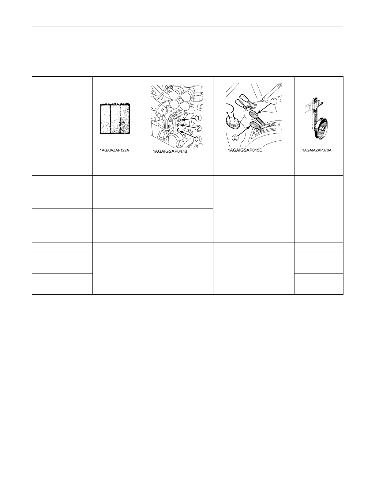
53HYDRAULIC UNIT
BHydraulic Control Unit Use Reference Chart
In order to handle the hydraulics properly, the operator must be familiar with the following.
Though this information may not be applicable to all types of implements and soil conditions, it is useful for general
conditions.
Implement
Soil condition Top link mounting holes
Light soil
Moldboard plow
Disc plow --- 2 or 3
Harrower (spike,
springtooth, disc type)
Sub-soiler...............
Weeder, ridger........
Earthmover, digger,
scraper, manure fork, rear
carrier......
Mower (mid- and rearmount type) Hayrake,
tedder......
Medium soil
Heavy soil
--- 2
--- 1
3
2 or 3
2
(1) Position control lever
(2) Draft control lever
Draft and Mixed control
(Place the draft control lever
to the suitable position and
set the implement pull with
the position control lever.)
Position control
(Hold the draft control lever
at the front most position
during operation.)
Gauge wheel
YES/NO
YES
YES/NO
NO
Page 75

54 TIRES, WHEELS AND BALLAST
TIRES, WHEELS AND BALLAST
TIRES
BDual Tires
To avoid personal injury:
A Do not attempt to mount a tire on a rim. This
should be done by a qualified person with the
proper equipment.
A Always maintain the correct tire pressure.
Do not inflate tires above the recommended
pressure shown in the operator's manual.
A Do not use tires other than those approved by
KUBOTA.
A When optional different-diameter tires are fitted on the
machine, the travel speed display mode must be
changed. Otherwise the travel speed will not get
correctly displayed. Such mode switching is also
needed when the original tires are back on the
machine.
(See "PTO RPM / TRAVEL SPEED MONITOR" in
"OPERATING THE TRACTOR" section.)
Dual tires are not approved.
WHEEL ADJUSTMENT
To avoid personal injury:
A When working on slopes or when working with
trailer, set the wheel tread as wide as practical
for maximum stability.
A Support tractor securely on stands before
removing a wheel.
A Do not work under any hydraulically supported
devices. They can settle, suddenly leak down,
or be accidentally lowered. If necessary to work
under tractor or any machine elements for
servicing or adjustment, securely support them
with stands or suitable blocking beforehand.
A Never operate tractor with a loose rim, wheel,
or axle.
BInflation Pressure
Though the tire pressure is factory-set to the prescribed
level, it naturally drops slowly in the course of time. Thus,
check it everyday and inflate as necessary.
A Maintain the maximum pressure in front tires, if using
a front loader or when equipped with a full load of front
weights.
Tire sizes Inflation Pressure
7.5-16 280 kPa (2.9 kgf/cm )
7.5-18 225 kPa (2.3 kgf/cm )
Front
Rear
250 / 80-16 250 kPa (2.5 kgf/cm )
250 / 80-18 250 kPa (2.5 kgf/cm )
280 / 70R18 196 kPa (2.0 kgf/cm )
12.4R24 160 kPa (1.6 kgf/cm )
320 / 85R28 160 kPa (1.6 kgf/cm )
380 / 70R24 120 kPa (1.2 kgf/cm )
360 / 70R28 140 kPa (1.4 kgf/cm )
380 / 70R28 120 kPa (1.2 kgf/cm )
440 / 65R28 120 kPa (1.2 kgf/cm )
Page 76

BFront Wheels (with four wheel drive)
Front tread width can be adjusted as shown with the
standard equipped tires.
To change the tread width
1. Change the position of the right and left tires, and
tighten the bolts.
2. Adjust the toe-in [2 to 8mm]
See "Adjusting Toe-in" in "EVERY 200 HOURS" in
"PERIODIC SERVICE" section.
280/70R18 1142 mm 1156 mm
250/80-18 1139 mm 1154 mm
55TIRES, WHEELS AND BALLAST
(1) 168 to 196 N-m (17.1 to 20.0 kgf-m)
To avoid personal injury:
A Before jacking up the tractor, park it on a firm
and level ground and chock the rear wheels.
A Fix the front axle to keep it from swinging.
A Select jacks that withstand the machine weight
and set them up as shown below.
7.5-16 --- 1157 mm
7.5-18 1139 mm 1155 mm
250/80-16 1121 mm 1177 mm
A Always attach wheels as shown in the drawing.
A If not attached as illustrated, transmission parts may
be damaged.
A When re-fitting or adjusting a wheel, tighten the bolts
to the following torques then recheck after driving the
tractor 200m (200 yards) and 10 times of shuttle
movement by 5 m (5 yards), and thereafter according
to service interval. (See "MAINTENANCE" section.)
(1) Jack point
Page 77

TIRES, WHEELS AND BALLAST56
BRear Wheels
Rear tread width can be adjusted as shown with the
standard equipped tires.
To change the tread width
1. Remove the wheel rim and / or disk mounting bolts.
2. Change the position of the rim and / or disk (right and
left) to the desired position, and tighten the bolts.
A Always attach wheels as shown in the drawing.
A If not attached as illustrated, transmission parts may
be damaged.
A When re-fitting or adjusting a wheel, tighten the bolts
to the following torques then recheck after driving the
tractor 200m (200 yards) and 10 times of shuttle
movement by 5 m (5 yards), and thereafter according
to service interval. (See "MAINTENANCE" section.)
(1) 260 to 304 N-m (26.5 to 31.0 kgf-m)
(2) 260 to 304 N-m (26.5 to 31.0 kgf-m)
320 / 85R28 --- 1232 mm 1286 mm 1326 mm 1380 mm
380 / 70R28 1060 mm 1154 mm 1266 mm 1348 mm ---
To avoid personal injury:
A Before jacking up the tractor, park it on a firm
and level ground and chock the front wheels.
A Fix the front axle to keep it from swinging.
A Select a jack that withstands the machine
weight and set it up as shown below.
(1) Jack point
Page 78

57TIRES, WHEELS AND BALLAST
BALLAST
To avoid personal injury:
A Additional ballast will be needed for
transporting heavy implements. When the
implement is raised, drive slowly over rough
ground, regardless of how much ballast is
used.
A Do not fill the front wheels with liquid to
maintain steering control.
BFront Ballast
Add weights if needed for stability and improve traction.
Heavy pulling and heavy rear mounted implements tend
to lift front wheels.
Add enough ballast to maintain steering control and
prevent tip over. Remove weight when no longer needed.
C Front End Weights (option)
The front end weights can be attached to the bumper.
See your implement operator's manual for required
number of weights or consult your local KUBOTA Dealer
to use.
BRear Ballast
Add weight to rear wheels if needed to improve traction or
for stability. The amount of rear ballast should be matched
to job and the ballast should be removed when it is not
needed.
The weight should be added to the tractor in the form of
liquid ballast, rear wheel weights or a combination of both.
C Rear Wheel Weights (option)
The rear wheel weights can be attached to the rear wheel.
See your implement operator's manual for required
number of weights or consult your local KUBOTA Dealer
to use.
(1) Front end weights
(2) Bumper
A Do not overload tires.
A Add no more weight than indicated in chart.
A Do not attach the front bumper when the front loader
is attached.
Maximum weight 45 kg x 10 pieces
(1) Rear wheel weights
A Do not overload tires.
A Add no more weight than indicated in chart.
Maximum weight
per wheel
40 kg x 2 pieces
BMaximum Masses
(See "APPENDICES" section.)
Page 79

58 CAB OPERATION
CAB OPERATION
DOOR AND WINDOW
BLocking and Unlocking the Door
From the outside ...... Insert the key into the door lock.
Turn the key clockwise to unlock
the door. To lock the door, turn
the key in the opposite direction.
The key can be removed when it
is in the vertical direction.
From the inside ....... Push down the lock knob to lock
the door.
Pull up the lock knob to unlock
the door.
BOpening the Door
From the outside ...... Unlock the door, and pull the
outer door handle.
(1) Outer door handle
(2) Door lock
(A) "PULL"
(1) Inner door handle
(2) Lock knob
(A) "PULL"
(B) "PUSH" (Lock)
(C) "PULL" (Unlock)
BRear Window
Turn the rear window handle clockwise to the vertical
position and push the handle. The rear window is opened
by the gas spring cylinder.
(1) Rear window handle (A) "OPEN"
(B) "CLOSE"
From the inside ........ Unlock the door and pull the
inner door handle.
Page 80

BSide Window
Pull the side window handle and push the side window to
open the window.
(1) Side window handle
BEmergency Exit
1. Open the right door of the cab if the left door is
blocked, and vice versa in an emergency situation.
2. Exit through rear window if CAB doors are blocked in
an emergency situation.
59CAB OPERATION
(1) Dome light (A) "OFF"
(B) "DOOR"
(C) "ON"
A The battery will discharge if the dome light remains on.
Be sure to check the dome light lens position and/or
door closure.
WORK LIGHT
DOME LIGHT
BDome Light
Sliding the dome light lens will give the following light
condition:
OFF ............... The light does not turn on when the
door is opened.
DOOR ........... The light turns on when the door (LH)
is opened. It turns off when the door
(LH) is closed.
ON ................ The light remains on regardless of the
door position.
To avoid personal injury:
A Do not operate on roads with work lights on.
Work lights may blind or confuse operators of
oncoming vehicles.
BWork Light Switch
Turn on the key switch and press the top half of the work
light switch. The work light and the switch's indicator light
up. Press the bottom half of the work light switch to turn
off the light and indicator.
(1) Front work light switch
(2) Rear work light switch
(A) Indicator for work lights
Page 81

CAB OPERATION60
BFront Work Light
(1) Front work light
BRear Work Light
BRear Wiper / Washer Switch (if equipped)
1. Turn on the key switch and press the top half of the
wiper switch to the first step, and the wiper is activated.
When the switch is pressed further to the second step,
washer liquid jets out.
The jetting continues while the switch is pressed and
the wiper is activated continuously.
2. Press the bottom half of the wiper / washer switch,
washer liquid only jets out.
(1) Front wiper / washer switch
(2) Rear wiper / washer switch (if equipped)
(1) Rear work light
WIPER
BFront Wiper / Washer Switch
1. Turn on the key switch and press the top half of the
wiper switch to the first step, the wiper is activated.
When the switch is pressed further to the second step,
washer liquid jets out.
The jetting continues while the switch is pressed and
the wiper is activated continuously.
2. Press the bottom half to the first step, the wiper is
activated at regular intervals.
When the switch is pressed further to the second step,
washer liquid jets out and the wiper is activated at
regular intervals.
A Do not activate the wipers when the windows are dry,
they may be scratched.
Be sure to jet washer liquid first and then activate the
wipers.
BUsing the Wipers in Cold Season
1. While not used in cold season, keep the wiper blades
off the windshield to prevent them from being stuck
with ice.
2. If the windshield is covered with snow, scrape it off the
windshield before using the wipers.
3. If the wiper blades are stuck on the windshield with ice
and fail to move, be sure to turn the main key switch to
"OFF" and remove the ice off the blades. Then place
the main key switch back to "ON".
4. When commercially available cold-season wiper
blades are used, make sure their size is the same as
or smaller than that of the standard ones.
A In cold season, the wiper blades and the wiper motor
might get overloaded causing damage. To avoid this,
be sure to take the above precautions.
Page 82

61CAB OPERATION
AIR CONDITIONER
BAirflow
Air in the CAB and fresh air introduced into the CAB flow
as shown below. Adjust the eight air ports to obtain the
desired condition.
(1) Control panel
(2) Recirculation /
Fresh air selection lever
(3) Front air outlet
(defrost, windshield, foot area)
(4) Side air outlet (face, back area)
(5) Door air outlet (door area)
(A) Inner air recirculation
BAir Control Vent
C Front air outlet
The front air outlets can be independently adjusted as
required. To defrost the windshield, rotate the outlets
toward the windshield.
(1) Front air outlet (A) "WINDSHIELD"
(B) "CLOSED"
(C) "CHEST AREA"
C Side air outlet and door air outlet
The side and door air outlets can be adjusted to direct air
on to the operator, door window or the rear of the CAB.
(B) Fresh air inlet
A Do not pour water directly into the fresh air port while
washing the vehicle.
(1) Side air outlet
(2) Door air outlet
(A) "OPEN"
(B) "SHUT"
A If the airflow rate at the face is too low, close the door
air outlet.
Page 83

CAB OPERATION62
To avoid personal injury;
A Replace the water hoses every two years.
A Daily inspection
Have the tractor repaired immediately if any of
the following defects are discovered.
(Such defects may cause burns or injury. They
may also cause engine seizure or other serious
failure.)
A Scratches, cracks or swelling in water
hoses.
A Water leakage at water hose joints.
A Missing or damaged water hose protective
wrap or grommets.
A Loose mounting bolts, damaged brackets.
A Do not touch the water hoses and the heater
with your hand. You may get burned.
A If the window fails to defrost in extreme
conditions or becomes cloudy when
dehumidifying the CAB, wipe off moisture with
a soft cloth.
A Do not block all the air outlets of the air
conditioner. A problem could occur.
A When heating, do not keep the lever at the
"RECIRCULATION" position for a long time. The
windshield easily gets foggy.
A While working in a dusty conditions, keep the lever at
the "FRESH AIR" position. This increases the
pressure in the CAB, which helps prevent dust from
coming into the CAB.
BControl Panel
C Recirculation / fresh air selection lever
FRESH AIR: Set the lever to the position,
and fresh air will flow into the CAB.
This is helpful when you work in
dusty conditions or if the glass
windows get foggy.
RECIRCULATION: Set the lever to the position,
and the in-CAB air will be
recirculated. This is useful for
cooling or heating the CAB quickly
or keeping it extra cool or warm.
(1) Recirculation /
fresh air selection lever
"FRESH AIR"
"RECIRCULATION"
(1) Mode switch
(2) Temperature control dial
(3) Blower switch
(4) Air conditioner switch with indicator light
(A) "WARM"
(B) "COOL"
C Mode Switch
Set the mode switch to the desired position.
Air is blown from the front and side air outlets.
Air is blown from only the front air outlets.
With this switch at the middle position, air is blown
weaker from the side air outlets (head) and stronger
from the front air outlets.
C Temperature Control Dial
Set this dial at the desired position to obtain the optimum
air temperature. Turn the dial in the "WARM" direction to
obtain warmer air. Turn it in the "COOL" direction to obtain
cooler air.
C Blower Switch
Air volume can be changed in three steps. At the "3"
position, the largest air volume is obtained.
C Air Conditioner Switch
Push this switch to activate the air conditioner. An
indicator light will light up when the switch is set to "ON".
Push the switch again to turn the air conditioner off, in
which case the indicator light will be off.
Page 84

63CAB OPERATION
A With the blower switch at the "OFF" position, the
indicator light will not light up even when the air
conditioner switch is set to "ON".
A To operate the air conditioner after the tractor has not
been used for one week or longer, run the engine at
idling speed first and then set the air conditioner switch
to "ON". Keep this for one minute or so.
If the air conditioner switch is set to "ON" with the
engine running at high rpm, the compressor may get in
trouble.
BOperation
C Heating
1. Set the mode switch to the , or position.
2. Set the recirculation / fresh air selection lever to the
"FRESH AIR" position. To raise the temperature in the
CAB quickly, set this lever to the "RECIRCULATION"
position.
3. Adjust the blower (1/2/3) switch and the temperature
control dial to achieve a comfortable temperature
level.
C Cooling or dehumidifying-heating
1. Set the mode switch to the position.
2. Set the recirculation / fresh air selection lever to the
"FRESH AIR" position. To lower the temperature in the
CAB quickly, set this lever to the "RECIRCULATION"
position.
3. Press and turn on the air-conditioner switch with
indicator.
4. Turn on the blower (1/2/3) switch.
5. Adjust the temperature control dial to the "COOL" or
an intermediate position to achieve a comfortable
temperature level.
A In summer when the heater is not used, keep the
temperature control dial at the max "COOL" (end of
counterclockwise) position. Otherwise, hot air will
raise the temperature in the CAB.
(1) Mode switch
(2) Blower switch
(3) Temperature control dial
(1) Mode switch
(2) Temperature control dial
(3) Blower switch
(4) Air conditioner switch with indicator light
(A) "WARM"
(B) "COOL"
Page 85

CAB OPERATION64
C Foot warming and head cooling
1. Set the mode switch to the position.
2. In the cooling or dehumidifying-heating mode, set the
temperature control dial at the center position area.
3. Open the front air outlet and the door air outlet direct it
to your feet.
4. You can feel your head cool and your feet warm.
(1) Temperature control dial (A) Center position area
C Defrosting or demisting
To defrost or demist the windshield, take the following
steps.
1. Set the mode switch to the position.
2. Open the front air outlet and direct it to the windshield.
3. Set the recirculation / fresh air selection lever to the
"FRESH AIR" position.
4. Set the blower switch and the temperature control dial
to the "3" and max "WARM" (end of clockwise)
positions, respectively.
(1) Mode switch
(2) Temperature control dial
(A) "WARM"
Page 86

65CAB OPERATION
REAR / SIDE DEFOGGER WITH TIMER (if
equipped)
To activate the rear / side window defoggers, press the
switch marked while the key switch is in the "ON"
position. Then, the yellow light on the switch turns on.
After about 15 minutes, the defoggers automatically turn
off as well as the yellow light. To turn the defogger off,
press the switch once more.
(1) Defogger switch
(2) Yellow light
A The battery will discharge if the defogger and the key
switch remain in the "ON" or "ACC" positions with the
engine stopped.
Always use the defogger with the engine running.
INSTALLING THE IMPLEMENT CONTROL
BOX
1. Make an opening in each of the corner plugs.
Introduce the implement control cable and hydraulic
hose through these openings into the CAB.
(1) Corner plug
A Before removing the corner plug, cut the two spots of
the weather strip above the corner plug with a knife.
A Do not remove the weather strip of the corner plug to
prevent rainwater intrusion into the CAB.
(1) Corner plug
(2) Weather strip (rubber)
(3) Knife
Page 87

CAB OPERATION66
ELECTRICAL OUTLET
BElectrical Outlet
A electrical outlet is supplied for use with implement.
(1) Accessory electrical outlet (15A)
BEACON LIGHT
BBeacon Light Switch
The beacon light switch with wire harness for beacon light
connection is equipped.
Turn on the key switch and press the beacon light switch.
The beacon light and the switch's indicator light up.
Press the switch to turn off the light and indicator.
(1) Beacon light switch with indicator
(1) Accessory electrical outlet (15A)
(1) Accessory electrical outlet
(A) Terminal: Through the ACC position of the key switch (15 A)
(B) Terminal: Through the battery direct (30A)
(C) Terminal: Ground
(1) Beacon light (if equipped)
(2) Relay harness for beacon light
(MAX. 7 amperes)
(3) Stay
(4) Beacon electrical outlet
A The relay harness for beacon light is in the
accessories box.
A Pre-assemble the beacon light and relay harness, and
connect the relay harness to the connector of beacon
electrical outlet.
Page 88

MAINTENANCE
SERVICE INTERVALS
67MAINTENANCE
No. Items
1 Engine start system Check
2 Wheel bolt torque Check
3 Battery condition Check
4 Greasing ---
Fan / Air-conditioner
5
belt [M7040]
6 Alternator belt Adjust
7 Brake Pedal Adjust
Air cleaner element
Primary element
8
Secondary element Replace
9 Fuel line
10 Parking brake Check
11 Toe-in Adjust
12 Fuel tank water Drain
13 Power steering oil line
Radiator hose and
14
clamp
15 Intake air line
16 Engine oil Change
17 Hydraulic oil filter Replace
Adjust
Clean
Replace
Check
Replace
Check
Replace
Check
Replace
Check
Replace
Indication on hour meter
50 100 150 200 250 300 350 400 450 500 550 600 650 700
Interval
every
50 Hr
every
50 Hr
every
100 Hr
every
100 Hr
every
100 Hr
every
100 Hr
every
100 Hr
every
100 Hr
every
1 year
every
1 year
every
100 Hr
every
2 years
every
100 Hr
every
200 Hr
every
200 Hr
every
200 Hr
every
2 years
every
200 Hr
every
2 years
every
200 Hr
every
2 years
every
300 Hr
every
300 Hr
Ref.
page
78
79
84 *5
79
81
82
83
80 *1
96 *2
96
82
98 *4
84
87
88
87
98 *4
86
98
87
98 *3
91
91
Page 89

68 MAINTENANCE
No. Items
18 Water separator Clean
19 Fuel filter Replace
20 Engine oil filter Replace
21 Transmission fluid Change
Front differential case
22
oil
Front axle gear case
23
oil
24 Front axle pivot Adjust
Engine valve
25
clearance
Fuel injection nozzle
26
injection pressure
27 Turbo charger Check
28 Injection pump Check
Intake air heater
29
[M8540]
30 Cooling system Flush
31 Coolant Change
32 Master cylinder filter Clean
33 Lift cylinder hose Replace
34 Master cylinder kit Replace
35 Equalizer kit Replace
36 Brake seal 1 and 2 Replace
37 Fuel system Bleed
38 Brake system Bleed
39 Clutch housing water Drain
40 Fuse Replace
41 Light bulb Replace
Change
Change
Adjust
Check
Check
Indication on hour meter
50 100 150 200 250 300 350 400 450 500 550 600 650 700
Interval
every
400 Hr
every
400 Hr
every
600 Hr
every
600 Hr
every
600 Hr
every
600 Hr
every
600 Hr
every
800 Hr
every
1500 Hr
every
3000 Hr
every
3000 Hr
every
3000 Hr
every
2 years
every
2 years
every
2 years
every
2 years
every
2 years
every
2 years
every
2 years
Service
as
required
Service
as
required
Service
as
required
Service
as
required
Service
as
required
Ref.
page
93
92
93
94
94
94
95
95 *4
95 *4
95 *4
95 *4
95 *4
96
96
98 *4
98 *4
98 *4
98 *4
98 *4
98
99 *4
99
99
101
Page 90

69MAINTENANCE
No. Items
1 Inner air filter Clean
2 Fresh air filter Clean
Air conditioner
3
condenser
Air-conditioner drive
4
belt [M8540]
Air conditioner pipes
5
and hoses
CAB isolation
6
cushion
7 Washer liquid Add
8 Refrigerant (gas) Check
Check
Adjust
Check
Replace
Check
Indication on hour meter
50 100 150 200 250 300 350 400 450 500 550 600 650 700
Interval
every
200 Hr
every
200 Hr
every
200 Hr
every
200 Hr
every
1 year
every
2 years
every
1 year
Service
as
required
Service
as
required
Ref.
page
88
89
90
90
96
98
96
102
103
A The jobs indicated by must be done after the first 50 hours of operation.
*1 Air cleaner should be cleaned more often in dusty conditions than in normal conditions.
*2 Every year or every 6 times of cleaning.
*3 Replace only if necessary.
*4 Consult your local KUBOTA Dealer for this service.
*5 When the battery is used for less than 100 hours per year, check the battery condition by reading the indicator annually.
Page 91

70 MAINTENANCE
LUBRICANTS, FUEL AND COOLANT
No. Locations
1 Fuel 76 L
2Coolant
3 Washer liquid 1.3 L Automobile washer liquid
Engine crankcase
4
(with filter)
5 Transmission case 52 L KUBOTA UDT or SUPER UDT fluid*
Front differential
6
case oil
Front axle gear
7
case oil
Greasing No. of greasing points Capacity Type of grease
Top link 2
Top link bracket 2
Lift rod 2
Hydraulic lift
8
cylinder pin
Front axle gear
case support
Front axle support 2
Steering joint shaft 1
Battery terminal 2 A small amount
M7040N M8540N
Capacities
8 L 9 L
(Recovery tank: 1.0 L)
11 L 10.7 L
5.0 L
3.0 L
4
2
Lubricants
No.2-D diesel fuel
No.1-D diesel fuel if temperature is below -10
Fresh clean soft water with anti-freeze
Engine oil:
API Service Classification
Above 25
0 to 25
Below 0
KUBOTA UDT or SUPER UDT fluid* or SAE 80 - SAE 90
gear oil
Until grease overflows.
CF or CI-4
[External EGR type engine]
SAE30,
SAE10W-30 or 15W-40
SAE20,
SAE10W-30 or 15W-40
SAE10W,
SAE10W-30 or 15W-40
Multipurpose Grease
NLGI-1(GC-LB)
NLGI-2 OR
* KUBOTA UDT or SUPER UDT fluid... KUBOTA original transmission hydraulic fluid
Page 92

C Engine Oil:
A Oil used in the engine should have an American Petroleum Institute (API) service classification and Proper SAE
Engine Oil according to the ambient temperatures as shown above:
A With the emission control now in effect, the CF-4 and CG-4 lubricating oils have been developed for use of a low-
sulfur fuel on on-road vehicle engines. When an off-road vehicle engine runs on a high-sulfur fuel, it is advisable to
employ the "CF or better" lubricating oil with a high Total Base Number (TBN of 10 minimum).
A Refer to the following table for the suitable API classification engine oil according to the engine type (with internal
EGR, external EGR or non-EGR) and the fuel (low-sulfur or high-sulfur fuel).
71MAINTENANCE
Fuel used
High Sulfur Fuel
[ 0.05% (500 ppm)]
Low Sulfur Fuel
[<0.05% (500 ppm)] or
Ultra Low Sulfur Fuel
[<0.0015% (15 ppm)]
EGR: Exhaust Gas Re-circulation
A The CJ-4 engine oil is intended for DPF (Diesel Particulate Filter) type engines, and cannot be used on this tractor.
C Fuel:
A Cetane number of 45 minimum. Cetane number greater than 50 is preferred, especially for temperatures below
-20 or elevations above 1500 m.
A If diesel fuel with sulfur content greater than 0.5% (5000 ppm) sulfur content is used, reduce the service interval for
engine oil and filter by 50%.
A NEVER use diesel fuel with sulfur content greater than 0.05% (500 ppm) for EXTERNAL EGR type engine.
A DO NOT use diesel fuel with sulfur content greater than 1.0% (10000 ppm).
A Diesel fuels specified to EN 590 or ASTM D975 are recommended.
A No.2-D is a distillate fuel of lower volatility for engines in industrial and heavy mobile service. (SAE J313 JUN87)
C Transmission Oil:
The oil used to lubricate the transmission is also used as hydraulic fluid. To insure proper operation of the hydraulic
system and to complete lubrication of the transmission, it is important that a multi-grade transmission fluid is used in
this system. We recommend the use of KUBOTA UDT or SUPER UDT fluid for optimum protection and performance.
(Consult your local KUBOTA Dealer for further detail.)
Do not mix different brands together.
A Indicated capacities of water and oil are manufacturer's estimate.
Oil class of engines except external EGR Oil class of engines with external EGR
CF
(If the "CF-4, CG-4, CH-4 or CI-4" lubricating oil is
used with a high-sulfur fuel, change the lubricating
oil at shorter intervals. (approximately half))
CF, CF-4, CG-4, CH-4 or CI-4
Engine oil classification (API classification)
---
CF or CI-4
(Class CF-4, CG-4 and CH-4 engine oils
cannot be used on EGR type engines)
Page 93

72 PERIODIC SERVICE
PERIODIC SERVICE
A To close the hood, push the hood into position using
To avoid personal injury:
A Do not work under any hydraulically supported
devices. They can settle, suddenly leak down,
or be accidentally lowered. If necessary to work
under tractor or any machine elements for
servicing or adjustment, securely support them
with stands or suitable blocking beforehand.
HOW TO OPEN THE HOOD
To avoid personal injury from contact with moving
parts;
A Never open the hood while the engine is
running.
A Do not touch muffler or exhaust pipes while
they are hot; Severe burns could result.
A Hold the hood with other hand while unlocking
release lever.
BHood
To open the hood, hold the hood and pull the release lever
and open the hood.
both hands.
DAILY CHECK
For your own safety and maximum service life of the
machine, make a thorough daily inspection before
operating the machine to start the engine.
To avoid personal injury:
Take the following precautions when checking the
tractor.
A Park the machine on firm and level ground.
A Set the parking brake.
A Lower the implement to the ground.
A All residual pressure of the hydraulic system
A Stop the engine and remove the key.
released.
(1) Release lever
(2) Hood
(A) "PULL"
BWalk Around Inspection
Look around and under the tractor for such items as loose
bolts, trash build-up, oil or coolant leaks, broken or worn
parts.
Page 94

BChecking and Refueling
To avoid personal injury:
A Do not smoke while refueling.
A Be sure to stop the engine before refueling.
1. Check the amount of fuel by fuel gauge.
2. When the fuel warning indicator lights up, it is time to
add fuel.
73PERIODIC SERVICE
(1) Fuel tank cap
Fuel tank capacity 76 L
A Do not permit dirt or trash to get into the fuel system.
A Be careful not to let the fuel tank become empty,
otherwise air will enter the fuel system, necessitating
bleeding before next engine start.
A Be careful not to spill during refueling. If a spill should
occur, wipe it off at once, or it may cause a fire.
A To prevent condensation (water) accumulation in the
fuel tank, fill the tank before parking overnight.
(1) Red float
(2) Fuel cock
(3) Retainer ring
(4) Cup
(A) "WHITE LINE"
A If water is drawn through to the fuel pump, extensive
damage will occur.
BChecking Engine Oil Level
To avoid personal injury:
A Be sure to stop the engine before checking the
oil level.
1. Park the machine on a flat surface.
2. Check engine oil before starting the engine or 5
minutes or more after the engine has stopped.
3. To check the oil level, draw out the dipstick, wipe it
clean, replace it, and draw it out again. Check to see
that the oil level lies between the two notches.
If the level is too low, add new oil to the prescribed
level at the oil inlet.
(See "LUBRICANTS" in "MAINTENANCE" section.)
BChecking Water Separator
1. As water is collected in the water separator, the red
float is raised.
2. When the red float has reached the white line, close
the fuel cock, loosen the retainer ring, take out the cup,
and clean the cup. Be careful not to break the element.
3. Place the cup back into position. Bleed the fuel
system.
(See "SERVICE AS REQUIRED" in "PERIODIC
SERVICE" section.)
Page 95

PERIODIC SERVICE74
(1) Oil inlet
(2) Dipstick
A When using an oil of different maker or viscosity from
the previous one, remove all of the old oil.
Never mix two different types of oil.
A If oil level is low, do not run engine.
(A) Oil level is acceptable within this range.
BChecking Transmission Fluid Level
1. Park the machine on a flat surface, lower the
implement and shut off engine.
2. To check the oil level, draw out the dipstick, wipe it
clean, replace it, and draw it out again. Check to see
that the oil level lies between the two notches.
If the level is too low, add new oil to the prescribed
level at the oil inlet.
(See "LUBRICANTS" in "MAINTENANCE" section.)
BChecking Coolant Level
To avoid personal injury:
A Do not remove radiator cap while coolant is
hot. When cool, slowly rotate cap to the first
stop and allow sufficient time for excess
pressure to escape before removing the cap
completely.
1. Check to see that the coolant level is between the
"FULL" and "LOW" marks of recovery tank.
2. When the coolant level drops due to evaporation, add
soft water only up to the full level.
In case of leakage, add anti-freeze and soft water in
the specified mixing ratio up to the full level.
(See "Flushing Cooling System and Changing
Coolant" in "EVERY 2 YEARS" in "PERIODIC
SERVICE" section.)
3. When the coolant level is lower than "LOW" mark of
recovery tank, remove the radiator cap and check to
see that the coolant level is just below the port. If level
is low, add coolant.
(1) Dipstick
(2) Oil inlet
(A) Oil level is acceptable within this range.
A If oil level is low, do not run engine.
(1) Recovery tank (A) "FULL"
(B) "LOW"
Page 96

75PERIODIC SERVICE
A If the radiator cap has to be removed, follow the
caution above and securely retighten the cap.
A Use clean, fresh soft water and anti-freeze to fill the
radiator.
A If coolant should leak, consult your local KUBOTA
Dealer.
BCleaning Evacuator Valve
Open the evacuator valve to get rid of large particles of
dust and dirt.
BCleaning Grill, Radiator Screen, Oil Cooler
and Battery Mount
To avoid personal injury:
A Be sure to stop the engine before removing the
screen.
A The condenser and receiver become hot while
the air conditioner is running. Before checking
or cleaning them, wait enough until they cool
down.
C Opening the panel
1. Detach the side cover.
2. To open the panel, pull its front outward.
3. To close the panel, push it inward to get locked and
attach the side cover.
(1) Evacuator valve
(1) Side cover
(2) Panel
Page 97

PERIODIC SERVICE76
C Detaching the panel
1. Raise the panel until pin (A) clears the hole, and take
out the panel.
2. Attaching the panel is performed vice versa.
(1) Panel
(2) Pin (A)
(3) Pin (B)
(4) Hole
C Sliding the air conditioner condenser
1. Loosen the wing nut.
2. Hold the handle, slide the air conditioner condenser
assembly toward yourself.
C Cleaning
1. Check front grill to be sure it is clean from debris.
2. Detach the radiator screen and remove all foreign
materials.
3. Check oil cooler and battery mount to be sure they are
clean from debris.
(1) Condenser
(2) Receiver
(3) Handle
(4) Wing nut
(5) Air conditioner hose
(A) "PULL"
A Do not hold the air conditioner receiver or the air
conditioner pipes when sliding out the condenser for
cleaning.
(1) Radiator screen
(2) Oil cooler
(3) Battery mount
A Grill and screen must be clean from debris to prevent
engine from overheating and to allow good air intake
for air cleaner.
Page 98

77PERIODIC SERVICE
BCleaning Air Conditioner Condenser
Screen
To avoid personal injury:
A Be sure to stop the engine before removing the
screen.
A The condenser and receiver become hot while
the air conditioner is running. Before checking
or cleaning them, wait enough until they cool
down.
1. Loosen the wing nut.
2. Hold the handle, slide the air conditioner condenser
assembly toward yourself.
3. Detach the air conditioner condenser screen and
remove all foreign materials.
BChecking Parking Brake
Pull the parking brake lever to apply the brakes. With the
key switch at "ON" position, the parking brake indicator on
the instrument panel lights up.
To release the brakes, push in the button at the tip of the
parking brake lever and push it forward.
A Make sure the lamp on the instrument panel goes
off when parking brake lever is unlocked.
(1) Parking brake lever
(2) Release button
(A) "PULL"
(B) "RELEASE"
(1) Air conditioner condenser screen
BChecking Brake Pedal
To avoid personal injury:
A Be sure brake pedals have equal adjustment
when using locked together. Incorrect or
unequal brake pedal adjustment can cause the
tractor to swerve or roll-over.
1. Inspect the brake pedals for free travel, and smooth
operation.
2. Adjust if incorrect measurement is found:
(See "Adjusting Brake Pedal" in "EVERY 100 HOURS"
in "PERIODIC SERVICE" section.)
BChecking Gauges, Meter and Easy
Checker(TM)
1. Inspect the instrument panel for broken gauge(s),
meter(s) and Easy Checker(TM) lamps.
2. Replace if broken.
BChecking Head Light, Turn Signal / Hazard
Light etc.
1. Inspect the lights for broken bulbs and lenses.
2. Replace if broken.
BChecking Seat Belt
1. Always check condition of seat belt attaching
hardware before operating tractor.
2. Replace if damaged.
Page 99

PERIODIC SERVICE78
EVERY 50 HOURS
BChecking Engine Start System
To avoid personal injury:
A Do not allow anyone near the tractor while
testing.
A If the tractor does not pass the test, do not
operate the tractor.
C Preparation before testing.
1. Place all control levers in the "NEUTRAL" position.
2. Set the parking brake and stop the engine.
C Test: Switch for the shuttle shift lever.
1. Follow the instruction of "PARKING THE TRACTOR".
(See "PARKING THE TRACTOR" in "SAFE
OPERATION" section.)
2. Sit on the operator's seat.
3. Shift the shuttle shift lever to the forward or reverse
position.
4. Depress the clutch pedal fully.
5. Disengage the PTO clutch control switch or lever.
6. Turn the key to "START" position.
7. The engine must not crank.
8. If it cranks, consult your local KUBOTA Dealer for this
service.
(2) Disengage the PTO clutch control switch or lever.
(3) If the buzzer does not sound, shut off the engine
and consult your local KUBOTA Dealer for
immediate servicing of the PTO OPC.
7. If the PTO OPC is operating properly, shut off the
engine, and reconnect the implement drive shaft to the
PTO. Restart the engine per the available instructions.
To avoid serious injury or death:
A Before checking the PTO OPC, make sure that
the PTO drive shaft should be disconnected
from the tractor.
A If the buzzer does not sound during the PTO
OPC check procedure, shut off engine and
consult your local KUBOTA Dealer for
immediate servicing of the PTO OPC.
A The unit should not be operated until servicing
is completed.
C Test: Switch for the PTO clutch control switch or
lever.
1. Follow the instruction of "PARKING THE TRACTOR".
(See "PARKING THE TRACTOR" in "SAFE
OPERATION" section.)
2. Sit on the operator's seat.
3. Engage the PTO clutch control switch or lever.
4. Depress the clutch pedal fully.
5. Shift the shuttle shift lever to the neutral position.
6. Turn the key to "START" position.
7. The engine must not crank.
8. If it cranks, consult your local KUBOTA Dealer for this
service.
C Test: Checking Operator Presence Control
(O.P.C.) System.
1. Follow the instruction of "PARKING THE TRACTOR".
(See "PARKING THE TRACTOR" in "SAFE
OPERATION" section.)
2. Sit on the operator's seat.
3. Make sure the PTO drive shaft is disconnected from
any attached implement.
4. Start the engine.
5. Engage the PTO clutch control switch or lever. The
PTO should begin to rotate. Disengage the PTO clutch
control switch or lever.
6. While lifting yourself from the seat, engage the PTO
clutch control switch or lever.
(1) The PTO should begin to rotate and a buzzer
should sound.
(1) Shuttle shift lever
(2) Clutch pedal
(3) PTO clutch control switch
Page 100

79PERIODIC SERVICE
BChecking Wheel Bolt Torque
To avoid personal injury:
A Never operate tractor with a loose rim, wheel,
or axle.
A Any time bolts and nuts are loosened, retighten
to specified torque.
A Check all bolts and nuts frequently and keep
them tight.
Check wheel bolts and nuts regularly especially when
new. If they are loose, tighten them as follows.
EVERY 100 HOURS
BLubricating Grease Fittings
Apply a small amount of multipurpose grease to the
following points every 100 hours:
If you operated the machine in extremely wet and muddy
conditions, lubricate grease fittings more often.
(1) Grease fitting (Front axle support)
N-m (kgf-m)
(1) (2)
168 to 196 (17.1 to 20.0) 260 to 304 (26.5 to 31.0)
(1) Grease fitting (Front axle support)
(1) Grease fitting (Front axle gear case support) [RH, LH]
 Loading...