

Page 1

TO THE READER
This Workshop Manual has been prepared to provide servicing personnel with
information on the mec hanism, service and m aintenance of MX51 00. It is divided into
three parts, “General”, “Mechanism” and “Servicing”.
■ General
Information on the tractor identification, the general precautions, maintenance check
list, check and maintenance and special tools are described.
■ Mechanism
Information on the construction and function are included. This part should be
understood before proceeding with troubleshooting, disassembling and servicing.
Refer to Diesel Engi ne / Tractor Mechani sm Workshop Manua l (Code No. 9Y02101874 / 9Y021-18201) for the one which has not been described to this workshop
manual.
■ Servicing
Information on the troubleshooting, servicing specification lists, tightening torque,
checking and adjusting, disassembling and assembling, and servicing which cover
procedures, precautions, factory specifications and allowable limits.
All information illustrations and specifications contained in this manual are based on
the latest product information available at the time of publication.
The right is reserved to make changes in all information at any time without notice.
Due to covering many models of this manual, information or picture being used, have
not been specified as one model.
© KUBOTA Corporation 2007
November 2007
Page 2

Page 3

MX5100, WSM
SAFETY FIRST
SAFETY INSTRUCTIONS
SAFETY INSTRUCTIONS
This symbol, the industry’s “Safety Alert Symbol”, is used throughout this manual and on labels on
the machine itself to warn of the possibility of personal injury. Read these instructions carefully.
It is essential that you read the instructions and safety regulations before you attempt to repair or use
this unit.
DANGER : Indicates an imminently hazardous situation which, if not avoided, will result in
death or serious injury.
WARNING : Indicates a potentially hazardous situation which, if not avoided, could result in
death or serious injury.
CAUTION : Indicates a potentially hazardous situation which, if not avoided, may result in
minor or moderate injury.
■ IMPORTANT : Indicates that equipment or property damage could result if instructions are not
followed.
■ NOTE : Gives helpful information.
BEFORE SERVICING AND REPAIRING
• Read all instructions and safety instructions in this
manual and on your machine safety decals.
• Clean the work area and machine.
• Park the machine on a firm and level ground, and set
the parking brake.
• Lower the implement to the ground.
• Stop the engine, and remove the key.
• Disconnect the battery negative cable.
• Hang a “DO NOT OPERATE” tag in operator
station.
1
Page 4

MX5100, WSM
SAFETY INSTRUCTIONS
SAFETY STARTING
• Do not start the engine by shorting across starter
terminals or bypassing the safety start switch.
• Do not alter or remove any part of machine safety
system.
• Before starting the engine, make sure that all shift
levers are in neutral positions or in disengaged
positions.
• Never start the engine while standing on ground.
Start the engine only from operator’s seat.
SAFETY WORKING
• Do not work on the machine while under the influence
of alcohol, medication, or o ther substances or while
fatigued.
• Wear close fitting clothing and safety equipment
appropriate to the job.
• Use tools appropriate to the work. Makeshift tools,
parts, and procedures are not recommended.
• When servicing is performed together by two or more
persons, take care to perform all work safely.
• Do not work under the machine that is supported
solely by a jack. Always support the machine by
safety stands.
• Do not touch the rotating or hot parts while the engine
is running.
• Never remove the radiator cap while the engine is
running, or immediately after stopping. Otherwise, hot
water will spout out from radiator. Only remove
radiator cap when cool enough to touch with bare
hands. Slowly loosen the cap to first stop to relieve
pressure before removing completely.
• Escaping fluid (fuel or hydraulic oil) un der pressure
can penetrate the skin causing serious injury. Relieve
pressure before disconnecting hydraulic or fuel lines.
Tighten all connections before applying pressure.
• Do not open high-pressure fuel system.
High-pressure fluid remai ning in fuel lines can cause
serious injury. Do not disconnect or attempt to repair
fuel lines, sensors, or any other components between
the high-pre ssur e fuel pu mp and inje ctors on engin es
with high pressure common rail fuel system.
• High voltage exceeding 100 V is generated in the
ECU and injector.
Pay sufficient caution to electric shock when
performing work activities.
2
Page 5

MX5100, WSM
SAFETY INSTRUCTIONS
AVOID FIRES
• Fuel is extremely flammable and explosive under
certain conditions. Do not smoke or allow flames or
sparks in your working area.
• To avoid sparks from an accidental short circuit,
always disconnect the battery negative cable first and
connect it last.
• Battery gas can explode. Keep sparks and open
flame away from the top of batt ery, especially when
charging the battery.
• Make sure that no fuel has been spilled on the engine.
VENTILATE WORK AREA
• If the engine must be running to do some work, make
sure the area is well ventilated . Neve r run the eng ine
in a closed area. The exhaust gas contains poisonous
carbon monoxide.
PREVENT ACID BURNS
• Sulfuric acid in batte ry electrolyte is poisonou s. It is
strong enough to burn skin, clothing and cause
blindness if splashed into eyes. Keep electrolyte
away from eyes, hands and clothing. If you spill
electrolyte on yourself, flush with water, and get
medical attention i mmediately.
DISPOSE OF FLUIDS PROPERLY
• Do not pour fluids into the ground, down a drain, or
into a stream, pond, or lake. Observe relevant
environmental prot ectio n regulati ons whe n disp osing
of oil, fuel, coolant, electrolyte and other harmful
waste.
3
Page 6

MX5100, WSM
SAFETY INSTRUCTIONS
PREPARE FOR EMERGENCIES
• Keep a first ai d kit and fire exting uisher handy at al l
times.
• Keep emergency numbers for doctors, ambulance
service, hospital and fire department near your
telephone.
4
Page 7

MX5100, WSM
SAFETY INSTRUCTIONS
SAFETY DECALS
The following safety decals are installed on the machine.
If a decal becomes damaged, illegible or is not on the machine, replace it. The decal part number is listed in
the parts list.
5
Page 8

MX5100, WSM
SAFETY INSTRUCTIONS
6
Page 9

MX5100, WSM
SAFETY INSTRUCTIONS
7
Page 10

MX5100, WSM
SPECIFICATIONS
SPECIFICATIONS
Model
Model V2403-M-TE3
Type E-TVCS Indirect injection, water-cooled diesel
No. of cylinders / Aspiration 4 / Turbocharged
Total displacement 2.434 L (148.6 cu.in.)
Engine
Capacities
Dimensions
Weight (with ROPS) 1528 kg (3369 lbs) 1642 kg (3620 lbs)
Travelling
system
Hydraulic unit
PTO
NOTE: *Manufacture’s estimate
The company reserves the right to change the specifications without notice.
Bore and stroke 87 × 102.4 mm (3.4 × 4.0 in.)
Net power 37.3 kW (50 HP)*
PTO power (factory observed)
Maximum torque 166.3 N·m (122.7 lbf·ft)
Battery capacity 12 V, RC : 133 min, OCA : 582 A
Fuel Diesel fuel No. 1 [below −10 °C (14 °F)] Diesel fuel No. 2 [above −10 °C (14 °F)]
Fuel tank 48 L (12.7 U.S.gals, 10.6 Imp.gals)
Engine crankcase (with filter) 8.0 L (8.5 U.S.qts, 7.0 Imp.qts)
Engine coolant 7.0 L (7.4 U.S.qts, 5.8 Imp.qts)
Transmission case 44.0 L (11.6 U.S.gals, 9.7 Imp.gals)
Overall length (without 3P) 3245 mm (127.8 in.) 3120 mm (122.8 in.)
Overall width (min. tread) 1770 mm (69.7 in.)
Overall height (with ROPS) 2430 mm (95.7 in.)
Wheel base 1895 mm (74.6 in.)
Min. ground clearance 405 mm (15.9 in.) 385 mm (15.2 in.)
Tread
Standard tire
size
Clutch Dry type single stage
Steering Hydrostatic power steering
Transmission Gear shift, 8 forward and 8 reverse
Braking system Wet disk type
Min. turning radius (with brake) 2.6 m (8.5 feet) 2.7 m (8.9 feet)
Hydraulic control system Position control (standard), Draft (Option)
Pump capacity 35.8 L (9.5 U.S.gals)
Three point hitch SAE Category Ι & ΙΙ
Max. lift force
System pressure 18.6 MPa (190 kgf/cm
Rear PTO SAE 1-3/8, 6 splines
PTO / Engine speed
Front
Rear 1375 mm (54.1 in.), 1490 mm (58.7 in.)
Front 7.5L-15 9.5-16
Rear 14.9-26
At lift points 1300 kg (2870 lbs)
24 in. behind
lift points
1280 mm (50.4 in.), 1380 mm (54.3 in.)
1480 mm (58.3 in.), 1580 mm (62.2 in.)
2WD 4WD
32.8 kW (44 HP)* / 2700 min
MX5100
1050 kg (2310 lbs)
540 / 2700 min
-1
(rpm)
−1
(rpm)
1325 mm (52.2 in.)
2
)
W10281030
8
Page 11

MX5100, WSM
TRAVELLING SPEEDS
Model MX5100
Tire size (Rear) 14 .9- 26
Range gear shift
lever
Low
Forward
High
Low
Reverse
High
The company reserves the right to change the spe cifi cat ion s without noti c e.
Main gear shift
lever
1 1.6 (1.0)
2 2.2 (1.4)
3 3.6 (2.3)
4 5.4 (3.3)
1 7.6 (4.7)
210.8 (6.7)
3 17.5 (10.9)
4 25.9 (16.0)
1 1.5 (0.9)
2 2.1 (1.3)
3 3.3 (2.1)
4 4.9 (3.1)
1 7.0 (4.3)
2 9.9 (6.1)
3 16.1 (10.0)
4 23.7 (14.7)
TRAVELLING SPEEDS
km/h (mph)
W10350650
9
Page 12

MX5100, WSM
DIMENSIONS
DIMENSIONS
10
Page 13

MX5100, WSM
DIMENSIONS
11
Page 14

MX5100, WSM
DIMENSIONS
12
Page 15

G GENERAL
Page 16

Page 17

GENERAL
CONTENTS
1. TRACTOR IDENTIFICATION ......................................................................... G-1
[1] MODEL NAME AND SERIAL NUMBER................................................ G-1
[2] CYLINDER NUMBER ............................................................................... G-2
2. GENERAL PRECAUTIONS ............................................................................ G-3
3. HANDLING PRECAUTIONS FOR ELECTRICAL PARTS AND WIRING..G-4
[1] WIRING ................................................... ................................. ................. G-4
[2] BATTERY................................................................................................... G-6
[3] FUSE.......................................................................................................... G-6
[4] CONNECTOR............................................................................................ G-6
[5] HANDLING OF CIRCUIT TESTER......................................................... G-7
4. LUBRICANTS, FUEL AND COOLANT ......................................................... G-8
5. TIGHTENING TORQUES .................................... ......................................... G-10
[1] GENERAL USE SCREWS, BOLTS AND NUTS................................. G-10
[2] STUD BOLTS.......................................................................................... G-10
[3] METRIC SCREWS, BOLTS AND NUTS ............................................. G-11
[4] AMERICAN STANDARD SCREWS, BOLTS AND NUTS WITH UNC
OR UNF THREADS ............................................................................... G-11
[5] PLUGS..................................................................................................... G-11
6. MAINTENANCE............................................................................................. G-12
7. CHECK AND MAINTENANCE......... ...... ...... ....... ...... ....... ...... ....... ...... ......... G-14
[1] DAILY CHECK........................................................................................ G-14
[2] CHECK POINTS OF INITIAL 50 HOURS........................................... G-19
[3] CHECK POINTS OF EVERY 50 HOURS........................................... G-21
[4] CHECK POINTS OF EVERY 100 HOURS........................................ G-23
[5] CHECK POINTS OF EVERY 200 HOURS......................................... G-28
[6] CHECK POINTS OF EVERY 400 HOURS......................................... G-31
[7] CHECK POINT OF EVERY 600 HOURS ........................................... G-32
[8] CHECK POINT OF EVERY 800 HOURS ........................................... G-33
[9] CHECK POINT OF EVERY 1500 HOURS ......................................... G-34
[10]CHECK POINTS OF EVERY 3000 HOURS....................................... G-36
[11]CHECK POINT OF EVERY 1 YEAR................................................... G-38
[12]CHECK POINTS OF EVERY 2 YEARS.............................................. G-38
[13]OTHERS .................................................................................................. G-41
8. SPECIAL TOOLS.......................................................................................... G-43
[1] SPECIAL TOOLS FOR ENGINE .......................................................... G-43
[2] SPECIAL TOOLS FOR TRACTOR....................................................... G-52
9. TIRES............................................................................................................. G-59
[1] TYPES OF TIRE.................................................................................... G-59
[2] TREADS ADJUSTMENT ........................................................................ G-60
(1) Front Wheels...................................................................................... G-60
(2) Rear Wheels ...................................................................................... G-61
(3) Wheel Hub ......................................................................................... G-62
[3] TIRE PRESSURE................................................................................... G-63
[4] TIRE LIQUID INJECTION...................................................................... G-64
[5] IMPLEMENT LIMITATIONS.................................................................... G-67
Page 18

Page 19

MX5100, WSM
1. TRACTOR IDENTIFICATION
[1] MODEL NAME AND SERIAL NUMBER
When you contact lo cal KU BOTA dis tributor, a lways sp ecify the
engine serial number, the tractor serial number and hour meter
reading.
(1) Tractor Identification Plate
(2) Tractor Serial Number
G GENERAL
(3) Engine Serial Number
(4) Hour Meter
W10106000
G-1
Page 20

MX5100, WSM
[2] CYLINDER NUMBER
G GENERAL
The cylinder numbers of KUBOTA diesel engine is designated as
shown in the figure.
The sequence of cyli nder nu mbe rs is gi ven a s No.1 , No.2, N o.3
and No.4 starting from the front cover side.
W1011077
G-2
Page 21

MX5100, WSM
2. GENERAL PRECAUTIONS
• During disasse mbly, ca refully arrang e removed pa rts in a cl ean
area to prevent confusion later. Screws, bolts and nuts should be
installed in their original position to prevent reassembly errors.
• When special too ls are requir ed, use KUBOTA ge nuine special
tools. Special tools which are not frequently used should be
made according to the drawings provided.
• Before disassembling or servicing electrical wires, always
disconnect the ground cable from the battery first.
• Remove oil and dirt from parts before measuring.
• Use only KUBOTA genuine parts for parts replacement to
maintain machine performance and to assure safety.
• Gaskets and O-rings must be replaced during reassembly.
Apply grease to new O-rings or oil seals before assembling.
See the figure left side.
• When reassemblin g external snap rings or internal snap rings,
they must be po sitioned so that sharp edge fa ces against the
direction from which a force is applied. See the figure left side.
• When inserting sp ring pins, their splits must face the direct ion
from which a force is applied. See the figure left side.
• To prevent dama ge to the hydraulic s ystem, use only s pecified
fluid or equivalent.
(1) Grease
(2) Force
(3) Sharp Edge
(4) Axial Force
(5) Rotating Movement
G GENERAL
(A) External Snap Ring
(B) Internal Snap Ring
W10109040
G-3
Page 22

MX5100, WSM
IMPORTANT■
G GENERAL
3. HANDLING PRECAUTIONS FOR ELECTRICAL PARTS
AND WIRING
To ensure safety and prevent damage to the machine and
surrounding equipm ent, heed th e following pr ecautions in hand ling
electrical parts and wiring.
• Check electrical wiring for damage and loosened
connection every year. To this end, educate the customer to
do his or her own check an d at the same time recommend
the dealer to perform periodic check for a fee.
• Do not attempt to modify or remodel a ny electrical parts and
wiring.
• When removing the battery cables, disconnect the negative
cable first. When installing the battery cables, connect the
positive cable first.
(1) Negative Terminal (2) Positive Terminal
W10111140
[1] WIRING
• Securely tighten wiring terminals.
(1) Correct
(Securely Tighten)
(2) Incorrect
(Loosening Leads to Faulty Contact)
W10112160
• Do not let wiring contact dangerous part.
(1) Wiring (Correct)
(2) Wiring (Incorrect)
(3) Dangerous Part
(4) Dangerous Part
• Securely insert gro mm et.
(1) Grommet (A) Correct
(B) Incorrect
W10113130
W10113880
G-4
Page 23

MX5100, WSM
G GENERAL
• Securely clamp, being car eful not to damage wiring.
(1) Clamp
• Wind Clamp Spirally
(2) Wire Harness
(3) Clamp
(4) Welding Dent
W10114580
• Clamp wiring so that there is no twist, unnecessary sag, or
excessive tension, except for movable part, where sag be
required.
(1) Wiring
(2) Clamp
(A) Correct
(B) Incorrect
W10115870
• In installing a part, take care not to get wiring caught by it.
(1) Wiring (A) Incorrect
W10116700
• After installing wiring, check protection of terminals and clamped
condition of wiring, only connect battery.
(1) Cover
• Securely Install Cover
W10117350
G-5
Page 24

MX5100, WSM
[2] BATTERY
G GENERAL
• Take care not to confuse positive and negative terminal posts.
• When removing battery cables, disconnec t negative cable first.
When installing battery cables, check for polarity and connect
positive cable first.
• Do not install any battery with capacity other th an is specified
(Ah).
• After connecting cables to battery terminal posts, apply high
temperature greas e to them and secur ely instal l termin al cov ers
on them.
• Do not allow dirt and dust to collect on battery.
CAUTION
• Take care not to let battery liquid spill on your skin and
clothes. If contaminated, wash it off with water immediately.
• Before recharging the battery, remove it from the machine.
• Before recharging, remove cell caps.
• Do recharging in a we ll-ventilated place where there is no
open flame nearby, as hydrogen gas and oxygen are formed.
W10118160
[3] FUSE
[4] CONNECTOR
• Use fuses with specified capacity.
Neither too large or small capacity fuse is acceptable.
• Never use steel or copper wire in place of fuse.
• Do not install working light, radio set, etc. on machine which is not
provided with reserve power supply.
• Do not install accessories if fuse capacity of reserve power
supply is exceeded.
(1) Fuse (2) Slow Blow Fuse
W10120920
• For connector with lock, push lock to separate.
(A) Push
W10122110
• In separating connectors, do not pull wire harnesses.
• Hold connector bodies to separate.
(A) Correct (B) Incorrect
W10122720
G-6
Page 25

MX5100, WSM
G GENERAL
• Use sandpaper to remove rust from terminals.
• Repair deformed terminal. Make certain there is no terminal
being exposed or displaced.
(1) Exposed Terminal
(2) Deformed Terminal
(3) Sandpaper
(4) Rust
W10123460
• Make certain that there is no female connector being too open.
(A) Correct (B) Incorrect
W10124300
• Make certain plastic cover is large enough to cover whole
connector.
(1) Cover (A) Correct
[5] HANDLING OF CIRCUIT TESTER
• Use tester correctly following manual provided with tester.
• Check for polarity and range.
(B) Incorrect
W10125190
W10126840
G-7
Page 26

MX5100, WSM
4. LUBRICANTS, FUEL AND COOLANT
G GENERAL
Place
1 Fuel tank
Cooling system with
2
recovery tank
Engine crankcase
3
(with filter)
4 Transmission case
5 Front axle case (4WD)
Place No. of greasing point Capacity T ype of grease
Front wheel hub
(2WD)
Knuckle shaf t (2WD) 2
Front wheel case
support (4WD)
Front axle support
6
(4WD)
Top link 2
Top link bracket
Lift rod 1
Battery terminals 2 Moderate amount
* KUBOTA original transmission hydraulic fluid.
Capacity
MX5100
12.7 U.S.gals
10.6 Imp.gals
7.4 U.S.qts
5.8 Imp.qts
8.5 U.S.qts
7.0 Imp.qts
11.6 U.S.gals
9.7 Imp.gals
9.5 U.S.qts
7.5 Imp.qts
2 (with draft control if
equipped)
Lubricants, fuel and coolant
48.0 L
7.0 L
8.0 L
44.0 L
9.0 L
Greasing
2 Moderate amount
2
2
No. 2-D diesel fuel
No. 1-D diesel fuel if temperature is below
−10 °C (14 °F)
Fresh clean water with anti-freeze
Engine oil : API service CF or better. Refer to
next page.
Below 0 °C (32 °F) : SAE10W, 10W-30 or
15W-40
0 to 25 °C (32 to 77 °F): SAE20, 10W-30 or
15W-40
Above 25 °C (77 °F): SAE30, 10W-30 or
15W-40
KUBOTA UDT fluid or KUBOTA SUPER UDT
fluid*
KUBOTA UDT fluid, KUBOTA SUPER UDT
fluid*, SAE80 or SAE90 gear oil
Until grease overflows.
Multipurpose grease
NLGI-2 or NLGI-1
(GC-LB)
G-8
Page 27

MX5100, WSM
NOTE■
G GENERAL
• Engine Oil:
• Oil used in th e engine should ha ve an Am erican Petroleum Institute ( API) ser vice cl assificati on and Pr oper SAE
Engine Oil according to the ambient temperature as shown in the table.
• With the emission control now in effect, the CF-4 and CG-4 lubricating oils have been developed for use of a lowsulfur fuel on on-roa d v ehi cl e e ngi nes . When an off-road vehicle eng ine r uns on a hi gh- s ulf ur fuel , i t is ad vi sa ble
to employ the "CF or better" lubricating oil with a high Total Base Number (TBN of 10 minimum).
• Lubricating oil recommended when a low-sulfur or high-sulfur fuel is employed.
• Recommended API categorization
All models meeting Third Stage Exhaust Emission Regulations Specification.
Fuel used
Engine oil classification
Oil grade of engines with no external EGR
High Sulfur Fuel
(≥ 500 ppm)
CF
(If the “CF-4, CG-4, CH-4 or CI-4” lubricating oil
is used with a high-sulfur fuel, change the
lubricating oil at shorter intervals.
(approximately half))
Low Sulfur Fuel
(< 500 ppm) or
Ultra Low Sulfur Fuel
CF, CF-4, CG-4, CH-4 or CI-4
(< 15 ppm)
W1049928
EGR: Exhaust Gas Re- circulation
• The CJ-4 engine oil is intended for DPF (Diesel Particulate Filter) type engines, and cannot be used on this tractor.
without EGR
Model MX5100
W1051422
■ Fuel
• Cetane number of 45 minimum. Cetane number greater than 50 is preferred, especially for temperature below
-20 °C (-4 °F) or elevations above 1500 m (5000 ft).
• If diesel fuel with sulfur content greater than 0.5 % sulfur content is used, reduce the service interval for engine oil
and filter by 50 %.
• DO NOT use diesel fuel with sulfur content greater than 1.0 %.
• Diesel fuel specified to EN 590 or ASTM D975 are recommended.
• No. 2-D is a distillate fuel of lower volatility for engines in industrial and heavy mobile service. (SAE J313 JUN87)
• Since this engine adopts EPA Tier 4 and Interim Tier 4 standards, the use of low sulfur fuel or ultra low sulfur fuel
is mandatory in E PA regulated are a (North Ame rica). Therefo re, p lease use No. 2-D S500 or S 15 dies el fue l as
an alternative to No. 2-D, or use No.1-D S500 or S15 diesel fuel as an alternative to No.1-D if outside air
temperature is below -10 °C (14 °F).
■ Transmission Oil
• The oil used to lubricate the transmission is also used as hydraulic fluid. To insure proper operation of the hydraulic
system and to complete lubrication of the transmission, it is important that a multi-grade transmission fluid is used
in this system. We recomme nded the use of KUBOTA UDT or SUPER UDT fluid for optimum protection and
performance.
Do not mix different brands together.
• Indicated capacities of water and oil are manufacture’s estimate.
G-9
Page 28

MX5100, WSM
G GENERAL
5. TIGHTENING TORQUES
[1] GENERAL USE SCREWS, BOLTS AND NUTS
Screws, bolts, and nuts whose tightening torques are not specified in this Workshop Manual should be
tightened according to the table below.
Indication on top of
bolt
Material of bolt SS400, S20C S43C, S48C
Material of opponent
part
Unit
Diameter
M6
(6 mm, 0.24 in.)
M8
(8 mm, 0.31 in.)
M10
(10 mm, 0.39 in.)
M12
(12 mm, 0.47 in.)
M14
(14 mm, 0.55 in.)
M16
(16 mm, 0.63 in.)
M18
(18 mm, 0.71 in.)
M20
(20 mm, 0.79 in.)
No-grade or 4T 7T 9T
SCr435,
SCM435
Ordinariness Aluminum Ordinariness Aluminum Ordinariness
N·m kgf·m lbf·ft N·m kgf·m lbf·ft N·m kgf·m lbf·ft N·m kgf·m lbf·ft N·m kgf·m lbf·ft
7.9
to
9.3
18
to
20
40
to
45
63
to
72
108
to
125
167
to
191
246
to
284
334
to
392
0.80
0.95
11.0
12.8
17.0
19.5
25.0
29.0
34.0
40.0
to
1.8
to
2.1
4.0
to
4.6
6.4
to
7.4
to
to
to
to
5.8
to
6.8
13
to
15
29
to
33
47
to
53
79.6
to
92.5
123
to
141
181
to
209
246
to
289
7.9
0.80
to
8.8
0.90
17
to
19
32
to
34
–––78to
–––
–––
–––
–––
to
1.7
to
2.0
3.2
to
3.5
5.8
to
6.5
13
to
14
24
to
25
9.81
to
11.2
24
to
27
48
to
55
90
124
to
147
197
to
225
275
to
318
368
to
431
1.00
to
1.15
2.4
to
2.8
4.9
to
5.7
7.9
to
9.2
12.6
to
15.0
20.0
to
23.0
28.0
to
32.5
37.5
to
44.0
7.24
to
8.31
18
to
20
36
to
41
58
to
66
91.2
to
108
145
to
166
203
to
235
272
to
318
7.9
0.80
to
8.8
0.90
18
to
20
40
to
44
63
to
72
–––
–––
–––
–––
to
1.8
to
2.1
4.0
to
4.5
6.4
to
7.4
5.8
to
6.5
13
to
15
29
to
32
47
to
53
12.3
to
14.2
30
to
34
61
to
70
103
to
117
167
to
196
260
to
304
344
to
402
491
to
568
1.25
to
1.45
3.0
to
3.5
6.2
to
7.2
10.5
to
12.0
17.0
to
20.0
26.5
to
31.0
35.0
to
41.0
50.0
to
58.0
W1034542
9.05
to
10.4
22
to
25
45
to
52
76.0
to
86.7
123
to
144
192
to
224
254
to
296
362
to
419
[2] STUD BOLTS
Material of opponent
part
Unit
Diameter
M8
(8 mm, 0.31 in.)
M10
(10 mm, 0.39 in.)
M12
(12 mm, 0.47 in.)
M14
(14 mm, 0.55 in.)
M16
(16 mm, 0.63 in.)
M18
(18 mm, 0.71 in.)
Ordinariness Aluminum
N·m kgf·m lbf·ft N·m kgf·m lbf·ft
12
to
15
25
to
31
29.5
to
49.0
62
to
73
98.1
to
112
172
to
201
1.2
to
1.6
2.5
to
3.2
3.0
to
5.0
6.3
to
7.5
10.0
to
11.5
17.5
to
20.5
8.7
8.9
to
to
11
11
18
20
to
to
23
25
21.7
to
31.4 3.2 23.1
36.1
46
to
54
72.4
83.1
127
148
–––
to
–––
to
–––
0.90
to
1.2
2.0
to
2.6
6.5
to
8.6
15
to
18
W1048139
G-10
Page 29

MX5100, WSM
G GENERAL
[3] METRIC SCREWS, BOLTS AND NUTS
Property class 8.8 Property class 10.9
Grade
Unit
Nominal
Diameter
M8 24 to 27 2.4 to 2.8 18 to 20 30 to 34 3.0 to 3.5 22 to 25
M10 48 to 55 4.9 to 5.7 36 to 41 61 to 70 6.2 to 7.2 45 to 52
M12 78 to 90 7.9 to 9.2 58 to 66 103 to 117 10.5 to 12.0 76 to 86.7
M14 124 to 147 12.6 to 15.0 91.2 to 108 167 to 196 17.0 to 20.0 123 to 144
M16 197 to 225 20.0 to 23.0 145 to 166 260 to 304 26.5 to 31.0 192 to 224
N·m kgf·m lbf·ft N·m kgf·m lbf·ft
W1016172
[4] AMERICAN STANDARD SCREWS, BOLTS AND NUTS WITH UNC OR
UNF THREADS
Grade
Unit
Nominal
Diameter
5/16 23.1 to 27.7 2.35 to 2.83 17.0 to 20.5 32.6 to 39.3 3.32 to 4.00 24.0 to 29.0
3/ 8 48 to 56 4.9 to 5.8 35.0 to 42.0 61.1 to 73.2 6.23 to 7.46 45.0 to 54.0
1/ 2 109 to 130 11.1 to 13.2 80.0 to 96.0 149.2 to 178.9 15.21 to 18.24 110.0 to 132.0
9/16 149.2 to 178.9 15.21 to 18.24 110.0 to 132.0 217.0 to 260.3 22.12 to 26.54 160.0 to 192.0
5/ 8 203.4 to 244 20.74 to 24.88 150.0 to 180.0 298.3 to 357.9 30.42 to 36.49 220.0 to 264.0
[5] PLUGS
Shape Size
Tapered
screw
Straight
screw
R1/8 13 to 21 1.3 to 2.2 9.4 to 15 13 to 21 1.3 to 2.0 9.4 to 15
R1/4 25 to 44 2.5 to 4.5 18 to 32 25 to 34 2.5 to 3.5 18 to 25
R3/8 49 to 88 5.0 to 9.0 37 to 65 49.0 to 58 5.0 to 6.0 37 to 43
R1/2 59 to 107 6.0 to 11.0 44 to 79.5 59 to 78 6.0 to 8.0 44 to 57
G1/4 25 to 34 2.5 to 3.5 18 to 25 – – –
G3/8 62 to 82 6.3 to 8.4 46 to 60 – – –
SAE GR.5 SAE GR.8
N·m kgf·m lbf·ft N·m kgf·m lbf·ft
W1022485
Material of opponent part
Ordinariness Aluminum
N·m kgf·m lbf·ft N·m kgf·m lbf·ft
G1/2 49 to 88 5.0 to 9.0 37 to 65 – – –
0000001666E
G-11
Page 30

MX5100, WSM
6. MAINTENANCE
G GENERAL
No. Item
1 Greasing – ✩✩✩✩✩✩✩✩✩✩✩✩✩✩
2 Engine start system C heck ✩✩✩✩✩✩✩✩✩✩✩✩✩✩
3 Wheel bolt torque Check ✩✩✩✩✩✩✩✩✩✩✩✩✩✩
4 Battery condition Check ✩✩✩✩✩✩✩
5 Fan belt Adjust ✩✩✩✩✩✩✩
6 Clutch pedal free travel Adjust ★✩✩✩✩✩✩✩
7 Brake pedal free travel Adjust ✩✩✩✩✩✩✩
Clean ✩✩✩✩✩✩✩
8 Fuel filter element
Replace ✩
Air cleaner
9
element
[Double type]
10 Fuel line
11 Engine oil Change ★✩✩✩
12 Engine oil filter Replace ★✩✩✩
13 Toe-in Adjust
14 Radiator hose and clamp
15 Power steering oil line
16 Intake air line
17 Hydraulic oil filter Replace ★✩
18 Transmission fluid Change ✩
Primary
element
Secondary
element
Clean ✩✩✩✩✩✩✩
Replace
Check ✩✩✩✩✩✩✩
Replace
Check ✩✩✩
Replace
Check ✩✩✩
Replace
Check ✩✩✩
Replace
Indication on hour meter
✩✩✩
Inter-
val
every
50 Hr
every
50 Hr
every
50 Hr
every
100 Hr
every
100 Hr
every
100 Hr
every
100 Hr
every
100 Hr
every
400 Hr
every
100 Hr
every
1 year
every
1 year
every
100 Hr
every
2 years
every
200 Hr
every
200 Hr
every
200 Hr
every
200 Hr
every
2 years
every
200 Hr
every
2 years
every
200 Hr
every
2 years
every
400 Hr
every
400 Hr
Refer-
ence
page
G-21
G-22
G-22
G-23 *4
G-25
G-25
G-25
G-26
G-32
G-26 *1
G-38 *2
G-38
G-27
G-40
G-19
G-20
G-29
G-30
G-40
G-30
G-40
G-30
G-40
G-20
G-31
W1115668
Impor-
tant50 100 150 200 250 300 350 400 450 500 550 600 650 700
@
@Replace
@
@
G-12
Page 31
MX5100, WSM
IMPORTANT■
G GENERAL
No. Item
19 Front axle case oil (4WD) Change ✩
Greasing
20
(2WD front wheel hub)
21 Front axle pivot Adjust ✩
22 Engine valve clearance Adjust
Fuel injection nozzle injection
23
pressure
24 Injection pump Check
25 Turbocharger Check
26 Cooling system Flush
27 Coolant Change
28 Fuel system Bleed
29 Clutch housing water Drain G-41
30 Fuse Replace G-42
31 Light bulb Replace G-42
– ✩
Check
Service Interval
400 Hr
400 Hr
600 Hr
800 Hr
1500 Hr
3000 Hr
3000 Hr
2 years
2 years
Service
Since
then
every
every
every
every
every
every
every
every
every
as
requi-
red
Refer-
ence
page
G-31
G-32
G-32
G-33
G-34 @
G-36 @
G-37 @
G-38
G-38
G-41
Impor-
tant50 100 150 200 250 300 350 400 450 500 550 600 650 700
W1028983
• The jobs indicated by ★ must be done after the first 50 hours of operation.
• *1 : Air cleaner should be cleaned more often in dusty conditions than in normal conditions.
• *2 : Every year or every 6 times of cleaning.
• *3 : Replace only if necessary.
• *4 : When the battery is used for less than 100 hours per year, check the battery condition by reading the
indicator annually.
• The items listed above (@ mark ed) are registered as emission related critical parts by KUBOTA in the
U.S.EPA nonroad emission regulation. As the engine owner, you are responsible for the performance of
the required maintenance on the engine according to the above instruction.
Please see the Warranty State m ent in detail.
G-13
Page 32
MX5100, WSM
IMPORTANT■
G GENERAL
7. CHECK AND MAINTENANCE
CAUTION
• Be sure to check and service the tractor on a flat place with engine shut off, and apply the parking brake
on and chock the wheels.
[1] DAILY CHECK
To prevent trouble fro m occurring, it i s important to k now the condition o f the tractor. Chec k the following i tems
before starting.
Walk around Inspection
Look around and under the tractor for such items as loose bolts,
trash build-up, oil coolant leaks, broken or worn parts.
W10650620
Checking and Refueling
CAUTION
• Do not smoke while refueling.
• Be sure to stop the engine before refueling.
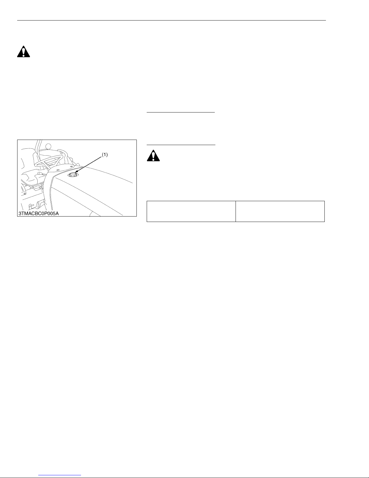
1. Turn the key switch to “ON”, check the amount of fuel by fuel
gauge.
2. Fill fuel tank when fuel gauge shows 1/4 or less fuel in tank.
Fuel tank capacity
48.0 L
12.7 U.S.gals
10.6 Imp.gals
• Do not permit dirt or trash to get into the fuel system.
• Be careful not to let the fuel tank b ecome empty, oth erwise
air will enter the fuel sy stem, necess itating ble eding befo re
next engine start.
• Be careful not to spill during refueling. If should spill, wipe
it off at once, or it may cause a fire.
• To prevent condensation (water) accumulation in the fuel
tank, fill the tank before parking overnight.
(1) Fuel Tank Cap
W10662230
G-14
Page 33
MX5100, WSM
■
IMPORTANT■
IMPORTANT■
G GENERAL
Checking Engine Oil Level
CAUTION
• Be sure to stop the engine before checking the oil level.
1. Park the machine on a flat surface.
2. Check engine oil before starting the engine or 5 minutes or more
after the engine has stopped.
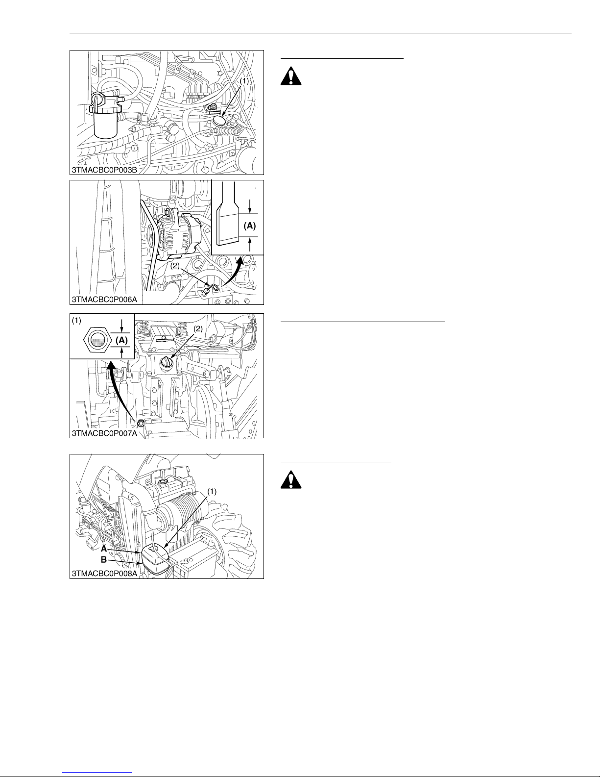
3. To check the oil level, draw out the dipstick, wipe it clean, replace
it, and draw it out again. Check to see that the oil level lies
between the two notches.
If the lev el i s to o lo w, a nd new o il to th e pre s cribe d le vel at t he oi l
inlet. (See page G-8.)
IMPORTANT
• When using an oil of different maker or viscosity from the
previous one, remove all of the old oil.
Never mix two different types of oil.
• If oil level is low, do not run the engine.
(1) Oil Inlet
(2) Dipstick
(A) Oil level is acceptable within this
range.
W10672390
Checking Transmission Fluid Level
1. Park the machine on a flat surface, lower the implement and shut
off the engine.
2. View the fluid level through the fluid level gauge.
If the lev el i s to o lo w, a dd new o il to th e pre s cribe d le vel at t he oi l
inlet. (See page G-8.)
• If oil level is low, do not run the engine.
(1) Gauge
(2) Oil Inlet
(A) Oil level is acceptable within this
range.
W10682390
Checking Coolant Level
CAUTION
• Do not remove radiator cap while coolant is hot. When cool,
slowly rotate cap to the first stop and allow sufficient time
for excess pressure to escape before removing the cap
completely.
1. Check to see that the coolant lev el is between the “FULL” and
“LOW” marks of recovery tank.
2. When the coolant level drops due to evaporation, add water only
up to the full level.
In case of lea kage, add anti -freeze and water in the specif ied
mixing ratio up to the full level.
(See “Flush Cooling System and Changi ng Cool ant” in “CHE CK
POINTS OF EVERY 2 YEARS”.)
• If the radiator cap has to be removed, follow the caution
above and securely retighten the cap.
• Use clean, fresh water and anti-freeze to fill the recovery
tank.
• If water should leak, stop the water leaking.
(1) Recovery Tank A : FULL
B : LOW
W10690120
G-15
Page 34
MX5100, WSM
■
G GENERAL
Cleaning Front Grille and Radiator Screen
CAUTION
• Be sure to stop the engine before removing the screen.
1. Fully turn the steering handle clockwise.
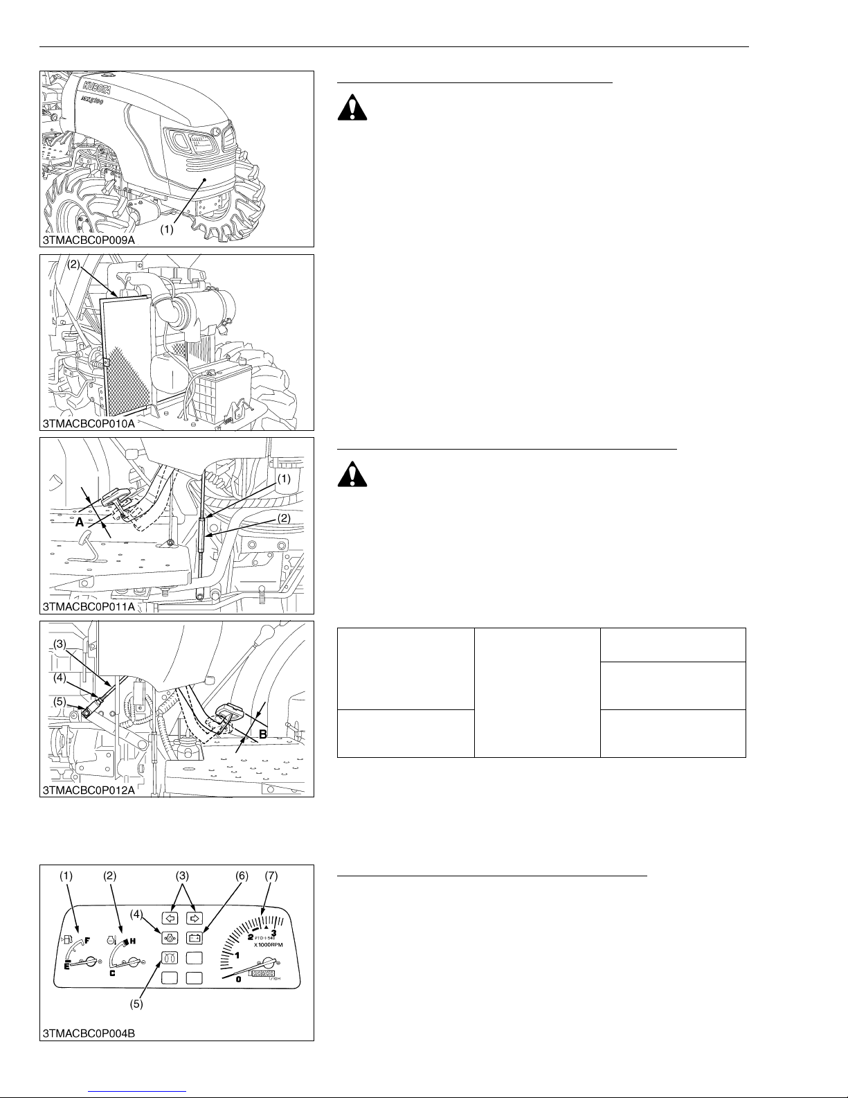
2. Check front grille to be sure it is clean from debris.
3. Open the bonnet.
4. Detach the screen and remove all the foreign material.
IMPORTANT
• Grille and screen must be clean from debris to prevent
engine from overheating and to allow good air inta ke for the
air clean er.
(1) Front Grille (2) Radiator Screen
W10698580
Checking Brake Pedals and CLutch Pedal Free Play
WARNING
• Be sure brake pedals have equal adjustment when using
locked together. Incorrect or unequal brake pedal
adjustment can cause the tractor to swerve or roll-over.
1. Inspect the br ake and clutc h pedals for fr ee travel, and smooth
operation.
2. Adjust if incorrect measurement is found:
(See “Adjusting Clutch Pedal” and “Adjusting Brake Pedal” in
“CHECK POINTS OF EVERY 100 HOURS”.)
15 to 20 mm
(5/8 to 13/16 in.)
Brake pedal free play
Clutch pedal free play
(1) Lock Nut
(2) Turnbuckle
(3) Clutch Rod
(4) Nut
(5) Cotter Pin
Factory spec.
A : Free Travel (Brake Pedal)
B : Free Travel (Clutch Pedal)
Keep the free travel in the
right and left brake pedals
equal.
20 to 30 mm
(13/16 to 1-3/16 in.) on
the pedal
W10704140
Checking Gauge, Meter and Easy Checker (TM)
1. Inspect the instr ument panel for broken ga uge(s), metal(s) and
Easy Checker(TM).
2. Replace it if it is broken.
(1) Coolant Temperature Gauge
(2) Fuel Gauge
(3) Turn Signal / Hazard Light indicator
(4) Engine Oil Pressure Lamp
(5) Glow Plug Indicator
(6) Electrical Charge Lamp
(7) Hourmeter / Tachometer
W10719690
G-16
Page 35
MX5100, WSM
G GENERAL
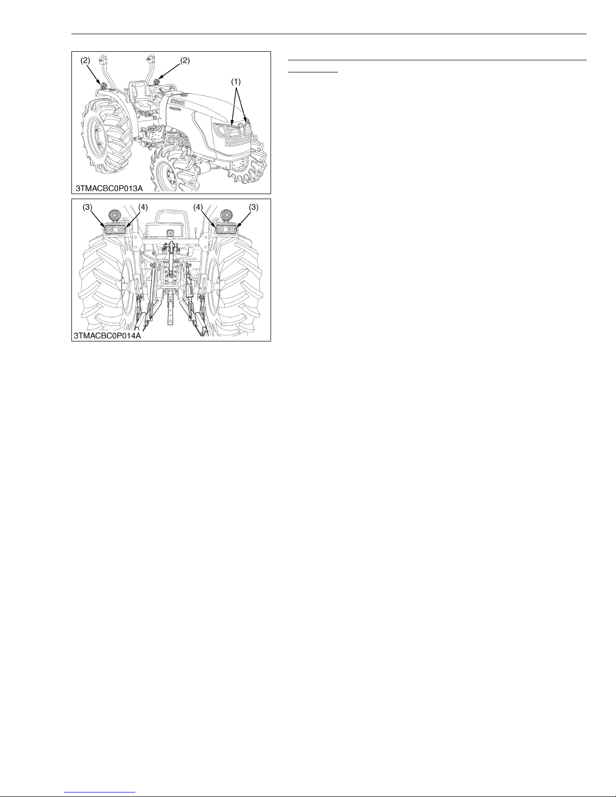
Checking Head Lights, Hazard Lights, Turn Signal Lights and
Tail Lights
1. Inspect the lights for broken bulbs and lenses of the lights.
2. Replace it if it is broken.
(1) Head Light
(2) Side Turn Signal / Hazard Light
(3) Tail Light
(4) Rear Turn Signal / Hazard Light
W10724340
G-17
Page 36
MX5100, WSM
G GENERAL
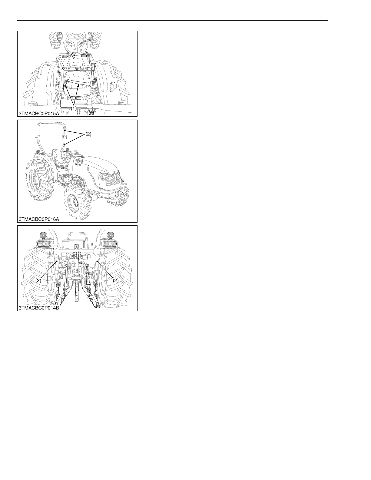
Checking Seat Belt and ROPS
1. Always check con dition of se at belt (1) and ROPS (2) attaching
hardware before operating tractor.
2. Replace it if it is damaged.
(1) Seat Belt (2) ROPS
W10729850
G-18
Page 37
MX5100, WSM
[2] CHECK POINTS OF INITIAL 50 HOURS
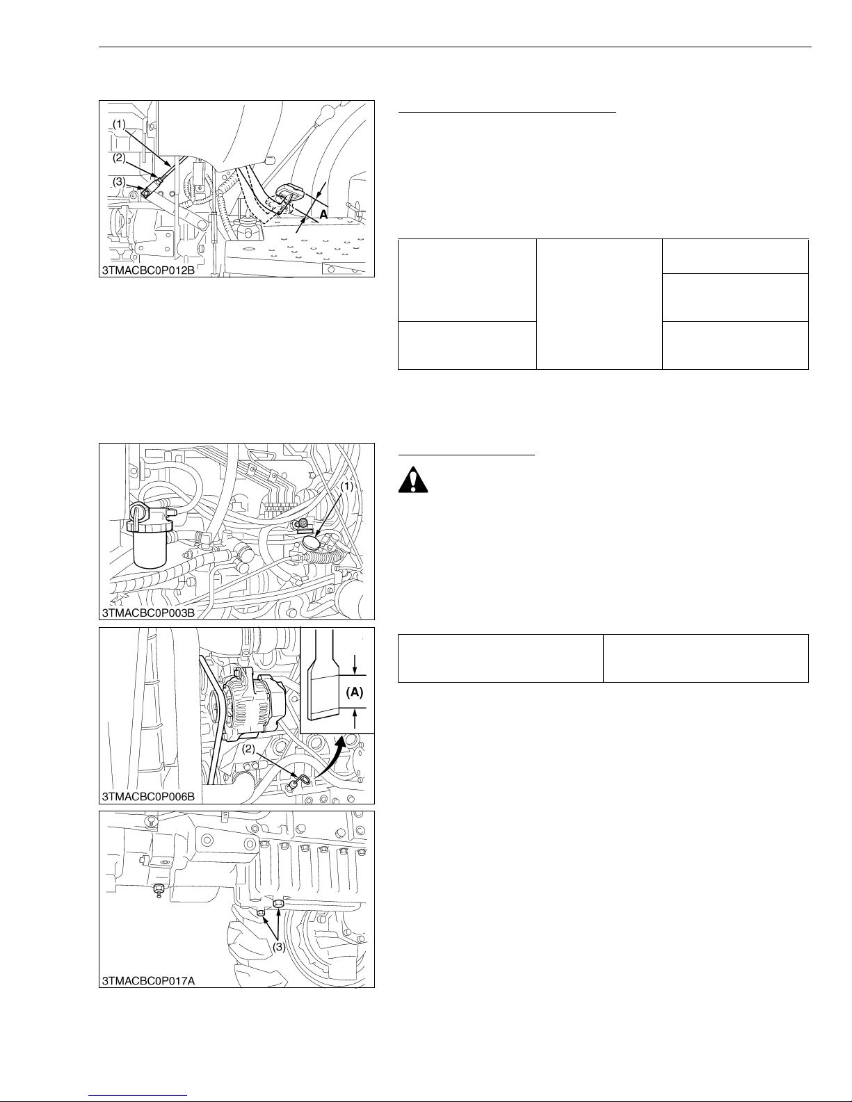
Adjusting Clutch Pedal Free Play
1. Stop the engine and remove the key.
2. Slightly depress th e clutch pedal an d measure f ree travel at top
of pedal stroke.
3. If adjustment is needed, loose n the lock nut, remove the cotter
pin and adjust the rod length within acceptable
limits.
4. Retighten the lock nut and split the cotter pin.
Brake pedal free play
Clutch pedal free play
Factory spec.
G GENERAL
15 to 20 mm
(5/8 to 13/16 in.)
Keep the free travel in the
right and left brake pedals
equal.
20 to 30 mm
(13/16 to 1-3/16 in.) on
the pedal
(1) Clutch Rod
(2) Nut
(3) Cotter Pin
A : Free Travel.
W10743050
Changing Engine Oil
CAUTION
• Be sure to stop the engine before changing the oil.
• Allow engine to cool down sufficiently, oil can be hot and
can burn.
1. To drain the used oil, remove the both drain plugs (1) at the
bottom of the engine and drain the oil completely into the oil pan.
2. After draining reinstall the drain plug.
3. Fill with the new oil up to upper notch on the dipstick (2).
(See page G-8.)
Engine oil capacity (with filter)
(1) Oil Inlet
(2) Dipstick
(3) Drain Plug
8.0 L
8.5 U.S.qts
7.0 Imp.qts
(A) Oil level is acceptable within this
range.
W10145330
G-19
Page 38
MX5100, WSM
■
■
G GENERAL
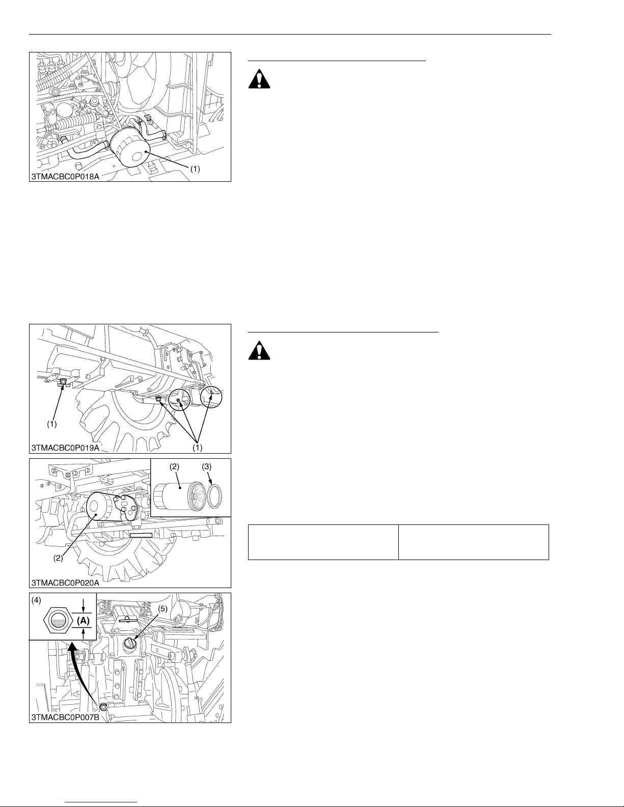
Replacing Engine Oil Filter Cartridge
CAUTION
• Be sure to stop the engine before changing the oil filter
cartridge.
• Allow engine to cool down sufficiently, oil can be hot and
can burn.
1. Remove the oil filter.
2. Place a oil pan under the engi ne oil filte r cartr idge. Pu t a film of
clean engine oil on the rubber seal of the new filter.
3. Tighten the filter quickly until it contacts the mounting surface.
Tighten filter by hand a additional 1/2 turn only.
4. After the new fil ter has been replaced, the engin e oil normally
decreases a little. Make sure that th e engine oil does not leak
through the seal and be sure to check the oil level on the dipstick.
Then, replenish the engine oil up to the prescr ib ed lev el .
IMPORTANT
• To prevent serious damage to the engine, use only a
KUBOTA genuine filter.
(1) Engine Oil Filter Cartridge
W10148920
Replacing Hydraulic Oil Filter Cartridge
CAUTION
• Be sure to stop the engine before changing the oil filter
cartridge.
• Allow engine to cool down sufficiently, oil can be hot and
can burn.
1. Remove the dr ain plugs at the bott om of the transmi ssion case
and drain the oil completely into the oil pan.
2. After draining reinstall the drain plugs.
3. Remove the oil filter.
4. Wipe off metal fillings from the magnetic filter with a clean rag.
5. Quickly tigh ten the filter until it contacts the mounting sur face,
then tighten it by hand an additional 1/2 turn only.
6. After the new filter has been replaced, fill with oil up to the upper
line of the gauge.
44.0 L
Oil capacity
11.6 U.S.gals
9.7 Imp.gals
7. After running the engine for a few minutes, stop the engine a nd
check the oil level again, add oil to the prescribed level.
8. Make sure that the transmission fluid does not leak past the seal
on the filter.
IMPORTANT
• To prevent serious damage to the hydraulic system. Use
only a KUBOTA genuine filter.
• Do not operate th e tractor immediately after changing the
transmission fluid.
Run the engine at medium speed for a few minutes to
prevent damage to the transmission.
(1) Drain Plugs
(2) Hydraulic Oil Filter
(3) Magnetic Filter (Wipe off Metal
Fillings)
(4) Gauge
(5) Oil Inlet
(A) Oil level is acceptable within this
range.
W10155860
G-20
Page 39
MX5100, WSM
NOTE■
[3] CHECK POINTS OF EVERY 50 HOURS
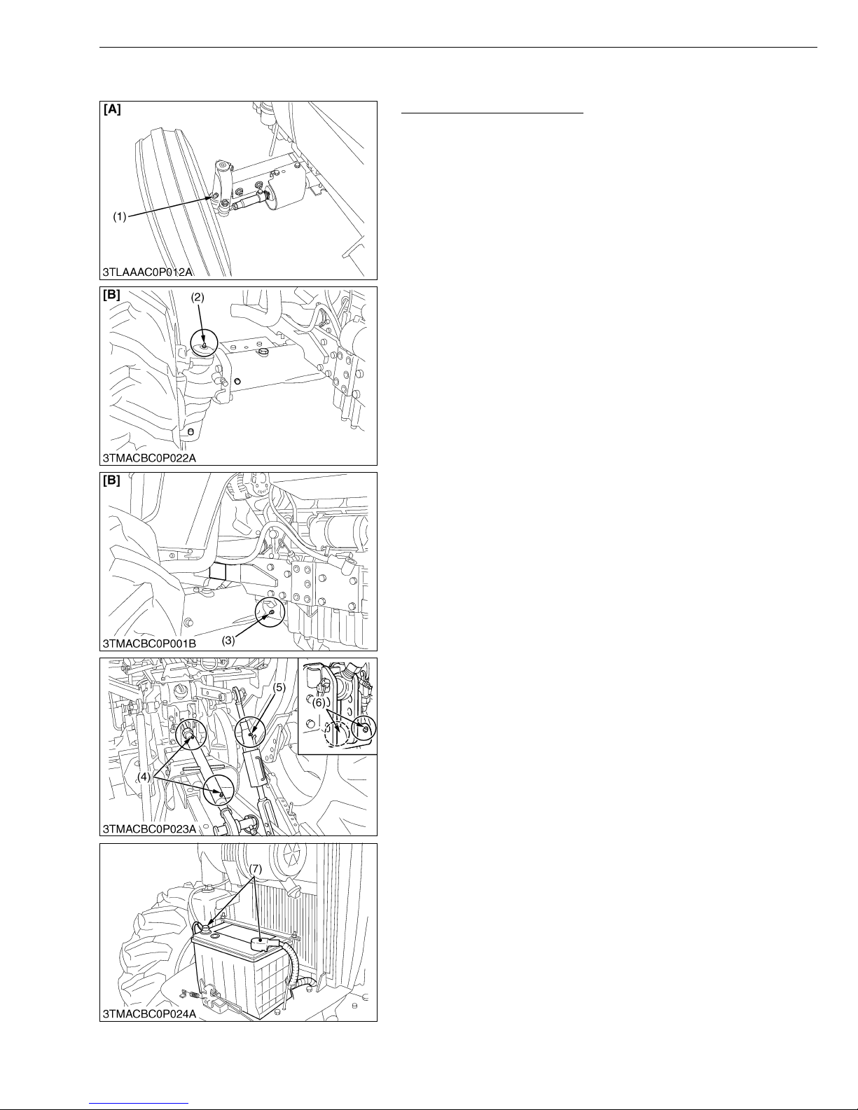
Lubricating Grease Fittings
1. Apply a small amou nt of multi-purpose grease to the following
positions shown in the figures.
• Apply a small amount of multipurpose grease to the
following points every 50 hours.
If the machine is operated in extremely wet and muddy
conditions, lubricating grease fittings more often.
• When apply a grease to the front axle support, remove the
breather plug and apply a grease until grease overflows
from breather plug. After greasing reinstall the plug.
(1) Grease Fitting (Knuckle Shaft RH,
LH)
(2) Grease Fitting (Front Wheel Case
Support RH, LH)
(3) Grease Fitting (Front Axle Support)
(4) Grease Fitting (Top Link)
(5) Grease Fitting (Lifting Rod RH)
(6) Grease Fitting (Top link bracket, if
equipped with draft control)
(7) Battery Terminal
G GENERAL
[A] 2WD Type
[B] 4WD Type
W10308650
G-21
Page 40
MX5100, WSM
G GENERAL
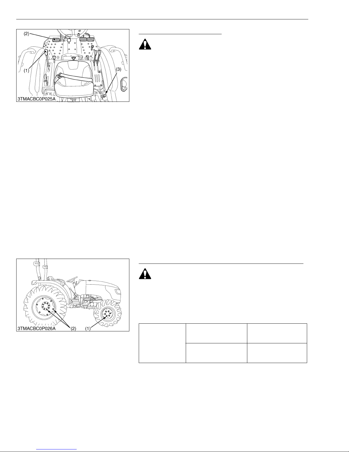
Checking Engine Start System
CAUTION
• Do not allow anyone near the tractor while testin g.
• If the tractor does not pass the test, do not operate the
tractor.
■ Preparation before testing.
1. Place all control levers in the “NEUTRAL” position.
2. Set the parking brake and stop the engine.
■ Test 1 : Switch for the shuttle shift lever.
1. Sit on operator’s seat.
2. Shift the shuttle shift lever to the forward or reverse position.
3. Depress the clutch pedal fully.
4. Disengage the PTO clutch control lever.
5. Turn the key to “START” position.
6. The engine must not crank.
■ Test 2 : Switch for the PTO clutch control lever.
1. Sit on operator’s seat.
2. Engage the PTO clutch control lever.
3. Depress the clutch pedal fully.
4. Shift the shuttle shift lever to the neutral position.
5. Turn the key to “START” position.
6. The engine must not crank.
■ Test 3 : Switch for the operator’s seat.
1. Sit on operator’s seat.
2. Depress the clutch pedal fully.
3. Start the engine.
4. Engage the PTO gear shift lever.
5. Stand up. (Do not get off the machine.)
6. The engine must shut off after approximately 1 second.
(1) Shuttle Shift Lever
(2) Clutch Pedal
(3) PTO Clutch Control Lever
W10312010
Checking Wheel Mounting Bolts and Nuts Tightening Torque
CAUTION
• Never operate tractor with a loose rim, wheel, or axle.
• Any time bolts and nuts are loosened, retighten to specified
torque.
• Check all bolts and nuts frequently and keep them tight.
1. Check wheel bol ts and nuts regularly especially when new. If
they are loose, tighten them as follows.
124.0 to 147.0 N·m
Front wheel mounting nuts
Tightening torque
Rear wheel mounting bolts
and nuts
(1) Front Wheel Mounting Nuts (2) Rear Wheel Mounting Bolts and Nuts
12.6 to 15.0 kgf·m
91.5 to 108.4 lbf·ft
196.0 to 225.0 N·m
20.0 to 23.0 kgf·m
144.6 to 166.0 lbf·ft
W10309990
G-22
Page 41
MX5100, WSM
[4] CHECK POINTS OF EVERY 100 HOURS
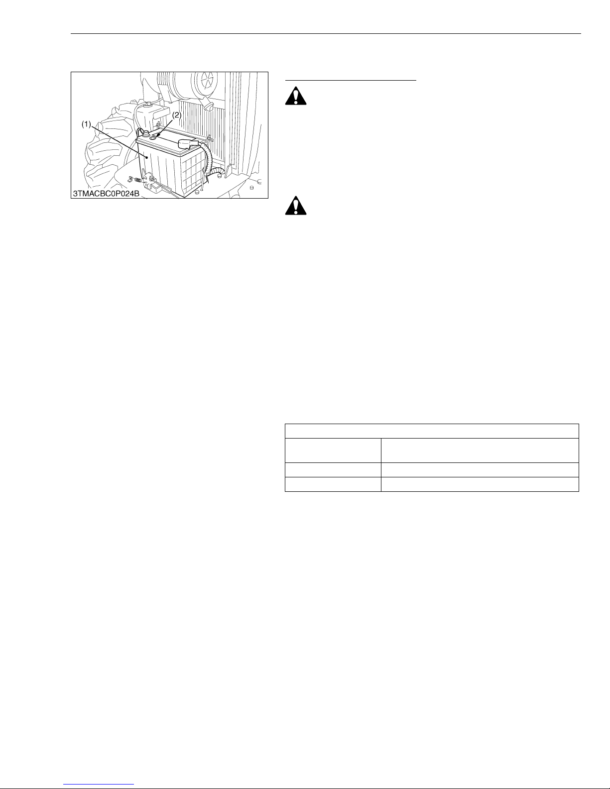
Checking Battery Condition
DANGER
• Do not use or charge the refillable type battery if the fluid
level is below the LOWER (lower limit level) mark.
Otherwise, the battery component parts may prematurely
deteriorate, which ma y shorten the batte ry’s service life or
cause an explosion. Check the fluid level regularly and add
distilled water as required so that the fluid level is between
the UPPER and LOWER levels.
CAUTION
• Never remove the vent caps while the engine is running.
• Keep electrolyte away from ey es, h and s and clo the s. If you
are spattered with it, wash it away completely with water
immediately and get medical attention.
• Wear eye protection and rubber gloves when working
around the battery.
The factory-installed battery is of non-refillable type. If the
indicator turns white, do not change the battery but r eplace it with
new one.
1. Mishandling the battery shortens the service life and adds to
maintenance costs.
2. The original battery is maintenance free, but need some
servicing.
If the battery is weak, the engine will be difficult to st art and the
lights will be dim. It is important check the battery periodically.
■ How to read the indicator
Check the battery condition by reading the indicator.
Green
Black Needs charging battery
White Needs replacing battery
G GENERAL
State of indicator display
Specific gravity of electrolyte and quality of
electrolyte are both in good condition.
(1) Battery (2) Indicator
W10790200
G-23
Page 42
MX5100, WSM
G GENERAL
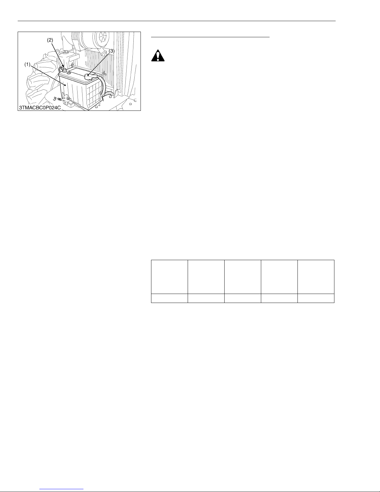
Checking Battery Condition (Continued)
■ Battery Charging
CAUTION
• When the battery is being activated, hydrogen and oxygen
gases in the battery are extremely explosive. Keep open
sparks and flames away from the battery at all times,
especially when charging the battery.
• When charging the battery, ensure the vent caps are
securely in place. (If equipped.)
• When disconnecting the cable from the battery, start with
the negative terminal first.
When connecting the cable to the battery, start with the
positive terminal first.
• Never check battery charge by placing a metal object across
the posts.
Use a voltmeter or hydrometer.
1. To slow charge the battery, connect the battery positive terminal
to the charger positive terminal and the negative to the negative,
then recharge in the standard fashion.
2. A boost charge is only for emergencies. It will partially charge the
battery at a high rate and in a short time.
When using a boost-charged battery, it is necessary to recharge
the battery as early as possible.
Failure to do this will shorten the battery's service life.
3. The battery is charge d if the indicator display turns green fr om
black.
4. When exchangin g an old battery for a new one, us e battery of
equal specification shown in TABLE 1.
Table 1
Battery type Volts (V)
80D26R 12 133 582 6.5
Reserve
capacity
(min)
Cold
cranking
ampere
(SAE)
(A)
Normal
charging rate
(A)
■ Direction for Storage
1. When storing the tractor for a long perio d, remove the battery
from tractor, adjust the electrolyte to the proper level and store in
a dry place out of direct sunlight.
2. The battery self-discharges while it is stored.
Recharge it once every three months in hot se asons and once
every six months in cold season s.
(1) Battery
(2) Negative Terminal
(3) Positive Terminal
W1019057
G-24
Page 43
MX5100, WSM
G GENERAL
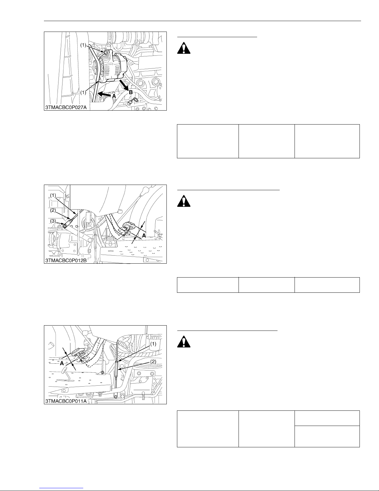
Adjusting Fan Belt Tension
CAUTION
• Be sure to stop the engine before checking and adjusting
the belt tension.
1. Stop the engine and remove the key.
2. Apply moderate thumb pressure to belt between pulleys.
3. If tension is incorrec t, loosen the alternator mo unting bolts and
using a lever placed between the alternator and the engine block,
pull the alternator out until the deflection of the belt falls within the
factory specifications.
4. Replace fan belt if it is damaged.
A deflection is 12 mm
(0.48 in.) when the belt is
Fan belt tension Factory spec.
(1) Alternator Mounting Bolt A : Check the belt tension
B : To Tighten
pressed (68.6 N (7 kgf,
15.4 lbf)) in the middle of
the span.
W10326270
Adjusting Clutch Pedal Free Travel
CAUTION
• When checking and adjusting the clutch pedal free travel,
park the tractor on a flat ground, apply the parking brake,
stop the engine and remove the key,
1. Stop the engine and remove the key.
2. Slightly depress th e clutch pedal an d measure free tra vel (A) at
top of pedal stroke.
3. If adjustment is needed, loosen the lock nut (2), remove the cotter
pin (3) and adjust the rod length within acceptable limits.
4. Retighten the lock nut (2) and split the cotter pin.
Clutch pedal free travel Factory spec.
(1) Clutch Rod
(2) Lock Nut
(3) Cotter Pin
A : Free Travel
20 to 30 mm (13/16 to 13/16 in.) on the pedal
W10329220
Adjusting Brake Pedal Free Travel
CAUTION
• Stop the engine and chock the wheels before checking
brake pedal.
1. Release the parking brake.
2. Slightly depress the brake pedals and measure free travel (A) at
top of pedal stroke.
3. If adjustment is needed, loosen the lock nut (1) and turn the
turnbuckle (2) to adjust the rod length within acceptable limits
4. Retighten the lock nut (1).
15 to 20 mm (5/8 to 13/16
in.) on the pedal
Brake pedal free travel Factory spec.
Keep the free travel in the
right and left brake pedals
equal
(1) Lock Nut
(2) Turnbuckle
G-25
A : Free Travel
W10331810
Page 44
MX5100, WSM
IMPORTANT■
NOTE■
IMPORTANT■
G GENERAL
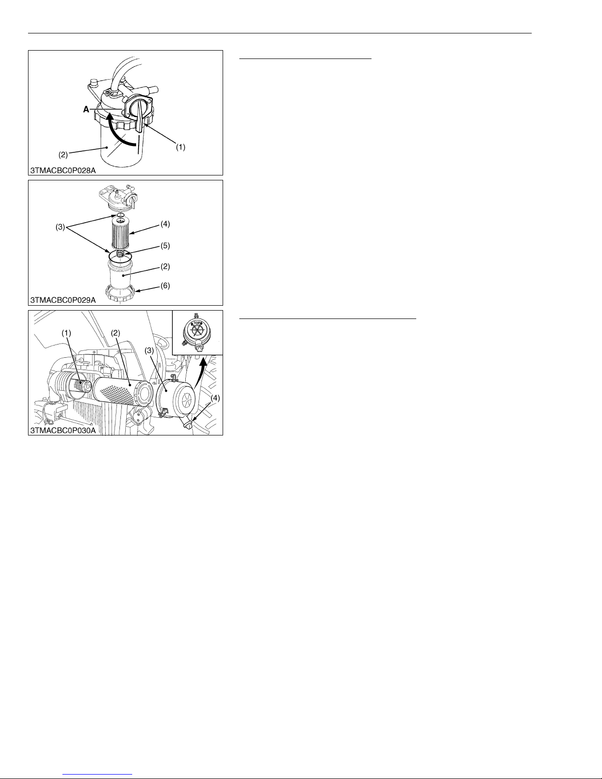
Cleaning Fuel Filter Element
This job should not be done in the field, but in a clean place.
1. Close the fuel filter cock (1).
2. Unscrew the screw ring (6) and remove the filter bowl (2), and
rinse the inside with kerosene.
3. Take out the element (4) and dip it in the kerosene to rinse.
4. After cleaning, reassemble the fuel filter, keeping out dust and
dirt.
5. Bleed the fuel system. (See page G-41.)
• If dust and dirt enter the fuel system, the fuel pump and the
injection nozzles are subject to premature wear.
To prevent this, be sure to clean the fuel filter bowl and
element periodically.
(1) Fuel Filter Cock
(2) Fuel Filter Bowl
(3) O-ring
(4) Filter Element
(5) Spring
(6) Screw Ring
A : Close
W10174670
Cleaning Air Cleaner Primary Element
1. Remove the air cleaner cover (3) and primary element (2).
2. Clean the primary element :
- When dry dus t adheres to the element, blow compressed ai r
from the inside, turning the eleme nt. Pressure of co mpress ed
air must be under 205 kPa (2.1 kgf/cm
2
, 30 psi).
- When car bon or o il adhere s to the element, soak the element
in detergent for 15 minutes then wash it several times in water,
rinse with clean water and dry it naturally. After element is fully
dried, inspect inside of the element with a light and check if it is
damaged or not.
3. Replace the air cleaner primary element :
Once yearly or after every sixth cleaning, whichever comes first.
• Check to see if the evacuator valve is blocked with dust.
• The air cleaner uses a dry element, never apply oil.
• Do not run the engine with filter element removed.
• Be sure to refit the cover the arrow ↑ (on the rear of cover)
upright. If the cover is improperly fitted, evacuator valve will
not function and dust will adhere to the element.
• Do not touch the secondary element except in cases where
replacing is required.
(See “Replacing Air Cleaner Secondary Element” in “Every
1 year” in Maintenance.)
■ Evacuator Valve
Open the evacuator valve once a week under ordinary conditions
or daily when used in a dusty place to get rid of large particles of dust
and dirt.
(1) Secondary Element
(2) Primary Element
(3) Cover
(4) Evacuator Valve
W10322160
G-26
Page 45
MX5100, WSM
■
IMPORTANT■
G GENERAL
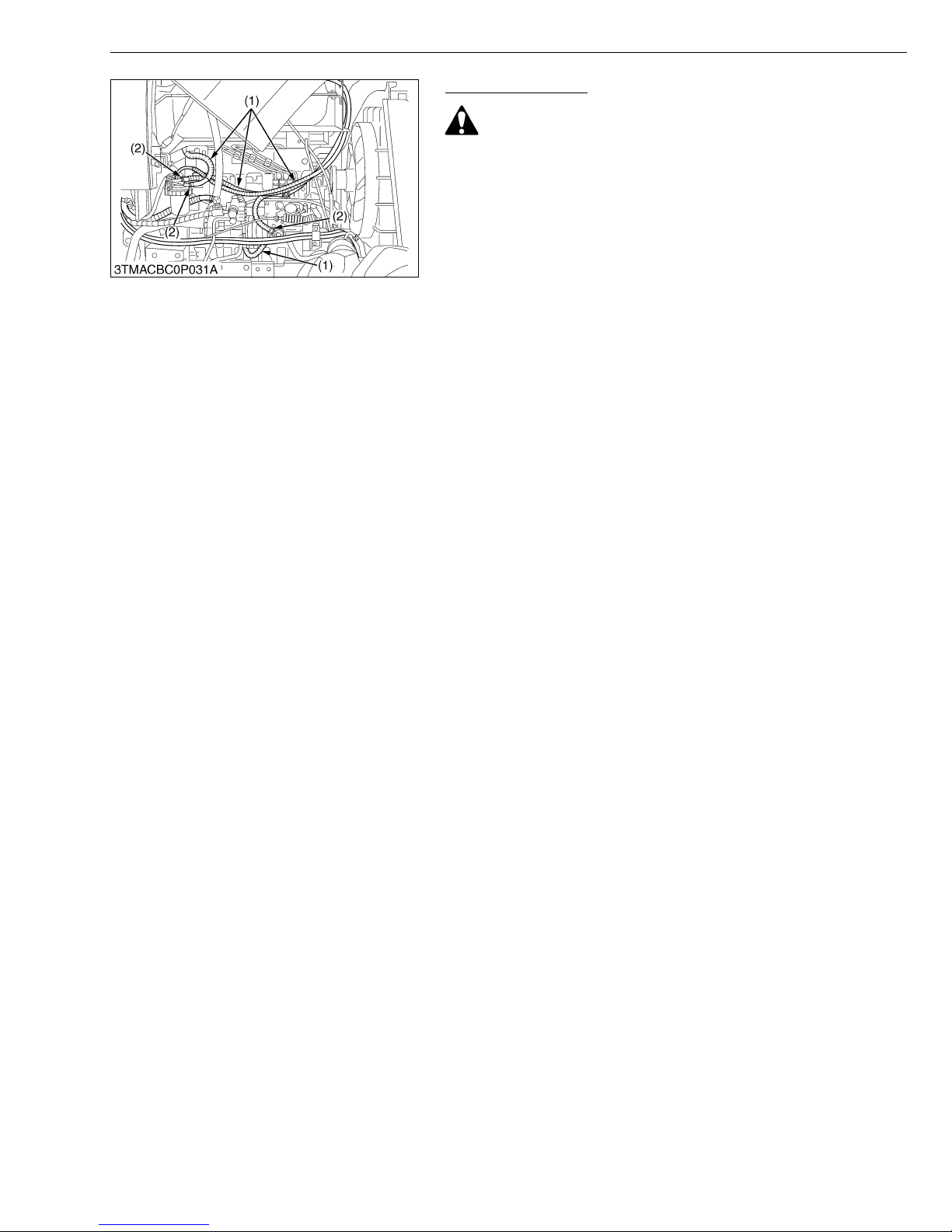
Checking Fuel Line
CAUTION
• Stop the engine when attempting the check and change
prescribed below.
• Remember to check the fuel line p eriodically. The fuel line
is subject to wear and aging, fuel may leak out onto the
running engine, causing a fire.
1. Check to see that all line and hose clamp are tight and not
damaged.
2. If hoses and clamps are found worn or damaged, replace or
repair them at once.
NOTE
• If the fuel line is removed, be sure to properly bleed the fuel
system.
(See page G-41.)
• When the fuel line is disconnected for change, close both
ends of the fuel line with a piece of clean cloth or paper to
prevent dust and dirt from entering. Entrance of dust and
dirt causes malfunction of the fuel injection pump. In
addition, particular care must be taken not to admit dust and
dirt into the fuel pump.
(1) Fuel Hose (2) Clamp Band
W10342570
G-27
Page 46
MX5100, WSM
IMPORTANT■
[5] CHECK POINTS OF EVERY 200 HOURS
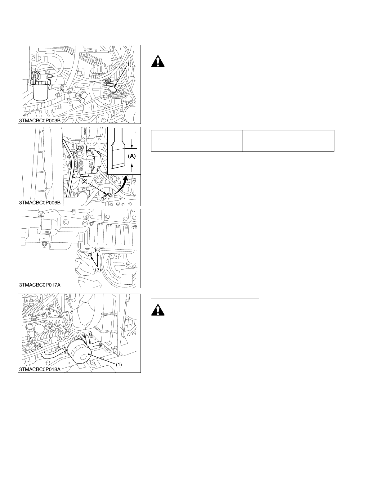
Changing Engine Oil
CAUTION
• Be sure to stop the engine before changing the oil.
• Allow engine to cool down sufficiently, oil can be hot and
can burn.
1. To drain the used oil, remove the both drain plugs (1) at the
bottom of the engine and drain the oil completely into the oil pan.
2. After draining reinstall the drain plug.
3. Fill with the new oil up to upper notch on the dipstick (2).
(See page G-8.)
Engine oil capacity (with filter)
G GENERAL
8.0 L
8.5 U.S.qts
7.0 Imp.qts
(1) Oil Inlet
(2) Dipstick
(3) Drain Plug
(A) Oil level is acceptable within this
range.
W10840000
Replacing Engine Oil Filter Cartridge
CAUTION
• Be sure to stop the engine before changing the oil filter
cartridge.
• Allow engine to cool down sufficiently, oil can be hot and
can burn.
1. Remove the oil filter.
2. Place a oil pan under the engi ne oil filte r cartr idge. Pu t a film of
clean engine oil on the rubber seal of the new filter.
3. Tighten the filter quickly until it contacts the mounting surface.
Tighten filter by hand a additional 1/2 turn only.
4. After the new fil ter has been replaced, the engin e oil normally
decreases a little. Make sure that th e engine oil does not leak
through the seal and be sure to check the oil level on the dipstick.
Then, replenish the engine oil up to the prescr ib ed lev el .
• To prevent serious damage to the engine, use only a
KUBOTA genuine filter.
(1) Engine Oil Filter Cartridge
W10844850
G-28
Page 47
MX5100, WSM
IMPORTANT■
G GENERAL
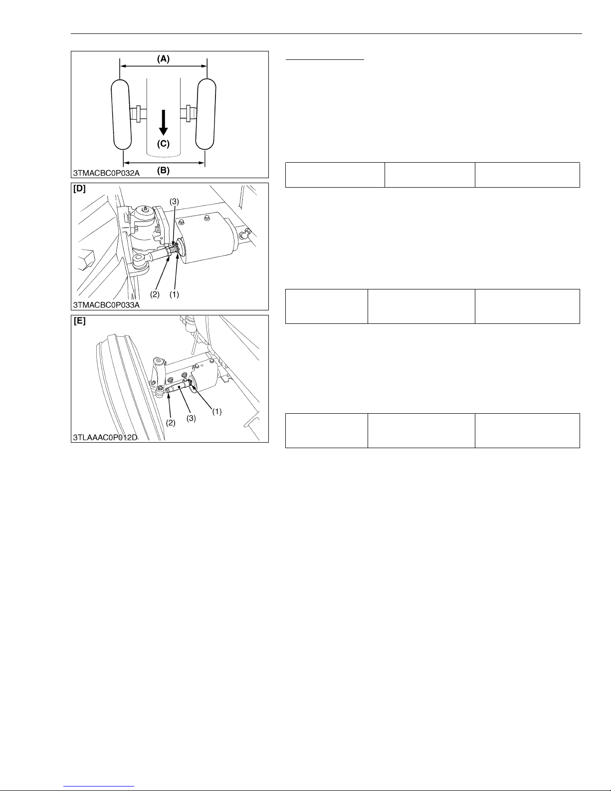
Adjusting Toe-in
1. Park the tractor on a flat place.
2. Turn steering wheel so front wheels are in the straight ahead
position.
3. Lower the implement, lock the park brake and stop the engine.
4. Measure distance between tire beads at front of tire, hub height.
5. Measure distance between tire beads at rear of tire, hub height.
6. Front distance should be 2 to 8 mm (0.079 to 0.315 in.) less than
rear distance.
Toe-in ((B) - (A)) Factory spec.
2 to 8 mm
0.079 to 0.315 in.
■ Adjusting
[4WD]
1. Detach the snap ring (1).
2. Loosen the tie-rod nut (2).
3. Turn the tie-rod joint to adjust the rod length until the proper toein measur ement is obtained.
4. Retighten the tie-rod nut (2).
5. Attach the snap ring of the tie-rod joint (3).
167 to 196 N·m
Tightening torque Tie-rod nut (4WD)
17 to 20 kgf·m
123.2 to 144.6 lbf·ft
[2WD]
1. Detach the snap ring (1).
2. Loosen the tie-rod nut (2).
3. Turn the tie-rod joint to adjust the rod length until the proper toein measur ement is obtained.
4. Retighten the tie-rod nut (2) and rod mounting screw.
5. Attach the snap ring of the tie-rod joint (3).
Tightening torque Tie-rod nut (2WD)
196 to 226 N·m
20 to 23 kgf·m
144.6 to 166.4 lbf·ft
• A right and left tie-rod joint is adjusted to the same length.
(1) Snap Ring
(2) Tie-rod Nut
(3) Tie-rod Joint
(A) Wheel to Wheel Distance at front
(B) Wheel to Wheel Distance at rear
(C) Front
[D] 4WD
[E] 2WD
W10846230
G-29
Page 48
MX5100, WSM
G GENERAL
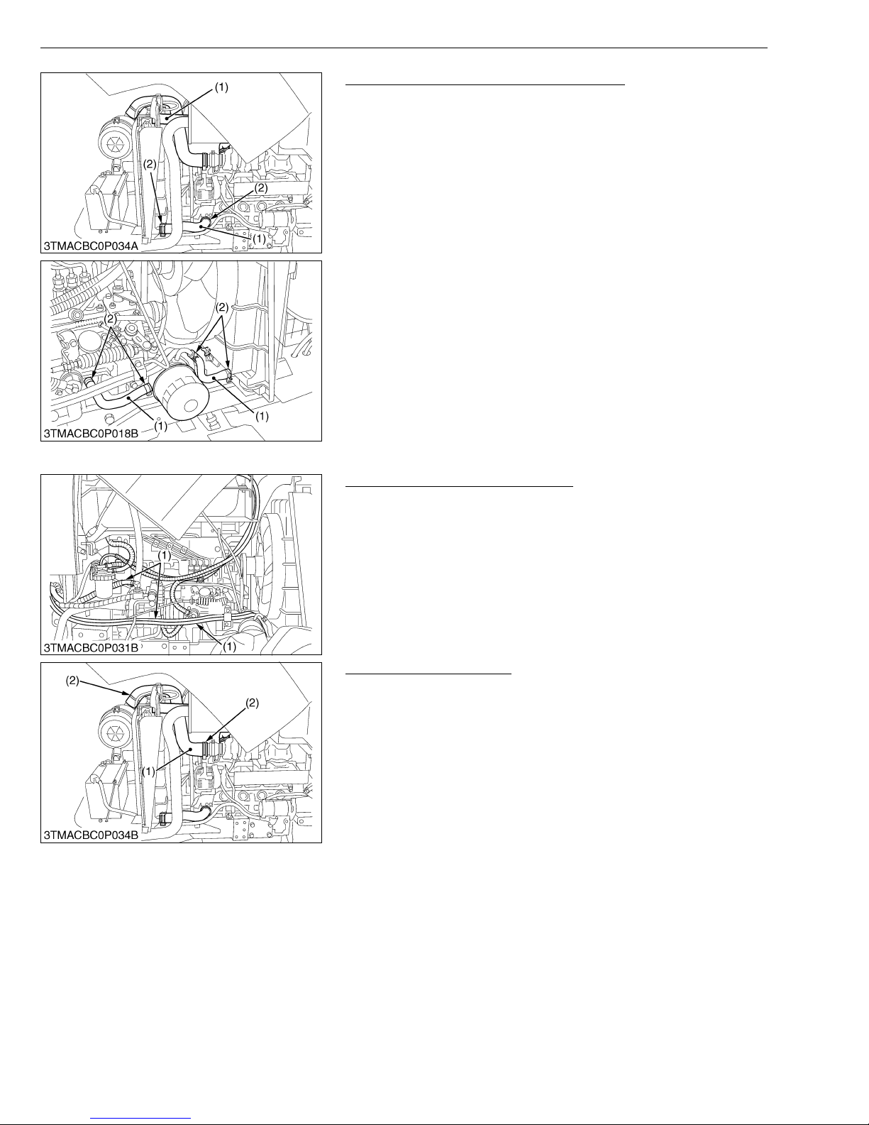
Checking Radiator Hose and Hose Clamp
Check to see if radiator hoses are properly fixed every 200 hours
of operation or six months, whichever comes first.
1. If hose clamps are loose or water leaks, tighten bands securely.
2. Replace hoses and tighten hose clamps securely, if radiator
hoses are swollen, hardened or cracked.
Replace hoses and hose clamps every 2 years or earlier if
checked and found that hoses are swollen, hardened or cracked.
■ Precaution at Overheating
Take the following actions in the event the coola nt temperature
be nearly or more than the boiling point, what is called
“Overheating”.
1. Park the tractor in a safe place and keep the eng ine unloaded
idling.
2. Do not stop the engine suddenly, but stop it after about 5 minutes
of unloaded idling.
3. Keep yours el f w e ll aw ay f ro m t he ma ch in e f or f ur t he r 10 mi n ut es
or while the steam blows out.
4. Check that there are no dangers such as burns, get rid of the
causes of overheating according to the manual, see
“Troubleshooting” section, and then, start again the engine.
(1) Radiator Hose (2) Clamp
W10347370
Checking Power Steering Oil Line
1. Check to see that all lines and hose clamps are tight and not
damage.
2. If hoses and clamps are found worn or damaged, replace or
repair them at once.
(1) Power Steering Pressure Hoses
W10346350
Checking Intake Air Line
1. Check to see that hoses and hose clamps are tight and not
damaged.
2. If hoses and clamps are found worn or damaged, replace or
repair them at once.
(1) Hose (2) Hose Clamp
W10345660
G-30
Page 49
MX5100, WSM
■
[6] CHECK POINTS OF EVERY 400 HOURS
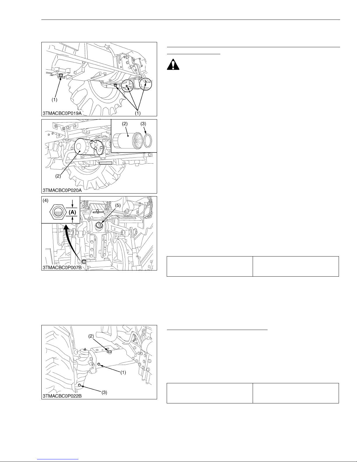
Replacing Hydraulic Oil Filter Cartridge and Changing
Transmission Fluid
CAUTION
• Be sure to stop the engine before replacing the oil filter
cartridge.
• Allow engine to cool down sufficiently, oil can be hot and
can burn.
1. Remove the drain plug s at the bottom of the transmiss ion case
and drain the oil completely into the oil pan.
2. After draining reinstall the drain plugs.
3. Remove the oil filter cartridge.
4. Wipe off metal fillings from the magnetic filter with a clean rag.
5. Put a film of clean transmission oil on the rubber seal of the new
filter cartridge.
6. Quickly tighten the filter until it contacts the mounting surface,
then tighten it by hand an additional 1/2 turn only.
7. After the new filter has been replaced, fill with oil up to the upper
line of the gauge.
8. After running the e ngine for a few minu tes, stop the engine and
check the oil level again, add oil to the prescribed level
9. Make sure that the transmission fluid does not leak past the seal
on the filter
IMPORTANT
• To prevent serious damage to the hydraulic system. Use
only a KUBOTA genuine filter.
• Do not operate the tr actor immediately after changing the
transmission fluid.
Run the engine at medium speed for a few minutes to
prevent damage to the transmission.
Oil capacity
G GENERAL
44.0 L
11.6 U.S.gals
9.7 Imp.gals
(1) Drain Plugs
(2) Hydraulic Oil Filter
(3) Magnetic Filter (Wipe off Metal
Fillings)
(4) Gauge
(5) Oil Inlet
(A) Oil level is acceptable within this
range.
W10870020
Changing Front Axle Case Oil [4WD]
1. To drain the used oil, rem ove the right and left drain pl ugs and
filling plug at the front axle case and drain the oil completely into
the oil pan.
2. After draining reinstall the drain plugs.
3. Remove the oil level check plug.
4. Fill with the new oil up to the check plug port.
5. After filling reinstall the filling plug and check plug.
Front axle oil capacity (4WD)
(1) Check Plug
(2) Filling Plug
9.0 L
9.5 U.S.qts
7.5 Imp.qts
(3) Drain Plug
W10366680
G-31
Page 50
MX5100, WSM
IMPORTANT■
NOTE■
G GENERAL
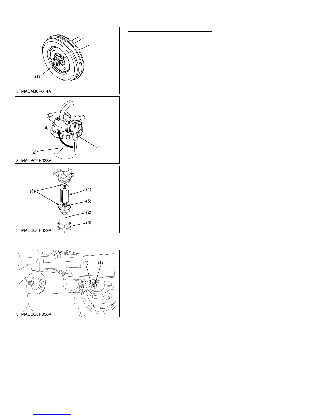
Greasing Front Wheel Hub (2WD)
1. Detach the cover, and apply bearing grease.
(1) Front Wheel Hub Cover (2WD)
W10358080
Replacing Fuel Filter Element
1. See “Cleaning Fuel Filter Element” in “CHECK POINTS OF
EVERY 100 HOURS”.
2. Replace the fuel filter element (4).
• If dust and dirt enter the fuel system, the fuel pump and the
injection nozzles are subject to premature wear.
(1) Fuel Filter Cock
(2) Fuel Filter Bowl
(3) O-ring
(4) Filter Element
(5) Spring
(6) Screw Ring
A : Close
W11084790
[7] CHECK POINT OF EVERY 600 HOURS
Adjusting Front Axle Pivot
1. Loosen the lo ck nut (2), tighten the adjusting screw (1) all the
way, and then tighten the adjusting screw (1) by 1/6 turn.
2. Retighten the lock nut (2).
3. Refer to “6. FRONT AXLE”.
• If the front axle pivot pin adjustment is not correct, front
wheel vibration can occur causing vibration in the steering
wheel.
(1) Adjusting Screw (2) Lock Nut
W11054130
G-32
Page 51
MX5100, WSM
■
NOTE■
[8] CHECK POINT OF EVERY 800 HOURS
Checking Valve Clearance
IMPORTANT
• Valve clearance must be checked and adjusted when engine
is cold.
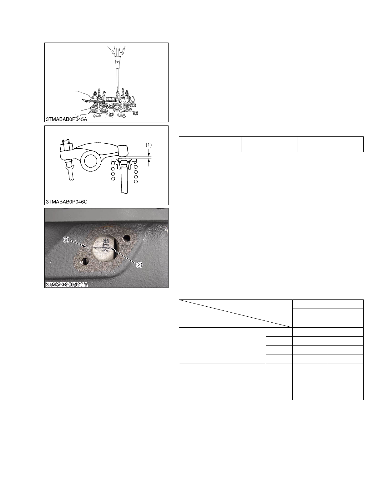
1. Remove the head cover.
2. Align the “1TC” mark line ( 3) on the flywheel and proje ction (2)
on the housing so that the No.1 piston comes to the compression
or overlap top dead center.
3. Check the following valve clearance (1) marked with “✩” using a
feeler gauge.
4. If the clearance is not within the factory specifications, adjust with
the adjusting screw.
Valve clearance Factory sp ec.
• The “1TC” mark line on the flywheel is just for No. 1 cylinder.
There is no “TC” marking for the other cylinders.
• No. 1 piston comes to the top dead center position when the
“TC” marking is aligned with the projection (2) in the window
on flywheel-housing. Turn the flywheel 0.26 rad (15 °)
clockwise and counterclockwise to see if the piston is at th e
compression top dead center or the overlap position. Now
referring to the table below, readjust the valve clearance (1).
(The piston is at the top dead center when both the IN. and
EX. valves do not move; it is at the overlap position when
both the valves move.)
• Finally turn the flywheel 6.28 rad (360 °) and align the “1TC”
mark line and the projection (2) perfectly. Adjust all the
other valve clearance as required.
• After turning the flywheel counterclockwise twice or three
times, recheck the valve clearance (1).
• After adjusting the valve clearance (1), firmly tighten the lock
nut of the adjusting screw.
Valve arrangement
G GENERAL
0.18 to 0.22 mm
0.0071 to 0.0086 in.
4 Cylinder
Adjustable cylinder
location of piston
When No. 1 piston is at
compression top dead center
When No. 1 piston is at overlap
position
(1) Valve Clearance
(2) Proje ctio n
G-33
IN. EX.
No. 1 ✩✩
No. 2 ✩
No. 3 ✩
No. 4
No. 1
No. 2 ✩
No. 3 ✩
No. 4 ✩✩
(3) 1TC Mark Line
W11135030
Page 52
MX5100, WSM
[9] CHECK POINT OF EVERY 1500 HOURS
Checking Fuel Injection Nozzle Injection Pressure
CAUTION
• Check the nozzle injection pressure and condition after
confirming that there is nobody standing in the direction of
the injected fuel.
• If the injected fuel from the nozzle directly contacts the
human body, cells may be destroyed and blood poisoning
may be caused.
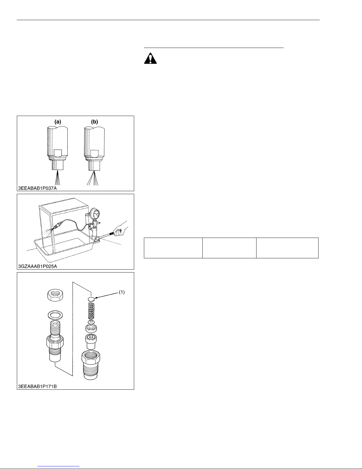
■ Nozzle Spraying Condition
1. Set the injection no zzle to a nozz le teste r, and chec k the nozz le
spraying condition.
2. If the spraying condition is defective, replace the nozzle piece.
(a) Good (b) Bad
G GENERAL
W10368740
W10181310
■ Fuel Injection Pressure
1. Set the injection nozzle to a nozzle tester.
2. Slowly move the tester handle to measure the pressure at which
fuel begins jetting out from the nozzle.
3. If the measurement is not within the factory specifications,
replace the adjusting washer (1) in the nozzle holder to adjust it.
Fuel injection pressure Factory spec.
13.73 to 14.71 MPa
140 to 150 kgf/cm
1992 to 2133 psi
2
(Reference)
• Pressure variation with 0.01 mm (0.0004 in.) difference of
adjusting washer thickness.
Approx. 235 kPa (2.4 kgf/cm
(1) Adjusting Washer
2
, 34 psi)
W10182100
G-34
Page 53
MX5100, WSM
G GENERAL
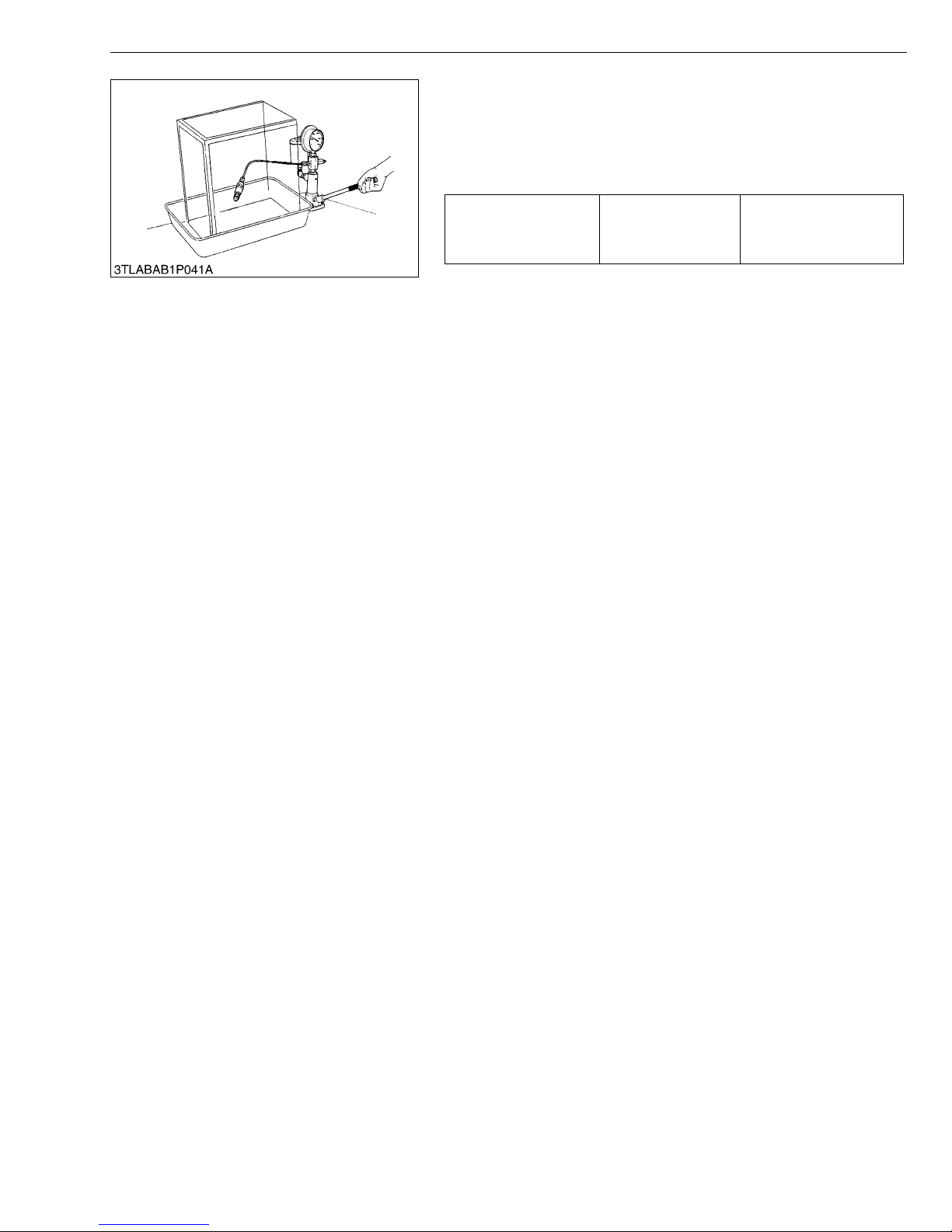
■ Valve Seat
1. Set the injection nozzle to a nozzle tester (Code No. 07909-
31361).
2. Raise the fuel pressure, and k eep at 12.75 MPa (130 kgf/cm
1849 psi) for 10 seconds.
3. If any fuel leak is found, replace the nozzle piece.
No fuel leak at
Valve seat tightness Factory spec.
12.75 MPa
130 kgf/cm
1849 psi
2
W1113031
2
,
G-35
Page 54
MX5100, WSM
NOTE■
[10] CHECK POINTS OF EVERY 3000 HOURS
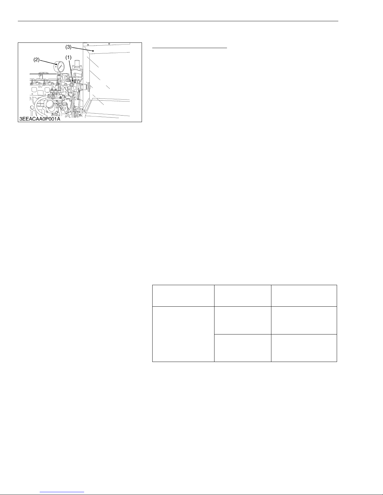
Checking Injection Pump
(Fuel Tightness of Pump Element)
1. Remove the engine stop solenoid.
2. Remove the injecti on pipe s and glo w plugs.
3. Install the injection pump pressure tester to the injection pump.
4. Install the injection nozzle (1) jetted with the proper injection
pressure to the injec tio n pum p pres s ure tes te r (2) . ( Refe r to the
figure.)
5. Set the speed control lever to the maximum speed position.
6. Run the starter to increase the pressure.
7. If the pressure can not reach the allowable limit, replace the
pump with new one or repair with a Kubota-authorized pump
service shop.
(Fuel Tightness of Delivery Valve)
1. Remove the engine stop solenoid.
2. Remove the injecti on pipe s and glo w plugs.
3. Set a pressure tester to the fuel injection pump.
4. Install the injection nozzle (1) jetted with the proper injection
pressure to the injection pump pressure tester (2).
5. Run the starter to increase the pressure.
6. Stop the starter when the fuel jets from the injection nozzle. After
that, turn the flywheel by the hand and raise the pressure to
approx. 13.73 MPa (140 kgf/cm
7. Now turn the flywheel back about half a turn (to keep the plunger
free). Maintain the flywhee l at this position and clock the time
taken for the pressure to drop from 13.73 to 12.75 MPa (from 140
to 130 kgf/cm
8. Measure the time needed to decrease the pressure from 13.73 to
12.75 MPa (from 140 to 130 kgf/cm
9. If the measurement is less than allowable limit, replace the pump
with new one or repair with a K ubota-authorized pump service
shop.
Fuel tightness of pump
element
Fuel tightness of
delivery valve
2
, from 1991 to 1849 psi).
Allowable limit
Factory spec.
Allowable limit
2
, 1991 psi).
2
, from 1991 to 1849 psi).
13.73 MPa
140 kgf/cm
1991 psi
10 seconds
13.73 → 12.75 MPa
140 → 130 kgf/cm
1991 → 1849 psi
5 seconds
13.73 → 12.75 MPa
140 → 130 kgf/cm
1991 → 1849 psi
G GENERAL
2
2
2
• Never try to disassemble the in jec tion p ump assem bl y. For
repairs, you are strongly requested to contact a Kubotaauthorized pump service shop.
(1) Injection Nozzle
(2) Injection Pump Pressure T ester
(3) Protection Cover for Jetted Fuel
W1022357
G-36
Page 55
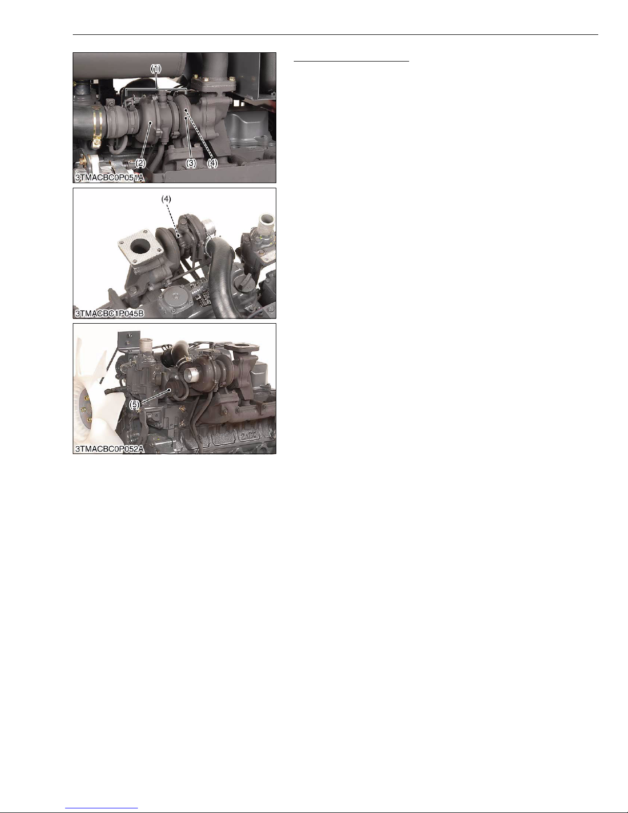
MX5100, WSM
NOTE■
G GENERAL
Checking Turbocharger
• The turbocharger component parts are not adapted. When
the part is defective, replace the turbocharger as an
assembly.
• Exhaust gas leak, carbon or engine oil leak are found,
replace the turbocharger with a new one.
[Turbine Side]
1. Check the turbine housing, exhaust gas or engine oil leak from
the turbine shaft seal ring are found, replace the turbocharger as
an assembly.
2. If any exhaust gas leak is found, retighten the bolts.
[Compressor Side]
1. Check the inlet hose to see if there is no air leak.
2. Check fo r l o os en c onn ec t ions o r cracks in the suct io n si de o f th e
inlet hose.
3. If any air leak is fou nd, tig hten or ch ange th e c la mp / o r the in le t
hose.
[Compressor Impeller]
1. Push and pull the turbi ne end nut and check radia tor clearance
the thrust clearance.
2. If the clearance is found, change the turbocharger.
[Waste Gate Valve]
1. Check the movement of the waste gate valve rod.
2. If the movement of the rod is tight, change the turbocharger.
(1) Turbocharge Assembly
(2) Turbine Side
(3) Compressor Side
(4) Compres sor Impeller
(5) Waste Gate Va lve
W10903600
G-37
Page 56
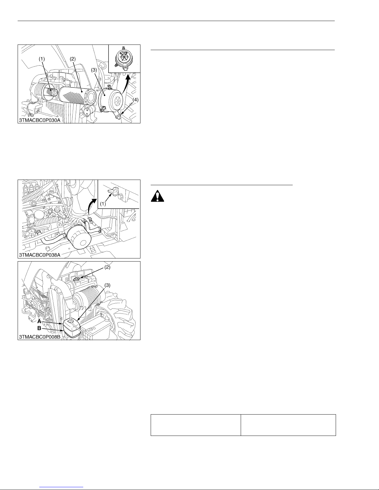
MX5100, WSM
NOTE■
IMPORTANT■
IMPORTANT■
[11] CHECK POINT OF EVERY 1 YEAR
Replacing Air Cleaner Primary Element and Secondary Element
1. Remove the air cleaner cover (3).
2. Replace the air cleaner primary element and the secondary
element.
• Check to see if the evacuator valve is blocked with dust.
• The air cleaner uses a dry element, never apply oil.
• Do not run the engine with filter element removed.
• Be sure to refit the cover the arrow ↑ (on the rear of cover)
upright. If the cover is improperly fitted, evacuator valve will
not function and dust will adhere to the element.
(1) Secondary Element
(2) Primary Element
[12] CHECK POINTS OF EVERY 2 YEARS
Flushing Cooling System and Changing Coolant
G GENERAL
(3) Cover
(4) Evacuator Valve
W10931910
CAUTION
• Do not remove the radiato r cap while coolant is hot. When
cool, slowly rotate cap to the fir st stop and allow sufficient
time for excess pressure to escape before removing the cap
completely.
1. Stop the engine, remove the key and let it cool down.
2. To drain the coolant, open the radiator drain cock (1) and remove
the radiator cap (2). The radiator cap (2) must be removed to
completely drain the coolant.
3. After all coolant is drained, close the drain cock (1).
4. Fill with clean water and cooling system cleaner.
5. Follow directions of the cleaner instruction.
6. After flushing, fill with clean water and anti-freeze until the coolant
level is just be low the radiator cap. Insta ll the radiator cap (2)
securely.
7. Fill with coolant up to “FULL” mark on the recovery tank.
8. Start and operate the engine for few minutes.
9. Stop the engine, remove the key and let cool.
10.Check coolant level of recovery tank and add coolant if
necessary.
11.Properly dispose of used coolant.
• Do not start engine without coolant.
• Use clean, fresh water and anti-freeze to fill the radiator.
• When the anti-freeze is mixed with water, the anti-freeze
mixing ratio must be less than 50 %.
• Securely tighten radiator cap. If the cap is loose or
improperly fitted, water may leak out and the engine could
overheat.
Coolant capacity (with recovery tank)
7.0 L
7.4 U.S.qts
5.8 Imp.qts
(1) Drain Cock
(2) Radiator Cap
(3) Recovery Tank
G-38
A : FULL
B : LOW
W10375100
Page 57
MX5100, WSM
■
G GENERAL
Flushing Cooling System and Changing Coolant (Continued)
■ Anti-Freeze
CAUTION
• When using antifreeze, put on some protection such as
rubber gloves (Antifreeze contains poison.).
• If should drink antifreeze, throw up at once and take medical
attention.
• When antifreeze comes in contact with the skin or clothing,
wash it off immediately.
• Do not mix different types of Antifreeze.
The mixture can produce chemical reaction ca using harmful
substances.
• Antifreeze is extremely flammable and explosive under
certain conditions. Keep fire and children away from
antifreeze.
• When draining fluids from the engine, place some container
underneath the engine body.
• Do not pour waste onto the grounds, down a drain, or into
any water source.
• Also, observe the relevant environmental protection
regulations when disposing of antifreeze.
If it freezes, coolant can damage the cylinders and radiator. If the
ambient temperature fa lls belo w 0 °C (32 °F) o r before a lo ng-term
storage, let out co oling water completely, or mix fr esh water with
long-life coolant and fill the radiator and reserve tank with the
mixture.
1. Long-life coolant (hereafter LLC) comes in several types. Use
ethylene glycol (EG) type for this engine.
2. Before employing LL C-mixed cooli ng water, fil l the radiator with
fresh water and empty it again.
Repeat this procedure 2 or 3 times to clean up the inside.
3. Mixing the LLC
Put the LLC in coolin g water in the percentage (%) for a target
temperature. When mi xing, stir it up well, and then fill into the
radiator.
4. The procedure for the mixing of water and antifreeze differs
according to the make of the antifreeze and the ambient
temperature. Refer to SAE J1034 standard, more specifically
also to SAE J814c.
IMPORTANT
• When the antifreeze is mixed with water, the antifreeze
mixing ratio must be less than 50%.
Vol % Anti-
freeze
40 -24 -12 106 222
50 -37 -34 108 226
* At 1.013 x 1000000 Pa (760mmHg) pressure (atmospheric).
A higher boiling point is obtained by using a radiator pressure cap which permits the
development of pressure within the cooling system.
Freezing Point Boiling Point*
°C °F °C °F
W10385910
G-39
Page 58
MX5100, WSM
NOTE■
G GENERAL
Flushing Cooling System and Changing Coolant (Continued)
5. Adding the LLC
(1) Add only water if the mixture reduces in amount by
evaporation.
(2) If there is a mixture leak, add the LLC of the same
manufacturer and type in the same mixture percentage.
*Never add any long-life coolant of different manufacturer.
(Different brands may hav e different additive components, and
the engine may fail to perform as specified.)
6. When the LLC is mixed, do not employ any radiator cleaning
agent. The LLC contain s anticorros ive agen t. If mixed with the
cleaning agent, sludge may build up, adversely affecting the
engine parts.
7. Kubota’s genuine ling-life coolant has a service life of 2 years. Be
sure to change the coolant every 2 years.
• The above date represent industry standards that
necessitate a minimum glycol c ontent in the concentrates
anti-freeze.
• When the coolant level drops due to evaporation, add water
only to keep the antifreeze mix ing ratio less than 50 %. In
case of leakage, add an tifreeze and water in the specified
mixing ratio before filling in to the radiator.
W10961020
Replacing Fuel Hose
1. Refer to “Checking Fuel Line” shown in page G-27.
W11086610
Replacing Power Steerin g Hose
1. Refer to “Checking Ste ering Oil Line” in “CHECK POINTS OF
EVERY 200 HOURS”.
W11092550
Replacing Radiator Hose (Water Pipes )
1. Refer to “Checking Radiator Hos e an d Hose Clamp” i n “CHECK
POINTS OF EVERY 200 HOURS”.
W11092960
Replacing Intake Air Line
1. Refer to “Checking Intake Air Line” in “CHECK POINTS OF
EVERY 200 HOURS”.
W11093370
G-40
Page 59
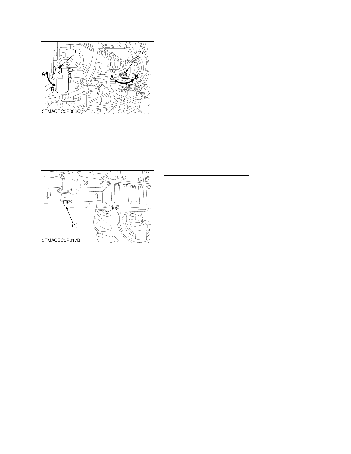
MX5100, WSM
IMPORTANT■
IMPORTANT■
NOTE■
[13] OTHERS
G GENERAL
Bleeding Fuel System
• Air must be removed :
- When the fuel filter or lines are removed.
- When tank is completely empty.
- After the tractor has not been used for a long period of
time.
1. Fill the fuel tank with fuel, and open the fuel cock (1).
2. Open the air vent cock (2) on the fuel injection pump.
3. Start the engine and run for about 30 seconds, and then stop the
engine.
4. Close the air vent cock .
• Always close the air vent cock except for bleeding fuel lines.
Otherwise, engine runs irregularly or stalls frequently.
(1) Fuel Cock
(2) Air Vent Cock
A : Close
B : Open
W10390260
Draining Clutch Housing Water
• The tractor is equipped with split pin plug (1) under the
clutch housing.
• After operating in rain, snow or tractor has been washed,
water may get into the clutch housing.
1. Check it by pushing in the split pin (1).
2. If water enters into the clutc h housing , remove the plug (1) and
drain the water, then reinstall the plug.
(1) Split Pin (Plug)
W10391990
G-41
Page 60
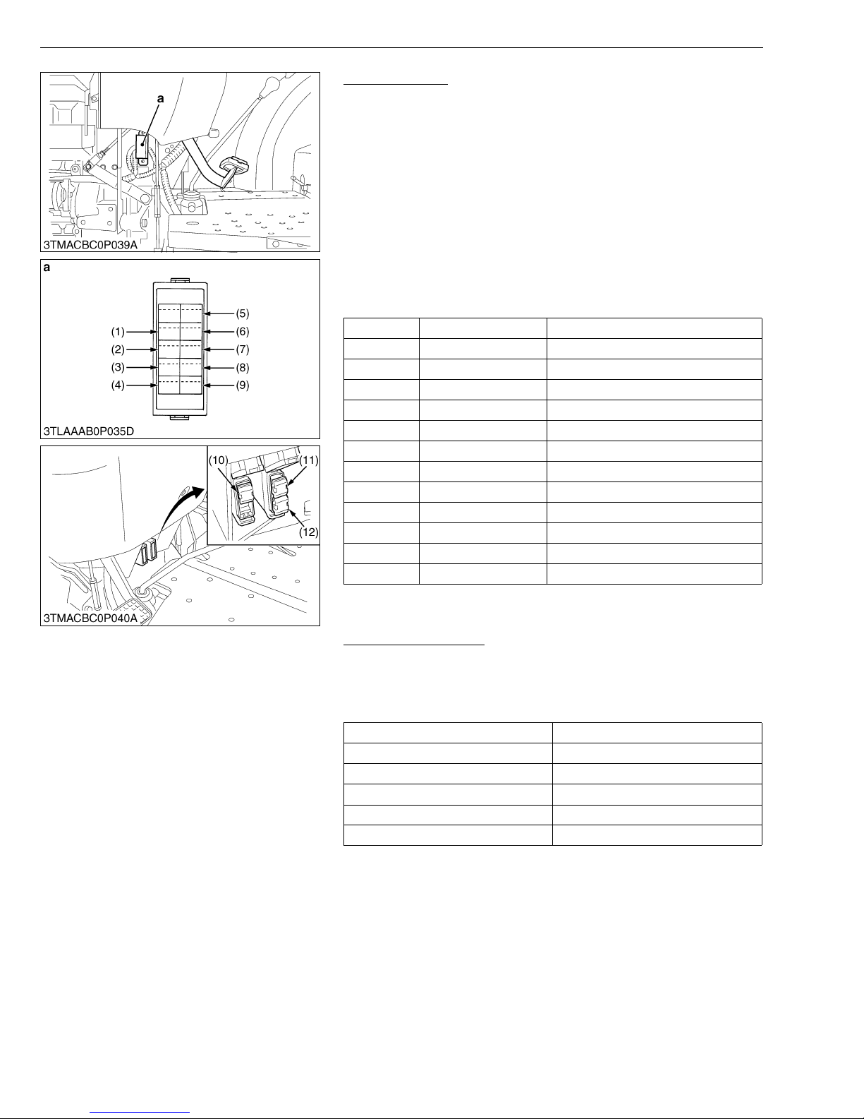
MX5100, WSM
IMPORTANT■
G GENERAL
Replacing Fuse
1. The tractor electri cal sys tem is pro tected from pot ential dama ge
by fuses.
A blown fuse indicates that there is an overload or short
somewhere in the electrical system.
2. If any of the fuses should blow , replace with a new one of the
same capacity.
• Before replacing a blown fuse, determine why the fuse blew
and make any necessary repairs. Failure to follow this
procedure may result in serious damage to the tractor
electrical system. Refer to “TRABLESHOOTING” section of
this manual.
■ Protected Circuit
Fuse No. Capacity Protected circuit
(1) 10 A Working Light
(2) 10 A Panel
(3) 5 A Head Light
(4) 5 A Key Stop
(5) 5 A Glow Lamp
(6) 5 A Starter Relay
(7) 15 A Head Lamp Relay (Hi)
(8) 15 A Head Lamp Relay (Lo)
(9) 15 A Hazard
(10) 50 A Key Switch
(11) 50 A Main
(12) 30 A Key Stop
a : Fuse Box
W10393150
Replacing Light Bu l b
1. Head lights and rear combination lights :
Take the bulb out of the light body and replace with a new one.
2. Other lights :
Detach the lens and replace the bulb.
Light Capacity
Head Light 60 W / 55W
Tail Light 8 W
Turn Signal / Hazard Light (Rear) 23 W
Turn Signal / Hazard Light (Rear) 27 W
Instrument Panel Light 1.7 W
W10396590
G-42
Page 61
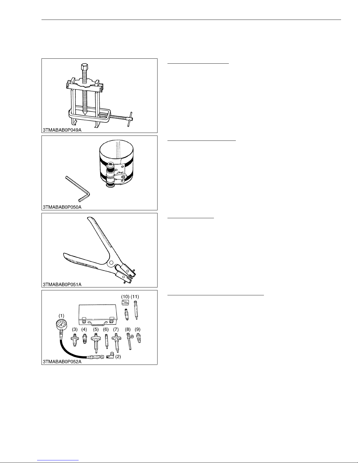
MX5100, WSM
8. SPECIAL TOOLS
[1] SPECIAL TOOLS FOR ENG INE
Special Use Puller Set
Code No.: 07916-09032
Application: Use exclusively for pulling out bearing, gears and other
Piston Ring Compressor
Code No.: 07909-32111
Application: Use exclusively for pushing in the piston with piston
G GENERAL
parts with ease.
W10240500
rings into the cylinder.
W10241000
Piston Ring Tool
Code No.: 07909-32121
Application: Use exclusively for removing or installing the piston ring
with ease.
W10241500
Diesel Engine Compression Tester
Code No.: 07909-30208 (Assembly) 07909-31251 (G)
07909-30934 (A to F) 07909-31271 (I)
07909-31211 (E and F) 07909-3128 1 (J)
07909-31231 (H)
Application: Use to measure diesel engine compression and
diagnostics of need for major overhaul.
(1) Gauge
(2) L Joint
(3) Adaptor A
(4) Adaptor B
(5) Adaptor C
(6) Adaptor E
(7) Adap tor F
(8) Adap tor G
(9) Adap tor H
(10) Adaptor I
(11) Adaptor J
W10242000
G-43
Page 62
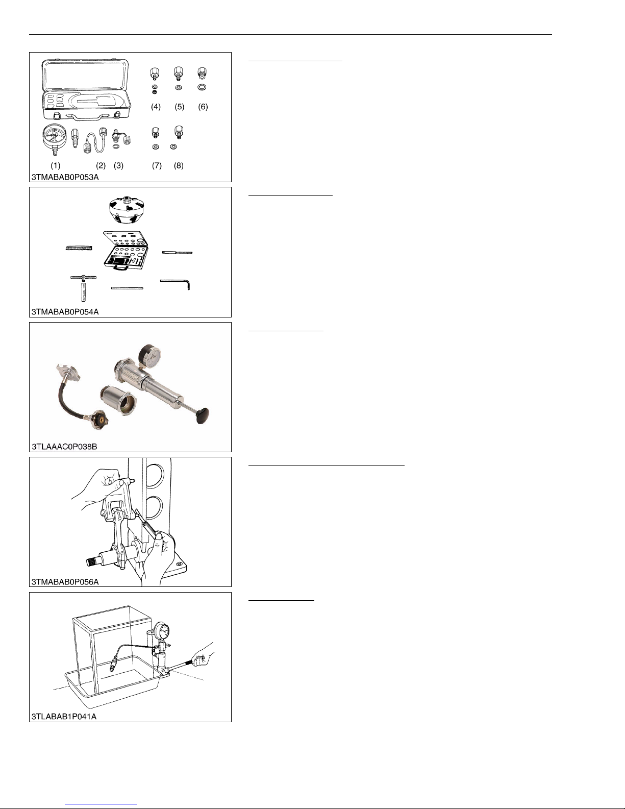
MX5100, WSM
G GENERAL
Oil Pressure Tester
Code No.: 079 16-32 032
Application: Use to measure lubricating oil pressure.
(1) Gauge
(2) Cable
(3) Threaded Joint
(4) Adaptor 1
(5) Adaptor 2
(6) Adaptor 3
(7) Adaptor 4
(8) Adaptor 5
Valve Seat Cutter
Code No.: 079 09-33 102
Application: Use to reseat valves.
Angle: 0.785 rad (45°)
0.262 rad (15°)
Diameter: 28.6 mm (1.126 in.) 38.0 mm (1.496 in.)
31.6 mm (1.244 in.) 41.3 mm (1.626 in.)
35.0 mm (1.378 in.) 50.8 mm (2.000 in.)
W10243180
W10244580
Radiator Tester
Code No.: 079 09-31 551
Application: Use to check of radiator ca p pressur e, and l eaks from
cooling system.
W10245320
Connecting Rod Alignment Tool
Code No.: 079 09-31 661
Application: Use to check the connecting rod alignment.
Applicable: Connecting rod big end I.D.
range 30 to 75 mm (1.18 to 2.95 in.) dia.
Connecting rod length
65 to 300 mm (2.56 to 11.81 in.)
W10245830
Nozzle Tester
Code No.: 079 09-31 361
Application: Use to check the fuel injection pressure and spray
pattern of nozzle.
Measuring: 0 to 50 MPa
range (0 to 500 kgf/cm
2
, 0 to 7000 psi)
W11026450
G-44
Page 63
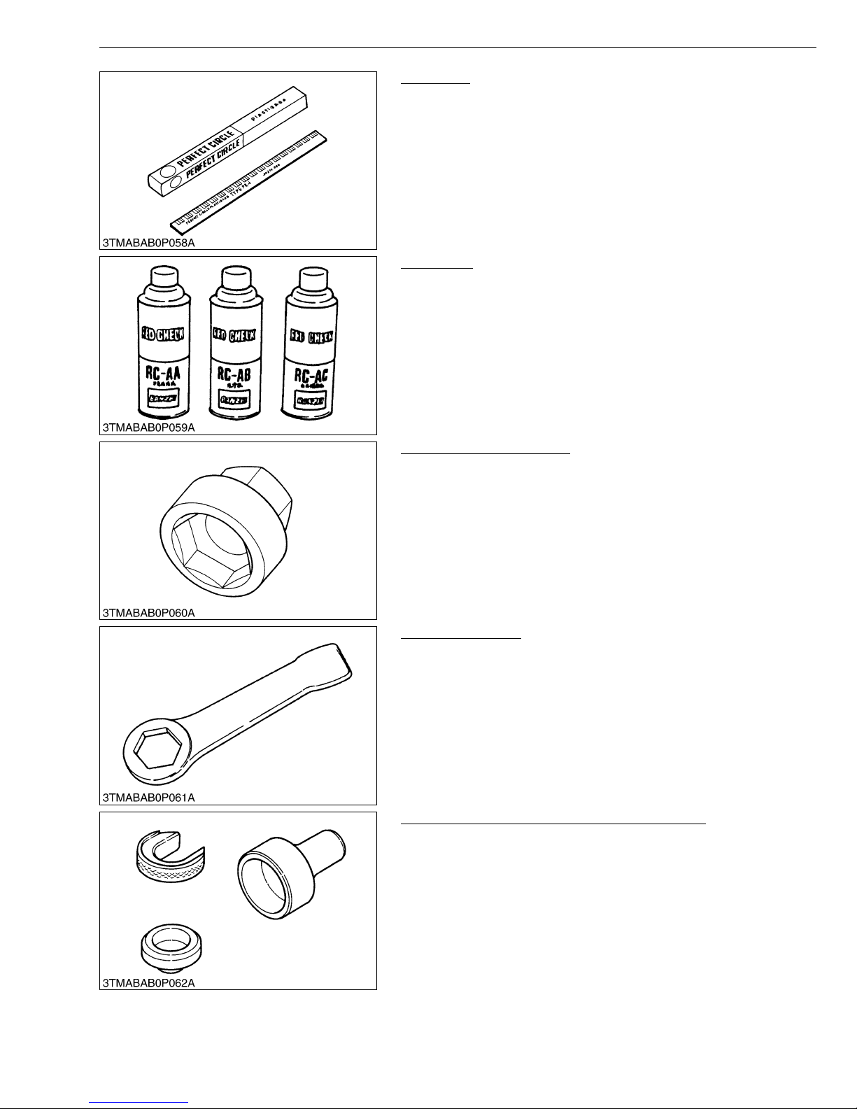
MX5100, WSM
G GENERAL
Plastigage
Code No.: 07909-30241
Application: Use to check the oil clearance between crankshaft and
bearing, etc.
Measuring: Green.... 0.025 to 0.076 mm (0.001 to 0.003 in.)
range Red ....... 0.051 to 0.152 mm (0.002 to 0.006 in.)
Blue....... 0.102 to 0.229 mm (0.004 to 0.009 in.)
W11030320
Red Check
Code No.: 07909-31371
Application: Use to check cracks on cylinder head, cy linder block,
etc.
W11034030
Crankshaft Nut Socket 46
Code No.: 07916-30821
Application: Use exclusively for removing or installing the
crankshaft nut.
W10443610
Socket Wrench 46
Code No.: 07916-30901
Application: Use exclusively for removing or installing the
crankshaft nut.
W10444600
Auxiliary Socket For Fixing Crankshaft Sleeve
Code No.: 07916-32091
Application: Use to fix the crankshaft sleeve of the diesel engine.
W10771140
G-45
Page 64

MX5100, WSM
NOTE■
• The following special tools are not provided, so make them referring to the figure.
Valve Guide Replacing Tool
Application: Use to press out and press fit the valve guide.
A 20 mm dia. (0.79 in. dia.)
B 11.7 to 11.9 mm dia. (0.460 to 0.468 in. dia.)
C 6.5 to 6.6 mm dia. (0.256 to 0.259 in. dia.)
D 225 mm (8.86 in.)
E 70 mm (2.76 in.)
F 45 mm (1.77 in.)
G 25 mm (0.98 in.)
H 5 mm (0.197 in.)
I 6.7 to 7.0 mm dia. (0.263 to 0.275 in. dia.)
J 20 mm dia. (0.787 in. dia.)
K 12.5 to 12.8 mm dia. (0.492 to 0.504 in. dia.)
L 8.9 to 9.1 mm (0.350 to 358 in.)
C1 Chamfer 1.0 mm (0.039 in.)
C2 Chamfer 2.0 mm (0.079 in.)
C0.3 Chamfer 0.3 mm (0.012 in.)
Bushing Replacing Tools
Application: Use to press out and to press fit the bushing.
(1) For small end bushing
A 162 mm (6.38 in.)
B 35 mm (1.38 in.)
C 27 mm (1.06 in.)
D 35 mm dia. (1.38 in. dia.)
E 27.90 to 27.95 mm dia. (1.098 to 1.100 in. dia.)
F 25.00 to 25.01 mm dia. (0.984 to 0.985 in. dia.)
(2) For idle gear bushing
A 175 mm (6.89 in.)
B 40 mm (1.57 in.)
C 38 mm (1.49 in.)
D 45 mm dia. (1.77 in. dia.)
E 41.90 to 41.95 mm dia. (1.650 to 1.652 in. dia.)
F 37.95 to 37.97 mm dia. (1.494 to 1.495 in. dia.)
Flywheel Stopper
Application: Use to loosen and tighten the flywheel screw.
A 200 mm (7.87 in.)
B 20 mm (0.79 in.)
C 30 mm (1.18 in.)
D 8 mm (0.31 in.)
E 10 mm dia. (0.39 in. dia.)
G GENERAL
W10250170
W10255000
W10259480
G-46
Page 65
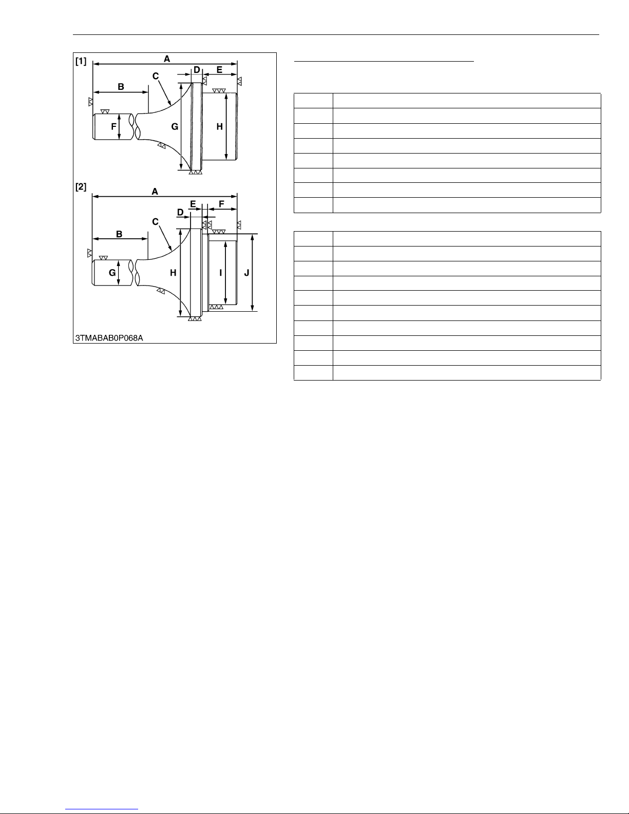
MX5100, WSM
G GENERAL
Crankshaft Bearing 1 Replacing Tool
Application: Use to press out and press fit the crankshaft bearing 1.
1. Extracting tool
A 135 mm (5.31 in.)
B 72 mm (2.83 in.)
C R40 mm (R1.57 in.)
D 10 mm (0.39 in.)
E 20 mm (0.79 in.)
F 20 mm dia. (0.79 in. dia.)
G 56.8 to 56.9 mm dia. (2.236 to 2.240 in. dia.)
H 51.8 to 51.9 mm dia. (2.039 to 2.043 in. dia.)
2. Inserting tool
A 130 mm (5.12 in.)
B 72 mm (2.83 in.)
C R40 mm (R1.57 in.)
D 9 mm (0.35 in.)
E 4 mm (0.16 in.)
F 20 mm (0.79 in.)
G 20 mm dia. (0.79 in. dia.)
H 68 mm dia. (2.68 in. dia.)
I 51.8 to 51.9 mm dia. (2.039 to 2.043 in. dia.)
J 56.8 to 56.9 mm dia. (2.236 to 2.240 in. dia.)
W10261390
G-47
Page 66
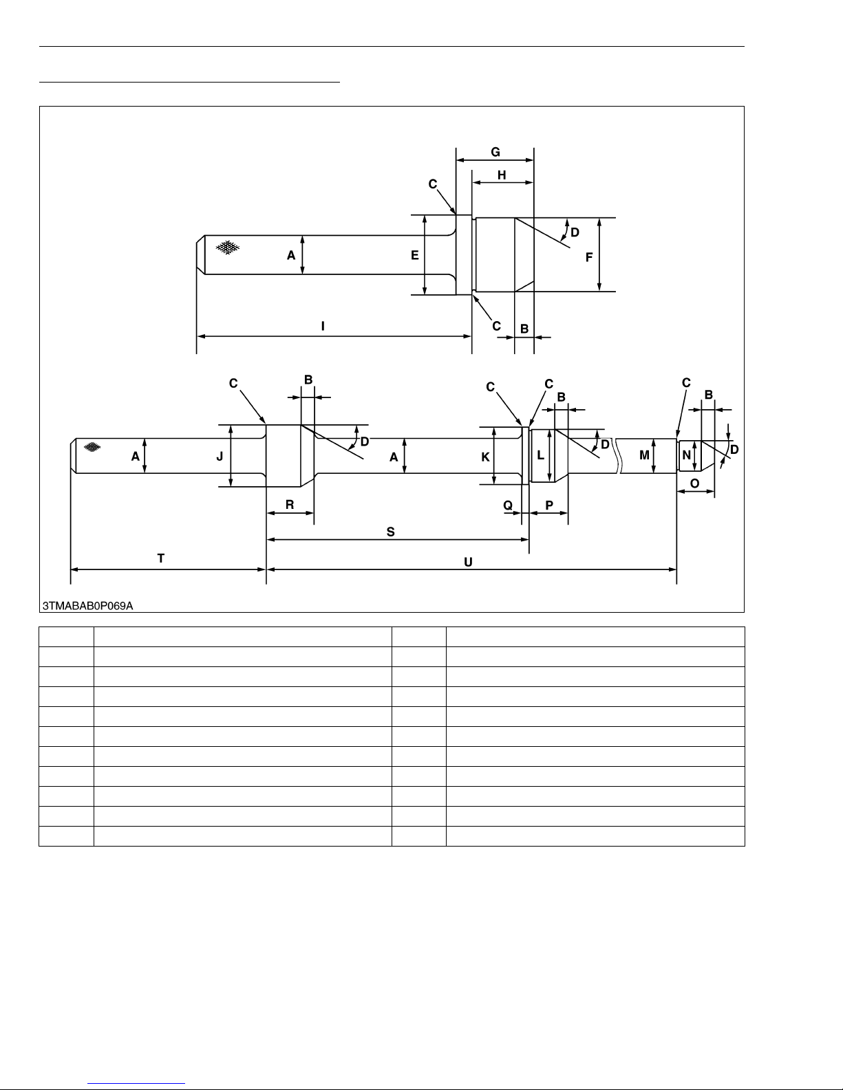
MX5100, WSM
Balancer Metal Replacing Tool (for Removing)
Application: Use to remove the metal bearing.
G GENERAL
A 25 mm (0.98 in. dia.) L 41.934 to 41.950 mm dia. (1.6509 to 1.6516 in. dia.)
B 10 mm (0.39 in.) M 24.959 to 24.980 mm dia. (0.9826 to 0.9835 in. dia.)
C Chamfer 0.3 mm (0.01 in.) N 21.947 to 21.960 mm dia. (0.8641 to 0.8646 in. dia.)
D 0.52 rad (30 °) O 28 mm (1.10 in.)
E 46.950 to 46.975 mm dia. (1.8484 to 1.8494 in. dia.) P 29 mm (1.14 in.)
F 43.934 to 43.950 mm dia. (1.7297 to 1.7303 in. dia.) Q 5 mm (0.20 in.)
G 41 mm (1.61 in.) R 36 mm (1.42 in.)
H 32.5 mm (1.28 in.) S 195.25 to 195.75 mm (7.687 to 7.707 in.)
I 148.5 mm (5.85 in.) T 145 mm (5.71 in.)
J 46.50 to 46.75 mm dia. (1.831 to 1.841 in. dia.) U 384.75 to 385.25 mm (15.148 to 15.167 in.)
K 44.950 to 44.975 mm dia. (1.7697 to 1.7707 in. dia.)
G-48
Page 67
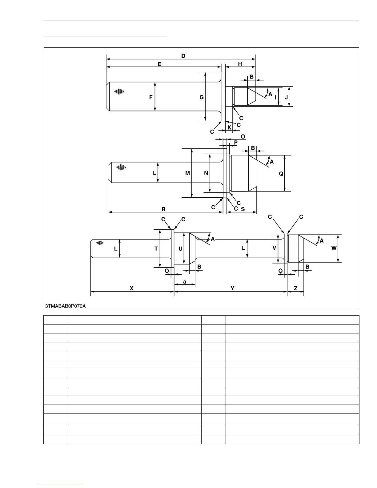
MX5100, WSM
Balancer Metal Replacing Tool (for Fitting)
Application: Use to press fit the metal bearing.
G GENERAL
A 0.52 rad (30 °) O 5 mm (0.20 in.)
B 10 mm (0.39 in.) P 3.3 to 3.7 mm (0.130 to 0.146 in.)
C Chamfer 0.3 mm (0.01 in.) Q 43.934 to 43.950 mm dia. (1.7297 to 1.7303 in. dia.)
D 182 mm (7.16 in.) R 140 mm (5.51 in.)
E 140 mm (5.51in.) S 36 mm (1.42 in.)
F 35 mm dia. (1.38 in dia.) T 60 mm dia. (2.36 in. dia.)
G 60 mm dia. (2.36 in dia.) U 46.950 to 46.975 mm dia. (1.8484 to 1.8494 in. dia.)
H 37 mm (1.46 in.) V 44.950 to 44.975 mm dia. (1.7697 to 1.7707 in. dia.)
I 21.947 to 21.960 mm dia. (0.8641 to 0.8646 in. dia.) W 41.934 to 41.950 mm dia. (1.6509 to 1.6516 in. dia.)
J 24.959 to 24.980 mm dia. (0.9826 to 0.9835 in. dia.) X 145 mm (5.71 in.)
K 8.8 to 9.2 mm (0.346 to 0.362 in.) Y 195.25 to 195.75 mm (7.687 to 7.707 in.)
L
25 mm dia. (0.98 in. dia.)
M
60 mm dia. (2.36 in. dia.)
N
46.950 to 46.975 mm dia. (1.8484 to 1.8494 in. dia.)
G-49
Z
a
29 mm (1.14 in.)
36 mm (1.42 in.)
Page 68
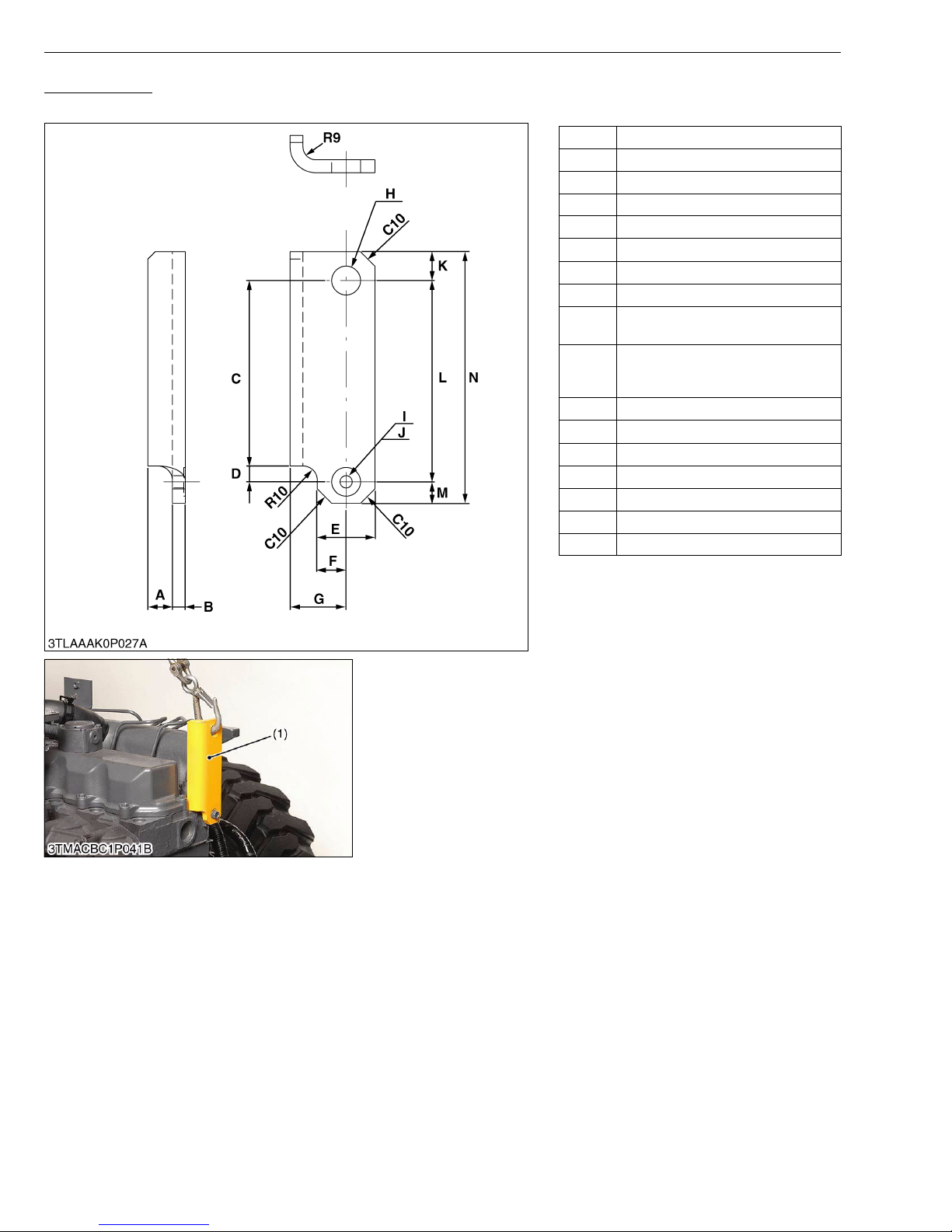
MX5100, WSM
Engine Hook 1
Application: Use for hooking the V2403-M-T engine. Use this engine hook 1 with the engine hook 2.
A 17 mm (0.67 in.)
B 9 mm (0.35 in.)
C 129 mm (5.08 in.)
D 10.8 to 11.2 mm (0.426 to 0.440 in.)
E 40 mm (1.6 in.)
F 20 mm (0.79 in.)
G 39 mm (1.5 in.)
H 20 mm Hole (0.79 in. Hole)
8.50 to 8.80 mm Drilled hole
I
(0.335 to 0.346 in. Drilled hole)
20 mm Spot-faced hole 1 mm deep
J
(0.79 in. Spot-faced hole 0.04 in.
deep)
K 20 mm (0.79 in.)
L 140 mm (5.51 in.)
M 15 mm (0.59 in.)
N 175 mm (6.89 in.)
C10 Chamfer 10 mm (0.39 in.)
R9 Radius 9.0 mm (0.35 in.)
R10 Radius 10 mm (0.39 in.)
G GENERAL
W1018612
(1) Engine Hook 1
W1111510
G-50
Page 69
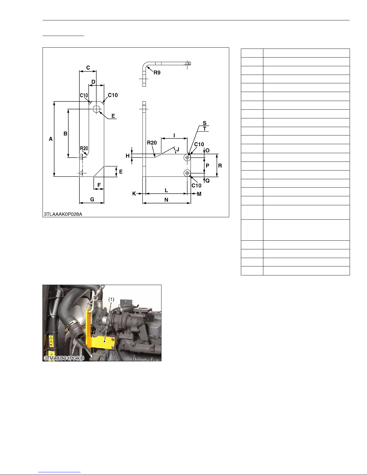
MX5100, WSM
Engine Hook 2
Application: Use for hooking the V2403-M-T engine. Use this engine hook 2 with the engine hook 1.
A 217 mm (8.54 in.)
B 140 mm (5.51 in.)
C 49 mm (1.9 in.)
D 44 mm (1.7 in.)
E 20 mm Hole (0.79 in. Hole)
F 30 mm (1.2 in.)
G 71 mm (2.8 in.)
H 10 mm (0.39 in.)
I 85 mm (3.3 in.)
J 0.52 rad (30 °)
K 9.0 mm (0.35 in.)
L 120 mm (4.72 in.)
M 10 mm (0.39 in.)
N 139 mm (5.12 in.)
O 10 mm (0.39 in.)
P 44.7 to 45.3 mm (1.76 to 1.78 in.)
Q 10 mm (0.39 in.)
R 65 mm (2.6 in.)
2 × 8.50 to 8.80 mm Drilled hole
S
(2 × 0.335 to 0.346 in. Drilled hole)
20 mm Spot-faced hole 1 mm deep
T
(0.79 in. Spot-faced hole 0.04 in.
deep)
C10 Cham fer 10 mm (0.39 in.)
R9 Radius 9.0 mm (0.35 in.)
R10 Radius 10 mm (0.39 in.)
R20 Radius 20 mm (0.79 in.)
(1) Engine Hook 2
G GENERAL
W1078963
W1111678
G-51
Page 70
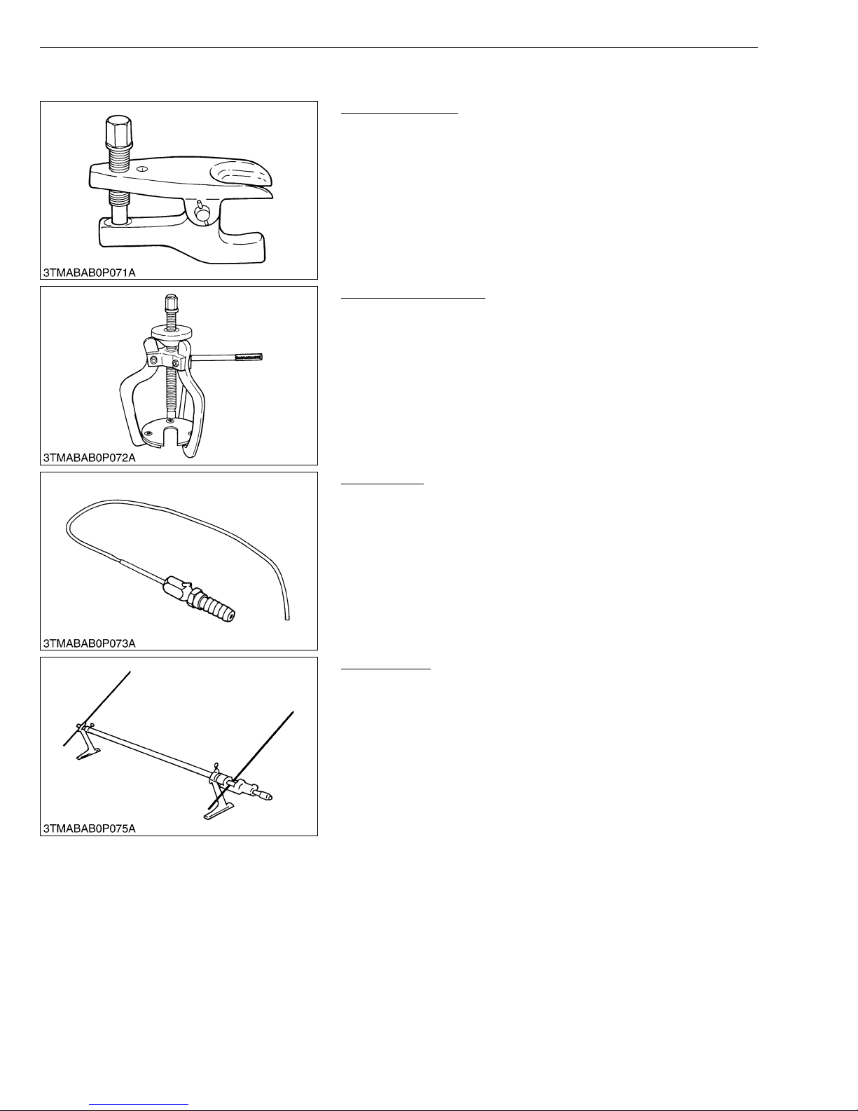
MX5100, WSM
[2] SPECIAL TOOLS FOR TRACTOR
Tie-rod End Lifter
Code No.: 079 09-39 051
Application: Use for removing the tie-rod end with ease.
Steering Wheel Puller
Code No.: 079 16-51 090
Application: Use for removing the steering wheel without damaging
G GENERAL
W10264720
the steering shaft.
W10265330
Injector CH3
Code No.: 079 16-52 501
Application: Use for injecting calcium chloride solution into, and
removing it from, rear wheel.
W10265850
Toe-in Gauge
Code No.: 079 09-31 681
Application: This allows easy measurement of toe-in for all machine
models.
W10266890
G-52
Page 71
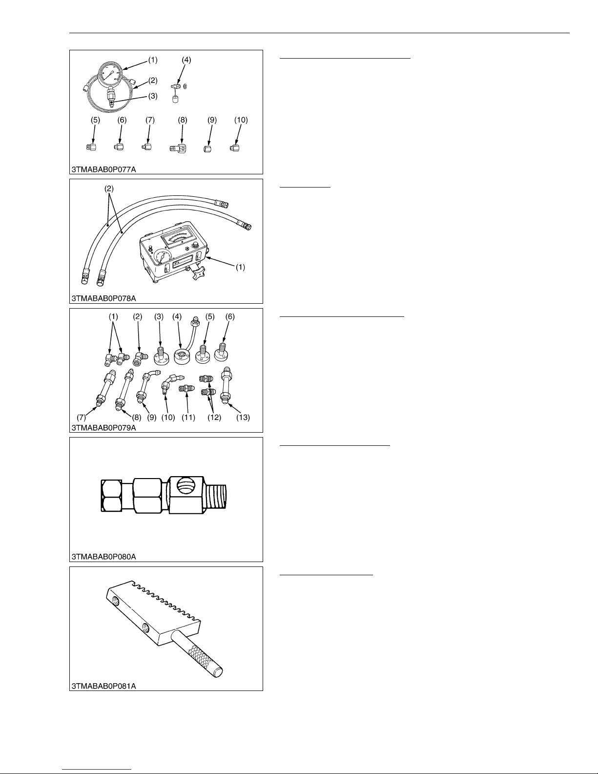
MX5100, WSM
G GENERAL
Relief Valve Pressure Tester
Code No.: 07916-50045
Application: This allows easy measurement of relief set pressure.
(1) Gauge (07916-50322)
(2) Cable (07916-50331)
(3) Threaded Joint (07916-50401)
(4) Threaded Joint (07916-50341)
(5) Adaptor B (M18 × P1.5)
(07916-50361)
(6) Adap tor C (PS3/8) (07916-50371)
(7) Adap tor D (PT1/8) (07916-50381)
(8) Adap tor E (PS3/8) (07916-50392)
(9) Adap tor F (PF1/2) (07916-62601)
(10) Adaptor 58 (PT1/4) (07916-52391)
W10267410
Flow Meter
Code No.: 07916-52791 (Flow Meter)
07916-52651 (Hydraulic Test Hose)
Application: This allows easy testing of hydraulic system.
(1) Flow Meter (2) Hydraulic T es t Hose
W10313180
Adaptor Set for Flow Meter
Code No.: 07916-54031
Application: Use for testing the hydraulic system.
(1) Adaptor 52
(2) Adaptor 53
(3) Adaptor 54
(4) Adaptor 61
(5) Adaptor 62
(6) Adaptor 63
(7) Adaptor 64
(8) Adap tor 65
(9) Adap tor 66
(10) Adaptor 67
(11) Adaptor 68
(12) Adaptor 69
(13) Hydraulic Adaptor 1
W10313960
Power Steering Adapter
Code No.: 07916-54021
Application: Use for measuring the relief valve se tting pressu re for
power steering.
W10442870
Pinion Locking Tool
Code No.: 07916-52311
Application: Use for preventing the shaft from turning when
removing or tighten a bevel pinion shaft staking nut.
W10445520
G-53
Page 72
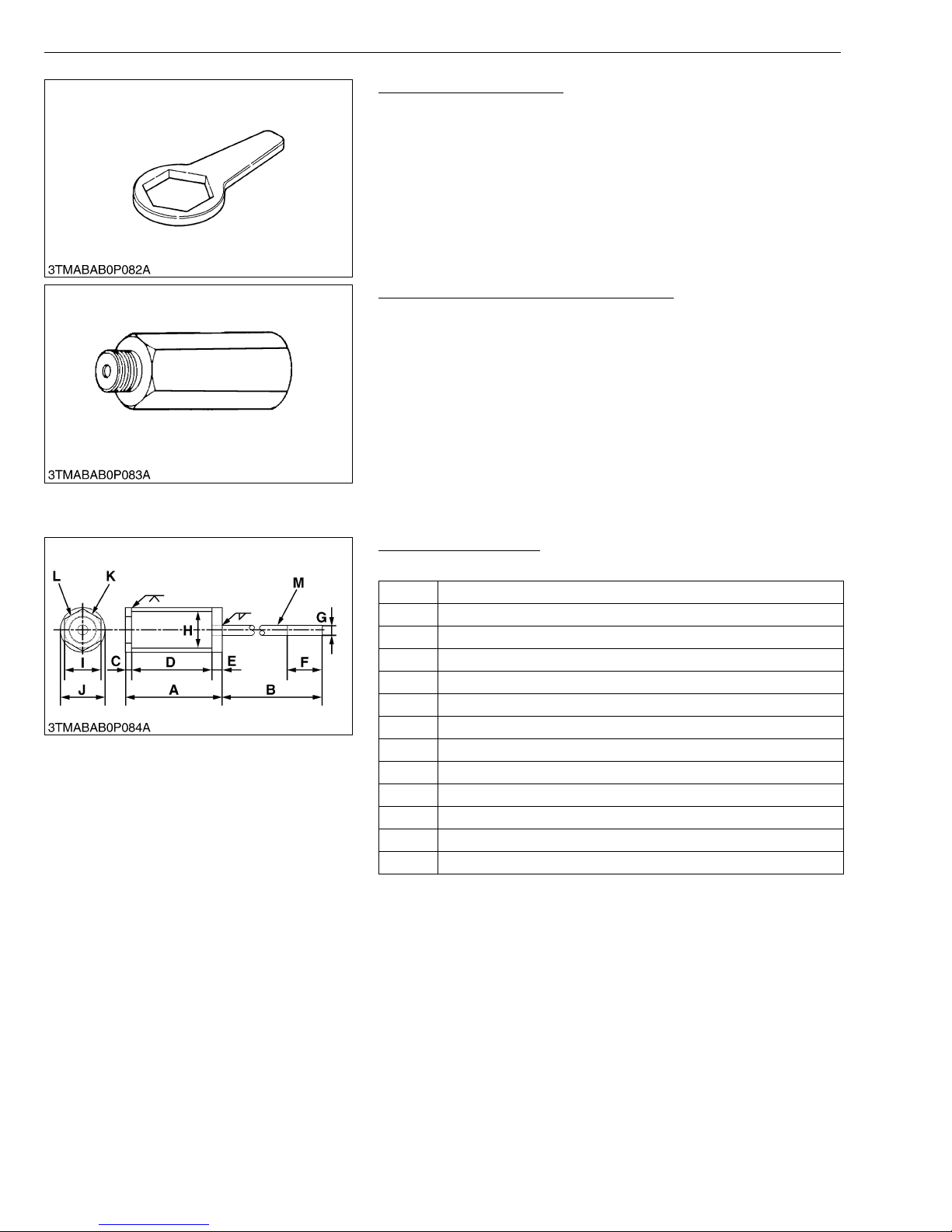
MX5100, WSM
NOTE■
G GENERAL
Rear Axle Nut Wrench 71
Code No.: 079 16-52 531
Application: Use for removing and installing a rear axle nut.
W10446460
Relief Valve Setting Pressure Adaptor G
Code No.: 079 16-52 751
Application: This offers easy measurement of relief valve setting
pressure from the hy draulic couple r. This is avail able
with the relief valve setting pressure tester.
W10623960
• The following special tools are not provided, so make them referring to the figure.
Pinion Shaft Remover
Application: Use for removing a pinion shaft.
A 106 mm (4.17 in.)
B 350 mm (13.78 in.)
C 6 mm (0.24 in.)
D 90 mm (3.54 in.)
E 10 mm (0.39 in.)
F 40 mm (1.57 in.)
G 10 mm (0.39 in.)
H 35.6 mm (1.40 in.)
I 36 mm (1.42 in.)
J 41.6 mm (1.64 in.)
K Part code No. 3A201-4130 nut
L M27 × P1.5
M M10 × P1.25
W10315930
G-54
Page 73
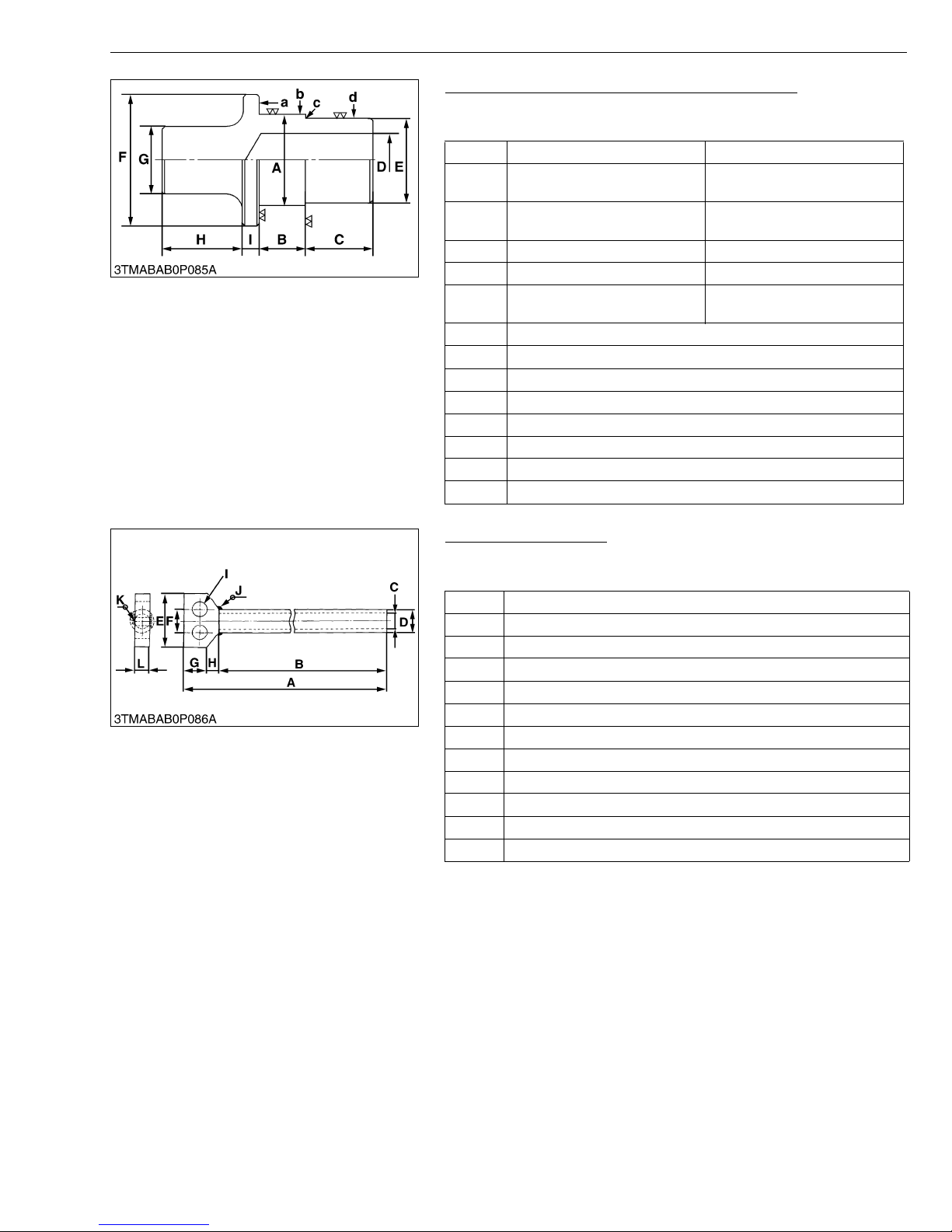
MX5100, WSM
G GENERAL
Hydraulic Arm Shaft Bushing Press-Fitting Tool
Application: Use for replacing the hydr aulic arm shaft bushin gs in
the hydraulic cylinder body.
Right Left
54.7 to 54.9 mm
A
(2.1535 to 2.1614 in.)
24.5 to 25.5 mm
B
(0.9646 to 1.0039 in.)
C 40 mm (1.57 in.) 40 mm (1.57 in.)
D 32 mm (1.26 in.) 30 mm (1.18 in.)
49.7 to 49.9 mm
E
(1.9567 to 1.9646 in.)
F 70 mm dia. (2.76 in. dia.)
G 40 mm dia. (1.57 in. dia.)
H 50 mm (1.97 in.)
I 10 mm (0.39 in.)
a 6.3 μm (250 μin.)
b 6.3 μm (250 μin.)
c 6.3 μm (250 μin.)
d 6.3 μm (250 μin.)
49.7 to 49.9 mm
(1.9567 to 1.9646 in.)
21.5 to 22.5 mm
(0.8465 to 0.8858 in.)
44.7 to 44.9 mm
(1.7598 to 1.7677 in.)
W10316550
Draft Control Test Bar
Application: Use for checking the lift range and floating range of
hydraulic draft contro l.
A 1045 mm (41.14 in.)
B 1000 mm (29.37 in.)
C 20 mm dia. (0.79 in. dia.)
D 30 mm dia. (1.18 in. dia.)
E 90 mm (3.54 in.)
F 30 mm (1.18 in.)
G 30 mm (1.18 in.)
H 15 mm (0.59 in.)
I 20 mm dia. (0.79 in. dia.)
J Weld all around
K Weld all around
L 20 mm (0.79 in.)
W10625190
G-55
Page 74
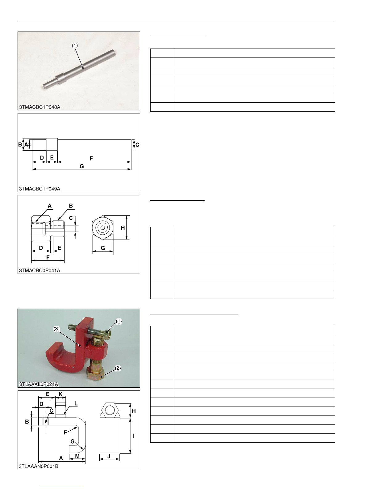
MX5100, WSM
G GENERAL
Clutch Center Tool
Application: Use for removing and installing the clutch assembly.
A 18.8 mm dia. (0.74 in. dia.)
B 31.7 mm dia. (1.25 in. dia.)
C 25.0 mm dia. (0.98 in. dia.)
D 50.0 mm (1.97 in.)
E 26.0 mm (1.02 in.)
F 200.0 mm (7.87 in.)
G 276.0 mm (10.87 in.)
(1) Clutch Center Tool
W11146660
Adaptor C (PS 3/8)
Code No.: 079 16-50 371
Application: Use for measuring HST and PTO clutch operating
pressure.
A PS 1/4
B PT 3/8
C 7 mm dia. (0.28 in. dia.)
D 20 mm (0.79 in.)
E 3 mm (0.12 in.)
F 35 mm (1.38 in.)
G 24 mm (0.94 in.)
H 27.7 mm (1.09 in.)
W11017660
Front Axle Rocking Restrictor
Application: Use for restricting front axle rocking.
A 7 0 mm (2 .8 i n .)
B 11 mm (0.43 in)
C M8 x P1.25
D 15 mm (0.59 in.)
E 30 mm (1.2 in.)
F R5 mm (R0.2 in.)
G R15 mm (R0.59 in.)
H 22 mm (0.87 in.)
I 52 mm (2.0 in.)
J 30 mm ( 1 .2 i n .)
K 10 mm (0.39 in.)
L 25 mm (0.98 in.)
M 25 mm (0.98 in.)
(1) Screw M8 x P1.25 x L50 mm (2 in.)
(2) Screw M14 x P1.5 x L50 mm (2 in.)
G-56
(3) Front Axle Rocking Restrictor
W10410410
Page 75
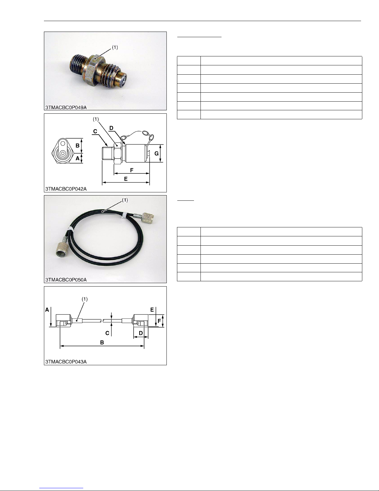
MX5100, WSM
G GENERAL
Threaded Joint
Code No.: 07916-50341
Application: Use for measuring PTO clutch operating pressure.
A 10 mm (0.39 in.)
B 16.2 mm (0.64 in.)
C PS 1/4
D M16 × 1.5
E 49 mm (1.93 in.)
F 37 mm (1.46 in.)
G 18 mm dia. (0.71 in. dia.)
(1) Threaded Joint
W11020690
Cable
Code No.: 07916-50330
Application: Use for measuring three point system relief valve
operating pressure, etc..
A M16 × 1.5
B 1000 mm (39.37 in.)
C 45 mm dia. (0.18 in. dia.)
D 21 mm (0.83 in.)
E M16 × 1.5
F 18 mm dia. (0.71 in. dia.)
(1) Cable
W11117500
G-57
Page 76
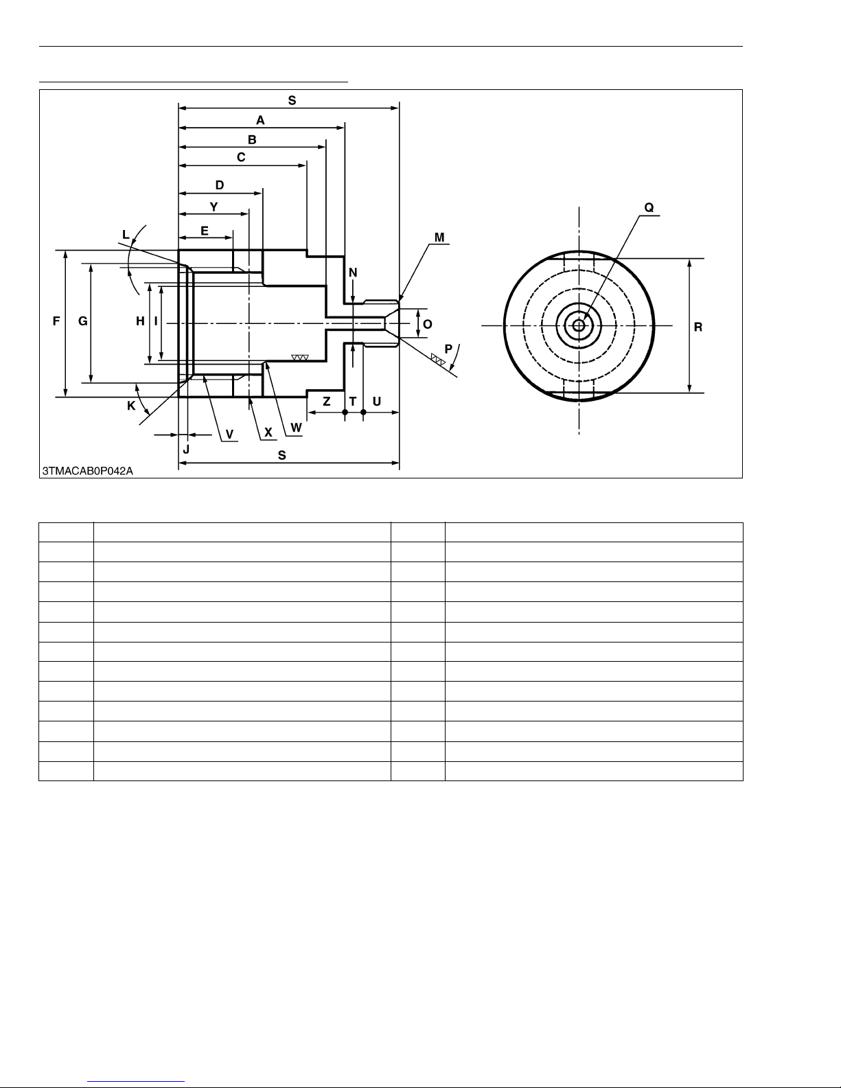
MX5100, WSM
Cylinder Safety Valve Setting Pressure Adaptor
G GENERAL
Application: Use for setting the safety valve to the nozzle tester to measure cracking pressure and check oil tightness
of the safety valves.
A 45 mm (1.77 in.) N 10 mm dia. (0.39 in. dia.)
B 40 mm (1.58 in.) O 7.5 mm dia. (0.3 in. dia.)
C 35 mm (13.8 in.) P 1.05 rad (60 °)
D 23 to 23.3 mm (0.9055 to 0.9713 in.) Q 3 mm dia. (1.18 in. dia.)
E 16 mm dia. (0.63 in. dia.) R 36 mm (1.18 in.)
F 40 mm dia. (1.58 in. dia.) S 60 mm (2.36 in.)
G 32.4 to 32.7 mm dia. (1.2756 to 1.2874 in. dia.) T 5 mm (0.20 in.)
H 21 mm dia. (0.83 in. dia.) U 10 mm (0.39 in.)
I 20 to 20.05 mm dia. (0.7874 to 0.7894 in. dia.) V M30 × P1.5
J 2.5 to 2.59 mm (0.0984 to 0.1097 in.) W 0.52 rad (30 °)
K 0.79 rad (45 °) X 8 mm dia. (0.32 in. dia.)
L 0.26 rad (15 °) Y 19 mm (0.75 in.)
M M12 × P1.5 Z 10 mm (0.39 in.)
G-58
Page 77
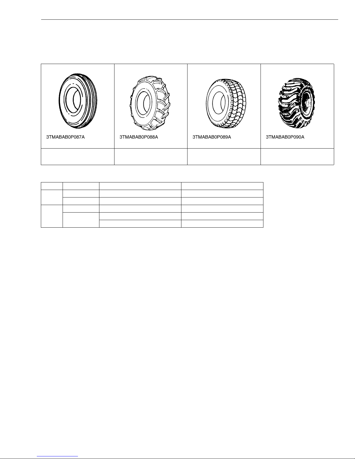
MX5100, WSM
9. TIRES
[1] TYPES OF TIRE
The following tires can be mounted.
G GENERAL
Farm tire
(Front Tire of 2WD only)
Type of tire Front Rear
2WD
4WD
Farm Tire 7.5L – 15, 6PR or 9.5L–15, 6PR 13.6 – 28, 4PR or 14.9 – 26, 4PR
Turf Tire 29 × 12.50 – 15, 4PR 44 × 18 – 20, 6PR
Farm Tire 9.5 – 16, 4PR 13.6 – 28, 4PR or 14.9 – 26, 4PR
Industrial Tire
Farm Tire Turf Tire Industrial Tire
W10522100
12 – 16.5, 6PR 17.5L – 24, 6PR
305R343, 2PR 610R470, 6PR
G-59
Page 78
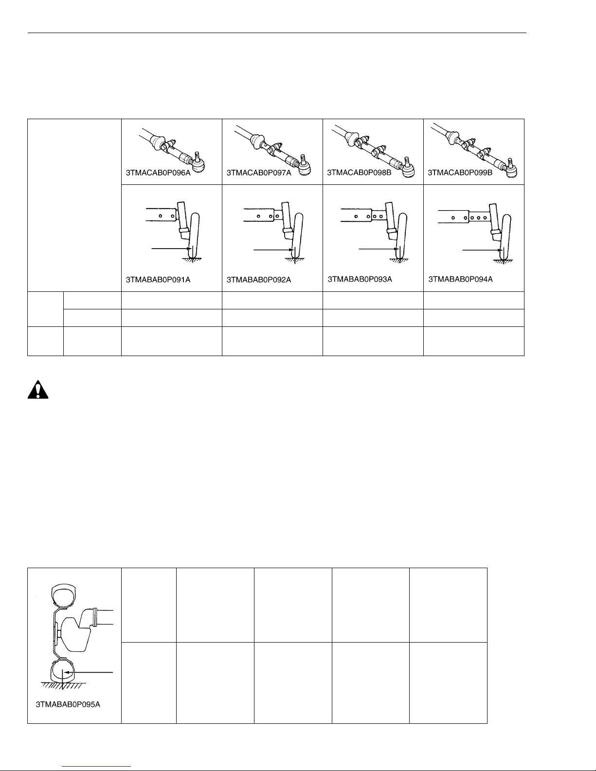
MX5100, WSM
IMPORTANT■
[2] TREADS ADJUSTMENT
(1) Front Wheels
(A) 2WD Type
With 2WD models, the front tread can be adjusted in 4 steps.
Models
G GENERAL
Farm
Turf
• When working on sl opes or working wit h trailer, set the wh eel tread as wide as pr actice for the job for
maximum stability.
To change the tread
1. Lift the front of the tractor with a jack.
2. Remove the front axle mounting screws and the tie rod mounting screws.
3. Move the front axle (right and left) to the desired position, and tighten them with the screws.
• After tread adjustment, adjust toe-in.
Toe-in: All models 2 to 8 mm (0.08 to 0.31 in.)
• The front width for the front loader application on 2WD models should not be greater than 1215 mm (47.8
in.).
7.5L-15 1280 mm (50.4 in.) 1380 mm (54.3 in.) 1480 mm (58.3 in.) 1580 mm (62.2 in.)
9.5L-15 1255 mm (49.4 in.) 1355 mm (53.3 in.) 1455 mm (57.3 in.) 1555 mm (61.2 in.)
29 x 12.5-
15
CAUTION
1315 mm (51.8 in.) 1415 mm (55.7 in.) 1515 mm (59.6 in.) 1615 mm (63.6 in.)
W1050874
(B) 4WD Type
Front tread can not be adjusted.
Tire 9.5-16
Tread 1325 mm
(52.2 in.)
Farm
12-16.5
Industrial
1325 mm
(52.2 in.)
G-60
29 × 12.5–15
Turf
1305 mm
(51.4 in.)
305R343
Industrial
1440 mm
(56.69 in.)
W10527070
Page 79
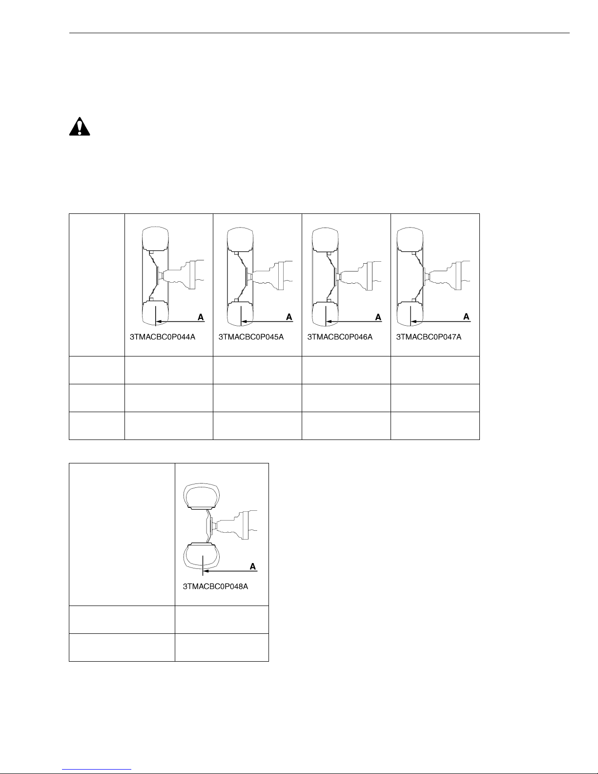
MX5100, WSM
IMPORTANT■
G GENERAL
(2) Rear Wheels
Rear tread can be adjusted in 5 steps depending on the model.
To change the tread
1. Remove the wheel rim and / or disk mounting bolts.
2. Change the position of the rim and / or disk (ring and left) to the desired position, and tighten the bolts.
CAUTION
• When working on slops or working with trailer, set the wheel tread as wide as practical for the job for
maximum stability.
• Always attach tires as shown in the drawings below.
• If not attached as illustrated, transmission parts may be damaged.
• Do not use tires large than specified.
Models
14.9-26
Farm
13.6-28
Farm
17.5 L-24
Industrial
Models
44 × 18-20 Turf
610R470
Industrial
––
1275 mm
(50.2 in.)
1310 mm
(51.6 in.)
1385 mm
(54.4 in.)
1420 mm
(55.9 in.)
1470 mm
(57.9 in.)
1572 mm
(61.89 in.)
1375 mm
(54.2 in.)
1480 mm
(58.2 in.)
1450 mm
(57.1 in.)
1490 mm
(58.6 in.)
1585 mm
(62.4 in.)
1555 mm
(61.2 in.)
W10529090
W10531370
A : Tread
G-61
Page 80
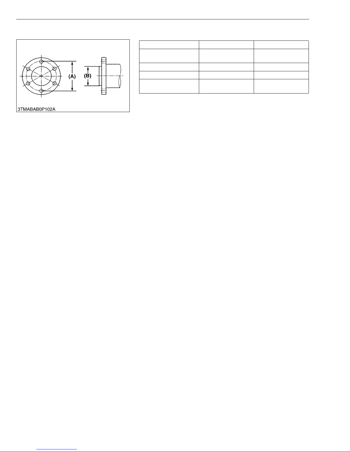
MX5100, WSM
(3) Wheel Hub
G GENERAL
Front wheel hub Rear wheel hub
Screw circle diameter (A)
Number of screws 6 8
Screws M14 × 1.5 M16 × 1.5
Hub pilot diameter (B)
152.4 mm
(6 in.)
117.4 mm
(4.625 in.)
203.2 mm
(8.0 in.)
152.4 mm
(6.0 in.)
W10433920
G-62
Page 81
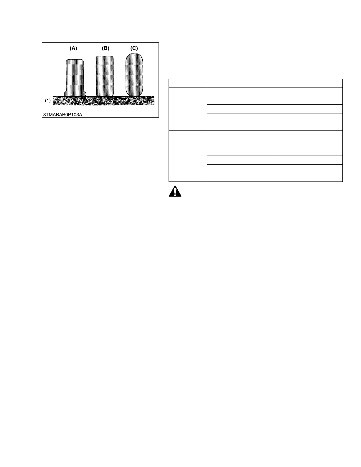
MX5100, WSM
IMPORTANT■
[3] TIRE PRESSURE
G GENERAL
• Do not use tires other than those approved by LUBOTA
■ Inflation Pressure
Though the tire pr essure is factor y-set t o the presc ribed l evel, it
naturally drops slowly in the course of time. Thus, check it everyday
and inflate as necessary.
Tire sizes Inflation Pressure
2
, 22 psi)
2
, 20 psi)
2
, 20 psi)
2
, 24 psi)
2
, 20 psi)
2
, 30 psi)
2
, 32 psi)
2
, 34 psi)
2
, 20 psi)
2
, 20 psi)
2
, 10 psi)
Rear
Front
13.6 – 28, 4 PR 150 kPa (1.5 kgf/cm
14.9 – 26, 4 PR 140 kPa (1.4 kgf/cm
17.5L – 24, 6 PR 140 kPa (1.4 kgf/cm
44 × 18 – 20, 6 PR 170 kPa (1.7 kgf/cm
610R470, 6PR 140 kPa (1.4 kgf/cm
9.5 – 16, 4 PR 205 kPa (2.1 kgf/cm
7.5L – 15, 6 PR 220 kPa (2.2 kgf/cm
9.5L – 15, 6 PR 235 kPa (2.4 kgf/cm
12 – 16.5, 6 PR 140 kPa (1.4 kgf/cm
29 × 12.50 – 15, 4 PR 140 kPa (1.4 kgf/cm
305R343, 2PR 70 kPa (0.7 kgf/cm
WARNING
• Do not attempt to mount a tire on a rim. This should be done
by a qualified person with the proper equipment.
• Always maintain the correct tire pressure.
Do not inflate tires above the recommended pressure shown
in the operator’s manual.
(1) Ground (A) Insufficient
(B) Standard
(C) Excessive
W10440050
G-63
Page 82
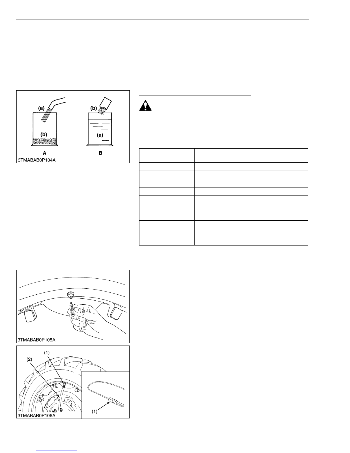
MX5100, WSM
IMPORTANT■
G GENERAL
[4] TIRE LIQUID INJECTION
Auxiliary weights can be used to increase traction force for plowing in fields or clayey ground.
Another way is to inject water or another liquid, such as a calcium chloride solution in the tires. Water must not be
used in winter si nce it freezes at 0 °C (32 °F). The calcium chloride so lution will not fr eeze and mor eover, affords
higher effect than water since its specific gravity is higher than that of water by about 20 %. Below is an explanation
of calcium chloride solution injection.
• Do not fill the front tires with liquid.
Preparation of Calcium Chloride Solution
CAUTION
• When making a calcium chloride solution, do not pour water
over calcium chloride since this results in chemical reaction
which will cause high temperature. Instead add a small
amount of calcium chloride to the water at a time until the
desired solution is achieved.
Freezing temp.
−5 °C (23 °F) 12 kg (26.4 lbs)
−10 °C (14 °F) 21 kg (46.3 lbs)
−15 °C (5 °F) 28 kg (61.7 lbs)
−20 °C (−4 °F) 34 kg (75.0 lbs)
−25 °C (−13 °F) 40 kg (88.2 lbs)
−30 °C (−22 °F) 44 kg (97.0 lbs)
−35 °C (−31 °F) 49 kg (108 lbs)
−40 °C (−40 °F) 52 kg (114.6 lbs)
−45 °C (−49 °F) 56 kg (123. 5 lbs)
−50 °C (−58 °F) 61 kg (134. 5 lbs)
Weight of CaCl
(26.5 U.S.gals, 22.0 Imp.gals) of water
2 to be dissolved in 100 L
(a) Water
(b) CaCl
2 (Calcium Chloride)
A : Bad
B : Good
W10330830
Attaching Injector
1. Lift the rear tires off the ground.
2. Turn the tire so that the air valve is at the top.
3. Remove the air valve, and attach the injector. (Code No. 07916-
52501)
(1) Injector (2) Hose
W10333310
G-64
Page 83
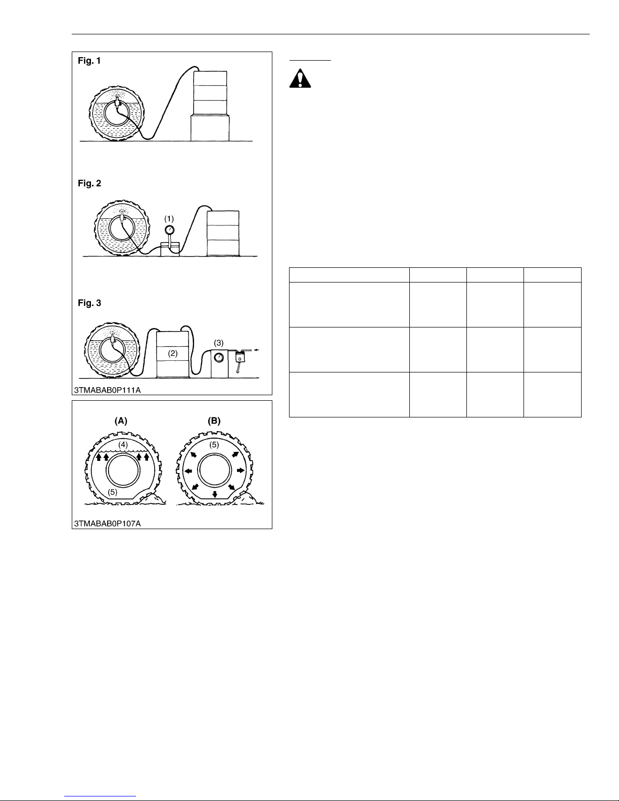
MX5100, WSM
■
G GENERAL
Injection
CAUTION
• When a calcium chloride solution is used, cool it before
pouring it into the tire.
• Do not fill tires with water or solution more than 75 % of full
capacity (to the valve stem level).
The following four ways can be used to inject water or a calcium
chloride solution into tires.
1. Gravity injection (Fig. 1)
2. Pump injection (Fig. 2)
3. Pressure tank injection (Fig. 3)
4. Injection directly from tap (only when water is being used).
NOTE
• Once injection is completed, reset the air valve, and pump
air into the tire to the specified pressure.
[Liquid weight per tire (75 % filled)]
Tire sizes 14.9 – 26 13.6 – 28 17.5L – 24
Slush free at −10 °C (14 °F)
Solid at −30 °C (−22 °F)
[Approx. 1 kg (2 lbs) CaCl
per 4 L (1 gal.) of water]
Slush free at −24 °C (−11 °F)
Solid at −47 °C (−53 °F)
[Approx. 1.5 kg (3.5 lbs)
2 per 4 L (1 gal.) of water]
CaCl
Slush free at −47 °C (−53 °F)
Solid at −52 °C (−62 °F)
[Approx. 2.25 kg (5 lbs) CaCl
per 4 L (1 gal.) of water]
(1) Pump
(2) Pressure Tank
(3) Compress o r
(4) Air
(5) Water
2
215 kg
(470 lbs)
225 kg
(495 lbs)
235 kg
2
(520 lbs)
(A) Correct : 75 %
(B) Incorrect : 100 % Full
185 kg
(410 lbs)
200 kg
(440 lbs)
215 kg
(470 lbs)
Air Compresses Like A Cushion
Water Can Not Be Compressed
235 kg
(515 lbs)
250 kg
(550 lbs)
265 kg
(585 lbs)
W10334350
G-65
Page 84
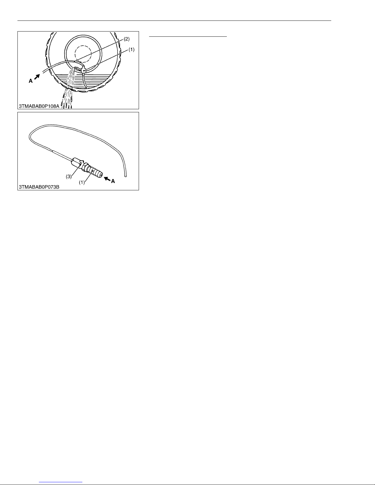
MX5100, WSM
G GENERAL
Draining Water or Solution
1. Lift the rear tires off the ground.
2. Turn the tire so that the air valve is at the bottom.
3. Remove the air valve, and drain liquid (liquid can only be drained
to the level of the valve and liquid under that level remains
inside).
4. To drain liquid completely, use the injector, and direct
compressed air into the ti re to force out the liquid throug h the
injector’s vent.
(1) Injector
(2) Hose
(3) Vent
A : Compressed Air
W10451670
G-66
Page 85
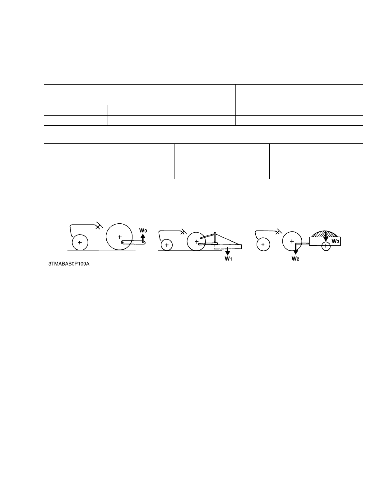
MX5100, WSM
NOTE■
G GENERAL
[5] IMPLEMENT LIMITATIONS
The KUBOTA Tractor has bee n thoroughly tested for proper performance with implemen ts sold or approved by
KUBOTA. Use with implements which exceed the maximum specifications listed below, or which are otherwise unfit
for use with the KUBOTA Tractor may result in malfuncti ons or failures of the tractor, dam age to other prope rty and
injury to the operator or others. [Any malfunctions or failures of the tractor resulting from use with improper implements
are not covered by the warranty.]
Tread (max. width)
Rear
Lower link end max. lifting weight W
2WD 4WD
1530 mm (60.2 in.) 1325 mm (52.2 in.) 1490 mm (58.7 in.) 1300 kg (2870 lbs)
Actual figures
Implement weight W
1 and / or size Max. Drawbar Load W2
As in the following list
(Shown on the next page)
Lower link end max. hydraulic lifting capacity ..... W
750 kg (1650 lbs) 3500 kg (7700 lbs)
0
Trailer loading weight W3 Max.
capacity
Implement weight................................................ The implement’s weight which can be put on the lower link : W1
Max. drawbar load .............................................. W2
Trailer loading weight .......................................... The max. loading weight for trailer (without trailer’s weight ) : W3
0Front
• Implement size may vary depending on soil operating conditions.
G-67
Page 86
MX5100, WSM
NOTE■
No. Implement Remarks MX5100
Max.Load Capacity 3500 kg (7700 lbs)
1Trailer
Max. Drawbar Load 750 kg (1650 lbs)
Max. Cutting Width 2130 mm (84 in.)
Rotary-Cutter
Max.Weight 450 kg (1000 lbs)
Max. Cutting Width 1830 mm (72 in.)
2Mower
Flail Mower
Max.Weight 500 kg (1100 lbs)
Max. Cutting Width 2130 mm (84 in.)
Sickle Bar
Max.Weight 500 kg (1100 lbs)
Rear mounted 500 L (130 U.S.gals)
3 Sprayer Max. Tank Capacity
Pull type 2000 L (529 U.S.gals)
4 Rotary Tiller Max. Tilling Width 1830 mm (72 in.)
5 Bottom Plow Max. size 16 in. × 2
Max. Harrowing Width 2130 mm (84 in.)
6 Disc-harrow (Pull type)
Max. Weight 400 kg (880 lbs)
Max. Cutting Width 1830 mm (72 in.)
7 Chisel Plow
Max. Weight 350 kg (770 lbs)
Max. Tank Capacity 300 L (80 U.S.gals)
8 Broad Caster
Max. Weight 100 kg (220 lbs)
9 Manure Spreader Max. Capacity 2000 kg (4400 lbs)
Max. Width 2450 mm (96 in.)
10 Cultivator
Number of Rows 4
Max. Weight 400 kg (880 lbs)
Max. cutting width 1830 mm (72 in.)
11 Front Blade
Max. oil pressure 17.2 MPa (175 kgf/cm
Sub frame Necessary
Max. Cutting Width 1830 mm (72 in.)
12 Rear Blade
Max. Oil Pressure 17.2 MPa (175 kgf/cm
Max. Lifting Capacity 850 kg (1870 lbs)
13 Front-end Loader
Max. Oil Pressure 17.2 MPa (175 kgf/cm
Sub frame Necessary
Max. Cutting Width 1830 mm (72 in.)
14 Bo x Blade
Max. Weight 450 kg (1000 lbs)
Max. digging depth 2290 mm (90 in.)
15 Back Hoe
Max. weight 450 kg (990 lbs)
Sub frame Necessary
Max. width 1830 mm (72 in.)
16 Snow Blade
Max. Weight 400 kg (880 lbs)
G GENERAL
2
, 2490 psi)
2
, 2490 psi)
2
, 2490 psi)
• Implement size may vary depending on soil operating conditions.
G-68
W10127360
Page 87

1 ENGINE
Page 88

Page 89

MECHANISM
NOTICE
Regarding engin e mechanism information, please ref er to Workshop Manual
DIESEL ENGINE, MECHANISM (Code No. 9Y021-01874).
Page 90

Page 91

SERVICING
CONTENTS
1. TROUBLESHOOTING....................................................................................1-S1
2. SERVICING SPECIFICATIONS ....................................................................1-S5
3. TIGHTENING TORQUES .................................... ........................................1-S13
4. CHECKING, DISASSEMBLING AND SERVICING....................................1-S15
[1] CHECKING AND ADJUSTING.............................................................1-S15
(1) Engine Body......................................................................................1-S15
(2) Lubricating System ...........................................................................1-S17
(3) Cooling System.................................................................................1-S17
(4) Fuel System......................................................................................1-S19
[2] DISASSEMBLING AND ASSEMBLING................................................1-S23
(1) Separating Engine from Tractor........................................................1-S23
(2) Engine External Components ...........................................................1-S35
(3) Cylinder Head and Valves ................................................................1-S38
(4) Piston and Connecting Rod..............................................................1-S49
(5) Flywheel and Crankshaft ..................................................................1-S52
[3] SERVICING ............................................................................................1-S55
(1) Cylinder Head and Valves ................................................................1-S55
(2) Timing Gears ....................................................................................1-S61
(3) Piston and Connecting Rod..............................................................1-S66
(4) Crankshaft.........................................................................................1-S68
(5) Cylinder.............................................................................................1-S72
(6) Oil Pump ...........................................................................................1-S73
Page 92

Page 93
MX5100, WSM
1. TROUBLESHOOTING
ENGINE
Symptom Probable Cause Solution
Engine Does Not
Start
Starter Does Not Run Battery discharged Charge G-23
No fuel Replenish fuel G-14
Air in the fuel system Vent air G-41
Water in the fuel system Change fuel and
repair or replace fuel
system
Fuel hose clogged Clean or replace G-27
Fuel filter clogged Replace G-26
Excessively high viscosity of fuel or engine oil at
low temperature
Fuel with low cetane number Use specified fuel G-8
Fuel leak due to loose injection pipe retaining nut Tighten retaining nut 1-S38
Incorrect injection timing Adjust 1-S19
Fuel camshaft worn Replace 1-S46, S47
Injection nozzle clogged Clean or replace 1-S39
Injection pump malfunc tio nin g Replace 1-S43
Seizure of crankshaft, camshaft, piston, cylinder
or bearing
Compression leak from cylinder Replace head
Improper valve timing Correct or replace
Piston ring and cylinder worn Replace 1-S51
Excessive valve clearance Adjust 1-S16
Stop solenoid malfunctioning Replace 1-S28
Starter malfunctioning Repair or replace 1-S33
Key switch malfunctioning Replace 9-S9
Wiring disconnected Connect –
Shuttle lever neutral switch malfunctioning Replace 9-S11
PTO switch malfunctioning Replace 9-S11
Use specified fuel or
engine oil
Repair or replace 1-S46, S47,
gasket, tighten
cylinder head screw,
glow plug and nozzle
holder
timing gear
Reference
Page
–
G-8
S49, S50
1-S41
1-S47
W1114419
1-S1
Page 94
MX5100, WSM
ENGINE
Symptom Probable Cause Solution
Engine Revolution Is
Not Smooth
Fuel filter clogged or dirty Replace G-32
Air cleaner clogged Clean or replace G-26
Fuel leak due to loose injection pipe retaining nut Tighten retaining nut 1-S38
Injection pump malfunctioning Replace 1-S43
Incorrect nozzle opening pressure Adjust 1-S22
Injection nozzle stuck or clogged Repair or replace 1-S22
Governor malfunctioning Repair 1-S44
Turbocharger bearing worn out Replace the
turbocharger
assembly
Turbocharger shaft bent Replace the
turbocharger
assembly
Turbocharger fin or other part damaged due to
foreign matters
Replace the
turbocharger
assembly
Either White or Blue
Exhaust Gas Is
Observed
Excessive engine oil Reduce to specified
level
Piston ring and cylinder worn or stuck Repair or replace 1-S51
Incorrect injection timing Adjust 1-S19
Oil Leak into Exhaust
Pipe or Suction Pipe
Oil pipe clogged or deformed Repair or replace 1-S37
Turbocharger’s piston ring seal faulty Replace the
turbocharger
assembly
Either Black or Dark
Gray Exhaust Gas Is
Observed
Overload Reduce the load –
Low grade fuel used Use specified fuel G-8
Fuel filter clogged Replace G-32
Air cleaner clogged Clean or replace G-26
Deficient nozzle injection Repair or replace
nozzle
Reference
Page
1-S37
1-S37
1-S37
G-8
1-S37
1-S22
W1011567
1-S2
Page 95
MX5100, WSM
ENGINE
Symptom Probable Cause Solution
Reference
Page
Deficient Output Incorrect injection timing Adjust 1-S19
Engine’s moving parts seem to be seizing Repair or replace –
Injection pump malfunc tio nin g Replace 1-S43
Deficient nozzle injection Repair or replace
1-S22
nozzle
Compression leak Check the
1-S15
compression
pressure and repair
Gas leak from exhaust system Repair or replace 1-S37
Air leak from compressor discharge side Repair or replace 1-S33
Air cleaner dirty or clogged Clean or replace G-26
Turbocharger compressor wheel turning heavily Replace the
1-S37
turbocharger
assembly
Excessive Lubricant
Oil Consumption
Piston ring’s gap facing the same direction Shift ring gap
direction
1-S50
Oil ring worn or stuck Replace 1-S51
Piston ring groove worn Replace piston 1-S50
Valve stem and valve guide worn Replace 1-S42
Crankshaft bearing, and crank pin bearing worn Replace 1-S54
Oil leaking due to defective seals or packing Replace –
Fuel Mixed into
Lubricant Oil
Injection pump’s plunger worn Repla ce 1-S43
Deficient nozzle injection Repair or replace
1-S22
nozzle
Injection pump broken Replace 1-S43
Water Mixed i nto
Lubricant Oil
Head gasket defective Replace 1-S41
Cylinder block or cylinder head flawed Replace 1-S41
W1012032
1-S3
Page 96
MX5100, WSM
ENGINE
Symptom Probable Cause Solution
Reference
Page
Low Oil Pressure Engine oil insufficient Replenish G-8
Oil strainer clogged Clean 1-S49
Relief valve stuck with di rt Clean –
Relief valve spring weaken or broken Replace –
Excessive oil clearance of crankshaft bearing Replace 1-S53
Excessive oil clearance of crankpin bearing Replace 1-S50
Excessive oil clearance of rocker arm Replace 1-S40
Oil passage clogged Clean –
Different type of oil used Use specified type of
G-8
oil
Oil pump defective Replace 1-S48
High Oil Pressure Different type of oil used Use specified type of
G-8
oil
Relief valve defective Replace –
Engine overheated Engine oil insufficient Replenish 1-S23
Fan belt broken or elongated Replace or adjust G-25
Coolant insufficient Replenish 1-S26
Radiator net and radiator fin clogged with dust Clean –
Inside of radiator corroded Clean or replace G-38
Coolant flow route corroded Clean or replace G-38
Radiator cap defective Replace 1-S26
Overload running Reduce the load –
Head gasket defective Replace 1-S41
Incorrect injection timing Adjust 1-S19
Unsuitable fuel used Use specified fuel G-8
Battery Quickly
Discharged
Battery electrolyte insufficient Replenish distilled
water and charge
Fan belt slips Adjust belt tension or
G-23
G-25
replace
Wiring disconnected Connect –
Rectifier defective Replace 9-S28
Alternator defective Replace 9-S27
Battery defective Replace G-23
W1012501
1-S4
Page 97
MX5100, WSM
ENGINE
2. SERVICING SPECIFICATIONS
ENGINE BODY
Item Factory Specification Allowable Limit
Valve Clearance (When Cold) 0.18 to 0.22 mm
0.0071 to 0.0086 in.
Compression Pressure
(When Cranking with Starting Motor)
3.24 to 3.72 MPa /
290 min
33.0 to 38.0 kgf/cm
290 min
470 to 540 psi /
290 min
-1
(rpm)
-1
(rpm)
-1
(rpm)
2
/
290 min
290 min
290 min
Top Clearance 0.575 to 0.675 mm
0.0227 to 0.0265 in.
Cylinder Head Surface Flatness – 0.05 mm / 500 mm
Valve Recessing
(Protrusion to Recessing)
Protrusion
0.05 mm
0.002 in.
–
2.55 MPa /
-1
(rpm)
26.0 kgf/cm
-1
(rpm)
370 psi /
-1
(rpm)
–
0.002 in. /
19.7 in.
–
2
/
Recessing
Valve Stem to Valve Guide
Valve Stem
Valve Guide
Clearance
O.D.
I.D.
Valve Face Angle (Intake)
Angle (Exhaust)
Valve Seat Wi dth (Intake)
Width (Exhaust)
Valve Seat Ang le (Intake)
0.15 mm
0.0059 in.
0.040 to 0.070 mm
0.0016 to 0.0027 in.
7.960 to 7.975 mm
0.3134 to 0.3139 in.
8.015 to 8.030 mm
0.3156 to 0.3161 in.
1.0 rad
60 °
0.79 rad
45 °
2.12 mm
0.0835 in.
2.12 mm
0.0835 in.
1.0 rad
60 °
0.40 mm
0.016 in.
0.10 mm
0.0039 in.
–
–
–
–
–
–
–
Valve Timing (Intake Valve) Open
Angle (Exhaust)
Close
1-S5
0.79 rad
45 °
0.35 rad (20 °)
before T.D.C.
0.79 rad (45 °)
after B.D.C.
–
–
–
W1116131
Page 98

MX5100, WSM
ENGINE BODY (Continued)
Item Factory Specification Allowable Limit
Valve Timing (Exhaust Valve) Open
0.87 rad (50 °)
before B.D.C.
ENGINE
–
Close
0 rad (0 °)
–
after T.D.C.
Valve Spring Free Length
Setting Load /
Setting Length
Tilt
41.7 to 42.2 mm
1.65 to 1.66 in.
118 N / 35.0 mm
12.0 kgf / 35.0 mm
26.5 lbf / 1.38 in.
–
41.2 mm
1.62 in.
100 N / 35.0 mm
10.2 kgf / 35.0 mm
22.5 lbf /1.38 in.
1.0 mm
0.039 in.
Rocker Arm Shaft to Rocker Arm
Rocker Arm Shaft
Oil Clearance
O.D.
0.016 to 0.045 mm
0.00063 to 0.0017 in.
13.973 to 13.984 mm
0.10 mm
0.0039 in.
–
0.55012 to 0.55055 in.
Rocker Arm
I.D.
14.000 to 14.018 mm
–
0.55119 to 0.55188 in.
Push Rod Alignment – 0.25 mm
0.0098 in.
Tappet to Tappet Guide
Oil Clearance
0.020 to 0.062 mm
0.00079 to 0.0024 in.
0.07 mm
0.003 in.
Tappet
Tappet Guide
O.D.
I.D.
23.959 to 23.980 mm
0.94327 to 0.94409 in.
24.000 to 24.021 mm
0.94489 to 0.94570 in.
–
–
W1014959
1-S6
Page 99

MX5100, WSM
ENGINE BODY (Continued)
Timing Gear
Crank Gear to Idle Gear
ENGINE
Item Factory Specification Allowable Limit
Backlash
0.04150 to 0.1122 mm
0.001634 to 0.004417
0.15 mm
0.0059 in.
in.
Idle Gear to Cam Gear
Idle Gear to Injection Pump Gear
Crank Gear to Oil Pump Gear
Idle Gear to Balancer Gear
Cam Gear to Balancer Gear
Backlash
Backlash
Backlash
Backlash
Backlash
0.04150 to 0.1154 mm
0.001634 to 0.004543
in.
0.04150 to 0.1154 mm
0.001634 to 0.004543
in.
0.04150 to 0.1090 mm
0.001634 to 0.004291
in.
0.03500 to 0.1160 mm
0.001378 to 0.004566
in.
0.03500 to 0.1160 mm
0.001378 to 0.004566
in.
0.15 mm
0.0059 in.
0.15 mm
0.0059 in.
0.15 mm
0.0059 in.
0.15 mm
0.0059 in.
0.15 mm
0.0059 in.
W1204063
1-S7
Page 100
MX5100, WSM
ENGINE BODY (Continued)
Item Factory Specification Allowable Limit
Idle Gear Side Clearance 0.12 to 0.48 mm
0.0048 to 0.018 in.
Idle Gear Shaft to Idle Gear Bushing
Oil Clearance
0.025 to 0.066 mm
0.00099 to 0.0025 in.
ENGINE
0.9 mm
0.04 in.
0.10 mm
0.0039 in.
Idle Gear Shaft
O.D.
37.959 to 37.975 mm
–
1.4945 to 1.4950 in.
Idle Gear Bushing
I.D.
38.000 to 38.025 mm
–
1.4961 to 1.4970 in.
Camshaft Side Clearance 0.070 to 0.22 mm
0.0028 to 0.0086 in.
0.30 mm
0.012 in.
Camshaft Alignment – 0.01 mm
0.0004 in.
Cam Height
(Intake)
Height
(Exhaust)
Camshaft Journal to Cylinder Block Bore
Camshaft Journal
Oil Clearance
O.D.
33.90 mm
1.335 in.
33.27 mm
1.310 in.
0.050 to 0.091 mm
0.0020 to 0.0035 in.
39.934 to 39.950 mm
33.85 mm
1.333 in.
33.22 mm
1.308 in.
0.15 mm
0.0059 in.
–
1.5722 to 1.5728 in.
Cylinder Block Bore
I.D.
40.000 to 40.025 mm
–
1.5748 to 1.5757 in.
Balancer Shaft Side Clearance 0.070 to 0.22 mm
0.0028 to 0.0086 in.
0.30 mm
0.012 in.
Balancer Shaft Alignment – 0.02 mm
0.0008 in.
W1015276
1-S8
 Loading...