

Page 1
English (Australia)
Code No. 3Y206-9971-1
M100GX·M110GX
M126GX·M135GX
MODELS
OPERATOR'S MANUAL
M
1
0
0
G
X
·
M
1
1
0
G
X
·
M
1
2
6
G
X
·
M
1
3
5
G
X
©
KUBOTA Corporation 2012
PRINTED IN JAPAN
READ AND SAVE THIS MANUAL
Page 2

KUBOTA Corporation is ···
Since its inception in 1890, KUBOTA Corporation has grown to
rank as one of the major firms in Japan.
To achieve this status, the company has through the years
diversified the range of its products and services to a remarkable
extent. Nineteen plants and 16,000 employees produce over 1,000
different items, large and small.
All these products and all the services which accompany them,
however, are unified by one central commitment. KUBOTA makes
products which, taken on a national scale, are basic necessities.
Products which are indispensable. Products which are intended to
help individuals and nations fulfill the potential inherent in their
environment. KUBOTA is the Basic Necessities Giant.
This potential includes water supply, food from the soil and from
the sea, industrial development, architecture and construction, and
transportation.
Thousands of people depend on KUBOTA's know-how, technology,
experience and customer service. You too can depend on
KUBOTA.
M100GX/M110GX/M126GX/M135GX
AQ . L . 1 - 1 . 2 . AK
Abbreviations Definitions
ABBREVIATION LIST
Two Wheel Drive
Four Wheel Drive
American Petroleum Institute
American Society of Agricultural and Biological Engineers, USA
American Society for Testing and Materials, USA
Deutsches Institut für Normung, GERMANY
Dual Traction [4WD]
Feet Per Minute
Glide Shift Transmission
High Speed-Low Speed
Hydrostatic Transmission
Meters Per Second
Power Take Off
Right-hand and left-hand sides are determined by facing
in the direction of forward travel
Roll-Over Protective Structures
Revolutions Per Minute
Revolutions Per Second
Society of Automotive Engineers, USA
Slow Moving Vehicle
2WD
4WD
API
ASABE
ASTM
DIN
DT
fpm
GST
Hi-Lo
HST
m/s
PTO
RH/LH
ROPS
rpm
r/s
SAE
SMV
Page 3

UNIVERSAL SYMBOLS
As a guide to the operation of your tractor, various universal symbols have been utilized on the instruments and
controls. The symbols are shown below with an indication of their meaning.
Safety Alert Symbol
Engine Warning
Diesel Fuel
Engine-Rotational Speed
Hourmeter/Elapsed
Operating Hours
Engine CoolantTemperature
Diesel Preheat/Glow
Plugs(Low Temperature
Start Aid)
Parking Brake
Engine Oil-Pressure
Turn Signal
Electrical Poweraccessories
Engine-Run
Engine-Start
Engine-Stop
Power Take-Off Clutch
Control-Off (Disengaged)
Position
Position Control-Raised
Position
Position Control-Lowered
Position
3-Point Lifting / Lowering
Lift Arm Height
Draft Control
Remote Cylinder-Retract
Remote Cylinder-Extend
Remote Cylinder-Float
Hazard Warning Lights
Headlight-Low Beam
Headlight-High Beam
Four-Wheel Drive-On
Fast
Slow
Creep
Windshield Wiper
Windshield Wiper
Intermittent
Side Window Defroster
Empty
Full
PTO 540 rpm
PTO 1000 rpm
Engine Intake/Combustion
Air-Filter
Battery Charging Condition
Rev-limiter Control
Constant RPM Management
Front Suspension
Regeneration
Auto Regeneration (Switch)
Regeneration (Switch)
Parked Regeneration
Engine RPM Increase
Master System Warning
Beacon Light
Power Take-Off Clutch
Control-On (Engaged)
Position
Bi-Speed turn
Differential Lock, Front
Differential Lock, Rear
Auto-Mode
Windshield Washer
Audible Warning Device
Lock
Rear Window Defroster
Steering Wheel-Tilt Control
Steering Wheel-Telescope
Control
Page 4

FOREWORD
You are now the proud owner of a KUBOTA Tractor. This tractor is a product of
KUBOTA quality engineering and manufacturing. It is made of fine materials and
under a rigid quality control system. It will give you long, satisfactory service. To
obtain the best use of your tractor, please read this manual carefully. It will help you
become familiar with the operation of the tractor and contains many helpful hints
about tractor maintenance. It is KUBOTA's policy to utilize as quickly as possible
every advance in our research. The immediate use of new techniques in the
manufacture of products may cause some small parts of this manual to be
outdated. KUBOTA distributors and dealers will have the most up-to-date
information. Please do not hesitate to consult with them.
3
This symbol, the industry's ''Safety Alert Symbol'', is used throughout this manual
and on labels on the machine itself to warn of the possibility of personal injury.
Read these instructions carefully. It is essential that you read the instructions and
safety regulations before you attempt to assemble or use this unit.
3
3
3
IMPORTANT :
NOTE :
DANGER :
WARNING :
CAUTION :
Indicates an imminently hazardous situation which, if not
avoided, will result in death or serious injury.
Indicates a potentially hazardous situation which, if not
avoided, could result in death or serious injury.
Indicates a potentially hazardous situation which, if not
avoided, may result in minor or moderate injury.
Indicates that equipment or property damage could result if
instructions are not followed.
Gives helpful information.
SAFETY FIRST
Page 5

CONTENTS
SAFE OPERATION ............................................................................................ -1
SERVICING OF TRACTOR......................................................................................... 1
SPECIFICATIONS....................................................................................................... 3
SPECIFICATION TABLE ......................................................................................... 3
TRAVELING SPEEDS ............................................................................................. 5
IMPLEMENT LIMITATIONS ........................................................................................ 6
INSTRUMENT PANEL AND CONTROLS................................................................... 8
PRE-OPERATION CHECK ....................................................................................... 13
DAILY CHECK ....................................................................................................... 13
OPERATING THE ENGINE....................................................................................... 14
EXHAUST AFTERTREATMENT DEVICES........................................................... 14
Diesel Oxidation Catalyst and Diesel Particulate Filter (DPF) Muffler............................14
Handling Points...............................................................................................................15
DPF Regeneration Process............................................................................................15
Regeneration Operating Procedure................................................................................17
PM Warning Level and Required Procedures ................................................................18
Regeneration Operating Procedure................................................................................19
PM Warning Level and Required Procedures ................................................................20
Tips on DPF Regeneration .............................................................................................21
STARTING THE ENGINE ...................................................................................... 21
COLD WEATHER STARTING ............................................................................... 26
Block Heater (if equipped) ..............................................................................................26
STOPPING THE ENGINE...................................................................................... 26
WARMING UP ....................................................................................................... 26
Warm-up and Transmission Oil at Low Temperature Range ......................................... 26
JUMP STARTING .................................................................................................. 27
OPERATING THE TRACTOR ................................................................................... 28
OPERATING NEW TRACTOR .............................................................................. 28
Do not Operate the Tractor at Full Speed for the First 50 Hours.................................... 28
Changing Lubricating Oil for New Tractors..................................................................... 28
BOARDING AND LEAVING THE TRACTOR ........................................................ 28
STARTING ............................................................................................................. 28
Operator's Seat...............................................................................................................28
Seat Belt .........................................................................................................................30
Instructional Seat............................................................................................................30
Steering Adjustment .......................................................................................................31
Extendable Mirror ...........................................................................................................31
Light Switch ....................................................................................................................31
Turn Signal / Hazard Light Switch ..................................................................................31
With Trailer Connector.................................................................................................... 32
Horn Button.....................................................................................................................32
Work Light Switch (Front) ...............................................................................................32
Work Light Switch (Rear)................................................................................................ 32
Page 6

CONTENTS
Brake Pedals (Right and Left).........................................................................................33
Clutch Pedal ...................................................................................................................34
Power Shift / Range Shift Lever (PS. Lever) ..................................................................35
DHC switch.....................................................................................................................36
Shuttle Lever...................................................................................................................37
Creep Lever (if equipped)...............................................................................................37
4WD / Bi-speed Turn Switch [4WD model]..................................................................... 38
Hand Throttle Lever........................................................................................................39
Foot Throttle ...................................................................................................................39
Rev-limiter Control Dial................................................................................................... 39
Parking Brake Lever ....................................................................................................... 39
STOPPING............................................................................................................. 39
Stopping.......................................................................................................................... 39
CHECK DURING DRIVING ................................................................................... 39
Immediately Stop the Engine if:......................................................................................39
Easy Checker(TM).......................................................................................................... 40
Fuel Gauge.....................................................................................................................41
Coolant Temperature Gauge..........................................................................................41
Tachometer.....................................................................................................................41
Hour / Trip Monitor.......................................................................................................... 41
SIDE DIGITAL DISPLAY........................................................................................ 42
Initial Setting ...................................................................................................................42
Factory-set Screen Display.............................................................................................44
ELECTRONIC ENGINE CONTROL....................................................................... 47
Rev-limiter Control Setting.............................................................................................. 47
RPM Dual Memory Setting .............................................................................................47
Constant RPM Management Control.............................................................................. 50
AUTO MODE ......................................................................................................... 51
Outline ............................................................................................................................51
Operation........................................................................................................................53
Work Speed Display .......................................................................................................54
Changing the Field Speed ..............................................................................................55
Sensitivity Adjustment.....................................................................................................56
Changing the Auto-Mode Setting....................................................................................56
FRONT SUSPENSION .......................................................................................... 59
Outline ............................................................................................................................59
Suspension Switch .........................................................................................................59
Ride Condition Damper Switch....................................................................................... 61
Manual Control Mode .....................................................................................................61
PARKING ............................................................................................................... 62
Parking............................................................................................................................ 62
OPERATING TECHNIQUES ................................................................................. 62
Differential Lock..............................................................................................................62
Rear Wheel Differential Lock Pedal................................................................................63
Front Wheel Differential Lock Switch..............................................................................63
Operating the Tractor on a Road....................................................................................64
Operating on Slopes and Rough Terrain........................................................................64
Transport the Tractor Safely...........................................................................................64
Directions for Use of Power Steering..............................................................................64
Trailer Electrical Outlet ...................................................................................................65
PTO ........................................................................................................................... 66
Page 7

CONTENTS
PTO OPERATION.................................................................................................. 66
PTO Clutch Control Switch.............................................................................................66
PTO Gear Shift Lever ..................................................................................................... 67
PTO Gear Shift Lever ..................................................................................................... 68
PTO Shaft Cover and Shaft Cap ....................................................................................68
THREE-POINT HITCH & DRAWBAR........................................................................ 69
3-POINT HITCH ..................................................................................................... 70
Selecting the holes of Lower Links ................................................................................. 70
Adjusting Lateral Float....................................................................................................70
Selecting the Top Link Mounting Holes .......................................................................... 70
Drawbar ..........................................................................................................................70
Remote Hitch UP / DOWN Switch..................................................................................71
Lifting Rod (Left) .............................................................................................................71
Lifting Rod (Right)........................................................................................................... 71
Top Link..........................................................................................................................72
Telescopic Stabilizers.....................................................................................................72
Quick Hitch (Hook type).................................................................................................. 72
DRAWBAR............................................................................................................. 74
Adjusting Drawbar Length ..............................................................................................74
Swing Drawbar ...............................................................................................................74
HYDRAULIC UNIT..................................................................................................... 75
3-POINT HITCH CONTROL SYSTEM................................................................... 75
Terminology....................................................................................................................75
Mode Selector Switch.....................................................................................................76
Position Control Mode ....................................................................................................76
Mixed Draft Control Mode............................................................................................... 77
Float Control ...................................................................................................................77
Bottom Limit Control Dial................................................................................................78
Lift Arm Top Limit Adjustment Dial .................................................................................78
3-Point Hitch Lowering Speed Adjustment Dial..............................................................78
3-Point Hitch Lowering Lock Lever.................................................................................78
3-P. Quick Raise / Lower Switch ....................................................................................79
3-Point Hitch's Position Lock ..........................................................................................80
REMOTE HYDRAULIC CONTROL SYSTEM........................................................ 80
Remote Control Valve.....................................................................................................80
Remote Control Valve Lever...........................................................................................80
Remote Control Valve Coupler Connecting and Disconnecting .....................................81
Adjusting the flow rate ....................................................................................................81
Remote Couplers Spillage Collector............................................................................... 82
Hydraulic Control Unit Use Reference Chart..................................................................83
TIRES, WHEELS AND BALLAST.............................................................................. 84
TIRES..................................................................................................................... 84
Inflation Pressure............................................................................................................84
Dual Tires ....................................................................................................................... 84
WHEEL ADJUSTMENT ......................................................................................... 85
Front Wheels (with four wheel drive) .............................................................................. 85
Adjusting Front Wheel Turning Stopper Bolt ..................................................................86
Rear Wheels...................................................................................................................87
BALLAST ............................................................................................................... 88
Front Ballast....................................................................................................................88
Page 8

CONTENTS
Rear Ballast ....................................................................................................................89
CAB OPERATION ..................................................................................................... 90
DOOR AND WINDOW........................................................................................... 90
Locking and Unlocking the Door..................................................................................... 90
Opening the Door ...........................................................................................................90
Rear Window ..................................................................................................................90
Sun Roof.........................................................................................................................91
Emergency Exit...............................................................................................................91
DOME LIGHT......................................................................................................... 91
Dome Light .....................................................................................................................91
WIPER ................................................................................................................... 91
Front Wiper / Washer Switch..........................................................................................91
Rear Wiper / Washer Switch...........................................................................................92
Using the Wipers in Cold Season...................................................................................92
AIR CONDITIONER ............................................................................................... 92
Airflow.............................................................................................................................92
Air Control Vent ..............................................................................................................93
Control Panel..................................................................................................................93
Operation........................................................................................................................94
INSTALLING THE IMPLEMENT CONTROL BOX................................................. 96
ELECTRICAL OUTLET.......................................................................................... 96
Electrical Outlet...............................................................................................................96
BEACON LIGHT .................................................................................................... 97
Beacon Light Switch .......................................................................................................97
MAINTENANCE......................................................................................................... 98
SERVICE INTERVALS .......................................................................................... 98
LUBRICANTS, FUEL AND COOLANT ................................................................ 102
PERIODIC SERVICE............................................................................................... 104
HOW TO OPEN THE HOOD ............................................................................... 104
Hood .............................................................................................................................104
Side Cover....................................................................................................................104
DAILY CHECK ..................................................................................................... 104
Walk Around Inspection................................................................................................ 105
Checking and Refueling................................................................................................105
Checking Water Separator ...........................................................................................105
Checking Engine Oil Level............................................................................................106
Checking Transmission Fluid Level..............................................................................106
Checking Coolant Level................................................................................................ 106
Cleaning Evacuator Valve ............................................................................................107
Cleaning Grill, Radiator and Screen .............................................................................107
Checking DPF Muffler...................................................................................................109
Checking Brake Pedal .................................................................................................. 109
Checking Gauges, Meter and Easy Checker(TM) ........................................................ 109
Checking Head Light, Turn Signal / Hazard Light etc................................................... 109
Checking Seat Belt .......................................................................................................109
Checking Movable Parts............................................................................................... 109
EVERY 50 HOURS .............................................................................................. 110
Checking Engine Start System.....................................................................................110
Checking Wheel Bolt Torque........................................................................................111
Checking Tie-rod Dust Cover .......................................................................................111
Page 9

CONTENTS
EVERY 100 HOURS ............................................................................................ 111
Lubricating Grease Fittings........................................................................................... 111
Cleaning Air Cleaner Primary Element ......................................................................... 113
Adjusting Fan Belt Tension........................................................................................... 114
Checking Fuel Line.......................................................................................................114
Adjusting Brake Pedal ..................................................................................................115
Adjusting Parking Brake Lever .....................................................................................115
Checking Battery Condition ..........................................................................................116
EVERY 200 HOURS ............................................................................................ 117
Checking Radiator Hose and Clamp ............................................................................117
Checking Oil Cooler Line..............................................................................................119
Checking Intake Air Line............................................................................................... 119
Checking Power Steering Line .....................................................................................119
Adjusting Toe-in............................................................................................................ 120
Draining Fuel Tank Water............................................................................................. 120
Cleaning Inner Air Filter................................................................................................121
Cleaning Fresh Air Filter...............................................................................................121
Adjusting Air-Conditioner Belt Tension.........................................................................122
EVERY 300 HOURS ............................................................................................ 122
Replacing Hydraulic Oil Filter .......................................................................................122
EVERY 400 HOURS ............................................................................................ 123
Changing Engine Oil..................................................................................................... 123
Replacing Engine Oil Filter ...........................................................................................124
Checking Fan / Air-conditioner Belt Tension ................................................................ 124
Cleaning Pre-Fuel Filter................................................................................................ 126
Replacing Fuel Filter..................................................................................................... 126
Cleaning Water Separator ............................................................................................126
Cleaning Fuel Solenoid Pump Element........................................................................127
EVERY 600 HOURS ............................................................................................ 128
Changing Transmission Fluid ....................................................................................... 128
Changing Front Differential Case Oil............................................................................129
Changing Front Axle Gear Case Oil ............................................................................. 129
Adjusting Front Axle Pivot.............................................................................................130
Adjusting King-pin Pivot................................................................................................ 130
EVERY 800 HOURS ............................................................................................ 130
Replacing Fuel Filter..................................................................................................... 130
Adjusting Engine Valve Clearance ...............................................................................130
EVERY 1500 HOURS .......................................................................................... 130
Cleaning Fuel Injector Nozzle Tip................................................................................. 130
Checking and Cleaning EGR Cooler ............................................................................ 130
Checking Accumulator.................................................................................................. 130
EVERY 3000 HOURS .......................................................................................... 130
Checking Turbocharger ................................................................................................ 130
Checking Supply Pump ................................................................................................130
Checking Intake Air Heater........................................................................................... 131
Checking and Cleaning EGR System........................................................................... 131
Cleaning DPF Muffler ...................................................................................................131
EVERY 1 YEAR ................................................................................................... 131
Replacing Air Cleaner Primary Element and Secondary Element................................ 131
Checking Air-Conditioner Pipe and Hose ..................................................................... 131
Checking CAB Isolation Cushion.................................................................................. 131
Checking Exhaust Manifold ..........................................................................................131
Page 10

CONTENTS
Checking DPF Differential Pressure Sensor Pipe ........................................................ 131
Checking EGR Pipe...................................................................................................... 131
EVERY 2 YEARS................................................................................................. 131
Flushing Cooling System and Changing Coolant .........................................................131
Anti-Freeze ...................................................................................................................132
Replacing Radiator Hose (Water pipes) ....................................................................... 133
Replacing Power Steering Hose................................................................................... 133
Replacing Fuel Hose ....................................................................................................133
Replacing Oil Cooler Line.............................................................................................133
Replacing Intake Air Line.............................................................................................. 133
Replacing DPF Differential Pressure Sensor Hose ...................................................... 133
Replacing Boost Sensor Hose...................................................................................... 133
Replacing Parking Brake Cable.................................................................................... 133
Replacing Brake Hose..................................................................................................133
Replacing Clutch Hose .................................................................................................133
Replacing Differential Lock Hose..................................................................................133
Replacing Master Cylinder Kit ......................................................................................134
Replacing Equalizer Kit.................................................................................................134
Replacing Brake Seal 1 and 2 ......................................................................................134
Replacing Lift Cylinder Hose ........................................................................................134
Replacing Air Conditioner Hose....................................................................................134
Replacing Suspension Hose.........................................................................................134
SERVICE AS REQUIRED.................................................................................... 134
Bleeding Fuel System................................................................................................... 134
Bleeding Brake System ................................................................................................135
Draining Clutch Housing Water ....................................................................................135
Replacing Fuse.............................................................................................................135
Replacing Slow-Blow Fuses ......................................................................................... 137
Replacing Light Bulb.....................................................................................................138
Replacing Head Lamp ..................................................................................................138
Lubricating Points ......................................................................................................... 138
Adding Washer Liquid...................................................................................................139
Checking the Amount of Refrigerant (gas) ...................................................................139
STORAGE ............................................................................................................... 140
TRACTOR STORAGE ......................................................................................... 140
REMOVING THE TRACTOR FROM STORAGE................................................. 140
TROUBLESHOOTING............................................................................................. 141
ENGINE TROUBLESHOOTING .......................................................................... 141
POWER SHIFT/RANGE SHIFT TROUBLE SHOOTING..................................... 143
OPTIONS................................................................................................................. 145
APPENDICES.......................................................................................................... 146
SIDE DIGITAL DISPLAY...................................................................................... 146
Changing the Information Displayed.............................................................................146
Information Displayed and its Handling ........................................................................ 147
Displaying and Using the Work History ........................................................................150
Measuring the Distance................................................................................................152
Changing the Units and Dates...................................................................................... 152
INDEX .................................................................................................................. 154
Page 11
SAFE OPERATION
-1SAFE OPERATION
Careful operation is your best insurance against an
accident.
Read and understand this manual carefully before
operating the tractor.
All operators, no matter how much experience they may
have, should read this and other related manuals before
operating the tractor or any implement attached to it. It is
the owner's obligation to instruct all operators in safe
operation.
1. BEFORE OPERATING THE TRACTOR
1. Know your equipment and its limitations. Read this
entire manual before attempting to start and operate
the tractor.
2. Pay special attention to the danger, warning and
caution labels on the tractor.
3. Do not operate tractor or any implement attached to it
while under the influence of alcohol, medication,
controlled substances or while fatigued.
4. Before allowing other people to use your tractor,
explain how to operate and have them read this
manual before operation.
5. Never wear loose, torn, or bulky clothing around
tractor. It may catch on moving parts or controls,
leading to the risk of an accident. Use additional safety
items, e.g. hard hat, safety boots or shoes, eye and
hearing protection, gloves, etc., as appropriate or
required.
6. Do not allow passengers to ride on any part of the
tractor at anytime. The operator must remain in the
tractor seat during operation.
7. Check brakes, clutch, linkage pins and other
mechanical parts for improper adjustment and wear.
Replace worn or damaged parts promptly. Check the
tightness of all nuts and bolts regularly. (For further
details, see "MAINTENANCE" section.)
8. Keep your tractor clean. Dirt, grease, and trash build
up may contribute to fires and lead to personal injury.
9. Use only implements meeting the specifications listed
under "IMPLEMENT LIMITATIONS" in this manual or
implements approved by KUBOTA.
10.Use proper weights on the front or rear of the tractor to
reduce the risk of upsets. When using the front loader,
put an implement or ballast on the 3-point hitch to
improve stability. Follow the safe operating
procedures specified in the implement or attachment
manual.
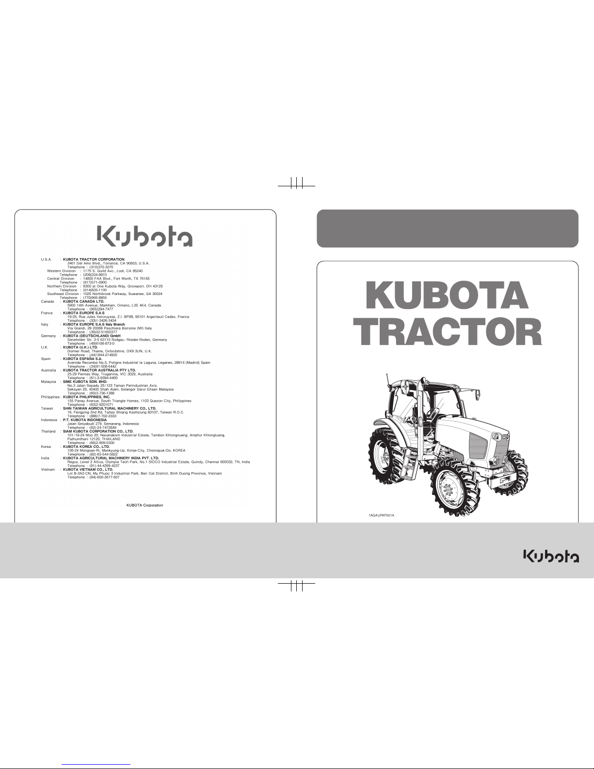
11. The narrower the tread, the greater the risk of a tractor
upset. For maximum stability, adjust the wheels to the
widest practical tread width for your application. (See
"TIRES, WHEELS AND BALLAST" section.)
(1) Rear wheels (A) Tread Width
12.Do not modify the tractor. Unauthorized modification
may affect the function of the tractor, which may result
in personal injury.
C CAB, ROPS
1. KUBOTA recommends the use of a CAB or Roll Over
Protective Structures (ROPS) and seat belt in almost
all applications. This combination will reduce the risk
of serious injury or death, should the tractor be upset.
Check for overhead clearance which may interfere
with a CAB or ROPS.
2. If the CAB or ROPS is loosened or removed for any
reason, make sure that all parts are reinstalled
correctly before operating the tractor.
3. Never modify or repair any structural member of a
CAB or ROPS because welding, bending, drilling,
grinding, or cutting may weaken the structure.
4. A damaged CAB or ROPS structure must be replaced,
not repaired or revised.
5. If any structural member of the CAB or ROPS is
damaged, replace the entire structure at your local
KUBOTA Dealer.
6. Always use the seat belt if the tractor has a CAB or
ROPS. Do not use the seat belt if there is no CAB or
ROPS. Check the seat belt regularly and replace if
frayed or damaged.
Page 12
SAFE OPERATION-2
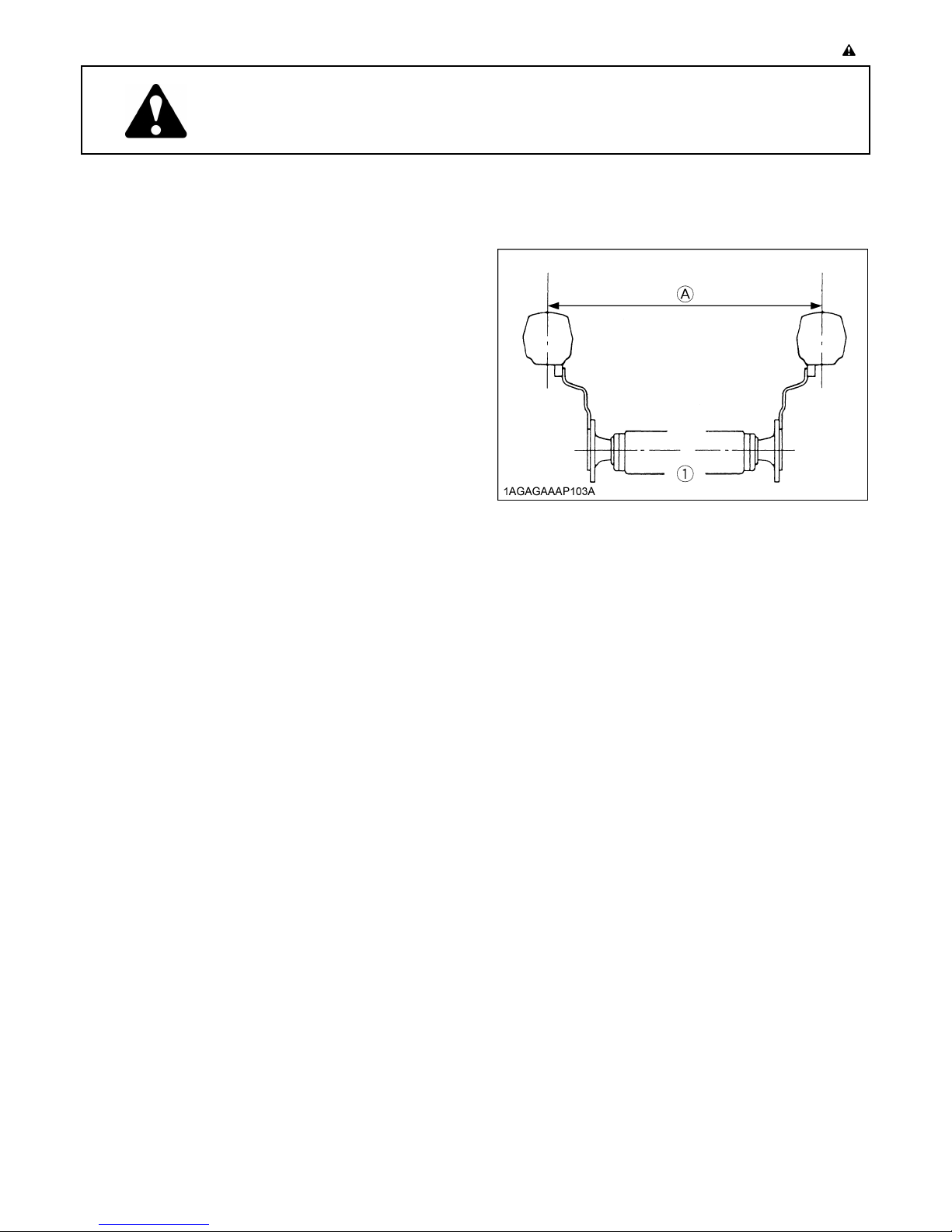
(1) CAB
(2) Seat belt
C Working
1. Pull only from the drawbar. Never hitch to axle housing
or any other point except drawbar; such arrangements
will increase the risk of serious personal injury or death
due to a tractor upset.
2. OPERATING THE TRACTOR
Operator safety is a priority. Safe operation, specifically
with respect to overturning hazards, entails understanding
the equipment and environmental conditions at the time of
use. Some prohibited uses which can affect overturning
hazards include traveling and turning with implements
and loads carried too high etc. This manual sets forth
some of the obvious risks, but the list is not, and cannot
be, exhaustive. It is the operator's responsibility to be alert
for any equipment or environmental condition that could
compromise safe operation.
C Starting
1. Always sit in the operator's seat when starting engine
or operating levers or controls. Adjust seat per
instructions in the operating the tractor section. Never
start engine while standing on the ground.
2. Before starting the engine, make sure that all levers
(including auxiliary control levers) are in their neutral
positions, that the parking brake is engaged, and that
both the clutch and the Power Take-Off (PTO) are
disengaged or "OFF".
Fasten the seat belt if the tractor has a CAB, a fixed
ROPS or a foldable ROPS in the upright and locked
position.
3. Do not start engine by shorting across starter
terminals or bypassing the safety start switch.
Machine may start in gear and move if normal starting
circuitry is bypassed.
4. Do not operate or idle engine in a non-ventilated area.
Carbon monoxide gas is colorless, odorless, and
deadly.
5. Check before each use that operator presence
controls are functioning correctly. Test safety systems.
(See "Checking Engine Start System" in "EVERY 50
HOURS" in "PERIODIC SERVICE" section.)
Do not operate unless they are functioning correctly.
(1) Drawbar
2. For trailing PTO-driven implements, set the drawbar to
the towing position.
3. Attach pulled or towed loads to the drawbar only.
4. Keep all shields and guards in place. Replace any that
are missing or damaged.
5. Avoid sudden starts. To avoid upsets, slow down
when turning, on uneven ground, and before stopping.
6. The tractor cannot turn with the rear wheel or 4-wheel
differential locked and attempting to do so could be
dangerous.
7. Do not operate near ditches, holes, embankments, or
other ground surface features which may collapse
under the tractor's weight. The risk of tractor upset is
even higher when the ground is loose or wet. Tall
grass can hide obstacles, walk the area first to be sure.
8. Watch where you are going at all times. Watch for and
avoid obstacles. Be alert at row ends, near trees, and
other obstructions.
9. When working in groups, always let the others know
what you are going to do before you do it.
10.Never try to get on or off a moving tractor.
11.Always sit in the operator's seat when operating levers
or controls.
12.Do not use "Bi-speed Turn" at high speed.
13."Bi-Speed Turn" enables short and fast turns,
therefore, become familiar with its performance before
operating in close or confined areas.
14.Do not stand between tractor and implement or trailed
vehicle unless parking brake is applied.
C Instructional seat (if equipped)
1. Instructional seat is provided only for training and
instructing operators or diagnosing machine problems.
2. It is not intended to carry children nor any other person
for any other purpose.
3. Always wear your seat belt and stabilize your body by
holding the handrail on the CAB frame.
Page 13
-3SAFE OPERATION
4. Use caution to avoid the risks of obstructing operator's
view, falling from the machine and interfering with
controls.
C Safety for children
Tragedy can occur if the operator is not alert to the
presence of children. Children generally are attracted to
machines and the work they do.
1. Never assume that children will remain where you last
saw them.
2. Keep children out of the work area and under the
watchful eye of another responsible adult.
3. Be alert and shut your machine down if children enter
the work area.
4. Never carry children on your machine. There is no safe
place for them to ride. They may fall off and be run
over or interfere with your control of the machine.
5. Never allow children to operate the machine even
under adult supervision.
6. Never allow children to play on the machine or on the
implement.
7. Use extra caution when backing up. Look behind and
down to make sure area is clear before moving.
C Operating on slopes
Slopes are a major factor related to loss-of-control and tipover accidents, which can result in severe injury or death.
All slopes require extra caution.
1. To avoid upsets, always back up steep slopes. If you
cannot back up the slope or if you feel uneasy on it, do
not operate on it. Stay off slopes too steep for safe
operation.
2. Driving forward out of a ditch, mired condition or up a
steep slope increases the risk of a tractor to be upset
backward. Always back out of these situations. Extra
caution is required with four-wheel drive models
because their increased traction can give the operator
false confidence in the tractor's ability to climb slopes.
3. Keep all movement on slopes slow and gradual. Do
not make sudden changes in speed, direction or apply
brake and make sudden motions of the steering
wheel.
4. Avoid disengaging the clutch or changing gears speed
when climbing or going down a slope. If on a slope
disengaging the clutch or changing gears to neutral
could cause loss of control.
5. Special attention should be made to the weight and
location of implements and loads as such will affect the
stability of the tractor.
6. To improve stability on slope, set widest wheel tread
as shown in "TIRES, WHEELS AND BALLAST"
section.
Follow recommendations for proper ballasting.
7. To avoid free wheeling:
A Do not shift the shuttle lever while on a slope.
A Stop completely by using the brake and by
depressing the clutch pedal, then shift the shuttle
lever.
A Start off after selecting shuttle direction, by
releasing the clutch pedal.
C Driving the tractor on the road
1. Lock the two brake pedals together to help assure
straight-line stops. Uneven braking at road speeds
could cause the tractor to tip over.
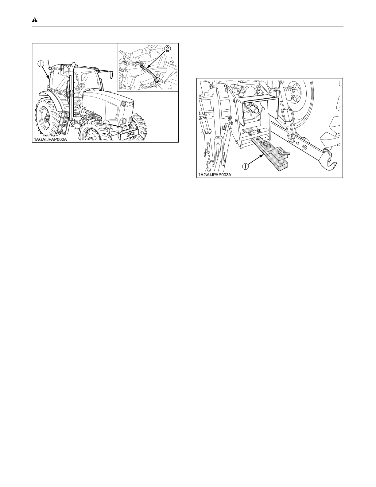
(1) Brake Pedal (LH)
(2) Brake Pedal (RH)
(3) Brake Pedal Lock
(A) Whenever travelling on the road
2. Check the front wheel engagement. The braking
characteristics are different between two and four
wheel drive. Be aware of the difference and use
carefully.
3. Always slow the tractor down before turning. Turning
at high speed may tip the tractor over.
4. Observe all local traffic and safety regulations.
Use the registration plate as required.
(1) Registration plate
5. Turn the headlights on. Dim them when meeting
another vehicle.
6. Drive at speeds that allow you to maintain control at all
times.
7. Do not apply the differential lock while traveling at road
speeds. The tractor may run out of control.
Page 14
SAFE OPERATION-4
8. Avoid sudden motions of the steering wheel as they
can lead to a dangerous loss of stability. The risk is
especially great when the tractor is traveling at road
speeds.
9. Do not operate an implement while the tractor is on the
road. Lock the 3-point hitch in the raised position.
10.Set the implement lowering control in the "LOCK"
position to hold the implement in the raised position.
(1) 3-point hitch lowering lock lever (A) "LOCK"
(B) "UNLOCK"
3. PARKING THE TRACTOR
1. Disengage the PTO, lower all implements to the
ground, place all control levers in their neutral
positions, set the parking brake, stop the engine,
remove the key from the ignition and lock the cab door
(if equipped). Leaving transmission in gear with the
engine stopped will not prevent tractor from rolling.
2. Make sure that the tractor has come to a complete
stop before dismounting.
3. Avoid parking on steep slopes, if at all possible park on
a firm and level surface; if not, park across a slope with
chock the wheels.
Failure to comply with this warning may allow the
tractor to move and could cause injury or death.
2. Keep the PTO shaft cover in place at all times.
Replace the PTO shaft cap when the shaft is not in
use.
(1) PTO Shaft cover
(2) PTO Shaft cap
(A) "NORMAL POSITION"
(B) "RAISED POSITION"
3. Before installing or using PTO driven equipment, read
the manufacturer's manual and review the safety
labels attached to the equipment.
To prevent PTO driven equipment from improper or
unsafe use, select the lower speed (540rpm) unless
the higher one is specifically recommended as safe by
the equipment manufacture.
4. When operating stationary PTO driven equipment,
always apply the tractor parking brake and place
chocks behind and in front of the rear wheels. Stay
clear of all rotating parts. Never step over rotating
parts.
5. USING 3-POINT HITCH
1. Use the 3-point hitch only with equipment designed for
3-point hitch usage.
2. When using a 3-point hitch mounted implement, be
sure to install the proper counterbalance weight on the
front of the tractor.
4. OPERATING THE PTO
1. Wait until all moving components have completely
stopped before getting off the tractor, connecting,
disconnecting, adjusting, cleaning, or servicing any
PTO driven equipment.
Page 15
-5SAFE OPERATION
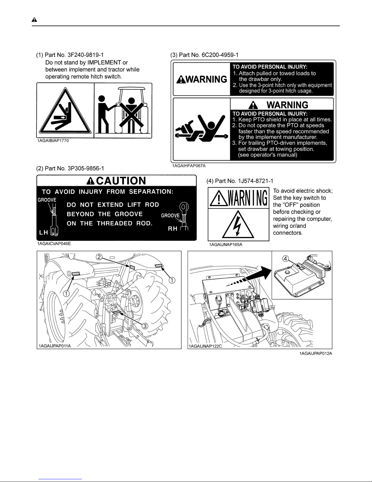
3. To avoid injury from separation:
Do not extend lift rod beyond the groove on the
threaded rod.
(1) Groove
4. Use [UP-DOWN] switch or lever only on farm fields.
For all other application, use hydraulic lever to move
attachment.
6. SERVICING THE TRACTOR
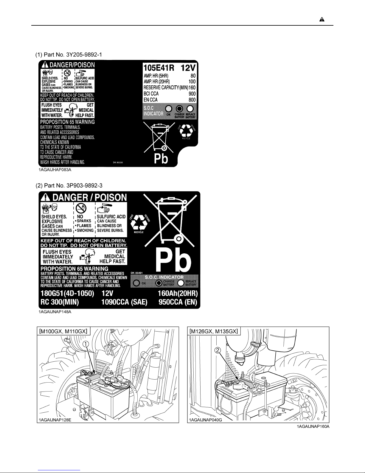
8. To avoid the possibility of battery explosion, do not use
or charge the refillable type battery if the fluid level is
below the LOWER ( lower limit level ) mark. Check the
fluid level regularly and add distilled water as required
so that the fluid level is between the UPPER and
LOWER levels.
9. To avoid sparks from an accidental short circuit,
always disconnect the battery's ground cable (-) first
and reconnect it last.
(1) Battery
Before servicing the tractor, park it on a firm, flat and level
surface, set the parking brake, lower all implements to the
ground, place the gear shift lever in neutral, stop the
engine and remove the key.
1. Allow the tractor time to cool off before working on or
near the engine, muffler, radiator, etc.
2. Do not remove radiator cap while coolant is hot. When
cool, slowly rotate cap to the first stop and allow
sufficient time for excess pressure to escape before
removing the cap completely. If the tractor has a
coolant recovery tank, add coolant or water to the tank,
not the radiator. (See "Checking Coolant Level" in
"DAILY CHECK" in "PERIODIC SERVICE" section.)
3. Always stop the engine before refueling. Avoid spills
and overfilling.
4. Do not smoke when working around battery or when
refueling. Keep all sparks and flames away from
battery and fuel tank. The battery presents an
explosive hazard, because it gives off hydrogen and
oxygen especially when recharging.
5. Before "jump starting" a dead battery, read and follow
all of the instructions. (See "JUMP STARTING" in
"OPERATING THE ENGINE" section.)
6. Keep first aid kit and fire extinguisher handy at all
times.
7. Disconnect the battery's ground cable before working
on or near electric components.
(1) Battery
10.Do not attempt to mount a tire on a rim. This should be
done by a qualified person with the proper equipment.
Page 16
SAFE OPERATION-6
11.Always maintain the correct tire pressure. Do not
inflate tires above the recommended pressure shown
in the operator's manual.
12.Securely support the tractor when either changing
wheels or adjusting the wheel tread width.
13.Make sure that wheel bolts have been tightened to the
specified torque.
14.Disconnect the battery's ground cable and stop the
engine to avoid the possibility of the machine runaway
due to 4WD braking system during testing, service or
repair with only rear wheels off the ground.
15.Do not work under any hydraulically supported
devices. They can settle, suddenly leak down, or be
accidentally lowered. If it is necessary to work under
tractor or any machine elements for servicing or
adjustment, securely support them with stands or
suitable blocking beforehand.
16.Escaping hydraulic fluid under pressure has sufficient
force to penetrate skin, causing serious personal
injury. Before disconnecting hydraulic lines, be sure to
release all residual pressure. Before applying
pressure to the hydraulic system, make sure that all
connections are tight and that all lines, pipes, and
hoses are free of damage.
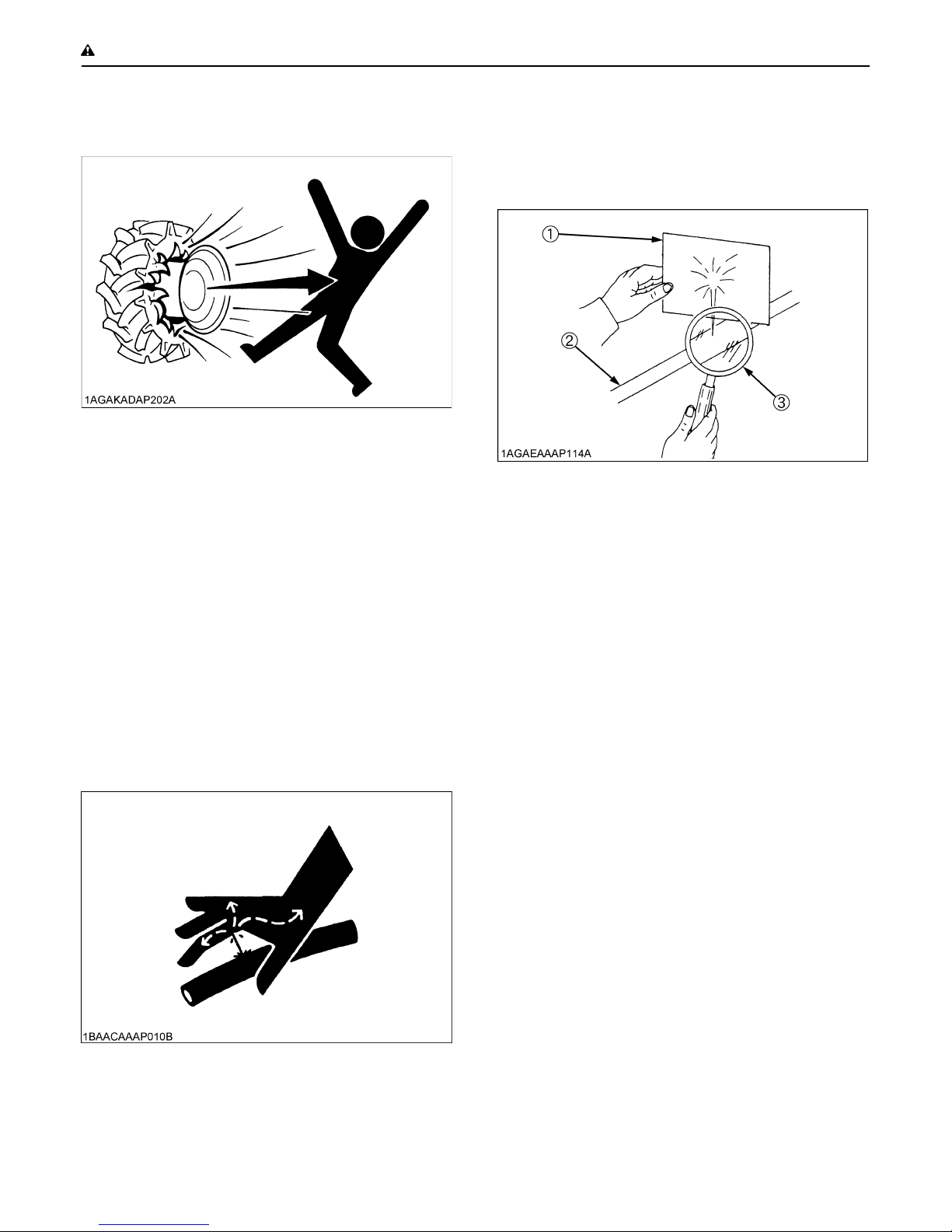
17.Fluid escaping from pinholes may be invisible. Do not
use hands to search for suspected leaks; use a piece
of cardboard or wood. Use of safety goggles or other
eye protection is also highly recommended. If injured
by escaping fluid, see a medical doctor at once. This
fluid will produce gangrene or severe allergic reaction.
(1) Cardboard
(2) Hydraulic line
(3) Magnifying glass
18.Do not open high-pressure fuel system.
High-pressure fluid remaining in fuel lines can cause
serious injury. Do not disconnect nor attempt to repair
fuel lines, sensors, or any other components between
the high-pressure fuel pump and injectors on engines
with high pressure common rail fuel system.
19.To avoid hazardous high voltage, turn the key switch
to the OFF position if it is necessary to check to repair
the computer, harness or connectors.
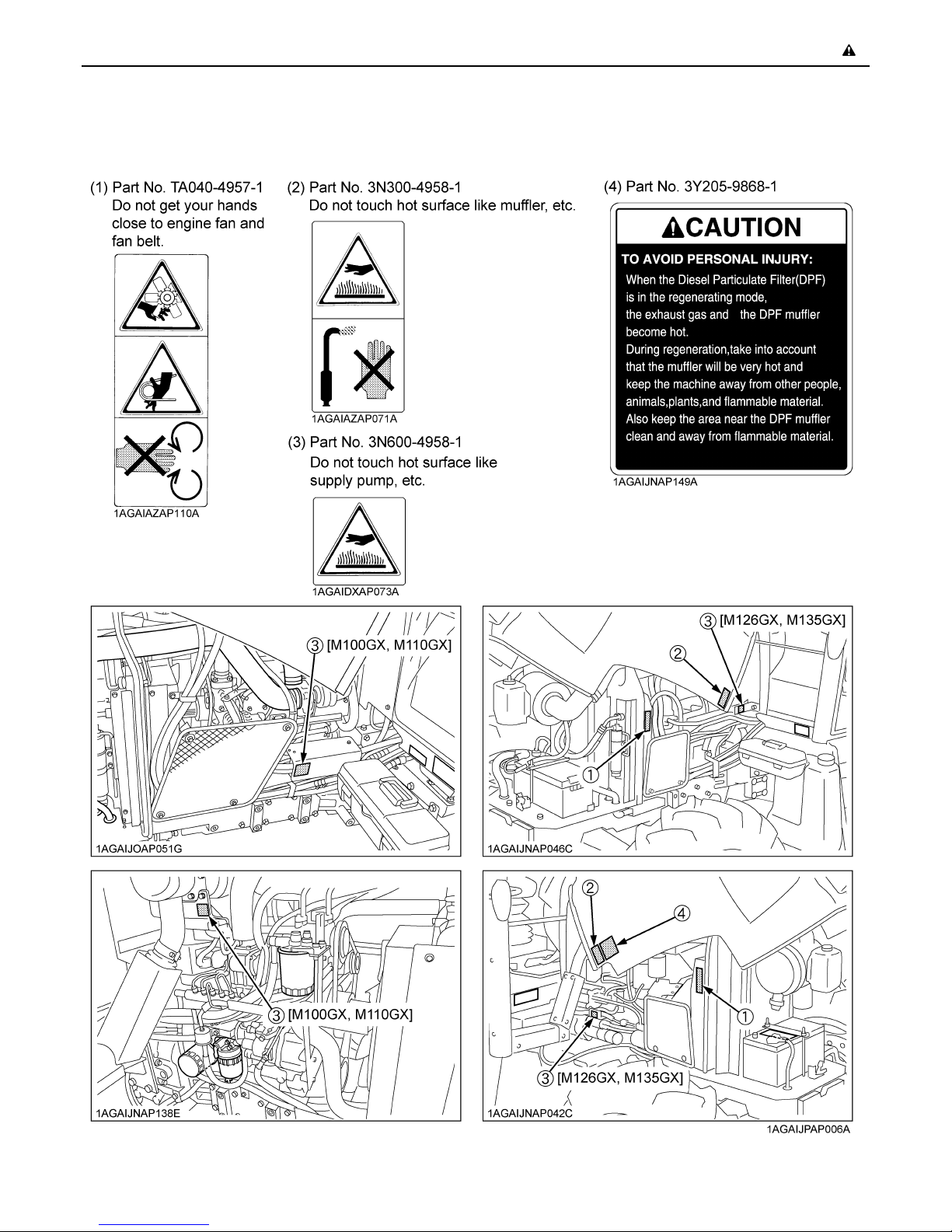
20.During Diesel Particulate Filter (hereinafter called
DPF) regenerating operations, exhaust gases and
exhaust filter components reach temperatures hot
enough to burn people, or ignite or melt common
materials.
21.Keep tractor away from people, animals or structures
which may be susceptible to harm or damage from hot
exhaust gases.
22.To prevent fires, keep the DPF muffler and its
surroundings clear of anything flammable and keep
clean at all times.
23.During regeneration, white exhaust gas may be
visible. Do not allow regeneration in a non-ventilated
space.
24.During regeneration, do not leave the tractor.
25.Before servicing a tractor equipped with the front
suspension, be sure to lower the machine to the lowest
position.
26.The front suspension hydraulic circuit is still under high
pressure after the engine has stopped. Do not
disconnect the pipes and/or hoses because you may
get injured by high-pressure oil. If pipes and/or hoses
are found worn or damaged, consult your local
KUBOTA Dealer for this service.
Page 17
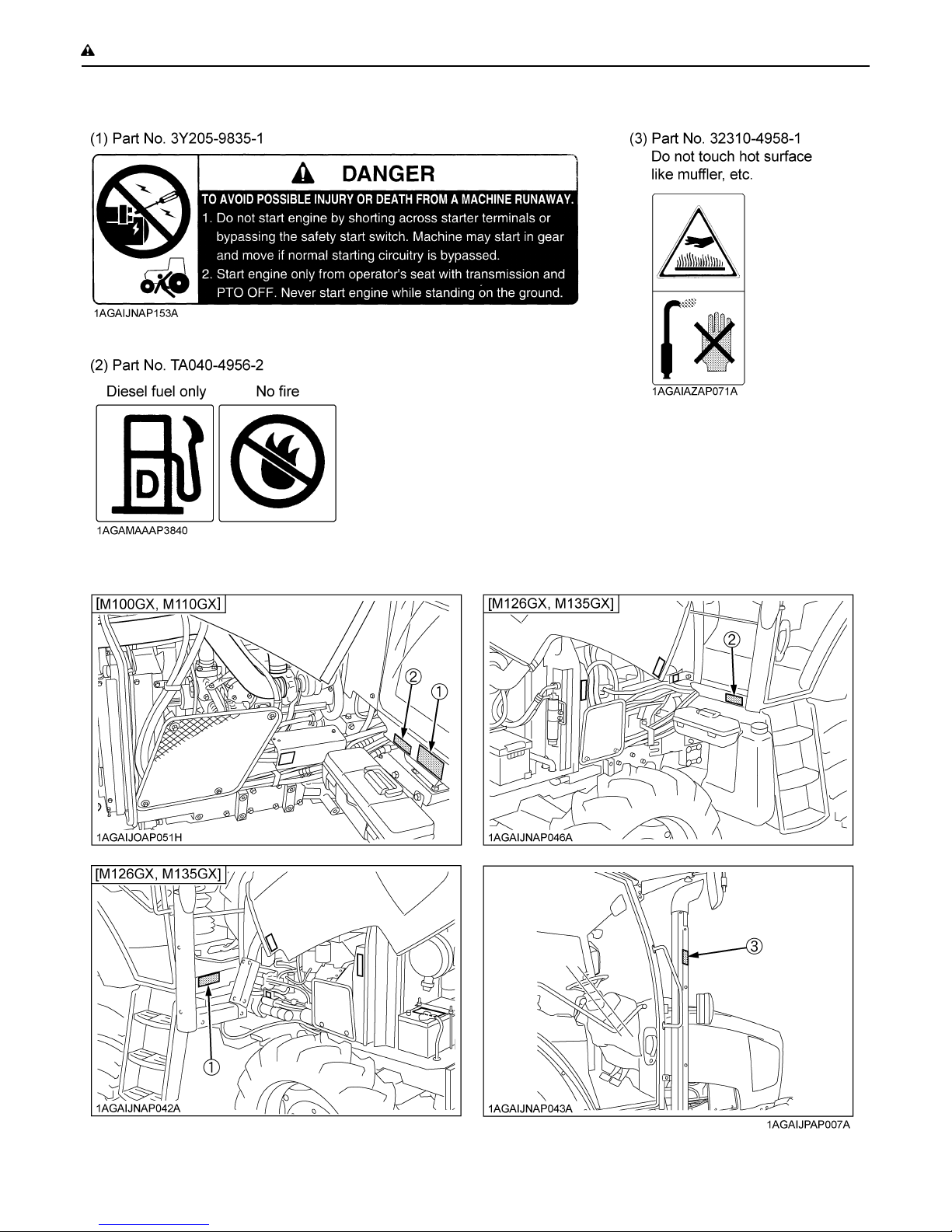
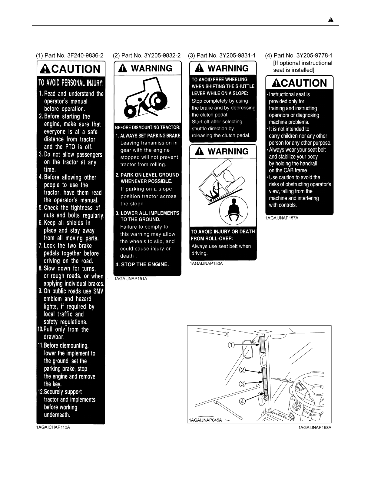
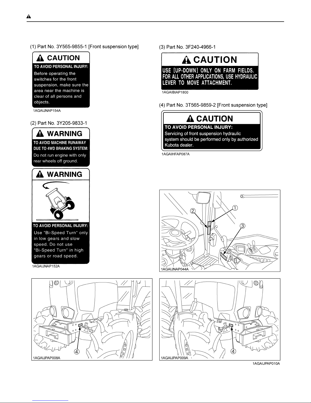
7. DANGER, WARNING AND CAUTION LABELS
-7SAFE OPERATION
Page 18
SAFE OPERATION-8
Page 19
-9SAFE OPERATION
Page 20
SAFE OPERATION-10
Page 21
-11SAFE OPERATION
Page 22
SAFE OPERATION-12
8. CARE OF DANGER, WARNING AND CAUTION LABELS
1. Keep danger, warning and caution labels clean and free from obstructing material.
2. Clean danger, warning and caution labels with soap and water, dry with a soft cloth.
3. Replace damaged or missing danger, warning and caution labels with new labels from your local KUBOTA Dealer.
4. If a component with danger, warning and caution label(s) affixed is replaced with new part, make sure new label(s) is
(are) attached in the same location(s) as the replaced component.
5. Mount new danger, warning and caution labels by applying on a clean dry surface and pressing any bubbles to outside
edge.
Page 23
SERVICING OF TRACTOR
Your dealer is interested in your new tractor and has the
desire to help you get the most value from it. After reading
this manual thoroughly, you will find that you can do some
of the regular maintenance yourself.
However, when in need of parts or major service, be sure
to see your KUBOTA Dealer.
For service, contact the KUBOTA Dealership from which
you purchased your tractor or your local KUBOTA Dealer.
When in need of parts, be prepared to give your dealer the
tractor, CAB/ROPS and engine serial numbers.
Locate the serial numbers now and record them in the
space provided.
Type Serial No.
1SERVICING OF TRACTOR
Tractor
CAB / ROPS
Engine
Date of Purchase
Name of Dealer
(To be filled in by purchaser)
C Warranty
This tractor is warranted under the KUBOTA Limited
Express Warranty, a copy of which may be obtained from
your selling dealer. No warranty shall, however, apply if
the tractor has not been handled according to the
instruction given in the Operator's Manual even it is within
the warranty period.
C Scrapping the tractor and its procedure
To put the tractor out of service, correctly follow the local
rules and regulations of the country or territory where you
scrap it. If you have questions, consult your local
KUBOTA Dealer.
(1) Tractor identification plate
(2) Tractor serial number
(1) Engine serial number
(1) Engine serial number
Page 24
SERVICING OF TRACTOR2
(1) CAB identification plate (CAB Serial No.)
(1) Diesel particulate Filter (DPF) serial number
Page 25

SPECIFICATIONS
SPECIFICATION TABLE
3SPECIFICATIONS
Engine
Model
Model V3800-TI-CRS V6108-TI-CRS
Type
Number of cylinders 4
Total displacement cm 3769 6124
Bore and stroke mm 100 x 120 118 x 140
Rated revolution rpm 2600 2200
Low idling revolution rpm 800 to 850
Net power *1 kW (HP) 74.6 (100) 81.7 (109.5) 93.2 (125) 100.7 (135)
PTO power *1
(factory observed)
Battery capacity
Fuel tank capacity L 190
Engine oil capacity L 10.5 14.6
Coolant capacity L 9.6 14.6
kW (HP) /
rpm
M100GX M110GX M126GX M135GX
4WD
Common rail system, Direct Injection, with turbocharger,
water-cooled 4 cycle diesel
64.1 (86) /
2600
12V, 100Ah at 20hours,
900CCA
71.6 (96) /
2600
80.6 (108) /
2200
12V, 160Ah at 20hours,
1090CCA
88.0 (118) /
2200
Overall length mm 4245 4400 4400 <4390>
Overall width
(minimum tread)
Overall height mm 2810 2885
Dimensions
Weight kg 4100 4640 4640 <4840>
Traveling
system
Wheel base mm 2435 2690 2690 <2680>
Tread
Crop clearance mm 560 590 615
Standard
tire size
Clutch Multiple wet disc, Electronic Hydraulically operated
Steering Hydrostatic Power Steering
Braking system Hydraulically operated wet disk
Differential Bevel gears with differential lock (Front, Rear)
Front mm 1430/1530 1555/1655 1620 to 1740
Rear mm 1530 to 2035 1590 to 2085
Front tires 340/85R24 420/70R24
Rear tires 480/70R34 520/70R38
mm 2100 2130
Page 26

4 SPECIFICATIONS
Hydraulic
unit
PTO
Model
Hydraulic control system Electronic draft control
Pump capacity L/min 70.9 77.2
Three point hitch Category 2
At lifting
Max.
lifting
force
Remote hydraulic control 2 standard (3rd & 4th valve optional)
System pressure
Traction system Swinging drawbar, adjustable in direction
Live PTO
(Independent)
points
24 in.
behind
lifting
point *2
Direction of turning Clockwise, viewed from tractor rear
PTO/
Engine
speed
kg
kg 4300 4900
MPa
(kgf/cm )
rpm
M100GX M110GX M126GX M135GX
4WD
5000 At lower link end with links
horizontal
6 splines:
540 / 2405
1000 / 2529
6100 At lower link end with links
horizontal
19.6 (200)
6 splines:
540 / 1994
1000 / 2050
The company reserves the right to change the specifications without notice.
NOTE: *1 Manufacturer's estimate
*2 Top link mounting: upper hole
< >: Front suspension type
Page 27

TRAVELING SPEEDS
Model M100GX, M110GX M126GX, M135GX
Tire size (Rear) 480/70R34 520/70R38
Range Speed (km/h) Speed (km/h)
1 0.19 0.20
2 0.23 0.24
3 0.28 0.29
C
L
M
H
4 0.36 0.36
5 0.40 0.41
6 0.49 0.50
7 0.59 0.61
8 0.74 0.74
1 0.80 0.84
2 0.98 1.02
3 1.20 1.24
4 1.50 1.51
5 1.67 1.74
6 2.05 2.12
7 2.49 2.57
8 3.13 3.13
1 3.40 3.55
2 4.17 4.31
3 5.08 5.24
4 6.37 6.38
5 7.08 7.39
6 8.67 8.97
7 10.57 10.89
8 13.26 13.28
1 9.4 9.8
2 11.5 11.9
3 14.0 14.5
4 17.6 17.6
5 19.6 20.4
6 23.9 24.8
7 29.2 30.1
8 * 36.6 36.7
5SPECIFICATIONS
(At rated engine rpm)
The company reserves the right to change the specifications without notice.
* At maximum engine rpm.
Page 28
6 IMPLEMENT LIMITATIONS
IMPLEMENT LIMITATIONS
The KUBOTA Tractor has been thoroughly tested for proper performance with implements sold or approved by KUBOTA.
Use with implements which are not sold or approved by KUBOTA and which exceed the maximum specifications listed
below, or which are otherwise unfit for use with the KUBOTA Tractor may result in malfunctions or failures of the tractor,
damage to other property and injury to the operator or others. [Any malfunctions or failures of the tractor resulting from use
with improper implements are not covered by the warranty.]
Tread (max. width)
Front Rear
M100GX 1530 mm
M110GX 1655 mm
M126GX
M135GX
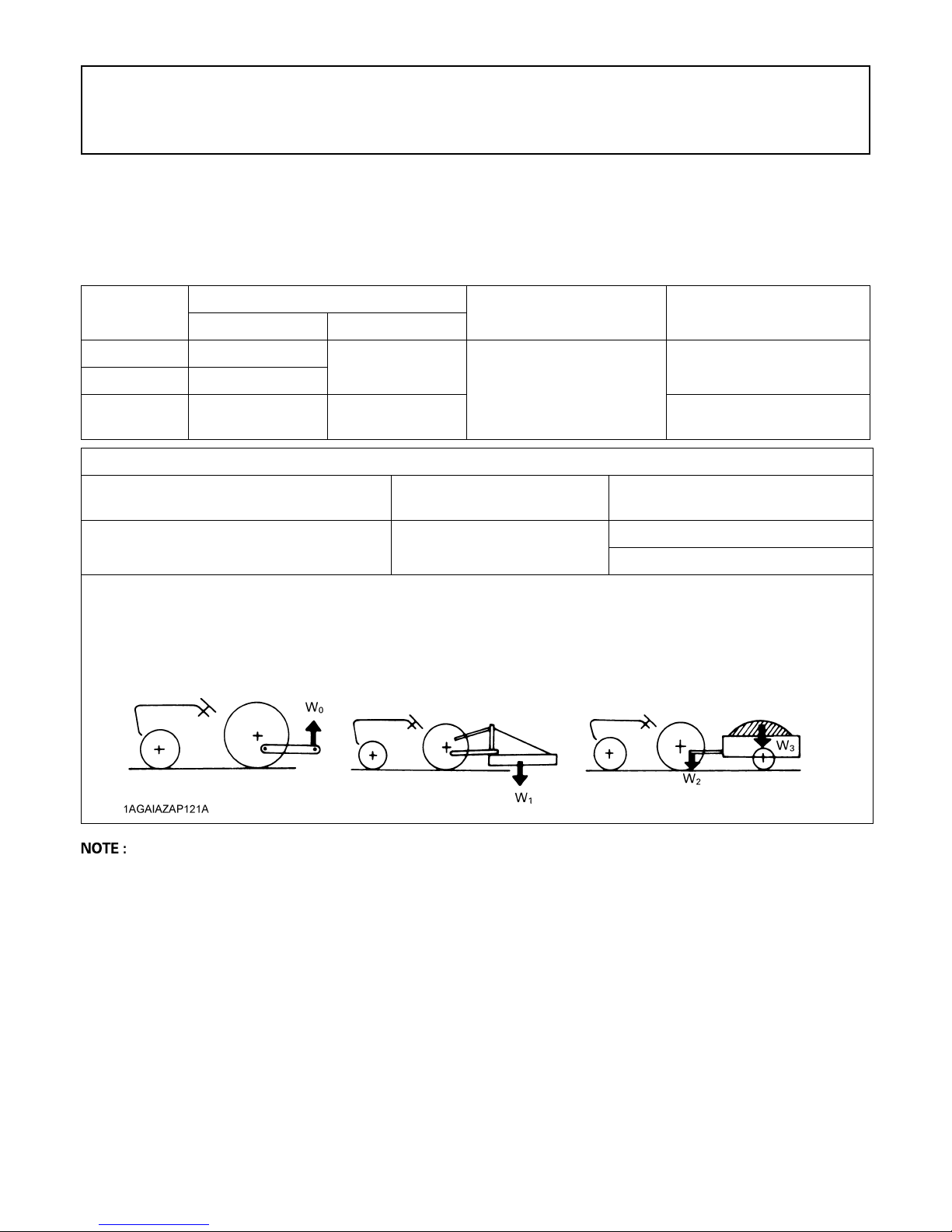
Implement weight W 1
As in the following list
(Shown on the next page)
Lower link end max,
hydraulic lifting capacity................. W 0
Implement weight...........................The implement's weight which can be put on the lower link: W 1
Max. drawbar load..........................W 2
Trailer loading weight......................The max. loading weight for trailer (without trailer's weight): W 3
1740 mm 2085 mm 6100 kg
and / or size
2035 mm
Actual figures
Max. Drawbar Load W 2
1500 kg (3300 lbs.)
Operating condition
IMPORTANT
A Tractor with front spacer
option is not approved for
use with front loader.
Lower link end max. lifting
Trailer loading weight W 3
Max. capacity
7000 kg (15400 lbs.)
8000 kg (17600 lbs.)
capacity W 0
5000 kg
A Implement size may vary depending on soil operating conditions.
A Strictly follow the instructions outlined in the operator’s manual of the mounted or trailed machinery or trailer, and do
not operate the combination tractor - machine or tractor - trailer unless all instructions have been followed
A Forestry Application
Following hazards exist;
(a) toppling trees, primarily in case a rear-mounted tree grab-crane is mounted at the rear of the tractor;
(b) penetrating objects in the operator’s enclosure, primarily in case a winch is mounted at the rear of the tractor.
Optional equipments such as OPS (Operator Protective Structure), FOPS (Falling Object Protective Structure), etc. to
deal with these hazards and other related hazards are not available for this tractor. Without such optional equipment
use is limited to tractor specific applications like transport and stationary work.
Page 29

7IMPLEMENT LIMITATIONS
No. Implement Remarks
1Slurry Tank
2 Trailer
Rotary-Cutter
3Mower
4 Sprayer
5 Rotary Tiller
6 Bottom Plow
Disk
7
harrow
8Disc Plow
9 Sub Soiler
10 Cultivator
11 Front Blade *1,*2
12 Rear Blade
13 Front Loader *1,*2
14 Box Blade
15 Back Hoe *2
16 Snow Blade
Flail Mower
(Heavy)
S i c k l e B a r M a x . C u t t i n g W i d t h m m 3 0 5 0 3 0 5 0
3P Type
Drawbar Type Max. Harrowing Width mm 4570 4570
Max. Tank Capacity L 5000 6000
Max. Load Capacity kg 6000 7000
Max. Load Capacity kg 7000 8000
Max. Drawbar Load kg 1500 1500
Max. Cutting Width mm 3200 3200
Max. Weight kg 800 800
M a x . C u t t i n g W i d t h m m 4 2 6 7 4 2 6 7
Max. Weight kg 1360 1360
Mid L 1000 1200
Max. TankCapacity
Max. Tilling Width mm 2700 2700
Max. Weight kg 1200 1200
Max. Size
Max. Weight kg 3P Type 1100 1100
Max. Size 24 in. x 30 24 in. x 30
M a x . H a r r o w i n g W i d t h m m 3 6 0 0 3 6 0 0
Max. Weight kg 1000 1000
Max. Size 30 in. x 4 30 in. x 4
Max. Weight kg 1000 1000
Numbers of Cultivating Tines 3 3
Cultivating Depth mm 600 600
Max. Width mm 5490 5490
Number of Rows 6 6
Max. Weight kg 1000 1000
Max. Cutting Width mm 2600 2600
Max. Oil Pressure MPa 18.1 18.1
Max. Cutting Width mm 2600 2600
Max. Oil Pressure MPa 18.1 18.1
Max. Lifting Capacity (Bucket
pivot pin, max. height) *3
Max. Oil Pressure MPa 20.5 20.5
Max. Cutting Width mm 2430 2430
Max. Weight kg 800 800
Max. Digging Depth mm 3050 3050
Max. Weight kg 1200 1200
Max. Width mm 2600 2600
Max. Weight kg 800 800
Rear 3P L 1200 1400
Drawbar L 5500 6000
M100GX, M110GX M126GX, M135GX
4WD 4WD
14 in. x 5
18 in. x 4
20 in. x 3
kg 1950 2210
22 in. x 2
24 in. x 1
14 in. x 6
18 in. x 5
20 in. x 4
22 in. x 2
24 in. x 1
A Implement size may vary depending on soil operating conditions.
*1 Must remove front weight with this implement.
*2 Need subframe.
*3 The value contains the weight of KUBOTA standard bucket.
Page 30
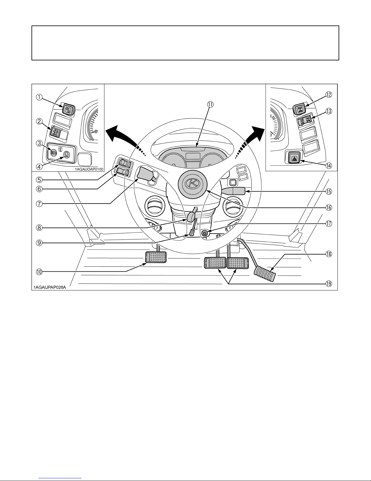
8 INSTRUMENT PANEL AND CONTROLS
INSTRUMENT PANEL AND CONTROLS
B Instrument Panel, Switches and Hand Controls
ILLUSTRATED CONTENTS ILLUSTRATED CONTENTS
(1) Parked regeneration switch ................................... 14 (11) Instrument panel .................................................. 39
(2) Auto regeneration switch ....................................... 14 (12) Front wheel differential lock switch ....................... 63
(3) Display switch (Hour, Trip) ..................................... 41 (13) 4WD / Bi-speed turn switch .................................. 38
(4) Engine RPM dual memory A/B indicator switch ..... 47 (14) Hazard light switch ............................................... 31
(5) Front wiper / washer switch .................................... 91 (15) Turn signal / Head light switch .............................. 31, 31
(6) Rear wiper / washer switch .................................... 92 (16) Horn button .......................................................... 32
(7) Shuttle lever ........................................................... 37 (17) Key switch ........................................................... ---
(8) Steering wheel telescope lever .............................. 31 (18) Foot throttle ......................................................... 39
(9) Steering wheel tilt lever ........................................ 31 (19) Brake pedal ......................................................... 33
(10) Clutch pedal ......................................................... 34
Page 31

9INSTRUMENT PANEL AND CONTROLS
ILLUSTRATED CONTENTS ILLUSTRATED CONTENTS
(1) Liquid crystal display ........................................ next page (15) Regeneration indicator ....................................... 14
(2) Turn signal / Hazard indicator ............................... 31 (16) Parked regeneration indicator ............................ 14
(3) High-beam indicator ............................................. 31 (17) Engine RPM increase indicator .......................... 14
(4) Master system warning indicator .......................... 40 (18) Constant RPM management indicator ................ 50
(5) Trailer indicator .................................................... 32 (19) 3-P. Lifting / Lowering indicator .......................... 79
(6) Fuel level indicator ............................................... 40 (20) Draft indicator ..................................................... 76
(7) Electrical charge warning indicator ....................... 40 (21) PTO clutch indicator ........................................... 66
(8) Engine warning indicator ...................................... 40 (22) Engine oil pressure warning indicator ................. 40
(9) Tachometer .......................................................... 41 (23) Air cleaner indicator ............................................ 40
(10) Fuel gauge ......................................................... 41 (24) Parking brake warning indicator ......................... 40
(11) Coolant temperature gauge ................................ 41 (25) Heater indicator .................................................. 26
(12) 4WD indicator..................................................... 38
(13) Bi-speed turn indicator ....................................... 38
(14) Rear wheel differential lock indicator .................. 63
(26) Front suspension indicator
[Front suspension type, Side digital display] ....... 59
Page 32

10 INSTRUMENT PANEL AND CONTROLS
C Liquid Crystal Display
Refer-
No. Message Description
Displays "F", "R" or "N". "F" is displayed when forward operation is selected with the shuttle lever.
(1)
(2)
Displays "1" - "8" or "E". Displays the number of the Power shift ratios that was selected with the Up-shift/Down-
(3)
Displays "L", "M", "H", "C",
(4)
or "N".
(5)
(6)
(6) Lights up when the RPM dual memory has been set. 47
(7)
(8) TRIP Lights up when trip time mode is selected. 41
Displays "h", "A", "B", or
(9)
"L".
(10) Displays "0" - "99". Digital display of the lift arm height. ---
"R" is displayed when reverse operation is selected.
("N" is displayed when the lever is in the neutral position.)
AUTO MODE (Automatic speed change)
Lights up when Travel mode or Field mode is selected.
Turns off when Travel mode and Field mode are not selected.
shift button. "E" appears in case of gear shift error.
Displays the position of the range gear shift that was selected with the Power shift/Range
shift lever. "C" appears when the creep speed is selected (option).
Light up when the Rev-limiter control has been set.
(Display flashes when the engine speed is at or below the set speed.)
Depending on the settings, the below messages are displayed.
1. Elapsed time (hour meter) 4. Maximum engine speed that is set by the
2. Trip time Rev- limiter control
3. Engine speed that is set in memory 5. Failure information or other information
"h" is displayed when the hour meter or trip time is selected.
"A" or "B" is displayed when the RPM dual memory is set.
"L" is displayed when the Rev-limiter control has been set.
ence
page
37
51
35
35
47
41
41
47
47
Page 33

B Foot and Hand Controls
11INSTRUMENT PANEL AND CONTROLS
ILLUSTRATED CONTENTS
(10) Clutch button .................................................. 35
(11) Hand throttle lever .......................................... 39
(12) Electrical outlet ............................................... 96
(13) PTO clutch control switch ................................ 66
(14) Side digital display .......................................... 42
(15) Remote control valve lever .............................. 80
(16) RPM dual memory switch ............................... 47
(17) Hydraulic control lever .................................... 75
(18) 3-P. Quick raise / lower switch ........................ 79
(19) Creep lever (if equipped) ................................. 37
(20) PTO gear shift lever ........................................ 67
(21) Constant RPM management switch ................ 50
(22) Auto-Mode switch ........................................... 51
(23) DHC switch ..................................................... 36
ILLUSTRATED CONTENTS
(1) Up-shift / Down-shift button ............................... 35 (26) Beacon light switch ......................................... 97
(2) Rear wheel differential lock pedal ..................... 63 (27) Suspension switch [Front suspension type] .... 59
(3) 3-point hitch lowering lock lever ........................ 78 (28) Ride condition damper switch
(4) Seat .................................................................. 28 [Front suspension type] .................................. 61
(5) Parking brake lever ........................................... 39, 62 (29) Rev-limiter control dial .................................... 39
(6) Instructional seat (if equipped).......................... 30 (30) Auto-Mode sensitivity adjustment dial ............. 56
(7) Seat belt ........................................................... 30 (31) 3-point hitch control dial .................................. 75
(8) Operator's manual storage ............................... ---
(9) Power shift / Range shift lever ........................... 35
(24) Front work light switch ..................................... 32
(25) Rear work light switch ..................................... 32
Page 34

12 INSTRUMENT PANEL AND CONTROLS
ILLUSTRATED CONTENTS
(1) Remote hitch Up / Down switch ................ 71
(2) Remote control valve coupler ................... 80
(3) Trailer electrical outlet .............................. 65
Page 35

PRE-OPERATION CHECK
DAILY CHECK
To prevent trouble from occurring, it is important to know
the condition of the tractor well. Check it before starting.
To avoid personal injury:
A Be sure to check and service the tractor on a
level surface with the engine shut off and the
parking brake "ON" and implement lowered to
the ground.
Check item
- Walk around inspection
- Check engine oil level
- Check transmission oil level
- Check coolant level
- Check water separator
- Clean grill, radiator and screen
- Check DPF muffler
- Check air cleaner evacuator valve
(When used in a dusty place)
- Check brake pedal
- Check parking brake lever
- Check indicators, gauges and meter
- Check lights
- Check seat belt
- Check movable parts
- Refuel
(See "DAILY CHECK" in "PERIODIC SERVICE"
section.)
- Care of danger, warning and caution labels
(See "DANGER, WARNING AND CAUTION LABELS"
in "SAFE OPERATION" section.)
13PRE-OPERATION CHECK
Page 36

14 OPERATING THE ENGINE
OPERATING THE ENGINE
BDiesel Oxidation Catalyst and Diesel
To avoid personal injury:
A Read "Safe Operation" in the front of this
manual.
A Read the danger, warning and caution labels
located on the tractor.
A To avoid the danger of exhaust fume
poisoning, do not operate the engine in a
closed building without proper ventilation.
A Never start engine while standing on ground.
Start engine only from operator's seat.
A Make it a rule to set all shift levers to the
"NEUTRAL" positions and to place PTO clutch
control switch in "OFF" position before starting
the engine.
A When the engine is started, the machine height
may change unexpectedly. Before starting the
tractor, make sure the area near the machine is
clear of all persons and objects. [Front
suspension type].
Particulate Filter (DPF) Muffler
The Diesel Oxidation Catalyst and Diesel Particular Filter
(Hereinafter called DPF) serves to reduce hydrocarbons,
carbon monoxide and other toxic gases, all of which are
contained in diesel engine emissions, to harmless carbon
dioxide and water. The DPF also traps Particulate Matter
(PM).
To meet the emission regulations in your country, the DPF
is installed on your tractor.
Be sure to read this operator's manual before running in
your tractor.
It is imperative for the tractor owner and operator to
handle the DPF in a safe and environmentally responsible
manner.
A Do not use starting fluid or ether.
A To protect the battery and the starter, make sure that
the starter is not continuously turned for more than 10
seconds.
EXHAUST AFTERTREATMENT DEVICES
To avoid personal injury:
A During Diesel Particulate Filter (DPF)
regenerating operations, exhaust gases and
exhaust filter components reach temperatures
hot enough to burn people, or ignite or melt
common materials.
A Keep tractor away from people, animals or
structures which may be susceptible to harm
or damage from hot exhaust gases.
A During regeneration, white exhaust gases may
be visible. Do not allow regeneration in a non
ventilated garage or confined area.
A During regeneration, do not leave the tractor.
(1) Diesel Particulate Filter (DPF)
A When the DPF has trapped a specific amount of
particulate matter (PM), the engine computer starts
the process of regeneration or burning of soot
collected by the filter.
This burning process is called regeneration.
Page 37

BHandling Points
C Fuel
Be sure to use Ultra Low Sulfur Fuel (S15).
A Use of diesel fuel other than Ultra Low Sulfur Fuel may
adversely affect the engine and DPF performance.
Use of fuels other than Ultra Low Sulfur Fuel (S15)
may not meet regulations for your region.
C Engine oil
Use DPF-compatible oil (CJ-4) for the engine.
A If any engine oil other than CJ-4 is used, the DPF may
become clogged earlier than expected and the fuel
economy may drop.
BDPF Regeneration Process
This system has "Parked Regeneration" in which the DPF
regenerates while the tractor is parked and "Automatic
Regeneration" which the DPF can regenerate
automatically while working.
When key switch is turned ON, the tractor will be in the
"Inhibit Mode". By pressing the auto regeneration switch,
the mode can be switched to the "Auto Regeneration
Mode".
Choose from them according to your job condition, usage
environment and other factors.
15OPERATING THE ENGINE
C Inhibit Mode;
The tractor has been set to Inhibit Mode by default.
Even if an amount of PM more than specified has built
up in the DPF muffler, the DPF does not regenerate.
When the regeneration is needed, the indicator starts
flashing to notify the operator to active either Auto
Regeneration Mode or conduct a Parked Regeneration
Mode, once in a safe area.
For jobs that are done in poorly ventilated area or in area
that may affect plants and animals because of hot gases
that will be emitted, the Inhibit Mode is recommended.
C Parked Regeneration Mode;
When an amount of PM more than specified has built up
in the DPF, the indicator starts flashing to notify the
operator that Regeneration is required. Therefore, park
the tractor in a safe place and carry out the regeneration.
C Auto Regeneration Mode;
Press the auto regeneration switch, and the Auto Mode
is activated.
When an amount of PM more than specified has built up
in the DPF muffler, the DPF is automatically regenerated
whether the tractor is in motion or parked.
For jobs not affected by hot gases emitted out of the DPF
muffler during regeneration, the Auto Mode is advisable.
Page 38

16 OPERATING THE ENGINE
Operating Procedure for Parked Regeneration
1. Park the tractor in a safe area away from buildings, people, and animals.
2. Apply the parking brake.
3. Set the power shift / range shift lever and the shuttle shift lever to the neutral position.
4. Turn "OFF" the PTO clutch control switch.
5. Return the engine rpm to the idle speed.
6. Once the parked regeneration switch starts flashing.
7. Press the parked regeneration switch to start the regeneration cycle.
(The switch light will remain "ON" constantly during the cycle.)
8. The engine rpm will automatically rise, and the regeneration process will begin.
9. Make sure the indicators stay "ON" while regenerating the DPF. They turn "OFF" when the cycle
is complete. The tractor can be moved and continue working.
During the regeneration cycle, do not touch the above levers, and switches, nor change the engine rpm. Otherwise, the
regeneration will be interrupted. Never leave the tractor when parked regeneration process is activated. Once
Regeneration process is complete, the tractor may be moved and returned to work.
A If the parked regeneration cycle is interrupted, the engine rpm is fixed at the idling level for about 30 seconds. For this
period, keep the hand throttle lever and foot throttle pedal at the idle position. Do not move them. They will function
again in 30 seconds.
Page 39

Operating Procedure for Auto Regeneration Mode
17OPERATING THE ENGINE
(1) Auto regeneration switch
(2) Parked regeneration switch
(3) Regeneration indicator
(4) Engine RPM increase indicator
(5) Engine warning indicator
(6) Parked regeneration indicator
BRegeneration Operating Procedure
1. Start the engine and press the auto regeneration switch, and the switch lamp illuminates.
Switch lamp ON: Auto Regeneration Mode activated.
Switch lamp OFF: Inhibit Mode activated.
A When the key switch is turned off, the regeneration system returns to Inhibit Mode (Default). To select the Auto
Regeneration Mode, turn on the key switch and press the auto regeneration switch. Check to make sure the switch
lamp stays on.
2. When the regeneration indicator starts flashing:
A specific amount of PM has built up in the DPF.
Continue to operate the tractor, and the regeneration process will begin automatically, make sure you are
working in a safe area as DPF and exhaust temperature will rise.
When the engine rpm increase indicator starts flashing, keep on working and increase the engine rpm until
the indicator turns off.
A Even if the Auto Regeneration Mode is selected, DPF regeneration may not begin because system requirements
have not been satisfied.
A The engine rpm increase indicator is used as a guide to satisfy the regeneration conditions. If the engine load is
too heavy, the engine rpm increase indicator may continue to flash, even though regeneration system conditions
are satisfied and regeneration may begin automatically. (See the tips on the DPF regeneration.)
3. When the regeneration conditions are satisfied:
The regeneration indicator stops flashing and remains constant "ON".
The regeneration starts automatically whether the tractor is in motion or stationary.
When the regeneration cycle has completed, the indicator turns "OFF".
A If you press the auto regeneration switch during regeneration, the regeneration cycle will be interrupted. (The
Inhibit Mode is now activated (Default mode). Auto Regeneration Mode is turned "OFF".)
A During regeneration, do not lower the engine rpm. Otherwise, the regeneration cycle may be interrupted.
Page 40

18 OPERATING THE ENGINE
BPM Warning Level and Required Procedures
During Auto Regeneration Mode when the PM level has built up in the DPF, the regeneration cycle will begin automatically.
If the regeneration cycle is interrupted or the regeneration conditions are not satisfied, the buzzer starts sounding and the
indicator display changes in response to the PM level in order to prompt the operator to perform the required procedure
listed below.
A Once the regeneration level has been reached, immediately perform the required procedure for regeneration.
Interrupting the regeneration cycle or continued operation by ignoring the warning signs may cause DPF and engine
damage.
Auto Mode
DPF system status Required procedure
PM warning level: 1
Buzzer: Not sounding
The regeneration indicator starts flashing. A specific amount of PM has accumulated
in the DPF muffler.
Continue to work the tractor to raise the
DPF temperature.
The RPM increase indicator starts
flashing.
Continue the work and increase the engine
rpm until the indicator turns "OFF".
PM warning level: 2-1
Buzzer: Sounding
every 5 seconds
PM warning level: 2-2
Buzzer: Sounding
every 3 seconds
PM warning level: 3
Buzzer: Constantly
Sounds
Engine output: 50%
The regeneration indicator will stop
flashing and remain "ON" constantly.
If the regeneration cycle was interrupted or conditions are not satisfied for regeneration then DPF
system in now in Level 2.
The regeneration indicator starts flashing. Start the regeneration, referring to "PM
The RPM increase indicator starts
flashing.
The parked regeneration indicator starts
flashing.
If the regeneration fails in the warning level 2:
The engine warning indicator starts
flashing.
The parked regeneration indicator starts
flashing.
The auto regeneration switch lamp turns
"OFF".
The regeneration cycle begins until cycle is
complete then the indicator will turn "OFF".
warning level: 1" above.
Now the parked regeneration indicator
starts flashing, and the parked
regeneration can also be started.
If the regeneration conditions are not met,
perform the parked regeneration.
A For the procedure, refer to "Operating
Procedure for Parked Regeneration".
Immediately discontinue working the
tractor and begin the parked regeneration
cycle process.
A For the procedure, refer to "Operating
Procedure for Parked Regeneration".
At this PM warning level, the Auto
Regeneration Mode does not function.
If the tractor is operated further, the
regeneration cycle will be disabled.
PM warning level: 4
Buzzer: Constantly
Sounds
Engine output: 50%
If the parked regeneration is interrupted or the tractor is continuously operated in the warning
level 3:
The engine warning indicator remains
constantly "ON".
Immediately move the tractor to a safe
place and park it there and turn the engine
"OFF".
Contact your local KUBOTA Dealer.
A At this level, never continue to operate
the tractor otherwise damage will result
to the DPF and engine.
Page 41

Operating Procedure for Inhibit Mode
19OPERATING THE ENGINE
(1) Auto regeneration switch
(2) Parked regeneration switch
(3) Regeneration indicator
(4) Engine RPM increase indicator
(5) Engine warning indicator
(6) Parked regeneration indicator
BRegeneration Operating Procedure
1. Start the engine and make sure that the auto regeneration switch lamp is "OFF".
Switch lamp OFF: Inhibit Mode selected.
Switch lamp ON: Auto Mode selected.
2. When the parked regeneration indicator starts flashing, follow the "Operating Procedure for Parked
Regeneration" procedure.
Page 42

20 OPERATING THE ENGINE
BPM Warning Level and Required Procedures
In the Inhibit Mode, the buzzer starts sounding and the indicator display changes in response to the PM level in order to
prompt the operator to perform the required procedure listed below.
A Once the regeneration level has been reached, immediately perform the required procedure for regeneration.
Interrupting the regeneration cycle or continued operation by ignoring the warning signs may cause DPF and engine
damage.
Inhibit Mode
DPF system status Required procedure
PM warning level: 1
Buzzer: Not sounding
PM warning level: 2-1
Buzzer: Sounding
every 5 seconds
PM warning level: 2-2
Buzzer: Sounding
every 3 seconds
PM warning level: 3
Buzzer: Constantly
sounds
Engine output: 50%
The indicator starts flashing. A specific level of PM has built up in the
DPF muffler.
Regeneration with the Auto Mode is possible. If the regeneration conditions are met,
select the Auto Mode. Refer to "Operating Procedure for Auto Regeneration Mode".
Parked regeneration indicator starts
flashing.
If the parked regeneration cycle is interrupted or the tractor is continuously operated in the PM
warning level 2:
The engine warning indicator starts
flashing.
The parked regeneration indicator starts
flashing
Move the tractor to a safe area, then follow
the "Operating Procedure for Parked
Regeneration".
Immediately stop working the tractor, move
the tractor to a safe area, then follow the
"Operating Procedure for Parked
Regeneration".
If the tractor is operated further and the
operator ignores the warning signs, then
regeneration will be disabled.
PM warning level: 4
Buzzer: Constantly
sounds
Engine output: 50%
If the regeneration cycle is interrupted or the tractor is continuously operated ignoring the warning
signs, in the PM warning level 3:
The engine warning indicator remains
constantly "ON".
Immediately move the tractor to a safe
place and place in park, turn "OFF" engine.
Contact your local KUBOTA Dealer.
A At this level never continue to operate
the tractor, otherwise damage may
result to the DPF and engine.
Page 43

21OPERATING THE ENGINE
BTips on DPF Regeneration
A Operation
The higher in speed or load the engine operates, the
higher the exhaust temperature rises. As a result,
particulate matter (PM) inside the DPF is consumed,
therefore the regeneration process occurs less
frequently over time.
The lower in speed or load the engine operates, the
lower the exhaust temperature. Accordingly, less
particulate matter (PM) inside the DPF is consumed,
therefore more accumulation of PM will occur, which
requires frequent regeneration, therefore avoid
prolonged idling if possible.
A Auto Regeneration Mode specified conditions
In order for the Auto Regeneration to begin, all of the
listed conditions must be satisfied. If any one of the
listed conditions are not satisfied, the process can not
begin.
(1) The engine coolant temperature.
(2) The DPF temperature.
(3) The engine speed is around 1200 rpm or higher.
A Usually it takes 15-20 minutes to complete the
regeneration cycle.
It may depend on ambient temperature, exhaust
temperature and engine speed.
STARTING THE ENGINE
1. Make sure the parking brake is set.
Pull the parking brake lever up to park.
The parking brake indicator light on the Easy
Checker(TM) will come on while the parking brake is set.
(1) Parking brake lever
(2) Release button
(A) "PULL"
A It is recommended to do the regenerating while the
engine is warm.
A Do not unnecessarily start and interrupt the
regeneration process. Otherwise, a small amount of
fuel becomes mixed with the engine oil, which
degrades the oil quality.
A While the DPF is being regenerated, the engine air
flow rate is automatically limited to keep up the
exhaust temperature. Because of this the engine may
sound differently, this is normal for this engine.
A Just after the regeneration has ended, the DPF muffler
remains hot. It is advisable to keep the engine running
for about 5 minutes to allow cooling of the exhaust
components.
(1) Parking brake warning indicator
A If the tractor is operated with the parking brake set, the
parking brake will be damaged.
Page 44

OPERATING THE ENGINE22
2. Make sure the fuel cock is in the
"OPEN" position.
(1) Fuel cock (A) "CLOSE"
(B) "OPEN"
3. Place the shuttle shift lever in
"NEUTRAL" position.
(1) Shuttle shift lever (F) "FORWARD"
(N) "NEUTRAL POSITION"
(R) "REVERSE"
4. Place the power shift / range shift lever
in "NEUTRAL" position.
(1) Fuel cock (A) "CLOSE"
(B) "OPEN"
Shift the lever to neutral.
(1) Power shift / Range shift lever
(2) Clutch button
(H) "HIGH"
(M) "MIDDLE"
(L) "LOW"
(N) "NEUTRAL POSITION"
Page 45

23OPERATING THE ENGINE
5. Place the PTO clutch control switch in
"OFF" position.
(1) PTO clutch control switch "ON" (Engaged)
"OFF" (Disengaged)
(A) "PUSH"
6. Set the throttle lever at the minimum
speed position.
When the Rev-limiter control dial is set, the engine speed
will not exceed the speed that is set. Even when the hand
throttle lever is operated. Turn the dial all the way to the
right to the " " position.
7. Insert the key into the key switch and
turn it "ON".
"OFF" (Engine-Stop)
"ACC" (Electrical
Power-accessories)
NOTE:
ACC... A All the accessories can be used while the
engine is stopped.
A Do not leave the key at "ACC" position. The
battery will be quickly discharged. Turn it
back to "OFF" after use.
"ON" (Engine-Run)
"START" (Engine-Start)
(1)
Hand throttle lever
(2)
Rev-limiter control dial
"INCREASE"
"DECREASE"
Page 46

24 OPERATING THE ENGINE
B Check Easy Checker(TM) Lamps
Turn the key to "ON" position and make sure the following indicators light up (start flashing) or stay off.
C Indicators that light up: ...... (1), (4), (5), (6), (7), (8)
1. Indicator (8) does not light up when the coolant temperature is 5 or higher.
2. If indicator (7) does not light up, engage the parking brake.
C Indicators that stay off: ...... (2), (3)
1. If indicator (2) lights up, turn the PTO switch to "OFF".
2. If indicator (3) lights up, add fuel.
A If any of the indicators fail to light up, consult your local KUBOTA Dealer for this service.
(1) Master system warning indicator
(2) PTO clutch indicator
(3) Fuel level indicator
A Some of the Easy Checker(TM) lamps may light up or start flashing depending on the positions of the levers and
switches on the 3-point hitch control panel.
A Daily checks with the Easy Checker(TM) only, are not sufficient. Never fail to conduct daily checks carefully by referring
to Daily Check. (See "DAILY CHECK" in "PERIODIC SERVICE" section.)
(4) Electrical charge warning indicator
(5) Engine oil pressure warning indicator
(6) Air cleaner indicator
(7) Parking brake warning indicator
(8) Heater indicator
Page 47

25OPERATING THE ENGINE
8. Lower the implement.
1. Move the hydraulic control lever to "UP" position and
then move it back to "LOWEST" position.
2. If the implement does not lower and the 3-P. Lifting /
Lowering indicator starts flashing, push the 3-P. Quick
lower switch and release the position lock. (The
implement will lower and indicator light will turn off.)
Then lower the implement to the ground using the
hydraulic control lever.
9. Fully depress the clutch pedal, turn the
key to "START" position and release
when the engine starts.
A Because of safety devices, the engine will not start
except when the PTO clutch control switch is placed in
the "OFF" position and power shift / range shift lever is
placed in the "NEUTRAL" position.
10. Check to see that all the lamps on the
Easy Checker(TM) are "OFF".
If the lamp is still on, immediately stop the engine and
determine the cause.
C Indicators that will turn off after starting the engine
are: (1),(2),(3),(4),(5)
(1) Hydraulic control lever
(2) 3-P. Quick lower switch
(1) 3-P. Lifting / Lowering indicator
A The implement does not go down if the 3-point hitch is
"LOCKED" with 3-point hitch lowering lock lever.
(For details, see "3-Point Hitch Lowering Lock Lever"
in "3-POINT HITCH CONTROL SYSTEM" in
"HYDRAULIC UNIT" section.)
(A) "UP"
(B) "DOWN"
(C) "PUSH"
(1) Engine warning indicator
(2) Air cleaner indicator
(3) Engine oil pressure warning indicator
(4) Electrical charge warning indicator
(5) Master system warning indicator
11. Release the clutch pedal.
Page 48

OPERATING THE ENGINE26
COLD WEATHER STARTING
If the ambient temperature is below 0 and the engine is
very cold, follow the procedure below after taking the step
1 through 8 in the previous pages.
9. Turn the key to "ON" position and hold
it until the heater indicator turns off.
Heater indicator comes on when the key is turned to "ON"
position and engine coolant temperature is below 0 ,
and goes off automatically when preheat is completed.
(1) Heater indicator
STOPPING THE ENGINE
1. After slowing the engine to idle, wait 3 to
5 minutes for turbo to slow down and
then turn the key to "OFF".
2. Remove the key.
A If key does not stop the engine, consult your local
KUBOTA Dealer.
WARMING UP
To avoid personal injury:
A Be sure to set the parking brake during warm-
up.
A Be sure to set all shift levers to the "NEUTRAL"
positions and to place PTO switch in "OFF"
position during warm-up.
For five minutes after engine start-up, allow engine to
warm up without applying any load, this is to allow oil to
reach every engine part. If load should be applied to the
engine without this warm-up period, trouble such as
seizure, breakage or premature wear may develop.
10. Turn the key to the start position and
the engine should start.
(If the engine fails to start after 10 seconds, turn off the
key for 30 seconds. Then repeat steps 9 and 10. To
protect the battery and the starter, make sure that the
starter is not continuously turned for more than 10
seconds.)
BBlock Heater (if equipped)
A block heater is available as an option from your dealer.
It will assist you in starting your tractor when the ambient
temperature is below -20 .
BWarm-up and Transmission Oil at Low
Temperature Range
Hydraulic oil serves as transmission fluid. In cold weather,
the oil may be cold with increased viscosity. This can
cause delayed oil circulation or abnormally low hydraulic
pressure for some time after engine start-up. This in turn
can result in trouble in the hydraulic system.
To prevent the above, observe the following instructions:
Warm up the engine at about 50 % of rated rpm according
to the table below:
Ambient temperature Warm-up time requirement
Higher than 0 Approx. 5 minutes
0 to -10 10 to 20 minutes
-10 to -20 20 to 30 minutes
Below -20 More than 30 minutes
A Do not operate the tractor under full load condition until
it is sufficiently warmed up.
Page 49

JUMP STARTING
To avoid personal injury:
A Battery gases can explode. Keep cigarettes,
sparks, and flames away from battery.
A If tractor battery is frozen, do not jump start
engine.
A Do not connect other end of negative (-) jumper
cable to negative (-) terminal of tractor battery.
When jump starting engine, follow the instructions below
to safely start the engine.
1. Bring helper vehicle with a battery of the same voltage
as disabled tractor within easy cable reach. "THE
VEHICLES MUST NOT TOUCH".
2. Engage the parking brakes of both vehicles and put
the shift levers in neutral. Shut both engines off.
3. Put on safety goggles and rubber gloves.
4. Ensure the vent caps are securely in place. (if
equipped)
5. Cover vent holes with damp rags. Do not allow the rag
to touch the battery terminals.
6. Attach the red clamp to the positive (red, (+) or pos.)
terminal of the dead battery and clamp the other end
of the same cable to the positive (red, (+) or pos.)
terminal of the helper battery.
7. Clamp the other cable to the negative (black, (-) or
neg.) terminal of the helper battery.
8. Clamp the other end to the engine block or frame of
the disabled tractor as far from the dead battery as
possible.
9. Start the helper vehicle and let its engine run for a few
moments. Start the disabled tractor.
10.Disconnect the jumper cables in the exact reverse
order of attachment. (Steps 8, 7 and 6).
11.Remove and discard the damp rags.
27OPERATING THE ENGINE
(1) Dead battery
(2) Lay a damp rag over the vent caps
(3) Jumper cables
(4) Helper battery
A This machine has a 12 volt negative (-) ground starting
system.
A Use only same voltage for jump starting.
A Use of a higher voltage source on tractor's electrical
system could result in severe damage to tractor's
electrical system.
Use only matching voltage source when "Jump
starting" a low or dead battery condition.
A Do not operate the tractor with the battery cable
disconnected from the battery.
A Do not operate the tractor without the battery
mounted.
A Do not operate the tractor with the battery dead.
Charge the battery fully enough before operating the
tractor.
Otherwise the tractor might malfunction.
Page 50

28 OPERATING THE TRACTOR
OPERATING THE TRACTOR
OPERATING NEW TRACTOR
How a new tractor is handled and maintained determines
the life of the tractor.
A new tractor just off the factory production line has been,
of course, tested, but the various parts are not
accustomed to each other, so care should be taken to
operate the tractor for the first 50 hours at a slower speed
and avoid excessive work or operation until the various
parts become "broken-in". The manner in which the
tractor is handled during the "breaking-in" period greatly
affects the life of your tractor.
Therefore, to obtain the maximum performance and the
longest life of the tractor, it is very important to properly
break-in your tractor. In handling a new tractor, the
following precautions should be observed.
BDo not Operate the Tractor at Full Speed
for the First 50 Hours.
A Do not start quickly nor apply the brakes suddenly.
A In winter, operate the tractor after fully warming up the
engine.
A Do not run the engine at speeds faster than
necessary.
A On rough roads, slow down to suitable speeds. Do not
operate the tractor at fast speed.
The above precautions are not limited only to new
tractors, but to all tractors. But it should be especially
observed in the case of new tractors.
BOARDING AND LEAVING THE TRACTOR
1. Never try to get on or off a moving tractor or jump off
the tractor to exit.
2. Face the tractor when getting into or out of the tractor.
Do not use the controls as hand holds to prevent
inadvertent machine movements.
3. Always keep steps and floor clean to avoid slippery
conditions.
STARTING
1. Adjusting the Operator's Position.
BChanging Lubricating Oil for New Tractors
The lubricating oil is especially important in the case of a
new tractor. The various parts are not "broken-in" and are
not accustomed to each other; small metal grit may
develop during the operation of the tractor; and this may
wear out or damage the parts. Therefore, care should be
taken to change the lubricating oil a little earlier than
would ordinarily be required.
For further details of change interval hours.
(See "MAINTENANCE" section.)
A The seat and suspension should be adjusted to
ensure that the controls are comfortably at hand for the
operator, ensuring that the operator maintains a good
posture and minimizes risks from whole body
vibration.
BOperator's Seat
To avoid personal injury:
A Make adjustments to the seat only while the
tractor is stopped.
A Make sure that the seat is completely secured
after each adjustment.
A Do not allow any person other than the
operator to ride on the tractor.
Page 51

29OPERATING THE TRACTOR
C Tilt adjustment
Pull the backrest tilt adjust lever and tilt the backrest to the
desired position.
C Arm rest (LH)
Armrest may be set at upright position if desired.
C Arm rest height adjustment (LH)
Turn the adjustment knob to the desired height of the
armrests.
C Arm rest (RH)
The right arm rest height is adjustable. To reposition the
arm rest height, loosen the knob nut and slide the arm rest
upward or downward, and securely tighten it by hand so
that you can operate the levers and switches comfortably.
(1) Travel adjust lever
(2) Weight / Height adjust lever
(3) Fore/aft isolator
(4) Backrest tilt adjust lever
(5) Swivel adjust lever
(6) Arm rest
(7) Arm rest adjustment
(8) Backrest extension
(9) Button
(A) "ON"
(B) "OFF"
C Travel adjustment
Pull the travel adjust lever and slide the seat backward or
forward, as required. The seat will lock in position when
the lever is released.
C Weight and Height adjustment
Turn on the key switch. The seat should be adjusted for
the operator's weight by briefly pulling up or pushing down
the weight / height adjust lever with the tractor in a
stationary position and the operator sitting on the seat.
The seat can be adjusted in its adjustable range.
A If the seat is lowered below the adjustable range, it
automatically comes up to the lower limit of the
adjustable range just when the weight / height adjust
lever is released.
A When turning on the key switch, the seat may slightly
move up depending on a preset seat position (height).
(1) Arm rest (RH)
(2) Knob nut
(A) "HIGH"
(B) "LOW"
C Backrest extension
Pull the backrest extension to the desired height.
C Swivel adjustment
Unlock the swivel adjust lever and rotate the seat right or
left as desired.
NOTE:
Using the swivel seat
A Swivel the seat to the right and left to position yourself
comfortably for jobs in which you need to look
rearwards.
A Turn the seat to the left to facilitate getting in and out
of the tractor.
A The seat can swivel in both directions.
A In order to avoid damage of the seat, do not operate
the weight / height adjust lever for more than 1 minute.
C Fore / aft isolator
Set the isolator in "ON" position so that shock impacts in
the direction of travel can be better absorbed by the seat.
Page 52

OPERATING THE TRACTOR30
(1) Swivel adjust lever
BInstructional Seat
(if equipped)
To avoid personal injury:
A Instructional seat is provided only for training
and instructing operators or diagnosing
machine problems.
A It is not intended to carry children nor any other
person for any other purpose.
A Always wear your seat belt and stabilize your
body by holding the handrail on the CAB frame.
A Use caution to avoid the risks of obstructing
operator's view, falling from the machine and
interfering with controls.
BSeat Belt
To avoid personal injury:
A Always use the seat belt when any ROPS or
CAB are installed.
Pull the seat belt with the button being pushed, and
connect the buckle.
After adjusting the seat belt for proper fit, release the
button so that the belt can be locked.
(1) Seat belt
(2) Button
C Precautions in Using the Instructional Seat
1. Before taking the seat, make sure it is securely locked.
2. To avoid an unexpected opening and closing, get the
door locked with the left door lock knob.
3. Always wear your seat belt and stabilize yourself by
holding the handrail at the left CAB frame front.
(1) Instructional seat
(2) Seat belt
(3) Handrail
4. Run the tractor at low speed.
5. Do not start and stop the tractor suddenly, nor take a
sharp turn.
6. Do not drive the tractor along expressways and public
ways.
A Fold the instructional seat when not in use.
A Instructional seat is not a rack. Never put anything
heavy on the seat.
A The instructional seat can be used only when
permitted by your local laws. (Consult your local
KUBOTA Dealer for further details.)
Page 53

BSteering Adjustment
31OPERATING THE TRACTOR
2. Selecting Light Switch Positions.
To avoid personal injury:
A Do not adjust the steering wheel while the
tractor is in motion.
Adjust the steering wheel to the best driving position using
tilt and telescope levers.
(1) Tilt lever
(2) Telescope lever
(A) "UNLOCK"
(B) "LOCK"
BExtendable Mirror
1. To alter the length: Loosen the knob bolt and move the
mirror to the required position, then tighten the knob
bolt.
2. To adjust mirror head: Hold firmly, tilt horizontally and
vertically as required.
BLight Switch
1. Turn the key to the "ON" position.
2. Turn the switch knob clockwise, and the following
lights are activated on the knob position.
OFF...... Head lights OFF.
....... Head lights dimmed, low beam.
....... Head lights ON, high beam.
(1) Head light switch
A High beam indicator will be on when head light switch
is in "high beam" position.
BTurn Signal / Hazard Light Switch
C Hazard Light
1. When the hazard light switch is pushed, the hazard
lights flash, along with the L/H and R/H indicators on
the instrument panel.
2. Push the hazard light switch again to turn off the
hazard lights.
(1) Knob bolt
C Turn signal light
To indicate a right turn, turn the turn signal light switch
clockwise. To indicate a left turn, turn the turn signal light
switch counter-clockwise. The corresponding right and
left turn signal lights and indicator on the instrument panel
will flash.
A The hazard light switch is operative when the key
switch is in the "ON", "ACC" or "OFF" position.
A The turn signal light switch is only operative when the
key switch is in the "ON" position.
A Be sure to return the turn signal switch to center
position after turning.
Page 54

OPERATING THE TRACTOR32
BHorn Button
The horn will sound when the key switch is "ON" position
and horn button is pushed.
(1)Hazard light switch
(2)Turn signal light switch
(3)Hazard / Turn signal indicator
(A) "RIGHT TURN"
(B) "LEFT TURN"
BWith Trailer Connector
When you operate the turn signal light switch with the
trailer power connector connected, the trailer indicator in
the instrumental panel also starts flashing along with the
turn signal indicator.
(1) Horn button (A) "PUSH"
BWork Light Switch (Front)
BWork Light Switch (Rear)
To avoid personal injury:
A Do not operate on roads with work lights on.
Work lights may blind or confuse operators of
oncoming vehicles.
Turn on the key switch and press the bottom half of the
work light switch. The work light and the switch's indicator
light up. Press the top half of the work light switch to turn
off the light and indicator.
(1) Hazard / Turn signal indicator
(2) Trailer indicator
(1) Front work light switch
(2) Rear work light switch
(A) Indicator for work lights
Page 55

(1) Front work light (Hood)
(2) Front work light
(3) Rear work light
3. Checking the Brake Pedal.
BBrake Pedals (Right and Left)
33OPERATING THE TRACTOR
1. Before operating the tractor on the road, be sure to
interlock the right and left pedals as illustrated below.
2. Use individual brakes to assist in making sharp turns
at slow speeds (Field Operation Only). Disengage the
brake pedal lock and depress only one brake pedal.
3. Be sure brake pedals have equal adjustment when
being used locked together.
(1) Brake pedal lock (A) "LOCK"
(B) "RELEASE"
To avoid personal injury:
A Be sure to interlock the right and left pedals.
Applying only one rear wheel brake at high
speeds could cause the tractor to swerve or
roll-over.
A Be sure brake pedals have equal adjustment
when using locked together. Incorrect or
unequal brake pedal adjustment can cause the
tractor to swerve or roll-over.
To avoid personal injury:
A Be aware of the enhanced braking
characteristics of 4 wheel braking system.
Appropriate care should be taken during hard
braking and/or when pulling towed loads.
A Do not make sudden braking.
An accident may occur such as by heavy towed
load shifting forward or loss of control.
A To avoid skidding and less of steering control
when driving on icy, wet, or loose surfaces,
make sure the tractor is correctly ballasted,
operated at reduced speed, operated with front
wheel drive engaged (If equipped).
A The braking characteristics are different
between two and four wheel drive. Be aware of
the difference and use carefully.
C 4WD Braking System [4WD model]
4WD model tractor is equipped with 4WD braking system.
When both brake pedals are applied together, the front
axle is engaged for four wheel braking regardless of the
mode selected at the 4WD/Bi-speed turn switch. The
4WD indicator light is not illuminated unless the front axle
is engaged with the selector switch.
To avoid the possibility of personal injury or
property damage from machine runaway during
testing, service or repair with the rear wheels off
the ground, make sure:
A Battery is disconnected and engine is not
started.
If it is necessary to run the engine, make sure:
A Both front and rear wheels are off the ground
and secured with stands before starting
engine.
Page 56

OPERATING THE TRACTOR34
4. Raise the Implement.
(see "HYDRAULIC UNIT" section.)
(1) Position control lever (A) "UP"
5. Depress the Clutch Pedal.
IMPORTANT:
To help prevent premature clutch wear:
A The clutch pedal must be quickly disengaged and be
slowly engaged.
A Avoid operating the tractor with your foot resting on the
clutch pedal.
A Select proper gear and engine speed depending on
the type of job.
A If the warning buzzer sounds too often during usual
job, the tractor may require reprogramming. Consult
your local KUBOTA Dealer for this service.
A If the clutch is operated in a partially engaged
condition, the clutch will disengage automatically and
the warning buzzer will sound to protect the clutch.
Take one of the following steps to stop the buzzer. Do
not let the buzzer sound continuously.
1. Fully depress the clutch pedal.
2. Press the clutch button on the power shift / range
shift lever.
3. Shift the shuttle lever to "NEUTRAL".
BClutch Pedal
To avoid personal injury:
A Sudden release of the clutch may cause the
tractor to lunge in an unexpected manner.
A Always use the clutch pedal to start the tractor.
The clutch is disengaged when the clutch pedal is fully
pressed down.
(1) Clutch pedal
6. Selecting the Travel Speed.
(1) Power shift / Range shift lever (PS. Lever)
(2) Shuttle lever
(3) Clutch button
By combination of using the Power shift / Range shift lever
and Shuttle lever, forward speeds and reverse speeds
shown in the table below are obtained.
Standard
model
Without
creep
With creep
(option)
24 forward speeds
24 reverse speeds
32 forward speeds
32 reverse speeds
Page 57

To avoid personal injury:
A Use the clutch when making an emergency
stop or working in confined areas, such as
getting the tractor in position to attach an
implement.
A An accident may occur with erratic shifting
operation.
For safe operation, push up-shift or down-shift
buttons only one gear at a time.
A Avoid changing gears when climbing or
descending a slope.
A Before ascending or descending a slope, shift
to a gear low enough to control the tractor
speed without using brakes.
If you shift gears while ascending or
descending a slope, be prepared to use the
brakes to maintain control.
A Operate in reverse at slow speeds to maintain
control.
(1) Power shift / Range shift lever
(PS.Lever)
(2) Clutch button
(3) Up-shift button
(4) Down-shift button
35OPERATING THE TRACTOR
(H) "HIGH"
(M) "MIDDLE"
(L) "LOW"
(N) "NEUTRAL POSITION"
BPower Shift / Range Shift Lever (PS.
Lever)
1. When changing speeds, there is no need to use the
clutch.
Press the up-shift or down-shift buttons, and the
speeds 1 thru 8 can be selected. (A beep tone is heard
at each speed change.)
2. To select a speed range (H, M or L), stop the machine
with depressing the clutch pedal.
Then hold down the clutch button on the PS. lever and
shift the PS. lever to the desired position. By utilizing
the combination of PS. lever and 8 shift button
positions, 24 speeds can be obtained.
3. The selected speed (1 to 8) and speed range (H, M, L
or N) are displayed on the instrument panel.
To avoid personal injury:
A If you release the clutch button when the power
shift/range shift lever is at the position "L" "M"
or "H", the clutch becomes engaged and the
tractor will begin to move.
A Always use the clutch pedal to start the tractor.
(1) Selected-speed (1 to 8 or E)
(2) Selected-speed range (H, M, L or N)
A If the Hydraulic shuttle lever is at "FORWARD or
REVERSE", when you move the PS. lever to "H", "M"
or "L" without pressing the clutch button, the alarm
buzzer sounds and the tractor does not move.
("E" appears in the selected-speed display.)
To stop the buzzer and restart the tractor:
(1) Move the PS. lever back to "N".
(2) Holding down the PS. lever's clutch button, move
the lever to "H", "M" or "L".
(3) Release the clutch button, and the tractor will
move.
Page 58

OPERATING THE TRACTOR36
C Basic operation
1. Start the engine, select a speed range "L", "M" or "H"
with the PS. lever, and the tractor is set at low speed
(1), middle speed (1) [9th] or high speed (1) [17th]. ("1"
appears on the display.)
2. With the PS. lever at "NEUTRAL", select a speed (1st
to 8th) first using the button and then a speed range,
the selected speed with button is obtained.
3. With the PS. lever at "NEUTRAL" and hold down the
button, the speeds change themselves continuously.
(1st to 8th or 8th to 1st)
4. With a speed range "L", "M" or "H" selected,
depressing the button changes the speeds. If the
shuttle lever is set at "NEUTRAL" or the clutch pedal
stays "DISENGAGED", however, the speeds change
themselves continuously. (1st to 8th or 8th to 1st)
5. Main gear shift speed memory function:
Suppose that a job was done at a travel speed, the
speed range (L, M, H) was changed and then the
original speed range was returned. The memory
function serves to automatically pick up the previously
selected main gear number.
Only when the speed range is “H” and the main gear
shift is somewhere between Speed 4 (20th) and
Speed 8 (24th), however, the “H-3” speed (19th) is
automatically selected.
A Memorized speed
Power shift / Range shift lever
H1~8
L1~8
(1st to
8th)
M1~8
(9th to
16th)
M1~8
(9th to
16th)
Shift up
Shift up
Shift down
(17th to
24th)
M1~8
(9th to
16th)
H1~8
(17th to
24th)
L1~8
(1st to
8th)
Shift down
Shift down
Shift up
L1~8
(1st to
8th)
M1~8
(9th to
16th)
M1~8
(9th to
16th)
A Turn off the key switch, and the memory will be
cleared.
A Before selecting a speed range, be sure to stop the
tractor. Step on the brake pedal and shift the PS. lever
slowly.
A When you have shifted the PS. lever to "L", "M" or "H"
range, be sure to look at the indicator for the power
shift position. Then release the clutch button or the
clutch pedal.
A Start in lower gears and shift one gear at a time until
desired gear is obtained.
A To prolong clutch life, avoid slipping the hydraulic
clutch. Pay attention to the following points:
A Select proper gear and engine speed depending
on the type of job.
A Avoid lugging the engine, especially in higher
gears. If RPM's drop excessively, shift to a lower
gear.
A In cold climate, it may take longer for the tractor to
move after the PS.lever is moved. This is because the
transmission oil must warm up.
A Properly warm up the machine. If there is not
enough time to do so, start the machine with the
clutch pedal slowly.
A There is no problem with a delay in starting.
The machine will start as the oil temperature
increases.
BDHC switch
On this tractor, the engine load and other fluctuations are
sensed and the speed is well controlled in response to the
loads. Turn the DHC switch "ON" when using a traction
PTO attachment (baler, etc.) on a slope. A well responsive
speed control can be expected. In other applications, turn
this switch "OFF". Smooth speed change is available for
comfortable ride.
H1~3
(17th to
19th)
H4~8
(20th to
24th)
H1~3
(17th to
19th)
H4~8
(20th to
24th)
Shift down
Shift down
L1~8
(1st to
8th)
M1~8
(9th to
16th)
Shift up
Shift up
H1~3
(17th to
19th)
H3
(19th)
H1~3
(17th to
19th)
H3
(19th)
(1) DHC switch (A) "Push to ON"
Page 59

37OPERATING THE TRACTOR
A While the DHC switch is at "ON", the hydraulic clutch
behaves quicker at a speed change. Even working on
a slope, therefore, the push-out of an attachment can
be minimized. (Do not change speeds when doing
heavy-duty traction on a steep slope.)
BShuttle Lever
To avoid personal injury:
A When attempting to shift the shuttle shift lever
on a slope, be sure to completely stop the
tractor.
A Slow down the engine speed before shifting the
shuttle lever.
A Use the shuttle lever when the machine speed
is below 11 km/h.
A Otherwise the clutch gets disengaged and the buzzer
starts sounding.
To get the clutch reengaged and clear the buzzer, take
either of the following steps.
(1) Place the shuttle lever back to the original
position. Decrease the machine speed lower than
11 km/h and use the shuttle lever.
(2) Stop the tractor first and bring the shuttle lever
back to the original position.
A While the shuttle shift lever is at the “NEUTRAL”
position, the “N” character appears on the LCD
monitor.
(N) "NEUTRAL"
BCreep Lever (if equipped)
Shift the creep lever at " " to obtain low speeds with
power shift / range shift lever is selected "L" range.
With the creep lever engaged (ON), the speed range
cannot shift to "M" and "H". (The creep mode does not
operate in the middle-speed and high-speed ranges.)
This shifting requires clutch operation.
Raise up and shift the shuttle shift lever forward to obtain
forward speeds and shift it backward to obtain reverse
speeds without using the clutch pedal.
With the shuttle lever at neutral, press the up-shift/downshift button of the power shift / range shift lever, select the
main speed (1st thru 8th speed) and then switch the subspeed range. Now the selected main speed is kept on
whether at "L", "M" or "H".
(1) Shuttle lever (F) "FORWARD"
(N) "NEUTRAL"
(R) "REVERSE"
(1) Creep Lever (A) "LOW".....Creep ON
(B) "HIGH".............Creep OFF
C Creep speed should be used only when doing one
of the following jobs:
1. Deep rotary-tilling and harrowing
2. Planting
3. Turf application
C Creep speed can not be used for any of the
followings:
1. Pulling a trailer
2. Front-loader operation
3. Front-blade operation
4. Earth-moving
Page 60

OPERATING THE TRACTOR38
5. Entering and leaving a field
6. Loading onto and unloading from a truck
To avoid personal injury:
A When you leave the tractor, be sure to apply the
parking brake and stop the engine.
A IN APPLYING THE BRAKES:
A The torque of the wheel axle is extremely
high while creep speed is being used. Be
sure to step down on the clutch pedal
completely before applying the brakes, or
the torque will overcome the brakes.
A When starting to operate the tractor, be sure
to release the parking brakes.
Misuse of the brakes may cause damage to
the transmission and is therefore not
acceptable to KUBOTA for coverage under
the warranty.
A Press the clutch pedal completely down and stop the
tractor's motion before shifting the range gear shift
lever.
Press the left half;
The Bi-speed turn system activates.
The 4WD indicator and Bi-speed turn indicator come
on when the system is in Bi-speed turn mode.
It returns to a central position;
The drive system returns to 2WD mode
The all indicators goes off when the system is in
2WD mode.
B4WD / Bi-speed Turn Switch [4WD model]
To avoid personal injury:
A Do not engage the front wheel drive when
traveling at road speed.
A When driving on icy, wet, or loose surfaces,
make sure the tractor is correctly ballasted to
avoid skidding and loss of steering control.
Operate at reduced speed and engage front
wheel drive.
A 4WD model tractor is equipped with 4 wheel
braking and appropriate care should be taken
during hard braking.
A An accident may occur if the tractor is
suddenly braked, such as by heavy towed
loads shifting forward or loss of control.
A The braking characteristics are different
between two and four wheel drive tractor
models. Be aware of the difference and use
carefully.
A Do not use "Bi-speed Turn" at high speed.
A "Bi-speed Turn" enables short and fast turns,
therefore, become familiar with its performance
before operating in close or confined areas.
Press the right half of this switch;
The front wheel drive (4WD) is engaged.
The 4WD indicator comes on when the system is in
4WD mode.
(1) 4WD/Bi-speed Turn switch
(2) 4WD indicator
(3) Bi-speed turn indicator
(A) 4WD "ON"
(B) Bi-speed turn "ON"
A This switch can be operated when the tractor is on the
go or at rest without depressing the clutch.
A Bi-speed turn system works when you press the
"4WD/Bi-speed turn switch" and the front tire (inside of
the turn) exceeds 35 degrees.
Bi-speed turn makes the front tire speed 1.6 times
faster than the standard 4WD front tire speed.
A "Bi-speed Turn" operates only when the travel speed
is "H-3 (19th)" or lower and the tractor travel speed is
10 km/h (6.2 mph) or less at the start of the turn.
A If the "Bi-speed Turn" indicator is flashing, then Bi-
speed Turn will not operate.
Page 61

C Front wheel drive is effective for the following
jobs:
1. When greater pulling force is needed, such as working
in a wet field, when pulling a trailer, or when working
with a front-end loader.
2. When working in sandy soil.
3. When working on a hard soil where a rotary tiller might
push the tractor forward.
4. For increased braking at reduced speed.
C Bi-speed turn use is effective for the following
jobs:
1. Turning at the end of rows. (planting, cultivating,
harrowing.)
2. Increasing maneuverability when working in tight
spaces.
A Tires will wear quickly if the front wheel drive is
engaged on paved roads.
39OPERATING THE TRACTOR
8. Unlock the Parking Brake and Slowly
Release the Clutch.
BParking Brake Lever
To release the parking brake, depress the brake pedal,
push the release button and push the parking brake lever
down.
7. Accelerate the Engine.
BHand Throttle Lever
Pulling the throttle lever back decreases engine speed,
and pushing it forward increases engine speed.
BFoot Throttle
Use the foot throttle when traveling on the road. Press
down on it for higher speed. The foot throttle is interlocked
with the hand throttle lever; when using the foot throttle,
keep the hand throttle lever in low idling position.
BRev-limiter Control Dial
This dial can be used to set the desired maximum engine
speed. (See "Rev-limiter control setting" in
"ELECTRONIC ENGINE CONTROL" in "OPERATING
THE TRACTOR" section.)
(1) Parking brake lever
(2) Release button
A The parking brake warning indicator light on the Easy
Checker(TM) will turn off when the parking brake is
unlocked. If the tractor starts moving when the parking
brake is engaged, the alarm buzzer sounds and the
parking brake warning indicator flashes.
A Do not attempt to put the tractor in motion before the
parking brake indicator light turns off.
A If the tractor is operated with the parking brake set, the
parking brake might be damaged.
(A) "RELEASE"
STOPPING
BStopping
1. Slow down the engine.
2. Step on the clutch and brake pedal.
3. After the tractor has stopped, disengage the PTO,
lower the implement to the ground, shift the
transmission to neutral, release the clutch pedal, and
set the parking brake.
(1) Hand throttle lever
(2) Foot throttle
(3) Rev-limiter control dial
CHECK DURING DRIVING
BImmediately Stop the Engine if:
A The engine suddenly slows down or accelerates,
A Unusual noises are suddenly heard,
A Exhaust fumes suddenly become very dark,
"INCREASE"
"DECREASE"
Page 62

OPERATING THE TRACTOR40
BEasy Checker(TM)
If the warning lamps in the Easy Checker(TM) come on
during operation, immediately stop the engine, and find
the cause as shown below.
Never operate the tractor while Easy Checker(TM) lamp is
on.
(1) Easy Checker(TM)
Engine warning
This indicator serves the following two functions. If the
indicator lights up, pinpoint the cause and take a
proper measure.
1. Error with the engine control system
If during operation the water temperature gauge reads
an acceptable level but the warning lamp in the Easy
Checker(TM) comes on, stop the engine and get it
restarted. If the error happens again, consult your local
KUBOTA Dealer.
Engine oil pressure
If the oil pressure in the engine goes below the
prescribed level, the warning lamp in the Easy
Checker(TM) will come on.
If this should happen during operation, and it does not
go off when the engine is accelerated to more than
1000 rpm, check level of engine oil.
(See "Checking Engine Oil Level" in "DAILY CHECK"
in "PERIODIC SERVICE" section.)
Fuel level
If the fuel in the tank goes below the prescribed level,
the warning lamp in the Easy Checker(TM) will come
on. (less than 38 L.)
If this should happen during operation, refuel as soon
as possible.
(See "Checking and Refueling" in "DAILY CHECK" in
"PERIODIC SERVICE" section.)
A When the fuel warning lamp lights up, refuel the tank
as soon as possible. If the tractor runs out of fuel and
stalls, the engine and its components may be
damaged.
Air cleaner
If the air cleaner is clogged, the warning lamp in the
Easy Checker(TM) will come on.
If this should happen during operation, clean the air
cleaner element.
(See "Cleaning Air Cleaner Primary Element" in
"EVERY 100 HOURS" in "PERIODIC SERVICE"
section.)
A If the warning indicator lights up, the following
phenomena may appear depending on the engine's
trouble spot.
A The engine stops unexpectedly.
A The engine fails to start or gets interrupted just
after start.
A The engine output is not enough.
A The engine output is enough, but the warning
indicator stays on.
If the engine output is not enough, immediately
interrupt the operation and move the tractor to a safe
place and stop the engine.
2. Engine overheat
If the water temperature gauge reads an unusual level
and the warning lamp in the Easy Checker(TM) comes
on, the engine may have got overheated. Check the
tractor by referring to "TROUBLESHOOTING" section.
Electrical charge
If the alternator is not charging the battery, the Easy
Checker(TM) will come on.
If this should happen during operation, check the
electrical charging system or consult your local
KUBOTA Dealer.
Master system warning
If trouble should occur at the engine, transmission,
hydraulic or other control parts, the indicator flashes
as a warning. If the trouble is not corrected by
restarting the tractor, consult your local KUBOTA
Dealer.
A For checking and servicing of your tractor, consult
your local KUBOTA Dealer for instructions.
Page 63

41OPERATING THE TRACTOR
BFuel Gauge
A needle indicates the amount of fuel left regardless of the
key position.
Be careful not to empty the fuel tank. Otherwise air may
enter the fuel system.
Should this happen, the system should be bled (See
"Bleeding Fuel System" in "SERVICE AS REQUIRED" in
"PERIODIC SERVICE" section.)
(1) Fuel gauge (A) "FULL"
(B) "EMPTY"
BCoolant Temperature Gauge
To avoid personal injury:
A Do not remove radiator cap until coolant
temperature is well below its boiling point.
Then loosen cap slightly to the stop to relieve
any pressure before removing cap completely.
BTachometer
The tachometer indicates the engine speed on the dial.
(1) Engine revolution
BHour / Trip Monitor
C Display change
When the RPM dual memory setting is "OFF" and the
Rev-limiter control setting is " ", the instrument panel
LCD changes "Hour meter mode" and "Trip meter mode"
each time the display switch is pressed. Select the
appropriate display for the work being performed. If the
"RPM dual memory setting" or "Rev-limiter control setting"
is engaged, the set speed takes priority on the display.
1. With the key switch at "ON", this gauge indicates the
temperature of the coolant. "C" for "cold" and "H" for
"hot."
2. If the indicator reaches the red zone position, engine
coolant is overheated. Check the tractor by referring to
"TROUBLESHOOTING" section.
(1) Coolant temperature gauge (A) "RED ZONE"
(1) LCD monitor
(2) Display switch
C Hour meter mode
The tractor’s total operating hours are displayed.
Page 64

OPERATING THE TRACTOR42
C Trip meter mode
The total operating hours counted from the previous
resetting is displayed.
Hold down the display switch for 2 seconds or longer to
reset the trip meter to [0. 0].
C Priority display
If the "RPM dual memory setting" or "Rev-limiter control
setting" is engaged, the set speed takes priority on the
display. The figure shown below is an example of the
display when the engine speed has been set for the switch
A side.
SIDE DIGITAL DISPLAY
This display shows the following information.
1. Four rows with 30 types of tractor information, such as
travel speed, PTO rpm and mileage can be selected
by the operator.
2. Operating history for the past 4 months can be
displayed.
This chapter covers "How to view and select" the 4 rows
of information.
For the meanings and selection procedures of other data,
as well as changing the display settings, refer to the "SIDE
DIGITAL DISPLAY" appendices at the back of this
manual.
BInitial Setting
Before use, make sure the tire circumference installed,
the clock and the working range of implement are set.
Otherwise, the travel speed, work area, work distance and
other data will not be correctly displayed.
C Setting procedure
1. Turn on the key switch. With the following data on the
screen, hold down the mode selector switch. Various
screens can be selected.
2. Select the tire circumference setting mode with Switch
3 and press Switch 4 to go to the tire circumference
setting screen.
3. Check to see if the tire circumference is correctly
preset. If not, correct the numerical settings with
Switches 1, 2 and 3, referring to the table below. Press
Switch 4 to save the new setting.
(1) Switch A
(2) Set engine speed
(1) Mode selector switch
4. Select the tire circumference setting mode with Switch
3 and press Switch 4 to go to the tire circumference
setting screen.
Page 65

(1) Switch (A) "Tire circumference setting mode"
5. Check to see if the tire circumference is correctly
preset. If not, correct the numerical settings with
Switches 1, 2 and 3, referring to the table below. Press
Switch 4 to save the new setting.
43OPERATING THE TRACTOR
6. Go back to any of various setting mode screen. Select
the clock setting mode with Switch 3. Press Switch 4,
and the clock setting screen appears.
(1) Mode selector switch
(2) Switch
7. Check to see if the clock is correctly set. If not, set the
correct date and time with Switches 1, 2 and 3. Select
“Set” and press Switch 4 to save the new setting.
(A) "Clock setting mode"
(1) Switch
C Tire circumference chart
Tractor
type
M100GX
M110GX
Tire
specification
Rear tire size Entry (cm)
Standard 480/70R34 471
540/65R34 471
420/85R34 476
M126GX
M135GX
Standard 520/70R38 523
460/85R38 528
(1) Switch (A) "SET"
Page 66

OPERATING THE TRACTOR44
8. Go back to any of various setting mode screen. Select
the working range of implement setting mode with
Switch 3. Press Switch 4, and the working range of
implement setting screen appears.
(1) Switch (A) "Working range of implement
setting mode"
BFactory-set Screen Display
C Display when the key switch is turned on and off
Turn on the key switch, and the current time is displayed.
In a couple of seconds, the Default screen appears.
Turn off the key switch, the "fuel consumption" and
"operating hours" appear for a few seconds after the
engine is started.
9. Using Switches 1, 2 and 3, enter the working range of
implement. Press Switch 4 to save the setting.
(1) Switch
(A) "Current time"
(B) "Default screen"
(C) "With key switch turned off"
A The "current time" appears when the work history is
on. For setting the display, refer to the "SIDE DIGITAL
DISPLAY" appendices at the back of this manual.
Page 67

C Display Operating Procedures
The display has been factory-set for the following 4
settings. They are interlocked from top to bottom with
Switches 1 thru 4. For viewing and modifying the
information, see the chart on the next page.
(1) Switch
(2) Indicator
45OPERATING THE TRACTOR
Indicator
ON Press the switch to change the display.
OFF
FLASHING
The display does not change even by
pressing the switch.
The data are reset by holding down the
switch.
Page 68

OPERATING THE TRACTOR46
C Standard factory settings and display changes
Info Display Remarks
Travel speed A Each time Switch 1 is pressed, the "travel speed" and
"average travel speed" are displayed alternately.
A The "average travel speed" is based on the speed since the
Travel
speed
PTO
Average travel speed
PTO rpm (Shift 1) A Each time Switch 2 is pressed, the "shift 1" and "shift 2" are
PTO rpm (Shift 2)
last reset action was performed.
A With the "average travel speed" displayed, hold down
Switch 1. The setting goes back to "0.0".
A The travel speed displayed does not account for wheel slip.
displayed alternately.
A "1" is used to select 540 rpm. "2" is used to select 1000 rpm
or 540E rpm (if equipped).
Ref.
page
35
35
66
66
Instantaneous fuel consumption A Each time Switch 3 is pressed, the "instantaneous fuel
consumption", "average fuel consumption" and "mileage
graph" are displayed alternately.
A The "instantaneous fuel consumption" is measured per
Average fuel consumption
Mileage
Mileage graph
Time A Each time Switch 4 is pressed, the "time" and "date" are
Clock
Date
A For other data than the factory settings and modifying the data displayed, refer to the "SIDE DIGITAL DISPLAY"
appendices at the back of this manual.
hour.
A The "average fuel consumption" is measured per hour from
the previous resetting.
A With the "average fuel consumption" displayed, hold down
Switch 3. The setting goes back to "0.0".
A The "mileage graph" graphically shows the mileage in real
time. (The more the bar is extended to the right, the worse
the mileage becomes.)
displayed alternately.
A With the "time" displayed, hold down Switch 4. The 24-hour
system and 12-hour system are displayed alternately.
-
-
-
42
152
Page 69

47OPERATING THE TRACTOR
ELECTRONIC ENGINE CONTROL
The electronically controlled engine which is installed in
this tractor performs the following three types of control.
1. Rev-limiter control setting
2. RPM dual memory setting
3. Constant RPM management control
BRev-limiter Control Setting
When the Rev-limiter control dial is used to restrict the
maximum engine speed, the engine speed will not exceed
the set speed even when the hand throttle lever or foot
throttle is operated. This can prevent machine trouble
caused by incorrect operation.
C Setting the speed
1. The setting can be made both when the engine is
running and when it is stopped.
2. Set the speed by turning the dial to the left or right
while watching the engine speed that is displayed on
the LCD.
3. When the dial is turned all the way to the right, to the
" " position, the restriction is canceled.
BRPM Dual Memory Setting
Two different engine speeds can each be set with a single
touch by pressing the RPM dual memory switch to the (A)
or (B) side. This can be used to eliminate troublesome
acceleration operations.
(1) RPM dual memory switch (A) Switch A
(B) Switch B
C Example of use
Consider an example in which an engine speed of 2000
rpm is set for the switch (A) side and a speed of 1000 rpm
is set for the switch (B) side.
(1) Rev-limiter control dial (A) "LOW-SPEED SIDE"
(B) "HIGH-SPEED SIDE"
(C) "CANCELED"
(1)
Display when Rev-limiter control is set
(2)
Maximum engine speed that is set
Page 70

OPERATING THE TRACTOR48
During work, simply press
the switch to the (A) side
Work
Turning
Work
A Keep the hand throttle lever above the minimum
speed. At the minimum speed, a memory setup can
not be performed.
A You can also depress the foot throttle to increase the
engine speed above the set speed.
to automatically set an
engine speed of 2000
rpm.
When turning, press the
switch to the (B) side to
lower the speed to 1000
rpm, allowing turning at
low speed.
After turning, press the
switch again to the (A)
side to resume a speed of
2000 rpm.
3. Turn the Rev-limiter
control dial to the " "
position.
4. Press the switch (A) side
and then release the
switch.
5. Again press and hold
down the switch (A) side
(2.5 seconds) until the
buzzer sounds, then
release the switch.
C Setting the speeds (or changing the speed
settings)
Setting RPM dual memory switch (A)
1. Turn the key switch to
"ON". (The speed setting
can be made both when
the engine is running or
stopped.)
2. Set the hand throttle lever
slightly toward the higherspeed side.
6. Press the switch to the (A) or (B) side and set the
speed.
Pressing and holding down the switch will cause the
speed to change continuously. Pressing and releasing
the switch changes the speed by 10 rpm each time.
Set the desired engine speed while watching the
speed display.
Page 71

7. If the switch is released and not operated for 4
seconds, a continuous buzzer sound occurs and the
setting is completed.
8. Follow the same procedure as for the (A) side to set
the speed for the switch (B) side.
49OPERATING THE TRACTOR
(1) Engine RPM dual memory A/B indicator switch
A If the memory speed setting is set higher than the
value that was set with the Rev-limiter control dial, the
marks (1) and (2) shown in the figure below appear on
the LCD and the speed will not increase to the set
speed. (The Rev-limiter control dial takes priority.)
A For example if the speed set in the memory is 2000
rpm, and the Rev-limiter control dial is set to 1230 rpm,
then marks (1) and (2) shown in the figure below
appear on the LCD and the engine speed will not
increase above 1230 rpm.
A The set speeds will be stored even after the engine is
stopped.
C Canceling the setting
Any of the actions below will cancel the RPM dual memory
settings.
1. [Switch (A) side]
When the memory speed is engaged, press the switch
(A) again to cancel.
[Switch (B) side]
When the memory speed is engaged, press the switch
(B) again to cancel.
When the memory speed is canceled, the speed will
return to the speed that is determined by the hand
throttle lever (foot throttle).
(When the switch is pressed, the LCD will display the
engine speed that is in effect after memory speed is
canceled.)
2. Return the hand throttle lever to the lowest speed
position.
3. Turn the key switch to "OFF".
C Checking the speeds set in the memory
You can check the speed which is set for switch (A) and
(B) on the LCD by pressing the "Engine RPM dual
memory A/B indicator switch". (The display automatically
disappears after 1.5 seconds.)
(1) Lit or flashing
(2) [L] displayed
Page 72

OPERATING THE TRACTOR50
BConstant RPM Management Control
Constant RPM Management can be turned "ON" or "OFF"
by operating the switch. Pressing the switch to the lower
side turns the control "ON" and pressing the switch to the
upper side turns it "OFF".
C When constant RPM management is "ON"
Fluctuations in the engine speed due to load fluctuations
are reduced and the travel speed and PTO speed are kept
nearly constant, allowing stable work. When constant
RPM management is "ON", the switch and the instrument
panel indicator light up.
C When constant RPM management is "OFF
As in a conventional engine, the engine speed increases
or decreases according to changes in the load. The
operator judges the size of the load from the engine speed
and engine sound, and can adjust the travel speed or
plowing depth to prevent overload on the tractor.
A In a mechanically-controlled engine, the engine speed
changes according to increases and decreases in the
load.
For example, when working in a hilly area, the load
increases and engine speed drops while ascending a
slope, and conversely the load drops when
descending. These changes in engine speed affect
the travel speed and PTO-driven implements. In order
to minimize these effects, the operator must make fine
adjustments to the travel speed and hand throttle
lever.
When the constant RPM management switch in this
tractor with its electronically controlled engine is
turned "ON", the engine speed will be kept nearly
constant in response to a certain level of load
fluctuations. This improves the accuracy of work
without the need for troublesome manipulation of the
travel speed and hand throttle lever.
A It is recommended that a combination of light-load
PTO-driven implements and AUTO-MODE (Automatic
speed change) be used.
A There is a limit to the range within which a constant
speed can be maintained. If a load exceeding the
engine performance is applied, the engine speed will
drop.
A The purpose of constant RPM management is not to
increase the engine power.
(1) Constant RPM management switch (A) "PRESS (ON)"
(1) Constant RPM management indicator
Page 73

51OPERATING THE TRACTOR
AUTO MODE
BOutline
The Auto-Mode is an automatic speed change function that is designed to shift up and down the travel speed in response
to the load-dependent engine rpm fluctuations, attachment maneuvering, acceleration pedal movement and other factors.
The Auto-Mode comes in two ways, "Travel mode" and "Field mode", according to the applications.
C Travel mode
In trailing operation, the automatic shift-up/down is carried out within a predetermined range (factory-set for 2 shifts),
responding to the acceleration pedal movement and rpm changes from load. This helps you avoid troublesome gear
shifting.
A The tractor has been factory-set for the automatic range (2 shifts) discussed above. This gearshift range can be
modified to meet your applications. (For details, refer to "Changing the Auto-Mode settings" in this section.)
A The Auto-Mode does not function if the clutch is disengaged or halfway or in turning over the Bi-speed turning angle
and if shuttle lever is in reverse position.
A The Auto-Mode functions when the engine rpm is above the middle speed.
Page 74

52 OPERATING THE TRACTOR
C Field mode
In plowing operation, the automatic shift-up/down is carried out within a predetermined range (factory-set for 2 shifts),
responding to the field condition, soil condition and other factors. When lifting the attachment using 3 pt, the automatic shiftdown is made for easier turning.
With implement that require PTO rotation, automatic shift-up/shift-down occurs repeatedly. This is because the system is
sensitive to the load from the plow or other towed implements. As a result, the PTO speed is kept nearly constant, improving
the accuracy of work.
A The tractor has been factory-set for the automatic range (2 shifts) discussed above. This gearshift range can be
modified to meet your applications. (For details, refer to "Changing the Auto-Mode settings" in this section.)
A The Auto-Mode does not function if the clutch is disengaged or halfway or in turning (over the bi-speed turning angle)
and if shuttle lever is in reverse position.
A The Auto-Mode functions when the engine rpm is above the middle speed.
Page 75

53OPERATING THE TRACTOR
BOperation
1. Press the Auto-Mode switch to select "Travel mode" or
"Field mode" according to your applications. Once
selected, the Auto-Mode indicator on the meter panel
lights up.
When the switch is moved to the middle position
"OFF", the mode indicator goes out.
Travel mode: For pulling trailers and other hauling
operations.
Field mode: For plowing, subsoiling and other tilling
operations, or for harvesters and other
PTO-driven implements.
2. Use the up-shift/down-shift button on the power shift /
range shift lever or on the armrest to select a field
speed.
The selected speed can be checked in the selectedspeed display of the meter panel.
(1) Power shift / Range shift lever
(2) Clutch button
(3) Up-shift button (+)
(4) Down-shift button (-)
3. Now the setting is completed.
(1) Auto-Mode switch (A) "Travel mode"
(B) "Field mode"
(1) Auto-Mode indicator
(2) Shift-up/shift-down indicator
(3) Auto-shift bar indicator
Page 76

OPERATING THE TRACTOR54
BWork Speed Display
The LCD displays both the selected speed and Auto-shift
bars.
C Selected speed display
The Auto-shift range is set to 2 shifts as standard. If "8" is
displayed at start, then the tractor starts in 8th speed and
then automatic shift-up/shift-down occurs in the range of
"8", "7", and "6". The selected speed display remains lit
when driving in 8th speed, and flashes when driving in 7th
or 6th.
C Auto-shift bar display
The auto shift bars display the set "automatic shift-down
possible speed range" and the "current speed stage". The
shift-up indicator flashes immediately before shift-up
occurs, and the shift-down indicator flashes immediately
before shift-down occurs.
C Example of Auto-shift bar display
(1) Shift-down indicator
(2) Shift-up indicator
(3) Auto-shift bar display
(4) Selected speed ("1" to "8")
No. Set shift-down range Actual speed position
(1)
(2)
(3)
(4)
(5)
2 shifts
(factory setting)
3 shifts
(when setting is changed)
The current speed is the highest position of the set speeds.
The load and the set speed are in balance.
The current speed is shifted 1 speed down from the highest position.
The load is large and the machine is about to shift down by 1 more speed.
The current speed is shifted 2 speeds down from the highest position.
The load is light and the machine is about to shift up by 1 speed.
The current speed is the highest position of the set speeds.
The load and the set speed are in balance.
The current speed is shifted 2 speeds down from the highest position.
The load is light and the machine is about to shift up by 1 speed.
(6) The current speed is shifted 3 speeds down from the highest position.
Page 77

BChanging the Field Speed
Using the up-shift/down-shift button on the armrest or on
the power shift / range shift lever, the field speed can be
readily changed. To put the speed in memory, however,
preferably take the following procedure.
C To change the speed while the tractor is stopped
Place the power shift / range shift lever to "N", press the
up-shift/down-shift button, and change the field speed.
The speed that appears in the selected-speed display will
be the new upper speed level.
C To increase the speed while running the tractor
Check the speed that appears in the selected-speed
display.
(When the speed display stays on - Not flashing)
1. Press the up-shift button (+) to raise the speed.
2. The speed that appears in the selected-speed display
is the new upper speed level.
55OPERATING THE TRACTOR
(1) Power shift / Range shift lever
(2) Clutch button
(3) Up-shift button (+)
(4) Down-shift button (-)
(When the speed display is flashing)
1. Press the up-shift button (+) to raise the speed.
2. Travel mode
(trailing and other hauling operations)
Press the top (Travel mode) of the Auto-Mode switch
to the 2nd stage.
3. Field mode
(plowing, subsoiling and other tilling operations, or for
harvesters and other PTO-driven implements)
Press the bottom (Field mode) of the Auto-Mode
switch to the 2nd stage.
4. The speed that appears in the selected-speed display
is now the new upper speed level.
C To decrease the speed while running the tractor
1. Press the down-shift button (-) to lower the speed.
2. Travel mode
(trailing and other hauling operations)
Press the top (Travel mode) of the Auto-Mode switch
to the 2nd stage.
3. Field mode
(plowing, subsoiling and other tilling operations)
Press the bottom (Field mode) of the Auto-Mode
switch to the 2nd stage.
4. The flashing number stays on. The speed that
appears in the selected-speed display is now the new
upper speed level.
(1) Selected-speed display
(1) Auto-Mode switch (A) "Travel mode"
(B) "Field mode"
Page 78

OPERATING THE TRACTOR56
BSensitivity Adjustment
The automatic shift-up/down sensitivity can be adjusted to
meet engine load fluctuations.
Turn the dial to the
negative side.
Turn the dial to the
positive side.
(1) Auto-Mode sensitivity adjustment dial
Higher sensitivity for shift-down
and lower sensitivity for shift-up
Higher sensitivity for shift-up but
the same sensitivity for shift-down.
BChanging the Auto-Mode Setting
The Auto-Mode has been factory-set as shown in the
chart on the next page. The setting can be modified as
required.
C Changing the travel mode setting
[The automatic speed range and the shift-down speed at
acceleration pedal release can be modified.]
1. Place the power shift / range shift lever to "N", and
start the engine.
2. Push and hold down the top (Travel mode) of the AutoMode switch to the 2nd stage for more than 3 seconds.
The buzzer sounds beeping and the setting mode is
called.
3. Now each time the top (Travel mode) of the AutoMode switch is pressed, "r" (automatic speed) and "A"
(acceleration pedal release shift-down speed) appear
flashing alternately.
Changing the automatic speed at engine load
detection (RPM)
4. Using the Auto-Mode switch, make "r" appear in the
display. Hold down the top (Travel mode) of the AutoMode switch, and the current speed setting starts
flashing.
5. Each time the top (Travel mode) of the Auto-Mode
switch is pressed, "2", "3" and "4" appear flashing one
after another. When a desired speed setting comes
up, hold down the switch again for more than 3
seconds. The flashing number stays on and the setting
is completed.
6. This setting refers to how many gears the Auto-shift
will use up/down, when the engine rpm changes
(without using the throttle).
<Example>
2 gears = 1 shift
3 gears = 2 shifts
4 gears = 3 shifts
Changing the automatic shift-down speed at
acceleration pedal release (Throttle operation)
7. Using the Auto-Mode switch, make "A" appear in the
display. Hold down the top (Travel mode) of the AutoMode switch, and the current speed setting starts
flashing.
8. Each time the top (Travel mode) of the Auto-Mode
switch is pressed, "0", "1" "2" and "3" appear flashing
one after another. When a desired speed setting
comes up, hold down the switch again for more than 3
seconds. The flashing number stays on and the setting
is completed.
9. This setting refers to how many shifts the tractor will
Auto-shift up/down when the operator uses the
throttle.
<Example>
0 = No shift
1 = 1 shift
2 = 2 shifts
3 = 3 shifts
C Changing the field mode setting
[The automatic speed range and the shift-down speed at
attachment lift can be modified.]
1. Place the power shift / range shift lever to "N", and
start the engine.
2. Hold down the bottom (Field mode) of the Auto-Mode
switch to the 2nd stage for more than 3 seconds. The
buzzer sounds beeping and the setting mode is called.
3. Each time the bottom (Field mode) of the Auto-Mode
switch is pressed, "r" (automatic speed) and "P"
(attachment lift shift-down speed) appear flashing
alternately.
Changing the automatic speed at engine load
detection (RPM)
4. Using the Auto-Mode switch, make "r" appear in the
display. Hold down the bottom (Field mode) of the
Auto-Mode switch, and the current speed setting starts
flashing.
5. Each time the bottom (Field mode) of the Auto-Mode
switch is pressed, "2", "3" and "4" appear flashing one
after another. When a desired speed setting comes
up, hold down the switch again for more than 3
seconds. The flashing number stays on and the setting
is completed.
Page 79

6. This setting refers to how many gears the Auto-shift
will use up/down, when the engine rpm changes
(without using the throttle).
<Example>
2 gears = 1 shift
3 gears = 2 shifts
4 gears = 3 shifts
Changing the automatic shift-down speed at 3-point
hitch lift
7. Using the Auto-Mode switch, make "P" appear in the
display. Hold down the bottom (plow marking) of the
Auto-Mode switch, and the current speed setting starts
flashing.
8. Each time the bottom (plow marking) of the Auto-Mode
switch is pressed, "0", "1" "2" and "3" appear flashing
one after another. When a desired speed setting
comes up, hold down the switch again for more than 3
seconds. The flashing number stays on and the setting
is completed.
9. This setting refers to how many shifts the tractor will
Auto-shift down when the operator raises the 3-point
hitch.
<Example>
0 = No shift down
1 = 1 shift
2 = 2 shifts
3 = 3 shifts
57OPERATING THE TRACTOR
Page 80

58 OPERATING THE TRACTOR
C Changing the Auto-Mode settings
A It is impossible to preset a greater number of shift-down speeds than the number of automatic speeds.
A If the key switch is moved to "OFF" or the Auto-Mode switch is turned "OFF" halfway, the setting is cancelled.
Page 81

59OPERATING THE TRACTOR
FRONT SUSPENSION
To avoid personal injury:
A The front suspension control system is
working when the engine is running. In the ON
mode, the LOCK mode or the AUTO LOCK
mode, the control system will subtly change
the machine's height at startup or as weight
changes when implements are attached. These
subtle movements can be unexpected. Before
starting it, make sure the area near the machine
is clear of all persons and objects.
BOutline
The front suspension system works to absorb shocks and
vibrations that can be caused by field surface conditions,
road surface conditions, and changes in weight caused by
implements. Different implements can change the way a
tractor carries weight and that weight is also changed
when driving in the field or driving on the road. The front
suspension system provides the operator with a smoother
ride, improved tractor stability, and higher productivity.
The front suspension control system has two control
switches that allow the operator to adjust the suspension
system to operating conditions. Those switches are the
Suspension Switch and the Ride Condition Damper
Switch. The operator can quickly adjust the suspension
system to changing conditions with the touch of buttons.
(1) Suspension cylinder
BSuspension Switch
To avoid personal injury:
A Before using the suspension switch, make sure
the area near the machine is clear of all persons
and objects. The hydraulic pressure in the
suspension cylinders, accumulators or a valve
can cause the tractor and the attached
implement to move unexpectedly.
Using the front suspension switch, the following 3 modes
can be selected: ON, LOCK, and AUTO LOCK. While the
"ON" or "AUTO LOCK" is selected, the suspension
indicator is illuminated. In the "LOCK" mode, the indicator
is not illuminated.
(1) Suspension switch (A) Suspension "LOCK"
(B) Suspension "ON"
(C) Suspension "AUTO LOCK"
Page 82

OPERATING THE TRACTOR60
Example: Front End Loader operation (position
mode)
In order to efficiently perform Front End Loader work, the
suspension stays locked at lower speeds. This helps hold
the tractor in a stable condition. While traveling, the
suspension is turned on for comfortable ride.
Example: Plowing (draft mode)
When a drafted load becomes heavy, the suspension gets
locked. When the load becomes lighter, the suspension is
turned on. In moving with the plow up, the suspension is
kept on.
(1) Suspension indicator
C Suspension "ON" Mode
Whether driving on roads or doing work, the ON mode
reacts to changing surface conditions and the changing
weight of the tractor as implements are used. The ON
mode is usually selected. When the ON mode is selected,
the suspension indicator is illuminated.
C Suspension "LOCK (OFF)" Mode
The suspension system is locked out, and no suspension
action takes place. The LOCK mode should be selected
when the operator needs to prevent the tractor and the
attached implements from overcompensating the front
suspension system. The suspension indicator does not
illuminate when the LOCK mode is selected.
C Suspension "AUTO LOCK" Mode
In this mode, the suspension is automatically selected
LOCK or ON as listed in the table below.
The suspension indicator is illuminated when the AUTO
LOCK mode is selected.
3-Point
Suspension
Hitch
Control
LOCK ON
Mode
A In the AUTO LOCK mode, the hydraulic pressure in
the suspension cylinders, accumulators or a valve
may cause the machine height to change, when the
suspension system switches automatically from
"LOCK" to "ON" status.
A The suspension cylinder adjustment control does not
work in the operating conditions below.
(1) The front wheels are overloaded.
(2) The engine runs at low speeds and the oil
temperature is high.
(3) Both the brake pedals are stepped down.
(4) The manual control mode is selected.
A The machine speed in the suspension auto lock mode
has been factory-setting at below 3 km/h. To change
this setting, contact your local KUBOTA Dealer.
Position
selected
A At low-speed
travel
A At lower 3-point
A While travelling
A At higher 3-point
hitch
A With heavy draft
A With light draft
load (at lower 3-
point hitch)
Draft
selected
A At lower travel
speed
A At higher 3-point
A While the 3-P.
Quick lower
switch is pressed
hitch
load (at lower 3point hitch)
hitch
Page 83

61OPERATING THE TRACTOR
BRide Condition Damper Switch
The suspension dampening can be adjusted by using the
Ride Condition Damper Switch. To adjust the suspension
dampening you must have the Suspension Switch set to
the ON mode or the AUTO LOCK mode. Set the Ride
Condition Damper Switch to match implement, ground
conditions, and the type of work you are doing.
(1) Ride condition damper switch (A) "FIRM MODE"
(B) "NORMAL MODE"
(C) "SOFT MODE"
C Normal Mode
In Normal mode, the tractor will automatically select the
optimum dampening force between soft, medium, and
firm to insure the best ride. The suspension dampening
should be selected based on the tractors gross weight
with implements. Of the three modes (Normal mode, Firm
mode, Soft mode), Normal mode is generally
recommended for most tractor work.
BManual Control Mode
To avoid personal injury:
A Before releasing the manual control mode,
make sure the area near the machine is clear of
all persons and objects.
Because of the hydraulic pressure in the
cylinder, the machine height may change
unexpectedly or the suspension cylinder
adjustment control may get activated, which
affects the height and/or posture of the tractor
or the implement.
The tractor front end height can be raised or lowered by
moving the suspension cylinder in the manual control.
This is useful in attaching and detaching a front implement
or front weight.
C Height adjusting procedure
1. Hold down the top (Firm mode) or the bottom (Soft
mode) of the ride condition damper switch to the
second stage for more than 3 seconds, and the buzzer
starts beeping and the suspension indicator starts
flashing (two or so flashes every second). Now the
machine gets in the manual control mode.
2. Hold down the top (Firm mode) of the ride condition
damper switch to the second stage, and the height is
raised.
3. Hold down the bottom (Soft mode) of the ride condition
damper switch to the second stage, and the height is
lowered.
C Firm Mode
In Firm mode, the suspension damping is set one level
higher than Normal mode. As an example, the operator
would use Firm mode when working with heavy
implements to prevent "rocking" or excessive bouncing,
for example a heavy round bale in the loader.
C Soft Mode
In Soft mode, the suspension system is set one level
lower than Normal mode. As an example, the operator
would use Soft mode when traveling on uneven or rough
road surfaces to obtain a more comfortable ride.
A Depending on the tractor gross weight, the "Firm" and
"Soft" modes may work at nearly the same as the
"Normal" mode.
(1) Ride condition damper
switch
(A) "PRESS DOWN TO THE
SECOND STAGE"
Page 84

OPERATING THE TRACTOR62
C Releasing the manual control mode
Reposition the suspension switch (to "ON", "LOCK" or
"AUTO LOCK") to release the manual control mode.
When released, the modes pre-selected with the
suspension switch and the ride condition damper switch
are resumed.
A The manual control mode is cleared in any of the
following cases.
1. Stopping the engine (turning OFF the key switch).
2. Running the machine at higher than 5 km/h.
A Do not run or operate the machine with its height
raised or lowered (while the manual control mode is
selected). Otherwise it may get in trouble.
(1) Parking brake lever
(2) Release button
(A) "PULL"
A Even in the manual control mode, the suspension
works according to the mode selected with the
suspension switch.
A With the "LOCK" mode selected, the machine height
becomes stable and an implement may be easily
attached and detached.
A The manual-mode raising and lowering speed varies
depending on the mode selected with the suspension
switch.
PARKING
BParking
To avoid personal injury:
BEFORE DISMOUNTING TRACTOR
A ALWAYS SET PARKING BRAKE AND LOWER
ALL IMPLEMENTS TO THE GROUND.
Leaving transmission in gear with the engine
stopped will not prevent the tractor from
accidental rolling.
A STOP THE ENGINE AND REMOVE THE KEY.
1. Before getting off the tractor, disengage the PTO,
lower all implements, place all control levers in their
neutral positions, pull the parking brake lever up to
park, stop the engine and remove the key.
2. If it is necessary to park on an incline, be sure to chock
the wheels to prevent accidental rolling of the
machine.
A Do not leave your tractor in the rain. If it cannot be
avoided, cover the muffler pipe to prevent water
entering.
A On the tractors equipped with the front suspension,
the machine height may change depending on the
hydraulic oil temperature or other factors.
OPERATING TECHNIQUES
BDifferential Lock
To avoid personal injury due to loss of steering
control:
A Do not operate the tractor at high speed with
any differential lock engaged.
A Do not attempt to turn with the rear wheel
differential lock engaged.
A Be sure to release the rear wheel differential
lock before making a turn in field conditions.
Page 85

63OPERATING THE TRACTOR
BRear Wheel Differential Lock Pedal
If one of the rear wheels should slip, step on the
differential lock pedal. Both wheels will turn together, then
reduce slippage.
Differential lock is maintained only while the pedal is
depressed.
(1) Differential lock pedal (A) Press to "ENGAGE"
(B) Release to "DISENGAGE"
C Rear wheel differential lock indicator
While the differential lock pedal is stepped on, rear wheel
differential lock indicator will come on. It will go off when
the pedal is released.
BFront Wheel Differential Lock Switch
1. If the front and/or rear wheels should slip while driving
straight in field conditions, press the front wheel
differential lock switch and step on the rear wheel
differential lock pedal. The four wheels will then turn
together, reducing slippage.
2. If the front and/or rear wheels slip while in a turn in field
conditions, push on the front wheel differential lock
switch only. The front wheels alone will rotate together
for easy turning.
3. To release the front wheel differential lock, press the
switch again.
(1) Front wheel differential
lock switch with indicator
(A) "PUSH"
(1) Rear wheel differential lock indicator
A When using the differential lock, always slow the
engine down.
A To prevent damage to power train, do not engage
differential lock when one wheel is spinning and the
other is completely stopped.
A If the differential lock cannot be released, step lightly
on the brake pedals alternately.
A The front wheel differential lock mechanism works
only when the 4WD/Bi-speed turn switch is at the ON
position.
A The front wheel differential lock switch’s indicator turns
on while the front differential lock is engaged.
A Always slow down the engine before pushing on the
differential lock switch.
A To prevent damage to power train, do not engage
differential lock when one wheel is spinning and the
other is completely stopped.
Page 86

OPERATING THE TRACTOR64
BOperating the Tractor on a Road
To avoid personal injury:
A To help assure straight line stops when driving
at transport speeds, lock the brake pedals
together. Uneven braking at road speeds could
cause the tractor to roll-over.
A When traveling on road with 3-point hitch
mounted implement attached, be sure to have
sufficient front weight on the tractor to
maintain steering ability.
Observe all local traffic and safety regulations.
Use the registration plate.
BOperating on Slopes and Rough Terrain
To avoid personal injury:
A Always back up when going up a steep slope.
Driving forward could cause the tractor to tip
over backward. Stay off hills and slopes too
steep for safe operation.
A Avoid changing gears when climbing or
descending a slope.
A If operating on a slope, never disengage the
clutch or shift levers to neutral. Doing so could
cause loss of control.
A Do not drive the tractor close to the edges of
ditches or banks which may collapse under the
weight of the tractor. Especially when the
ground is loose or wet.
1. Be sure wheel tread is adjusted to provide maximum
stability.
(See "WHEEL ADJUSTMENT" in "TIRES, WHEELS
AND BALLAST" section.)
2. Slow down for slopes, rough ground, and sharp turns,
especially when transporting heavy, rear mounted
equipment.
3. Before descending a slope, shift to a gear low enough
to control speed without using brakes.
(1) Registration plate
BTransport the Tractor Safely
1. The tractor, if damaged, must be carried on a truck.
Secure the tractor tightly with ropes.
2. Follow the instruction below when towing the tractor:
Otherwise, the tractor’s powertrain may get damaged.
A Set the all shift levers to "NEUTRAL" position.
A If possible, start engine and select 2WD, if creep
speed is fitted ensure that it is disengaged.
A Tow the tractor using its front hitch or drawbar.
A Never tow faster than "10 km/h (6.2 mph)".
BDirections for Use of Power Steering
1. Power steering is activated only while the engine is
running. Slow engine speeds make the steering a little
heavier. While the engine is stopped, the tractor
functions in the same manner as tractors without
power steering.
2. When the steering wheel is turned all the way to the
stop, the relief valve is activated. Do not hold the
steering wheel in this position for a long period of time.
3. Avoid turning the steering wheel while the tractor is
stopped, or tires may wear out sooner.
4. The power steering mechanism makes the steering
easier. Be careful when driving on a road at high
speeds.
Page 87

BTrailer Electrical Outlet
A trailer electrical outlet is supplied for use with trailer or
implement.
(1) Trailer electrical outlet
65OPERATING THE TRACTOR
C Function of each terminals in trailer electrical
outlet
Terminal Function
(1) Turn signal light (LH)
(2) ---
(3) Ground
(4) Turn signal light (RH)
Tail light
(5)
(6) Brake stop light
(7) Registration plate light
Sidemarker light
Parking light
Page 88

66 PTO
PTO
PTO OPERATION
To avoid personal injury:
A Disengage PTO, stop engine, and allow all
rotating components to come to a complete
stop before connecting, disconnecting,
adjusting, or cleaning any PTO driven
equipment.
BPTO Clutch Control Switch
The PTO clutch control switch engages or disengages the
PTO clutch which gives the PTO independent control.
Turn the switch to "ON" to engage the PTO clutch. Turn
the switch to "OFF" to disengage the PTO clutch.
C PTO Clutch Control Switch
To turn ON
While pushing the switch, turn clockwise to the " "
position and release your hand. (In the ON position,
switch slightly rises itself.)
To Turn OFF
Tap on top of the switch, and the switch will return to the
OFF position.
(1) PTO clutch control switch "ON" "OFF"
(A) "PUSH"
A To avoid shock loads to the PTO, reduce engine
speed when engaging the PTO, then open the throttle
to the recommended speed.
A Tractor engine will not start if PTO clutch control switch
is in the engaged "ON" position.
A If the PTO system is engaged and you stand up from
the seat, the warning buzzer will whistle for about 10
seconds after standing up.
This is because the tractor is equipped with "Operator
Presence Control System".
Page 89

67PTO
C PTO Clutch Indicator
The PTO clutch indicator turns on while PTO clutch
control switch is in "ON" (Engage) position.
(1) PTO clutch indicator
PTO 540 / 1000 rpm model
BPTO Gear Shift Lever
A For maximum PTO shaft speeds of various
implements, see the implement Operator's Manual.
A Whenever the PTO speed is changed to the other
speed, it is necessary to switch the PTO speed display
mode of the side digital display. Otherwise the PTO
speed will not get correctly displayed in the side digital
display. (See "SIDE DIGITAL DISPLAY" in
"OPERATING THE TRACTOR" section.)
To avoid personal injury:
A Be sure to observe the PTO shaft speed
prescribed for the individual implements. It is
extremely dangerous to run an implement at
high speed that is meant to be operated at low
speed. Use only when this higher rpm is
specifically recommended by the implement
manufacturer.
The PTO gear shift lever can be set to either 540 rpm or
1000 rpm positions.
Move this lever to either position with the PTO clutch
control switch set to "OFF".
(1) Side digital display (A) "PTO SPEED"
(1) PTO gear shift lever (A) 540 rpm
(B) 1000 rpm
(N) "NEUTRAL" position
Page 90

PTO68
PTO 540 / 540E rpm model (if equipped)
BPTO Gear Shift Lever
To avoid personal injury:
A Be sure to observe the PTO shaft speed
prescribed for the individual implements. It is
extremely dangerous to run an implement at
high speed that is meant to be operated at low
speed. Use only when this higher rpm is
specifically recommended by the implement
manufacturer.
The PTO gear shift lever can be set to either 540 rpm or
540E rpm positions.
Move this lever to either position with the PTO clutch
control switch set to "OFF".
BPTO Shaft Cover and Shaft Cap
Keep the PTO shaft cover in place at all times. Replace
the PTO shaft cap when the PTO is not in use. Before
connecting or disconnecting a drive shaft to PTO shaft, be
sure engine is "OFF". Raise up the PTO shaft cover.
Afterward be sure to return the PTO shaft cover to the
"NORMAL POSITION".
(1) PTO shaft cover
(2) PTO shaft cap
(A) "NORMAL POSITION"
(B) "RAISED POSITION"
(1) PTO gear shift lever (A) 540 rpm
(N) "NEUTRAL POSITION"
(B) 540E rpm
A For maximum PTO shaft speeds of various
implements, see the implement Operator's Manual.
A Whenever the PTO speed is changed to the other
speed, it is necessary to switch the PTO speed display
mode of the side digital display. Otherwise the PTO
speed will not get correctly displayed in the side digital
display. (See "SIDE DIGITAL DISPLAY" in
"OPERATING THE TRACTOR" section.)
A The universal joint of the PTO drive shaft is technically
limited in its moving angle. Refer to the PTO Drive
Shaft Instructions for proper use.
Page 91

69THREE-POINT HITCH & DRAWBAR
THREE-POINT HITCH & DRAWBAR
(1) Top link
(2) Lifting rod (Left)
(3) Telescopic stabilizers
(4) Lower link
(5) Lifting rod (Right)
(6) Drawbar
Page 92

THREE-POINT HITCH & DRAWBAR70
3-POINT HITCH
1. Make preparations for attaching
implement.
BSelecting the holes of Lower Links
There are two holes in the lower links. For most
operations the lifting rods should be attached to the (B)
hole.
C Floating mechanism
When the floating mechanism is used, the implement is
able to follow the tractor freely in response to the soil and
ground conditions. This is suited for operation with
implements wider than the tractor.
BSelecting the Top Link Mounting Holes
Select the proper set of holes by referring to the
"Hydraulic Control Unit Use Reference Chart" in
"HYDRAULIC UNIT" section.
(1) Lower link
(2) Lifting rod
A The lifting rods may be attached to (A) for greater
lifting force.
holes: (A), (B)
BAdjusting Lateral Float
To allow the implement to follow ground contour, attach
the rectangular washers and pin heads in vertical position.
To hold the implement, reset the rectangular washers and
pin heads in horizontal position.
(1) Rectangular washer
(2) Pin head
(A) Horizontal position
(B) Vertical position
(1) Top link
(2) Mounting hole
(3) Handle
BDrawbar
Remove the drawbar if a close mounted implement is
attached.
2. Attaching and detaching implements
To avoid personal injury:
A Be sure to stop the engine.
A Do not stand between tractor and implement
unless parking brake is applied.
A Before attaching or detaching implement,
locate the tractor and implement on a firm level
surface.
A Whenever an implement or other attachment is
connected to the tractor 3-point hitch, check
full range of operation for interference, binding
or PTO separation.
A Do not exceed maximum allowable length of
either lifting rod, or the lifting rod will come
apart and the 3-point equipment may fall.
Page 93

BRemote Hitch UP / DOWN Switch
To avoid personal injury:
A Do not use the Remote hitch up / down switch
when the implement is attached on the 3-point
hitch.
These switches are used to raise and lower the 3-point
hitch for aligning the arm with the implement only. Press
the "UP" switch and 3-point hitch goes up. Press the
"DOWN" switch and the 3-point hitch comes down.
Movement of the 3-point hitch stops when the switch is
released.
71THREE-POINT HITCH & DRAWBAR
BLifting Rod (Left)
By turning the rod itself, the lifting rod varies its length.
When extending the rod, do not exceed the groove on the
rod thread.
(1) Lifting rod (A) "GROOVE"
(1) "UP" switch
(2) "DOWN" switch
A If these switches are pushed, the 3-point hitch's
position lock is activated and 3-P. Lifting / Lowering
indicator starts flashing (two or so flash every second).
If it flashing, press the 3-P. quick raise switch or 3-P.
quick lower switch to release the position lock. (The
indicator goes off or turns on.)
BLifting Rod (Right)
To avoid personal injury:
A Do not extend lifting rod beyond the groove on
the thread rod.
1. To adjust the length of the lifting rod, lift the adjusting
handle and turn to desired length.
2. After adjusting, lower the lifting rod adjusting handle to
the lock position.
3. When extending the rod using adjusting handle, do not
exceed the groove on the rod thread.
(1) Lifting rod
(2) Adjusting handle
(A) "GROOVE"
Page 94

THREE-POINT HITCH & DRAWBAR72
(1) Adjusting handle (A) "LOCK POSITION"
(B) "UNLOCK POSITION"
BTop Link
1. Adjust the angle of the implement to the desired
position by shortening or lengthening the top link.
2. The proper length of the top link varies according to
the type of implement being used.
BQuick Hitch (Hook type)
To avoid personal injury:
Confirm the under mentioned matter when
installing the implement:
A Make sure the hook of a quick hitch is surely
locked.
BTelescopic Stabilizers
Adjust the telescopic stabilizers to control horizontal sway
of the implement. Select the proper set of holes by
referring to the "Hydraulic Control Unit Use Reference
Chart" in "REMOTE HYDRAULIC CONTROL SYSTEM"
in "HYDRAULIC UNIT" section.
After aligning satisfactorily, insert the set-pin through any
one of the five holes on the outer tube that align with one
of the holes on the inner bar, both stabilizers will be
locked.
If the set-pin is inserted through the slot to engage one of
the holes on the inner bar, a limited degree of sway will be
permitted.
The 3-point hitch with quick-hitch consists of a pair of
lower links and a top link, all of which have claw ends that
permit rapid attaching and detaching of implements.
C Installing Ball-joint to Implement
Before the implement is installed on the 3-point hitch with
quick hitches, it is necessary to install the ball-joints to the
implement according to the following instructions.
(1) Outer tube
(2) Inner bar
(3) Set-pin
(4) Hole
(5) Slot
(1) Plain ball-joint (for upper hitch pin)
(2) Ball-joint (for lower hitch pin)
Page 95

C Adjusting Lower Link Width
Set the width (W1) of lower links to be the same as width
(W2) of the implement.
(See "Telescopic Stabilizers" in this section to adjust the
width (W1) of lower links.
73THREE-POINT HITCH & DRAWBAR
(1) Lower link
(2) Telescopic stabilizer
(3) Implement
C Attaching implement to Tractor
1. Set the release lever on the quick hitches to "LOCK"
position, if its lever is in "UNLOCK" position.
(Self-locking latches are closed)
2. With the lower links fully lowered, reverse the tractor
until the quick hitches are beneath the implement balljoints.
3. Raise the lower links using the hydraulic control lever
until the quick hitches engage the ball-joints.
A An audible click will be heard as the self-locking
latches engage the implement ball-joint.
4. Lower the top link hook onto the upper implement balljoint and press down until the latch is engaged. If
necessary, adjust the top link length.
(1) Top link
(2) Lower link
(3) Latch
(4) Release lever
(A) "LOCK" position
(B) "UNLOCK" position
C Detaching Implement from Tractor
1. Fully lower the implement to the ground.
Support the implement with parking stand. (if
equipped) If necessary, adjust the top link and or lifting
rod length so that the implement may stabilize on the
ground.
2. Pull the release lever on the top link to release the
hook from implement ball-joint.
Hook the top link in the top link support.
3. Pull the release lever on both lower links to the
unlocked position to release the quick hitches from
implement ball-joints.
The latches will disengage and allow the lower links to
lower and detaching the implement.
A The hook of a top link is attached in a downward
direction.
Page 96

THREE-POINT HITCH & DRAWBAR74
DRAWBAR
To avoid personal injury:
A Never pull from the top link, the rear axle or any
point above the drawbar. Doing so could cause
the tractor to tip over rearward causing
personal injury or death.
BAdjusting Drawbar Length
When towing an implement, it is recommended that the
(A) hole in drawbar be utilized.
The drawbar load is specified in the "IMPLEMENT
LIMITATIONS" section.
BSwing Drawbar
The drawbar can be used in three different ways as
illustrated below. Assemble it correctly with drawbar pins.
(1) Drawbar
(2) Locating pin
(3) Looseness preventing bolt
(1) Drawbar
(2) Pivot pin
Holes: (A), (B)
Page 97

HYDRAULIC UNIT
The standard tractor has following hydraulic control
systems as shown below. Therefore, use the most
appropriate system for the implement you are using.
C 3-Point Hitch Control System
1. Position Control
2. Mixed Draft Control
C Remote Hydraulic Control System
A Do not operate until the engine is warmed up. If
operation is attempted when the engine is still cold, the
hydraulic system may be damaged.
A If noises are heard when implement is lifting after the
hydraulic control lever has been activated, the
hydraulic mechanism is not adjusted properly. Unless
corrected, the unit will be damaged. Contact your
KUBOTA Dealer for adjustment.
75HYDRAULIC UNIT
BTerminology
3-POINT HITCH CONTROL SYSTEM
To avoid personal injury:
A Before using the 3-point hitch controls, ensure
that no person or object is in the area of the
implement or 3-point hitch. Do not stand on or
near the implement or between the implement
and tractor when operating the 3-point hitch
controls.
(1) Bottom limit control dial
(2) Hydraulic control lever
(3) Mode selector switch
(4) 3-P. Quick lower switch
(5) 3-P. Quick raise switch
(6) Draft ratio adjustment dial
(7) Lift arm top limit adjustment dial
(8) 3-point hitch lowering speed adjustment dial
(9) 3-point hitch lowering lock lever
Page 98

HYDRAULIC UNIT76
BMode Selector Switch
Select the position control or the draft control depending
on the types of work. Choose the draft control for jobs
requiring traction such as plowing and sub-soiling.
Draft control selected:.................... The draft indicator
lights up.
Position control selected:............... The draft indicator
goes off.
(1) Mode selector switch (A) "POSITION CONTROL"
(B) "DRAFT CONTROL"
BPosition Control Mode
C Hydraulic control lever
This will control the working depth of 3-point hitch
mounted implement regardless of the amount of pull
required.
(1) Hydraulic control lever (A) "FLOAT"
(B) "DOWN"
(C) "UP"
(D) "TRAVEL LOCK POSITION"
A While traveling, set the hydraulic control lever to the
travel lock position (D) to prevent an unexpected drop
of the implement.
(1) Draft indicator
Page 99

BMixed Draft Control Mode
C Hydraulic control lever
This will control the pull of the 3-point implement. As the
load on the 3-point hitch changes due to various soil
conditions, the draft control system automatically
responds to these changes by either raising or lowering
the implement slightly to maintain a constant pull.
Set the implement pull with the hydraulic control lever.
77HYDRAULIC UNIT
Draft ratio adjustment dial
(Counterclockwise) (Clockwise)
Plowing depth Shallow Deep
Type of soil Light Heavy
Field (ruggedness) Little Much
(Sensitivity) (Low) (High)
A The plowing depth may be affected when the draft
ratio adjustment dial is used. Finally use the hydraulic
control lever to readjust the plowing depth.
(1) Hydraulic control lever (A) "UP"
(B) "SHALLOW"
(C) "DEEP"
(D) "FLOAT"
C Draft ratio adjustment dial
Set the mode selector switch to the "DRAFT" position.
Turn the draft ratio adjustment dial to adjust to specific
application requirement. Make settings according to the
guidelines below.
(1) Draft ratio adjustment dial
(1) Plowing depth setting
(2) Heavy soil
(3) Light soil
(4) Draft ratio adjustment dial
(A) "CLOCKWISE"
(B) "COUNTERCLOCKWISE"
BFloat Control
Place the hydraulic control lever in the float position to
make the lower links move freely along with the ground
conditions.
NOTE: (Handling the hydraulic control lever)
A After the engine has stopped, set the key switch to the
"ON" position and lower the hydraulic control lever.
Now the implement goes down.
(The implement does not go down if the position lock
is activated. See "3-Point Hitch's Position Lock" in this
section.)
Page 100

HYDRAULIC UNIT78
BBottom Limit Control Dial
This dial is used to change the bottom limit of the 3-point
hitch.
1. Turn the dial in the "UP" direction, and the bottom limit
of the hydraulic control lever will raise.
2. Turn the dial in the "DOWN" direction, and the bottom
limit of the hydraulic control lever will lower.
B3-Point Hitch Lowering Speed Adjustment
Dial
To avoid personal injury:
A Fast lowering speed may cause damage or
injury. Lowering speed of implement should be
adjusted to two or more seconds.
This dial is used to change the 3-point hitch's lowering
speed.
1. Turn the dial in the "FAST" direction, and the 3-point
hitch's lowering speed will increase.
2. Turn the dial in the "SLOW" direction, and the 3-point
hitch's lowering speed will decrease.
(1) Bottom limit control dial
(2) Hydraulic control lever
(3) Bottom limit
(A) "UP"
(B) "DOWN"
BLift Arm Top Limit Adjustment Dial
This dial is used to change the top limit of the 3-point hitch.
1. Turn the dial in the "HIGH" direction, and the top limit
of the 3-point hitch will raise.
2. Turn the dial in the "LOW" direction, and the top limit
of the 3-point hitch will lower.
(1) 3-point hitch lowering
speed adjustment dial
"FAST"
"SLOW"
A This dial is not operative for complete hydraulic lock.
For traveling or for checking an implement, set the 3point hitch lowering lock lever in the "LOCK" position.
B3-Point Hitch Lowering Lock Lever
To avoid personal injury:
A Before checking 3-point mounted implement,
be sure to lock the implement with the lock
lever. In such case, move the hydraulic control
lever to the "DOWN" position and make sure
the implement does not drop.
(1) Lift arm top limit adjustment dial (A) "HIGH"
A Utilizing the lift arm top limit adjustment dial, the 3-P.
Lifting / Lowering switch and the hydraulic control lever
can be used to adjust the top limit to any level.
(B) "LOW"
This lever has two positions "LOCK" and "UNLOCK". Do
not hold the half way position. When traveling or checking
with the implement raised, set the lever to the "LOCK"
position.
 Loading...