

Kubota L185, L245, L235, L285, L295 Shop Manual
...
SHOP MANUAL
KUBOTA
Models
L185-L235-L245-L275-L285-L295-L305-L345-L355
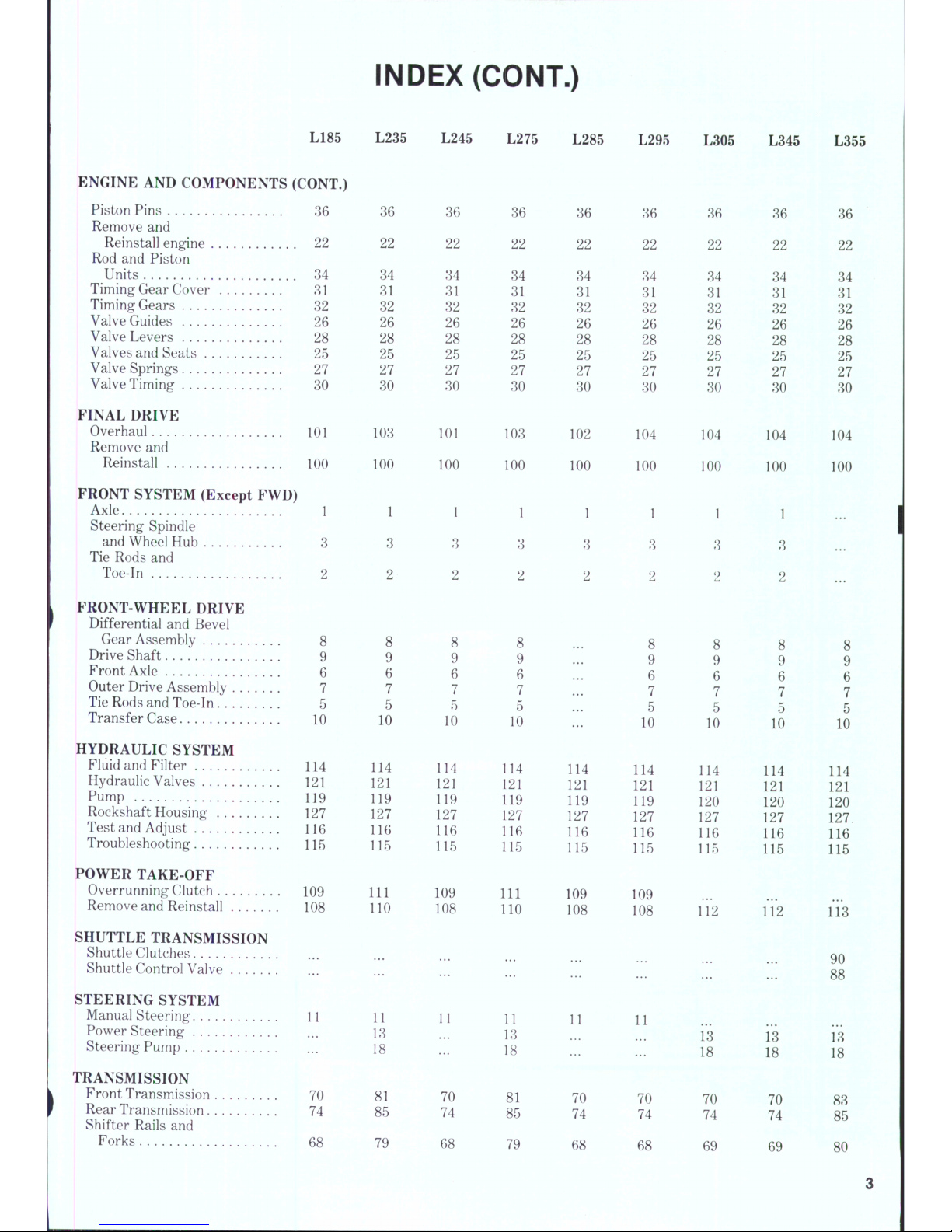
INDEX (By Starting Paragraph)
L185 L235 L245 L275 L285 L295 L305
L345
BRAKES
Adjustment 105
R&R and Overhaul 106
CLUTCH
Adjustment 63
Overhaul 65
Remove and
Reinstall 64
COOLING SYSTEM
Fan Shaft 59
Radiator 56
Thermostat
Water Pump
DIESEL FUEL SYSTEM
Fuel Filter 44
Glow Plugs 54
Injection Nozzles 50
Injection Pump 46
DIFFERENTIAL AND BEVEL GEARS
Differential Lock 97
Overhaul 92
Remove and Reinstall 91
ELECTRICAL SYSTEM
Alternator and
Regulator 60
Starter Motor and
Magnetic switch 62
Wiring Diagrams
ENGINE AND COMPONENTS
Cam Followers 29
Camshaft 33
Compression Release 24
Connecting Rods and
Bearings 38
Crankshaft and Main
Bearings 39
Crankshaft Rear Oil
Seal 40
Cylinder Head 23
Cylinder Sleeves 37
Flywheel 41
Oil Pump 42
Piston and Rings 35
64
38
39
64
38
39
64 64 64 64
38
39
38
39
38
39
38
39
64
L355
105
106
63
65
105
106
63
65
105
106
63
65
105
107
63
65
105
106
63
65
105
106
63
66
105
106
63
66
105
106
63
65
64
56
57
58
44
54
50
46
97
92
91
60
62
29
33
24
56
57
58
44
54
50
46
' 97
92
91
60
62
29
33
24
56
57
58
44
54
50
46
97
92
91
60
62
29
33
24
56
57
58
44
54
50
46
97
92
91
60
62
js
6 1
through
29
33
24
56
57
58
44
54
50
46
97
93
91
60
62
64
29
33
24
56
57
58
44
54
50
46
97
93
91
60
62
29
33
24
56
57
58
44
54
50
46
97
93
91
60
62
29
33
24
56
57
58
44
54
50
46
97
93
91
60
62
29
33
24
38
39
40
23
37
41
42
35
40
23
37
41
42
35
40
23
37
41
42
35
40
23
37
41
42
35
40
23
37
41
42
35
40
23
37
41
42
35
40
23
37
41
42
35
40
23
37
41
42
35
INDEX (CONT.)
L185
L235 L245
L275
L285
L295 L305 L345
L355
ENGINE AND COMPONENTS (CONT.)
Piston Pins 36
Remove and
Reinstall engine 22
Rod and Piston
Units 34
Timing Gear Cover 31
Timing Gears 32
Valve Guides 26
Valve Levers 28
Valves and Seats . 25
Valve Springs 27
Valve Timing 30
FINAL DRIVE
Overhaul 101
Remove and
Reinstall 100
FRONT SYSTEM (Except FWD)
Axle 1
Steering Spindle
and Wheel Hub 3
Tie Rods and
Toe-In 2
FRONT-WHEEL DRIVE
Differential and Bevel
Gear Assembly 8
Drive Shaft 9
Front Axle 6
Outer Drive Assembly 7
Tie Rods and Toe-In 5
Transfer Case 10
HYDRAULIC SYSTEM
Fluid and Filter 114
Hydraulic Valves 121
Pump 119
Rockshaft Housing 127
Test and Adjust 116
Troubleshooting 115
POWER TAKE-OFF
Overrunning Clutch 109
Remove and Reinstall 108
SHUTTLE TRANSMISSION
Shuttle Clutches
Shuttle Control Valve
STEERING SYSTEM
Manual Steering 11
Power Steering
Steering Pump
TRANSMISSION
Front Transmission 70
Rear Transmission 74
Shifter Rails and
Forks 68
22
34
31
32
26
28
25
27
30
103
100
1
3
2
8
9
6
7
5
10
114
121
119
127
116
115
111
110
36
22
34
31
32
26
28
25
27
30
101
100
1
3
2
8
9
6
7
5
10
114
121
119
127
116
115
109
108
36
22
34
31
32
26
28
25
27
30
103
100
1
3
2
8
9
6
7
5
10
114
121
119
127
116
115
111
110
36
22
34
31
32
26
28
25
27
30
102
100
1
3
2
114
121
119
127
116
115
109
108
36
22
34
31
32
26
28
25
27
30
104
100
1
3
2
8
9
6
7
5
10
114
121
119
127
116
115
109
108
36
22
34
31
32
26
28
25
27
30
104
100
1
3
2
8
9
6
7
5
10
114
121
120
127
116
115
112
36
22
34
31
32
26
28
25
27
30
104
100
1
3
2
8
9
6
7
5
10
114
121
120
127
116
115
112
36
22
34
31
32
26
28
25
27
30
104
100
...
8
9
6
7
5
10
114
121
120
127
116
115
113
11
13
18
81
85
11
70
74
00 CO —'
81
85
11
70
74
11
70
74
13
18
70
74
13
18
70
74
90
88
13
18
83
85
79
68 79
68
68
69 69
80
DUAL DIMENSIONS
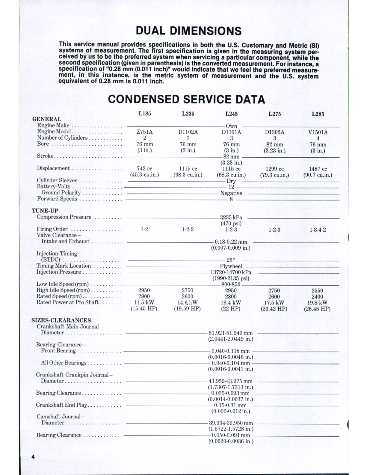
This service manual provides specifications in both the U.S. Customary and Metric (SI)
systems of measurement. The first specification is given in the measuring system perceived by us to be the preferred system when servicing a particuiar component, whiie the
second specification (given in parenthesis) is the converted measurement. For instance, a
specification of "0.28 mm (0.011 inch)" wouid indicate that we feei the preferred measurement, in this instance, is the metric system of measurement and the U.S. system
equivaient of 0.28 mm is 0.011 inch.
CONDENSED SERVICE DATA
L185 L235
GENERAL
Engine Make
Engine Model Z751A D1102A
Number of Cylinders 2 3
Bore 76 mm 76 mm
(3 in.) (3 in.)
Stroke
Displacement 743 cc 1115 cc
(45.3 cu.in.) (68.3 cu.in.)
Cylinder Sleeves
Battery-Volts
Ground Polarity
Forward Speeds
TUNE-UP
Compression Pressure —
FiringOrder 1-2 1-2-3
Valve Clearance-
Intake and Exhaust
Injection Timing
(BTDC) - . .
Timing Mark Location
Injection Pressure
Low Idle Speed (rpm)
High Idle Speed (rpm) 2950 2750
Rated Speed (rpm) 2800 2600
Rated Power at Pto Shaft 11.5 kW
14.61
kW
(15.45 HP) (19.59 HP)
SIZES-CLEARANCES
Crankshaft Main Journal-
Diameter
Bearing Clearance -
Front Bearing
All Other Bearings
Crankshaft Crankpin Journal -
Diameter
Bearing Clearance
Crankshaft End Play
Camshaft Journal -
Diameter
Bearing Clearance
L24S
Own —
DllOlA
3
76 mm
(3 in.)
—
82
mm —
(3.23 in,)
1115 cc
(68.3 cu.in.)
Dry —
12
—
Negative
8
L275 L285
-
3,235
kPa
(470 psi)
1-2-3
—
0.18-0.22
mm
(0.007-0.009 in.)
-25°
-
Flywheel
-13720-14700 kPa
(1990-2135 psi)
800-850
2950
2800
16.4 kW
(22 HP)
-51.921-51.940 mm
(2.0441-2.0449 in.)
-0.040-0.118 mm (0.0016-0.0046 in.)
—
0.040-0.104
m m -
(0.0016-0.0041 in.)
-43.959-43.975 mm
(1.7307-1.7313 in.)
-0.035-0.093 mm (0.0014-0.0037 in.)
—
0.15-0.31
mm -
(0.006-0.012 in.)
-39.934-39.950 mm
(1.5722-L5728 in.)
—
0.050-0.091
mm -
(0.0020-0.0036 in.)
D1302A
3
82 mm
(3.23 in.)
V1501A
4
76 mm
(3 in.)
1299 cc
(79.3 cu.in.)
1487 cc
(90.7 cu.in.)
1-2-3
1-3-4-2
2750
2600
17.5 kW
(23.42 HP)
2550
2400
19.8 kW
(26.45 HP)
CONDENSED SERVICE DATA (CONT.)
SIZES-CLEARANCES (CONT.)
^^^ ^ ^^^^ ^^^^ ^275
Cam He ig ht -
Intake
and
Exhaust
.
33.36
mm
(1.3134
in.)
Piston
Pin-
I^ia'^eter
23.002-23.011
mm
(0.9056-0.9059
in.)
Clearance
in Rod
-0.014-0.038
mm
(0.0006-0.0015
in.)
Valve Seat An gl e-
Intake
and
Exhaust
. 450
CAPACITIES
CrankcaseOil
3.8 L 6.1 L 6.1 L 6.1 L
r. ,• c. (4.0 qts.) (6.4 qts.) (6.4 qts.) (6.4 qts.)
CoolmgSystem
5.3 L 6.6 L 6.6 L 6.6 L
.
. (5.6 qts.) (7.0 qts.) (7.0 qts.) (7.0 qts.)
Iransmission-
2WD
22 L 24 L 22 L 24 L
,,,,^
(23 qts.) (25 qts.)
(23
qts.)
(25
qts.)
4WD
23 L 24 L 23 L 24 L
^,
.^
^ (24 qts.) (25 qts.) (24 qts.) (25 qts.)
PluidType
—
Kubota UDT Transmission Fluid
-
Front Axle Differential
Case(4WD)
1.1 L 2.3 L 1,1 L 2.6 L
™
. . ^ (1.2 qts.) (2.4 qts.) (1.2 qts.) (2.7 qts.)
FluidType
SAE
80
or
90 Gear Oil
Front Axle Outer Drive
Case (4WD)-Each
0.8 L 0.3 L 0.8 L 0.3 L
(0-8
qts.)
(0.3
qts.)
(0.8
qts.)
(0.3
qts.)
FluidType
SAE
80
or
90 Gear Oil
Steering Gear
Box
(Manual)
^0.3L
T.T
. (^-3 qt s. )
FluidType
SAE
80
or
90 Gear Oil
CONDENSED SERVICE DATA
L295
GENERAL
Engine Make
^__^
Engine Model D1301A
Number
of
Cylinders
3
Bore
' 82 mm
(3.23
in.)
Stroke
Displacement
1299 cc
(79.8 cu.in.)
Cylinder Sleeves
Battery-Volts
Ground Polarity
Forward Speeds
TUNE-UP
Compression Pressure
Firing Order
1-2-3
Valve Clearan ce-
Intake
and
Exhaust
Injection Timing (BTDC)
Timing Mark Location
Injection Pressure
L305
L345
-Own
D1301A
3
82
mm
(8.28
in.)
-82 mm
V1501A
4
76
mm
(8
in.)
(8.28
in.)
1299
CC
1487
CC
(79.8 cu.in.)
(90.7
cu.in.)
Dry
.
12
L285
8.9 L
(9.4
qts.)
7.0
L
(7.4
qts.)
27
L
(29
qts.)
L355
V1702A
4
82
mm
(8.28
in.)
1782
CC
(105.6 cu.in.)
-
Negative
8
—
1-2-8
-8285kPa
(470
psi)
1-8-4-2
1-8-4-2
-0.18-0.22mm
(0.007-0.009
in.)
25°
-
Flywheel
-18720-14700
kPa-
(1990-2185
psi)
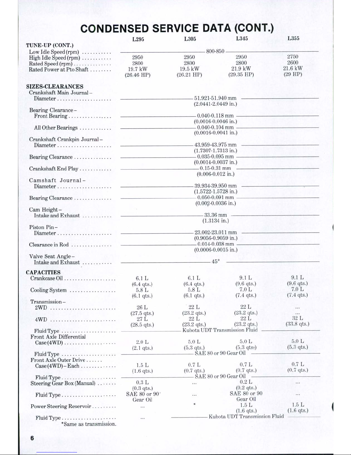
CONDENSED SERVICE DATA (CONT.)
L295
TUNE-UP (CONT.)
Low Idle Speed (rpm)
High Idle Speed (rpm) . . .
Rated Speed (rpm)
Rated Power at Pto Shaft
2950
2800
19.7 kW
(26.46 HP)
SIZES-CLEARANCES
Crankshaft Main Journal -
Diameter
Bearing Clearance-
Front Bearing
All Other Bearings
Crankshaft Crankpin Journal-
Diameter
Bearing Clearance
Crankshaft End Play
Camshaft J o u rn a l -
Diameter
Bearing Clearance
Cam Height-
Intake and Exhaust
Piston Pin-
Diameter
Clearance in Rod
Valve Seat A ng le -
Intake and Exhaust
CAPACITIES
Crankcase Oil 6.1 L
(6.4 qts.)
Cooling System 5.8 L
(6.1 qts.)
Transmission -
2WD 26 L
(27.5 qts.)
4WD 27 L
(28.5 qts.)
Fluid Type
Front Axle Differential
Case(4WD) 2.0 L
(2.1 qts.)
Fluid Type
Front Axle Outer Drive
Case(4WD)-Each 1.5 L
(1.6 qts.)
Fluid Type
Steering Gear Box (Manual) 0.3 L
(0.3 qts.)
Fluid Type SAE 80 or 90'
Gear Oil
Power Steering Reservoir
Fluid Type
*Same as transmission.
L305
L345
-800-8502950
2800
19.5 kW
(26.21 HP)
2950
2800
21.9 kW
(29.35 HP)
-51.921-51.940 mm
(2.0441-2.0449 in.)
-0.040-0.118 mm (0.0016-0.0046 in.)
—
0.040-0.104
mm -
(0.0016-0.0041 in.)
—
43.959-43.975 mm
(1.7307-1.7313 in.)
—
0.035-0.095
mm -
(0.0014-0.0037 in.)
—
0.15-0.31
mm -
(0.006-0.012 in.)
-39.934-39.950 mm
(1.5722-1.5728 in.)
—
0.050-0.091
mm -
(0.002-0.0036 in.)
-33.36 mm
(1.3134 in.)
-23.002-23.011 mm
(0.9056-0.9059 in.)
—
0.014-0.038
mm -
(0.0006-0.0015 in.)
-45°
6.1 L :
(6.4 qts.)
(6.1 qts.) • :
22 L
(23.2 qts.)
22 L
(23.2 qts.)
-
Kubota UDT Transmission Fluid
5.0 L 5.0 L
(5.3 qts.) (5.3 qts:)
SAE 80 or 90 Gear Oil —
9.1
(9.6
7.C
(7.4
22
(23.2
22
(23.2
L
qts.)
)L
qts.)
L
qts.)
L
qts.)
0.7 L 0.7 L
(0.7 qts.) (0.7 qts.)
SAE 80 or 90 Gear
Oil
—
0.2 L
L355
2750
2600
21.6 kW
(29 HP)
9.1 L
(9.6 qts.)
7.0 L
(7.4 qts.)
32 L
(33.8 qts.)
5.0 L
(5.3 qts.)
0.7 L
(0.7 qts.)
(0.2 qts.)
SAE 80 or 90
Gear Oil
1.5 L
(1.6 qts.)
Kubota UDT Transmission Fluid
1.5 L
(1.6 qts.)
6
SHOP MANUAL
Paragraphs 1-3
FRONT SYSTEM
(TWO-WHEEL DRIVE)
FRONT AXLE
All Models So Equipped
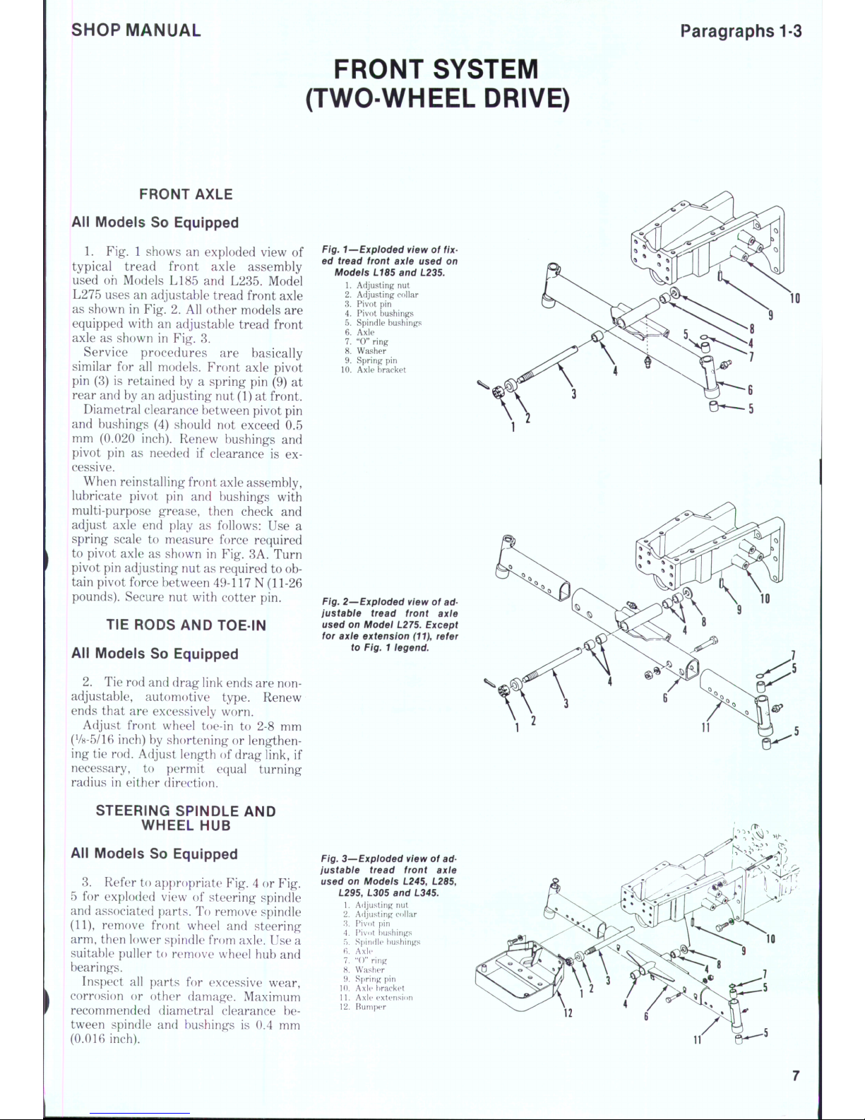
1.
Fig. 1 shows an exploded view of
typical tread front axle assembly
used oh Models L185 and L285. Model
L275 uses an adjustable tread front axle
as shown in Fig. 2. All other models are
equipped with an adjustable tread front
axle as shown in Fig. 8.
Service procedures are basically
similar for all models. Front axle pivot
pin (8) is retained by a spring pin (9) at
rear and by an adjusting nut (1) at front.
Diametral clearance between pivot pin
and bushings (4) should not exceed 0.5
mm (0.020 inch). Renew bushings and
pivot pin as needed if clearance is excessive.
When reinstalling front axle assembly,
lubricate pivot pin and bushings with
multi-purpose grease, then check and
adjust axle end play as follows: Use a
spring scale to measure force required
to pivot axle as shown in Fig. 8A. Turn
pivot pin adjusting nut as required to obtain pivot force between 49-117 N (11-26
pounds). Secure nut with cotter pin.
TIE RODS AND TOE-IN
All Models So Equipped
2.
Tie rod and drag link ends are nonadjustabie, automotive type. Renew
ends that are excessively worn.
Adjust front wheel toe-in to 2-8 mm
(V8-5/16 inch) by shortening or lengthening tie rod. Adjust length of drag link, if
necessary, to permit equal turning
radius in either direction.
STEERING SPINDLE AND
WHEEL HUB
All Models So Equipped
8. Refer to appropriate Fig. 4 or Fig.
5 for exploded view of steering spindle
and associated parts. To remove spindle
(11),
remove front wheel and steering
arm, then lower spindle from axle. Use a
suitable puller to remove wheel hub and
bearings.
Inspect al! parts for excessive wear,
corrosion or other damage. Maximum
recommended diametral clearance between spindle and bushings is 0.4 mm
(0.016 inch).
Fig. 1—Expioded view of
fix-
ed tread front axle used on
Motfe/s L185 and L235.
1.
Adjusting nut
2.
Adjusting collar
3.
Pivot pin
4.
Pivot bushings
5.
Spindle bushings
6. Axle
7.
"0" ring
8. Washer
9. Spring pin
10.
Axle bracket
en—5
Fig.
2—Expioded view of ad-
justabie tread front axie
used on Modei
L275.
Except
for axle extension
(11),
refer
to Fig. 1 legend.
Fig.
3—Expioded view of adjustabie tread front axle
used on Modeis L245, L285,
L295, L305 and L345.
1.
Af ljusting nut
2.
Ad justi ng collar
3.
Pivot i)in
4.
Pivot bu shings
f).
Spin dle bu shing s
fi. A xle
7.
" ()" ring
8. Wa sher
9. Sp ring pin
10.
Axle b racke t
11.
Axk* e xtens ion
12.
[^um[)er
Paragraphs 4-6
KUBOTA
^
11
Fig. BA—Use a spring scafe
to measure force required to
pivot axie.
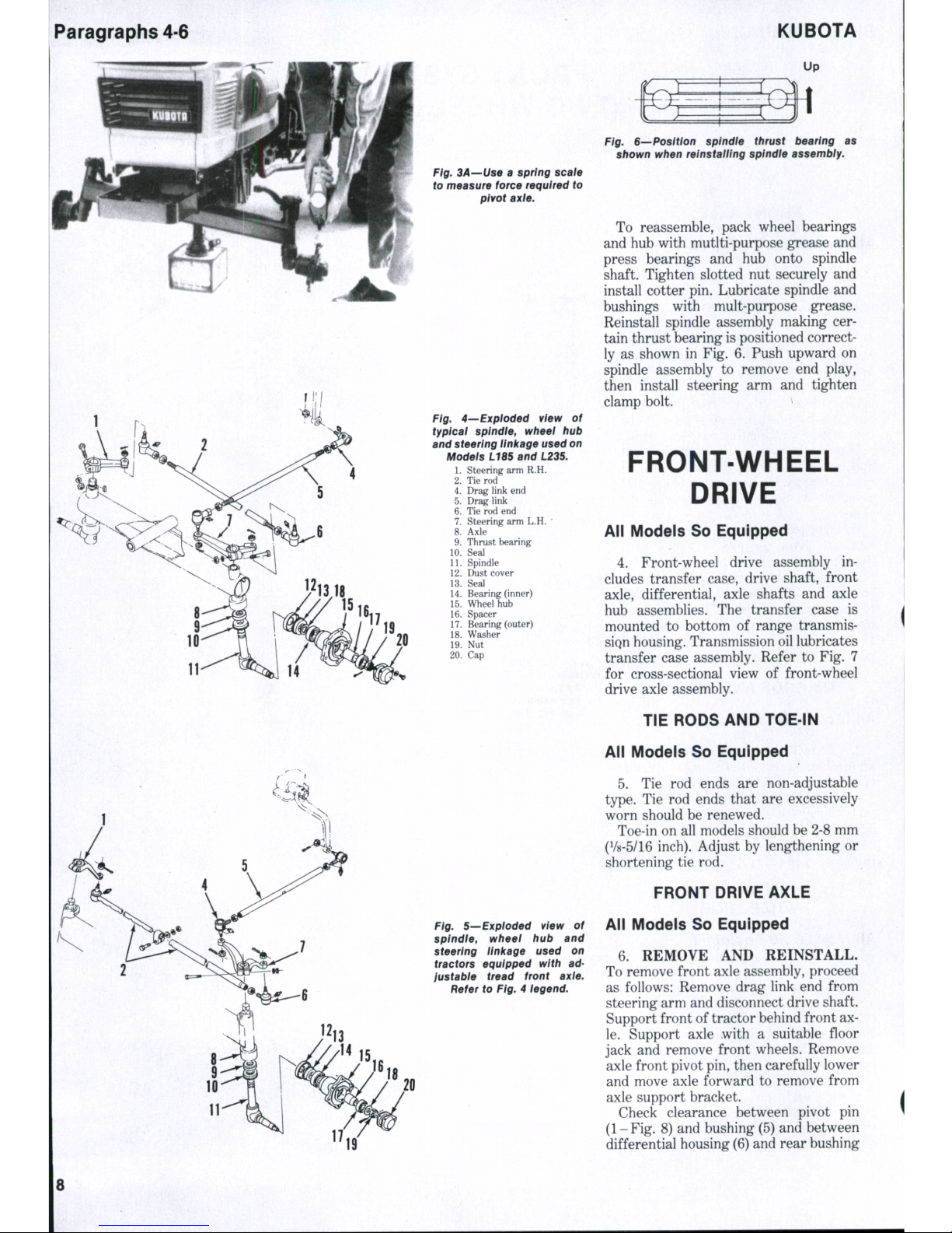
Fig. 4—'Expioded view of
typicai spindie, wheei hub
and steering iinkage used on
Modeis L18S and L23S.
1.
Steering arm R.H.
2.
Tie rod
4.
Drag link end
5.
Drag link
6. Tie rod end
7.
Steering arm L.H.
*
8. Axle
9. Thrust bearing
10.
Seal
11.
Spindle ,
12.
Dust cover
13.
Seal
14.
Bearing (inner)
15.
Wheel hub
16.
Spacer
17.
Bearing (outer)
18.
Washer
19.
Nut
20.
Cap
Fig. 5—Expioded view of
splndie, wheei hub and
steering ilni(age used on
tractors equipped with ad-
justabie tread front axie.
Refer to Fig. 4 iegend.
Fig. S—Position spindie thrust bearing as
shown when reinstaiiing spindie assembiy.
To reassemble, pack wheel bearings
and hub with mutlti-purpose grease and
press bearings and hub onto spindle
shaft. Tighten slotted nut securely and
install cotter pin. Lubricate spindle and
bushings with mult-purpose grease.
Reinstall spindle assembly making certain thrust bearing is positioned correctly as shown in Fig. 6. Push upward on
spindle assembly to remove end play,
then install steering arm and tighten
clamp bolt. >
FRONT-WHEEL
DRIVE
All Models So Equipped
4.
Front-wheel drive assembly includes transfer case, drive shaft, front
axle,
differential, axle shafts and axle
hub assemblies. The transfer case is
mounted to bottom of range transmissiQn housing. Transmission oil lubricates
transfer case assembly. Refer to Fig. 7
for cross-sectional view of front-wheel
drive axle assembly.
TIE RODS AND TOE-IN
All Models So Equipped
5.
Tie rod ends are non-adjustable
type.
Tie rod ends that are excessively
worn should be renewed.
Toe-in on all models should be 2-8 mm
(1/8-5/16 inch). Adjust by lengthening or
shortening tie rod.
FRONT DRIVE AXLE
All Models So Equipped
6. REMOVE AND REINSTALL.
To remove front axle assembly, proceed
as follows: Remove drag link end from
steering arm and disconnect drive shaft.
Support front of tractor behind front ax-
le.
Support axle with a suitable floor
jack and remove front wheels. Remove
axle front pivot pin, then carefully lower
and move axle forward to remove from
axle support bracket.
Check clearance between pivot pin
(1-Fig. 8) and bushing (5) and between
differential housing (6) and rear bushing
SHOP MANUAL
Paragraph
7
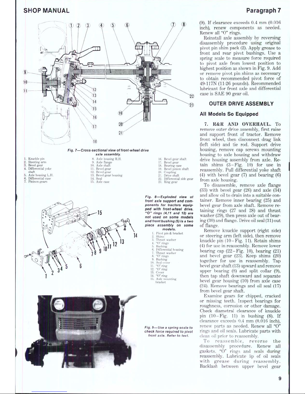
Fig. 7—Cross-sectional view
of
front-wheel
drive
axie assembly.
1. Knuckle
pin 8.
Axle housing
R.H.
2.
Steering arm 9. Axle flange
3.
Bevel gear 10. Axle shaft
4.
Differential yoke 11. Bevel gear
shaft ' 12. Bevel gear
5.
Axle housing L.H. 13. Bevel gea r housing
6. Differential ease 14. Seal
7.
Pininon g ears 15. Axle case
16.
Bevel gear shaft
17.
Bevel gear
18.
Bearing case
19.
Bevel pinion shaft
20.
Coupling
21.
Drive shaft
22.
Differential side gear
23.
Ring gear
Fig. 8—Expioded view
of
front axte support
and
com-
ponents
for
tractors equip-
ped with front-wheel drive.
"0" rings (4,11
and
12)
are
not used
on
some models
and
front
bushing
(5)
is a two
piece assembly
on
some
models.
1.
Pivot pin & bracket
2.
Shims
3.
Thrust washer
4.
"()" rings
5.
Bushing
6. Differential housing
7.
Thrust washer
8. "(T' rings
9. Bushing
10.
Seal cover
11.
"0 " ring
12.
"O "ring
13.
Cover
14.
"0 " ring
15.
Axle mounting
bracket
Fig.
9—Use a spring scale
to
check force required
to
pivot
front axle. Refer
to
text
(9).
If
clearance exceeds
0.4 mm
(0.016
inch),
renew components
as
needed.
Renew
all
"0" rings.
Reinstall axle assembly
by
reversing
disassembly procedure using original
pivot
pin
shim pack (2). Apply grease
to
front
and
rear pivot bushings.
Use a
spring scale
to
measure force required
to pivot axle from lowest position
to
highest position
as
shown
in
Fig.
9.
Add
or remove pivot
pin
shims
as
necessary
to obtain recommended pivot force
of
49-117N (11-26 pounds). Recommended
lubricant
for
front axle
and
differential
case
is
SAE
90
gear
oil.
OUTER DRIVE ASSEMBLY
All Models
So
Equipped
7.
R&R AND
OVERHAUL,
To
remove outer drive assembly, first raise
and support front
of
tractor. Remove
front wheel, then disconnect drag link
(left side)
and tie rod.
Support drive
housing, remove
cap
screws mounting
housing
to
axle housing
and
withdraw
drive housing assembly from axle.
Re-
tain shims (3-Fig.
10) for use in
reassembly. Pull differential yoke shaft
(4) with bevel gear
(7) and
bearing
(6)
from axle housing.
To disassemble, remove axle flange
(33) with bevel gear
(26) and
axle
(34)
and allow
oil
to
drain into a suitable
con-
tainer. Remove inner bearing
(25) and
bevel gear from axle shaft. Remove
re-
taining rings
(27 nnd 28) and
thrust
washer (29), then press axle
out
of
bear-
ing
(30)
and
flange. Drive oil seal
(31)
out
of flange.
Remove knuckle support (right side)
or steering
arm
(left side), then remove
knuckle
pin
(10-Fig.
11).
Retain shims
(4)
for
use
in
reassembly. Remove lower
bearing
cap
(22-Fig.
10),
bearing
(21)
and bevel gear
(23).
Keep shims
(20)
together
for use In
reassembly.
T'ap
bevel gear shaft
(13)
upward
and
remove
upper bearing
(8) and
split collar
(9),
then
tap
shaft downward
and
separate
bevel gear housing
(10)
from axle case
(24).
Remove bearings
and oil
seal
(17)
from bevel gear shaft.
Examine gears
for
chipped, cracked
or missing teeth. Inspect bearings
for
roughness, corrosion
or
other damage.
Check diametral clearance
of
knuckle
pin (1 0-Fig.
11) in
bushing
(8). If
clearance exceeds
0.4 mm
(0.016 inch),
renew parts
as
needed. Renew
all " 0"
rings
and oil
seals. Lubricate parts with
clean
oil
prior
to
reassembly.
To rea s semb le, r e ver s e
the
disassembly procedure. Renew
all
gaskets.
"0"
rings
and
seals during
reassembly. Lubricate
lip of oil
seals
with gre ase d ur ing reas sembly.
Backlash between upper bevel gear
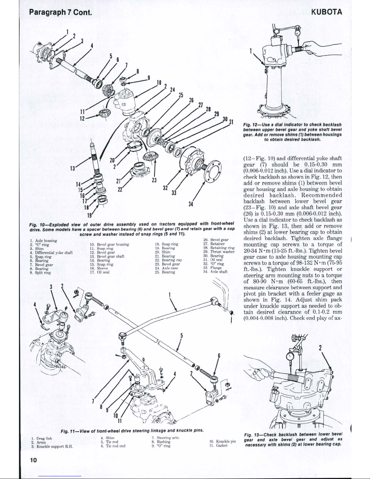
Paragraph 7 Cont.
KUBOTA
34
Fig. lO—Bxploded view of outer drive assembiy used on tractors equipped with front-wheel
drive. Some modeis have a spacer between bearing (6) and bevel gear (7) and retain gear with a cap
screw and washer Instead of snap rings (5 and 11).
1.
Axle housing
2.
"0" ring
3.
Shim
4.
Differential yoke shaft
5.
Snap ring
6. Bearing
7.
Bevel gear
8. Bearing
9. Split ring
10.
Bevel gear housing
11.
Snap ring
12.
Bevel gear
13.
Bevel gear shaft
14.
Bearing
15.
Snap ring
16.
Sleeve
17.
Oil seal
18.
Snap ring
19.
Bearing
20.
Shim
21.
Bearing
22.
Bearing cap
23.
Bevel gear
24.
Axle case
25.
Bearing
26.
27.
28.
29.
30.
31.
32.
33.
M.
Bevel gear
Retainer
Retaining ring
Thrust washer
Bearing
Oil seal
"0"
ring
Flange
Axle shaft
11
Pfg.
tt~ We i¥ of front-wheel drive steering linkage and knuckle pins.
1.
Drag link
2.
Arms
3.
Knuckle support R.H.
Fig. 12—Use a dial indicator to check backiash
between upper bevel gear and yoke shaft bevei
gear.
Add or remove shims (1) between housings
to obtain desired backlash.
(12-Fig. 10) and differential yoke shaft
gear (7) should be 0.15-0.30 mm
(0.006-0.012 inch). Use a dial indicator to
check backlash as shown in Fig. 12, then
add or remove shims (1) between bevel
gear housing and axle housing to obtain
desired ba cklash. Recom mended
backlash between lower bevel gear
(23-Fig. 10) and axle shaft bevel gear
(26) is 0.15-0.30 mm (0.006-0.012 inch).
Use a dial indicator to check backlash as
shown in Fig. 13, then add or remove
shims (2) at lower bearing cap to obtain
desired backlash. Tighten axle flange
mounting cap screws to a torque of
20-34 N-m (15-25 ft.-lbs.). Tighten bevel
gear case to axle housing mounting cap
screws to a torque of 98-132 N-m (75-95
ft.-lbs.).
Tighten knuckle support or
steering arm mounting nuts to a torque
of 80-90 N-m (60-65 ft.-lbs.), then
measure clearance between support and
pivot pin bracket with a feeler gage as
shown in Fig. 14. Adjust shim pack
under knuckle support as needed to ob-
tain desired clearance of 0.1-0.2 mm
(0.004-0.008 inch). Check end play of ax-
4.
Shim
5.
Tie rod
6. Tie rod end
7.
Steering arm
8. Bushing
9. "0" ring
10.
Knuckle pin
11.
Gasket
Fig. 13—Check backlash between iower bevel
gear and axle bevei gear and adjust as
necessary with shims (2) at lower bearing cap.
10
SHOP MANUAL
Paragraph 8
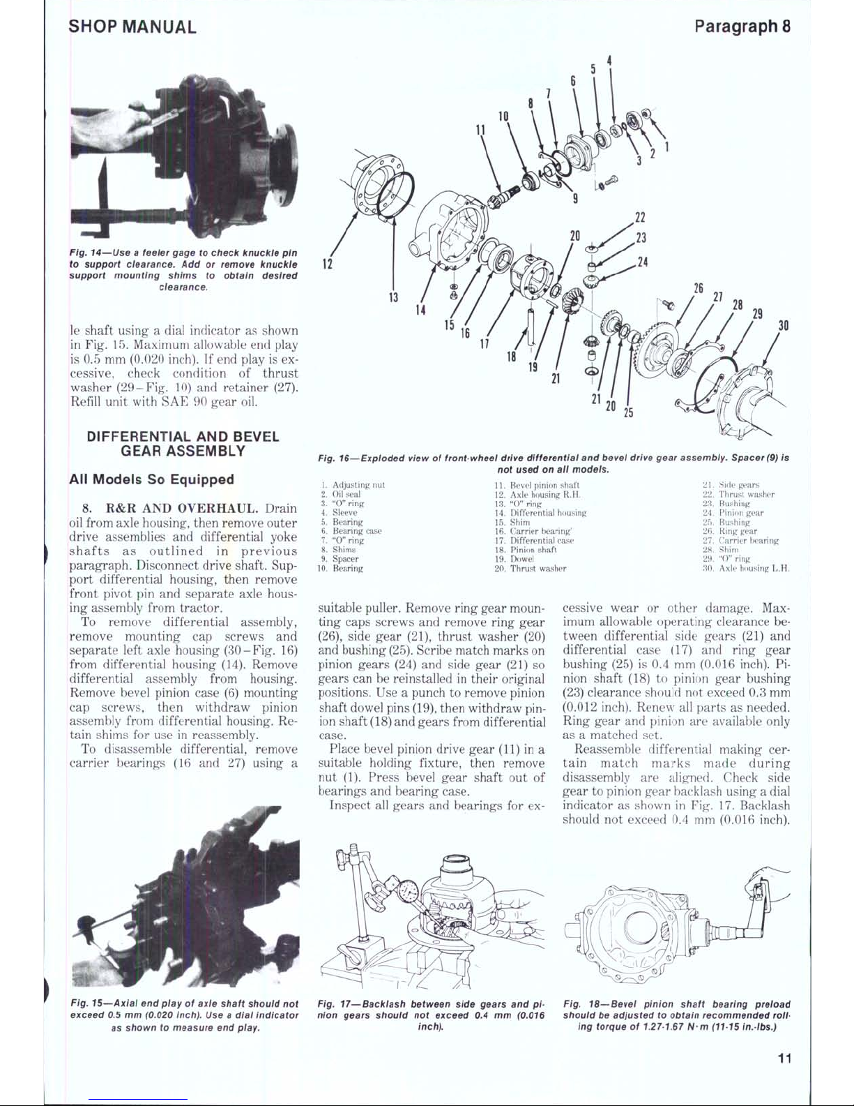
Fig. 14—Use a feeier gage to check knuckle pin
to support clearance. Add or remove knuckie
support mounting shims to obtain desired
ciearance.
le shaft using a dial indicator as shown
in Fig. 15. Maximum allowable end play
is 0.5 mm (0.020 inch). If end play is ex-
cessive, check condition of thrust
washer (29-Fig. 10) and retainer (27).
Refill unit with SAE 90 gear oil.
DIFFERENTIAL AND BEVEL
GEAR ASSEMBLY
All Models So Equipped
8. R&R AND OVERHAUL. Drain
oil from axle housing, then remove outer
drive assemblies and differential yoke
shafts as outlined in previous
paragraph. Disconnect drive shaft. Support differential housing, then remove
front pivot pin and separate axle hous-
ing assembly from tractor.
To remove differential assembly,
remove mounting cap screws and
separate left axle housing (30-Fig. 16)
from differential housing (14). Remove
differential assembly from housing.
Remove bevel pinion case (6) mounting
cap screws, then withdraw pinion
assembly from differential housing. Retain shims for use in reassembly.
To disassemble differential, remove
carrier bearings (16 and 27) using a
21
20
25
Fig. 16--Exploded view of front-wheel drive differentiai and bevei drive gear assembiy. Spacer (9) is
not used on ail modeis.
1.
Adjusting nut
2.
Oil seal
3.
"0" ring
4.
Sleeve
5.
Bearing
6. Bearing ease
7.
"0" ring
8. Shims
9. Spacer
10.
Bearing
11.
Bevel pinion shaft
12.
Axle housing R.H.
13.
"0" ring
14.
Differential housing
15.
Shim
16.
Carrier bearing'
17.
Differential case
18.
Pinion shaft
19.
Dowel
20.
Thrust washer
21.
Side gears
22.
Thrust washer
23.
Bushing
24.
Pinion gear
25.
Bushing
2fi.
Ring gear
27.
Carrier tearing
28.
Shim
29.
"0" ring
'M).
Axle housing L.H.
suitable puller. Remove ring gear mounting caps screws and remove ring gear
(26),
side gear (21), thrust washer (20)
and bushing
(25).
Scribe match marks on
pinion gears (24) and side gear (21) so
gears can be reinstalled in their original
positions. Use a punch to remove pinion
shaft dowel pins
(19),
then withdraw pin-
ion shaft
(18)
and gears from differential
case.
Place bevel pinion drive gear (11) in a
suitable holding fixture, then remove
nut (1). Press bevel gear shaft out of
bearings and bearing case.
Inspect all gears and bearings for ex-
cessive wear or other damage. Maximum allowable operating clearance between differential side gears (21) and
differential case (17) and ring gear
bushing (25) is 0.4 mm (0.016 inch). Pinion shaft (18) to pinion gear bushing
(23) clearance should not exceed 0.3 mm
(0.012 inch). Renew all parts as needed.
Ring gear and pinion are available only
as a matched set.
Reassemble differential making certain match mark s made during
disassembly are aligned. Check side
gear to pinion gear backlash using a dial
indicator as shown in Fig. 17. Backlash
should not exceed 0.4 mm (0.016 inch).
Fig. 15—Axial end piay of axie shaft shouid not
exceed 0.5 mm (0.020 inch). Use a dial indicator
as shown to measure end
piay.
Fig. 17^Backiash between side gears and pinion gears shouid not exceed 0.4 mm (0.016
inch).
Fig. 18—'Bevei pinion shaft bearing preload
should be adjusted to obtain recommended
roil-
ing torque of
1.27-167
N-m (11-15 in.tbs.)
11
Paragraph 8 Cont.
KUBOTA
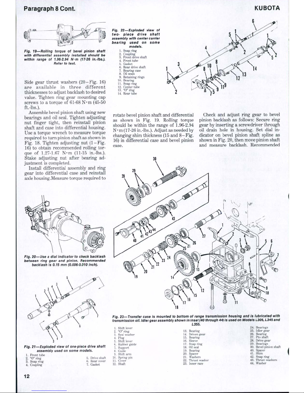
Fig. 19—Rolling torque of bevel ptnton shaft
with differential assembly Instatted shouid be
within range of 1.96-2.94 N-m (17-26 tn.-tbs.).
Refer to text
Side gear thrust washers (2 0-Fig. 16)
are available in three different
thicknesses to adjust backlash to desired
value. Tighten ring gear mounting cap
screws to a torque of 61-68 N-m (45-50
ft.-lbs.).
Assemble bevel pinion shaft using new
bearings and oil seal. Tighten adjusting
nut finger tight, then reinstall pinion
shaft and case into differential housing.
Use a torque wrench to measure torque
required to turn pinion shaft as shown in
Fig. 18. Tighten adjusting nut (1-Fig.
16) to obtain recommended rolling tor-
que of
1.27-1.67
N-m (11-15 in.-lbs.).
Stake adjusting nut after bearing ad-
justment is completed.
Install differential assembly and ring
gear into differential case and reinstall
axle housing.Measure torque required to
Fig. 20—Use a diai indicator to check backlash
between ring gear and pinion. Recommended
backlash Is 0.15 mm
(0.006-0.010
inch).
Fig. 21—Exploded view of one piece drive shaft
assembly used on some modets.
1.
Front tube
2.
"0" ring 5. Drive shaft
3.
Snap ring 6. Rear cover
4.
Coupling 7. Gasket
Ftg. 22—Exploded view of
two-
piece drive shaft
assembly
with center carrier
bearing used on some
models.
1.
Snap ring
2.
Coupling
3.
Front drive shaft
4.
Front tube
5.
Gasket
6. Rear drive shaft
7.
Bearing case
8. Oil seals
9. Retaining rings
10.
Bearing
11.
Snap ring
12.
Center tube
13.
"0" ring
14.
Rear tube
rotate bevel pinion shaft and differential
as shown in Fig. 19. Rolling torque
should be within the range of
1.96-2.94
N-m (17-26
in.-lbs.).
Adjust as needed by
changing shim thickness (15 and 8- Fig.
16) in differential case and bevel pinion
case.
Check and adjust ring gear to bevel
pinion backlash as follows: Secure ring
gear by inserting a screwdriver through
oil drain hole in housing. Set dial indicator on bevel pinion shaft spline as
shown in Fig. 20, then move pinion shaft
and measure backlash. Recommended
II
Fig. 23—Transfer case is mounted to bottom of range transmission housing and is lubricated with
transmission ott.
Idler
gear assembly shown in Inset
(40
through
44)
is used on Modeis
L305,
L345
and
L355.
1.
Shift lever
2.
"0" ring
3.
Seal washer
4.
Plug
5.
Shift lever
6. Rubber guide
7.
Support
8. Guide
9. Shift arm
10.
Spring pin
11.
Cover
12.
Shaft
13.
Bearing
14.
Driven gear
15.
Bearing
16.
Sleeve
17.
Snap ring
18.
Oil seal
19.
Bearing
20.
Spacer
21.
Washers
22.
Thrust washer
23.
Inner race
24.
Bearings
25.
Idler gear
26.
Bearing
27.
Pto shaft
28.
Drive gear
29.
Bearings
30.
Bevel pinion shaft
40.
Spacer
41.
Shim
42.
Snap ring
43.
Thrust washers
44.
Washer
12
SHOP MANUAL
Paragraphs 9-12
backlash
is
0.15-0.25
mm
(0.006-0.010
inch).
If
measured backlash is excessive,
decrease shims
(15 - Fig.
16)
on differen-
tial case side and add shims (28)
of
same
thickness between left axle housing and
differential case.
If
backlash
is
insuffi-
cient, decrease shims (28) and
add
same
thickness
to
shims (15).
Complete reassembly
and
installation
of axle assembly. Refill axle housing
with
SAE 90
gear
oil.
DRIVE SHAFT
All Models
So
Equipped
9. Models L305, L345 and L355 use
a
two-piece drive shaft with a center
car-
rier bearing (Fig.
22). All
other models
use a one-piece drive shaft
as
shown
in
Fig. 21.
Removal
of
drive shaft consists
of
removing mounting screws from drive
shaft tubes, disengaging retaining rings
and sliding drive shaft
out of
couplers.
Remove center carrier bearing
and oil
seals
on
models
so
equipped.
Inspect shaft splines
and
couplers
for
excessive wear
or
other damage.
Reinstall drive shaft
by
reversing
removal procedure.
TRANSFER CASE
All Models
So
Equipped
10.
R&R AND OVERHAUL. Drive
gear (28 -
Fig.
28) and idler gear (25) are
located
in
range transmission housing.
Refer
to
appropriate transmission
sec-
tion
for
service procedures.
To service transfer case, first drain
oil
from transmission housing. Disconnect
drive shaft
and
shift linkage. Remove
transfer case mounting
cap
screws
and
lower unit from transmission housing.
To disassemble, remove
oil
seal
(18),
retaining ring
(17) and
plug
(4). Tap
shaft (12)
out
front
of
case
and
remove
gear (14). Drive pin (10) out
of
shift arm
(9)
and
remove shift lever (1).
To reas s embl e , reve r se
the
disassembly procedure. Apply liquid
gasket maker
to
surfaces
of
drive case
mounting gasket when reinstalling.
STEERING SYSTEM
MANUAL STEERING
All Models
So
Equipped
All models equipped with manual
steering box
use a
recirculating ball
nut
steering gear similar
to
type shown
in
P^ig.
24.
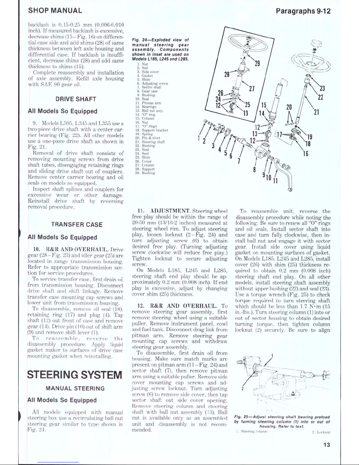
Fig. 24—Exploded view
of
manual steering gear
assembiy. Components
shown
in
inset
are
used
on
Models L185, L245 and
L28S.
1.
Nut
2.
Nut
3.
Side cover
4.
Gasket
5.
Shim
6. Adjusting screw
7.
Sector shaft
8. Gear case
9. Bushing
10.
Seal
11.
Pitman arm
12.
Bearings
13.
Ball nut assy.
14.
" 0" ring
15.
Column
16.
Nut
17.
" 0" rings
18.
Support bracket
19.
Spring
20.
Pin & rivet
21.
Ste ering shaft
22.
Bushing
23.
Seal
24.
Seai
25.
Shim
26.
Cover
27.
Column
28.
Support
29.
Bushing
11.
ADJUSTMENT. Steering wheel
free play should
be
within
the
range
of
20-50
mm
(13/16-2 inches) measured
at
steering wheel
rim. To
adjust steering
play, loosen locknut (2-Fi g.
24) and
turn adjusting screw
(6) to
obtain
desired free play. (Turning adjusting
screw clockwise will reduce free play.)
Tighten locknut
to
secure adjusting
screw.
On Models LI85, L245
and
L285,
steering shaft
end
play should
be ap-
proximately
0.2
mm (0.008 inch).
If
end
play
is
excessive, adjust
by
changing
cover shim (25) thickness.
12.
R&R AND
OVERHAUL.
To
remove steering gear assembly, first
remove steering wheel using a suitable
puller. Remove instrument panel, cowl
and fuel tank. Disconnect drag link from
pitman
arm.
Remove steering gear
mounting
cap
screws
and
withdraw
steering gear assembly.
To disassemble, first drain
oil
from
housing. Make sure match marks
are
present on pitman arm
(1 1 -
Fig.
24) and
sector shaft
(7),
then remove pitman
arm using a suitable puller. Remove side
cover mounting
cap
screws
and adjusting screw locknut. Turn adjusting
screw (6)
to
remove side cover, then
tap
sector shaft
out
side cover opening.
Remove steering column
and
steering
shaft with hall
nut
assembly (13). Ball
nut
is
available only
as an
assernhknl
unit
and
disassembly
is not
recom-
mended.
To reassemble unit, reverse
the
disassembly procedure while noting^
the
following: Be sure
to
renew all "0" rings
and
oil
seals. Install sector shaft into
case
and
turn fully clockwise, then
in-
stall ball
nut and
-engage
it
with sector
gear. Install side cover using liquid
gasket
on
mounting surfaces
of
gasket.
On Models L185, L245 and L285, install
cover
(26)
with shim
(25)
thickness
re-
quired
to
obtain
0.2 mm
(0.008 inch)
steering shaft
end
play.
On all
other
models, install steering shaft assembly
without upper bushing (22) and seal (23).
Use a torque wrench (Fig. 25)
to
check
torque required
to
turn steering shaft
which should
be
less than
1.7 N-m (15
in.-lbs.).
Turn steering column (1) into
or
out
of
sector housing
to
obtain desired
turning torque, then tighten column
locknut
(2)
securely.
Be
sure
to
align
Fig. 25—Adjust steering shaft bearing preload
by turning steering coiumn
(1)
into
or out of
housing. Refer
to
text
1.
Steering colunm 2 Ijocknut
13
Paragraphs 13-14 KUBOTA
match marks when reinstalling pitman
arm. Refill unit with approximately 0.2
L (% pint) of SAE 90 gear oil.
Reinstall steering unit on tractor and
adjust steering wheel free play as
previously outlined.
POWER STEERING
Integral Type
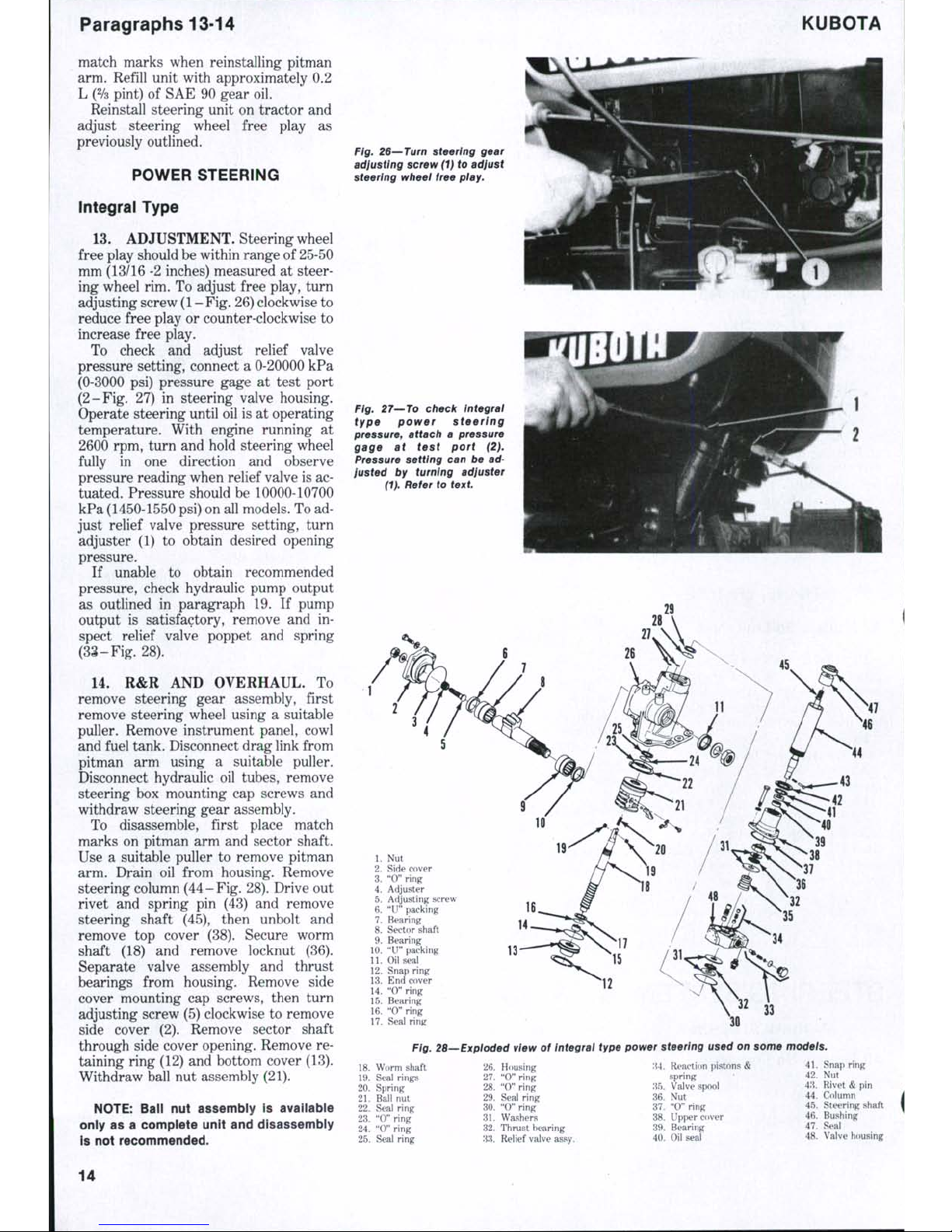
13.
ADJUSTMENT. Steering wheel
free play should be within range of 25-50
mm (13/16-2 inches) measured at steering wheel rim. To adjust free play, turn
adjusting screw
(1 - Fig.
26) clockwise to
reduce free play or counter-clockwise to
increase free play.
To check and adjust relief valve
pressure setting, connect a 0-20000 kPa
(0-3000 psi) pressure gage at test port
(2-Fig. 27) in steering valve housing.
Operate steering until oil is at operating
temperature. With engine running at
2600 rpm, turn and hold steering wheel
fully in one direction and observe
pressure reading when relief valve is ac-
tuated. Pressure should be 10000-10700
kPa (1450-1550 psi) on all models. To ad-
just relief valve pressure setting, turn
adjuster (1) to obtain desired opening
pressure.
If unable to obtain recommended
pressure, check hydraulic pump output
as outlined in paragraph 19. If pump
output is satisfactory, remove and inspect relief valve poppet and spring
(33-Fig.28).
14.
R&R AND OVERHAUL. To
remove steering gear assembly, first
remove steering wheel using a suitable
puller. Remove instrument panel, cowl
and fuel tank. Disconnect drag link from
pitman arm using a suitable puller.
Disconnect hydraulic oil tubes, remove
steering box mounting cap screws and
withdraw steering gear assembly.
To disassemble, first place match
marks on pitman arm and sector shaft.
Use a suitable puller to remove pitman
arm. Drain oil from housing. Remove
steering column
(44 - Fig.
28). Drive out
rivet and spring pin (43) and remove
steering shaft (45), then unbolt and
remove top cover (38). Secure worm
shaft (18) and remove locknut (36).
Separate valve assembly and thrust
bearings from housing. Remove side
cover mounting cap screws, then turn
adjusting screw (5) clockwise to remove
side cover (2). Remove sector shaft
through side cover opening. Remove retaining ring (12) and bottom cover (13).
Withdraw ball nut assembly (21).
NOTE:
Ball nut assembly is available
only as a complete unit and disassembly
Is not recommended.
Fig. 26—Turn steering gear
adjusting screw (1) to adjust
steering wheel free
play.
Fig. 27—To check integral
type power steering
pressure, attach a pressure
gage at test port (2).
Pressure setting can be adjusted by turning adjuster
(1).
Refer to text
1.
Nut
2.
Side cover
3.
"0" ring
4.
Adjuster
5.
Adjusting screw
6. "U" packing
7.
Bearing
8. Sector shaft
9. Bearing
10.
"U" packing
11.
Oil seal
12.
Snap ring
13.
End cover
14.
"0" ring
15.
Bearing
16.
"0" ring
17.
Seal ring
14
13-
'^^
12
33
Ftg. 28—Exploded view of Integral type power steering used on some models.
18.
W orm sh aft
19.
Seal ri ngs
20.
Spr ing
21.
Ball n ut
22.
Seal ri ng
23.
" 0" rin g
24.
" 0" ri ng
25.
Seal ring
26.
Hou sing
27.
" 0" ri ng
28.
"O" rin g
29.
Seal r ing
30.
" 0" ri ng
31.
W ashe rs
32.
Thrust b earing
33.
Relie f valve ass y.
;{4.
R eaction pi stons
<!
spring
35.
Valv e spool
36.
Nu t
37.
"0 " ring
38.
Up per c over
39.
Be aring
40.
Oil seal
41.
S nap r ing
42.
Nut
43.
Rive t & pin
44.
Col umn
45.
St eeri ng sh aft
46.
Bus hing
47.
Se al
48.
Valv e housing
14
SHOP MANUAL
Paragraph 14 Cont.
4 3 2
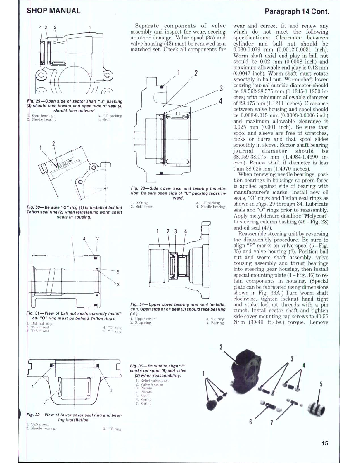
Fig.
29—Open side of sector shaft
"U"
packing
(3)
should face Inward and open side of seal (4)
should face outward.
1.
Gear housing 3. "I!" packing
2.
Needle bearing 4. Seal
Fig.
30—Be sure
"O"
ring (1)
is installed behind
Teflon
seai
ring (2)
when reinstailing worm shaft
seals in housing.
Fig. 31—View of baii nut seais correctly instail-
ed.
"O"
ring must be behind Tefion rings.
1.
Ball nut assy.
2.
Teflon seal ' 4. "0" ring
3.
Teflon seal 5. "()" ring
Separate components of valve
assembly and inspect for wear, scoring
or other damage. Valve spool (35) and
valve housing (48) must be renewed as a
matched set. Check all components for
Fig. 33—Side cover seai and bearing Installation.
Be sure open side of
"U"
packing faces
in-
ward.
3.
"IJ" packing
4.
Needle bearing
1.
"O'Ving
2.
Side cover
1
2
3
4
ifi
1!
J
Fig. 34—Upper cover bearing and seal installa-
tion.
Open side of oii seai
(3)
shouid face bearing
(4).
1.
nppor cover 3. "O" ring
2.
Snap ring 4. Bearing
wear and correct fit and renew any
which do not meet the following
specifications: Clearance between
cylinder and ball nut should be
0.030-0.079 mm (0.0012-0.0031 inch).
Worm shaft axial end play in ball nut
should be 0.02 mm (0.0008 inch) and
maximum allowable end play is 0.12 mm
(0.0047 inch). Worm shaft must rotate
smoothly in ball nut. Worm shaft lower
bearing journal outside diameter should
be 28.562-28.575 mm (1.1245-1.1250 inches) with minimum allowable diameter
of 28.475 mm (1.1211 inches). Clearance
between valve housing and spool should
be 0.008-0.015 mm (0.0003-0.0006 inch)
and maximum allowable clearance is
0.025 mm (0.001 inch). Be sure that
spool and sleeve are free of scratches,
nicks or burrs and that spool slides
smoothly in sleeve. Sector shaft bearing
journal dia m eter should be
38.059-38.075 mm (1.4984-1.4990 inches).
Renew shaft if diameter is less
than 38.025 mm (1.4970 inches).
When renewing needle bearings, position bearings in housings so press force
is applied against side of bearing with
manufacturer's marks. Install new oil
seals,
"0" rings and Teflon seal rings as
shown in Figs. 29 through 34. Lubricate
seals and "0" rings prior to reassembly.
Apply molybdenum disulfide "Molycoat"
to steering column bushing(46-Fig. 28)
and oil seal (47).
Reassemble steering unit by reversing
the disassembly procedure. Be sure to
align "P" marks on valve spool (5-Fig.
35) and valve housing (2). Position ball
nut and worm shaft assembly, valve
housing assembly and thrust bearings
into steering gear housing, then install
special mounting plate
(1 - Fig.
36) t o re-
tain components in housing. (Special
plate can be fabricated using dimensions
shown in Fig. 36A.) Turn worm shaft
clockwise, tighten locknut hand tight
and stake locknut threads with a pin
punch. Install sector shaft and tighten
side cover mounting cap screws to 40-55
N-m (30-40 ft.-lbs.) torque. Remove
Fig.
32—View of iower cover seai
ring
and bear-
ing installation.
1.
Teflnn sea!
2.
Needle bearing :i. "O" ring
Fig.
35—Be sure to aiign
"P"
marks on spool
(5)
and valve
(2) when reassembiing.
1.
Relief valve assy.
2.
Valve housing
3.
F^istons
4.
F^i.stons
5.
Spool
6. Spring
7.
Spring
6
7
15
Paragraphs 15-17
KUBOTA
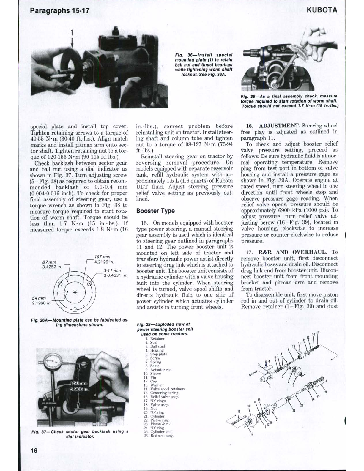
Fig. 36—Install speciai
mounting plate (1) to retain
ball nut and thrust bearings
while tightening worm shaft
tocknut See Fig. 36A.
Fig, 38—As a finai assembly check, measure
torque required to start rotation of worm shaft
Torque should not exceed 1.7 N-m (15 In.-lbs.)
special plate and install top cover.
Tighten retaining screws to a torque of
40-55 N-m (30-40 ft.-lbs.). Align match
marks and install pitman arm onto sector shaft. Tighten retaining nut to a torque of 120-155 N-m (90-115 ft.-lbs.).
Check backlash between sector gear
and ball nut using a dial indicator as
shown in Fig. 37. Turn adjusting screw
(5-Fig. 28) as required to obtain recommended backlash of 0.1-0.4 mm
(0.004-0.016 inch). To check for proper
final assembly of steering gear, use a
torque wrench as shown in Fig. 38 to
measure torque required to start rotation of worm shaft. Torque should be
less than 1.7 N-m (15 in.-lbs.). If
measured torque exceeds 1.8 N-m (16
Ftg. 36A—Mounting plate can be fabricated us-
ing dimensions shown.
37—Check sector gear backlash using a
dtat Indicator.
in.-lbs.),
c orrect problem before
reinstalling unit on tractor. Install steering shaft and column tube and tighten
nut to a torque of 98-127 N-m (75-94
ft.-lbs.).
Reinstall steering gear on tractor by
reversing removal procedure. On
models equipped with separate reservoir
tank, refill hydraulic system with ap-
proximately 1.5 L (1.6 quarts) of Kubota
UDT fluid. Adjust steering pressure
relief valve setting as previously out-
lined.
Booster Type
15.
On models equipped with booster
type power steering, a manual steering
gear assembly is used which is identical
to steering gear outlined in paragraphs
11 and 12. The power booster unit is
mounted on left side of tractor and
transfers hydraulic power assist directly
to steering drag link which is attached to
booster unit. The booster unit consists of
a hydraulic cylinder with a valve housing
built into the cylinder. When steering
wheel is turned, valve spool shifts and
directs hydraulic fluid to one side of
power cylinder which actuates cylinder
and assists in turning front wheels.
Fig. 39—Exploded view of
power steering booster unit
used on some tractors.
1.
Retainer
2.
Seal
3.
Ball stud
4.
Housing
5.
Stop plate
6. Screw
7.
Spring
8. Seats
9. Actuator rod
10.
Sleeve
11.
Pin
12.
Cap
13.
Washer
14.
Valve spool retainers
15.
Centering spring
16.
Reliefvalve assy.
17.
"O" rings
18.
Valve assy.
19.
Nut
20.
"0" ring
. 21. Cylinder
22.
Piston ring
23.
Piston & rod
24.
"0" ring
25.
Cylinder end
26.
Rod seal assy.
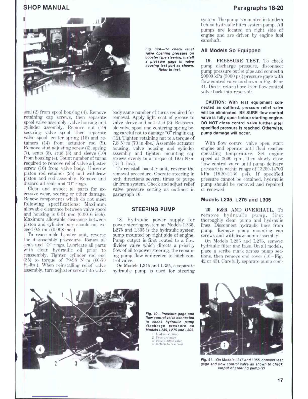
16.
ADJUSTMENT. Steering wheel
free play is adjusted as outlined in
paragraph 11.
To check and adjust booster relief
valve pressure setting, proceed as
follows: Be sure hydraulic fluid is at normal operating temperature. Remove
plug from test port in bottom of valve
housing and install a pressure gage as
shown in Fig. 39A. Operate engine at
rated speed, turn steering wheel in one
direction until front wheels stop and
observe pressure gage reading. When
relief valve opens, pressure should be
approximately 6900 kPa (1000 psi). To
adjust pressure, turn relief valve adjusting screw (16-F ig. 39), located in
valve housing, clockwise to increase
pressure or counter-clockwise to reduce
pressure.
17.
R&R AND OVERHAUL. To
remove booster unit, first disconnect
hydraulic hoses and drain oil. Disconnect
drag link end from booster unit. Disconnect booster unit from front mounting
bracket and pitman arm and remove
from tractor.
To disassemble unit, first move piston
rod in and out of cylinder to drain oil.
Remove retainer ( 1-Fig. 39) and dust
16
SHOP MANUAL
I
seal (2) from spool housing (4). Remove
retaining cap screws, then separate
spool valve assembly, valve housing and
cylinder assembly. Remove nut (19)
securing valve spool, then separate
valve spool, center spring (15) and retainers (14) from actuator rod (9).
Remove stud adjusting screw (6), spring
(7),
seats (8), stud (3) and sleeve (10)
from housing
(4).
Count number of turns
required to remove relief valve adjuster
screw (16) from valve body. Unscrew
piston rod retainer (25) and withdraw
piston and rod assembly. Remove and
discard all seals and "0" rings.
Clean and inspect all parts for excessive wear, scoring or other damage.
Renew components which do not meet
following specifications: Maximum
allowable clearance between valve spool
and housing is 0.04 mm (0.0016 inch).
Maximum allowable clearance between
piston and cylinder bore should not exceed 0.2 mm (0.008 inch).
To reassemble booster unit, reverse
the disassembly procedure. Renew all
seals and "0" rings. Lubricate all parts
with clean hydraulic oil prior to
reassembly. Tighten cylinder rod end
(25) to torque of 79-98 N-m (60-70
ft.-lbs.).
When reinstalling relief valve
assembly, turn adjuster screw into valve
Fig. 39A—TO check relief
vaive opening pressure on
booster type
steering^
Install
a pressure gage in valve
housing test port as shown.
Refer to text
body same number of turns required for
removal. Apply light coat of grease to
valve sleeve and ball stud (3). Reassemble valve spool and centering spring being careful not to damage "0" ring in cap
(12).
Tighten retaining nut to a torque of
7.8 N-m (70 in.-lbs.) Assemble actuator
housing, valve housing and cylinder
assembly and tighten mounting cap
screws evenly to a torque of 19.6 N-m
(15 ft.-lbs.).
To reinstall booster unit, reverse the
removal procedure. Operate steering in
both directions several times to purge
air from system. Check and adjust relief
valve pressure setting as outlined in
paragraph 16.
STEERING PUMP
18.
Hydraulic power supply for
power steering system on Models L235,
L275 and L305 is the hydraulic system
pump mounted on right side of engine.
Pump output is first routed to a flow
divider valve which directs a priority
flow of
oil
to power steering, the remaining pump flow is directed to hitch control valve.
On Models L345 and L355, a separate
hydraulic pump is used for steering
Paragraphs 18-20
system. The pump is mounted in tandem
behind hydraulic hitch system pump. All
pumps are located on right side of
engine and are driven by engine fuel
camshaft.
All Models So Equipped
19.
PRESSURE TEST. To check
pump discharge pressure, disconnect
pump pressure outlet pipe and connect a
20000 kPa (3000 psi) pressure gage with
flow control valve as shown in Fig. 40 or
41.
Direct return hose from flow control
valve back into reservoir.
CAUTION:
With test equipment connected as outlined, pressure reiief vaive
wiil be eiiminated. BE SURE fiow controi
vaive is fuiiy open before starting engine.
DO NOT ciose controi vaive further after
specified pressure is reached. Otherwise,
pump damage wiii occur.
With flow control valve open, start
engine and operate until fluid reaches
operating temperature. Set engine
speed at 2600 rpm., then slowly close
flow control valve until pump delivery
pressure is within range of 13250-14700
kPa (1920-2130 psi). If specified
pressure cannot be obtained, hydraulic
pump should be removed and repaired
or renewed.
Models L235, L275 and L305
20.
R&R AND OVERHAUL. To
remove hyd rau lic p ump , fir st
thoroughly clean pump and hydraulic
lines.
Disconnect hydraulic lines from
pump. Remove pump mounting cap
screws and withdraw pump assembly.
On Models L235 and L275, remove
hydraulic filter and base. On all models,
place a scribe mark across pump sections,
then remove end cover (10-Fig.
42 or 43). Carefully separate pump com-
Fig. 40—Pressure gage and
flow control valve connected
to check hydraulic pump
discharge pressure on
Modeis L235, L275 and L305.
1.
H ydraul ic pu mp
2.
I*r(.'ssure gag e
'A. F^low co ntrol val ve
4.
R etur n to res ervoir
Fig. 41—On Models L345 and L355, connect test
gage and fiow control vatve as shown to check
output of steering pump (2).
17
Paragraph 21
KUBOTA
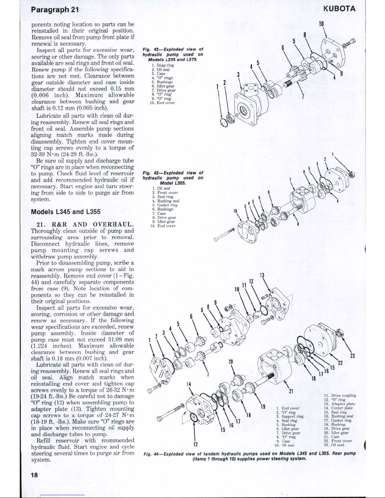
ponents noting location so parts can be
reinstalled in their original position.
Remove oil seal from pump front plate if
renewal is necessary.
Inspect all parts for excessive wear,
scoring or other damage. The only parts
available are seal rings and front oil seal.
Renew pump if the following specifications are not met. Clearance between
gear outside diameter and case inside
diameter should not exceed 0.15 mm
(0.006 inch). Maximum allowable
clearance between bushing and gear
shaft is 0.12 mm (0.005 inch).
Lubricate all parts with clean oil during reassembly. Renew all seal rings and
front oil seal. Assemble pump sections
aligning match marks made during
disassembly. Tighten end cover mounting cap screws evenly to a torque of
32-39 N-m (24-29 ft.-lbs.).
Be sure oil supply and discharge tube
"0"
rings are in place when reconnecting
to pump. Check fluid level of reservoir
and add recommended hydraulic oil if
necessary. Start engine and turn steering from side to side to purge air from
system.
Models L345 and L355
21.
R&R AND OVERH AUL .
Thoroughly clean outside of pump and
surrounding area prior to removal.
Disconnect hydraulic lines, remove
pump mounting cap screws and
withdraw pump assembly.
Prior to disassembling pump, scribe a
mark across pump sections to aid in
reassembly. Remove end cover (1- Fig.
44) and carefully separate components
from case (9). Note location of components so they can be reinstalled in
their original positions.
Inspect all parts for excessive wear,
scoring, corrosion or other damage and
renew as necessary. If the following
wear specifications are exceeded, renew
pump assembly. Inside diameter of
pump case must not exceed 31.09 mm
(1.224 inches). Maximum allowable
clearance between bushing and gear
shaft is 0.18 mm (0.007 inch).
Lubricate all parts with clean oil during reassembly. Renew all seal rings and
oil seal. Align match marks when
reinstalling end cover and tighten cap
screws evenly to a torque of 26-32
N • m
(19-24 ft.-lbs.) Be careful not to damage
"0"
ring (12) when assembling pump to
adapter plate (13). Tighten mounting
cap screws to a torque of 24-27 N-m
(18-19 ft. -lbs.). Make sure "0" rings are
in place when reconnecting oil supply
and discharge tubes to pump.
Refill reservoir with rcommended
hydraulic fluid. Start engine and cycle
steering several times to purge air from
system.
Fig. 42—Expioded view of
hydraulic pump used on
Models 1235 and L275.
1.
Snap ring
2.
Oil seal
3.
Case
4.
"0" rings
5.
Bushings >
6. Idler gear
7.
Drive gear
8. "0" ring'
9. "O"ring
10.
End cover
Ftg. 43—Exploded vtew of
hydraulic pump used on
Model L305.
1.
Oil seal
2.
Front cover
3.
Seal ring
4.
Bushing seal
5.
Gasket ring
6. Bushings
7.
Case
8. Drive gear
9. Idler gear
10.
End cover
IS
15
16
1.
End cover
2.
"0" ring
3.
Support ring
4.
Seal ring
5.
Bushing
6. Idler gear
7.
Drive gear
8. "0" ring
9. Case
10.
Oil seal
11.
Drive coupling
12.
"0" ring
13.
Adapter plate
14.
Center plate
15.
Seal ring
16.
Bushing seal
17.
Gasket ring
18.
Bushing
19.
Drive gear
20.
Idler gear
21.
Case
22.
Front cover
23.
Oil seal
Fig. 44—Expioded vtew of tandem hydrauiic pumps used on Models L345 and L355. Rear pump
(Items 1 through 10) supplies power steering system.
18
SHOP MANUAL
Paragraphs 22-24
ENGINE AND COMPONENTS
R&R ENGINE
All Models
22.
To remove engine and clutch as a
unit, first drain cooling system, engine
oil,
transmission oil, power steering
reservoir (if equipped) and front wheel
drive differential housing (if equipped).
Remove front axle assembly as follows:
Remove hood, side panels and upper
support rail (if equipped), muffler and
battery. Disconnect radiator hoses and
air cleaner hose. Disconnect drag link
end using a suitable puller. On front
wheel drive models, unbolt and remove
drive shaft. On all models, support
tractor under clutch housing and support front end unit with a suitable hoist
or splitting stand. Remove front axle
bracket mounting cap screws, then roll
front end away from engine. To
separate engine from clutch housing,
disconnect wiring to engine as necessary
Disconnect fuel supply line, fuel return
line and hydraulic hoses and tubes.
Disconnect throttle control linkage,
engine stop rod (if equipped), hourmeter cable and decompression cable.
Support engine with a suitable hoist,
remove cap screws securing flywheel
housing to clutch housing and separate
engine from transmission.
To reinstall engine, reverse the
removal procedure. Tighten clutch housing mounting cap screws to a torque of
49-54 N-m (36-41 ft.-lbs.). Tighten front
axle bracket fasteners to the following
torques: MIO nut to 61-71 N-m (45-50
ft.-lbs.),
MIO bolt to 48-56 N-m (;-i6-41
ft.-lbs.) and M12 nut or bolt ot 78-90
N-m (58-66 ft.-lbs.).
CYLINDER HEAD
All Models
23.
To remove cylinder head, first
drain cooling system and disconnect battery cables. Remove hood, muffler and
side covers (if equipped). Remove upper
radiator hose, coolant return hose and
intake manifold hose. Disconnect decompressor control cable. Remove injection
lines and nozzle assemblies and cap all
exposed fittings to prevent entry of dirt.
Remove alternator adjusting bracket.
Remove valve lever cover. Remove
valve levers an(i shaft assembly and
withdraw push ro(is. Remove cap screws
and nuts securing cylinder head and lift
head off cylinder block.
One or more shims may he installed
between gasket and cylinder head to ad-
just clearance between cylinder head
and piston tops. Identify shims when
cylinder head is removed, then install an
equal number of shims when head is
reinstalled. To check piston to head
clearance, insert a soft lead wire
through injection nozzle holder hole.
Rotate crankshaft by hand until lead
wire is fiattened by piston top. Measure
thickness of fiattened wire to determine
top clearance which should be 0.7-0.9
mm (0.028-0.035 inch).
NOTE:
Because of minimum amount of
clearance that exists between vaives and
piston tops, ioosen vaive iever adjusting
screws before reinstailing vaive ievers
and shaft assembiy to prevent possibie
damage to vaives.
Check cylinder head surface for
distortion using a straightedge and
feeler gage. If a 0.05 mm (0.002 inch)
feeler gage can be inserted between
cylinder head and straightedge, head
surface should be refaced with a surface
grinder. A maximum of 0.5 mm (0.020
inch) of material may be removed to true
cylinder head surface. Refer to
paragraph 25 for valve head recession
specifications.
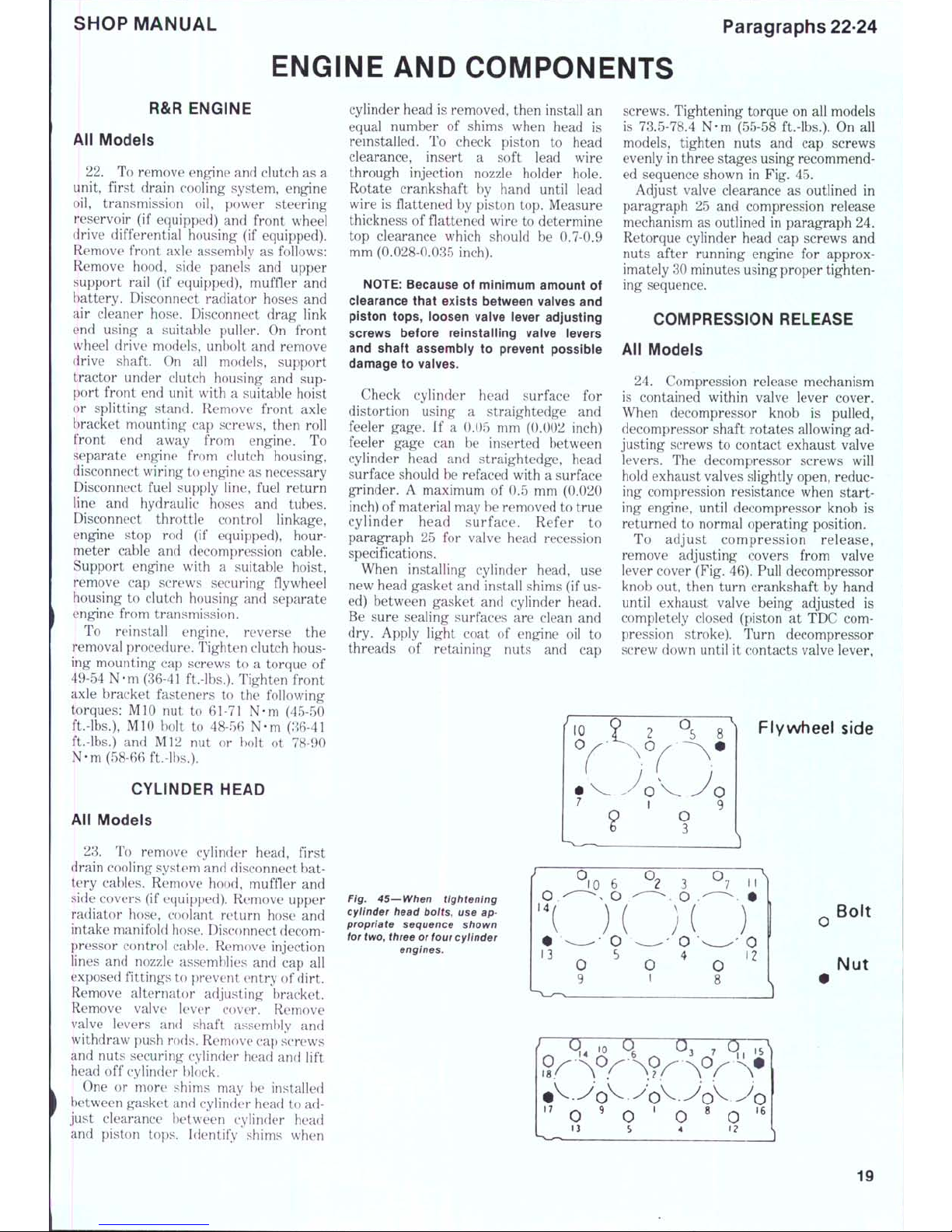
When installing cylinder head, use
new head gasket and install shims (if used) between gasket and cylinder head.
Be sure sealing surfaces are clean and
dry. Apply light coat of engine oil to
threads of retaining nuts and cap
screws. Tightening torque on all models
is 73.5-78.4 N-m (55-58 ft.-lbs.). On all
models, tighten nuts and cap screws
evenly in three stages using recommended sequence shown in Fig. 45.
Adjust valve clearance as outlined in
paragraph 25 and compression release
mechanism as outlined in paragraph 24.
Retorque cylinder head cap screws and
nuts after running engine for approximately 30 minutes using proper tightening sequence.
COMPRESSION RELEASE
All Models
24.
Compression release mechanism
is contained within valve lever cover.
When decompressor knob is pulled,
decompressor shaft rotates allowing ad-
justing screws to contact exhaust valve
levers. The decompressor screws will
hold exhaust valves slightly open, reducing compression resistance when starting engine, until decompressor knob is
returned to normal operating position.
To adjust compression release,
remove adjusting covers from valve
lever cover (Fig. 46). Pull decompressor
knob out, then turn crankshaft by hand
until exhaust valve being adjusted is
completely closed (piston at TDC compression stroke). Turn decompressor
screw down until it contacts valve lever.
Flywheel side
Fig. 45—When tightening
cyiinder head boits, use appropriate sequence shown
for two, three or four cylinder
engines.
Bolt
Nut
19

Paragraphs 25-26
KUBOTA
Compression release
position
Ftg. 46—Cross-sectional
view of decompressor mechanism and adjustment point
0.750 to 1.125mm
0.0295 to 0.0443 in.
then turn screw down an additional 1 to
IV2 turns to obtain specified valve opening of 0.750-1.125 mm (0.030-0.044
inch).
Tighten locknut while holding ad-
justing screw. Repeat adjustment pro-
cedure for remainder of exhaust valves.
NOTE:
After adjustment is completed,
puil knob out and turn cranlcshaft by hand
to make certain valves do not contact
piston tops.
VALVES AND SEATS
All Models
25.
Intake and exhaust valves are
not interchangeable. All valves seat
directly in cylinder head. Valve face and
seat angles are 45 degrees for all valves.
Recommended valve seat width is 2.1
mm (0.080 inch). Valve stem diameter is
7.960-7.975 mm (0.3134-0.3140 inches)
t
for all valves. Face of valves should be
recessed
1.1-1.3
mm (0.043-0.051 inch)
below surface of cylinder head. Maximum allowable recession is 1.6 mm
(0.063 inch).
Whenever valves are renewed or
reseated, be sure to adjust compression
release mechanism as previously outlined.
Valve clearance, gap between valve
stem end and valve lever, is adjusted
with engine cold on all models. Recommended g ap is 0.18-0.22 mm
(0.007-0.009 inch) for both intake and
exhaust on all models.
CAUTION:
Due to close ciearance between valves a pistons, severe damage
can resuit from inserting feeler gage be-
tween vaive stem and vaive iever with
engine running. DO NOT attempt to adjust
vaive clearance with engine running.
To adjust valve clearance, proceed as
follows: Loosen valve lever adjusting
screw locknuts. Rotate crankshaft by
hand to position number one piston at
top dead center of compression stroke.
Using a feeler gage to measure
clearance, adjust valves for number one
cylinder. Adjust remaining valves in se-
quence of firing order after positioning
each piston at top dead center of compression stroke.
VALVE GUIDES
All Models
26.
Intake and exhaust valve guides
are semi-finished and must be reamed
after installation in cylinder head. Intake and exhaust valve guides are not in-
terchangeable as exhaust guide is
equipped with a "carbon scraper" at
lower end of guide (Fig. 47). Press new
guides into cylinder head until guide
shoulder is seated against surface of
head. All models are equipped with cuptype stem seals which fit over stem end
of valve guide.
Desired operating clearance of valve
stem in guide is 0.04-0.07 mm
(0.0016-0.0028 inch). Maximum
14
Fig. 48—Exploded vtew of
valves and valve lever
assembly.
1.
Intake valve
2.
Exhaust valve
3.
Valve stem seal
4.
Spring
5.
Retainer
6. Keepers
7.
Cap
8. Snap ring
9. Washer
10.
Bushing
11.
Adjusting screw
12.
Spring
13.
Valve lever
14.
Bracket
15.
Shaft
10
Fig. 47—Exhaust valve guide is equipped with a
"carbon scraper" (C) and is not interchangeable
with Intake guide. Note scraper area when
measuring inside diameter
(A
and B) of guides.
20
 Loading...