

Page 1
GB
MINI EXCAVATOR
MODELS
KX61-3
KX71-3
OPERATING INSTRUCTIONS
RG248-8135-9 - Original - 05/2015
Page 2

Dear valued customer,
please fill in the form below. Your information will help us to help you.
Type:
YOC:
Serial #:
Shipment date:
Please contact your KUBOTA dealer for any additional information or troubleshooting procedures not mentioned in these operating ins tr uct ions.
We also point out that the c ontents of thes e operatin g ins tructions are not par t of a n earlier ex isti ng agreem ent,
promise or legal relations hip or am end these. All r esponsib ilities aris e of the r espective s ales contr act contai ning the complete and exclusively valid contractual warranty. See the "Duties, liability and warranty" section
(page 12). This documentation does neither extend nor restrict the contractual warranty.
KUBOTA Baumas chinen GmbH reserves its right to change the inform ation contained in this document with
respect to future tech nical development without a ltering the basic characteristic s of the excavators descr ibed
herein and without amending this document.
Distribution and reproduction of this documentation and disclosure of its content are not allowed unless expressly approved by the manufacturer. Violators of the above terms are liable for compensation for damages.
2
Page 3

Tables
Table of contents
Abbreviations ...................................................................................................................................................... 8
General symbols................................................................................................................................................. 9
GENERAL INFORMATION ............................................................................................................... 10
Foreword .......................................................................................................................................................... 10
EC declaration of conformity ............................................................................................................................ 10
Date of issue of the operating instructions ....................................................................................................... 11
Operating personnel ......................................................................................................................................... 11
Location of the operating in s truc tions .............................................................................................................. 11
Spare parts ....................................................................................................................................................... 11
SAFETY RULES ............................................................................................................................... 12
Basic safety instructions ................................................................................................................................... 12
Duties, liability and warranty ............................................................................................................................. 12
Safety symbols ................................................................................................................................................. 14
Approved use ................................................................................................................................................... 15
Unapproved use ............................................................................................................................................... 15
Special duties of the owner .............................................................................................................................. 15
Noise emission and vibrat ion ........................................................................................................................... 16
Noise emission ................................................................................................................................................. 16
Vibrations .......................................................................................................................................................... 16
Safety labels on the excavator ......................................................................................................................... 17
Safety devices .................................................................................................................................................. 24
Locking the controls .................................................................................................................................... 24
Engine stop knob ......................................................................................................................................... 24
Roll-over protection (ROPS) ....................................................................................................................... 25
Emergency hammer .................................................................................................................................... 25
Hazards coming from the hydraulic system ..................................................................................................... 25
Fire protection................................................................................................................................................... 26
RECOVERY, LOADING AND TRANSPORT .................................................................................... 27
Safety rules for recovery .................................................................................................................................. 27
Safety rules for hoisting the excavator with a crane......................................................................................... 27
Safety rules for transport .................................................................................................................................. 27
Recovery .......................................................................................................................................................... 28
Hoisting the excavator with a crane ................................................................................................................. 28
Transport on a flat bed trailer ........................................................................................................................... 30
DESCRIPTION OF THE EXCAVATOR ............................................................................................. 32
Model overview................................................................................................................................................. 32
Model KX61-3 .............................................................................................................................................. 32
Model KX71-3 .............................................................................................................................................. 32
Dimensions ....................................................................................................................................................... 33
KX61-3 Dimensions ..................................................................................................................................... 33
KX71-3 Dimensions ..................................................................................................................................... 34
Specifications ................................................................................................................................................... 35
Identification of the excavator ........................................................................................................................... 36
Equipment ........................................................................................................................................................ 36
Standard equipment .................................................................................................................................... 36
ASSEMBLY AND FUNCTIONS ........................................................................................................ 37
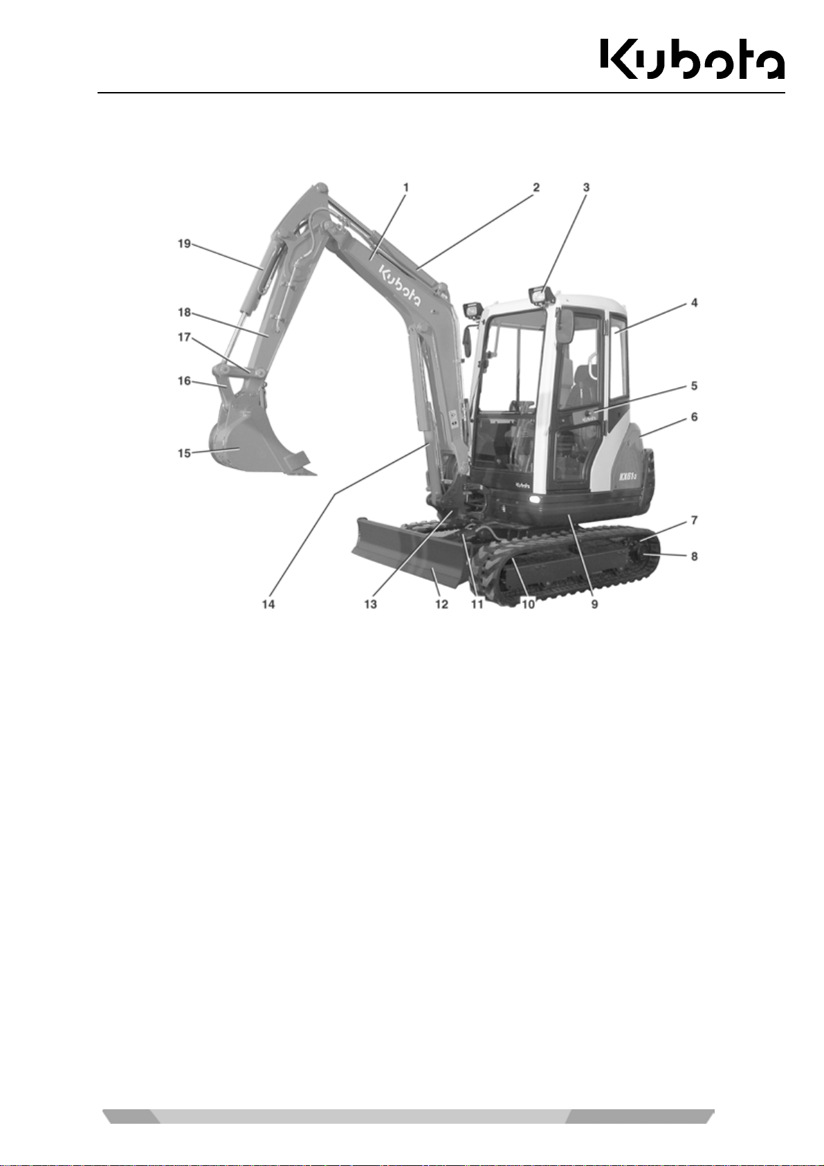
Component overview ........................................................................................................................................ 37
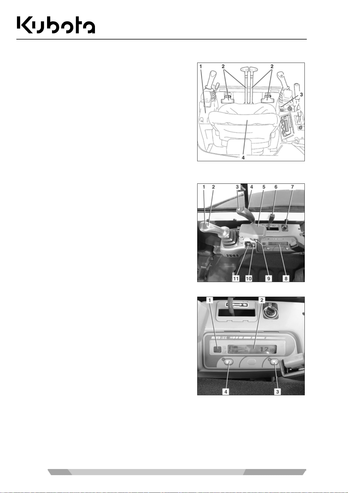
Operator's place ............................................................................................................................................... 38
3
Page 4

Right control console ...................................................................................................................................38
Description of the components of the right control console ...................................................................39
Displays and indicators - description ......................................................................................................39
Left control console ......................................................................................................................................40
Description of the components of the left control console ......................................................................40
Controls........................................................................................................................................................40
Description of the controls ......................................................................................................................41
Further components in the cab ....................................................................................................................42
Wiper/washer system .............................................................................................................................42
Interior lighting ........................................................................................................................................42
Fuse box .................................................................................................................................................42
Vehicle battery ........................................................................................................................................43
Tool compartment ...................................................................................................................................43
Fuel tank filler opening ...........................................................................................................................43
Engine compartment .........................................................................................................................................44
Hydraulic system ...............................................................................................................................................45
Tables
OPERAT ION ..................................................................................................................................... 46
Safety rules for operation ..................................................................................................................................46
Safety for children ........................................................................................................................................47
Guiding the operator ....................................................................................................................................47
Working in the vicinity of overhead power lines ..........................................................................................48
Working in the vicinity of underground power lines .....................................................................................48
Initial operation ..................................................................................................................................................49
Setting the display language .......................................................................................................................49
Running-in of the excavator .........................................................................................................................49
Special maintenance instructions ................................................................................................................49
Operating the excavator ...................................................................................................................................49
Pre-operational services ..............................................................................................................................49
Check the engine oil level.......................................................................................................................50
Checking the coolant leve l......................................................................................................................50
Checking the radiator and the oil cooler .................................................................................................50
Checking the V-belt ................................................................................................................................51
Checking the exhaust system for leaks ..................................................................................................51
Checking the oil level of the hydraulic system........................................................................................51
Checking the water separator of the fuel system ...................................................................................52
Lubrication ..............................................................................................................................................52
Checking the fuel level of the fuel tank ...................................................................................................53
Setting up the workplace .............................................................................................................................53
Getting on the excavator ........................................................................................................................54
Adjusting the operator's seat ..................................................................................................................54
Horizontal seat adjustment (seat stand-off) ......................................................................................54
Spring adjustment (operator's weight) ...............................................................................................54
Seat height adjustment (knee height)................................................................................................54
Backrest adjustment ..........................................................................................................................55
Seat belt ............................................................................................................................................55
Exterior mirror adjustment .................................................................................................................55
Safety instructions for starting the engine ...................................................................................................55
Starting the engine .......................................................................................................................................56
Stopping the engine .....................................................................................................................................57
Observation of the displays after starting and during operation ..................................................................57
Driving the excavator ...................................................................................................................................58
Driving .....................................................................................................................................................59
Turning....................................................................................................................................................60
During driving ....................................................................................................................................60
From a standing position ...................................................................................................................61
Turning on the spot............................................................................................................................61
Driving uphill and downhill ......................................................................................................................61
Notes for rubber crawler operation .........................................................................................................62
Making sharp turns ............................................................................................................................62
Protecting the crawler against salt ....................................................................................................62
4
Page 5

Tables
Operating the controls during excavation work ........................................................................................... 62
Notes for using wider and deeper buckets .................................................................................................. 63
Operating the dozer blade ..................................................................................................................... 63
Overview of control lever functions ........................................................................................................ 64
Operating the boom ............................................................................................................................... 64
Operating the arm .................................................................................................................................. 65
Operating the bucket .............................................................................................................................. 66
Swivelling the swivel frame .................................................................................................................... 66
Swinging the boom ................................................................................................................................. 67
Operating the auxiliary port ......................................................................................................................... 68
Return change valve .............................................................................................................................. 69
Pressure relief of the hydraulic system .................................................................................................. 69
Placing out of operation .................................................................................................................................... 70
Cab version only .................................................................................................................................... 70
Operating the wiper/washer system ................................................................................................................. 71
Switching on the windscreen wiper ............................................................................................................. 71
Switching on the washer system ................................................................................................................. 71
Operating the room light (cab version) ............................................................................................................. 72
Operating the rotary beacon (accessories) ...................................................................................................... 72
Operating the heater (cab version)................................................................................................................... 72
Opening and closing the cab door.................................................................................................................... 74
Opening the cab door from outside ............................................................................................................. 74
Closing the cab door ................................................................................................................................... 74
Opening the cab door from inside ............................................................................................................... 74
Opening and closing the windows .................................................................................................................... 75
Front window ............................................................................................................................................... 75
Side window ................................................................................................................................................ 76
Operating the working lights ............................................................................................................................. 76
Cold weather operation .................................................................................................................................... 77
Necessary preparations prior to the winter season ..................................................................................... 77
Operation during the winter season ............................................................................................................ 77
Jump-starting the excavator ............................................................................................................................. 78
Emergency stop functions ................................................................................................................................ 79
Manual engine stop ..................................................................................................................................... 79
Manual lowering of the front attachments ................................................................................................... 79
Filling up the washer system ............................................................................................................................ 79
Refuelling the excavator ................................................................................................................................... 80
Bleeding the fuel system .................................................................................................................................. 80
Replacing the fuses .......................................................................................................................................... 81
Fuse layout of the fuse box ......................................................................................................................... 82
Installing and uninstalling the operator's seat .................................................................................................. 82
Opening and closing the engine compartment cover ....................................................................................... 82
Opening and closing the side cover ................................................................................................................. 83
Removing and installing the right side panel .................................................................................................... 83
Replacing the bucket ........................................................................................................................................ 84
Anti-theft system ............................................................................................................................................... 84
Black (individual) key................................................................................................................................... 85
Red key (for registering) .............................................................................................................................. 85
The key system ........................................................................................................................................... 85
Registering a black key for the machine ..................................................................................................... 86
TROUBLESHOOTING ...................................................................................................................... 88
Safety rules for troubleshooting ........................................................................................................................ 88
Troubleshooting: Pre-operational services ....................................................................................................... 88
Troubleshooting: operation ............................................................................................................................... 89
Troubleshooting: Display indications ................................................................................................................ 90
5
Page 6

Tables
MAINTENA NCE ................................................................................................................... ............. 91
Safety rules for maintenance ............................................................................................................................91
Personnel requirements ....................................................................................................................................91
General maintenance chart: 50 to 500 hours of operation ...............................................................................92
General maintenance chart: 550 to 1000 hours of operation ...........................................................................93
Servicing maintenance chart: 50 to 500 hours of operation .............................................................................94
Servicing maintenance chart: 550 to 1000 hours of operation .........................................................................95
Cleaning the excavator .....................................................................................................................................96
Maintenance .....................................................................................................................................................96
Refilling the coolant .....................................................................................................................................96
Cleaning the radiator ...................................................................................................................................97
Checking and adjusting the V-belt tension ..................................................................................................97
Checking the coolant hoses ........................................................................................................................98
Replacing the engine oil and oil filter ...........................................................................................................98
Draining the engine oil ............................................................................................................................98
Replacing the oil filter .............................................................................................................................99
Filling the engine oil ................................................................................................................................99
Replacing the coolant ................................................................................................................................100
Checking and cleaning the air filter ...........................................................................................................101
Replacing the fuel filter ..............................................................................................................................102
Draining water from the fuel tank ...............................................................................................................103
Replacing the return filter in the hydraulic oil tank .....................................................................................103
Replacing the suction filter in the hydraulic oil tank ...................................................................................104
Draining and topping up hydraulic oil ........................................................................................................105
Draining the hydraulic oil ......................................................................................................................105
Filling the hydraulic oil ..........................................................................................................................106
Replacing the breather filter in the hydraulic oil tank .................................................................................106
Battery service ...........................................................................................................................................107
Checking the fluid level of the battery ..................................................................................................107
Charging the battery .............................................................................................................................108
Installing/uninstalling and replacing the battery....................................................................................109
Lubrication .................................................................................................................................................109
Greasing the swivel gear ......................................................................................................................109
Greasing the pitch bear ing ...................................................................................................................110
Checking and tensioning the crawler tension ............................................................................................110
Checking the crawler tension ...............................................................................................................111
Adjusting the crawler tension................................................................................................................111
Replace the drive unit oil ...........................................................................................................................112
Greasing the pilot valve linkage .................................................................................................................112
Checking the electric cables and connections ..........................................................................................112
Replacing the in-line filter ..........................................................................................................................113
Resetting the service period indicator .......................................................................................................113
Checking the bolted joints ...............................................................................................................................114
Tightening torque for screws .....................................................................................................................114
Tightening torque for hose clamps ............................................................................................................114
Tightening torque for hydraulic hoses .......................................................................................................114
Tightening torque for hydraulic pipes ........................................................................................................115
Tightening torque for hydraulic adapters ...................................................................................................115
Recommended lubricants ...............................................................................................................................116
Repair work on the machine ...........................................................................................................................117
SAFETY INSPECTION .................................................................................................................... 118
6
Page 7

Tables
TAKING OUT OF SERVICE AND STORAGE ................................................................................ 119
Safety rules for taking out of service and storage .......................................................................................... 119
Storage conditions .......................................................................................................................................... 119
Measures before taking out of service ........................................................................................................... 119
Measures during taking out of service ........................................................................................................... 119
Start-up after taking out of service ................................................................................................................. 120
LIFTING CAPACITY OF THE EXCAVATOR .................................................................................. 121
Constructive calculation of lifting capacity ...................................................................................................... 121
Lifting attachment ........................................................................................................................................... 122
Load suspension device ................................................................................................................................. 123
Max. lifting load during swivel operation is 360° ............................................................................................ 124
ACCESSOR IES .............................................................................................................................. 134
KUBOTA rotary beacon .................................................................................................................................. 134
KUBOTA arms ................................................................................................................................................ 134
KUBOTA pipe safet y valve ............................................................................................................................. 135
Note on the use ............................................................................................................................... 135
KUBOTA overload warning function............................................................................................................... 136
KUBOTA quick coupling systems and equipments ........................................................................................ 136
KUBOTA bucket accessories ......................................................................................................................... 136
7
Page 8

Tables
Abbreviations
1/min revolutions per minute ISO International Organization for Standardi% percent zation
° degrees kg Kilogramme
°C degree Celsius km/h Kilometre per hour
A Ampere kN Kilonewton
acc. according kV Kilovolt
API American Petroleum Institute kW Kilowatt
approx. approximately L Litre
ASTM American Society for Testing and L/min Litres per minute
Materials LpA Sound pressure level operator's place
bar bar LwA Measured sound power level
CECE Committee for European Construction m Metre
Equipment m/s² Metre per square second
CO2 carbon dioxide m³ Cubic metre
dB Decibel max. Maximum
DIN Deutsches Institut für Normung (German mm Millimetre
Institute for Standards) MPa Megapascal
e.g. For example N Newton
EMC Electromagnetic compatibility resp. Respectively
EN European standard s Second
GL Ground level t Ton
incl. including V Volt
8
Page 9

Tables
General symbols
Warning light
Fuel display
Engine oil display
Charge display
Glow display
Hydraulic oil
Travel speed
Low speed
Swivel boom (left)
Swivel boom (right)
Dozer blade up
Dozer blade down
Control lever directi on
Control lever directi on
Rotary beacon indicator on/of f
Display sel ector switch
Forward travel
Backward travel
Raise boom
Lower boom
Arm dump
Arm crowd
Bucket crowd
Bucket dump
Auxiliary port switch
Working light button
9
Page 10
General information
GENERAL INFORMATION
Foreword
These operating inst ructions apply only to the K UBOTA excavator models KX61-3 and KX71-3 which
comply with the declaration of conformity stated below (page 10).
Safety instructions, the rules and reg ulations for the use of excavators given in these operating instructions
apply to the excavators mentioned in this documentation.
It is the responsibility of the owner(s):
• to ensure local, regional and national regulations are observed,
• to observe the bodies of rules (laws, regulations, guidelines, etc) stated in the operating instructions to
ensure safe handling of the equipment,
• to ensure that the operating instruc tions are al ways availa ble for the oper ating pers onnel and the i nforma-
tion such as notes, warnings and safety rules and regulations are followed in all points.
The data in the oper ating ins tructions app ly for all m odels. An y differ ences are highl ighted (e.g. cab versi on or
KX61-3, KX71-3).
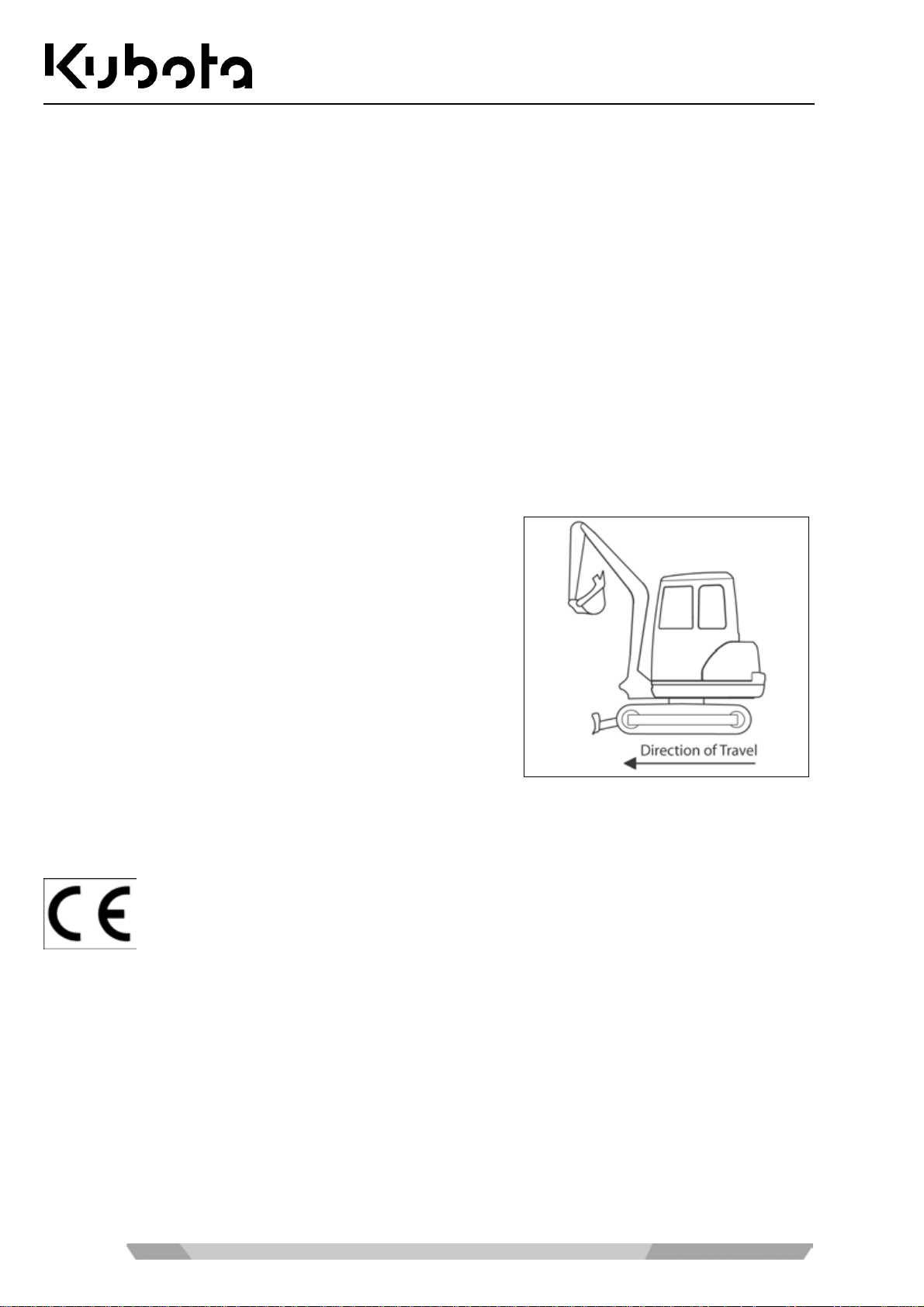
The terms "fr ont" and "dire ction of tr avel" ref er to the view of the
operator when seated on the operator's seat. Forwar d direction
of travel means that the dozer is at the front when driving forwards as shown in the figure.
The symbols for operating and safety instructions are listed under "Safety Symbols" (page 14).
EC declaration of conformity
With the EC declaration of conformity, KUBOTA Ba umaschinen Gm bH certifies that the exc avator is in conformity with the va lid s tandards and regu lat io ns at the time of marketin g. T he CE
conformity marking is located on the type plate and indicates compliance with the regulations.
Should the EC declaration of conformity get lost, please contact your KUBOTA dealer.
If the excavator is modified or retrofitted without the approval of th e manufacturer, the safet y of
the excavator may be affected, thus invalidating the EC declaration of conformity.
The EC declaration of conf ormity is attached to the operating instructions f or delivery of the
excavator.
Keep the EC declaration of conform ity in a safe place and s how it, if reques ted, to the responsible authorities.
10
Page 11

General information
Date of issue of the operating instructions
The date of issue of the operating instructions is printed on the bottom right of the front page of the book.
Operating personnel
The duties of personnel with respect to operation, ser vicing, repairs and safety inspec tions must be set forth
clearly by the owner.
Personnel in traini ng are allowed to work on or with the ex cava tor o nly under the supervisio n of a n ex p erie nc e d
operator.
Operator
According to industrial s afety regulations, onl y persons who were instructed in th e operation of the excavator,
who have proven their ab ility to the owner (employer) and who can be expected to perform their duties in a
reliable way are allowed to operate the excavator independently.
Only trained and instructed personne l ar e allo wed to wor k on or with the excavato r .
Only instructed personnel are allowed to start the excavator and operate the controls.
Trained personnel
Trained personne l are skilled p ersons with a tec hnical qual ification who ar e able to determ ine damages to the
excavator and perform repairs in their area of qualification (e.g. hydraulic or electrical engineering).
Qualified personnel
Based on their t echnical training and exp erience i n the ir field, q ualified pers onnel shoul d have s uffic ient know ledge about the technolog y used in this machine and be familiar with the ap plicabl e nationa l work safet y regulations, accident prev ention regulations and the generally accepted tec hnical rules so that the y can assess the
safe condition of the machine.
Location of the operating instructions
The operating instruc tions must always be kept on the excava tor. If the operating instructions ha ve become
illegible due to continuous use, the owner (operator) must order a replacement from the manufacturer.
Spare parts
Genuine spare parts can b e or dered from KUBOTA dealers b y stating th e model and the serial # of the exc avator.
The item numbers for the spare parts are indicated in the parts catalogue.
11
Page 12

Safety rules
SAFETY RULES
Basic safety instructions
• The EC machine utilization directive (2009/104/EC) dated 16/09/2009 applies for the operation of the
aforementioned excavat or .
• The information in these operating instructions applies for maintenance and repairs.
• National rules and regulations apply where applicable.
Duties, liability and warranty
A basic requisite for the safe handling and problem-free operation of the excavator is the knowledge of the
safety instructions and safety regulations.
These operating i nstructio ns, in particular the saf ety in structions , mus t be follo wed b y all pers ons work ing near
or with the excavator. Above and beyond t his, the saf et y rules and reg ulations applica ble for the s ite m ust also
be observed.
Hazards occurring during the handling of the excavator:
• The excavators are m anufactured according to the state of technology and the recognized s afety rules.
Nevertheless, danger to t he lif e and l im bs of the operator or a th ird p arty, or dam age to the excavat or or to
other property can occur. The excavator(s) may only be used
→ for the approved use and
→ in a completely safe operating state.
Malfunctions which can reduce safety must be repaired immediately.
Warranty and liability
The scope, period and f orm of the warranty are se t forth in the sales and de livery conditions of the manufacturer. The operating instructions valid at the tim e of delivery shall be the basis for any warranty cla ims arising
from errors in the va lid op erating ins truc tions (page 11 ). T he follo wing ap plies abo ve and be yond the sales a nd
delivery conditions: No warranty or liability shall be assumed for personnel and property damages resulting
from one or more of the following reasons:
• unapproved use of the excavator,
• improper starting, operation and maintenance of the excavator,
• operation of th e excavator with defect ive safety devices or im properly installed or n on-operational safety
and protective devices,
• ignorance or non-observance of these operating instructions,
• insufficiently qualified or insufficiently instructed operating personnel,
• improperly performed repairs,
• unauthorised engineering changes to the excavator,
• poor surveillance of machine parts subject to wear,
• catastrophes caused by the effect of foreign objects or an act of God.
12
Page 13

Safety rules
The owner must ensure at his own responsibility that
• the safety rules are observed (page 12),
• unapproved use and unauthorised operation (page 15) are excluded and
• the approved use (page 15) is ensured and the excavator is operate d in accordance with the contractual
conditions of use.
13
Page 14
Safety symbols
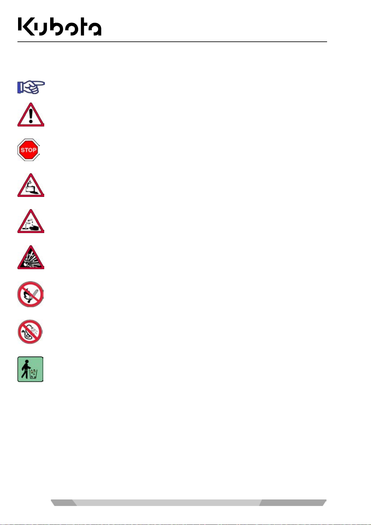
The following terms and hazard symbols are used in these operating instructions:
Identifies importan t operating procedure inf ormation which may not be immediately evid ent to
the operator.
Identifies operating procedures which must be followed exactly to prevent damage to the
excavator or other property.
Identifies operating procedures which must be followed exactly to prevent danger to persons.
Identifies possible hazards in the handling of batteries.
Safety rules
Identifies possible hazards from caustic materials (battery acid).
Identifies possible hazards from explosive materials.
Prohibits the use of fire, ignition sources, and smoking.
Prohibits the spraying of water.
Identifies operating procedures for the proper disposal and storage of ensuing waste materials.
14
Page 15

Safety rules
Approved use
The excavators specified in this operating instructions may only be used to loosen the ground, excavating,
picking up, transpor ti ng an d dumping soils, rock s and other materials, for work with th e d o zer or with a br eak er .
The load may be transported largely without driving the excavator. Do not exceed the maximum lifting capacity.
Approved use also includes :
• observation of all notes in these operating instructions,
• regular servicing,
• regular safety inspections.
Unapproved use
Any improper use – i. e. any deviation from the informatio n in the "Approved use" section ( page 15) of thes e
operating instructio ns – is cons idered an unap proved u se. This als o applies to the non-observanc e of the sta ndards and guidelines listed in these operating instructions.
Hazards can occur in case of improper use. Such improper uses include:
• using the excavator to lift loads withou t suit ab le loa d lift ing attachments,
• using the excavator in contaminated environments,
• using the excavator in closed rooms without insufficient ventilation;
• using the excavator under conditions of extreme temperatures (extreme heat or cold),
• using the excavator for underground works,
• using the excavator to transport persons in the bucket, and
• using the excavator for dem olition with out the corr esp onding equipment.
Special duties of the owner
Owner of the excava tor in the sense of these operatin g instructions is any perso n or company whic h uses the
excavator itself or on whose order it is us ed. In special cases (e.g. leas i ng, r enta l) , the owner is the person who
must perform the duties ar ising from operation ac cording to the conditions of the contract between owner and
user of the excavator.
The owner must ensure that the ex cavator is only used proper ly and that any danger to the life and he alth of
the user or others who are in the proxim ity of the user are eliminated. Further more, observance of the safety
rules and observance of the operating, m aintenance and rep air regulations m ust be ensured. T he owner must
make sure that all operators and users have read and understood these operating instructions.
Persons who work with or on the exc avator must be pr ovided by the operat or with, and wher e applicable u se
suitable personal protective equipment (PPE) , for example suitable working clothes, safet y shoes, safety helmets, eye protectio n, ear protectio n and air-f ilter masks. T he owner/em ployer bears the m ain responsib ility for
the PPE, which is specified by the safety rules for particular types of activity.
Refuse such as old oil, fuel , hydraulic fluid, cool ant and batter ies comes under th e categor y of toxic waste and
can be a hazard to the environment, people and animals.
Disposal must be undertak en in an appr opriate way, a ccor ding to leg all y prescr ibed po llution c ontrol an d saf ety
regulations.
If you have questions a bout the correct disposal or storage of refuse and t oxic waste, contact your KU BOTA
dealer or a local waste management contractor.
15
Page 16

Safety rules
Noise emission and vibration
The values specif ied in this manual have be en identifi ed in the test c ycle at an id entical mac hine and are va lid
for a standard equipment machine. The determined values are shown in the Specifications (page 35).
Noise emission
The noise levels were d etermined using the method of determining the gu ar ant eed s ound pr ess ur e lev el of IS O
4871 based on directive 2000/14/EC, appendix VI.
The noise levels s hown are not applicable f or the determination of additi onal workplace noise em issions. The
actual noise leve ls may need to be determined direc tl y a t t he wor kplaces, subject to ac tua lly existing condit i ons
(other noise sources, special operating conditions, sound reflections).
Depending on the actual nois e em issions the owner m ust provide the nec essar y pers onal protec tive e quipment
to the operator (ear protection).
Noise of a noise level of more than 85 dB (A) can cause hearing damage.
From a noise level of 80 dB (A), the use of an ear protection is recommended.
From a noise level of 85 dB (A), the operator must wear an ear protection.
Vibrations
The vibrations at the machine have been determined at an identical machine.
The vibration stres s on t he operator over a longer per i od of time must be determ ined b y the o wner at t he s it e of
application, in compliance with directive 2002/44/ EC in order to consider individual magnitudes of influence.
16
Page 17
Safety rules
Safety labels on the excavator
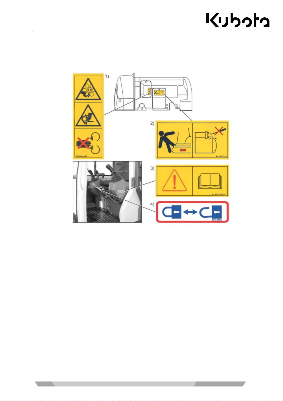
Keep the safety and warning symbols (labels) on the excavator clean and legible, replacing them if necessary.
The positioning of the safety symbols is illustrated in the following figures.
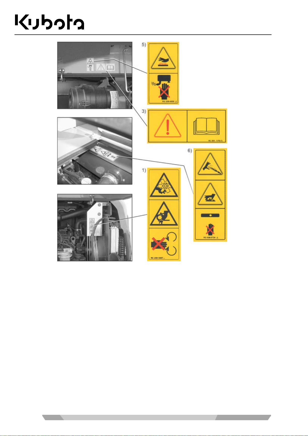
1) Code #: RG 208-4957-0
Keep away from fan and drive belt.
2) Code #: RG 5085723-0
Start the engine only from the operator's seat.
Do not start the engine by shorting the starter terminals.
3) Code #: RG 308 - 5702-0
Read the operating instr uctions and make sure you have understood the manual before
starting or operating the excavator.
4) Code #: 69741-5753-0
17
Page 18
Safety rules
5) Code #: RG 208-4958-0
Do not touch hot parts, such as exhaust muffler, etc.
6) Code #: RG 508-5724-0
Radiator: Risk of scalding.
18
Page 19

Safety rules
7) Code #: R 2491-5736-0
8) Code #: RG 508-5722-0
Do not enter the swivel area.
9) Code #: RG208-5727-0
Do not enter the manoeuvring area.
10) Code #: RG138-5791-0
For information about loosening the crawler, consult the operating instructions.
19
Page 20
Safety rules
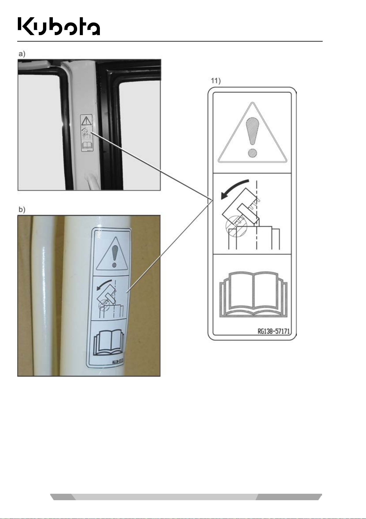
a) Cab version
b) Canopy version
11) Code #: RG138-5717-0
20
When using a wider or de eper bucket take good car e when swinging or pulling in the f r ont
attachments to make sure that the bucket does not hit the cabin or the canopy.
Page 21
Safety rules
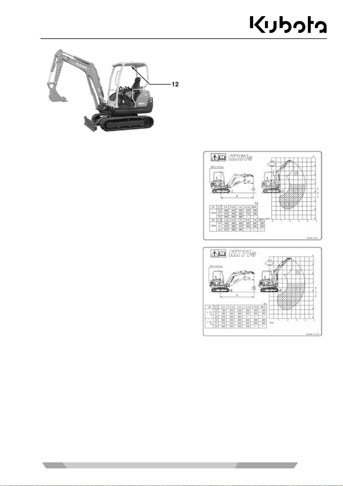
12) Code #: RG248-5747-0
Max. lifting capacity during swivel
operation is 360°
KX61-3 (canopy)
12) Code #: RG448-5747-0
Max. lifting capacity during swivel
operation is 360°
KX71-3 (canopy)
21
Page 22
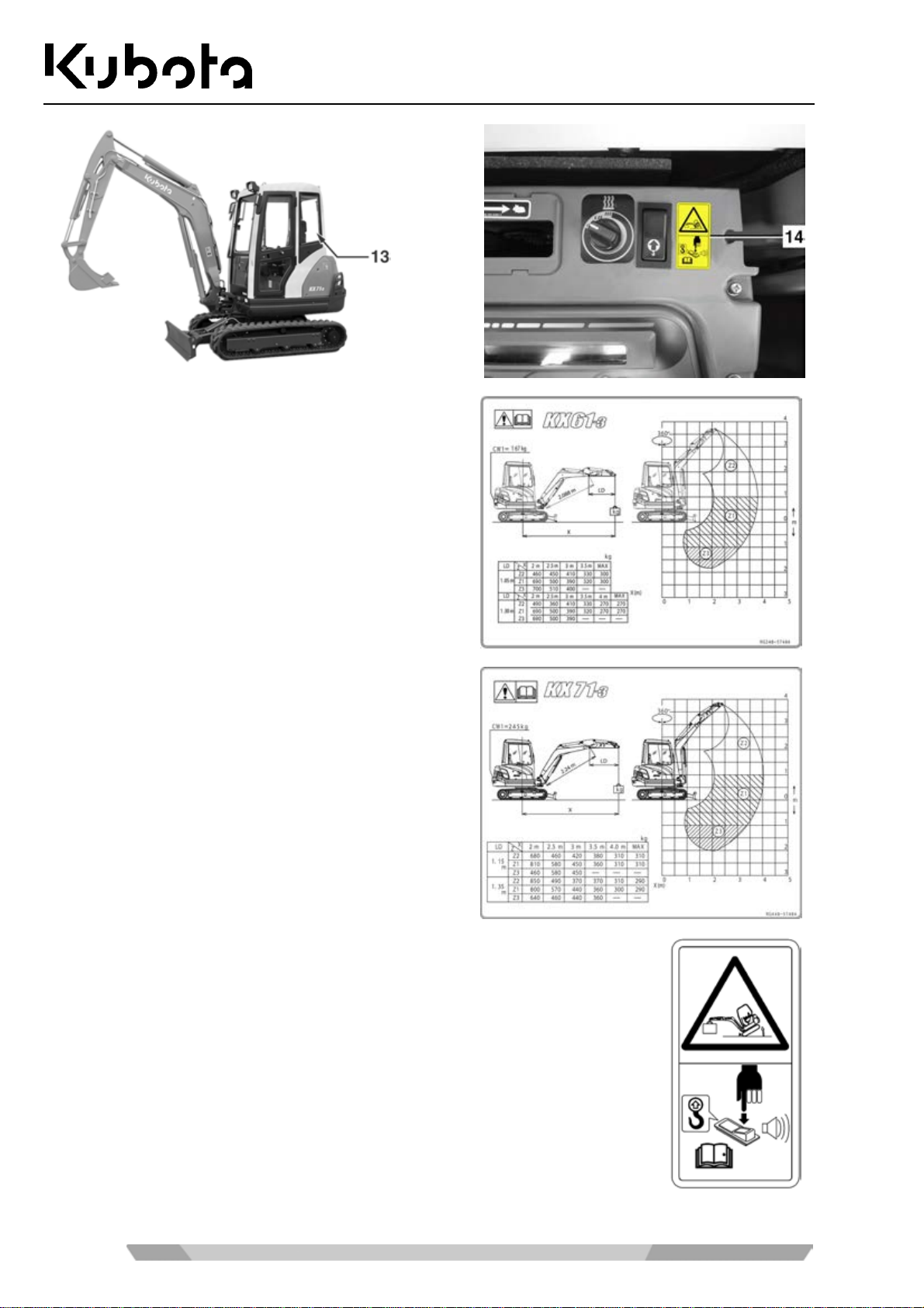
13) Code #: RG248-5748-0
Max. lifting capacity during swivel
operation is 360°
KX61-3 (cab)
Safety rules
13) Code #: RG448-5748-0
Max. lifting capacity during swivel
operation is 360°
KX71-3 (cab)
14)
Code #: RG158-5749-0
Risk of accidents by exceeded load when lifting!
When exceeding the nominal load, a beep sounds and a warning light
illuminates.
• Turn on overload warning function before starting a lifting operation!
22
Page 23
Safety rules
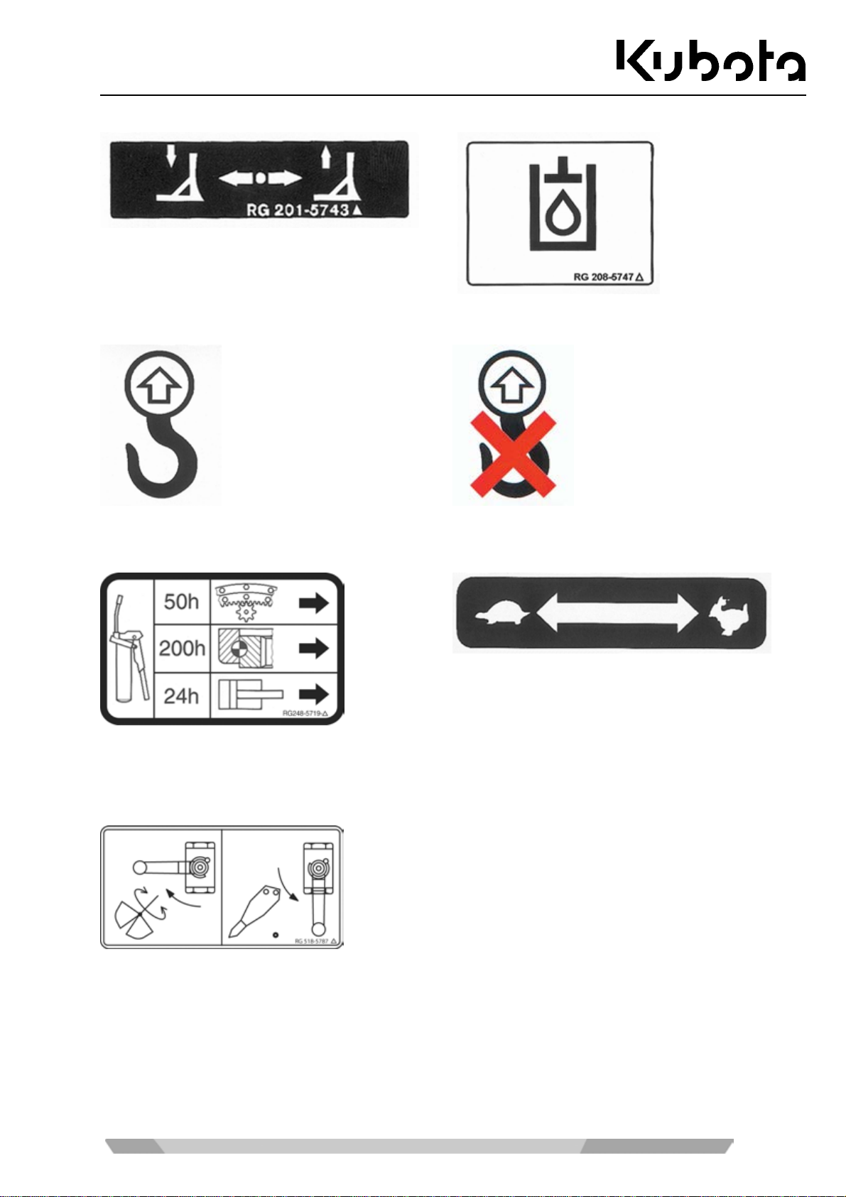
Code #: RG 201-5743-0 Code #: RG 208-5747-0
Code #: RG491-5796-0 Code #: RG109-5769-0
Code #: RG248-5719-0
Code #: RG201-5761-0
Code #: RG 518-5787-0
Set ball valve to match the action of the connected
implement.
23
Page 24
Safety rules
Safety devices
Before starting the exca vator, all saf ety devices m ust be installed pr operly and o perational. No m anipulation of
safety devices, e.g. the shorting of limit switches, is allowed.
Protective devices may only be removed after
• The excavator is standing still and the engine is stopped
• and secured against restarting (starter switch in STOP position and key removed).
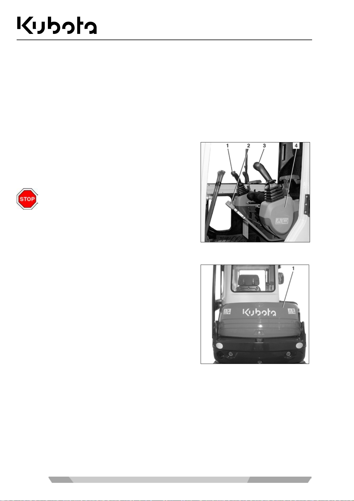
Locking the controls
The control levers (1 and 3) on the right and left, the drive levers
and the dozer control l ever are not operational when th e c ons ole
(4) is raised. This circumstance allows safe getting on and off .
The console is unlocked and raised with the control lever lock
(2).
The boom swing and the dozer functions are not
secured by the control lever lock.
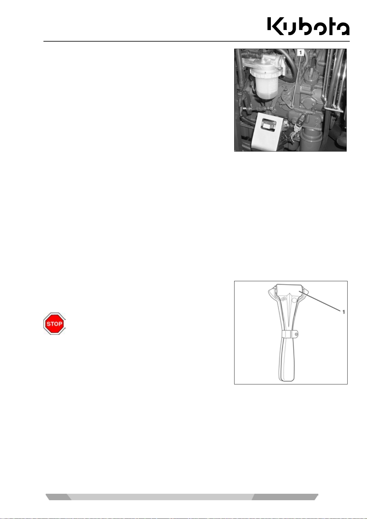
Engine stop knob
The engine is stopped wh en the starter switch is turned to the
STOP position.
If the engine cannot be st opped, pull the stop knob to stop th e
engine.
To stop the engine:
• Open the engine compartment cover (1) (page 82).
24
Page 25
Safety rules
• To stop the engine, push lever (1) to the left unt il the e ngine
is stationary.
Roll-over protection (ROPS)
• The protective roof or cab is designed as roll-over protection (ROPS) and has been tested.
• The seat belt must be fastened while the excavator is being operated.
• Do not make any structural changes to the roll-over protection.
• At the time of damage, please contact your KUBOTA dealer. (Do not repair!)
• Never operate the excavator without the roll-over protection.
With the use of a h ydraulic hamm er or another attach ment f or demolition work, wher e materia l (e.g. asp halt) is
removed and can uncontrollably sputter away, a gravel guard is recommended for protection.
For demolition (acc ording to EN 474- 1, Annex G) , e.g. tearing do wn walls, the cor responding protec tive equipment is required (e.g. gravel guard).
Emergency hammer
In case of an accident where the exc avator cab door and windows can not be opened, the operator can break the window
panes with the emergency hammer (1).
When breaking the wi ndow pane, close your eyes
and cover them with an arm.
Hazards coming from the hydraulic system
If hydraulic oil gets into the eyes, rinse them immediately with clear water and subsequently seek medical aid.
Do not allow hydraulic o il to contact the skin or clothi ng. Skin parts which m ay have come in contact with h y-
draulic oil mus t be washed with water and soap im mediately, if possible. Do t his thoroughly and repeatedly,
otherwise there is a risk of damage to the skin.
Immediately take off any clothes dirtied or soaked with hydraulic oil.
Persons who have inhaled hydraulic oil vapours (mist) should be taken to a doctor immediately.
If leaks have occ urr ed i n th e hydraulic system, the ex c ava tor may not be taken i nt o op erati on or , if i n o perat io n,
operation must cease at once.
25
Page 26
Safety rules
Do not use the nak ed hand to search for leaks; always use a piece of wood or cardboard. Pro tective clothing
(eye protection and gloves) must be worn when seeking leaks.
Leaking hydraulic oi l must be bound imm ediately with an oi l binding agent. T he contaminate d oil binding ag ent
must be stored in suitable containers and in accordance with the valid regulations.
Fire protection
The excavator components and attachments (in parti cular the engine and the exhaust system)
reach high temperatures even at normal working conditions. An electric installation which is
damaged or not prop erly serv iced may lead to flasho vers and/or el ectric arcs . The follow ing Fire
Protection Guidelines may help you ensure the maintenance and efficiency of your equipment
and minimize fire hazards.
• Remove any acc umulated dirt adjacent to hot components, e.g. engine, m uffler, exhaust manifold/tubes ,
etc. If the mac hine is being used to full capac ity, the cleaning procedur e should be performed m ore frequently.
• Accumulated r esidues from plants an d trees, or any other flammable materials , should be removed f rom
the machine. This m ust be observed in particul ar in the proximity of the eng ine and the exhaust system ,
but also at the swivel frame, the track frame, and the boom.
• Check the condition and wear of all fuel lines an d hydraulic hoses. A ny defecti ve parts s hould be r eplaced
immediately in order to avoid leakage.
• Electric lines and connections m ust be checked r egularly for signs of damage. Dam aged components and
lines must be replac ed or repaired before start ing up the machine. All electric connections must be kept
clean and solid.
• Exhaust pipes and mufflers must be checked daily for leaks, damage and any loose or missing joints.
Leaking or damaged exh aust s ystem components must be rep laced or re paired b efore starting u p the machine.
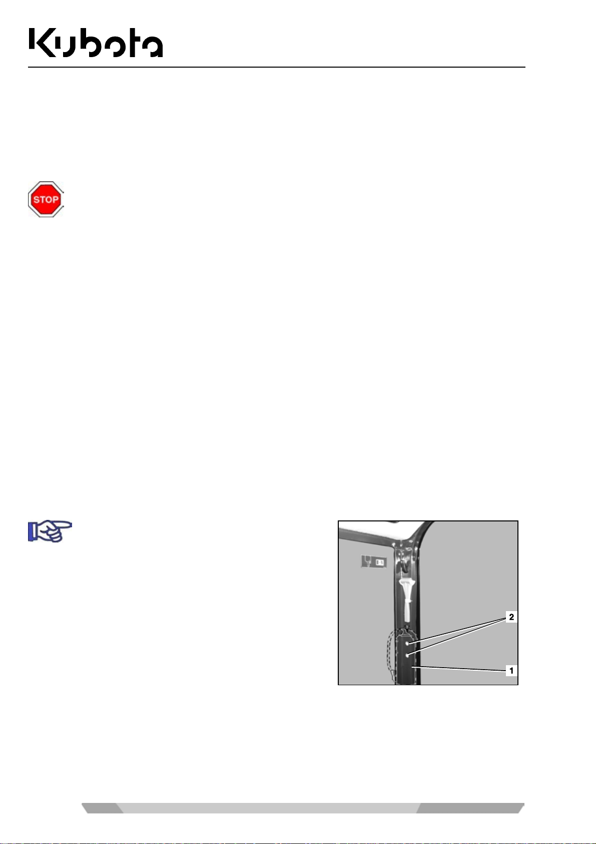
• Always keep a multipurpos e fire extinguisher at or close to the m achine. Make yourself familiar with the
operation of the fire ex tin gu isher . In t he e ve nt of f ire in the e lec tric a l or hydraulic system , us e a CO
tinguisher to combat the fire.
• For attachin g a fire extinguisher (1) two threads (2) have been inserted i n the cab construction on the left
side behind the driver’s seat.
A fire extinguisher is not included in the basic
equipment of the machine.
fire ex-
2
26
Page 27

Recovery, loading and transport
RECOVERY, LOADING AND TRANSPORT
Safety rules for recovery
• For recovery of the ex cavator , a to wing ve hicl e of at le ast the s am e weight c lass as the excav ator m ust be
used.
• A tow bar must be used f or the recovery. If a tow rope is used, an additional vehicle to slow down the
excavator mus t also be att ached. T he tow bar or to w r ope m ust be sui table f or t he rec over y of the excavator in respect of the towed load. Do not use damaged recovery aids.
• Do not step into the danger zone bet ween the vehicles during the recovery procedure. If a tow rope is
used, keep a distance of at least 1½ times the length of the rope.
• Use the towing eye on the track frame for the recovery.
• The above safety rules also apply if the excavator is used as the towing or recovery vehicle.
• Observe the admiss ible values for the towed load and the m aximum pressing load vertical do wn on the
towing eye during recovery, see "Specifications" (page 35).
Safety rules for hoisting the excavator with a crane
• The lifting gear for hoisting must be suitable for the weight of the excavator.
• Before the lifting gear is att ac hed, chec k that the specified safety inspections have been perf ormed and the
lifting gear is in perfect condition.
• The excavator ma y only be lif ted a t the po ints pr o vided . Do no t att ac h the lif ti ng g e ar to the ca b r oof as this
can lead to substantial damage.
• Always adhere to the valid safety regulations for the lifting of loads.
• The excavator must be secured with a holding rope when it is being lifted.
• The crane operator is responsible for the observance of these safety rules.
Safety rules for transport
• The ramps must have a sufficient load capacity for bearing the weight of the excavator. They must be
placed securely on the transport vehicle and fastened.
• Support the loading area at the rear of the transport vehicle with sufficiently dimensioned supports.
• The ramps must be wider than the track of the excavator and have footboards on the side.
• The transport vehicle must be designed for the load of the excavator.
• Place the lef t and the right ram p so that the centre line of the tra nsport vehicle is aligned with the centre
line of the excavator to be loaded.
• Do not drive the excavator onto the transport vehicl e witho ut ramps and with the boom.
• Engage the parking brake of the transport vehicle and secure its front and rear wheels with chocks.
27
Page 28
Recovery, loading and transport
• Secure the excavator aga in s t s liding on the transport vehicl e with c hoc k s or chains or with sui tab le t ied o wn
straps. The chock s must be secured at th e crawlers a nd on the trans port vehic le with su itable m eans. T he
operator of the transport vehicle is responsible for the secure fastening of the excavator on the vehicle.
• A guide is required for dr iving the exc avator ont o an d of f the tr ansport veh icle. The gui de is respons ible f or
the safe loading. The excavator may only be m oved on instruction of the guide; the operator and gui de
must always have eye contact. If this is not possible, the operator must stop the excavator immediately.
• When driving with an excavator loade d, always keep a clearance of 1.0 m to overhead power lines. Ob-
serve the applicable traffic rules and regulations.
Recovery
Adhere to the safety rules (page 12) and the safety
rules for recovery (page 27).
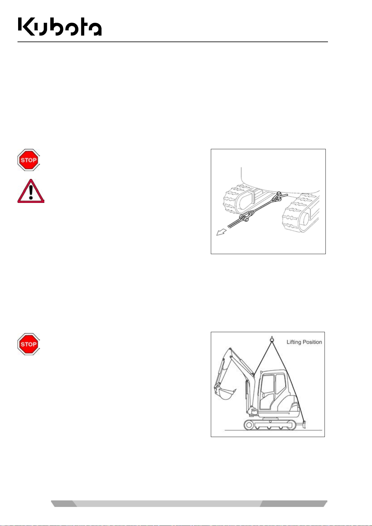
A recovery is only allowed over a short distance
and at walking speed (0.5 m/s ~ 1.0 m/s).
• Attach the tow bar or tow rope to th e to win g e ye (s ee f igure)
on the excavator and to the towing vehicle. The tow bar
should be mounted at a right angle to the vehicles.
• If the towing eye of the excava tor is not accessib le, a tow rope can also be fas tened around the centr e of
the dozer blade.
• During the recovery procedure, the operator must be seated on the operator's place.
• Drive slowly with the towing vehicle to avoid abrupt loads.
Hoisting the excavator with a crane
Adhere to the safety rules (page 12) and the safety
rules for hoisting the excavator with a crane
(page 27).
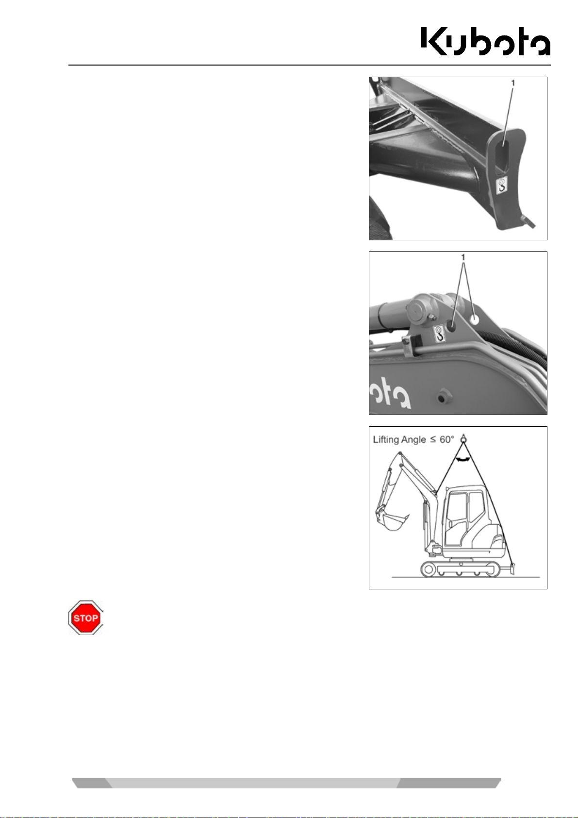
• Bring the excavator to the lifting position (see figure) on
level ground.
• Lift the dozer until the dozer cylinders are fully retracted.
See the "Operating the controls during excavation work"
section (page 62).
• Bring the boom in line with the longitudinal axis of the swivel frame.
• Completely extend the boom cylinder, arm cylinder and bucket cylinder.
• Swivel the swivel frame so that the dozer is located at the rear.
• Close and lock the door and covers.
28
Page 29
Recovery, loading and transport
• Attach the lifting gear with shac kles to the lif ting eyes ( 1) on
each side of the dozer.
• Attach the lifting gear with shac kles to the lif ting eyes ( 1) on
each side of the boom.
• Tension the lifting gear sl ightl y with t he cran e (see f igur e). If
a cab is fitted, plac e cloths between the lifting ge ar and the
cab to protect it.
• Always keep the machine level. Be sure that the c entre line
of the crane hook is aligned as ex actly as poss ible with the
centre line of the excavato r and that the lifting angle is as
specified. Lift the excavator.
The lifting eyes on the cab are not provided for lifting the ex cavator. Do not hoist the excav ator
with these eyes.
29
Page 30
Transport on a flat bed trailer
Recovery, loading and transport
Adhere to the safety rules (page 12) and the safety
rules for transport (page 27).
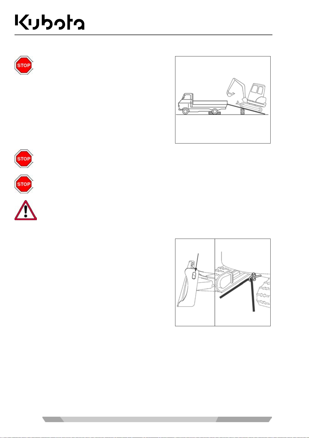
• Place the loading ramps on the transport vehicle at an
angle of 10° to 15°. Observe the track width.
• Bring the excavator exactly into line with the ramps and
drive up straight.
Do not turn or steer while driving up t he ramps; if nece ssary, rev erse the excavator and driv e up
again after realigning it.
DANGER
No person is allowed to stand in the loading area during movement. Risk of bruising.
Take care during swivel operations, the front attachments could thrust against the transport
vehicle. This could damage the transport vehicle and the excavator.
• Turn swivel frame by 180° until the front attachments face the rear of the transport vehicle.
For protecting the vehic le, tie down the points as shown in the
figure.
30
Page 31

Recovery, loading and transport
• For safe attachment, swing out the arm and bucket and
lower the boom to the ground until the bucket linkage
touches the loading area.
• Secure the chains and the dozer with beam s (2).
• Secure the exca vator against sliding on the tr ansport vehi-
cle with chocks or chains (1) (note the vehicle weight).
• Lock the excavator after hoisting.
31
Page 32
Description of the excavator
DESCRIPTION OF THE EXCAVATOR
Model overview
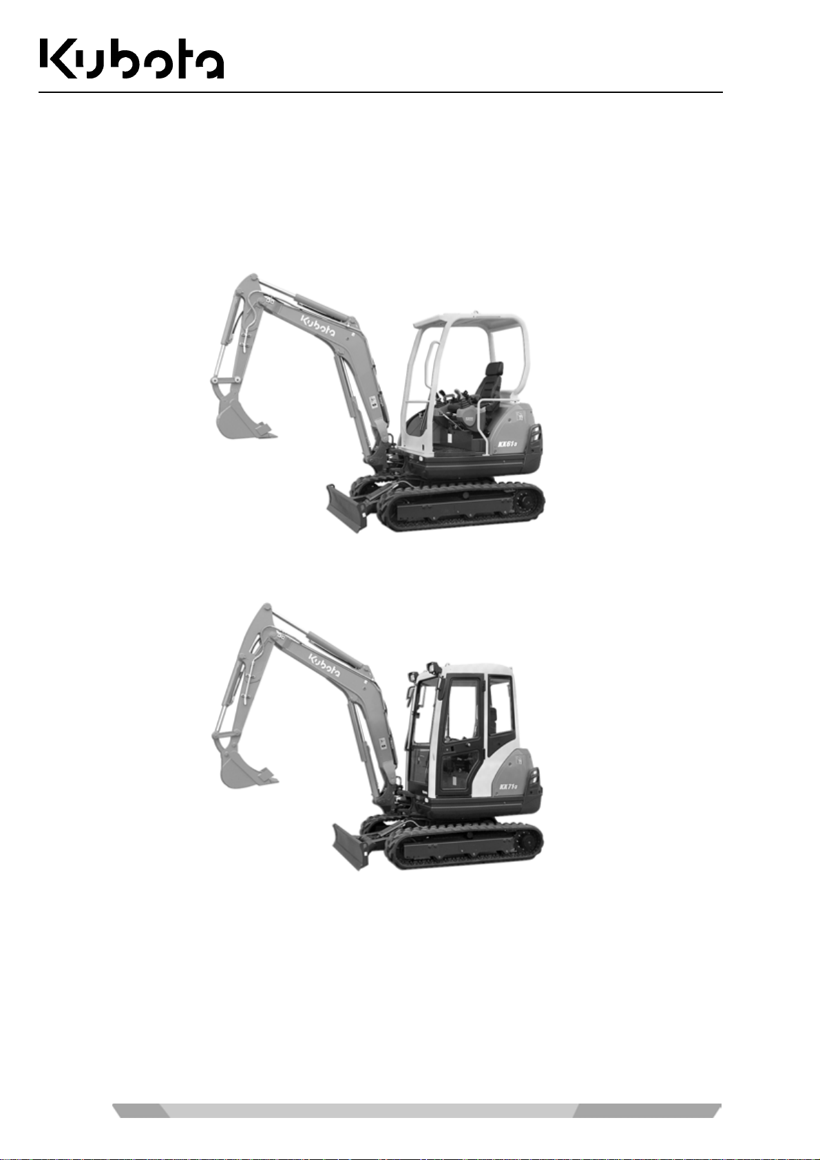
The excavator is supplied in two different models KX61-3 and KX71-3. They are supplied optionally with a
canopy or cab.
Model KX61-3
Model KX71-3
32
Page 33
Description of the excavator
Dimensions
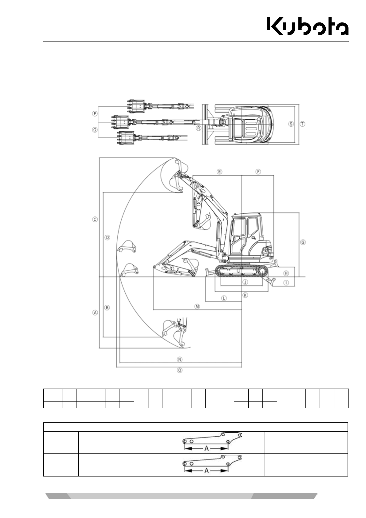
For the dimensions of the KX61-3 and KX71-3, refer to the following figures and the table.
KX61-3 Dimensions
All dimensions in mm
KX61-3 A B C D E F G H I J K L M N O P Q R S T
1* 2490 2050 4360 3060 1830
2* 2740 2290 4540 3240 1880 3150 4600 4720
1160 2410 350 310 1560 1990 1290
3110 4350 4480
600 590 1400 1360 1400
Arm version
Name Type
1* Arm 1050 mm A = 1050 mm
2* Arm 1300 mm A = 1300 mm
33
Page 34
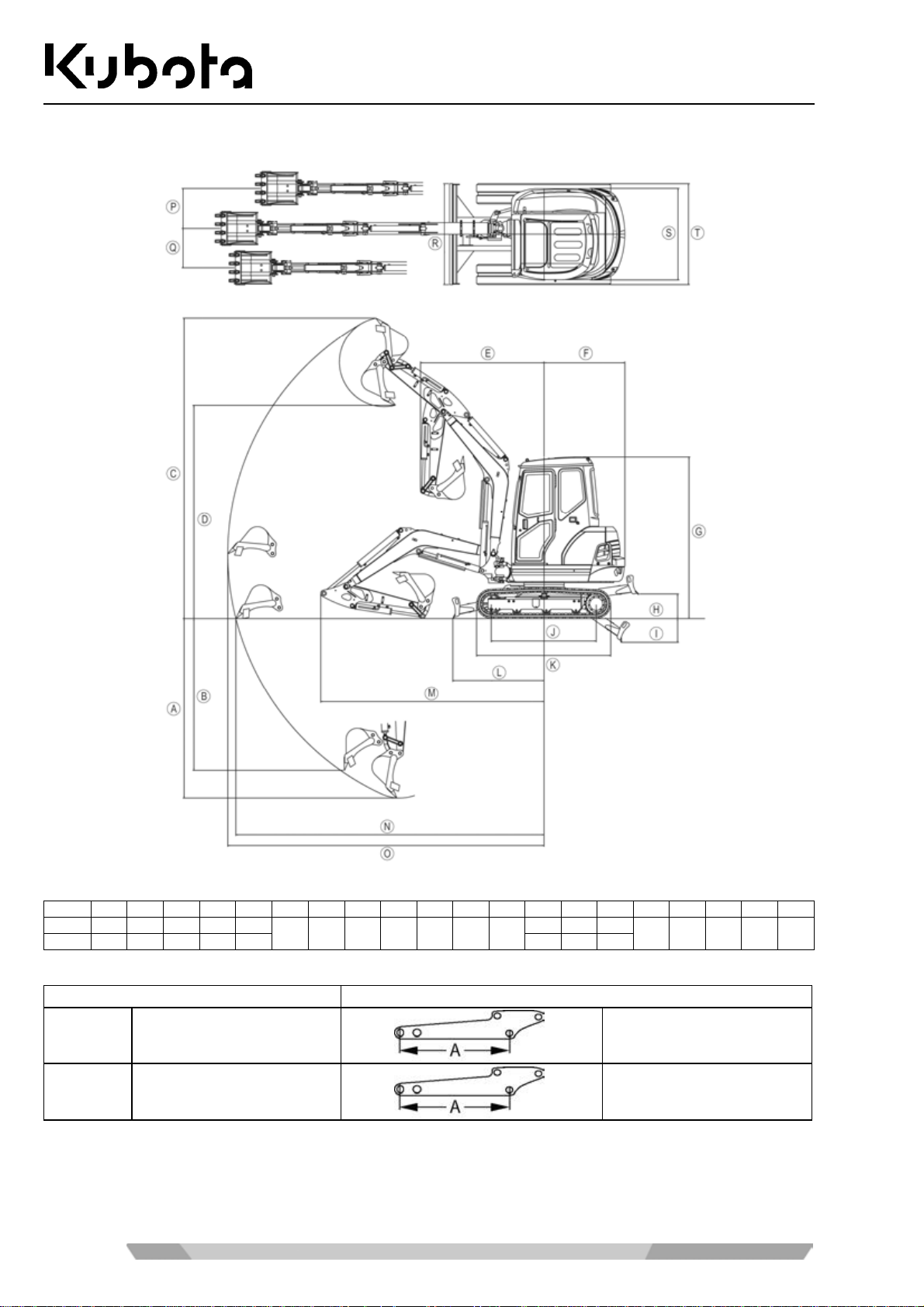
KX71-3 Dimensions
Description of the excavator
All dimensions in mm
KX71-3 A B C D E F G H I J K L M N O P Q R S T
1* 2670 2260 4470 3170 1840
2* 2870 2460 4600 3300 1870 3350 4700 4890
1200 2410 370 350 1560 1990 1360
3320 4580 4770
600 590 1500 1360 1500
Arm version
Name Type
1* Arm 1150 mm A = 1150 mm
2* Arm 1350 mm A = 1350 mm
34
Page 35
Description of the excavator
Specifications
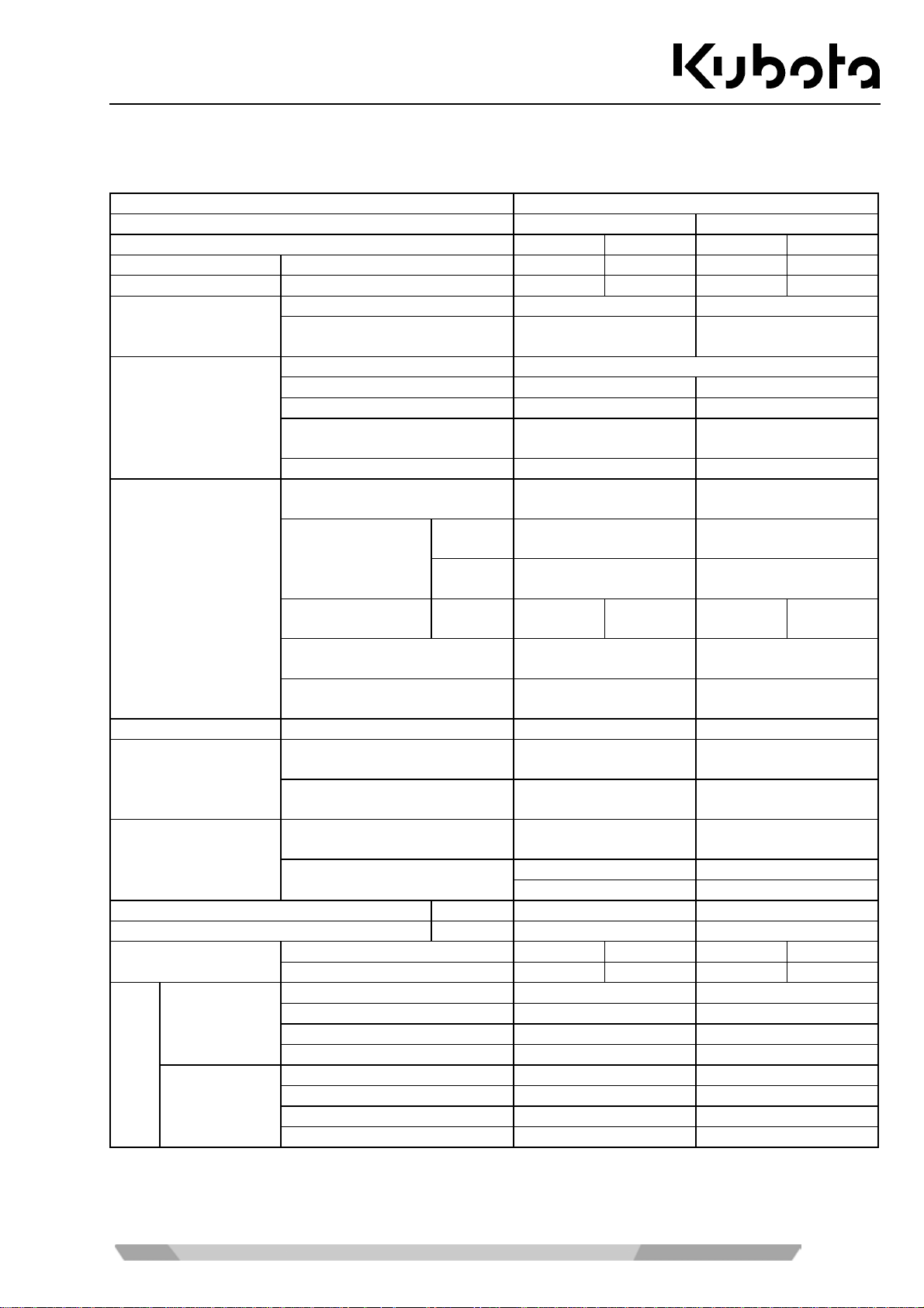
Following are the specifications for these series.
KUBOTA Excavator
Model name KX61-3 KX71-3
Type (rubber crawler) Canopy Cab Canopy Cab
Machine weight* kg 2420 2525 2620 2725
Operating weight** kg 2495 2600 2695 2800
Volume m³ 0.06 0.07
Bucket
Width mm
Type Water-cooled four-cylinder diesel engine
Model name V1505-E2-BH-9EU V1505-E2-BH-10EU
Engine
Displacement cm³ 1498 1498
Engine performance
DIN 70020
kW 18.2 20.5
Rated speed 1/min 2100 2300
Swivel speed
(swivel frame)
1/min 9.5 9.4
fast
km/h
slow
km/h
kPa
(kgf/cm²)
%
(degrees)
%
(degrees)
Performance
Vehicle speed
Ground pressure
(without operator)
Climbing perform ance
max. lateral sway
Dozer width x height mm 1400x300 1500x300
rad
(degrees)
rad
(degrees)
L/min 46.2 50.6
MPa 17.2 20.6
bar 172 206
Swing angle of the
boom
Auxiliary port
left
right
Max. volume
(theoretical)
max. pressure
Volume of the fuel reservoir l 45 45
Pulling capacity at the towing eye N 70540 70540
Noise level
Hand-arm
system
(ISO 5349-2:2001)
LpA dB (A) 77 77 78 79
LwA (2000/14/EC) dB (A) 92 92 94 94
Digging m/s² RMS < 2.5 < 2.5
Levelling m/s² RM S < 2.5 < 2.5
Driving m/s² RMS < 2.5 2.7
Idling m/s² RMS < 2.5 < 2.5
Digging m/s² RMS < 0.5 < 0.5
Whole body
Vibration***
(ISO 2631-1:1997)
Levelling m/s² RM S < 0.5 < 0.5
Driving m/s² R MS < 0.5 < 0 .5
Idling m/s² RMS < 0.5 < 0.5
* With standard bucket 52 kg (KX61-3) or 62 kg (KX71-3), operating readiness established.
** Machine weight incl. operator 75 kg.
*** T hese values are measured under specific conditions at m aximum engine speed and c an deviate, de-
pending on the operating situation.
450 (without teeth)
480 (without teeth)
475 (with teeth)
4.4 4.6
2.8 2.7
22.1
(0.225)
23.1
(0.236)
25.0
(0.255)
36 (20) 36 (20)
27 (15) 27 (15)
1.40 (80) 1.40 (80)
1.05 (60) 1.05 (60)
505 (with teeth)
26.5
(0.270)
35
Page 36
Identification of the excavator
Description of the excavator
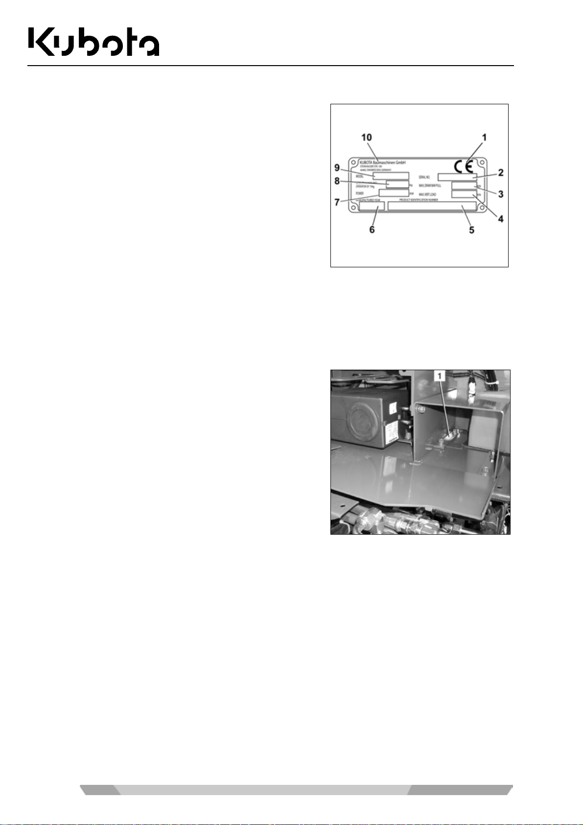
The type plate of the excavator is located at the front of the
swivel frame. The owner s hould enter the stamped data in the
field on the back of the front cover.
1. CE marking
2. Serial #
3. Max. pulling capacity at the towing eye
4. Max. vertical load at the towing eye
5. Product ID number PIN
6. Year of construction
7. Engine performance
8. Operating weight
9. Model name
10. Manufacturer
Equipment
The standard equipment of the excavator can be enhanced by optional equipment (accessories).
Standard equipment
The standard equipm ent of the models includes a grease gun,
an oil filter wrench and a 50 A spare fuse. They are stowed in
the tool compartment (1) under the seat.
36
Page 37
Assembly and functions
ASSEMBLY AND FUNCTIONS
Component overview
1. Boom 11. Dozer cylinder
2. Arm cylinder 12. Dozer
3. Working light 13. Swing bracket
4. Cab 14. Boom cylinder
5. Cab door 15. Bucket
6. Engine compartment cover 16. Bucket linkage 1
7. Drive sprocket 17. Bucket linkage 2 and 3
8. Drive unit 18. Arm
9. Swivel frame 19. Bucket cylinder
10. Idler
37
Page 38
Operator's place
Assembly and functions
The operator's place is located in the middle of the cab. It includes the following control elements:
1. Left control console
2. Drive levers and control pedals
3. Right control console
4. Operator's seat
Right control console
The right control console (see figure) includes the following
components:
1. Right control lever
2. Horn switch
3. Travel speed button
4. Dozer control lever
5. Wrist rest
6. Throttle lever
7. Blower switch (cab version)
8. Display
9. Starter switch
10. Travel speed indicator
11. Rotary beacon button
The display contains the following displays and indicators:
1. Warning light
2. Display
3. Display selector switch
4. Working light button
38
Page 39

Assembly and functions
Description of the components of the right control console
1. Right control lever
The functions of the right control lever are described in the "Controls" section (page 40).
2. Horn switch
Depressing the horn switch activates the horn.
3. Travel speed button
The travel speed button switches the HI speed mode on and off.
4. Dozer control lever
The functions of the dozer control lever are described in the "Controls" section (page 40).
5. Wrist rest
The wrist rest allows fatigue-free operation of the control lever.
6. Throttle lever
The operator can use this lever to set the engine RPM to any desired speed.
7. Blower switch (cab version)
The fan is turned on with the blower switch. The air flow can be set to HI or LO.
8. Display
The functions of the display are described in the "Displays and indicators - description" section (page 39).
9. Starter switch
The starter switch serves as the master switch for the entire machine and as s witch for pre-glowing and
starting the engine.
10. Travel speed indicator
The travel speed indicator lights up when the travel speed mode is activated.
11. Rotary beacon button
The rotary beacon is switched on with this button.
Displays and indicators - description
1. Warning light
The warning light flashes yellow or red when a fault occurs.
Operations must cease immediately when the warning light flashes red.
2. Display
Depending on the operati ng situation, the display sho ws the fuel level, engine tem perature, the hours of
operation, engine s peed and v arious indica tor symbols . The chapt er for the o peration g ives a detai led description of the individual displays based on specific operating situations.
3. Display selector switch
Toggles between two different types of display.
4. Working light button
Switches the working lights on and off.
39
Page 40
Left control console
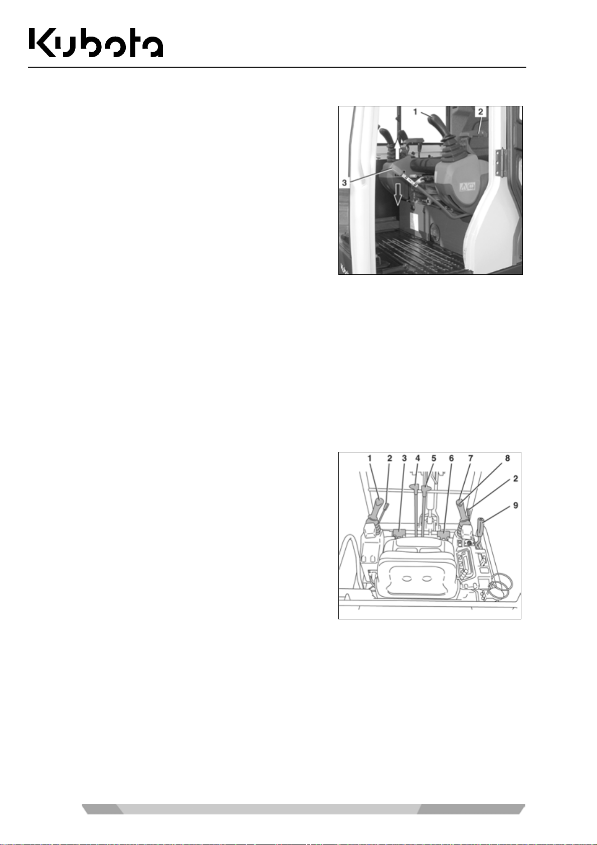
Assembly and functions
The left control console includes the following components:
1. Left control lever
2. Wrist rest
3. Control lever lock
Description of the components of the left control console
1. Left control lever
The functions of the left control lever are described in the "Controls" section (page 40).
2. Wrist rest
The wrist rest allows fatigue-free operation of the control lever.
3. Control lever lock
The operation of the control lever lock is described in the "Controls" section (page 40).
Controls
The controls include the following components:
1. Left control lever
2. Control lever lock
3. Auxiliary port pedal
4. Left drive lever
5. Right drive lever
6. Boom swing pedal
7. Right control lever
8. Horn switch
9. Dozer control lever
40
Page 41
Assembly and functions
Description of the controls
1. Left control lever
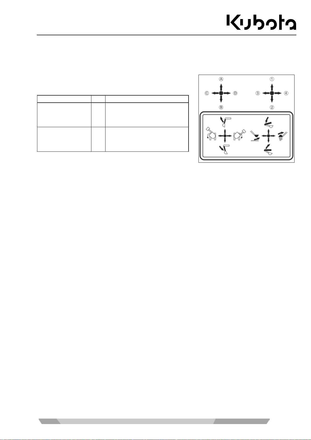
The left control lever is used to swivel the swivel frame and move the arm. See the table below for details.
The figure shows, in connection with the following table, the
functions of the left and right control levers.
Control lever
Right control lever 1
Left control lever A
Movement
Lower boom
2
Raise boom
3
Bucket crowd
4
Bucket dump
Arm dump
B
Arm crowd
C
Swivel frame to the left
D
Swivel frame to the right
2. Control lever lock
To enter and leave the cab, the console must be r ais ed b y pulling up th e c ontr o l le ver loc k. The engine can
only be started if the conso le is r aised. The contro ls ar e onl y operational when th e conso le is lo wered and
the control lever lock is in the "down" position.
3. Auxiliary port pedal
The auxiliary port pedal is used to operate an implement.
4./5. Left and right drive levers
With the drive levers the exc avator can be driven forwards and bac kwards and also turned. T he left drive
lever controls the left track and the right drive lever controls the right track.
6. Boom swing pedal
This pedal is used to swing the boom right and left.
7. Right control lever
The right control lever is used to m ove the b oom and t he buck et. See the f igure above i llustrating th e right
control lever.
8. Horn switch
Depressing the horn switch activates the horn.
9. Dozer control lever
The dozer control lever is used to rais e or lo wer the do zer. P ushi ng the le ver f orward lo wers the dozer an d
pulling it back raises it.
41
Page 42
Further components in the cab
The following details the other components in the cabin.
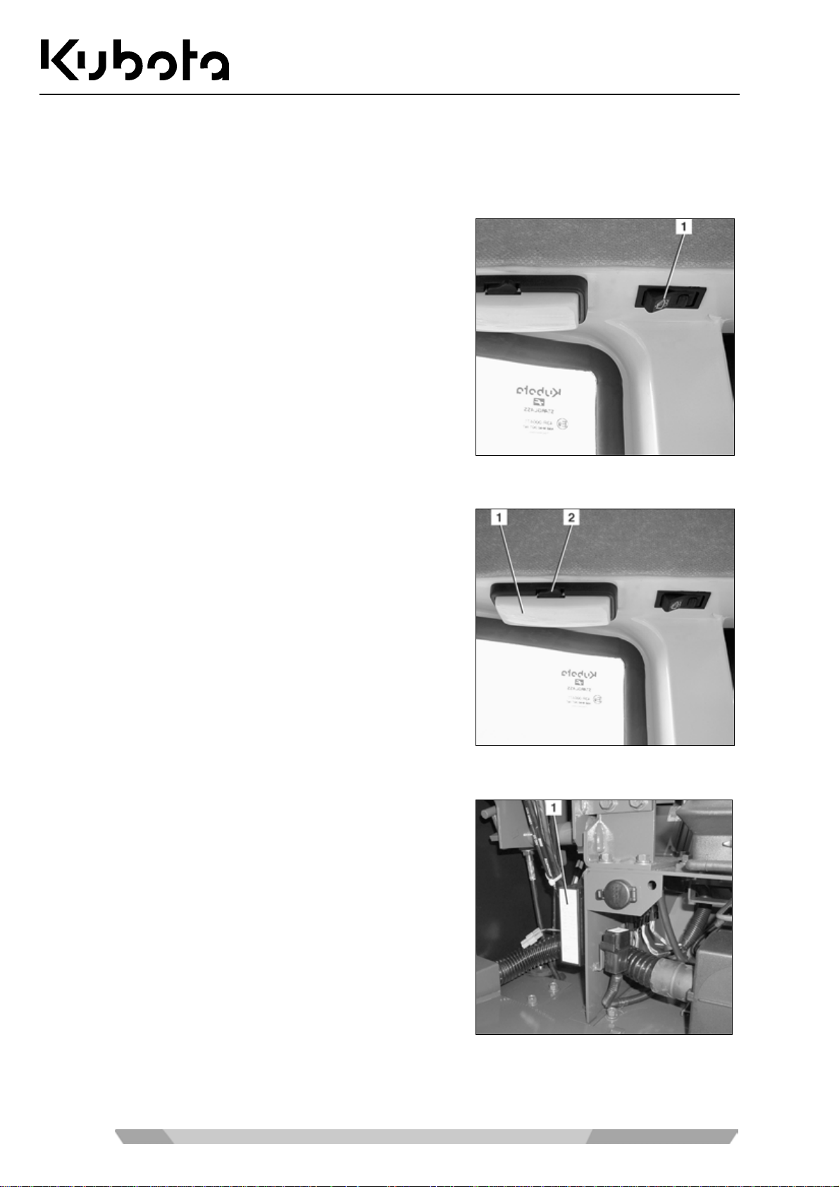
Wiper/washer system
Assembly and functions
The front window is provided with a wiper/washer system. The
system is operated with the wipe/wash switch (1) at the cab roof.
Interior lighting
An interior light ( 1) is locate d on th e lef t side of the cab roof . It is
turned on and off with the toggle switch (2).
Fuse box
The fuse box (1) is located below the operator's seat behind a
cover.
42
Page 43
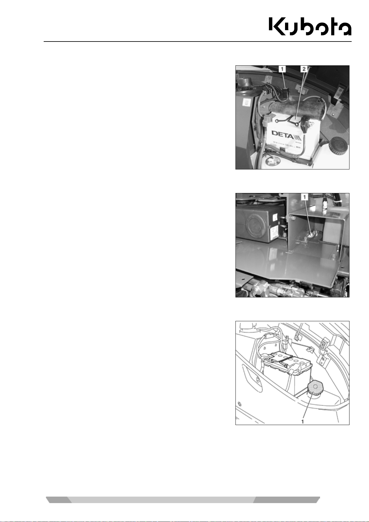
Assembly and functions
Vehicle battery
The vehicle batter y (2) is located on t he right-hand side of the
vehicle above the fuel tank and under the side cover.
The main fuse (1) for the electric system is located above the
main battery.
Tool compartment
The tool compartment (1) is located below the operator's seat.
Fuel tank filler opening
The fuel tank filler opening (1) is positioned under the side
cover. The side cover can be locked.
43
Page 44
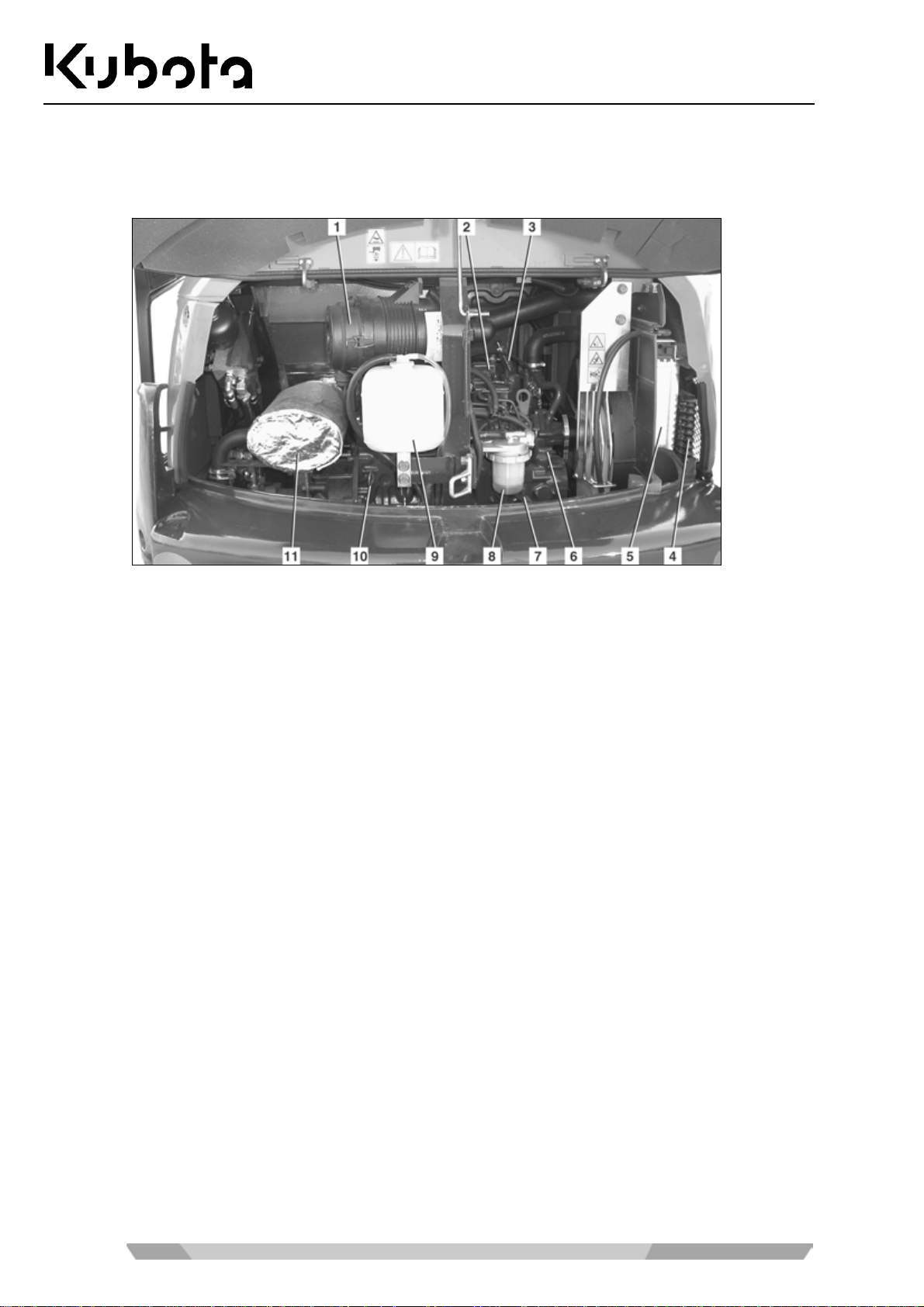
Assembly and functions
Engine compartment
The engine compartment (see figure below) is positioned at the rear of the s wivel frame; it is covered by a
lockable hinged cover.
1. Air filter 7. Engine stop knob
2. Engine 8. Fuel filter
3. Heater valve 9. Coolant expansion reservoir
4. Oil cooler 10. Oil dipstick
5. Radiator 11. Exhaust silencer
6. Oil filler opening
44
Page 45
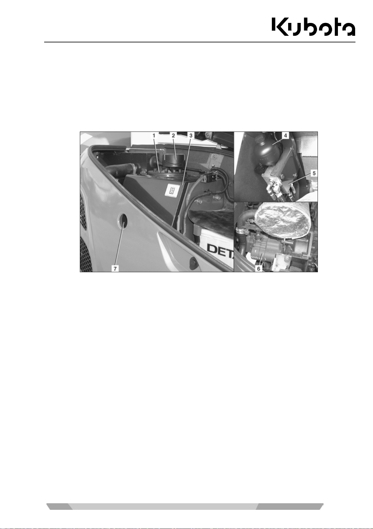
Assembly and functions
Hydraulic system
The controls, except the dozer control lever, the boo m swing pedal, t he auxiliary port pe dal and the driv e levers, activate a pilot control circuit.
The dozer control lever controls the valve via a Bowden cable.
The accumulator (figure below, position 4) allows the boom and arm to be lowered in case of an engine failure.
The hydraulic oil tank contains the suction filter and the return filter.
1. Hydraulic oil tank cap 4. Accumulator
2. Breather filter and 5. Valve block
oil filler port for hydraulic oil 6. Hydraulic oil pump
3. Hydraulic oil tank 7. Sight glass for hydraulic oil level
45
Page 46

Operation
OPERATION
Safety rules for operation
• The safety instructions (page 12) must be followed.
• The excavator may only be operated according to its approved use (page 15).
• The excavator may only be operated by trained personnel (page 11).
• Do not operate the excavator when under the influence of drugs, medication or alcohol. Stop operation
when getting tired. The operator must be physically capable of operating the excavator safely.
• The excavator should only be operated if all protective devices are fully operational.
• Before starting or working with the excavator, make sure that there is no danger for any person nearby.
• Before starting the ex cavator, it must be check ed for external damage and operabi lity, and the pre-start
checks must be carried out. If defects are detected, the excavator should only be taken into operation after
the defects have been repaired.
• Wear tightly fitting working clothes in ac c ordanc e with the trade ass oci ati on re gulatio ns .
• During the operation of the excavator , nobod y except the oper ator is allo wed to be insid e the cab or get o n
the excavator.
• For getting on and off, the swivel f rame should be p ositioned in an a ngle which a llows the oper ator to use
the crawler or the step (if applicable) to enter the cab.
• Always stop th e engine when leaving the cab. I n exceptional cases, e.g. f or troubleshooting, the cab can
also be left with th e engine running. The operator m ust make s ure that the left contr ol console rem ains in
an upright position. The controls may only be used while the operator is sitting on the operator's seat.
• During operation, it is for bidden to stretch any part of the body out of the window or cab d oor, such as
arms, legs, or the body.
• If the operator leaves the excavator (e.g. f or breaks or at the end of work), the engine m us t be s topped an d
the excavator must be s ecured against restart ing by rem oving the key. The cab door m ust be locked. Before leaving the excavator, park the machine so that it can not move.
• Whenever work is interrupted, the bucket must always be lowered to the ground.
• Do not allow the engi ne t o run indoors, unles s t he room is equipped with an exhaust gas ex tr actio n system
or otherwise well ventilated. The ex haust gas contains carbon monox ide, a colourless, od ourless, and lethal gas.
• Never crawl und er the excavator befor e the engine is stopped, the k ey is removed and the excavator is
secured against moving.
• Never crawl under the excavator if it is only rais ed with the buck et or the dozer. Always use suitab le sup-
ports.
46
Page 47

Operation
Safety for child re n
Children are normally attracted to machines and their normal operation. If children are in the
vicinity of the machine and are not at a suita ble distan ce and in the f ield of vis ion of the oper ator,
this can lead to serious accidents or even death of the children.
Always observe the following rules of conduct:
• Never assume that children will remain where you last saw them.
• Keep children far away from the working area and always under the supervision of other responsible
adults.
• Be vigilant and switch the machine off when children enter the working area.
• Never let children drive with you on your machine, there is no safe place for passengers. Children could fall
off the machine and be run over or affect the control of the machine.
• Children must never operate the machine, even under supervision of an adult.
• Never let children play on the machine or attachments.
• Be particular ly careful when manoeuvr ing. Look behind and down belo w on the machine and ensure tha t
there are no children in the manoeuvring area.
• Before leaving the machine, park it so t hat it cannot move . When leaving the machine (e.g. for br eaks or at
the end of work), stop the engine, remove the key and close the cab door, if present.
Guiding the operator
• If the operator's working and driving area is obscured, the operator must be supported by a guide.
• The guide must be capable of performing this kind of work.
• Before starting work, the guide and the operator must agree the necessary signals.
• The guide's position must be clearly visible by the operator.
• The operator must stop the excavator immediately if the eye contact to the guide is interrupted.
→ As a rule, either the excavator or the guide may move, never both at once!
47
Page 48

Operation
Working in the vicinity of overhead power lines
When working with the exc avator i n the v icinit y of over head power l ines a nd tram lines , a m inim um dis tance as
specified in the foll owing table mus t be maintained between the excavator and it s attachments and the p ower
line.
Rated voltage [V] Safe distance [m]
up to 1 kV 1.0 m
over 1 kV up to 110 kV 3.0 m
over 110 kV up to 220 kV 4.0 m
over 220 kV up to 380 kV or when rated voltage is unknown 5.0 m
If safe distances can not be m aintain ed, th e po wer line s m ust be switche d of f in coordination with their o wner or
provider and secured against making them live again.
When approaching overhe ad power lines , an y possible m ovem ents of the ex cavator m us t be taken into cons ideration.
Unevenness of the ground or sloping the excavator can reduce the safe distance.
Wind can cause the overhead power lines to sway, thus reducing the safe distance.
In case of a power cr oss-over, leave the danger zone with the excavator , if possible, b y taking suitab le meas-
ures. If this is not poss ible, do not leave the operator's place, war n any approaching persons of the da nger , an d
have the power switched off.
Working in the vicinity of underground power lines
Before starting with excavation work , the owner of the ex cavator or the pers on responsible for the work must
check if there are any underground power lines in the proposed working area.
If there are undergroun d power lines present, the position and routing of the power lines mus t be determined
together with the owners or operators and the required safety measures must be determined.
If power lines are encounter ed or accidentally damaged, the operator must stop working immediately and inform the responsible person.
48
Page 49
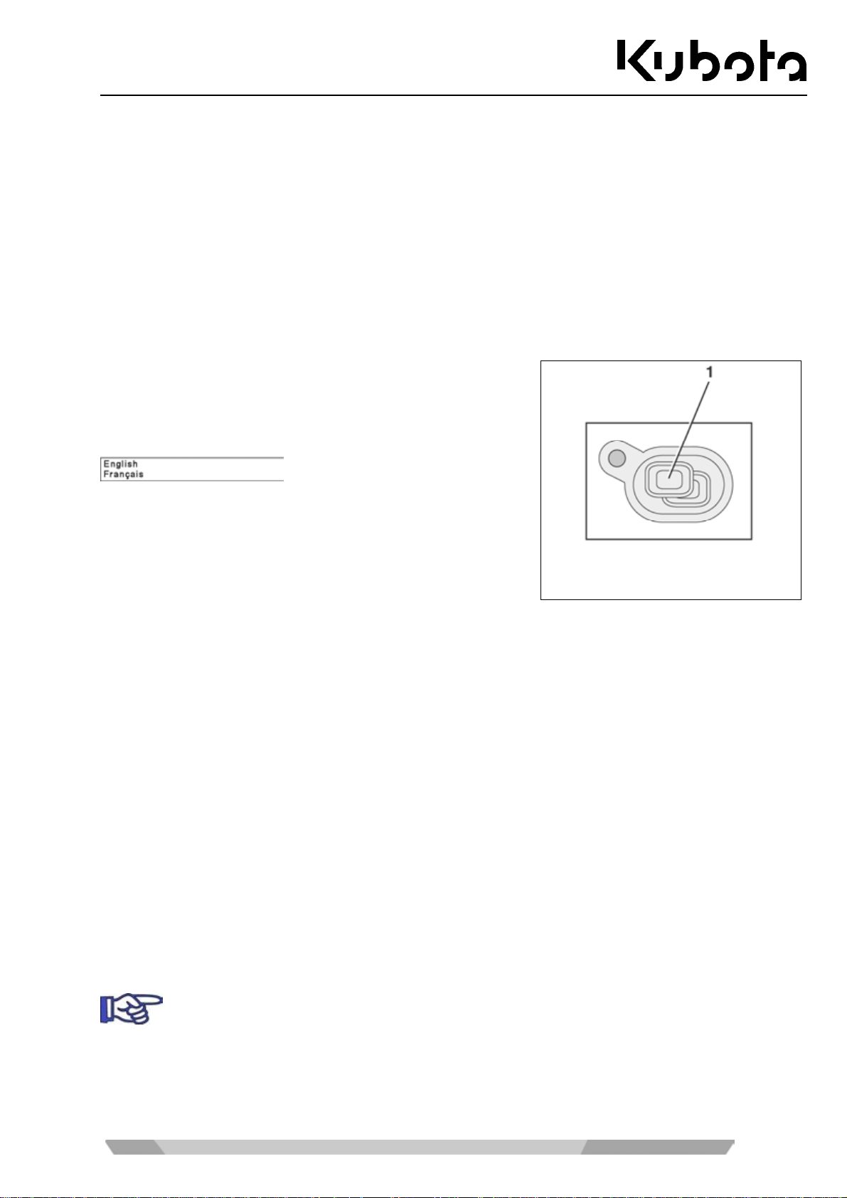
Operation
Initial operation
Before initial operation, the excavator must first be checked vis ua lly for external transit d amages and checked if
the shipped equipment is complete as ordered.
• Check fluid levels as described in the "Maintenance" section (page 91).
• For a description of all operation features, see t he "Operating the excavator" s ection (page 49) as well as
the following sections.
If defects are detected, please inform your dealer immediately.
Setting the display language
• Press and ho ld the display selector s witch (1) and turn the
starter switch to the RUN position at the same time. The
model is shown in the displa y. Release the d isplay sel ector
switch to show the currently selected language.
• To select the desired language, repeatedly press the dis-
play selector switch until the desired language is shown.
Press and hold the displa y selector switch to store the selected language.
Running-in of the excavator
During the first 50 hours of operation, the following points should be adhered to in all cases:
• Warm up the excavat or at an average engine speed and with a low load; do no t let it warm up at idling
position.
• Do not overload the excavator.
Special maintenance instructions
• Change the oil in the final drives after the first 50 hours of operation.
• Change the return filter of the hydraulic system after the first 250 hours of operation.
Operating the excavator
For a safe excavator operation, see the following sections.
Pre-operational services
For the performance of the services , the excavator mus t be parked on lev el ground and the key
must be removed.
• Open the engine compartm ent c ov er ( page 82). A l wa ys c lose the eng in e c ompartment cover after the work
is done.
49
Page 50
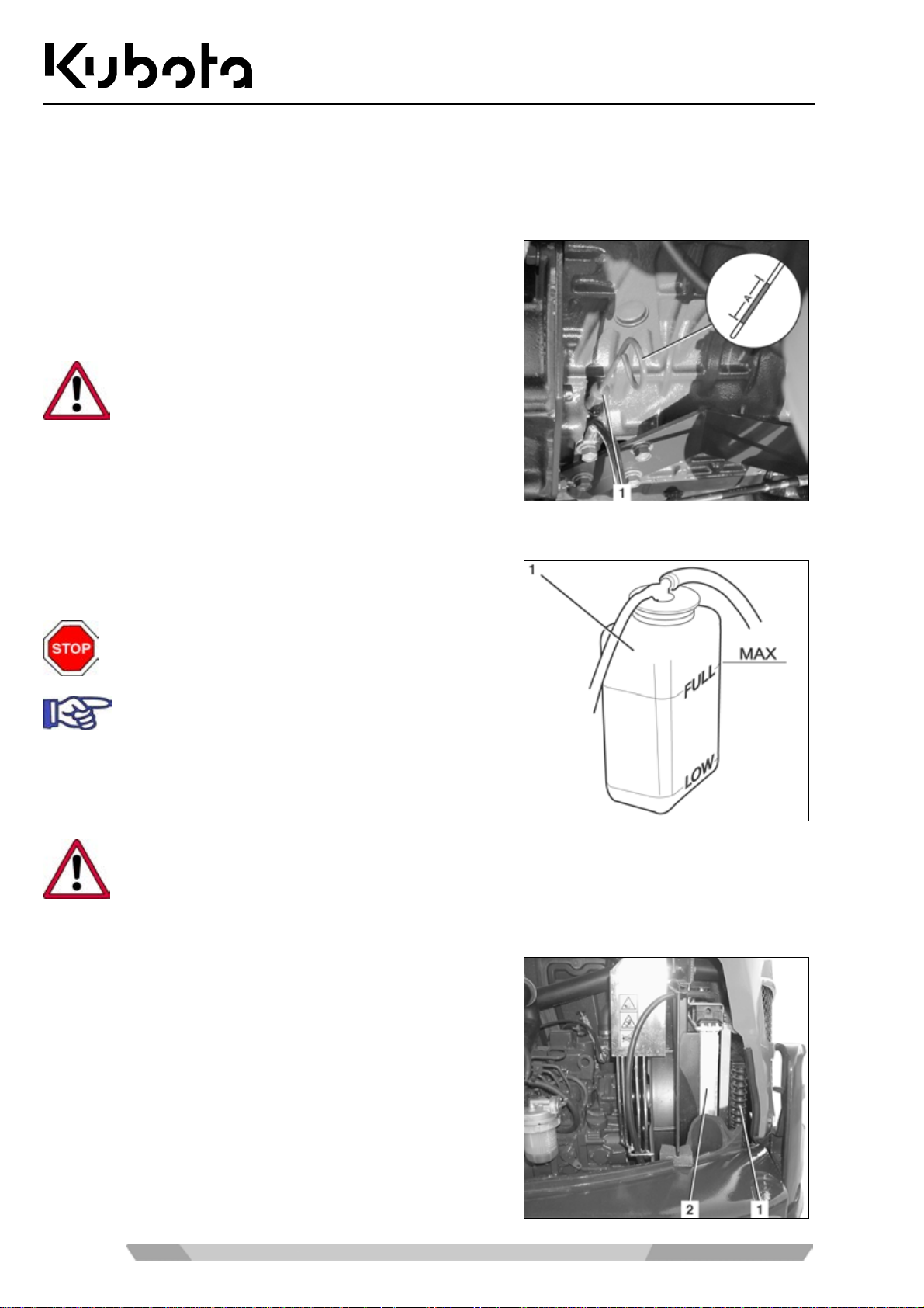
Visual inspection
• Check the excavator for visible damage and leaks.
Check the engine oil level
Operation
• Pull out the oil dipstick (1) and wipe it with a clean cloth.
• Insert the oil dipstick c ompletely and pull it out again. The
oil level should be in the " A" area. If the oil level is too low,
add engine oil (page 99).
When the oil level is to o high or too low, the engine
might get damaged during operation.
Checking the coolant level
• Check the c oolant level in the exp ansion reservoir (1) . The
fluid level must be between FULL and LOW.
Do not open the radiator cap.
If the coolant level is below the LOW mark, refill
(page 96).
If the coolant level is below the LOW mark a short time after adding coolant, the cooling system
is leaky. The excavator must only be started again after the fault is repaired.
Checking the radiator and the oil cooler
• Check the radiator (2) and oil c ool er (1) f or leak s and debris
(e.g. leaves).
• If there are leaves or other debris between th e radiator and
cooler, clean the radiator (page 97).
50
Page 51
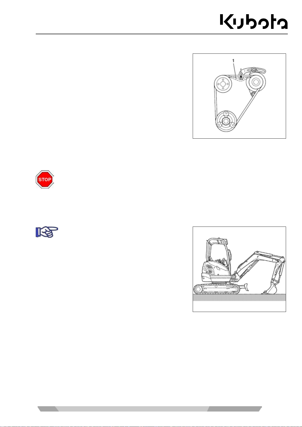
Operation
Checking the V-belt
• Check the V-belt (1) for cracks and proper tens ion. It shou ld
be possible to depress the V-belt for about 10 mm. Tighten
the V-belt (page 97).
Checking the exhaust system for leaks
• Check the exhaust system for leaks and security (formation of cracks).
If the inspection is carr ied out when the engine is warm, there is a risk of burns at the exhaust
system.
• If the exhaust s ystem is leaky or loose, the ex cavator may only be tak en into operation after the def ects
are eliminated.
Checking the oil level of the hydraulic system
To determine the oil level exactly, extend all hydraulic cylinders half way.
51
Page 52
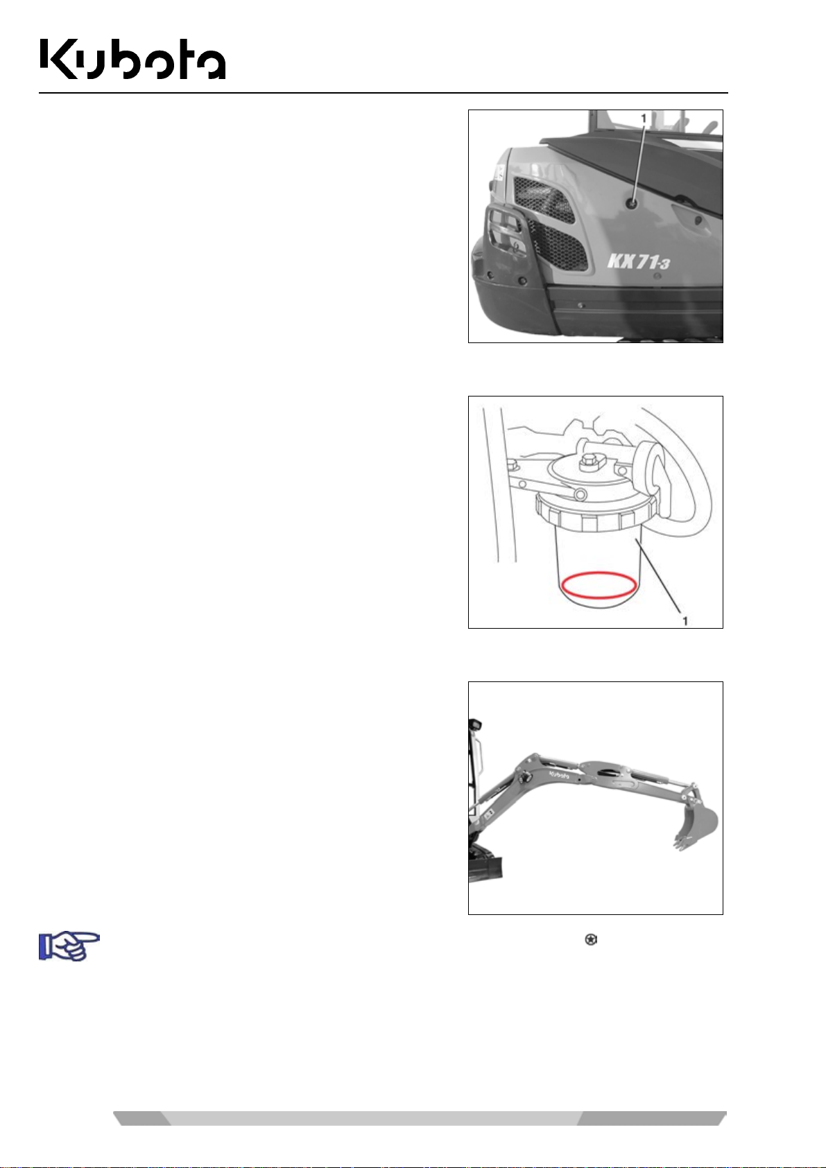
Check the oil leve l in the sight glas s (1). The oil level should be
half way up the sight g lass. Carefully check the position of the
hydraulic cylinders aga in before topping up. For more inform ation, see the "Topping up hydraulic oil" section (page 105).
Checking the water separator of the fuel system
Operation
• A red plastic ring in the water separator (1) floats up with
the water level. If the ring is floating up, clean the water
separator (page 102).
Lubrication
• Start the engine (page 56).
• Position the boom , arm, bucket and dozer as shown in the
figure. Stop the engine, re m ove the k ey. See the "Op eratin g
the controls" section (page 62).
• Lubricate a ll grease points (s ee figure below) with gre ase -
see the "Recommended lu bric ants" sec tion (pa ge 116) - until fresh grease emerges.
52
During the first 50 hours of operation, grease all grease nipples marked
grease.
using "Anti-Seize"
Page 53
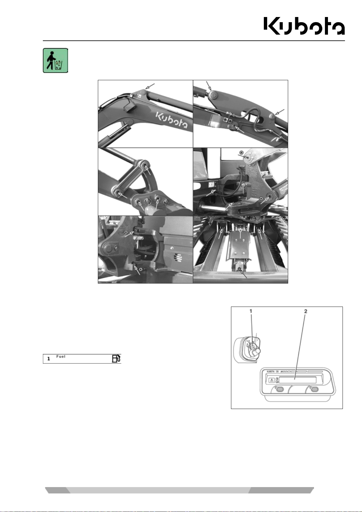
Operation
Wipe emerged grease off imme diately and store dirty cleaning c loths in the containers prov ided
for disposal.
Checking the fuel level of the fuel tank
• Turn the starter switch (1) to the RUN position.
• Check the fuel level at the fuel ga uge (2). If "Fue l" is shown
in the display, there are only 5.1 L of fuel left in the fuel
tank.
• If the fuel level is too low, refuel the excavator (page 80).
Setting up the workplace
For cab versions, refer to the "Opening and closing the cab door" section (page 74).
53
Page 54
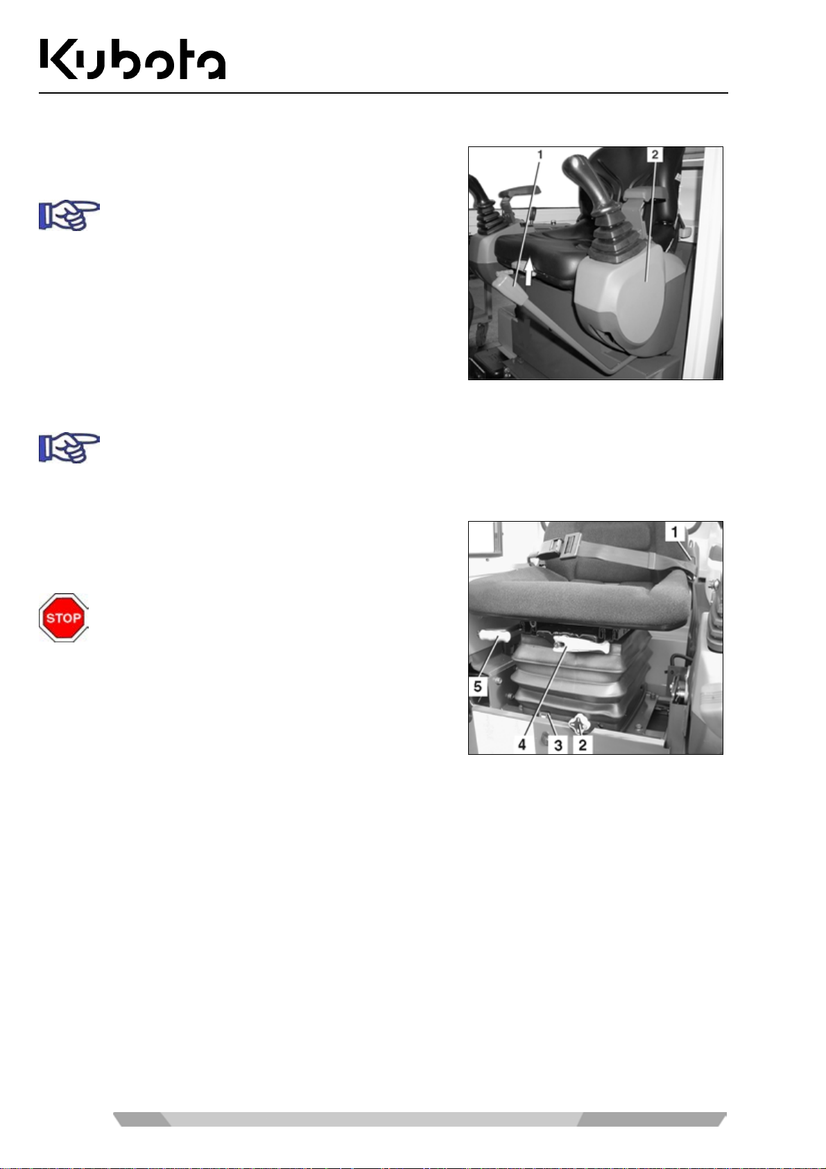
Getting on the excavator
Operation
• Move the left control console (2) up as far as possible by
pulling the control lever lock (1) up.
The control console must remain in this position
until the engine is started, as the engine can only
be started in this position.
• Get on the excavator by using the crawler as a step.
• Sit down on the operator's seat.
Adjusting the operator's seat
Adjust the operator's s eat so that fatigue-free and comforta ble working is possible. It s hould be
possible to operate all controls safely.
Horizontal seat adjustment (seat stand-off)
Pull the horizontal seat adjustment lever (5) up and move the
seat to the desired positio n by moving it forward or back, then
release the lever.
Check that the seat is locked into place.
Spring adjustment (operator's weight)
• The seat can be set to the weight of the operator with the adjustm ent grip (figure above, position 4). A
weight indicator (figure above, position 3) is provided as an adjustment aid.
• Turning the grip clockwise increases spring tension (heavier operator) , turning the grip anticloc kwise re-
duces spring tension (lighter operator).
• Adjust the seat so that a comfortable cushioning is achieved.
Seat height adjustment (knee height)
• The seat height is adj usted with t he rotar y knob (f igure above , posit ion 2) . The s eat h eight depends on the
set number (0, I, II, III), position 0 bein g the lo west positi on. Adjus t the seat h eight in relatio n to its hor izontal position so that the foot controls can be operated safely.
54
Page 55
Operation
Backrest adjustment
• Take the load off the back rest and pull up the bac krest adj ustm ent lever (f igure abov e, posit ion 1). Set t he
backrest to the desired sitting positi on and release t he lever. The backrest should be adjusted so th at the
operator can safely operate the control levers with the back resting completely on the backrest.
Seat belt
• Fasten the seat belt.
• Adjust the length of the seat belt by lengthening or shortening the belt so that the belt fits comfortably.
Do not operate the excavator without the seat belt fastened.
Exterior mirror adjustment
• Check the adjustment of the exterior mirrors. If necessary, adjust the mirrors until the optimum sight is
Safety instructions for starting the engine
ensured.
The excavator is equipped with an anti-theft system (page 84).
When starting the excavat or for the first time on a work day, carry out the pre- operational services (page 49).
Make sure that there are no pers ons within the excavator's wor king area. It is essential to warn
persons in the vicinity of the excavator by briefly honking the horn.
Make sure that all operational controls are in the neutral position.
Starting the excavator is only allowed when the operator is sitting on the operator's seat.
Before starting the engine, make the necessary operator station adjustments (page 53).
If the engine does not start immediately, cease the starting procedure. Wait a short ti me before
reattempting a start . If th e eng ine do es not start after several at tem pts, con tact s kill ed pers onnel.
If the battery is discharged, jump-start the excavator (page 78).
Do not use Start Pilot or similar substances as a starting aid.
55
Page 56
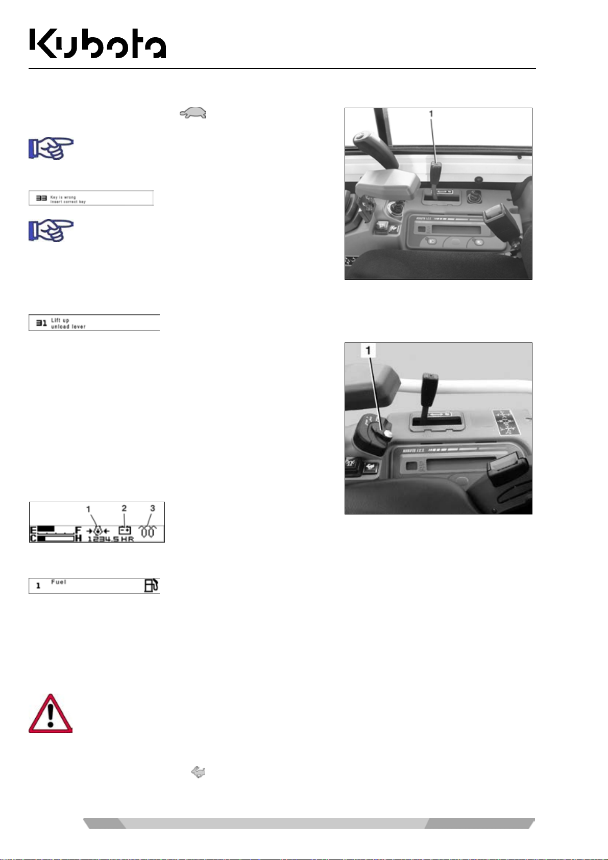
Starting the engine
• Move the throttle lever (1) to .
The excavator is equipped with an anti-theft system. If someone tries to start the excav ator with the
wrong key, the following message will be displayed:
If the bunch of keys contains metal parts, such as
key rings or other keys, the engine might fail to
start.
If the control lever lock is not raised, the following message will be displayed:
Operation
• Insert the key into the starter switch (1) and turn it to the
RUN position.
The preglowing indicator (display indication below, position 3)
comes on briefly. The engine can be started after it goes off.
The engine oil pressure indicator (display below, position 1)
lights up and goes off after the engine has started.
The charge lamp ( display indication below, position 2) lights up
and goes off after the engine has started.
If Fuel is shown in the display, there are only 5.1 L of fuel left in the fuel tank. Refuel the excavator (page 80).
• Turn the starter switch to the START position and hold it ther e until the engine has st arted. Release the
starter switch.
• Lower the left control console and make sure that the control lever lock engages.
• Run the engine briefly at idling speed.
Operate the engine at low speed until the perating temperature is reached.
Set the engine speed required for operation:
• Move the throttle lever towards
until the engine reaches the required speed.
56
Page 57
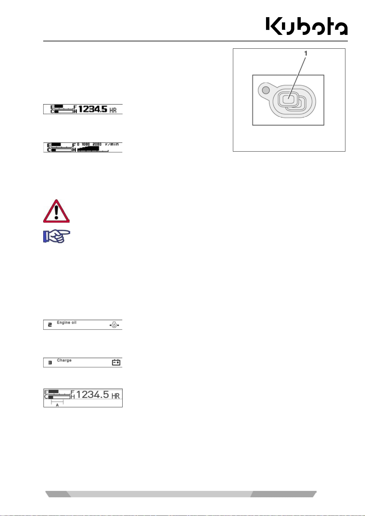
Operation
Using the display selec t or sw itch ( 1) you can switch between the
engine speed and the hours of operation.
The time meter (display indication below) shows the actual
hours of operation of the excavator (independent from the engine speed).
The speed indicator (d isplay ind ication be low) shows t he curr ent
engine speed.
Check the displays and indicators during operation (page 57).
Stopping the engine
Make sure idle spe ed is set when stop ping the engine. W hen stopping the engin e with a higher
speed, the turbocharger may get damaged due to insufficient lubrication.
If the engine is to be stopped to tak e the excavator o ut of operation, the serv ices for placing the
excavator out of operation (page 70) must be carried out.
• Turn the starter switch to the STOP position and remove the key.
Observation of the displays after starting and during operation
The operator must observe the indicators and displays after starting and during operation.
If the "Engine oil" m essage appears during o peration, stop the en gine immediatel y and contact sk illed personnel.
If the "Charge" message appears during operation, stop the engine immediately. Check if the V-belt is very
loose or broken; if necessary, contact skilled personnel.
Watch the coolant temperature gauge, the bar should be inside the "A" range.
If the bar rises toward s the "H" du ring excavat or operat ion, stop th e engine immed iately and ch eck th e
coolant level in the expansion reservoir. Do not open the radiator cap → risk of scalding . If the water
level is below the "LOW" mark, allow the engine to cool completely and add coolant (page 96).
Check the cooling system for leaks; if necessary, contact skilled personnel.
Check if the V-belt is very loose or broken; if necessary, contact skilled personnel.
57
Page 58
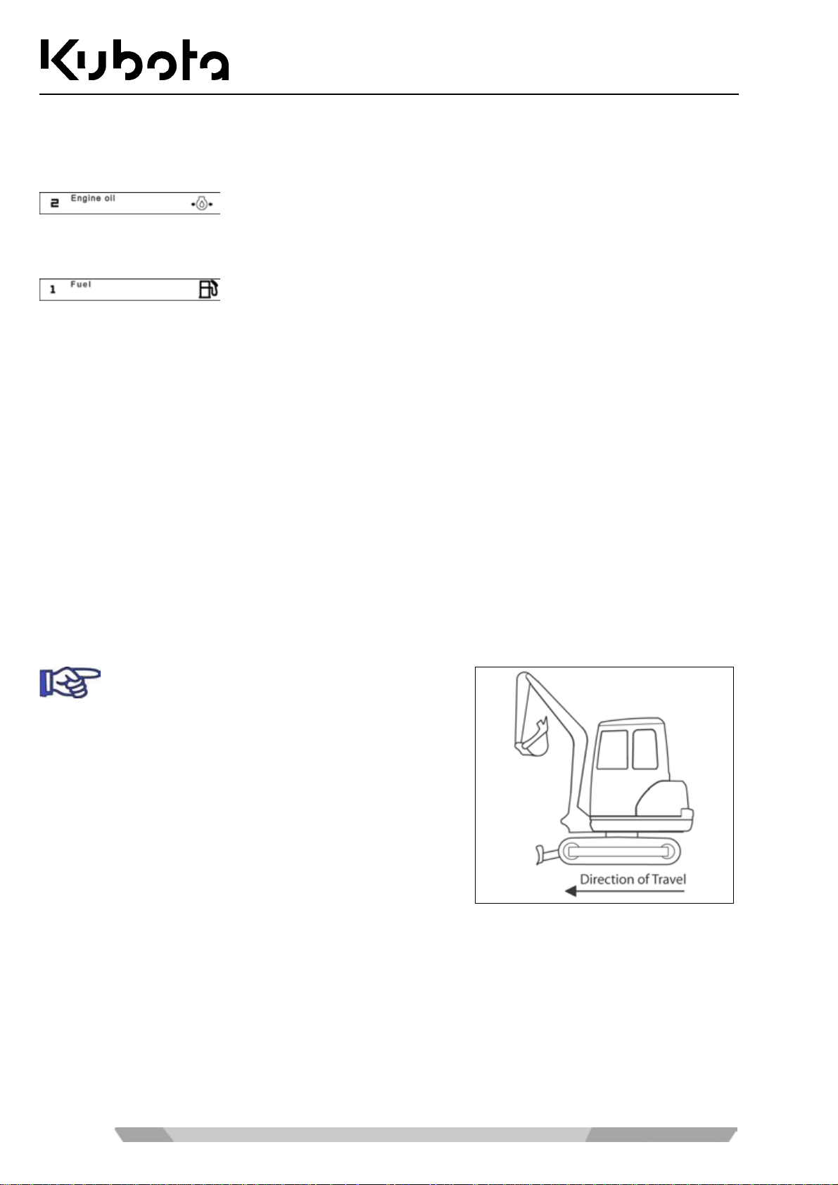
Operation
Check if the air intak e in the right side panel, the radiator and the oi l cooler are very dirt y. If necessary, clean
the radiator (page 97).
The same applies if the warning light flashes red and the following message displays:
Watch the fuel gauge. If the bar is near to the "E", refuel the excavator (page 80). The same applies if the
warning light (5.1 L of fuel remaining) flashes yellow and the following message displays:
Also stop the engine immediately if
• the engine speed rises or drops suddenly,
• abnormal noises are heard,
• the excavating devices do not respond to the control lever as expected or
• the exhaust fumes are black or white. When the engine is still cold, white smoke for a short time is normal.
Driving the excavator
• Adhere to the general safety rules (page 12) and the safety rules for operation (page 46).
• Carry out pre-operational services (page 49).
• Start the engine (page 56).
• Check the displays and indicators (page 57).
Ensure that the boom and the dozer are in the
direction of travel as shown in the figure.
58
Page 59
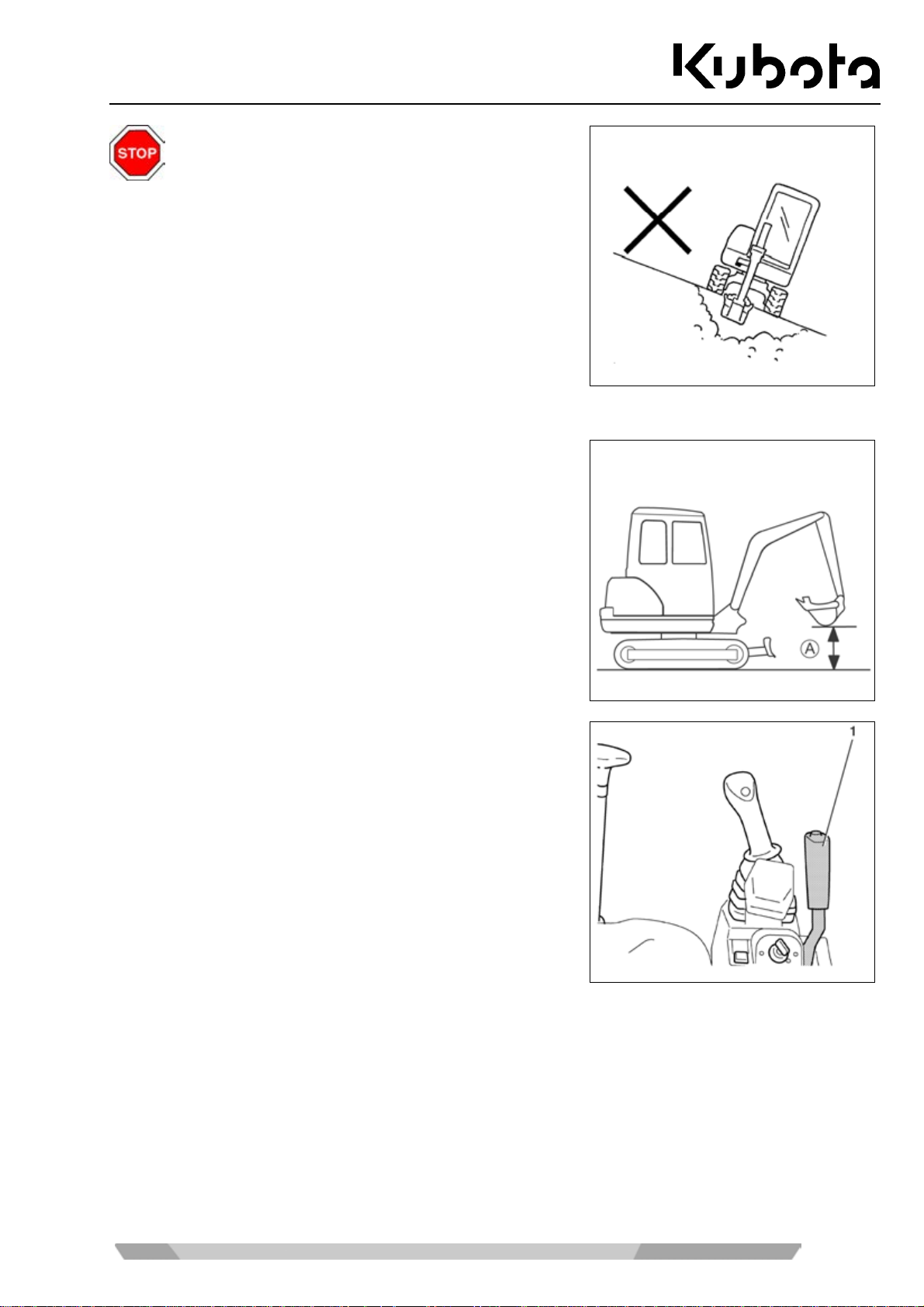
Operation
When driving with the excavator, always observe
the following safety instructions.
When working on slopes, observe the tilt of the excavator ( see
figure).
Max. lateral sway → 27 % resp. 15°
Climbing perform ance → 36 % resp. 20°
• Keep the bucket as low as possible when driving.
• Check the ground for s tability, and verify if there are hol es
or other potential obstacles.
• Approach overhangs and edges of ditches caref ully as the y
could cave in.
• Drive slowly downhill, do not allow the vehicle speed to
increase uncontrollably.
• Close the cab door.
• When driving, the bucket s hould be approx . 200 to 4 00 mm
(A) above the ground (see figure).
• Raise the dozer to the top position by pulling the dozer
control lever (1) back.
• Select an appropriate engine speed.
Driving
• Push both drive l evers simultaneously forward to drive the excavator straig ht. Releasing the drive lever s
stops the excavator immediately.
To reverse the excavator, pull both drive levers back simultaneously.
59
Page 60
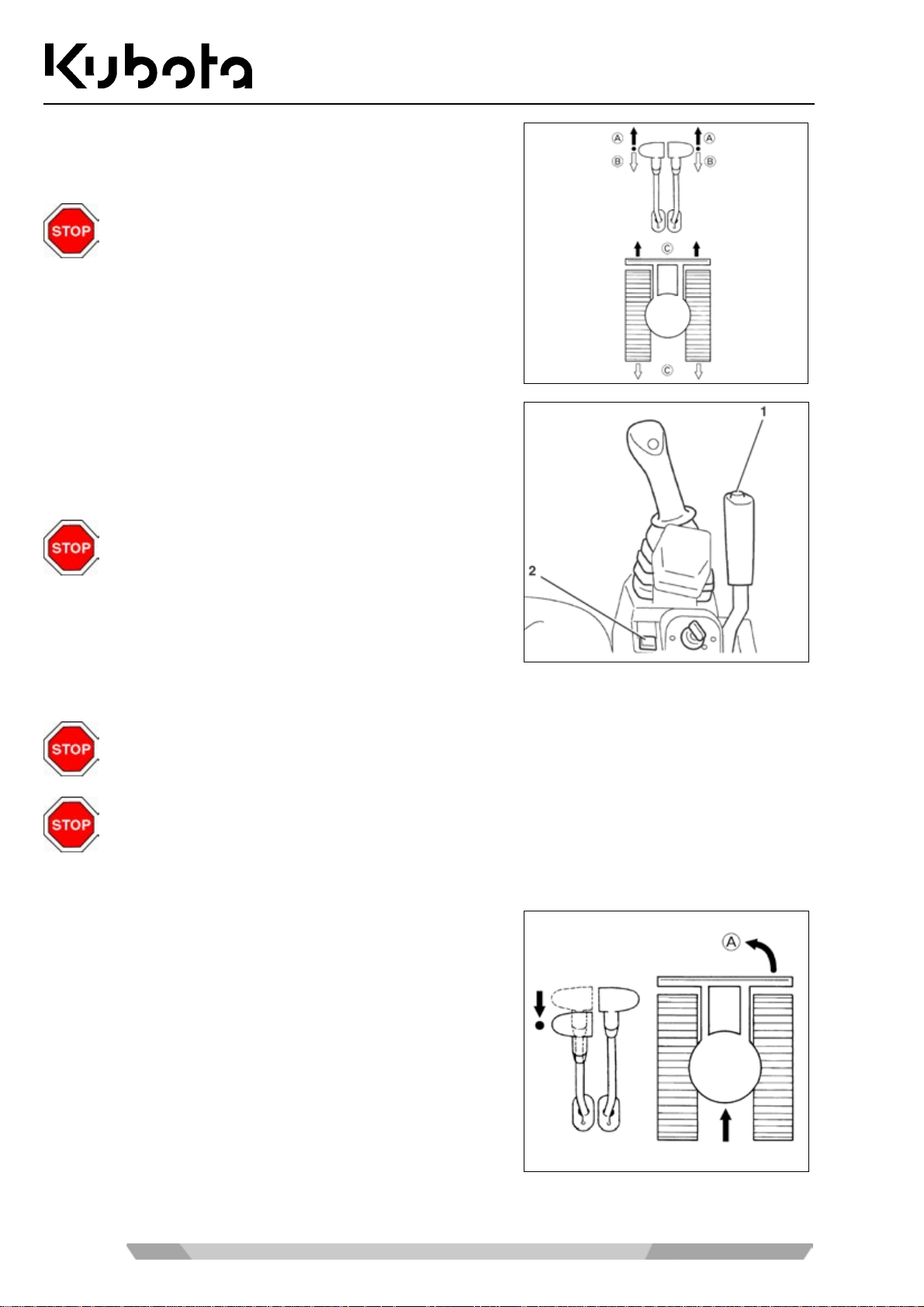
(A) Forward
(B) Reverse
(C) Straight
If the dozer is not at the front, as shown in the
figure, but at the rear, the operation of the drive
levers is exactly opposite. Drive levers forward →
the excavator drives backwards.
• To drive faster, press the travel speed button (1).
• An audible signal sounds and the indicator (2) comes up.
Pressing the travel speed button again switches back to
normal speed.
Do not drive fast on mu ddy or uneven terrain, a lso
if another control is operated (e.g. turning the
swivel frame).
Operation
Turning
Turns are described for the forward direction of trave l with the dozer at the front. If the do zer is
positioned at the rear, the steering movements should be in the opposite direction.
When making turns, be sure nobody is standing within the swing area of the excavator.
During driving
• Pul l the left drive le ver to neutral, le ave the right drive lever
pushed forward.
(A) The excavator makes a left turn.
60
Page 61
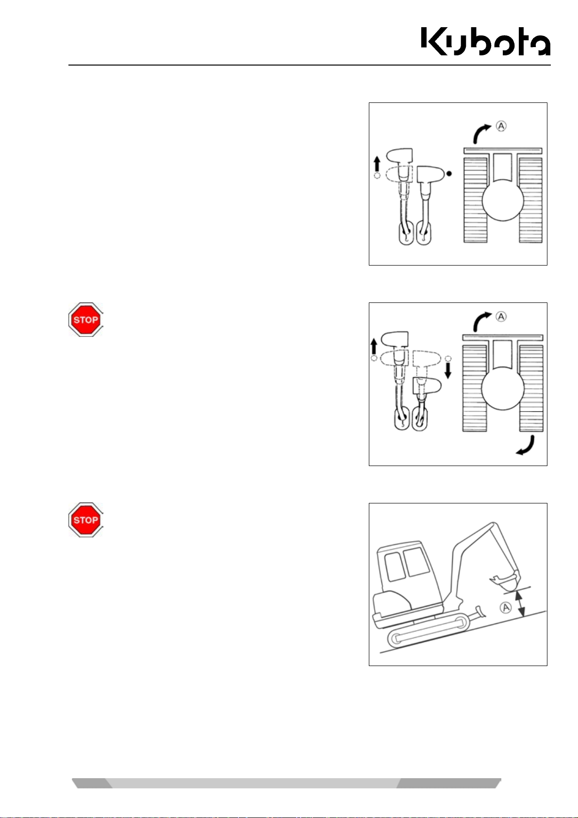
Operation
From a standing position
• Leave the right drive lever in neutral, push the left drive
lever forward. In this c ase, the turning radius is determ ined
by the right track.
(A) The excavator makes a right turn.
Turning on the spot
Do not make a turn on the spot with the travel
speed button actuated.
• Move the drive levers in opposite directions. The tracks will
turn in opposite directions. The centre of the vehicle is its
vertical axis.
(A) Turning on the spot to the right.
Driving uphill and downhill
Exercise extreme caution when driving up and
down a slope. Do not use the travel speed button.
• W hen driving on gradients, raise the buck et approx. 200 to
400 mm (A) above the ground (see figure).
61
Page 62
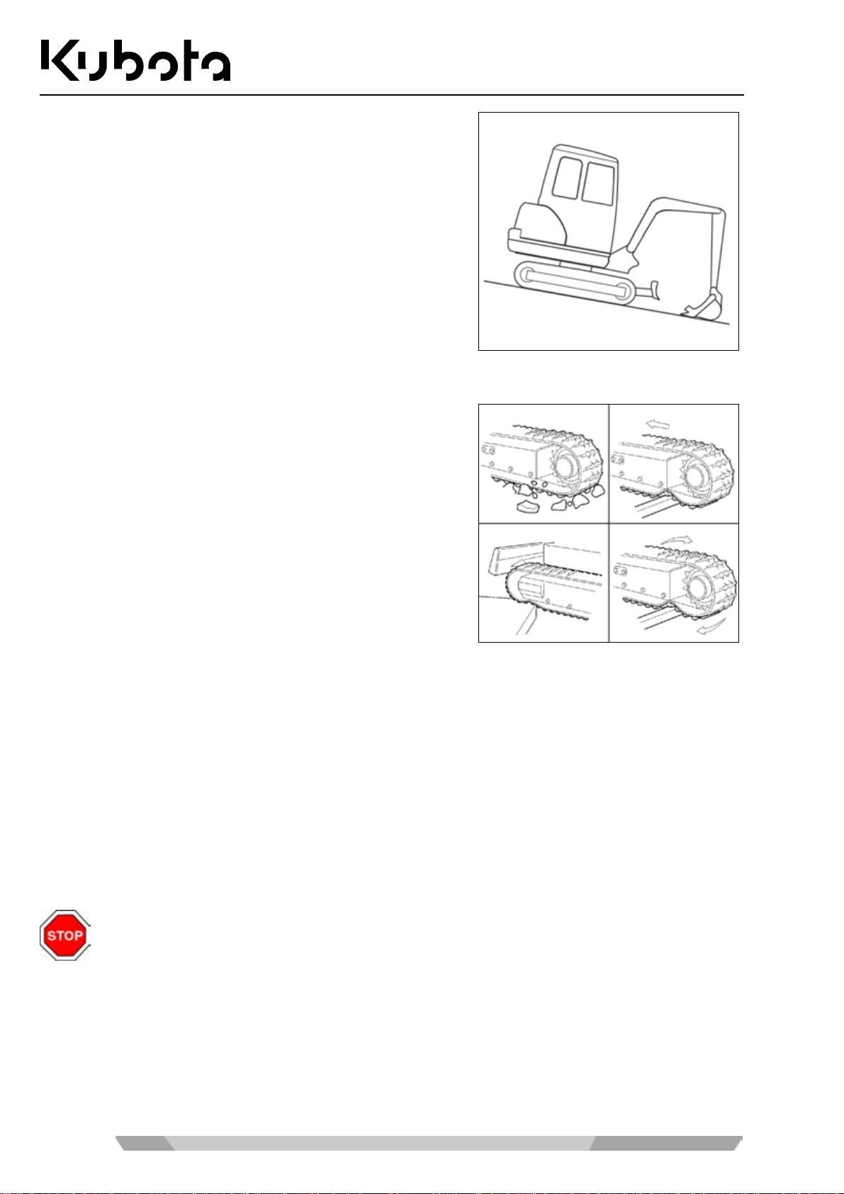
• When driving on gradients, let the bucket slide over the
ground if the terrain allows it.
Notes for rubber crawler operation
Operation
• Driving or turning on sharp objects or over steps causes
excessive wear on the rubber crawlers and will lead to
breaking of the ru bber crawler or cause the crawler r unning
surface and the steel inserts to be cut.
• Make sure that no foreign objects get stuck in the rubber
crawler. Foreign objec ts le ad to ex cess ive cra wler we ar and
can cause it to break.
• Keep oil products away from the rubber crawlers.
• Remove any fuel or hydraulic oil spilled on the rubber crawlers.
Making sharp turns
• On streets with a high-friction tarmac, e.g. concrete, do not make sharp turns.
Protecting the crawler against salt
• Do not work with the machine on the seashore. (The salt will cause the steel insert to corrode.)
Operating the controls during excavation work
Always observe the following safety instructions when working with the excavator.
• Never crush concrete or boulders using side boom swings with the bucket.
• Do not use the dropping action of the bucket for excavation.
• Never fully extend the c ylinders. Always keep a cer tain safety margin, especially when operating with a
62
breaker (accessory).
Page 63
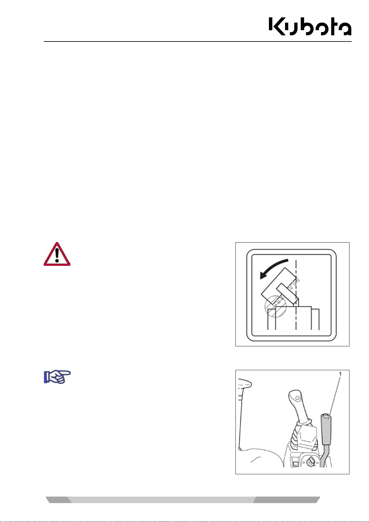
Operation
• Never use the bucket as a hammer to drive posts into the ground.
• Do not drive or dig with the bucket teeth rammed into the ground.
• When loading soil, do not dig the buck et deeply into the ground. Instead, make relativel y shallow slices
with the bucket out as far as possible. This technique reduces the stress on the bucket.
• When working in water, the water should only reach up the lower edge of the swivel frame.
• After using the machine in water, a lways grease the pins at the bucket and arm with grease until the old
lubricating grease emerges.
• W hen digging with the boom above the dozer, m ake sure that the boom c ylinder does not come into con -
tact with the dozer.
• It is f orbidden to use the e xcavator for lifting operations, unles s it is equipped with a pipe safety val ve for
crane operation (accessories) according to EN 474-5.
• Adhering soil can be sh ak en off when the buck et is being emptied by movi ng the c ylinder to the end of the
stroke. Should this not suffice, swing out the arm as far as possible and operate the bucket back and forth.
• When excavating, always lower the dozer completely onto the ground.
Notes for using wider and deeper buckets
When using a wider or deeper bucket take care
when swinging or pulling in the front attachments
that the bucket does not hit the cabin or the canopy.
Operating the dozer blade
When working with the dozer blade, operate both
drive levers with the l eft hand an d the dozer c ontrol
lever with the right hand.
• To lift the dozer blade, pull the dozer control lever (1) back.
• To lower the dozer b lade, push the dozer control le ver (1)
forward.
63
Page 64
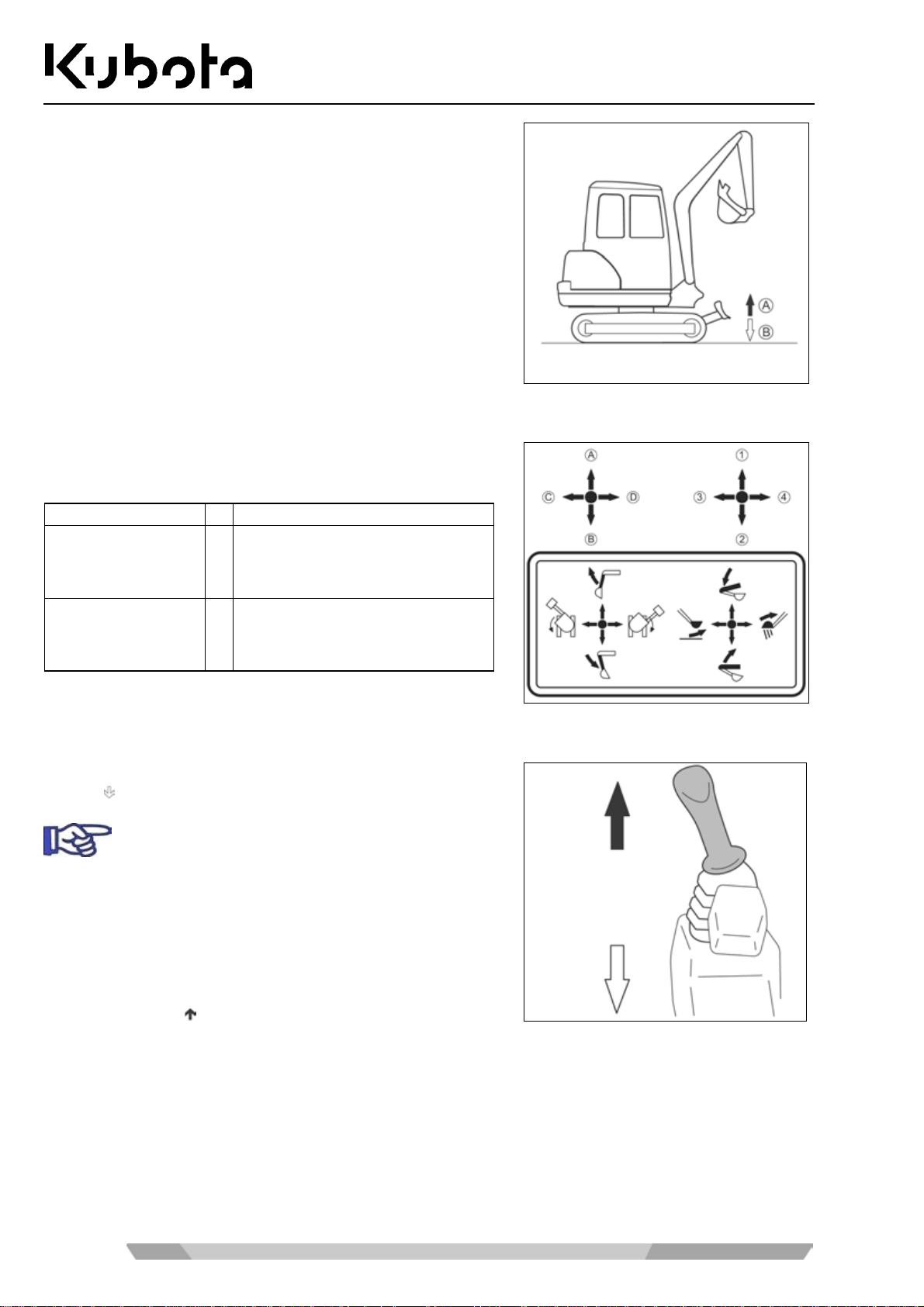
(A) Dozer blade up.
(B) Dozer blade down.
Overview of control lever functions
Operation
The figure shows, in connection with the following table, the
functions of the left and right control levers.
Control levers
Right control lever 1
Left control lever A
Movement
Lower boom
2
Raise boom
3
Bucket crowd
4
Bucket dump
Arm dump
B
Arm crowd
C
Swivel frame to the left
D
Swivel frame to the right
Operating the boom
• To raise th e boom, pull the right c ontrol lever (figure, pos i-
tion
) back.
The hydraulic cylin der of the bo om is eq uip ped with
a cushioning function, which prevents the excavated material in the bucket fro m falling out. When
the hydraulic system operating temperature is low,
the cushioning is delay ed for approx. 3 to 5 s. This
delay is due to the v iscosity of the hydraulic o il and
is not a malfunction.
• To lower the boom, push the right control lever forward
(figure, position
).
64
Page 65
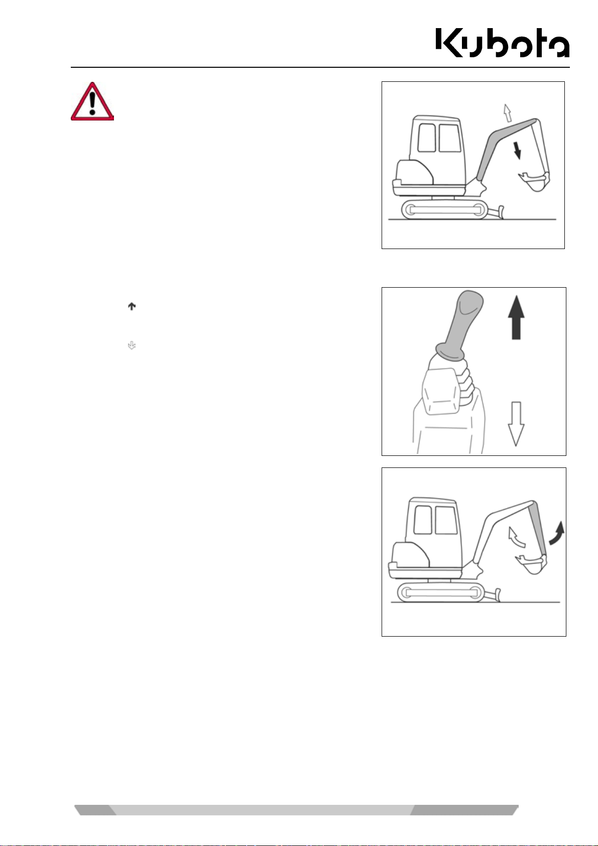
Operation
Watch the boom dur ing lowering, s o that the b oom
or the bucket teeth do not hit the dozer.
The boom moves as shown in the figure.
Operating the arm
• To dump the arm, push the left control le ver for ward (figure,
position
).
• To crowd the arm, pull the left control lever back (figure,
position
).
The arm moves as shown in the figure.
65
Page 66
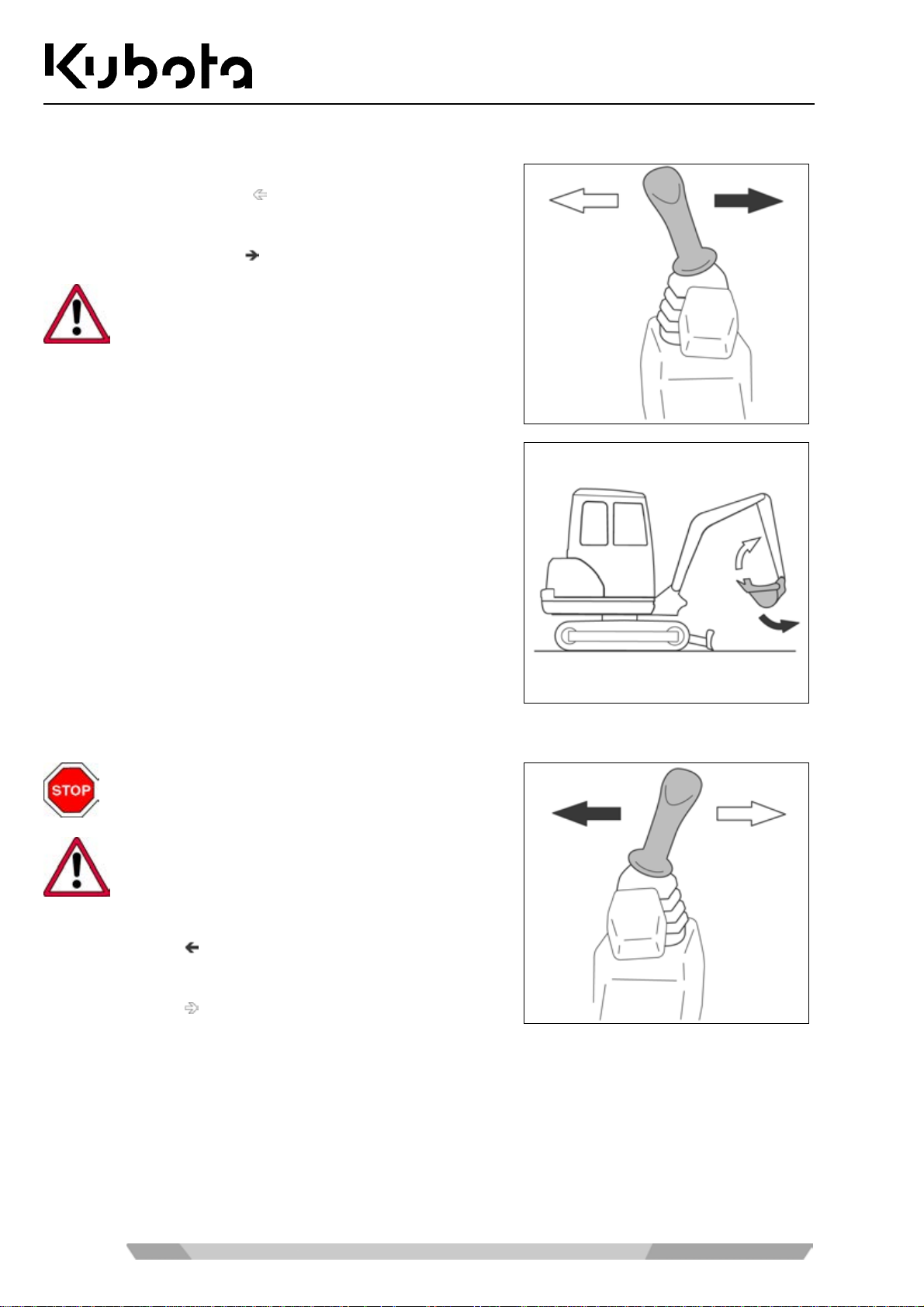
Operating the bucket
Operation
• To crowd (diggin g) the bucket, move the right contr ol lever
to the left (figure, position
).
• To dump (empty) the buck et, move t he right control lever t o
the right (figure, position
).
When crowding the bucket, take care that the t eeth
do not hit the dozer.
The bucket moves as shown in the figure.
Swivelling the swivel frame
No person is allowed to stand in the swivel area
during the movement.
Swivel carefully to avoid any contact of the front
attachments with adjacent obj ects .
• To turn anticloc kwise, move the left control lever to the left
(figure, position
• To turn clockwise, move the left control lever to the right
(figure, position
).
).
66
Page 67
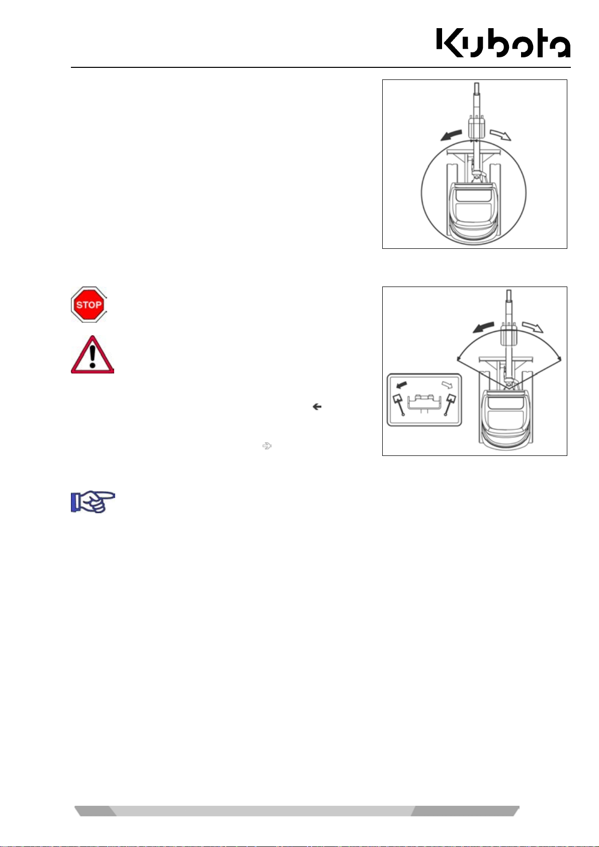
Operation
The turning operation takes place as shown in the figure.
Swinging the boom
No person is allowed to stand in the swing area
during the movement.
Swing carefully to avoid any contact of the front
attachments with adjacent obj ects .
• To swing the boom counter-clockwise, press the boom
swing pedal on the left-hand side (figure, position
).
• To s wing the boom clockwise, pres s the boom swing pedal
on the right-hand side (figure, position
).
The figure details the swing movement.
The boom swing control pedal can be secured against inadvertent operation by lowering the
locking flap. Fold the locking flap when the boom swing pedal is not in use.
67
Page 68
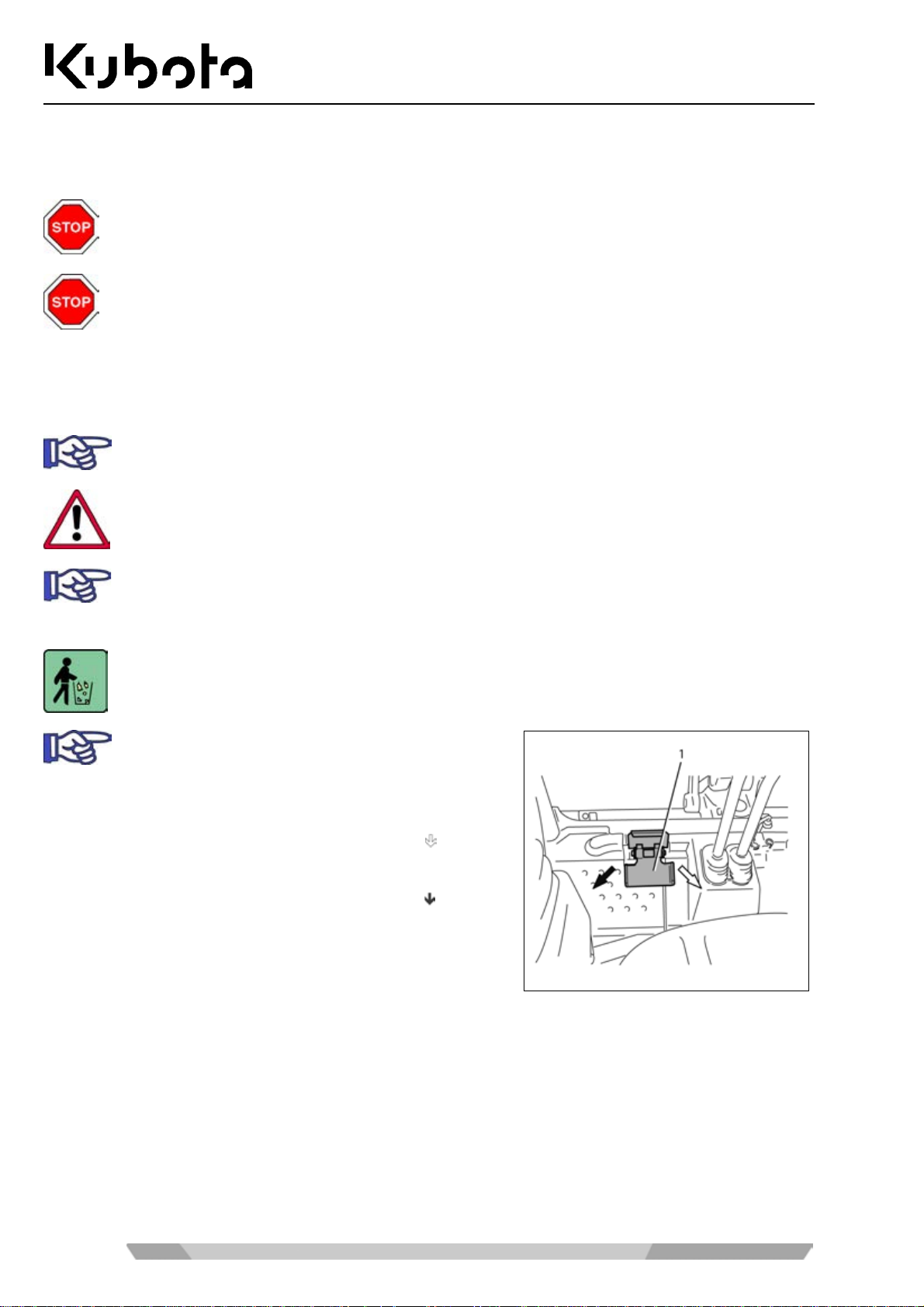
Operating the auxiliary port
Implements are operated using the auxiliary port.
Only implements approved by KUBOTA may be used. The implements must be operated in
accordance with the operating instructions supplied with them.
With the use of a breaker or another attachment for demolition work, where material (e.g. asphalt) is removed a nd can uncontrollably sputter awa y, personal protective equipmen t is absolutely to be worn (safety shoes, safety helmet, eye protection, ear protection and if necessary
facial mask). The use of a gravel guard (front protective grid) is recommended. For excav ation
work with a cab, the front window must be c losed, in addition. For demolition (ac cording to EN
474-1, Annex G), e.g. tearing down walls, the corresponding protective equipment is required
(e.g. gravel guard).
For auxiliary port specifications, see the "Specifications" section (page 35).
The auxiliary port peda l (figure below, position 1) ma y only be activated when an implem ent is
attached.
If the auxiliary port has not been in use over a lon g period of time, dirt may have ac cumulat ed on
the pipe connections . Before ins tallin g the imp lement, drain appr ox. 0.1 L of hy draul ic oil at eac h
port.
Operation
Catch the drained hydrauli c oil in a container and dis card it in accor dance with the vali d environmental regulations.
The auxiliary port pedal can be secured against
inadvertent operation by lowering the locking flap
(1). Fold the locking flap when the auxiliary port
pedal is not in use.
• Depressing the right-hand part of the pe dal (f igure/
oil pressure to the connection (figure below, position 1).
• Depressing the lef t-hand part of the pedal (f igure/
oil pressure to the connection (figure below, position 2).
) sends
) sends
68
Page 69
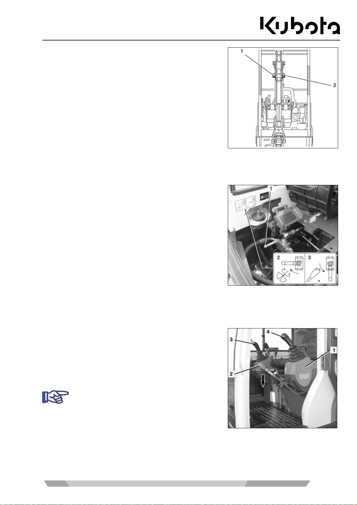
Operation
(1) Connection for right-hand part of pedal
(2) Connection for left-hand part of pedal
Return change valve
The change valve has two settings.
When the "direct return flow" (3) is enabled, the return flow is
directed from the im plement to the hydraulic oil tank. The retur n
flow is directed via the right auxiliar y port connector at the arm
only.
When the "indirec t return flow" (2) is enabled, the ret urn flow is
directed from the implement to the hydraulic oil tank via the
control valve. In that case, the return flow may use the left or
right connector of the ar m (depending on the aux il iary port pe dal
position).
Move the ball valve ( 1) to t he requir ed pos ition as sho wn on t he stick er ( see f igure), dep ending on the ac tion of
the implement being used (rotary or hammering).
Pressure relief of the hydraulic system
• Lower front attachments and dozer completely.
• Turn the starter switch to the STOP position.
• Wait until the engine has come to a standstill.
• Turn the starter switch to the RUN position.
Do not start the engine!
• Lower the left control console (1) and make sure that the
control lever lock (2) engages .
• Move control levers (3 and 4) several times to limit stop in
all directions.
The hydraulic system is pressure relieved.
69
Page 70
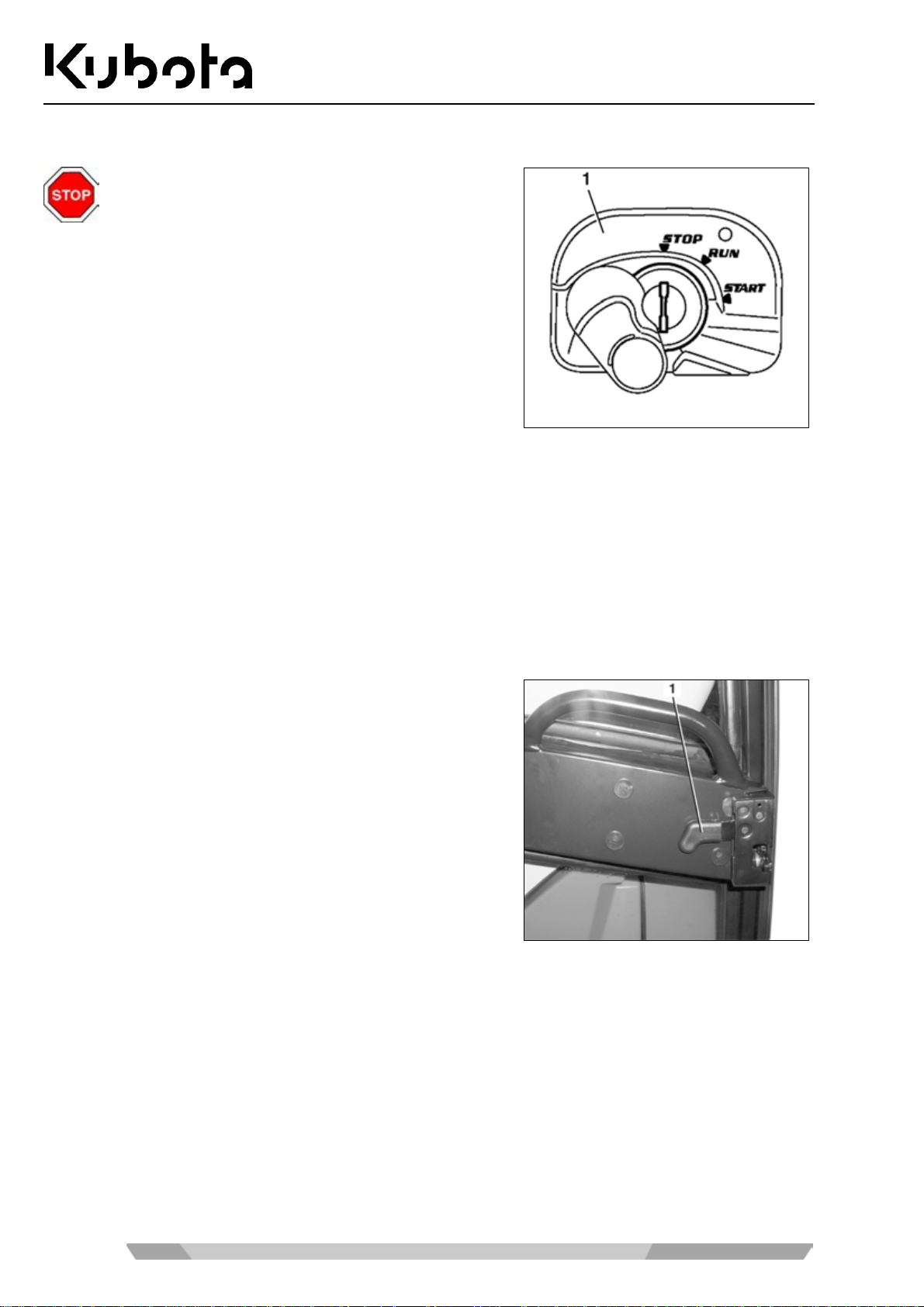
Placing out of operation
Operation
Park the excavator in such a way that it can not
move and is secured against unauthorised use.
• Drive the excavator on level ground. Non-cab models
should be parked under a roof.
• Operate the bucket, arm and boom swing mechanism so
that all hydraulic cylinders are extended half way.
• Lower the dozer onto the ground.
• Reduce the engine speed to idle speed.
• Turn the starter switch (1) to the STOP position, remove the key. The key must remain with the operator.
• Unbuckle the seat belt and raise the left control console.
• Check the excavator for external damage and for leaks. Any defects must be repaired before the next start.
• In case of a heav y accumulation of dirt in the area of the tracks and the hinges at the front attachments,
clean the excavator (page 96).
• Refuel the excavator, if necessary (page 80).
Cab version only
• Open the cab door by pul ling up r elease lever (1). If the c ab
door is not closed immediatel y, afterwards lock the door on
the cab wall.
• Close a nd lock the cab do or. The key must r emain with the
operator.
70
Page 71
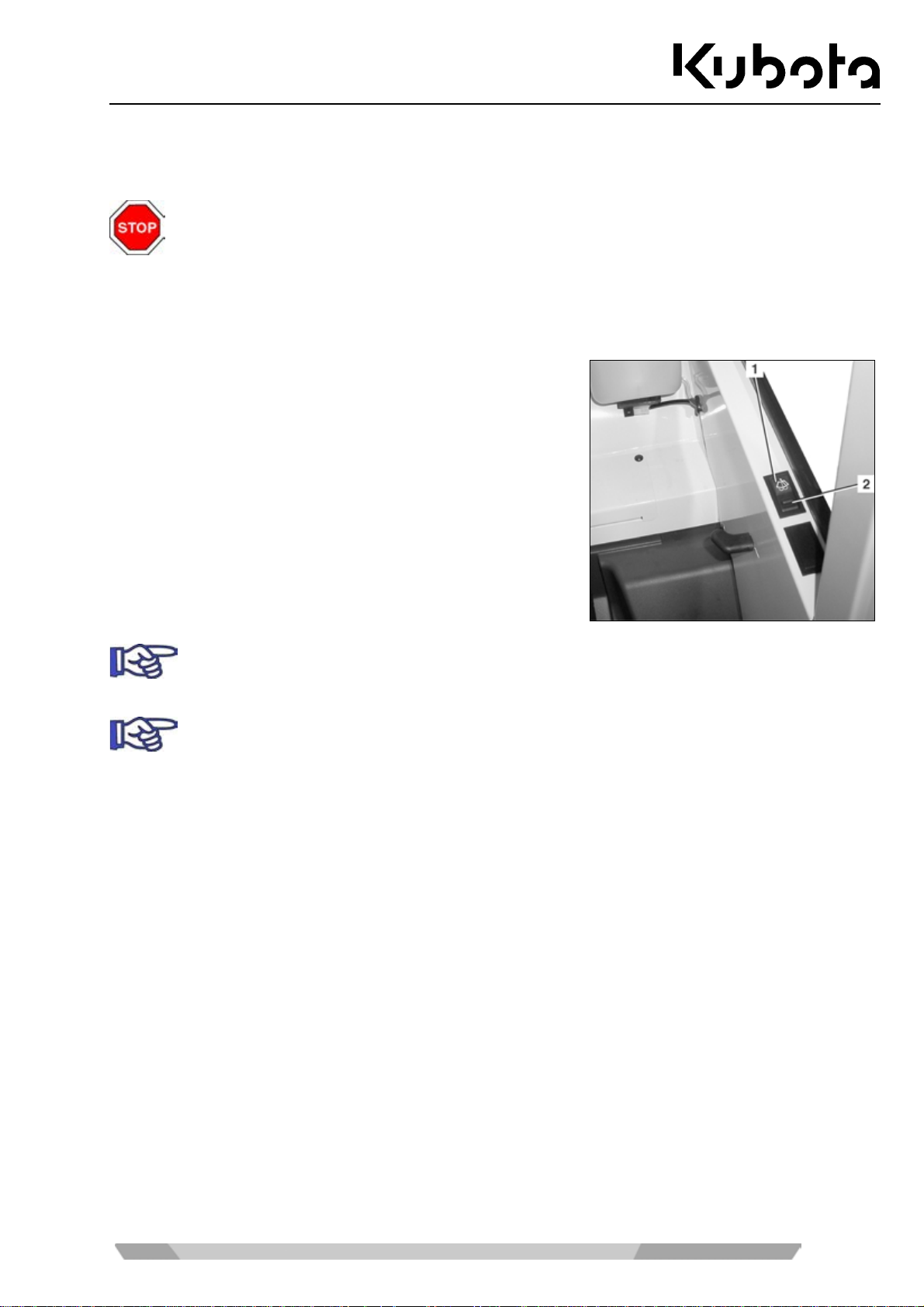
Operation
Operating the wiper/washer system
All cabin models are equipped with a wiper/washer system.
Risk of injury!
If you turn on the wiper while the w indscreen is opened, the wiper may slide off the mo unting
bracket attached to the cab frame hitting the ins ide of the cab. there is a risk of the operator’s
face being hit by the wiper.
• Do not turn on the wiper switch while the windscreen is open.
Switching on the windscreen wiper
• The starter switch is in the RUN position.
• Depres s the wiper s witch (1). The window wiper oper ates as
long as the switch rem ains in this pos ition. To turn the wiper
off, press the switch in the opposite direction.
In extremely cold weather conditions, make sure the wiper rubber does not stick to the w indow.
This may damage the wiper rubber or the wiper motor.
Only switch on the wiper when the window glass is wet. If necessary, switch on the washer system first.
Switching on the washer system
• The washer system is switched on. Press and hold t he switch on the second level. T he washer system
operates as long as the swit ch rem ains depres sed. When the switch is releas ed, it r eturns autom atical l y to
the "wiper" position.
• To switch on the washer system only, press the switch down to the OFF position. The washer system
operates as long as the switch remains depressed.
71
Page 72
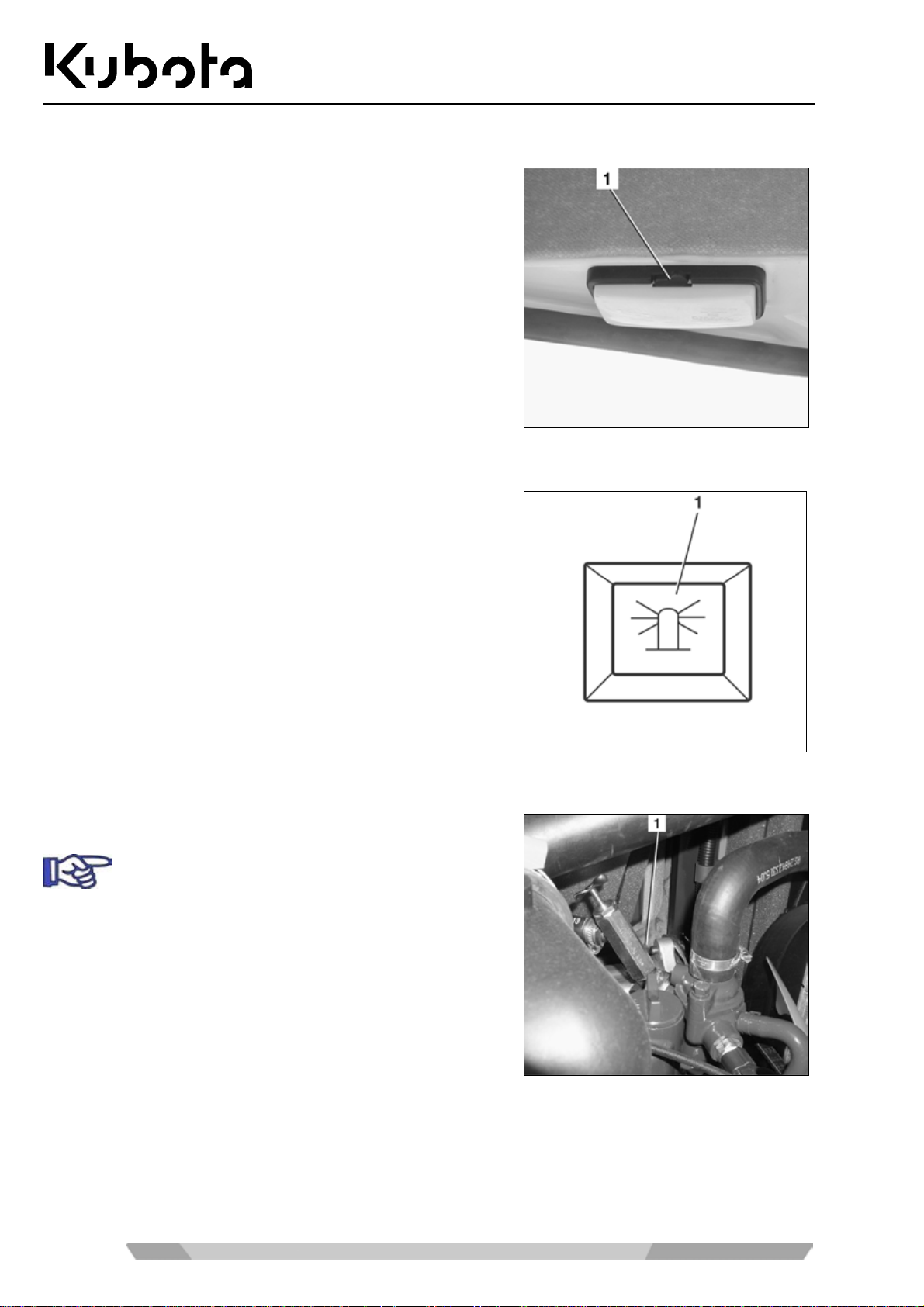
Operating the room light (cab version)
Operation
• The starter switch is in the RUN position.
• To turn the light on, depres s the togg le switch (1). T o turn it
off, press the switch in the opposite direction.
Operating the rotary beacon (accessories)
• The starter switch is in the RUN position.
• Press the rotary beacon b utton (1). Press the button again
to switch the beacon off.
Operating the heater (cab version)
• Open the heater valve (1) by turning it anticlockwise.
In summer, the heater valve s hould always be kept
closed.
72
Page 73
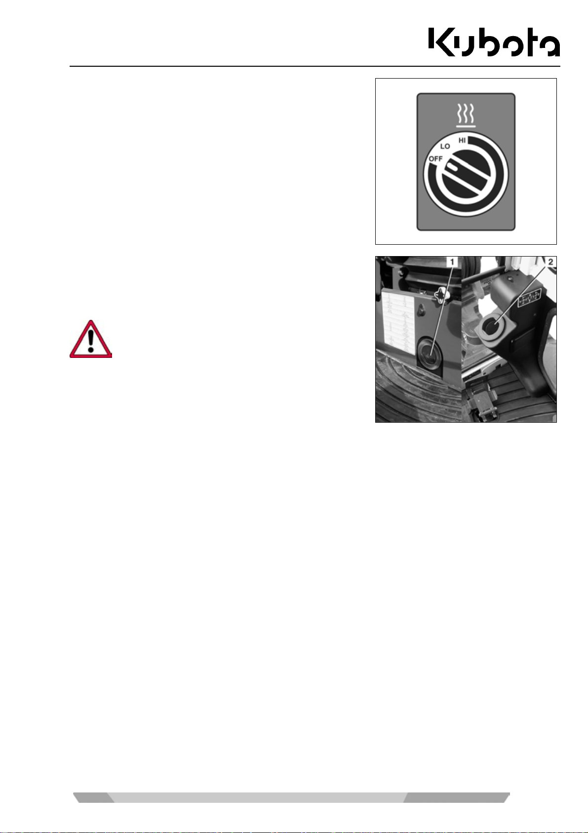
Operation
• The starter switch is in the RUN position.
• Turn the blower switch to the LO or HI position.
• When the engine is at operating temper ature, the heater air
flows out at the air outlets under the oper ator's seat (1) and
at the front windo w (2). The directio n of the air flow c an be
adjusted.
In order to avoid a heat backup and therefor e damage to the ventilation system, do not cover the
outlets with objects (e.g. bags or clothin g) wh en the
heater is in operation.
73
Page 74
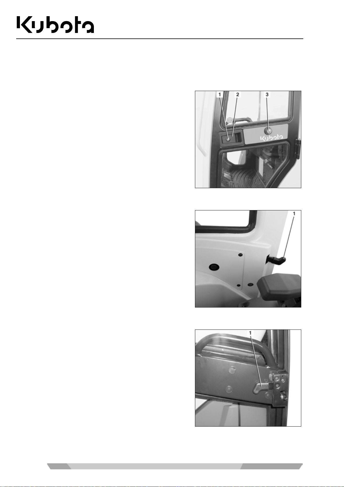
Opening and closing the cab door
For cab versions, read the following instructions for opening and closing the cab door.
Opening the cab door from outside
Operation
Unlock the cab door at the door lock (1).
Open the cab door b y pulli ng at th e door hand le (2) and l ock the
door by attaching the hook (3) at the fixture on the cab wall.
Closing the cab door
• Pull the release lever (1) and pull the cab door into the lock.
Opening the cab door from inside
• Pull up the release lever (1) and ope n the door. If the cab
door is not closed immediatel y, afterwards lock the door on
the cab wall.
74
Page 75
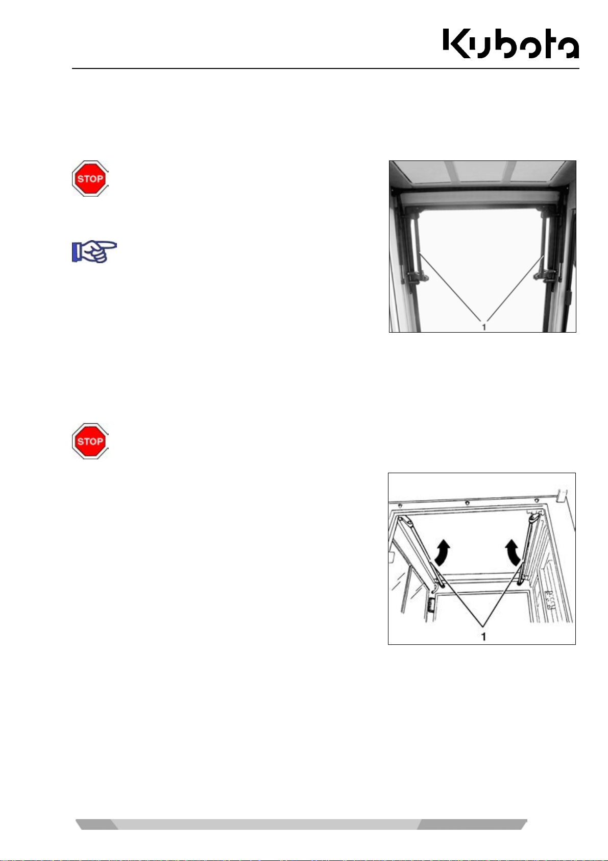
Operation
Opening and closing the windows
For cab versions, read the following instructions for opening and closing the front and side windows.
Front window
Always lock the front window. Do not stay in the cab
and operate the excavator with the front window
unlocked. When opening t he window, always keep
both hands on the lock bars to prevent injury by
pinching or crushing.
The front window can be opened a nd closed from
the operator's seat.
Opening
• Press the right and left lev ers (f igure above, pos ition 1) inwards s imultaneo usly and pus h the front windo w
upward in the guide rails as f ar as the stopper. L ock the front window at the stopper by rele asing the le vers. Check that the front window is locked.
Do not release the lever s p ushing th e fron t wind ow up as the front wi ndow c ould s uddenly rise in
an uncontrolled way and str ike the operator's head. Please follow the safety instructions on the
side window.
Closing
• Press the right and left levers (1) inwards simultaneously
and push the front window forward in the guide rails as f ar
as the stopper. Lock the front window at the stopper by releasing the levers. Check that the front window is locked.
75
Page 76
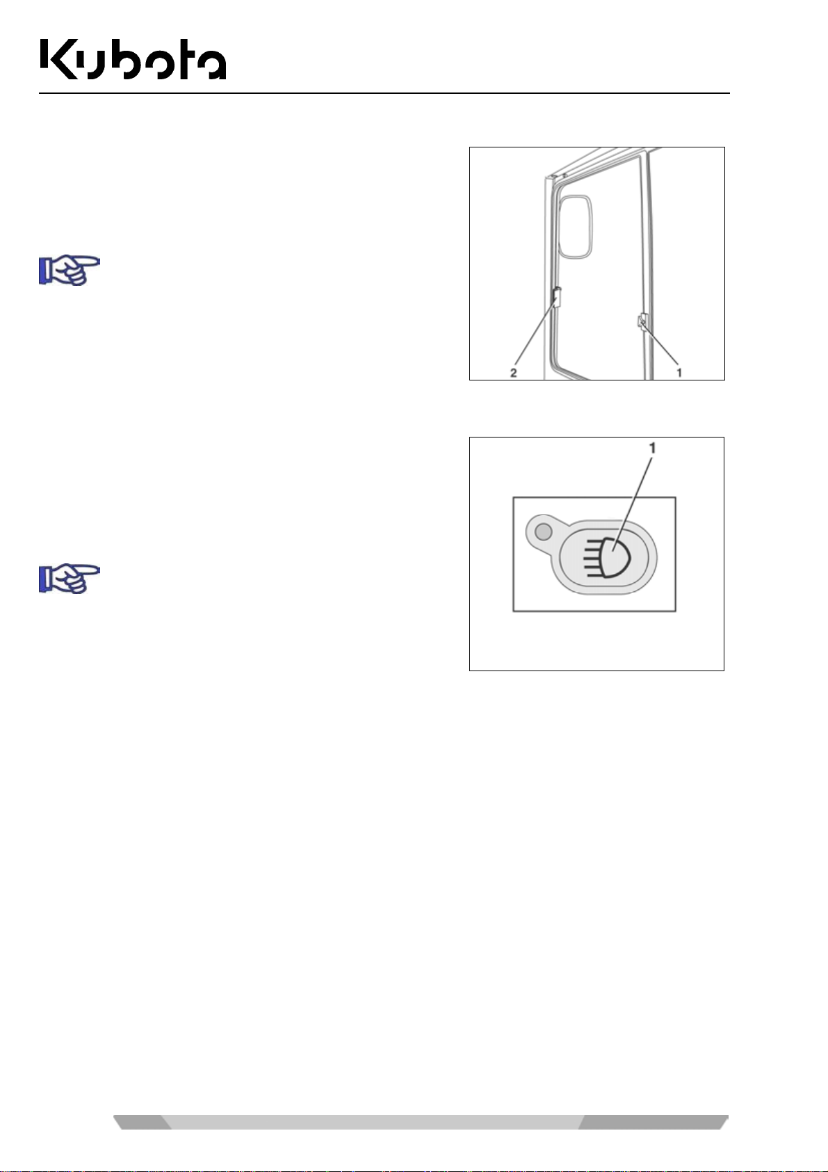
Side window
Operation
• Pull the grip (2) to release t he loc k and pull the s ide wi ndow
open to the rear.
• To close the side window, slide it forward until the lock
engages at the window frame.
The side window can be fix ed to any pos ition using
the locking screw (1).
Operating the working lights
• The starter switch is in the RUN position.
• Press the working light button (1). Both the working lights
and the instrument lighting are turned on.
• Press the button again to switch off.
During work on public road s other road users must
not be blinded.
76
Page 77

Operation
Cold weather operation
Operating the excavator at an ambient temperature below 5 °C is regarded as cold weather operation.
Necessary preparations prior to the winter season
• If necessary, replace the engine oil and hydraulic oil with those of the viscosities specified for winter.
• Only use regular diesel fuel with winter additives. Do not mix petrol and diesel fuel.
• Check the battery's state of charge. In cas e of ex tremely low tem peratures , it m ay be necess ary to rem ove
the battery after work and store it in a heated room.
• Check the antifreeze streng th in th e c ool ing system (page 96). If necess ary, add antifreeze until the protec -
tion ranges from -25 °C to -40 °C.
• Apply talcum powder or silicone oil to all r ubber seals at the windows, th e cab door and the side windo w
guide rails.
• Lubricate all locks, except the starter switch, with graphite lubricant.
• Grease the cab door hinges.
• Fill the washer system with a antifreeze window cleaner (page 79).
Operation during the winter season
• The excavator must be cleaned after work is finished (page 96). Special attention must be paid to the
crawlers, the front attachm ents and the piston rods of the hydraulic cylinders. If the excavator is clean ed
with a water jet, it must then be parked in a dry, frost-free and well-ventilated enclosed space.
• If necessary, park the excavator on boards or mats in order to prevent freezing to the ground.
• Before starting, c heck if the piston rods of the hydraulic cylinders are free of ice to avoid damage. Also
check if the crawlers are frozen to the ground. If so, do not take the excavator into operation.
Be careful when getting on and off, the crawler could be slippery.
• Do not put a load on the excavator immediately after starting. Before you start working with the front at-
tachments, warm up th e excavator until th e op erat ing temperature is r each ed. Do not warm up the excavator at idling position
77
Page 78
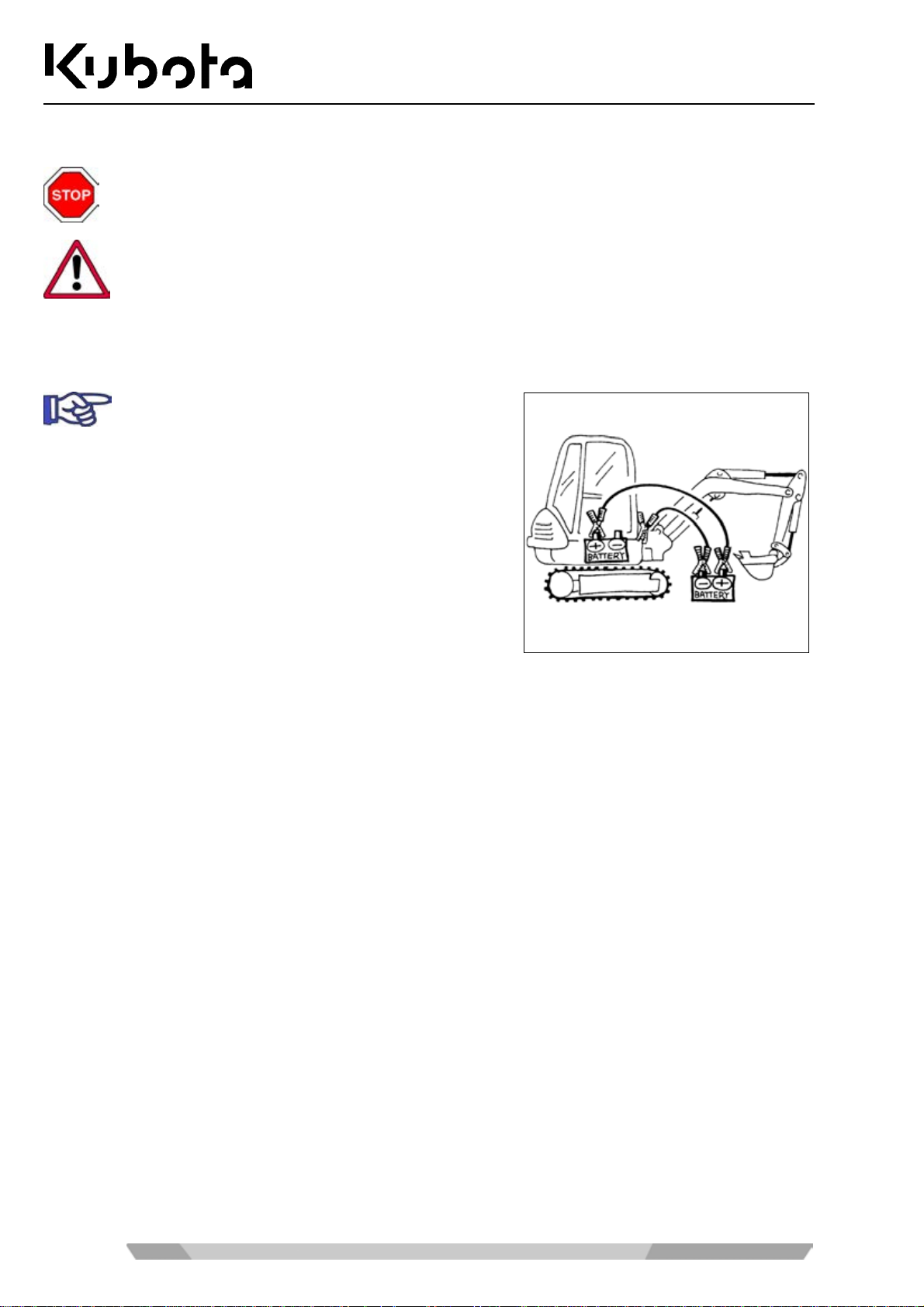
Jump-starting the excavator
Only a vehicle or starting device with a 12V power supply may be used.
• Make the battery accessible, and remove the positive terminal cover.
• Position the other vehicle or starting machine beside the excavator.
• Connect the positive term inal of the excavator battery with
• Connect the negat ive terminal of the he lping vehicle to the
The operator must remain seated on the operator's place, the battery jumper cables must be
connected by a second person.
Only use cables with an appropriate cross section
as jumper cables.
the positive terminal of the helping vehicle (see figure).
frame of the excavator. Do not use the ne gative term inal of
the excavator battery. The connecting point on the frame
must be blank and clean.
Operation
• Start the helping vehicle and let it run at a higher idle speed.
• Start the excavator and let it run. Check if the charge lamp turns off after starting.
• Disconnect the jum per cable at the frame of the exc avator first, and then at the nega tive terminal of the
helping vehicle.
• Disconnect the second j umper c able f rom the pos itive term inal of the ex ca vator b atter y first, an d t hen f rom
the positive terminal of the helping vehicle.
• Refit the positive terminal cover on the excavator battery and install the cover and rubber mat.
• If the j umper cables will be required f or the next start of the ex cavator, check the batter y and the alterna-
tor's charging circuit, contact skilled personnel, if necessary.
78
Page 79
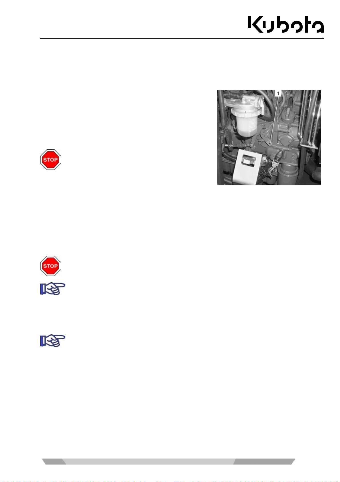
Operation
Emergency stop functions
In case of emergency, you can switch off the engine and lower the boom manually.
Manual engine stop
If the engine cannot b e stopped with the k ey, it can be stopped
manually.
• Open the engine compartment cover (page 82).
• To stop the engine, push lever (1) to the left unt il the e ngine
stops.
The excavator may on ly be taken back into operation after the malfunction has been eliminated.
Manual lowering of the front attachments
The boom and arm can be lowered in case of an engine failure or if malfunctions occur in the hydraulic system.
• The starter switch is in the RUN position.
• If necessary, lower the boom and the arm with the c ontr ol lever as des cribed i n the "O peratin g the co ntrols
during excavation work" section (page 62).
Make sure nobody is s tanding in the lowering area b efore starting the emer gency lowering procedure.
The lowering functio n is available only for a short tim e, as it is control led by the accumulator in
the hydrauli c system. The cylinders extend or retract by force of gravity.
Filling up the washer system
• Open the washer system reservoir and add water or a cleaning agent.
In winter, use a cleaning agent with antifreeze.
79
Page 80
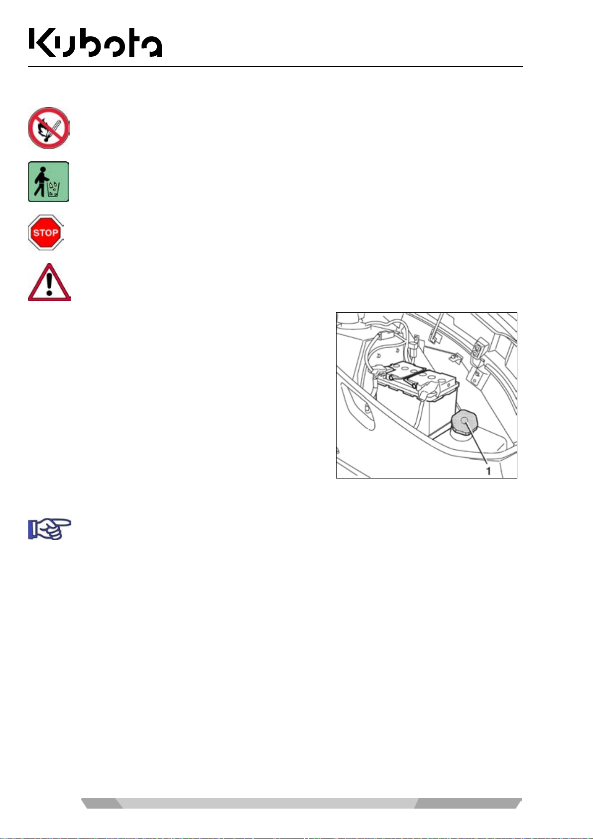
Refuelling the excavator
When refuelling the excav ator, smoking, an open flame, or other sources of ignition are not allowed. The danger zon e must be marked wi th signs. A fire ex tinguisher must be kept at hand in
the danger zone.
• Stop the engine.
• Open the side cover (page 83).
• Remove the filler cap (1) by swivelling it anticlockwise.
• Fill diesel fuel up to the base of the filler tube.
• Refit the filler cap and close the side cover.
Spilled fuel must be bo und immediately with an oil b inding agent. The contamin ated oil binding
agent must be disposed of in accordance with the applicable environmental regulations.
If no pumping station is available, the diesel fuel may only be stored in approved canisters.
Refuel the excavator in time so that the fuel ta nk is not running empty. Air in the fuel system can
damage the fuel injection pump.
Operation
Bleeding the fuel system
If the excavator fuel tank was run empty or the water separator was cleaned, the fuel system
must be bled.
• T o bleed the fuel s ystem, m ove the starter switch to the RUN positi on. The electr ical fuel pump will bleed
the fuel system automatically within approx. 60 s.
• If the bleeding was insufficient, the engine will stop again. In this case repeat the procedure.
80
Page 81

Operation
Replacing the fuses
Defective fuses may only be replaced with fuses of the same type and same rating.
The bypassing of fuses, for example by a wire, is not allowed.
If the malfunction can not b e remedied by replacing
the fuse, or if the fuse blows again when starting,
contact skilled personnel.
The fuse layout of the fuse box with their rating is
indicated on the cover (1) below the operator's
seat.
The excavator's main fuse is positioned next to the battery, and the alternator circuit fuse is
mounted in the engine compartment in front of the alternator.
• Unlock the cover (figure above, position 1) and lower it down.
• Remove the defective fuse from the fuse box (1) and re-
place it.
• The fuse layout is shown in the next figure.
• The main fuse (3) is positioned above the battery and th e
alternator circuit fuse (2) beside the fuse box.
81
Page 82
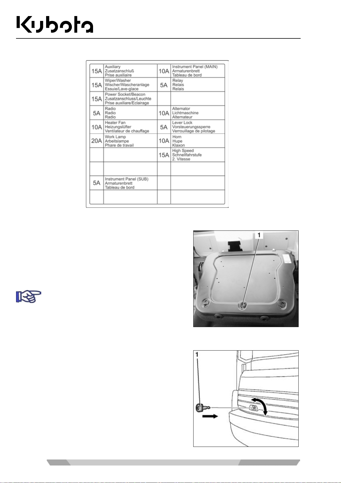
Fuse layout of the fuse box
Operation
Installing and uninstalling the operator's seat
The seat cushions can be rem oved for cleaning or repl acement.
The backrest is given as an example.
• Fold the backrest forward.
• Open the clips (1) and swivel them so that the clips go
through the backrest. Remove the backrest cushion.
The backrest can be cleaned with suds.
Opening and closing the engine compartment cover
• Insert the key (1) in the lock of the engine compartment
cover, turn it anti-clockwise, then depress the lock.
• Open the engine compartment cover and lift it up. The
engine compar tm ent c over wil l s tay in the open pos it io n du e
to the stay.
• To close the engine c ompartment cover, depress the lock .
Insert the key into the lock and turn clockwise to lock the
engine compartment cover.
82
Page 83
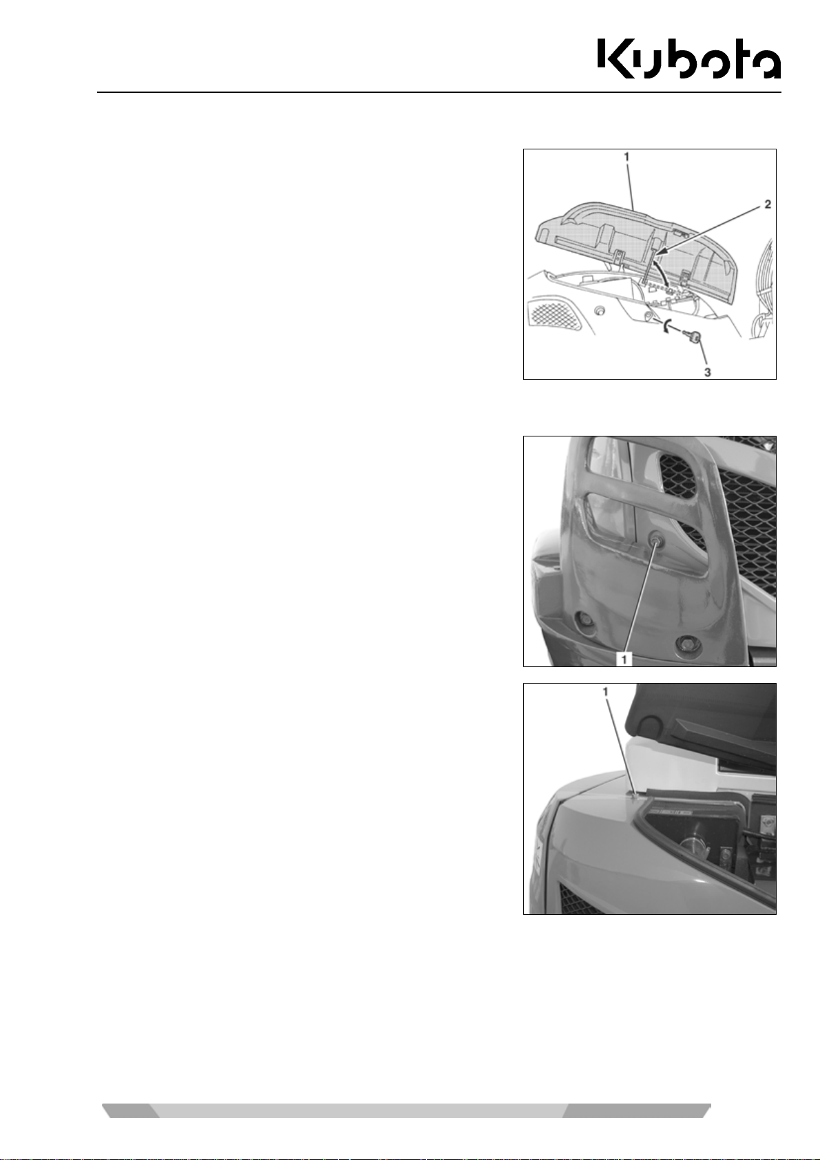
Operation
Opening and closing the side cover
• Insert the key (3) in the lock of the side cover, turn it anti-
clockwise, then depress the lock.
• Open the side cover (1) and lift it. Secure the side cover
with the stay (2).
• To close, depress the side cover into the lock and lock it
with the key.
Removing and installing the right side panel
• Open the side cover (page 83).
• Remove the mounting screw (1) from the side panel.
• Remove the mounting screw (1).
83
Page 84
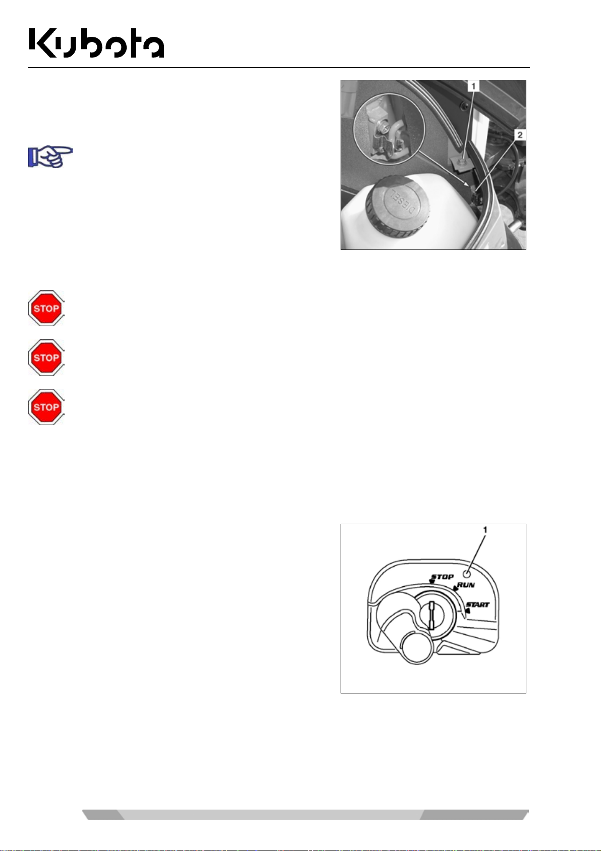
• Remove the mounting screw (1).
• Pull the side panel from the mounting (2) and remove it
from the excavator.
For installation first press the side panel into the
mounting and reinstall all the screws.
Replacing the bucket
When replacing the bucket, make sure to wear an eye protection, a helmet and protective gloves.
Operation
During attaching and detac hing, chippings and burrs may occur at the bolts or bushings. T hese
may cause severe injuries.
Never use your fing ers for the a lignment of the c omponents ( link, buc ket, arm) . The com ponents
may sever your fingers by uncontrolled movements.
Anti-theft system
The excavator is equ ipped with an anti-theft system that restricts the engine to be started using a registered
key only. If a registered k ey gets lost or stolen, you can invalid ate it. This will prevent the engine f rom being
started with this k e y, thus p r otectin g the vehicle agains t thef t. The anti-theft system makes it difficult to st ea l the
machine. However, it can not fully prevent theft.
If the starter switch is set to STOP, the indica tor light (1) is illuminated, indicating the activation of the anti-theft system.
Make sure that the indic ato r light is i lluminat ed when l eaving the
machine.
The vehicle comes with two different types of key:
84
Page 85
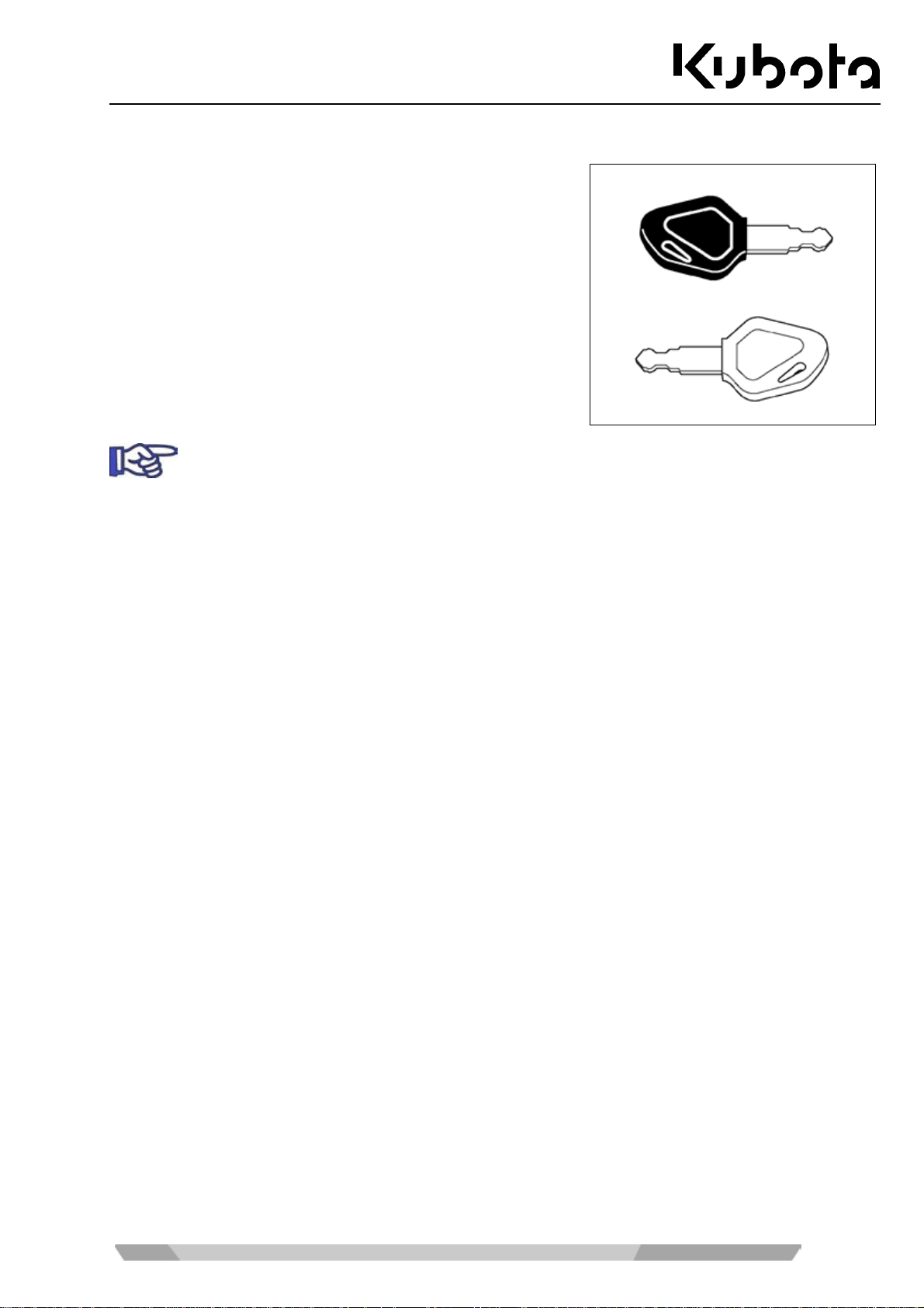
Operation
Black (individual) key
• This key is used to start the engine.
• The engine can be started b y inser tin g the key and turning it
to the START position.
• To be able to start th e engine with a black k ey, it must be
registered using the red key.
The engine can be started only with a key that was registered for the particular vehicle.
The scope of delivery includes two black keys, among them a spare key. The two black keys
have already been registered. Up to four keys can be registered.
Red key (for registering)
• If one of the black keys is lost, another black key can be registered using the red key (page 86).
• The engine can not be started with the red key.
The key system
• If a register ed key is lost, the second and new black key must be re-registered. T his procedure locks the
lost or stolen black key, which can no longer be used to start the engine.
• If the red key is lost, the b lack keys can no longer be re- regis ter e d. B e sur e to keep the red key in a secure
location (such as a saf e in the office). Never lea ve the key inside the m achine. If it should get l ost nevertheless, please contact your authorised dealer immediately.
• If six times attempts are made within one m inute to turn the starter switch to t he START position with a
wrong or unregistered k ey, an acoust ic signal will s ound for 30 seconds. The s ignal will cont inue to sound
even if the starter s witc h is tur ned t o th e STOP position aga in or the key is removed withi n th is time period.
When a key register ed f or t his m achine is i nserted into the s tarter s witc h, the aco ustic s ignal will b e tur ned
off.
• Do not use several of these keys in a bunch. This could lead to electrical interfering frequencies which
might prevent the motor from starting.
• Use only the special KUB OTA key ring. Other key rings can lead to s ignal failures between the key and
starter switch, and the engine can possibly not start or a key registration cannot be performed.
• After receiving the set of keys, separa te them from eac h other. Always m ake sure the ke ys are not part of
a bunch. If one of th e black keys, for exam ple, is inser ted into the st arter switch, the red ke y might be detected by the electronic system. This might lead to a failure of the electronic system.
• If machine m alfunctions occur, please co ntact your Kubota dealer imm ediately in order to have the mal-
function localised and rem edied.
• Messages in the display can be shown in 11 languages.
Your KUBOTA dealer can assist you in your language selection.
85
Page 86
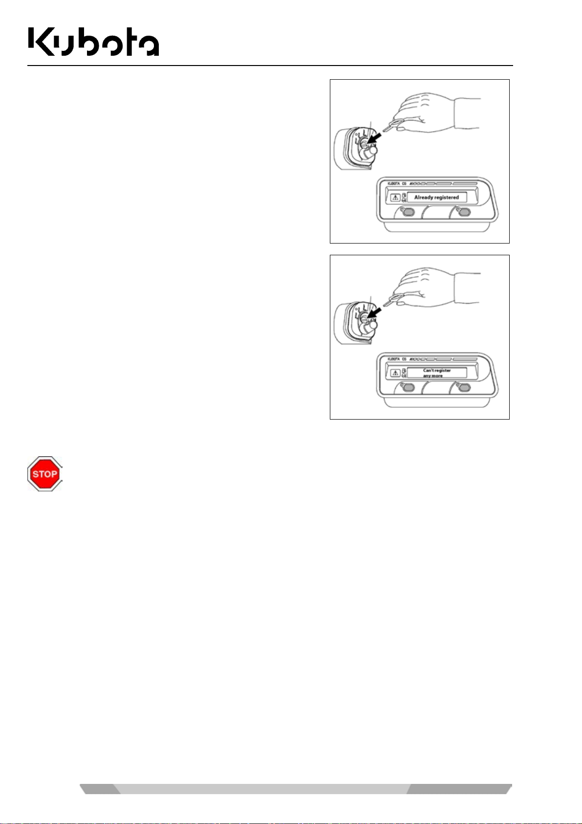
• If you erroneously attempt to register a blac k key that has
already been register ed, the display will show the " Already
registered" message. This means that registration can not
be done.
• If you attempt to register a fifth black key, the display will
show the "Can't register any more" message. This means
that the registration can not be done.
Operation
Registering a black key for the machine
Register a black key only under the following conditions:
Make sure that there are no pers ons within the excavator's wor king area. It is essential to warn
persons in the vicinity of the excavator by briefly honking the horn.
Make sure that all operational controls are in neutral position.
Starting the excavator is only allowed when the operator is sitting on the operator's seat.
Do not allow the engine to run ind oors, unless the room is equippe d with an exhaust gas extraction system or otherwise well ventilated. The exhaust gas conta ins carbon monoxide, a colourless, odourless and fatal gas.
86
Page 87
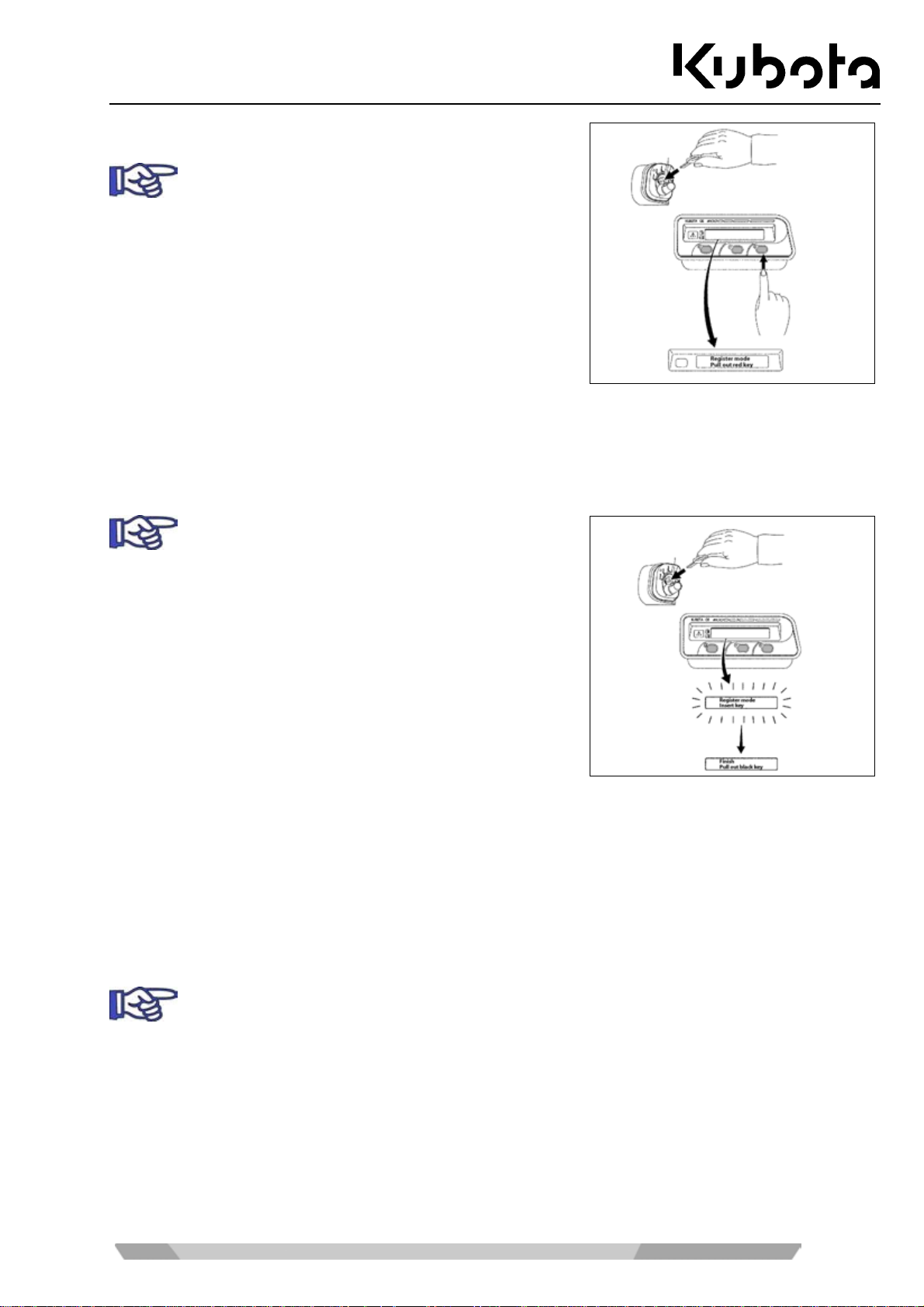
Operation
1. Insert red key into the starter switch.
Do not turn the key at this point. If the key is i n the
RUN position, turn it back to the STOP position.
2. Press the display selector switch.
3. The display shows the "Register mode – pull out red key"
message.
4. Pull out the red key.
5. The display shows the "Register mode – insert key" message.
6. Insert black key into the starter switch.
Do not turn the key at this point. If the key is i n the
RUN position, turn it back to the STOP position.
7. T he displa y sho ws the blin k ing "Regis ter m ode – inser t ke y"
message.
8. After a brief moment, the display shows the "F inish – pull
out black key" message. This message indicates that the
black key was registered for the given vehicle.
9. O nce the b lack ke y is pulle d ou t of th e start er s witch, the d ispla y will s how th e "F inish – pul l out black k ey"
message.
Follow steps 5 to 8 to register a spare key. Up to four black keys can be registered.
10. Turn the key to the RUN position to finish the registration procedure.
11. One after the other, insert all registered black k eys into the starter switch and check whether the engine
can be started using these keys.
If a registered black key is lost, the other black keys must be re-registered. This procedure locks
the lost or stolen black key, which can no longer be used to start the engine.
87
Page 88

Troubleshooting
TROUBLESHOOTING
The troubleshooting sec tion includes only malfunctions and incorr ect operations which must be remedied b y
the operator. Any other malfunctions m a y only be el iminated by trained pers onn el. T he tr oubles h oot ing must be
performed with the aid of the troubleshooting table. In order to locate a malfunction, first look in the
MALFUNCTION colum n for the corresponding exca vator malfunction. In the P OSSIBLE CAUSE column you
will find the possible cause s f or the m alfunc tion. The REP AIR colum n indicates the r equir ed rem edial m easur e.
If the fault can not be remedied by the measure indicated in the REPAIR column, consult trained personnel.
Safety rules for troubleshooting
Adhere to the general safety rules (page 12) and the safety rules for operation (page 46).
The operator is not allo wed to ope n the elec tric a l a nd h ydraul ic system. These services are r eser v ed f or tr ain ed
personnel.
During troubleshooting, the safety on and around the excavator must always be ensured.
If troubleshooting of the ex cavator calls for the bucket being raised, the operator ma y not stand in the area of
the front attachments unless the f ront attachm ents are sec ured against inadvertent l owering b y suitable m easures.
Troubleshooting: Pre-operational services
Malfunction Possible cause Repair
Start-up
No function available when the
Main fuse at battery defective Replace the main fuse (page 81).
starter switch is turned to the RUN
position
Indicator lights do not come on as
Defective fuse Replace the fuses (page 81).
expected when the starter switch is
turned to the RUN position
Starter does not turn when the
starter switch is turned to the
START position
Battery depleted Charge the battery (page 108).
Jump-start the excavator
(page 78).
Engine stop knob pulled Push the engine stop knob
(page 24)
Control lever lock not raised Raise the control lever lock.
Engine does not start when the
starter switch is turned to the
START position, but starter turns
Air in the fuel system Check the fuel system for leaks
and bleed it (page 80).
Water in the fuel system Check the water separator for
water content, drain if necessary
(page 52)
88
Page 89

Troubleshooting
Troubleshooting: operation
Malfunction Possible cause Repair
Operation
Exhaust gas colour very black Air filter restricted Check and clean the air filter
(page 101).
Insufficient engine power Air filter restricted Check and clean the air filter
(page 101).
Fuel filter restricted or water in fuel
system
Coolant temperature gauge in the
"H" zone
The Charge message displays V-belt too loose Check and adjust the V-belt ten-
Deviation in driving direction of
excavator
No pilot-controlled hydraulic functions available
Power of hydraulic functions is too
low or disruptive
Travel speed button does not work Defective fuse in fuse box Replace the fuses (page 81).
Heater fan, wiper/washer system,
interior light, horn, working light not
operating
Radiator dirty Clean the radiator (page 97).
Low coolant level Check the coolant level, add cool-
Cooling system components leaking
V-belt too loose Check and adjust the V-belt ten-
Defective fuse in alternator circuit Replace the fuses (page 81).
Crawler tension adjusted incorrectly
Defective fuse in fuse box Replace the fuses (page 81).
Hydraulic oil level too low Check hydraulic oil level and top
Suction filter restricted Change the hydraulic oil tank
Defective fuse in fuse box Replace the fuses (page 81).
Check the water separator for
water content, drain if necessary
(page 52), replace the fuel filter
(page 102).
ant, if necessary (page 96).
Check the cooling system for leaks
(page 100).
sion (page 97).
sion (page 97).
Check and adjust the crawler
tension, if necessary (page 110).
up, if necessary (page 105).
suction filter (page 104).
89
Page 90
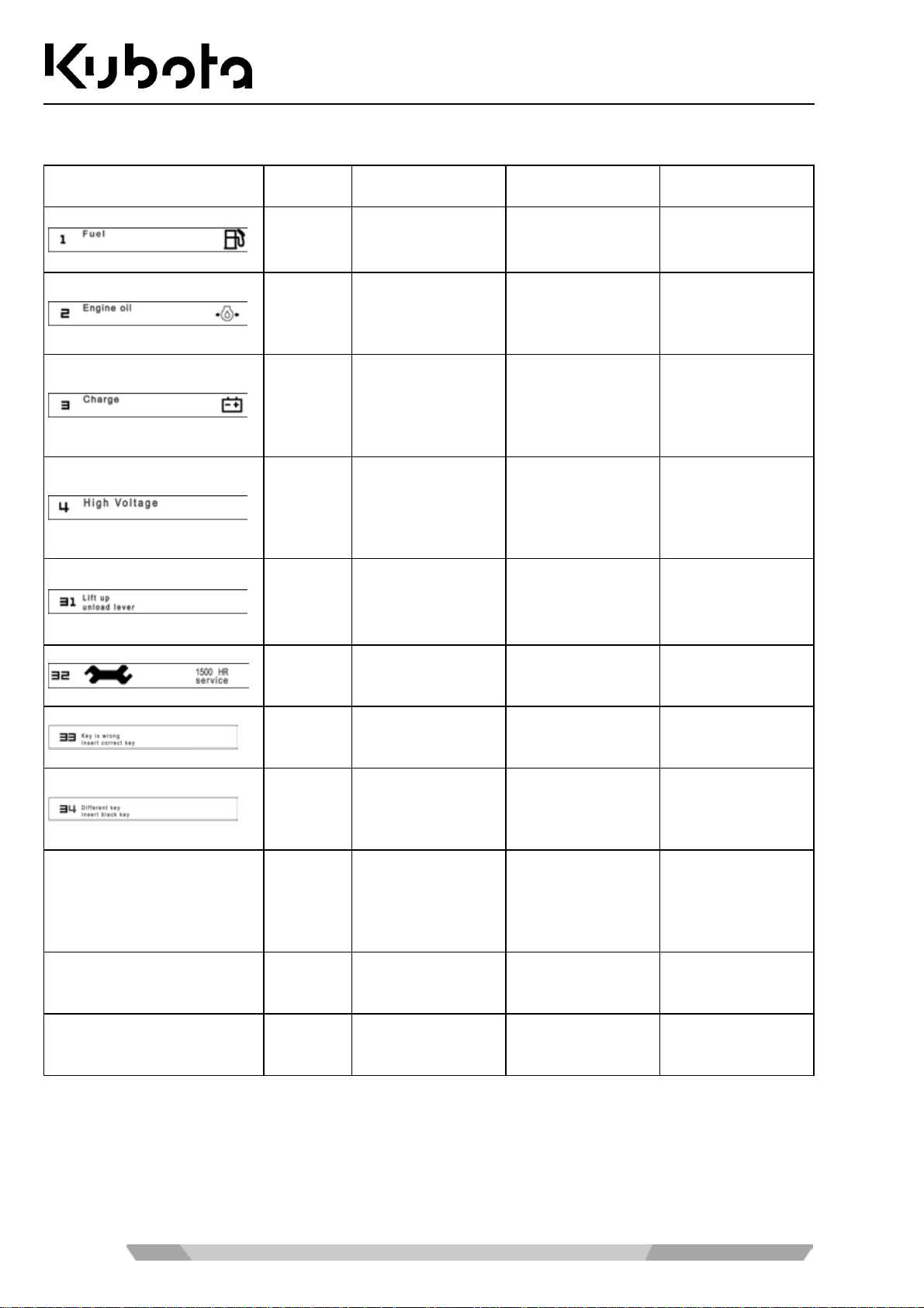
Troubleshooting: Display indications
Troubleshooting
Display Colour Problem/Error
- - - -
- - - -
No display
(warning light flashes)
Yellow • No fuel.
Red
Red
Red • Defective starter.
Yellow
Yellow
Yellow • Wrong key.
- -
Red
• Oil pressure too
• Faulty battery
• Charging error.
• Starting proce-
• Maintenance
• Try starting the
• The key is at-
• The key is part
• Short circuit in
low.
charger circuit.
dure with lowered control
console.
due.
engine with the
red key (for registration).
tached to a
metal object
(such as a key
ring).
of a bunch of
keys.
the sensor
power source.
Preliminary Meas-
ure
- -
Stop the engine
immediately.
Check the V-belt.
When the V-belt is
OK, let the engine
run until indicator
goes out.
Jump-start the
engine.
Engine does not
start up.
- -
- -
Engine does not
start.
Engine does not
start.
- -
Working lights light
up.
Solution
Refill.
Engine may be
defective. Immediately contact skilled
personnel.
If the indicator does
not go out, contact
skilled personnel.
If the indicator still
comes on after the
external ignition,
contact skilled
personnel.
Lift the control
console and repeat
the starting procedure.
Run the maintenance procedure.
Use correct key.
Try starting the
engine with the
black key.
Remove the metal
object and retry.
Detach the proper
key and retry.
Contact skilled
personnel.
90
Page 91

Maintenance
MAINTENANCE
The "Maintenance" section includes all care and maintenance tasks to be performed on the excavator.
A careful maintenance of the excavator will guarantee functional safety and longer service life.
Neglect of the servicing will void the warranty and any liability by KUBOTA.
Only use spare parts that ar e recommended by the manuf acturer. Non-appro ved spare parts of inf erior quality
or wrong classification res ult in an increased risk of accidents . Operators using non-appro ved spare parts are
fully responsible for any damage arising thereof.
Safety rules for maintenance
• Persons who work with or on the excavator must be provided b y the operator with, and where applica ble
use suitable personal protective equipment (PPE), for example suitable working clothes, safety shoes,
safety helmets, e ye protection, ear protection and a ir-filter m asks. The owner/ emplo yer bears the m ain responsibility for the PPE, which is specified by the safety rules for particular types of activity.
• Maintenance, cleaning and car e activities may onl y be carried out if the excavator is ful ly shut down. the
excavator must be sec ured against starting b y removal of the k ey. The bucket must alwa ys be lowered to
the ground for servicing.
• The bucket must always be lowered to the ground for servicing.
• When defects are detected durin g servic ing or m aintenance, the exc avator m ay onl y be operated af ter the
defects are remedied. Repairs may only be carried out by trained personnel.
• When carr ying out maintenance and care activit ies, always make sure that the ex cavator is secured and
stable.
• When working on the f uel system, smoking, open flam es and the operation of other ignition sourc es are
not allowed. The danger zo ne has to b e c lear l y marked with signs. A fire exting ui s her m us t be kept at hand
in the danger zone.
• All waste materials must be discarded in accordance with environmental protection regulations.
• Use the maintenance and care materials listed in the "Recommended lubricants" section (page 116).
• When working on the elec tric al s ystem , disc onnect it f rom the volt age s ource befor e startin g the work . T he
work may only be carried out by technicians with electrical training.
• Always use a ladder or a scaffold if the work cannot be reached by the operator.
• The controls may only be used while the operator is sitting on the operator's seat.
Personnel requirements
• The operator may only carry out cleaning and care activities.
• The servicing may only be performed by trained personnel.
91
Page 92

General maintenance chart: 50 to 500 hours of operation
Operator servicing
General maintenance
Check the engine oil level
Check the hydraulic oil level
Check the fuel level
Check the coolant level
Lubricate front-end attach-
ments
Check the V-belt
Check the water separator
Tracks and chassis: clean,
visually inspect and check
tension
Grease the swivel gear
Check nuts and bolts
Check, clean the air filter 1.)
Grease the pitch bearing
Check the battery electrolyte
level
Drain the water from the fuel
tank
1.) Under dusty conditions the air filter must be cleaned more frequently or replaced.
50 100 150 200 250 300 350 400 450 500 Interval Page
Elapsed hours of operation
Maintenance
daily 50
daily 51
daily 53
daily 50
daily 52
daily 51
daily 52
weekly (50 h) 110
50 h 109
100 h 114
200 h 101
200 h 110
500 h 107
500 h 103
92
Page 93
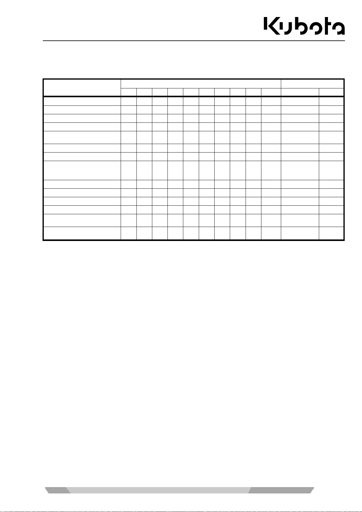
Maintenance
General maintenance chart: 550 to 1000 hours of operation
Operator servicing
General maintenance
Check the engine oil level
Check the hydraulic oil level
Check the fuel level
Check the coolant level
Lubricate front-end attachments
Check the V-belt
Check the water separator
Tracks and chassis: clean,
visually inspect and check
tension
Grease the swivel gear
Check nuts and bolts
Check, clean the air filter 1.)
Grease the pitch bearing
Check the battery electrolyte
level
Drain the water from the fuel
tank
1.) Under dusty conditions the air filter must be cleaned more frequently or replaced.
550 600 650 700 750 800 850 900 950 1000 Interval Page
Elapsed hours of operation
daily 50
daily 51
daily 53
daily 50
daily 52
daily 51
daily 52
weekly (50 h) 110
50 h 109
100 h 114
200 h 101
200 h 110
500 h 107
500 h 103
93
Page 94
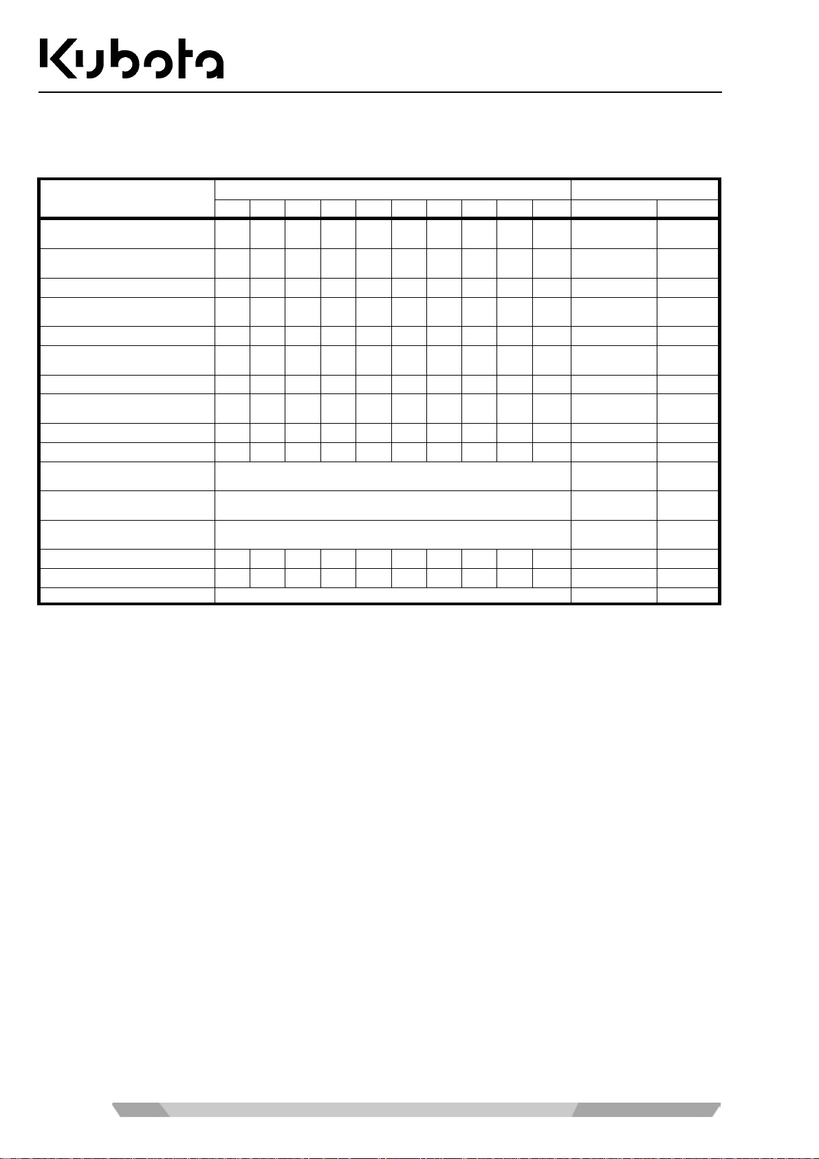
Maintenance
Servicing maintenance chart: 50 to 500 hours of operation
Servicing by skilled personnel or KUBOTA dealer
Servicing
Check coolant hoses and
clamps
Check/adjust the V-belt
tension
Grease the pilot valve linkage
Change the engine oil and oil
filter
Replace the fuel filter 4.)
Change the return filter for
the hydraulic oil tank 3.)
Replace the drive unit oil
Change the hydraulic oil and
suction filter 2.)
Replace the in-line filter
Replace air filter elements 1.)
Change the running gear and
track roller oil
Check the alternator and
starter motor
Check electric cables and
connections
Safety inspection
Change the coolant
Change hydraulic hoses Please contact your KUBOTA dealer. every 6 years --
50 100 150 200 250 300 350 400 450 500 Interval Page
z
* The servicing identified with ● must be carried after the specified hours of operation after initial operation have been
reached.
1.) Under dusty conditions the air filter must be cleaned more frequently or replaced.
2.) When using a breaker over 20% → every 800 h.
When using a breaker over 40% → every 400 h.
When using a breaker over 60% → every 300 h.
When using a breaker over 80% → every 200 h.
3.) When using a breaker up to 50% → every 200 h.
When using a breaker over 50% → every 100 h.
4.) Earlier if necessary.
Elapsed hours of operation *
z
Please contact your KUBOTA dealer. 2000 h -Please contact your KUBOTA dealer. 2000 h -Please contact your KUBOTA dealer. annually 112
250 h 98
250 h 97
250 h 112
500 h 98
500 h 102
500 h 103
500 h 112
1000 h 104
1000 h 113
1000 h 101
annually 118
every 2 years 100
94
Page 95
Maintenance
Servicing maintenance chart: 550 to 1000 hours of operation
Servicing by skilled personnel or KUBOTA dealer
Servicing
Check coolant hoses and
clamps
Check/adjust the V-belt
tension
Grease the pilot valve linkage
Change the engine oil and oil
filter
Replace the fuel filter 4.)
Change the return filter for
the hydraulic oil tank 3.)
Replace the drive unit oil
Change the hydraulic oil and
suction filter 2.)
Replace the in-line filter
Replace air filter elements 1.)
Change the running gear and
track roller oil
Check the alternator and
starter motor
Check electric cables and
connections
Safety inspection
Change the coolant
Change hydraulic hoses Please contact your KUBOTA dealer. every 6 years --
550 600 650 700 750 800 850 900 950 1000 Interval Page
1.) Under dusty conditions the air filter must be cleaned more frequently or replaced.
2.) When using a breaker over 20% → every 800 h.
When using a breaker over 40% → every 400 h.
When using a breaker over 60% → every 300 h.
When using a breaker over 80% → every 200 h.
3.) When using a breaker up to 50% → every 200 h.
When using a breaker over 50% → every 100 h.
4.) Earlier if necessary.
Elapsed hours of operation
Please contact your KUBOTA dealer. 2000 h -Please contact your KUBOTA dealer. 2000 h -Please contact your KUBOTA dealer. annually 112
250 h 98
250 h 97
250 h 112
500 h 98
500 h 102
500 h 103
500 h 112
1000 h 104
1000 h 113
1000 h 101
annually 118
every 2 years 100
95
Page 96
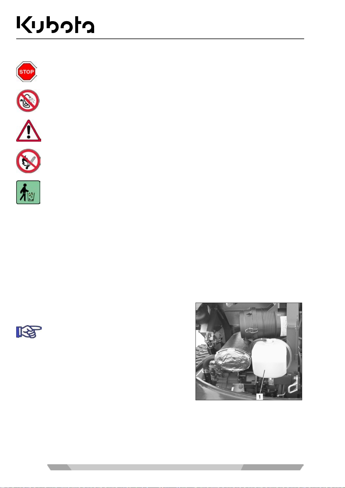
Maintenance
Cleaning the excavator
Before cleaning, shut down the engine and secure it against starting.
If a steam cleaner is use d for cleaning the excavator , do not direct t he steam jet at electric components.
Do not direct a water jet into the intake opening of the air filter.
Do not clean the excavator with inflammable liquids.
The excavator may only be washed at suitable places (using oil and grease separators).
The excavator can be cleaned wit h water and a commercial cle aning agent. M ake sure no water gets into the
electrical system.
Use a plastic cleaner for plastic parts.
Before cleaning, make sure to tape the air inlet for the air conditioner and heater system at the swivel frame.
Maintenance
Adhere to the instructions for regular servicing to keep the excavator in good condition.
Refilling the coolant
• Check the antifreeze conte nt with a n antif ree ze tes ter that is
qualified for -25 °C.
The antifreeze portion of the coolant should not
exceed 45%.
• Open the engine compartment cover (page 82).
• Open the coolant expansio n reservoir cap while the engine
is cold and fill pre-mixed coolant up to the FULL mark (1).
If the coolant expansion reservoir was completely empty, check the coolant level in the radiator.
For checking the fluid level of the radiator, remove the side panel (page 83).
96
Page 97
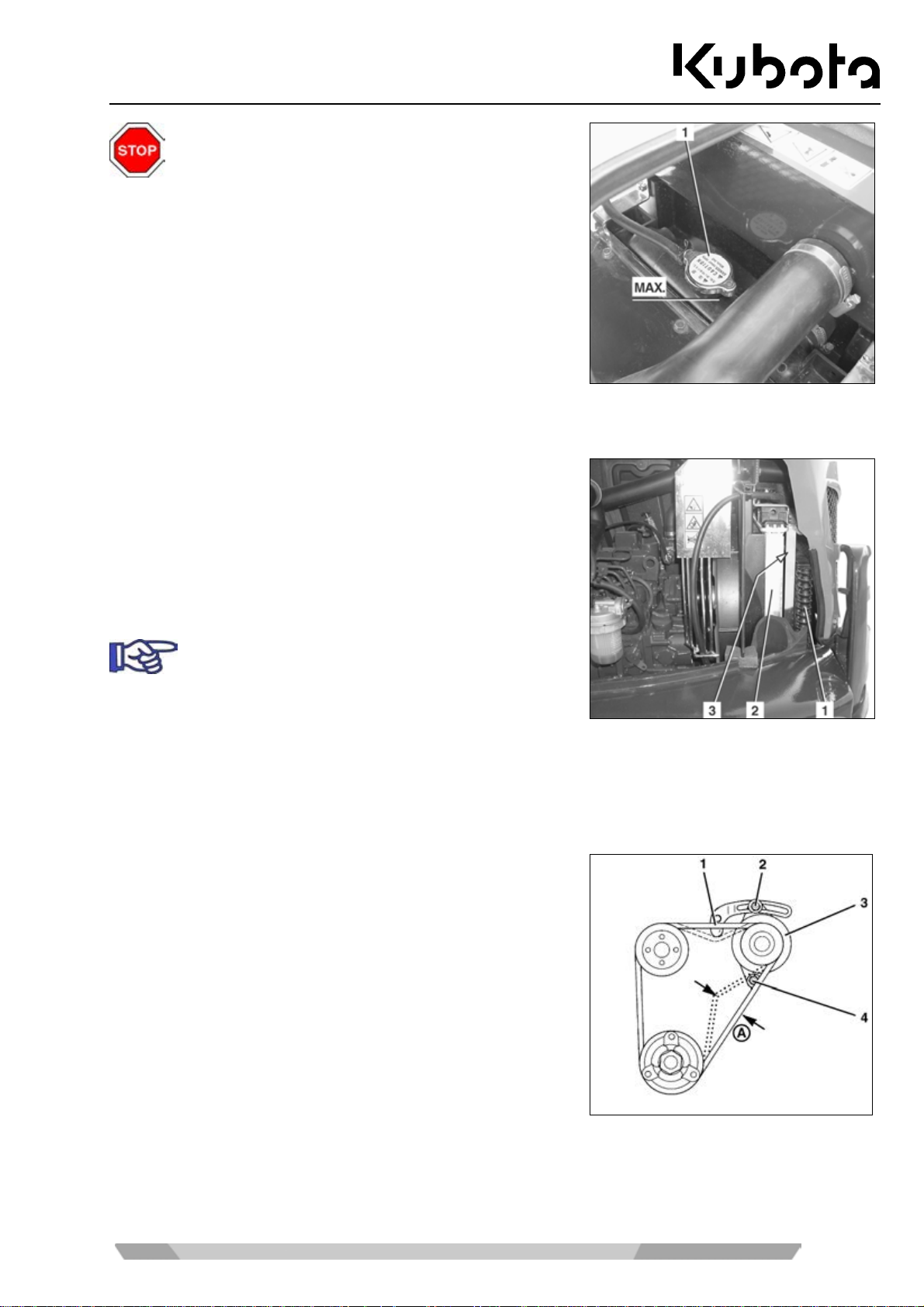
Maintenance
Do not open the radiator cap while the engine is still
hot, risk of scalding.
• Remove the radiator cap (1) by turning it anticlockwise.
• T he coolant level sh ould reach the M AX. mark ( see figure);
if not, add coolant.
• Refit the radiator cap and close the expansion reservoir.
• Close the engine compartment cover.
• If required, install the right side panel.
Cleaning the radiator
• Open the engine compartment cover (page 82).
• Clean the radiator (1 and 2) from the engine side with a
water jet or with compres sed air. Do not use high-press ure
cleaners.
• Pa y particular attention to the s pace (3) between the radia-
tor and oil cooler, as leaves tend to collect here.
If required, remove the side panel (page 83).
• Check the radiator for damage after cleaning it.
• Close the engine compartment cover.
Checking and adjusting the V-belt tension
• Open the engine compartment cover (page 82).
• Depress the V-belt (1) at point "A". The V-belt deflection
should be approx. 10 mm.
• Check the V-belt for proper condition and cracks.
• To tighten the V-belt, loos e n the mounting screws (2 a nd 4) ,
swing the alternator (3). Tighten the fastening screws and
check the tension of the V-belt.
• Close the engine compartment cover.
97
Page 98
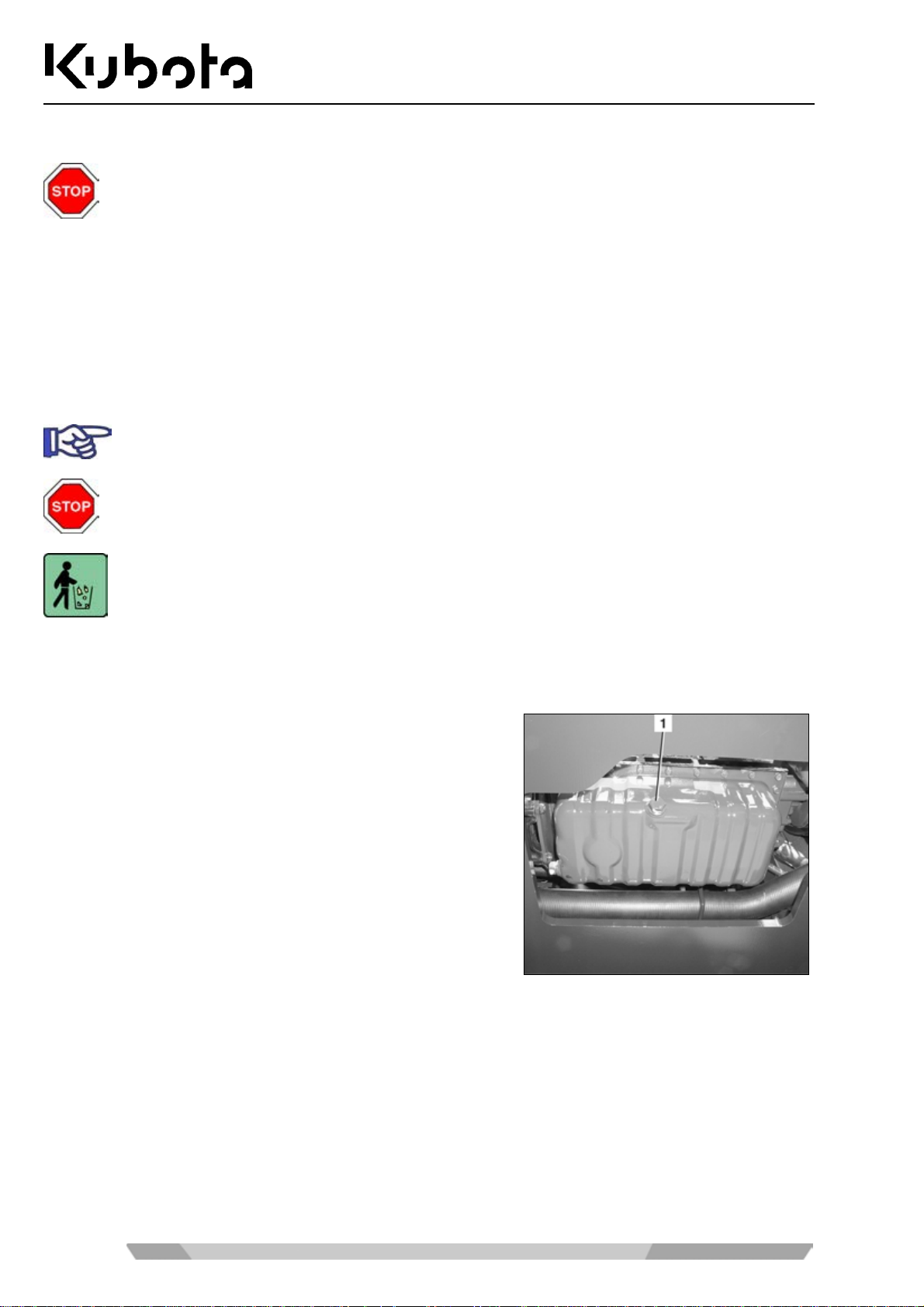
Maintenance
Checking the coolant hoses
Carry out the inspection while the engine is cold.
• Open the engine compartment cover (page 82).
Check all hose connection s on the engine and to the radiator or to the heater fan (c ab version) for condition
(cracks, bulges, hard s pots) and firm seating of the c lamps. If necessar y, have the hoses replaced by trained
personnel.
• Close the engine compartment cover.
Replacing the engine oil and oil filter
The engine oil change must be carried out while the engine is warm.
Caution: the engine oil and the oil filter are very hot → risk of scalding!
Place an oil pan w ith a capacity of about 12 L under the eng ine oil drain. The e ngine oil should
not be allowed to seep into the earth a nd it must b e dis carded like th e oil fil ter in a ccor dance with
the applicable environme nt protec ti on regul ati ons .
• Open the engine compartment cover (page 82).
Draining the engine oil
• Remove the oil drain plug (1) and let the engine oil drain
into the oil drain pan. Insta ll the oil drain plug using a new
seal.
98
Page 99
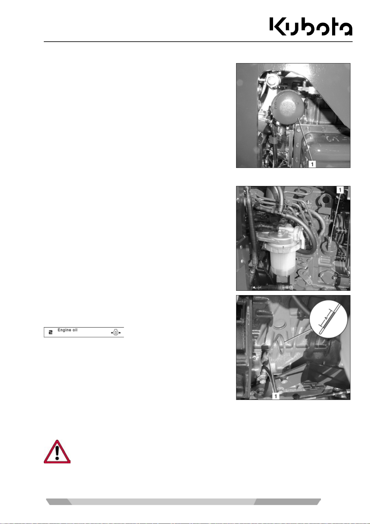
Maintenance
Replacing the oil filter
• Place an oil drain pan under the oil filter and r emove the o il
filter (1) with a filter wrench by turning it anticlockwise.
• Coat the sealing ring of the new oil filter with engine oil.
• Inst all and tighten the oil fil ter by hand. Do not use the filter
wrench.
Filling the engine oil
• Open the engine compartment cover (page 82).
• Unscrew the oil filler cap (1) and fill engine oil. See the
"Recommended lubricants" section (page 116).
Filling capacity: 5 L
• Install the oil filler cap.
• Start the engine. The follo wing message should disappear
immediately after the engi ne has star ted; if not, stop th e engine immediately and contact trained personnel.
• Let the engine run for approx. 2 minutes and then stop it.
Check the oil level after 5 minutes.
• Pull out the oil dipstick (1) and wipe it with a clean cloth.
• Insert the oil dipstick c ompletely and p ull it out agai n. T he oil level sho uld be in t he "A" ar ea. If the oil level
is too low, add engine oil. The amount of oil between the bottom and top of area "A" is 1.9 L.
When the oil level is too high or too low, the engine might get damaged during operation.
• When changing the engine oil, fill engine oil up to the MAX mark.
• Close the engine compartment cover.
99
Page 100
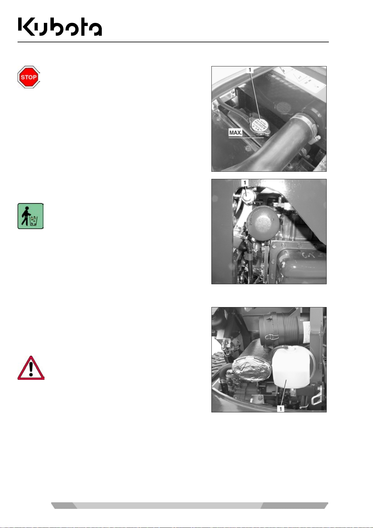
Replacing the coolant
Drain the coolant only when the engine is cold.
Total cooling system capacity: 5.6 L
• Open the engine compartment cover (page 82).
• Remove the right side panel (page 83).
• Open the radiator cap (1).
• Open the centr al coolant drain plug ( 1) and drain the cool-
ant completely.
Fill the coolant in a container and dispose of it in
accordance with the prevailing environmental protection regulations.
Purge the cooling s ystem if the cool ant is very dirt y. To do this,
spray water without additives into the cooling system with a
hose through the filler opening until clear water em erges at the
outlet.
Maintenance
• Close the central drain plug.
• Remove the coolant expansion reservoir (1) and drain it,
cleaning it if necessary. Refit the reservoir.
• Fill the premixed coolant into the radiator and expansion
reservoir.
Do not operate the cooling system with pure water
(even in summer). The antifreeze also contains a
corrosion inhibitor.
• Let the engine idle for about 5 min, shut it off and check the coolant level in the radiator. The coolant
should reach the MAX. mark; if not, add coolant.
• Close the engine compartment cover.
• Install the right-hand side panel.
100
 Loading...