

Page 1

WORKSHOP MANUAL
KiSC issued 08, 2015 A
KUBOTA EXCAVATOR
KX080-4
Page 2

CONTENTS
KiSC issued 08, 2015 A
TO THE READER
TO THE READER
I INFORMATION
CONTENTS
INFORMATION
1. SAFETY FIRST ............................................ I-1
2. IN THE INTEREST OF WORK
SAFETY........................................................ I-2
3. LABELS DISPLAYED TO PROMOTE
WORK SAFETY............................................ I-6
4. MAIN SPECIFICATIONS ............................ I-12
5. DIMENSIONS ............................................. I-13
G GENERAL
CONTENTS
GENERAL
1. CHECKING EXCAVATOR
IDENTIFICATION ........................................G-1
2. ENGINE IDENTIFICATION .........................G-2
3. MUFFLER FULL ASSEMBLY
IDENTIFICATION ........................................G-5
4. GENERAL PRECAUTIONS.........................G-7
5. HANDLING PRECAUTIONS FOR
ELECTRICAL PARTS AND WIRING.........G-11
6. TIGHTENING TORQUES ..........................G-16
7. OIL AND WATER CAPACITY TABLE .......G-20
8. MAINTENANCE INTERVALS....................G-21
1 MACHINE BODY
CONTENTS
SERVICING
1. FRONT ...................................................... 1-S1
2. SWIVEL FRAME........................................ 1-S8
3. TRACK FRAME ....................................... 1-S22
4. MEASURING MACHINE
PERFORMANCE ..................................... 1-S38
5. SWIVEL GEAR BACKLASH
PERFORMANCE ..................................... 1-S40
2 ENGINE
CONTENTS
GENERAL
1. SPECIFICATIONS.....................................2-G1
2. DIMENSIONS ............................................2-G2
3. PERFORMANCE CURVES .......................2-G3
4. FAN DRIVE................................................2-G4
3 HYDRAULIC SYSTEM
CONTENTS
MECHANISM
1. DIAGRAM OF HYDRAULIC CIRCUIT...... 3-M1
2. HYDRAULIC DEVICE LAYOUT ............... 3-M3
3. PUMP ....................................................... 3-M4
4. CONTROL VALVE.................................. 3-M12
5. SWIVEL MOTOR.................................... 3-M29
6. TRAVEL MOTOR ................................... 3-M34
7. HYDRAULIC CYLINDER ........................ 3-M39
8. PILOT VALVE......................................... 3-M42
9. SHOCKLESS VALVES........................... 3-M52
10. SOLENOID VALVE................................. 3-M54
SERVICING
1. PUMP......................................................... 3-S1
2. CONTROL VALVE................................... 3-S17
3. SWIVEL MOTOR ..................................... 3-S26
4. SWIVEL JOINT ........................................ 3-S41
5. TRAVEL MOTOR..................................... 3-S49
6. CYLINDER............................................... 3-S69
7. PILOT VALVE .......................................... 3-S71
8. SHOCKLESS VALVES .......................... 3-S106
9. SWIVEL SHUTTLE VALVE ................... 3-S107
10. SOLENOID VALVE ................................ 3-S108
11. ROUTING OF HYDRAULIC HOSES .....3-S112
12. MEASURING HYDRAULIC DEVICE
PERFORMANCE ................................... 3-S133
13. HYDRAULIC DEVICE
PERFORMANCE STANDARDS............ 3-S158
14. TROUBLESHOOTING ........................... 3-S165
4 ELECTRICAL SYSTEM
CONTENTS
SERVICING
1. LAYOUT OF ELECTRICAL DEVICES
AND WIRING ROUTING ........................... 4-S1
2. METER PANEL OPERATION ................. 4-S10
3. INSPECTIONS......................................... 4-S44
4. TROUBLESHOOTING (START-UP
EQUIPMENT VERSION) .........................4-S50
5. METHODS FOR DIAGNOSING
ERRORS.................................................. 4-S51
6. TROUBLESHOOTING (METER
PANEL VERSION)................................... 4-S53
5 CABIN
CONTENTS
MECHANISM
1. AIR CONDITIONING SYSTEM................. 5-M1
2. WIPER .................................................... 5-M17
SERVICING
1. TROUBLESHOOTING............................... 5-S1
2. SERVICE SPECIFICATIONS .................... 5-S4
3. TORQUE.................................................... 5-S5
4. PRECAUTIONS WHEN REPAIRING
THE REFRIGERANT SYSTEM ................. 5-S6
5. INSPECTING AND CHARGING THE
REFRIGERANT SYSTEM ....................... 5-S11
6. INSPECTION AND DISASSEMBLY ........5-S20
7. WINDOW WASHER ................................ 5-S36
8. CABIN GLASS REMOVAL AND
MOUNTING ............................................. 5-S38
9. REMOVAL AND INSTALLATION OF
GLASS ..................................................... 5-S52
10. FRONT WINDOW .................................... 5-S57
Page 3

TO THE READER
NOTE
IMPORTANT
KiSC issued 08, 2015 A
This Workshop Manual provides service personnel with information about the mechanisms, service
and maintenance of the construction machinery. This Workshop Manual is divided into 3 sections,
General, Mechanisms and Service.
General
This section contains information such as engine and equipment ID numbers, general precautions,
maintenance schedules, inspections and maintenance items and special tools.
Mechanisms
This section describes the structure of mechanisms and explains their functions.Be sure that you
fully understand this Mechanisms section prior to performing any service work, such as troubleshooting
or when performing any disassembly or assembly work.
Service
This section contains information and procedures for performing maintenance on the backhoe, such
as troubleshooting, service specification tables, torque specifications, items to be inspected and
adjusted, disassembly and assembly procedures, as well as precautions, maintenance standard values
and usage limits.
All of the illustrations, specifications and other information in this manual were created based on the
latest model at the time of publication.
Please be aware that changes to the content may be made without prior notice.
• Corresponding model list
Machine Model Engine Model
KX080-4 V3307-CRS-T4
• Refer to the information of the engine below.
• Engine model : V2607-CR-E4B, V2607-CR-TE4B, V3307-CR-TE4B
• Web PDF-Code : No.9Y111-06740
• Hard Copy-Code : No.9Y121-06740
• CD-ROM-Code : No.9Y131-06740
© KUBOTA Corporation 2013
January, 2013
Page 4

Record of Revisions
KiSC issued 08, 2015 A
Last digit of
the Code
No.
Date Main Revised Point and Corrective Measures Remarks
1 2015.08.05
2
3
4
• Add the contents of pump assembly and disassembly,
the contents of cabin glass removal and mounting.
S. M
Page 5

I INFORMATION
KiSC issued 08, 2015 A
Page 6

INFORMATION
KiSC issued 08, 2015 A
CONTENTS
1. SAFETY FIRST .............................................................................................................................. I-1
2. IN THE INTEREST OF WORK SAFETY ........................................................................................ I-2
[1] WORKING SAFELY WITH THE EQUIPMENT MEANS ALWAYS FOLLOWING
THESE INSTRUCTIONS:......................................................................................................... I-2
(1) Precautions Before Working on the Machine ..................................................................... I-2
(2) Precautions Before Working on the Equipment.................................................................. I-3
3. LABELS DISPLAYED TO PROMOTE WORK SAFETY................................................................. I-6
[1] LOCATIONS ............................................................................................................................. I-6
[2] LABEL MAINTENANCE ......................................................................................................... I-11
4. MAIN SPECIFICATIONS.............................................................................................................. I-12
5. DIMENSIONS ............................................................................................................................... I-13
Page 7
KX080-4, WSM
SAFETY FIRST
DANGER
WARNING
CAUTION
IMPORTANT
NOTE
KiSC issued 08, 2015 A
INFORMATION
1. SAFETY FIRST
• This "Safety Alert Symbol" is used in this manual and on labels on equipment to indicate important
issues and warn of the danger of personal injury. Read and follow these warnings carefully.
• It is important that you thoroughly read these instructions and safety rules prior to working on the
equipment and that you always follow them.
• Indicates that failure to follow the warning will result in serious injury or death.
• Indicates that failure to follow the warning may result in serious injury or death.
• Indicates that failure to follow the warning may result in injury.
• Indicates that failure to follow the warning may result in damage to or a breakdown of the equipment.
• Indicates supplementary explanations that will be helpful when using the equipment.
[NOTE]
• Indicates other supplementary information to take note of.
RY9212001INI0001US0
I-1
Page 8
KX080-4, WSM
KiSC issued 08, 2015 A
INFORMATION
2. IN THE INTEREST OF WORK SAFETY
[1] WORKING SAFELY WITH THE EQUIPMENT MEANS ALWAYS
FOLLOWING THESE INSTRUCTIONS:
(1) Precautions Before Working on the Machine
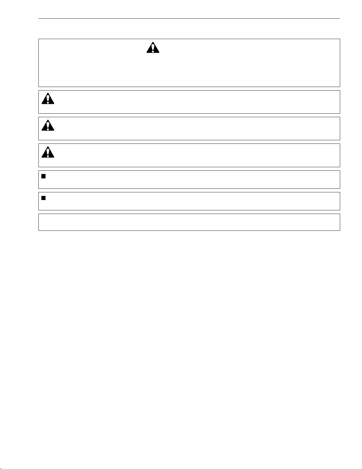
Before starting any service or maintenance work
• Read all the general and safety instructions in this
manual, as well as the decals on your equipment.
• Always stop the engine whenever you leave the
driver's seat to inspect or clean the machine or its
devices, or to inspect or adjust parts.
• Choose a safe spot for inspecting the equipment-on
flat, hard ground.
RY9212001INI0002US0
• When performing maintenance on the equipment,
hang the DO NOT OPERATE sign where it will be
obvious from and around the driver's seat.
• When performing maintenance or repairs, always
lower attachments to the ground, stop the engine
and set the brake.
• When performing maintenance on the equipment,
always disconnect the negative battery cable.
• Before using tools, make sure you understand how
to use them correctly and use tools in good condition
and of the right size for the job.
RY9212001INI0003US0
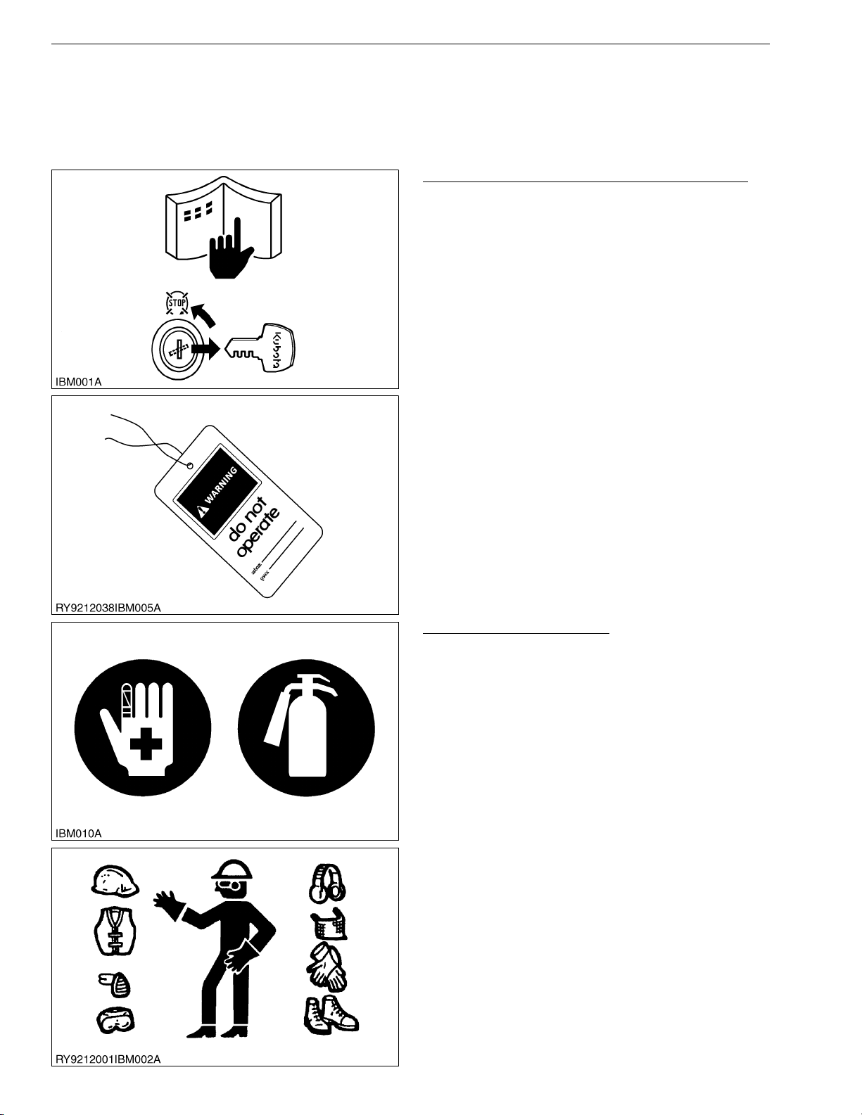
Be Ready for an Emergency
• Keep a first-aid kit and fire extinguisher close at hand
so you can use it when needed.
• Keep emergency contact information for doctors,
hospitals and ERs handy.
RY9212001INI0004US0
• Wear clothes appropriate for working on equipment.
Do not wear loose-fitting clothes as they may catch
on the machine controls.
• When working on the equipment, use all safety gear,
such as a helmet, safety glasses and shoes, that are
required by law or regulation.
• Never perform maintenance while drowsy or under
the influence of alcohol or drugs.
RY9212001INI0005US0
I-2
Page 9
KX080-4, WSM
CAUTION
KiSC issued 08, 2015 A
(2) Precautions Before Working on the Equipment
• Stop the machine on a hard and level location and
make sure the area around the machine is free of
obstacles and hazardous materials. When parking
the machine indoors, select a spot that can be
properly ventilated.
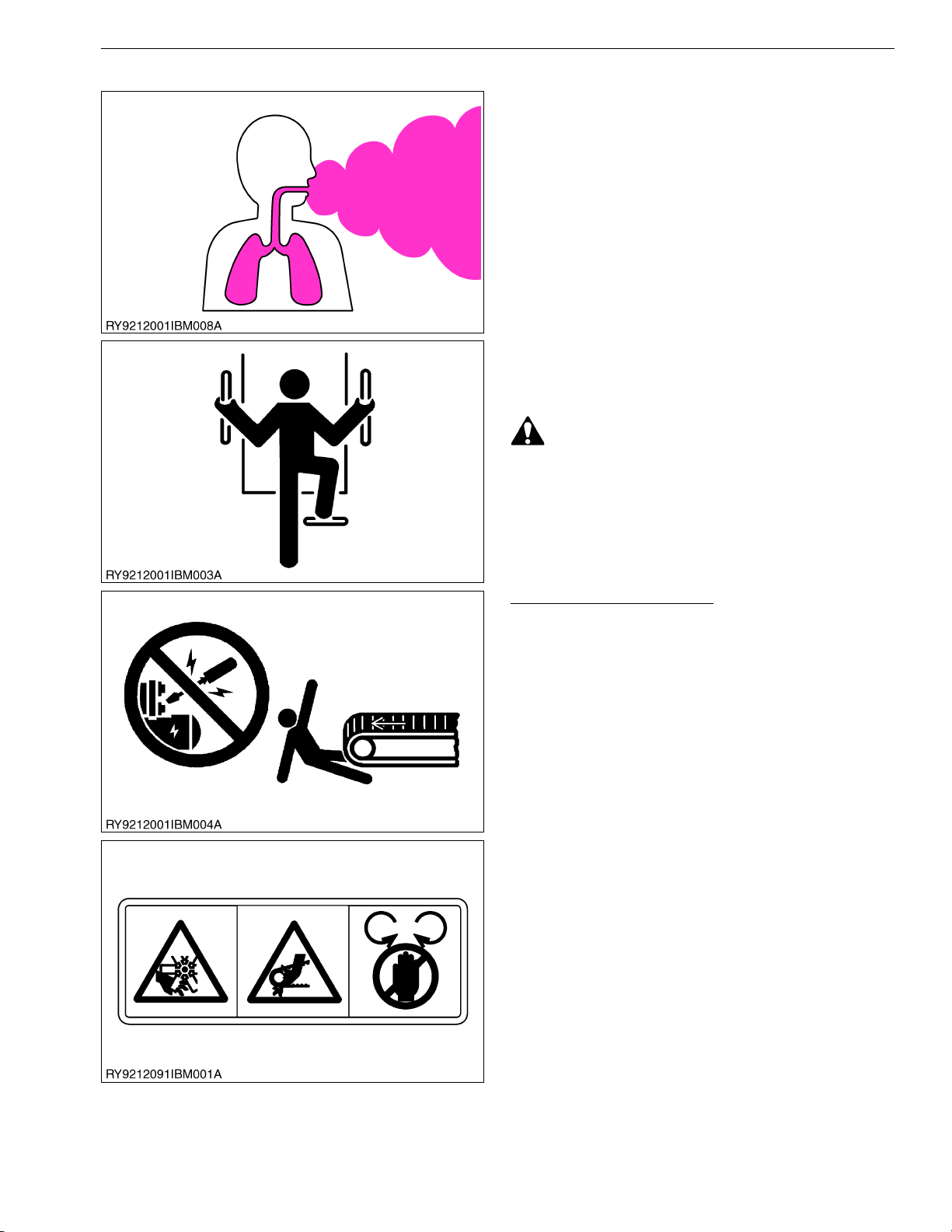
• When performing work such as with a hammer,
fragments may go flying, so make sure only
authorized persons are around the machine.
• Before servicing the machine, clean it off so there is
no mud, debris, oil or the like sticking to it.
• Before getting on/off of the machine, clean off
around the steps so there is no mud on them.
Always give yourself 3-point support when getting
on/off the machine.
• 3-point support means using both legs and one
hand or both hands and one leg as you climb
up/down.
INFORMATION
RY9212001INI0006US0
RY9212001INI0007US0
Starting the Machine Safely
• Before starting the engine, always sit in the driver's
seat and make sure the area is safe and clear.
• As it is dangerous, never start the engine from
anywhere but the driver's seat.
• Always check and make sure control lever(s) are not
engaged before starting the engine.
• Never start the engine by hot-wiring the starter
circuit. This is not only dangerous, but may damage
the machine.
RY9212001INI0008US0
• Whenever it is necessary to open the engine covers
or hood in order to service the machine, always prop
them open.
• If it is absolutely necessary to run the engine while
working on the machine, make sure you are clear of
all rotating or moving parts. Also take care not to
leave anything, such as tools or rags, near any
moving parts.
RY9212001INI0009US0
I-3
Page 10
KX080-4, WSM
KiSC issued 08, 2015 A
INFORMATION
• The engine, muffler, radiator, hydraulic line, etc.,
have parts that remain very hot even after the engine
has been stopped. Be sure to avoid these parts, as
touching them can result in burns. Radiator coolant,
hydraulic fluid and oil also remain hot. Therefore, do
not attempt to remove caps and plugs, etc., before
these fluids have sufficiently cooled.
• Make sure the coolant temperature has dropped
sufficiently before opening the radiator cap.
Also, since the inside of the radiator is pressurized,
when removing the cap, first loosen it to release the
pressure before removing the cap completely.
RY9212001INI0016US0
• The pressure in the hydraulic circuit stays at
pressure even after the engine stops.
Before removing parts, such as hydraulic devices
from the machine, first release the pressure. Please
note that when releasing residual pressure, the
machine itself and/or implements may move without
warning, so be very careful when releasing the
pressure.
• Oil gushing out under pressure is extremely
dangerous as it may pierce your skin or your eyes.
Similarly, oil leaking out of pinholes is not visible.
So when checking for oil leaks, always wear safety
glasses and gloves and use a piece of cardboard or
a wood block to shield yourself from oil.
RY9212001INI0011US0
No Smoking or Open Flames while Fueling
• Fuel is extremely flammable and dangerous.
Never smoke near fuel. If fuel is spilled on the
machine, its engine, or electrical parts, it may cause
a fire. If fuel is spilled, wipe it all up immediately.
• Never smoke while filling the machine with fuel.
And always tighten the fuel cap securely and wipe up
any spilled fuel.
RY9212001INI0012US0
• Always wear safety glasses and gloves when
handling the battery.
• The gas generated by the battery is flammable.
Never weld or use tools like a grinder near the
battery. And never smoke near it.
• When disconnecting the battery, always disconnect
the negative cable first. When connecting the
battery, always connect the positive cable first.
RY9212001INI0013US0
I-4
Page 11
KX080-4, WSM
KiSC issued 08, 2015 A
INFORMATION
• Grease is under high pressure inside the hydraulic
cylinder. It is very dangerous to loosen a grease
nipple quickly as it may shoot off. Always loosen
grease nipples slowly.
• And never face a grease nipple while loosening it.
RY9212001INI0014US0
Dispose of Waste Fluids Properly
• Never dispose of waste fluids on the ground, in the
gutter, a river, pond or lake. Always dispose of
hazardous substances like waste oil, coolant and
electrolytic fluid in accordance with the relevant
environmental protection regulations.
• Keep the safety plates clean so they can be read.
If a safety plate is damaged and comes off or
becomes illegible, put a plate with the same
warnings back in its place.
RY9212001INI0015US0
I-5
Page 12
KX080-4, WSM
KiSC issued 08, 2015 A
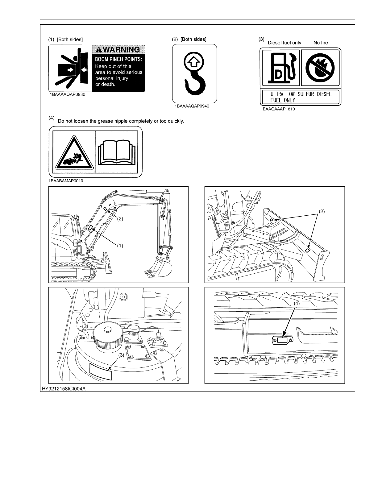
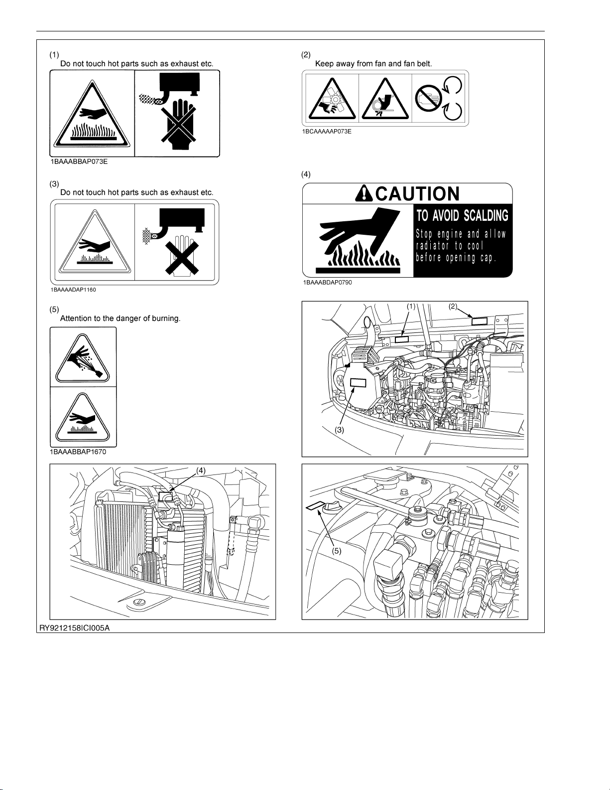
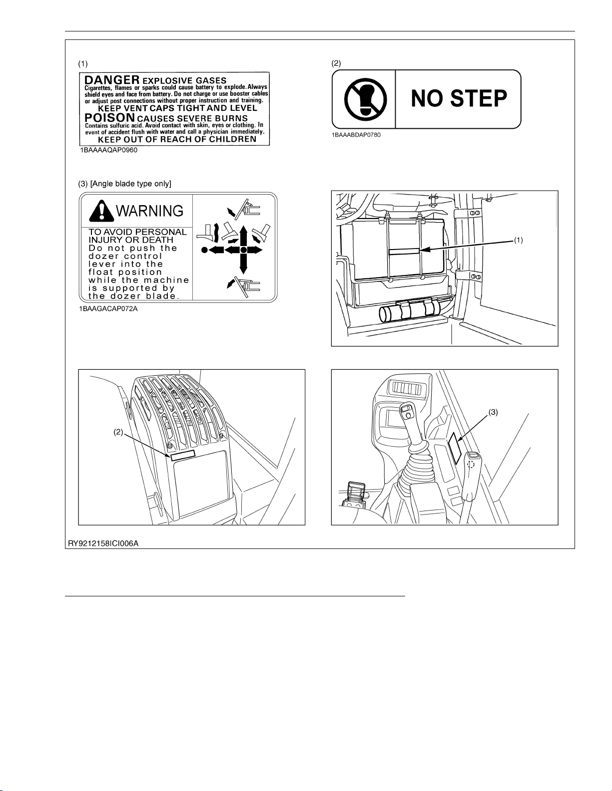
3. LABELS DISPLAYED TO PROMOTE WORK SAFETY
[1] LOCATIONS
INFORMATION
RY9212158INI0003US0
I-6
Page 13
KX080-4, WSM
KiSC issued 08, 2015 A
INFORMATION
RY9212158INI0004US0
I-7
Page 14
KX080-4, WSM
KiSC issued 08, 2015 A
INFORMATION
RY9212158INI0005US0
I-8
Page 15
KX080-4, WSM
KiSC issued 08, 2015 A
INFORMATION
RY9212158INI0006US0
I-9
Page 16
KX080-4, WSM
KiSC issued 08, 2015 A
INFORMATION
RY9212158INI0007US0
I-10
Page 17
KX080-4, WSM
KiSC issued 08, 2015 A
INFORMATION
[2] LABEL MAINTENANCE
Thoroughly Read, Understand and Follow Safety Precautions on Labels
• Always keep labels in a clean, undamaged state.
• If labels get dirty, wipe them off with soapy water and a soft cloth.
• When using a pressure washer to clean the equipment, do not spray any labels directly as doing so may make
• If a label is damaged or lost, order a new one from your dealer and affix it as before.
• Before affixing a new label, completely wipe off any dirt or grime on the surface, allow it to dry and then affix in
• When replacing a part that has a label on it, replace the label at the same time.
RY9212158INI0008US0
If solvents such as paint thinner or engine oil are used, the text and or figures may fade away.
them peel off.
the same place.
RY9212001INI0018US0
I-11
Page 18
KX080-4, WSM
NOTE
KiSC issued 08, 2015 A
INFORMATION
4. MAIN SPECIFICATIONS
KUBOTA EXCAVATOR
Model name KX080-4
Type Cabin Angle Blade type Cabin
Rubber
Operating weight
(including operator's weight)
tracks
8290 kg
18280 lbs
Type Water cooled 4 cycle diesel engine with 4 cylinder
Model name KUBOTA V3307-CRS-T4
Total displacement 3331 cc (203.3 cu.in.)
Engine
Engine
power
SAE gross 52.2 kW (70.0 Hp)
SAE net 48.8 kW (65.5 Hp)
Rated speed 2000 rpm
Low idling speed 1000 rpm
Unit swing speed 9.5 rpm
Travel
speed
Fast 4.9 km / h (3.1 mph)
Slow 2.7 km / h (1.7 mph)
36.0 kPa
Performance
Ground pressure
(With operator)
(0.367
kgf/cm
5.22 psi
Climbing angle *36 % (20 deg)
Angle in case of crossing
slope
Width x Height
Blade
Max
swing
Left – 0.44 rad (25 deg)
Right – 0.44 rad (25 deg)
Left 1.22 rad (70 deg)
Boom swing angle
Right 1.05 rad (60 deg)
Max. displacement
Pressure
(Theoretical)
connection for
attachments
Max. pressure
Fuel tank capacity 115 L (30.4 U.S.gal)
Steel tracks
(450 width)
8340 kg
18390 lbs
36.2 kPa
(0.369
2
)
kgf/cm
5.25 psi
2200 x 500 mm
86.6 x 19.7 in.
Steel tracks
Rubber
(600 width)
8470 kg
18670 lbs
27.6 kPa
(0.281
2
)
kgf/cm
2)
4.00 psi
8680 kg
19140 lbs
37.5 kPa
(0.382
kgf/cm
5.44 psi
*27 % (15 deg)
100 L (26.4 U.S.gal) / min
20.6 MPa
210 kgf/cm
2
2987 psi
tracks
2
)
2200 x 510 mm
86.6 x 20.1 in.
Steel tracks
(450 width)
8730 kg
19250 lbs
37.7 kPa
(0.384
kgf/cm
5.47 psi
2
)
• Above dimensions are based on the machine with KUBOTA original bucket and 2100 arm.
• Specifications subject to change without notice.
• With unloaded digging bucket.
• Firm compacted soil.
• Operators must exercise extra caution and follow instructions in the operator's manual.
• Worse condition or heavier attachment to the above will decrease climbing angle.
RY9212158INI0001US0
I-12
Page 19
KX080-4, WSM
KiSC issued 08, 2015 A
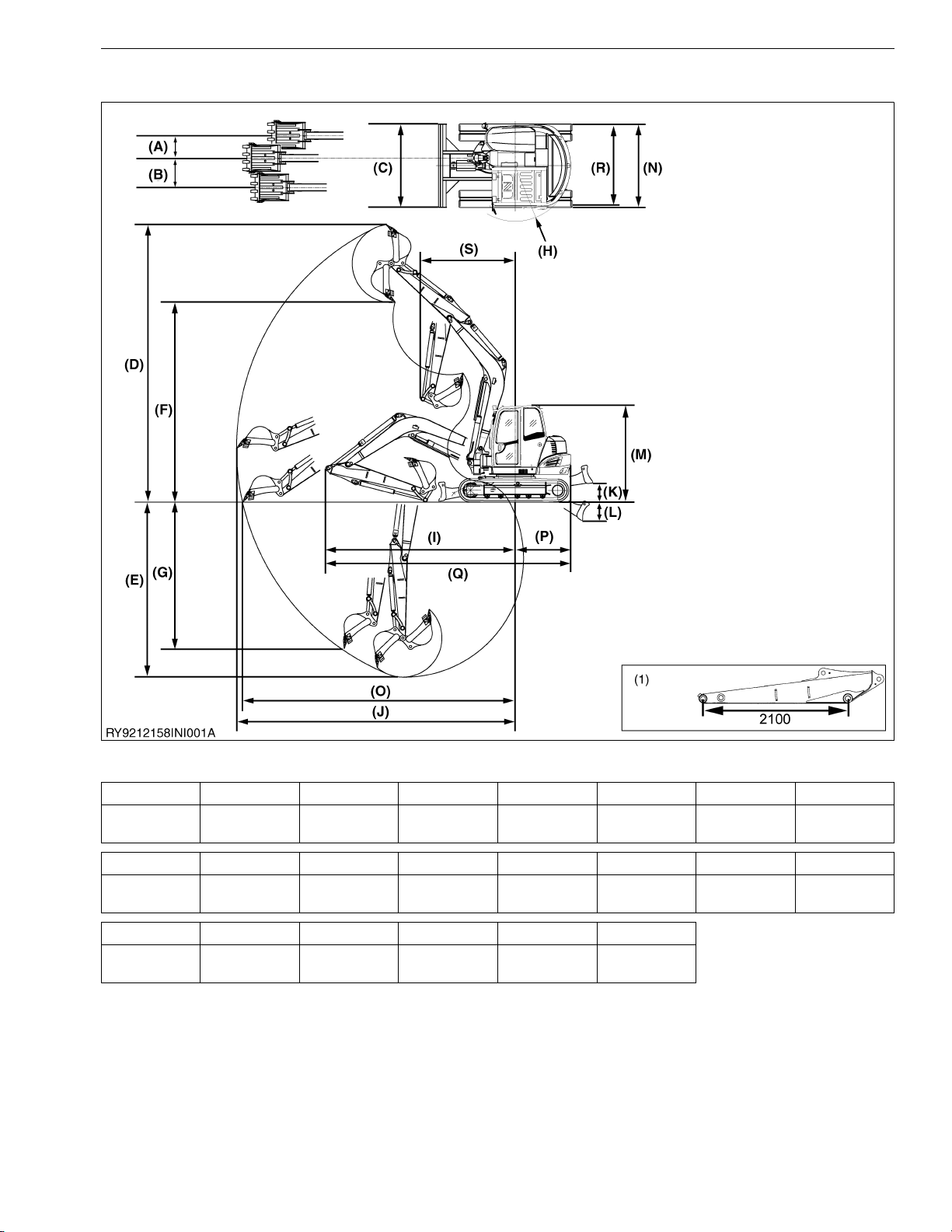
5. DIMENSIONS
INFORMATION
(1) Arm length (2100 Arm)
• Above dimensions are based on the machine with KUBOTA original bucket.
• Above dimensions are based on the machine with rubber track.
• Specifications subject to change without notice.
KX080-4
KX080-4
KX080-4
(A) (B) (C) (D) (E) (F) (G)
590 mm
23.2 in.
(H) (I) (J) (K) (L) (M) (N)
1460 mm
57.5 in.
(O) (P) (Q) (R) (S)
7170 mm
282.3 in.
770 mm
30.3 in.
4990 mm
196.5 in.
1460 mm
57.5 in.
2200 mm
86.6 in.
7330 mm
288.6 in.
6450 mm
253.9 in.
7300 mm
287.4 in.
500 mm
19.7 in.
2150 mm
84.6 in.
5250 mm
206.7 in.
500 mm
19.7 in.
2490 mm
98.0 in.
4600 mm
181.1 in.
2540 mm
100.0 in.
RY9212158INI0002US0
I-13
3850 mm
151.6 in.
2200 mm
86.6 in.
Page 20

G GENERAL
KiSC issued 08, 2015 A
Page 21

GENERAL
KiSC issued 08, 2015 A
CONTENTS
1. CHECKING EXCAVATOR IDENTIFICATION .............................................................................. G-1
2. ENGINE IDENTIFICATION .......................................................................................................... G-2
[1] MODEL NAME AND SERIAL NUMBER ................................................................................ G-2
[2] E4B ENGINE .......................................................................................................................... G-3
[3] CYLINDER NUMBER ............................................................................................................. G-4
3. MUFFLER FULL ASSEMBLY IDENTIFICATION ......................................................................... G-5
[1] PART NUMBER AND SERIAL NUMBER .............................................................................. G-5
4. GENERAL PRECAUTIONS.......................................................................................................... G-7
5. HANDLING PRECAUTIONS FOR ELECTRICAL PARTS AND WIRING .................................. G-11
[1] WIRING ................................................................................................................................ G-11
[2] FUSES.................................................................................................................................. G-13
[3] CONNECTOR ...................................................................................................................... G-13
[4] WASHING THE MACHINE WITH A HIGH-PRESSURE WASHER ..................................... G-15
6. TIGHTENING TORQUES........................................................................................................... G-16
[1] TORQUES FOR GENERAL USE NUTS AND BOLTS ........................................................ G-16
[2] TORQUE FOR HYDRAULIC HOSE FITTINGS ................................................................... G-17
(1) Torque for Hydraulic Hose Fittings ................................................................................. G-17
(2) Torques of Lock-Nuts for Elbows with Male Seats and Adaptors with O-rings
(Straight Threads)........................................................................................................... G-17
[3] HOSE CLAMP SCREW TORQUE ....................................................................................... G-18
7. OIL AND WATER CAPACITY TABLE ........................................................................................ G-20
8. MAINTENANCE INTERVALS..................................................................................................... G-21
Page 22
KX080-4, WSM
KiSC issued 08, 2015 A
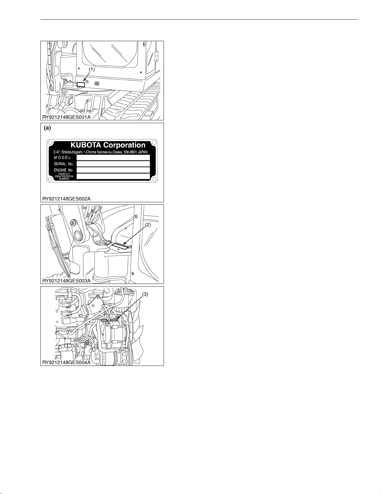
1. CHECKING EXCAVATOR IDENTIFICATION
When consulting with your local KUBOTA dealer about this
mini-excavator, please provide the model of the mini-excavator, its
frame and engine numbers and the number of hours on the hour
meter.
(1) Mini-excavator Nameplate
(Model, frame number, engine
number)
(2) Frame Number
(3) Engine Number
(a) Model Nameplate
RY9212148GEG0001US0
GENERAL
G-1
Page 23
KX080-4, WSM
KiSC issued 08, 2015 A
2. ENGINE IDENTIFICATION
[1] MODEL NAME AND SERIAL NUMBER
Be sure to check the engine nameplate and serial number when
you wish to consult about the engine.
The model and serial number of the engine need to be checked
prior to servicing the engine or replacing any of its parts.
Engine Serial No.
The engine serial number is the numerical ID of the engine and
is printed after the engine's model number.
The year and month of manufacture are indicated as follows.
Engine Series
Number or
Alphabet
1 05 (include: WG) 6
2V3703
308807
4 SM (include: WG) A EA, RK
5
Air Cooled
Series
Gasoline
Number or
Alphabet
B
GENERAL
Series
GZ, OC, AC, EA,
E
03 (KET
Production)
Production Year
Alphabet or
Number
1 2001 F 2015
2 2002 G 2016
3 2003 H 2017
4 2004 J 2018
5 2005 K 2019
6 2006 L 2020
7 2007 M 2021
8 2008 N 2022
9 2009 P 2023
A 2010 R 2024
B 2011 S 2025
C 2012 T 2026
D 2013 V 2027
E2014
(1) Engine Model Name and Serial
Number
Year
Alphabet or
Number
Year
(To be continued)
G-2
Page 24
KX080-4, WSM
NOTE
KiSC issued 08, 2015 A
(Continued)
Production Month and Lot Number
Month Engine Lot Number
January A0001 to A9999 from B0001
February C0001 to C9999 from D0001
March E0001 to E9999 from F0001
April G0001 to G9999 from H0001
May J0001 to J9999 from K0001
June L0001 to L9999 from M0001
July N0001 to N9999 from P0001
August Q0001 to Q9999 from R0001
September S0001 to S9999 from T0001
October U0001 to U9999 from V0001
November W0001 to W9999 from X0001
December Y0001 to Y9999 from Z0001
* Alphabetical letters "I" and "O" are not used.
(a)
e.g. V2607
(a) V2607: Engine Model Name
(b) 8: Engine Series (07 series)
(c) C: Production Year (2012)
(d) L: Production Month (June)
(e) A001: Lot Number: (0001 to 9999 or A001 to Z999)
(b)C(c)L(d)
- 8
(e)
A001
RY9212148GEG0002US0
GENERAL
[2] E4B ENGINE
[Example: Engine Model Name V2607-CR-TE4(C)B-XXXX or V2607-CR-TIE4(C)B-XXXX]
The emission controls previously implemented in various countries to prevent air pollution will be stepped up as
Nonroad Emission Standards continue to change. The timing or applicable date of the specific Nonroad Emission
regulations depends on the engine output classification.
Over the past several years, KUBOTA has been supplying diesel engines that comply with regulations in the
respective countries affected by Nonroad Emission regulations. For KUBOTA Engines, E4B will be the designation
that identifies engine models affected by the next emission phase (See the table below).
When servicing or repairing ###-E4B series engines, use only replacement parts for that specific E4B engine,
designated by the appropriate KUBOTA Parts List and perform all maintenance services listed in the appropriate
KUBOTA Operator's Manual or in the appropriate KUBOTA Workshop Manual. Use of incorrect replacement parts or
replacement parts from other emission level engines (for example: E3B engines), may result in emission levels out
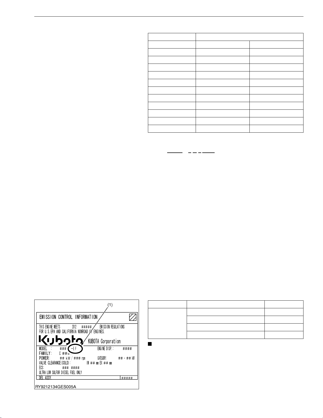
of compliance with the original E4B design and EPA or other applicable regulations.Please refer to the emission label
located on the engine head cover to identify Output classification and Emission Control Information. E4B engines are
identified with "EF" at the end of the Model designation, on the US EPA label. Please note: E4B is not marked on the
engine.
Category (1) Engine output classification EPA regulation
Less than 19 kW Tier 4
EF
• "E4B" engines are identified with "EF" at the end of the
Model designation, on the US EPA label.
"E4B" designates some Interim Tier 4 / Tier 4 models,
depending on engine output classification.
From 19 to less than 56 kW Interim Tier 4
From 56 to less than 75 kW Interim Tier 4
From 75 to less than 130 kW Interim Tier 4
RY9212148GEG0003US0
G-3
Page 25
KX080-4, WSM
KiSC issued 08, 2015 A
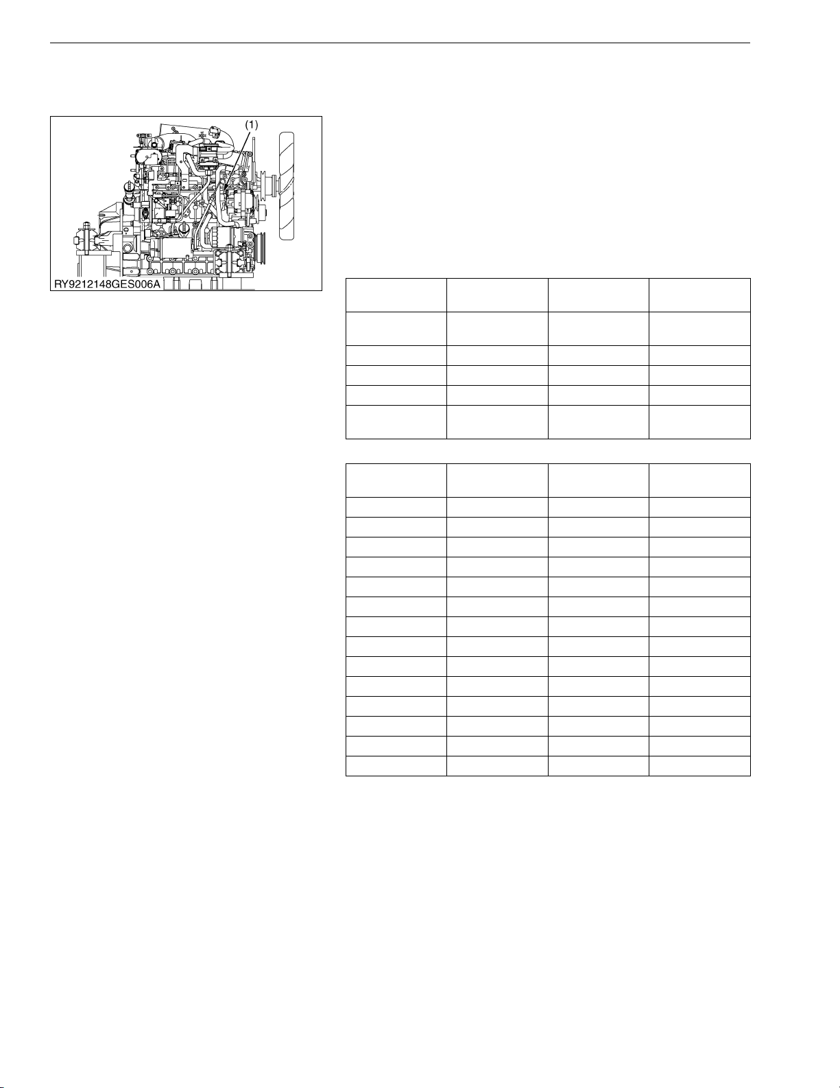
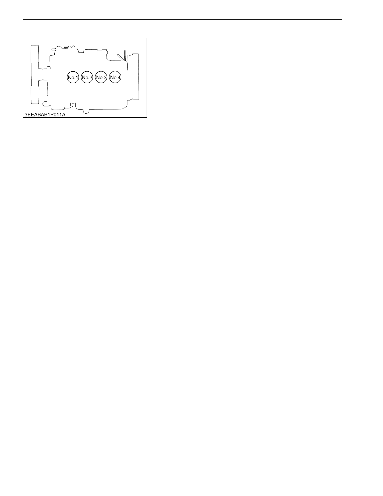
[3] CYLINDER NUMBER
GENERAL
You can see the cylinder numbers of KUBOTA diesel engine in
the figure.
The sequence of cylinder numbers is No.1, No.2, No.3 and No.4
and it starts from the gear case side.
RY9212134GEG0005US0
G-4
Page 26
KX080-4, WSM
KiSC issued 08, 2015 A
3. MUFFLER FULL ASSEMBLY IDENTIFICATION
[1] PART NUMBER AND SERIAL NUMBER
Diesel Particulate Filter (hereinafter referred to as the "DPF")
Muffler Full Assembly Serial Number
The DPF muffler full assembly serial number is an identified
number for the DPF muffler full assembly.
It shows the month and year of manufacture as below.
Year of manufacture
Alphabet or
Number
1 2001 F 2015
2 2002 G 2016
3 2003 H 2017
4 2004 J 2018
5 2005 K 2019
6 2006 L 2020
7 2007 M 2021
8 2008 N 2022
9 2009 P 2023
A 2010 R 2024
B 2011 S 2025
C 2012 T 2026
D 2013 V 2027
E 2014
Year
Alphabet or
Number
GENERAL
Yea r
Month of manufacture
Month DPF Muffler Full Assembly Lot Number
January A0001 to A9999 B0001 to BZ999
February C0001 to C9999 D0001 to DZ999
March E0001 to E9999 F0001 to FZ999
April G0001 to G9999 H0001 to HZ999
May J0001 to J9999 K0001 to KZ999
June L0001 to L9999 M0001 to MZ999
July N0001 to N9999 P0001 to PZ999
August Q0001 to Q9999 R0001 to RZ999
September S0001 to S9999 T0001 to TZ999
October U0001 to U9999 V0001 to VZ999
November W0001 to W9999 X0001 to XZ999
December Y0001 to Y9999 Z0001 to ZZ999
* Alphabetical letters "I" and "O" are not used.
(a)L(b)
(c)
e.g. C
(1) DPF Muffler Full Assembly Part Number and Serial Number
(a) Year: C indicates 2012
(b) Month: L or M indicates June
(c) Lot Number: (0001 to 9999 or A001 to Z999)
0019
RY9212148GEG0004US0
G-5
Page 27

KX080-4, WSM
KiSC issued 08, 2015 A
GENERAL
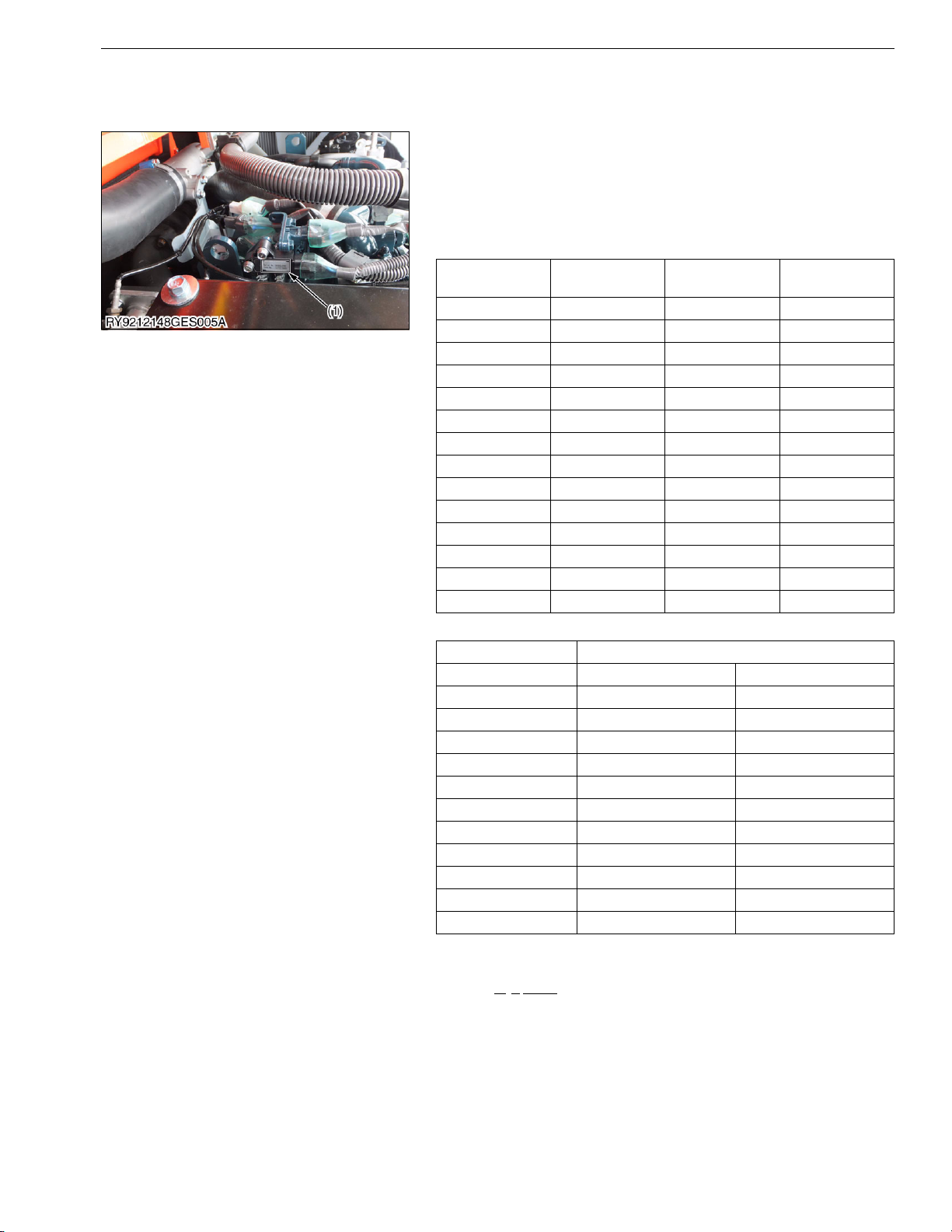
You must keep the records of the filter comp (DPF) part number
and serial number before you remove the DPF for cleaning.
(1) Body (DPF Outlet) Part Number and
Serial Number
(2) Filter Comp (DPF) Part Number and
Serial Number
(3) Catalyst (DOC) Part Number and
Serial Number
RY9212148GEG0005US0
G-6
Page 28
KX080-4, WSM
KiSC issued 08, 2015 A
4. GENERAL PRECAUTIONS
Whenever performing maintenance on the machine, always
read the Safety Precautions in this manual and the Operator's
Manual carefully, become familiar with them and perform the work
safely.
Before performing any maintenance on the machine, make sure
it is sufficiently clean and choose a sufficiently clean location to
perform any disassembly.
Before performing maintenance on the machine, always
disconnect the negative battery cable first.
Whenever a special tool is required, use the special tool that
KUBOTA recommends. Make any special tools that are not used
very frequently according to the diagrams in this manual.
Always use genuine KUBOTA parts to maintain the
performance and safety characteristics of the machine.
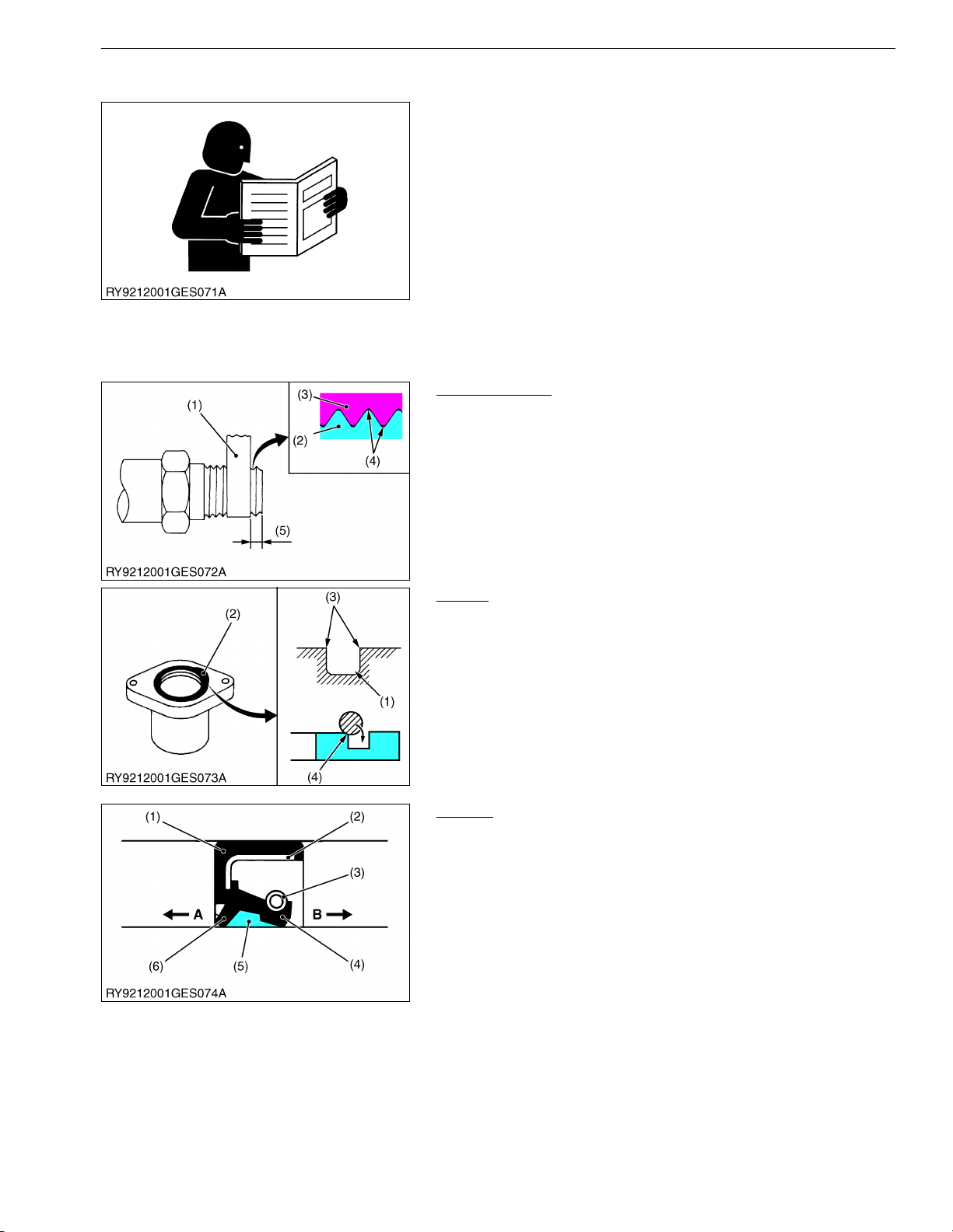
Plumber's Tape
• Wrap plumber's tape on the threads before tightening taper
couplings. After wrapping (2 wraps) the plumber's tape, tighten
to the specified torque. Once the coupling is tightened, do not
loosen it as this will cause an oil leak.
(1) Plumber's Tape
(2) External Thread
(3) Internal Thread
GENERAL
RY9212001GEG0011US0
(4) Gap
(5) Leave 1 to 2 Threads
RY9212001GEG0012US0
O-Ring
• Clean the groove the O-ring goes in and remove any burrs.
Apply grease on the O-ring when inserting it in the groove.
(Except floating seals)
• When putting the O-ring in the groove, be careful as it is easy at
the very end to twist the O-ring against the inside of the groove.
If it gets twisted, roll it gently with your fingertip to untwist it.
(1) O-Ring Groove
(2) O-Ring
(3) Check for Burrs
(4) If the Ring Touches This Corner, It
Will Twist
RY9212001GEG0013US0
Oil Seal
• Do not face the lip of the oil seal in the wrong direction. Face the
main lip toward the material to be sealed.
• After oil seals are replaced, apply grease to the moving parts
around the lip to prevent the dry surfaces from wearing against
each other when the engine is started. If the seal has a dust lip,
fill the gap between the lips with grease.
• As a general rule, use a press to insert the oil seal in place.
If that is not possible, use an appropriate tool to gently and
evenly tap it into place, taking care that it does not go in at a
slant. Press the seal all the way so it seats in the boss.
(1) Gasket
(2) Metal Ring
(3) Spring
(4) Main Lip
(5) Grease
(6) Dust Lip
A : Air (Outside)
B : Hydraulic Chamber (Inside)
RY9212001GEG0014US0
G-7
Page 29
KX080-4, WSM
KiSC issued 08, 2015 A
GENERAL
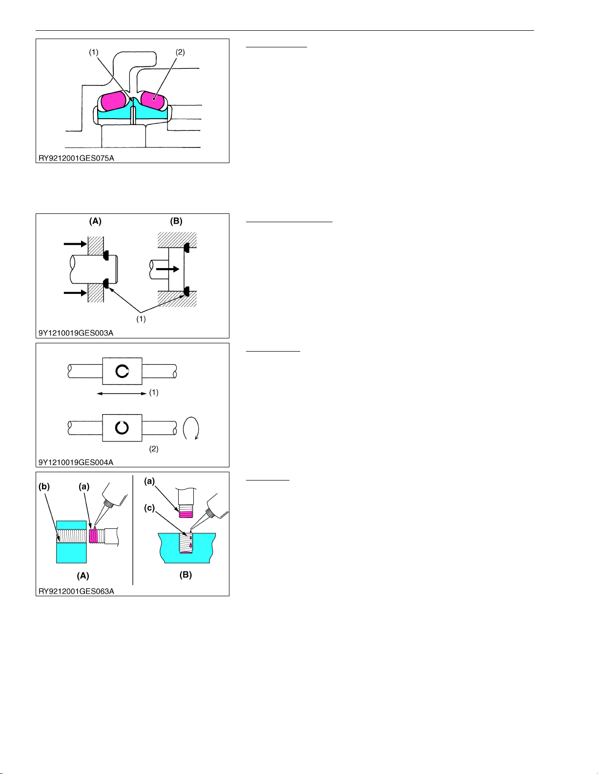
Floating Seal
• Be sure to wipe off any oil from the O-ring or surfaces that touch
the O-ring. (For wheel motors, apply a light film)
• When putting an O-ring into a floating seal, make sure the
O-ring does not twist.
• Apply a light film of oil to surrounding surfaces when working to
get the floating seal with O-ring in place; take care that the
surrounding surfaces, O-ring and housing are parallel with each
other.
• After getting the seal in place, turn the engine over 2 or 3
revolutions, to both create a film of oil on surrounding surfaces
and to properly seat the face of the seal.
(1) Surrounding Surfaces (2) O-Ring
RY9212001GEG0015US0
Snap Ring Related
• When installing external or internal snap rings, orient them as
shown in the diagram so the angled side faces the direction of
force.
(1) Position so the Angled Part
Receives the Force
(A) External
(B) Internal
RY9212001GEG0016US0
Spring Pins
• When driving a spring pin, face the split in the direction that
receives the force, as shown in the diagram.
(1) With Lateral Movement (2) With Rotational Movement
RY9212001GEG0017US0
Adhesive
• Clean and dry the area where adhesive will be applied with a
solvent so it is free of moisture, oil and dirt.
• Apply adhesive all around the threads of the bolt except the first
set of threads at the tip and fill the grooves between the threads.
If the threads or the grooves are large, adjust the amount of
adhesive accordingly and apply it all around the bolt hole as
well.
(A) Bolt Through-Hole (Nut)
(B) Pocket Bolt Hold
(Capsule Shape, etc.)
(a) Apply Here
(b) Do Not Apply
(c) Drip On
RY9212001GEG0018US0
G-8
Page 30
KX080-4, WSM
KiSC issued 08, 2015 A
GENERAL
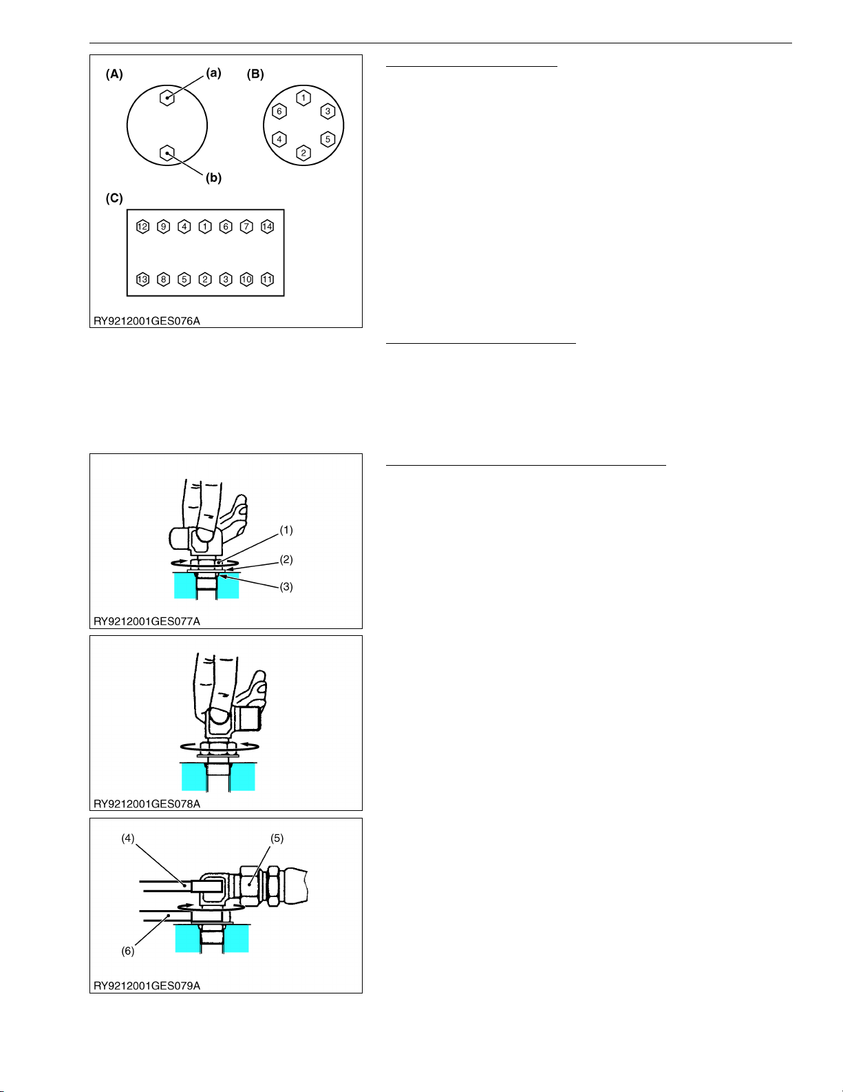
Tightening Bolts and Nuts
• Tighten bolts and nuts to their specified torque.
• Tighten nuts and bolts alternately top/bottom (a) (b), left/right so
the torque is distributed evenly.
(A) Top/Bottom Alternately
(B) Across Diagonally
(C) Diagonally Across the Center
RY9212001GEG0019US0
Assembling Hydraulic Hoses
• Tighten to their specified torque.
• Before assembling, wipe the inside of metal fittings clean of any
dirt.
• After assembly, put the fitting under normal pressure and check
that it does not leak.
RY9212001GEG0020US0
Elbow with Male Seat Assembly Procedure
When assembling an elbow with male seat, adhere to the
following procedures to prevent deformation of O-rings and leaks.
1. Connecting to Valves
• Clean the blow with male seat and the surface of the seal
opposite and mount with the lock-nut on top.
• Finger tighten till it touches the washer.
2. Positioning
• Turn the mouth of the elbow back so it faces the right
direction. (not back over 1 turn)
3. Fasten
• Tighten the lock-nut to the specified torque with a wrench.
(1) Lock-Nut
(2) Washer
(3) Seal (O-Ring)
(4) Wrench for Holding
(5) Hose
(6) Torque Wrench for Tightening
RY9212001GEG0021US0
G-9
Page 31

KX080-4, WSM
KiSC issued 08, 2015 A
GENERAL
Installing and Removing Quick Couplings
• To remove a quick hose coupling, push the fitting in the direction
of the arrow and pull on the plastic part in the opposite direction.
• To attach a quick coupler, push it in firmly in the direction of the
arrow. Then check that it will not pull off.
(1) Plastic Part (2) Fitting
RY9212001GEG0022US0
Connecting the face sealing (ORS) type hose
1. Remove the protective cap from the adapter and make sure the
O-ring is installed in its groove. (If the O-ring is missing, fit the
specified-size in position.)
2. Shift the hose's cap nut in the direction of arrow until the O-ring
contact face stretched out of the cap nut.
3. Bring the hose's O-ring contact face in close contact with the
joint's O-ring.
Make sure they do not come off each other.
4. Tighten up the cap nut to the specified torque.
(1) Protective cap
RY9212038GEG0005US0
G-10
Page 32

KX080-4, WSM
IMPORTANT
KiSC issued 08, 2015 A
GENERAL
5. HANDLING PRECAUTIONS FOR ELECTRICAL PARTS AND WIRING
Follow the precautions below for handling electrical parts and
wiring to ensure safety and prevent damage to the machine and
nearby equipment.
• Inspect electrical wiring for damage and/or loose
connections.
• Do not alter or rewire any electrical parts or wiring.
• Always remove the negative battery cable first when
disconnecting the battery and attach the positive cable first
when connecting it.
(1) Battery Cable (-) Side (2) Battery Cable (+) Side
RY9212001GEG0023US0
[1] WIRING
• Tighten wiring terminals securely.
(1) Correct (Tightened Securely) (2) Incorrect (Poor Contact if Loose)
RY9212001GEG0024US0
• Keep wiring away from hazards.
(1) Hazardous Positioning
(2) Wiring Position (Wrong)
(3) Wiring Position (Right)
(4) Hazardous Position
RY9212001GEG0025US0
• Immediately repair or replace old or damaged wiring.
(1) Damaged
(2) Torn
(3) Electrical Tape
RY9212001GEG0026US0
G-11
Page 33

KX080-4, WSM
KiSC issued 08, 2015 A
GENERAL
• Insert grommet securely.
(1) Grommet (A) Correct
(B) Incorrect
RY9212001GEG0027US0
• Clamp wiring securely but do not damage wires with the clamp.
(1) Clamp (Spiral Clamp Around Wire)
(2) Wire
(3) Clamp
(4) Welding Mark
RY9212001GEG0028US0
• Clamp wiring so it is not twisted, pulled too tight or sag too
much. However, moving parts may require play in the wiring.
(1) Wire
(2) Clamp
(A) Correct
(B) Incorrect
RY9212001GEG0029US0
• Do not pinch or bind wiring when installing parts.
(1) Wire (A) Incorrect
RY9212001GEG0030US0
• After wiring, double-check terminal protectors and clamps
before connecting battery cables.
(1) Cover (Install Covers Securely)
RY9212001GEG0031US0
G-12
Page 34

KX080-4, WSM
KiSC issued 08, 2015 A
GENERAL
• Do not modify harnesses. The diameter of wires in each
harness is determined after calculating its capacity.
• Modifying harnesses may cause a malfunction or a fire.
[2] FUSES
[3] CONNECTOR
(A) Wiring Diagram
(B) Diagram of Modification
(a) Standard Wiring
(b) Modified Wiring
RY9212038ELS0008US0
• Always use fuses of the specified capacity.
Never use over or undersized fuses.
• Never use copper or steel wire in place of a fuse.
• Do not install accessories such as work lights, radios, etc., if
your machine does not have an auxiliary circuit.
• Do not install accessories as they will exceed the capacity of
fuses.
(1) Fuse
(2) Fusible Link
(3) Slow-Blow Fuse
RY9212001GEG0032US0
Connectors
The terminals of female connector are numbered from #1 on the
top right when facing it.
Male terminals are numbered from #1 on the top left.
(A) Female connector terminals (B) Male connector terminals
RY9212038ELS0010US0
• Press the lock to disconnect locking connectors.
(A) Push
RY9212001GEG0033US0
G-13
Page 35

KX080-4, WSM
KiSC issued 08, 2015 A
GENERAL
• Hold the connectors when separating them.
• Do not pull on the wire harness to separate the connectors.
(A) Correct (B) Incorrect
RY9212001GEG0034US0
Pull on the harness from the connector and make sure the
harness does not come off. (Pull with 3 kgf (30 N, 7 lbf) or less of
force)
(A) Pull (B) Loosened Crimping
RY9212038ELS0011US0
• Straighten bent prongs and make sure none are sticking out or
missing.
• Remove corrosion from terminals with sandpaper.
(1) Missing Terminal
(2) Bent Prong
(3) Sandpaper
(4) Corrosion
RY9212001GEG0035US0
• Do not touch the terminals of connectors with bare hands.
(A) Do not touch
RY9212038ELS0012US0
• Female connectors must not be spread too far open
(A) Correct (B) Incorrect
RY9212001GEG0036US0
G-14
Page 36

KX080-4, WSM
CAUTION
KiSC issued 08, 2015 A
GENERAL
• The plastic covers of connectors must cover them completely.
(1) Cover (A) Correct
(B) Incorrect
RY9212001GEG0037US0
[4] WASHING THE MACHINE WITH A HIGH-PRESSURE WASHER
Using a high-pressure washer incorrectly can lead to personal
injury and/or damage, break or cause parts of the machine to fail,
so use the power washer properly according to its operator's
manual and labels.
• Stand at least 2.0 meters from the machine and adjust the
nozzle for a wide spray so it does not cause any damage.
If you blast the machine with water or wash it from too
close a distance,
1. It may cause a fire due to damaged or cuts in the insulation
of electrical wiring.
2. An injury may result if hydraulic oil gushes out under high
pressure, due to damaged hydraulic hoses.
3. It may damage, break or cause parts of the machine to fail.
(Ex.)
(1) Stickers or labels may come off
(2) Electrical parts or the engine may fail due to water in them.
(3) Damage glass, resins, etc. or the rubber of oil seals.
(4) Tear off paint or the film from plating
(1) Do Not Blast with Water
(2) Never Wash from Too Close
(A) Blasting
(B) Wide Spray
(C) Less Than 2.0 m (80 in.)
(D) Over 2.0 m (80 in.)
RY9212001GEG0038US0
G-15
Page 37

KX080-4, WSM
KiSC issued 08, 2015 A
GENERAL
6. TIGHTENING TORQUES
[1] TORQUES FOR GENERAL USE NUTS AND BOLTS
Screws, bolts and nuts whose tightening torques are not specified in this Workshop Manual should be
tightened according to the table below.
Indication on top of bolt
Indication on top of nut
Material of opponent part Ordinariness Aluminum Steel Aluminum Steel
Unit N·m kgf·m lbf·ft N·m kgf·m lbf·ft N·m kgf·m lbf·ft N·m kgf·m lbf·ft N·m kgf·m lbf·ft
7.9
0.8
M6
M8
M10
M12
M14
M16
M18
M20
to
9.3
18
to
20
40
to
45
63
to
72
108
to
125
16
to
191
246
to
284
334
to
392
to
0.95
1.8
to
2.1
4.0
to
4.6
6.4
to
7.4
11
to
12.8
7
17
to
19.5
25
to
29
34
to
40
No-grade or 4T 7T 9T
No-grade or 4T
5.8
7.9
0.8
5.8
9.81
1.0
7.24
7.9
0.8
5.8
12.3
to
to
to
to
to
to
to
to
to
to
6.8
8.8
0.9
6.5
13
17
1.7
to
to
15
19
32
29
to
to
33
34
47
to 53–––
79.6
to
–––
92.5
123
to
–––
141
181
to
–––
209
246
to
–––
289
to
2.0
3.2
to
3.5
13
to
14
24
to
25
11. 2
24
to
27
48
to
55
78
to
90
124
to
147
197
to
225
275
to
318
368
to
431
1.15
2.4
to
2.8
4.9
to
5.7
7.9
to
9.2
12.6
to
15
20
to
23
28
to
32.5
37.5
to
44
8.31
18
to
20
36
to
41
58
to
66
91.2
to
108
145
to
166
203
to
235
272
to
318
8.8
0.9
18
1.8
to
to
20
2.1
40
4.0
to
to
44
4.5
63
6.4
to
to
72
7.4
––
–––
–––
–––
to
6.5
14.2
13
30
to
to
15
34
29
61
to
to
32
70
47
103
to
to
53
117
167
–
to
196
260
to
304
344
to
402
491
to
568
RY9212032GEG0001US0
6T
1.25
to
1.45
3.0
to
3.5
6.2
to
7.2
10.5
to
12
17
to
20
26.5
to
31
35
to
41
50
to
58
9.05
to
10.4
22
to
25
45
to
52
76
to
86.7
123
to
144
192
to
224
254
to
296
362
to
419
G-16
Page 38

KX080-4, WSM
KiSC issued 08, 2015 A
[2] TORQUE FOR HYDRAULIC HOSE FITTINGS
(1) Torque for Hydraulic Hose Fittings
Union nut (metal seal type) Union nut (ORS type)
7.8 to 11.8 N·m
1/8
1/4
3/8
1/2
3/4
1 - 1/4
0.8 to 1.2 kgf·m
5.7 to 8.7 lbf·ft
24.5 to 29.2 N·m
2.5 to 3.0 kgf·m
18.1 to 21.7 lbf·ft
37.2 to 42.1 N·m
3.8 to 4.3 kgf·m
27.5 to 31.1 lbf·ft
58.8 to 63.7 N·m
6.0 to 6.5 kgf·m
43.4 to 47.0 lbf·ft
117.6 to 127.4 N·m
12.0 to 13.0 kgf·m
86.8 to 94.0 lbf·ft
220.5 to 230.3 N·m
22.5 to 23.5 kgf·m
162.7 to 169.8 lbf·ft
––
35.2 to 43.1 N·m
9/16UNF
11/16UNF
13/16UNF
1-14UNS
––
3.6 to 4.4 kgf·m
26.0 to 31.8 lbf·ft
60.0 to 73.5 N·m
6.1 to 7.5 kgf·m
44.3 to 54.2 lbf·ft
70.6 to 86.2 N·m
7.2 to 8.8 kgf·m
52.1 to 63.6 lbf·ft
105.8 to 129.4 N·m
10.8 to 13.2 kgf·m
78.0 to 98.4 lbf·ft
GENERAL
RY9212148GEG0006US0
(2) Torques of Lock-Nuts for Elbows with Male Seats and Adaptors with
O-rings (Straight Threads)
15.0 to 16.5 N·m
Tightening torque
(1) Lock-nut
(2) Washer
1/8
1/4
3/8
1/2
3/4, 1
1-1/4
7/8 - 14UNF
(3) Seal (O-ring)
1.5 to 1.7 kgf·m
11.1 to 12.2 lbf·ft
24.5 to 29.4 N·m
2.5 to 3.0 kgf·m
18.1 to 21.7 lbf·ft
49.0 to 53.9 N·m
5.0 to 5.5 kgf·m
36.1 to 39.8 lbf·ft
58.8 to 63.7 N·m
6.0 to 6.5 kgf·m
43.4 to 47.0 lbf·ft
117.6 to 127.4 N·m
12.0 to 13.0 kgf·m
86.8 to 94.0 lbf·ft
220.5 to 230.3 N·m
22.5 to 23.5 kgf·m
162.8 to 170.0 lbf·ft
55.9 to 60.8 N·m
5.7 to 6.2 kgf·m
41.2 to 44.8 lbf·ft
RY9212148GEG0007US0
G-17
Page 39

KX080-4, WSM
KiSC issued 08, 2015 A
[3] HOSE CLAMP SCREW TORQUE
Type 1
GENERAL
Tightening torque
10- 14 6C040-58721
12- 16 09318-89016
19- 25 09318-89024
31- 40 09318-89039
36- 46 09318-89045
44- 53 09318-89052
51- 59 09318-89058
86- 96 RD809-42241
2.5 to 3.4 N·m
25 to 35 kgf·cm
1.8 to 2.5 lbf·ft
2.5 to 3.4 N·m
25 to 35 kgf·cm
1.8 to 2.5 lbf·ft
2.5 to 3.4 N·m
25 to 35 kgf·cm
1.8 to 2.5 lbf·ft
2.5 to 3.4 N·m
25 to 35 kgf·cm
1.8 to 2.5 lbf·ft
2.5 to 3.4 N·m
25 to 35 kgf·cm
1.8 to 2.5 lbf·ft
3.9 to 4.9 N·m
40 to 50 kgf·cm
2.9 to 3.6 lbf·ft
3.9 to 4.9 N·m
40 to 50 kgf·cm
2.9 to 3.6 lbf·ft
2.5 to 3.4 N·m
25 to 35 kgf·cm
1.8 to 2.5 lbf·ft
RY9212001GEG0045US0
G-18
Page 40

KX080-4, WSM
KiSC issued 08, 2015 A
GENERAL
Type 2
Tightening torque
13- 20 RB101-63631
15- 25 RC101-64581
19- 28 R1401-63211
22- 32 R1401-63151
26- 38 68311-72821
32- 44 RD411-63821
44- 56 35820-15181
50- 65 RC401-63191
58- 75 36919-04591
60- 80 RD809-63101
68- 85 RD809-63061
77- 95 69284-63171
2.5 to 3.4 N·m
25 to 35 kgf·cm
1.8 to 2.5 lbf·ft
4.9 to 5.9 N·m
50 to 60 kgf·cm
3.6 to 4.3 lbf·ft
4.9 to 5.9 N·m
50 to 60 kgf·cm
3.6 to 4.3 lbf·ft
4.9 to 5.9 N·m
50 to 60 kgf·cm
3.6 to 4.3 lbf·ft
4.9 to 5.9 N·m
50 to 60 kgf·cm
3.6 to 4.3 lbf·ft
4.9 to 5.9 N·m
50 to 60 kgf·cm
3.6 to 4.3 lbf·ft
4.9 to 5.9 N·m
50 to 60 kgf·cm
3.6 to 4.3 lbf·ft
4.9 to 5.9 N·m
50 to 60 kgf·cm
3.6 to 4.3 lbf·ft
4.9 to 5.9 N·m
50 to 60 kgf·cm
3.6 to 4.3 lbf·ft
4.9 to 5.9 N·m
50 to 60 kgf·cm
3.6 to 4.3 lbf·ft
4.9 to 5.9 N·m
50 to 60 kgf·cm
3.6 to 4.3 lbf·ft
4.9 to 5.9 N·m
50 to 60 kgf·cm
3.6 to 4.3 lbf·ft
RY9212001GEG0046US0
G-19
Page 41

KX080-4, WSM
KiSC issued 08, 2015 A
7. OIL AND WATER CAPACITY TABLE
Item KX080-4 Notes
Engine oil (when filter changed) 9.7 L (2.6 U.S.gal) API type, CJ-4
Coolant 10.5 L (2.77 U.S.gal)
Reserve tank 1.3 L (0.34 U.S.gal)
Fuel (full) 115 L (30.4 U.S.gal) JIS #3 diesel
Hydraulic oil
Travel motor 1.35 L (0.36 U.S.gal) Gear oil SAE#90 (API GL-4)
Idler assy 80 ml (4.88 cu.in.)
Carrier rollers 80 ml (4.88 cu.in.)
Grease – EP2
Total volume (Std. spec.) 146 L (38.6 U.S.gal)
Inside tank (gauge middle) 75 L (20.0 U.S.gal)
Antifreeze Kubota LLC-N-50F
Mixture ratio 50%
Tellus oil S2M46
Engine oil SAE #30CD (monograde)Track rollers 80 ml (4.88 cu.in.)
RY9212158GEG0001US0
GENERAL
G-20
Page 42

KX080-4, WSM
KiSC issued 08, 2015 A
8. MAINTENANCE INTERVALS
GENERAL
No. Check points Measures
check Daily check
1 Coolant
2 Fuel check Daily check
3 Engine oil
4 Hydraulic oil
Bucket and
bucket link pin
/ Dozer angle
Grease front
5
attachments
6 Radiator and oil cooler check Daily check
7 Washer liquid check Daily check
8 Engine and electrical wiring check Daily check
9 Water separator drain
10 Fuel tank drain
11 Battery condition check
Greasing swing bearing
12
teeth
13 V-belt tension
14 Radiator hoses and clamps
Air filter
15
element
16 Greasing swing ball bearing –
Fuel filter cartridge replace
17
18 Engine oil filter replace
19 Drive unit oil change
Hydraulic return filter
20
cartridge
Hydraulic suction filter
21
element
Filter in the pilot hydraulic
22
system
23 Injector tip check
pin and angle
cylinder boss
Boom swing
fulcrum
Others –
Outer
element
Inner element replace
change
check Daily check
change
check Daily check
change
check Daily check
adjust
check
replace
clean
replace
replace
replace
50 100 150 200 250 300 350 400 450 500 550 600 650 700 750 800 1000
– Daily check
–
–
Hour meter indication
Interval
every
2 years
every
500 hrs
every
1000 hrs
every
100 hrs
every
250 hrs
every
50 hrs
every
50 hrs
every
50 hrs
every
50 hrs
every
200 hrs
every
200 hrs
every
2 years
every
200 hrs
every
1000 hrs
every
1000 hrs
every
hrs
200
every
500 hrs
every
500 hrs
every
500 hrs
every
500 hrs
every
1000 hrs
every
1000 hrs
every
1500 hrs
*1
*2
@replace
*2
*2
@
*4
*4
*4 @
G-21
Page 43

KX080-4, WSM
KiSC issued 08, 2015 A
GENERAL
No. Check points Measures
24 Oil separator element replace
25 EGR cooler check
26 Front idler and track roller oil change
27 Alternator and starter motor check
28 EGR system check
29 Turbo charger check
30 DPF clean
Boost sensor and AFS
31
(Air flow sensor)
32 Condition of DPF muffler check
DPF differential pressure
33
sensor and piping for gas
leak
DPF exhaust gas
34
temperature sensor
35 EGR and piping for gas leak check
36 Radiator system rinse
37 Fuel line and intake air line
Closed breather related
38
rubber piping
DPF differential pressure
39
sensor rubber piping (Front
and back)
Suction pipe downstream the
40
AFS
Boost sensor pressure
41
rubber piping
42 EGR cooler hose replace
check
check
check
check
replace
replace
replace
replace
replace
Hour meter indication
50 100 150 200 250 300 350 400 450 500 550 600 650 700 750 800 1000
Interval
every
1500 hrs
every
1500 hrs
every
2000 hrs
every
2000 hrs
every
3000 hrs
every
3000 hrs
every
3000 hrs
every
1 year
every
1 year
every
1 year
every
1 year
every
1 year
every
2 years
every
200 hrs
every
2 years
every
2 years
every
2 years
every
2 years
every
2 years
every
y
ears
2
*4 @
*4
*4
*4
*4
*4
*4
*4
*4
*4
*4
*4
*4
@
*3
*4
*4
*4
*4
*4
G-22
Page 44

KX080-4, WSM
IMPORTANT
NOTE
IMPORTANT
KiSC issued 08, 2015 A
GENERAL
Air conditioner
No. Check points Measures
clean
1 Air filter
replace
2 Air-conditioner condenser check
Air-conditioner pipes and
3
hose
4 Refrigerant (gas) check
check
replace
50 100 150 200 250 300 350 400 450 500 550 600 650 700 750 800 1000
Hour meter indication
Interval
every
200 hrs
every
1000 hrs
every
200 hrs
every
1year
every
2 years
service as
required
*2
*2
*4
• : First operation
• *1 : When using a hydraulic hammer, change hydraulic oil and return filter according to the table on
"Hydraulic Oil Change (Including Exchange of the Suction Filter in the Hydraulic Tank) under "EVERY
1000 SERVICE HOURS" in the chapter "REGULAR CHECKS AND MAINTENANCE WORK".
*2 : Clean and replace the air filter more frequently if used under dusty conditions. When the filter is very
dirty from dusty conditions, replace the filter.
*3 : Replace only if necessary.
*4 : Consult your local KUBOTA Dealer for this service.
• The items listed above (@ marked) are registered as emission related critical parts by KUBOTA in the
U.S.EPA nonroad emission regulation. As the engine owner, you are responsible for the performance of
the required maintenance on the engine according to the above instruction. Please see the Warranty
Statement in detail.
RY9212158GEG0002US0
Engine Oil:
• Oil used in the engine should have an American Petroleum Institute (API) service classification and
Proper SAE Engine Oil according to the ambient temperatures.
Above 25 °C (77 °F) SAE30 or SAE 10W-30, SAE 15W-40
0 to 25 °C (32 to 77 °F) SAE20 or SAE 10W-30, SAE 15W-40
Below 0 °C (32 °F) SAE10W or SAE 10W-30, SAE 15W-40
• Refer to the following table for the suitable API classification engine oil and the fuel.
Fuel used
Ultra Low Sulfur Fuel [< 0.0015 % (15 ppm)] CJ-4
Engine oil classification (API classification)
Oil class of engines except external DPF
Fuel:
• Use the ultra low sulfur diesel fuel only [below 0.0015 % (15 ppm)] for these engines.
• Cetane number of 45 minimum. Cetane number greater than 50 is preferred, especially for temperatures below
-20 °C (-4 °F) or elevations above 1500 m (5000 ft).
• Diesel fuels specified to EN 590 or ASTM D975 are recommended.
• No. 2-D is a distillate fuel of lower volatility for engines in industrial and heavy mobile service. (SAE J313 JUN87)
• Indicated capacities of water and oil are manufacture's estimate.
• If you use different fuel or engine oil, the cleaning interval of the DPF (3000 hours) can't be secured and
the DPF will be clogged for a shorter time than expected.
• Filters must trap fuel and lubricant sulfate additives (Zn, Pb, Na, K, Ca, Mg, Cu, Ba, P, etc.) as ash during
combustion. Fuel must be controlled carefully to prevent the additives being mixed into fuel such as fuel
tank anti-oxidants, water remover, anti-freeze and so on.
RY9212158GEG0003US0
G-23
Page 45

1 MACHINE BODY
KiSC issued 08, 2015 A
Page 46

SERVICING
KiSC issued 08, 2015 A
CONTENTS
1. FRONT ........................................................................................................................................ 1-S1
[1] BOOM ASSEMBLY/DISASSEMBLY .....................................................................................1-S1
[2] TABLE OF DIMENSIONS .....................................................................................................1-S3
(1) Bucket..............................................................................................................................1-S3
(2) Front Pin ..........................................................................................................................1-S4
(3) Front Bushings ................................................................................................................1-S5
(4) Arm ..................................................................................................................................1-S6
(5) Blade ...............................................................................................................................1-S7
2. SWIVEL FRAME..........................................................................................................................1-S8
[1] WEIGHT ASSEMBLY/DISASSEMBLY ................................................................................. 1-S8
[2] CABIN REMOVAL AND MOUNTING ....................................................................................1-S8
[3] FUEL TANK ASSEMBLY/DISASSEMBLY ..........................................................................1-S11
[4] HYDRAULIC OIL TANK ASSEMBLY/DISASSEMBLY........................................................1-S14
[5] ASSEMBLY/DISASSEMBLY OF ENGINE RELATED COMPONENTS..............................1-S16
(1) DPF Muffler ...................................................................................................................1-S16
(2) Engine ...........................................................................................................................1-S18
[6] ASSEMBLING OPERATING LEVERS ................................................................................1-S21
(1) Travel Lever...................................................................................................................1-S21
(2) Blade Lever ...................................................................................................................1-S21
(3) Limit Switch ...................................................................................................................1-S21
3. TRACK FRAME .........................................................................................................................1-S22
[1] SWIVEL BEARING ASSEMBLY/DISASSEMBLY ............................................................... 1-S22
[2] TRACK ................................................................................................................................1-S23
(1) Assembly/Disassembly of the Rubber Track.................................................................1-S23
(2) Assembly/Disassembly of Iron Tracks...........................................................................1-S24
(3) Steel Track Removal/Installation Tools .........................................................................1-S27
[3] FRONT IDLER.....................................................................................................................1-S30
(1) Assembly/Disassembly of Front Idler ............................................................................1-S30
(2) Assembly/Disassembly of the Front Idler ......................................................................1-S30
[4] GREASE CYLINDER ..........................................................................................................1-S32
(1) Assembly/Disassembly of the Grease Cylinder............................................................. 1-S32
(2) Components ..................................................................................................................1-S32
[5] TENSIONER........................................................................................................................1-S33
(1) Tensioner Assembly/Disassembly................................................................................. 1-S33
[6] TRACK ROLLERS...............................................................................................................1-S34
(1) Track Roller Assembly/Disassembly .............................................................................1-S34
(2) Components ..................................................................................................................1-S34
[7] CARRIER ROLLERS...........................................................................................................1-S35
(1) Carrier Roller Assembly/Disassembly ...........................................................................1-S35
(2) Components ..................................................................................................................1-S3
TABLE OF DIMENSIONS ................................................................................................... 1-S36
[8]
(1) Rubber Track.................................................................................................................1-S36
(2) Steel Track ....................................................................................................................1-S36
(3) Idler Sprocket ................................................................................................................1-S37
(4) Carrier Rollers and Track Rollers .................................................................................. 1-S37
4. MEASURING MACHINE PERFORMANCE ..............................................................................1-S38
[1] MEASURING FRONT PERFORMANCE ............................................................................ 1-S38
(1) Measuring Swivel Gear Backlash..................................................................................1-S38
(2) Measuring Swivel Bearing Play ..................................................................................... 1-S39
5
Page 47

5. SWIVEL GEAR BACKLASH PERFORMANCE .........................................................................1-S40
KiSC issued 08, 2015 A
Page 48

KX080-4, WSM
CAUTION
KiSC issued 08, 2015 A
MACHINE BODY
1. FRONT
[1] BOOM ASSEMBLY/DISASSEMBLY
• Wear protective gear, such as a helmet, eye protection, etc., during assembly/disassembly.
• For group work, decide on signals for communication, make sure everyone understands and uses them
and be very careful about safety.
• Never put your finger in the pin hole when aligning the pin with the hole.
• When hoisting anything heavy, always determine its center of gravity before hoisting it.
• When working with a sling, use a cloth or the like in places that may be hit hard by the nylon sling.
RY9212148MBS0012US0
1. Lower the front to the ground.
Remove the AUX lines from each bracket and disconnect the
bucket cylinder hoses.
(1) AUX line (2) Bucket cylinder hose
RY9212148MBS0017US0
2. Suspend the arm cylinder temporarily and remove the pin on the
rod side.
Operate the crane and lower the arm cylinder onto a block on
top of the boom.
(1) Arm Cylinder (2) Block
RY9212148MBS0018US0
3. Suspend the arm and bucket temporarily with the crane, then
remove the linkage pin between the arm and the boom and then
remove the bucket and the arm.
Weight Approx. 510 kg (1120 lbs)
(1) Pin
RY9212148MBS0019US0
4. Set the end of the boom on the ground.
Suspend the boom cylinder temporarily and remove the pin on
the rod side.
Operate the crane and lower the boom cylinder onto a stand.
(1) Pin (2) Cylinder stand
RY9212148MBS0020US0
1-S1
Page 49

KX080-4, WSM
KiSC issued 08, 2015 A
MACHINE BODY
5. Remove all the arm cylinder and bucket cylinder hoses.
(1) Arm cylinder hose (2) Bucket cylinder hose
RY9212148MBS0021US0
6. Suspend the boom temporarily and remove the pin at the base
of the boom.
(1) Pin
RY9212148MBS0022US0
7. Operate the crane and remove the boom.
Boom weight Approx. 500 kg (1102 lbs)
RY9212148MBS0023US0
8. Perform the procedure in reverse for assembly.
RY9212148HYS0096US0
1-S2
Page 50

KX080-4, WSM
NOTE
KiSC issued 08, 2015 A
[2] TABLE OF DIMENSIONS
(1) Bucket
• Kubota Japan bucket
MACHINE BODY
No. KX080-4 No. KX080-4 No. KX080-4 No. KX080-4
(1)
(2)
(3)
(4)
(5)
(6)
600 mm
23.62 in.
620 mm
24.41 in.
328 mm
12.91 in.
200 mm
7.87 in.
44 mm
1.73 in.
20 mm
0.79 in.
(7)
(8)
(9)
(10)
(11)
(12)
105 mm
4.13 in.
120 mm
4.72 in.
60 mm
2.36 in.
538 mm
21.18 in.
902.5 mm
35.53 in.
7.5 mm
0.30 in.
1-S3
(13)
(14)
(15)
(16)
(17)
(18)
300 mm
11. 8 1 i n.
205 mm
8.07 in.
25 mm
0.98 in.
37.5 mm
1.48 in.
164.5 mm
6.48 in.
82 mm
3.23 in.
(19)
(20)
(21)
(22)
(23)
(24)
RY9212148MBS0033US0
462 mm
18.19 in.
90 mm
3.54 in.
22 mm
0.87 in.
14 mm
0.55 in.
222 mm
8.74 in.
111 m m
4.37 in.
Page 51

KX080-4, WSM
KiSC issued 08, 2015 A
(2) Front Pin
MACHINE BODY
Item
(1)
(2)
(3)
(4)
(5)
(6)
(7)
(8)
(9)
(10)
(11)
(12)
(13)
(14)
(15)
(16)
(17)
(18)
100 × 474 mm
3.94 × 18.66 in.
70 × 183 mm
2.76 × 7.20 in.
70 × 168 mm
2.76 × 6.61 in.
80 × 437 mm
3.15 × 17.20 in.
70 × 200 mm
2.76 × 7.87 in.
70 × 226 mm
2.76 × 8.90 in.
70 × 332 mm
2.76 × 13.07 in.
60 × 226 mm
2.36 × 8.90 in.
60 × 175 mm
2.36 × 6.89 in.
60 × 333 mm
2.36 × 13.11 in.
60 × 151 mm
2.36 × 5.94 in.
60 × 275 mm
2.36 × 10.83 in.
60 × 275 mm
2.36 × 10.83 in.
60 × 167 mm
2.36 × 6.57 in.
70 × 144 mm
2.76 × 5.67 in.
85 × 295 mm
3.35 × 11.61 in.
50 × 167 mm
1.97 × 6.57 in.
50 × 167 mm
1.97 × 6.57 in.
KX080-4
(Pin dia. X length)
• The pin usage limit is when the wear
exceeds 1.0mm (0.039 in.) from the
factory spec. from new.
(a) Pin diameter
(b) Length
RY9212158MBS0001US0
1-S4
Page 52

KX080-4, WSM
KiSC issued 08, 2015 A
(3) Front Bushings
MACHINE BODY
Item Point used
Swing bracket top
(1)
Swivel frame, vertical
Swing bracket bottom
(2) Cylinder
Swing bracket top
(3)
Cylinder
Swing bracket bottom
Swing bracket ends
(4)
Boom ends
Swing bracket right
(5)
Cylinder
Swing bracket left
(6) Cylinder
KX080-4
(I.D. X O.D. X Length)
100 × 115 × 64 mm
3.94 × 4.53 × 2.52 in.
100 × 115 × 110 mm
3.94 × 4.53 × 4.33 in.
100 × 115 × 61 mm
3.94 × 4.53 × 2.40 in.
70 × 82 × 65 mm
2.76 × 3.23 × 2.56 in.
70 × 82 × 45 mm
2.76 × 3.23 × 1.77 in.
70 × 82 × 65 mm
2.76 × 3.23 × 2.56 in.
70 × 82 × 36 mm
2.76 × 3.23 × 1.42 in.
80 × 95 × 80 mm
3.15 × 3.74 × 3.15 in.
80 × 95 × 80 mm
3.15 × 3.74 × 3.15 in.
70 × 82 × 49 mm
2.76 × 3.23 × 1.93 in.
70 × 82 × 75 mm
2.76 × 3.23 × 2.95 in.
70 × 82 × 49 mm
2.76 × 3.23 × 1.93 in.
70 × 82 × 75 mm
2.76 × 3.23 × 2.95 in.
Item Point used
(7) Arm ends
(8) Cylinder
(9) Cylinder
(10) Arm ends
(11) Bucket link
(12) Cylinder
(13) Arm ends
Bucket link
(14)
Cylinder
(15) Blade
(16) Blade
(17) Cylinder
(18) Angle fulcrum, vertical
KX080-4
(I.D. X O.D. X Length)
70 × 82 × 80 mm
2.76 × 3.23 × 3.15 in.
60 × 70 × 75 mm
2.36 × 2.76 × 2.95 in.
60 × 70 × 75 mm
2.36 × 2.76 × 2.95 in.
60 × 80 × 65 mm
2.36 × 3.15 × 2.56 in.
60 × 70 × 60 mm
2.36 × 2.76 × 2.36 in.
60 × 70 × 65 mm
2.36 × 2.76 × 2.56 in.
60 × 70 × 60 mm
2.36 × 2.76 × 2.36 in.
60 × 70 × 52 mm
2.36 × 2.76 × 2.05 in.
60 × 70 × 65 mm
2.36 × 2.76 × 2.56 in.
60 × 70 × 88 mm
2.36 × 2.76 × 3.46 in.
70 × 82 × 60 mm
2.76 × 3.23 × 2.36 in.
50 × 60 × 60 mm
1.97 × 2.36 × 2.36 in.
85 × 100 × 60 mm
3.35 × 3.94 × 2.36 in.
• The usage limit for bushings is when the wear exceeds 1.0 mm (0.039 in.) from the factory spec. from new.
RY9212158MBS0002US0
1-S5
Page 53

KX080-4, WSM
KiSC issued 08, 2015 A
Bushing shape
(4) Arm
MACHINE BODY
(A) Flanged bushing
(B) Normal bushing
(a) I.D.
(b) O.D.
(c) Length
RY9212148MBS0036US0
(A) Arm tip (B) Bucket link 1
No. KX080-4 No. KX080-4 No. KX080-4 No. KX080-4
(1)
(2)
(3)
(4)
(5)
260 mm
10.24 in.
1840 mm
72.44 in.
451 mm
17.76 in.
279 mm
10.98 in.
370 mm
14.57 in.
(6)
(7)
(8)
(9)
(10)
1745 mm
68.70 in.
403 mm
15.87 in.
428 mm
16.85 in.
13 mm
0.51 in.
188 mm
7.40 in.
1-S6
(11)
(12)
(13)
(14)
(15)
66 mm
2.60 in.
200 mm
7.87 in.
70 mm
2.76 in.
67 mm
2.64 in.
80 mm
3.15 in.
(16)
(17)
(18)
(19)
(20)
RY9212148MBS0037US0
70 mm
2.76 in.
200 mm
7.87 in.
76 mm
2.99 in.
70 mm
2.76 in.
Page 54

KX080-4, WSM
KiSC issued 08, 2015 A
(5) Blade
No. Item KX080-4
(a) I.D. X Length
(b) I.D. X Length
(c) Width
(d) Height
(e) Length
Tip height - plate
(f)
thickness
Distance between
(g)
supports
70 × 98 mm
2.76 × 3.86 in.
70 × 28 mm
2.76 × 1.10 in.
2200 mm
86.61 in.
500 mm
19.69 in.
1448 mm
57.01 in.
90 × t 16 mm
3.54 × t 0.63 in.
698 mm
27.48 in.
RY9212148MBS0038US0
MACHINE BODY
No. Item KX080-4 No. Item KX080-4
(a) I.D. X Length
(b) I.D. X Length
(c) I.D. X Length
(d) Width
(e) Height
(f) Length
70 × 98 mm
2.76 × 3.86 in.
70 × 28 mm
2.76 × 1.10 in.
85 × 289 mm
3.35 × 11.38 in.
2200 mm
86.61 in.
510 mm
20.08 in.
1754.5 mm
69.07 in.
(g) Tip height - plate thickness
(h) Distance between supports
(i) Cutting edge
(j) Cutting edge
(k) Cutting edge
(l) Cutting edge
1-S7
160 × t 15.9 mm
6.30 × t 0.63 in.
698 mm
27.48 in.
60 mm
2.36 in.
153 mm
6.02 in.
306 mm
12.05 in.
732 mm
28.82 in.
RY9212158MBS0003US0
Page 55

KX080-4, WSM
CAUTION
CAUTION
KiSC issued 08, 2015 A
2. SWIVEL FRAME
[1] WEIGHT ASSEMBLY/DISASSEMBLY
1. Remove the left and rear hoods.
It takes at least 2 people to remove the rear hood.
Rear hood weight Approx. 27 kg (60 lbs)
(1) Rear hood (2) Left hood
2. Remove the air cleaner.
(1) Air cleaner
MACHINE BODY
RY9212148MBS0039US0
RY9212148MBS0040US0
3. Remove the weight.
• Find its center of gravity and suspend it securely.
Tightening torque Weight
During installation, apply a threadlock. (Loctite 271)
Weight of the weight Approx. 1040 kg (2293 lbs)
(1) Weight
[2] CABIN REMOVAL AND MOUNTING
1. Remove the blower cover and AC panel, then remove the
blower hose, fuse box and AC connector.
(1) Blower cover
(2) AC panel
367.7 to 431.5 N·m
37.5 to 44.0 kgf·m
271.2 to 318.3 lbf·ft
RY9212148MBS0042US0
(3) Fuse box
RY9212148MBS0043US0
1-S8
Page 56

KX080-4, WSM
IMPORTANT
KiSC issued 08, 2015 A
MACHINE BODY
2. Disconnect the cabin harness and the washer harness.
(1) Cabin harness (2) Washer harness
RY9212148MBS0044US0
3. Suspend the cabin with the crane and remove the cabin
mounting bolts (nine) and nuts (two).
259.9 to 304.0 N·m
Bolt
Tightening torque
Nut
(1) Bolt (2) Nut
26.5 to 31.0 kgf·m
191.7 to 224.2 lbf·ft
107.9 to 127.4 N·m
11.0 to 13.0 kgf·m
79.6 to 94.0 lbf·ft
RY9212148MBS0045US0
4. Remove the cabin.
• Find its center of gravity and suspend it securely.
Cabin weight Approx. 230 kg (507 lbs)
(1) Cabin
RY9212148MBS0046US0
1-S9
Page 57

KX080-4, WSM
KiSC issued 08, 2015 A
Installation of cabin rubber vibration dampers
MACHINE BODY
(1) Nut
(2) Bolt
Tightening torque
Nut (1)
Bolt (2)
Nut (4)
Bolt (5)
(3) Rubber vibration damper
(4) Nut
107.9 to 127.4 N·m
11.0 to 13.0 kgf·m
79.6 to 94.0 lbf·ft
103.0 to 117.7 N·m
10.5 to 12.0 kgf·m
76.0 to 86.8 lbf·ft
39.2 to 45.1 N·m
4.0 to 4.6 kgf·m
28.9 to 33.3 lbf·ft
48.1 to 55.9 N·m
4.9 to 5.7 kgf·m
35.5 to 41.2 lbf·ft
(5) Bolt (6) Rubber vibration damper
RY9212148MBS0047US0
1-S10
Page 58

KX080-4, WSM
KiSC issued 08, 2015 A
[3] FUEL TANK ASSEMBLY/DISASSEMBLY
1. Remove the cover.
(1) Cover
2. After draining the fuel, remove the fuel hose.
(1) Water drain cock (2) Fuel hose
MACHINE BODY
RY9212148MBS0048US0
RY9212148MBS0049US0
3. Remove the electrical wiring and the fuel hose.
(1) Electrical wiring (2) Fuel hose
RY9212148MBS0050US0
4. Remove the band for mounting the fuel tank and then remove
the fuel tank.
(1) Fuel tank mounting band (2) Fuel tank
RY9212148MBS0051US0
1-S11
Page 59

KX080-4, WSM
NOTE
KiSC issued 08, 2015 A
Fuel hose circuit
MACHINE BODY
(1) Outside air
(2) Strainer (Eur. only)
(3) Fuel tank
(4) Water separator
(5) Fuel pump
(6) Fuel filter
(7) Engine
(8) Fuel check valve
(9) Fuel cooler
(a) 110 mm (4.3 in.)
(b) 45 mm (1.8 in.)
(c) 65 mm (2.6 in.)
(d) 50 mm (2.0 in.)
(e) 40 mm (1.6 in.)
• (j): Install so the joint in the tube does not come to the edge of the fuel pump.
Tube Protective tube Tube Protective tube
Length I.D. Length I.D. Length I.D. Length I.D.
A
B
C
D
E
F
FA ––
FB ––
850 mm
33.46 in.
550 mm
21.65 in.
1450 mm
57.09 in.
320 mm
12.60 in.
1650 mm
64.96 in.
2360 mm
33.46 in.
8 mm
0.31 in.
7 mm
0.29 in.
800 mm
31.50 in.
420 mm
16.54 in.
1350 mm
53.15 in.
240 mm
9.45 in.
1500 mm
59.06 in.
––
900 mm
35.43 in.
1240 mm
48.82 in.
15 mm
0.59 in.
16 mm
0.63 in.
15 mm
0.59 in.
15 mm
0.59 in.
G
H Rubber cap – –
M
N
P
280 mm
11.02 in.
260 mm
10.24 in.
80 mm
3.15 in.
480 mm
18.90 in.
8 mm
0.31 in.
4 mm
0.16 in.
5 mm
0.20 in.
(f) 30 mm (1.2 in.)
(g) 75 mm (3.0 in.)
(h) Drain (for bleeding water)
(i) Air bleed
––
200 mm
7.87 in.
––
––
RY9212148MBS0148US0
10 mm
0.39 in.
1-S12
Page 60

KX080-4, WSM
KiSC issued 08, 2015 A
Fuel Supply and Return Hose Routing
MACHINE BODY
• (a): Fuel hose supply side
• (b): Fuel hose return side
• (c): Air bleed
• (d): Pass the return hose outside the electric pump. Install so the electric pump and hose do not interfere with
• (e): Pass through the long hole in the swivel frame.
• (g): Route the return hose so it does not touch the fuel sensor connector.
• (f): Install the return hose so it passes outside the band.
• (h): Pass both the supply and return hoses through the guide.
• (i): Pass through the hole in the bracket.
• (j): Drain
each other.
RY9212148MBS0149US0
1-S13
Page 61

KX080-4, WSM
IMPORTANT
KiSC issued 08, 2015 A
[4] HYDRAULIC OIL TANK ASSEMBLY/DISASSEMBLY
1. After draining the hydraulic oil, remove the front, right and tank
covers.
(1) Front cover
(2) Right cover
2. Remove the cover, electric fan, center cover and center frame.
3. Remove the top cover, fuel tank, battery and control valve.
(Refer to sections on removing the fuel tank and control valve.)
[Work Tip]
• Move the condenser toward the rear of the machine with the AC
hoses still installed.
(1) Cover
(2) Electric fan
(3) Center cover
(4) Center frame
4. Disconnect all the harnesses and the hydraulic hose connected
to the hydraulic oil tank.
5. Remove the AUX mounting bracket, manifold block adapter and
the 2-way valve from the hydraulic oil tank.
6. Remove the bracket from the battery support.
(1) Suction hose
(2) AUX mounting bracket
(3) Manifold block adapter
(3) Tank cover
(5) Top cover
(6) Fuel tank
(7) Battery
(8) Control valve
(4) 2-way valve
(5) Bracket
MACHINE BODY
RY9212148MBS0150US0
RY9212148MBS0151US0
RY9212148MBS0152US0
7. Remove the hydraulic hoses.
• Plug the disconnected hoses and adapters.
(1) Hydraulic hose
RY9212148MBS0153US0
8. Remove the divider plates.
(1) Divider plate
RY9212148MBS0154US0
1-S14
Page 62

KX080-4, WSM
IMPORTANT
IMPORTANT
KiSC issued 08, 2015 A
MACHINE BODY
9. Remove the battery support mounting bolts and slide the battery
support to the right side of the machine.
• Apply a thread lock (Loctite 271).
196.1 to 225.6 N·m
Tightening torque Bolt
(1) Battery support
20.0 to 23.0 kgf·m
144.6 to 166.4 lbf·ft
RY9212148MBS0155US0
10. Suspend the hydraulic oil tank with a crane.
11. Remove the hydraulic tank mounting bolts, then lift with the
crane and remove it.
• Apply a thread lock (Loctite 271).
77.5 to 90.2 N·m
Tightening torque Bolt
7.9 to 9.2 kgf·m
57.2 to 66.5 lbf·ft
Hydraulic tank weight
(1) Hydraulic oil tank
Approx. 19 kg
Approx. 42 lbs
RY9212148MBS0156US0
1-S15
Page 63

KX080-4, WSM
CAUTION
KiSC issued 08, 2015 A
[5] ASSEMBLY/DISASSEMBLY OF ENGINE RELATED
COMPONENTS
(1) DPF Muffler
1. Remove the rear and left hoods and the air cleaner.
• For hood removal, a minimum of 2 persons is needed.
Rear hood weight Approx. 27 kg (60 lbs)
(1) Air cleaner
2. Remove the DPF muffler cover and the DPF exhaust pipe.
(1) DPF muffler cover (2) DPF exhaust pipe
MACHINE BODY
RY9212148MBS0052US0
RY9212148MBS0053US0
3. Remove the DOC intake temperature sensor, DOC outlet
temperature sensor and DPF outlet temperature sensor
connectors and then remove the bracket.
(1) DOC intake temperature sensor
connector
(2) DOC outlet temperature sensor
connector
(3) DPF outlet temperature sensor
connector
(4) Bracket
RY9212148MBS0054US0
4. Disconnect the DPF pressure differential sensor connector and
remove the bracket.
(1) DPF pressure differential sensor
connector
(2) Bracket
RY9212148MBS0055US0
1-S16
Page 64

KX080-4, WSM
CAUTION
IMPORTANT
IMPORTANT
KiSC issued 08, 2015 A
MACHINE BODY
5. Remove the 4 flange nuts, bracket mounting bolts, drain pipe
and then the DPF muffler.
• It takes at least 2 people to remove the DPF muffler.
• Record the machine number, engine number and DPF
muffler number.
• Refer to the DPF handling manual for cleaning DPF.
• During installation, first mount all the flange nuts and
bracket mounting bolts loosely and then tilt the muffler
itself in position, adjusting it so there is no stress on it and
tighten the nuts/bolts.
Install the gasket so the protruding side faces the exhaust
manifold side.
• Apply the anti-seize lube ("Pure Nickel Special" in
Never-Seez Anti-Seize and Lubricating Compounds) on the
screw part when attaching the drain pipe.
DPF muffler weight Approx. 23 kg (51 lbs)
48.1 to 55.9 N·m
Bolt (M10)
Bolt (M12)
Tightening torque
Flange nut
Drain pipe
4.9 to 5.7 kgf·m
35.5 to 41.2 lbf·ft
77.5 to 90.2 N·m
7.9 to 9.2 kgf·m
57.2 to 66.5 lbf·ft
49.0 to 59.9 N·m
5.0 to 6.1 kgf·m
36.1 to 44.2 lbf·ft
16.0 to 23.0 N·m
1.6 to2.3 kgf·m
11.8 to 17.0 lbf·ft
(1) Flange Nut
(2) Bracket Mounting Bolt
(3) DPF Muffler Bracket
(4) Drain Pipe
(5) Gasket
(6) DPF Muffler
RY9212148MBS0056US0
6. Remove the DPF muffler bracket and muffler mounting band
from the DPF muffler.
• During installation, tighten the bolts fully and then with the
nuts mounted loosely, install onto the machine.
When fully tightening the nuts, tilt the muffler itself,
adjusting it so it is not under stress.
Install the DPF mounting band so it fits within the specified
dimensions at the location shown at left.
48.1 to 55.9 N·m
Bolt (M10)
Tightening torque
(1) Muffler mounting band
(2) Bolt
(3) Nut 1
(4) Nut 2
Nut 1
Nut 2
(a) 12 to 16 mm (0.5 to 0.6 in.)
4.9 to 5.7 kgf·m
35.5 to 41.2 lbf·ft
9.8 to 11.3 N·m
1.0 to 1.2 kgf·m
7.2 to 8.3 lbf·ft
39.2 to 45.1 N·m
4.0 to 4.6 kgf·m
28.9 to 33.3 lbf·ft
RY9212148MBS0057US0
1-S17
Page 65

KX080-4, WSM
IMPORTANT
CAUTION
KiSC issued 08, 2015 A
MACHINE BODY
7. Remove the exhaust temperature sensor from the DPF muffler
as needed.
• Tools: Flare nut wrench
• Never use the spanner to prevent the nut break.
• If the exhaust temperature sensor does not be loosened,
apply the lubricant (KURE CRC) on the screw part and
leave it for a day and restart the work.
• When tightening the exhaust temperature sensor, apply the
anti-seize lube ("Pure Nickel Special" in Never-Seez
Anti-Seize and Lubricating Compounds).
25.0 to 35.0 N·m
2.5 to 3.6 kgf·m
18.4 to 25.8 lbf·ft
Tightening torque
Exhaust temperature
sensor
(1) Exhaust Temperature Sensor (T0)
(2) Exhaust Temperature Sensor (T1)
(3) Exhaust Temperature Sensor (T2)
RY9212148MBS0157US0
(2) Engine
• Wear protective gear, such as a helmet, safety glasses, etc., during assembly/disassembly.
• Disconnect the negative terminal of the battery prior to any assembly/disassembly work.
• For group work, decide on signals for communication, make sure everyone understands and uses them
and be very careful about safety.
RY9212148MBS0058US0
1. Remove the weight.
Refer to the section Weight Assembly/Disassembly for the
weight removal/mounting procedure.
RY9212148MBS0059US0
2. Remove the cabin.
Refer to the section Cabin Removal and Mounting for the cabin
removal/mounting procedure.
RY9212148MBS0060US0
3. Remove the pilot filter.
(1) Pilot filter
RY9212148MBS0061US0
1-S18
Page 66

KX080-4, WSM
IMPORTANT
IMPORTANT
IMPORTANT
KiSC issued 08, 2015 A
MACHINE BODY
4. Remove the electrical wiring and air cleaner pipe mounted on
the arch.
(1) Air cleaner pipe (2) Electrical wiring
RY9212148MBS0062US0
5. Suspend the arch and remove the five arch mounting bolts.
Remove the arch.
• Find its center of gravity and suspend it securely.
• Be careful of the electrical wiring.
259.9 to 304.0 N·m
Tightening torque Bolt
26.5 to 31.0 kgf·m
191.7 to 224.2 lbf·ft
Apply thread lock compound (Loctite 271).
Arch weight Approx. 85 kg (187 lbs)
(1) Arch
RY9212148MBS0063US0
6. Remove the compressor.
7. Drain the coolant inside the radiator and disconnect the heater
hose.
• Move the compressor across to the condenser side.
• Plug the disconnected heater hoses.
(1) Compressor
(2) AC hose
(3) Heater hose
RY9212148MBS0064US0
8. Disconnect the upper and lower hoses.
(1) Upper hose (2) Lower hose
RY9212148MBS0065US0
9. Disconnect the fuel hoses on the supply pump side.
• Between the fuel filter and supply pump
• Between the fuel cooler and the supply pump
• Plug the disconnected hoses.
(1) Fuel filter
(2) Supply pump
(3) Fuel cooler
RY9212148MBS0066US0
1-S19
Page 67

KX080-4, WSM
CAUTION
KiSC issued 08, 2015 A
MACHINE BODY
10. Disconnect all the connections and clamps to the engine.
(1) Engine electrical wiring
RY9212148MBS0067US0
11. Remove the pump mounting bolts and disconnect from the
pump connector.
12. Suspend the engine and remove the bolts and nuts holding the
engine to its mounts.
13. Disconnect the ground and remove the engine.
• Find its center of gravity and suspend it securely.
• Make sure you have not forgotten to disconnect any
electrical wiring before removing the engine.
88.2 to 107.8 N·m
First nut
Second nut
Tightening torque
Bolt (M16)
Bolt (M14)
9.0 to 11.0 kgf·m
65.1 to 79.5 lbf·ft
166.0 to 191.0 N·m
16.9 to 19.5 kgf·m
122.4 to 140.9 lbf·ft
196.1 to 225.6 N·m
20.0 to 23.0 kgf·m
144.6 to 166.4 lbf·ft
123.6 to 147.1 N·m
12.6 to 15.0 kgf·m
91.2 to 108.5 lbf·ft
Apply thread lock compound (Loctite 271).
Engine weight Approx. 350 kg (772 lbs)
(1) Engine
(2) Pump
(3) Ground wire
(4) First nut
(5) Second nut
(6) Bolt (M16)
(7) Bolt (M14)
RY9212148MBS0068US0
1-S20
Page 68

KX080-4, WSM
KiSC issued 08, 2015 A
[6] ASSEMBLING OPERATING LEVERS
(1) Travel Lever
MACHINE BODY
(2) Blade Lever
(1) Left travel lever
(2) Right travel lever
(3) Grip
(a) 260 ± 5 mm (10.2 ± 0.2 in.)
(b) When in neutral
(c) 15 to 21 mm (0.59 to 0.83 in.)
(d) Fwd/rear deviation of l/r levers to
be within 2mm (0.08 in.)
RY9212148MBS0069US0
1. Install the left and right travel levers.
The pilot valve side is die cast aluminum so be careful not to
over tighten; tighten to the torques indicated below.
39.2 to 45.1 N·m
Tightening torque Left/right travel levers
(1) Grip
(2) Bolt
(3) Right travel lever
(4) Left travel lever
(5) Right pedal
(6) Left pedal
(7) Right damper
(8) Left damper
4.0 to 4.6 kgf·m
28.9 to 33.3 lbf·ft
RY9212148MBS0070US0
Neutral position
(3) Limit Switch
(a) 65.5 mm (2.6 in.)
RY9212148MBS0071US0
1. No clearance (a) when limit switch operated.
Tightening torque Bolt
3.9 to 4.9 N·m
0.4 to 0.5 kgf·m
2.9 to 3.6 lbf·ft
Apply thread lock compound ThreeBond TB1401B.
(1) Limit Switch
(2) Damper
(3) Unload Lever
(4) Bolt
(a) Clearance
(b) 16 mm (0.6 in.)
RY9212148MBS0072US0
1-S21
Page 69

KX080-4, WSM
IMPORTANT
KiSC issued 08, 2015 A
3. TRACK FRAME
[1] SWIVEL BEARING ASSEMBLY/DISASSEMBLY
1. Remove the swivel frame.
2. Suspend the swivel bearing with a crane, remove the swivel
bearing mounting bolts on the bottom side, then remove the
swivel bearing.
Swivel bearing weight (reference
value)
Component names
No. Name of part Qty
(1) Swivel bearing 1
(2) Bolt 36
(3) Diaphragm spring 36
Mounting Procedure
1. Set the "S" mark on the right side of the machine and mount the
swivel bearing mounting bolts finger tight.
Once they are all finger tight, tighten them in a diagonal pattern
to the specified torque.
Tightening torque Swivel bearing
110 kg (243 lbs)
MACHINE BODY
RY9212148MBS0073US0
RY9212148MBS0074US0
259.9 to 304.0 N·m
26.5 to 31.0 kgf·m
191.7 to 224.2 lbf·ft
Thread locking compound (Loctite 271)
• Make sure the diaphragm springs face the right way.
• After mounting the bearing, apply grease so that it covers
the entire surface of bearing teeth.
(a) Ball insertion holes (outer soft
zone)
(b) Tooth surface grease application
zone
(c) Port for applying grease to the
balls (mates with hole in swivel
frame)
(d) 'S' Mark
A : Front of machine
B : Back of machine
C : Swivel frame side
D : Track frame side
RY9212148MBS0075US0
1-S22
Page 70

KX080-4, WSM
WARNING
CAUTION
KiSC issued 08, 2015 A
MACHINE BODY
[2] TRACK
• The backhoe is equipped with an overload warning system.
When changing the rubber track to an iron track, or vice versa, it is necessary to change the preset code
in either case.
If the preset code is not set correctly, the overload warning will fail to work correctly, which presents the
risk of serious injury or death.
After making the setting, always make sure the overload warning is working correctly as per the overload
warning test procedure.
(Refer to the electrical part of the Overload Warning System section.)
• As the grease cylinder is under high pressure, loosening the grease nipple all at once may cause the
nipple to go flying and/or grease to spray out.
• Do not get your face or any body part right in front of the nipple while loosening it and loosen the nipple
gradually.
RY9212148MBS0001US0
(1) Assembly/Disassembly of the Rubber Track
1. Remove the cover on the grease nipple.
2. Press a socket wrench onto the base of the grease nipple and
loosen slowly.
If there are any rocks or the like caught in the sprocket, remove
the rocks first.
• Tool to use: 22 mm socket
(1) Grease nipple
RY9212148MBS0002US0
3. Jack up the body using the front end and blade, expel grease
from inside the grease cylinder, and fully loosen up the track.
When the track loosens up, attach the grease nipple.
Tightening torque Grease nipple
98.0 to 107.8 N·m
10.0 to 11.0 kgf·m
72.0 to 80.0 lbf·ft
RY9212148MBS0003US0
4. With the machine lifted slightly, wedge a steel pipe into the track
and turn the sprocket backwards in direction A.
When the steel pipe reaches halfway up the idler and the track
lifts off the idler, stop turning the sprocket and slide the track
sideways in direction B to remove it.
• Weight of rubber track: approximately 405 kg (893 lbs)
A : Backwards B : Direction to slide
RY9212148MBS0004US0
1-S23
Page 71

KX080-4, WSM
CAUTION
KiSC issued 08, 2015 A
Assembling the Rubber Track
1. Jack up the machine with the front and the blade and with it lifted
slightly off the ground, wedge the track onto the sprocket and
set it on the frame.
2. Wedge steel pipes into the track and rotate the sprocket
backwards in direction A. When a steel pipe reaches halfway up
the idler, stop turning the sprocket. Slide the track sideways in
direction B and set the track onto the idler. Lower the machine
and drive it backwards to make sure the tracks are on securely.
Adjust the tension of the track.
• Make sure to assemble the rubber track facing the right
way.
A : Backwards B : Direction to Slide
(2) Assembly/Disassembly of Iron Tracks
Removal
1. Remove the cover on the grease nipple.
2. Press a socket wrench onto the base of the grease nipple and
loosen slowly.
If there are any rocks or the like caught in the sprocket, remove
the rocks first.
• Tool to use: 22 mm socket
(1) Cover
MACHINE BODY
RY9212148MBS0013US0
RY9212148MBS0005US0
3. Jack up the body using the front end and blade, expel grease
from inside the grease cylinder, and fully loosen up the track.
When the track loosens up, attach the grease nipple.
RY9212148MBS0076US0
4. Rotate the track so the master pin comes to the front idler side
and put a block under the track.
(1) Master pin
(2) Master link
(3) Block
RY9212148MBS0077US0
1-S24
Page 72

KX080-4, WSM
IMPORTANT
IMPORTANT
DANGER
IMPORTANT
KiSC issued 08, 2015 A
MACHINE BODY
5. Lower the machine to the ground and mount tools a, b, and c to
the track.
• With tool b in place, mount tool c.
(1) Master pin (a) Tool a
(b) Tool b
(c) Tool c
RY9212148MBS0078US0
6. After inserting tools d and e inside tool c, tap the side of tool e
with a hammer.
(1) Master pin (d) Tool d
(e) Tool e
RY9212148MBS0079US0
7. Switch tools e and f and tap with a hammer until the master pin
comes out.
8. Once the master pin comes out, remove all of the mounted
tools.
• Be careful when working because the moment tool d is
removed, the master link will come off.
(1) Master pin (d) Tool d
(f) Tool f
RY9212148MBS0080US0
9. Slowly operate the travel lever backwards on the side being
removed and remove the track.
• Do not get your feet under the mini-excavator.
RY9212148MBS0081US0
Mounting
1. Jack up the mini-excavator using the front end and blade and
place the track so that the end of the track meshes with the
sprocket under the mini-excavator.
• Take care to face the track in the correct direction.
(1) Master link (a) Sprocket side
(b) Front idler side
RY9212148MBS0082US0
1-S25
Page 73

KX080-4, WSM
IMPORTANT
IMPORTANT
KiSC issued 08, 2015 A
MACHINE BODY
2. Raise the track using a crane and mesh it with the sprocket.
(1) Sprocket
RY9212148MBS0083US0
3. Operate the travel lever forward slowly and wind the track on.
When the track is sufficiently pulled on to where the track link
joint is at the front idler, lower the mini-excavator and place a
block under the track to support it.
(1) Front Idler
(2) Track
(3) Block
RY9212148MBS0084US0
4. Mount tools a and b on the track plate and insert tool d from the
tool a side.
• Set tools c and g on tool b.
Align the holes of tools a and b with that of the master link
and then install.
(a) Tool a
(b) Tool b
(c) Tool c
(d) Tool d
(g) Tool g
RY9212148MBS0085US0
5. Insert the master pin from the tool a side and use a hammer on
tool e to insert the master pin.
6. After tapping tool e in to the end, remove tools b and g.
• When removing tool g, be careful that the spring doesn't
make it go flying.
(1) Master pin (b) Tool b
(d) Tool d
(e) Tool e
(g) Tool g
RY9212148MBS0086US0
7. After remounting tool b, tap tool f with a hammer until the master
pin is all the way in.
(1) Master pin (d) Tool d
(f) Tool f
RY9212148MBS0087US0
1-S26
Page 74

KX080-4, WSM
KiSC issued 08, 2015 A
(3) Steel Track Removal/Installation Tools
MACHINE BODY
(a)Guide (outside)
No. in
Figure
(a) Guide (outside)
(b) Guide (inside)
(c) Stopper plate
(d) Pin
(e) Pusher 1
(f) Pusher 2
(g) Spring
Name of part
RY9212148MBS0088US0
A 189.5 to 190.5 mm (7.46 to 7.50 in.) Q 21.0 mm (0.83 in.)
B 20.0 mm (0.79 in.) R 12.5 mm (0.49 in.)
C 5.0 mm (0.20 in.) S 24.5 to 25.5 mm (0.96 to 1.00 in.)
D 24.4 to 24.6 mm (0.96 to 0.97 in.) T 77.0 mm (3.03 in.)
E 45.0 mm (1.77 in.) U 25.0 mm (0.98 in.)
F 30.0 mm (1.18 in.) V 112.5 mm (4.43 in.)
G 43.5 mm (1.71 in.) W 67.0 mm (2.64 in.)
H 29.5 mm (1.16 in.) X 33.4 to 33.6 mm (1.31 to 1.32 in.)
I 150.0 mm (5.91 in.) Y 16.0 mm (0.63 in.)
J 10.5 mm (0.41 in.) Z 25.5 mm (1.00 in.)
K 57.5 to 58.5 mm (2.26 to 2.30 in.) C1 1.0 mm (0.04 in.) bevel
L 50.0 mm (1.97 in.) C2 2.0 mm (0.08 in.) bevel
M 29.0 mm (1.14 in.) a Ra=12.5a
N 30.0 mm (1.18 in.) b Ra=6.3a
O 100.0 mm (3.94 in.) c 2 x M12 x 1.25 / 10.8
P 19.0 mm (0.75 in.)
RY9212148MBS0089US0
1-S27
Page 75

KX080-4, WSM
KiSC issued 08, 2015 A
(b)
Guide (inside)
MACHINE BODY
A 150.0 mm (5.91 in.) M 19.0 mm (0.75 in.)
B 3.2 mm (0.13 in.) N 15.5 mm (0.61 in.)
C 27.6 mm (1.09 in.) O 28.5 mm (1.12 in.)
D 34.0 mm (1.34 in.) P 39.5 to 40.5 mm (1.56 to 1.59 in.)
E 100.0 mm (3.94 in.) Q 48.5 mm (1.91 in.)
F 12.5 mm (0.49 in.) R 25.5 mm (1.00 in.)
G 24.5 to 25.5 mm (0.96 to 1.00 in.) S 16.0 mm (0.63 in.)
H 50.0 mm (1.97 in.) C0.5 0.5 mm (0.02 in.) bevel
I 67.0 mm (2.64 in.) a Ra=12.5a
J 33.0 to 34.0 mm (1.30 to 1.34 in.) b 2 x M12 x 1.25 / 10.8
K 43.5 mm (1.71 in.) c 2 x M10 x 1.25 x 20 / 8.8 x 25
L 57.5 to 58.5 mm (2.26 to 2.30 in.)
(c)Stopper plate
A 9.0 mm (0.35 in.)
B 96.0 mm (3.78 in.)
C 70.0 mm (2.76 in.)
D 13.0 mm (0.51 in.)
E 5.5 mm (0.22 in.)
F 11.0 mm (0.43 in.)
G 16.0 mm (0.63 in.)
H 32.0 mm (1.26 in.)
a Ra=12.5a
RY9212148MBS0090US0
RY9212148MBS0091US0
1-S28
Page 76

KX080-4, WSM
KiSC issued 08, 2015 A
MACHINE BODY
(d)
Pin
A 2.0 mm (0.08 in.)
B 23.4 to 23.6 mm (0.92 to 0.93 in.)
C 132.7 to 133.3 mm (5.22 to 5.25 in.)
a 30°(0.52 rad)
RY9212148MBS0092US0
(e)Pusher 1
A 50.0 mm (1.97 in.)
B 2.0 mm (0.08 in.)
C 23.4 to 23.6 mm (0.92 to 0.93 in.)
D 65.0 mm (2.56 in.)
E 89.7 to 90.3 mm (3.53 to 3.56 in.)
F 155.0 mm (6.10 in.)
C1 1.0 mm (0.04 in.) bevel
a Ra=12.5a
b 30°(0.52 rad)
RY9212148MBS0093US0
(f)Pusher 2
A 50.0 mm (1.97 in.)
B 2.0 mm (0.08 in.)
C 23.4 to 23.6 mm (0.92 to 0.93 in.)
D 65.0 mm (2.56 in.)
E 188.7 to 189.3 mm (7.43 to 7.45 in.)
F 254.0 mm (10.00 in.)
C1 1.0 mm (0.04 in.) bevel
a Ra=12.5a
b 30°(0.52 rad)
RY9212148MBS0094US0
(g)Spring
A 2.9 mm (0.11 in.)
B 20.0 mm (0.79 in.)
C 144.0 mm (5.67 in.)
D 109.0 mm (4.29 in.)
E 106.0 N (10.8 kgf, 23.8 lbs)
RY9212148MBS0095US0
1-S29
Page 77

KX080-4, WSM
IMPORTANT
IMPORTANT
KiSC issued 08, 2015 A
[3] FRONT IDLER
(1) Assembly/Disassembly of Front Idler
1. Remove the track. (Refer to the chapter Assembly/Disassembly
of the Rubber Track.)
• Jack up the machine with the front-end and the blade and
place blocks under the frame.
2. Use a crow bar to separate the front idler and the yoke from the
track frame.
Front idler assembly weight Approx. 70 kg (150 lbs)
3. Use a crane during assembly.
• Wipe off any dirt, sand, etc. sticking to the inside of the
track frame prior to inserting the component.
• Make sure it slides smoothly and insert it.
MACHINE BODY
RY9212148MBS0096US0
(2) Assembly/Disassembly of the Front Idler
No. Name of part Qty Notes
(1) Bolt 4
(2) Yoke 1
(3) Bracket 2
(4) Plug 2 R1/8
(5) Spring pin 2
(6) O-ring 2
(7) Shaft 1
(8) Floating seal 2
(9) Bushing 2
(10) Idler 1
Disassembly Procedures
1. Remove the plug from the bracket and drain the oil.
2. Use a pin punch to extract the left and right spring pins and then
remove the bracket.
(1) Spring Pin
(2) Bracket
123.6 to 147.1 N·m
12.6 to 15.0 kgf·m
91.2 to 108.5 lbf·ft
RY9212148MBS0097US0
(a) Pin Punch
RY9212148MBS0006US0
1-S30
Page 78

KX080-4, WSM
IMPORTANT
IMPORTANT
IMPORTANT
IMPORTANT
KiSC issued 08, 2015 A
MACHINE BODY
3. Remove the floating seal.
4. Remove the shaft.
(1) Spring Pin
(2) Bracket
(3) Floating Seal
(4) Shaft
RY9212148MBS0007US0
Assembly Procedures
1. Mount the O-rings on the shaft.
• Apply engine oil to the O-rings.
(1) Shaft (2) O-Ring
RY9212148MBS0008US0
2. After installing a floating seal on one side of the bracket, mount
the shaft and fix it in place with a spring pin.
3. Install a floating seal on the idler.
• Face the split in the spring pin so it is perpendicular to the
shaft and tap it in.
• Make sure there is no oil or debris on the O-ring or the
O-ring seat.
• Apply a thin film of oil to the sliding surfaces.
• Make sure there are no scratches in the sliding surfaces or
the O-rings.
(1) Floating Seal
RY9212148MBS0098US0
4. Install a floating seal to the bracket on the other side of the idler.
• Make sure there is no oil or debris on the O-ring or the
O-ring seat.
• Apply a thin film of oil to the sliding surfaces.
• Make sure there are no scratches in the sliding surfaces or
the O-rings.
(1) Floating Seal
RY9212148MBS0099US0
5. Align the holes in the shaft and the brackets, hold them in place
with a clamp and tap in a spring pin.
• Face the split in the spring pin so it is perpendicular to the
shaft and tap it in.
• After completing the assembly, turn the idler a little to form
a film of oil on the sliding surface of the floating seals.
(1) Spring Pin (a) Clamp
RY9212148MBS0009US0
1-S31
Page 79

KX080-4, WSM
IMPORTANT
KiSC issued 08, 2015 A
6. Fill with engine oil via the plug hole in the bracket.
7. Install the plug.
Lubricant
Tightening torque Plug
Type SAE #30CD engine
oil
Apply thread lock compound (Loctite 503 or equivalent)
[4] GREASE CYLINDER
(1) Assembly/Disassembly of the Grease Cylinder
1. Remove the track and the front idler. (Refer to the the Track and
Front Idler chapters for assembly/disassembly of the track and
front idler.)
2. Remove the grease cylinder from the track frame.
Grease cylinder weight Approx. 20 kg (44 lbs)
3. Use a crane during assembly.
• Wipe off any dirt, sand, etc. sticking to the inside of the
track frame prior to inserting the component.
• Make sure it slides smoothly and insert it.
MACHINE BODY
80 cc
4.88 cu.in
10.0 N·m
1.0 kgf·m
7.4 lbf·ft
RY9212148MBS0010US0
RY9212148MBS0100US0
(2) Components
No. Name of part Qty Notes
(1) Rod 1
(2) Seal 1
(3) Backup ring 1
(4) O-ring 1
(5) Cylinder tube 1
(6) Grease nipple 1
98.0 to 107.8 N·m
10.0 to 11.0 kgf·m
72.3 to 79.5 lbf·ft
RY9212148MBS0101US0
1-S32
Page 80

KX080-4, WSM
IMPORTANT
KiSC issued 08, 2015 A
[5] TENSIONER
(1) Tensioner Assembly/Disassembly
1. Remove the track front idler and grease cylinder. (Refer to the
the Track and Front Idler and Grease Cylinder sections for their
assembly/disassembly procedures.)
2. Remove the tensioner from the track frame.
Tensioner weight Approx. 30 kg (66 lbs)
3. Use a crane during assembly.
• Wipe off any dirt, sand, etc. sticking to the inside of the
track frame prior to inserting the component.
• Make sure it slides smoothly and insert it.
No. Name of part Qty Notes
(1) Bolt 1
(2) Split pin 1
(3) Spring 1
(4) Retainer 1
(5) Washer 1
(6) Nut 1
MACHINE BODY
RY9212148MBS0102US0
RY9212148MBS0103US0
When switching from a rubber track to a steel one or vice versa,
set to the appropriate preset length.
334 mm
13.1 in.
319 mm
12.6 in.
RY9212148MBS0104US0
Preset length
(a) Preset length
Steel
Rubber
Factory
Specification
1-S33
Page 81

KX080-4, WSM
CAUTION
KiSC issued 08, 2015 A
MACHINE BODY
[6] TRACK ROLLERS
(1) Track Roller Assembly/Disassembly
• As the grease cylinder is under high pressure, loosening the grease nipple all at once may cause the
nipple to go flying and/or grease to spray out.
• Do not get your face or any body part right in front of the nipple while loosening it and loosen the nipple
gradually.
RY9212148MBS0016US0
1. Remove the track roller mounting bolts.
Tightening torque Bolt
Apply a threadlock (ThreeBond 1305P).
(1) Bolt (2) Grease plug
2. Jack up the body using the front end and blade, expel grease
from inside the grease cylinder, and fully loosen up the track.
When the track is loose, attach the grease nipple and place a
block under the track frame.
3. Remove the track roller(s).
Track roller weight Approx. 12.4 kg (27.3 lbs)
166.7 to 196.1 N·m
17.0 to 20.0 kgf·m
123.0 to 144.6 lbf·ft
RY9212148MBS0105US0
RY9212148MBS0011US0
(2) Components
(1) Spring pin
(2) Bracket 1
(3) Bolt
(4) O-ring
(5) Floating seal
(6) Bushing
(7) Roller
(8) Shaft
(9) Bracket 2
(10) Plug
RY9212148MBS0106US0
1-S34
Page 82

KX080-4, WSM
CAUTION
KiSC issued 08, 2015 A
MACHINE BODY
[7] CARRIER ROLLERS
(1) Carrier Roller Assembly/Disassembly
• As the grease cylinder is under high pressure, loosening the grease nipple all at once may cause the
nipple to go flying and/or grease to spray out.
• Do not get your face or any body part right in front of the nipple while loosening it and loosen the nipple
gradually.
RY9212148MBS0016US0
1. Jack up the body using the front end and blade, expel grease
from inside the grease cylinder, and fully loosen up the track.
When the track is loose, attach the grease nipple and place a
block under the track frame.
2. Insert a block between the track frame and the track and
remove the carrier roller.
Tightening torque Bolt
Apply a threadlock (ThreeBond 1305P).
Carrier roller weight
Approx. 10.8 kg
Approx. 23.8 lbs
166.7 to 196.1 N·m
17.0 to 20.0 kgf·m
123.0 to 144.6 lbf·ft
(2) Components
(1)Block (2)Bolt
RY9212148MBS0146US0
(1) Roller
(2) Shaft
(3) Bracket 1
(4) Bracket 2
(5) Bushing
(6) Floating seal
(7) Spring pin
(8) O-ring
(9) Grease plug
RY9212148MBS0147US0
1-S35
Page 83

KX080-4, WSM
KiSC issued 08, 2015 A
[8] TABLE OF DIMENSIONS
(1) Rubber Track
MACHINE BODY
No. Item KX080-4 KX080-4
Country sold CA USA
(1) Lug height
(2) Link height
(3) Track width
(4) Track tension
(5) Track height
No. of cored bars 76 76
Circumference in middle
Cored bar pitch
Endless ID mark –
20 mm
0.79 in.
30 mm
1.18 in.
450 mm
17.72 in.
25 to 40 mm
0.98 to 1.57 in.
102.5 mm
4.04 in.
6194 mm
243.86 in.
81.5 mm
3.21 in.
20 mm
0.79 in.
30 mm
1.18 in.
450 mm
17.72 in.
25 to 40 mm
0.98 to 1.57 in.
102.5 mm
4.04 in.
6194 mm
243.86 in.
81.5 mm
3.21 in.
(2) Steel Track
(a) Track adjustment point
RY9212158MBS0006US0
No. Item KX080-4
Track width
No. of links 39
(1) 4 Link lengths (A)/(B)
(2) Height (A)/(B)
(3) Grouser height (A)/(B)
(4) Bushing O.D. (A)/(B)
(5) Bushing I.D. (A)/(B)
(6) Pin O.D. (A)/(B)
(7) Track tension
(A): Factory spec. when new
(B): Recommended replacement values
(a) Track adjustment point
450 mm
17.72 in.
616.0 / 632.0 mm
24.25 / 24.88 in.
74.0 / 70.0 mm
2.91 / 2.76 in.
26.0 / 16.0 mm
1.02 / 0.63 in.
41.26 / 40.26 mm
1.62 / 1.59 in.
24.5 / 27.0 mm
0.96 / 1.06 in.
24.0 / 21.0 mm
0.94 / 0.83 in.
40 to 55 mm
1.57 to 2.17 in.
RY9212148MBS0109US0
600 mm
23.62 in.
1-S36
Page 84

KX080-4, WSM
KiSC issued 08, 2015 A
(3) Idler Sprocket
No. Item KX080-4
Front Idler
(1) O.D. (A)/(B)
(2) Guide width (A)/(B)
(3) Width
Sprocket
(4) O.D. (A)/(B)
(5) Wheel width
(A): Factory spec. when new
(B): Recommended replacement values
(A) Front Idler (B) Sprocket
390 / 384 mm
15.35 / 15.12 in.
38 / 32 mm
1.50 / 1.26 in.
98 mm
3.86 in.
493 / 481 mm
19.41 / 18.94 in.
39 mm
1.54 in.
RY9212148MBS0110US0
MACHINE BODY
(4) Carrier Rollers and Track Rollers
No. Item KX080-4
Carrier Rollers
(1) O.D. (A)/(B)
(2) Roller width
Track Rollers
(3) Guide width (A)/(B)
(4) O.D. (A)/(B)
(5) Roller width
(A): Factory spec. when new
(B): Recommended replacement values
(A) Carrier rollers (B) Track rollers
80 / 76 mm
3.15 / 2.99 in.
228.6 mm
9.00 in.
104 / 96 mm
4.09 / 3.78 in.
132 / 124 mm
5.20 / 4.88 in.
228.6 mm
9.00 in.
RY9212148MBS0111US0
1-S37
Page 85

KX080-4, WSM
KiSC issued 08, 2015 A
MACHINE BODY
4. MEASURING MACHINE PERFORMANCE
[1] MEASURING FRONT PERFORMANCE
(1) Measuring Swivel Gear Backlash
Purpose
• Measure the degree of overall wear in the front and replace pins and/or bushings or add shims as needed.
• When there is a great deal of play, it may cause wear in the swivel bearing teeth, swivel motor pinion gear and
front pins and bushings.
RY9212148MBS0112US0
Measurement preparation
1. To make the measurements, position the machine so the arm
cylinder and bucket cylinder are fully compressed with the end
of the arm at a height of 1.0 m (40 in.) off the ground.
2. Stop the engine.
[Left play measurement]
1. Push to the right with 50 N (5.0kgf, 11 lbs) of pressure, making
that position the zero point; then press to the left with 300 N
(30 kgf, 67.4 lbs) of pressure and take a reading at that point.
2. Take three measurements, determine the average and take that
as the measured value.
[Right play measurement]
1. Push to the left with 50 N (5.0 kgf, 11 lbs) of pressure, making
that position the zero point; then press to the right with 300 N
(30 kgf, 67.4 lbs) of pressure and take a reading at that point.
2. Take three measurements, determine the average and take that
as the measured value.
(1) 1.0 m (40 in.)
(2) 50 N (5.0 kgf, 11 lbs)
(3) 300 N (30 kgf, 67.4 lbs)
(4) Amount of Play
RY9212148MBS0113US0
1-S38
Page 86

KX080-4, WSM
KiSC issued 08, 2015 A
MACHINE BODY
(2) Measuring Swivel Bearing Play
Purpose
• Assesses the degree of wear in the ball bearings and race surfaces of the swivel bearing according to the amount
of wear in the inner and outer races.
[Measurement preparation]
1. Make sure there is no looseness in the swivel bearing mounting
bolts.
2. Operate the swivel and make sure there are no abnormal
sounds and that it operates smoothly.
3. Fasten the dial gauge and the dial gauge stand to the track
frame so the probe of the dial gauge touches the swivel frame.
[Measurement]
1. Arm cylinder fully compressed and bucket cylinder fully
extended, keeping the boom base pin and the arm end pin at
the same height.
2. Zero the dial gauge.
3. Use the front attachment to tilt the body of the machine upwards
and take a reading on the dial gauge.
4. Take three measurements, determine the average and take that
as the measured value.
(L) Measurement position 50 mm
(1.97 in.)
RY9212148MBS0132US0
1-S39
Page 87

KX080-4, WSM
KiSC issued 08, 2015 A
MACHINE BODY
5. SWIVEL GEAR BACKLASH PERFORMANCE
No. Item Factory specification Notes
(1) Front play measurement
(2) Swivel bearing play
Factory spec.
when new
Usage limit
≤ 70 mm
≤ 2.76 in.
1.24 mm
0.05 in.
2.48 mm
0.10 in.
RY9212158MBS0004US0
1-S40
Page 88

2 ENGINE
KiSC issued 08, 2015 A
Page 89

GENERAL
KiSC issued 08, 2015 A
CONTENTS
1. SPECIFICATIONS...................................................................................................................... 2-G1
2. DIMENSIONS ............................................................................................................................. 2-G2
3. PERFORMANCE CURVES........................................................................................................ 2-G3
4. FAN DRIVE................................................................................................................................. 2-G4
Page 90

KX080-4, WSM
KiSC issued 08, 2015 A
1. SPECIFICATIONS
KX080-4
Model V3307-CRS-T4
No. of cylinders 4
Cylinder Bore X Stroke 94.0 x 120 mm (3.70 x 4.72 in.)
3
Total displacement 3331 cm
Idling RPM 1000 min
Rated RPM 2000 min
Maximum RPM 2220 min
Net 47.2 kW/2000 min
Rated output/RPM
Gross 49.7 kW/2000 min
Net
(26.4 kgf·m/1400 min-1, 191.0 lbf·ft/1400 min-1 )
258.9 N·m/1400 min
Max torque/RPM
Gross
(27.73 kgf·m/1400 min-1, 196.9 lbf·ft/1400 min-1 )
267.0 N·m/1400 min
Machine dimensions (LxWxH) 803 x 578 x 760 mm (31.61 x 22.76 x 29.92 in.)
Dry weight 310 kg (683 lbs)
Combustion type Re-entrant, direction injection type (E-CDIS)
Fuel injection pump type
Governor type
Nozzle type
Denso common rail system
Fuel injection timing
Fuel injection pressure
Rotation direction Counterclockwise viewed from flywheel side
Firing sequence 1-3-4-2
Compression ratio 17.5
EGR External EGR
Compression pressure 3.1 MPa (32 kgf/cm
Fuel consumption (at
rated RPM)
Net 237.3 g/kW·h (177.0 g/HP·h, 0.390 lb/HP·h)
Gross 220 g/kW·h (164.1 g/HP·h, 0.362 lb/HP·h)
Engine oil consumption (at rated RPM) 0.54 g/kW·h (0.40 g/PS·h) or less
Alternator 12 V, 960 W
ETN 600 035 060
Battery name
DIN 60035
JIS 12V92AH, 130E41R
Starter motor 12 V, 2.7 kW
(203.3 cu.in.)
-1
-1
-1
-1
(63.3 kW/2000 min-1)
-1
(66.6 kW/2000 min-1)
-1
-1
2
, 450 psi)
ENGINE
*As it is the fan drive specification, the net value noted is the same as for the E3.
RY9212148END0001US0
2-G1
Page 91

KX080-4, WSM
KiSC issued 08, 2015 A
2. DIMENSIONS
ENGINE
A 802.9 mm (31.57 in.) E 280 mm (11.02 in.) I 759.8 mm (29.91 in.)
B 321 mm (12.64 in.) F 578.1 mm (22.76 in.) J 233.6 mm (9.20 in.)
C 32.6 mm (1.28 in.) G 310.2 mm (12.21 in.) K 290 mm (11.42 in.)
D 113 mm (4.45 in.) H 5 mm (0.20 in.)
RY9212148END0002US0
2-G2
Page 92

KX080-4, WSM
KiSC issued 08, 2015 A
3. PERFORMANCE CURVES
ENGINE
(a) Engine RPM
(b) Output (kW)
(c) Torque (N·m)
(d) Fuel consumption (g/kWh)
(e) Output (HP)
(f) Torque (ft/lb)
(g) Fuel consumption (g/HPh)
A : SI unit
B : US units of work
RY9212148END0003US0
2-G3
Page 93

KX080-4, WSM
KiSC issued 08, 2015 A
4. FAN DRIVE
ENGINE
(1) Bimetallic Strip
(2) Piston
(3) Flat Spring (Valve)
(4) Feed Orifice
(5) Torque Transmission
Chamber
(6) Collection Orifice
(7) Oil Collection Chamber
A : At High Temperature
B : At Low Temperature
[At high temperature]
• When the temperature rises, the bimetallic strip (1) bends slightly, opening the supply orifice (4) via the linkage
of the piston (2) and the valve (3).
• Silicon oil flows from the supply orifice (4) into the torque transmission chamber (5), increasing the transmitted
torque and increasing fan RPM.
[At low temperature]
• The supply orifice (4) closes and oil is not supplied to the torque transmission chamber (5).
• As the part colored in blue is directly coupled to the engine, it rotates at the same speed as the engine.
Conversely, the fan drive body turns at a lower RPM as there is little oil remaining in the torque transmission
chamber (5). (The blue part turns at high RPM and the fan body turns at low speed.)
• The oil from the torque transmission chamber (5) returns to the oil collection chamber (7) via the collection orifice
(6).
RY9212148END0004US0
2-G4
Page 94

3 HYDRAULIC SYSTEM
KiSC issued 08, 2015 A
Page 95

MECHANISM
KiSC issued 08, 2015 A
CONTENTS
1. DIAGRAM OF HYDRAULIC CIRCUIT........................................................................................ 3-M1
[1] DIAGRAM OF HYDRAULIC CIRCUIT (KX080-4 STANDARD SPECIFICATION) ............... 3-M1
[2] DIAGRAM OF HYDRAULIC CIRCUIT (KX080-4 ANGLE BLADE SPECIFICATION).......... 3-M2
2. HYDRAULIC DEVICE LAYOUT ................................................................................................. 3-M3
3. PUMP ......................................................................................................................................... 3-M4
[1] SPECIFICATIONS................................................................................................................ 3-M4
[2] PIST PUMP HORSEPOWER CONTROL CURVE............................................................... 3-M5
(1) P3 = At No Load (2 MPa) ............................................................................................... 3-M5
(2) P3 = 20.6 MPa................................................................................................................3-M5
[3] FUNCTION AND STRUCTURE ........................................................................................... 3-M6
(1) Operating Principles ....................................................................................................... 3-M6
(2) Horsepower Control........................................................................................................ 3-M7
(3) Flow Control (LS Control) ............................................................................................... 3-M8
(4) Gain Control ................................................................................................................. 3-M11
(5) Standby Flow Amount .................................................................................................. 3-M11
4. CONTROL VALVE.................................................................................................................... 3-M12
[1] SPECIFICATIONS.............................................................................................................. 3-M12
[2] FUNCTION AND STRUCTURE ......................................................................................... 3-M15
(1) Unload Valve Section ................................................................................................... 3-M15
(2) Mono-Block Section Operation (LS Control) ................................................................ 3-M18
(3) Arm Regenerative Function.......................................................................................... 3-M20
(4) Swing Section Operation (LS Control).......................................................................... 3-M21
(5) Travel Section Operation (Open Center Control) ......................................................... 3-M22
(6) Blade Section Operation (Open Center Control) .......................................................... 3-M24
(7) Anti-Drift Function......................................................................................................... 3-M25
(8) P3 Bypass Section Operation (Simultaneous Boom Up + Swivel Operation) .............. 3-M26
(9) Signal Circuit ................................................................................................................ 3-M27
5. SWIVEL MOTOR...................................................................................................................... 3-M29
[1] SPECIFICATIONS.............................................................................................................. 3-M29
[2] FUNCTION AND STRUCTURE ......................................................................................... 3-M30
(1) Operating Principles ..................................................................................................... 3-M30
6. TRAVEL MOTOR ..................................................................................................................... 3-M34
[1] SPECIFICATIONS.............................................................................................................. 3-M34
[2] FUNCTION AND STRUCTURE ......................................................................................... 3-M35
(1) Operating Principles ..................................................................................................... 3-M35
7. HYDRAULIC CYLINDER.......................................................................................................... 3-M39
[1] SPECIFICATIONS.............................................................................................................. 3-M39
[2] FUNCTION AND STRUCTURE ......................................................................................... 3-M40
(1) Operating Principles ..................................................................................................... 3-M40
8. PILOT VALVE........................................................................................................................... 3-M42
[1] CONTROL PILOT VALVES................................................................................................ 3-M42
(1) Specifications ............................................................................................................... 3-M42
(2) Function and Structure ................................................................................................. 3-M43
[2] TRAVEL PILOT VALVE...................................................................................................... 3-M44
(1) Specifications ............................................................................................................... 3-M44
(2) Function and Structure ................................................................................................. 3-M45
[3] SWING PILOT VALVE ....................................................................................................... 3-M47
-M47
(1) Specifications ...............................................................................................................
(2) Function and Structure ................................................................................................. 3-M48
3
Page 96

[4] BLADE PILOT VALVES...................................................................................................... 3-M49
KiSC issued 08, 2015 A
(1) Specifications................................................................................................................ 3-M49
(2) Function and Structure ................................................................................................. 3-M50
9. SHOCKLESS VALVES .............................................................................................................3-M52
[1] SPECIFICATIONS .............................................................................................................. 3-M52
[2] FUNCTION AND STRUCTURE ......................................................................................... 3-M52
10. SOLENOID VALVE ................................................................................................................... 3-M54
[1] UNLOAD VALVE ................................................................................................................ 3-M54
(1) Specifications................................................................................................................ 3-M54
(2) Function and Structure ................................................................................................. 3-M55
[2] AUX SOLENOID VALVE .................................................................................................... 3-M57
(1) Specifications................................................................................................................ 3-M57
(2) Function and Structure ................................................................................................. 3-M58
[3] ANGLE SOLENOID VALVE ............................................................................................... 3-M59
(1) Specifications................................................................................................................ 3-M59
[4] EP MODE SOLENOID VALVE ........................................................................................... 3-M60
(1) Specifications................................................................................................................ 3-M60
Page 97

KX080-4, WSM
KiSC issued 08, 2015 A
1. DIAGRAM OF HYDRAULIC CIRCUIT
[1] DIAGRAM OF HYDRAULIC CIRCUIT (KX080-4 STANDARD SPECIFICATION)
HYDRAULIC SYSTEM
3-M1
Page 98

KX080-4, WSM
KiSC issued 08, 2015 A
[2] DIAGRAM OF HYDRAULIC CIRCUIT (KX080-4 ANGLE BLADE SPECIFICATION)
HYDRAULIC SYSTEM
3-M2
Page 99

KX080-4, WSM
KiSC issued 08, 2015 A
2. HYDRAULIC DEVICE LAYOUT
HYDRAULIC SYSTEM
(1) Pump
(2) Control Valve
(3) Swivel Motor
(4) Swivel Joint
(5) Travel Motor
(6) Boom Cylinder
(7) Arm Cylinder
(8) Bucket Cylinder
(9) Swing Cylinder
(10) Blade Cylinder
(11) Angle Cylinder
(12) Control Pilot Valves
(13) Travel Pilot Valve
(14) Blade Pilot Valves
(15) Swing Pilot Valve
(16) Unload Valve
(17) AUX1 Solenoid Valve
(18) AUX2 Solenoid Valve
(19) Angle Solenoid Valve
(20) Boom Shockless Valve
(21) Swivel Shuttle Valve
(22) EP Mode Solenoid Valve
(23) TPSS Valve
RY9212158HYM0030US0
3-M3
Page 100

KX080-4, WSM
KiSC issued 08, 2015 A
3. PUMP
[1] SPECIFICATIONS
HYDRAULIC SYSTEM
P1,P2: Piston pump discharge
pressure
P3: Gear pump discharge
pressure
Pp : Pilot pump discharge
pressure
Maker KYB
Model
Rated RPM 2000 rpm
Rotation direction Right
Piston pump
Pilot pump 7.1 cc/rev (0.4 cu.in./rev)
Gear pump 33.3 cc/rev (2.0 cu.in./rev)
Standby flow amount 22 L/min (5.8 U.S.gals)
PLS: Load pressure
PPS: Valve inlet pressure
Max displacement
Pi : EP mode limit pressure
Pave: average pressure
36.0 + 36.0 cc/rev (2.2 cu.in./rev)
PS: Suction pressure
CH: Air bleed
RY9212158HYM0010US0
3-M4
 Loading...