

Kubota GZD15 Workshop Manual

WORKSHOP MANUAL
KiSC issued 04, 2006 A
GZD15

TO THE READER
KiSC issued 04, 2006 A
This Workshop Manual has been prepared to provide servicing personn el with information on the mechanism,
service and maintenance of GZD15. It is divided into two parts, "Mechanism" and "Servicing" for each section.
B Mechanism
Information on the fea tures and new mechanisms are de scribed. This information s hould be understood befor e
proceeding with troubleshooting, disassembling and servicing.
B Servicing
The heading "Gen eral" includes g eneral precautions, c heck and maintenanc e and special tool s. Other sect ion,
there are troubleshooting, checking and adjusting, disassembling and assembling, and servicing which cover
procedures, precautions, factory specifications and allowable limits.
All information illustrations and specifications contained in this manual are based on the latest product information
available at the time of publication.
The right is reserved to make changes in all information at any time without notice.
December 2003
KUBOTA Corporation 2003
0000001494E
GZD15, WSM SAFETY INSTRUCTIONS
KiSC issued 04, 2006 A
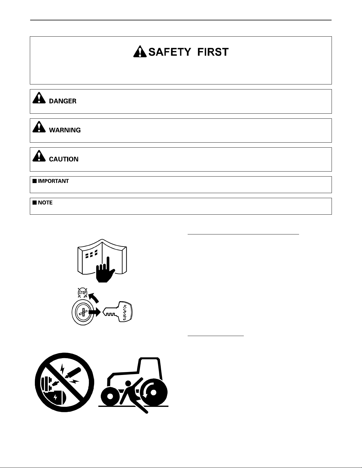
This symbol, the indu stry's "Saf ety Alert Symbol " is used throu ghout this ma nual and on labe ls on the mach ine
itself to warn of the possibility of per sonal injur y. Read these inst ructions care fully.It is essen tial that you read the
instructions and safety regulations before you attempt to repair or use this unit.
A Indicates an imminently hazardous situation which, if not avoided, will result in death or serious injury.
A Indicates a potentially hazardous situation which, if not avoided, could result in death or serious injury.
A Indicates a potentially hazardous situation which, if not avoided, may result in minor or moderate injury.
A Indicates that equipment or property damage could result if instructions are not followed.
A Gives helpful information.
BEFORE SERVICING AND REPAIRING
A Read all instruc tions and safety instructions in this
manual and on your machine safety decal s .
A Clean the work area and machine.
A Park the machine on a firm and level ground, and set
the parking brake.
A Lower the implement to the ground.
A Stop the engine, and remove the key
A Disconnect the battery negative cable
A Hang a "DO NOT OPERATE" tag in operator
station.
SAFETY STARTING
A Do not start the engine by shorting across starter
terminals or bypassing the safety start switch.
A Do not alter or remove any part of machine safety
system.
A Before starting the engine, make sure that all s hift
levers are in neutral positions or in disengaged
positions.
A Never start the engine while standing on ground.
Start the engine only from operator's seat.
0000000752E
0000000753E
0000000754E
1
GZD15, WSM SAFETY INSTRUCTIONS
KiSC issued 04, 2006 A
SAFETY WORKING
A Do not work on the machine while under the
influence of alcohol, medication, or other substances
or while fatigued.
A Wear close fitting clothing and safety equipment
appropriate to the job.
A Use tools appropriate to the wo rk. Makeshift tools,
parts, and procedures are not recommended.
A When servicing is performed together by two or
more persons, take care to perform all work safely.
A Do not work under the machine that is supported
solely by a jack. Always support the machine by
safety stands.
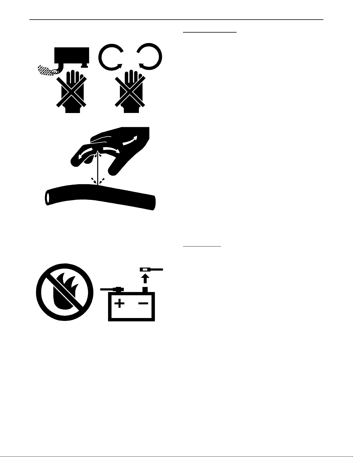
A Do not touch the rotating or hot parts while the
engine is running.
A Never remove the radiator cap while the e ngine is
running, or immediately after stopping. Otherwise,
hot water will spout out from radiator. Only remove
radiator cap when cool enough to touch with bare
hands. Slowly loos en the cap to fi rst stop to re lieve
pressure be fore removin g completely.
A Escaping fluid (fue l or hydraulic oil ) under pressure
can penetrate the skin causing serious injury.
Relieve pressure before disconnect ing hydraulic or
fuel lines. Tighten all connections before applying
pressure.
0000000755E
AVOID FIRES
A Fuel is extremely flammable and explosive under
certain condit ions. Do not smoke or al low fla mes or
sparks in your working area.
A To avoid sparks from an accidental short circuit,
always disconnect the battery negative cable first
and connect it last.
A Battery gas can explode. Keep sparks and open
flame away from the top of bat tery, esp ecially when
charging the battery.
A Make sure that no fuel has been spilled on the
engine.
0000000756E
2
GZD15, WSM SAFETY INSTRUCTIONS
KiSC issued 04, 2006 A
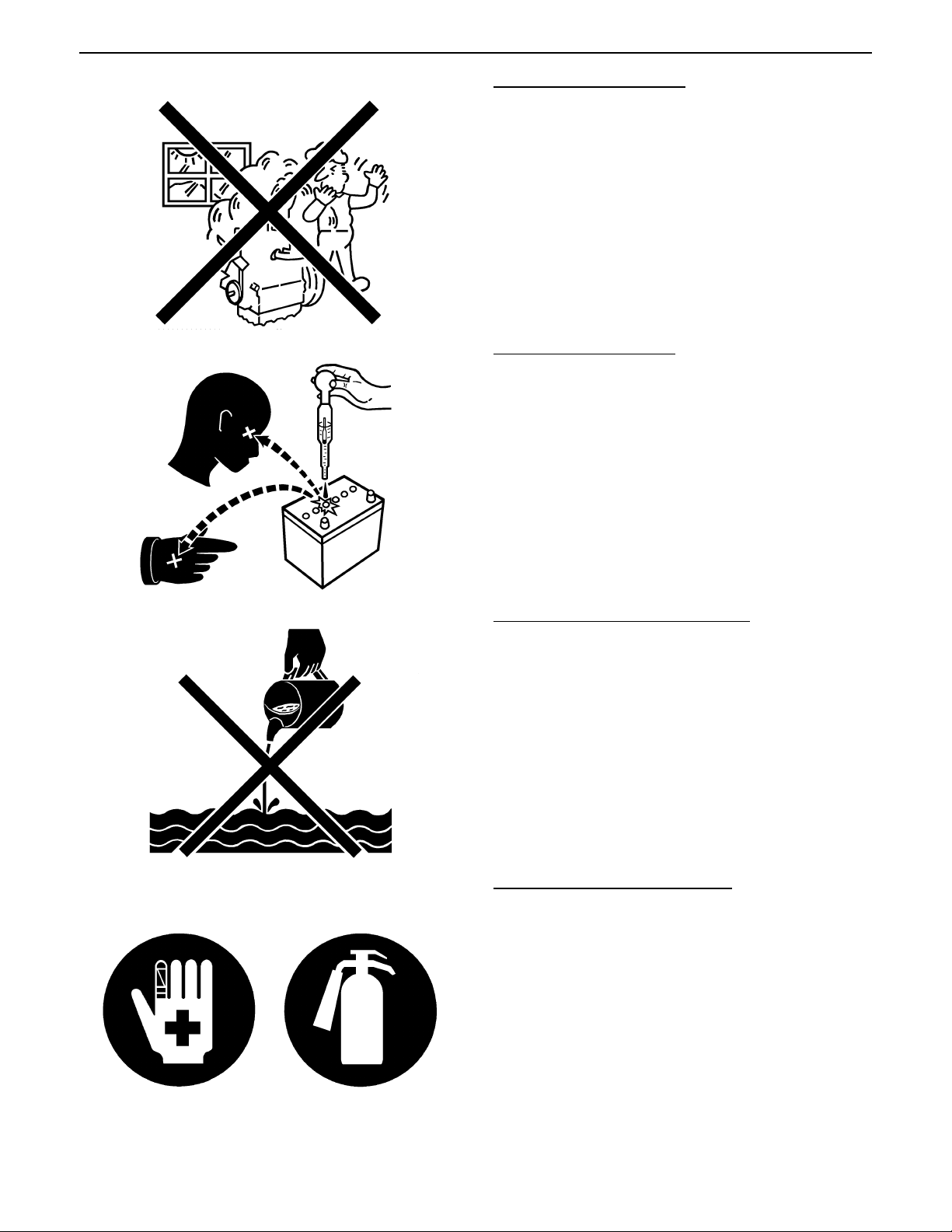
VENTILATE WORK AREA
A If the engine must be running to do some work, make
sure the area is well ventilated. Never run the engine
in a closed area. The exhaust gas contains
poisonous carbon monoxide.
0000000757E
PREVENT ACID BURNS
A Sulfuric acid in battery elec trolyte is poiso nous. It is
strong enough to burn skin, clothing and cause
blindness if splashed into eyes. Keep electrolyte
away from eyes, hands and clothing. If you spill
electrolyte on yourself, flush with water, and get
medical attention immediately.
0000000758E
DISPOSE OF FLUIDS PROPERLY
A Do not pour fluids in to the ground, down a drain, or
into a stream, pond, or lake. Observe relevant
environmental protection regulations when
disposing of oil, fuel, cool ant, electrolyte and other
harmful waste.
0000000759E
PREPARE FOR EMERGENCIES
A Keep a first aid k it and fire ex tingu isher h andy at all
times.
A Keep emergency numbers for doctors, ambulance
service, hospital and fire department near your
telephone.
0000000760E
3
GZD15, WSM SAFETY INSTRUCTIONS
KiSC issued 04, 2006 A
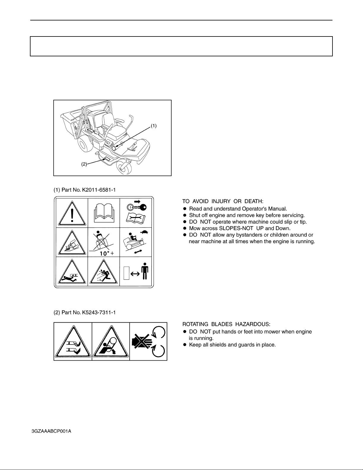
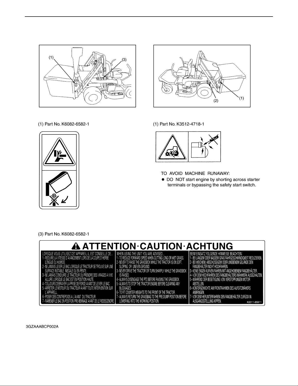
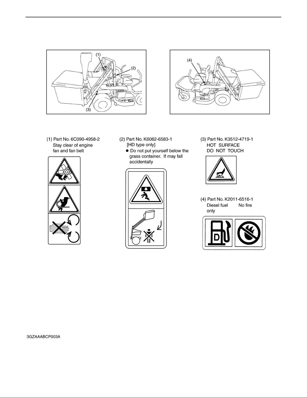
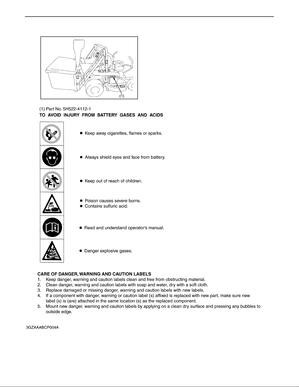
SAFETY DECALS
The following safety decals are installed on the machine. If a decal becomes damaged, illegible or is not
on the machine, replace it. The decal part number is listed in the parts list.
4
GZD15, WSM SAFETY INSTRUCTIONS
KiSC issued 04, 2006 A
5
GZD15, WSM SAFETY INSTRUCTIONS
KiSC issued 04, 2006 A
6
GZD15, WSM SAFETY INSTRUCTIONS
KiSC issued 04, 2006 A
0000001495E
7
GZD15, WSM SPECIFICATIONS
KiSC issued 04, 2006 A
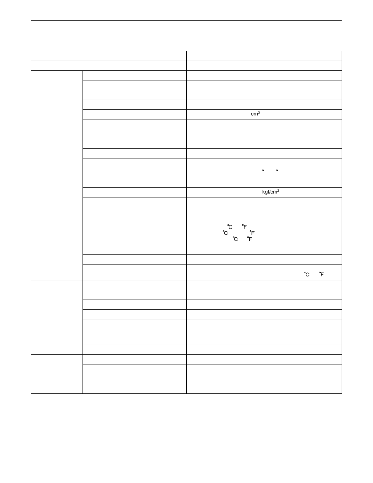
SPECIFICATIONS
Model GZD15-LD GZD15-HD
Maximum gross power 11.2 kW (15 HP) *1
Model Z602-GZD15
Type Indirect injection. Vertical, water-cooled, 4-cycle diesel engine
Number of cylinder 2
Bore and stroke 72.0 x 73.6 mm (2.83 x 2.90 in.)
Total displacement 599 (36.6 cu.in.)
Rated revolution 3000 rpm
Combustion chamber Spherical type (E-TVCS)
Fuel injection pump Bosh MD type mini pump
Governor Centrifugal ball mechanical governor
Injection nozzle Bosh throttle type
Engine
Capacities
Tyres
Traveling speeds
Injection timing 0.30 to 0.33 rad. (17 to 19 ) before T.D.C.
Injection order 1-2
Injection pressure 13.73 MPa (140 , 1990 psi)
Lubricating system Forced lubrication by gear pump
Cooling system Pressurized radiator, forced circulation with water pump
API Service c lassification C D , C E o r C F,
Lubricating oil
Starting system Electrical starter (12 V, 1.1 kW)
Battery 65D23L (12V, 52A.H. at 5H.R.)
Fuel
Fuel tank 20 L (5.3 U.S.gals, 4.4 lmp.gals)
Engine crankcase 2.1 L (2.2 U.S.qts, 1.8 lmp.qts)
Engine coolant 1.4 L (1.5 U.S.qts, 1.2 lmp.qts)
Recovery tank 0.25 L (0.26 U.S.qts., 0.22 Imp.qts.)
Transmission case & rear axle gear case (RH
& LH)
Front PTO case 0.13 L (0.14 U.S.gals, 0.11 lmp.gals)
Mower gear case oil 0.15 L (0.16 U.S.qts, 0.13 lmp.qts)
Front 15 x 6.0 - 6 (4 PR) Rib
Rear 20 x 10.0 - 12 (4 PR) Turf
Forward 0 to 13.5 km/h (0 to 8.4 mph)
Reverse 0 to 10.0 km/h (0 to 6.3 mph)
below 0 (32 ) : SAE 10W, 10W-30 or 10W-40,
0 to 25 (32 to 77 ) : SAE 20, 10W-30 or 10W-40,
above 25 (77 ) :SAE 30, 10W-30 or 10W-40
No.2-D Diesel fuel (ASTM D975)
[No. 1-D diesel fuel, if temperature is below -10 (14 )]
10.0 L (10.6 U.S.qts., 8.8 Imp.qts.)
NOTE:
*1 Manufacture's estimate
0000001496E
8

GZD15, WSM SPECIFICATIONS
KiSC issued 04, 2006 A
Model GZD15-LD GZD15-HD
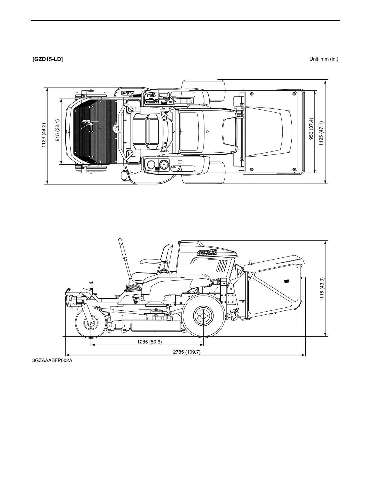
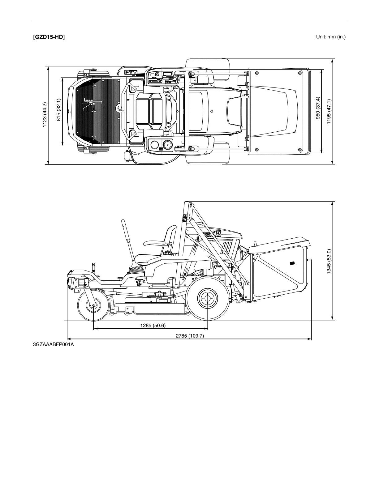
Overall length (with grass collector) 2785 mm (109.7 in.)
Overall width (with mower) 1195 mm (47.1 in.)
Dimensions
Weight (with mower deck and grass collector))
Overall height (without ROPS) 1115 mm (43.9 in.) 1345 mm (53.0 in.)
Wheel base 1285 mm (50.6 in.)
Tread
Front 815 mm (32.1 in.)
Rear 950 mm (37.4 in.), 850 mm (32.7 in.)
510 kg (1124.6 lbs) / with 40 in.
mower deck
540 kg (1190.7 lbs) / with 40 in.
mower deck
0000001497E
9
GZD15, WSM DIMENSIONS
KiSC issued 04, 2006 A
DIMENSIONS
10
GZD15, WSM DIMENSIONS
KiSC issued 04, 2006 A
0000001694E
11

KiSC issued 04, 2006 A
G GENERAL

CONTENTS
KiSC issued 04, 2006 A
1. IDENTIFICATION................................................................................................................G-1
2. GENERAL PRECAUTIONS................................................................................................G-2
3. HANDLING PRECAUTIONS FOR ELECTRICAL PARTS AND WIRING......................G-3
[1] WIRING..............................................................................................................................G-3
[2] BATTERY ..........................................................................................................................G-5
[3] FUSE .................................................................................................................................G-5
[4] CONNECTOR....................................................................................................................G-5
[5] HANDLING OF CIRCUIT TESTER....................................................................................G-6
4. LUBRICANTS, FUEL AND COOLANT.............................................................................G-7
5. TIGHTENING TORQUES...................................................................................................G-9
[1] GENERAL USE SCREWS, BOLTS AND NUTS ..........................................................G-9
[2] METRIC SCREWS, BOLTS AND NUTS....................................................................... G-9
[3] AMERICAN STANDARD SCREWS, BOLTS AND NUTS WITH
UNC OR UNF THREADS.............................................................................................G-10
[4] PLUGS.............................................................................................................................G-10
6. MAINTENANCE.................................................................................................................G-11
7. CHECK AND MAINTENANCE ........................................................................................G-13
[1] DAILY CHECK........................ .... ................................. ................................. .... ..............G-13
[2] CHECK POINTS OF INITIAL 50 HOURS...................................................................G-19
[3] CHECK POINT OF INITIAL 100 HOURS ...................................................................G-24
[4] CHECK POINTS OF EVERY 50 HOURS...................................................................G-25
[5] CHECK POINTS OF EVERY 100 HOURS.................................................................G-30
[6] CHECK POINT OF EVERY 150 HOURS ...................................................................G-34
[7] CHECK POINTS OF EVERY 200 HOURS.................................................................G-34
[8] CHECK POINTS OF EVERY 400 HOURS.................................................................G-36
[9] CHECK POINTS OF EVERY 1 YEAR........................................................................G-36
[10] CHECK POINTS OF EVERY 2 YEARS......................................................................G-39
[11] OTHERS..........................................................................................................................G-40
8. SPECIAL TOOLS .............................................................................................................G-50
[1] SPECIAL TOOLS FOR ENGINE.....................................................................................G-50
[2] SPECIAL TOOLS FOR MACHINE ...............................................................................G-56
GZD15, WSM GENERAL
KiSC issued 04, 2006 A
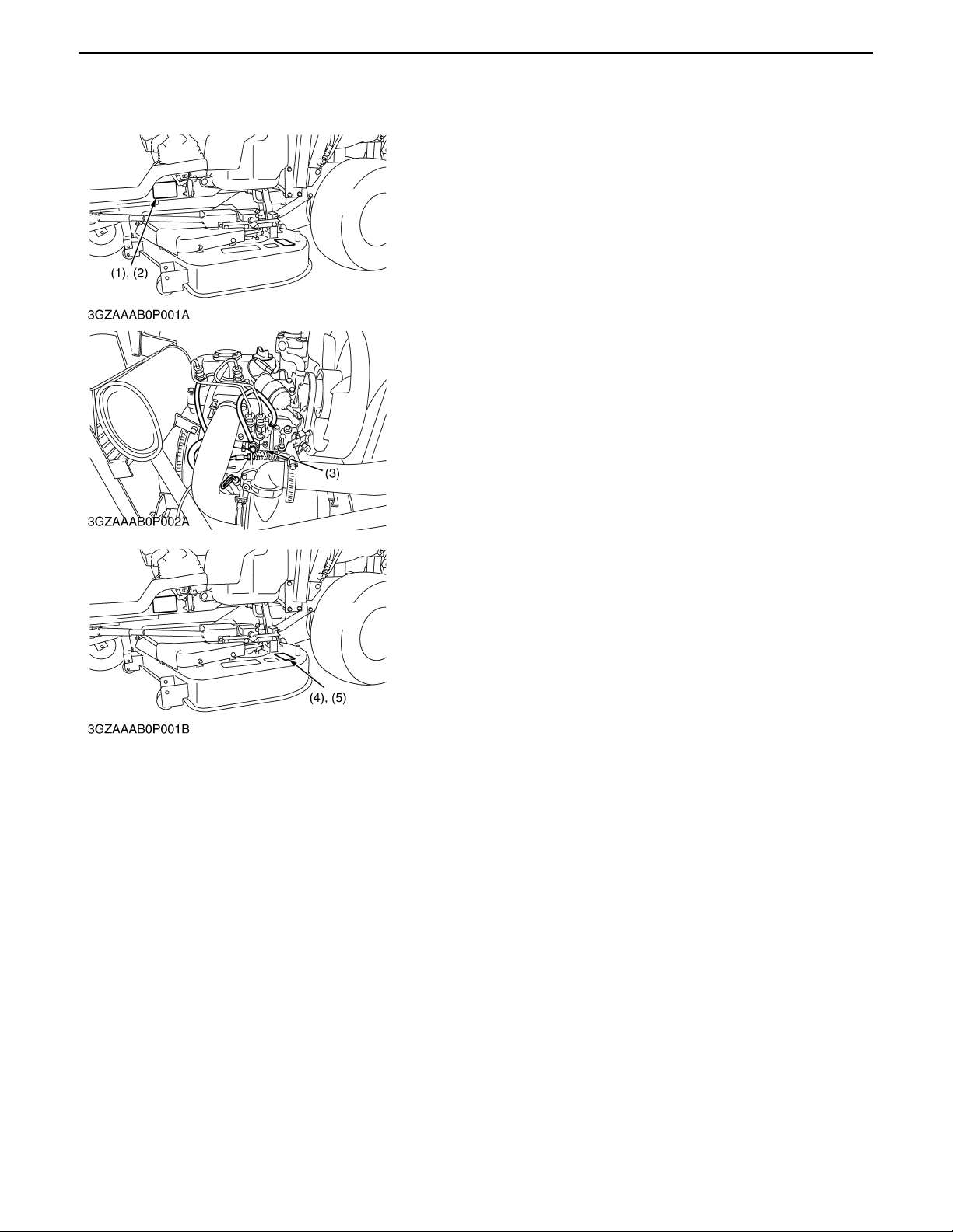
1. IDENTIFICATION
When contacting your local KUBOTA distributor, always specify
engine serial number (3), machine serial number (2), mower serial
number (4) and hour meter reading.
(1) Machine Identification Plate (4) Mower Serial Number
(2) Machine Serial Number (5) Mower Identification Plate
(3) Engine Serial Number
0000001409E
G-1
GZD15, WSM GENERAL
KiSC issued 04, 2006 A
2. GENERAL PRECAUTIONS
A During disassembly, carefully arrange removed parts in a
clean area to prevent conf usion late r. Screws, bolts and nuts
should be installed in their original position to prevent
reassembly errors.
A When special tools are required, use KUBOTA genuine
special tools. Special tools which are not frequently used
should be made according to the drawings provided.
A Before disassembling or servicing electrical wires, always
disconnect the ground cable from the battery first.
A Remove oil and dirt from parts before measuring.
A Use only KUBOTA genuine parts for parts replacement to
maintain machine performance and to assure safety.
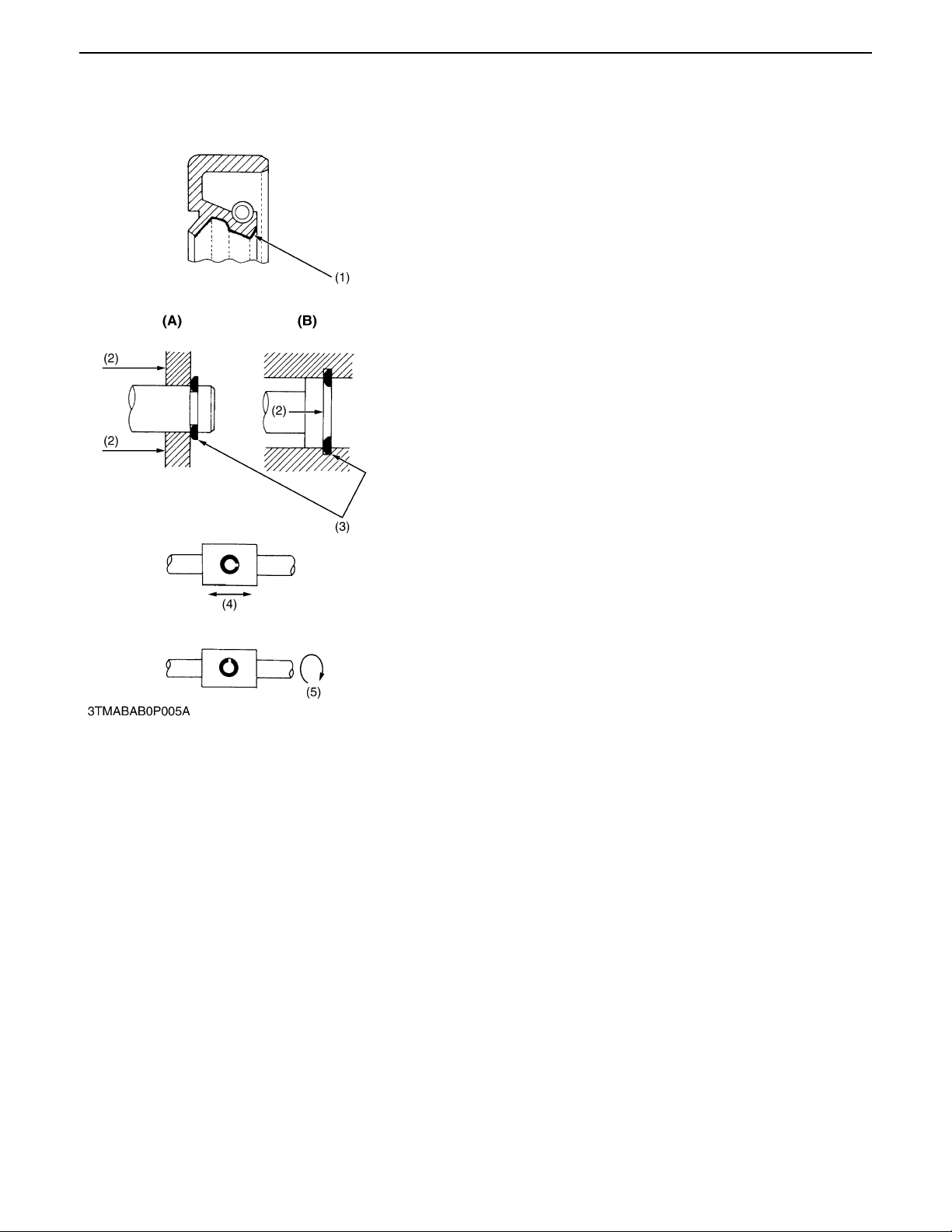
A Gaskets and O-rings must be replaced during reassembly.
Apply grease to new O -rings or oil seals b efore assembling.
See the figure left side.
A When reassembling external snap rings or internal snap rings,
they must be position ed so that sharp edge face s again st the
direction from which a force is applied. See the figure left side.
A When inserting spring pins, their splits must face the direction
from which a force is applied. See the figure left side.
A To prevent damage to t he hydraul ic system, u se only sp ecified
fluid or equivalent.
(1) Grease (A) External Snap Ring
(2) Force (B) Internal Snap Ring
(3) Sharp Edge
(4) Axial Force
(5) Rotating Movement
0000000612E
G-2
GZD15, WSM GENERAL
KiSC issued 04, 2006 A
3. HANDLING PRECAUTIONS FOR ELECTRICAL PARTS
AND WIRING
To ensure safety and prevent damage to the machine and
surrounding equipment, heed the following precautions in
handling electrical parts and wiring.
A Check electrical wiring for damage and loosened
connection every year. To this end, educate the customer
to do his or her own check and at the same time
recommend the dealer to perform periodic check for a fee.
A Do not attempt to modify or remodel any electrical parts
and wiring.
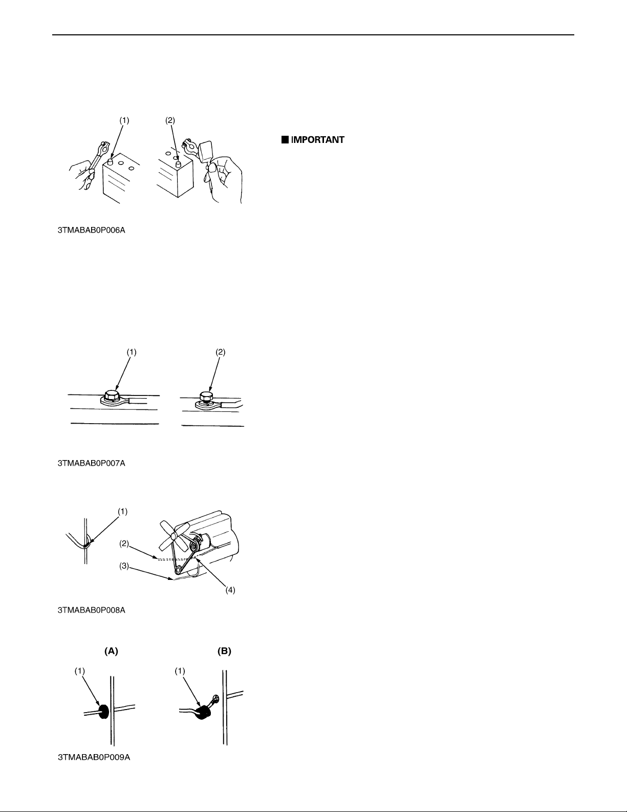
A When removing the battery cables, disconnect the
negative cable first. When installing the battery cables,
connect the positive cable first.
(1) Negative Terminal (2) Positive Terminal
0000000613E
[1] WIRING
A Securely tighten wiring terminals.
(1) Correct (2) Incorrect
(Securely Tighten) (Loosening Leads to Faulty
Contact)
A Do not let wiring contact dangerous part.
(1) Dangerous Part (3) Wiring (Correct)
(2) Wiring (Incorrect) (4) Dangerous Part
A Securely insert grommet.
(1) Grommet (A) Correct
(B) Incorrect
0000000614E
0000000615E
0000000616E
G-3
GZD15, WSM GENERAL
KiSC issued 04, 2006 A
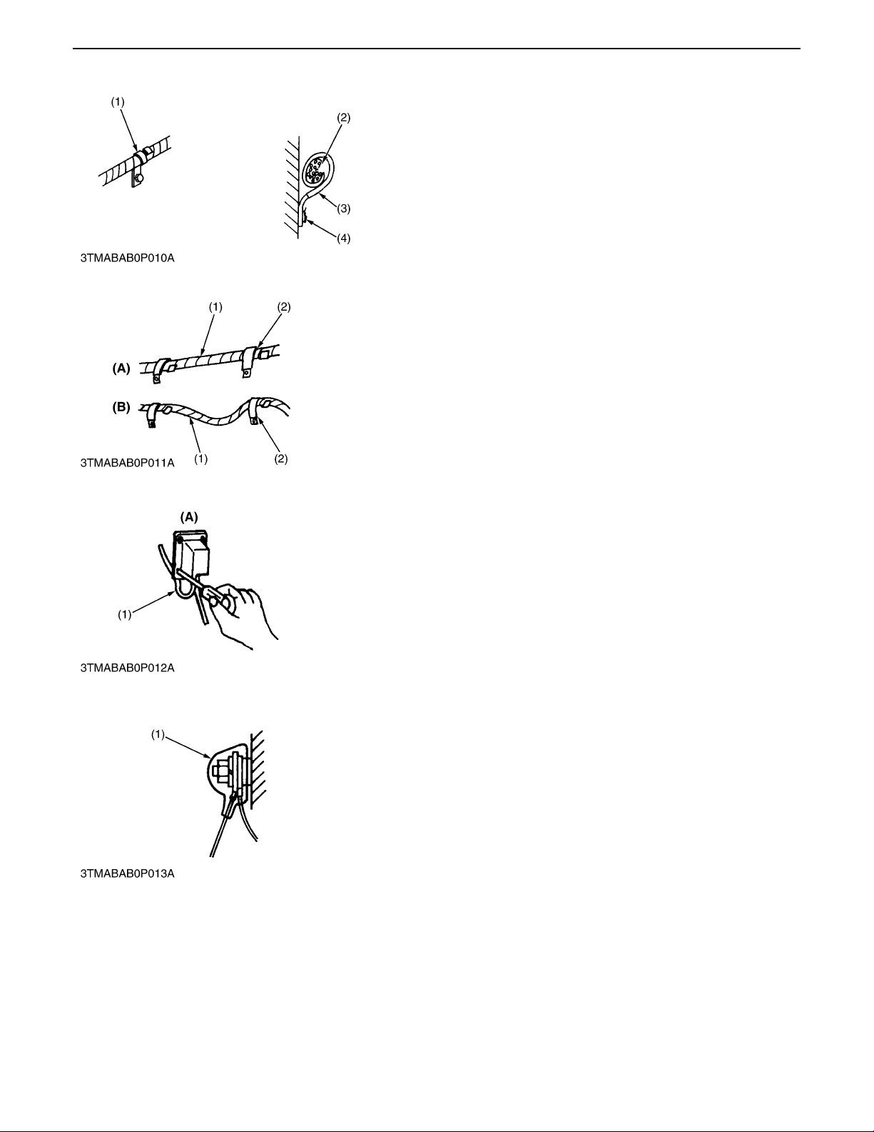
A Securely clamp, being careful not to damage wiring.
(1) Clamp (3) Clamp
*Wind Clamp Spirally (4) Welding Dent
(2) Wire Harness
0000000617E
A Clamp wiring so that there is no twist, unnecessary sag, or
excessive tension, except for movable part, where sag be
required.
(1) Wiring (A) Correct
(2) Clamp (B) Incorrect
0000000618E
A In installing a part, take care not to get wiring caught by it.
(1) Wiring (A) Incorrect
0000000619E
A After installing wiring, check protection of terminals and
clamped condition of wiring, only connect battery.
(1) Cover
*Securely Install Cover
0000000620E
G-4
GZD15, WSM GENERAL
KiSC issued 04, 2006 A
[2] BATTERY
A Take care not to confuse positive and negative terminal posts.
A When removing battery cables, disconnect negative cable
first. When installing battery cables, check for polarity and
connect positive cable first.
A Do not install an y b atte ry wi th ca pac it y o the r than is s pe ci fie d
(Ah).
A After connecting cab les to battery terminal posts, apply high
temperature grease to them and securely install terminal
covers on them.
A Do not allow dirt and dust to collect on battery.
A Take care not to let battery liquid spill on your skin and
clothes. If contaminated, wash it off with water
immediately.
A Before recharging the battery, remove it from the
machine.
A Before recharging, remove cell caps.
A Do recharging in a well-ventilated place where there is no
open flame nearby, as hydrogen gas and oxygen are
formed.
[3] FUSE
[4] CONNECTOR
0000000621E
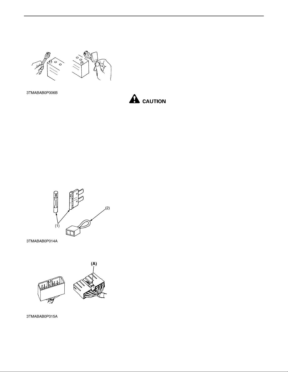
A Use fuses with specified capacity.
Neither too large or small capacity fuse is acceptable.
A Never use steel or copper wire in place of fuse.
A Do not install working light, radio set, etc. on machine which is
not provided with reserve powe r suppl y.
A Do not install accessories if fuse capacity of reserve power
supply is exceeded.
(1) Fuse (2) Fusible Link
0000000622E
A For connector with lock, push lock to separate.
(A) Push
0000000623E
G-5
GZD15, WSM GENERAL
KiSC issued 04, 2006 A
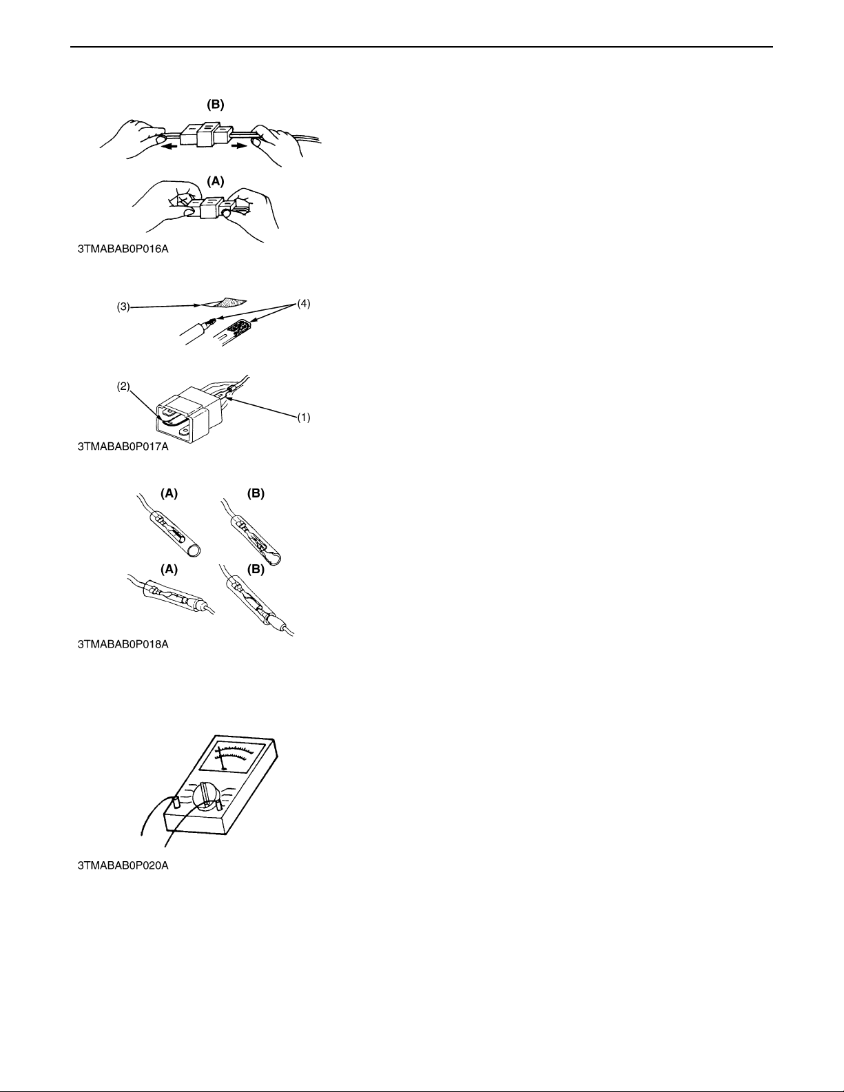
A In separating connectors, do not pull wire harnesses.
A Hold connector bodies to separate.
(A) Correct (B) Incorrect
0000000624E
A Use sandpaper to remove rust from terminals.
A Repair deformed termin al. Make certain th ere is no terminal
being exposed or displaced.
(1) Exposed Terminal (3) Sandpaper
(2) Deformed Terminal (4) Rust
0000000625E
A Make certain that there is no female connector being too open.
(A) Correct (B) Incorrect
[5] HANDLING OF CIRCUIT TESTER
A Use tester correctly following manual provided with tester.
A Check for polarity and range.
0000000626E
0000000628E
G-6
GZD15, WSM GENERAL
KiSC issued 04, 2006 A
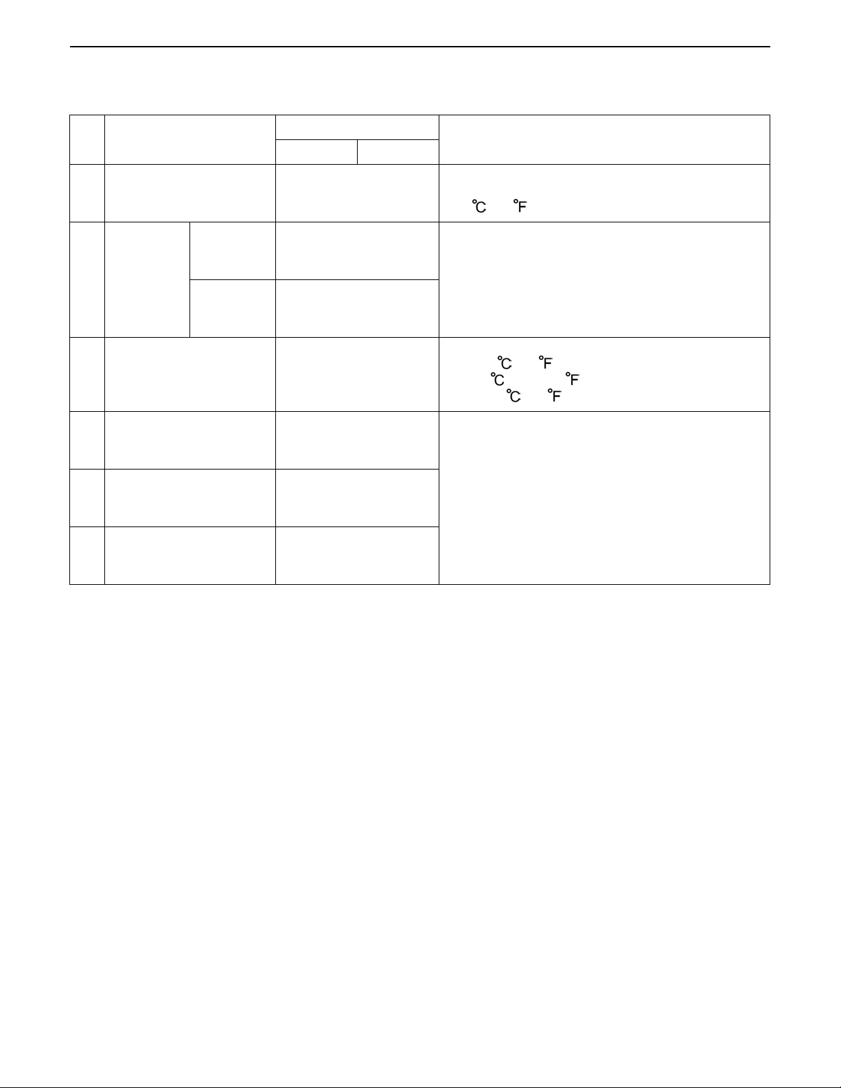
4. LUBRICANTS, FUEL AND COOLANT
No. Place
1 Fuel tank
Cooling
system
2Coolant
Recovery
tank
3 Engine crankcase
Transmission case and
4
rear axle gear case
(RH and LH)
Capacity
GZD15-LD GZD15-HD
20 L
5.3 U.S.gals.
4.4 lmp.gals.
1.4 L
1.5 U.S.qts.
1.2 lmp.qts.
0.25 L
0.26 U.S.qts.
0.22 lmp.qts.
2.1 L
2.2 U.S.qts.
1.8 lmp.qts.
10.0 L
2.6 U.S.gals.
2.2 lmp.gals.
0.15 L
0.16 U.S.qts.
0.13 Imp.qts.
Lubricants, fuel and coolant
No. 2-D diesel fuel
No. 1-D diesel fuel if temperature is below
-10 (14 )
Fresh clean water with anti-freeze
Engine oil: API service classification CD, CE or CF
Below 0 (32 ) : SAE10W, 10W-30 or 10W-40
0 to 25 (32 to 77 ) : SAE20, 10W-30 or 10W-40
Above 25 (77 ) : SAE30, 10W-30 or 10W-40
KUBOTA UDT or SUPER UDT fluid**5 Mower gear box
0.13 L
6 Front PTO case
*Oil amount when the oil level is at the upper of the oil level gauge.
**KUBOTA original transmission hydraulic fluid.
0.14 U.S.qts.
0.11 Imp.qts.
0000001410E
G-7

GZD15, WSM GENERAL
KiSC issued 04, 2006 A
Greasing, oiling (Machine)
No. Place No. of greasing point Capacity Type of grease
7 Motion control lever boss 2
8 Centre pin 1
9King pin 2
10 Front wheel 2
11 Front PTO drive shaft 2
12 Engi ne uni ve rsal join t 1
13 Motion control lever
14 Seat adjus ter
15 Hydraulic lift pedal
16 Cable
17 Grass collector link
18 Universal joint 3
19 Two sp ind le sh afts 2
Until grease overflows
Moderate amount oil Oil
Greasing (Mower)
Until grease overflows
SAE multi-purpose type
grease
SAE multi-purpose type
grease
0000001411E
G-8
GZD15, WSM GENERAL
KiSC issued 04, 2006 A
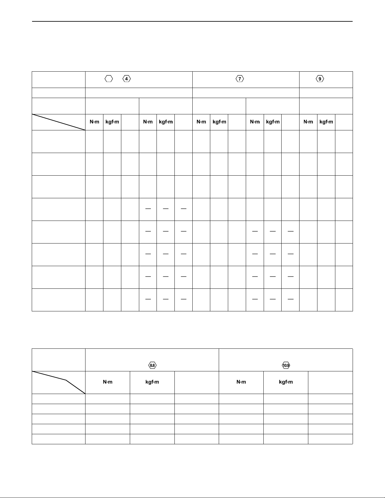
5. TIGHTENING TORQUES
[1] GENERAL USE SCREWS, BOLTS AND NUTS
Screws, bolt and n uts whose tightening torque are n ot specified in this Workshop M anual should be tightened
according to the table below.
Indication on top of
bolt
Material of bolt SS400, S20C S43C, S48C SCr435, SCM435
Material of
opponent part
Unit
Diameter
M6
(6 mm, 0.24 in.)
M8
(8 mm, 0.31 in.)
M10
(10 mm, 0.39 in.)
M12
(12 mm, 0.47 in.)
M14
(14 mm, 0.55 in.)
M16
(16 mm, 0.63 in.)
M18
(18 mm, 0.71 in.)
M20
(20 mm, 0.79 in.)
7.85
to
9.31
17.7
to
20.5
39.3
to
45.1
62.8
to
72.5
108
to
125
167
to
191
246
to
284
334
to
392
No-grade or 4T 7T 9T
Ordinariness Aluminum Ordinariness Aluminum Ordinariness
ft-lbs ft-lbs ft-lbs ft-lbs ft-lbs
0.80
5.79
7.85
0.80
5.79
9.81
1.00
7.24
7.85
0.80
5.79
12.3
to
0.95
1.8
to
2.1
4.0
to
4.6
6.4
to
7.4
11.0
to
12.8
17.0
to
19.5
25.0
to
29.0
34.0
to
40.0
to
6.87
13.1
to
15.1
29.0
to
33.2
46.3
to
53.5
79.6
to
92.5
123
to
141
181
to
209
246
to
289
to
8.82
16.7
to
19.6
31.4
to
34.3
to
0.90
1.7
to
2.0
3.2
to
3.5
to
6.50
12.3
to
14.4
23.2
to
25.3
to
11.2
23.6
to
27.4
48.1
to
55.8
77.5
to
90.2
124
to
147
197
to
225
275
to
318
368
to
431
to
1.15
2.4
to
2.8
4.9
to
5.7
7.9
to
9.2
12.6
to
15.0
20.0
to
23.0
28.0
to
32.5
37.5
to
44.0
to
8.31
17.4
to
20.2
35.5
to
41.2
57.2
to
66.5
91.2
to
108
145
to
166
203
to
235
272
to
318
to
8.82
17.7
to
20.5
39.3
to
44.1
62.8
to
72.5
to
0.90
1.8
to
2.1
4.0
to
4.5
6.4
to
7.4
to
6.50
13.1
to
15.1
29.0
to
32.5
46.3
to
53.5
to
14.2
29.5
to
34.3
60.9
to
70.6
103
to
117
167
to
196
260
to
304
344
to
402
491
to
568
1.25
to
1.45
3.0
to
3.5
6.2
to
7.2
10.5
to
12.0
17.0
to
20.0
26.5
to
31.0
35.0
to
41.0
50.0
to
58.0
9.05
to
10.4
21.7
to
25.3
44.9
to
52.0
76.0
to
86.7
123
to
144
192
to
224
254
to
296
362
to
419
[2] METRIC SCREWS, BOLTS AND NUTS
Unit
Nominal
Diameter
0000001412E
Grade
M8 23.6 to 27.4 2.4 to 2.8 17.4 to 20.2 29.4 to 34.3 3.0 to 3.5 21.7 to 25.3
M10 48.1 to 55.8 4.9 to 5.7 35.5 to 41.2 60.8 to 70.5 6.2 to 7.2 44.9 to 52.1
M12 77.5 to 90.1 7.9 to 9.2 57.2 to 66.5 103.0 to 117.0 10.5 to 12.0 76.0 to 86.8
M14 124.0 to 147.0 12.6 to 15.0 91.2 to 108.0 167.0 to 196.0 17.0 to 20.0 123.0 to 144.0
M16 196.0 to 225.0 20.0 to 23.0 145.0 to 166.0 260.0 to 303.0 26.5 to 31.0 192.0 to 224.0
Property class 8.8
ft-lbs ft-lbs
Property class 10.9
0000001413E
G-9
GZD15, WSM GENERAL
KiSC issued 04, 2006 A
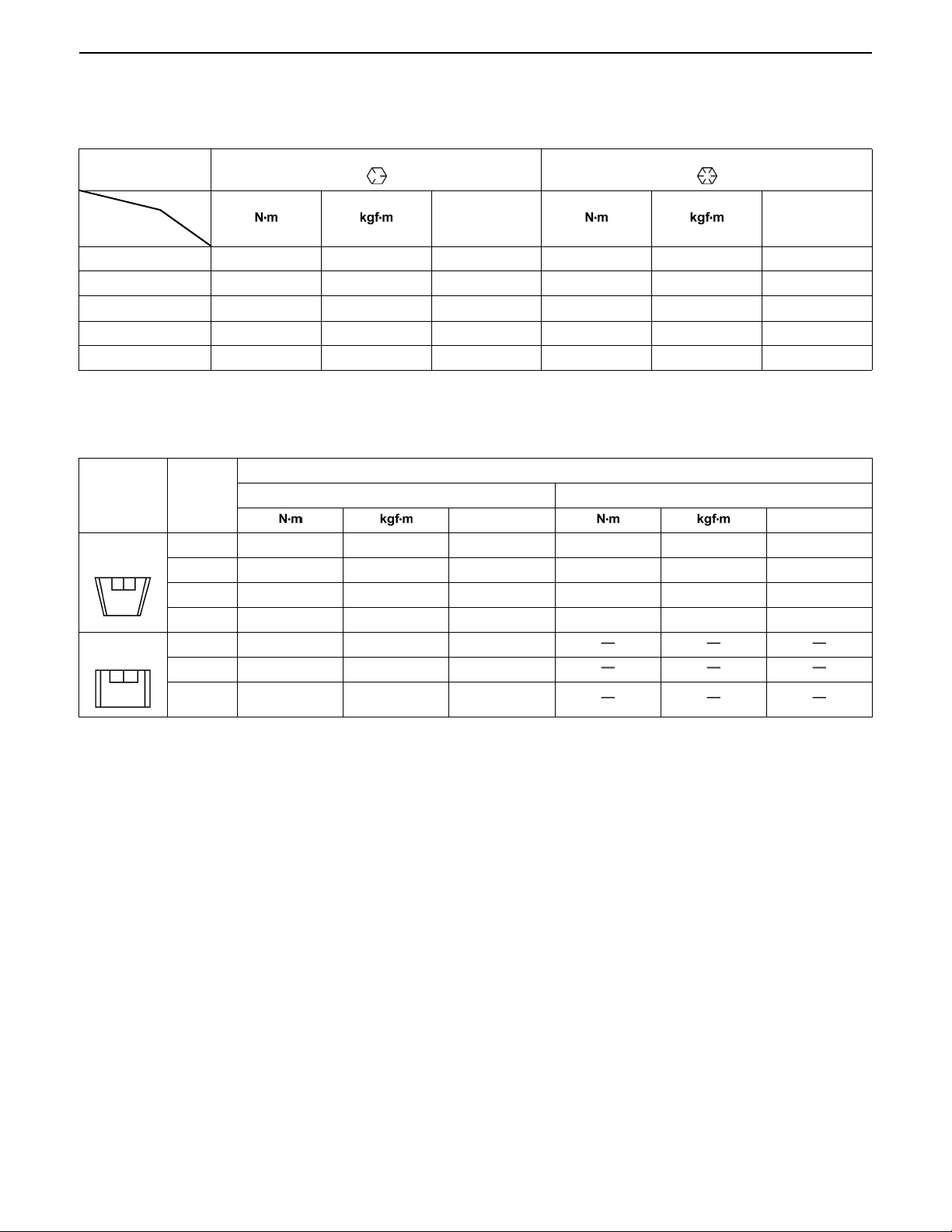
[3] AMERICAN STANDARD SCREWS, BOLTS AND NUTS WITH UNC OR
UNF THREADS
Grade
Unit
Norminal
Diameter
5/16 23.1 to 27.8 2.35 to 2.84 17.0 to 20.5 32.5 to 39.3 3.31 to 4.01 24.0 to 29.0
3/8 47.5 to 57.0 4.84 to 5.82 35.0 to 42.0 61.0 to 73.2 6.22 to 7.47 45.0 to 54.0
1/2 108.5 to 130.2 11.07 to 13.29 80.0 to 96.0 149.2 to 179.0 15.22 to 18.27 110.0 to 132.0
9/16 149.2 to 179.0 15.22 to 18.27 110.0 to 132.0 217.0 to 260.4 22.14 to 26.57 160.0 to 192.0
5/8 203.4 to 244.1 20.75 to 24.91 150.0 to 180.0 298.3 to 358.0 30.44 to 36.53 220.0 to 264.0
[4] PLUGS
Shape Size
Tapered
screw
Straight
screw
SAE GR.5 SAE GR.8
ft-lbs ft-lbs
0000001414E
Material of opponent part
Ordinariness Aluminum
ft-lbs ft-lbs
R1/8 12.7 to 21.6 1.3 to 2.2 9.4 to 15.9 12.7 to 19.6 1.3 to 2.0 9.4 to 15.4
R1/4 24.5 to 44.1 2.5 to 4.5 18.1 to 32.5 24.5 to 34.3 2.5 to 3.5 18.1 to 25.4
R3/8 49.0 to 88.3 5.0 to 9.0 36.2 to 65.1 49.0 to 58.8 5.0 to 6.0 36.2 to 43.4
R1/2 58.8 to 107.9 6.0 to 11.0 43.4 to 79.6 58.8 to 78.5 6.0 to 8.0 43.4 to 57.9
G1/4 24.5 to 34.3 2.5 to 3.5 18.1 to 25.3
G3/8 61.8 to 82.4 6.3 to 8.4 45.6 to 60.8
G1/2 49.0 to 88.3 5.0 to 9.0 36.2 to 65.1
0000001666E
G-10

GZD15, WSM GENERAL
KiSC issued 04, 2006 A
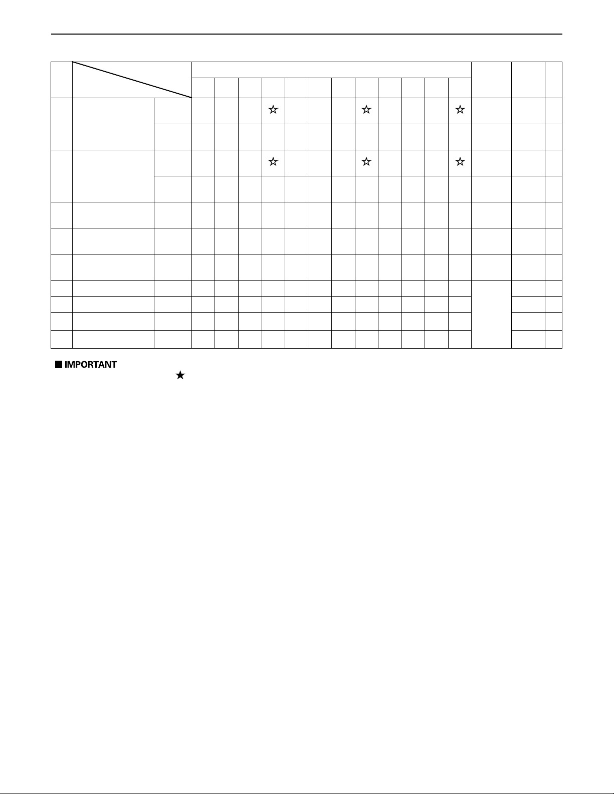
6. MAINTENANCE
Period
No.
Item
1 Engine oil Change
2 Engine oil filter Replace
Transmission and
3
Rear axle gear case
(RH and LH) fluid
Transmission oil
4
filter
Transmission
5
strainer
6 Front PTO case fluid
7 Front axle pivot Adjust
8 Safety device Check
9 Oiling -
Greasing
10
(without mower)
11 Mower gear box oil
12 Air cleaner element
13 Battery condition Check
14 Fan belt Adjust
15 Parking brake Adjust
16 Fuel filter element
17 Fuel line
Change
Replace
Clean
Check
Change
Check
Change
Clean
Replace
Check
Replace
Check
Replace
Indication on hour meter
50 100 150 200 250 300 350 400 450 500 550 600
-
After
since
every
100Hr
every
200Hr
every
200Hr
every
200Hr
every
200Hr
every
50Hr
every
150Hr
every
200Hr
every
50Hr
every
50Hr
every
50Hr
every
50Hr
every
150Hr
every
50Hr
every
1 year
every
50Hr
every
100Hr
every
100Hr
every
100Hr
every
400Hr
every
100Hr
every
2 years
Refer-
ence
page
G-19
G-20
G-21
G-20
G-23
G-29
G-29
G-24 *2
G-25
G-28
G-27
G-26
G-34
G-26 *1
G-36
G-32
G-31
G-31 *2
G-30
G-36 *2
G-30
G-39 *2
0000001415E
G-11
GZD15, WSM GENERAL
KiSC issued 04, 2006 A
Period
No.
Item
Radiator hose and
18
clamp
19 Hydraulic hose
20 Radiator Clean
21 Coolant Change
22 Mower gear box seal Replace
23 Fuel system Bleed
24 Fuse Replace G-40
25 Blade Replace G-41
26 Mower belt Replace G-42
Check
Replace
Check
Replace
50 100 150 200 250 300 350 400 450 500 550 600
Indication on hour meter
After
since
every
200Hr
every
2 years
every
200Hr
every
2 years
every
1 year
every
1 year
every
2 years
Service
as
required
Refer-
ence
page
G-35
G-39 *2
G-35
G-39 *2
G-37
G-37
G-39 *2
G-42
A The jobs indicated by must be done initially.
A *1: This maintenance should be done daily more often in dusty condition than in normal conditions.
Suggested cleaning interval is every 100 hours in normal conditions.
A *2: These items should be serviced by an authorized KUBOTA Distributor, unless the owner has the
proper tools and is mechanically proficient.
0000001416E
G-12

GZD15, WSM GENERAL
KiSC issued 04, 2006 A
7. CHECK AND MAINTENANCE
A Be sure to check and service the machine on a flat place with engine shut off, the parking brake on and
chock the wheels.
0000001417E
[1] DAILY CHECK
To prevent trouble from occurring, it is important to know the condition of the machine. Check the following items
before starting.
Checking
A Check areas where previous trouble was experienced.
A Walk around the machine.
1. Tire pressure, wear and damage
2. Oil and water leak
3. Engine oil level
4. Transmission fluid level
5. Coolant level in the recovery tank
6. Damage of machine body, tightness of all bolts and nuts
7. Radiator screen
8. Panel screen
9. Brake play
10.Air cleaner
11.Fuel level
12.Oiling
A Mower
1. Oil leak
2. Make sure blade cap screws are tight.
3. Check blades for wear or damage.
4. Check all hardware.
5. Make sure all pins are in place.
6. Mower deck cleaning
7. Greasing
A While sitting in the operator's seat,
1. Motion control lever
2. Parking brake
A Starting the engine,
1. Color of the exhaust fumes
2. Safety start switch, seat safety control and another safety control and another safety devices.
3. Check for abnormal noise and vibration.
0000001418E
G-13

GZD15, WSM GENERAL
KiSC issued 04, 2006 A
Checking Engine Oil Level
A Always stop the engine and remove the key before
checking oil.
1. Check engine oil before start ing and 5 m inutes or mo re after
the engine has stopped.
2. Wipe dipstick area clean.
3. To check the oil level, remove the dipstick, wipe it clean,
replace it, and draw it out again. Check to see that the oil level
is between the two notches.
4. Add new oil to the prescribed level at the oil port if necessary.
5. When using a different brand or viscosity oil from the previous
one, remove all of the old oil and oil filter. Never mix two
different types of oil.
6. Use the proper Engine Oil SAE according to the ambient
temperatures. (See page G-7.)
(1) Engine Oil Port (A) Upper Level
(2) Oil Level Dipstick (B ) Lower Level
0000001422E
G-14
GZD15, WSM GENERAL
KiSC issued 04, 2006 A
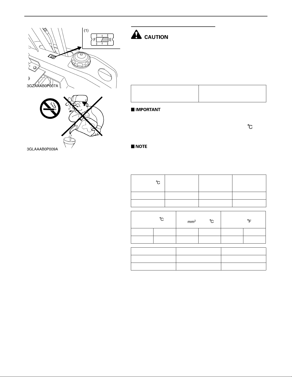
Checking Am ount of Fuel and Refueling
A Handle fuel carefully. If the engine is running, do not fill
the fuel tank. If engine is hot, let engine cool several
minutes before adding fuel.
Do not smoke while filling the fuel tank or servicing the
fuel system. Fill fuel tank only to bottom of filler neck.
Check the fuel level. Take care that the fuel tank does not
become empty.
Fuel tank capacity
20L
5.3 U.S.gals.
4.4 Imp.gals.
A Use Diesel Fuel Only.
1. Use No.2 diesel fuel.
2. Use No.1 diesel fuel if the temperature is below -10 .
3. Always use a strainer whe n refueling to prevent fu el injectio n
pump contamination.
A No.2-D is a distillate fuel of lower volatility for engines in
industrial and heavy mobile service.
(SAE J313 JUN87)
Grade of Diesel Fuel Oil according to ASTM D975
Water and
Flash point
Min Max Max Max
52 0.05 0.35 0.01
Distillation
Temperatures 90%
Point
MinMaxMinMaxMinMax
282 338 1.9 4.1 32.6 40.1
Sulfur, weight Copper strip Corrosion Cetane Number
Max Max Min
0.50 No.3 40
(1) Fuel Gauge E: Empty
Sediment,
volume %
Viscosity Kinematics cSt
or /S at 40
Carbon Residue
on, 10 percent
Residuum %
Viscosity Saybolt, SUS
F: Full
Ash, weight %
at 100
0000001667E
G-15
 Loading...