

Kubota GR1600EC2 Workshop Manual

WORKSHOP MANUAL
KiSC issued 07, 2006 A
GR1600EC2

TO THE READER
KiSC issued 07, 2006 A
This Workshop Manual has been prepared to provide servicing personnel with
information on the mechanism, service and maintenance of KUBOTA GR1600EC2. It is
divided into three parts, “General”, “Mechanism” and “Servicing”.
■ General
Information on the tractor identification, the general precautions, maintenance check
list, check and maintenance and special tools are described.
■ Mechanism
Information on the construction and function are included. This part should be
understood before proceeding with troubleshooting, disassembling and servicing.
■ Servicing
Information on the troubleshooting, servicing specification lists, tightening torque,
checking and adjusting, disassembling and assembling, and servicing which cover
procedures, precautions, factory specifications and allowable limits.
All information illustrations and specifications contained in this manual are based on
the latest product information available at the time of publication.
The right is reserved to make changes in all information at any time without notice.
Due to covering many models of this manual, information or picture being used, have
not been specified as one model.
© KUBOTA Corporation 2006
July 2006
GR1600EC2, WSM
SAFETY FIRST
KiSC issued 07, 2006 A
SAFETY INSTRUCTIONS
SAFETY INSTRUCTIONS
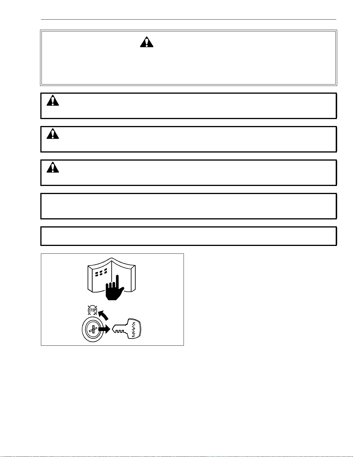
This symbol, the industry’s “Safety Alert Symbol”, is used throughout this manual and on labels on
the machine itself to warn of the possibility of personal injury. Read these instructions carefully.
It is essential that you read the instructions and safety regulations before you attempt to repair or use
this unit.
DANGER : Indicates an imminently hazardous situation which, if not avoided, will result in
death or serious injury.
WARNING : Indicates a potentially hazardous situation which, if not avoided, could result in
death or serious injury.
CAUTION : Indicates a potentially hazardous situation which, if not avoided, may result in
minor or moderate injury.
■ IMPORTANT : Indicates that equipment or property damage could result if instructions are not
followed.
■ NOTE : Gives helpful information.
BEFORE SERVICING AND REPAIRING
• Read all instructions and safety instructions in this
manual and on your machine safety decals.
• Clean the work area and machine.
• Park the machine on a firm and level ground, and set
the parking brake.
• Lower the implement to the ground.
• Stop the engine, and remove the key.
• Disconnect the battery negative cable.
• Hang a “DO NOT OPERATE” tag in operator
station.
1
GR1600EC2, WSM
KiSC issued 07, 2006 A
SAFETY INSTRUCTIONS
SAFETY STARTING
• Do not start the engine by shorting across starter
terminals or bypassing the safety start switch.
• Do not alter or remove any part of machine safety
system.
• Before starting the engine, make sure that all shift
levers are in neutral positions or in disengaged
positions.
• Never start the engine while standing on ground.
Start the engine only from operator’s seat.
SAFETY WORKING
• Do not work on the machine while under the influence
of alcohol, medication , or other substances or while
fatigued.
• Wear close fitting clothing and safety equipment
appropriate to the job.
• Use tools appropriate to the work. Makeshift tools,
parts, and procedures are not recommended.
• When servicing is performed together by two or more
persons, take care to perform all work safely.
• Do not work under the machine that is supported
solely by a jack. Always support the machine by
safety stands.
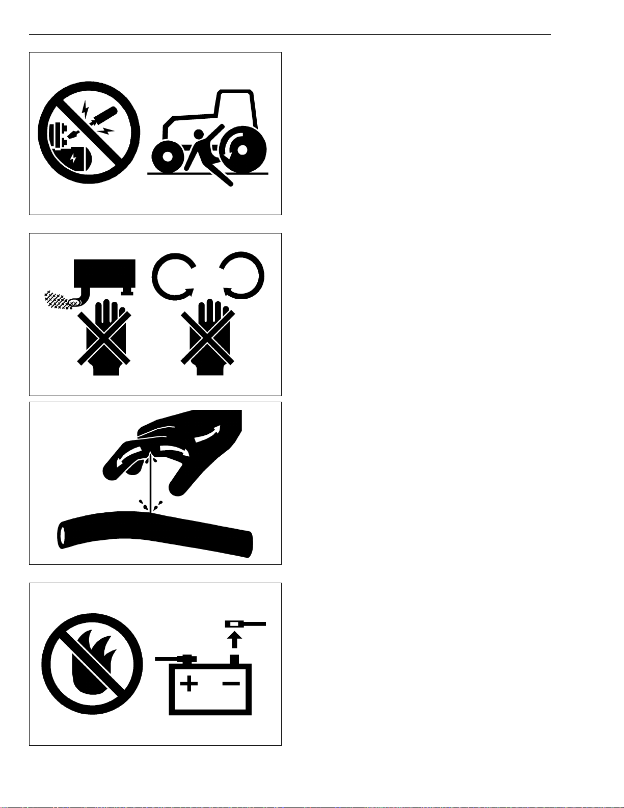
• Do not touch the rotating or hot parts while the engine
is running.
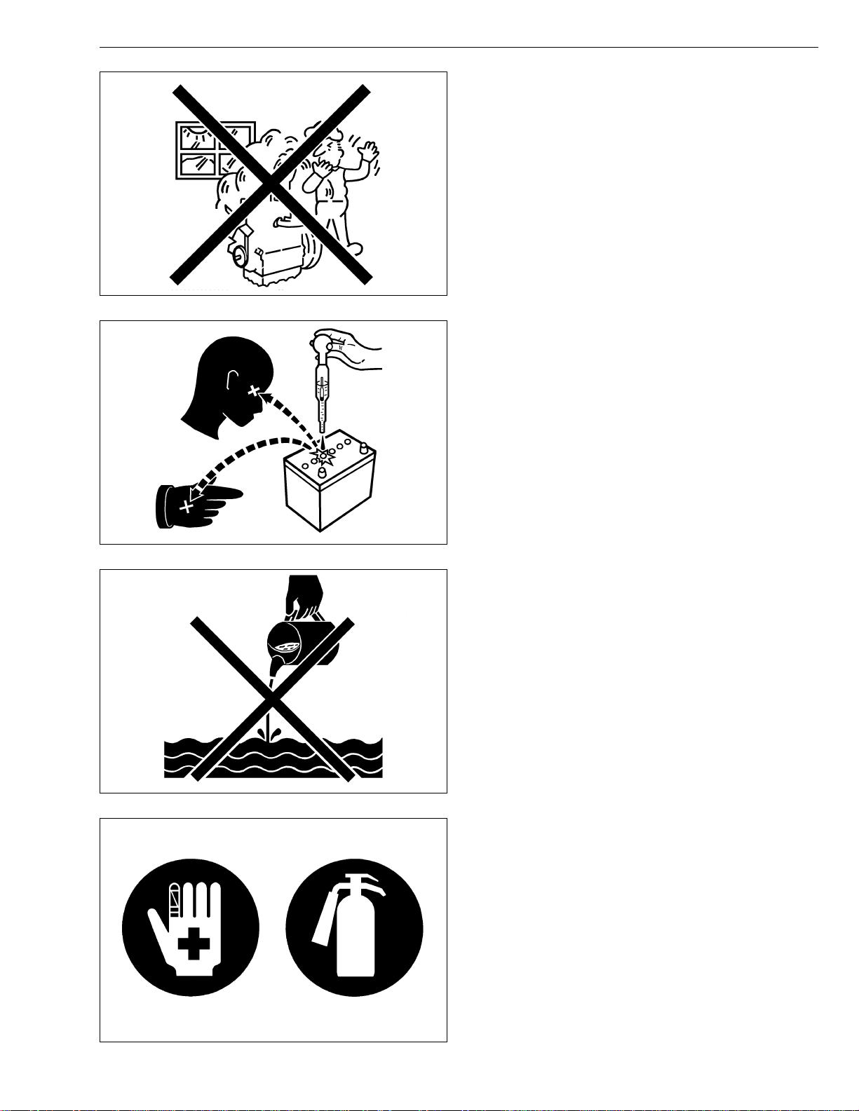
• Never remove the radiator cap while the engine is
running, or immediately after stopping. Otherwise, hot
water will spout out from radiator. Only remove
radiator cap when cool enough to touch with bare
hands. Slowly loosen the cap to first stop to relieve
pressure before removing completely.
• Escaping fluid (fuel or hydraulic oil) un der pressure
can penetrate the skin causing serious injury. Relieve
pressure before disconnecting hydraulic or fuel lines.
Tighten all connections before applying pressure.
AVOID FIRES
• Fuel is extremely flammable and explosive under
certain conditions. Do not smoke or allow flames or
sparks in your working area.
• To avoid sparks from an accidental short circuit,
always disconnect the battery negative cable first and
connect it last.
• Battery gas can explode. Keep sparks and open
flame away from the top of b attery, especially when
charging the battery.
• Make sure that no fuel has been spilled on the engine.
2
GR1600EC2, WSM
KiSC issued 07, 2006 A
SAFETY INSTRUCTIONS
VENTILATE WORK AREA
• If the engine must be running to do some work, make
sure the area is well ventilated . Neve r run the eng ine
in a closed area. The exhaust gas contains poisonous
carbon monoxide.
PREVENT ACID BURNS
• Sulfuric acid in batte ry electrolyte is poisonou s. It is
strong enough to burn skin, clothing and cause
blindness if splashed into eyes. Keep electrolyte
away from eyes, hands and clothing. If you spill
electrolyte on yourself, flush with water, and get
medical attention immediately.
DISPOSE OF FLUIDS PROPERLY
• Do not pour fluids into the ground, down a drain, or
into a stream, pond, or lake. Observe relevant
environmental prot ectio n regulati ons whe n disp osing
of oil, fuel, coolant, electrolyte and other harmful
waste.
PREPARE FOR EMERGENCIES
• Keep a first aid kit and fire extingui sher handy at all
times.
• Keep emergency numbers for doctors, ambulance
service, hospital and fire department near your
telephone.
3
GR1600EC2, WSM
KiSC issued 07, 2006 A
SAFETY INSTRUCTIONS
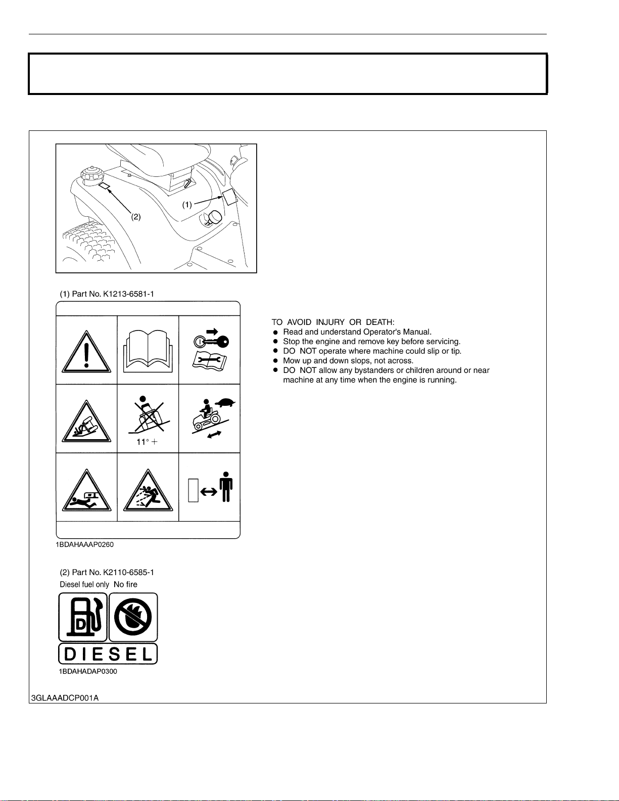
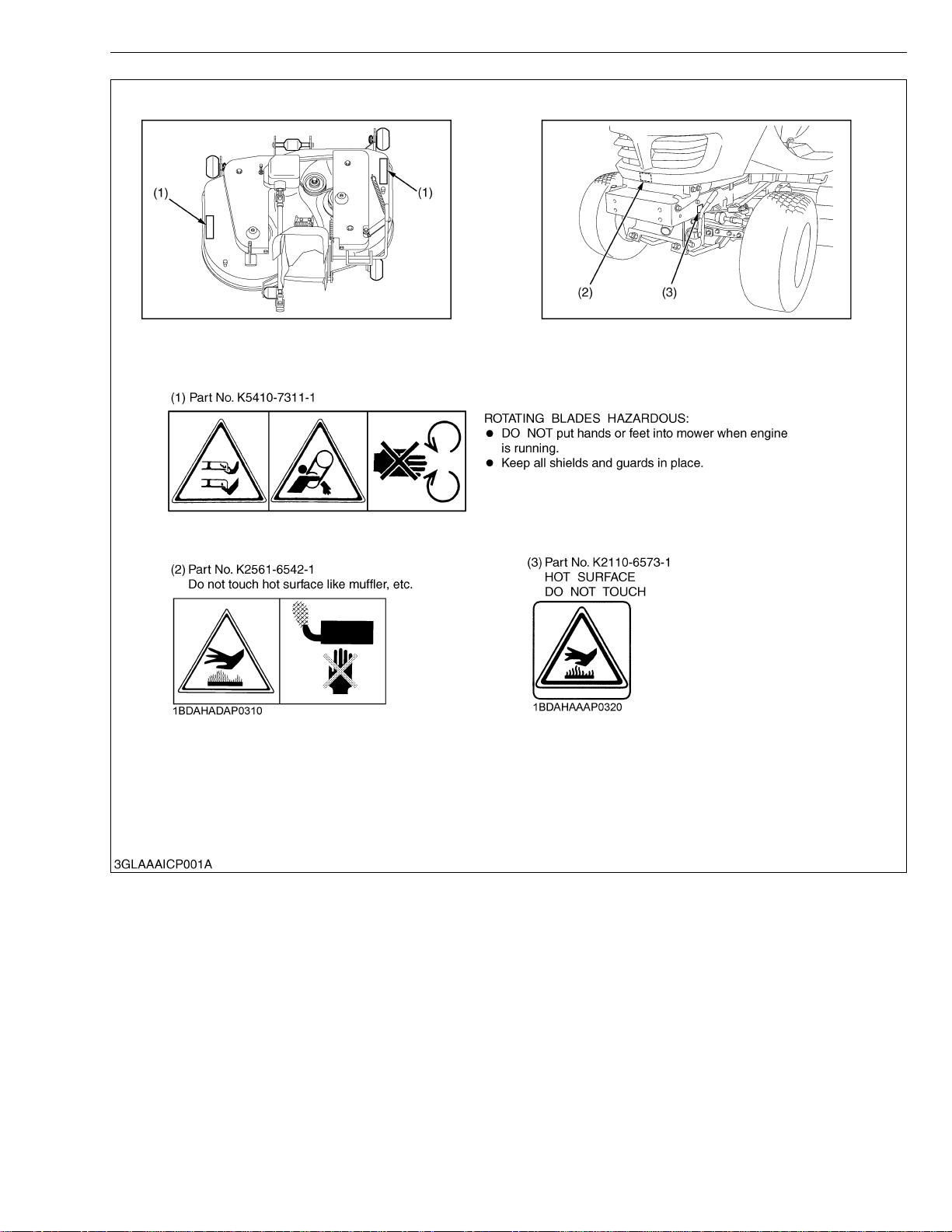
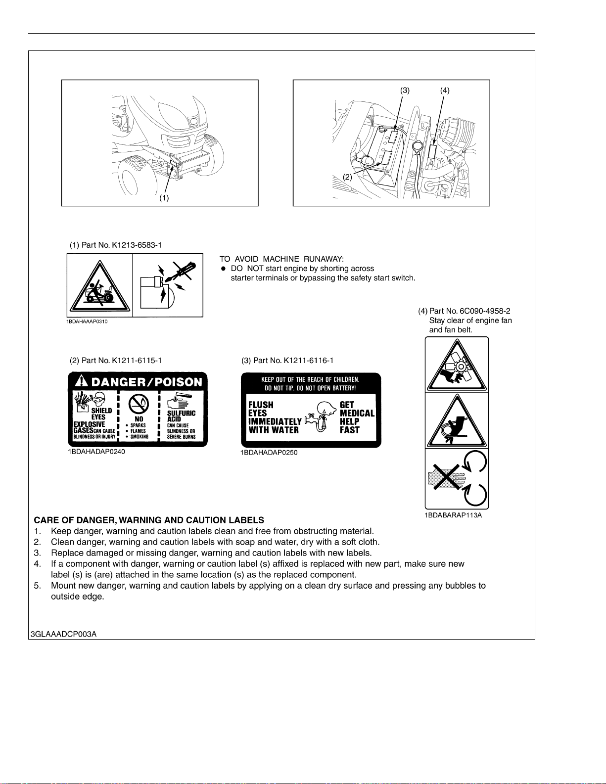
SAFETY DECALS
The following safety decals are installed on the machine. If a decal becomes damaged, illegible or is not on
the machine, replace it. The decal part number is listed in the parts list.
4
GR1600EC2, WSM
KiSC issued 07, 2006 A
SAFETY INSTRUCTIONS
5
GR1600EC2, WSM
KiSC issued 07, 2006 A
SAFETY INSTRUCTIONS
6

GR1600EC2, WSM
KiSC issued 07, 2006 A
SPECIFICATIONS
Model GR1600EC2
Maker KUBOTA
Model Z482-E2-GX
Type Indirect injection. Vertical, water-cooled, 4-cycle diesel
Number of cylinders 2
Bore and stroke 67 x 68 mm (2.64 x 2.68 in.)
Total displacement 479 cm
Engine
Capacities
Dimensions
Weight (without mower and grass catcher) 310 kg (684 lbs)
Traveling system
PTO system
NOTE: *Manufacture's estimate
The company reserves the right to change the specifications without notice.
Engine gross power (DIN) 10.0 kW (13.4 HP)
Rated revolution 53.3 r/s [3200 min
Battery 51R (12 V, 450CCA)
Starting system Cell starter (with glow plug)
Lubrication system Forced lubrication by trochoidal pump
Cooling system Pressurized radiator, forced circulation with water pump
Fuel
Fuel tank 18 L (4.8 U.S.gals, 4.0 lmp.gals)
Engine crankcase (with filter) 1.2 L (1.27 U.S.qts., 1.06 lmp.qts.)
Engine coolant (with recovery tank) 2.15 L (2.27 U.S.qts., 1.89 lmp.qts.)
Transmission case 2.7 L (0.71 U.S.gals., 0.59 lmp.gals.)
Overall length (with grass catcher) 2710 mm (107 in.)
Overall width 1110 mm (43.7 in.)
Overall height 1190 mm (46.9 in.)
Wheel base 1280 mm (50.4 in.)
Tread
Tires
Steering Manual (Sector gear type)
Transmission Hydrostatic transmission
Brake Internal expanding brake
Differential Bevel gear
Traveling speed
Clutch M echanical wet multi discs
PTO brake Wet multi discs
Front 750 mm (29.5 in.)
Rear 800 mm (31.5 in.)
Front 15 x 6.00 - 6, 4PR
Rear 20 x 10.00 - 8, 4PR
Forward 0.0 to 10.0 km/h (0.0 to 6.2 mph)
Reverse 0.0 to 5.0 km/h (0.0 to 3.1 mph)
Diesel fuel No.2-D [above -10 °C (14 °F)],
Diesel fuel No.1-D [below -10 °C (14 °F)]
3
(29.9 cu.in.)
-1
(rpm)]
SPECIFICATIONS
W1028280
7
GR1600EC2, WSM
KiSC issued 07, 2006 A
Model RCK42GREC2
Cutting width 1067 mm (42.0 in.)
Cutting height 25 to 102 mm (1 to 4 in.)
Adjustment of cutting height Dual gauge
Mounting method Quick joint, Parallel linkage
Mower
Grass catcher
NOTE: *Manufacture's estimate
The company reserves the right to change the specifications without notice.
Weight (Approx.) 75 kg (165 lbs)
Dimensions Total length 965 mm (38.0 in.)
Total width 1110 mm (43.7 in.)
Total height 295 mm (11.6 in.)
Discharge direction Rear
Gear box oil 0.33 L (0.35 U.S.qts, 0.29 Imp.qts)
Model GCK370GREC2
Container capacity 370 L (97.7 U.S.gals, 81.4 Imp.gals)
Weight (Approx.) 40 kg (88.2 lbs)
SPECIFICATIONS
W1030594
W1031306
8
GR1600EC2, WSM
KiSC issued 07, 2006 A
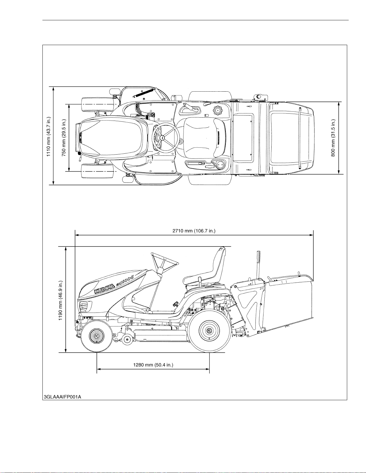
DIMENSIONS
DIMENSIONS
9

G GENERAL
KiSC issued 07, 2006 A

GENERAL
KiSC issued 07, 2006 A
CONTENTS
1. IDENTIFICATION............................................................................................. G-1
2. GENERAL PRECAUTIONS ............................................................................ G-2
3. HANDLING PRECAUTIONS FOR ELECTRICAL PARTS AND WIRING..G-3
[1] WIRING...................................................................................................... G-3
[2] BATTERY................................................................................................... G-5
[3] FUSE.......................................................................................................... G-5
[4] CONNECTOR............................................................................................ G-5
[5] HANDLING OF CIRCUIT TESTER......................................................... G-7
4. LUBRICANTS, FUEL AND COOLANT ......................................................... G-8
5. TIGHTENING TORQUES ............................. ....... ...... ....... ...... ....... ...... ....... .... G- 9
[1] GENERAL USE SCREWS, BOLTS AND NUTS................................... G-9
[2] METRIC SCREWS, BOLTS AND NUTS ............................................... G-9
[3] AMERICAN STANDARD SCREWS, BOLTS AND NUTS WITH UNC
OR UNF THREADS ............................................................................... G-10
[4] PLUGS..................................................................................................... G-10
6. MAINTENANCE CHECK LIST..................................................................... G-11
7. CHECK AND MAINTENANCE......... ...... ...... ....... ...... ....... ...... ....... ............... G-13
[1] DAILY CHECK........................................................................................ G-13
[2] CHECK POINTS OF EVERY 50 HOURS........................................... G-19
[3] CHECK POINTS OF EVERY 100 HOURS......................................... G-26
[4] CHECK POINT OF EVERY 150 HOURS ........................................... G-28
[5] CHECK POINTS OF EVERY 200 HOURS......................................... G-28
[6] CHECK POINT OF EVERY 400 HOURS ........................................... G-31
[7] CHECK POINT OF 1500 HOURS........................................................ G-32
[8] CHECK POINTS OF EVERY 1 YEAR ................................................ G-32
[9] CHECK POINTS OF EVERY 2 YEARS.............................................. G-34
[10]OTHERS .................................................................................................. G-35
8. SPECIAL TOOLS.......................................................................................... G-38
[1] SPECIAL TOOLS FOR ENGINE .......................................................... G-38
[2] SPECIAL TOOLS FOR MACHINE........................................................ G-43
9. TIRES............................................................................................................. G-46
[1] TIRE PRESSURE................................................................................... G-46
[2] TREAD..................................................................................................... G-46
10. IMPLEMENT LIMITATIONS.......................................................................... G-47
GR1600EC2, WSM
KiSC issued 07, 2006 A
1. IDENTIFICATION
G GENERAL
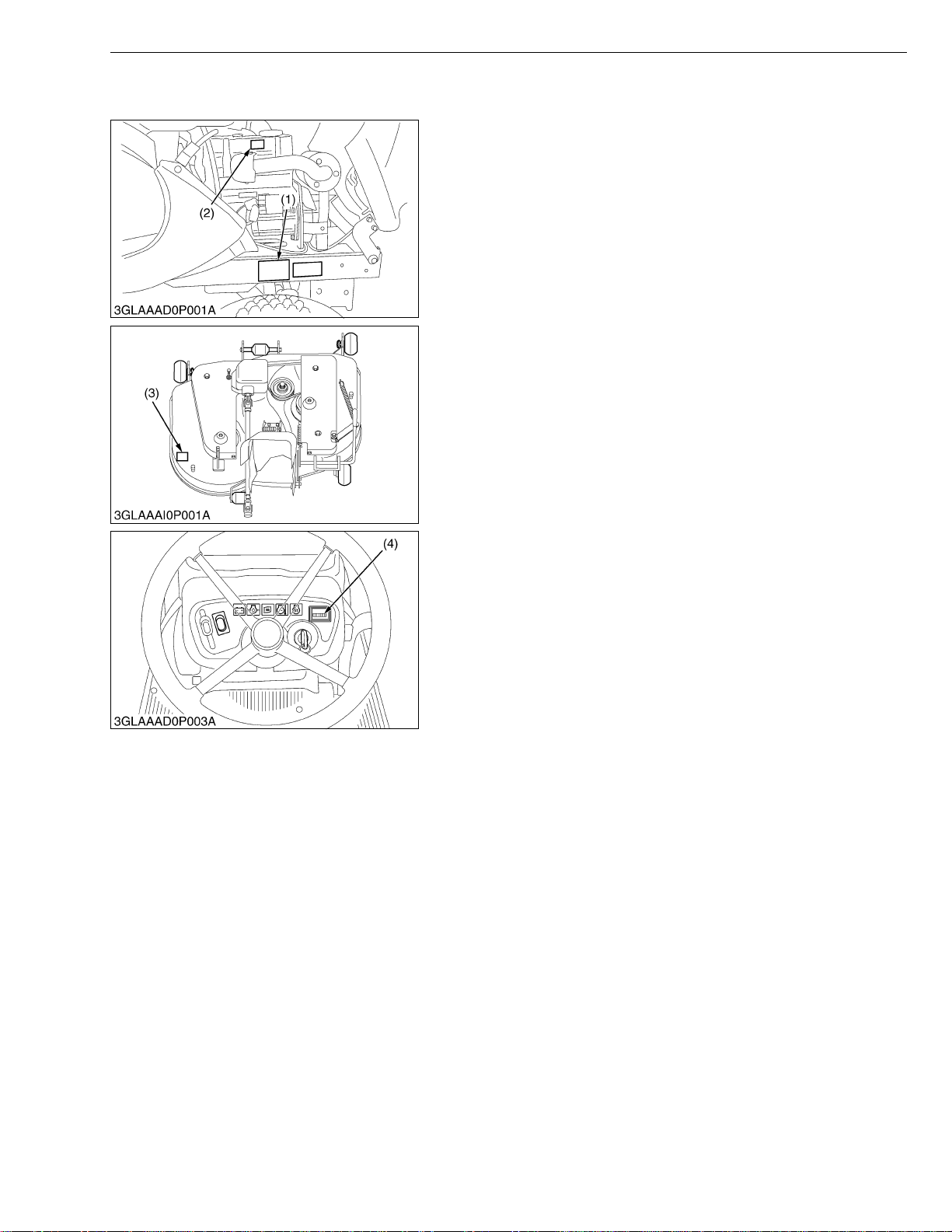
When contacting your loca l KUBOTA distr ibutor, alway s specify
engine serial num ber (2), machine serial number (1 ), mower serial
number (3) and hour meter reading.
(1) Machine Serial Number
(2) Engine Serial Number
(3) Mower Serial Number
(4) Hour Meter
W1010594
G-1
GR1600EC2, WSM
KiSC issued 07, 2006 A
2. GENERAL PRECAUTIONS
• During disa ssembly, ca refully ar range removed parts in a cle an
area to prevent confusion later. Screws, bolts and nuts should be
installed in their original position to prevent reassembly errors.
• When special tools are requi red, use KUBOT A genuine speci al
tools. Special tools which are not frequently used should be
made according to the drawings provided.
• Before disassembling or servicing electrical wires, always
disconnect the ground cable from the battery first.
• Remove oil and dirt from parts before measuring.
• Use only KUBOTA genuine parts for parts replacement to
maintain machine performance and to assure safety.
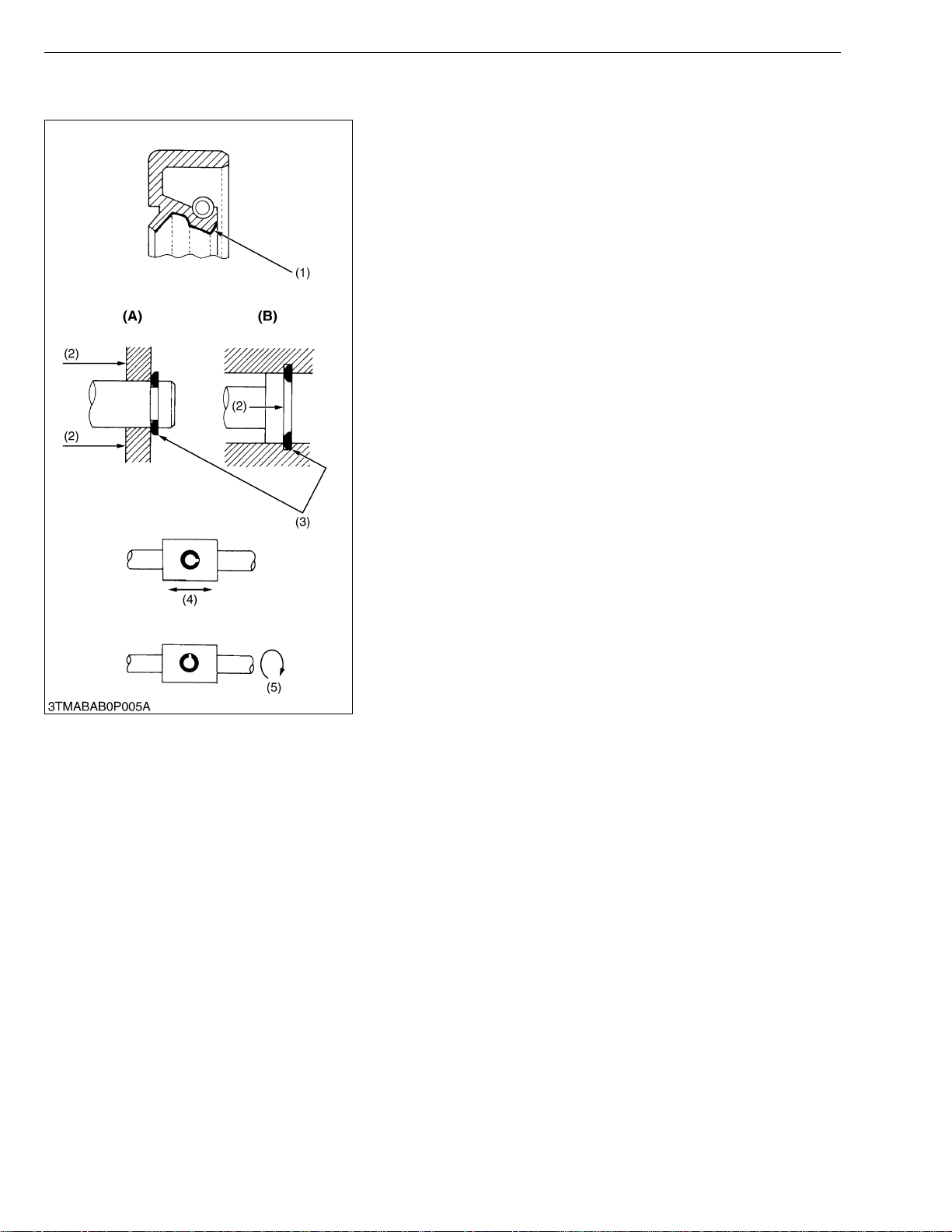
• Gaskets and O-rings must be replaced during reassembly.
Apply grease to new O-rings or oil seals before assembling.
See the figure left side.
• When reassembling external snap rings (A) or internal snap rings
(B), they must be positioned so that sharp edge faces against the
direction from which a force is applied. See the figure left side.
• When insert ing spring pins, their splits must face the direction
from which a force is applied. See the figure left side.
• To prevent dam age to the hydraulic s ystem, use only sp ecified
fluid or equivalent.
(1) Grease
(2) Force
(3) Sharp Edge
(4) Axial Force
(5) Rotating Movement
G GENERAL
(A) External Snap Ring
(B) Internal Snap Ring
W10109040
G-2
GR1600EC2, WSM
IMPORTANT■
KiSC issued 07, 2006 A
G GENERAL
3. HANDLING PRECAUTIONS FOR ELECTRICAL PARTS
AND WIRING
To ensure safety and prevent damage to the machine and
surrounding equipm ent, heed the following pr ecautions in handling
electrical parts and wiring.
• Check electrical wiring for damage and loosened
connection every year. To this end, educate the customer to
do his or her own check and at the s ame time recommend
the dealer to perform periodic check for a fee.
• Do not attempt to modify or remodel any electrical parts and
wiring.
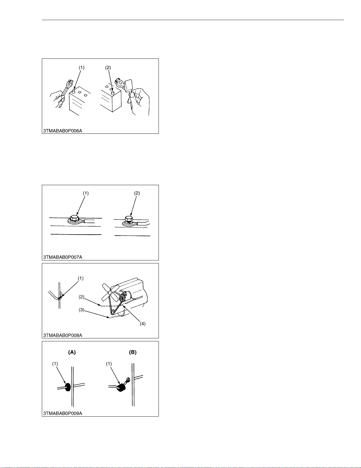
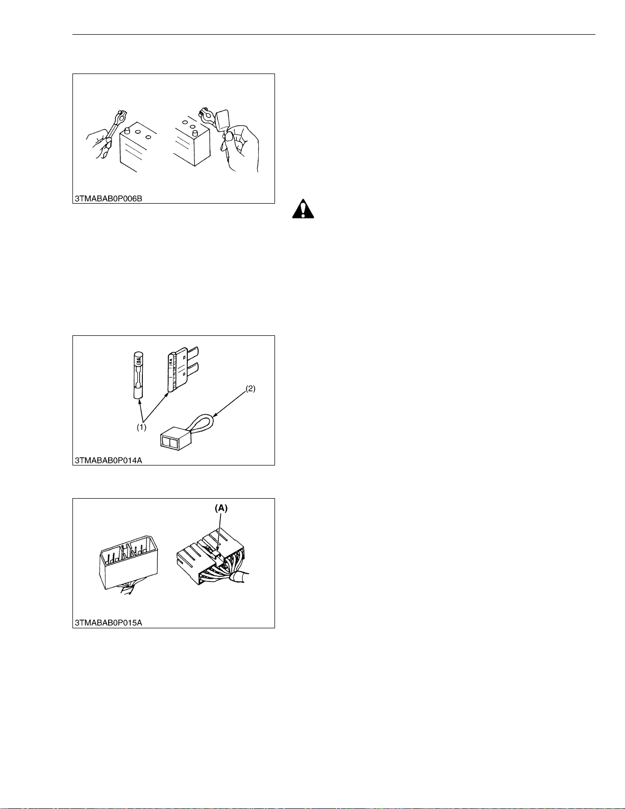
• When removing th e ba tter y cab le s, dis co nn ect t he n egat ive
cable first. When in stalling the b attery cables, c onnect the
positive cable first.
(1) Negative Terminal (2) Positive Terminal
W10111140
[1] WIRING
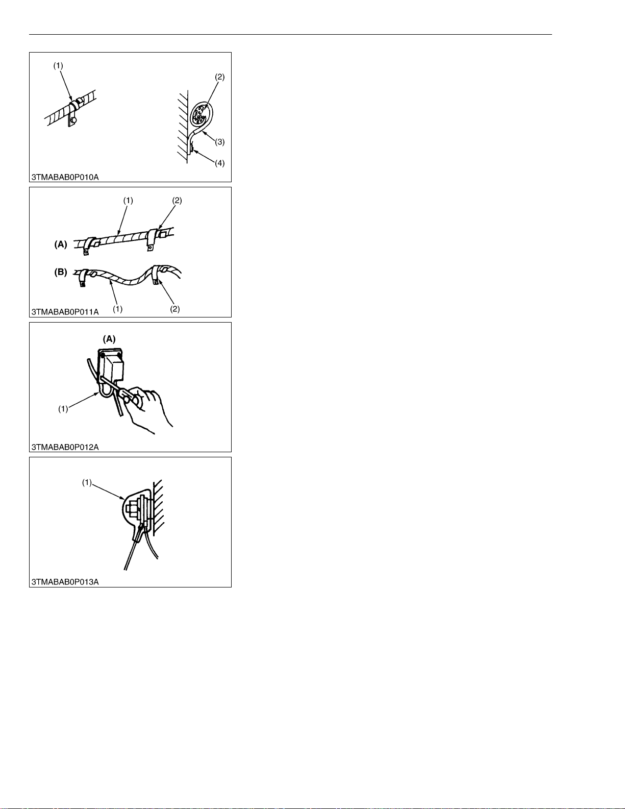
• Securely t ighten wiring terminals.
(1) Correct
(Securely Tighten)
(2) Incorrect
(Loosening Leads to Faulty Contact)
W10112160
• Do not let wiring contact dangerous part.
(1) Dangerous Part
(2) Wiring (Incorrect)
(3) Wiring (Correct)
(4) Dangerous Part
• Securely insert grommet.
(1) Grommet (A) Correct
(B) Incorrect
W10113130
W10113880
G-3
GR1600EC2, WSM
KiSC issued 07, 2006 A
G GENERAL
• Securely clamp, being careful not to damage wiring.
(1) Clamp
• Wind Clamp Spirally
(2) Wire Harness
(3) Clamp
(4) Welding Dent
W10114580
• Clamp wiring so that there is no twist, unnecessary sag, or
excessive tension, except for movable part, where sag be
required.
(1) Wiring
(2) Clamp
(A) Correct
(B) Incorrect
W10115870
• In installing a part, take care not to get wiring caught by it.
(1) Wiring (A) Incorrect
W10116700
• After installing wiring, check protection of terminals and clamped
condition of wiring, only connect battery.
(1) Cover
• Securely Install Cover
W10117350
G-4
GR1600EC2, WSM
KiSC issued 07, 2006 A
[2] BATTERY
[3] FUSE
G GENERAL
• Take care not to confuse positive and negative terminal posts.
• When removing b attery cables, disconnect negative cable first.
When installing battery cables, check for polarity and connect
positive cable first.
• Do not install a ny battery with capacity other than is specified
(Ah).
• After connecting cables to battery terminal posts, apply high
temperature grease to them a nd sec urely in stall t erminal covers
on them.
• Do not allow dirt and dust to collect on battery.
CAUTION
• Take care not to let battery liquid spill on your skin and
clothes. If contaminated, wash it off with water immediately.
• Before recharging the battery, remove it from the machine.
• Before recharging, remove cell caps.
• Do recharging in a well- ventilated place where there is no
open flame nearby, as hydrogen gas and oxygen are formed.
W10118160
[4] CONNECTOR
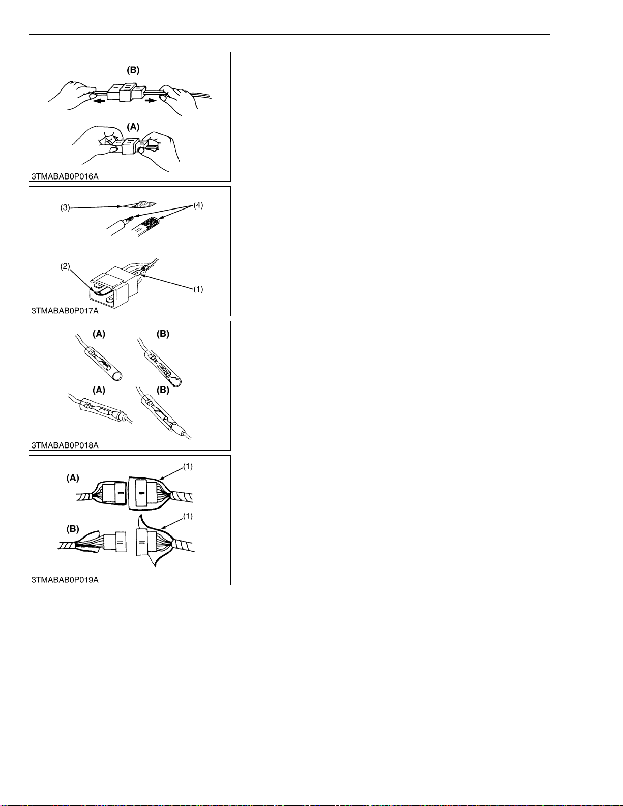
• Use fuses with specified capacity.
Neither too large or small capacity fuse is acceptable.
• Never use steel or copper wire in place of fuse.
• Do not install working light, radio set, etc. on machine which is not
provided with reserve power supply.
• Do not install accessories if fuse capacity of reserve power
supply is exceeded.
(1) Fuse (2) Fusible Link
W10120920
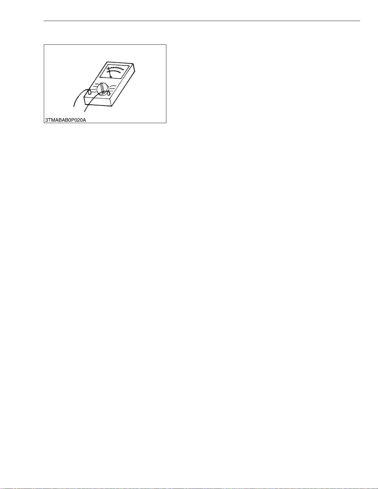
• For connector with lock, push lock to separate.
(A) Push
W10122110
G-5
GR1600EC2, WSM
KiSC issued 07, 2006 A
G GENERAL
• In separating connectors, do not pull wire harnesses.
• Hold connector bodies to separate.
(A) Correct (B) Incorrect
W10122720
• Use sandpaper to remove rust from terminals.
• Repair deformed terminal. Make certain there is no terminal
being exposed or displaced.
(1) Exposed Terminal
(2) Deformed Terminal
(3) Sandpaper
(4) Rust
W10123460
• Make certain that there is no female connector being too open.
(A) Correct (B) Incorrect
W10124300
• Make certain plastic cover is large enough to cover whole
connector.
(1) Cover (A) Correct
(B) Incorrect
W10125190
G-6
GR1600EC2, WSM
KiSC issued 07, 2006 A
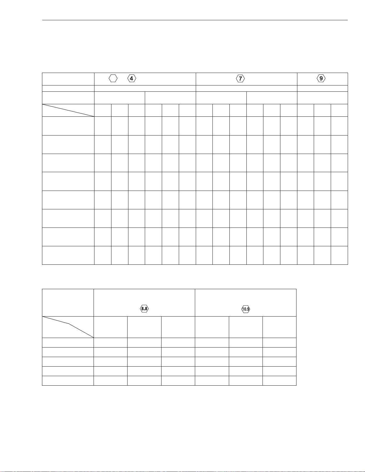
[5] HANDLING OF CIRCUIT TESTER
• Use tester correctly following manual provided with tester.
• Check for polarity and range.
G GENERAL
W10126840
G-7

GR1600EC2, WSM
KiSC issued 07, 2006 A
G GENERAL
4. LUBRICANTS, FUEL AND COOLANT
No. Place Capacity Lubricants, fuel and coolant
18 L
1 Fuel tank
Cooling system
2
with recovery tank
3 Engine crankcase
4 T ransmission case
5 Mower gear box
No. Place No. of greasing points Capacity Type of grease
Engine
6
transmission
universal joint
7 King pin 2
8 Center pin –
Speed control
9
pedal shaft
10 Mower link –
11 Seat adjuster –
12 Cable –
13 PTO lever –
14 Hydraulic lift lever –
Grass catcher
15
hinge
[Mower]
16 Spindle shafts 2
17 Tension arm 1
Mower universal
18
joint
* KUBOTA original transmission hydraulic fluid.
4.8 U.S.gals.
4.0 lmp.gals.
2.15 L
2.27 U.S.qts.
1.89 lmp.qts.
1.2 L
1.27 U.S.qts.
1.06 lmp.qts.
2.7 L
0.71 U.S.gals.
0.59 lmp.gals.
0.33 L
0.35 U.S.qts.
0.29 lmp.qts.
Greasing
1
–
–
1 Moderate amount
No. 2-D diesel fuel
No. 1-D diesel fuel if temperature is below −10 °C
(14 °F)
Fresh clean water with anti-freeze
Engine oil : API service CD, CE or CF
Below 0 °C (32 °F) : SAE10W, 10W-30 or 10W-40
0 to 25 °C (32 to 77 °F) : SAE20, 10W-30 or 10W40
Above 25 °C (77 °F) : SAE30, 10W-30 or 10W-40
KUBOTA UDT or SUPER UDT fluid*
SAE90 gear oil
(API service classification : more than GL-3)
Until grease overflows
Moderate amount Engine oil
Until grease overflows
SAE multi-purpose
type grease
SAE multi-purpose
type grease
Engine oil
G-8
GR1600EC2, WSM
KiSC issued 07, 2006 A
G GENERAL
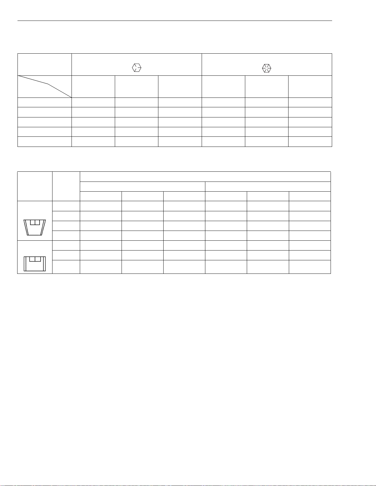
5. TIGHTENING TORQUES
[1] GENERAL USE SCREWS, BOLTS AND NUTS
Screws, bolts and nu ts whose tightening torques are not speci fied in t his Worksh op Manual should b e tightened
according to the table below.
Indication on top of
bolt
Material of bolt SS400, S20C S43C, S48C SCr435, SCM435
Material of opponent
part
Unit
Diameter
M6
(6 mm, 0.24 in.)
M8
(8 mm, 0.31 in.)
M10
(10 mm, 0.39 in.)
M12
(12 mm, 0.47 in.)
M14
(14 mm, 0.55 in.)
M16
(16 mm, 0.63 in.)
M18
(18 mm, 0.71 in.)
M20
(20 mm, 0.79 in.)
No-grade or 4T 7T 9T
Ordinariness Aluminum Ordinariness Aluminum Ordinariness
N·m kgf·m ft-lbs N·m kgf·m ft-lbs N·m kgf·m ft-lbs N·m kgf·m ft-lbs N·m kgf·m ft-lbs
7.85
0.80
5.79
7.85
0.80
5.79
9.81
1.00
7.24
7.85
0.80
5.79
12.3
to
9.31
17.7
to
20.5
39.3
to
45.1
62.8
to
72.5
108
to
125
167
to
191
246
to
284
334
to
392
to
0.95
1.8
to
2.1
4.0
to
4.6
6.4
to
7.4
11.0
to
12.8
17.0
to
19.5
25.0
to
29.0
34.0
to
40.0
to
6.87
13.1
to
15.1
29.0
to
33.2
46.3
to
53.5
79.6
to
92.5
123
to
141
181
to
209
246
to
289
to
to
8.82
0.90
16.7
19.6
31.4
34.3
1.7
to
2.0
3.2
to
3.5
–––
–––
–––
–––
–––
to
6.50
12.3
to
to
14.4
23.2
to
to
25.3
to
11.2
23.6
to
27.4
48.1
to
55.8
77.5
to
90.2
124
to
147
197
to
225
275
to
318
368
to
431
to
1.15
2.4
to
2.8
4.9
to
5.7
7.9
to
9.2
12.6
to
15.0
20.0
to
23.0
28.0
to
32.5
37.5
to
44.0
to
8.31
17.4
to
20.2
35.5
to
41.2
57.2
to
66.5
91.2
to
108
145
to
166
203
to
235
272
to
318
to
to
8.82
0.90
17.7
20.5
39.3
44.1
62.8
72.5
1.8
to
2.1
4.0
to
4.5
6.4
to
7.4
–––
–––
–––
–––
to
6.50
13.1
to
to
15.1
29.0
to
to
32.5
46.3
to
to
53.5
to
14.2
29.5
to
34.3
60.9
to
70.6
103
to
117
167
to
196
260
to
304
344
to
402
491
to
568
1.25
to
1.45
3.0
to
3.5
6.2
to
7.2
10.5
to
12.0
17.0
to
20.0
26.5
to
31.0
35.0
to
41.0
50.0
to
58.0
W1034542
9.05
to
10.4
21.7
to
25.3
44.9
to
52.0
76.0
to
86.7
123
to
144
192
to
224
254
to
296
362
to
419
[2] METRIC SCREWS, BOLTS AND NUTS
Property class 8.8 Property class 10.9
Grade
Unit
Nominal
Diameter
M 8 23.6 to 27.4 2.4 to 2.8 17.4 to 20.2 29.4 to 34.3 3.0 to 3.5 21.7 to 25.3
M 10 48.1 to 55.8 4.9 to 5.7 35.5 to 41.2 60.8 to 70.5 6.2 to 7.2 44.9 to 52.1
M 12 77.5 to 90.1 7.9 to 9.2 57.2 to 66.5 103.0 to 117.0 10.5 to 12.0 76.0 to 86.8
M 14 124.0 to 147.0 12.6 to 15.0 91.2 to 108.0 167.0 to 196.0 17.0 to 20.0 123.0 to 144.0
M 16 196.0 to 225.0 20.0 to 23.0 145.0 to 166.0 260.0 to 303.0 26.5 to 31.0 192.0 to 224.0
N·m kgf·m ft-lbs N·m kgf·m ft-lbs
W1016172
G-9
GR1600EC2, WSM
KiSC issued 07, 2006 A
G GENERAL
[3] AMERICAN STANDARD SCREWS, BOLTS AND NUTS WITH UNC OR
UNF THREADS
Grade
Unit
Nominal
Diameter
5/16 23.1 to 27.8 2.35 to 2.84 17.0 to 20.5 32.5 to 39.3 3.31 to 4.01 24.0 to 29.0
3/8 47.5 to 57.0 4.84 to 5.82 35.0 to 42.0 61.0 to 73.2 6.22 to 7.47 45.0 to 54.0
1/2 108.5 to 130.2 11.07 to 13.29 80.0 to 96.0 149.2 to 179.0 15.22 to 18.27 110.0 to 132.0
9/16 149.2 to 179.0 15.22 to 18.27 110.0 to 132.0 217.0 to 260.4 22.14 to 26.57 160.0 to 192.0
5/8 203.4 to 244.1 20.75 to 24.91 150.0 to 180.0 298.3 to 358.0 30.44 to 36.53 220.0 to 264.0
[4] PLUGS
Shape Size
Tapered
screw
Straight
screw
SAE GR.5 SAE GR.8
N·m kgf·m ft-lbs N·m kgf·m ft-lbs
W1022485
Material of opponent part
Ordinariness Aluminum
N·m kgf·m ft-lbs N·m kgf·m ft-lbs
R1/8 12.7 to 21.6 1.3 to 2.2 9.4 to 15.9 12.7 to 19.6 1.3 to 2.0 9.4 to 15.4
R1/4 24.5 to 44.1 2.5 to 4.5 18.1 to 32.5 24.5 to 34.3 2.5 to 3.5 18.1 to 25.4
R3/8 49.0 to 88.3 5.0 to 9.0 36.2 to 65.1 49.0 to 58.8 5.0 to 6.0 36.2 to 43.4
R1/2 58.8 to 107.9 6.0 to 11.0 43.4 to 79.6 58.8 to 78.5 6.0 to 8.0 43.4 to 57.9
G1/4 24.5 to 34.3 2.5 to 3.5 18.1 to 25.3 – – –
G3/8 61.8 to 82.4 6.3 to 8.4 45.6 to 60.8 – – –
G1/2 49.0 to 88.3 5.0 to 9.0 36.2 to 65.1 – – –
0000001666E
G-10

GR1600EC2, WSM
■
KiSC issued 07, 2006 A
G GENERAL
6. MAINTENANCE CHECK LIST
IMPORTANT
• The jobs indicated by ★ must be done initially.
• *1 : This maintenance should be done daily more often in dusty conditions than in normal conditions.
Suggested cleaning interval is every 100 hours in normal conditions.
Period
No.
Item
1 Engine oil Change ★✩✩✩✩
2 Engine oil filter Replace ★✩ ✩ ✩
3 Transmission fluid Change ★✩✩
4 Transmission oil filter Replace ★✩ ✩ ✩
5 Transmission strainer Clean ★✩✩
6 Front axle pivot Adjust ★✩ ✩ ✩
Safety device
7
Oiling
8
9 Greasing – ✩✩
Mower gear box oil
10
Air cleaner element
11
Battery condition
12
Brake
13
Fan drive belt tension
14
Fuel filter element
15
Check ✩✩✩✩✩✩✩✩✩✩✩✩
Check ✩✩
Change ✩✩✩✩✩
Clean ✩✩✩✩✩✩✩✩✩
Replace
Check ✩✩✩✩✩✩✩✩✩
Adjust ✩✩✩✩
Adjust ✩✩✩✩
Check ✩✩✩✩
Replace ✩
50 100 150 200 250 300 350 400 450 500 550 600
– ✩✩
Indication on hour meter (Hr)
✩
✩
✩
✩
✩
✩
✩
✩
✩
✩
✩
✩
After
Impor-
since
✩
✩
✩
✩
✩✩✩
✩
✩✩✩
✩
✩✩✩
✩
✩
✩
✩
✩
✩
✩✩
✩✩
every
✩
100 hr
every
200 hr
every
200 hr
every
200 hr
every
200 hr
every
200 hr
every
50 hr
every
✩
50 hr
every
✩
50 hr
every
✩
50 hr
every
150 hr
every
50 hr
every
1 year
every
50 hr
every
✩
100 hr
every
✩
100 hr
every
✩
100 hr
every
400 hr
tant
*1 G-20
W1035769
Refer-
ence
page
G-26
G-28
G-29
G-30
G-30
G-31
G-19
G-21
G-20
G-20
G-28
G-32
G-24
G-27
G-28
G-27
G-31
G-11

GR1600EC2, WSM
KiSC issued 07, 2006 A
G GENERAL
Period
No.
Item
Fuel line
16
Radiator hose and clamp
17
Intake air line
18
Fuel injection nozzle
19
(Injection pressure)
Radiator
20
Coolant
21
Mower gear box oil seal
22
Fuse
23
Blade
24
Mower belt
25
Fuel system
26
Indication on hour meter (Hr )
50 100 150 200 250 300 350 400 450 500 550 600
Check ✩✩✩✩
Replace
Check ✩✩✩
Replace
Check ✩✩✩
Replace
Check
Clean
Change
Replace
Replace
Replace G-36
Replace G-37
Bleed G-37
✩
✩
After
since
every
100 hr
every
2 year
every
200 hr
every
2 year
every
200 hr
every
2 year
every
1500 hr
every
1 year
every
1 year
every
2 year
Service
as re-
quired
Impor-
tant
Refer-
ence
page
G-27
G-34
G-30
G-34
G-31
G-34
G-32
G-32
G-32
G-34
G-35
W1045250
G-12

GR1600EC2, WSM
KiSC issued 07, 2006 A
G GENERAL
7. CHECK AND MAINTENANCE
CAUTION
• Be sure to check and serv ice the machine on a flat pla ce with engine shu t off, the parking brak e on and
chock the wheels.
[1] DAILY CHECK
To prevent trouble from occurring, it is important to know the condition of the machine. Check the following items
before starting.
Checking
• Walk around the machine.
1. Tire pressure, wear and damage
2. Oil and water leak
3. Engine oil level
4. Transmission fluid level
5. Coolant level in the recovery tank
6. Damage of machine body, tightness of all bolts and nuts
7. Radiator screen
8. Panel screen
9. Brake play
10.Fuel level
11.C heck air cle ane r ele men t
•Mower
1. Oil leak
2. Make sure blade cap screws are tight.
3. Blades for wear or damage.
4. Check all hardware.
5. Make sure all pins are in place.
6. Mower deck cleaning
7. Greasing
• While sitting in the operator's seat,
1. Speed control pedal and brake pedal
2. Brake
• Turning the key switch “ON”
1. Performance of the easy checker light.
• Starting the engine
1. Color of the exhaust fumes
2. Safety start switch, seat safety control and another safety devices.
3. Check for abnormal noise and vibr ati on.
•Others
1. Check the areas where previous troubles were experienced.
G-13
GR1600EC2, WSM
KiSC issued 07, 2006 A
G GENERAL
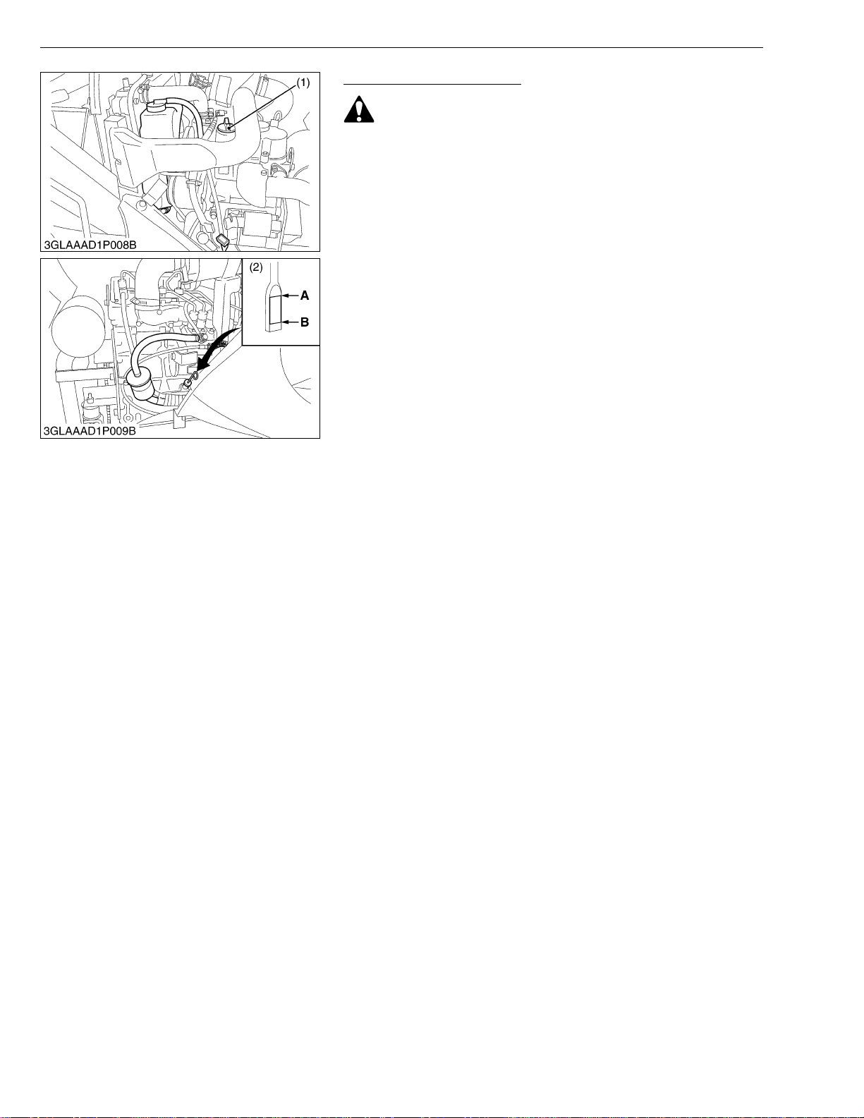
Checking Engine Oil Level
CAUTION
• Always stop the engine and remove the key before checking
oil.
1. Check engine oil before starting and 5 minutes or more after the
engine has stopped.
2. Wipe dipstick (2) area clean.
3. To check the oil level, remove the dipstick (2), wipe it clean,
reinsert it, and draw it out again . Check to see that the oil level
is between the two notches.
4. Add new oil to the prescribed level at the oil inlet (1) if necessary.
5. W hen using a different brand or viscosi ty oil from the previous
one, remove all of the old oil and oil filter. Never mix two different
types of oil.
6. Use the proper Engine Oil SAE according to the ambient
temperatures. (See page G-8.)
(1) Engine Oil Inlet
(2) Oil Level Dipstick
A : Upper Level
B : Lower Level
W1048088
G-14
GR1600EC2, WSM
IMPORTANT■
NOTE■
KiSC issued 07, 2006 A
G GENERAL
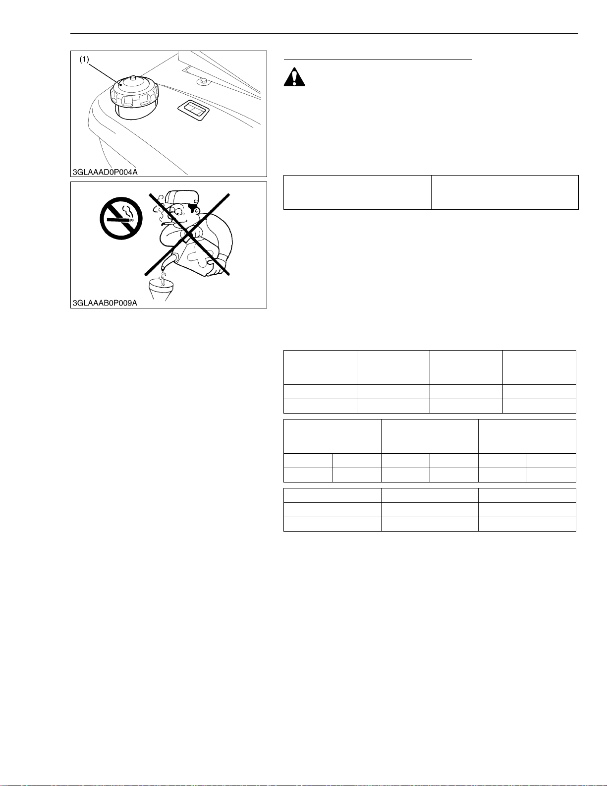
Checking Amount of Fuel and Refueling
CAUTION
• Handle fuel carefully. If the engine is running, do not fill the
fuel tank. If engine is hot, let engine cool several minutes
before adding fuel.
Do not smoke while filling the fuel tank or servicing the fuel
system. Fill fuel tank only to bottom of filler neck.
Check the fuel level. Take care that the fuel tank does not
become empty.
Fuel tank capacity
18 L
4.8 U.S.gals
4.0 Imp.gals
• Use Diesel fuel only
1. Use No.2-D diesel fuel.
2. Use No.1-D diesel fuel if the temperature is below –10 °C (14 °F).
3. Always use a strainer when refueling to prevent fuel injection
pump contamination.
• No.2-D is a distillate fuel of lower volatility for engines in
industrial and heavy mobile service.
(SAE J313 JUN87)
Grade of Diesel Fuel Oil according to ASTM D975
Flash Point °C
Min Max Max Max
52 0.05 0.35 0.01
Water and
Sediment,
volume %
Carbon Residue
on, 10 percent
Residuum %
Ash, weight %
Distillation
Temperatures °C 90 %
Point
Min Max Min Max Min Max
282 338 1.9 4.1 32.6 40.1
Sulfur, weight C opper strip Corrsion Catane Number
Max Max Min
0.50 No.3 40
(1) Fuel Cap
Kinematic Viscosity cSt
or mm
at 40 °C
2
/s
Saybolt Viscosity, SUS
at 100 °F
W1021324
G-15
GR1600EC2, WSM
■
KiSC issued 07, 2006 A
G GENERAL
Checking Cleaning Radiator to Prevent Overheating
CAUTION
• Be sure to stop the engine and remove the key before
cleaning.
Daily or after every 5 hour s of operation, check to be sure the
radiator screen (2) and radia tor c ore are c lean. Dir t or cha ff on the
radiator screen (2) or radiator core decrease cooling performance.
1. Remove the radiator screen (2) and panel screen (1) and remove
all foreign material.
2. Remove the dust from between the fins and the tube.
3. Tighten the fan drive belt as necessary. For this, refer to
"CHECK POINT EVERY 100 HOURS".
4. If scale forms in the tube, clean with the scale inhibitor or its
equivalent.
5. Each time the panel screen (1) is covered with grass during
operation, rub i t off the screen with hand. Check the radiator
screen (2) from time to time if grass accumulates.
6. I f the du st or chaff h as accumu lated i nside of the panel, re move
the radiator screen (2) and clean inside completely.
After cleaning, reinst all the radi ato r scr een (2 ) prope rly.
NOTE
• When assembling the panel screen (1), be sure to fit it to
panel with no clearance at the bottom.
(1) Panel Screen (2) Radiator Screen
W1049374
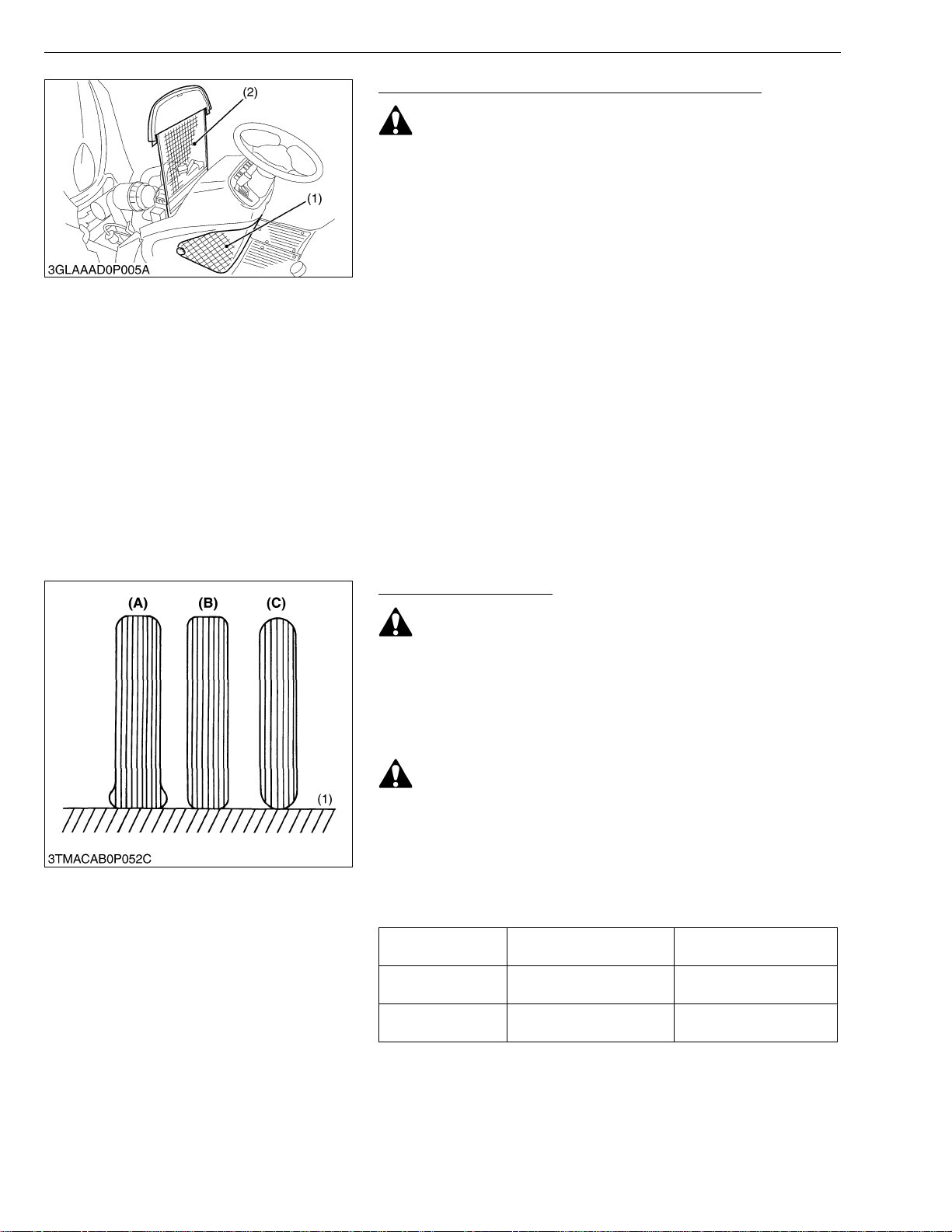
Checking Tire Pressure
WARNING
• Do not attempt to mount a tire on a rim. This should be done
by a qualified person with the proper equipment.
• Always maintain the correct tire pressure.
Do not inflate tires above the recommended pressure.
• Inflation pressure in front tires rises quickly when using
compressed air.
CAUTION
• Never operate machine with a loose rim, wheel or axle.
• Whenever bolts are loosened, retighten to specified torque.
• Check all bolts frequently and keep them tightened.
■ Inflation Pressure
Though the inflation pressure is factory-set to the prescribed
level, it naturally drops slowly in the cours e of time. Thus, check it
every day and inflate as necessary.
Tire sizes
Front 15 x 6.0-6, 4PR
Rear 20 x 10.00-8, 4PR
(1) Ground (A) Insufficient
(B) Normal
(C) Excessive
Recommended Inflation
Pressure
200 kPa
2
140 kPa
2
, 29 psi)
, 20 psi)
W1068933
(2.0 kgf/cm
(1.4 kgf/cm
G-16
GR1600EC2, WSM
IMPORTANT■
IMPORTANT■
KiSC issued 07, 2006 A
G GENERAL
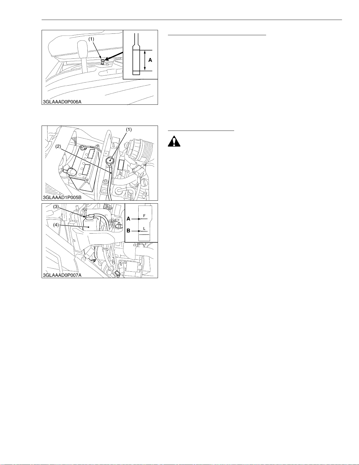
Checking Transmission Fluid Level
1. Park the machine on a flat surface, lower the imple ment to the
ground and shut off engine and remove the key.
2. Raise the operator's seat.
3. To che ck the oil level, draw out the dipstick (1), wipe it cl ean,
reinsert it, and d raw it out a gain. Chec k to see that th e oil lev el
lies between the two notches. If the level is too low, add new oil
to the prescribed level at the oil inlet. (See page G-8.)
• If oil level is low, do not run engine.
(1) Oil Level Dipstick A : Oil level is acceptable within this
range.
W1050686
Checking Coolant Level
CAUTION
• Do not remove the radiator cap when the engine is hot.
Loosen cap slightly, to the stop, to relieve any excess
pressure before removing cap completely.
Check the coolant le vel dai ly both t he radia tor and the r ecovery
tank (4) before starting engine.
1. Remov e the radiator cap (1) an d check to see that the cool ant
level is just below the fill port.
2. Check to see that the coolant le vel is between the "FULL" and
"LOW" marks of recovery tank (4).
3. When the coolant level drops due to evaporation, add water only
up to just below the fill port of the radiator and the full level of the
recovery tank (4).
In case of leakage, add coolant and water in the specified mixing
ratio up to the full level. (See page G-32.)
• If the radiator cap has to be removed, follow the caution
above and securely retighten the cap.
• Use clean, distilled coolant and water to fill the radiator and
recovery tank.
(1) Radiator Cap
(2) Overflow Pipe
(3) Recovery Tank Cap
(4) Recovery Tank
A : FULL
B : LOW
W1051701
G-17
 Loading...