

Kubota GL6000-STD, GL7000-USA, GL7000-USA-TM, GL7000-STD, GL9000-STD Operator's Manual
...
GL6000-STD · GL6000-AUS
GL7000-USA · GL7000-USA-TM · GL7000-STD
GL9000-STD · GL9000-AUS
GL11000-USA · GL11000-USA-TM · GL11000-STD
D-2396 D-2397
ENGLISH
To prevent electrical shock the following instruction must be followed.
Before the generator can be connected to a building’s electrical
system, a licensed electrician must install an isolation (transfer) switch
in the building’s main fuse box. The switch is the connection point for
generator power and allows selection of generator or main line power
to the building.
This will prevent the generator from charging the main power line
(backfeeding) when the main power supply has failed or has been
turned off for line repair. Backfeeding can electrocute or injure line
maintenance personnel. Also, generator and building electrical system
damage can occur when normal operating power returns if unit is used
without an isolation switch.
3
WARNING
WARNING
IMPORTANT
The engine in this machine is not equipped by the manufacture with
a standard spark arrester.
It is a violation of California Public Resource Code Section 4442 to
use or operate this engine on or near any forest-covered, brushcovered land, or grass- covered land unless the exhaust system is
equipped with a working spark arrester meeting state laws. Other
states or federal areas may have similar laws.
California Proposition 65
Engine exhaust, some of its constituents,
certain vehicle components and fluids,
contain or emit chemicals known to the
State of California to cause cancer and birth
defects or other reproductive harm.
WARNING

FOREWORD
3
DANGER :
3
WARNING :
3
CAUTION :
IMPORTANT :
NOTE :
3
SAFETY FIRST
You are now the proud owner of a KUBOTA Diesel Engine Generator. This
generator is a product of KUBOTA quality engineering and manufacturing. It
is made of fine materials and under a rigid quality control system with
correct maintenance. It will give you long, satisfactory service. To obtain the
best use of your generator, please read this manual carefully. It will help you
become familiar with the operation of the generator and contains many
helpful hints about generator maintenance. It is KUBOTA's policy to utilize as
quickly as possible every advance in our research. The immediate use of
new techniques in the manufacture of products may cause some small parts
of this manual to be outdated. KUBOTA distributors and dealers will have the
most up-to-date information. Please do not hesitate to consult with them.
This symbol, the industry's "Safety Alert Symbol", is used throughout this
manual and on labels on the machine itself to warn of the possibility of
personal injury. Read these instructions carefully. It is essential that you
read the instructions and safety regulations before you attempt to assemble
or use this unit.
Indicates an imminently hazardous situation which, if
not avoided, will result in death or serious injury.
Indicates a potentially hazardous situation which, if not
avoided, could result in death or serious injury.
Indicates a potentially hazardous situation which, if not
avoided, may result in minor or moderate injury.
Indicates that equipment or property damage could
result if instructions are not followed.
Gives helpful information.

CONTENTS
ENGLISH
SAFETY PRECAUTIONS ..................................................................................... 1
SERVICING OF GENERATOR ................................................................................. 1
SPECIFICATION ....................................................................................................... 2
NOMENCLATURE..................................................................................................... 4
GROUND FAULT CIRCUIT INTERRUPTER (GFCI) RECEPTACLE ....................... 8
PREPARATION TO SUPPLY THE ELECTRIC POWER ........................................ 10
CONNECTING THE LOAD...................................................................................... 12
PRE-OPERATION CHECK...................................................................................... 16
OPERATING THE GENERATOR............................................................................ 19
SERVICE INTERVALS ............................................................................................ 23
PERIODIC SERVICE ............................................................................................... 25
TRANSPORTING / STORAGE................................................................................ 37
TROUBLESHOOTING............................................................................................. 38
AUTOMATIC START/STOP UNIT (A S/S UNIT)..................................................... 40
WIRING DIAGRAM.................................................................................................. 41
1SAFETY PRECAUTIONS
ENGLISH
SAFETY PRECAUTIONS
A To operate the machine safely, be sure to follow the instructions below.
DANGER
To avoid personal injury:
A Hazard of being caught up in the machine: Do
not touch any rotating parts.
A Do not use or charge the battery if its fluid level
stands below the LOWER mark.
Otherwise, the component parts may deteriorate
earlier than expected, which may shorten the
service life or cause an explosion. Immediately,
add distilled water until the fluid level is between
the UPPER and LOWER levels. (for only refillable
battery)
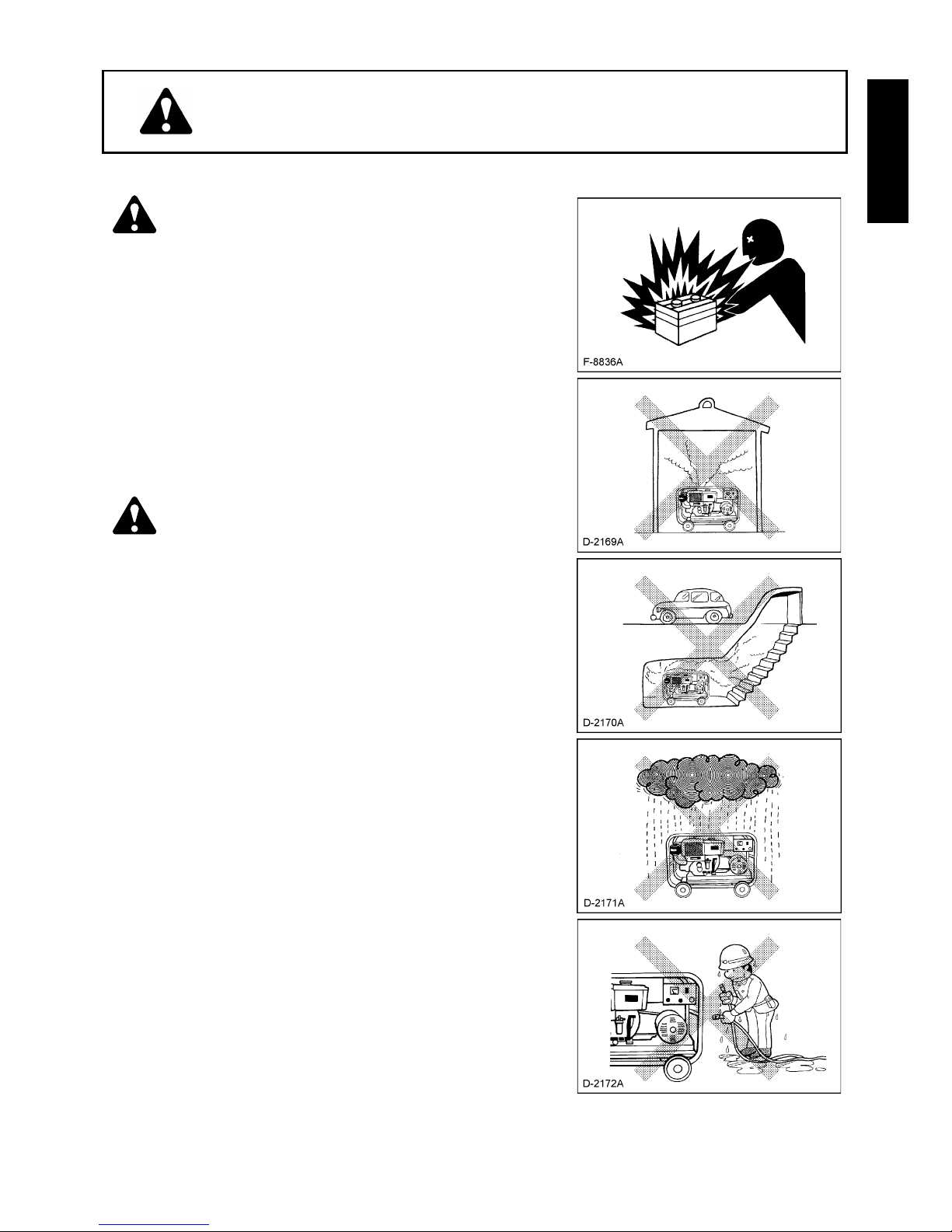
WARNING
To avoid personal injury:
A Exhaust gas poisoning hazard: Do not use the
machine in any poorly-ventilated place such as
indoors and tunnels.
A Exhaust gas poisoning and fire hazard: Do not
direct the exhaust to people and buildings.
A Electric shock hazard: Do not touch the machine
with wet hands.
A Electric shock hazard: Do not touch the
terminals and sockets while the machine is
running.
A Electric shock and injury hazard: Do not check
and service the machine while it is running.
A Electric shock and injury hazard: Do not tamper
with the machine.
A Fire hazard: Flames prohibited. Keep the
machine more than 1 m(3 feet) away from
flammable materials.
A Electric shock hazard: Do not use the machine in
the rain.
2 SAFETY PRECAUTIONS
ENGLISH
CAUTION
To avoid personal injury:
A Electric shock and fire hazard: Do not connect
the machine to any indoor (commercial) power
outlet.
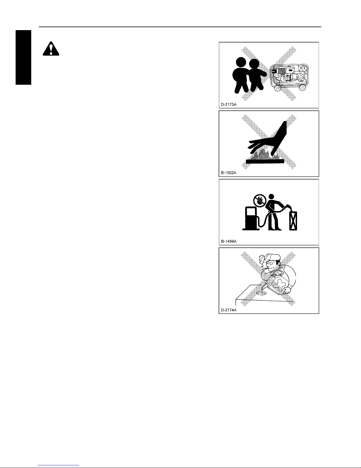
A Electric shock and injury hazard: Do not allow
children to run the machine.
A Electric shock and injury hazard: Turn off the
circuit breaker before starting the machine.
A Injury hazard: Do not touch the muffler.
A Injury hazard: Do not run the machine tilted.
A Injury hazard: Do not move the machine while it
is running.
A Fire hazard: Stop the engine before adding fuel.
A Fire hazard: Do not enclose the machine, nor
cover it with a box or the like.
A Fire hazard: Pay attention to the type and
amount of fuel.
A Do not get the warning label dirty or peeled off.
A Be sure to hand over the operation manual to
any other operator.
A Electric shock hazard: Ground the machine
using the ground terminal on the control panel.
3SAFETY PRECAUTIONS
ENGLISH
CAUTION
To avoid personal injury:
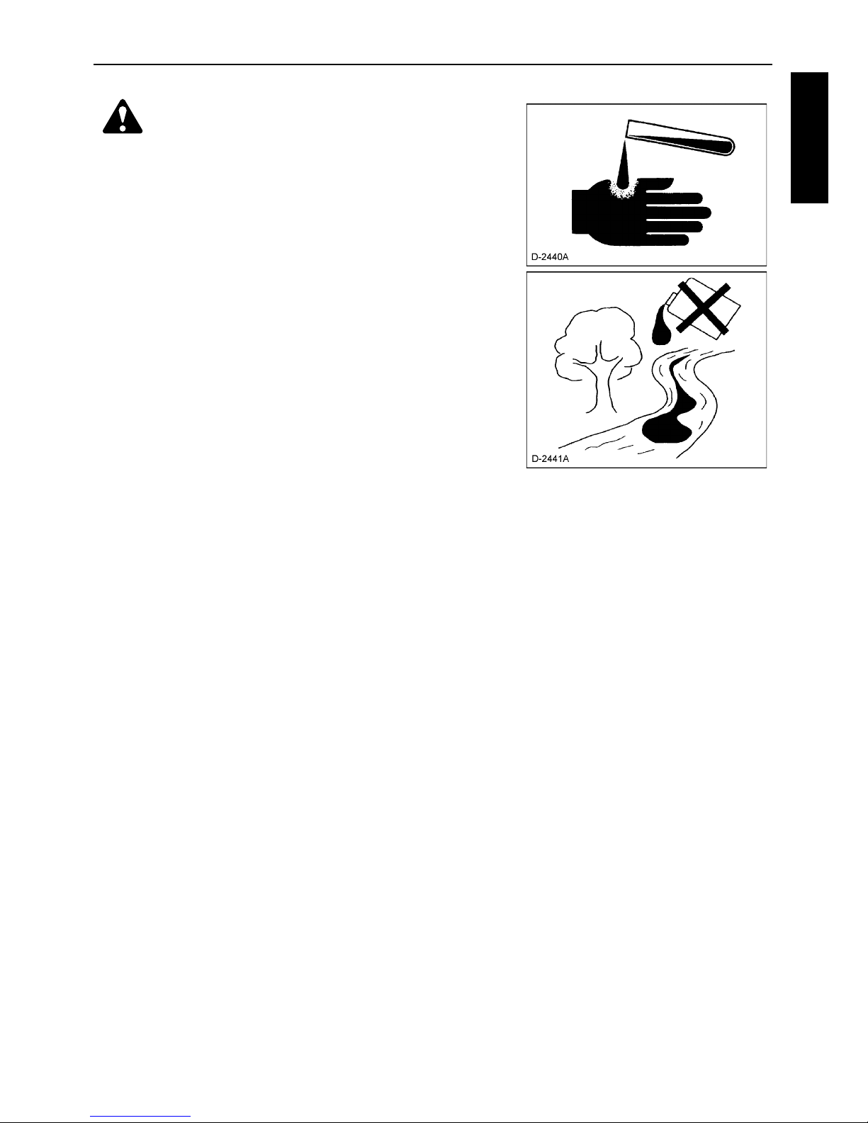
A Anti-freeze contains poison. Wear rubber gloves
to avoid personal injury. In case of contact with
skin, wash it off immediately.
A DO NOT mix different types of Anti-freeze. The
mixture can produce chemical reaction causing
harmful substances. Use approved Anti-freeze.
A Be mindful of the environment and the ecology.
Before draining any fluids, find out the correct
way of disposing of them. Observe the relevant
environmental protection regulations when
disposing of oil, fuel, coolant, brake fluid, filters
and batteries.
A When draining fluids from the engine, place
some container underneath the engine body.
A DO NOT pour waste onto the grounds, down a
drain, or into any water source.
4 SAFETY PRECAUTIONS
ENGLISH
CAUTION
To avoid personal injury:
A When checking engine or servicing, place the
engine on a wide and level ground. DO NOT work
on anything that is supported ONLY by lift jacks
or a hoist. Always use blocks or correct stands
to support the engine before servicing.
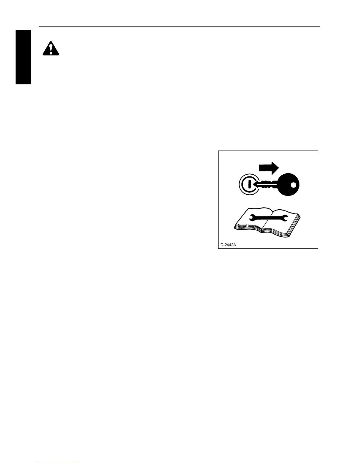
A Detach the battery from the engine before
conducting service. Put a "DO NOT OPERATE!"
tag in the key switch to avoid accidental starting.
A To avoid sparks from an accidental short circuit
always disconnect the battery's ground cable (-)
first and connect it last.
A Be sure to stop the engine and remove the key
when conducting daily and periodic
maintenance, servicing and cleaning.
A Check or conduct maintenance after the engine,
coolant, muffler, or muffler cover have been
cooled off completely.
A Always use the appropriate tools and jig-fixture
in good condition when performing any service
work. Make sure you understand how to use
them before service.
A Use ONLY correct engine barring techniques for
manually rotating the engine. DO NOT attempt to
rotate the engine by pulling or prying on the
cooling fan and V-belt. This practice can cause
serious personal injury or premature machine
damage to the cooling fan.
A Replace fuel pipes and lubricant pipes with their
hose clamps every 2 years or earlier whether
they are damaged or not. They are made of
rubber and are aged gradually.
A When servicing is performed together by two or
more persons, take care to perform all work
safely.
A Keep first aid kit and fire extinguisher handy at
all times.
5SAFETY PRECAUTIONS
ENGLISH
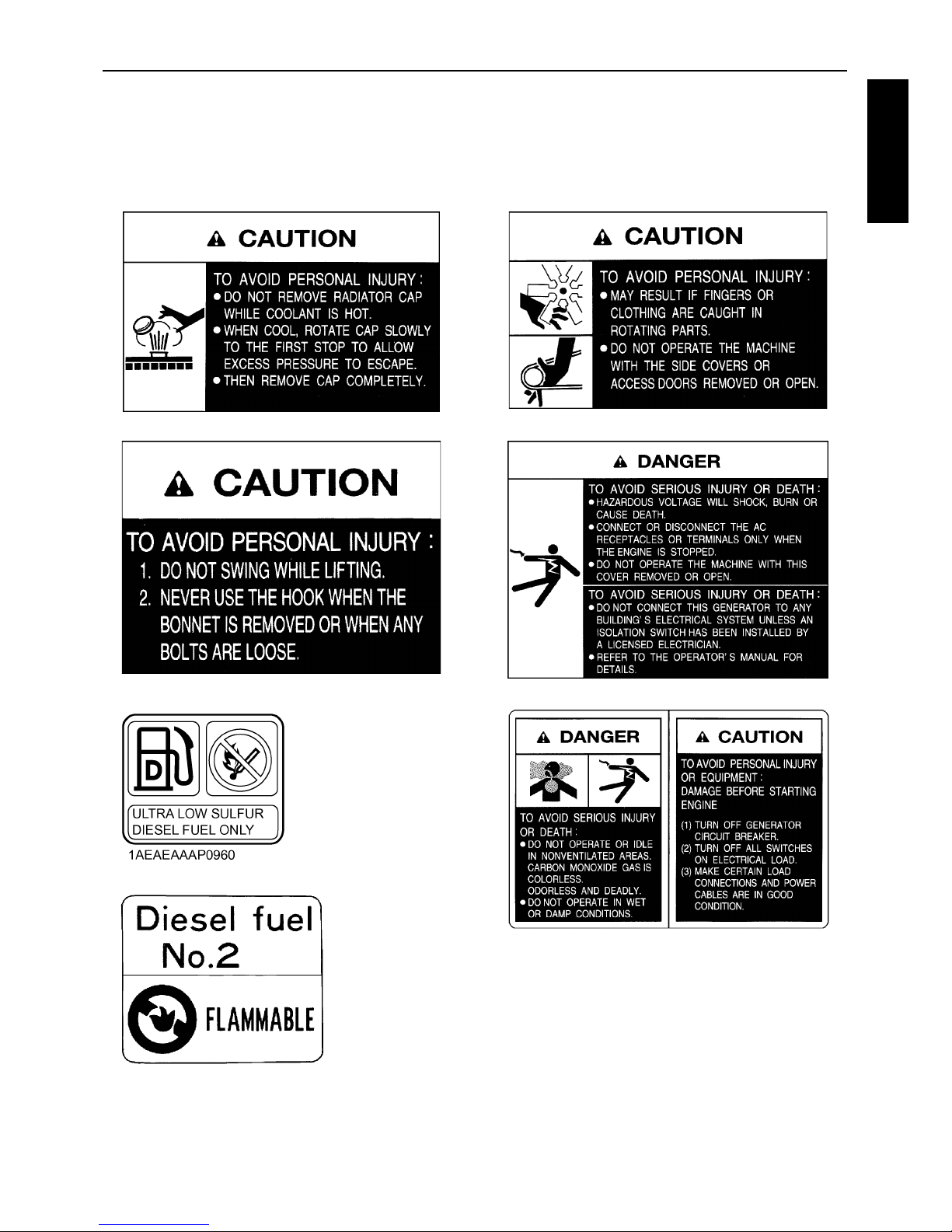
DANGER, WARNING AND CAUTION LABELS
Pay special attention to all labels on the generator.
Refer to following representations for labels used on the GL Series Generator. Labels are available individually from your KUBOTA Dealer.
(1) Part No. G3907-8832-0 (2) Part No. G3907-8830-0
(3) Part No. G3907-8836-0 (4) Part No. G3907-8831-0
(5) Part No. G3102-5090-2 (for USA)
(5) Part No. 18901-5090-2
(6) Part No. G3907-8824-0
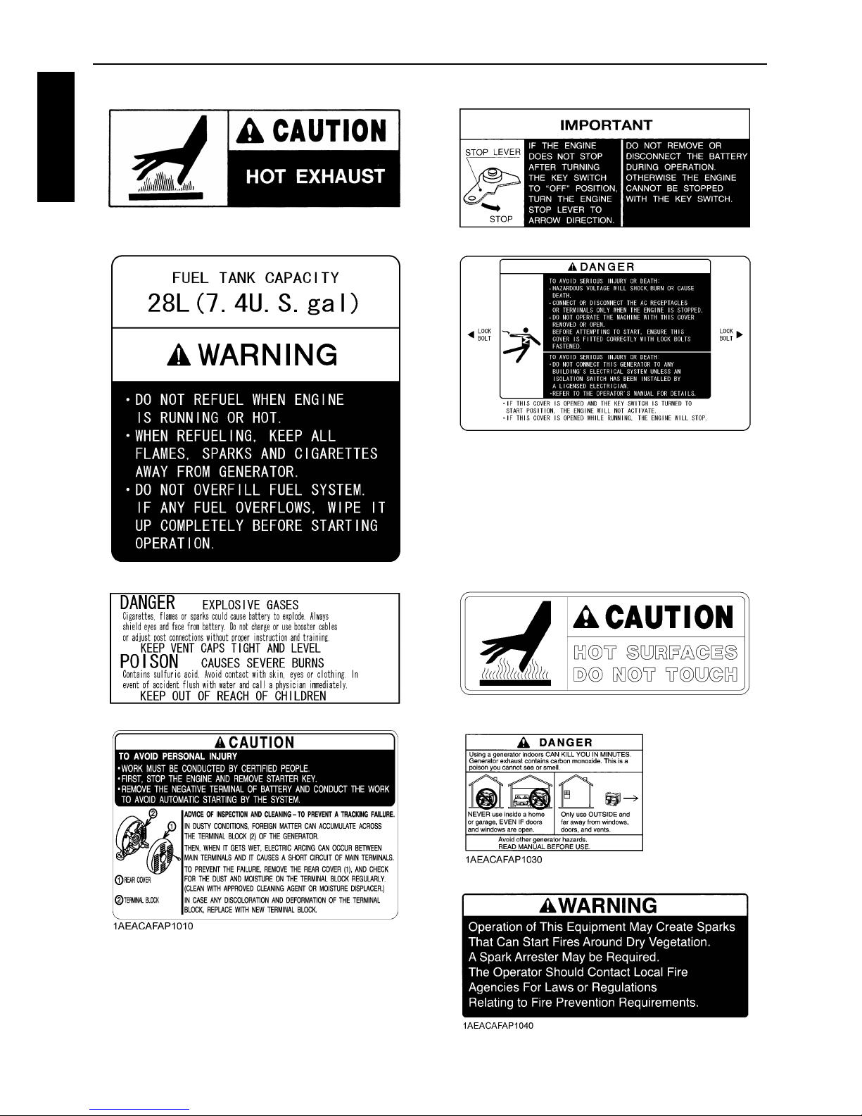
6 SAFETY PRECAUTIONS
ENGLISH
(7) Part No. 18620-8806-0 (8) Part No. G3907-8833-0
(9) Part No. G3102-8841-0 (10) Part No. G3101-8832-0
(11) Part No. 6C040-5559-0 (12) Part No. G3102-8806-0
(13) Part No. G3906-8831-0 (14) Part No. G3102-8838-0 (for U.S.A.)
(15) Part No. G3102-8839-0 (for U.S.A.)

7SAFETY PRECAUTIONS
ENGLISH
CARE OF DANGER, WARNING AND CAUTION LABELS
1. Keep danger, warning and caution labels clean and free from obstructing material.
2. Clean danger, warning and caution labels with soap and water, dry with a soft cloth.
3. Replace damaged or missing danger, warning and caution labels with new labels from your
local KUBOTA Dealer.
4. If a component with danger, warning and caution label(s) affixed is replaced with new part,
make sure new label(s) is (are) attached in the same location(s) as the replaced component.
5. Mount new danger, warning and caution labels by applying on a clean dry surface and
pressing any bubbles to outside edge.

1SERVICING OF GENERATOR
ENGLISH
SERVICING OF GENERATOR
Your dealer is interested in your new generator and has
the desire to help you get the most value from it. After
reading this manual thoroughly, you will find that you
can do some of the regular maintenance yourself.
However, when in need of parts or major service, be
sure to see your KUBOTA Dealer.
For service, contact the KUBOTA Dealership from
which you purchased your generator or your local
KUBOTA Dealer.
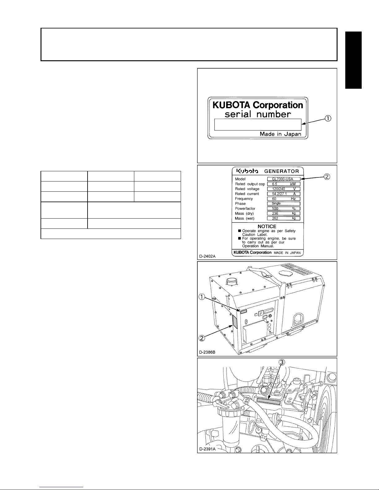
When in need of parts, be prepared to give your dealer
the generator and engine serial numbers.
Locate the serial numbers now and record them in the
space provided below.
model Serial No.
Generator
Engine
Date of
Purchase
Name of Dealer
(To be filled in by purchaser)
(1) Generator serial number
(2) Generator model
(3) Engine serial number
2 SPECIFICATION
ENGLISH
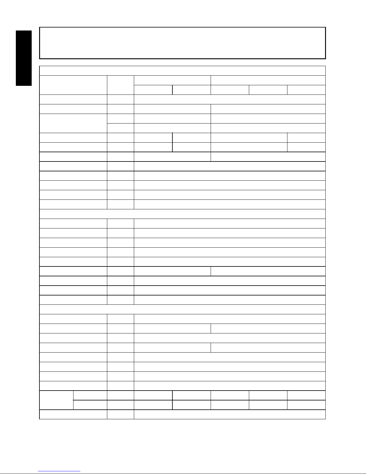
SPECIFICATION
GENERATOR
Model Unit
GL6000 GL7000
–STD –AUS –USA –USA-TM –STD
Design —
Salient-pole, revolving-field AC generator (AVR system with separate and self-excitation brush)
Frequency Hz 50 60
Rated Output (COP)
kVA 5.5 6.5
kW 5.5 6.5
Rated Voltage V 220 240 120/240 110/220
Rated amperage A 25 22.9 54.2/27.1 59.1/29.5
Phase & Wire ø-W 1-2 1-4
Power Factor % 100
No. of Poles — 2
Insulation — Rotor coil: Class F, Stator coil: Class B
Voltage Regulation % 5 (No load to full load)
Type of Coupling — Direct coupled
DIESEL ENGINE
Model — Z482
Design — Vertical, water-cooled, 4-cycle diesel engine
No. of cylinders — 2
Bore × stroke mm (in.) ø 67 × 68 (2.6 × 2.7)
Displacement L (cu. in.) 0.479 (29.2)
Engine speed rpm 3000 3600
Lubricating Oil — API service class CD or higher
Oil capacity
L (U.S.gal.)
2.2 (0.58)
Coolant capacity
L (U.S.gal.)
3.7 (0.98)
SET
Fuel — Diesel fuel No. 2 (ASTM D975)
Fuel consumption (at full load)
L (U.S.gal.)/h
2.4 (0.63) 2.7 (0.71)
Fuel tank capacity
L (U.S.gal.)
28 (7.4)
Continuous Operating Hours
hrs 12 10
Battery (V × Ah/5Hr) — 38B20R (12V × 28Ah)
Starting System — Electric
L × W × H mm (in.) 1066 × 618 × 698 (42.0 × 24.3 × 27.5)
Approx Net Wt. kg (lbs.) 235 (518)
Output
Terminal — { ——{{
Receptacle — {{{{{
Emergency Stop System — In case of abnormal : Oil pressure, water temperature
3SPECIFICATION
ENGLISH
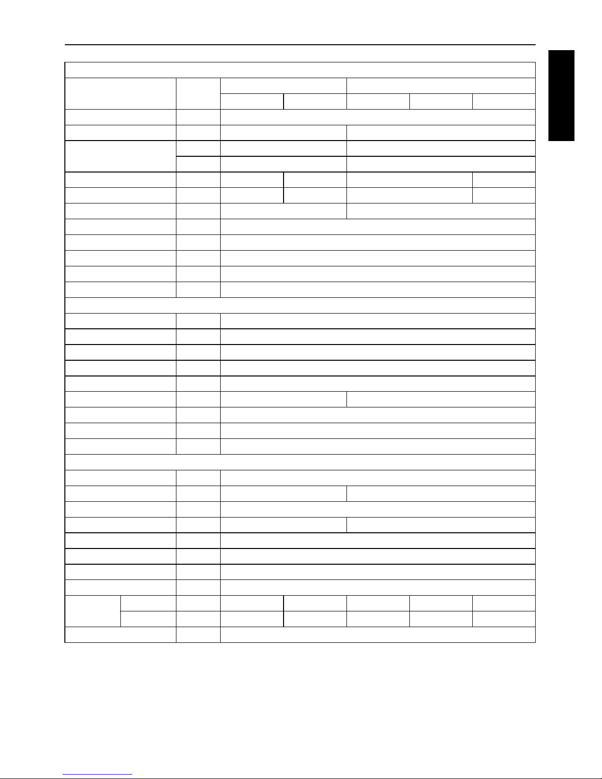
GENERATOR
Model Unit
GL9000 GL11000
–STD –AUS –USA –USA-TM –STD
Design —
Salient-pole, revolving-field AC generator (AVR system with separate and self-excitation brush)
Frequency Hz 50 60
Rated Output (COP)
kVA 8 10
kW 8 10
Rated Voltage V 220 240 120/240 110/220
Rated amperage A 36.4 33.3 83.3/41.7 90.9/45.5
Phase & Wire ø-W 1-2 1-3
Power Factor % 100
No. of Poles — 2
Insulation — Rotor coil: Class F, Stator coil: Class B
Voltage Regulation % 5 (No load to full load)
Type of Coupling — Direct coupled
DIESEL ENGINE
Model — D722
Design — Vertical, water-cooled, 4-cycle diesel engine
No. of cylinders — 3
Bore × stroke mm (in.) ø 67 × 68 (2.6 × 2.7)
Displacement L (cu. in.) 0.719 (43.9)
Engine speed rpm 3000 3600
Lubricating Oil — API service class CD or higher
Oil capacity
L (U.S.gal.)
3.4 (0.90)
Coolant capacity
L (U.S.gal.)
4.1 (1.1)
SET
Fuel — Diesel fuel No. 2 (ASTM D975)
Fuel consumption (at full load)
L (U.S.gal.)/h
3.3 (0.87) 4.1 (1.08)
Fuel tank capacity
L (U.S.gal.)
28 (7.4)
Continuous Operating Hours
hrs 8.5 7.0
Battery (V × Ah/5Hr) — 55B24R (12V × 36Ah)
Starting System — Electric
L × W × H mm (in.) 1281 × 618 × 698 (50.4 × 24.3 × 27.5)
Approx Net Wt. kg (lbs.) 295 (650)
Output
Terminal — { ——{{
Receptacle — {{{{{
Emergency Stop System — In case of abnormal : Oil pressure, water temperature
4 NOMENCLATURE
ENGLISH
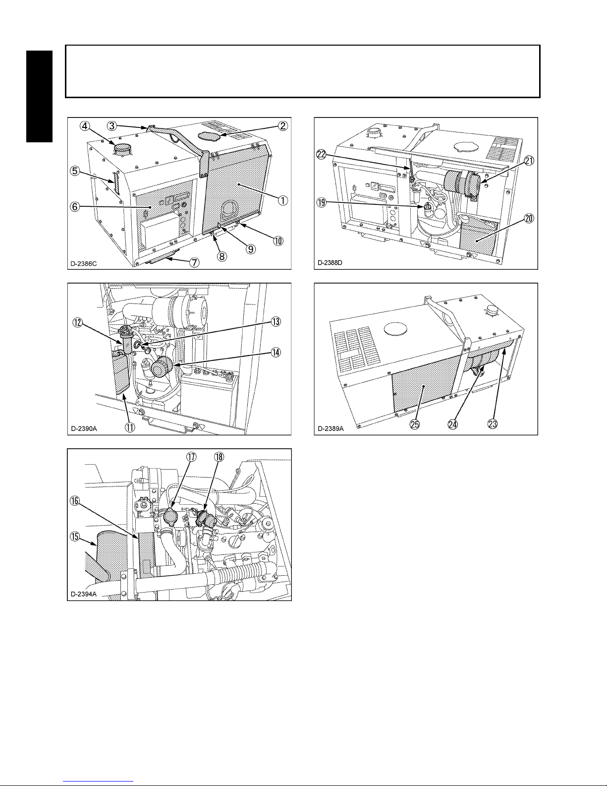
NOMENCLATURE
(1) Door
(2) Coolant filling port
(3) Hook
(4) Fuel tank cap
(5) Fuel gauge
(6) Control panel
(7) Base
(8) Engine oil drain plug
(9) Door lock
(10) Coolant drain plug
(11) Reserve tank
(12) Fuel filter
(13) Oil dipstick
(14) Oil filter cartridge
(15) Muffler
(16) Radiator
(17) Radiator cap
(18) Solenoid
(19) Engine oil port
(20) Battery
(21) Air cleaner
(22) Door stopper
(23) Fuel tank
(24) Alternator
(25) Safety shield
5NOMENCLATURE
ENGLISH
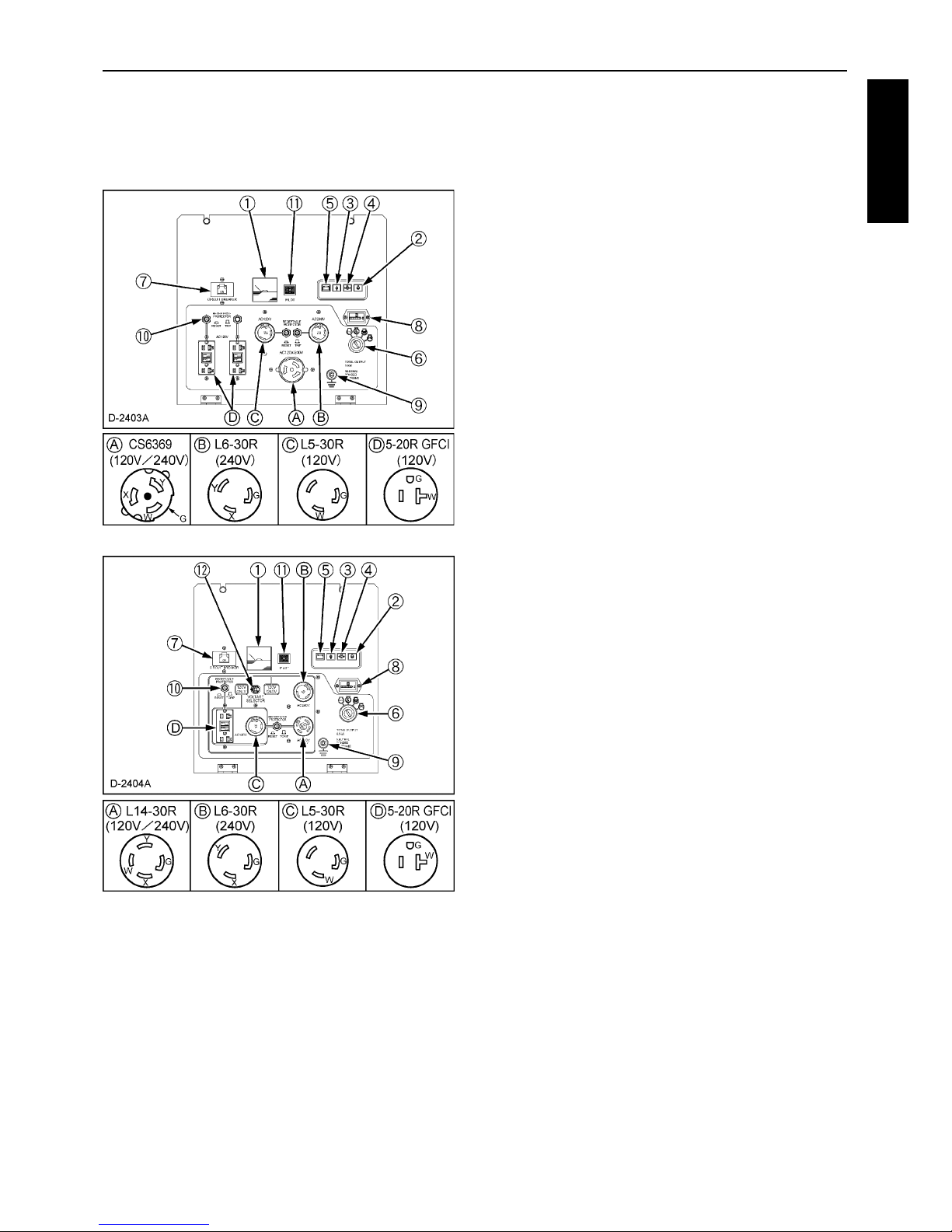
B Control Panel
Standard Model
C 1 Phase Type
(120/240V Dual voltage Type)
[GL11000-USA]
[GL7000-USA]
(1) A.C. Voltmeter
(2) Glow timer lamp
(3) Water temperature lamp
(4) Oil pressure lamp
(5) Battery charge lamp
(6) Starter switch (key)
(7) Circuit breaker
(8) Hour meter
(9) Ground terminal
(10) Protector (Receptacle)
(11) Pilot lamp
(12) Full power switch
(A) Receptacle
(B) Receptacle
(C) Receptacle
(D) Receptacle
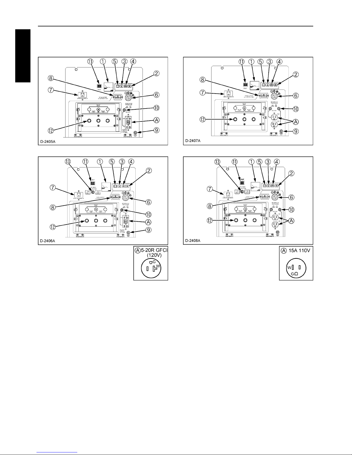
6 NOMENCLATURE
ENGLISH
C 1 Phase Type
(120V/240V Dual voltage type)
[GL11000-USA-TM]
[GL7000-USA-TM]
C 1 Phase Type
(110V/220V Dual voltage type)
[GL11000-STD]
[GL7000-STD]
(1) A.C. Voltmeter
(2) Glow timer lamp
(3) Water temperature lamp
(4) Oil pressure lamp
(5) Battery charge lamp
(6) Starter switch (key)
(7) Circuit breaker
(8) Hour meter
(9) Ground terminal
(10) Protector (Receptacle)
(11) Pilot lamp
(12) Terminals (Output)
(13) Full power switch
(A) Receptacle
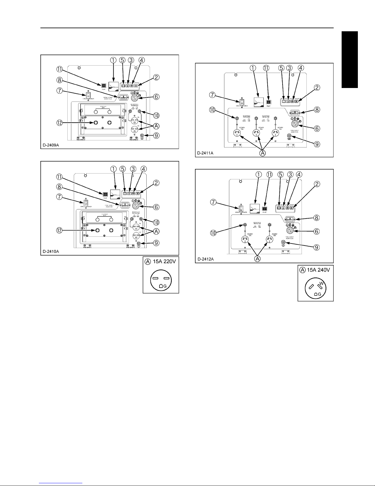
7NOMENCLATURE
ENGLISH
C 1 Phase Type (220V Type)
[GL9000-STD]
[GL6000-STD]
AUS Model
C 1 Phase Type (240V Type)
[GL9000-AUS]
[GL6000-AUS]
(1) A.C. Voltmeter
(2) Glow timer lamp
(3) Water temperature lamp
(4) Oil pressure lamp
(5) Battery charge lamp
(6) Starter switch (key)
(7) Circuit breaker
(8) Hour meter
(9) Ground terminal
(10) Protector (Receptacle)
(11) Pilot lamp
(12) Terminals (Output)
(A) Receptacle
(1) A.C. Voltmeter
(2) Glow timer lamp
(3) Water temperature lamp
(4) Oil pressure lamp
(5) Battery charge lamp
(6) Starter switch (key)
(7) Circuit breaker
(8) Hour meter
(9) Ground terminal
(10) Protector (Receptacle)
(11) Pilot lamp
(A) Receptacles
 Loading...