

Kubota GL6000, GL7000, GL9000, GL11000 Workshop Manual

WORKSHOP MANUAL
KiSC issued 05, 2015 A
DIESEL GENERATOR
GL6000,GL7000,
GL9000,GL11000

TO THE READER
KiSC issued 05, 2015 A
This Workshop Manual has been prepared to provide servicing personnel with
information on the mechanism, service and maintenance of KUBOTA Generator GL
Series. It is divided into three parts, “General”, “Mechanism” and “Servicing”.
General
Information on the general precautions, check and maintenance and special tools.
Mechanism
Information on the construction and function are included. This part should be
understood before proceeding with troubleshooting, disassembling and servicing.
Servicing
There are troubleshooting, servicing specification lists, checking and adjusting,
disassembling and assembling, and servicing which cover procedures, precautions,
factory specifications and allowable limits.
All information illustrations and specifications contained in this manual are based on
the latest product information available at the time of publication.
The right is reserved to make changes in all information at any time without notice.
© KUBOTA Corporation 2004
June 2004

Record of Revisions
KiSC issued 05, 2015 A
For pdf, use search function {Search word} to find all the revised locations.
Last digit
of the
Code No.
Issue
month
Main Revised Point and Corrective Measures {Search word}
3 2015.04 GL9000 / GL11000 Generator changed.
Reference
Page
GL6000, GL7000, GL9000, GL11000, WSM
SAFETY FIRST
KiSC issued 05, 2015 A
SAFETY INSTRUCTIONS
SAFETY INSTRUCTIONS
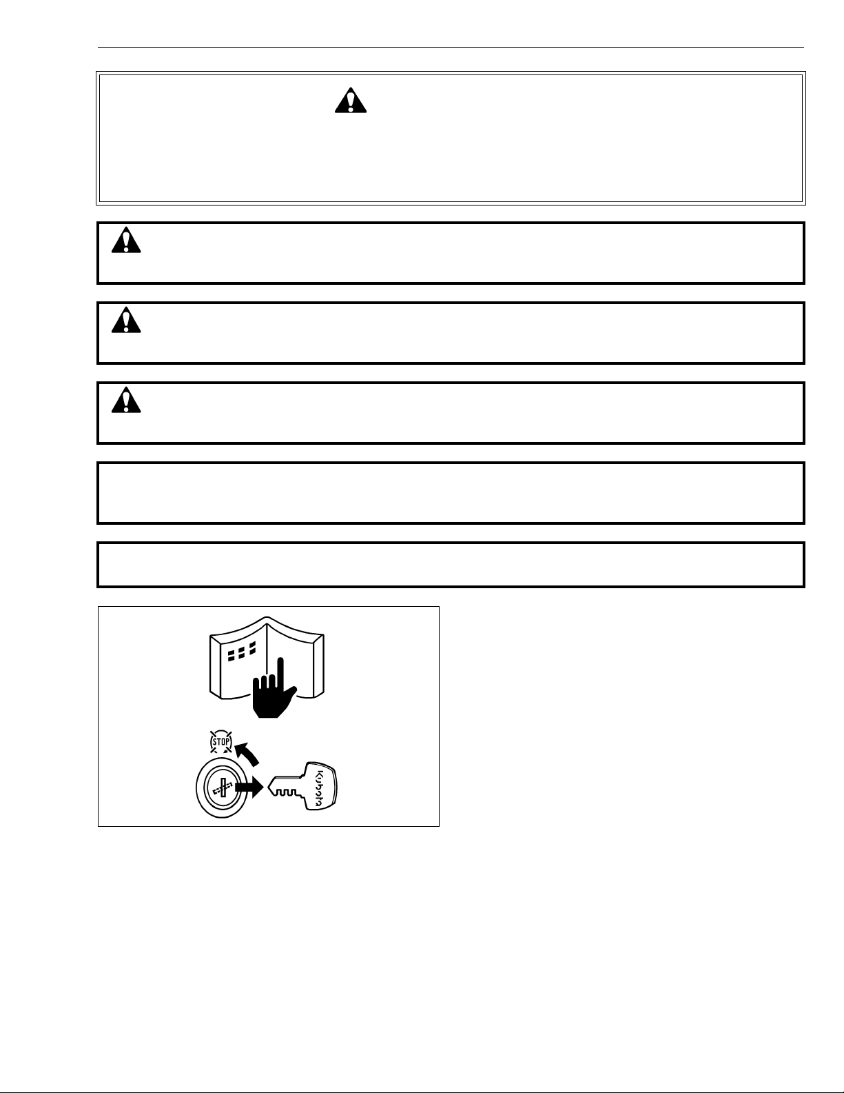
This symbol, the industry’s “Safety Alert Symbol”, is used throughout this manual and on labels on
the machine itself to warn of the possibility of personal injury. Read these instructions carefully.
It is essential that you read the instructions and safety regulations before you attempt to repair or use
this unit.
DANGER : Indicates an imminently hazardous situation which, if not avoided, will result in
death or serious injury.
WARNING : Indicates a potentially hazardous situation which, if not avoided, could result in
death or serious injury.
CAUTION : Indicates a potentially hazardous situation which, if not avoided, may result in
minor or moderate injury.
IMPORTANT : Indicates that equipment or property damage could result if instructions are not
followed.
NOTE : Gives helpful information.
BEFORE SERVICING AND REPAIRING
• Read all instructions and safety instructions in this
manual and on your generator safety decals.
• Clean the work area and generator.
• Park the generator on a firm and level ground.
• Allow the engine to cool before proceeding.
• Stop the engine, and remove the key.
• Disconnect the battery negative cable.
1
GL6000, GL7000, GL9000, GL11000, WSM
KiSC issued 05, 2015 A
SAFETY INSTRUCTIONS
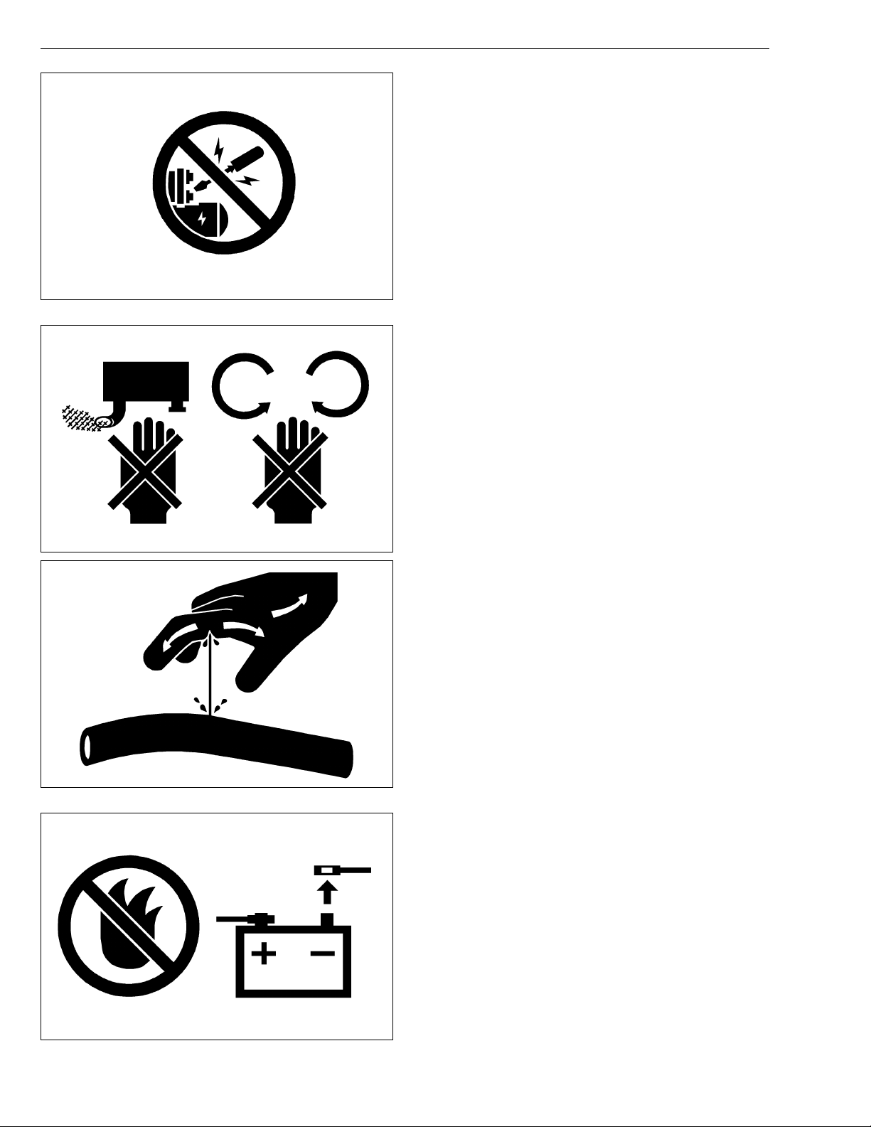
SAFETY STARTING
• Do not start the engine by shorting across starter
terminals or bypassing the safety start switch.
• Unauthorized modifications to the engine may impair
the function and / or safety and affect engine life.
SAFETY WORKING
• Do not work on the generator while under the
influence of alcohol, medication, or other substances
or while fatigued.
• Wear close fitting clothing and safety equipment
appropriate to the job.
• Use tools appropriate to the work. Makeshift tools,
parts, and procedures are not recommended.
• When servicing is performed together by two or more
persons, take care to perform all work safely.
• Do not touch the rotating or hot parts while the engine
is running.
• Never remove the radiator cap while the engine is
running, or immediately after stopping. Otherwise, hot
water will spout out from radiator. Only remove
radiator cap when cool enough to touch with bare
hands. Slowly loosen the cap to first stop to relieve
pressure before removing completely.
• Escaping fluid (fuel or hydraulic oil) under pressure
can penetrate the skin causing serious injury. Relieve
pressure before disconnecting hydraulic or fuel lines.
Tighten all connections before applying pressure.
• Wear a suitable hearing protective device such as
earmuffs or earplugs to protect against objectionable
or uncomfortable loud noises.
AVOID FIRES
• Fuel is extremely flammable and explosive under
certain conditions. Do not smoke or allow flames or
sparks in your working area.
• To avoid sparks from an accidental short circuit,
always disconnect the battery negative cable first and
connect it last.
• Battery gas can explode. Keep sparks and open
flame away from the top of battery, especially when
charging the battery.
• Make sure that no fuel has been spilled on the engine.
2
GL6000, GL7000, GL9000, GL11000, WSM
KiSC issued 05, 2015 A
SAFETY INSTRUCTIONS
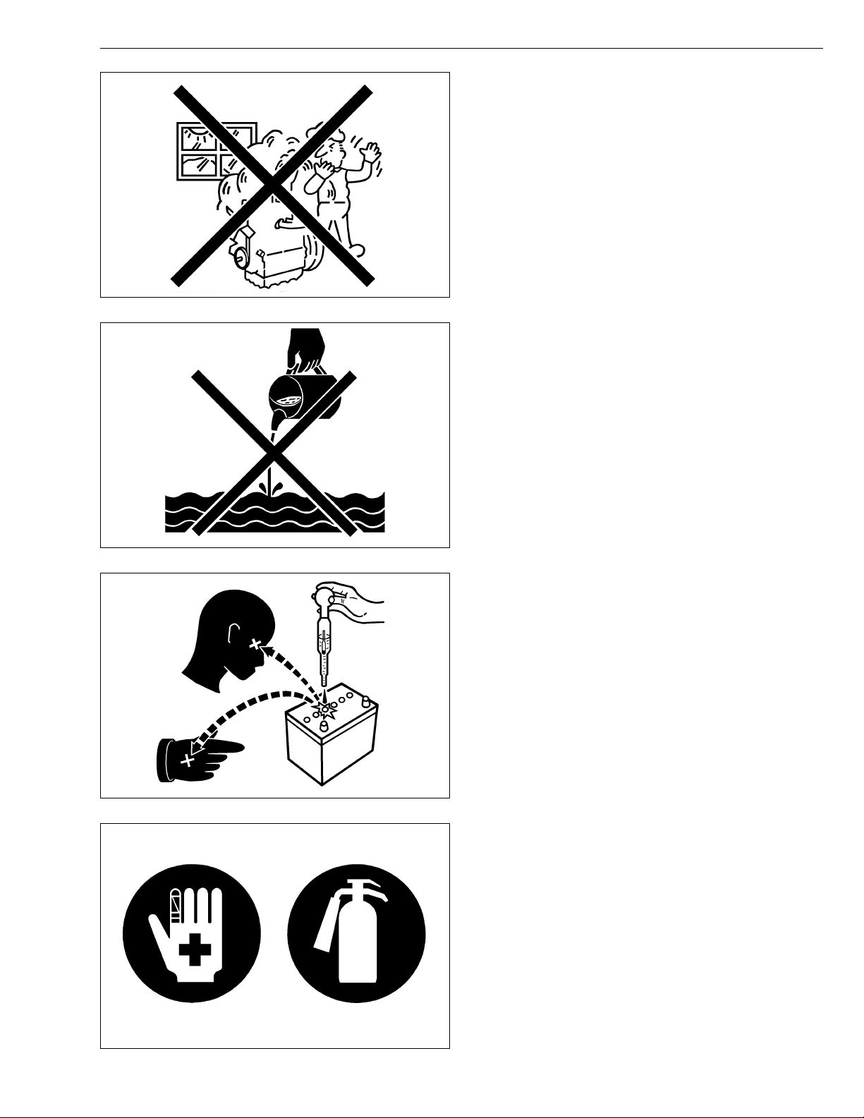
VENTILATE WORK AREA
• If the engine must be running to do some work, make
sure the area is well ventilated. Never run the engine
in a closed area. The exhaust gas contains poisonous
carbon monoxide.
DISPOSE OF FLUIDS PROPERLY
• Do not pour fluids into the ground, down a drain, or
into a stream, pond, or lake. Observe relevant
environmental protection regulations when disposing
of oil, fuel, coolant, electrolyte and other harmful
waste.
PREVENT ACID BURNS
• Sulfuric acid in battery electrolyte is poisonous. It is
strong enough to burn skin, clothing and cause
blindness if splashed into eyes. Keep electrolyte
away from eyes, hands and clothing. If you spill
electrolyte on yourself, flush with water, and get
medical attention immediately.
PREPARE FOR EMERGENCIES
• Keep a first aid kit and fire extinguisher handy at all
times.
• Keep emergency numbers for doctors, ambulance
service, hospital and fire department near your
telephone.
3
GL6000, GL7000, GL9000, GL11000, WSM
KiSC issued 05, 2015 A
SAFETY INSTRUCTIONS
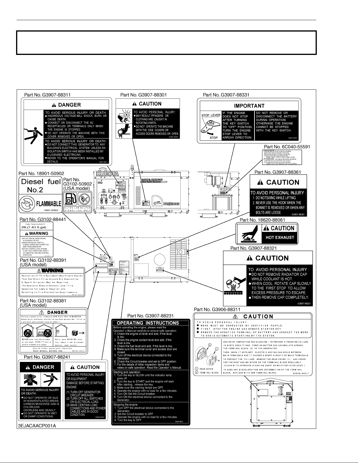
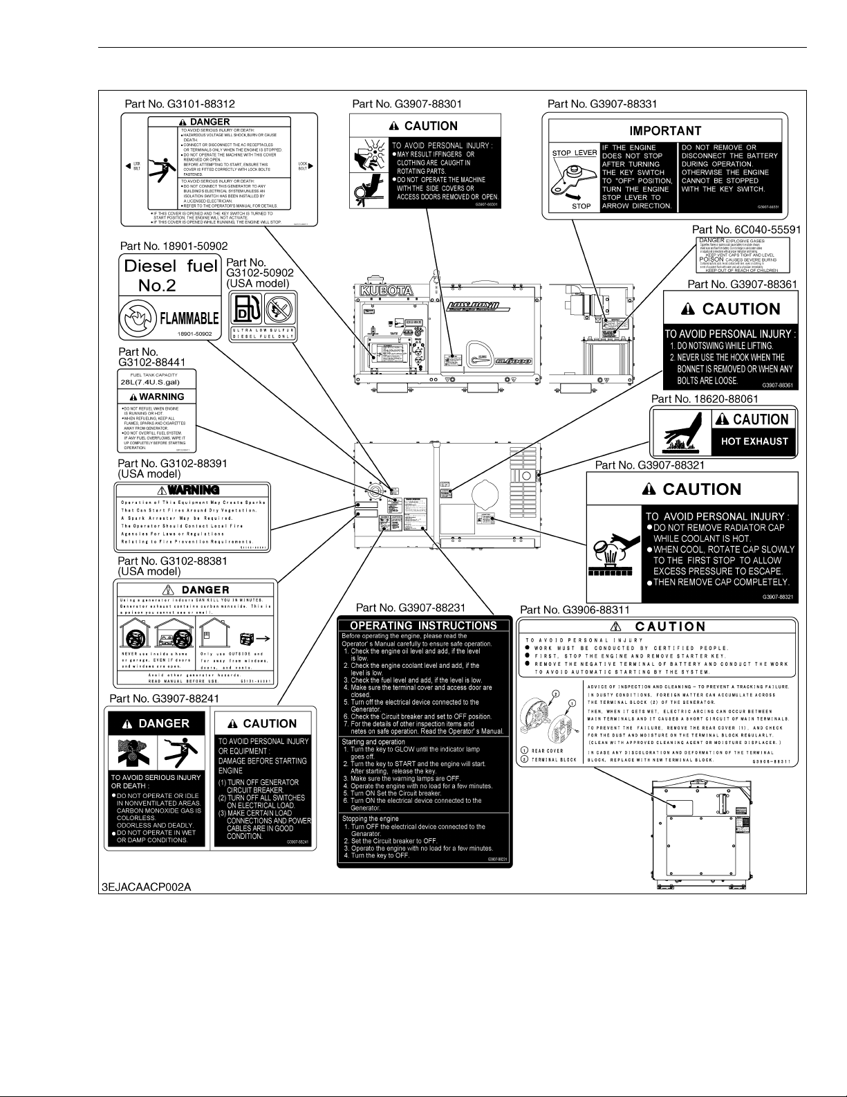
SAFETY DECALS
The following safety decals are installed on the generator.
If a decal becomes damaged, illegible or is not on the generator, replace it. The decal part number is listed
in the parts list.
[Receptacle Type]
4
GL6000, GL7000, GL9000, GL11000, WSM
KiSC issued 05, 2015 A
[Terminal Type]
SAFETY INSTRUCTIONS
5
GL6000, GL7000, GL9000, GL11000, WSM
KiSC issued 05, 2015 A
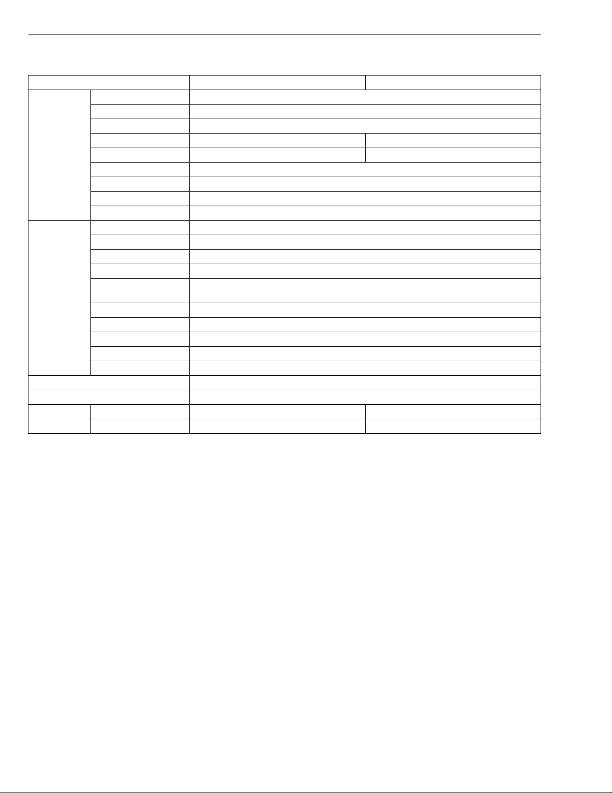
SPECIFICATIONS
Model GL6000-STD GL6000-AUS
Frequency 50 Hz
Rated output 5.5 kW
Maximum output 6.0 kW
Rated voltage 220 V 240 V
Generator
Engine
Continuous operating hours (at rated load) 12 hrs
Net weight kg (lbs) 235 kg (518 lbs)
Output
* Conversion Formula : HP = 0.746 kW, PS = 0.7355 kW
Rated current 25 A 22.9 A
Phrase and wire 1 - 2
Number of poles 2
Power Factor 1
Insulation Stator coil: B Rotor coil: F
Design Vertical, liquid cooled, 4 cycle, diesel
Model name Z482-E2B-SEC-2
Rated output 6.9 kW
Speed 3000 min
Number of cylinder Bore x Stroke
Displacement 0.479 L (29.23 cu.in.)
Fuel tank capacity 28 L (7.4 U.S.gals)
Crankcase oil capacity 2.2 L (0.58 U.S.gals)
Starting system Electric type 12 V / 0.8 kW
Battery 38B20R 12 V x 28 Ah / 5 Hr
Receptacle 6-15R 2 15A 2
Te rm i n al 2 P –
2 - 67 x 68 mm (2 - 2.52 x 2.68 in.)
-1
SPECIFICATIONS
(rpm)
W1028103
6
GL6000, GL7000, GL9000, GL11000, WSM
KiSC issued 05, 2015 A
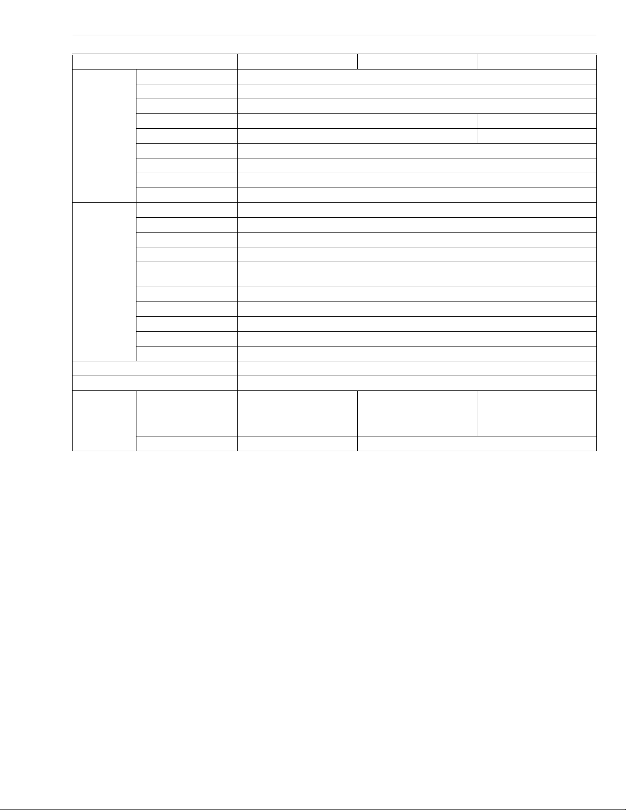
Model GL7000-USA GL7000-USA-TM GL7000-STD
Frequency 60 Hz
Rated output 6.5 kW
Maximum output 7.0 kW
Rated voltage 120 / 240 V 110 / 220 V
Generator
Engine
Continuous operating hours (at rated load) 10 hrs
Net weight kg (lbs) 235 kg (518 lbs)
Output
* Conversion Formula : HP = 0.746 kW, PS = 0.7355 kW
Rated current 54.2 / 27.1 A 59.1 / 29.5 A
Phrase and wire 1 - 4
Number of poles 2
Power Factor 1
Insulation Stator coil: B Rotor coil: F
Design Vertical, liquid cooled, 4 cycle, diesel
Model name Z482-E2B-SEC-3
Rated output 8.1 kW
Speed 3600 min
Number of cylinder Bore x Stroke
Displacement 0.479 L (29.23 cu.in.)
Fuel tank capacity 28 L (7.4 U.S.gals)
Crankcase oil capacity 2.2 L (0.58 U.S.gals)
Starting system Electric type 12 V / 0.8 kW
Battery 38B20R 12 V x 28 Ah / 5 Hr
Receptacle L14-30R
L6-30R
L5-30R
5-20RA (GFCI)
Terminal – 3P
2 - 67 x 68 mm (2 - 2.52 x 2.68 in.)
-1
(rpm)
5-20RA (GFCI) 5-15R x 2
SPECIFICATIONS
W1030469
7
GL6000, GL7000, GL9000, GL11000, WSM
KiSC issued 05, 2015 A
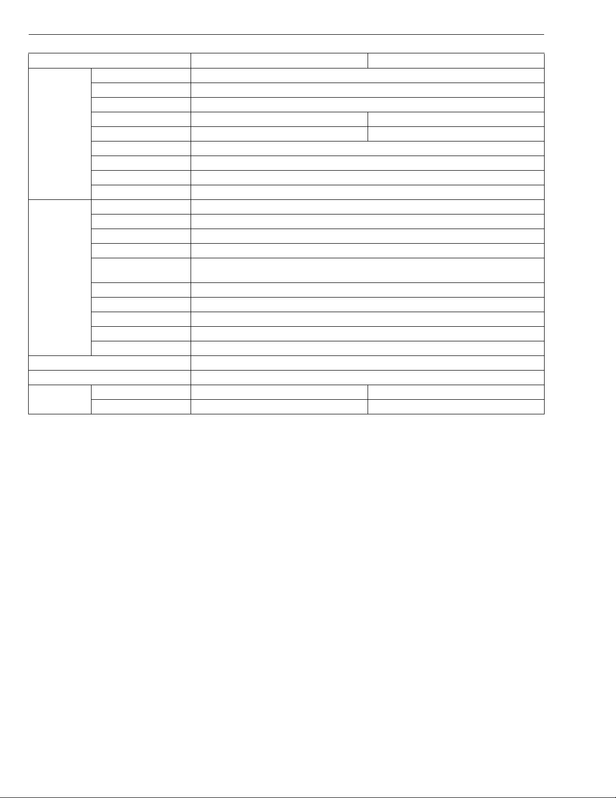
Model GL9000-STD GL9000-AUS
Frequency 50 Hz
Rated output 8.0 kW
Maximum output 8.8 kW
Rated voltage 220 V 240 V
Generator
Engine
Continuous operating hours (at rated load) 8.5 hrs
Net weight kg (lbs) 280 kg (617 lbs)
Output
* Conversion Formula : HP = 0.746 kW, PS = 0.7355 kW
Rated current 36.4 A 33.3 A
Phrase and wire 1 - 2
Number of poles 2
Power Factor 1
Insulation Stator coil: B Rotor coil: F
Design Vertical, liquid cooled, 4 cycle, diesel
Model name D722-E2B-SEC-2
Rated output 10.3 kW
Speed 3000 min
Number of cylinder Bore x Stroke
Displacement 0.719 L (48.89 cu.in.)
Fuel tank capacity 28 L (7.4 U.S.gals)
Crankcase oil capacity 3.4 L (0.90 U.S.gals)
Starting system Electric type 12 V / 1.0 kW
Battery 55B24R 12 V x 36 Ah / 5 Hr
Receptacle 6-15R 2 15A 3
Te rm i n al 2 P –
3 - 67 x 68 mm (3 - 2.52 x 2.68 in.)
-1
SPECIFICATIONS
(rpm)
W1030823
8
GL6000, GL7000, GL9000, GL11000, WSM
KiSC issued 05, 2015 A
Model GL11000-USA GL11000-USA-TM GL11000-STD
Frequency 60 Hz
Rated output 10.0 kW
Maximum output 11.0 kW
Rated voltage 120 / 240 V 110 / 220 V
Generator
Engine
Continuous operating hours (at rated load) 7 hrs
Net weight kg (lbs) 280 kg (617 lbs)
Output
* Conversion Formula : HP = 0.746 kW, PS = 0.7355 kW
Rated current 83.3 / 41.7 A 90.9 / 45.5 A
Phrase and wire 1 - 3
Number of poles 2
Power Factor 1
Insulation Stator coil: B Rotor coil: F
Design Vertical, liquid cooled, 4 cycle, diesel
Model name D722-E2B-SEC-2
Rated output 12.2 kW
Speed 3600 min
Number of cylinder Bore x Stroke
Displacement 0.719 L (48.89 cu.in.)
Fuel tank capacity 28 L (7.4 U.S.gals)
Crankcase oil capacity 3.4 L (0.90 U.S.gals)
Starting system Electric type 12 V / 1.0 kW
Battery 55B24R 12 V x 36 Ah / 5 Hr
Receptacle CS6369 (50 A)
L6-30R
L5-30R
5-20R (GFCI) 2
3 - 67 x 68 mm (3 - 2.52 x 2.68 in.)
-1
(rpm)
5-20R (GFCI) 5-15R 2
SPECIFICATIONS
W1031698
9
GL6000, GL7000, GL9000, GL11000, WSM
KiSC issued 05, 2015 A
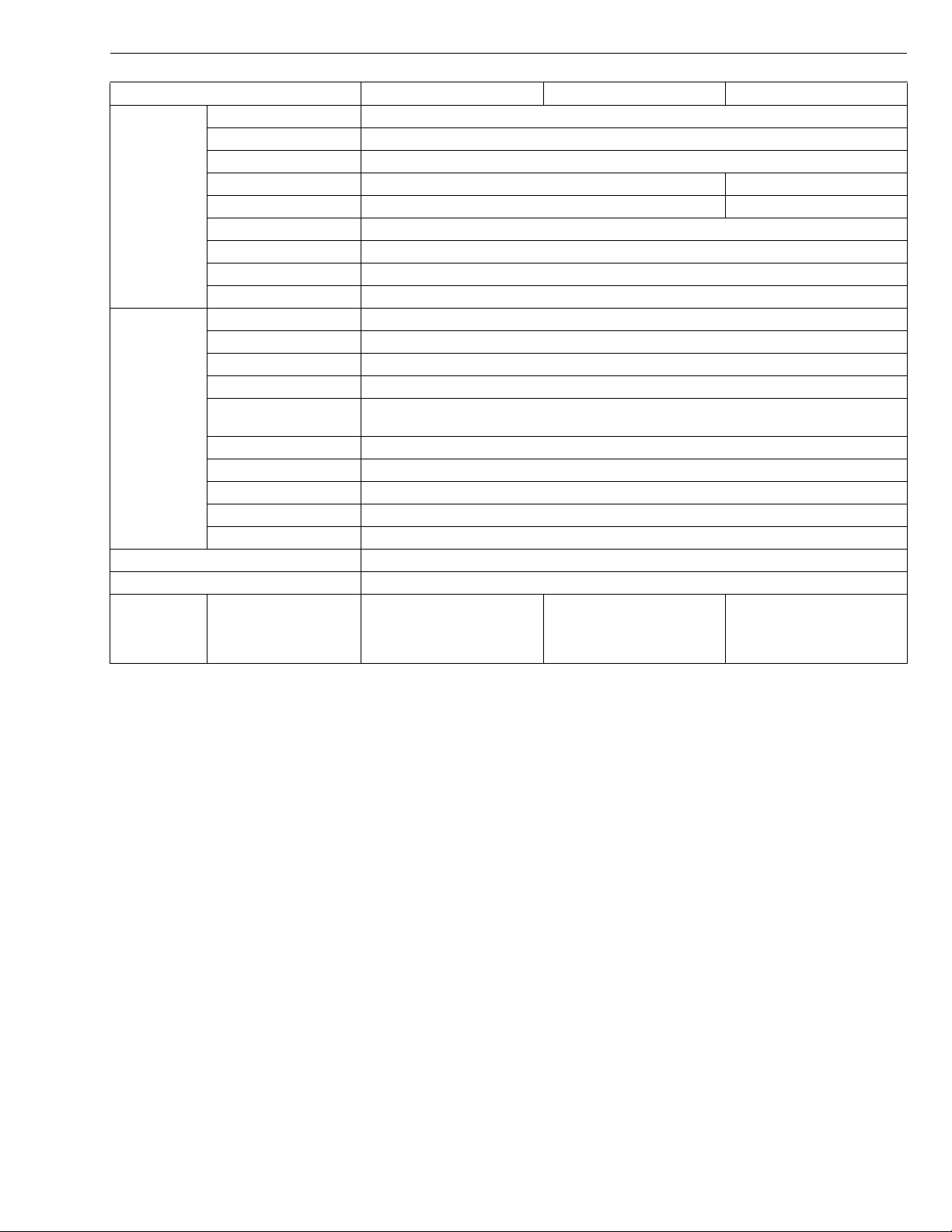
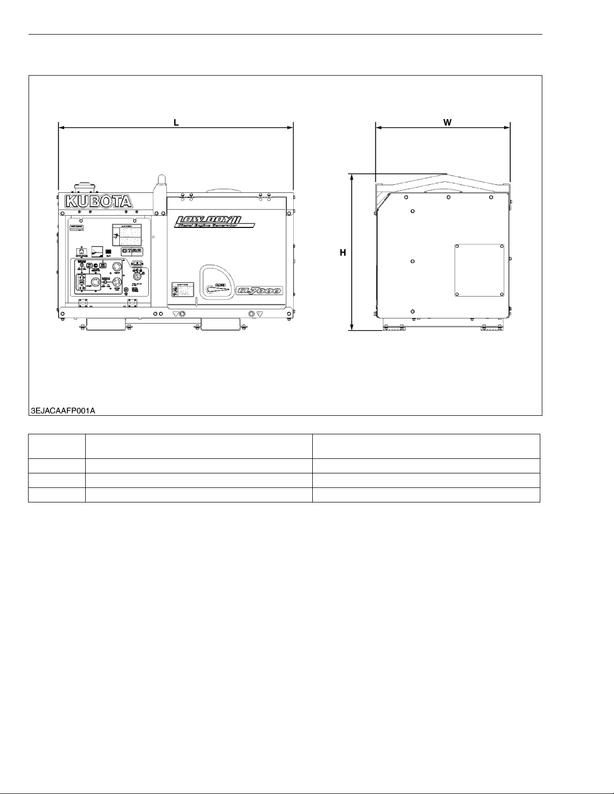
DIMENSIONS
DIMENSIONS
GL6000-STD, GL6000-AUS,
GL7000-STD, GL7000-USA, GL7000-USA-TM
L 1066 mm (42.0 in.) 1281 mm (50.4 in.)
W 618 mm (24.3 in.) 618 mm (24.3 in.)
H 698 mm (27.5 in.) 698 mm (27.5 in.)
GL9000-STD, GL9000-AUS, GL11000-STD,
GL11000-USA, GL11000-USA-TM
W1038971
10

GENERAL
KiSC issued 05, 2015 A
CONTENTS
1. IDENTIFICATION............................................................................................. G-1
[1] MODEL NAME AND ENGINE SERIAL NUMBER ................................ G-1
[2] E4B ENGINE............................................................................................. G-2
[3] CYLINDER NUMBER ............................................................................... G-3
2. PRECAUTION.................................................................................................. G-4
3. HANDLING PRECAUTIONS FOR ELECTRICAL PARTS AND WIRING .. G-5
[1] WIRING ..................................................................................................... G-5
[2] BATTERY................................................................................................... G-7
[3] FUSE.......................................................................................................... G-7
[4] CONNECTOR ............................................................................................ G-7
[5] HANDLING OF CIRCUIT TESTER ......................................................... G-8
4. LUBRICANTS, FUEL AND COOLANT ......................................................... G-9
5. TIGHTENING TORQUES ............................................................................. G-11
[1] GENERAL USE SCREWS, BOLT AND NUTS ................................... G-11
[2] STUD BOLTS.......................................................................................... G-11
6. MAINTENANCE CHECK LIST ..................................................................... G-12
7. CHECK AND MAINTENANCE ..................................................................... G-14
[1] DAILY CHECK ........................................................................................ G-14
[2] CHECK POINTS OF INITIAL 50 HOURS ........................................... G-15
[3] CHECK POINT OF EVERY 50 HOURS ............................................. G-16
[4] CHECK POINT OF EVERY 100 HOURS ........................................... G-16
[5] CHECK POINT OF EVERY 200 HOURS ........................................... G-18
[6] CHECK POINT OF EVERY 300 HOURS ........................................... G-19
[7] CHECK POINT OF EVERY 400 HOURS ........................................... G-19
[8] CHECK POINTS OF EVERY 500 HOURS......................................... G-20
[9] CHECK POINT OF EVERY 800 HOURS ........................................... G-22
[10]CHECK POINT OF EVERY 1000 HOURS ......................................... G-23
[11]CHECK POINT OF EVERY 1500 HOURS ......................................... G-23
[12]CHECK POINT OF EVERY 1 YEAR................................................... G-24
[13]CHECK POINT OF EVERY 2 YEARS ................................................ G-24
8. SPECIAL TOOLS.......................................................................................... G-26
GL6000, GL7000, GL9000, GL11000, WSM
KiSC issued 05, 2015 A
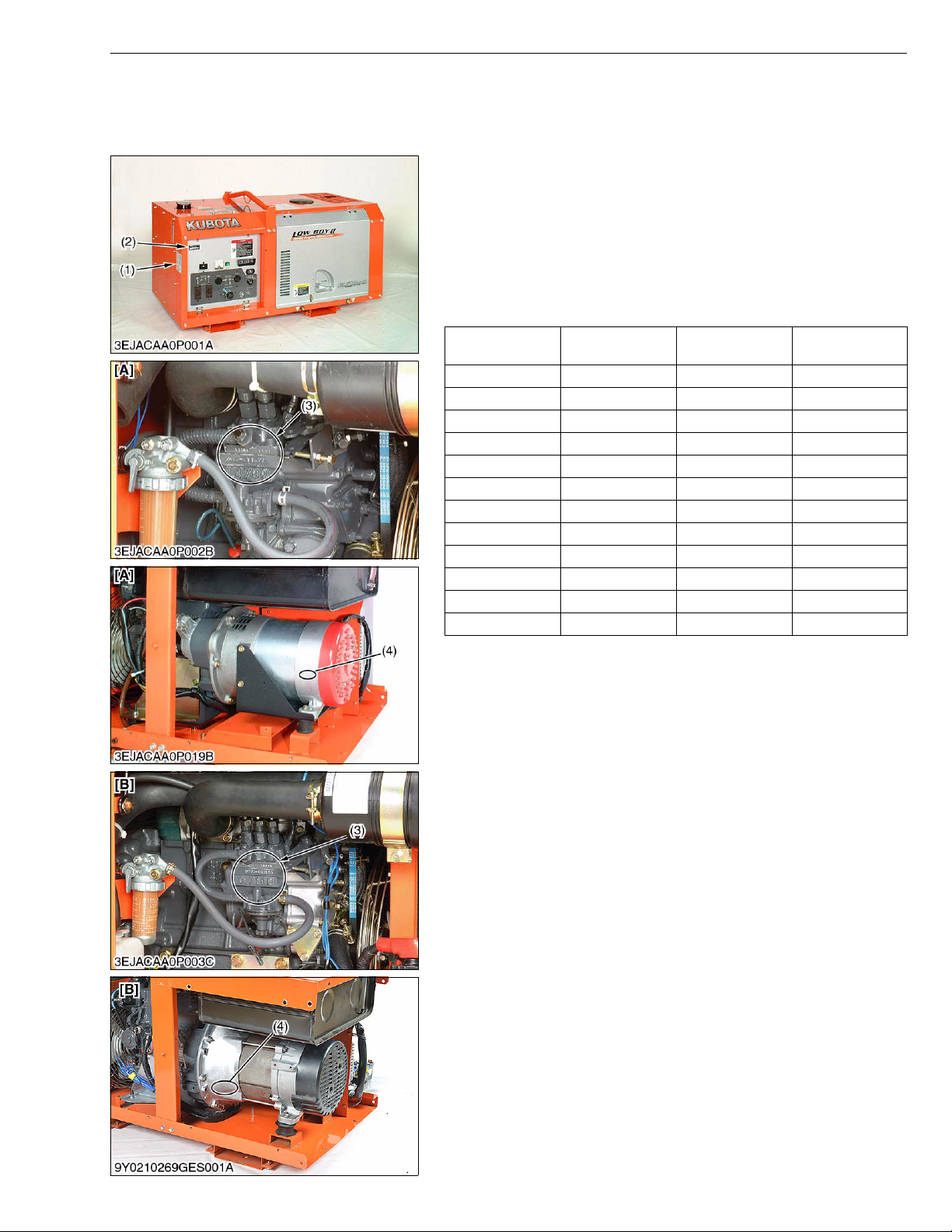
1. IDENTIFICATION
[1] MODEL NAME AND ENGINE SERIAL NUMBER
When contacting your local KUBOTA distributor, always specify
the model name and serial numbers of both engine and generator.
The engine model and its serial number need to be identified
before the engine can be serviced or parts replaced.
Engine Serial Number
The engine serial number is an identified number for the engine.
It is marked after the engine model number.
It indicates month and year of manufacture as follows.
• Year of manufacture
Alphabet or
Number
4 2004 G 2016
5 2005 H 2017
6 2006 J 2018
7 2007 K 2019
8 2008 L 2020
9 2009 M 2021
A 2010 N 2022
B 2011 P 2023
C 2012 R 2024
D 2013 S 2025
E 2014 T 2026
F 2015 V 2027
Year
Alphabet or
Number
G GENERAL
Yea r
(1) Model Name
(2) Serial Number
(3) Engine Model Name and Serial
Number
(4) Generator Model Name and Serial
Number
[A] GL6000, GL7000
[B] GL9000, GL11000
W1035676
G-1
GL6000, GL7000, GL9000, GL11000, WSM
KiSC issued 05, 2015 A
G GENERAL
• Month of manufacture
Month
January A0001 ~ A9999 B0001 ~
February C0001 ~ C9999 D0001 ~
March E0001 ~ E9999 F0001 ~
April G0001 ~ G9999 H0001 ~
May J0001 ~ J9999 K0001 ~
June L0001 ~ L9999 M0001 ~
July N0001 ~ N9999 P0001 ~
August Q0001 ~ Q9999 R0001 ~
September S0001 ~ S9999 T0001 ~
October U0001 ~ U9999 V0001 ~
November W0001 ~ W9999 X0001 ~
December Y0001 ~ Y9999 Z0001 ~
e.g. D722-5A0001
"5" indicates 2005 and "A" indicates January.
So, 5A indicates that the engine was manufactured in January, 2005.
0001 ~ 9999 10000 ~
Engine Serial Number
W1011076
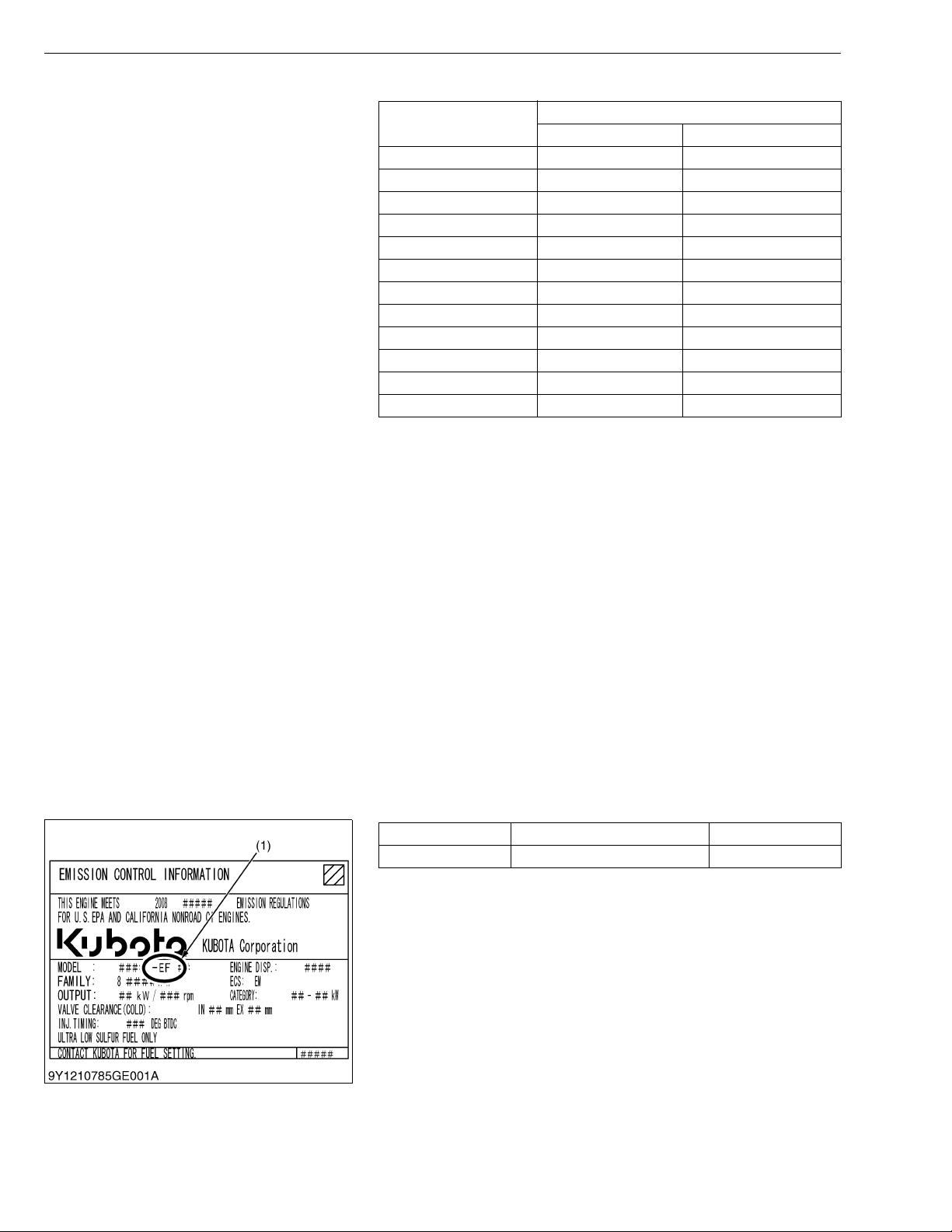
[2] E4B ENGINE
[Example : Engine Model Name D902-E4B-XXXX]
The emission controls previously implemented in various countries to prevent air pollution will be stepped up as
Non-Road Emission Standards continue to change. The timing or applicable date of the specific Non-Road Emission
regulations depends on the engine output classification.
Over the past several years, KUBOTA has been supplying diesel engines that comply with regulations in the
respective countries affected by Non-Road Emission regulations. For KUBOTA Engines, E4B will be the designation
that identifies engine models affected by the next emission phase (See the table below).
When servicing or repairing ###-E4B series engines, use only replacement parts for that specific E4B engine,
designated by the appropriate E4B KUBOTA Parts List and perform all maintenance services listed in the appropriate
KUBOTA Operator's Manual or in the appropriate E4B KUBOTA Workshop Manual. Use of incorrect replacement
parts or replacement parts from other emission level engines (for example: E2B engines), may result in emission
levels out of compliance with the original E4B design and EPA or other applicable regulations. Please refer to the
emission label located on the engine head cover to identify Output classification and Emission Control Information.
E4B engines are identified with "EF" at the end of the Model designation, on the US EPA label. Please note : E4B is
not marked on the engine.
Category (1) Engine output classification EPA regulation
EF Less than 19 kW Tier 4
(1) "E4B" engines are identified with "EF" at the end of the Model designation, on
the US EPA label.
"E4B" designates Tier 4, depending on engine output classification.
W1030236
G-2

GL6000, GL7000, GL9000, GL11000, WSM
KiSC issued 05, 2015 A
[3] CYLINDER NUMBER
G GENERAL
The cylinder numbers of KUBOTA diesel engine are designated
as shown in the figure.
The sequence of cylinder numbers is given as No.1, No.2 and
No.3 starting from the gear case side.
W1011077
G-3
GL6000, GL7000, GL9000, GL11000, WSM
KiSC issued 05, 2015 A
2. PRECAUTION
G GENERAL
• During disassembly, carefully arrange removed parts in a clean
area to prevent confusion later. Screws, bolts and nuts should be
replaced in their original position to prevent reassembly errors.
• When special tools are required, use KUBOTA genuine special
tools. Special tools which are not frequently used should be
made according to the drawings provided.
• Before disassembling or servicing live wires, make sure to
always disconnect the grounding cable from the battery first.
• Remove oil and dirt from parts before measuring.
• Use only KUBOTA genuine parts for parts replacement to
maintain engine performance and to ensure safety.
• Gaskets and O-rings must be replaced during reassembly. Apply
grease to new O-rings or oil seals before assembling.
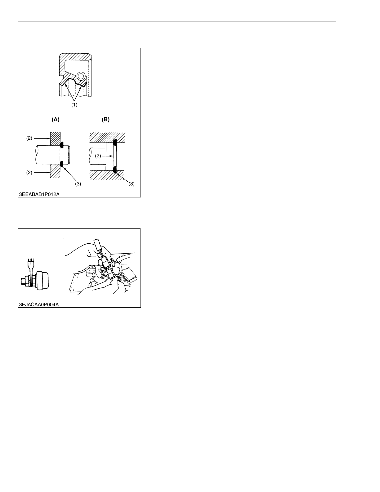
• When reassembling external or internal snap rings, position them
so that the sharp edge faces against the direction from which
force is applied.
• Be sure to perform run-in the serviced or reassembled engine.
Do not attempt to give heavy load at once, or serious damage
may result to the engine.
(1) Grease
(2) Force
(3) Place the Sharp Edge against the
Direction of Force
(A) External Snap Ring
(B) Internal Snap Ring
W10109040
• Before checking any generator or engine electrical component,
be sure to check that all terminals and connectors are tight.
• After the individual component inspection, also inspect the wire
leads for continuity; that might be the cause of the problem.
• The rotor and stator must be protected when disassembling and
reassembling.
If they are damaged, no power can be generated.
• To maintain the generator's performance and ensure safety, use
only KUBOTA genuine parts for replacement.
• Use extreme caution when working on electrical components.
Electrical shocks cause injury or death.
W10262580
G-4
GL6000, GL7000, GL9000, GL11000, WSM
IMPORTANT
KiSC issued 05, 2015 A
G GENERAL
3. HANDLING PRECAUTIONS FOR ELECTRICAL PARTS
AND WIRING
To ensure safety and prevent damage to the machine and
surrounding equipment, heed the following precautions in handling
electrical parts and wiring.
• Check electrical wiring for damage and loosened
connection every year. To this end, educate the customer to
do his or her own check and at the same time recommend
the dealer to perform periodic check for a fee.
• Do not attempt to modify or remodel any electrical parts and
wiring.
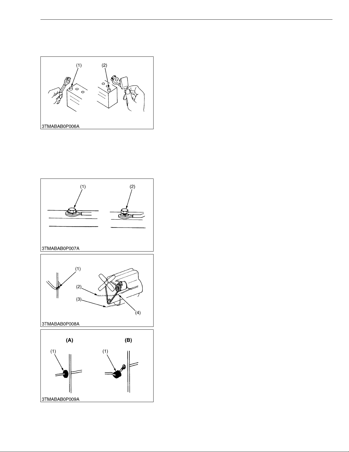
• When removing the battery cables, disconnect the negative
cable first. When installing the battery cables, connect the
positive cable first.
(1) Negative Terminal (2) Positive Terminal
W10111140
[1] WIRING
• Securely tighten wiring terminals.
(1) Correct
(Securely Tighten)
(2) Incorrect
(Loosening Leads to Faulty Contact)
W10112160
• Do not let wiring contact dangerous part.
(1) Dangerous Part
(2) Wiring (Incorrect)
(3) Wiring (Correct)
(4) Dangerous Part
• Securely insert grommet.
(1) Grommet (A) Correct
(B) Incorrect
W10113130
W10113880
G-5
GL6000, GL7000, GL9000, GL11000, WSM
KiSC issued 05, 2015 A
G GENERAL
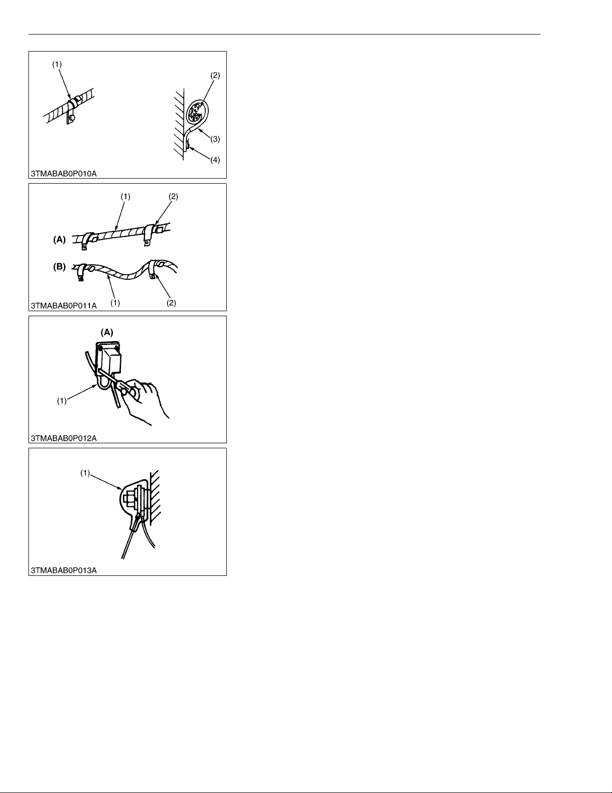
• Securely clamp, being careful not to damage wiring.
(1) Clamp
• Wind Clamp Spirally
(2) Wire Harness
(3) Clamp
(4) Welding Dent
W10114580
• Clamp wiring so that there is no twist, unnecessary sag, or
excessive tension, except for movable part, where sag be
required.
(1) Wiring
(2) Clamp
(A) Correct
(B) Incorrect
W10115870
• In installing a part, take care not to get wiring caught by it.
(1) Wiring (A) Incorrect
W10116700
• After installing wiring, check protection of terminals and clamped
condition of wiring, only connect battery.
(1) Cover
• Securely Install Cover
W10117350
G-6
GL6000, GL7000, GL9000, GL11000, WSM
CAUTION
KiSC issued 05, 2015 A
[2] BATTERY
G GENERAL
• Take care not to confuse positive and negative terminal posts.
• When removing battery cables, disconnect negative cable first.
When installing battery cables, check for polarity and connect
positive cable first.
• Do not install any battery with capacity other than is specified
(Ah).
• After connecting cables to battery terminal posts, apply high
temperature grease to them and securely install terminal covers
on them.
• Do not allow dirt and dust to collect on battery.
• Take care not to let battery liquid spill on your skin and
clothes. If contaminated, wash it off with water immediately.
• Before recharging the battery, remove it from the machine.
• Before recharging, remove cell caps.
• Do recharging in a well-ventilated place where there is no
open flame nearby, as hydrogen gas and oxygen are formed.
W10118160
[3] FUSE
[4] CONNECTOR
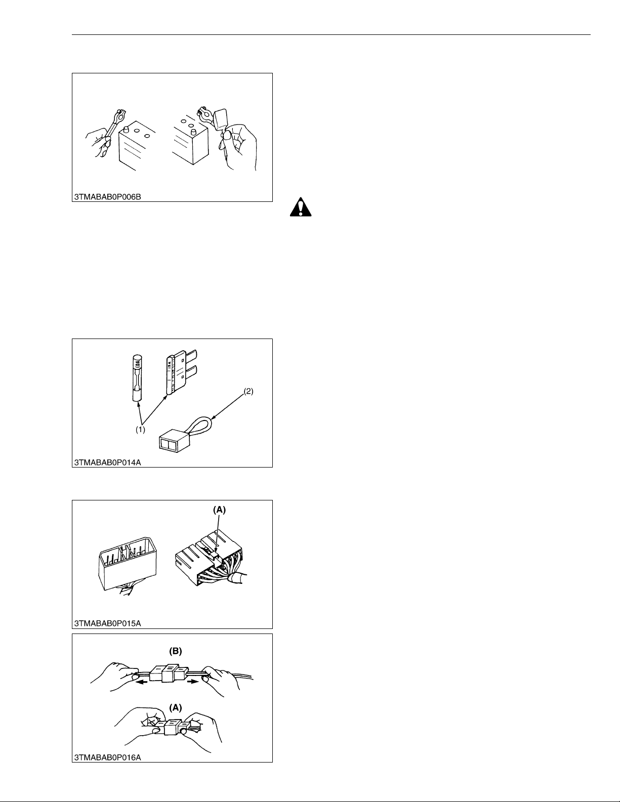
• Use fuses with specified capacity.
Neither too large or small capacity fuse is acceptable.
• Never use steel or copper wire in place of fuse.
• Do not install working light, radio set, etc. on machine which is not
provided with reserve power supply.
• Do not install accessories if fuse capacity of reserve power
supply is exceeded.
(1) Fuse (2) Slow Blow Fuse
W10120920
• For connector with lock, push lock to separate.
(A) Push
W10122110
• In separating connectors, do not pull wire harnesses.
• Hold connector bodies to separate.
(A) Correct (B) Incorrect
W10122720
G-7
GL6000, GL7000, GL9000, GL11000, WSM
KiSC issued 05, 2015 A
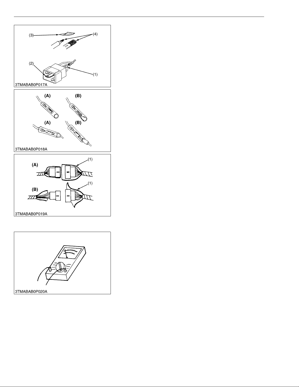
G GENERAL
• Use sandpaper to remove rust from terminals.
• Repair deformed terminal. Make certain there is no terminal
being exposed or displaced.
(1) Exposed Terminal
(2) Deformed Terminal
(3) Sandpaper
(4) Rust
W10123460
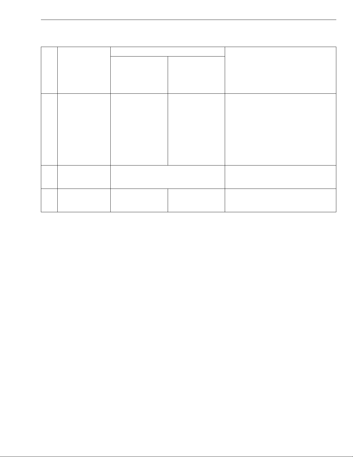
• Make certain that there is no female connector being too open.
(A) Correct (B) Incorrect
W10124300
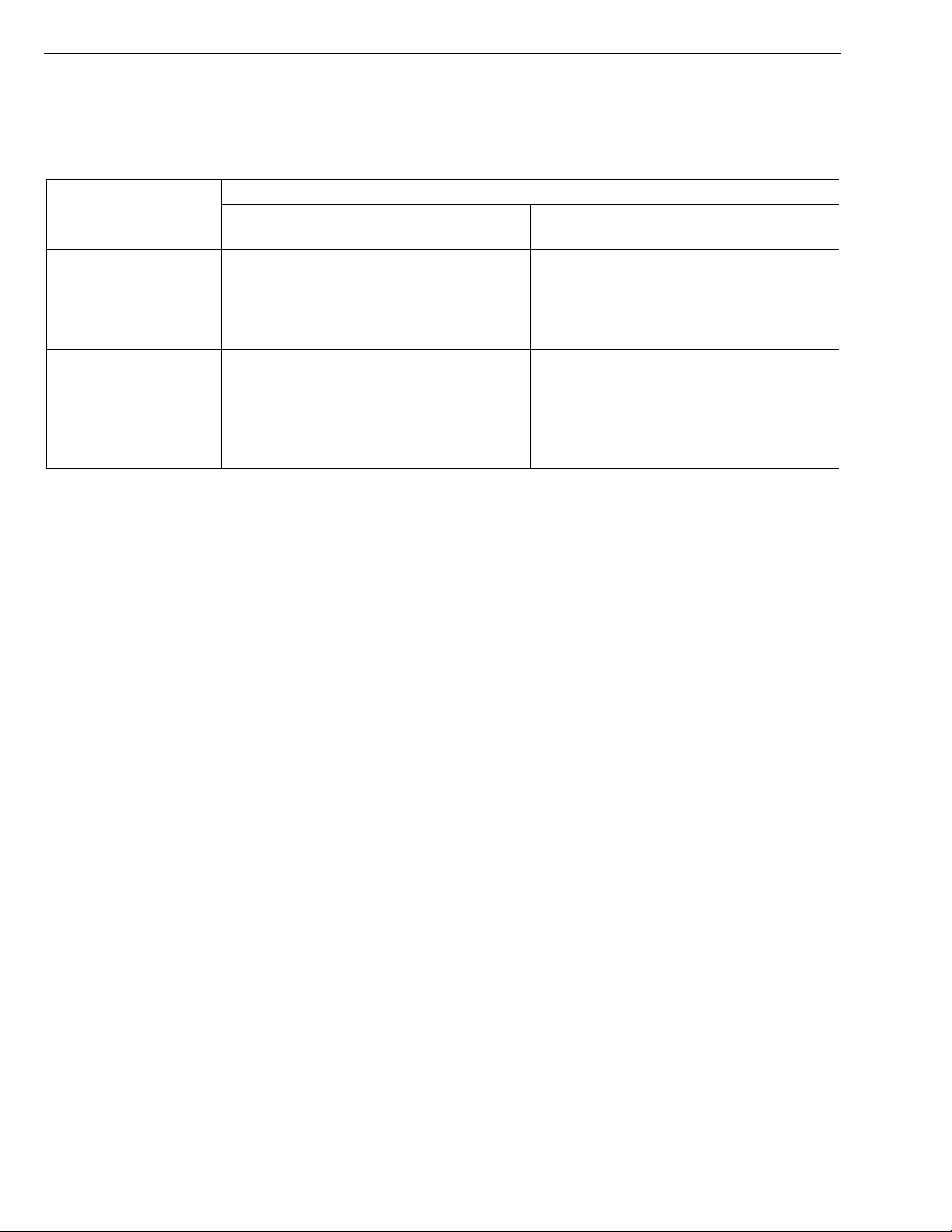
• Make certain plastic cover is large enough to cover whole
connector.
(1) Cover (A) Correct
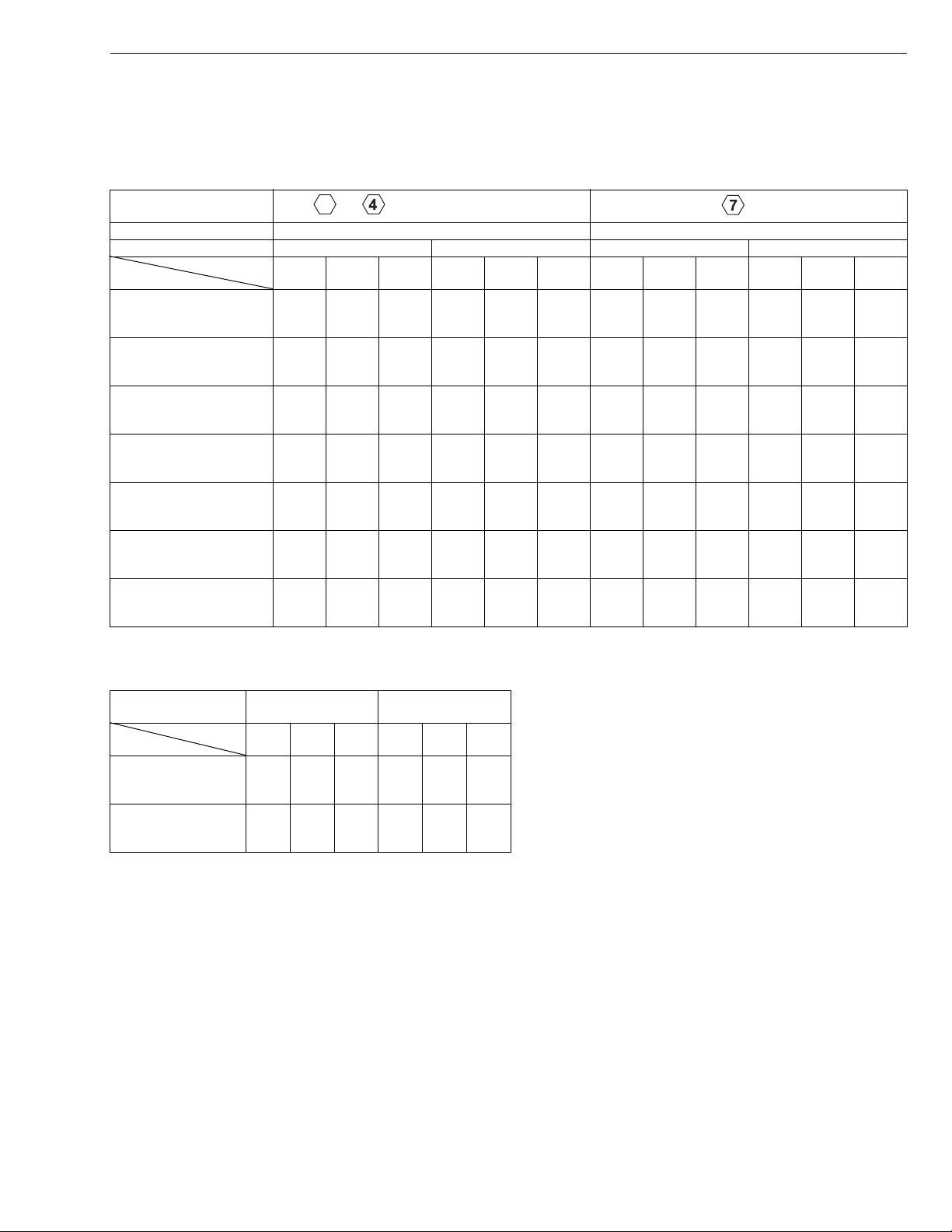
[5] HANDLING OF CIRCUIT TESTER
• Use tester correctly following manual provided with tester.
• Check for polarity and range.
(B) Incorrect
W10125190
W10126840
G-8
GL6000, GL7000, GL9000, GL11000, WSM
KiSC issued 05, 2015 A
4. LUBRICANTS, FUEL AND COOLANT
Capacity
No. Place
1 Engine oil
2Fuel
3 Coolant
GL6000-STD
GL6000-AUS
GL7000-STD
GL7000-USA
GL7000-USA-TM
2.2 L
2.3 U.S.qts.
1.9 Imp.qts.
7.4 U.S.gals.
6.2 Imp.gals.
3.7 L
3.9 U.S.qts.
3.3 Imp.qts.
GL9000-STD
GL9000-AUS
GL11000-STD
GL11000-USA
GL11000-USA-TM
3.4 L
3.6 U.S.qts.
3.0 Imp.qts.
28 L
4.1 L
4.3 U.S.qts.
3.6 Imp.qts.
Higher than CF class (API)
Above 25 °C (77 °F) : SAE10W-30,
SAE10W-30,
SAE30
0 to 25 °C (32 to 77 °F) : SAE10W-30,
SAE10W-40,
SAE20
Below 0 °C (32 °F) : SAE10W-30,
SAE10W-40,
SAE10
Refer to NOTE
Clean water (Soft water)
Use antifreeze 50 / 50
G GENERAL
Lubricants, fuel and coolant
G-9
GL6000, GL7000, GL9000, GL11000, WSM
NOTE
KiSC issued 05, 2015 A
G GENERAL
Engine Oil :
• Refer to the following table for the suitable American Petroleum Institute (API) classification of engine oil
according to the engine type (with internal EGR, external EGR or non-EGR) and the Fuel Type Used :
(Low Sulfur, Ultra Low Sulfur or High Sulfur Fuels).
Engine oil classification (API classification)
Fuel Type
High Sulfur Fuel
[0.05 % (500 ppm)
Sulfur Content <
0.50 % (5000 ppm)]
CF
(If the "CF-4, CG-4, CH-4, or CI-4" engine
oil is used with a high-sulfur fuel, change
the engine oil at shorter intervals.
(approximately half))
Engines with non-EGR
Engines with internal EGR
Engines with external EGR
–
Low Sulfur Fuel
[Sulfur Content <
0.05 % (500 ppm)] or
Ultra Low Sulfur Fuel
[Sulfur Content <
CF, CF-4, CG-4, CH-4 or CI-4
CF or CI-4
(Class CF-4, CG-4 and CH-4 engine oils
cannot be used on EGR type engines.)
0.0015 % (15 ppm)]
EGR : Exhaust Gas Re-circulation
• CJ-4 classification oil is intended for use in engines equipped with DPF (Diesel Particulate Filter) and is
Not Recommended for use in KUBOTA E3 specification engines.
• Oil used in the engine should have API classification and Proper SAE Engine Oil Viscosity according to
the ambient temperatures where the engine is operated.
• With strict emission control regulations now in effect, the CF-4 and CG-4 engine oils have been developed
for use with low sulfur fuels, for On-Highway vehicle engines. When a Non-Road engine runs on high sulfur
fuel, it is advisable to use a "CF or better" classification engine oil with a high Total Base Number (a
minimum TBN of 10 is recommended).
Fuel :
• Cetane Rating : The minimum recommended Fuel Cetane Rating is 45. A cetane rating greater than 50 is
preferred, especially for ambient temperatures below 20 °C (4 °F) or elevations above 1500 m (5000 ft).
• Diesel Fuel Specification Type and Sulfur Content % (ppm) used, must be compliant with all applicable
emission regulations for the area in which the engine is operated.
• Use of diesel fuel with sulfur content less than 0.10 % (1000 ppm) is strongly recommended.
• If high-sulfur fuel (sulfur content 0.50 % (5000 ppm) to 1.0 % (10000 ppm)) is used as a diesel fuel, change
the engine oil and oil filter at shorter intervals. (approximately half)
• DO NOT USE Fuels that have sulfur content greater than 1.0 % (10000 ppm).
• Diesel fuels specified to EN 590 or ASTM D975 are recommended.
• No.2-D is a distillate fuel of lower volatility for engines in industrial and heavy mobile service. (SAE J313
JUN87)
• Since KUBOTA diesel engines of less than 56 kW (75 hp) utilize EPA Tier 4 and Interim Tier 4 standards,
the use of low sulfur fuel or ultra low sulfur fuel is mandatory for these engines, when operated in US EPA
regulated areas. Therefore, please use No.2-D S500 or S15 diesel fuel as an alternative to No.2-D, and use
No.1-D S500 or S15 diesel fuel as an alternative to No.1-D for ambient temperatures below 10 °C (14 °F).
1) SAE : Society of Automotive Engineers
2) EN : European Norm
3) ASTM : American Society of Testing and Materials
4) US EPA : United States Environmental Protection Agency
5) No.1-D or No.2-D, S500 : Low Sulfur Diesel (LSD) less than 500 ppm or 0.05 wt.%
No.1-D or No.2-D, S15 : Ultra Low Sulfur Diesel (ULSD) 15 ppm or 0.0015 wt.%
G-10
GL6000, GL7000, GL9000, GL11000, WSM
KiSC issued 05, 2015 A
G GENERAL
5. TIGHTENING TORQUES
[1] GENERAL USE SCREWS, BOLT AND NUTS
Screws, bolt and nuts whose tightening torque are not specified in this Workshop Manual should be tightened
according to the table below.
Indication on top of
bolt
Material of bolt SS400, S20C S43C, S48C
Material of opponent part Ordinariness Aluminum Ordinariness Aluminum
Unit
Diameter
M4
(4 mm, 0.16 in.)
M5
(5 mm, 0.20 in.)
M6
(6 mm, 0.24 in.)
M8
(8 mm, 0.31 in.)
M10
(10 mm, 0.39 in.)
M12
(12 mm, 0.47 in.)
M14
(14 mm, 0.55 in.)
No-grade or 4T 7T
N·m kgf·m lbf·ft N·m kgf·m lbf·ft N·m kgf·m lbf·ft N·m kgf·m lbf·ft
1.00
2.90
1.90
3.60
7.85
9.31
17.7
20.5
39.3
45.1
62.8
72.5
108
125
to
to
to
to
to
to
to
0.10
to
0.30
0.20
to
0.40
0.80
to
0.95
1.8
to
2.1
4.0
to
4.6
6.4
to
7.4
11. 0
to
12.8
0.70
to
2.10
1.40
to
2.70
5.79
to
6.87
13.1
to
15.1
29.0
to
33.2
46.3
to
53.5
79.6
to
92.5
---------
---------
7.85
8.82
16.7
19.6
31.4
34.3
0.80
to
0.90
1.7
to
2.0
3.2
to
3.5
–––
–––
to
to
to
5.79
to
6.50
12.3
to
14.4
23.2
to
25.3
9.81
to
11. 2
23.6
to
27.4
48.1
to
55.8
77.5
to
90.2
124
to
147
1.00
to
1.15
2.4
to
2.8
4.9
to
5.7
7.9
to
9.2
12.6
to
15.0
7.24
to
8.31
17.4
to
20.2
35.5
to
41.2
57.2
to
66.5
91.2
to
108
7.85
8.82
17
20
39.3
44.1
62.8
72.5
0.80
to
to
to
to
–––
.7
.5
to
0.90
1.8
to
2.1
4.0
to
4.5
6.4
to
7.4
W1034542
5.79
to
6.50
13.1
to
15.1
29.0
to
32.5
46.3
to
53.5
[2] STUD BOLTS
Material of opponent
part
Unit
Diameter
M8
(8 mm, 0.31 in.)
M10
(10 mm, 0.39 in.)
rdin
O
N·m kgf·m lbf·ft N·m kgf·m lbf·ft
11. 8
to
15.6
24.6
to
31.3
ariness Aluminum
1.2
8.68
8.82
to
1.6
2.5
to
3.2
to
11. 5
18.1
to
23.1
to
11. 8
19.7
to
25.4
0.90
to
1.2
2.0
to
2.6
6.51
to
8.67
14.5
to
18.8
W1048139
G-11
GL6000, GL7000, GL9000, GL11000, WSM
CAUTION
KiSC issued 05, 2015 A
G GENERAL
6. MAINTENANCE CHECK LIST
Observe the following for service and maintenance.
The lubricating oil change intervals listed in the table below are for classes CG, CE and CD lubricating oil of API
classification with a low-sulfur fuel in use. If the CF-4 of CG-4 lubricating oil is used with a high-sulfur fuel, change the
lubricating oil at shorter intervals than recommended in the table below depending on the operating condition.
• When checking and servicing the generator, be sure to level and stop the engine.
Period
No.
Item
Engine oil
1
Radiator coolant (L.L.C.)
2
Air cleaner element
3
4 Fan belt
Fuel line
5
(Fuel hose and clamp bands)
6 Battery
Radiator hose and clamp bands
7
8 Oil filter cartridge Change G-15, 18
Fuel filter element
9
Valve clearance
10
Water jacket (Radiator interior)
11
Generator's brush ware
12
ator's slip-r
Gener
13
Generator's ball bearing
14
Damage in electric wiring and
15
loose connections
Fuel injection pressure
16
Nozzle spraying condition
17
Nozzle valve seat tightness
18
ing
Check G-14
Change G-15, 16
Check G-14
Change G-24
Clean G-17
Change G-24
Check G-17
Change G-23
Check G-16
Change G-25
Check G-15, 17
Change G-25
Check G-18
Change G-25
Clean G-18
Change G-19
Check G-22
Clean G-20
Check G-19
Check G-19
Check G-23
Check 2-M8
Check G-23
Check G-23
Check G-23
Daily
Initial
50
hours
Every
50
hours
Every
100
hours
Every
200
hours
Every
300
hours
Every
400
hours
Every
500
hours
Reference
page
G-12

GL6000, GL7000, GL9000, GL11000, WSM
KiSC issued 05, 2015 A
G GENERAL
Period
No.
Item
Engine oil
1
Radiator coolant (L.L.C.)
2
Air cleaner element
3
4 Fan belt
Fuel line
5
(Fuel line and clamps)
6 Battery
Radiator hose and clamps
7
8 Oil filter cartridge Change G-15, 18
Fuel filter element
9
Valve clearance
10
Water jacket (Radiator interior)
11
Generator's brush ware
12
Generator's slip-ring
13
Generator's ball bearing
14
Damage in electric wiring and
15
loose connections
Fuel injection pressure
16
Nozzle spraying condition
17
Nozzle valve seat tightness
18
Check G-14
Change G-15, 16
Check G-14
Change G-24
Clean G-17
Change G-24
Check G-17
Change G-23
Check G-16
Change G-25
Check G-15, 17
Change G-25
Check G-18
Change G-25
Clean G-18
Change G-19
Check G-22
Clean G-20
Check G-19
Check G-19
Check G-23
Check 2-M8
Check G-23
Check G-23
Check G-
Every
800
hours
Every
1000
hours
Every
1500
hours
Every 1
year
Every 2
year
Reference
page
23
W1036740
G-13
GL6000, GL7000, GL9000, GL11000, WSM
CAUTION
IMPORTANT
CAUTION
KiSC issued 05, 2015 A
7. CHECK AND MAINTENANCE
[1] DAILY CHECK
Checking Engine Oil Level
• Be sure to stop the engine before checking the engine oil
level.
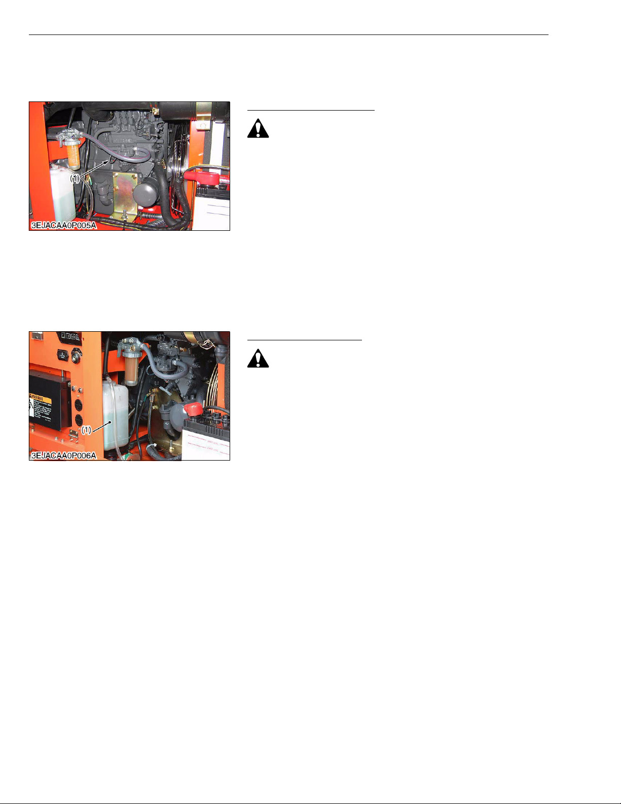
1. Level the engine and check the oil level on the gauge (1).
2. If the level below the lower mark, add new engine oil to the upper
mark.
• When using an oil of different maker or viscosity from the
previous one, drain an old oil.
• Never mix two different type's of oil.
• Use the proper SAE Engine oil according to ambient
temperatures.
Refer to "4. LUBRICANTS, FUEL AND COOLANT" (G-9).
(1) Gauge
Checking Coolant Level
G GENERAL
W1021730
• Do not remove the radiator cap while operating or
immediately after stopping. Otherwise, hot water will spout
out from the radiator. Wait for more than ten minutes to cool
the radiator, before opening the cap.
1. Remove the radiator cap and check to see that the coolant level
is just below the port.
2. If low, add coolant to the radiator.
3. Check the reserve tank (1) and keep the coolant level between
the “FULL” and “LOW” marks.
4. If low, add coolant to the reserve tank (1).
(1) Reserve Tank
W1040218
G-14
GL6000, GL7000, GL9000, GL11000, WSM
CAUTION
IMPORTANT
CAUTION
IMPORTANT
KiSC issued 05, 2015 A
[2] CHECK POINTS OF INITIAL 50 HOURS
Changing Engine Oil
• Be sure to stop engine before changing engine oil.
1. After warming up, stop the engine.
2. Place an oil pan underneath the engine.
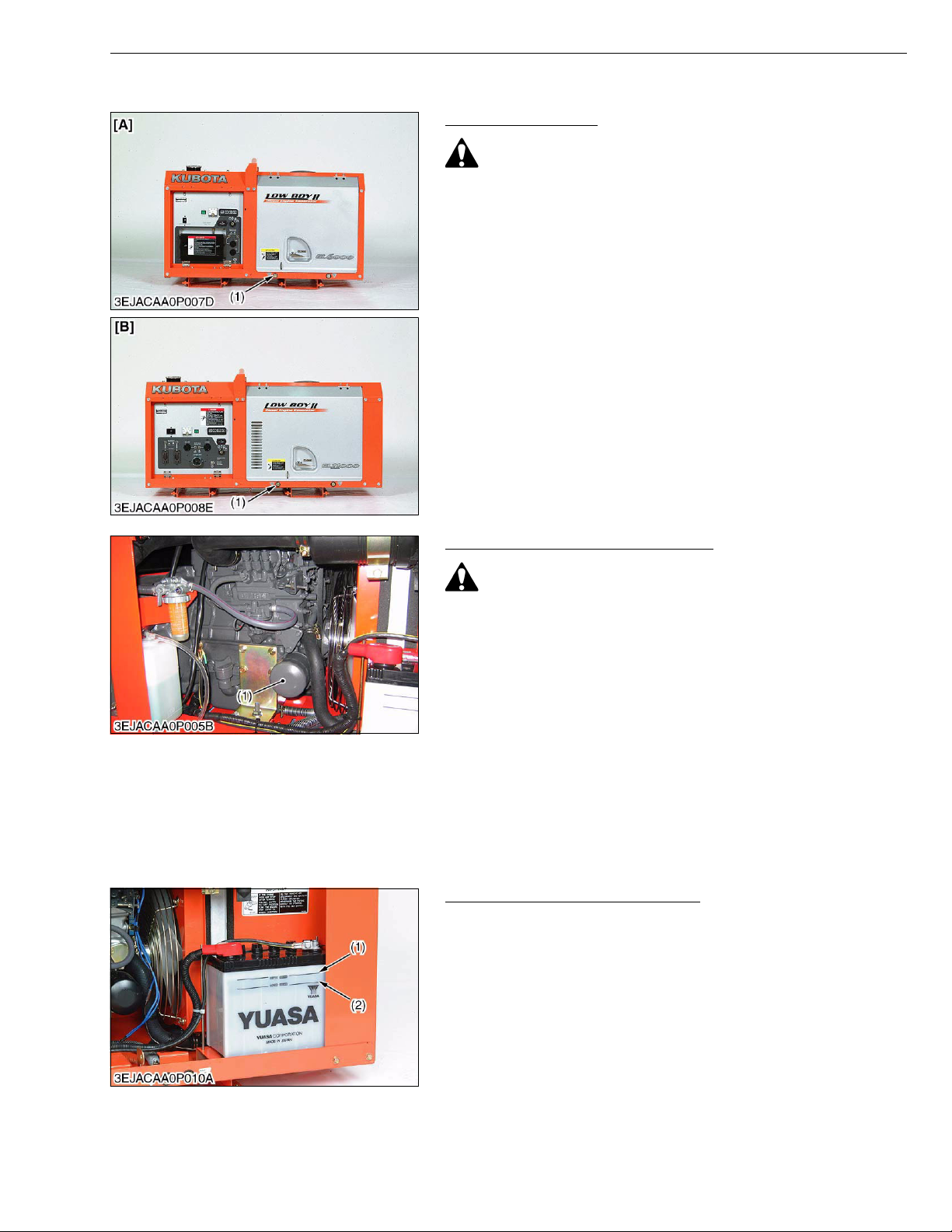
3. Remove the oil drain plug (1) to drain the dirty engine oil
completely.
4. Inspect the drain plug gasket. Replace it damaged.
5. Reinstall the drain plug.
6. Fill the new engine oil up to the upper mark on the gauge.
• When using an oil of different maker or viscosity from the
previous one, drain an old oil.
• Never mix two different type's of oil.
• Use the proper SAE Engine oil according to ambient
temperatures.
Refer to "4. LUBRICANTS, FUEL AND COOLANT" (G-9).
(1) Oil Drain Plug [A] GL6000, GL7000
G GENERAL
[B] GL9000, GL11000
W1016604
Changing Engine Oil Filter Cartridge
• Be sure to stop the engine before changing the engine oil
filter cartridge.
1. Remove the engine oil filter cartridge (1) with the filter wrench.
2. Apply engine oil slightly to the rubber gasket of new cartridge.
3. Install the new cartridge, screwing it in by hand.
Over-tightening may cause deformation of the rubber gasket.
4. After the cartridge has been changed, the engine oil level
normally lowers a little. Add engine oil to proper level.
• To prevent serious damage to the engine, replacement
element must be highly efficient. Use only a KUBOTA
genuine filter or its equivalent.
(1) Engine Oil Filter Cartridge
W1017137
Checking Battery Electrolyte Level
1. Check the battery electrolyte level.
2. If the level is below than lower level line (2), add the distilled water
to pour level of each cell.
3. If the battery can not be charged even though the electrolyte level
is correct, replace the battery.
(1) Upper Level Line (2) Lower Level Line
W1041720
G-15
GL6000, GL7000, GL9000, GL11000, WSM
CAUTION
IMPORTANT
CAUTION
IMPORTANT
KiSC issued 05, 2015 A
[3] CHECK POINT OF EVERY 50 HOURS
Checking Fuel Hose and Clamp Bands
• Stop the engine when attempting the check and change
prescribed below.
• Remember to check the fuel line periodically. The fuel line
is subject to wear and aging, fuel may leak out onto the
running engine, causing a fire.
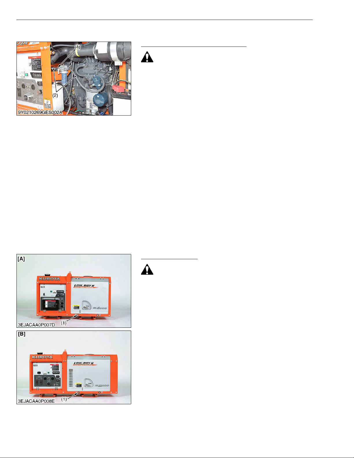
1. Check to see that all fuel lines (2) and hose clamps (1) are tight
and not damaged.
2. If fuel lines (2) and hose clamps (1) are found worn or damaged,
replace or repair them at once.
3. The fuel line (2) is made of rubber and ages regardless of period
of service. Replace the fuel line (2) together with the hose clamp
(1) every two years and securely tighten.
4. However if the fuel lines (2) and hose clamps (1) are found
damaged or deteriorated earlier than two years, then change or
remedy.
• When the fuel line is disconnected for change, close both
ends of the fuel line with a piece of clean cloth or paper to
prevent dust and dirt from entering. Entrance of dust and
dirt causes malfunction of the fuel injection pump. In
addition, particular care must be taken not to admit dust and
dirt into the fuel pump.
(1) Hose Clamp (2) Fuel Line
G GENERAL
W1035921
[4] CHECK POINT OF EVERY 100 HOURS
Changing Engine Oil
• Be sure to stop engine before changing engine oil.
1. After warming up, stop the engine.
2. Place an oil pan underneath the engine.
3. Remove the oil drain plug (1) to drain the dirty engine oil
completely.
4. Inspect the drain plug gasket. Replace it damaged.
5. Reinstall the drain plug.
6. Fill the new engine oil up to the upper mark on the gauge.
• When using an oil of different maker or viscosity from the
previous one, drain an old oil.
• Never mix two different types' of oil.
• Use the proper SAE Engine oil according to ambient
temperatures.
Refer to "4. LUBRICANTS, FUEL AND COOLANT" (G-9).
(1) Oil Drain Plug [A] GL6000, GL7000
[B] GL9000, GL11000
W1014131
G-16
 Loading...