

Page 1
1BDAIBAAP0010
MODELS GF1800-R-2
MODELES GF1800E-R-2
G
F
1
8
0
0
-
R
2
·
G
F
1
8
0
0
E
-
R
2
PRINTED IN JAPAN
IMPRIME AU JAPON
©
KUBOTA Corporation 2014
English, French (Canada)
Code No.
N° de code.
K3312-6293-2
Page 2
GF1800-R-2/GF1800E-R-2 (Canada)
AU . C . 3 - 3 . 0 . AK
California Proposition 65
WARNING
Engine exhaust, some of its constituents,
certain vehicle components and fluids,
contain or emit chemicals known to the
State of California to cause cancer and birth
defects or other reproductive harm.
Page 3

3
SAFETY FIRST
IMPORTANT :
NOTE :
3
DANGER :
3
WARNING :
3
CAUTION :
Indicates an imminently hazardous situation which, if not
avoided, will result in death or serious injury.
Indicates a potentially hazardous situation which, if not
avoided, could result in death or serious injury.
Indicates a potentially hazardous situation which, if not
avoided, could result in minor or moderate injury.
Indicates that equipment or property damage could result if
instructions are not followed.
Gives helpful information.
This symbol, the industry's ''Safety Alert Symbol'', is used throughout this manual
and on labels on the machine itself to warn of the possibility of personal injury.
Read these instructions carefully. It is essential that you read the instructions and
safety regulations before you attempt to assemble or use this unit.
FOREWORD
You are now the proud owner of a KUBOTA FRONT MOWER. This machine is a
product of KUBOTA's quality engineering and manufacturing. It is made of excellent
materials and under a rigid quality control system. It will give you long, satisfactory
service. To obtain the best use of your machine, please read this manual carefully. It
will help you become familiar with the operation of the machine and contains many
helpful hints about machine maintenance. It is KUBOTA's policy to utilize, as quickly
as possible, every advance in our research. The immediate use of new techniques
in the manufacturing of products may cause some small parts of this manual to
become outdated. KUBOTA distributors and dealers will have the most up-to-date
information. Please do not hesitate to consult them.
Page 4

SAFE OPERATION ........................................................1
1. SERVICING.....................................................................9
2. SPECIFICATIONS ........................................................10
3. INSTRUMENT PANEL AND CONTROLS ....................11
3.1 INSTRUMENT PANEL ..........................................11
3.2 CONTROLS ..........................................................12
4. OPERATING INSTRUCTIONS .....................................17
4.1 PRE-START CHECKS ..........................................17
4.2 OPERATING THE ENGINE ..................................17
4.3 OPERATING THE MACHINE ................................18
4.4 CHECK DURING OPERATING .............................19
5. MAINTENANCE ............................................................20
5.1 DAILY CHECK .......................................................20
5.2 LUBRICANTS, FUEL AND COOLANT ..................21
5.3 MAINTENANCE CHECK LIST ..............................22
6. CHECK AND MAINTENANCE .....................................24
6.1 FUEL .....................................................................24
6.2 ENGINE OIL ..........................................................25
6.3 TRANSMISSION FLUID ........................................26
6.4 PTO GEAR CASE FLUID ......................................28
6.5 REAR AXLE DIFFERENTIAL CASE FLUID
(4WD) ....................................................................28
6.6 REAR AXLE GEAR CASE FLUID (4WD) ..............28
6.7 OILING AND GREASING POINTS .......................29
6.8 INTAKE AIR LINE ..................................................30
6.9 RADIATOR ............................................................31
6.10 AIR CLEANER ......................................................33
6.11 BATTERY ..............................................................34
6.12 TIRE PRESSURE .................................................35
6.13 FUSE .....................................................................35
6.14 CHECKING ENGINE START SYSTEM ................36
6.15 CHECKING OPC SYSTEM ...................................36
6.16 REPLACING LIGHT BULB ....................................37
7. ADJUSTMENTS ...........................................................38
7.1 FAN DRIVE BELT TENSION .................................38
7.2 BRAKE ..................................................................38
7.3 REAR AXLE (2WD) ...............................................39
8. TROUBLESHOOTING ..................................................40
8.1 BATTERY TROUBLESHOOTING .........................40
8.2 MACHINE TROUBLESHOOTING .........................40
8.3 ENGINE TROUBLESHOOTING ...........................41
9. LONG-TERM STORAGE ..............................................42
10. WIRING DIAGRAM .....................................................43
Page 5
SAFE OPERATION
1
Careful operation is your best insurance against an
accident. Read this section carefully before operating
the machine. All operators, whether experienced or
not, should read this and other related manuals before
operating the mower or any attachment on it. It is the
owner's obligation to instruct all operators in safe
operation.
This cutting machine is capable of amputating hands
and feet and throwing objects. Failure to observe the
following safety instructions could result in serious
injury or death.
1. BEFORE OPERATING
(1) Know your equipment and its limitations. Read this
entire manual before attempting to start and operate
the machine.
(2) Know the controls and how to stop quickly.
(3) Pay special attention to the warning, caution and
danger labels on the machine itself.
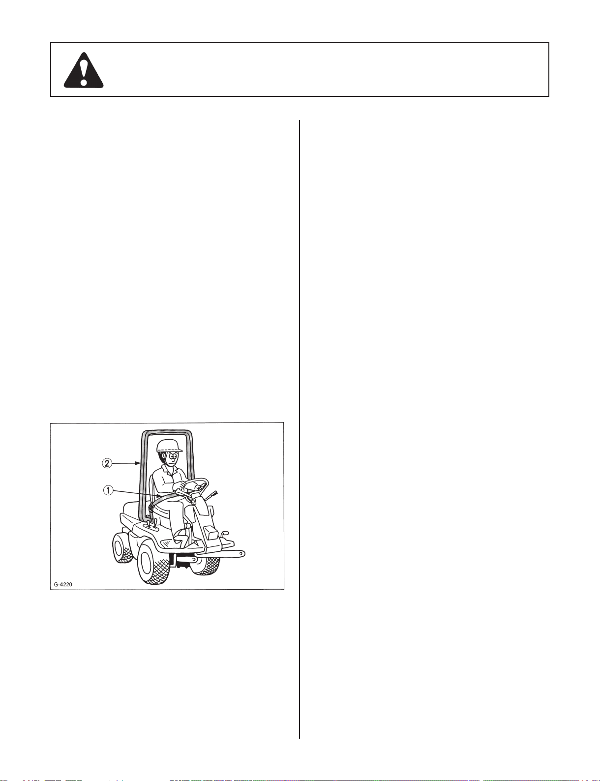
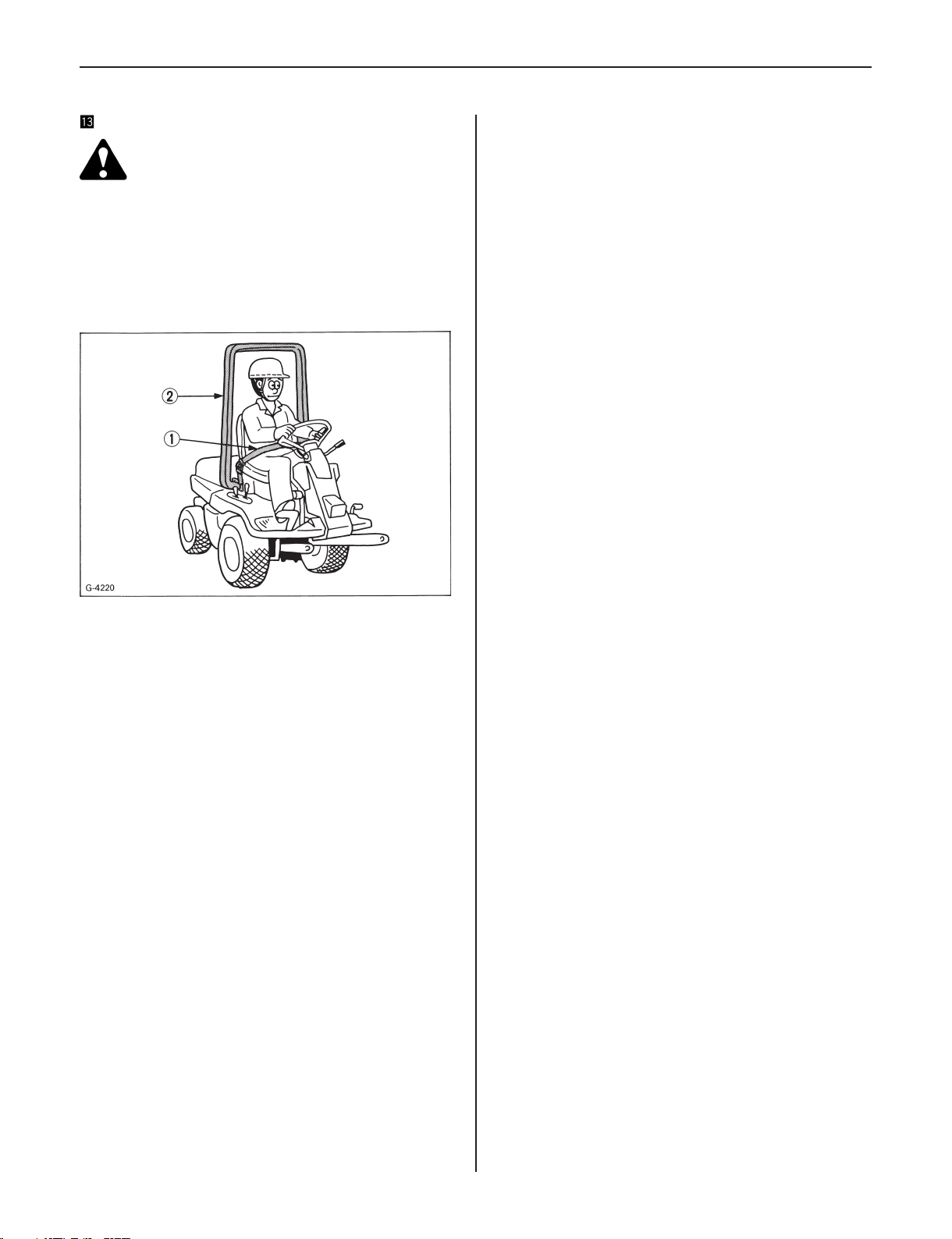
(4) KUBOTA recommends the use of a ROPS (Roll Over
Protective Structure) and seat belt in almost all
applications. This combination will reduce the risk
of serious injury or death should the machine tip
over.
Thismachineisintendedtouseonatterrain.
(1) Seat belt (2) ROPS
(5) Always use the seat belt if the machine has a ROPS.
Never fasten the seat belt without a ROPS. Check the
seat belt daily and replace if frayed or damaged.
(6) Never modify or repair a ROPS. Welding, bending,
drilling or cutting any portion of the ROPS will
weaken the ROPS structure. If any structural
member is damaged, replace the entire structure at
your local KUBOTA dealer.
(7) Do not operate the machine or any attachments
while under the inuence of alcohol, medication,
controlled substances or when fatigued.
(8) Check brakes, clutch, and other mechanical parts
for correct adjustment and wear. Replace worn or
damaged parts promptly. Check the tightness of all
nuts and bolts regularly. (For further details, see
MAINTENANCE AND ADJUSTMENTS section.)
(9) Keep all shields and guards in place. Replace any
that are damaged or missing.
(10) Carefully check the vicinity before operating the
machine or any attachments to it. Clear the work
area of objects (wires, rocks, etc.) that might be
picked up and thrown. Do not allow any bystanders
around or near machine during operation.
(11) Before allowing other people to use your machine,
explain how to operate and have them read this
manual before operation.
(12) Never wear loose, torn, or bulky clothing around
machine. The clothing may catch on moving parts
or controls. Wear and use any additional safety
items such as hard hat, safety boots or shoes, eye
and hearing protection, gloves, etc. As appropriate
or required.
(13) Neverallowpassengers ornon-qualiedoperators
on the machine at any time. You must operate the
machine from the seat only.
(14) Keep your machine clean. Accumulations of dirt,
grease,andtrashcancontributetoresandleadto
personal injury.
(15) In addition to the design and conguration of
equipment, hazard control and accident prevention
are dependent upon the awareness, concern, and
prudence of personnel involved in the operation,
transport, maintenance, and storage of equipment
or in the use and maintenance of facilities.
(16) Use only implements recommended by KUBOTA.
Use proper ballast to front or rear of machine
to reduce the risk of upsets. Follow the "SAFE
OPERATION"procedures,speciedinthemanuals
included with equipment.
(17) Follow the maintenance recommendations. See
"Maintenance and Lubrication".
(18) It is recommended that your machine be thoroughly
inspected at least once a year by an authorized
KUBOTA Dealer.
(19) This machine is equipped with many safety devices.
Do not attempt to remove or alter them.
(20) The exhaust gas from the mufer is very hot. To
preventre,donotexposedrygrass,mowedgrass,
oil or any other combustible materials to exhaust
gas. Use a spark arrester where required. Also keep
Page 6

2
the engine and mufer clean all the time. Replace
themuferifithasafault.
(21) While mowing, always wear substantial foot wear
and long trousers. Do not operate the equipment
when barefoot or wearing open sandals.
(22) Do not wear radio or music headphones while
operating the machine. Safe operation requires your
full attention.
(23) Keep the machine and attachments in good operating
condition and keep safety devices in place and in
proper working condition.
(24) Do not modify the machine. Unauthorized
modicationmayaffectthefunctionofthemachine,
which may result in personal injury.
(25) Keep all nuts, bolts, and screws tight to be sure
the equipment is in safe working condition.
Check the mower blade mounting bolts for proper
tightness at frequent intervals. On multi-bladed
mowers, take care as rotating 1 blade can cause
other blades to rotate.
2. OPERATING
Starting
♦
(1) Always sit in the operator's seat when starting
engine or operating levers or controls.
(2) Before starting the engine make sure that all
levers and speed control pedal are in neutral, the
parking brake is engaged, and Power Take Off is
disengaged.
(3) Do not start engine by shorting across starter
terminals. The machine may start in gear and move
if normal starting circuitry is bypassed.
(4) Do not operate or idle engine in a non-ventilated
area. Carbon monoxide gas is colorless, odorless,
and deadly.
(5) Do not "ride" the brake pedal. Use brake for stopping
only.
♦
Operating
(1) Keep all shields and guards in place. Replace any
that are damaged or missing.
(2) Do not drive at high speed or turn the machine when
the differential is locked.
(3) Do not operate near ditches, holes, embankments, or
other terrain which may collapse under the machine
weight. The risk of machine tip over increases when
the ground is loose or wet.
(4) To avoid tip over, operate up and down slopes, not
across. Avoid sudden starts and stops on slopes.
Slow down, and use extra caution when changing
directions on a slope.
Parkthemachineonarm,levelsurface.
(5) Watch where you are going at all times. Watch for
and avoid obstacles. Be alert at curbs, near trees,
and other obstructions and hidden hazards.
(6) When working in cooperation with other operators,
always let others know what you are doing ahead of
time.
(7) Never try to mount or dismount a moving machine.
(8) Do not operate the machine with bare feet. Keep
hands, feet, and clothing away from power-driven
parts.
(9) Do not drive machine on streets or highways. Watch
for trafc when you cross roads or operate near
roads.
(10) Look to the rear before and when backing. You
must disengage blades before shifting into reverse.
Make sure the area immediately behind you is clear
of obstructions or holes and small children. Use
extra caution when machine is equipped with Grass
Catcher.
(11) Do not cross gravel roads with the PTO engaged.
(12) Do not drive at high speed or turn the front mower
when the differential is locked. (2WD)
(13) Do not depress 4WD release pedal on slopes. (4WD)
(14) Be aware of the mower discharge direction and do
not point it at anyone.
(15) When using any attachments, never direct discharge
material toward bystanders. Do not allow anyone
near the attachments while in operation.
Do not mow when bystanders are present in the
mowing area.
(16) To reduce re hazards, keep the engine exhaust
area free of grass or leaves.
(17) Be sure rotating blades and engine are stopped and
the key is removed before placing hands or feet
near blades.
(18) Shut the engine off and wait for all movement to stop
before unclogging the chute of the grass catcher. [if
equipped]
(19) Always inspect the mower and the grass catcher [if
equipped] after striking any foreign object. This will
insure that all mower and grass catcher parts are
safe and secure and not damaged.
Repair or replace any damaged parts before re-
starting.
(20) Operateduringdaylightorinbrightarticiallight.
(21) Do not operate the mower without either the grass
container or the guard in place.
Be aware of the mower discharge direction and do
not point it at anyone.
(22) Stop the blades rotating before crossing surface
other than grass.
(23) If the machine starts to vibrate abnormally,
disengage the drive to the attachments, stop the
engine and remove the key. Then check the machine
immediately.
(24) Do not operate the machine when there is a possibility
of lightning. Even if the machine is equipped with a
cabin, the operator is not protected from lightning.
Page 7

3
Operation on slopes
♦
Slopes are a major factor related to loss-of-control and
tip-over accidents, which can result in severe injury or
death. All slopes require extra caution. If you cannot
back up the slope or if you feel uneasy on it, do not mow
it. The control of a ride-on machine sliding on a slope will
not be regained by the application of the brake.
Do not lift the grass container on a slope.
•
DO
(1) To avoid tip over, operate up and down slowly, not
across. Stay off hills and slopes too steep for safe
operation.
(2) Remove obstacles such as rocks, tree limbs, etc.
(3) Stay alert for holes in the terrain and other hidden
hazards. Keep away from drop-offs. Uneven terrain
could overturn the machine. Tall grass can hide
obstacles.
(4) Follow KUBOTA's recommendations for wheel
weights or counterweights to improve stability.
(5) The weight of grass in the grass container may
increase the possibility of tip over. [if equipped]
(6) Keep all movement on slopes slow and gradual. Do
not make sudden changes in speed or direction.
(7) Avoid starting or stopping on a slope. If tires lose
traction, disengage the blades and proceed slowly
straight down the slope.
(8) Reduce speed and exercise extreme caution on
slopes and in sharp turns to prevent tip-over or loss
of control.
(9) Use special caution when changing direction on
slopes.
(10) Shift "High - Low Gear Shift Lever" to the Low
position when mowing or operating on slopes.
DO NOT
(1) Do not turn on slopes unless necessary and then
turn slowly and gradually downhill, if possible.
(2) Do not use the machine on slopes of more than
14°.
(3) Do not mow near drop-offs, ditches, or embankments.
The machine could suddenly turn over if a wheel
falls over the edge of a cliff or ditch, or if an edge
caves in.
(4) Do not mow on wet grass. Reduced traction could
cause sliding.
(5) Do not try to stabilize the machine by putting your
foot on the ground.
(6) Do not use the grass catcher on steep slopes. [if
equipped]
(7) Do not stop or start suddenly when going uphill or
downhill.
(8) Never "freewheel". Do not let the machine travel
downhill with speed control pedal at neutral
position.
(9) Do not use the trailer and the towing implement.
♦
Children
Tragic accidents can occur if the operator is not alert to
the presence of children. Children are attracted to the
machine and the mowing activity. Never assume that
children will remain where you last saw them.
(1) Keep children out of the mowing area and under the
watchful care of another responsible adult.
(2) Be alert and turn the machine off if children enter
the area.
(3) Before and when backing, look behind and down for
small children.
(4) Never carry children. They may fall off and be
seriously injured or interfere with safe machine
operation.
(5) Never allow children to operate the machine, even
under adult supervision. Local regulation can
restrict the age of the operator.
(6) Use extra care when approaching blind corners,
shrubs, trees, or other obstructions that might hide
children from sight.
♦
Operators, age 60 years and above
Data indicates that operators, age 60 years and above,
are involved in a large percentage of machine-related
injuries. These operators should evaluate their ability to
operate the machine safely enough to protect themselves
and others from serious injury.
♦
Stopping
(1) Make sure that the machine has come to a complete
stop before dismounting.
(2) Before dismounting, disengage the PTO, lower all
attachments, place all control levers in their neutral
positions, apply parking brake, turn off the engine,
and remove the key switch.
(3) Make sure that the machine and all attachments
have come to a complete stop before dismounting.
3. USING THE PTO
(1) Before installing or using PTO-driven equipment,
read the manufacturer's manual and review the
safety labels attached to the equipment.
(2) Wait until all moving components have completely
stopped before connecting, disconnecting,
adjusting, cleaning, or servicing any PTO-driven
equipment.
(3) Use the PTO with KUBOTA approved attachments.
The speed of the PTO is 2600 rpm.
Page 8
4
4. USING THE LIFT LINK
(1) Use lift link only with authorized attachments
designed for lift link usage.
(2) When using a lift link mounted attachment, be
sure to install the adequate counter ballast weight
speciedintheattachment'smanual.
5. TRANSPORTING
(1) Disengage power to attachment(s) when transporting
or not in use.
(2) Do not tow this machine. Use a suitable truck or
trailer when transporting on public roads.
(3) It is recommended that this machine not be used on
public roads.
(4) Use extra care when loading or unloading the
machine into a trailer or truck.
6. SERVICING AND STORAGE
Servicing
♦
(1) Beforeservicing, parkthemachine onarm,level
surface and apply the parking brake. Remove the
key to prevent accidental start-up.
(2) Allow the machine time to cool before touching the
engine,mufer,radiator,etc.
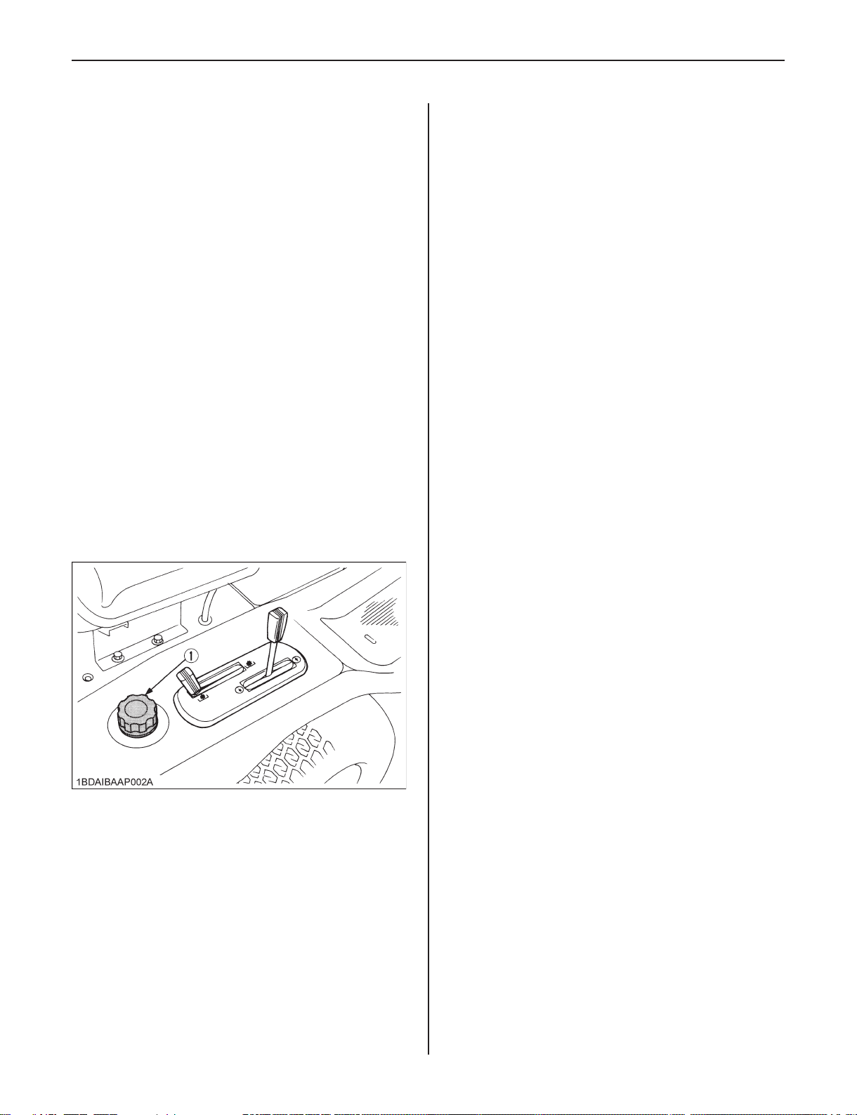
(3) Always stop the engine before refueling. Avoid spills
andoverlling.Wipeupspilledfuelimmediately.
(1) Fuel tank cap
(4) Use extra care in handling diesel fuels. They are
ammable.
(1) Use only an approved container.
(2) Do not remove fuel cap or refuel with the engine
running. Allow engine to cool before refueling.
Do not smoke while refueling or when standing
near fuel.
(3) Do not refuel the machine indoors and always
clean up spilled fuel or oil.
(4) Do not store the machine or fuel container
insidewherethereisanopename,suchasin
a water heater.
(5) If the fuel tank has to be drained, this should be
done outdoors.
(6) Replace all fuel tanks and container caps
securely.
(5) Do not change the engine governor setting or
overspeed the engine. Operating the engine at
excessive speed can increase the hazard of personal
injury.
(6) Do not smoke when working around battery or when
refueling. Keep all sparks and ames away from
battery and fuel tank. A battery, especially when
charging, will give off hydrogen and oxygen gases
which can explode and cause serious personal
injury.
(7) Before "JUMP STARTING" a dead battery, read
and follow all of the instructions to help protect
the alternator from damage due to extreme load
changes. (See "JUMP STARTING" in "OPERATING
THE ENGINE" section.)
Batteries contain sulfuric acid and produce
explosive gases. Follow the instructions below to
prevent personal injury.
Wear eye and skin protection.
•
Keepsparksandameaway.
•
Always have adequate ventilation while charging
•
or using the battery.
(8) Keeprstaid kit andreextinguisher handyatall
times.
(9) Do not remove the radiator cap while coolant is
hot.
When cool, slowly rotate cap to the rst stop and
allowsufcienttimeforexcesspressuretoescape
before removing the cap completely.
(10) Disconnect the battery's ground cable before
working on or near electric components.
(11)Donotuseorchargetherellabletypebatteryifthe
uid level is below the LOWER (lower limit level)
mark.
Otherwise, the battery component parts may
prematurely deteriorate, which may shorten the
battery's service life or cause an explosion. Check
the uid level regularly and add distilled water as
requiredsothattheuidlevelisbetweentheUPPER
and LOWER levels.
(12) Do not attempt to mount a tire on a rim unless
qualiedtodosoandallpropersafetyprecautions
are followed.
Page 9
5
(13) Alwaysmaintainthe correcttire inationpressure.
Donotinatetiresabovetherecommendedpressure
shown in the Operator's Manual.
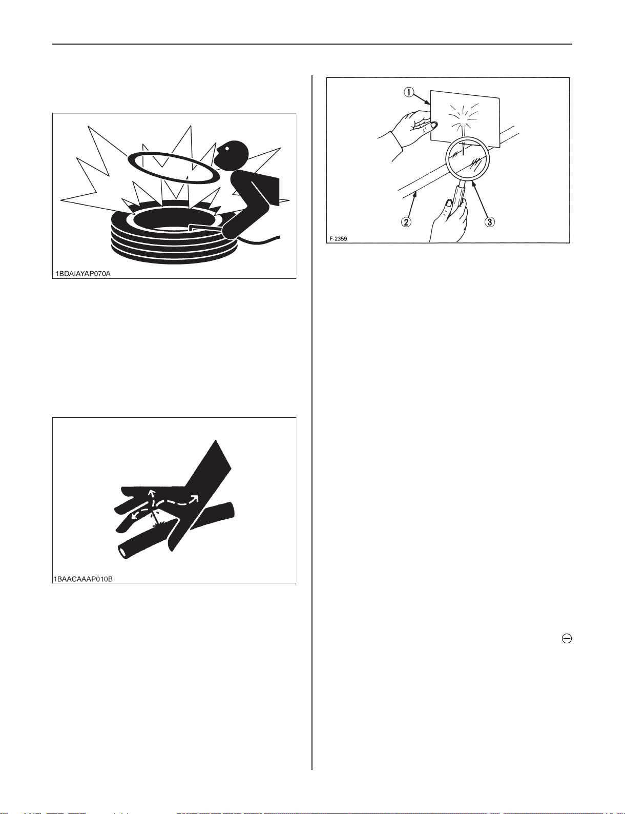
(1) Cardboard
(2) Hydraulic line
(3) Magnifying glass
(14) Provide adequate support when changing wheels or
the wheel tread width.
(15) Make sure that wheel nuts have been tightened to
thespeciedtorque.
(16) Escaping hydraulic uid under pressure has
sufcientforcetopenetratetheskincausingserious
personal injury. Before disconnecting lines, be sure
to relieve all pressure. Before applying pressure to
the system, make sure all connections are tight and
that lines, pipes, and hoses are not damaged.
Fluid escaping from pinholes may be invisible. Use a
piece of cardboard or wood to search for suspected
leaks: do not use hands. Use safety goggles or
other eye protection. If injured by escaping uid,
see a medical doctor at once.
Serious infection or reaction may result if proper
medical treatment is not administered immediately.
Thisuidcanproducegangrene orsevereallergic
reaction.
(17) Do not make adjustments or repairs with the engine
running.
(18) Keep machine free of grass, leaves, or other debris
build-up.
(19) Do not run a machine inside a closed area.
(20) Waste products such as used oil, fuel, hydraulic
uid, and batteries, can harm the environment,
people, pets and wildlife. Please dispose properly.
See your local Recycling Center or KUBOTA Dealer to
learn how to recycle or get rid of waste products.
♦
Storage
(1) Keep the machine and supply of fuel in locked
storage and remove the ignition key to prevent
children or others from playing or tampering with
them.
(2) To avoid sparks from an accidental short circuit,
always disconnect the battery's ground cable
rstandreconnectitlast.
Page 10
6
(1) Battery
(3) Do not store the machine with fuel in the tank inside
a building where fumes may ignite. Allow the engine
to cool before storing.
(4) To avoid the danger of exhaust fume poisoning, do
not operate the engine in a closed building without
adequate ventilation.
(5) Toreducerehazards,cleanthemachinethoroughly
before storage. Dry grass and leaves around the
engineandmufersmayignite.
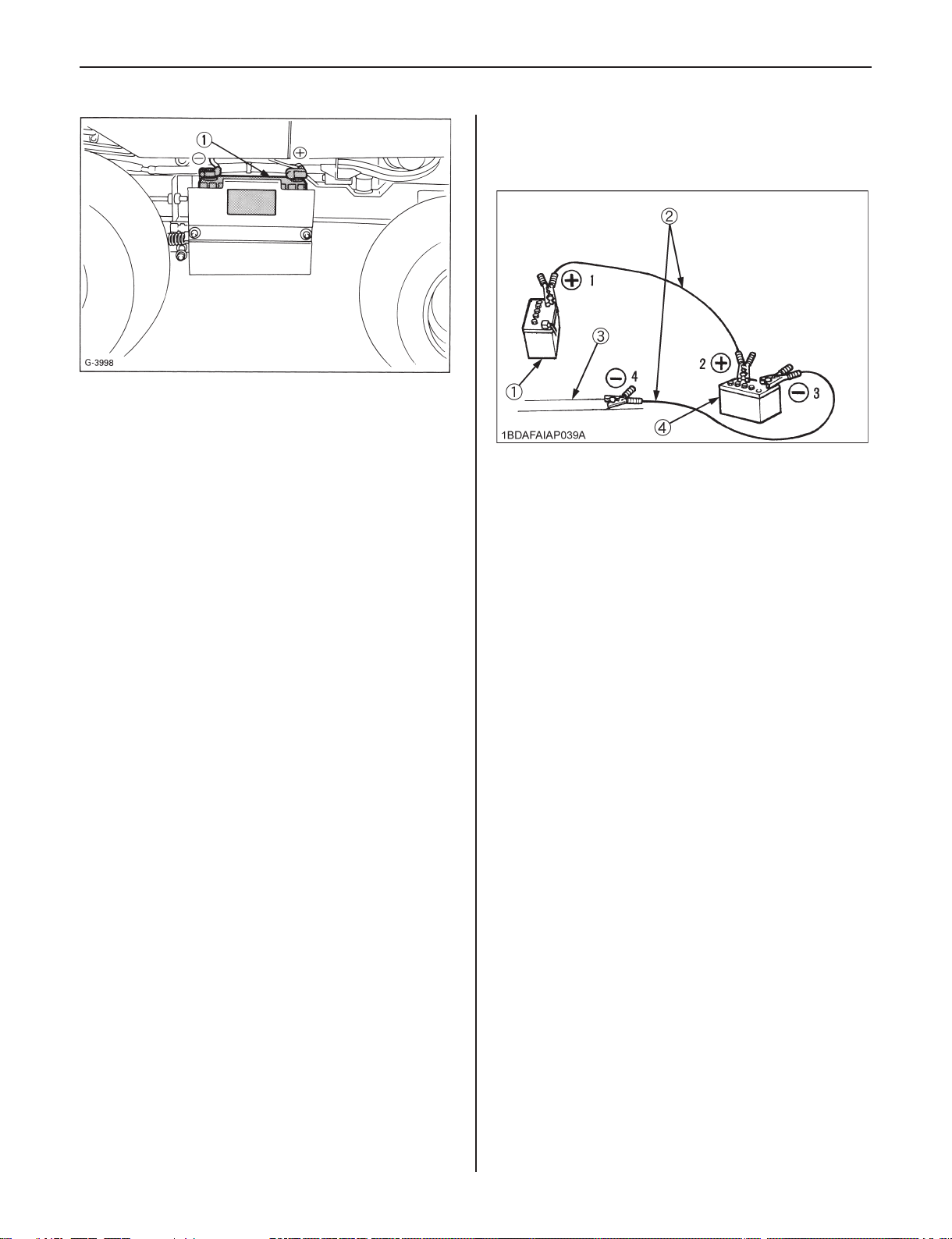
(8) Start the helper vehicle and let its engine run for a
few moments. Start the disabled machine.
(9) Disconnect the jumper cables in the exact reverse
order of attachment. (Steps 7, 6 and 5).
(1) Dead battery
(2) Jumper cables
(3) Engine block or frame
(4) Helper battery
Connect cables in numerical order.
Disconnect in reverse order after use.
7. JUMP STARTING INSTRUCTIONS AND
PRECAUTIONS
If ice is present or the battery is cracked, DO NOT
•
ATTEMPT TO "JUMP START" vehicle.
Battery gases can explode. Keep cigarettes, sparks,
•
andamesawayfrombattery.
Do not connect other end of negative (-) jumper cable
•
to negative (-) terminal of machine battery.
When jump starting the engine, follow the instructions
below to safely start the engine.
(1) Bring helper vehicle with a battery of the same
voltage as the disabled machine within easy cable
reach.
"THE VEHICLES MUST NOT TOUCH".
(2) Apply the parking brakes of both vehicles and put
the shift levers in neutral. Shut the engine off.
(3) Put on safety goggles and rubber gloves.
(4) Ensure the vent caps are securely in place. (if
equipped)
(5) Attach the red clamp to the positive (red, (+) or pos.)
terminal of the dead battery and clamp the other end
of the same cable to the positive (red, (+) or pos.)
terminal of the helper battery.
(6) Clamp the other cable to the negative (black, (-) or
neg.) terminal of the helper battery.
(7) Clamp the other end to the engine block or frame of
the disabled machine as far from the dead battery
as possible.
Page 11
7
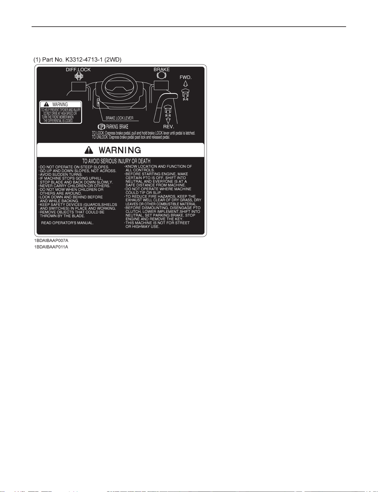
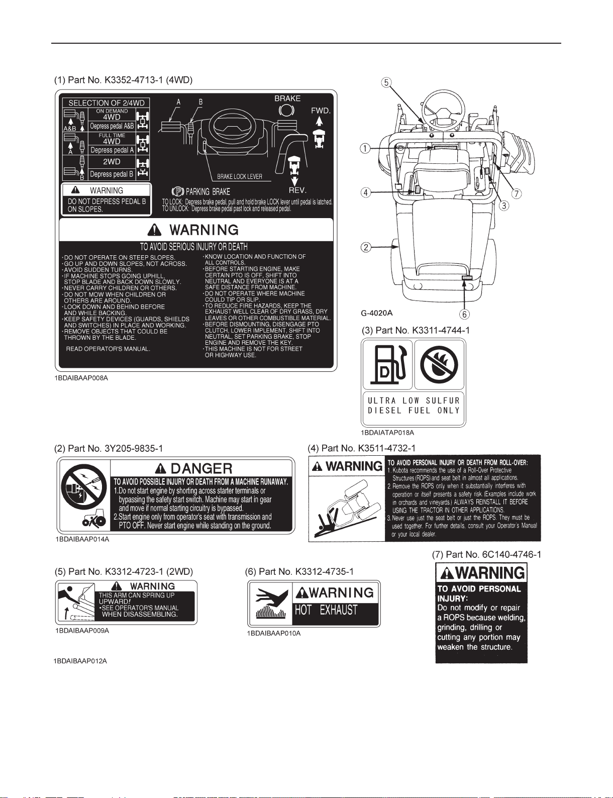
8. SAFETY LABELS
Page 12
8
CARE OF SAFETY LABELS
(1) Keep safety labels clean and free from obstructing material.
(2) Clean safety labels with soap and water, dry with a soft cloth.
(3) Replace damaged or missing safety labels with new labels from your KUBOTA dealer.
(4) If a component with safety label(s) afxed is replaced with a new part, make sure new safety label(s) is (are)
attached in the same location(s) as the replaced components.
(5) Mount new safety labels by applying on a clean, dry surface and pressing any bubbles to outside edge.
Page 13
1. SERVICING
Your dealer is interested in your new machine and has the
desire to help you get the most value from it. After reading
this manual thoroughly, you will nd that you can do some of
the regular maintenance yourself.
However, when in need of parts or major service, however,
be sure to see your KUBOTA dealer.
For service, contact the KUBOTA Dealership from which you
purchased your machine or your local authorized KUBOTA
dealer.
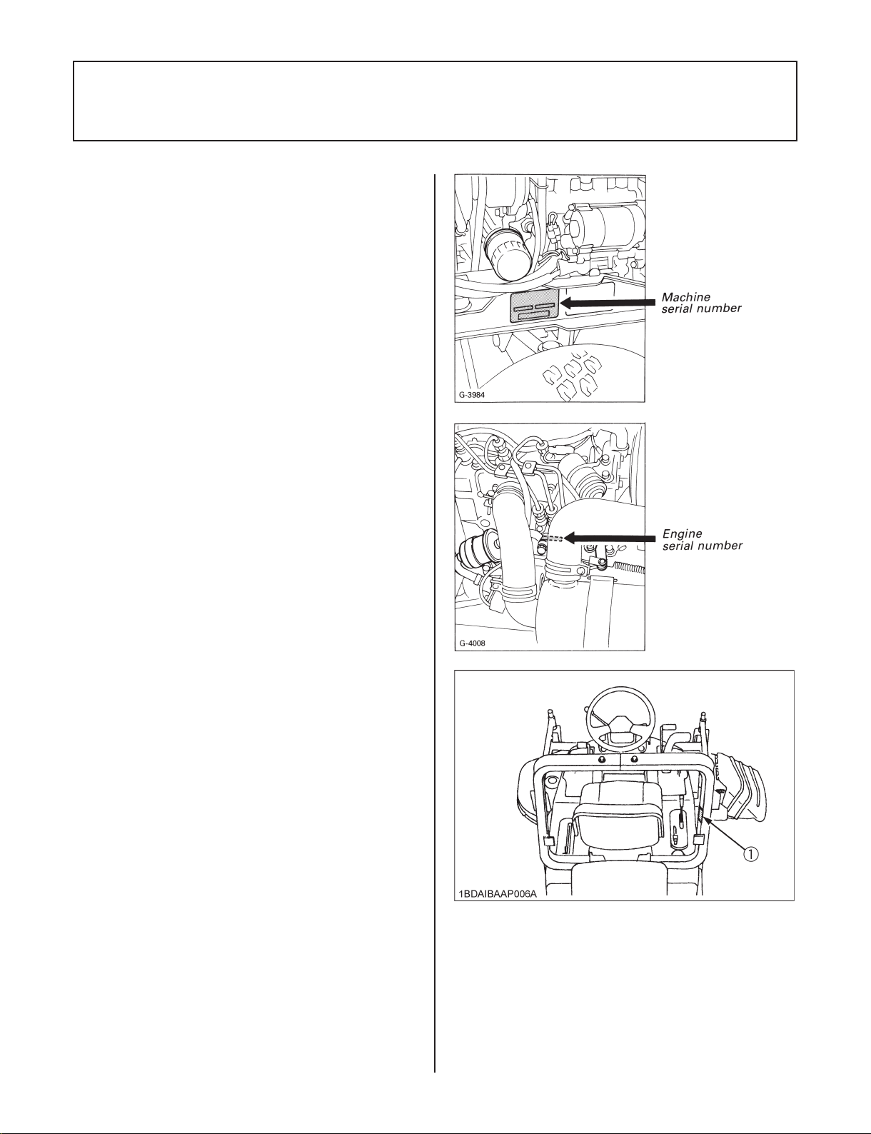
When in need of parts, be prepared to give your dealer both
the machine and engine serial numbers.
The machine serial number is located on the frame on the
left-hand side of the machine. The engine serial number is
located on the engine crankcase, right side. Locate the serial
numbers now and record them in the space provided.
KUBOTA GF1800-R-2, GF1800E-R-2
Machine Serial Number _________________________
Engine Serial Number __________________________
ROPS Serial Number ___________________________
Date of Purchase ______________________________
9
(To be lled in by purchaser)
(1) ROPS serial number
Page 14

10
2. SPECIFICATIONS
Model GF1800E-R-2 GF1800-R-2
Model D722
Type Liquid-cooled diesel
Total displacement cm³(cu.in.) 719 (43.88)
Gross power kW(HP) 13.4 (18)
Rated revolution rpm 3200
Low idling revolution rpm 1250 to 1350
No.of cylinders 3
Engine
Dimensions
Traveling
system
Seat Suspension type Coil spring
Mower drive system Shaft drive
Mower clutch type Wet multi plates
Mower PTO brake Wet single plate
Mower lift system Hydraulic
Applicable mid-mower cutting width in. 48" 54" 60"
Cutting height adjustment mm(in.) 25 to 102 (1 to 4)
Mower mounting method Quick joint, Quick mount
Step deck Semi-at
Water temperature gauge Standard
Hour meter Standard
(Specications and design subject to change without notice.)
Starter Electric starter with battery
Battery 12V 45AH
Fuel
Fuel tank capacity
Engine oil capacity L(US.qts.) 3.0 (3.2)
Radiator coolant capacity L(US.qts.)
Preheating system Super glow
Engine stop Key stop
Overall length mm(in.) 2120 (83.46) 2017 (79.4)
Overall width mm(in.) 970 (38.2)
Overall height mm(in.) 2030 (79.92)
Wheel base mm(in.) 850 (33.5)
Tread
Min, ground clearance mm(in.) 102 (4)
Weight (Fuel empty) kg(lbs) 478 (1054) 492 (1085)
Type Front 2 wheel drive 4 wheel drive
Tire size
Steering type Manual
Brake lnternal expanding shoe
Travel speed control Foot pedal with speed set lever
Transmission Hydrostatic
Traveling
speeds
Transmission oil capacity L(US.qts.) 5.7 (6.1)
Rear axle diff.case L(US.qts.) -- 1.5 (1.6)
Rear axle gear case L(US.qts.) -- 0.4 (0.4)
Front mm(in.) 724 (28.5)
Rear mm(in.) 775 (30.5) 795 (31.3)
Front 20×10.00-8
Rear 16×6.50-8
Forward km/h(mph) 0 to 13.5 (0 to 8.4)
Reverse km/h(mph) 0 to 6.5 (0 to 4.1)
L(US.gals)
Diesel fuel No.1 [below -10°C (14°F)]
Diesel fuel No.2 [above -10°C (14°F)]
20 (5.3)
3.0 (3.2)
Page 15

11
3. INSTRUMENT PANEL AND CONTROLS
3.1 INSTRUMENT PANEL
Key switch
Hour meter
Coolant temperature meter
Key Switch
OFF ........The position where the key can be inserted
into or removed from the key switch. [When the
key is turned this position, the engine stops the
moment.]
ON ..........The engine keeps running.
Preheat ... The super glow plug is heated.
Start ........ Depress the brake pedal fully and turn the key
switch to this position to start the engine.
(A) "OFF" (B) "ON" (C) "PREHEAT" (D) "START"
Head light switch
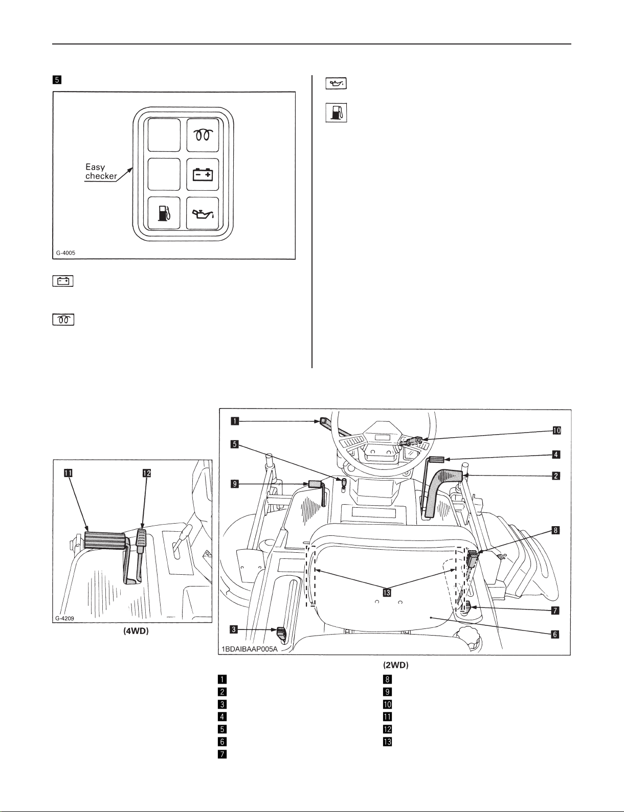
Easy checker
Hour Meter
This meter gives readings for the hours the front mower has
been operated.
As the hour meter works electrically, it starts to work when
the key switch is turned to ON.
Coolant Temperature Meter
(1) With the key switch at "ON", this meter indicates the
temperature of the coolant. "C" for "cold" and "H" for
"hot".
(2) If the indicator reaches the "H" setting (red zone),
coolant is overheated. Check the machine by referring
to "Radiator" (See page 31).
Head Light Switch
Turning the light switch clockwise illuminates the headlights.
IMPORTANT:
Because of the safety device, the engine may not be ●
started except when the PTO clutch is disengaged and
the brake pedal fully depressed.
................Head lights OFF
................Head lights ON
Page 16
12
Easy Checker
Alarm when the electrical charge system is not
functioning properly.
Glow plug Indicator (Pre-heating Indicator)
When the key switch is in the "Preheat" position,
the glow plug indicator illuminates. If the engine is
preheated completely, the glow plug indicator turns
off automatically.
Alarm when the engine oil pressure is low.
Alarm when the fuel tank is almost empty.
♦
How to check the Easy Checker
(1) When the key switch is turned "ON", all the lights
except the glow plug indicator and fuel level indicator
illuminates. When the engine starts up, all the lights
should go off.
(2) If trouble should occur at any location while the engine is
running, the warning light corresponding to that problem
comes on.
IMPORTANT:
Daily checks with the Easy Checker only, are not ●
sufcient. Always conduct daily checks carefully by
referring to "Daily Checks". (See page 20)
3.2 CONTROLS
Throttle lever
Speed control pedal
Speed set lever
Brake pedal
Parking brake knob
Seat
PTO lever
Hydraulic lift lever
Differential lock pedal (2WD)
Steering wheel tilt lever
4WD lock pedal
4WD release pedal
Seat belt
Page 17
13
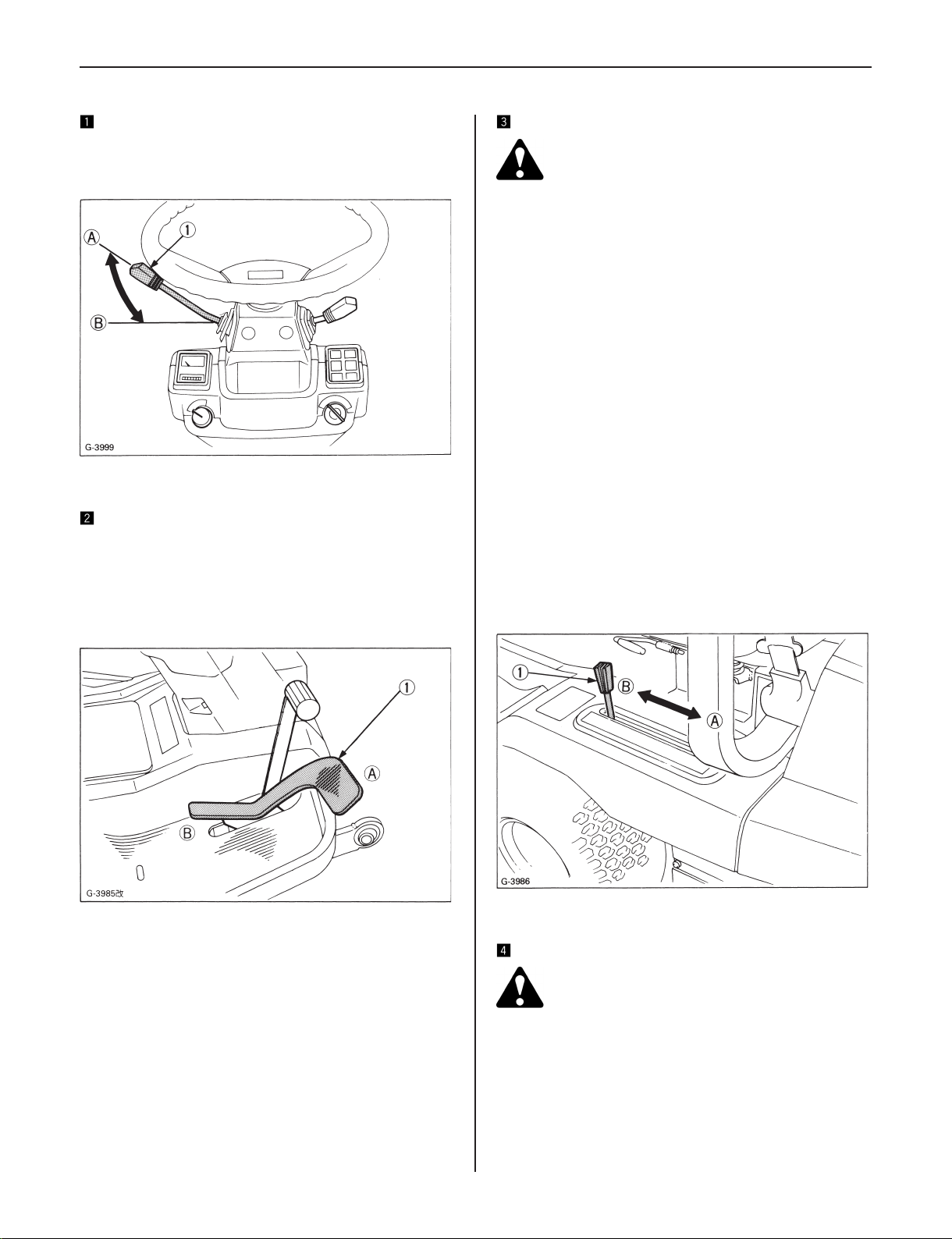
Throttle Lever
Moving the throttle lever backward decreases the engine
speed and moving it forward increases the engine speed.
(1) Throttle lever (A) "INCREASE"
(B) "DECREASE"
Speed Control Pedal
Depress the speed control pedal with your right foot to move
forward or backward.
NOTE:
When the parking brake is applied, the speed control ●
pedal is locked in the neutral position.
Speed Set Lever
WARNING
To avoid serious injury or death:
Shift the speed set lever completely to the rear ●
before starting the engine.
The speed set lever is designed for machine operating
efciency and operator comfort. This lever will provide a
constant forward operating speed by mechanically holding
the speed control pedal at the selected position.
Speed set lever cannot be set at MAX speed range.
To engage speed set lever
•
1. Accelerate speed to desired level using speed control
pedal, and move lever forward.
2. Release speed control pedal and desired speed will be
maintained.
To disengage speed set lever, move lever to "RELEASE"
•
position or can be disengaged by depressing the brake
pedal when urgent stop.
NOTE:
If the lever is not in just "RELEASE" position, it is hard to ●
depress the speed control pedal to "REVERSE".
Speed set lever is concerned with the brake pedal stroke ●
adjustment. (See page 38)
(1) Speed control pedal (A) "FORWARD"
(B) "REVERSE"
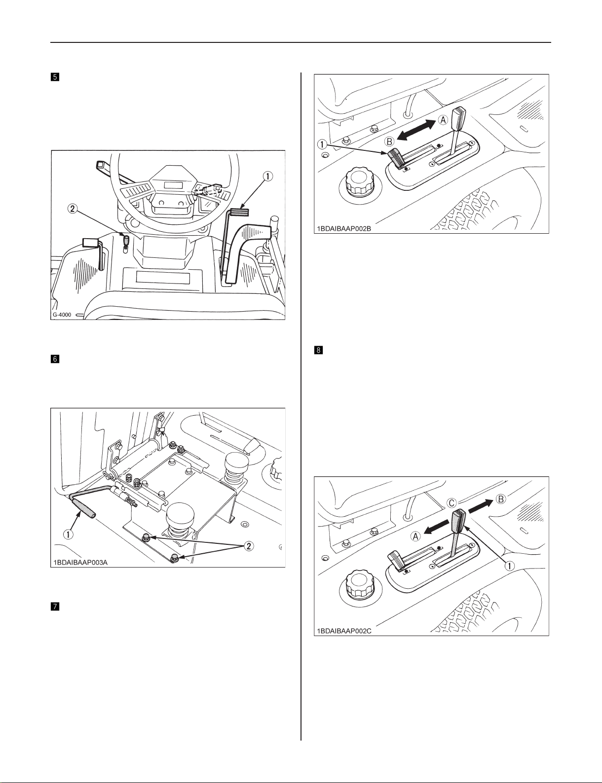
(1) Speed set lever (A) "RELEASE" (Low)
(B) "SET" (High)
Brake Pedal
WARNING
To avoid serious injury or death:
Do not depress the brake pedal quickly on ●
slopes. Quick brake will cause upset of the
machine.
(1) Depress the brake pedal to stop the machine.
Page 18
14
Parking Brake Knob
(1) To apply the parking brake:
Depress the brake pedal and hold in position.
•
Latch the brake pedal with the parking brake knob.
•
(2) To release the parking brake: Depress the brake pedal
again.
(1) Brake pedal
(2) Parking brake knob
Seat
The operator's seat position can be adjusted forward and
backward in 60 mm (2.4 in.) range by pulling the seat sliding
lever.
(1) PTO lever (A) "ENGAGE"
(B) "DISENGAGE"
(1) If you get off the seat while the PTO is running, the
engine will stop automatically. (Seat safety control)
(2) Before starting the engine, pull the PTO lever to the
disengage position. If it is at the engaged position, the
engine will not crank.
NOTE: These are built-in safety features.
Hydraulic Lift Lever
The hydraulic lift lever is used to raise and lower implement
used with the machine (ex. Mower).
To lower implement, push the lever forward.
To raise it, pull the lever back.
IMPORTANT:
Do not operate until the engine is warmed up. If operation ●
is attempted while the engine is still cold, the hydraulic
mechanism will not properly function and its service life
will be shortened.
(1) Seat sliding lever
(2) Seat attaching bolt
PTO Lever
To drive the PTO, move the PTO lever to the forward
position.
(1) Hydraulic lift lever (A) "UP"
(B) "DOWN"
(C) "NEUTRAL"
NOTE:
When equipped with the grass catcher, the mower ●
becomes somewhat heavy. While the engine is idling
with the grass catcher on, there may be a delay in lifting.
In such a case, increase the engine rpm slightly to make
the lifting smooth.
Page 19

15
Differential Lock Pedal (2WD)
WARNING
To avoid serious injury or death:
Do not drive at high speed or turn the machine ●
when the differential is locked. Release the lock
before making such a turn.
If one of the front wheels should slip, step on the differential
lock pedal.
Both wheels will then turn together, reducing slippage.
The differential lock is applied only when the pedal is
depressed.
IMPORTANT:
If the differential lock will not release when the pedal is ●
released, alternately step speed control pedal back and
forward slightly.
Do not apply the differential lock when traveling at high ●
speed, or damage to the transmission may result.
4WD Lock Pedal (A)
4WD Release Pedal (B)
WARNING
To avoid serious injury or death:
Do not depress pedal B on slopes. ●
Use the 4WD pedals when a greater traction is
required.
Depress pedals A and B on demand for a greater
•
traction.
Depress pedal A when in need of full time 4WD.
•
To release 4WD, depress pedal B.
•
IMPORTANT:
Do not steer the rear wheel sharply when engaging 4WD, ●
or damage to the turf may result.
(1) Differential lock pedal (A) "ENGAGE"
(B) "DISENGAGE"
Steering Wheel Tilt Lever
By pulling upward the steering wheel tilt lever, the lock is
released and the steering wheel can be adjusted to four tilt
angle settings.
(1) Steering wheel tilt lever
Engine Stop Lever
■
The engine stops when the key switch is turned off.
If the engine does not stop, open the hood and pull engine
stop lever (Red mark) and hold it until the engine stops.
Then contact your KUBOTA dealer immediately.
(1) Engine stop lever
Page 20
16
Seat Belt
WARNING
To avoid serious injury or death:
Always use the seat belt when the ROPS is ●
installed.
Do not use the seat belt if a foldable ROPS is ●
down or there is no ROPS.
Adjust the seat belt for proper t and connect to the buckle.
The seat belt is an auto-locking retractable type.
(1) Seat belt (2) ROPS
Page 21
4. OPERATING INSTRUCTIONS
17
4.1 PRE-START CHECKS
Before starting the engine, make pre-start checks according
to the Maintenance Schedule on page 20.
4.2 OPERATING THE ENGINE
WARNING
To avoid serious injury or death:
Read "SAFE OPERATION" in the front of this ●
manual.
Read the Safety labels located on the machine. ●
To avoid danger of exhaust fume poisoning, ●
do not operate the engine in a closed building
without proper ventilation.
Always set the speed control pedal and PTO ●
lever to the "neutral" position before starting the
engine.
Starting
■
(1) Sit on the operator's seat.
(2) Fasten the seat belt.
(3) Place the PTO lever in the "disengage" position.
(4) Place the speed control pedal in the "neutral" position.
(5) Place hydraulic control lever in "neutral" position.
(6) Set the throttle lever 1/2 of the way forward.
(7) Insert the key into the key switch and turn clockwise one
notch.
(8) Make sure that the easy checker lights are on.
(9) Turn the key switch clockwise, and hold it for about 5
seconds. (at the preheat position)
The glow plug indicator turns off for about 5 seconds.
For the appropriate preheating time, refer to the table
below:
Temperature Preheating Time
Over 0°C (32°F) 5 sec.
Below 0°C (32°F) 10 sec.
IMPORTANT:
Do not turn the key switch while the engine is running. ●
When the temperature is below 0°C (32°F), run the ●
engine at medium speed to warm up the lubricant of the
engine and transmission for at least 10 minutes. If the
machine is operated before the lubricant is warm enough,
the machine life will be shortened.
Do not operate the machine under full load until it is ●
sufciently warmed.
Do not use starting uid. ●
IMPORTANT:
When the ambient temperature is less than -15°C ●
(5°F), remove the battery from the machine and store it
somewhere warm until next operation.
Stopping
■
(1) Slow the engine down by moving the throttle lever
backward.
(2) Turn the key switch off and remove the key from the
switch.
How to Open the Hood
■
WARNING
To avoid serious injury or death from contact with
moving parts:
Never open the hood while the engine is running. ●
Donottouchmuferorexhaustpipeswhilethey ●
are hot; severe burns could result.
To open the hood, lift the lever of the front end of the hood.
(10) Depress the brake pedal fully.
(11) Turn the key switch to the start position and the starter
will turn and the engine should start.
(12) Make sure that the easy checker lights have gone off.
If the light is still on, immediately stop the engine and
check the remedy following the instruction of page 19.
(13) Warm the engine by running at medium speed.
(1) Hook
(2) Hood
Page 22

18
4.3 OPERATING THE MACHINE
WARNING
To avoid serious injury or death:
Do not allow any person other than the driver to ●
ride on the machine.
Do not drive the machine close to the edges ●
of ditches or banks which may collapse under
the weight of the machine, especially when the
ground is loose or wet.
When turning the machine, be sure to reduce the ●
travel speed by letting up on the pedal.
Do not drive at high speed or turn the machine ●
when the differential is locked.
To avoid tip over, operate up and down ●
slopes, not across. Avoid sudden starts and
stops on slopes. Slow down, and use extra
caution when changing directions on a slope.
Parkthemachineonarm,levelsurface.
Watch where you are going at all times. Watch ●
for and avoid obstacles. Be alert at curbs,
near trees, and other obstructions and hidden
hazards.
Do not drive machine on streets or highways. ●
Watch for trafc when you cross roads or
operate near roads.
Look to the rear before and when backing. You ●
must disengage blades before shifting into
reverse. Make sure the area immediately behind
you is clear of obstructions or holes and small
children. Use extra caution when machine is
equipped with Grass Catcher.
Do not drive at high speed or turn the front ●
mower when the differential is locked. (2WD)
Do not depress 4WD release pedal on slopes. ●
(4WD)
Starting
■
(1) Unlock the parking brake.
(2) Speed up the engine by moving the throttle lever
forward.
(3) Depress the speed control pedal with your right foot to
move forward or backward.
IMPORTANT:
Never move the machine with the brake on. ●
Parking
■
TO APPLY THE PARKING BRAKE:
Depress the brake pedal and hold in position.
•
Latch the brake pedal with the parking brake knob.
•
TO RELEASE THE PARKING BRAKE:
Depress the brake pedal again.
WARNING
To avoid serious injury or death:
Before leaving the operator's position,
Set parking brake. ●
Lower all implements to the ground. ●
Shut off engine. ●
Remove the key from the switch. ●
If necessary to park on an incline, be sure to chock the wheels
to prevent accidental rolling of the machine.
(1) Chocks
Transporting
■
(1) Do not tow this machine a long distance, or damage to
the transmission may result.
(2) Transport the machine on a trailer.
Fasten the machine to the trailer.
•
Prevent the hood from opening by wind by any
•
chance. If necessary, load the machine backward or
use stable strap.
Stopping
■
(1) Release the speed control pedal and depress the brake
pedal to stop the machine.
(2) Slow the engine down.
(3) Shift PTO lever to "disengage" position.
(4) Lower all attachments, place all control levers in their
neutral positions.
(5) Apply parking brake, turn off the engine and remove the
key switch.
Page 23

19
4.4 CHECK DURING OPERATING
When operating, check the following to ensure that all the
parts are functioning correctly.
Coolant
■
WARNING
To avoid serious injury or death:
Do not remove radiator ller cap until coolant ●
temperature is well below its boiling point.
Then rotate cap slightly to the stop to relieve
any excess pressure before removing cap
completely.
If engine coolant temperature meter indicator moves into the
red zone on the gauge, stop the engine and check for the
following:
(1) Shortage or leakage of the coolant.
(2) Foreign matter on the radiator net and dust and dirt
between the radiator ns and tube.
(3) Loose fan drive belt.
(4) Internal blockage in the radiator core or hose.
Exhaust Fumes
■
(1) Exhaust Fumes are colorless at normal output drive.
(2) If the color of exhaust gas becomes dark often during
driving, the engine maybe overloaded. This will result in
excessive wear to the engine, drivertrain, and tires.
Operate in a lower speed or decrease load placed on
machine.
Urgent Stop
■
Should the following take place, immediately stop the
engine.
(1) The engine suddenly slows down or speeds up.
(2) Unusual noises are suddenly heard.
(3) Exhaust suddenly become very dark.
(4) The engine oil pressure light illuminates while
operating.
(5) The battery charge light goes on while operating.
For checks and remedies in the above situations, consult
your KUBOTA dealer.
Easy Checker
■
Engine oil pressure light
•
The pressure light signals the operator that the engine oil
pressure is below the prescribed level. If the light goes on
during operation, immediately stop the engine and check the
following:
(1) The level of the engine oil. (See page 25)
(2) The conditions of the lubrication system.
Battery charge light
•
The charge light signals to the operator that the dynamo is
not charging the battery.
If the light goes on during operation, immediately stop the
engine and check for:
(1) Wiring failure.
(2) Connection failure of dynamo and regulator.
(3) Dynamo drive belt failure.
Fuel
■
Do not allow the fuel tank to empty completely.
Doing so will allow air to enter into the fuel system. Should
this happen, the fuel system must be bled. (See page 24)
Page 24

20
5. MAINTENANCE
5.1 DAILY CHECK
To prevent trouble from occurring, it is important to know the
conditions of the machine well. Check before starting.
WARNING
To avoid serious injury or death:
Be sure to check and service the machine on ●
a level surface with the engine shut off and the
parking brake on.
Reference
page
35
31
—
—
12
Walking around
the machine
While sitting in
the operator's
seat
Turning the key
switch on
No. Check item
1 The tire pressure, wear
and damage
2 Oil and water leak —
3 Engine oil level 25
4 Transmission uid level 26
5 Battery electrolyte level 34
6 Coolant level in the
recovery tank
7 Damage of machine
body, tightness of all
bolts and nuts
8 Radiator screen 33
9 Panel screen 33
10 Brake play 38
11 Oiling 29
1 Speed control pedal
Brake pedal
2 Speed set lever 13
3 Parking brake —
4 Steering wheel —
5 Seat belt and ROPS 16
1 Performance of the easy
checker light
2 Headlights —
3 Fuel level 24
No. Check item
Starting the
engine
Others 1 Check the areas where
1. Always check condition of the seat belt and ROPS
attaching hardware before operating the machine.
2. Replace anything that is frayed or damaged.
(1) Seat belt (2) ROPS
1 Color of the exhaust
fumes
2 Safety start switch and
seat safety control. If
either of these do not
operate properly, contact
your KUBOTA dealer
immediately.
3 Check for abnormal noise
and vibration.
previous trouble was
experienced.
Reference
page
19
36
—
—
Page 25

21
5.2 LUBRICANTS, FUEL AND COOLANT
To prevent serious damage to lubricating systems, use genuine KUBOTA uid or equivalent.
Place Capacity Lubricants
Fuel 20 L (5.3 U.S.gals)
Coolant 3.0 L (3.2 U.S.qts.) Fresh clean water with anti-freeze
Engine crankcase 3.0 L (3.2 U.S.qts.)*1
Transmission 5.7 L (6.1 U.S.qts.)
PTO Gear Case 0.6 L (0.63 U.S.qts.)
Rear axle differential case (4WD) 1.5 L (1.6 U.S.qts.)
Rear axle gear case (R&L) (4WD) 0.4 L (0.4 U.S.qts.)
Center pin (2WD)
King pins (2WD)
Joint shaft
Link pivot
Seat adjuster
Speed control pedal shaft
PTO drive shaft
Rear wheel drive shaft (4WD)
Knuckle arm (4WD)
Cable (Throttle)
Cable (4WD pedal)
Moderate Amount Multipurpose EP2 grease (NLGI Grade No.2)
Moderate Amount Oil
Note *1 Oil amount when the oil level is at the center of the oil level gauge
*2 The product name of KUBOTA genuine UDT uid may be different from that in the Operator's Manual depending on
countries or territories. Consult your local KUBOTA Dealer for further detail.
No.2-D diesel fuel
No.1-D diesel fuel if temperature is below -10°C
Engine oil: Refer to the NOTE below.
Above 25°C
.....SAE30, SAE10W-30 or 15W-40
0 to 25°C
.....SAE20, SAE10W-30 or 15W-40
Below 0°C
.....SAE10W, SAE10W-30 or 15W-40
KUBOTA SUPER UDT-2 uid*2
KUBOTA SUPER UDT-2 uid*2 or SAE85W, SAE90 gear oil
(API service classication: more than GL-3)
IMPORTANT
lTo prevent serious damage to hydraulic systems, use only KUBOTA genuine uid or its equivalent.
NOTE
uEngine Oil:
l Oil used in the engine should have an American Petroleum Institute (API) service classication and Proper SAE Engine Oil
according to the ambient temperatures as shown above:
l With the emission control now in effect, the CF-4 and CG-4 lubricating oils have been developed for use of a low-sulfur fuel on
on-road vehicle engines. When an off-road vehicle engine runs on a high-sulfur fuel, it is advisable to employ the "CF or better"
lubricating oil with a high Total Base Number (TBN of 10 minimum).
l Refer to the following table for the suitable API classication engine oil according to the engine type (with internal EGR, external
EGR or non-EGR) and the fuel (low-sulfur or high-sulfur fuel).
Fuel used
High Sulfur Fuel
0.05% (500 ppm)]
[
Low Sulfur Fuel
[<0.05% (500 ppm)] or
Ultra Low Sulfur Fuel
[<0.0015% (15 ppm)]
Oil class of engines except external EGR Oil class of engines with external EGR
CF
(If the "CF-4, CG-4, CH-4 or CI-4" lubricating oil is
used with a high-sulfur fuel, change the lubricating oil
at shorter intervals. (approximately half))
CF, CF-4, CG-4, CH-4 or CI-4
Engine oil classication (API classication)
---
CF or CI-4
(Class CF-4, CG-4 and CH-4 engine oils cannot
be used on EGR type engines)
Page 26

22
EGR: Exhaust Gas Re-circulation
l The CJ-4 engine oil is intended for DPF (Diesel Particulate Filter) type engines, and cannot be used on this machine.
except external EGR with external EGR
Models GF1800-R-2, GF1800E-R-2 ---
uFuel:
l Cetane number of 45 minimum. Cetane number greater than 50 is preferred, especially for temperatures below -20°C
(-4°F) or elevations above 1500 m (5000 ft).
l If diesel fuel with sulfur content greater than 0.5% (5000 ppm) sulfur content is used, reduce the service interval for engine oil
and lter by 50%.
l NEVER use diesel fuel with sulfur content greater than 0.05% (500 ppm) for EXTERNAL EGR type engine.
l DO NOT use diesel fuel with sulfur content greater than 1.0% (10000 ppm).
l Diesel fuels specied to EN 590 or ASTM D975 are recommended.
l No.2-D is a distillate fuel of lower volatility for engines in industrial and heavy mobile service. (SAE J313 JUN87)
uTransmission Oil:
The oil used to lubricate the transmission is also used as hydraulic uid. To insure proper operation of the hydraulic system and to
complete lubrication of the transmission, it is important that a multi-grade transmission uid is used in this system. We recommend
the use of KUBOTA UDT or SUPERUDTuid for optimum protection and performance.
(Consult your local KUBOTA Dealer for further detail.)
Do not mix different brands together.
lIndicated capacities of water and oil are manufacturer's estimate.
5.3 MAINTENANCE CHECK LIST
No.
Items
Engine start
1
system
2 OPC system check
3 All grease ttings grease
4 PTO drive shaft grease
Air cleaner
5
element
6 Battery condition check
7 Fuel lter element
8 Radiator core cleaning
Fan drive belt
9
tension
10 Engine oil change
Engine oil lter
11
cartridge
12 Transmission uid change
Transmission oil
13
lter cartridge
Transmission
14
strainer
PTO gear case
15
uid
Rear axle
16
differential case
uid (4WD)
check
cleaning
replacement
check
replacement
check
replacement
replacement
cleaning
change
change
Period
Every 50 Hr
(2 weekly)
¡
¡
¡
¡
50 Hr 100 Hr 200 Hr 300 Hr 400 Hr 500 Hr
¡ ¡ ¡ ¡ ¡
¡ ¡ ¡ ¡ ¡
¡ ¡ ¡ ¡ ¡
¡ ¡ ¡ ¡ ¡
Hours used
¡ ¡
¡ ¡
¡ ¡
Reference
After since
every 50 Hr 36
every 50 Hr 36
every 200 Hr 29
every 100 Hr *2 33
every 1000 Hr
or 1 year *5
every 100 Hr *7 34
every 100 Hr 25
every 500 Hr *3 25
¡
every 100 Hr
*3 38
every 200 Hr *1 25
every 200 Hr *1 26
¡
¡
¡
¡
¡
every 400 Hr 26
every 400 Hr *1 27
every 400 Hr 27
every 400 Hr 28
every 400 Hr 28
page
29
33
31
Page 27

23
No.
Items
Rear axle gear
17
case (right and
left) uid (4WD)
Fuel injection
18
nozzle injection
pressure
19 Radiator cleaning
Anti-freeze and
20
coolant
21 Injection pump check
22 Fuel line
23 Intake air line
Engine breather
24
hose
Radiator hose
25
and clamp
26 Hydraulic hose
27 Fuel system bleeding
28 Fuse replace 35
29 Light bulb replace 37
Period
change
check
change
check every 1 year *4 24
replacement every 4 years *3 24
check every 1 year *4 30
replace every 4 years 31
check every 1 year *4 —
replace every 4 years *3 —
check every 1 year *4 32
replace every 4 years *3 32
check every 1 year *4 —
replacement every 4 years *3 —
Every 50 Hr
(2 weekly)
50 Hr 100 Hr 200 Hr 300 Hr 400 Hr 500 Hr
Hours used
¡
Reference
After since
every 400 Hr 28
every 1500 Hr
*3
every 2000 Hr
or 2 years *6
every 2000 Hr
or 2 years *6
every 3000 Hr
*3
Service as
required
page
25
31
32
25
24
IMPORTANT
The jobs indicated by ●
must be done initially.
*1 The initial 50 hours should not be a replacement cycle.
*2 Air cleaner should be cleaned more often in dusty conditions than in normal conditions.
*3 Consult your local KUBOTA Dealer for this service.
*4 Replace if any deterioration (crack, hardening, scar, or deformation) or damage occurred.
*5 Every 1000 hours or every 1 year whichever comes faster.
*6 Every 2000 hours or every 2 years whichever comes faster.
*7 When the battery is used for less than 100 hours per year, check the battery condition by reading the indicator annually.
Page 28

24
6. CHECK AND MAINTENANCE
6.1 FUEL
Checking and Refueling
■
WARNING
To avoid serious injury or death:
Handle fuel carefully. If the engine is running, do ●
not ll the fuel tank. If engine is hot, let engine
cool several minutes before adding fuel. Do not
smokewhilellingthefuel tankorservicing the
fuelsystem.Fillfueltank onlytobottom ofller
neck.
(1) Bleeding screw
Bleeding the Fuel Lines
■
Air must be removed:
(1) When the fuel lter and lines are removed.
(2) When fuel tank is completely empty.
(3) After the machine has not been used for a long period of
time.
IMPORTANT:
Be careful not to spill fuel on your machine. Fuel may ●
damage plastic. Wipe up spilled fuel immediately.
Check the fuel level. Take care that the fuel tank does not
become empty.
Fuel tank capacity 20 L (5.3 U.S.gals.)
(1) Use No.2 diesel fuel.
(2) Use No.1 diesel fuel if the temperature is below -10°C
(14°F).
(3) Always use a strainer in refueling to prevent fuel injection
pump contamination.
(4) Once the fuel tank becomes empty, air admitted to the
fuel system. In such a case, it will be necessary to bleed
the fuel system before the engine will start.
IMPORTANT:
If the engine runs out of fuel and stalls, the engine ●
components may be damaged.
Be careful not to spill during refueling. If a spill should ●
occur, wipe it off at once, or it may cause a re.
To prevent condensation (water) accumulation in the fuel ●
tank, ll the tank before parking overnight.
Bleeding procedure is as follows:
WARNING
To avoid serious injury or death:
Do not bleed the fuel system when the engine is ●
hot.
(1) Fill the fuel tank with fuel.
(2) Turn the key switch to the ON position.
(3) Open the bleed screw.
When bubbles disappear from fuel coming out of the
plug, tighten the bleed screw.
Checking Fuel Line
■
WARNING
To avoid serious injury or death:
Stop the engine when attempting to check and ●
change prescribed below.
Never fail to check the fuel line periodically. The ●
fuel line is subject to wear and aging, fuel may
leakoutontotherunningengine,causingare.
(1) If the clamp is loose, apply a slight coat of lubricant onto
the threads and retighten it securely.
(2) The fuel line is made of rubber and ages regardless of
service period.
(3) After inspection, if the fuel line and clamps are found
damaged or deteriorated, replace them.
Page 29

(4) After the fuel line and clamp have been replaced, bleed
the fuel system.
IMPORTANT:
When the fuel line is disconnected for maintenance ●
or repair, close both ends of the fuel line with a piece
of clean cloth or paper to prevent dust and dirt from
entering. Entrance of dust and dirt causes malfunction of
the fuel injection pump. In addition, particular care must
be taken not to admit dust and dirt into the fuel pump.
Fuellter
■
Change fuel lter every 500 hours.
25
(1) Fuel lter
Checking Fuel Injection Nozzle Injection
■
Pressure
Consult your local KUBOTA Dealer for this service.
Checking Injection Pump
■
Consult your local KUBOTA Dealer for this service.
6.2 ENGINE OIL
Oil level check and Replenishment
■
(1) Engine oil port
(2) Oil dipstick
(4) When using a different brand or viscosity oil from the
previous one, remove all of the old oil. Never mix two
different types of oil.
(5) Use the proper Engine Oil SAE according to the ambient
temperatures. (See page 21)
Engine Oil Change
■
(A) "UPPER LEVEL"
(B) "LOWER LEVEL"
WARNING
To avoid serious injury or death:
Before changing the oil, be sure to stop the ●
engine.
(1) To change the used oil, remove the drain plug at the
bottom of the engine and drain the oil completely. All the
used oil can be drained out easily when the engine is
still warm.
(2) Fill with the new oil up to the upper notch on the
dipstick.
WARNING
To avoid serious injury or death:
Before checking the oil, be sure to stop the ●
engine.
(1) Check engine oil before starting the engine for at least 5
minutes after the engine has stopped.
(2) To check the oil level, remove the dipstick, wipe it clean,
replace it, and draw it out again. Check to see that the
oil level is between the two notches.
(3) If the level is too low, add new oil to the recommended
level at the oil port.
(1) Drain plug
Page 30

26
Engine Oil Filter Cartridge Change
■
WARNING
To avoid serious injury or death:
Be sure to stop the engine before changing the ●
oilltercartridge.
(1) The oil lter cartridge must be changed every 200
service hours (Oil Filter Cartridge 15841-3243-1).
(2) Apply a slight coat of oil onto the rubber gasket of new
cartridge.
(3) To install the new cartridge, screw it in by hand. Over
tightening may cause deformation of the rubber gasket.
(4) After the new cartridge has been replaced, the engine
oil level normally lowers a little. Add engine oil to proper
level. Check for oil leaks around lter gasket.
(1) Dipstick
(2) Transmission uid port
(A) "UPPER LEVEL"
(B) "LOWER LEVEL"
IMPORTANT:
To prevent serious damage to the engine, replacement ●
element must be highly efcient. Use only a genuine
KUBOTA lter or its equivalent.
(1) Engine oil lter cartridge
6.3 TRANSMISSION FLUID
WARNING
To avoid serious injury or death:
Be sure to stop the engine before checking and ●
changingthetransmissionuid.
The uid in the transmission case is also used for the
hydrostatic drive system.
(1) To drain the transmission case, place oil pan underneath
the transmission case and remove the drain plug at the
bottom of the transmission case.
(2) After draining, disassemble and clean the strainers and
change the oil lter cartridge. After reassembling, ll
with UDT hydrostatic transmission uid.
(3) After running the engine for a few minutes, stop it and
check the oil level again; add oil to the prescribed level.
IMPORTANT:
Operate only at low RPM's immediately after changing ●
the transmission uid and lter cartridge. Keep the
engine at medium speed for a few minutes to insure
proper lubrication of all parts so there is no damage to
transmission.
Transmission Fluid Check and
■
Replenishment
Draw out the dipstick, wipe it clean, replace it, and draw it out
again. Check to see that the uid level is on the upper notch.
If low, replenish through the uid port. Use UDT hydrostatic
transmission uid or its equivalent. (See page 21)
(1) Drain plug
Page 31

27
Transmission Oil Filter Cartridge Change
■
WARNING
To avoid serious injury or death:
Be sure to stop the engine before changing the ●
oillters.
(1) The oil lter cartridge must be changed every 400
service hours.
(1) Oil lter cartridge
Cleaning Hydraulic Oil Strainers
■
When changing the transmission uid, disassemble and
clean completely the oil strainers with kerosene. Use care
when reassembling to avoid damage to the strainer parts.
(1) Strainer
(1) Oil lter cartridge (66021-3606-1)
(2) Remove the oil lter cartridge by using the lter
wrench.
(3) Lightly tighten the screw (A) by using a screwdriver.
(4) Apply a slight coat of oil onto the cartridge gasket.
(5) To install the new cartridge, screw it in by hand. Over
tightening may cause deformation of rubber gasket.
(6) After the new cartridge has been replaced, the
transmission uid level normally lowers a little. Add uid
to proper level. Check for oil leaks around lter gasket.
IMPORTANT:
To prevent serious damage to a hydraulic system, ●
replacement lter must be a highly efcient, 10 μm lter.
Use only a genuine KUBOTA lter or its equivalent.
(1) Strainer
(2) O ring
(3) Suction pipe
Page 32

28
6.4 PTO GEAR CASE FLUID
WARNING
To avoid serious injury or death:
Be sure to stop the engine before changing the ●
PTOgearcaseuid.
PTO Gear Case Fluid Change
■
When changing the transmission uid, change the PTO gear
case uid at the same time. Use UDT hydrostatic transmission
uid or its equivalent. (See page 21).
(1) PTO gear case uid port
6.5 REAR AXLE DIFFERENTIAL CASE
FLUID (4WD)
Remove the drain and lling port plug. After draining, replace
the drain plug and ll with new oil.
(1) Filling port plug
(2) Drain plug
(See page 21)
6.6 REAR AXLE GEAR CASE FLUID
(4WD)
Remove the drain and lling port plugs with hex head wrench
to drain the used oil. After draining, replace the drain plug
and ll with new oil.
(RIGHT AND LEFT) (See page 21)
(1) PTO gear case drain plug
(1) Filling port plug
(2) Drain plug
(3) Hex head wrench
Page 33

29
6.7 OILING AND GREASING POINTS
Oil the following points before starting.
Grease the following points refering to MAINTENANCE
CHECK LIST. (See page 22)
(1) Center pin (2WD) (Grease)
(1) Link pivots (Grease)
(1) King pins (2WD) (Grease)
(1) Joint shaft (Grease)
(1) Seat adjuster (Grease)
(1) Speed control pedal shaft (Grease)
Page 34

30
(1) PTO drive shaft (Grease)
NOTE:
In order to apply grease to PTO drive shaft, remove tire ●
RH.
(1) Rear wheel drive shaft (4WD) (Grease)
(1) Cable (Throttle) (Oil)
(1) Cable (4WD pedal) (Oil)
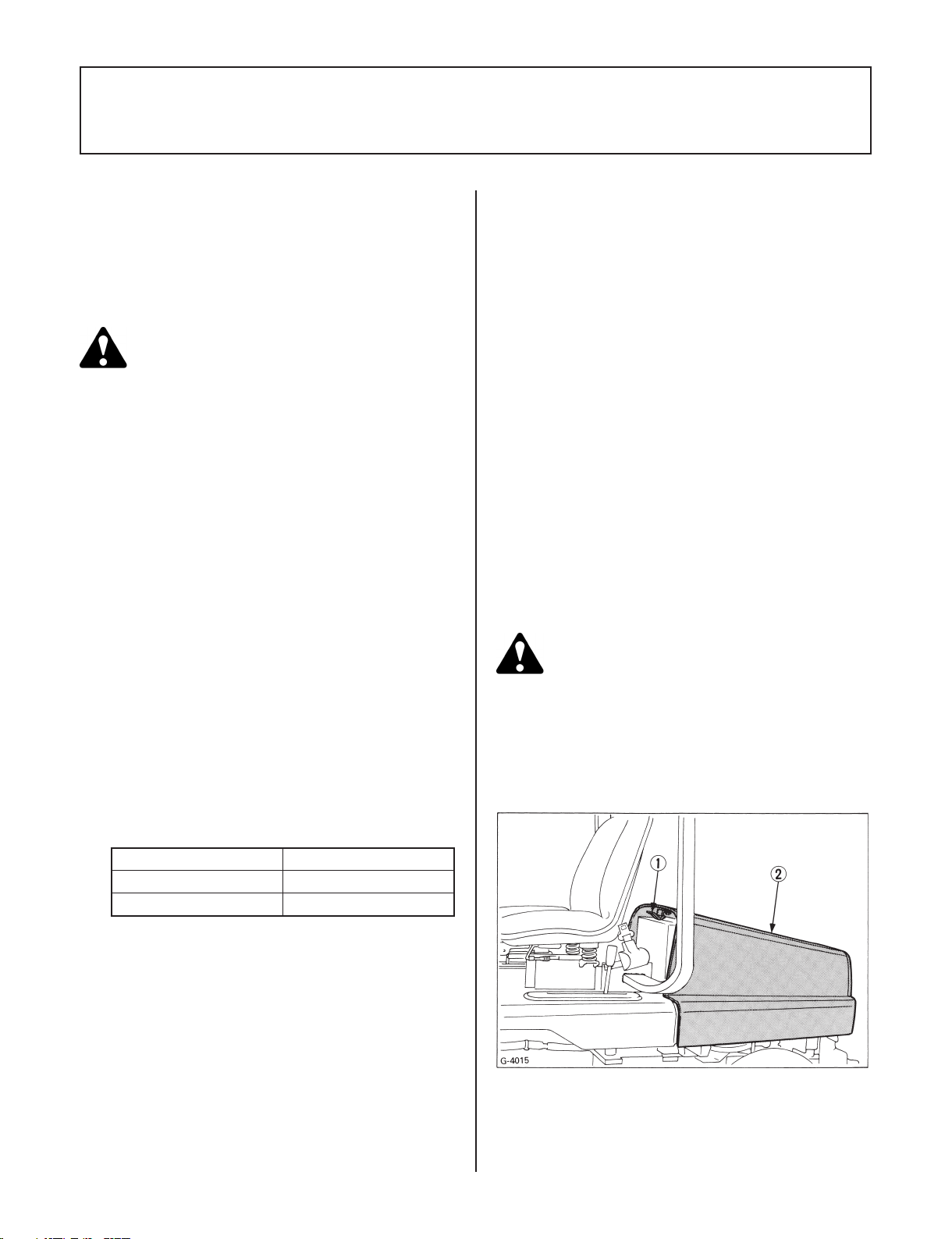
6.8 INTAKE AIR LINE
Checking Intake Air Line
■
WARNING
To avoid serious injury or death:
Before checking the intake air line, be sure to ●
stop the engine.
(1) Knuckle arm (4WD) (Grease)
(1) Check to see that hoses and hose clamps are tight and
not damaged.
Page 35

31
(2) If hoses and clamps are found worn or damaged, replace
or repair them at once.
(1) Hose
(2) Hose clamps
Replacing Intake Air Line
■
Consult your local KUBOTA Dealer for this service.
6.9 RADIATOR
Checking, Flush Cooling System and
■
Changing Coolant
(1) Check the coolant level should be between the Low and
High mark. If the level is below the Low mark, remove
the recovery tank cap, and add clean water and antifreeze.
IMPORTANT:
Do not start engine without coolant. ●
When mixing the anti-freeze with water, the anti-freeze ●
mixing ratio is 50 %.
Use clean, fresh water and anti-freeze to ll the radiator ●
and recovery tank.
Securely tighten the radiator cap and recovery tank cap. ●
(2) If the engine is stopped by over-load during operation, in
order for coolant to return from the recovery tank to the
radiator, keep the engine rpm idle a little while.
(3) Remove the radiator pressure cap and check to see
that the coolant level is just below the port. If short, add
coolant.
(4) To drain the used coolant, open the drain valves and
remove radiator cap. The radiator cap must be removed
to completely drain the radiator.
WARNING
To avoid serious injury or death:
Do not remove radiator ll cap until coolant ●
temperature is well below its boiling point.
Then loosen cap slightly to the stop to relieve
any excess pressure before removing cap
completely.
WARNING
To avoid serious injury or death:
Before checking the radiator, be sure to stop the ●
engine.
(1) Drain valve
(1) Radiator cap
(2) Over ow pipe
(3) Recovery tank
(4) Recovery tank cap
(A) "HIGHEST LEVEL"
(B) "LOWEST LEVEL"
(1) Drain valve
(5) After all coolant is drained, install the drain valve.
Page 36

32
(6) Fill with clean water and cooling system cleaner.
(7) Follow directions of the cleaner instruction.
(8) After ushing, ll with clean water and anti-freeze
until the coolant level is just below the ll port on the
radiator.
(9) Be sure to close the radiator cap securely. If the cap is
loose or improperly closed, water may leak out and the
engine could overheat.
(10) The Radiator should be lled with part anti-freeze
and part water at all times as recommended by the
anti-freeze manufacturer. The anti-freeze contains
a corrosion inhibitor and will allow a higher operating
temperature in the radiator during the hot season.
(11) Do not use an anti-freeze and scale inhibitor at the same
time.
Checking Radiator Hoses (Water Pipes)
■
(1) If clamp bands are loose or water leaks, tighten bands
securely.
(2) Replace hoses and tighten clamp bands securely, if
radiator hoses are swollen, hardened or cracked.
Replace hoses and clamp bands if you checked and
found that hoses are swollen, hardened or cracked.
Anti-freeze
■
WARNING
To avoid serious injury or death:
When using anti-freeze, put on some protection ●
such as rubber gloves (Anti-freeze contains
poison.).
If it is swallowed, seek immediate medical help. ●
Do NOT make a person throw up unless told
to do so by poison control or a health care
professional.Usestandard rstaidand CPRfor
signs of shock or cardiac arrest. Call your local
Poison Control Center or your local emergency
number for further assistance.
When anti-freeze comes in contact with the skin ●
or clothing, wash it off immediately.
Do not mix different types of Anti-freeze. The ●
mixture can produce chemical reaction causing
harmful substances.
Anti-freezeisextremelyammableandexplosive ●
undercertainconditions.Keepreand children
away from anti-freeze.
When draining uids from the engine, place ●
some container underneath the engine body.
Do not pour waste onto the grounds, down a ●
drain, or into any water source.
Also, observe the relevant environmental ●
protection regulations when disposing of antifreeze.
(1) Radiator hose
Precaution at Overheating
■
Take the following actions in the event the coolant temperature
be nearly or more than the boiling point, what is called
"Overheating".
(1) Stop the machine operation in a safe place and keep the
engine unloaded idling.
(2) Don't stop the engine suddenly, but stop it after about 5
minutes of unloaded idling.
(3) Keep yourself well away from the machine for further 10
minutes or while the steam blown out.
(4) Checking that there gets no danger such as burn, get rid
of the causes of overheating according to the manual,
see "Troubleshooting" section. And then, start again the
engine.
Always use a 50/50 mix of long-life coolant and clean soft
water in KUBOTA engines.
Consult your local KUBOTA dealer concerning coolant for
extreme conditions.
(1) Long-life coolant (hereafter LLC) comes in several
types. Use ethylene glycol (EG) type for this engine.
(2) Before employing LLC-mixed cooling water, ll the
radiator with fresh water and empty it again. Repeat this
procedure 2 or 3 times to clean up the inside.
(3) Mixing the LLC
Premix 50% LLC with 50% clean soft water. When
mixing, stir it up well, and then ll into the radiator.
(4) The procedure for the mixing of water and anti-freeze
differs according to the make of the anti-freeze and the
ambient temperature. Refer to SAE J1034 standard,
more specically also to SAE J814c.
IMPORTANT:
When mixing the anti-freeze with water, the anti-freeze ●
mixing ratio is 50 %.
Vol %
Anti-freeze
50 -37 -34 108 226
* At 1.013 x 10
A higher boiling point is obtained by using a radiator
Freezing Point Boiling Point *
°C °F °C °F
5
Pa (760 mmHg) pressure (atmospheric).
Page 37

33
pressure cap which permits the development of pressure
within the cooling system.
(5) Adding the LLC
1. Add only water if the mixture reduces in amount by
evaporation.
2. If there is a mixture leak, add the LLC of the
same manufacturer and type in the same mixture
percentage.
*Never add any long-life coolant of different
manufacturer. (Different brands may have different
additive components, and the engine may fail to
perform as specied.)
(6) When the LLC is mixed, do not employ any radiator
cleaning agent. The LLC contains anti-corrosive agent.
If mixed with the cleaning agent, sludge may build up,
adversely affecting the engine parts.
(7) KUBOTA's genuine long-life coolant has a service life
of 2 years. Be sure to change the coolant every 2000
hours or every 2 years whichever comes faster.
NOTE:
The above data represent industry standards that ●
necessitate a minimum glycol content in the concentrated
anti-freeze.
Checking and Cleaning Radiator to
■
Prevent Overheating
Daily or after every 5 hours of operation, check to be sure
the radiator screen and radiator core are clean. Dirt or chaff
on the radiator screen or radiator core decrease cooling
performance.
(1) Remove the radiator screen and panel screen, and
remove all foreign material.
(2) Remove the dust from between the ns and the tube.
(3) Tighten the fan drive belt as necessary. For this, refer to
page 38.
(4) If scale forms in the tube, clean with the scale inhibitor
or its equivalent.
(5) Each time the panel screen is covered with grass during
operation, rub it off the screen with hand. Check the
radiator screen from time to time if grass often gets on
it.
(6) If the dust or chaff is accumulated inside of the panel,
remove the air intake screen and clean the inside of the
panel completely.
After cleaning, place the air intake screen properly.
IMPORTANT:
Be sure to stop the engine before cleaning the radiator ●
screen and panel screen.
(1) Panel screen
(2) Radiator screen
6.10 AIR CLEANER
WARNING
To avoid serious injury or death:
Before checking, be sure to stop the engine. ●
(1) The air cleaner uses a dry element, never apply oil.
(2) Do not touch the lter element except where cleaning
is required. To clean the element, use clean and dry
compressed air on the inside of the element. Air pressure
should not exceed 205 kPa (2.1 kgf/cm
(3) If the element is stained with carbon or oil, apply one of
the following cleaners or equivalent.
ND-1400 (by Donaldson)
(4) When cleaning the air lter element, do not remove the
cyclone from the air lter element, handle with care not
to damage it (do not hit it), and reinstall the element
correctly.
The damage of the element may cause serious trouble
to the engine.
2
, 30 psi).
Page 38

34
(5) Replace the air cleaner element every 1000 hours or
every 1 year whichever comes faster.
(1) Air cleaner
(2) Air cleaner element
(3) Air cleaner band
6.11 BATTERY
DANGER
To avoid the possibility of battery explosion: For
the rellable type battery, follow the instructions
below.
Do not use or charge the rellable type battery ●
ifthe uidlevel isbelow theLOWER(lowerlimit
level) mark. Otherwise, the battery component
parts may prematurely deteriorate, which may
shorten the battery's service life or cause an
explosion. Check the uid level regularly and
add distilled water as required so that the uid
level is between the UPPER and LOWER levels.
Mishandling the battery shortens the service life and adds to
maintenance costs. Be sure to handle it correctly so that it will
develop its full potential performance.
(1) Battery
(2) Positive cable (
(3) Negative cable (
If the battery is weak, the engine is difcult to start and the
lights become dim. It is important to check the battery daily
and recharge before trouble occurs.
Battery Charging
■
)
)
DANGER
To avoid serious injury or death:
When the battery is being activated, hydrogen ●
and oxygen gases in the battery are extremely
explosive. Keep open sparks and ames away
from the battery at all times, especially when
charging the battery.
WARNING
To avoid serious injury or death:
Never take the battery cap off while the engine is ●
running.
Keep electrolyte away from eyes, hands and ●
clothes. If you are spattered with it, wash it away
completely with water immediately.
(1) Make sure each electrolyte level is somewhere between
the markings (A) and (B). Add a proper amount of
distilled water up to the highest level as required.
(2) The water in the electrolyte evaporates during
recharging. Liquid shortage damages the battery and
excessive liquid damages the machine body. If low, be
sure to ll up the battery with distilled water only.
(A) "HIGHEST LEVEL" (B) "LOWEST LEVEL"
Page 39

35
(3) To slow charge the battery connect the battery positive
terminal to the charger positive terminal and the negative
to the negative, then recharge in the standard fashion.
(4) A boost charge is only for emergencies. It will partially
charge the battery at a higher rate and in a short time.
When using a boost-charged battery, it is necessary to
recharge the battery as early as possible. Failure to do
this extremely affects its service life.
DANGER
To avoid serious injury or death:
When connecting the battery, do not reverse the ●
polarities. Connection with reverse polarities
will cause spark and troubles to the battery and
electrical system in the tractor.
When disconnecting the cable from the battery, ●
start with the negative terminal rst. When
connecting,startwiththepositive terminal rst.
Reversing the steps may cause short-circuiting,
should a metallic tool touch the terminals.
Direction for Storage
■
(1) When storage the machine for long periods of time,
remove the battery from the machine, adjust the
electrolyte to the proper level by adding distilled water
only and store in a dry place out of direct sunlight.
(2) The battery self-discharges even while it is stored.
Recharge it once a month in hot seasons and once
every two months in cold seasons.
(3) Nut size for the battery terminals: (+)10 mm (-)10 mm.
6.12 TIRE PRESSURE
WARNING
To avoid serious injury or death:
Do not attempt to mount a tire on a rim. This ●
should be done by a qualied person with the
proper equipment.
Always maintain the correct tire pressure. Do not ●
inate tires above the recommended pressure
shown in the Operator's Manual.
Though the tire pressure is factory-set to the recommended
level, it naturally drops slowly in the course of time. Thus,
check it every day and inate as necessary.
Maximum tire pressures
Front Rear
22 psi 24 psi
(1) Ground (A) "INSUFFICIENT"
(B) "STANDARD"
(C) "EXCESSIVE"
6.13 FUSE
The machine electrical system is protected from potential
damage by fuses.
A blown fuse indicates that there is an overload or short
somewhere in the electrical system.
IMPORTANT:
Before replacing a blown fuse, determine why ●
the fuse blew and make any necessary repairs.
Failure to follow this procedure may result in
serious damage to the machine electrical system.
Refer to the "TROUBLESHOOTING" section of this
manual or your local KUBOTA Dealer for specic
information dealing with electrical problems.
If any of the fuses should blow, replace with a new one of
the same capacity. Do not use the fuse except indicated
capacity.
IMPORTANT:
Do not use tires other than those approved by KUBOTA. ●
WARNING
To avoid serious injury or death:
Never operate the machine with a loose rim, ●
wheel, or axle.
Whenever bolts are loosened, retighten to ●
speciedtorque.
Check all bolts frequently and keep them ●
tightened.
Page 40

36
Replacement of the fuse.
(1) Open the fender cover.
(2) Remove the lid of the fuse box.
(3) Disconnect the blown fuse.
(4) Place a new fuse of same capacity in position.
(5) Close the fender cover.
(1) Fuse box
IMPORTANT:
If the new fuse happens to quickly blowout, contact your ●
dealer for inspection and repair. Never use any wire or
foil.
6.14 CHECKING ENGINE START SYSTEM
The Engine Start System in your machine are designed to
protect you while operating. Please check these Engine Start
System periodically. It is recommended to check the Engine
Start System before daily operation.
WARNING
To avoid serious injury or death:
Do not allow anyone near the machine while ●
testing.
If the machine does not pass one of the following ●
tests, do not operate the machine. See your local
KUBOTA Dealer.
Check while seated. ●
Safety switch
♦
Test 1: Switch for the PTO lever
(1) Depress the brake pedal fully.
(2) Shift the PTO lever to engaged position.
(3) Turn the key to START position.
(4) The engine must not crank.
Test 2: Switch for the brake pedal
(1) Disengaged PTO lever.
(2) Release the brake pedal.
(3) Turn the key to START position.
(4) The engine must not crank.
Fusible link
■
The fusible link is intended to protect the wiring. If the link
breaks down, pinpoint the cause. Be sure to use the genuine
part, not any substitute.
(1) Fusible link
6.15 CHECKING OPC SYSTEM
The OPC (Operator Presence Control) system in your
machine are designed to protect you while operating.
Please check these OPC system periodically. It is
recommended to check the OPC system before daily
operation.
WARNING
To avoid serious injury or death:
Do not allow anyone near the machine while ●
testing.
If the machine does not pass one of the following ●
tests, do not operate the machine. See your local
KUBOTA Dealer.
Sit on the operator's seat for all tests. ●
1. Check the following tests before operating the
machine.
2. If the machine does not pass one of the following tests,
do not operate the machine. See your local KUBOTA
Dealer.
Test 1: Switch for the operator's seat (OPC)
(1) Lock the parking brake.
(2) "START" the engine.
(3) Release the parking brake and stand up from the
operator's seat. (Do not get off the machine.)
Page 41

37
(4) Make sure that the engine "STOPS".
Test 2: Switch for the operator's seat (OPC)
(1) Run the engine at half throttle.
(2) Engaged the PTO clutch lever.
(3) Stand up. (Do not get off the machine.)
(4) Engine must shut off.
6.16 REPLACING LIGHT BULB
1. Head light
Take the bulb out of the light body and replace with a
new one.
2. Other lights
Detach the lens and replace the bulb.
Light Capacity
Headlight 15 W
Page 42

38
7. ADJUSTMENTS
7.2 BRAKE
WARNING
To avoid serious injury or death:
When making adjustments, park the machine on ●
a level surface, apply the parking brake and stop
the engine and remove the key.
7.1 FAN DRIVE BELT TENSION
If the fan drive belt becomes loose, the engine may overheat.
To adjust, loosen bolts and turn the dynamo to stretch the
belt. After adjustment, securely tighten the bolts.
Moderate belt tension:
The belt should deect approx. 10 mm (0.4 in.) when the
center of the belt is depressed with nger pressure of 98 N
(10 kgf, 22 Ibs).
■
(1) The pedal free travel S1 to the beginning of brake
(2) If the free travel S1 is not correct, loosen the lock nut (2)
(3) After adjustment, securely retighten the lock nut.
Check and Adjustment of the Brake Pedal
engaged should be from 10 to 50 mm (0.4 to 2.0 in.) for
2WD, from 20 to 60 mm (0.8 to 2.3 in.) for 4WD.
and turn the nut (3) until the proper stroke is achieved.
(1) Cap
(2) Tension bolt
(3) Dynamo
(4) Adjusting bolt
IMPORTANT:
When replacing fan drive belt, be careful not to catch it on ●
the cap under the water pump. See the illustration above.
(A) 10 mm (0.4 in.)
(1) Brake pedal
(2) Lock nuts
(5) Bolt (6) Stopper (7) Speed set lever
Check the Speed Set Device Release
■
The brake pedal stroke concerns with the speed set device.
(1) Check the speed set device works and release
automatically when the brake pedal is depressed fully.
(2) If not, loosen the bolt (5) and slide the stopper (6) to the
proper position.
(3) Nut
(4) Spring
Page 43

7.3 REAR AXLE (2WD)
Check and Adjustment of the Rear Axle
■
End Play
(1) Jack up the rear of frame.
(2) Measure the clearance (l) between the rear axle (3) and
rear axle support (5).
(3) If the measurement exceeds the allowable limit, adjust
the nut (1).
(1) Nut
(2) Spring lock pin
(3) Rear axle
(4) Center pin
(5) Rear axle support
39
(1) Nut
(2) Spring lock pin
(3) Rear axle
(4) Center pin
(5) Rear axle support
(l) Rear axle end play
NOTE:
When fastening the center pin (4), rst tighten the nut (1) ●
until the rear axle can turn smoothly, then loosen the nut
the nearest pin hole is reached, and nally put the spring
lock pin in position.
Rear axle end play
(l)
Factory spec. 0.1 to 0.4 mm
Allowable limit 1.0 mm
Page 44

40
8. TROUBLESHOOTING
8.1 BATTERY TROUBLESHOOTING
Trouble Cause Remedy Preventive measure
Starter does not function. Battery overused until
From beginning starter does
not function, and lights soon
become dim.
When viewed from top, the
top of plates looks whitish.
Recharging is impossible. Battery life expired.
Terminals are severely
corroded and heat up.
Battery electrolyte level drops
rapidly.
If you have any questions, contact your KUBOTA dealer.
•
lights are dim.
Battery has not been
•
recharged.
Poor terminal connection.
•
Battery life expired.
•
Insufcient charging.
•
Battery was used with
•
an insufcient amount of
electrolyte.
Battery was used too much
•
without recharging.
•
Poor terminal connection.
•
There is a crack or pin holes
•
in the electrolytic cells.
Charge battery sufciently.
•
Clean the terminal and
•
tighten securely.
Renew battery.
•
Charge battery sufciently.
•
Add distilled water and
•
charge the battery.
Charge battery sufciently.
•
Replace battery.
•
Clean the terminal and
•
tighten securely.
Replace battery.
•
Charge the battery
•
properly.
Keep the terminal
•
clean and tight.
Apply grease and treat with
anti-corrosives.
Battery must be seviced
•
properIy before initial use.
Regularly check the
•
electrolyte level.
Charge the battery
•
properly.
Keep the terminal
•
clean and tight.
Apply grease and treat with
anti-corrosives.
8.2 MACHINE TROUBLESHOOTING
Trouble Cause Remedy
Machine operation is not smooth. Hydrostatic transmission uid is
Machine does not move while engine is
running.
Machine moves when speed control
pedal is not depressed. (Engine is
operated.)
If you have any questions, contact your KUBOTA dealer.
•
insufcient.
Filter is clogged.
•
Strainer is clogged.
•
Parking brake is on.
•
Transmission uid level is insufcient.
•
Hydrostatic lever linkage is not
•
correctly adjusted.
Replenish oil.
•
Replace the lter.
•
Clean the strainer.
•
Release the parking brake.
•
Replenish oil.
•
Ask your dealer for hydrostatic lever
•
linkage adjustment or pressure
adjustment.
Page 45

8.3 ENGINE TROUBLESHOOTING
If the engine is not performing correctly, refer to the table below for the cause and its corrective measure.
Trouble Cause Remedy
Engine is difcult to start. No fuel ow.
Insufcient engine power. Insufcient fuel.
Engine stops suddenly. Insufcient fuel.
Exhaust fumes are colored. Fuel quality is poor.
Engine Overheats. Engine overloaded.
If you have any questions, contact your KUBOTA dealer.
•
Air and water is in the fuel system.
•
In winter, oil viscosity increases, and engine
•
cranks slow.
Battery is discharged and the engine will not
•
crank.
•
The air cleaner is clogged.
•
•
•
•
Low coolant level.
•
Loose or damaged fan belt.
•
Dirty radiator core or grille screens.
•
Coolant ow route corroded.
•
Check the fuel tank and the fuel lter, and
•
remove dirt build-up.
Replace lter if necessary.
•
Check to see if the fuel lines are tight. Bleed
•
the fuel system. (see page 24)
Use oils of different viscosities, depending
•
on ambient temperatures.
Charge the battery.
•
In cold weather, always remove the battery,
•
charge it and store it indoors. Install it only
when the machine is going to be used.
Check the fuel system.
•
Clean the element.
•
Refuel.
•
Bleed the fuel system.
•
Change the fuel.
•
Lower speed or reduce load.
•
Fill cooling system to proper level; check
•
radiator and hoses for loose connections or
leaks.
Adjust fan belt.
•
Remove all trash.
•
Flush cooling system.
•
41
Page 46

42
9. LONG-TERM STORAGE
STORING AND HANDLING FUEL
WARNING
To avoid serious injury or death:
To reduce re hazards, allow the engine and ●
exhaust system to cool before storing the vehicle
in an enclosed space or near combustible
materials.
Do not operate the engine in a closed room. ●
The air will be polluted with exhaust gas which is
very dangerous.
Do not clean the machine with engine running. ●
When storing, remove the key from the key ●
switch to avoid unauthorized persons from
operating the machine and getting injured.
When the machine is not going to be operated for two or
three months or longer, clean the machine and perform the
following operations before storage.
(1) Repair the parts where needed.
(2) Check bolts and nuts, tighten as necessary.
(3) Apply grease or engine oil to parts most likely to rust.
(4) Inate the tires to a little above the standard pressure
levels.
(5) Change the engine oil and run the machine for ve
minutes so that the oil circulates through the entire
system.
(6) Drain fuel tank and run engine to eliminate fuel from the
lines.
(7) Drain the cooling system.
(8) Lower the implement to the ground.
(9) Remove the battery from the machine, recharge it,
adjust the electrolyte to the proper level, and store in a
dry place out of direct sunlight.
(10) The battery runs down over time even while in storage.
Recharge it once a month in hot seasons and once
every two months in cold seasons.
(11) Store the machine where it is dry and sheltered from
rain. Further cover the machine with a tarpaulin.
(12) When leaving the machine outdoors, protect the mufer
opening from rain.
(1) Buy clean, high quality fuel from a reliable supplier.
IMPORTANT:
Keep dirt, scale, water or other foreign material out of ●
fuel.
(2) Keep fuel in a clean container in a protected area away
(3) Drain water and sediment from storage tank regularly.
(4) Keep storage tank on its side with plug up.
(5) Avoid storing fuel for a long time. If you keep fuel for
IMPORTANT:
Remove the mower deck shield and clean all debris off ●
deck. Paint any surfaces that have exposed metal.
from buildings.
a long time, add a fuel conditioner to prevent water
condensation and varnish. See your KUBOTA dealer for
conditioner.
Page 47

43
10. WIRING DIAGRAM
Page 48

Page 49

Page 50

Page 51

3
SAFETY FIRST
IMPORTANT :
NOTE :
3
DANGER :
3
WARNING :
3
CAUTION :
Indicates an imminently hazardous situation which, if not
avoided, will result in death or serious injury.
Indicates a potentially hazardous situation which, if not
avoided, could result in death or serious injury.
Indicates a potentially hazardous situation which, if not
avoided, could result in minor or moderate injury.
Indicates that equipment or property damage could result if
instructions are not followed.
Gives helpful information.
This symbol, the industry's ''Safety Alert Symbol'', is used throughout this manual
and on labels on the machine itself to warn of the possibility of personal injury.
Read these instructions carefully. It is essential that you read the instructions and
safety regulations before you attempt to assemble or use this unit.
FOREWORD
You are now the proud owner of a KUBOTA RC48-F19, RC54-F19, RC60-F19
ROTARY MOWER. This rotary mower is a product of KUBOTA's quality engineering
and manufacturing. It is made of excellent materials and under a rigid quality control
system. It will give you long, satisfactory service. To obtain the best use of your
machine, please read this manual carefully. It will help you become familiar with the
operation of the machine and contains many helpful hints about machine
maintenance. It is KUBOTA's policy to utilize, as quickly as possible, every advance
in our research. The immediate use of new techniques in the manufacturing of
products may cause some small parts of this manual to become outdated. KUBOTA
distributors and dealers will have the most up-to-date information. Please do not
hesitate to consult them.
Page 52

SAFE OPERATION ........................................................1
1. SERVICE.........................................................................3
2. INTRODUCTION .............................................................3
2.1 SPECIFICATIONS ...................................................3
2.2 MOWER DECK TERMINOLOGY ............................4
3. SETTING UP ...................................................................5
3.1 PRE-ASSEMBLY .....................................................5
3.2 SETTING UP THE MOWER ...................................5
4. MOUNTING AND DISMOUNTING THE MOWER ..........7
5. OPERATION ...................................................................8
5.1 MAKING THE MOST OF YOUR MOWER ..............8
5.2 CUTTING HEIGHT ..................................................8
5.3 OPERATING MOWER ............................................9
6. MAINTENANCE ............................................................10
6.1 MAINTENANCE CHECK LIST ..............................10
6.2 CHECK AND MAINTENANCE ..............................10
6.3 BLADE REPLACEMENT .......................................11
6.4 BELT REPLACEMENT ..........................................13
6.5 ADJUSTING THE LIFT RODS ..............................13
6.6 FRONT GAUGE WHEEL ......................................13
6.7 ADJUSTING THE LIFT SPRINGS (2WD) .............14
6.8 TIGHTENING TORQUE CHART ...........................14
7. TROUBLESHOOTING ..................................................15
Page 53

SAFE OPERATION
Careful operation is your best insurance against an accident. Read this section carefully before operating the mower. All operators,
no matter how much experience they may have had, should read this and other related manuals before operating mower. It is the
owner's obligation to instruct all operators in safe operation.
1
1. Keep bystanders at a safe distance from the machine
during mowing operations.
2. Prior to mowing operations, clear area to be mowed of
all objects which might be picked up and thrown by the
mower. Mow only in daylight or in good articial light.
3. Do not wear loose clothing while operating the mower.
Loose clothing could become entangled in moving
parts, causing personal injury.
4. Do not stand on the mower.
5. Before dismounting the front mower.
a) Shut off the engine,
b) remove the key,
c) set the parking brake,
d) allow the blades to stop.
6. Securely tighten all hardware before operating the
mower.
7. Read this manual and the front mower operator's
manual before operating mower. Allow only a properly
trained person to operate the front mower.
8. Before starting the engine, disengage the FRONT PTO
and shift the front mower transmission into neutral.
9. Hillside operation is dangerous and is not
recommended.
If it is necessary to mow on a hillside, use extreme
caution. Never mow across the face of a slope.
10. While making turns in rough terrain, reduce front mower
speed.
11. Upon striking a foreign object, stop and inspect the front
mower and the mower for damage.
Repair the damage before resuming equipment
operation.
12. If the mower discharge deector becomes clogged, stop
the front mower; disengage the mower drive; shut off the
engine and remove the key, and clean out the deector
before continuing.
13. Know how to stop the mower and engine quickly.
Be prepared for any emergency situation.
14. When mowing in rough terrain or in high grass, set the
mower at the highest cutting level to reduce the possibility
of the mower striking debris or hidden objects.
15. Before operating the front mower in reverse, look to see
if the area is clear of all objects.
16. Do not operate the mower without all shields, guards
and ROPS in place.
17. KUBOTA recommends the use of ROPS and seat belt in
almost all applications.
Always use seat belt when the front mower is equipped
with a ROPS.
Never use the seat belt when the front mower is not
equipped with a ROPS.
18. Never attempt to make adjustment or repairs of any
kind while the front mower and mower are running. Shut
off the engine, remove the key and allow the blades to
stop.
19. Replace damaged or illegible safety decals.
See next page for required labels.
Page 54

2
MOWER SAFETY LABELS
CARE OF SAFETY LABELS
(1) Keep safety labels clean and free from obstructing material.
(2) Clean safety labels with soap and water, dry with a soft cloth.
(3) Replace damaged or missing safety labels with new labels from your KUBOTA dealer.
(4) If component(s) with safety label(s) afxed is (are) replaced with new part(s), make sure new safety label(s) is (are) attached
in the same location(s) as the replaced components.
(5) Mount new safety labels by applying on clean, dry surface and pressing any bubbles to outside edge.
Page 55

1. SERVICE
(1) When in need of parts or of service, give the serial
number of the Mower to the dealer.
(2) The serial number is located on the right side of the
deck.
(3) For your reference, please record the serial number in
the space provided.
KUBOTA MOWER
MODEL ..................................................................................
SERIAL NUMBER .................................................................
DATE OF PURCHASE ..........................................................
NAME OF DEALER ...............................................................
3
(1) Serial number
2. INTRODUCTION
2.1 SPECIFICATIONS
Model RC48-F19 RC54-F19 RC60-F19
Mounting method 2 point linkage
Adjustment of cutting height Gauge wheel
Cutting width mm (in.) 1224 (48) 1372 (54) 1524 (60)
Cutting height mm (in.) 25 to 102 (1.0 to 4.0)
Weight (Approx.) kg (lbs.) 95 (209) 112 (247) 125 (275)
Blade spindle speed rpm (r/s) 3646 (60.8) 3255 (54.2) 2929 (48.8)
Blade tip velocity fpm (m/s) 15930 (80.9) 15930 (80.9) 15790 (80.2)
Blade length mm (in.) 424 (16.7) 475 (18.7) 523 (20.6)
Number of blades 3
Total length mm (in.) 770 (30.3) 805 (31.7) 858 (33.8)
Dimensions
Total width mm (in.) 1535 (60.4) 1737 (68.4) 1864 (73.4)
Total height mm (in.) 407 (16.0)
Page 56

4
2.2 MOWER DECK TERMINOLOGY
Page 57

3. SETTING UP
5
When the RC48-F19, RC54-F19, RC60-F19 are shipped,
some of the parts are removed and packed separately. Read
the following procedure to properly assemble the mower.
3.1 PRE-ASSEMBLY
Take out all mower components from the case and check the
parts by the illustration.
3.2 SETTING UP THE MOWER
(1) Attach both gauge wheel arms and center frame to the
deck with M10 bolts, spring washers, at washers and
nuts.
(1) 8-M10 x 28 bolts, Spring washers, Flat washers and
nuts
(2) 4-M10 x 25 bolts
(2) Attach the front gauge wheels to the arms with clevis
pins and snap rings.
(1) Front gauge wheel
(2) Gauge wheel arm
(3) Clevis pin
10 x 55, Snap ring
Page 58

6
(3) Attach the front anti-scalp roller and brackets to the deck
with M10 bolts.
(1) Deck
(2) Bracket
(4) Attach the discharge deector, deector stopper and
spacers (RC48 only) to the deck with M10 bolts, spring
washers and nuts. Secure the spring to the discharge
deector as illustrated.
NOTE:
Be sure to direct the deector stopper as shown. ●
(3) Scalp roller
(4) 4-M10 x 25 bolts
(5) Attach the anti-scalp roller with roller pin, plain washer
and cotter pin at hole (A).
(1) Anti-scalp roller
(2) Roller pin, Plain washer, Cotter pin
(A) Hole
(B) Hole
(1) Discharge deector
(2) Bolt (3-M10 x 25)
(3) Spacer (RC48 only)
(4) Spring washer
(5) Nut
(6) Bolt
RC48: M10 x 35
RC54, 60: M10 x 28
(7) Deector stopper
(8) Spring
Page 59

4.
MOUNTING AND DISMOUNTING THE MOWER
7
(1) Push the mower deck under the mower links.
WARNING
To avoid serious injury or death:
The mower links (left hand, right hand) are ●
spring-loaded. Have an assistant hold the arm
in position when mounting mower deck.
(1) Mower link
(2) Set pin, Clevis pin
(5) Pull back coupler of the universal joint.
Push the universal joint onto the PTO shaft until the
coupler locks.
Slide the universal joint back and forward to make sure
the universal joint is locked securely.
(1) Coupler
(2) Yoke
IMPORTANT:
Finally pull the universal joint to see if it is tight in position. ●
(2) Attach the front end of the mower links to the mower
deck with clevis pins and hairpins.
(3) Start engine, raise implement, and shut off the engine.
(4) Install the lift rods to the mower deck with lock pins.
(1) Set pin
(2) Clevis pin
(3) Mower deck
(4) Lift rod
(5) Lock pin
(6) Mower link
(6) To dismount the mower, reverse the above procedure.
Page 60

8
5. OPERATION
5.1 MAKING THE MOST OF YOUR
MOWER
(1) When using your mower for the rst time, choose
a smooth level area and cut in straight and slightly
overlapping strips.
(2) The size and type of the area to be mowed will
determine the proper mowing pattern. Take into account
obstructions, such as trees, fences and buildings. To
keep grass cuttings off fences, sidewalks, etc., it is
advisable to go over the outside of the area to be mowed
several times in a clockwise direction. To mow the area
remaining, work in a counterclockwise direction so the
cuttings are dispersed onto the previously cut area.
(3) Always keep the left side of the mower toward trees,
posts or other obstacles on the rst trip around the
obstacle.
(4) Most lawns should be mowed to keep the grass
approximately 50 to 80 mm (2 to 3 in.) high. Best results
are obtained by cutting often and not too short. To keep
a green lawn, never mow more than one third of the
height of the grass or a maximum of 25 mm (1 in.) in one
mowing.
For extremely tall grass, set the cutting height at
maximum height for the rst mowing, then reset to the
desired height and mow again. Allow the grass to grow
to 8 cm (3 in.), then cut off only the top inch.
(5) On thick, springy grass or soft ground, the mower rollers
may sink into ground giving too low a cut.
Adjust the cutting height to get the desired height of
cut.
(6) For best appearance, grass should be cut in the
afternoon or evening when it is free of moisture.
5.2 CUTTING HEIGHT
DANGER
To avoid serious injury or death:
Never operate mower in transport position. ●
(1) Check the both front gauge wheel pressures daily and
inate as necessary to prevent uneven cutting height.
(See page 13)
(2) To set the cutting height, adjust the front gauge wheels,
lift rods. Cutting height can be adjusted from 25 to 102
mm (1.0 to 4 in.).
NOTE:
For easy adjusting of the lift rods, place a wooden block ●
under the rear end of the mower deck before lowering the
mower deck.
Cutting height will change because of the ground ●
condition.
(3) Lower the mower deck by pushing the hydraulic control
lever forward. This lowers the mower deck from the
transport position to the operating position.
(4) Use the higher setting for mowing in a rough area or
when mowing high grass. Lower setting should be used
only for smooth lawns where short grass is desired.
Page 61

5.3 OPERATING MOWER
DANGER
To avoid serious injury or death:
Do not operate the mower without discharge ●
deectorproperlyboltedinplace.
WARNING
To avoid serious injury or death:
Clear the work area of objects which might be ●
picked up and thrown.
Do not direct the opening of the deector at ●
bystanders or animals. Ejected objects may
cause injury. Plan your mowing carefully before
starting operations.
Keep bystanders and animals away from the ●
mowing area.
Be sure to disengage the front PTO clutch of ●
the mower before starting the engine.
9
(1) Keep the engine running at full throttle for best results.
Control travel speed by speed control pedal.
(2) During heavy duty use, operate the machine at a slower
ground speed or go over the area twice.
(3) Keep the mower deck and gauge wheels in the raised
position when the mower is not being used.
(4) The mower will not cut cleanly if the ground speed is too
high or if the blade speed drops due to an overload.
NOTE:
To prevent the engine from overheating, keep the ● radiator
and radiator net clean.
Page 62

10
6. MAINTENANCE
6.1 MAINTENANCE CHECK LIST
Used hours (Change or check every interval shown below)
No. Check Point
Anything unusual in previous
1
day's operation
2 Oil leakage check
Make sure blade cap screws
3
are tight.
4 Blade and belt wear check
5 All hardware check
6 Make sure all pins are in place.
7 Mower deck cleaning
8 Gear box oil check
9 Gear box oil change
Greasing
Front gauge wheel brackets
•
Three spindle shafts
•
10
11 Gear box oil seal check
12
IMPORTANT:
« Replace if any deterioration (crack, hardening, scar, or deformation) or damage occurred.
NOTE:
*1 The initial 50 hours should not be a replacement cycle.
Universal joint
•
Belt tension pivot and
•
tension pulley
Gear box oil seal replace
The jobs indicated by ●
must be done after the rst time at 50 hrs.
daily
check
¡
¡
¡
¡
¡
¡
¡
¡
¡
50 100 150 200 250 300 350 400
*1
¡ ¡ ¡ ¡ ¡ ¡ ¡ ¡
¡ ¡
1
year4 years
«
¡
Reference
After since
every 150 hrs. 10
every 50 hrs. 11
1 year —
4 years
page
—
10
11, 12
12, 13
—
—
—
10
11
—
6.2 CHECK AND MAINTENANCE
WARNING
To avoid serious injury or death:
Stop the engine, set the parking brake, and ●
remove the key.
Gear box oil
■
(1) To check the oil level, remove the check plug (bolt).
Place mower on level surface.
•
Loosen the check plug. Oil must seep from the
opening. If low add oil.
(Use SAE 90 gear oil)
0.4 L (0.42 qts.)... RC54, RC60
0.35 L (0.37 qts.)... RC48
(1) Drain plug (Bolt) (2) Inlet and check plug (Bolt)
IMPORTANT:
Do not exceed check plug level. ●
Page 63

11
Greasing
■
(Use multipurpose EP2 grease (NLGI
Grade No.2).)
(1) Universal joint.
(1) Grease ttings
(2) Front gauge wheel brackets.
(4) Belt tension pivot and tension pulley.
(1) Grease tting (Belt tension pulley)
(2) Grease tting (Belt tension pivot)
6.3 BLADE REPLACEMENT
WARNING
To avoid serious injury or death:
Be sure to stop the engine and remove the key. ●
Blades may be sharp. When you handle blades, ●
wear heavy gloves or wrap end of blade with a
rag.
(1) Front gauge wheel bracket
(2) Grease tting
(3) Three spindle shafts.
IMPORTANT:
The bolt (blade) has R.H. threads. Turn it ●
counterclockwise to loosen.
To prolong the service life of the blade, reposition its ●
sections as shown in the gure below.
Before checking or replacing the blade, wipe grass ●
and mud off the top and inside of the mower.
Especially clean up the inside of the belt cover, because
otherwise the belt life will be reduced.
(1) LH blade
(2) Center blade
(3) RH blade
(1) Grease tting
Page 64

12
The blade cutting edges should be kept sharp at all times.
Sharpen the cutting edges, if they resemble the blade in
gure (B). Replace the blades if they appear similar to the
blade as shown in gure (C).
(A) "NEW BLADE"
(B) "WORN BLADE"
(C) "CRACKED BLADE"
(1) Remove the mower from the vehicle and turn it over to
expose the blades.
(2) Wedge a block of wood between the blade and mower
housing or install box wrench over pulley nut to prevent
spindle from rotating while removing blade bolts, then
loosen the blade bolt as illustrated.
(4) To check the blade for balance, place a small rod through
the center hole. The blade should balance on this rod.
If the blade is not balanced, le the heavy side of the
blade until balance is achieved.
(5) Attach the blade as illustrated. (RC48-F19)
(1) Spindle holder
(2) Blade
(3) 2-Cup washers
(4) Friction washer
NOTE:
Make sure the cup washer is not attened out or worn, ●
causing blade to slip easily. Replace both cup washers
and friction washer if either is damaged.
(RC54-F19, RC60-F19)
Pass the spline boss through the blade and 2 cup
washers, and tighten the bolt.
(5) Plain washer
(6) Spring washer
(7) Bolt
(A) "Loosen"
WARNING
To avoid serious injury or death:
Wear heavy gloves when removing blades. ●
NOTE:
Use the proper metric size box or socket wrench to ●
tighten or loosen the blade mounting bolt.
(3) To sharpen the blades, clamp the blade securely in a
vise.
Use a large mill le and le along the original bevel until
sharp.
(1) Spindle holder
(2) Blade
IMPORTANT:
Tightening torque of the blade bolts. ●
Center blade
Outer blade
(3) 2-Cup washers
(4) Spline boss
RC48-F19 RC54-F19, RC60-F19
10 to 12 kgf-m
(72 to 87 ft-lbs)
12.6 to 15 kgf-m
(91 to 109 ft-Ibs)
(5) Bolt
10 to 12 kgf-m
(72 to 87 ft-lbs)
Page 65

13
6.4 BELT REPLACEMENT
(1) Remove the mower from the tractor.
(2) Remove the left and right hand shields from the mower
deck.
(3) Clean around the gear box.
(4) Remove the right hand bracket which mounts the gear
box to the mower deck.
(5) Remove the belt from the tension pulley. Slip the belt
over the top of the gear box.
(6) To install a new belt, reverse the above procedure.
NOTE:
Tighten bracket bolts securely. ●
6.5 ADJUSTING THE LIFT RODS
WARNING
To avoid serious injury or death:
Shut off the engine, set the parking brake, and ●
remove the key.
(1) Park the front mower and mower deck on level ground
and set the desired cutting height.
(2) Check whether the mower deck is level.
(3) If not, adjust the length of the lift rod so that the deck is
leveled.
(4) Tighten the lock nut securely.
(1) Tension pulley
(2) Belt
IMPORTANT:
To avoid the misalignment of the center spindle.
Before attaching the bolt, attach the right hand bracket ●
securely.
(3) Bracket (RH)
(4) Tension spring
(1) Lift rod
(2) Lock nut
6.6 FRONT GAUGE WHEEL
[TIRES]
WARNING
To avoid serious injury or death:
Never exceed the tire pressure shown below ●
(maximum limit) when attempting to seat a
bead. If beads have not been seated by the time
the pressure reaches maximum limit, deate
the assembly, reposition the tire on the rim,
relubricate,andreinate.Afterseatingthebead,
adjust ination pressure as recommended in
theinationpressurechart.
Maxinationpressure:3.8x10⁵ Pa
(55 psi, 3.8 kgf/cm
WARNING
To avoid serious injury or death:
Donot attempttomountatireunlessqualied. ●
Use proper equipment.
2
)
The tire pressure is factory-set to the correct level, however,
tire pressure will drop slowly in the course of time. Check tire
pressure daily and inate as necessary.
Page 66

14
6.7 ADJUSTING THE LIFT SPRINGS
(2WD)
In order to help improve traction, adjust the lift springs
according to the chart below.
RC48-F19 RC54-F19 RC60-F19
RH
A= — A=15 mm (0.6 in.) A=33 mm (1.3 in.)
LH
A=10 mm (0.4 in.) A=10 mm (0.4 in.) A=10 mm (0.4 in.)
6.8 TIGHTENING TORQUE CHART
Thread Size
d (mm)
M8 12 or 13
M10 14 or 17
M12 17 or 19
M14 19 or 22
NOTE:
Figure "7" on the top of the bolt indicates that the bolt is of special material. ●
Before tightening, check the gure on the top of bolt. ●
Hexa-Bolt
Head size
B (mm)
ft-lbs N-m kgf-m ft-lbs N-m kgf-m
13.0 to 15.2
(14.1 ± 1.1)
28.9 to 33.3
(31.1±2.2)
46.3 to 53.5
(49.9±3.6)
79.6 to 92.6
(86.1±6.5)
No mark 7T
17.8 to 20.6
(19.2±1.4)
39.3 to 45.1
(42.2±2.9)
62.8 to 72.6
(67.7±4.9)
107.9 to 125.5
(116.7±8.8)
1.9 to 2.1
(2.0±0.1)
4.0 to 4.6
(4.3±0.3)
6.4 to 7.4
(6.9±0.5)
11.0 to 12.8
(11.9±0.9)
17.5 to 20.3
(18.9±1.4)
35.4 to 41.2
(38.3±2.9)
57.1 to 66.5
(61.8±4.7)
91.1 to 108.5
(99.8±8.7)
23.5 to 27.5
(25.5±2.0)
48.1 to 55.9
(52.0±3.9)
77.6 to 90.2
(83.9±6.3)
123.6 to 147.0
(135.3±11.7)
2.4 to 2.8
(2.6±0.2)
4.9 to 5.7
(5.3±0.4)
8.0 to 9.2
(8.6±0.6)
12.6 to 15.0
(13.8±1.2)
Page 67

7. TROUBLESHOOTING
Any service item refer to operator's manual for proper maintenance procedure.
Trouble Cause Remedy
Discharge chute plugged. Grass too wet.
Streaking of grass uncut. Ground speed too fast.
Uneven cut. Mower deck not level.
Blades scalping grass. Cutting height too low.
Belt slipping. Mower deck plugged.
Excessive vibration. Debris on mower deck or in pulleys.
Mower loads down tractor. Engine r.p.m. too low.
•
Grass too long.
•
Cutting too low.
•
Engine r.p.m. too low.
•
Ground speed too fast.
•
•
Engine r.p.m. too low.
•
Grass too long.
•
Blades dull or damaged.
•
Debris in mower deck.
•
•
Ground speed too fast.
•
Blades dull.
•
Blades worn.
•
Low tire ination.
•
Gauge wheels not adjusted correctly.
•
Gauge wheels pressure not adjusted
•
correctly.
•
Turning speed too fast.
•
Ridges in terrain.
•
Rough or uneven terrain.
•
Gauge wheels not adjusted correctly.
•
Bent blade(s).
•
•
Debris in pulleys.
•
Worn belt.
•
•
Damaged drive belt.
•
Damaged pulleys.
•
Pulleys out of alignment.
•
Blades out of balance.
•
•
Ground speed too fast.
•
Debris wrapped around mower
•
spindles.
Front of deck lower than rear.
•
Wait for grass to dry.
•
Raise cutting height and cut grass twice.
•
Raise cutting height.
•
Mow at full throttle.
•
Slow down.
•
Slow down.
•
Mow at full throttle, check and reset engine r.p.m..
•
Cut grass twice.
•
Replace blades or have blades sharpened.
•
Clean mower deck.
•
Level mower deck.
•
Slow down.
•
Have blades sharpened.
•
Replace blades.
•
Add air to correct.
•
Adjust gauge wheels.
•
Set both tire pressures to the correct pressure.
•
Raise cutting height.
•
Reduce speed on turns.
•
Change mowing pattern.
•
Adjust gauge wheels and antiscalp rollers.
•
Adjust gauge wheels and antiscalp rollers.
•
Replace blade(s).
•
Unplug and clean mower deck.
•
Clean pulleys.
•
Replace belt.
•
Clean mower deck and pulleys.
•
Replace drive belt.
•
Replace pulleys.
•
See your KUBOTA dealer.
•
Have blades balanced.
•
Mow at full throttle, check and reset engine r.p.m..
•
Slow down.
•
Clean mower.
•
Adjust deck per 6.5.
•
15
Page 68

 Loading...