

Kubota G26-2, G23-2 Workshop Manual

WORKSHOP MANUAL
KiSC issued 02, 2014 A
G23-2,G26-2

TO THE READER
KiSC issued 02, 2014 A
This Workshop Manual tells the servicing personnel about the mechanism, servicing and
maintenance of the G23-2 and G26-2. It contains 4 parts: "Information", "General", "Mechanism" and
"Servicing".
Information
This section contains information below.
• Safety First
• Safety Label
• Specification
• Dimension
General
This section contains information below.
• Engine Identification
• Model Identification
• General Precautions
• Maintenance Check List
• Check and Maintenance
• Special Tools
Mechanism
This section contains information on the structure and the function of the unit. Before you continue
with the subsequent sections, make sure that you read this section.
Refer to the latest version of Workshop Manual (Code No. 9Y021-01870) for the diesel engine
mechanism that this workshop manual does not include.
Servicing
This section contains information below.
• Troubleshooting
• Servicing Specifications
• Tightening Torques
• Checking, Disassembling and Servicing
All illustrations, photographs and specifications contained in this manual are of the newest
information available at the time of publication.
KUBOTA reserves the right to change all information at any time without notice.
Since this manual includes many models, information or illustrations and photographs can show
more than one model.
January, 2013
© KUBOTA Corporation 2013

Record of Revisions
KiSC issued 02, 2014 A
For pdf, use search function {Search word} to find all the revised locations.
Last digit
of the
Code No.
Issue
month
Main Revised Point and Corrective Measures {Search word}
1 2014.02 Correcting the errors. G-41,
Correcting of part names. 1-S23,
Reference
Page
2-S33
1-S30,
2-S26,
3-S7,
5-S10,
5-S17,
6-M2,
8-S4

I INFORMATION
KiSC issued 02, 2014 A

INFORMATION
KiSC issued 02, 2014 A
CONTENTS
1. SAFETY FIRST .............................................................................................................................. I-1
2. SAFETY DECALS .......................................................................................................................... I-4
3. SPECIFICATIONS.......................................................................................................................... I-9
4. DIMENSIONS ............................................................................................................................... I-10
G23-2, G26-2, WSM
SAFETY FIRST
DANGER
WARNING
CAUTION
IMPORTANT
NOTE
KiSC issued 02, 2014 A
INFORMATION
1. SAFETY FIRST
• This symbol, the industry's "Safety Alert Symbol", is used throughout this manual and on labels on the
machine itself to warn of the possibility of personal injury. Read these instructions carefully.
• It is essential that you read the instructions and safety regulations before you try to repair or use this
unit.
• Indicates an imminently hazardous situation which, if not avoided, will result in death or serious injury.
• Indicates a potentially hazardous situation which, if not avoided, could result in death or serious injury.
• Indicates a potentially hazardous situation which, if not avoided, may result in minor or moderate
injury.
• Indicates that equipment or property damage could result if instructions are not followed.
• Gives helpful information.
WSM000001INI0001US1
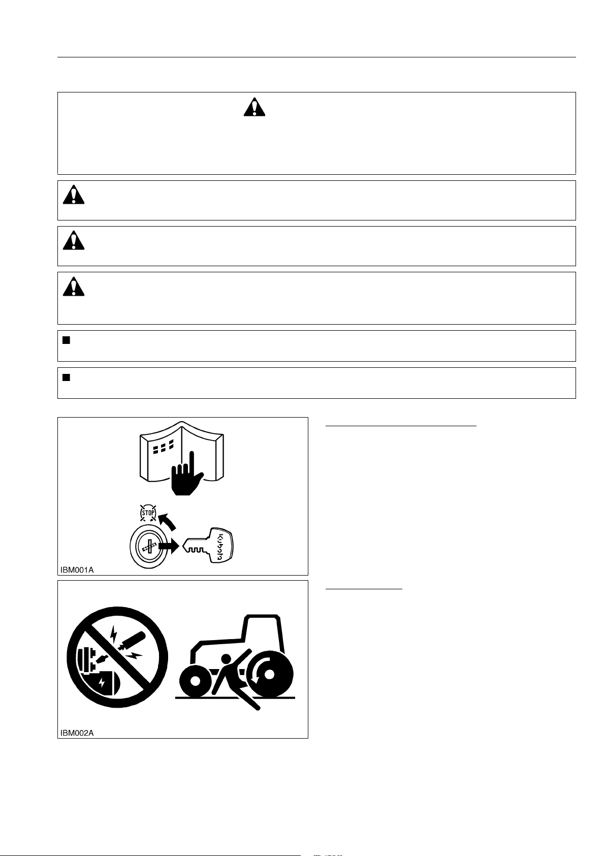
BEFORE YOU START SERVICE
• Read all instructions and safety instructions in this
manual and on your machine safety decals.
• Clean the work area and machine.
• Park the machine on a stable and level ground, and
set the parking brake.
• Lower the implement to the ground.
• Stop the engine, then remove the key.
• Disconnect the battery negative cable.
• Hang a "DO NOT OPERATE" tag in the operator
station.
WSM000001INI0010US0
START SAFELY
• Do not do the procedures below when you start the
engine.
– short across starter terminals
– bypass the safety start switch
• Do not alter or remove any part of machine safety
system.
• Before you start the engine, make sure that all shift
levers are in neutral positions or in disengaged
positions.
• Do not start the engine when you stay on the ground.
Start the engine only from operator's seat.
WSM000001INI0015US0
I-1
G23-2, G26-2, WSM
KiSC issued 02, 2014 A
INFORMATION
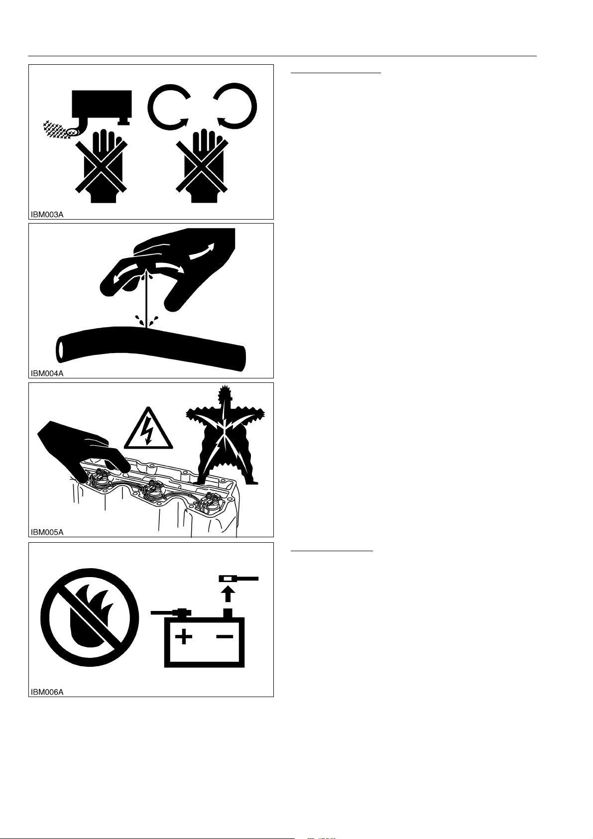
OPERATE SAFELY
• Do not use the machine after you consume alcohol
or medication or when you are tired.
• Put on applicable clothing and safety equipment.
• Use applicable tools only. Do not use alternative
tools or parts.
• When 2 or more persons do servicing, make sure
that you do it safely.
• Do not operate below the machine that only a jack
holds. Always use a safety stand to hold the
machine.
• Do not touch the hot parts or parts that turn when the
engine operates.
• Do not remove the radiator cap when the engine
operates, or immediately after it stops. If not, hot
water can spout out from the radiator. Only remove
the radiator cap when it is at a sufficiently low
temperature to touch with bare hands. Slowly loosen
the cap to release the pressure before you remove it
fully.
• Released fluid (fuel or hydraulic oil) under pressure
can cause damage to the skin and cause serious
injury. Release the pressure before you disconnect
hydraulic or fuel lines. Tighten all connections before
you apply the pressure.
• Do not open a fuel system under high pressure.
The fluid under high pressure that stays in fuel lines
can cause serious injury. Do not disconnect or repair
the fuel lines, sensors, or any other components
between the fuel pump and injectors on engines with
a common rail fuel system under high pressure.
• Put on an applicable ear protective device (earmuffs
or earplugs) to prevent injury against loud noises.
• Be careful about electric shock. The engine
generates a high voltage of more than DC100 V in
the ECU and is applied to the injector.
WSM000001INI0012US0
PREVENT A FIRE
• Fuel is very flammable and explosive under some
conditions. Do not smoke or let flames or sparks in
your work area.
• To prevent sparks from an accidental short circuit,
always disconnect the battery negative cable first
and connect it last.
• The battery gas can cause an explosion. Keep the
sparks and open flame away from the top of battery,
especially when you charge the battery.
• Make sure that you do not spill fuel on the engine.
WSM000001INI0005US0
I-2
G23-2, G26-2, WSM
KiSC issued 02, 2014 A
INFORMATION
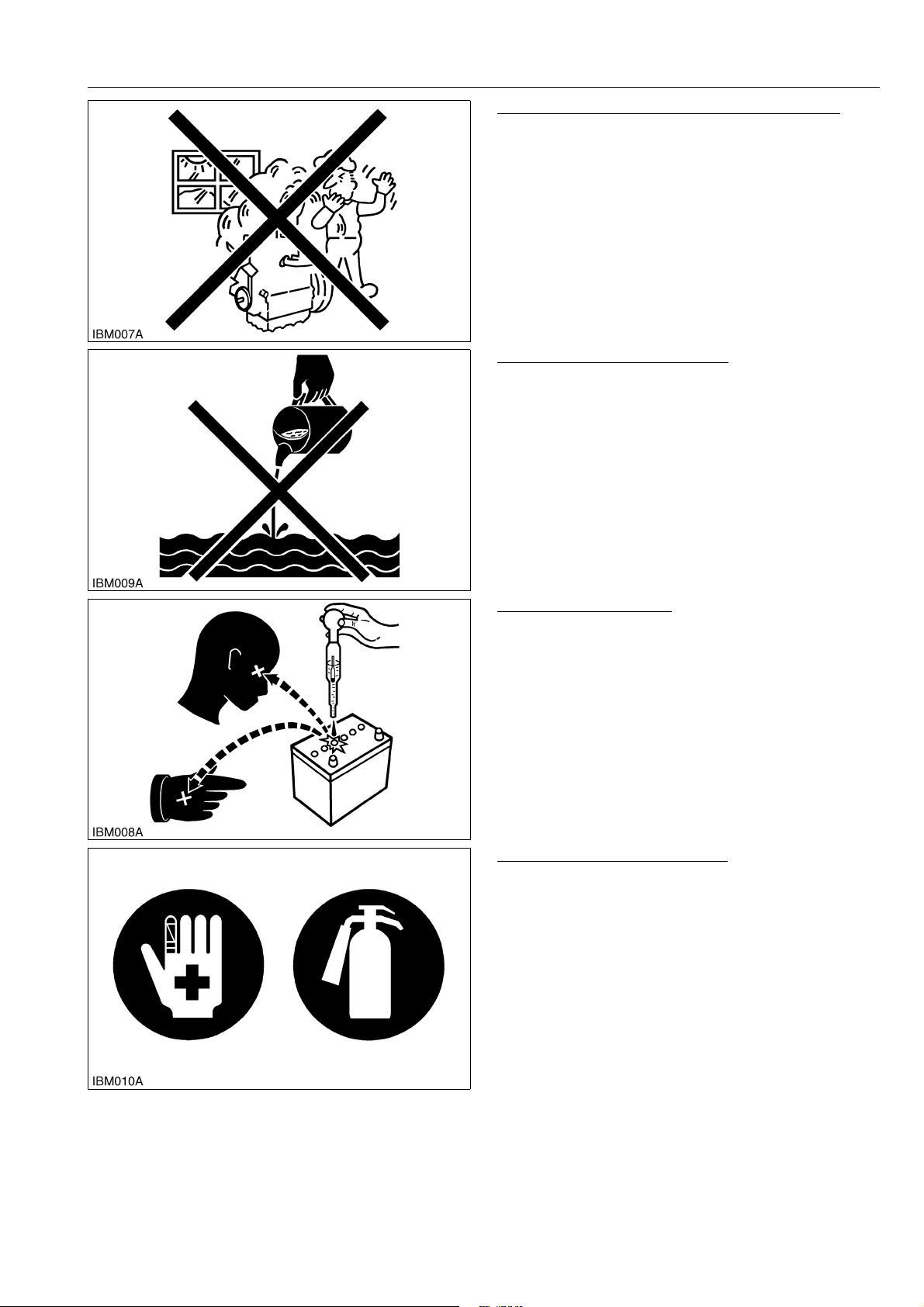
KEEP A GOOD AIRFLOW IN THE WORK AREA
• If the engine is in operation, make sure that the area
has good airflow. Do not operate the engine in a
closed area. The exhaust gas contains poisonous
carbon monoxide.
WSM000001INI0006US0
DISCARD FLUIDS CORRECTLY
• Do not discard fluids on the ground, down the drain,
into a stream, pond, or lake. Obey related
environmental protection regulations when you
discard oil, fuel, coolant, electrolyte and other
dangerous waste.
WSM000001INI0007US0
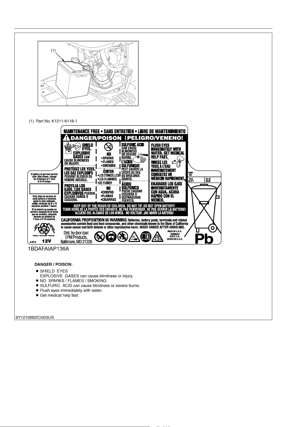
PREVENT ACID BURNS
• Keep electrolyte away from your eyes, hands and
clothing. Sulfuric acid in battery electrolyte is
poisonous and it can burn your skin and clothing and
cause blindness. If you spill electrolyte on yourself,
clean yourself with water, and get medical aid
immediately.
WSM000001INI0008US0
PREPARE FOR EMERGENCIES
• Keep a first aid kit and fire extinguisher ready at all
times.
• Keep the emergency contact telephone numbers
near your telephone at all times.
WSM000001INI0009US0
I-3
G23-2, G26-2, WSM
KiSC issued 02, 2014 A
INFORMATION
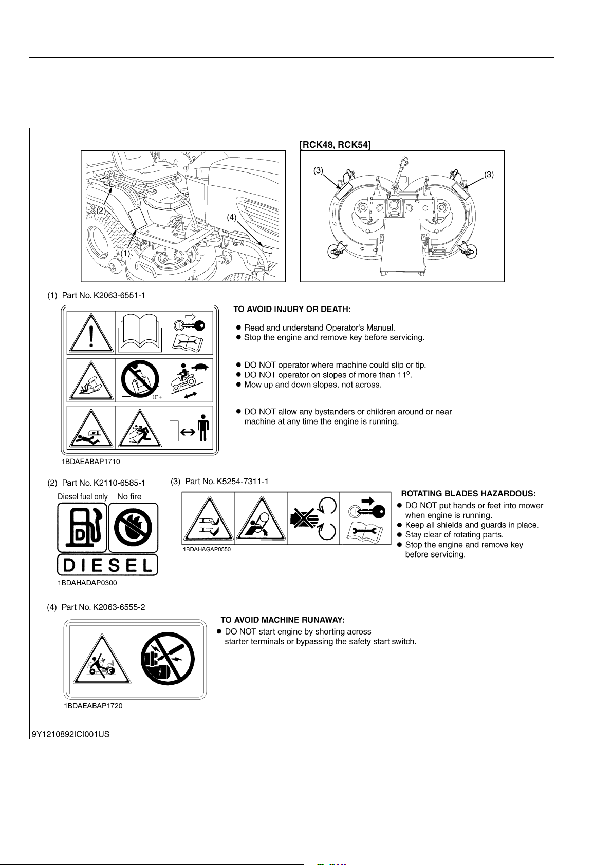
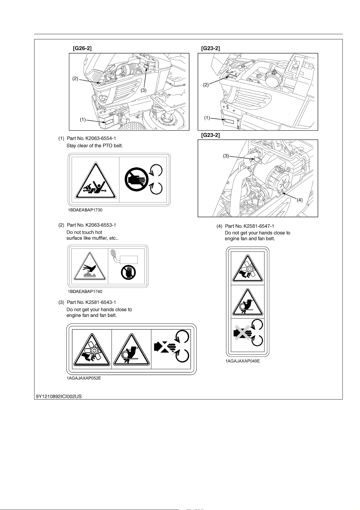
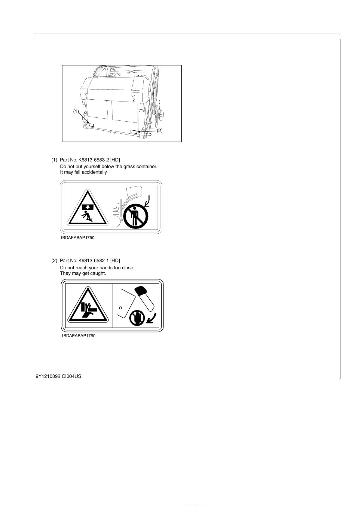
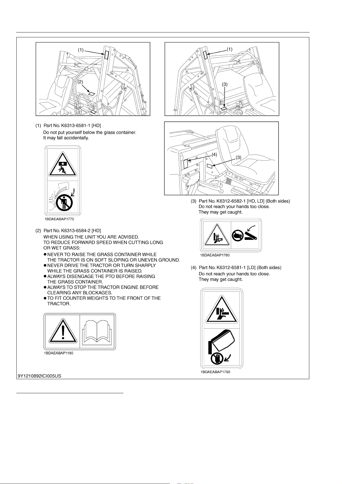
2. SAFETY DECALS
The following safety decals (pictorial safety labels) are installed on the machine. If a decal becomes
damaged, illegible or is not on the machine, replace it. The decal part number is listed in the parts list.
WSM000001INI0014US0
9Y1210892INI0001US0
I-4
G23-2, G26-2, WSM
KiSC issued 02, 2014 A
INFORMATION
9Y1210892INI0002US0
I-5
G23-2, G26-2, WSM
KiSC issued 02, 2014 A
INFORMATION
9Y1210892INI0003US0
I-6
G23-2, G26-2, WSM
KiSC issued 02, 2014 A
INFORMATION
9Y1210892INI0004US0
I-7
G23-2, G26-2, WSM
KiSC issued 02, 2014 A
INFORMATION
9Y1210892INI0005US0
CARE OF PICTORIAL SAFETY LABELS
1. Keep pictorial safety labels clean and free from obstructing material.
2. Clean pictorial safety labels with soap and water, dry with a soft cloth.
3. Replace damaged or missing pictorial safety labels with new labels.
4. If a component with pictorial safety label(s) affixed is replace with new part, make sure new label(s) is (are)
attached in the same location(s) as the replace component.
5. Mount new pictorial safety labels by applying on a clean dry surface and pressure any bubbles to outside edge.
9Y1210892INI0006US0
I-8

G23-2, G26-2, WSM
NOTE
KiSC issued 02, 2014 A
3. SPECIFICATIONS
INFORMATION
Engine
Capacities
Machine
Dimensions
Mower
Grass
collector
Model
Model D902-E3-GT D1005-E3-GT
Type Liquid-cooled diesel
Total displacement 898 cm
Gross power 17.1 kW (23.3 HP) 18.8 kW (25.5 HP)
Number of cylinders 3
Starter Electric starter with battery
Battery 12V, RC: 80 min, CCA: 535A
Fuel
Preheating system Super glow
Engine stop Key stop
Fuel tank 20 L (5.3 U.S.gals, 4.4 Imp.gals)
Engine oil 3.1 L (3.3 U.S.qts, 2.7 Imp.qts) 3.5 L (3.7 U.S.qts, 3.1 Imp.qts)
Radiator coolant 3.1 L (3.3 U.S.qts, 2.7 Imp.qts) 3.3 L (3.5 U.S.qts, 2.9 Imp.qts)
Hydrostatic transmission oil 11 L (12 U.S.qts, 9.7 Imp.qts)
PTO Shaft drive
PTO clutch Belt tension Wet disks
PTO brake Shoe Wet disks
Tyres
Steering type Hydrostatic type power steering
Brakes Wet Discs
Travel speed control Foot pedal
Transmission Hydrostatic
Traveling
speeds
Overall length
(with grass collector), without
front weight bracket for HD
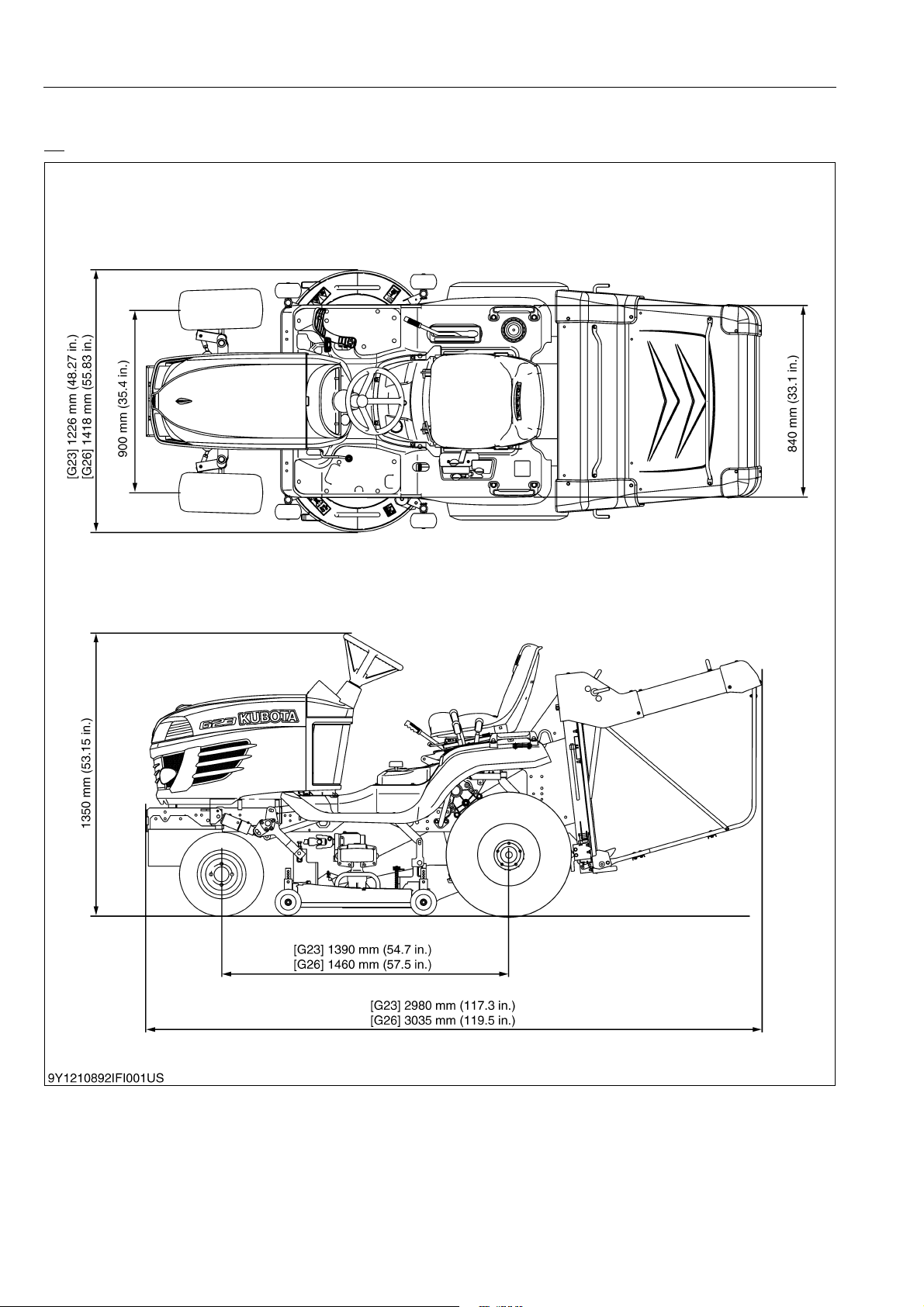
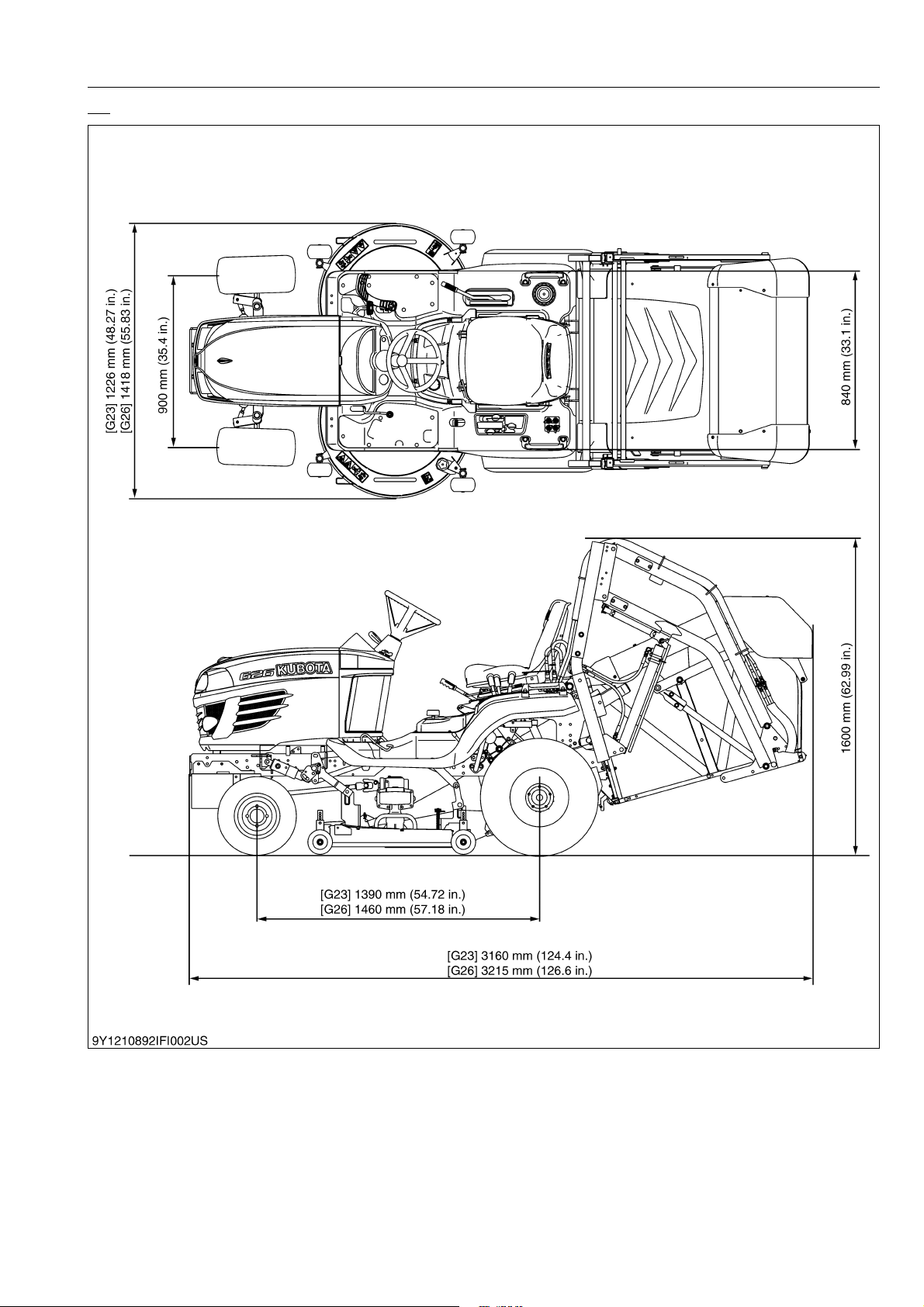
Overall width (with mower) 1226 mm (48.27 in.) 1418 mm (55.83 in.)
Overall height 1350 mm (53.15 in.) 1600 mm (62.99 in.) 1350 mm (53.15 in.) 1600 mm (62.99 in.)
Wheel base 1390 mm (54.72 in.) 1460 mm (57.18 in.)
Tyead
Weight (Without mower deck
and grass collector)
Model RCK48-G23-2 RCK54-G26-2
Cutting width 1219 mm (48.0 in.) 1372 mm (54.0 in.)
Cutting height 25 to 102 mm (1.0 to 4.0 in.)
Adjustment of cutting height Dial gauge
Mounting method Quick joint, parallel linkage
Weight (Approx.) 120 kg (265 lbs) 135 kg (298 lbs)
Dimensions
Discharge direction Rear
Gear box oil 1.9 L (2.0 U.S.qts, 1.7 Imp.qts) 2.1 L (2.2 U.S.qts, 1.8 Imp.qts)
Model GCK-G23LD GCK-G26HD
Container capacity 560 L (148 U.S.gals, 123 Imp.gals) 640 L (169 U.S.gals, 141 Imp.gals)
Weight (Approx.) 35 kg (77 lbs) 220 kg (485 lbs)
Front 16 × 7.50-8
Rear 24 × 12.00-12
Forward 0 to 15.5 km/h (0 to 9.6 mph) 0 to 17.0 km/h (0 to 10.6 mph)
Reverse 0 to 10.0 km/h (0 to 6.2 mph)
2980 mm (117.3 in.) 3160 mm (124.4 in.) 3035 mm (119.5 in.) 3215 mm (126.6 in.)
Front 900 mm (35.4 in.)
Rear 840 mm (33.1 in.)
Total length 895 mm (35.2 in.) 980 mm (38.6 in.)
Total width 1266 mm (49.8 in.) 1418 mm (55.8 in.)
Total height 400 mm (15.8 in.)
LD HD LD HD
535 kg (1180 lbs) 500 kg (1100 lbs) 565 kg (1250 lbs) 535 kg (1180 lbs)
G23-2 G26-2
3
(54.8 cu.in.) 1001 cm3 (61.1 cu.in.)
Diesel fuel No. 1 [below – 10 °C (14 °F)]
Diesel fuel No. 2 [above – 10 °C (14 °F)]
• The company reserves the right to change the specifications without notice.
9Y1210892INI0007US0
I-9
G23-2, G26-2, WSM
KiSC issued 02, 2014 A
4. DIMENSIONS
LD
INFORMATION
9Y1210892INI0008US0
I-10
G23-2, G26-2, WSM
KiSC issued 02, 2014 A
HD
INFORMATION
9Y1210892INI0009US0
I-11

G GENERAL
KiSC issued 02, 2014 A

GENERAL
KiSC issued 02, 2014 A
CONTENTS
1. MACHINE IDENTIFICATION........................................................................................................G-1
[1] SERIAL NUMBER .................................................................................................................. G-1
[2] CYLINDER NUMBER ............................................................................................................. G-2
2. GENERAL PRECAUTIONS.......................................................................................................... G-3
3. HANDLING PRECAUTIONS FOR ELECTRICAL PARTS AND WIRING .................................... G-4
[1] WIRING .................................................................................................................................. G-4
[2] BATTERY ............................................................................................................................... G-6
[3] FUSE ...................................................................................................................................... G-6
[4] CONNECTOR ........................................................................................................................ G-6
[5] HANDLING OF CIRCUIT TESTER ........................................................................................ G-7
[6] COLOR OF WIRING ..............................................................................................................G-8
4. LUBRICANTS, FUEL AND COOLANT......................................................................................... G-9
5. TIGHTENING TORQUES ........................................................................................................... G-12
[1] GENERAL USE SCREWS, BOLTS AND NUTS .................................................................. G-12
[2] STUD BOLTS ....................................................................................................................... G-12
[3] AMERICAN STANDARD SCREWS, BOLTS AND NUTS WITH UNC OR UNF
THREADS ............................................................................................................................ G-13
[4] PLUGS ................................................................................................................................. G-13
6. MAINTENANCE CHECK LIST ................................................................................................... G-14
7. CHECK AND MAINTENANCE ................................................................................................... G-16
[1] DAILY CHECK...................................................................................................................... G-16
(1) Walking Around the Machine.......................................................................................... G-16
(2) Mower............................................................................................................................. G-19
(3) While Sitting on the Operator's Seat .............................................................................. G-19
(4) Turning the Key Switch "ON".......................................................................................... G-19
(5) Starting the Engine ......................................................................................................... G-19
(6) Others............................................................................................................................. G-20
[2] CHECK POINTS OF INITIAL 50 HOURS ............................................................................ G-20
[3] CHECK POINTS OF EVERY 50 HOURS ............................................................................ G-22
[4] CHECK POINTS OF EVERY 100 HOURS .......................................................................... G-37
[5] CHECK POINT OF EVERY 150 HOURS ............................................................................. G-39
[6] CHECK POINTS OF EVERY 200 HOURS .......................................................................... G-40
[7] CHECK POINTS OF EVERY 400 HOURS .......................................................................... G-45
[8] CHECK POINT OF EVERY 1500 HOURS ........................................................................... G-46
[9] CHECK POINT OF EVERY 3000 HOURS ........................................................................... G-46
[10]CHECK POINT OF EVERY 1 YEAR .................................................................................... G-46
[11]CHECK POINTS OF EVERY 2 YEARS ............................................................................... G-47
.......
[12]OTHERS.......................................................................................................................
8. SPECIAL TOOLS ....................................................................................................................... G-55
[1] SPECIAL TOOLS FOR ENGINE .......................................................................................... G-55
[2] SPECIAL TOOLS FOR MACHINE ....................................................................................... G-60
9. TYRE PRESSURE AND WHEEL ............................................................................................... G-62
[1] TYRE PRESSURE ............................................................................................................... G-62
[2] WHEEL................................................................................................................................. G-62
10. IMPLEMENT LIMITATIONS ....................................................................................................... G-63
. G-51
G23-2, G26-2, WSM
KiSC issued 02, 2014 A
1. MACHINE IDENTIFICATION
[1] SERIAL NUMBER
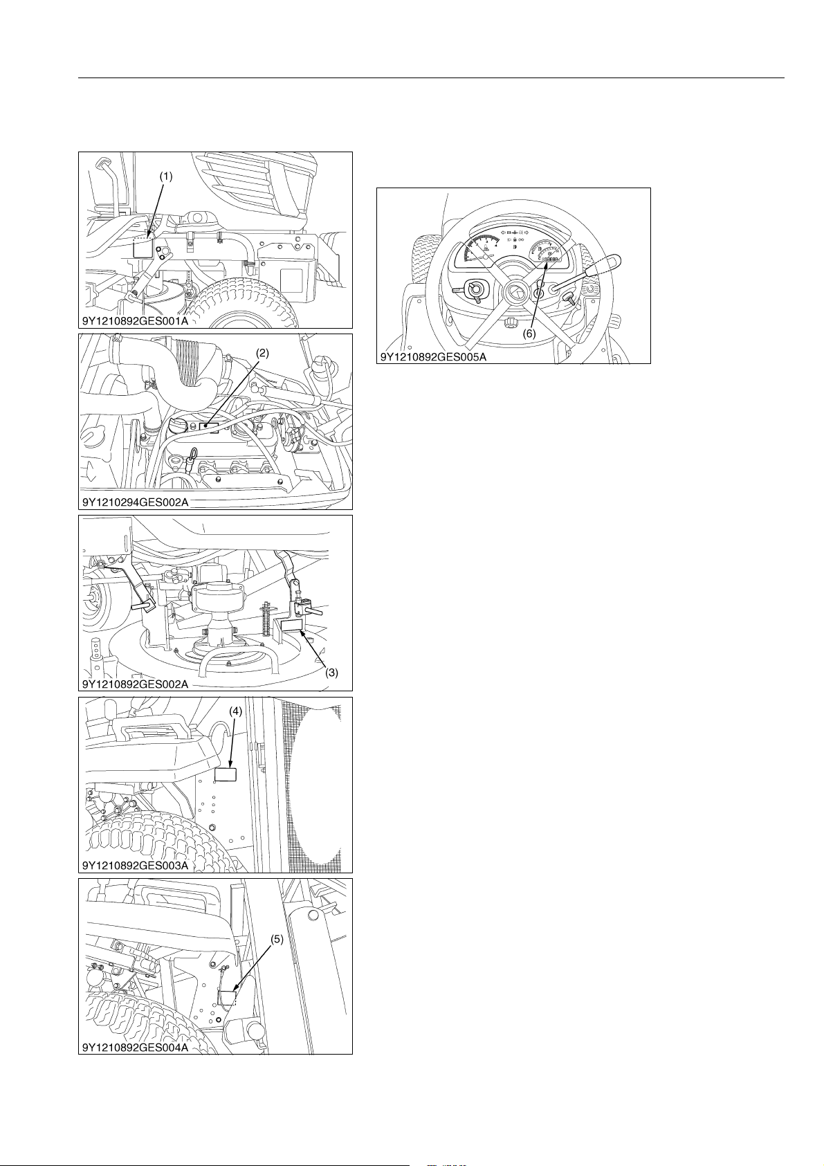
When contacting your local KUBOTA distributor, always specify
engine serial number, tractor serial number and hour meter reading.
GENERAL
(1) Machine Serial Number
(2) Engine Serial Number
(3) Mower Serial Number
(4) Grass Catcher Serial Number (LD)
(5) Grass Catcher Serial Number (HD)
(6) Hour Meter / Tachometer
9Y1210892GEG0001US0
G-1

G23-2, G26-2, WSM
KiSC issued 02, 2014 A
[2] CYLINDER NUMBER
GENERAL
You can see the cylinder numbers of KUBOTA diesel engine in
the figure. The sequence of cylinder numbers is No. 1, No. 2 and
No. 3 and it starts from the gear case side.
WSM000001GEG0056US0
G-2
G23-2, G26-2, WSM
KiSC issued 02, 2014 A
2. GENERAL PRECAUTIONS
• When you disassemble, carefully put the parts in a clean area
to make it easy to find the parts. You must install the screws,
bolts and nuts in their initial position to prevent the reassembly
errors.
• When it is necessary to use special tools, use KUBOTA special
tools. Refer to the drawings when you make special tools that
you do not use frequently.
• Before you disassemble or repair machine, make sure that you
always disconnect the ground cable from the battery first.
• Remove oil and dirt from parts before you measure.
• Use only KUBOTA genuine parts for replacement to keep the
machine performance and to make sure of safety.
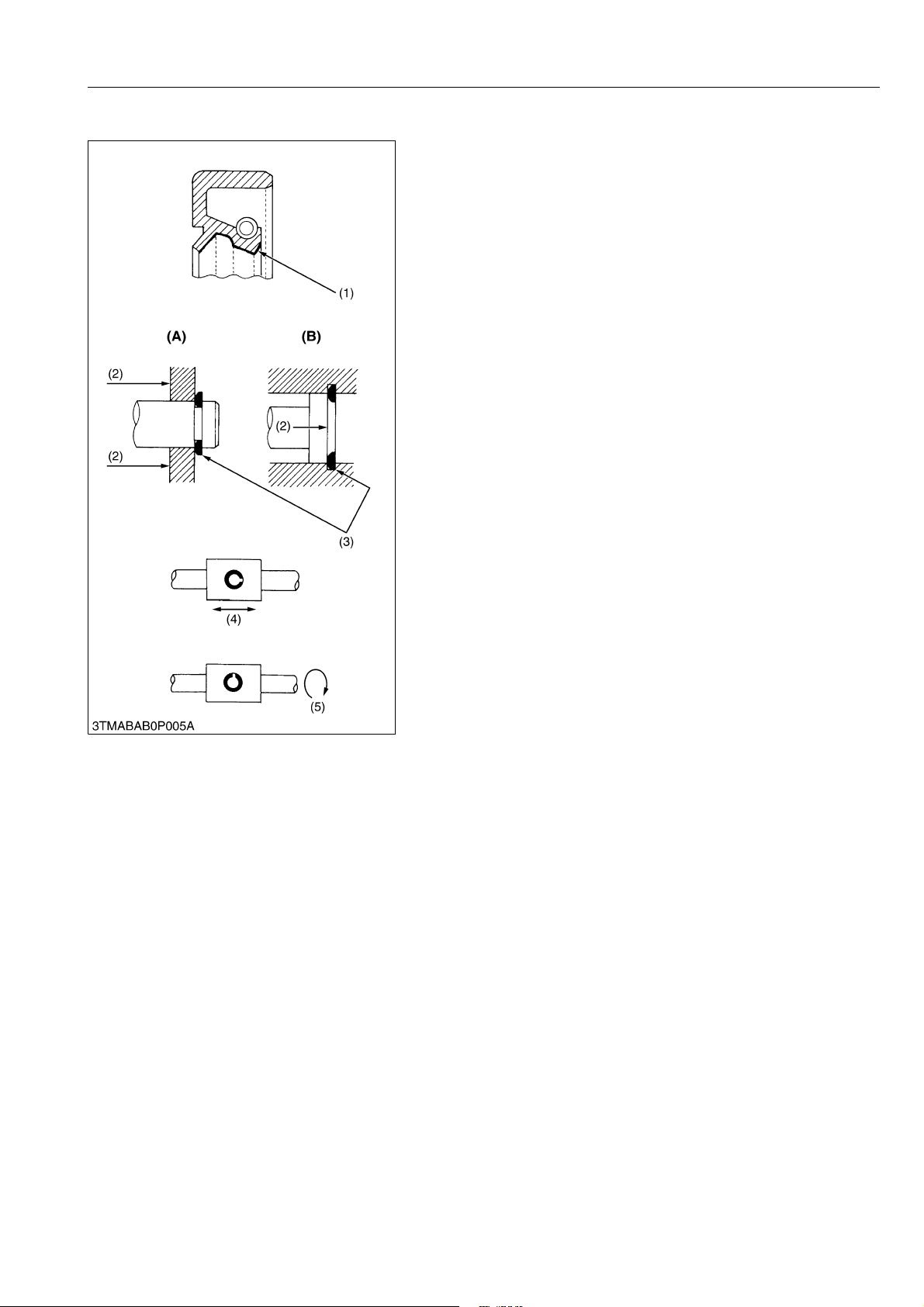
• You must replace the gaskets and O-rings when you assemble
again. Apply grease (1) to new O-rings or oil seals before you
assemble.
• When you assemble the external or internal circlips, make sure
that the sharp edge (3) faces against the direction from which
force (2) is applied.
• When inserting spring pins, their splits must face the direction
from which a force is applied. See the figure on the left side.
• To prevent damage to the hydraulic system, use only specified
fluid or equivalent.
(1) Grease
(2) Force
(3) Sharp Edge
(4) Axial Force
(5) Rotating Movement
GENERAL
(A) External Circlip
(B) Internal Circlip
WSM000001GEG0092US0
G-3
G23-2, G26-2, WSM
IMPORTANT
KiSC issued 02, 2014 A
GENERAL
3. HANDLING PRECAUTIONS FOR ELECTRICAL PARTS AND WIRING
To ensure safety and prevent damage to the machine and
surrounding equipment, obey the following precautions in handling
electrical parts and wiring.
• Check electrical wiring for damage and loosened
connection every year. To this end, educate the customer
to do his or her own check and at the same time
recommend the dealer to perform periodic check for a fee.
• Do not try to modify or remodel any electrical parts and
wiring.
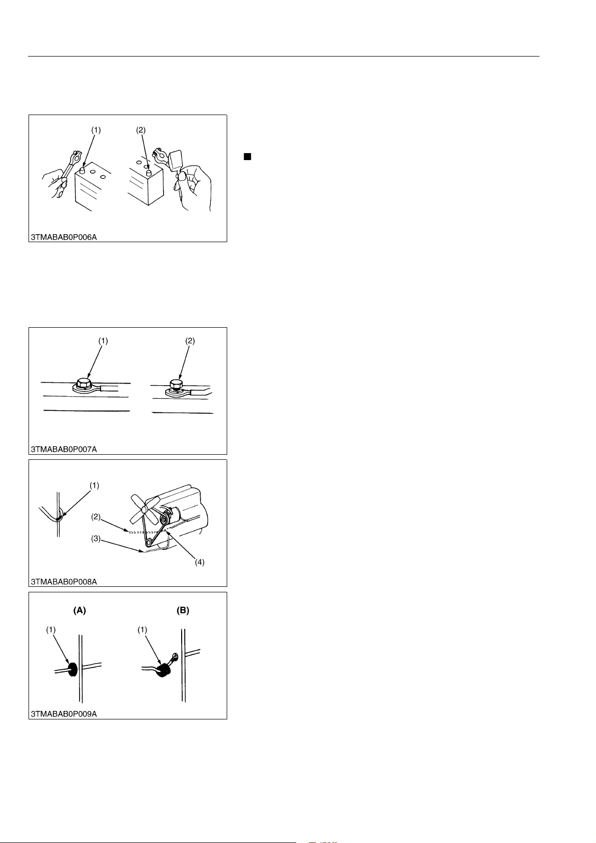
• When removing the battery cables, disconnect the negative
cable first. When installing the battery cables, connect the
positive cable first.
(1) Negative Terminal (2) Positive Terminal
WSM000001GEG0062US0
[1] WIRING
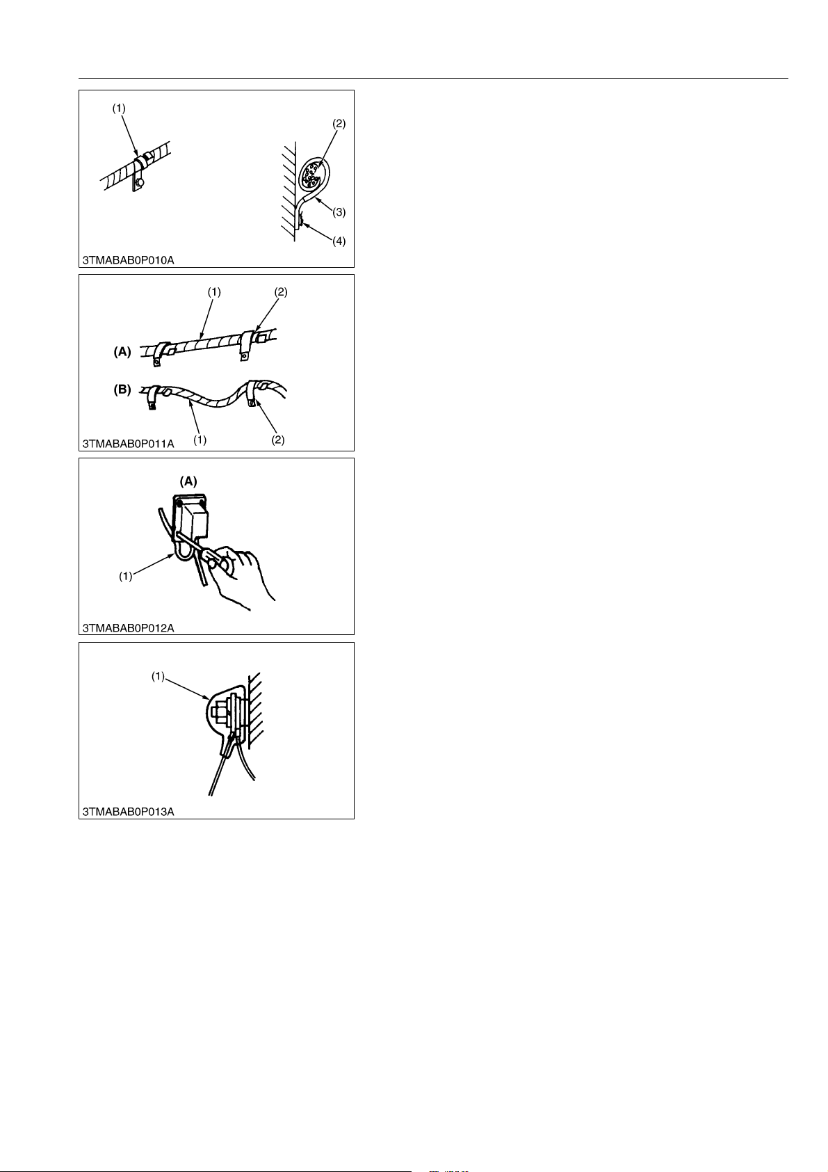
• Securely tighten wiring terminals.
(1) Correct
(Securely Tighten)
(2) Incorrect
(Loosening Leads to Faulty Contact)
WSM000001GEG0063US0
• Do not let wiring contact dangerous part.
(1) Dangerous Part (Sharp Edge)
(2) Wiring (Incorrect)
(3) Wiring (Correct)
(4) Dangerous Part
• Securely insert grommet.
(1) Grommet (A) Correct
(B) Incorrect
WSM000001GEG0064US0
WSM000001GEG0066US0
G-4
G23-2, G26-2, WSM
KiSC issued 02, 2014 A
GENERAL
• Securely clamp, being careful not to damage wiring.
(1) Clamp
(Wind Clamp Spirally)
(2) Wire Harness
(3) Clamp
(4) Welding Dent
WSM000001GEG0067US0
• Clamp wiring so that there is no twist, unnecessary sag, or
excessive tension, except for movable part, where sag be
required.
(1) Wiring
(2) Clamp
(A) Correct
(B) Incorrect
WSM000001GEG0068US0
• In installing a part, be careful not to get wiring caught by it.
(1) Wiring (A) Incorrect
WSM000001GEG0069US0
• After installing wiring, check protection of terminals and
clamped condition of wiring.
(1) Cover
(Securely Install Cover)
WSM000001GEG0070US0
G-5
G23-2, G26-2, WSM
CAUTION
KiSC issued 02, 2014 A
[2] BATTERY
GENERAL
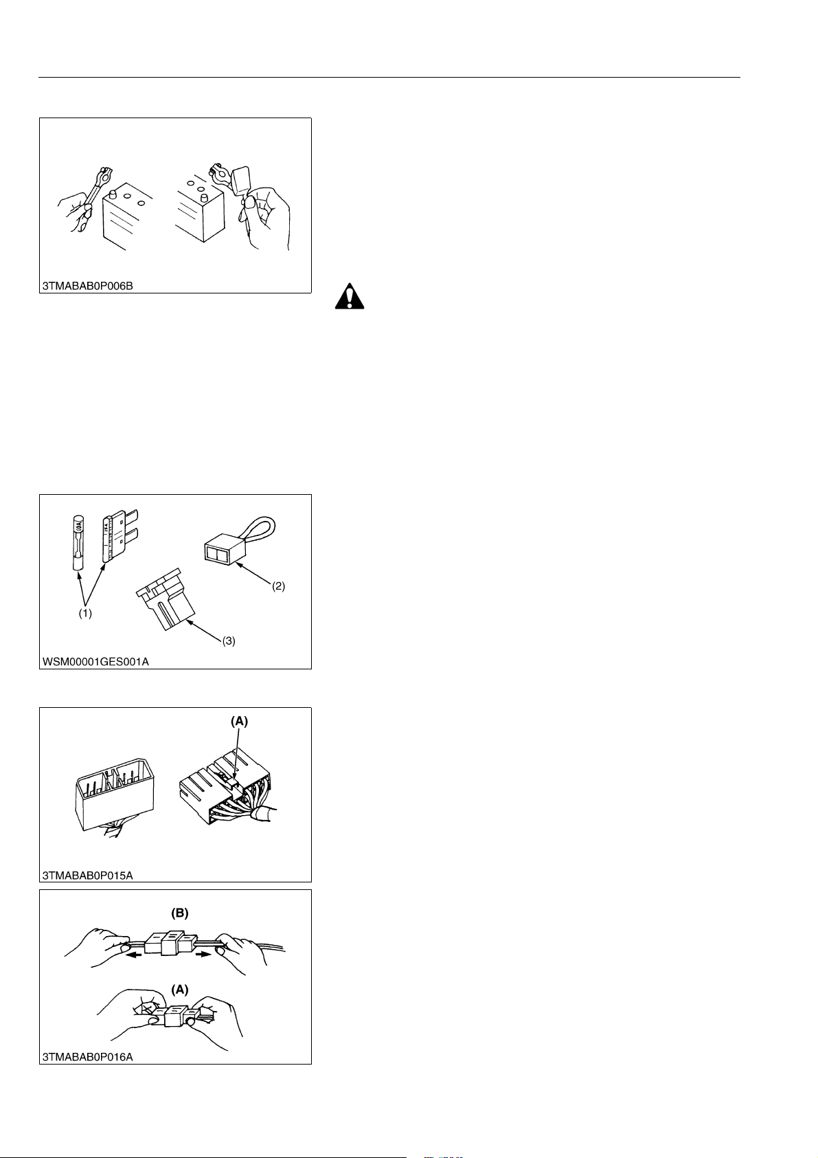
• Be careful not to confuse positive and negative terminal posts.
• When you remove battery cables, disconnect negative cable
first. When you install battery cables, check for polarity and
connect positive cable first.
• Do not install any battery with capacity other than is specified
(Ah).
• After you connect cables to battery terminal posts, apply high
temperature grease to them and securely install terminal covers
on them.
• Do not allow dirt and dust to collect on battery.
• Be careful not to let battery liquid spill on your skin and
clothes. If contaminated, wash it off with water
immediately.
• Before you recharge the battery, remove it from the
machine.
• Before you recharge, remove cell caps.
• Recharge in a well-ventilated place where there is no open
flame nearby, as hydrogen gas and oxygen are formed.
WSM000001GEG0071US0
[3] FUSE
[4] CONNECTOR
• Use fuses with specified capacity.
Neither too large nor small capacity fuse is acceptable.
• Never use steel nor copper wire in place of fuse.
• Do not install working light, radio set, etc. on machine which is
not provided with reserve power supply.
• Do not install accessories if fuse capacity of reserve power
supply is exceeded.
(1) Fuse
(2) Fusible Link
(3) Slow Blow Fuse
WSM000001GEG0072US0
• For connector with lock, push lock to separate.
(A) Push
WSM000001GEG0073US0
• In separating connectors, do not pull wire harnesses.
• Hold connector bodies to separate.
(A) Correct (B) Incorrect
WSM000001GEG0074US0
G-6
G23-2, G26-2, WSM
KiSC issued 02, 2014 A
GENERAL
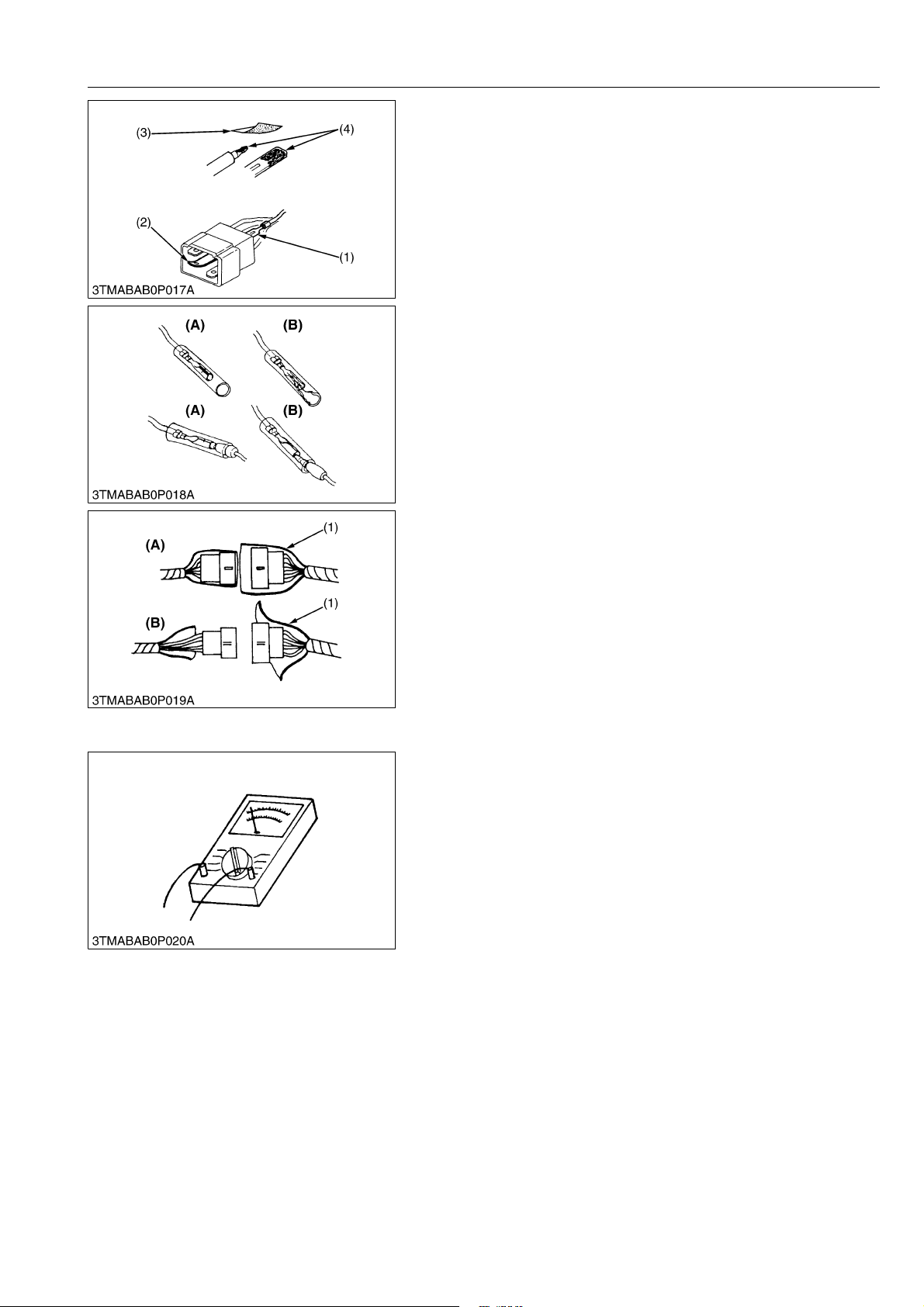
• Use sandpaper to remove rust from terminals.
• Repair deformed terminal. Make sure that there is no terminal
being exposed or displaced.
(1) Exposed Terminal
(2) Deformed Terminal
(3) Sandpaper
(4) Rust
WSM000001GEG0075US0
• Make sure that there is no female connector being too open.
(A) Correct (B) Incorrect
WSM000001GEG0076US0
• Make sure that plastic cover is large enough to cover whole
connector.
(1) Cover (A) Correct
(B) Incorrect
WSM000001GEG0077US0
[5] HANDLING OF CIRCUIT TESTER
• Use tester correctly following manual provided with tester.
• Check for polarity and range.
WSM000001GEG0078US0
G-7

G23-2, G26-2, WSM
KiSC issued 02, 2014 A
[6] COLOR OF WIRING
GENERAL
• Colors of wire are specified to the color codes.
• This symbol of "/" shows color with stripe(s).
(An example)
Red stripe on white color: W/R
Color of wiring Color code
Black B
Brown Br
Green G
Gray Gy or Gr
Blue L
Light Green Lg
Orange Or
Pink P
Purple Pu or V
Red R
Sky Blue Sb
White W
Yellow Y
(1) Wire Color (2) Stripe
WSM000001GEG0079US0
G-8

G23-2, G26-2, WSM
KiSC issued 02, 2014 A
4. LUBRICANTS, FUEL AND COOLANT
Capacities
No. Place
LD HD LD HD
1Fuel
Coolant
2
(with recovery tank)
3 Engine crankcase
4 Transmission case
5 Mower gear box
3.1 L
3.3 U.S.qts
2.7 Imp.qts
3.1 L*
3.3 U.S.qts
2.7 Imp.qts
1.9 L
2.0 U.S.qts
1.7 Imp.qts
20 L
5.3 U.S.gals
4.4 Imp.gals
3.3 L
3.5 U.S.qts
2.9 Imp.qts
3.5 L*
3.7 U.S.qts
3.1 Imp.qts
11 L
12 U.S.qts
9.7 Imp.qts
2.1 L
2.2 U.S.qts
1.8 Imp.qts
• No. 2-D diesel fuel
• No. 1-D diesel fuel if temperature
is below –10 °C (14 °F)
Fresh clean water with anti-freeze
Engine oil
API Service Classification CD, CE
or CF
• Above 25 °C (77 °F)
SAE30W,
SAE10W-30 or 15W-40
• 0 to 25 °C (32 to 77 °F)
SAE20, SAE10W-30 or 15W-40
• Below 0 °C (32 °F)
SAE10W,
SAE10W-30 or 15W-40
KUBOTA UDT or SUPER UDT fluid*
KUBOTA UDT or SUPER UDT fluid*
GENERAL
LubricantsG23-2 G26-2
G-9
G23-2, G26-2, WSM
NOTE
IMPORTANT
KiSC issued 02, 2014 A
No. Place
Front axle (King pin) 2
Front axle (Centre pin) 1
Mower link 10
Brake pedal link 6
HST speed change pedal
dumper
HST pedal boss 1
Tension PTO arm 1
PTO (Spline) 1
Parking lock pedal link 2
Cruise control link 2
Differential lock pedal link 4
Under duct pivot 4
Sensor system pivot 2
Duct cleanup system link 4
Seat adjuster 2
Seat pivot 2
6
Throttle cable 1 Moderate amount Oil
Mower universal joint 3
Mower universal joint
(Grease fitting)
Mower lift cylinder 5
Mower lift arm front (RH) 1
Mower lift link front 3
Mower lift arm rear (LH, RH) 4
Mower lift pin front (LH, RH) 2
Mower lift link rear (LH, RH) 4
Dump cylinder 2–2–
Grass container rotation pivot4–4–
Lock lever (LH, RH) 2–2–
Grass container pivot
(Grease fitting) (LH, RH)
Grass container lift cylinder
(LH, RH)
Dump pivot (LH, RH) –2–2
Greasing
No. of greasing point
LD HD LD HD
2
2
–10–10
–4–4
Capacity Type of greaseG23-2 G26-2
Until grease overflows
Until grease overflows
GENERAL
Multipurpose EP2
grease
(NLGI Grade No.2)
Multipurpose EP2
grease
(NLGI Grade No.2)
• * Oil amount when the oil level is at the upper level of the oil lever gauge.
• Check the oil lever of the transmission case with the mower lifted up and grass catcher lowered.
• To prevent serious damage to hydraulic system, use only KUBOTA genuine fluid or its equivalent.
9Y1210892GEG0002US0
G-10

G23-2, G26-2, WSM
NOTE
KiSC issued 02, 2014 A
GENERAL
Engine Oil
• Oil used in the engine should have an American Petroleum Institute (API) service classification and
Proper SAE Engine Oil according to the ambient temperatures as shown above :
• With the emission control now in effect, the CF-4 and CG-4 lubricating oils have been developed for use
of a low-sulfur fuel on on-road vehicle engines. When an off-road vehicle engine runs on a high-sulfur
fuel, it is advisable to employ the "CF or better" lubricating oil with a high Total Base Number (TBN of 10
minimum).
• Refer to the following table for the suitable API classification engine oil according to the engine type (with
internal EGR, external EGR or non-EGR) and the fuel (low-sulfur or high-sulfur fuel).
Fuel used
Engine oil classification (API classification)
Oil class of engines except external EGR Oil class of engines with external EGR
CF
High Sulfur Fuel
[≥ 0.05 % (500 ppm)]
(If the "CF-4, CG-4, CH-4, or CI-4"
lubricating oil is used with a high-sulfur
fuel, change the lubricating oil at shorter
—
intervals. (approximately half))
Low Sulfur Fuel
[< 0.05 % (500 ppm)] or
Ultra Low Sulfur Fuel
[< 0.0015 % (15 ppm)]
CF, CF-4, CG-4, CH-4 or CI-4
CF, CI-4
(Class CF-4, CG-4 and CH-4 engine oils
cannot be used on EGR type engines)
EGR: Exhaust Gas Re-circulation
• The CJ-4 engine oil is intended for DPF (Diesel Particulate Filter) Type engines, and cannot be used on
this machine.
except external EGR with external EGR
Models G23-2, G26-2 –
Fuel
• Cetane number of 45 minimum. Cetane number greater then 50 is preferred, especially for temperatures
below −20 °C (−4 °F) or elevations above 1500 m (5000 ft).
• If diesel fuel with sulfur content greater than 0.5 % (5000 ppm) sulfur content in used, reduce the service
interval for engine oil and filter by 50%.
• NEVER use diesel fuel with sulfur content greater than 0.05% (500 ppm) for EXTERNAL EGR type engine.
• DO NOT use diesel fuel with sulfur content greater than 1.0% (10000 ppm).
• Diesel fuels specified to EN 590 or ASTM D975 are recommended.
• No.2-D is a distillate fuel of lower volatility for engine in industrial and heavy mobile service. (SAE J313
JUN87)
Transmission oil
• The oil used to lubricate the transmission is also used as hydraulic fluid. To insure proper operation of
the hydraulic system and to complete lubrication of the transmission, it is important that a multi-grade
transmission fluid is used in this system. We recommend the use of KUBOTA UDT or SUPER UDT fluid
for optimum protection and performance.
Do not mix different brands together.
Indicated capacities of water and oil are manufacturer's estimate.
9Y1210892GEG0003US0
G-11

G23-2, G26-2, WSM
KiSC issued 02, 2014 A
GENERAL
5. TIGHTENING TORQUES
[1] GENERAL USE SCREWS, BOLTS AND NUTS
Tighten screws, bolts and nuts whose tightening torques are not specified in this Workshop Manual
according to the table below.
Indication on top of bolt
Indication on top of nut
Material of opponent part Ordinariness Aluminum Ordinariness Aluminum Ordinariness
Unit N·m kgf·m lbf·ft N·m kgf·m lbf·ft N·m kgf·m lbf·ft N·m kgf·m lbf·ft N·m kgf·m lbf·ft
7.9
0.80
M6
M8
M10
M12
M14
M16
M18
M20
to
9.3
18
to
20
40
to
45
63
to
72
108
to
125
16
to
191
246
to
284
334
to
392
to
0.95
1.8
to
2.1
4.0
to
4.6
6.4
to
7.4
11. 0
to
12.8
7
17.0
to
19.5
25.0
to
29.0
34.0
to
40.0
No-grade or 4T 7T 9T
No-grade or 4T
5.8
7.9
0.80
5.8
9.81
1.00
7.24
7.9
0.80
5.8
to
to
to
1.7
to
2.0
3.2
to
3.5
to
6.5
13
to
14
24
to
25
6.8
8.8
0.90
13
17
to
to
15
19
32
29
to
to
33
34
47
to 53–––
79.6
to
92.5
–––
123
to
–––
141
181
to
–––
209
246
to
–––
289
to
11. 2
24
to
27
48
to
55
78
to
90
124
to
147
197
to
225
275
to
318
368
to
431
to
1.15
2.4
to
2.8
4.
9
to
5.7
7.9
to
9.2
12.6
to
15.0
20.0
to
23.0
28.0
to
32.5
37.5
to
44.0
to
8.31
18
to
20
36
to
41
58
to
66
91.2
to
108
145
to
166
203
to
235
272
to
318
to
to
8.8
0.90
18
1.8
to
to
20
2.1
40
4.0
to
to
44
4.5
63
6.4
to
to
72
7.4
––
–––
–––
–––
12.3
to
to
6.5
14.2
13
30
to
to
15
34
29
61
to
to
32
70
47
103
to
to
53
117
167
–
to
196
260
to
304
344
to
402
491
to
568
WSM000001GEG0001US0
6T
1.25
to
1.45
3.0
to
3.5
6.2
to
7.2
10.5
to
12.0
17.0
to
20.0
26.5
to
31.0
35.0
to
41.0
50.0
to
58.0
9.05
to
10.4
22
to
25
45
to
52
76.0
to
86.7
123
to
144
192
to
224
254
to
296
362
to
419
[2] STUD BOLTS
Material of opponent part Ordinariness Aluminum
Unit N·m kgf·m lbf·ft N·m kgf·m lbf·ft
12
1.2
8.7
M8
M10
M12
M14
M16
M18
to
15
25
to
31
30
to
49
62
to
73
98.1
to
112
172
to
201
to
1.6
2.5
to
3.2
3.0
to
5.0
6.3
to
7.5
10.0
to
11. 5
17.5
to
20.5
8.9
to
to
11
11
18
20
to
to
23
25
22
to 3631 3.2 23
46
to 54–––
72.4
to
83.1
–––
127
to
–––
148
0.90
to
1.2
2.0
to
2.6
6.5
to
8.6
15
to
18
WSM000001GEG0002US0
G-12
 Loading...