

Page 1

WORKSHOP MANUAL
KiSC issued 02, 2014 A
G23-2,G26-2
Page 2

TO THE READER
KiSC issued 02, 2014 A
This Workshop Manual tells the servicing personnel about the mechanism, servicing and
maintenance of the G23-2 and G26-2. It contains 4 parts: "Information", "General", "Mechanism" and
"Servicing".
Information
This section contains information below.
• Safety First
• Safety Label
• Specification
• Dimension
General
This section contains information below.
• Engine Identification
• Model Identification
• General Precautions
• Maintenance Check List
• Check and Maintenance
• Special Tools
Mechanism
This section contains information on the structure and the function of the unit. Before you continue
with the subsequent sections, make sure that you read this section.
Refer to the latest version of Workshop Manual (Code No. 9Y021-01870) for the diesel engine
mechanism that this workshop manual does not include.
Servicing
This section contains information below.
• Troubleshooting
• Servicing Specifications
• Tightening Torques
• Checking, Disassembling and Servicing
All illustrations, photographs and specifications contained in this manual are of the newest
information available at the time of publication.
KUBOTA reserves the right to change all information at any time without notice.
Since this manual includes many models, information or illustrations and photographs can show
more than one model.
January, 2013
© KUBOTA Corporation 2013
Page 3

Record of Revisions
KiSC issued 02, 2014 A
For pdf, use search function {Search word} to find all the revised locations.
Last digit
of the
Code No.
Issue
month
Main Revised Point and Corrective Measures {Search word}
1 2014.02 Correcting the errors. G-41,
Correcting of part names. 1-S23,
Reference
Page
2-S33
1-S30,
2-S26,
3-S7,
5-S10,
5-S17,
6-M2,
8-S4
Page 4

I INFORMATION
KiSC issued 02, 2014 A
Page 5

INFORMATION
KiSC issued 02, 2014 A
CONTENTS
1. SAFETY FIRST .............................................................................................................................. I-1
2. SAFETY DECALS .......................................................................................................................... I-4
3. SPECIFICATIONS.......................................................................................................................... I-9
4. DIMENSIONS ............................................................................................................................... I-10
Page 6
G23-2, G26-2, WSM
SAFETY FIRST
DANGER
WARNING
CAUTION
IMPORTANT
NOTE
KiSC issued 02, 2014 A
INFORMATION
1. SAFETY FIRST
• This symbol, the industry's "Safety Alert Symbol", is used throughout this manual and on labels on the
machine itself to warn of the possibility of personal injury. Read these instructions carefully.
• It is essential that you read the instructions and safety regulations before you try to repair or use this
unit.
• Indicates an imminently hazardous situation which, if not avoided, will result in death or serious injury.
• Indicates a potentially hazardous situation which, if not avoided, could result in death or serious injury.
• Indicates a potentially hazardous situation which, if not avoided, may result in minor or moderate
injury.
• Indicates that equipment or property damage could result if instructions are not followed.
• Gives helpful information.
WSM000001INI0001US1
BEFORE YOU START SERVICE
• Read all instructions and safety instructions in this
manual and on your machine safety decals.
• Clean the work area and machine.
• Park the machine on a stable and level ground, and
set the parking brake.
• Lower the implement to the ground.
• Stop the engine, then remove the key.
• Disconnect the battery negative cable.
• Hang a "DO NOT OPERATE" tag in the operator
station.
WSM000001INI0010US0
START SAFELY
• Do not do the procedures below when you start the
engine.
– short across starter terminals
– bypass the safety start switch
• Do not alter or remove any part of machine safety
system.
• Before you start the engine, make sure that all shift
levers are in neutral positions or in disengaged
positions.
• Do not start the engine when you stay on the ground.
Start the engine only from operator's seat.
WSM000001INI0015US0
I-1
Page 7
G23-2, G26-2, WSM
KiSC issued 02, 2014 A
INFORMATION
OPERATE SAFELY
• Do not use the machine after you consume alcohol
or medication or when you are tired.
• Put on applicable clothing and safety equipment.
• Use applicable tools only. Do not use alternative
tools or parts.
• When 2 or more persons do servicing, make sure
that you do it safely.
• Do not operate below the machine that only a jack
holds. Always use a safety stand to hold the
machine.
• Do not touch the hot parts or parts that turn when the
engine operates.
• Do not remove the radiator cap when the engine
operates, or immediately after it stops. If not, hot
water can spout out from the radiator. Only remove
the radiator cap when it is at a sufficiently low
temperature to touch with bare hands. Slowly loosen
the cap to release the pressure before you remove it
fully.
• Released fluid (fuel or hydraulic oil) under pressure
can cause damage to the skin and cause serious
injury. Release the pressure before you disconnect
hydraulic or fuel lines. Tighten all connections before
you apply the pressure.
• Do not open a fuel system under high pressure.
The fluid under high pressure that stays in fuel lines
can cause serious injury. Do not disconnect or repair
the fuel lines, sensors, or any other components
between the fuel pump and injectors on engines with
a common rail fuel system under high pressure.
• Put on an applicable ear protective device (earmuffs
or earplugs) to prevent injury against loud noises.
• Be careful about electric shock. The engine
generates a high voltage of more than DC100 V in
the ECU and is applied to the injector.
WSM000001INI0012US0
PREVENT A FIRE
• Fuel is very flammable and explosive under some
conditions. Do not smoke or let flames or sparks in
your work area.
• To prevent sparks from an accidental short circuit,
always disconnect the battery negative cable first
and connect it last.
• The battery gas can cause an explosion. Keep the
sparks and open flame away from the top of battery,
especially when you charge the battery.
• Make sure that you do not spill fuel on the engine.
WSM000001INI0005US0
I-2
Page 8
G23-2, G26-2, WSM
KiSC issued 02, 2014 A
INFORMATION
KEEP A GOOD AIRFLOW IN THE WORK AREA
• If the engine is in operation, make sure that the area
has good airflow. Do not operate the engine in a
closed area. The exhaust gas contains poisonous
carbon monoxide.
WSM000001INI0006US0
DISCARD FLUIDS CORRECTLY
• Do not discard fluids on the ground, down the drain,
into a stream, pond, or lake. Obey related
environmental protection regulations when you
discard oil, fuel, coolant, electrolyte and other
dangerous waste.
WSM000001INI0007US0
PREVENT ACID BURNS
• Keep electrolyte away from your eyes, hands and
clothing. Sulfuric acid in battery electrolyte is
poisonous and it can burn your skin and clothing and
cause blindness. If you spill electrolyte on yourself,
clean yourself with water, and get medical aid
immediately.
WSM000001INI0008US0
PREPARE FOR EMERGENCIES
• Keep a first aid kit and fire extinguisher ready at all
times.
• Keep the emergency contact telephone numbers
near your telephone at all times.
WSM000001INI0009US0
I-3
Page 9
G23-2, G26-2, WSM
KiSC issued 02, 2014 A
INFORMATION
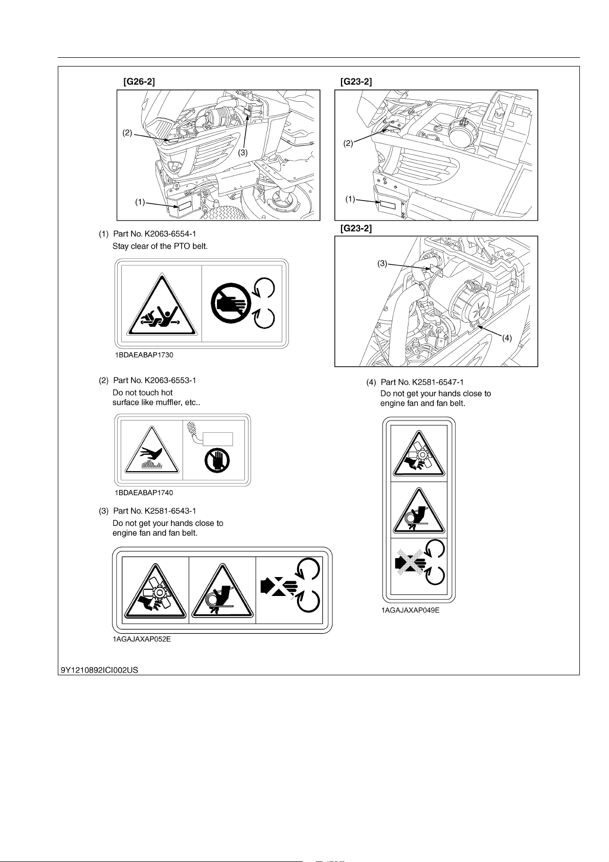
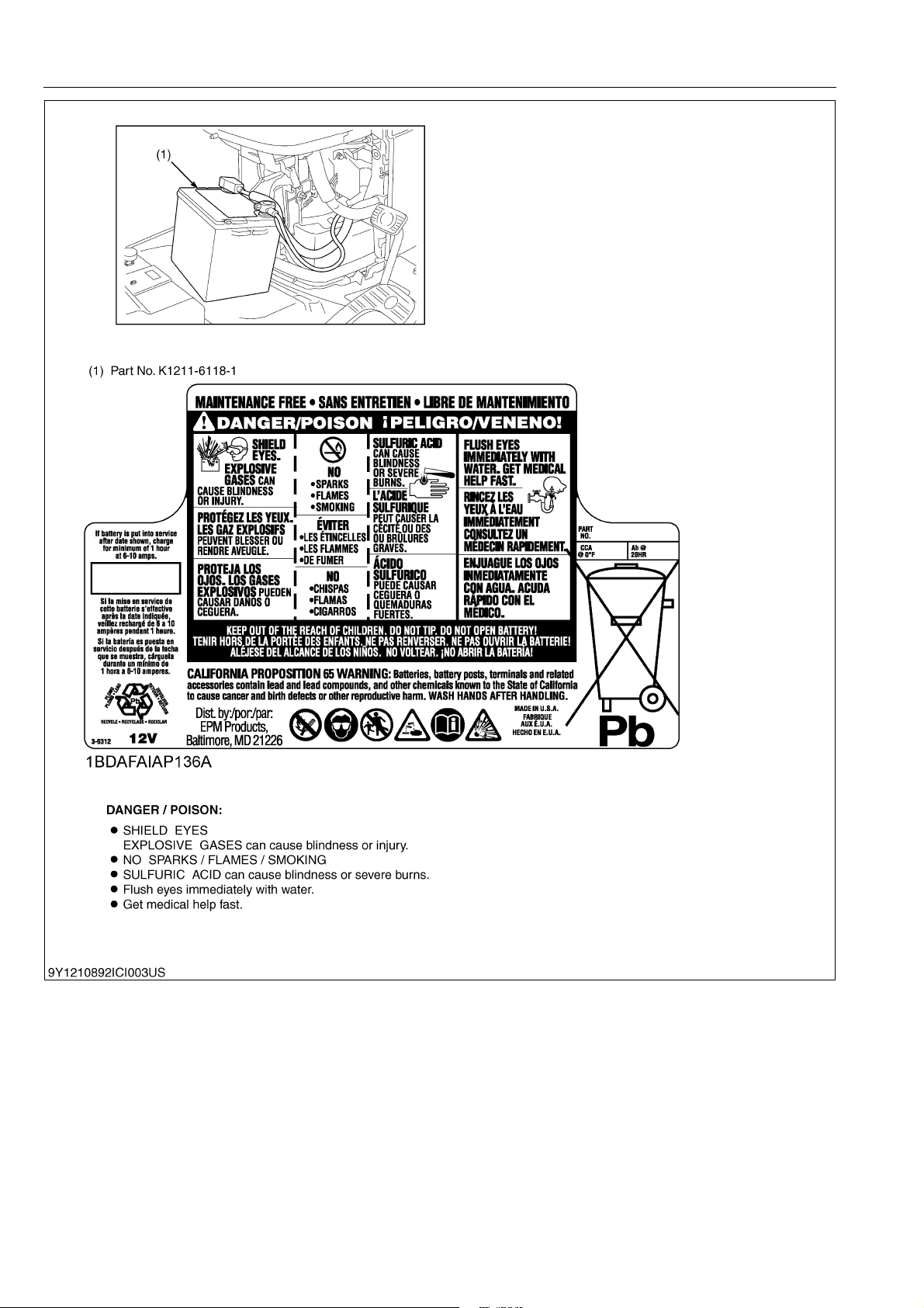
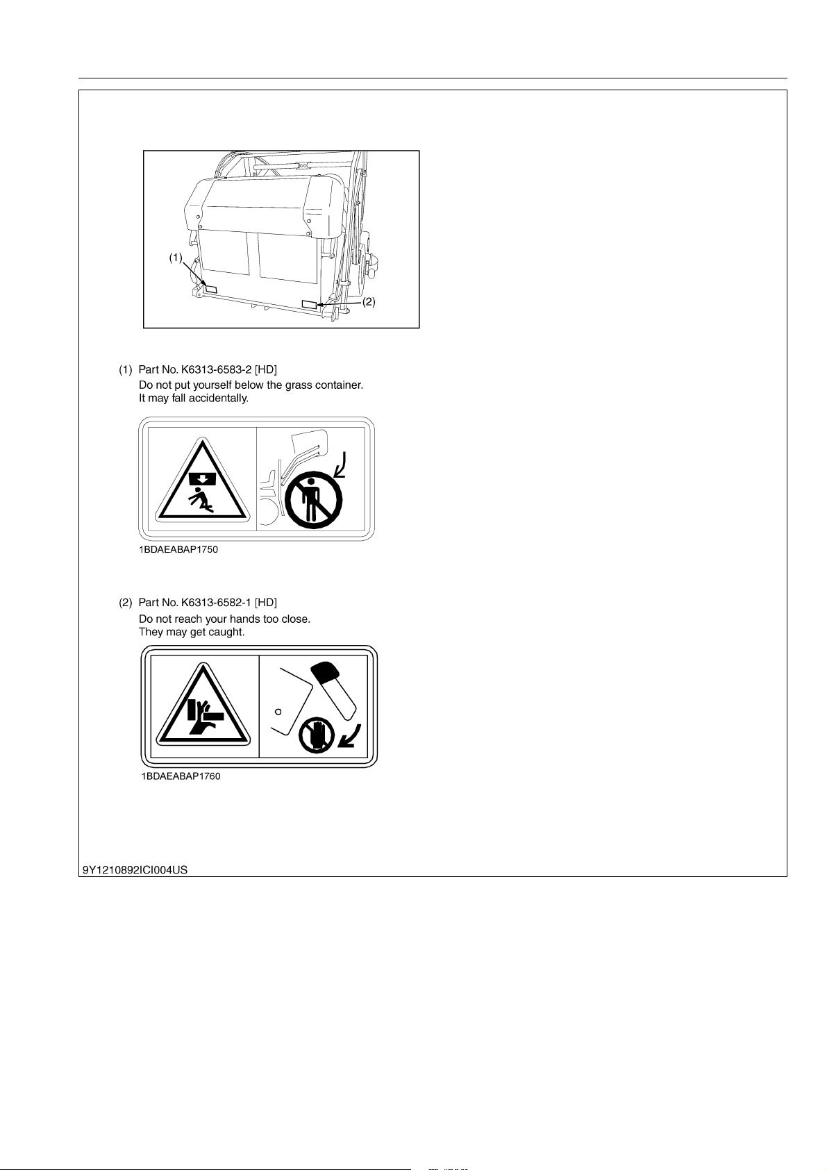
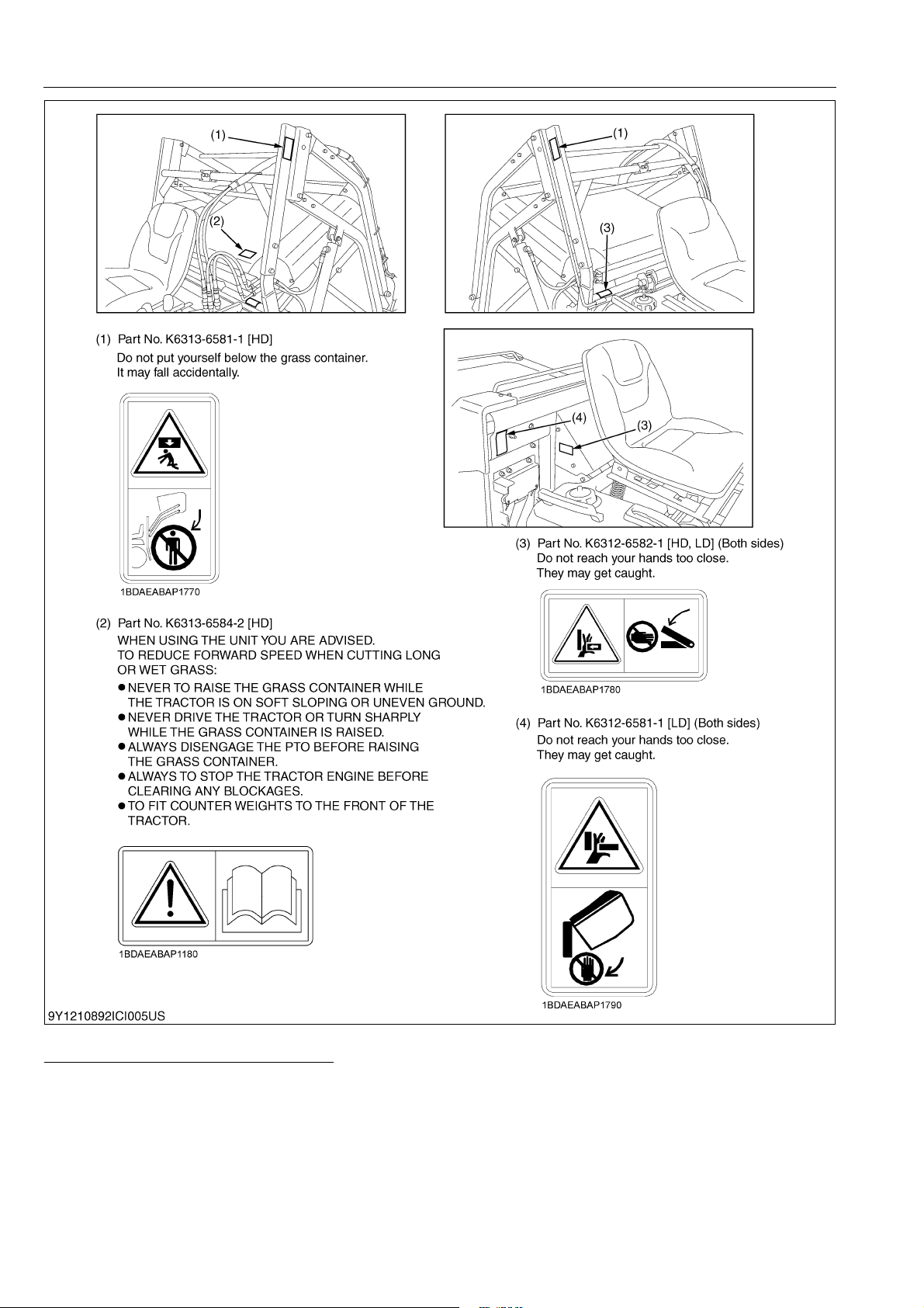
2. SAFETY DECALS
The following safety decals (pictorial safety labels) are installed on the machine. If a decal becomes
damaged, illegible or is not on the machine, replace it. The decal part number is listed in the parts list.
WSM000001INI0014US0
9Y1210892INI0001US0
I-4
Page 10
G23-2, G26-2, WSM
KiSC issued 02, 2014 A
INFORMATION
9Y1210892INI0002US0
I-5
Page 11
G23-2, G26-2, WSM
KiSC issued 02, 2014 A
INFORMATION
9Y1210892INI0003US0
I-6
Page 12
G23-2, G26-2, WSM
KiSC issued 02, 2014 A
INFORMATION
9Y1210892INI0004US0
I-7
Page 13
G23-2, G26-2, WSM
KiSC issued 02, 2014 A
INFORMATION
9Y1210892INI0005US0
CARE OF PICTORIAL SAFETY LABELS
1. Keep pictorial safety labels clean and free from obstructing material.
2. Clean pictorial safety labels with soap and water, dry with a soft cloth.
3. Replace damaged or missing pictorial safety labels with new labels.
4. If a component with pictorial safety label(s) affixed is replace with new part, make sure new label(s) is (are)
attached in the same location(s) as the replace component.
5. Mount new pictorial safety labels by applying on a clean dry surface and pressure any bubbles to outside edge.
9Y1210892INI0006US0
I-8
Page 14

G23-2, G26-2, WSM
NOTE
KiSC issued 02, 2014 A
3. SPECIFICATIONS
INFORMATION
Engine
Capacities
Machine
Dimensions
Mower
Grass
collector
Model
Model D902-E3-GT D1005-E3-GT
Type Liquid-cooled diesel
Total displacement 898 cm
Gross power 17.1 kW (23.3 HP) 18.8 kW (25.5 HP)
Number of cylinders 3
Starter Electric starter with battery
Battery 12V, RC: 80 min, CCA: 535A
Fuel
Preheating system Super glow
Engine stop Key stop
Fuel tank 20 L (5.3 U.S.gals, 4.4 Imp.gals)
Engine oil 3.1 L (3.3 U.S.qts, 2.7 Imp.qts) 3.5 L (3.7 U.S.qts, 3.1 Imp.qts)
Radiator coolant 3.1 L (3.3 U.S.qts, 2.7 Imp.qts) 3.3 L (3.5 U.S.qts, 2.9 Imp.qts)
Hydrostatic transmission oil 11 L (12 U.S.qts, 9.7 Imp.qts)
PTO Shaft drive
PTO clutch Belt tension Wet disks
PTO brake Shoe Wet disks
Tyres
Steering type Hydrostatic type power steering
Brakes Wet Discs
Travel speed control Foot pedal
Transmission Hydrostatic
Traveling
speeds
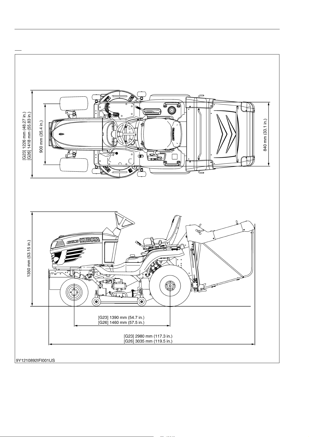
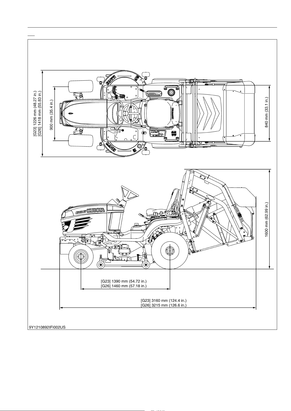
Overall length
(with grass collector), without
front weight bracket for HD
Overall width (with mower) 1226 mm (48.27 in.) 1418 mm (55.83 in.)
Overall height 1350 mm (53.15 in.) 1600 mm (62.99 in.) 1350 mm (53.15 in.) 1600 mm (62.99 in.)
Wheel base 1390 mm (54.72 in.) 1460 mm (57.18 in.)
Tyead
Weight (Without mower deck
and grass collector)
Model RCK48-G23-2 RCK54-G26-2
Cutting width 1219 mm (48.0 in.) 1372 mm (54.0 in.)
Cutting height 25 to 102 mm (1.0 to 4.0 in.)
Adjustment of cutting height Dial gauge
Mounting method Quick joint, parallel linkage
Weight (Approx.) 120 kg (265 lbs) 135 kg (298 lbs)
Dimensions
Discharge direction Rear
Gear box oil 1.9 L (2.0 U.S.qts, 1.7 Imp.qts) 2.1 L (2.2 U.S.qts, 1.8 Imp.qts)
Model GCK-G23LD GCK-G26HD
Container capacity 560 L (148 U.S.gals, 123 Imp.gals) 640 L (169 U.S.gals, 141 Imp.gals)
Weight (Approx.) 35 kg (77 lbs) 220 kg (485 lbs)
Front 16 × 7.50-8
Rear 24 × 12.00-12
Forward 0 to 15.5 km/h (0 to 9.6 mph) 0 to 17.0 km/h (0 to 10.6 mph)
Reverse 0 to 10.0 km/h (0 to 6.2 mph)
2980 mm (117.3 in.) 3160 mm (124.4 in.) 3035 mm (119.5 in.) 3215 mm (126.6 in.)
Front 900 mm (35.4 in.)
Rear 840 mm (33.1 in.)
Total length 895 mm (35.2 in.) 980 mm (38.6 in.)
Total width 1266 mm (49.8 in.) 1418 mm (55.8 in.)
Total height 400 mm (15.8 in.)
LD HD LD HD
535 kg (1180 lbs) 500 kg (1100 lbs) 565 kg (1250 lbs) 535 kg (1180 lbs)
G23-2 G26-2
3
(54.8 cu.in.) 1001 cm3 (61.1 cu.in.)
Diesel fuel No. 1 [below – 10 °C (14 °F)]
Diesel fuel No. 2 [above – 10 °C (14 °F)]
• The company reserves the right to change the specifications without notice.
9Y1210892INI0007US0
I-9
Page 15
G23-2, G26-2, WSM
KiSC issued 02, 2014 A
4. DIMENSIONS
LD
INFORMATION
9Y1210892INI0008US0
I-10
Page 16
G23-2, G26-2, WSM
KiSC issued 02, 2014 A
HD
INFORMATION
9Y1210892INI0009US0
I-11
Page 17

G GENERAL
KiSC issued 02, 2014 A
Page 18

GENERAL
KiSC issued 02, 2014 A
CONTENTS
1. MACHINE IDENTIFICATION........................................................................................................G-1
[1] SERIAL NUMBER .................................................................................................................. G-1
[2] CYLINDER NUMBER ............................................................................................................. G-2
2. GENERAL PRECAUTIONS.......................................................................................................... G-3
3. HANDLING PRECAUTIONS FOR ELECTRICAL PARTS AND WIRING .................................... G-4
[1] WIRING .................................................................................................................................. G-4
[2] BATTERY ............................................................................................................................... G-6
[3] FUSE ...................................................................................................................................... G-6
[4] CONNECTOR ........................................................................................................................ G-6
[5] HANDLING OF CIRCUIT TESTER ........................................................................................ G-7
[6] COLOR OF WIRING ..............................................................................................................G-8
4. LUBRICANTS, FUEL AND COOLANT......................................................................................... G-9
5. TIGHTENING TORQUES ........................................................................................................... G-12
[1] GENERAL USE SCREWS, BOLTS AND NUTS .................................................................. G-12
[2] STUD BOLTS ....................................................................................................................... G-12
[3] AMERICAN STANDARD SCREWS, BOLTS AND NUTS WITH UNC OR UNF
THREADS ............................................................................................................................ G-13
[4] PLUGS ................................................................................................................................. G-13
6. MAINTENANCE CHECK LIST ................................................................................................... G-14
7. CHECK AND MAINTENANCE ................................................................................................... G-16
[1] DAILY CHECK...................................................................................................................... G-16
(1) Walking Around the Machine.......................................................................................... G-16
(2) Mower............................................................................................................................. G-19
(3) While Sitting on the Operator's Seat .............................................................................. G-19
(4) Turning the Key Switch "ON".......................................................................................... G-19
(5) Starting the Engine ......................................................................................................... G-19
(6) Others............................................................................................................................. G-20
[2] CHECK POINTS OF INITIAL 50 HOURS ............................................................................ G-20
[3] CHECK POINTS OF EVERY 50 HOURS ............................................................................ G-22
[4] CHECK POINTS OF EVERY 100 HOURS .......................................................................... G-37
[5] CHECK POINT OF EVERY 150 HOURS ............................................................................. G-39
[6] CHECK POINTS OF EVERY 200 HOURS .......................................................................... G-40
[7] CHECK POINTS OF EVERY 400 HOURS .......................................................................... G-45
[8] CHECK POINT OF EVERY 1500 HOURS ........................................................................... G-46
[9] CHECK POINT OF EVERY 3000 HOURS ........................................................................... G-46
[10]CHECK POINT OF EVERY 1 YEAR .................................................................................... G-46
[11]CHECK POINTS OF EVERY 2 YEARS ............................................................................... G-47
.......
[12]OTHERS.......................................................................................................................
8. SPECIAL TOOLS ....................................................................................................................... G-55
[1] SPECIAL TOOLS FOR ENGINE .......................................................................................... G-55
[2] SPECIAL TOOLS FOR MACHINE ....................................................................................... G-60
9. TYRE PRESSURE AND WHEEL ............................................................................................... G-62
[1] TYRE PRESSURE ............................................................................................................... G-62
[2] WHEEL................................................................................................................................. G-62
10. IMPLEMENT LIMITATIONS ....................................................................................................... G-63
. G-51
Page 19
G23-2, G26-2, WSM
KiSC issued 02, 2014 A
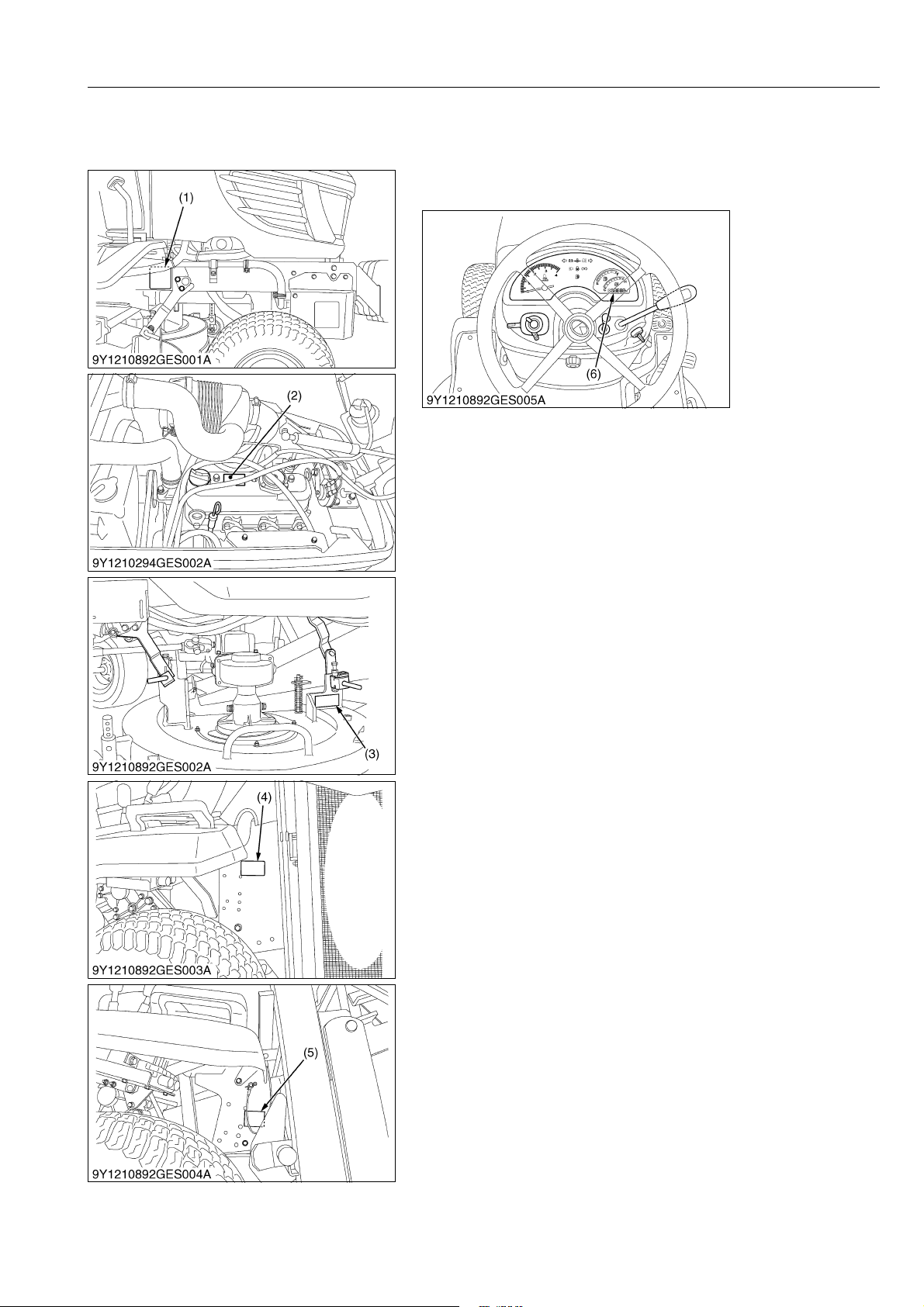
1. MACHINE IDENTIFICATION
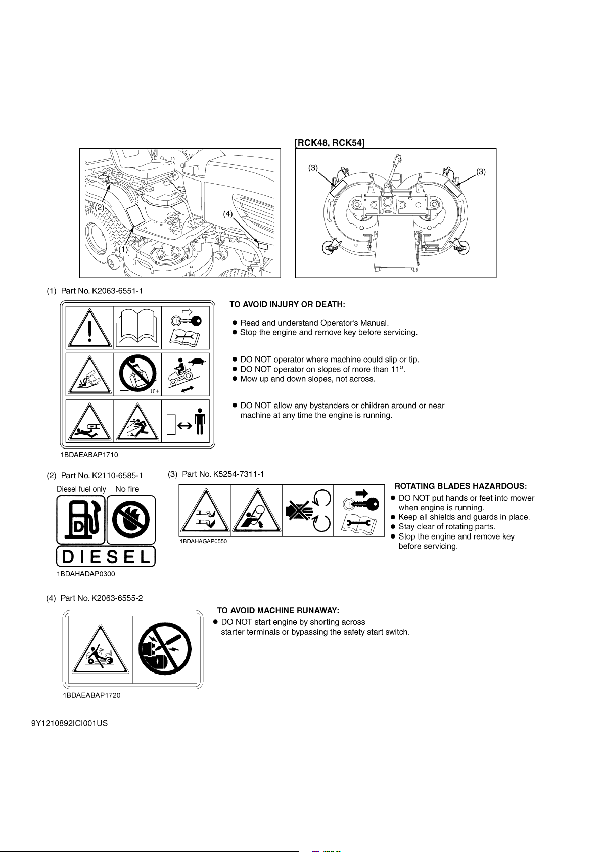
[1] SERIAL NUMBER
When contacting your local KUBOTA distributor, always specify
engine serial number, tractor serial number and hour meter reading.
GENERAL
(1) Machine Serial Number
(2) Engine Serial Number
(3) Mower Serial Number
(4) Grass Catcher Serial Number (LD)
(5) Grass Catcher Serial Number (HD)
(6) Hour Meter / Tachometer
9Y1210892GEG0001US0
G-1
Page 20

G23-2, G26-2, WSM
KiSC issued 02, 2014 A
[2] CYLINDER NUMBER
GENERAL
You can see the cylinder numbers of KUBOTA diesel engine in
the figure. The sequence of cylinder numbers is No. 1, No. 2 and
No. 3 and it starts from the gear case side.
WSM000001GEG0056US0
G-2
Page 21
G23-2, G26-2, WSM
KiSC issued 02, 2014 A
2. GENERAL PRECAUTIONS
• When you disassemble, carefully put the parts in a clean area
to make it easy to find the parts. You must install the screws,
bolts and nuts in their initial position to prevent the reassembly
errors.
• When it is necessary to use special tools, use KUBOTA special
tools. Refer to the drawings when you make special tools that
you do not use frequently.
• Before you disassemble or repair machine, make sure that you
always disconnect the ground cable from the battery first.
• Remove oil and dirt from parts before you measure.
• Use only KUBOTA genuine parts for replacement to keep the
machine performance and to make sure of safety.
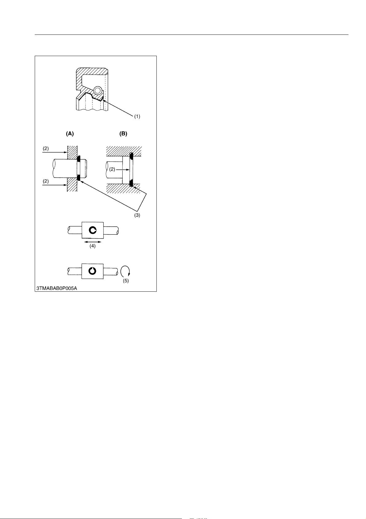
• You must replace the gaskets and O-rings when you assemble
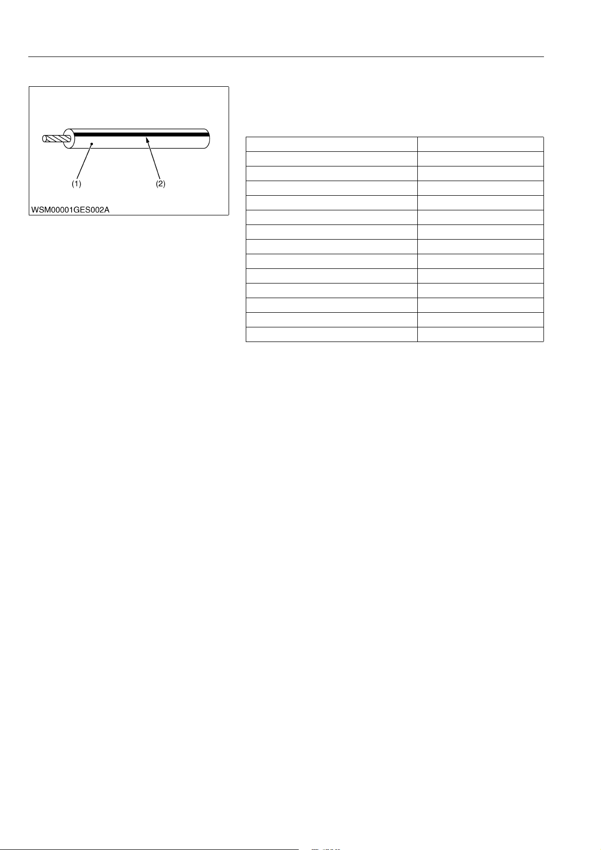
again. Apply grease (1) to new O-rings or oil seals before you
assemble.
• When you assemble the external or internal circlips, make sure
that the sharp edge (3) faces against the direction from which
force (2) is applied.
• When inserting spring pins, their splits must face the direction
from which a force is applied. See the figure on the left side.
• To prevent damage to the hydraulic system, use only specified
fluid or equivalent.
(1) Grease
(2) Force
(3) Sharp Edge
(4) Axial Force
(5) Rotating Movement
GENERAL
(A) External Circlip
(B) Internal Circlip
WSM000001GEG0092US0
G-3
Page 22
G23-2, G26-2, WSM
IMPORTANT
KiSC issued 02, 2014 A
GENERAL
3. HANDLING PRECAUTIONS FOR ELECTRICAL PARTS AND WIRING
To ensure safety and prevent damage to the machine and
surrounding equipment, obey the following precautions in handling
electrical parts and wiring.
• Check electrical wiring for damage and loosened
connection every year. To this end, educate the customer
to do his or her own check and at the same time
recommend the dealer to perform periodic check for a fee.
• Do not try to modify or remodel any electrical parts and
wiring.
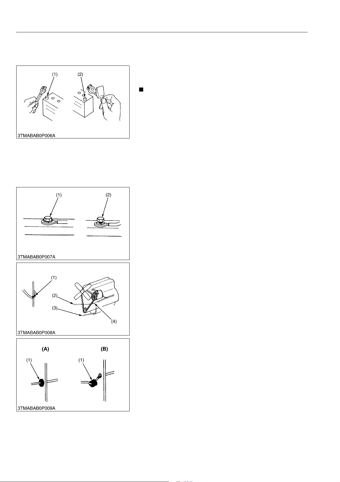
• When removing the battery cables, disconnect the negative
cable first. When installing the battery cables, connect the
positive cable first.
(1) Negative Terminal (2) Positive Terminal
WSM000001GEG0062US0
[1] WIRING
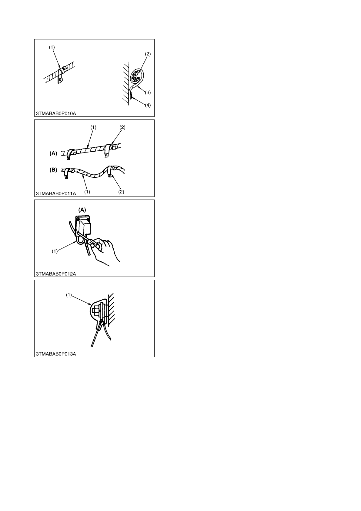
• Securely tighten wiring terminals.
(1) Correct
(Securely Tighten)
(2) Incorrect
(Loosening Leads to Faulty Contact)
WSM000001GEG0063US0
• Do not let wiring contact dangerous part.
(1) Dangerous Part (Sharp Edge)
(2) Wiring (Incorrect)
(3) Wiring (Correct)
(4) Dangerous Part
• Securely insert grommet.
(1) Grommet (A) Correct
(B) Incorrect
WSM000001GEG0064US0
WSM000001GEG0066US0
G-4
Page 23
G23-2, G26-2, WSM
KiSC issued 02, 2014 A
GENERAL
• Securely clamp, being careful not to damage wiring.
(1) Clamp
(Wind Clamp Spirally)
(2) Wire Harness
(3) Clamp
(4) Welding Dent
WSM000001GEG0067US0
• Clamp wiring so that there is no twist, unnecessary sag, or
excessive tension, except for movable part, where sag be
required.
(1) Wiring
(2) Clamp
(A) Correct
(B) Incorrect
WSM000001GEG0068US0
• In installing a part, be careful not to get wiring caught by it.
(1) Wiring (A) Incorrect
WSM000001GEG0069US0
• After installing wiring, check protection of terminals and
clamped condition of wiring.
(1) Cover
(Securely Install Cover)
WSM000001GEG0070US0
G-5
Page 24
G23-2, G26-2, WSM
CAUTION
KiSC issued 02, 2014 A
[2] BATTERY
GENERAL
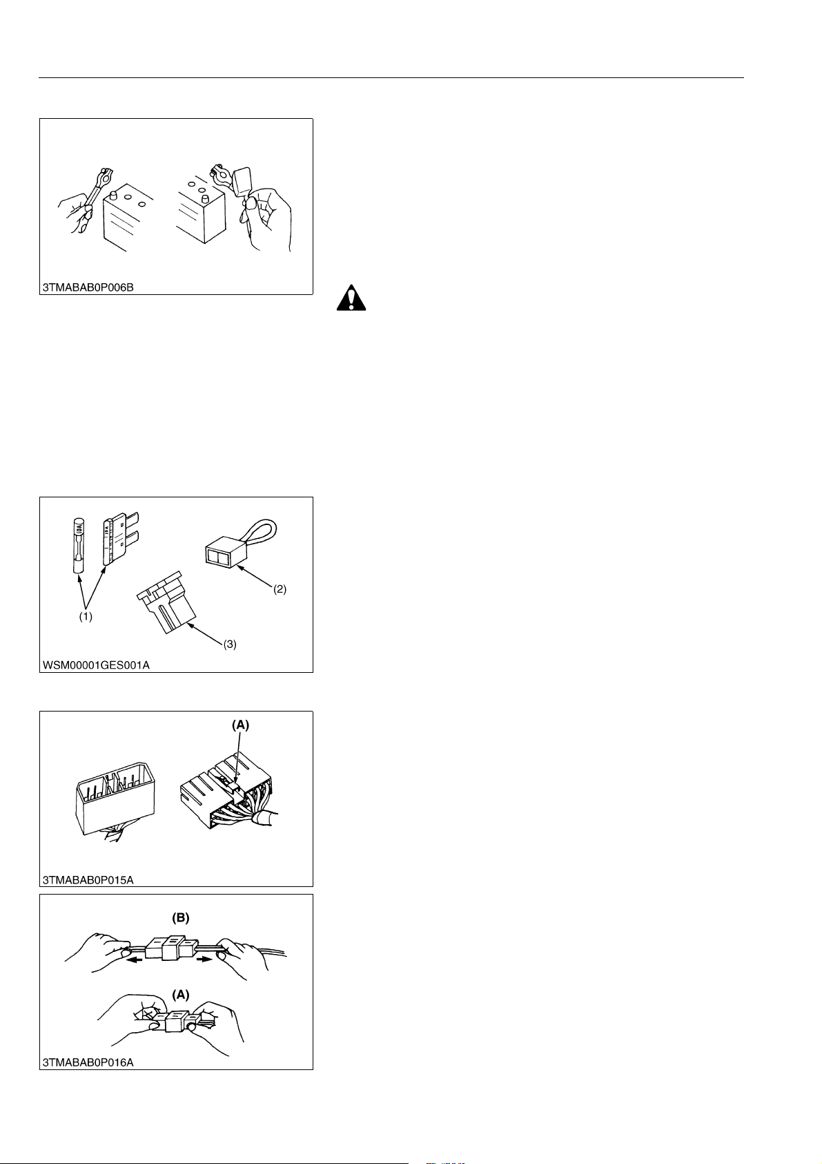
• Be careful not to confuse positive and negative terminal posts.
• When you remove battery cables, disconnect negative cable
first. When you install battery cables, check for polarity and
connect positive cable first.
• Do not install any battery with capacity other than is specified
(Ah).
• After you connect cables to battery terminal posts, apply high
temperature grease to them and securely install terminal covers
on them.
• Do not allow dirt and dust to collect on battery.
• Be careful not to let battery liquid spill on your skin and
clothes. If contaminated, wash it off with water
immediately.
• Before you recharge the battery, remove it from the
machine.
• Before you recharge, remove cell caps.
• Recharge in a well-ventilated place where there is no open
flame nearby, as hydrogen gas and oxygen are formed.
WSM000001GEG0071US0
[3] FUSE
[4] CONNECTOR
• Use fuses with specified capacity.
Neither too large nor small capacity fuse is acceptable.
• Never use steel nor copper wire in place of fuse.
• Do not install working light, radio set, etc. on machine which is
not provided with reserve power supply.
• Do not install accessories if fuse capacity of reserve power
supply is exceeded.
(1) Fuse
(2) Fusible Link
(3) Slow Blow Fuse
WSM000001GEG0072US0
• For connector with lock, push lock to separate.
(A) Push
WSM000001GEG0073US0
• In separating connectors, do not pull wire harnesses.
• Hold connector bodies to separate.
(A) Correct (B) Incorrect
WSM000001GEG0074US0
G-6
Page 25
G23-2, G26-2, WSM
KiSC issued 02, 2014 A
GENERAL
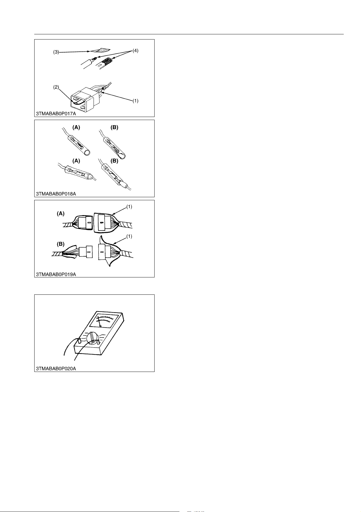
• Use sandpaper to remove rust from terminals.
• Repair deformed terminal. Make sure that there is no terminal
being exposed or displaced.
(1) Exposed Terminal
(2) Deformed Terminal
(3) Sandpaper
(4) Rust
WSM000001GEG0075US0
• Make sure that there is no female connector being too open.
(A) Correct (B) Incorrect
WSM000001GEG0076US0
• Make sure that plastic cover is large enough to cover whole
connector.
(1) Cover (A) Correct
(B) Incorrect
WSM000001GEG0077US0
[5] HANDLING OF CIRCUIT TESTER
• Use tester correctly following manual provided with tester.
• Check for polarity and range.
WSM000001GEG0078US0
G-7
Page 26
G23-2, G26-2, WSM
KiSC issued 02, 2014 A
[6] COLOR OF WIRING
GENERAL
• Colors of wire are specified to the color codes.
• This symbol of "/" shows color with stripe(s).
(An example)
Red stripe on white color: W/R
Color of wiring Color code
Black B
Brown Br
Green G
Gray Gy or Gr
Blue L
Light Green Lg
Orange Or
Pink P
Purple Pu or V
Red R
Sky Blue Sb
White W
Yellow Y
(1) Wire Color (2) Stripe
WSM000001GEG0079US0
G-8
Page 27

G23-2, G26-2, WSM
KiSC issued 02, 2014 A
4. LUBRICANTS, FUEL AND COOLANT
Capacities
No. Place
LD HD LD HD
1Fuel
Coolant
2
(with recovery tank)
3 Engine crankcase
4 Transmission case
5 Mower gear box
3.1 L
3.3 U.S.qts
2.7 Imp.qts
3.1 L*
3.3 U.S.qts
2.7 Imp.qts
1.9 L
2.0 U.S.qts
1.7 Imp.qts
20 L
5.3 U.S.gals
4.4 Imp.gals
3.3 L
3.5 U.S.qts
2.9 Imp.qts
3.5 L*
3.7 U.S.qts
3.1 Imp.qts
11 L
12 U.S.qts
9.7 Imp.qts
2.1 L
2.2 U.S.qts
1.8 Imp.qts
• No. 2-D diesel fuel
• No. 1-D diesel fuel if temperature
is below –10 °C (14 °F)
Fresh clean water with anti-freeze
Engine oil
API Service Classification CD, CE
or CF
• Above 25 °C (77 °F)
SAE30W,
SAE10W-30 or 15W-40
• 0 to 25 °C (32 to 77 °F)
SAE20, SAE10W-30 or 15W-40
• Below 0 °C (32 °F)
SAE10W,
SAE10W-30 or 15W-40
KUBOTA UDT or SUPER UDT fluid*
KUBOTA UDT or SUPER UDT fluid*
GENERAL
LubricantsG23-2 G26-2
G-9
Page 28
G23-2, G26-2, WSM
NOTE
IMPORTANT
KiSC issued 02, 2014 A
No. Place
Front axle (King pin) 2
Front axle (Centre pin) 1
Mower link 10
Brake pedal link 6
HST speed change pedal
dumper
HST pedal boss 1
Tension PTO arm 1
PTO (Spline) 1
Parking lock pedal link 2
Cruise control link 2
Differential lock pedal link 4
Under duct pivot 4
Sensor system pivot 2
Duct cleanup system link 4
Seat adjuster 2
Seat pivot 2
6
Throttle cable 1 Moderate amount Oil
Mower universal joint 3
Mower universal joint
(Grease fitting)
Mower lift cylinder 5
Mower lift arm front (RH) 1
Mower lift link front 3
Mower lift arm rear (LH, RH) 4
Mower lift pin front (LH, RH) 2
Mower lift link rear (LH, RH) 4
Dump cylinder 2–2–
Grass container rotation pivot4–4–
Lock lever (LH, RH) 2–2–
Grass container pivot
(Grease fitting) (LH, RH)
Grass container lift cylinder
(LH, RH)
Dump pivot (LH, RH) –2–2
Greasing
No. of greasing point
LD HD LD HD
2
2
–10–10
–4–4
Capacity Type of greaseG23-2 G26-2
Until grease overflows
Until grease overflows
GENERAL
Multipurpose EP2
grease
(NLGI Grade No.2)
Multipurpose EP2
grease
(NLGI Grade No.2)
• * Oil amount when the oil level is at the upper level of the oil lever gauge.
• Check the oil lever of the transmission case with the mower lifted up and grass catcher lowered.
• To prevent serious damage to hydraulic system, use only KUBOTA genuine fluid or its equivalent.
9Y1210892GEG0002US0
G-10
Page 29

G23-2, G26-2, WSM
NOTE
KiSC issued 02, 2014 A
GENERAL
Engine Oil
• Oil used in the engine should have an American Petroleum Institute (API) service classification and
Proper SAE Engine Oil according to the ambient temperatures as shown above :
• With the emission control now in effect, the CF-4 and CG-4 lubricating oils have been developed for use
of a low-sulfur fuel on on-road vehicle engines. When an off-road vehicle engine runs on a high-sulfur
fuel, it is advisable to employ the "CF or better" lubricating oil with a high Total Base Number (TBN of 10
minimum).
• Refer to the following table for the suitable API classification engine oil according to the engine type (with
internal EGR, external EGR or non-EGR) and the fuel (low-sulfur or high-sulfur fuel).
Fuel used
Engine oil classification (API classification)
Oil class of engines except external EGR Oil class of engines with external EGR
CF
High Sulfur Fuel
[≥ 0.05 % (500 ppm)]
(If the "CF-4, CG-4, CH-4, or CI-4"
lubricating oil is used with a high-sulfur
fuel, change the lubricating oil at shorter
—
intervals. (approximately half))
Low Sulfur Fuel
[< 0.05 % (500 ppm)] or
Ultra Low Sulfur Fuel
[< 0.0015 % (15 ppm)]
CF, CF-4, CG-4, CH-4 or CI-4
CF, CI-4
(Class CF-4, CG-4 and CH-4 engine oils
cannot be used on EGR type engines)
EGR: Exhaust Gas Re-circulation
• The CJ-4 engine oil is intended for DPF (Diesel Particulate Filter) Type engines, and cannot be used on
this machine.
except external EGR with external EGR
Models G23-2, G26-2 –
Fuel
• Cetane number of 45 minimum. Cetane number greater then 50 is preferred, especially for temperatures
below −20 °C (−4 °F) or elevations above 1500 m (5000 ft).
• If diesel fuel with sulfur content greater than 0.5 % (5000 ppm) sulfur content in used, reduce the service
interval for engine oil and filter by 50%.
• NEVER use diesel fuel with sulfur content greater than 0.05% (500 ppm) for EXTERNAL EGR type engine.
• DO NOT use diesel fuel with sulfur content greater than 1.0% (10000 ppm).
• Diesel fuels specified to EN 590 or ASTM D975 are recommended.
• No.2-D is a distillate fuel of lower volatility for engine in industrial and heavy mobile service. (SAE J313
JUN87)
Transmission oil
• The oil used to lubricate the transmission is also used as hydraulic fluid. To insure proper operation of
the hydraulic system and to complete lubrication of the transmission, it is important that a multi-grade
transmission fluid is used in this system. We recommend the use of KUBOTA UDT or SUPER UDT fluid
for optimum protection and performance.
Do not mix different brands together.
Indicated capacities of water and oil are manufacturer's estimate.
9Y1210892GEG0003US0
G-11
Page 30

G23-2, G26-2, WSM
KiSC issued 02, 2014 A
GENERAL
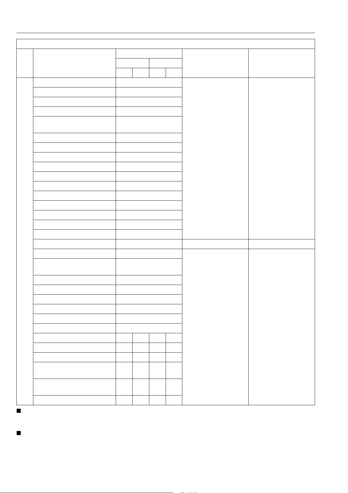
5. TIGHTENING TORQUES
[1] GENERAL USE SCREWS, BOLTS AND NUTS
Tighten screws, bolts and nuts whose tightening torques are not specified in this Workshop Manual
according to the table below.
Indication on top of bolt
Indication on top of nut
Material of opponent part Ordinariness Aluminum Ordinariness Aluminum Ordinariness
Unit N·m kgf·m lbf·ft N·m kgf·m lbf·ft N·m kgf·m lbf·ft N·m kgf·m lbf·ft N·m kgf·m lbf·ft
7.9
0.80
M6
M8
M10
M12
M14
M16
M18
M20
to
9.3
18
to
20
40
to
45
63
to
72
108
to
125
16
to
191
246
to
284
334
to
392
to
0.95
1.8
to
2.1
4.0
to
4.6
6.4
to
7.4
11. 0
to
12.8
7
17.0
to
19.5
25.0
to
29.0
34.0
to
40.0
No-grade or 4T 7T 9T
No-grade or 4T
5.8
7.9
0.80
5.8
9.81
1.00
7.24
7.9
0.80
5.8
to
to
to
1.7
to
2.0
3.2
to
3.5
to
6.5
13
to
14
24
to
25
6.8
8.8
0.90
13
17
to
to
15
19
32
29
to
to
33
34
47
to 53–––
79.6
to
92.5
–––
123
to
–––
141
181
to
–––
209
246
to
–––
289
to
11. 2
24
to
27
48
to
55
78
to
90
124
to
147
197
to
225
275
to
318
368
to
431
to
1.15
2.4
to
2.8
4.
9
to
5.7
7.9
to
9.2
12.6
to
15.0
20.0
to
23.0
28.0
to
32.5
37.5
to
44.0
to
8.31
18
to
20
36
to
41
58
to
66
91.2
to
108
145
to
166
203
to
235
272
to
318
to
to
8.8
0.90
18
1.8
to
to
20
2.1
40
4.0
to
to
44
4.5
63
6.4
to
to
72
7.4
––
–––
–––
–––
12.3
to
to
6.5
14.2
13
30
to
to
15
34
29
61
to
to
32
70
47
103
to
to
53
117
167
–
to
196
260
to
304
344
to
402
491
to
568
WSM000001GEG0001US0
6T
1.25
to
1.45
3.0
to
3.5
6.2
to
7.2
10.5
to
12.0
17.0
to
20.0
26.5
to
31.0
35.0
to
41.0
50.0
to
58.0
9.05
to
10.4
22
to
25
45
to
52
76.0
to
86.7
123
to
144
192
to
224
254
to
296
362
to
419
[2] STUD BOLTS
Material of opponent part Ordinariness Aluminum
Unit N·m kgf·m lbf·ft N·m kgf·m lbf·ft
12
1.2
8.7
M8
M10
M12
M14
M16
M18
to
15
25
to
31
30
to
49
62
to
73
98.1
to
112
172
to
201
to
1.6
2.5
to
3.2
3.0
to
5.0
6.3
to
7.5
10.0
to
11. 5
17.5
to
20.5
8.9
to
to
11
11
18
20
to
to
23
25
22
to 3631 3.2 23
46
to 54–––
72.4
to
83.1
–––
127
to
–––
148
0.90
to
1.2
2.0
to
2.6
6.5
to
8.6
15
to
18
WSM000001GEG0002US0
G-12
Page 31

G23-2, G26-2, WSM
KiSC issued 02, 2014 A
GENERAL
[3] AMERICAN STANDARD SCREWS, BOLTS AND NUTS WITH
UNC OR UNF THREADS
Grade
Unit N·m kgf·m lbf·ft N·m kgf·m lbf·ft
1/4 11.7 to 15.7 1.20 to 1.60 8.63 to 11.5 16.3 to 19.7 1.67 to 2.00 12.0 to 14.6
5/16 23.1 to 27.7 2.36 to 2.82 17.0 to 20.5 33 to 39 3.4 to 3.9 25 to 28
3/8 48 to 56 4.9 to 5.7 36 to 41 61 to 73 6.3 to 7.4 45 to 53
1/2 110 to 130 11.3 to 13.2 81.2 to 95.8 150 to 178 15.3 to 18.1 111 to 131
9/16 150 to 178 15.3 to 18.1 111 to 131 217 to 260 22.2 to 26.5 160 to 191
5/8 204 to 244 20.8 to 24.8 151 to 179 299 to 357 30.5 to 36.4 221 to 263
SAE GR.5 SAE GR.8
WSM000001GEG0008US0
[4] PLUGS
Material of opponent part
Shape Size
N·m kgf·m lbf·ft N·m kgf·m lbf·ft
Tapered screw
Straight screw G1/4 25 to 34 2.5 to 3.5 18 to 25 – – –
R1/8 13 to 21 1.3 to 2.2 9.4 to 15 13 to 19 1.3 to 2.0 9.4 to 14
R1/4 25 to 44 2.5 to 4.5 18 to 32 25 to 34 2.5 to 3.5 18 to 25
R3/8 49 to 88 5.0 to 9.0 37 to 65 49 to 58 5.0 to 6.0 37 to 43
R1/2 58.9 to 107 6.00 to 11.0 43.4 to 79.5 59 to 78 6.0 to 8.0 44 to 57
G3/8 62 to 82 6.3 to 8.4 46 to 60 – – –
Ordinariness Aluminum
G1/2 49 to 88 5.0 to 9.0 37 to 65 – – –
WSM000001GEG0005US0
G-13
Page 32

G23-2, G26-2, WSM
KiSC issued 02, 2014 A
6. MAINTENANCE CHECK LIST
GENERAL
Indication on hour meter
No. Item
1 Engine oil Change
2 Engine oil filter Replace
3 Transmission fluid Change
4 Transmission oil filter Replace
5 Transmission strainer Clean
6 Front axle pivot Adjust
7 Engine start system Check
8 OPC system Check
9 PTO control system Check
10 Oiling –
11 Greasing –
Check
12 Mower gear box oil
Change
Clean
13 Air cleaner element
Replace
14 Battery condition Check
15 Front PTO belt tension Adjust
16 Brake Check
17
Fan dr
ive belt Check
18 HST neutral spring Adjust
Check
19 Fuel filter element
Replace
Check
20 Fuel line
Replace
Check
21 Hydraulic hose
Replace
Check
22 Radiator hose and clamp
Replace
Check
23 Intake air line
Replace
50 100 150 200 250 300 350 400 450 500 550 600
200 Hr
200 Hr
400 Hr
200 Hr
400 Hr
200 Hr
150 Hr
1 year
100 Hr
100 Hr
100 Hr
100 Hr
400 Hr
100 Hr
2 years
200 Hr
2 years
200 Hr
2 years
200 Hr
2 years
After
since
every
every
every
every
every
every
every
50 Hr
every
50 Hr
every
50 Hr
every
50 Hr
every
50 Hr
every
50 Hr
every
every
50 Hr
every
every
50 Hr
every
50 Hr
every
every
every
every
every
every
every
every
every
every
every
every
every
Refer-
ence
page
G-40
G-40
G-45
G-41
G-46
G-41 *2
G-22
G-23
G-24
G-24
G-25
G-32
G-39
G-33 *1
G-46
G-34
G-36 *4
G-38 *2
G-37 *2
G-37
G-39
G-46 *2
G-39
G-47 *2
G-42
G-47 *2
G-44
G-47 *2
G-44
G-48 *3
Impor-
tant
G-14
Page 33

G23-2, G26-2, WSM
IMPORTANT
KiSC issued 02, 2014 A
GENERAL
No. Item
24 Toe-in Adjust
Fuel injection nozzle
25
(injection pressure)
26 Injection pump Check
27 Radiator Clean
28 Coolant Change
29 Anti-Freeze –
30 Mower gear box oil seal Replace
31 Engine breather hose Replace
32 Fuel system Bleed
33 Fuse Replace G-52
34 Blade Replace G-53
35 Light Bulb Replace G-54
36 Jump plate Check G-51
Check
50 100 150 200 250 300 350 400 450 500 550 600
Indication on hour meter
200 Hr
1500 Hr
3000 Hr
2 years
2 years
2 years
2 years
2 years
Service
as Re-
quired
After
since
every
every
every
every
every
every
every
every
Refer-
ence
page
G-45
G-46
G-46
G-49
G-49
G-49
G-48 *2
G-47
G-51
• The jobs indicated by must be done initially.
• *1: This maintenance should be done daily more often in dusty condition than in normal conditions.
Suggested cleaning interval is every 100 hours in normal conditions.
*2: Replace only if necessary.
*3: Initial elongation of the front PTO belt may occur prior to 25 hours.
Adjust the tension spring length as needed to maintain belt tension.
9Y1210892GEG0004US0
Impor-
tant
G-15
Page 34

G23-2, G26-2, WSM
CAUTION
CAUTION
CAUTION
IMPORTANT
KiSC issued 02, 2014 A
GENERAL
7. CHECK AND MAINTENANCE
• Be sure to check and service the machine on a level surface with the engine shut off and the parking brake
"ON" and implement lowered to the ground.
9Y1210892GEG0005US0
[1] DAILY CHECK
To prevent trouble from occurring, it is important to know the condition of the machine. Check it before starting.
To avoid personal injury :
• Be sure to check and service the machine on a level surface with the engine shut off, the ley removed and
the parking brake securely set.
9Y1210892GEG0006US0
(1) Walking Around the Machine
1. Tyre pressure, wear and damage.
2. Oil and water leak.
3. Engine oil level.
4. Transmission fluid level.
5. Coolant level in the recovery tank.
6. Damage of machine body, tightness of all bolts and nuts.
7. Radiator screen.
8. Panel screen.
9. Brake free travel.
10. Fuel level.
11. Check air cleaner.
9Y1210892GEG0007US0
Checking Engine Oil Level
To avoid personal injury :
• Be sure to stop the engine before checking the oil level.
1. Park the machine on a flat surface.
2. Check engine oil before starting the engine or 5 minutes or more
after the engine has stopped.
3. To check the oil level, draw out the dipstick, wipe it clean,
replace it, and draw it out again. Check to see that the oil level
lines between the two notches.
If the level is too low, add new oil to the prescribed level at the
oil inlet. (Refer to "4. LUBRICANTS, FUEL AND COOLANT" on
page G-9.)
• When using an oil of different maker or viscosity from the
previous one, remove all of the old oil and oil filter.
Never mix two different types of oil.
• If oil level is low, do not run the engine.
(1) Oil Inlet
(2) Dipstick
A: Oil level is acceptable within this
range.
9Y1210892GEG0008US0
G-16
Page 35

G23-2, G26-2, WSM
CAUTION
IMPORTANT
NOTE
KiSC issued 02, 2014 A
GENERAL
Checking and Refueling
To avoid personal injury :
• Do not smoke while refueling.
• Be sure to stop the engine and remove the key before
refueling.
• Handle fuel carefully. If the engine is running, do not fill the
fuel tank. If engine is hot, let engine cool several minutes
before adding fuel. Do not smoke while filling the fuel tank
or servicing the fuel system. Fill fuel tank only to bottom of
filler neck.
• To avoid allergic skin reaction: Wash hands immediately
after contact with diesel fuel.
1. Turn the key switch to "ON", check the amount of fuel by fuel
gauge.
2. Fill fuel tank when fuel gauge shown 1/4 or less fuel in tank.
3. Use grade No.2-Diesel fuel at the temperature above −10 °C
(14 °F).
Use grade No.1-Diesel fuel at the temperature below −10 °C
(14 °F).
20 L
Fuel tank Capacity
5.3 U.S.gals
4.4 Imp.gals
• Do not permit dirt or trash to get into the fuel system.
• Be careful not to let the fuel tank become empty, otherwise
air will enter the fuel system, necessitating bleeding before
next engine start.
• Be careful not to spill during refueling. If should spill, wipe
it off at once, or it may cause a fire.
• To prevent condensation (water) accumulation in the fuel
tank, fill the tank before parking overnight.
• No2-D is a distillate fuel of lower volatility for engines in
industrial and heavy mobile service. (SAE J313 JUN87)
• Grade of Diesel Fuel Oil according to ASTM D975
Water and
Flash point °C
Min Max Max Max
52 0.05 0.35 0.01
Distillation
temperatures
°C 90 %
point
Min Max Min Max Min Max Max Max Min
282 338 1.9 4.1 32.6 40.1 0.50 No.3 40
sediment,
volume %
Viscosity
kinematic cSt
or mm
at 40 °C
2
/s
Carbon residue
on, 10 percent
residuum, %
Viscosity
saybolt,
SUS
at 37.8 °C
Sulfur
weight
%
Ash, weight %
Cop
per
strip
corro-
sion
Cetane
number
(1) Fuel Tank Cap
9Y1210892GEG0009US0
G-17
Page 36

G23-2, G26-2, WSM
CAUTION
NOTE
IMPORTANT
WARNING
CAUTION
KiSC issued 02, 2014 A
GENERAL
Checking and Cleaning Panel and Radiator Screen
To avoid personal injury :
• Be sure to stop the engine and remove the key before
removing the screen.
1. Check the panel screens to be sure they are clean from debris.
2. Remove the lower panel plate.
• If the dust or chaff is accumulated in the battery
compartment, clean it thoroughly.
3. Detach the radiator screen, and then remove all the foreign
material.
• Panel and radiator screen must be clean from debris to
prevent engine from overheating and to allow good air
intake for air cleaner.
• Be sure to reinstall the panel on the pillar completely to
prevent the invasion of dust.
• Be sure to stop the engine to avoid personal injury and to
allow good air intake for air cleaner.
(1) Panel
(2) Knob
(3) Centre Pillar
(4) Radiator Screen
A: Remove
9Y1210892GEG0010US0
Checking Tyre Pressure
To avoid personal injury :
• Do not attempt to mount a tyre on a rim. This should be
done by a qualified person with the proper equipment.
• Always maintain the correct tyre pressure.
Do not inflate tyres above the recommended pressure
shown in the Operator's Manual.
• Inflation pressure in front tyres rises quickly when using
compressed air.
Never operate machine with a loose rim, wheel, or axle.
• Whenever bolts are loosened, retighten to specified torque.
• Check all bolts frequently and keep them tightened.
Inflation Pressure
Though the inflation pressure is factory-set to the prescribed
level, it naturally drops slowly in the course of time. Thus, check it
everyday and inflate as necessary.
Tyr e S i z es
Front 16 × 7.50-8, Turf
Rear 24 × 12.00-12, Turf
(1) Ground (A) Insufficient
(B) Normal
(C) Excessive
Recommended Inflation
Max. Pressure
2
120 kPa (1.2 kgf/cm
17.4 psi)
100 kPa (1.0 kgf/cm
14.5 psi)
9Y1210892GEG0011US0
,
2
,
G-18
Page 37

G23-2, G26-2, WSM
IMPORTANT
CAUTION
IMPORTANT
KiSC issued 02, 2014 A
GENERAL
Checking Transmission Fluid Level
1. Park the machine on a flat surface, raise the mower and lower
the grass catcher and shut off engine.
2. To check the oil level, draw out the dipstick (2), wipe it clean,
replace it, and draw it out again. Check to see that the oil level
lies between the two notches. If the level is too low, add new oil
to the prescribed level at the oil inlet (1). (Refer to "4.
LUBRICANTS, FUEL AND COOLANT" on page G-9.)
• If oil level is low, do not run the engine.
(1) Oil Inlet
(2) Dipstick
A: Oil level is acceptable within this
range.
9Y1210892GEG0012US0
Checking Coolant Level
To avoid personal injury :
• Be sure to stop the engine and remove the key before
checking coolant level.
• Do not remove the radiator cap while coolant is hot. When
cool, slowly rotate cap to the first stop and allow sufficient
time for excess pressure to escape before removing the
cap completely.
1. Check to see that the coolant level is between the Highest level
and Lowest level marks of recovery tank (1).
2. When the coolant level drops due to evaporation, add water
only. In case of leakage, add anti-freeze and water in the
specified mixing ratio up to the Highest level.
(See page G-49.)
• If the radiator cap has to be removed, follow the caution
above and securely retighten the cap.
• Use clean, distilled water and anti-freeze to fill the radiator.
(1) Recovery Tank A: Highest Level
(2) Mower
1. Oil leak.
2. Make sure blade cap screws are tight.
3. Blade wear or damage.
4. Check all hardware.
5. Make sure all pins are in place.
6. Mower deck cleaning.
(3) While Sitting on the Operator's Seat
1. Speed control pedal and brake pedal.
2. Brake lock.
(4) Turning the Key Switch "ON"
1. Performance of the easy checker light.
(5) Starting the Engine
1. Color of the exhaust fumes.
2. Safety start switch, seat safety control and another safety devices.
3. Check for abnormal noise and vibration.
B: Lowest Level
9Y1210892GEG0013US0
9Y1210892GEG0014US0
9Y1210892GEG0015US0
9Y1210892GEG0016US0
9Y1210892GEG0017US0
G-19
Page 38

G23-2, G26-2, WSM
CAUTION
IMPORTANT
KiSC issued 02, 2014 A
(6) Others
1. Check the areas where previous trouble was experienced.
[2] CHECK POINTS OF INITIAL 50 HOURS
Changing Engine Oil
To avoid personal injury :
• Be sure to stop the engine and remove the key before
changing the oil.
• Allow engine to cool down sufficiently; oil can be hot and
may cause burns.
1. To drain the used oil, remove the drain plug at the bottom of the
engine and drain the oil completely into the oil pan.
All the used oil can be drained out easily when the engine is still
warm.
2. After draining, reinstall the drain plug (3).
3. Fill with the new oil up to the upper notch on the dipstick (2).
(Refer to "4. LUBRICANTS, FUEL AND COOLANT" on page
G-9.)
Oil capacity with filter
G23
G26
GENERAL
9Y1210892GEG0018US0
3.1 L
3.3 U.S.qts
2.7 Imp.qts
3.5 L
3.7 U.S.qts
3.1 Imp.qts
• When using an oil of different maker or viscosity from the
previous one, remove all of the old oil and oil filter.
Never mix two different types of oil.
• If oil level is low, do not run the engine.
(1) Oil Inlet
(2) Dipstick
(3) Drain Plug
(4) Front Tyre (LH)
A: Oil lever is acceptable within this
range.
9Y1210892GEG0019US0
G-20
Page 39

G23-2, G26-2, WSM
CAUTION
IMPORTANT
CAUTION
IMPORTANT
KiSC issued 02, 2014 A
GENERAL
Replacing Engine Oil Filter
To avoid personal injury :
• Be sure to stop the engine and remove the key before
changing the oil and the oil filter.
• Allow engine to cool down sufficiently; oil can be hot and
may cause burns.
1. Remove the oil filter.
2. Put a film of clean engine oil on the rubber seal of the new filter.
3. Tighten the filter quickly until contacts the mounting surface.
Tighten filter by hand an additional 1/2 turn only.
4. After new filter has been replaced, the engine oil normally
decreases a little. Make sure that the engine oil does not leak
through the seal and be sure to check the oil level on the
dipstick. Then, fill the engine oil up to the prescribed level.
5. Properly dispose of used oil.
• To prevent serious damage to the engine, use only a
KUBOTA genuine filter.
(1) Engine Oil Filter
9Y1210892GEG0020US0
Replacing Transmission Oil Filter
To avoid personal injury :
• Allow engine to cool down sufficiently; oil can be hot and
can burn.
1. Remove the oil filter.
2. Put a film of clean transmission oil on rubber seal of new filter.
3. Tighten the filter quickly until contacts the mounting surface.
Tighten filter by hand an additional 1/2 turn only.
4. After the new filter has been replaced, the transmission fluid
level will decrease a little. Make sure that the transmission fluid
does not leak through the seal, and check the fluid level.
Top off if necessary.
5. Properly dispose of used oil.
• To prevent serious damage to the hydraulic system, use
only a KUBOTA genuine filter.
(1) Transmission Oil Filter
9Y1210892GEG0021US0
G-21
Page 40

G23-2, G26-2, WSM
CAUTION
CAUTION
IMPORTANT
KiSC issued 02, 2014 A
Changing Gear Box Oil
To avoid personal injury :
• Be sure to stop the engine and remove the key before
changing the oil.
• Remove the right and left hand shields from the mower
deck.
1. To drain the used oil, remove the oil level dipstick and the drain
plugs (2) at the gear box, tilt the mower deck and drain the oil
completely into the oil pan.
2. Reinstall the drain plugs (2). (Refer to "4. LUBRICANTS, FUEL
AND COOLANT" on page G-9.)
3. Fill with the new oil.
4. After filling, reinstall the oil level dipstick (1).
(1) Oil level Dipstick (2) Drain Plug
[3] CHECK POINTS OF EVERY 50 HOURS
Checking Engine Start System
The Engine Start System in your machine are designed to
protect you while operating. Please check these Engine Start
System periodically - daily is best - to test function of the Engine
Start System before operation.
GENERAL
9Y1210892GEG0022US0
To avoid personal injury:
• Do not allow anyone near the machine while testing.
• If the machine does not pass one of the following tests, do
not operate the machine.
• Check the following tests before operating the machine.
1. Check the following tests before operating the mower. Sit on the
operator's seat for all tests.
2. If the machine does not pass one of the following tests, do not
operate the machine.
Safety Start Control 1
1. Depress the brake pedal (5) fully.
2. Engage the PTO clutch lever (2).
3. Turn the key switch (1) to the "START" position.
4. The engine should not crank.
Safety Start Control 2
1. Disengage the PTO clutch lever (2).
2. Release the brake pedal (5).
3. Turn the key (1) to the "START" position.
4. The engine should not crank.
(1) Key Switch
(2) PTO Clutch Lever
(3) Operator's Seat
(4) Hand Throttle Lever
(5) Brake Pedal
(6) Hydraulic Container Dump Lever
9Y1210892GEG0023US0
G-22
Page 41

G23-2, G26-2, WSM
CAUTION
IMPORTANT
KiSC issued 02, 2014 A
GENERAL
Checking OPC System
The OPC (Operator Presence Control) system in your machine
are designed to protect you while operating. Please check these
OPC system periodically - daily is best - to test function of the OPC
system before operation.
To avoid personal injury:
• Do not allow anyone near the machine while testing.
• If the machine does not pass one of the following tests, do
not operate the machine.
• Check the following tests before operating the machine.
1. Check the following tests before operating the mower. Sit on the
operator's seat for all tests.
2. If the machine does not pass one of the following tests, do not
operate the machine.
Seat Safety Control 1
1. Run the engine at half throttle.
2. Engage the PTO clutch lever (2).
3. Stand up. (DO NOT GET OFF THE MACHINE.)
4. Engine should shut off.
Seat Safety Control 2
1. Run the engine at half throttle.
2. Disengage the PTO clutch lever (2).
3. Release the brake pedal (5).
4. Stand up. (DO NOT GET OFF THE MACHINE.)
5. Engine should shut off.
(1) Key Switch
(2) PTO Clutch Lever
(3) Operator's Seat
(4) Hand Throttle Lever
(5) Brake Pedal
(6) Hydraulic Container Dump Lever
9Y1210892GEG0080US0
G-23
Page 42

G23-2, G26-2, WSM
CAUTION
IMPORTANT
CAUTION
KiSC issued 02, 2014 A
GENERAL
Checking PTO Control System
The PTO control system in your machine are designed to
protect you while operating. Please check these PTO control
system periodically - daily is best - to test function of the PTO control
system before operation.
To avoid personal injury:
• Do not allow anyone near the machine while testing.
• If the machine does not pass one of the following tests, do
not operate the machine.
• Check the following tests before operating the machine.
1. Check the following tests before operating the mower. Sit on the
operator's seat for all tests.
2. If the machine does not pass one of the following tests, do not
operate the machine.
PTO Safety Control 1
1. Dismount the container from the platform.
2. Run the engine at half throttle.
3. Engage the PTO clutch lever (2).
4. Engine should shut off.
PTO Safety Control 2
1. Run the engine at half throttle.
2. Engage the PTO clutch lever (2).
3. Dump or lift up the grass catcher with the hydraulic container
dump lever (6).
4. Engine should shut off.
(1) Key Switch
(2) PTO Clutch Lever
(3) Operator's Seat
(4) Hand Throttle Lever
(5) Brake Pedal
(6) Hydraulic Container Dump Lever
9Y1210892GEG0081US0
Oiling
To avoid personal injury :
• Be sure to stop the engine and remove the key before
greasing.
1. Oil the location shown in the figures.
(1) Throttle Cable (G23)
(2) Throttle Cable (G26)
[A] G23
[B] G26
9Y1210892GEG0024US0
G-24
Page 43

G23-2, G26-2, WSM
CAUTION
KiSC issued 02, 2014 A
GENERAL
Greasing 1
To avoid personal injury :
• Be sure to stop the engine and remove the key before
greasing.
1. Apply a grease to the following positions as figures.
(1) Front Axle (King Pin)
(2) Front Axle (Center Pin)
(3) Middle Link (LH, RH)
(4) Brake Pedal Link
(5) Brake Pedal Link
9Y1210892GEG0025US0
G-25
Page 44

G23-2, G26-2, WSM
CAUTION
KiSC issued 02, 2014 A
GENERAL
Greasing 2
To avoid personal injury :
• Be sure to stop the engine and remove the key before
greasing.
1. Apply a grease to the following positions as figures.
(1) Brake Pedal Link
(2) HST Speed Change Pedal Dumper
(3) HST Speed Change Pedal Dumper
(4) HST Pedal Boss
(5) Tension PTO Arm
9Y1210892GEG0026US0
G-26
Page 45

G23-2, G26-2, WSM
CAUTION
KiSC issued 02, 2014 A
GENERAL
Greasing 3
To avoid personal injury :
• Be sure to stop the engine and remove the key before
greasing.
1. Apply a grease to the following positions as figures.
(1) PTO (Spline)
(2) Parking Lock Pedal Link
(3) Cruise Control Link
(4) Differential Lock Pedal Link
9Y1210892GEG0027US0
G-27
Page 46

G23-2, G26-2, WSM
CAUTION
KiSC issued 02, 2014 A
GENERAL
Greasing 4
To avoid personal injury :
• Be sure to stop the engine and remove the key before
greasing.
1. Apply a grease to the following positions as figures.
(1) Differential Lock Pedal Link
(2) Rear Tyre (LH)
(3) Under Duct Pivot
(4) Sensor System Pivot
(5) Duct Cleanup System Link
(6) Duct Cleanup System Link
(7) Seat Adjuster
9Y1210892GEG0028US0
G-28
Page 47

G23-2, G26-2, WSM
CAUTION
KiSC issued 02, 2014 A
GENERAL
Greasing 5
To avoid personal injury :
• Be sure to stop the engine and remove the key before
greasing.
1. Apply a grease to the following positions as figures.
(1) Seat Pivot
(2) Mower Universal Joint
(3) Mower Universal Joint
(Grease Fitting)
(4) Mower Lift Cylinder
(5) Mower Lift Cylinder
(6) Mower Lift Arm Front (RH)
9Y1210892GEG0029US0
G-29
Page 48

G23-2, G26-2, WSM
CAUTION
KiSC issued 02, 2014 A
GENERAL
Greasing 6
To avoid personal injury :
• Be sure to stop the engine and remove the key before
greasing.
1. Apply a grease to the following positions as figures.
(1) Mower Lift Link Front
(2) Mower Lift Arm Rear (LH, RH)
(3) Mower Lift Pin Front (LH, RH)
(4) Mower Lift Link Rear (LH, RH)
(5) Dump Cylinder (LD)
9Y1210892GEG0030US0
G-30
Page 49

G23-2, G26-2, WSM
CAUTION
KiSC issued 02, 2014 A
GENERAL
Greasing 7
To avoid personal injury :
• Be sure to stop the engine and remove the key before
greasing.
1. Apply a grease to the following positions as figures.
(1) Dumper Cylinder (LD)
(2) Grass Container Rotation Pivot (LD)
(3) Lock Lever (LD) (LH, RH)
(4) Grass Container Pivot
(Grease Fitting) (HD) (LH, RH)
(5) Grass Container Lift Cylinder (HD)
(LH, RH)
9Y1210892GEG0031US0
G-31
Page 50

G23-2, G26-2, WSM
CAUTION
CAUTION
NOTE
IMPORTANT
KiSC issued 02, 2014 A
GENERAL
Greasing 8
To avoid personal injury :
• Be sure to stop the engine and remove the key before
greasing.
1. Apply a grease to the following positions as figures.
(1) Dump Pivot (HD) (LH, RH)
9Y1210892GEG0032US0
Checking Gear Box Oil Level
To avoid personal injury :
• Always stop the engine and remove the key before
checking oil.
1. Park the machine on a flat surface and lower the mower to the
ground.
To check the oil level, draw out the dipstick, wipe it clean,
replace it, and draw it out again. Check to see that the oil level
lies between the two notches.
If the level is too low, add new oil to the prescribed level at the
oil inlet. (Refer to "4. LUBRICANTS, FUEL AND COOLANT" on
page G-9.)
• Check the oil level of the transmission case with the mower
lifted up.
• If oil level is low, do not run the engine.
(1) Oil Level Dipstick A: Oil level is acceptable within this
range
9Y1210892GEG0033US0
G-32
Page 51

G23-2, G26-2, WSM
CAUTION
NOTE
IMPORTANT
KiSC issued 02, 2014 A
GENERAL
Cleaning Air Cleaner Element
To avoid personal injury :
• Be sure to stop engine and remove the key before cleaning
air cleaner element.
1. Remove the air cleaner cover and element.
a) Undo the hook.
b) Turn the cover clockwise and remove it.
c) [Only G23-2]
Turn the cover, and place the evacuator valve on the
position as shown in the figure. Take out the cover while
pulling the upper edge of the engine cover forward.
2. Clean the element:
a) When dry dust adheres to the element, blow compressed air
from the inside, turning the element. Pressure of
compressed air must be under 205 kPa (2.1 kgf/cm
2
, 30 psi)
b) When carbon or oil adheres to the element, soak the
element in detergent for 15 minutes, and then wash it
several times in water, rinse with clean water and dry it
naturally. After element is fully dried, inspect the inside of
the element with a light and check if it is damaged or not.
(Referring to the instructions on the label attached to the
case.)
3. Replace the air cleaner element if :
Once yearly or after every sixth cleaning, whichever comes first.
• Check to see if the evacuator valve is blocked with dust.
• The air cleaner uses a dry element, never apply oil.
• Do not run the engine with the filter element removed.
• Align the arrow marks when reinstalling the cover. If the
cover is improperly fitted, dust passes by the baffle and
directly adheres to the element.
Evacuator valve
Open the evacuator valve one a week under ordinary conditions
- or daily when used in a dusty place - to get rid of large particles of
dust and dirt.
(1) Cover (G23)
(2) Evacuator Valve (G23)
(3) Engine Cover (G23-2)
(4) Element (G23)
(4) Element (G26)
(5) Cover (G26)
(6) Evacuator Valve (G26)
A: PULL
9Y1210892GEG0034US0
G-33
Page 52

G23-2, G26-2, WSM
DANGER
DANGER
WARNING
IMPORTANT
KiSC issued 02, 2014 A
GENERAL
Checking Battery Condition
To avoid the possibility of battery explosion :
For the refillable type battery, follow the instructions below.
• Do not use or charge the refillable type battery if the fluid
level is below the LOWER (lower limit level) mark.
Otherwise, the battery component parts may prematurely
deteriorate, which may shorten the battery's service life or
cause an explosion. Check the fluid level regularly and add
distilled water as required so that the fluid level is between
the UPPER and LOWER levels.
To avoid serious injury or death:
• When the battery is being activated, hydrogen and oxygen
gases in the battery are extremely explosive. Keep open
sparks and flames away from the battery at all times,
especially when charging the battery.
To avoid personal injury :
• Never remove the battery cap while the engine is running.
• Keep electrolyte away from eyes, hands and clothes. If you
are spattered with it, wash it away completely with water
immediately and get medical attention.
• Keep open sparks and flames away from the battery at all
times. Hydrogen gas mixed with oxygen becomes very
explosive.
• Wear eye protection and rubber gloves when working
around battery.
The factory-installed battery is of non-refillable type. If the battery
is weak, charge the battery or replace it with new one.
• Mishandling the battery shortens the service life and adds
to maintenance costs.
The original battery is maintenance free, but needs some
servicing.
If the battery is weak, the engine will be difficult to start and
the lights will be dim. It is important to check the battery
periodically.
• When exchanging an old battery for new one, use battery of
equal specification in table below.
Battery Type Volts (V)
526RMF 12 80 540 6.5
Reserve
Capacity
(min)
Cold
Cranking
Amps
Normal
Charging
Rate (A)
(To be continued)
G-34
Page 53

G23-2, G26-2, WSM
DANGER
WARNING
KiSC issued 02, 2014 A
(Continued)
GENERAL
(For non-accessible maintenance-free type batteries.)
Maintenance-free, non-accessible batteries are designed to
eliminate the need to add water. Yet the volume of electrolyte above
plates may eventually become depleted due to abnormal conditions
such as high heat or improper regulator setting. Use a voltmeter to
check the state of charge. (See reference chart below to determine
if charging is necessary.)
Battery voltage Reference state of charge
12.6 100 % (Full charge)
12.4 75 %
12.2 50 %
12.0 25 %
11. 0 0 %
(1) Battery
9Y1210892GEG0035US0
Checking Battery Charging
To avoid serious injury or death :
• When the battery is being activated, hydrogen and oxygen
gases in the battery are extremely explosive. Keep open
sparks and flames away from the battery at all times,
especially when charging the battery.
To avoid personal injury :
• When disconnecting the cables from the battery, start with
the negative terminal first.
When connecting the cables to the battery, start with the
positive terminal first.
• Never check battery charge by placing a metal object
across the posts.
Use a voltmeter or hydrometer.
1. To slow charge the battery, connect the battery positive terminal
to the charger positive terminal and the negative to the negative,
then recharge in the standard fashion.
2. A boost charge is only for emergencies. It will partially charge
the battery at a higher rate and in a short time. When using a
boost-charged battery, it is necessary to recharge the battery as
soon as possible.
Failure to do this will shorten the battery's service life.
3. When the specific gravity of electrolyte reaches 1.27 to 1.29
charge has completed.
4. When exchanging an old battery with new one, use a battery of
equal specification shown in "SPECIFICATIONS".
Direction for storage
1. When storing the machine for a long period, remove the battery
from the machine, adjust the electrolyte to the proper level and
store in a dry place out of direct sunlight.
2. The battery self-discharges while it is stored. Recharge it once
every three months in hot seasons and once every six months
in cold seasons.
(1) Vent Well
(2) Separator
(3) Electrolyte
A: Highest Level
B: Lowest Level
9Y1210892GEG0036US0
G-35
Page 54

G23-2, G26-2, WSM
CAUTION
IMPORTANT
KiSC issued 02, 2014 A
GENERAL
Adjusting Front PTO Belt Tension
To avoid personal injury :
• Always stop the engine, set the parking brake, remove the
key, and disengage the PTO lever before working on the
front PTO.
Adjusting
If the PTO belts slip when the PTO is operating under load,
check the front PTO belt tension and adjust the tension spring
length, as explained below.
[G23]
1. Remove the engine cover (1).
2. Remove the covers.
3. Engage the PTO lever.
4. Measure tension spring (5) length "L".
5. If "L" is shorter than 88 mm (3.46 in.), adjust it with the tension
clutch cable adjusting nut (6).
"L" should be 88 to 91 mm (3.46 to 3.58 in.).
6. After adjustment, tighten the nut securely.
7. Check the stay is contacting with the tension arm (7). If not,
make the stay contact with the tension arm (7) by loosening the
bolt. Then tighten the bolt again.
8. Attach the covers and engine cover (1).
9. Disengage the PTO lever.
(Reference)
• Spring Length "L": 88 to 91 mm (3.46 to 3.58 in.)
[G26]
1. Remove the cover.
2. Measure tension spring (11) length "L".
3. If "L" is shorter than 113 mm (4.45 in.), adjust it with the tension
clutch cable adjusting nut.
"L" should be 113 to 117 mm (4.45 to 4.61 in.).
4. After adjustment, tighten the nut securely.
5. Attach the cover (10).
(Reference)
• Spring Length "L": 113 to 117 mm (4.45 to 4.61 in.)
• When replacing the front PTO belts, be sure to replace the
complete set. These belts are a matched set.
(1) Engine Cover
(2) Cover 1
(3) Cover 2
(4) Cover 3
(5) Tension Spring
(6) Adjusting Nut
(7) Tension Arm
(8) Stay
(9) Bolt
(10) Cover
(11) Tension Spring
(12) Adjusting Nut
[A] G23
[B] G26
C: Contacting Point
L: Length
9Y1210892GEG0037US0
G-36
Page 55

G23-2, G26-2, WSM
CAUTION
WARNING
KiSC issued 02, 2014 A
[4] CHECK POINTS OF EVERY 100 HOURS
Checking Fan Belt Tension
To avoid personal injury :
• Be sure to stop the engine and remove the key before
checking belt tension.
Adjusting
Proper fan belt tension
1. Stop the engine and remove the key.
2. Apply moderate thumb pressure to belt between pulleys.
3. If tension is incorrect, loosen the alternator mounting bolts (1)
and, using a lever placed between the alternator (2) and the
engine block, pull the alternator (2) out until the deflection of the
belt falls within the acceptable limits.
4. Replace fan belt if it is damaged.
(1) Bolt
(2) Alternator
Adjusting HST Neutral Spring
GENERAL
A deflection of between 7 to 9 mm (0.3
to 0.4 in.) when the belt is pressed in
the middle of the span.
A: Check the belt tension
9Y1210892GEG0038US0
To avoid personal injury :
• Do not operate if the machine moves on level ground with
foot off speed control pedal.
• If the machine moves on level ground with foot off the
pedal, or, if the pedal is too slow in returning to "NEUTRAL"
position when removing the foot from the pedal, adjust the
HST neutral spring (1).
The HST neutral spring located under the cover on the step can
adjust returning speed of speed control pedal.
(1) HST Neutral Spring (2) Adjusting Nut
9Y1210892GEG0039US0
G-37
Page 56

G23-2, G26-2, WSM
CAUTION
IMPORTANT
KiSC issued 02, 2014 A
GENERAL
Checking Parking Brake
To avoid personal injury:
• Park the machine on a firm and level surface.
• Stop the engine, remove the key, lower the mower and
grass catcher to the lowest position, and chock the wheels
before checking.
• Wrong adjustment may cause machine damage.
(1) Check brake spring length
1. Park the machine on a level surface.
2. Be sure to chock the rear wheels.
3. Apply the parking brake to the lock position.
4. Check the length of the brake springs on both sides.
5. Release the parking brake completely.
6. Remove the return spring (4).
7. With a hand at the same time, move the link arm (5) to the
direction of the arrow A and move the transaxle brake cam lever
(1) to the direction of the arrow B.
8. Check the brake spring play.
9. If the measurement is not within the factory specification, adjust
the brake spring play L2 within factory specifications.
10. After install the return spring (4).
Proper brake spring length with the
brake applied to the lock position (L1)
68.0 to 69.0 mm
2.68 to 2.71 in.
Brake spring play (L2) Factory specification
(1) Brake Cam Lever
(2) Brake Spring
(3) Plain Washer
(4) Return Spring
(5) Link Arm
(6) Brake Rod
(7) Lock Nut
A: Move the link arm
B: Move the brake lever
P: When the parking brake is locked
L1: Spring Length
L2: Brake Spring Play
0.5 to 1.5 mm
0.020 to 0.059 in.
9Y1210892TXS0014US0
G-38
Page 57

G23-2, G26-2, WSM
CAUTION
IMPORTANT
CAUTION
KiSC issued 02, 2014 A
GENERAL
Checking Fuel Lines and Fuel Filter Element
To avoid personal injury :
• Stop the engine and remove the key before checking fuel
lines and fuel filter.
• Check the fuel lines periodically. The fuel lines are subject
to wear and aging. Fuel may leak out onto the running
engine, causing a fire.
The fuel line connections should be checked annually or every
100 service hours, whichever comes first.
1. The fuel lines is made of rubber and ages regardless of service
period.
2. After inspection, if the fuel line and clamps are found damaged
or deteriorated, replace them.
3. Check fuel filter (1), if it is clogged by debris or contaminated
with water, replace it.
• When the fuel line is disconnected for maintenance or
repair, close both ends of the fuel line (2) with clean plug of
suitable size to prevent dust and dirt from entering.
Particular care must be taken not to admit dust and dirt into
the fuel system. Entrance of dust and dirt cause
malfunction of the fuel pump.
(1) Fuel Filter
(2) Fuel Line
(3) Pipe Clamp
(4) Fuel Pump and Filter
(5) Fuel Line
(6) Pipe Clamp
9Y1210892GEG0041US0
[5] CHECK POINT OF EVERY 150 HOURS
Checking Gear Box Oil
To avoid personal injury :
• Be sure to stop the engine and remove the key before
changing the oil.
• Remove the right and left hand shields from the mower
deck.
1. To drain the used oil, remove the oil level dipstick (1) and the
drain plugs (2) at the gear box, tilt the mower deck and drain the
oil completely into the oil pan.
2. Reinstall the drain plugs (2).
3. Fill with the new oil.
4. After filling reinstall the oil level dipstick (1).
(1) Oil level Dipstick (2) Drain Plug
9Y1210892GEG0042US0
G-39
Page 58

G23-2, G26-2, WSM
CAUTION
CAUTION
IMPORTANT
KiSC issued 02, 2014 A
[6] CHECK POINTS OF EVERY 200 HOURS
Changing Engine Oil
To avoid personal injury :
• Be sure to stop the engine and remove the key before
changing the oil.
• Allow engine to cool down sufficiently; oil can be hot and
may cause burns.
1. To drain the used oil, remove the drain plug (3) at the bottom of
the engine and drain the oil completely into the oil pan.
All the used oil can be drained out easily when the engine is still
warm.
2. After draining, reinstall the drain plug (3).
3. Fill with the new oil up to the upper notch on the dipstick (2).
(Refer to "4. LUBRICANTS, FUEL AND COOLANT" on page
G-9.)
4. Properly dispose of used oil.
G23
Oil capacity with filter
G26
GENERAL
3.1 L
3.3 U.S.qts
2.7 Imp.qts
3.5 L
3.7 U.S.qts
3.1 Imp.qts
(1) Oil Inlet
(2) Dipstick
(3) Drain Plug
(4) Front Tyre (LH)
A: Oil lever is acceptable within this
range.
9Y1210892GEG0043US0
Replacing Engine Oil Filter
To avoid personal injury :
• Be sure to stop the engine and remove the key before
changing the oil and the oil filter.
• Allow engine to cool down sufficiently; oil can be hot and
may cause burns.
1. Remove the filter cover. (if model with engine filter cover)
2. Remove the oil filter.
3. Put a film of clean engine oil on the rubber seal of the new filter.
4. Tighten the filter quickly until it contacts the mounting surface.
Tighten filter by hand an additional 1/2 turn only.
5. After new filter has been replaced, the engine oil normally
decreases a little. Make sure that the engine oil does not leak
through the seal and be sure to check the oil level on the
dipstick. Then, fill the engine oil up to the prescribed level.
6. Install the filter cover. (if model with engine filter cover)
7. Properly dispose of used oil.
• To prevent serious damage to the engine, use only a
KUBOTA genuine filter.
(1) Engine Oil Filter
(2) Engine Filter Cover
A: Model with the engine filter cover
9Y1210892GEG0044US0
G-40
Page 59

G23-2, G26-2, WSM
CAUTION
KiSC issued 02, 2014 A
GENERAL
Replacing Transmission Oil Filter
To avoid personal injury :
• Allow engine to cool down sufficiently; oil can be hot and
can burn.
1. Remove the oil filter.
2. Put a film of clean transmission oil on rubber seal of new filter.
3. Tighten the filter quickly until it contacts the mounting surface.
Tighten filter by hand an additional 1/2 turn only.
4. After the new filter has been replaced, the transmission fluid
level will decrease a little. Make sure that the transmission fluid
does not leak through the seal, and check the fluid level.
Top off if necessary.
5. Properly dispose of used oil.
(1) Transmission Oil Filter
9Y1210892GEG0045US0
Adjusting Front Axle Pivot
If the front axle pivot pin adjustment is not correct, front wheel
vibration can occur causing vibration in the steering wheel.
1. Remove the split pin, tighten the adjusting nut (swing force 20
to 300 N, 2.04 to 30.6 kgf, 4.50 to 67.4 lbf), then make sure that
one of the nut slots aligns with the split pin hole, tighten the nut
slightly clockwise if necessary to align. Replace the split pin.
(1) Adjusting Nut
(2) Split Pin
A: Swing Force
9Y1210892GEG0046US0
G-41
Page 60

G23-2, G26-2, WSM
CAUTION
KiSC issued 02, 2014 A
GENERAL
Checking Hydraulic Hose
To avoid personal injury :
• Be sure to stop the engine and remove the key before
checking power steeling line.
1. Check to see that all lines are tight and not damaged.
2. If hoses are found worn or damaged, replace or repair them at
once.
(1) Power Steering Pressure Hose
(2) Power Steering Pressure Hose
(3) Control Valve Charge Hose
(4) Mower Lift Cylinder Hose
(5) Front PTO Clutch Pressure Hose
(6) Front PTO Delivery Hose
(To be continued)
G-42
Page 61

G23-2, G26-2, WSM
KiSC issued 02, 2014 A
(Continued)
GENERAL
(7) Front PTO Return Hose
(8) Grass Container Dump Cylinder
Hose (LD)
(9) Grass Container Dump Cylinder
Hose (HD)
(10) Grass Container Lift Cylinder Hose
(HD)
(11) Grass Container Lift Cylinder Hose
(LH) (HD)
(12) Grass Container Dump Cylinder
Hose (HD)
9Y1210892GEG0047US0
G-43
Page 62

G23-2, G26-2, WSM
CAUTION
KiSC issued 02, 2014 A
GENERAL
Checking Radiator Hose and Clamp
To avoid personal injury :
• Be sure to stop the engine and remove the key before
checking radiator hose and clamps.
Check to see if radiator hoses are properly secured every
200 hours of operation or six months, whichever comes first.
1. If hose clamps are loose or water leaks, tighten clamps
securely.
2. Replace hoses and tighten hose clamps securely, if radiator
hoses are swollen, hardened or cracked.
3. Properly dispose of used coolant.
Replace hose and hose clamps every 2 years or earlier if
checked and found that hoses are swollen, hardened or cracked.
Precaution at Overheating
Take the following actions in the event the coolant temperature
be nearly or more than the boiling point, what is called
"Overheating".
1. Stop the machine operation in a safe place and keep the engine
unloaded idling.
2. Do not stop the engine suddenly, but stop it after about
5 minutes of unloaded idling
3. Keep yourself well away from the machine for further
10 minutes or while the steam is blown out.
4. Checking that there is no danger such as burn, get rid of the
causes of overheating.
(1) Radiator Core (2 pcs) (2) Radiator Hose (2 pcs)
9Y1210892GEG0048US0
Checking Intake Air Line
1. Check to see that hoses and hose clamps are tight and not
damaged.
2. If hoses and clamps are found worn or damaged, replace or
repair them at once.
(1) Hose (G23)
(2) Hose Clamp (G23)
(3) Hose (G26)
(4) Hose Clamp (G26)
[A] G23
[B] G26
9Y1210892GEG0049US0
G-44
Page 63

G23-2, G26-2, WSM
CAUTION
NOTE
IMPORTANT
KiSC issued 02, 2014 A
GENERAL
Adjusting Toe-in
1. Park the machine on a firm and level surface.
2. Turn steering wheel so front wheels are in the straight ahead
position.
3. Lower the implement to the ground, lock the parking brake, stop
the engine and remove the key.
4. Measure distance between tire beads at front of tyre, hub
height.
5. Measure distance between tire beads at rear of tyre, hub height.
6. Front distance should be 0.0 to 5.0 mm (0 to 0.19 in.) less than
rear distance. If not, adjust tie rod length.
Adjusting procedure
1. Loosen the lock nut and turn the tie rod to adjust the rod length
until the proper toe-in measurement is obtained.
2. Retighten the lock nut.
74 to 84 N·m
Tightening torque Lock nut
7.6 to 8.5 kgf·m
55 to 61 lbf·ft
(1) Lock Nut
(2) Tie-rod
[7] CHECK POINTS OF EVERY 400 HOURS
Changing Transmission Fluid
To avoid personal injury :
• Allow engine to cool down sufficiently, oil can be hot and
can burn.
1. To drain the used oil, remove the drain plugs at the bottom of
the transmission case and both sides on the rear axle case and
drain the oil completely into the oil pan.
2. After draining, reinstall the drain plugs. Clean the transmission
strainer. Fill with new KUBOTA SUPER UDT fluid up to the
upper notch on the dipstick. After running the engine for a few
minutes, stop it and check the oil level again, add oil to
prescribed level. Properly dispose of used oil.
Transmission fluid Capacity
A: Wheel - to - wheel distance at rear
B: Wheel - to - wheel distance at
front
C: "FRONT"
9Y1210892GEG0050US0
11 L
12 U.S.qts
9.7 Imp.qts
• If oil level is low, do not run the engine.
• Do not operate the machine immediately after changing the
transmission fluid.
Run the engine at medium speed for a few minutes to
prevent damage to the transmission.
(1) Drain Plug
(2) Drain Plug
(3) Rear Tyre (LH)
(4) Oil Inlet
(5) Dipstick
A: Oil level is acceptable within this
range.
9Y1210892GEG0051US0
G-45
Page 64

G23-2, G26-2, WSM
NOTE
NOTE
KiSC issued 02, 2014 A
GENERAL
Cleaning Transmission Strainer
When changing the transmission fluid, disassemble and rinse
the strainer with nonflammable solvent to completely clean off
fillings.
When reassembling, be careful not to damage the parts.
• Since the fine filings in the oil can damage the precision
component parts of the hydraulic system, the end of the
suction line is provided with an oil strainer.
(1) Strainer (2) O-ring
9Y1210892GEG0052US0
Replacing Fuel Filter
1. Disconnect the fuel hoses and replace the fuel filter (5).
2. Disconnect the fuel hoses and loosen the pipe clamps to
replace the fuel filter (5).
• If the fuel hose is removed, be sure to properly bleed the
fuel system. (See page G-51.)
(1) Fuel Hose
(2) Pipe Clamp
(3) Fuel Pump and Filter
[8] CHECK POINT OF EVERY 1500 HOURS
Checking Injection Nozzle Injection Pressure
• See page 1-S21.
[9] CHECK POINT OF EVERY 3000 HOURS
Checking Injection Pump
• See page 1-S20.
(4) Fuel Line
(5) Fuel Filter
(6) Pipe Clamp
9Y1210892GEG0053US0
9Y1210892GEG0054US0
9Y1210892GEG0055US0
[10] CHECK POINT OF EVERY 1 YEAR
Replacing Air Cleaner Element
• See page G-33.
9Y1210892GEG0056US0
G-46
Page 65

G23-2, G26-2, WSM
KiSC issued 02, 2014 A
[11] CHECK POINTS OF EVERY 2 YEARS
Replacing Fuel Lines
1. Replace the hose and the clamps.
Refer to "Checking Fuel Line and Fuel Filter". (See page G-39.)
Replacing Hydraulic Hose
1. Replace hoses and hose clamps every 2 years or earlier if
checked and found that hoses are swollen, hardened or
cracked. (See page G-42.)
Replacing Radiator Hose
1. Replace hoses and clamp bands every 2 years or earlier if
checked and found that hoses are swollen, hardened or
cracked. (See page G-44.)
Replacing Engine Breather Hose
• See page 1-S29.
GENERAL
9Y1210892GEG0057US0
9Y1210892GEG0058US0
9Y1210892GEG0059US0
9Y1210892GEG0060US0
G-47
Page 66

G23-2, G26-2, WSM
KiSC issued 02, 2014 A
Replacing Mower Gear Box Seal
1. Replace the mower gear box oil seals (1), (2), (3).
(1) Oil Seal
(2) Oil Seal
(3) Oil Seal
9Y1210892GEG0061US0
GENERAL
Replacing Intake Air Line
• See page G-44.
9Y1210892GEG0062US0
G-48
Page 67

G23-2, G26-2, WSM
CAUTION
IMPORTANT
KiSC issued 02, 2014 A
GENERAL
Flushing Cooling System and Changing Coolant
To avoid personal injury :
• Do not remove the radiator cap while coolant is hot. When
cool, slowly rotate cap to the first stop and allow sufficient
time for excess pressure to escape before removing cap
completely.
1. Stop the engine and let cool down.
2. To drain the coolant, remove the radiator hose and the radiator
cap. The radiator cap must be removed to completely drain the
coolant.
3. After all coolant is drained, install the hose securely.
4. Fill with clean water and cooling system cleaner.
5. Follow directions of the cleaner instruction.
6. After flushing, fill with clean water and anti-freeze until the
coolant level is just below the port.
7. Fill with clean water and anti-freeze up to the upper line of
recovery tank.
8. Install the radiator cap securely.
9. Start and operate the engine for a few minutes.
10. Stop the engine. Check coolant level and add coolant if
necessary.
3.1 L
G23
Coolant capacity
G26
3.3 U.S.qts
2.7 Imp.qts
3.3 L
3.5 U.S.qts
2.9 Imp.qts
• Do not start engine without coolant.
• Use clean, fresh water and anti-freeze to fill the radiator.
• When the anti-freeze is mixed with water, the anti-freeze
mixing ratio must be less than 50 %.
• Securely tighten radiator cap. If the cap is loose or
improperly fitted, water may leak out and the engine could
overheat.
(1) Drain Plug
(To be continued)
G-49
Page 68

G23-2, G26-2, WSM
CAUTION
IMPORTANT
KiSC issued 02, 2014 A
(Continued)
GENERAL
Anti-Freeze
To avoid personal injury :
• When using anti-freeze, put on some protection such as
rubber gloves (Anti-freeze contains poison.).
• If anti-freeze is ingested, induce vomiting at once and seek
medical attention.
• When anti-freeze comes in contact with the skin or
clothing, wash it off immediately.
• Do not mix different types of Anti-freeze. The mixture can
produce chemical reaction causing harmful substances.
• Anti-freeze is extremely flammable and explosive under
certain conditions. Keep fire and children away from
anti-freeze.
• When draining fluids from the engine, place some
container underneath the engine body.
• Do not pour waste onto the grounds, down a drain, or into
any water source.
• Also, observe the relevant environmental protection
regulations when disposing of anti-freeze.
If it freezes, coolant can damage the cylinders and radiator. If
the ambient temperature falls below 0 °C (32 °F) or before a
long-term storage, let out cooling water completely, or mix fresh
water with long-life coolant and fill the radiator and reserve tank with
the mixture.
1. Long-life coolant (hereafter LLC) comes in several types. Use
ethylene glycol (EG) type for this engine.
2. Before employing LLC-mixed cooling water, fill the radiator with
fresh water and empty it again. repeat this procedure 2 or 3
times to clean up the inside.
3. Mixing the LLC
Put the LLC in cooling water in the percentage (%) for a target
temperature. When mixing, stir it up well, and then fill into the
radiator.
4. The procedure for mixing of water and anti-freeze differs
according to the make of the anti-freeze and the ambient
temperature. Refer to SAE J1034 standard, more specially also
to SAE J814c.
• When the anti-freeze is mixed with water, the anti-freeze
mixing ratio must be less than 50 %.
Vol %
Anti-freeze
40 –24 –12 106 222
50 –37 –34 108 226
* At 1.013 x 10
Freezing Point Boiling Point*
°C °F °C °F
5
Pa (760 mmHg) pressure (atmospheric). A
higher boiling point is obtained by using a radiator pressure cap
which permits the development of pressure within the cooling
system.
(To be continued)
G-50
Page 69

G23-2, G26-2, WSM
NOTE
KiSC issued 02, 2014 A
(Continued)
GENERAL
5. Adding the LLC
a) Add only water if the mixture reduces in amount by
evaporation.
b) If there is a mixture leak, add the LLC of the same
manufacture and type in the same mixture percentage.
*Never add any long-life coolant of different manufacture.
(Different brands may have different additive components,
and the engine may fail to perform as specified.)
6. When the LLC is mixed, do not employ any radiator cleaning
agent. The LLC contains anti-corrosive agent. If mixed with the
cleaning agent, sludge may build up, adversely affecting the
engine parts.
7. KUBOTA's genuine long-life coolant has a service life of 2
years. Be sure to change the coolant every 2 years.
• The above date represent industry standards that
necessitate a minimum glycol content in the concentrated
anti-freeze.
• When the coolant level drops due to evaporation, add water
only to keep the anti-freeze mixing ratio less than 50 %. In
case of leakage, add anti-freeze and water in the specified
mixing ratio before filling in to the radiator.
9Y1210892GEG0063US0
[12] OTHERS
Bleeding Fuel System
Air must be removed :
1. When the fuel filter or lines are removed.
2. When tank is completely empty.
3. After the machine has not been used for a long period of time.
Bleeding procedure is as follows :
1. Fill the fuel tank with fuel.
2. Start the engine and run for about 30 seconds, and then stop
the engine.
(1) Fuel Line
(2) Pipe Clamp
(3) Fuel Pump and Filter
9Y1210892GEG0064US0
Checking and Adjusting Jump Plate
(1) Jump Plate
(2) Adjusting Bolt
(3) Lock Nut
A: Blade
B: Duct plate
L1: 3 to 5 mm
L2: Reference =16 mm
P: "Should not protrude from lower
surface of mower deck."
9Y1210892GEG0084US0
G-51
Page 70

G23-2, G26-2, WSM
IMPORTANT
IMPORTANT
NOTE
KiSC issued 02, 2014 A
GENERAL
Replacing Fuse
1. The machine electrical system is protected from potential
damage by fuses.
A blown fuse indicates that there is an overload or short
somewhere in the electrical system.
2. If any of the fuses should blow, replace with a new one of the
same capacity.
• Before replacing a blown fuse, determine why the fuse blew
and make any necessary repairs. Failure to follow this
procedure may result in serious damage to the machine
electrical system.
If any of the fuses should blow, replace with a new one of
the same capacity.
Protected Circuit
Fuse NO.
(1) 10 Parking
(2) 15 Solenoid
(3) 15 Hazard Light
(4) 10 ACC
(5) 15 Horn
(6) 15 Beacon
(7) 15 Head Light
(8) 10 Brake Light
(9)
Capacity
(A)
Slow blow fuse
(50 A)
Protected circuit
Check circuit against wrong battery
connection
(B) Fuse Box
9Y1210892GEG0065US0
Replacement to New Shear Pins
1. When shear pins are broken, replace both shear pins and the
cup washer with new ones. The said parts are provided as a set
in the spare holder on the left side of the mower deck.
• When replacing to new shear pins, be sure to replace with
the new cup washer as well.
• To prevent serious damage or premature failure to mower
gear case and PTO system, use only genuine KUBOTA
shear pins and cup washers.
• When a blade hits an obstacle such as a stone or wood etc.,
shear pins will break to prevent damage to the gear train.
2. When replacing the shear pins see page 7-S8.
(1) Knob Nut (2) Spare Holder
9Y1210892GEG0066US0
G-52
Page 71

G23-2, G26-2, WSM
WARNING
NOTE
KiSC issued 02, 2014 A
GENERAL
Checking and Replacing Blade
To avoid personal injury :
• Be sure to stop the engine and remove the key.
• Blades may be sharp. When you handle blades, wear heavy
gloves or wrap end of blade with a rag.
Checking
The blade cutting edges should be kept sharp at all times.
Sharpen the cutting edges, if they resemble blade (b). Replace the
blades if they appear similar to blade (c).
Replacing
1. Remove the mower deck from the machine.
2. Remove the two snap pins and the shaft, and then remove the
mower duct with sliding it.
• When reinstalling the mower duct, make sure that the both
stays of the mower cover are set between the two washers.
3. Turn the mower deck over to expose the blades.
4. Wedge a block of wood between the blade and mower housing
as illustrated.
5. The blade bolts (5) have right hand threads, turn
counterclockwise to loosen.
The blade bolt (6) has left hand threads, turn clockwise to
loosen.
(1) Mower Duct
(2) Snap Pin
(3) Shaft
(4) Block
(5) Blade Bolt
(6) Blade Bolt
(a) New Blade
(b) Worn Blade
(c) Cracked Blade
A: Slide
B: Loosen
(To be continued)
G-53
Page 72

G23-2, G26-2, WSM
NOTE
NOTE
NOTE
IMPORTANT
KiSC issued 02, 2014 A
(Continued)
GENERAL
• Use the proper size box or socket wrench to tighten or
loosen the blade mounting bolt.
6. To sharpen the blades yourself, clamp the blade securely in a
vise.
Use a large mill file and file along the original bevel until sharp.
7. To check the blade for balance, place a small rod through the
centre hole. If the blade is not balanced, file the heavy side of
the blade until balance is achieved.
8. To attach blades, be sure to install pin holder and shear pin in
place, and also install the cup washer between the blade and
bolt head.
• Make sure that the cup washer is not flattened out or worn.
Replace the cup washer if either is damaged.
9. Before checking or replacing the blade, wipe grass and mud off
the top and inside of the mower.
• Make sure that the direction of the pin holder and the cup
washer is same as shown in the figure.
• Tighten the 2 blade bolts to 98 to 117.6 N·m (10 to 12 kgf·m,
72 to 87 lbf·ft) of torque.
(7) Bolt
(8) Cup Washer
(9) Blade
(10) 2 Share Pins
(11) Pin Holder
(12) Spindle Guard
(13) Spindle Holder
9Y1210892GEG0067US0
Replacing Head Light Bulb
1. Open the bonnet.
2. Disconnect the head light couplers.
3. Remove the head light bulbs (2).
Head light bulb Capacity 40 W / 45 W
(1) Head Light (2) Head Light Bulb
9Y1210892GEG0068US0
Replacing Indicator Light Bulb (Socket Bulb)
1. Remove the meter panel (1) from the machine.
2. Remove the indicator light bulbs (2).
Indicator light bulb
(Socket bulb)
Capacity 2 W
(1) Meter Panel (2) Indicator Light Bulb
9Y1210892GEG0069US0
G-54
Page 73

G23-2, G26-2, WSM
KiSC issued 02, 2014 A
8. SPECIAL TOOLS
[1] SPECIAL TOOLS FOR ENGINE
Special Use Puller Set
Code No.
• 07916-09032
Application
• Use exclusively to pull out bearing, gears and other parts with
ease.
Piston Ring Compressor
Code No.
• 07909-32111
Application
• Use exclusively to push in the piston with piston rings into the
cylinder.
GENERAL
WSM000001GEG0011US0
WSM000001GEG0012US0
Piston Ring Tool
Code No.
• 07909-32121
Application
• Use exclusively to remove or install the piston ring with ease.
WSM000001GEG0013US0
Diesel Engine Compression Tester (for Injection Nozzle)
Code No.
• 07909-30208 (Assembly)
• 07909-30934 (A to F)
• 07909-31211 (E and F)
• 07909-31231 (H)
• 07909-31251 (G)
• 07909-31271 (I)
• 07909-31281 (J)
Application
• Use to measure diesel engine compression and diagnostics of
need for major overhaul.
(1) Gauge
(2) L Joint
(3) Adaptor A
(4) Adaptor B
(5) Adaptor C
(6) Adaptor E
(7) Adaptor F
(8) Adaptor G
(9) Adaptor H
(10) Adaptor I
(11) Adaptor J
WSM000001GEG0014US0
G-55
Page 74

G23-2, G26-2, WSM
KiSC issued 02, 2014 A
GENERAL
Diesel Engine Compression Tester (for Glow Plug)
Code No.
• 07909-39081 (Assembly)
• 07909-31291 (K)
• 07909-31301 (L)
• 07909-31311 (M)
Application
• Use to measure diesel engine compression and diagnosis of
need for major overhaul.
(1) Gauge
(2) Hose Assembly
(3) L Joint
(4) Adaptor K
(5) Adaptor L
(6) Adaptor M
WSM000001GEG0096US0
Oil Pressure Tester
Code No.
• 07916-32032
Application
• Use to measure lubricating oil pressure.
(1) Gauge
(2) Cable
(3) Threaded Joint
(4) Adaptor 1
(5) Adaptor 2
(6) Adaptor 3
(7) Adaptor 4
(8) Adaptor 5
WSM000001GEG0015US0
Valve Seat Cutter
Code No.
• 07909-33102
Application
• Use to reseat valves.
Angle
• 0.79 rad (45 °)
• 0.26 rad (15 °)
Diameter
• 28.6 mm (1.13 in.)
• 31.6 mm (1.24 in.)
• 35.0 mm (1.38 in.)
• 38.0 mm (1.50 in.)
• 41.3 mm (1.63 in.)
• 50.8 mm (2.00 in.)
WSM000001GEG0016US0
Radiator Tester
Code No.
• 07909-31551
Application
• Use to check of radiator cap pressure, and leaks from cooling
system.
Remarks
• Adaptor (1) BANZAI Code No. RCT-2A-30S.
(1) Adaptor
WSM000001GEG0017US0
G-56
Page 75

G23-2, G26-2, WSM
KiSC issued 02, 2014 A
GENERAL
Connecting Rod Alignment Tool
Code No.
• 07909-31661
Application
• Use to check the connecting rod alignment.
Applicable range
• Connecting rod big end I.D.
30 to 75 mm dia. (1.2 to 2.9 in. dia.)
• Connecting rod length
65.0 to 300 mm (2.56 to 11.8 in.)
WSM000001GEG0020US0
Nozzle Tester
Code No.
• 07909-31361
Application
• Use to check the fuel injection pressure and spray pattern of
nozzle.
Measuring range
2
• 0 to 50 MPa (0 to 500 kgf/cm
, 0 to 7200 psi)
WSM000001GEG0021US0
Plastigauge
Code No.
• 07909-30241
Application
• Use to check the oil clearance between crankshaft and bearing,
etc..
Measuring range
• Green: 0.03 to 0.07 mm (0.001 to 0.003 in.)
• Red: 0.05 to 0.1 mm (0.002 to 0.006 in.)
• Blue: 0.1 to 0.2 mm (0.004 to 0.009 in.)
WSM000001GEG0022US0
Red Check
Code No.
• 07909-31371
Application
• Use to check cracks on cylinder head, cylinder block, etc..
WSM000001GEG0023US0
G-57
Page 76

G23-2, G26-2, WSM
KiSC issued 02, 2014 A
GENERAL
Valve Guide Replacing Tool
Application
• Use to press out and press fit the valve guide.
[G26-2]
A 20 mm dia. (0.79 in. dia.)
B 11.7 to 11.9 mm dia. (0.460 to 0.468 in. dia.)
C 6.5 to 6.6 mm dia. (0.256 to 0.259 in. dia.)
D 225 mm (8.86 in.)
E 70 mm (2.76 in.)
F 45 mm (1.77 in.)
G 25 mm (0.98 in.)
H 5 mm (0.197 in.)
I 6.7 to 7.0 mm dia. (0.263 to 0.275 in. dia.)
J 20 mm dia. (0.787 in. dia.)
K 12.5 to 12.8 mm dia. (0.492 to 0.504 in. dia.)
L 8.9 to 9.1 mm (0.350 to 0.358 in.)
C1 Chamfer 1.0 mm (0.039 in.)
C2 Chamfer 2.0 mm (0.079 in.)
C0.3 Chamfer 0.3 mm (0.012 in.)
[G23-2]
A 20 mm dia. (0.79 in. dia.)
B 9.96 to 9.98 mm dia. (0.3921 to 0.3929 in. dia.)
C 5.5 to 5.7 mm dia. (0.2165 to 0.2244 in. dia.)
D 220 mm (8.66 in.)
E 80 mm (3.15 in.)
F 40 mm (1.58 in.)
G 25 mm (0.98 in.)
H 5 mm (0.197 in.)
I 6.0 to 6.1 mm dia. (0.236 to 0.240 in. dia.)
J 18 mm dia. (0.71 in. dia.)
K 10.6 to 10.7 mm dia. (0.417 to 0.421 in. dia.)
L 6.9 to 7.1 mm (0.272 to 0.280 in.)
C1 Chamfer 1.0 mm (0.039 in.)
C2 Chamfer 2.0 mm (0.079 in.)
C0.3 Chamfer 0.3 mm (0.012 in.)
9Y1210892GEG0070US0
G-58
Page 77

G23-2, G26-2, WSM
KiSC issued 02, 2014 A
GENERAL
Bushing Replacing Tool
Application
• Use to press out and press fit the bushing.
[For small end bushing]
A 145 mm (5.71 in.)
B 20 mm (0.79 in.)
C 100 mm (3.94 in.)
D 19.90 to 19.95 mm dia. (0.7835 to 0.7854 in. dia.)
E 21.90 to 21.95 mm dia. (0.8622 to 0.8642 in. dia.)
F 25 mm dia. (0.98 in. dia.)
C1 Chamfer 1.0 mm (0.039 in.)
C2 Chamfer 2.0 mm (0.079 in.)
C0.3 Chamfer 0.3 mm (0.012 in.)
a 6.3 µm (250 µin.)
b 6.3 µm (250 µin.)
[For idle gear bushing]
A 150 mm (5.91 in.)
B 23 mm (0.91 in.)
C 100 mm (3.94 in.)
D 19.90 to 19.95 mm dia. (0.7835 to 0.7854 in. dia.)
E 21.90 to 21.95 mm dia. (0.8622 to 0.8642 in. dia.)
F 25 mm dia. (0.98 in. dia.)
C1 Chamfer 1.0 mm (0.039 in.)
C2 Chamfer 2.0 mm (0.079 in.)
C0.3 Chamfer 0.3 mm (0.012 in.)
a 6.3 µm (250 µin.)
b 6.3 µm (250 µin.)
Flywheel Stopper
Application
• Use to loosen and tighten the flywheel screw.
A 200 mm (7.87 in.)
B 30 mm (1.18 in.)
C 20 mm (0.79 in.)
D 15 mm (0.59 in.)
E 8 mm (0.31 in.)
F 10 mm dia. (0.39 in. dia.)
9Y1210892GEG0071US0
9Y1210892GEG0072US0
G-59
Page 78

G23-2, G26-2, WSM
KiSC issued 02, 2014 A
GENERAL
Crankshaft Bearing 1 Replacing Tool
Application
• Use to press out and press fit the crankshaft bearing 1.
[Press Out]
A 135 mm (5.31 in.)
B 72 mm (2.83 in.)
C 40 mm radius (1.57 in. radius)
D 10 mm (0.39 in.)
E 22 mm (0.87 in.)
F 20 mm dia. (0.79 in. dia.)
G 56.80 to 56.90 mm dia. (2.2362 to 2.2402 in.dia.)
H 51.80 to 51.90 mm dia. (2.0393 to 2.0433 in. dia.)
C1 Chamfer 1.0 mm (0.039 in.)
C2 Chamfer 2.0 mm (0.079 in.)
C0.3 Chamfer 0.3 mm (0.012 in.)
[Press Fit]
A 130 mm (5.12 in.)
B 72 mm (2.83 in.)
C 40 mm radius (1.57 in. radius)
D 9 mm (0.35 in.)
E 24 mm (0.95 in.)
F 20 mm dia. (0.79 in. dia.)
G 68 mm dia. (2.68 in.dia.)
H 47.38 to 47.48 mm dia. (1.865 to 1.869 in. dia.)
C1 Chamfer 1.0 mm (0.039 in.)
C2 Chamfer 2.0 mm (0.079 in.)
C0.3 Chamfer 0.3 mm (0.012 in.)
[2] SPECIAL TOOLS FOR MACHINE
Relief Valve Pressure Tester
Code No.
• 07916-50045
Application
• This allows easy measurement of relief set pressure.
(1) Gauge (07916-50322)
(2) Cable (07916-50331)
(3) Threaded Joint (07916-50401)
(4) Threaded Joint (07916-50341)
(5) Adaptor B (M18 × P1.5)
(07916-50361)
9Y1210892GEG0073US0
(6) Adaptor C (PS3/8) (07916-50371)
(7) Adaptor D (PT1/8) (07916-50381)
(8) Adaptor E (PS3/8) (07916-50392)
(9) Adaptor F (PF1/2) (07916-62601)
(10) Adaptor 58 (PT1/4) (07916-52391)
WSM000001GEG0027US0
G-60
Page 79

G23-2, G26-2, WSM
KiSC issued 02, 2014 A
GENERAL
Hydrostatic Transmission Tester and HST Adaptor Set
Code No.
• 07916-52040 (Hydrostatic Transmission Tester)
• 07916-53072 (HST Adaptor Set)
Application
• This allows easy measurement of hydrostatic transmission
pressure.
(1) Hydrostatic transmission Tester
(07916-52040)
(2) Gasket (04714-00200)
(3) Connector 3(07916-51331)
(4) Vacuum Gauge (07916-51331)
(5) Pressure Gauge (Low Pressure)
(07916-51301)
(6) Pressure Gauge (High Pressure)
(in Relief Valve Set Pressure
Tester) (07916-50321)
(7) HN Tube (in Relief Valve Set
Pressure tester) (07916-50331)
(8) Valve Seat Driver (07916-60841)
(9) Connector 1 (07916-60811)
(10) Connector 2 (07916-60821)
(11) Long Connector (07916-60831)
(12) Adaptor 1 (07916-52621)
(13) Adaptor 2 with Collar
(07916-52632)
(14) Adaptor 3 with Collar
(07916-52642)
(15) HST Adaptor Set (07916-53072)
9Y1210892GEG0074US0
PTO Clutch Spring Compression Tool
Application
• Use for compressing the spring into the spline boss. This tool
can be used for G23, G26, B30 series, BX50 series, BX60
series, BX24 and BX25 tractor.
A 12 mm (0.47 in.)
B 25.4 mm (1.00 in.)
C 19 mm radius (0.75 in.) Hex.
D 2.7 mm (0.11 in.)
E 8 mm (0.31 in.)
F 15 mm dia. (0.59 in. dia.)
G 37 mm (1.46 in.)
H 120 mm (4.72 in.)
I M14 × 1.5
J R3 mm (0.12 in.)
K 30 mm (1.18 in.)
L 17 mm (0.67 in.)
M 38 mm (1.50 in.)
9Y1210892GEG0075US0
G-61
Page 80

G23-2, G26-2, WSM
WARNING
CAUTION
IMPORTANT
NOTE
KiSC issued 02, 2014 A
9. TYRE PRESSURE AND WHEEL
[1] TYRE PRESSURE
Checking Tyre Pressure
To avoid personal injury :
• Do not attempt to mount a tyre on a rim. This should be
done by a qualified person with the proper equipment.
• Always maintain the correct tyre pressure.
Do not inflate tyre above the recommended pressure
shown in the Operator's Manual.
• Inflation pressure in front tyres rises quickly when using
compressed air.
Never operate machine with a loose rim, wheel, or axle.
• Whenever bolts are loosened, retighten to specified torque.
• Check all bolts frequently and keep them tightened.
Inflation Pressure
Though the inflation pressure is factory-set to the prescribed
level, it naturally drops slowly in the course of time. Thus, check it
everyday and inflate as necessary.
Front 16 × 7.50-8, Turf
Rear 24 × 12.00-12, Turf
Tyr e S i z es
GENERAL
Recommended Inflation
Max. Pressure
2
120 kPa (1.2 kgf/cm
17.4 psi)
100 kPa (1.0 kgf/cm
14.5 psi)
,
2
,
[2] WHEEL
(1) Ground (A) Insufficient
(B) Normal
(C) Excessive
9Y1210892GEG0076US0
• When re-fitting or adjusting a wheel, tighten the bolts to the
following to torques then recheck after driving the machine
200 m (182 yard), after one day (8 hours) and thereafter
every 50 hours (as per maintenance chart).
• Use the tapered bolts for wheels with beveled or tapered
holes.
149.2 to 179.0 N·m
Front
Tightening torque
Rear
(1) Bolt
15.2 to 18.3 kgf·m
110 to 132 lbf·ft
108.5 to 130.2 N·m
11.1 to 13.3 kgf·m
79.7 to 95.8 lbf·ft
9Y1210892GEG0077US0
G-62
Page 81

G23-2, G26-2, WSM
KiSC issued 02, 2014 A
GENERAL
10. IMPLEMENT LIMITATIONS
The KUBOTA Machine has been thoroughly tested for proper performance with implements sold or approved by
KUBOTA. Use of implements which exceed the maximum loading weight listed below, or which are not recommended
for use with the KUBOTA Machine may result in malfunctions or failures of the machine, damage to other property
and injury to the operator or others. (Any malfunctions or failures of the machine resulting from use with improper
implements are not covered by the warranty.)
9Y1210892GEG0078US0
Maximum axle loading weight
MODEL Front axle Wf Rear axle Wr Total gross weight
G23-2
G26-2
400 kg (882 lbs) 850 kg (1870 lbs) 1200 kg (2646 lbs)
9Y1210892GEG0079US0
G-63
Page 82

G23-2, G26-2, WSM
CAUTION
NOTE
NOTE
KiSC issued 02, 2014 A
GENERAL
Ballast
To avoid personal injury:
• Additional ballast will be needed for operating heavy
attachments. When the attachment is raised, drive slowly
over rough ground, regardless of how much ballast is
used.
• Add front ballast to increase front end stability and help
prevent possible front end tip up.
• Always back up when going up a slope. Driving forward
could cause the machine to tip over backward. Stay off hills
and slopes too steep for safe operation.
• Front weight kit must be installed for high dump grass
catcher.
Front ballast is added for stability and steering control when
heavy rear mounted equipment such as the rotary tiller is installed.
Front ballast also compensates for weight transferred to the rear
wheels by the draft of towed implements through the hitch.
Add additional front ballast, if necessary, for stability and safety
during transport of heavy rear mounted equipment.
Front end ballast may not always maintain the required stability
if the machine is driven too fast over rough ground with heavy rear
mounted equipment in the raised position.
Use care and drive slowly under these conditions.
Limit ballast to machine operating capacity. Be sure to remove
ballast when it is not needed.
Add ballast to rear end if needed for stability. Heavy front
mounted attachments tend to lift rear wheels. Add enough ballast to
maintain steering control and prevent tipover.
The Attachment's Manual shows how much rear ballast is
required for your application.
9Y1210892GEG0082US0
Pulling Loads
Use extra care when pulling loads to reduce the risk of serious
personal injury or death due to a machine rollover:
• Pull only from the hitch. Never attach loads to the axle
housing or any other point above the hitch.
• Limit loads to those you can control safely.
• Do not turn sharply.
• Use caution when backing.
• Use the front ballast or the wheel weights if suggested in
this manual.
A: Max 735 N (75 kgf, 165 lbf)
B: Max 4168 N (425 kgf, 937.0 lbf)
C: Min. 550 mm (21.7 in.)
9Y1210892GEG0083US0
G-64
Page 83

1 ENGINE
KiSC issued 02, 2014 A
Page 84

MECHANISM
KiSC issued 02, 2014 A
CONTENTS
1. ENGINE BODY ........................................................................................................................... 1-M1
[1] HALF-FLOATING HEAD COVER ........................................................................................ 1-M1
[2] CLOSED BREATHER .......................................................................................................... 1-M1
[3] PISTON (G23) ...................................................................................................................... 1-M2
[4] OIL PAN (G23) ..................................................................................................................... 1-M2
2. COOLING SYSTEM ................................................................................................................... 1-M3
[1] COOLING FIN (G23) ............................................................................................................1-M3
[2] GOVERNOR (G26) .............................................................................................................. 1-M3
[3] BOOST COMPENSATOR .................................................................................................... 1-M5
Page 85

G23-2, G26-2, WSM
KiSC issued 02, 2014 A
1. ENGINE BODY
[1] HALF-FLOATING HEAD COVER
head cover 0.5 mm (0.02 in.) or so off the cylinder head.
This arrangement helps reduce noise coming from the
cylinder head.
[2] CLOSED BREATHER
prevent the release of blow-by gas into the atmosphere.
blow-by gas is fed back to the intake manifold through
breather valve (3) to be used for re-combustion.
ENGINE
The rubber packing is fitted in to keep the cylinder
(1) Cylinder Head Cover (2) Rubber Packing
9Y1210892ENM0001US0
Closed breather system has been adopted to
After its oil content is filtered by oil shield (4), the
(1) Cylinder Head Cover
(2) Breather Hose
(3) Breather Valve
(4) Oil Shield
(5) Rubber Packing
[A] G23
[B] G26
9Y1210892ENM0002US0
1-M1
Page 86

G23-2, G26-2, WSM
KiSC issued 02, 2014 A
[3] PISTON (G23)
ENGINE
Piston's skirt is coated with molybdenum
disulfide*, which reduces the piston slap noise and thus
the entire operating noise.
[4] OIL PAN (G23)
*Molybdenum disulfide (MoS
)
2
The molybdenum disulfide (1) serves as a solid
lubricant, like a Graphite or Teflon. This material helps
resist metal wears even with little lube oil.
(1) Molybdenum Disulfide
9Y1210892ENM0003US0
The oil pan is extended under the gear case.
Therefore, the height of the engine can be lowered more
than so far while securing a necessary amount of oil.
(1) Cylinder Block
(2) Gear Case
(3) Oil Pan
9Y1210892ENM0004US0
1-M2
Page 87

G23-2, G26-2, WSM
KiSC issued 02, 2014 A
2. COOLING SYSTEM
[1] COOLING FIN (G23)
[2] GOVERNOR (G26)
ENGINE
The cooling fin is set up around the oil passage in the
gear case.
Therefore, the temperature of oil is decreased by the
wind generated by the cooling fan.
(1) Cooling Fin
9Y1210892ENM0005US0
Three Lever Type Fork Lever
The governor system is a mechanical governor that
used the flyweight (5).
The flyweight (5) is mounted on the governor shaft
that rotates at the same speed as the crankshaft.
Because the feature of this mechanism takes out the
engine speed directly as a centrifugal force of weight, the
speed control that the change in the engine rotational
speed is sensitively transmitted to fork lever assembly
(A) and accuracy is high is enabled.
The fork lever assembly of this engine consists of
fork lever 1 (6), for lever 2 (9), and the floating lever (7).
A slide plate is installed in fork lever 1. The governor
spring (3) is hooked to fork lever 2 (9).
The floating lever (7) installs the torque pin (8) of the
output drop prevention at the overload. The start spring
(2) is hooked to a slide plate, and holds the control rack
in the direction of the full fuel position.
Fork lever 2 (9) and the floating lever are installed in
fork lever 1 (6) with the fork lever shaft (4). The max
torque limitation (1) device limits the amount of the fuel
injection at the overload with the torque pin.
(1) Max Torque Limiter
(2) Start Spring
(3) Governor Spring
(4) Fork Lever Shaft
(5) Flyweight
(6) Fork Lever 1
(7) Floating Lever
(8) Torque Pin
(9) Fork Lever 2
(A) Fork Lever Assembly
9Y1210892ENM0006US0
1-M3
Page 88

G23-2, G26-2, WSM
KiSC issued 02, 2014 A
ENGINE
(At Rated Operation)
When the engine is running, the fork lever 2 (9) and
the floating lever (7) are moving with the fork lever 1 (6)
due to the tension of the governor spring (3).
During the time, the torque pin (8) is pressed into the
floating lever by centrifugal force of the governor weight
(5).
The fork lever 2 (9) comes in contact with the fuel
limitation bolt (10), and the fuel injection pump supplies
a fuel necessary for rated operation.
(1) Max Torque Limiter
(6) Fork Lever 1
(7) Floating Lever
(9) Fork Lever 2
(10) Fuel Limitation Bolt
9Y1210892ENM0007US0
(Overloaded Operation)
The amount of the movement of the fork lever
assembly is limited with the fuel limitation bolt (10) and
can not be moved in the direction of the fuel increase.
As overload reduces the centrifugal force of the
governor weight, which is pressing the torque pin (8) into
the floating lever (7), the floating lever pushes the fork
lever 1 (6) in the way to increase the fuel supply with the
help of the torque spring tension.
The fuel supply increases (b) in relation to the
degree of the torque pin motion, thus preventing the
engine speed from dropping.
At the time, the maximum torque limiter (1) prevents
superfluous fuel supply and suppresses the generation
of black smoke.
(1) Max Torque Limiter
(6) Fork Lever 1
(7) Floating Lever
(8) Torque Pin
(9) Fork Lever 2
(10) Fuel Limitation Bolt
(a) Distance to which torque
pin (8) pushes fork lever 1
(6) out
(b) Increase of fuel
9Y1210892ENM0008US0
1-M4
Page 89

G23-2, G26-2, WSM
KiSC issued 02, 2014 A
[3] BOOST COMPENSATOR
ENGINE
(1) Boost Compensator
Assembly
(2) Actuator
(3) Plate
(4) Injection Pump Assembly
(5) Guide
(6) Stop Solenoid
A: Fulcrum
Boost compensator is the device that reduces black
smoke during the engine startup and acceleration.
The rod of actuator (2) is pushed out by the rise of
boost pressure, and the plate (3) moves in the direction
of the fuel increase around the fulcrum (A).
9Y1210892ENM0009US0
1-M5
Page 90

SERVICING
KiSC issued 02, 2014 A
CONTENTS
1. TROUBLESHOOTING.................................................................................................................1-S1
2. SERVICING SPECIFICATIONS ..................................................................................................1-S4
[1] G23........................................................................................................................................ 1-S4
[2] G26........................................................................................................................................ 1-S9
3. TIGHTENING TORQUES .......................................................................................................... 1-S14
4. CHECKING, DISASSEMBLING AND SERVICING ...................................................................1-S15
[1] CHECKING AND ADJUSTING............................................................................................ 1-S15
(1) Engine Body ..................................................................................................................1-S15
(2) Lubricating System ........................................................................................................1-S17
(3) Cooling System .............................................................................................................1-S17
(4) Fuel System...................................................................................................................1-S19
[2] DISASSEMBLING AND ASSEMBLING ..............................................................................1-S22
(1) Separating Engine .........................................................................................................1-S22
(2) Removing Engine Outer Parts.......................................................................................1-S29
(3) Cylinder Head and Valves ............................................................................................. 1-S29
(4) Gear Case and Timing Gears........................................................................................1-S33
(5) Piston and Connecting Rod...........................................................................................1-S37
(6) Flywheel and Crankshaft ...............................................................................................1-S39
[3] SERVICING.........................................................................................................................1-S41
(1) Cylinder Head and Valves ............................................................................................. 1-S41
(2) Timing Gears, Camshaft and Governor Gear................................................................1-S49
(3) Piston and Connecting Rod...........................................................................................1-S52
(4) Crankshaft .....................................................................................................................1-S56
(5) Cylinder .........................................................................................................................1-S63
(6) Oil Pump (G23)..............................................................................................................1-S64
(7) Oil Pump (G26)..............................................................................................................1-S64
(8) Relief Valve Spring ........................................................................................................1-S65
Page 91

G23-2, G26-2, WSM
KiSC issued 02, 2014 A
1. TROUBLESHOOTING
ENGINE
Symptom Probable Cause Solution
Engine Does Not
Start
Starter Does Not Run Battery discharged Charge G-35
Engine Revolution Is
Not Smooth
Either White or Blue
Exhaust Gas Is
Observed
No fuel Fill fuel G-17
Air in the fuel system Bleed G-51
Water in the fuel system Change fuel and
repair or replace fuel
system
Fuel hose clogged Clean G-39
Fuel filter clogged Change G-46
Excessively high viscosity of fuel or engine oil at
low temperature
Fuel with low cetane number Use the specified fuel G-9
Fuel leak due to loose injection pipe retaining nut Tighten retaining nut 1-S30
Incorrect injection timing Adjust 1-S19
Fuel camshaft worn Replace 1-S36
Injection nozzle clogged Clean or replace 1-S30
Injection pump malfunctioning Replace 1-S35
Seizure of crankshaft, camshaft, piston, cylinder
or bearing
Compression leak from cylinder Replace head gasket,
Improper valve timing Correct or replace
Piston ring and cylinder worn Replace 1-S38
Excessive valve clearance Adjust 1-S16
Starter malfunctioning Repair or replace 6-S26
Main switch malfunctioning Repair or replace 6-S8
Safety switches improperly adjusted or damaged Adjust or replace 6-S11
Wiring disconnected Connect –
Ground cable disconnected Connect –
Fuel filter clogged or dirty Replace G-46
Air cleaner clogged Clean or replace G-33
Fuel leak due to loose injection pipe retaining nut Tighten retaining nut 1-S30
Injection pump malfunctioning Replace 1-S35
Incorrect nozzle injection pressure Adjust 1-S21
Injection nozzle stuck or clogged Repair or replace 1-S30
Governor malfunctioning Repair 1-S36
Excessive engine oil Reduce to the
Piston ring and cylinder worn or stuck Repair or replace 1-S38
Incorrect injection timing Adjust 1-S19
Deficient compression Check 1-S16
Use specified fuel or
engine oil
Repair or replace 1-S36
tighten cylinder head
screw, glow plug and
nozzle holder
timing gear
specified level
Reference
Page
–
G-9
1-S31
1-S36
G-16
1-S1
Page 92

G23-2, G26-2, WSM
KiSC issued 02, 2014 A
ENGINE
Symptom Probable Cause Solution
Either Black or Dark
Gray Exhaust Gas Is
Observed
Overload Reduce the load –
Low grade fuel used Use specified fuel G-9
Reference
Page
Fuel filter clogged Replace G-46
Air cleaner clogged Clean or replace G-33
Deficient nozzle injection Repair or replace
1-S30
nozzle
Deficient Output Incorrect injection timing Adjust 1-S19
Engine's moving parts seem to be seizing Repair or replace –
Injection pump malfunctioning Repair or replace 1-S35
Deficient nozzle injection Repair or replace
1-S30
nozzle
Compression leak Replace head gasket,
1-S31
tighten cylinder head
screw, glow plug and
nozzle holder
Air cleaner dirty or clogged Clean or replace G-33
Excessive Lubricant
Oil Consumption
Piston ring's gap facing the same direction Shift ring gap
direction
1-S37
Oil ring worn or stuck Replace 1-S37
Piston ring groove worn Replace piston 1-S37
Valve stem and valve guide worn Replace 1-S43
Oil leaking due to damaged seals or packing Replace –
Fuel Mixed into
Lubricant Oil
Injection pump's plunger worn Repair or replace 1-S35
Deficient nozzle injection Repair or replace
1-S30
nozzle
Injection pump broken Replace 1-S35
Water Mixed into
Lubricant Oil
Head gasket damaged Replace 1-S31
Cylinder block or cylinder head flawed Replace 1-S31
Low Oil Pressure Engine oil insufficient Fill G-16
Oil strainer clogged Clean 1-S33
Oil filter clogged Replace G-40
Relief valve stuck with dirt Clean 1-S65
Relief valve spring weaken or broken Replace 1-S65
Excessive oil clearance of crankshaft bearing Replace 1-S37
Excessive oil clearance of crankpin bearing Replace 1-S37
Excessive oil clearance of rocker arm Replace 1-S31
Oil passage clogged Clean –
Different type of oil Use the specified type
G-9
of oil
Oil pump damaged Repair or replace 1-S64
High Oil Pressure Different type of oil Use the specified type
G-9
of oil
Relief valve damaged Replace 1-S65
1-S2
Page 93

G23-2, G26-2, WSM
KiSC issued 02, 2014 A
ENGINE
Symptom Probable Cause Solution
Reference
Page
Engine Overheated Engine oil insufficient Fill G-16
Fan belt broken or elongated Replace or adjust 1-S17
Coolant insufficient Fill G-19
Radiator net and radiator fin clogged with dust Clean –
Inside of radiator corroded Clean or replace –
Coolant flow route corroded Clean or replace –
Radiator cap damaged Replace 1-S18
Overload running Reduce the load –
Head gasket damaged Replace 1-S31
Incorrect injection timing Adjust 1-S19
Unsuitable fuel used Use specified fuel G-9
Battery Quickly
Discharged
Battery electrolyte insufficient Fill distilled water and
charge
Fan belt slips Adjust belt tension or
G-35
1-S17
replace
Wiring disconnected Connect –
Alternator damaged Replace 6-S26
Battery damaged Replace 1-S23
9Y1210892ENS0001US0
1-S3
Page 94

G23-2, G26-2, WSM
KiSC issued 02, 2014 A
2. SERVICING SPECIFICATIONS
[1] G23
ENGINE BODY
Item Factory Specification Allowable Limit
Compression Pressure
3.53 to 4.02 MPa
36.0 to 41.0 kgf/cm
512 to 583 psi
ENGINE
2
2.55 MPa
26.0 kgf/cm
370 psi
2
• Differential among Cylinders
Valve Clearance (Cold) 0.145 to 0.185 mm
0.00571 to 0.00728 in.
Top Clearance 0.55 to 0.75 mm
0.022 to 0.029 in.
Cylinder Head Surface Flatness – 0.05 mm
Valve Recessing Intake and Exhaust 0.10 (protrusion) to
0.10 (recessing) mm
0.0039 (protrusion) to
0.0039 (recessing) in.
Valve Stem to Valve Guide
• Valve Stem
• Valve Guide
Valve Contact Width 2.12 mm
Valve Face Angle (Intake) 0.79 rad
Valve Seat Angle (Intake and
Valve Spring Free Length 31.3 to 31.8 mm
Rocker Arm Shaft to Rocker Arm
Clearance
O.D.
I.D.
Angle (Exhaust) 0.79 rad
exhaust)
Tilt – 1.2 mm
Setting Load 65 N / 27.0 mm
Clearance
0.030 to 0.057 mm
0.0012 to 0.0022 in.
5.968 to 5.980 mm
0.2350 to 0.2354 in.
6.010 to 6.025 mm
0.2367 to 0.2372 in.
1.24 to 1.25 in.
6.6 kgf / 27.0 mm
15 lbf / 1.06 in.
0.016 to 0.045 mm
0.00063 to 0.0017 in.
–
0.0835 in.
45 °
45 °
0.79 rad
45 °
10 % or less
–
–
0.002 in.
0.30 mm
0.012 in.
0.10 mm
0.0039 in.
–
–
–
–
–
–
28.4 mm
1.12 in.
0.047 in.
55 N / 27.0 mm
5.6 kgf / 27.0 mm
12 lbf / 1.06 in.
0.15 mm
0.0059 in.
• Rocker Arm Shaft
• Rocker Arm
Push Rod Alignment – 0.25 mm
O.D.
I.D.
1-S4
10.473 to 10.484 mm
0.41233 to 0.41275 in.
10.500 to 10.518 mm
0.41339 to 0.41409 in.
–
–
0.0098 in.
Page 95

G23-2, G26-2, WSM
KiSC issued 02, 2014 A
Tappet to Tappet Guide Bore
ENGINE
Item Factory Specification Allowable Limit
Clearance
0.016 to 0.052 mm
0.00063 to 0.0020 in.
0.10 mm
0.0039 in.
• Tappet
O.D.
17.966 to 17.984 mm
0.70733 to 0.70803 in.
• Tappet Guide Bore
I.D.
18.000 to 18.018 mm
0.70867 to 0.70937 in.
Timing Gear
• Crank Gear to Idle Gear
Backlash
0.0430 to 0.124 mm
0.00170 to 0.00488 in.
• Idle Gear 1 to Cam Gear
Backlash
0.0470 to 0.123 mm
0.00185 to 0.00484 in.
• Idle Gear 1 to Injection Pump Gear
Backlash
0.0460 to 0.124 mm
0.00182 to 0.00488 in.
• Crank Gear to Oil Pump Drive Gear
Backlash
0.0410 to 0.123 mm
0.00162 to 0.00484 in.
Idle Gear
• Idle Gear 1 Side Clearance 0.20 to 0.51 mm
0.0079 to 0.020 in.
Camshaft Side Clearance
0.15 to 0.31 mm
0.0059 to 0.012 in.
Alignment
Cam Height Intake
–
26.88 mm
1.058 in.
–
–
0.15 mm
0.0059 in.
0.15 mm
0.0059 in.
0.15 mm
0.0059 in.
0.15 mm
0.0059 in.
0.80 mm
0.031 in.
0.50 mm
0.020 in.
0.01 mm
0.0004 in.
26.83 mm
1.056 in.
Exhaust
26.88 mm
1.058 in.
Camshaft Journal to Cylinder Block Bore
Oil Clearance
0.050 to 0.091 mm
0.0020 to 0.0035 in.
• Camshaft Journal
O.D.
32.934 to 32.950 mm
1.2967 to 1.2972 in.
• Cylinder Block Bore
I.D.
33.000 to 33.025 mm
1.2993 to 1.3001 in.
Idle Gear Shaft to Gear Bushing
• Idle Gear 1
Clearance
0.020 to 0.084 mm
0.00079 to 0.0033 in.
• Idle Gear Bushing
I.D.
20.000 to 20.051 mm
0.78741 to 0.78940 in.
• Idle Gear Shaft 1
O.D.
19.967 to 19.980 mm
0.78611 to 0.78661 in.
Piston Pin Bore I.D. 20.000 to 20.013 mm
0.78741 to 0.78791 in.
26.83 mm
1.056 in.
0.15 mm
0.0059 in.
–
–
0.10 mm
0.0039 in.
–
–
20.05 mm
0.7894 in.
1-S5
Page 96

G23-2, G26-2, WSM
KiSC issued 02, 2014 A
Piston Pin to Small End Bushing
ENGINE
Item Factory Specification Allowable Limit
Clearance
0.015 to 0.075 mm
0.0059 to 0.0029 in.
0.15 mm
0.0059 in.
•Piston Pin
O.D.
20.002 to 20.011 mm
–
0.78748 to 0.78783 in.
• Small End Bushing
I.D.
20.025 to 20.040 mm
–
0.78839 to 0.78897 in.
• Small End Bushing (Spare Parts)
I.D.
20.026 to 20.077 mm
–
0.78843 to 0.79043 in.
Connecting Rod Alignment – 0.05 mm
0.002 in.
Top Ring Piston Ring Gap 0.20 to 0.35 mm
0.0079 to 0.013 in.
Second Ring Piston Ring Gap 0.35 to 0.50 mm
0.014 to 0.019 in.
Oil Ring Piston Ring Gap 0.20 to 0.35 mm
0.0079 to 0.013 in.
1.25 mm
0.0492 in.
1.25 mm
0.0492 in.
1.25 mm
0.0492 in.
Piston Ring to Piston Ring Groove
• Second Ring
• Oil Ring
Crankshaft Side Clearance 0.15 to 0.31 mm
Clearance
Clearance
0.0900 to 0.0120 mm
0.00355 to 0.00472 in.
0.040 to 0.080 mm
0.0016 to 0.0031 in.
0.0059 to 0.012 in.
0.15 mm
0.0059 in.
0.15 mm
0.0059 in.
0.50 mm
0.020 in.
Crankshaft Alignment – 0.02 mm
0.0008 in.
Crankpin to Crankpin Bearing
Oil Clearance
0.020 to 0.051 mm
0.00079 to 0.0020 in.
0.15 mm
0.0059 in.
• Crankpin
O.D.
33.959 to 33.975 mm
1.3370 to 1.3375 in.
• Crankpin Bearing
I.D.
33.995 to 34.010 mm
1.3384 to 1.3389 in.
Crankshaft to Crankshaft Bearing 1
Oil Clearance
0.0340 to 0.106 mm
0.00134 to 0.00417 in.
• Crankshaft Journal
O.D.
43.934 to 43.950 mm
1.7297 to 1.7303 in.
• Crankshaft Bearing 1
I.D.
43.984 to 44.040 mm
1.7317 to 1.7339 in.
Crankshaft Bearing Dimension 0 to 0.3 mm
0 to 0.01 in.
1-S6
–
–
0.20 mm
0.0079 in.
–
–
–
Page 97

G23-2, G26-2, WSM
KiSC issued 02, 2014 A
Item Factory Specification Allowable Limit
Crankshaft to Crankshaft Bearing 2
Oil Clearance
0.028 to 0.059 mm
0.0011 to 0.0023 in.
ENGINE
0.20 mm
0.0079 in.
• Crankshaft Journal
O.D.
43.934 to 43.950 mm
1.7297 to 1.7303 in.
• Crankshaft Bearing 2
I.D.
43.978 to 43.993 mm
1.7315 to 1.7320 in.
Crankshaft to Crankshaft Bearing 3
Oil Clearance
0.028 to 0.059 mm
0.0011 to 0.0023 in.
• Crankshaft Journal
O.D.
43.934 to 43.950 mm
1.7297 to 1.7303 in.
• Crankshaft Bearing 3
I.D.
43.978 to 43.993 mm
1.7315 to 1.7320 in.
Cylinder Liner I.D. 72.000 to 72.019 mm
2.8347 to 2.8353 in.
Cylinder (Oversized) 72.250 to 72.269 mm
2.8445 to 2.8452 in.
Relief Valve Spring 32.0 mm
1.26 in.
LUBRICATING SYSTEM
Item Factory Specification Allowable Limit
Engine Oil Pressure At Idle Speed More than
49 kPa
0.50 kgf/cm
2
7.1 psi
At Rated Speed 197 to 441 kPa
2.00 to 4.50 kgf/cm
28.5 to 64.0 psi
Inner Rotor to Outer Rotor Clearance 0.030 to 0.14 mm
0.0012 to 0.0055 in.
Outer Rotor to Pump Body Clearance 0.070 to 0.15 mm
0.0028 to 0.0059 in.
Inner Rotor to Cover Clearance 0.0750 to 0.135 mm
0.00296 to 0.00531 in.
–
–
0.20 mm
0.0079 in.
–
–
72.150 mm
2.8406 in.
72.400 mm
2.8504 in.
28 mm
1.10 in.
–
147 kPa
2
1.50 kgf/cm
2
21.3 psi
–
–
–
1-S7
Page 98

G23-2, G26-2, WSM
KiSC issued 02, 2014 A
COOLING SYSTEM
Item Factory Specification Allowable Limit
Fan Belt Tension 7.0 to 9.0 mm / 98 N
0.28 to 0.35 in. / 98 N
(10 kgf, 22lbf)
Radiator Cap Pressure Falling
Time
10 seconds or more
88 → 59 kPa
0.90 → 0.60 kgf/cm
13 → 8.6 psi
Radiator Water Leakage
Tes t Pr ess ure
No leak at specified
pressure
Thermostat
• Valve Opening Temperature
At Beginning
69.5 to 72.5 °C
157.1 to 162.5 °F
ENGINE
–
–
2
–
–
• Valve Opening Temperature
Opened
Completely
85 °C
185 °F
–
FUEL SYSTEM
Item Factory Specification Allowable Limit
Injection Pump Injection Timing
-1
(3200 min
(rpm))
0.3360 to 0.3622 rad
(19.25 to 20.75 °)
–
before T.D.C.
Pump Element Fuel Tightness – 13.73 MPa
140.0 kgf/cm
1991 psi
Delivery Valve Fuel Tightness 10 seconds
13.73 → 12.75 MPa
140.0 → 130.0 kgf/cm
1991 → 1849 psi
2
5 seconds
13.73 → 12.75 MPa
140.0 → 130.0
kgf/cm
1991 → 1849 psi
Injection Nozzle Injection Pressure 13.73 to 14.70 MPa
140.0 to 150.0 kgf/cm
2
–
1991 to 2132 psi
Injection Nozzle Valve Seat Valve Seat
Tightness
When the pressure is
12.75 MPa
(130.0 kgf/cm
2
, 1849
–
psi), the valve seat must
be fuel tightness.
2
2
9Y1210892ENS0002US0
1-S8
Page 99

G23-2, G26-2, WSM
KiSC issued 02, 2014 A
[2] G26
ENGINE BODY
Compression Pressure
ENGINE
Item Factory Specification Allowable Limit
3.73 to 4.11 MPa
38.0 to 42.0 kgf/cm
541 to 596 psi
2
2.26 MPa
23.0 kgf/cm
328 psi
2
• Differential among Cylinders
–
Valve Clearance (Cold) 0.145 to 0.185 mm
10 % or less
–
0.00571 to 0.00728 in.
Top Clearance 0.50 to 0.70 mm
–
0.020 to 0.027 in.
Cylinder Head Surface Flatness – 0.05 mm
0.002 in.
Valve Recessing Intake and Exhaust 0.050 (protrusion) to
0.25 (recessing) mm
0.40 mm
0.016 in.
0.0020 (protrusion) to
0.0098 (recessing) in.
Valve Contact Width 2.12 mm
–
0.0835 in.
Valve Stem to Valve Guide
• Valve Stem
Clearance
O.D.
0.035 to 0.065 mm
0.0014 to 0.0025 in.
6.960 to 6.975 mm
0.10 mm
0.0039 in.
–
0.2741 to 0.2746 in.
• Valve Guide
I.D.
7.010 to 7.025 mm
–
0.2760 to 0.2765 in.
Valve Face Angle (Intake) 1.0 rad
–
60 °
Angle (Exhaust) 0.79 rad
–
45 °
Valve Seat Angle (Intake) 1.0 rad
–
60 °
Angle (Exhaust) 0.79 rad
–
45 °
Valve Spring Free Length 37.0 to 37.5 mm
1.46 to 1.47 in.
36.5 mm
1.44 in.
Tilt – 1.0 mm
0.039 in.
Rocker Arm Shaft to Rocker Arm
Setting Load 117.4 N / 31.0 mm
11.97 kgf / 31.0 mm
26.39 lbf / 1.22 in.
Clearance
0.016 to 0.045 mm
0.00063 to 0.0017 in.
100.0 N / 31.0 mm
10.20 kgf / 31.0 mm
22.48 lbf / 1.22 in.
0.10 mm
0.0039 in.
• Rocker Arm Shaft
• Rocker Arm
Push Rod Alignment – 0.25 mm
O.D.
I.D.
1-S9
11.973 to 11.984 mm
0.47138 to 0.47181 in.
12.000 to 12.018 mm
0.47244 to 0.47314 in.
–
–
0.0098 in.
Page 100

G23-2, G26-2, WSM
KiSC issued 02, 2014 A
Tappet to Tappet Guide
ENGINE
Item Factory Specification Allowable Limit
Clearance
0.020 to 0.062 mm
0.00079 to 0.0024 in.
0.07 mm
0.003 in.
• Tappet
O.D.
19.959 to 19.980 mm
0.78579 to 0.78661 in.
• Tappet Guide
I.D.
20.000 to 20.021mm
0.78740 to 0.78822 in.
Timing Gear
• Crank Gear to Idle Gear 1
Backlash
0.0320 to 0.115 mm
0.00126 to 0.00452 in.
• Idle Gear 1 to Cam Gear
Backlash
0.0360 to 0.114 mm
0.00142 to 0.00448 in.
• Idle Gear 1 to Injection Pump Gear
Backlash
0.0340 to 0.116 mm
0.00134 to 0.00456 in.
Governor Gear
• Governor Gear to Injection Pump Gear
(Fuel Cam Gear)
Backlash 0.0300 to 0.117 mm
0.00119 to 0.00460 in.
Idle Gear
• Idle Gear 1 Side Clearance 0.20 to 0.51 mm
0.0079 to 0.020 in.
Camshaft Side Clearance
0.070 to 0.22 mm
0.0028 to 0.0086 in.
–
–
0.15 mm
0.0059 in.
0.15 mm
0.0059 in.
0.15 mm
0.0059 in.
0.15 mm
0.0059 in.
0.80 mm
0.031 in.
0.30 mm
0.012 in.
Alignment
Cam Height Intake
–
28.80 mm
1.134 in.
Exhaust
29.00 mm
1.142 in.
Camshaft Journal to Cylinder Block Bore
Oil Clearance
0.050 to 0.091 mm
0.0020 to 0.0035 in.
• Camshaft Journal
O.D.
35.934 to 35.950 mm
1.4148 to 1.4153 in.
• Cylinder Block Bore
I.D.
36.000 to 36.025 mm
1.4174 to 1.4183 in.
Idle Gear Shaft to Gear Bushing
• Idle Gear 1
Clearance
0.020 to 0.054 mm
0.00079 to 0.0021 in.
• Idle Gear Shaft 1
O.D.
25.967 to 25.980 mm
1.0224 to 1.0228 in.
• Idle Gear Bushing
I.D.
26.000 to 26.021 mm
1.0237 to 1.0244 in.
Piston Pin Bore I.D. 22.000 to 22.013 mm
0.86615 to 0.86665 in.
0.01 mm
0.0004 in.
28.75 mm
1.132 in.
28.95 mm
1.140 in.
0.15 mm
0.0059 in.
–
–
0.10 mm
0.0039 in.
–
–
22.03 mm
0.8673 in.
1-S10
 Loading...