

Page 1

OPERATOR'S MANUAL
MODEL G2160E
ENGLISH
1BDAFABAP0620
READ AND SAVE THIS MANUAL
- Original instructions -
Page 2

ENGLISH
ABBREVIATION LIST
Abbreviations Definitions
API
PTO
PT
rpm
SAE
American Petroleum Institute
Power Take Off
Permanent Type (=Ethylene glycol anti-freeze)
Revolutions Per Minute
Society of Automotive Engineers
Intended use
This machine is designed solely for use in customary grass cutting operation. Use in any other way is considered
as contrary to the intended use. Compliance with and strict adherence to the conditions of operation, service, and
repair as specified by the manufacturer, also constitute essential elements of the intended use.
This machine should be operated, serviced, and repaired only by persons who are familiar with its particular
characteristics and who are acquainted with the relevant safety procedures.
Accident prevention regulations, all other generally recognized regulations on safety and occupational medicine,
and all road traffic regulations must be observed at all times.
Any arbitrary modifications carried out to this machine may relieve the manufacturer of liability for any resulting
damage or injury.
manufacturer or distributor of the machine
the model designation of the machine
the name or type of publication
the part number or publication number by which
the manual may be ordered
the date of issue
the publication date
Kubota Corporation
G2160E
Operator's Manual
K2113-7124-2
Dec. 20, 2012
Dec. 17, 2013
the language in which the manual is written
English
Page 3

UNIVERSAL SYMBOLS
As a guide to the operation of your machine, various universal symbols have been utilized on the instruments and
controls. The symbols are shown below with an indication of their meaning.
Safety Alert Symbol
Diesel Fuel
Fuel-Level
Brake
Parking Brake
Engine-Stop
Preheat
Engine-Run
Starter Control
Power Take-Off Clutch Control-Off Position
ENGLISH
Power Take-Off Clutch Control-On Position
Cutting Height
Mower-Lowered position
Mower-Raised position
Headlight
Headlight-ON
Headlight-OFF
f
Fast
Slow
Engine Speed Control
Battery
Oil Pressure
Coolant Temperature
Page 4

FOREWORD
ENGLISH
You are now the proud owner of a KUBOTA RIDING MOWER. This machine is a
product of KUBOTA's quality engineering and manufacturing. It is made of excellent
materials and under a rigid quality control system. It will give you long, satisfactory
service. To obtain the best use of your machine, please read this manual carefully.
It will help you become familiar with the operation of the machine and contains
many helpful hints about machine maintenance. It is KUBOTA's policy to utilize, as
quickly as possible, every advance in our research. The immediate use of new
techniques in the manufacturing of products may cause some small parts of this
manual to become outdated. KUBOTA distributors and dealers will have the most
up-to-date information. Please do not hesitate to consult them.
3
This symbol, the industry's ''Safety Alert Symbol'', is used throughout this manual
and on labels on the machine itself to warn of the possibility of personal injury.
Read these instructions carefully. It is essential that you read the instructions and
safety regulations before you attempt to assemble or use this unit.
3
3
3
IMPORTANT :
NOTE :
DANGER :
WARNING :
CAUTION :
Indicates an imminently hazardous situation which, if not
avoided, will result in death or serious injury.
Indicates a potentially hazardous situation which, if not
avoided, could result in death or serious injury.
Indicates a potentially hazardous situation which, if not
avoided, may result in minor or moderate injury.
Indicates that equipment or property damage could result if
instructions are not followed.
Gives helpful information.
SAFETY FIRST
Page 5

CONTENTS
ENGLISH
SAFE OPERATION ............................................................................................ -1
SERVICING OF MACHINE ......................................................................................... 1
SPECIFICATIONS....................................................................................................... 2
IMPLEMENT LIMITATIONS..................................................................................... 3
Ballast...............................................................................................................................4
INSTRUMENT PANEL AND CONTROLS................................................................... 5
MOWER MOUNTING ................................................................................................ 10
ATTACHING THE MOWER ................................................................................... 10
Mounting the Mower Deck..............................................................................................10
ADJUSTING THE PARALLEL LINKAGE............................................................... 12
ADJUSTING THE MOWER DECK (SIDE-TO-SIDE)............................................. 13
OPERATING THE ENGINE....................................................................................... 14
STARTING THE ENGINE ...................................................................................... 14
CHECKING ENGINE START SYSTEM................................................................. 16
CHECKING OPC SYSTEM.................................................................................... 16
CHECK WHILE OPERATING THE ENGINE ......................................................... 17
STOPPING THE ENGINE...................................................................................... 17
WARMING UP ....................................................................................................... 17
Warm-up and Transmission Oil in the Low Temperature Range....................................17
JUMP STARTING .................................................................................................. 18
DRIVING THE MACHINE .......................................................................................... 19
DRIVING ................................................................................................................ 19
STOPPING............................................................................................................. 19
PARKING............................................................................................................... 19
TOWING ................................................................................................................ 19
OPERATING THE MOWER ...................................................................................... 20
ADJUSTING CUTTING HEIGHT ........................................................................... 20
OPERATING THE MOWER................................................................................... 21
MAINTENANCE......................................................................................................... 22
SERVICE INTERVALS .......................................................................................... 22
LUBRICANTS ........................................................................................................ 23
PERIODIC SERVICE................................................................................................. 25
HOW TO OPEN THE HOOD ................................................................................. 25
DAILY CHECK ....................................................................................................... 25
Checking Engine Oil Level.............................................................................................. 26
Checking Amount of Fuel and Refueling ........................................................................26
Checking and Cleaning Radiator to Prevent Overheating.............................................. 27
Oiling...............................................................................................................................27
EVERY 50 HOURS ................................................................................................ 29
Checking Tire Pressure .................................................................................................. 29
Inflation Pressure............................................................................................................29
Page 6

CONTENTS
ENGLISH
Checking Brake Pedal .................................................................................................... 30
Checking Fan Drive Belt Tension ................................................................................... 30
Lubricating All Grease Fittings........................................................................................ 31
Battery Condition ............................................................................................................32
Cleaning Air Cleaner Element ........................................................................................33
Checking Front PTO Belt Tension..................................................................................34
EVERY 200 HOURS AFTER 50 HOURS .............................................................. 34
Engine Oil Filter Cartridge Change................................................................................. 34
Changing Engine Oil....................................................................................................... 35
Transmission Oil Filter Cartridge Change.......................................................................35
EVERY 100 HOURS .............................................................................................. 36
Checking Fuel Lines and Fuel Filter ...............................................................................36
Cleaning Radiator Core .................................................................................................. 36
EVERY 200 HOURS .............................................................................................. 37
Checking Radiator Hose and Clamp ..............................................................................37
Checking Hydraulic Hose ...............................................................................................37
Checking Intake Air Line................................................................................................. 37
EVERY 400 HOURS .............................................................................................. 38
Changing Transmission Fluid ......................................................................................... 38
Cleaning Transmission Oil Strainer ................................................................................38
EVERY 500 HOURS .............................................................................................. 39
Replacing Fuel Filter....................................................................................................... 39
EVERY 1500 HOURS ............................................................................................ 39
Checking Fuel Injection Nozzle (Injection Pressure) ...................................................... 39
EVERY 3000 HOURS ............................................................................................ 39
Checking Injection Pump................................................................................................39
EVERY 1 YEAR ..................................................................................................... 39
Replacing Air Cleaner Element.......................................................................................39
Checking, Replenishing and Changing Coolant ............................................................. 39
Remedying Coolant Leakage .........................................................................................40
Engine Overheating Precautions....................................................................................40
Cleaning Cooling System ...............................................................................................40
Anti-Freeze .....................................................................................................................40
EVERY 2 YEARS................................................................................................... 41
Replacing Hydraulic Hose ..............................................................................................41
Replacing Fuel Lines ......................................................................................................41
Replacing Radiator Hose................................................................................................41
Replacing Intake Air Line................................................................................................ 41
SERVICE AS REQUIRED...................................................................................... 41
Replacing Fuses.............................................................................................................41
Replacing Bulbs..............................................................................................................42
Checking and Replacing Blade.......................................................................................43
Mower Belt Replacement................................................................................................44
GENERAL TORQUE SPECIFICATION ................................................................. 45
TIGHTENING TORQUE CHART ........................................................................... 45
STORAGE ................................................................................................................. 46
TROUBLESHOOTING............................................................................................... 47
ENGINE TROUBLESHOOTING ............................................................................ 47
BATTERY TROUBLESHOOTING ......................................................................... 47
MACHINE TROUBLESHOOTING ......................................................................... 48
Page 7

CONTENTS
ENGLISH
MOWER TROUBLESHOOTING............................................................................ 49
APPENDIX................................................................................................................. 50
SOUND AND VIBRATION MEASUREMENTS...................................................... 50
INDEX........................................................................................................................ 51
Page 8

Page 9

-1SAFE OPERATION
ENGLISH
SAFE OPERATION
Careful operation is your best insurance against an accident. Read and understand this section carefully before operation.
All operators, no matter how experienced they may be, should read this and other related manuals before operation of the
machine or any implement attached to it. It is the owner's obligation to instruct all operators in safe operation.This cutting
machine is capable of amputating hands and feet and throwing objects. Failure to observe the following safety instructions
could result in serious injury or death.
1. Know your equipment and its limitations. Read,
understand and follow all instructions in this manual
before attempting to start and operate the machine.
2. Know the controls and how to stop quickly.
3. Pay special attention to the safety labels on the
machine and mower.
4. The exhaust gas from the muffler is very hot. To
prevent fire, do not expose dry grass, mowed grass, oil
or any other combustible materials to exhaust gas.
Use a spark arrester where required. Also keep the
engine and muffler clean all the time. Replace the
muffler if it has a fault.
5. Never wear loose, torn, or bulky clothing. It may catch
on moving parts or controls, leading to the risk of
accident. Safety boots or shoes, eye and hearing
protection, gloves, dust mask, etc. are recommended.
6. While mowing, always wear substantial foot wear and
long trousers. Do not operate the equipment when
barefoot or wearing open sandals.
7. Do not operate machine or any implement attached to
it while under the influence of alcohol, drugs, or other
substances or while fatigued.
8. Check brakes, and other mechanical parts for faulty
adjustment and wear. Replace worn or damaged parts
promptly. Check the tightness of all nuts and bolts
regularly. (For further details, see "MAINTENANCE")
9. Keep the machine and attachments in good operating
condition and keep safety devices in place and in
proper working condition.
10.This machine is equipped with many safety devices.
Do not attempt to remove or alter them.
11.Keep all shields and guards in place. Replace all
missing or damaged items for your safety.
12.Never allow any bystanders around or near machine
during operation.
Be sure the area is clear of other people before mowing.
Stop machine if anyone enters the area.
13.Before allowing other people to use your machine,
explain proper operation to them and have them read
this manual before operation.
14.Never allow passengers or non-qualified operators on
the machine at any time. You must operate the
machine from the seat only.
15.Carefully check the area to be mowed and clear any
objects such as rocks, bottles, cans, toys, etc., that
may damage the mower, the grass catcher or cause
personal injury.
16.Keep your machine clean. Dirt, grease, and trash
accumulations contribute to fires or lead to personal
injury.
17.Keep all nuts, bolts, and screws tight to be sure the
equipment is in safe working condition.
Check the mower blade mounting bolts for proper
tightness at frequent intervals. On multi-bladed
mowers, take care as rotating one blade can cause
other blades to rotate.
18.Use only implements recommended by KUBOTA.
Use proper ballast to front or rear of machine to reduce
the risk of upsets. Follow the "Safe Operation"
procedures, specified in the Equipment's Manual.
19.Follow the maintenance recommendations. See
"MAINTENANCE ".
20.It is recommended that your machine be thoroughly
inspected at least once a year by an authorized
KUBOTA Dealer.
C Starting
1. Never start engine or operate levers from anywhere
other than the seat.
2. Before starting the engine, make sure that all levers
(including auxiliary control levers) are in their neutral
positions, that the parking brake is engaged, and that
both the mower clutch and the Power Take-Off (PTO)
are disengaged.
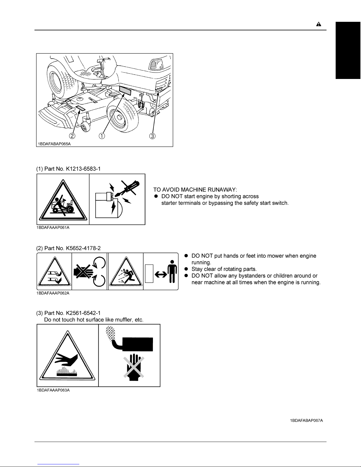
3. Do not start engine by shorting across starter
terminals or by bypassing the safety start switch. The
machine may start and move if normal starting circuitry
is bypassed.
4. Do not operate or idle engine in a poorly ventilated
area. Exhaust contains poisonous carbon monoxide, a
colorless and odorless gas.
C Working
1. Watch where you are going at all times. Watch for and
avoid obstacles. Be alert near trees and other
obstructions.
2. When working in groups, always let others know what
you are doing ahead of time.
3. Never try to get on or off a moving machine.
1. BEFORE OPERATING
2. OPERATING
Page 10
SAFE OPERATION-2
ENGLISH
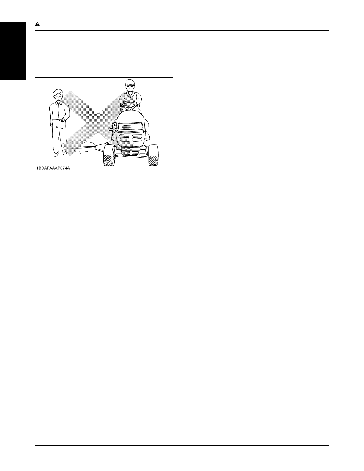
4. When using any attachments, never direct discharge
material toward bystanders. Do not allow anyone near
the attachments while in operation.
Do not mow when bystanders are present in the
mowing area.
5. To reduce fire hazards, keep the engine exhaust area
free of grass or leaves.
6. Slow down before turning.
7. Turn off blades when not mowing.
8. Mow only in daylight.
9. Be sure rotating blades and engine are stopped and
the key is removed before placing hands or feet near
blades and cleaning blockages or unclogging chute.
10.Shut the engine off and wait for all movement to stop
before removing grass catcher or unclogging chute.
11.Know what is behind you and disengage power to
mower before backing up. Do not mow while in reverse
unless absolutely necessary and only after
observation of the entire area behind the mower.
12.When mowing for the first time, cut the grass higher
than desired.
This will uncover any unseen object that may damage
the mower or grass catcher.
13.Always inspect the mower after striking any foreign
object. This will insure that all mower parts are safe
and secure and not damaged.
Repair or replace any damaged parts before restarting.
14.Use only implements recommended in this manual.
Use proper ballast to front or rear of machine to reduce
the risk of upsets. Follow the "SAFE OPERATION"
procedures specified in the manuals included with the
equipment.
15.Do not operate the mower without either the entire
grass catcher or the guard in place.
Be aware of the mower discharge direction and do not
point it at anyone.
16.Watch for traffic when operating near or crossing
roadways.
17.Stop the blades rotating before crossing surface other
than grass.
18.Never leave a running machine unattended. Always
turn off blades, set parking brake, stop engine, and
remove the key before dismounting.
19.Be extremely alert for all other traffic when operating
the mower and grass catcher near public roads or
highways.
20.Do not operate where machine could tip or slip. Do not
operate near ditches, holes, embankments, or other
terrain which may collapse under the machine's
weight. The risk of machine tip-over is increased when
the ground is loose or wet.
21.If the machine starts to vibrate abnormally, disengage
the drive to the attachments, stop the engine and
remove the key. Then check the machine immediately.
C Pulling loads
Use extra care when pulling loads to reduce the risk of
serious personal injury or death due to a machine tip-over.
a) Pull only from the hitch. Never attach loads to the axle
housing or any other point above hitch.
b) Limit loads to those you can safely control.
c) Do not turn sharply.
d) Use care when backing.
e) Use front ballast or wheel weights when suggested in
this Operator's Manual.
C Operation on slopes
Slopes are a major factor related to loss-of-control and tipover accidents, which can result in severe injury or death.
All slopes require extra caution. If you cannot back up the
slope or if you feel uneasy on it, do not mow it. The control
of a ride-on machine sliding on a slope will not be
regained by the application of the brake.
1. Mow up and down slopes, not across, to avoid
machine tip-over. Stay off hills and slopes too steep for
safe operation.
2. Remove obstacles such as rocks, tree limbs, etc.
3. Stay alert for holes in the terrain and other hidden
hazards. Keep away from drop-offs. Uneven terrain
could overturn the machine. Tall grass can hide
obstacles.
4. Use slow speed.
5. Follow KUBOTA's recommendations for wheel
weights or counterweights to improve stability.
6. The weight of grass in the grass catcher may increase
the possibility of tip over.
7. Keep all movement on slopes slow and gradual.
Do not make sudden changes in speed or direction.
8. Avoid starting or stopping on a slope. If tires lose
traction, disengage the blades and proceed slowly
straight down the slope.
9. If machine stops going uphill, disengage PTO and
back slowly down.
10.Reduce speed and exercise extreme caution on
slopes and in sharp turns to prevent tip-over or loss of
control.
DO
Page 11

-3SAFE OPERATION
ENGLISH
11.Use special caution when changing direction on
slopes.
1. Do not turn on slopes unless necessary and then turn
slowly and gradually downhill, if possible.
2. Do not use the machine on slopes of more than 11 .
3. Do not mow near drop-offs, ditches, or embankments.
The machine could suddenly turn over if a wheel falls
over the edge of a cliff or ditch, or if an edge caves in.
4. Do not mow on wet grass. Reduced traction could
cause sliding.
5. Do not try to stabilize the machine by putting your foot
on the ground.
6. Do not stop or start suddenly when going uphill or
downhill.
7. Never "freewheel". Do not let the machine travel
downhill with HST pedal at neutral position.
8. Do not modify or alter the machine.
C Children
Tragic accidents can occur if the operator is not alert to
the presence of children. Children are attracted to the
machine and the mowing activity. Never assume that
children will remain where you last saw them.
1. Keep children out of the mowing area and under the
watchful care of another responsible adult.
2. Be alert and turn machine off if children enter the area.
3. Before and when backing, look behind and down for
small children.
4. Never carry children. They may fall off and be
seriously injured or interfere with safe machine
operation.
5. Never allow children to operate the machine, even
under adult supervision. Local regulation can restrict
the age of the operator.
6. Use extra care when approaching blind corners,
shrubs, trees, or other obstructions that might hide
children from sight.
C Operators, age 60 years and above
Data indicates that operators, age 60 years and above,
are involved in a large percentage of machine-related
injuries. These operators should evaluate their ability to
operate the machine safety enough to protect themselves
and others from serious injury.
C Stopping
1. Make sure that the machine has come to a complete
stop before dismounting.
2. Before dismounting, disengage the PTO, lower all
implements, place all control levers in their neutral
positions, apply parking brake, turn off the engine and
remove the key.
3. Do not park the machine on a steep incline. Park on
relatively flat areas.
1. Before installing or using PTO-driven equipment, read
the manufacturer's manual and review the safety
labels attached to the equipment.
2. Wait until all moving components have completely
stopped before connecting, disconnecting, adjusting,
cleaning, or servicing any PTO-driven equipment.
3. Use the PTO with KUBOTA approved attachments.
1. Use lift link only with authorized attachments designed
for lift link usage.
1. Disengage power to attachment(s) when transporting
or not in use.
2. Do not tow this machine. Use a suitable truck or trailer
when transporting on public roads.
3. This machine is not allowed to be used on public
roads.
4. Use extra care when loading or unloading the machine
into a trailer or truck.
1. Before servicing the machine, park the machine on a
firm, level surface, set the parking brake, stop the
engine and remove the key.
2. Securely support machine or any machine elements
with stands or suitable blocking before working
underneath. For your safety do not rely or hydraulically
supported devices, they may leak down, suddenly
drop or be accidently lowered.
3. To avoid injury, do not adjust, unclog or service the
mower with the engine running. Make sure rotating
blades are stopped before dismounting the machine.
4. Disengage power to attachment(s), stop the engine
and remove the key before making any repairs or
adjustments.
5. Allow the machine to cool off before servicing the
engine, muffler, etc.
6. Keep your machine clean. Dirt and grass build-up can
cause fires and may lead to serious personal injury.
Replace all safety labels that are damaged, lost or
have otherwise become illegible. If a part to be
replaced has a safety label on it, obtain a new safety
label from your KUBOTA Dealer and install it in the
same place as on the removed part.
DO NOT
3. USING THE PTO
4. USING THE LIFT LINK
5. TRANSPORTING
6. SERVICING
Page 12
SAFE OPERATION-4
ENGLISH
7. Use extra care in handling diesel fuels. They are
flammable.
(1) Use only an approved container.
(2) Do not remove fuel cap or refuel with the engine
running. Allow engine to cool before refueling. Do
not smoke while refueling or when standing near
fuel.
(3) Do not refuel the machine indoors and always
clean up spilled fuel or oil.
(4) Do not store the machine or fuel container inside
where there is an open flame, such as in a water
heater.
(5) If the fuel tank has to be drained, this should be
done outdoors.
(6) Replace all fuel tanks and container caps
securely.
8. Do not change the engine governor setting or
overspeed the engine. Operating the engine at
excessive speed can increase the hazard of personal
injury.
9. Never run a machine inside a closed area.
10.Mower blades are sharp and can cut your hands. Wrap
the blade(s) or wear gloves, and use extra caution
when servicing them.
11.Keep nuts and bolts, especially blade attachment
bolts, tight and keep equipment in good condition. On
multi-bladed mowers, take care as rotating one blade
can cause other blades to rotate.
12.Do not smoke when working around the battery. Keep
all sparks and flames away from battery. The battery
presents an explosion hazard because it gives off
hydrogen and oxygen...especially when recharging.
13.Before "JUMP STARTING" a dead battery, read and
follow all of the instructions to help protect the
alternator from damage due to extreme load changes.
(See "JUMP STARTING" in "OPERATING THE
ENGINE" section.)
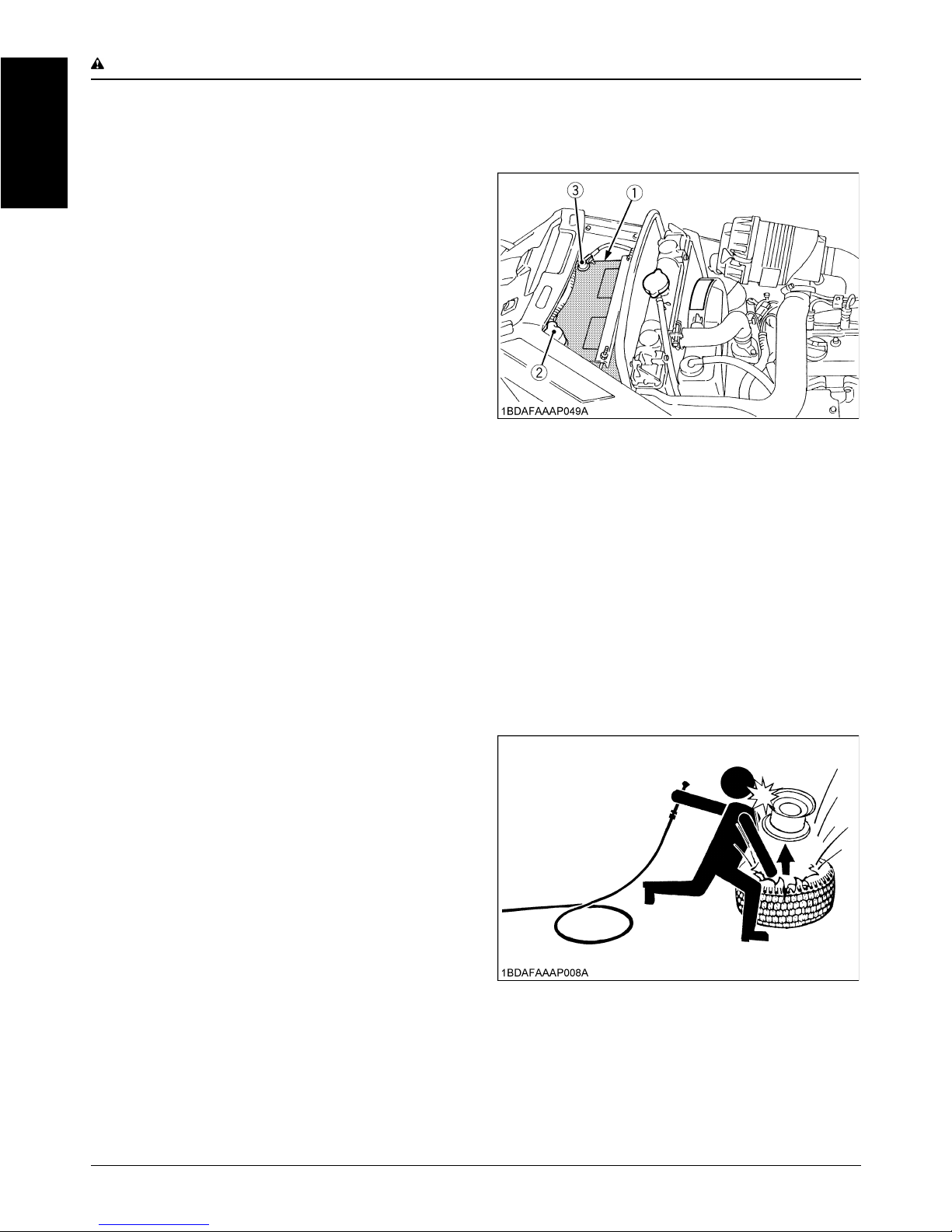
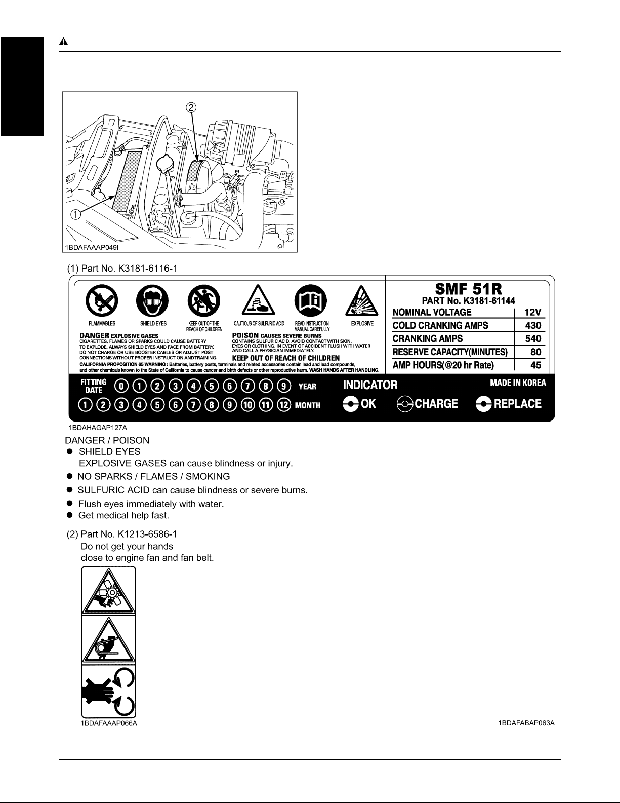
Batteries contain sulfuric acid and produce explosive
gases. Follow the instructions below to prevent
personal injury.
A Wear eye and skin protection.
A Keep sparks and flame away.
A Always have adequate ventilation while charging
or using the battery.
14.Keep first aid kit and fire extinguisher available at all
times.
15.Disconnect the battery's negative (-) cable before
working on or near electric components.
16.To avoid sparks from an accidental short circuit,
always disconnect the battery's negative (-) cable first
and connect it last.
17.Make sure circlips, nuts and spring lock washers are
properly secured on the front and rear wheels,
respectively.
18.Never tamper with safety devices.
Check their proper operation regularly.
19.Check brake operation frequently. Adjust and service
as required.
20.Properly dispose of used lubricants, filters, batteries,
and other such components.
21.Do not attempt to mount a tire on a rim. This should be
done by a qualified person with the proper equipment.
22.Always maintain the correct tire inflation pressure. Do
not inflate tires above the recommended pressure
shown in the Operator's Manual.
23.Securely support the machine when changing wheels.
24.Make sure that wheel bolts have been tightened to the
specified torque.
(1) Battery
(2) Positive cable (+)
(3) Negative cable (-)
Page 13
-5SAFE OPERATION
ENGLISH
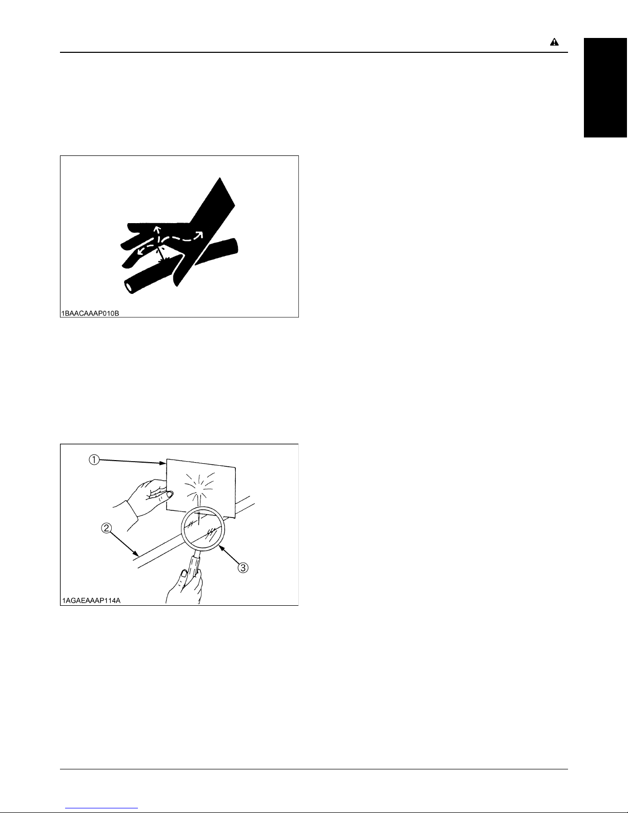
25.Escaping hydraulic fluid under pressure has sufficient
force to penetrate the skin causing serious personal
injury. Before disconnecting lines, be sure to relieve all
pressure. Before applying pressure to the system,
make sure all connections are tight and that lines,
pipes, and hoses are not damaged.
26.Fluid escaping from pinholes may be invisible. Use a
piece of cardboard or wood to search for suspected
leaks: do not use hands. Use safety goggles or other
eye protection.
If injured by escaping fluid, see a medical doctor at
once. Serious infection or reaction will result if proper
medical treatment is not administered immediately.
This fluid can produce gangrene or severe allergic
reaction.
27.Do not use beverage containers for waste fluids or
other products. Someone, particularly children, may
drink them by mistake.
28.Waste products such as used oil, fuel, hydraulic fluid,
and batteries, can harm the environment, people, pets
and wildlife. Please dispose properly.
29.See your local Recycling Center or KUBOTA Dealer to
learn how to recycle or get rid of waste products.
A A Material Safety Data Sheet (MSDS) provides
specific details on chemical products; physical and
health hazards, safety procedures, and emergency
response techniques. The seller of the chemical
products used with your machine is responsible for
providing the MSDS for that product upon request.
1. Keep the machine and supply of fuel in locked storage
and remove the key to prevent children or others from
playing or tampering with them.
2. When machine is to be stored for a long time,
disconnect battery cables or remove the battery.
Always remove the negative (-) cable first and reinstall
the negative (-) cable last.
3. Do not store the machine with fuel in the tank inside a
building where fumes may ignite. Allow the engine to
cool before storing.
4. To avoid the danger of exhaust fume poisoning, do not
operate the engine in a closed building without
adequate ventilation.
5. To reduce fire hazards, clean the machine thoroughly
before storage. Dry grass and leaves around the
engine and mufflers may ignite.
6. Moisture content in most grasses can damage the
mower if it is not properly cleaned after use. Always
make sure the mower is clean before storage.
(1) Cardboard
(2) Hydraulic line
(3) Magnifying glass
7. STORAGE
Page 14
SAFE OPERATION-6
ENGLISH
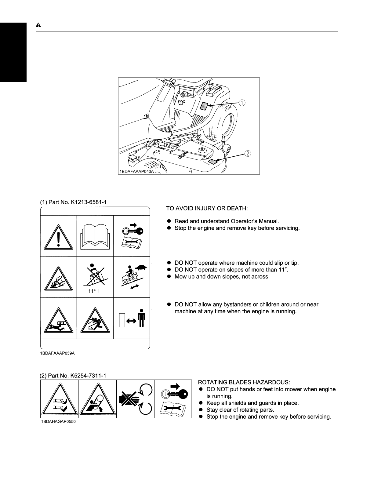
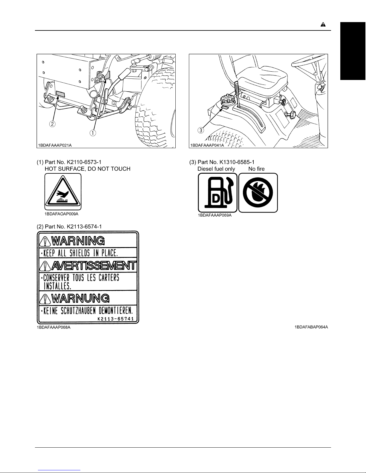
8. PICTORIAL SAFETY LABELS
Page 15
-7SAFE OPERATION
ENGLISH
Page 16
SAFE OPERATION-8
ENGLISH
Page 17
-9SAFE OPERATION
ENGLISH
1. Keep pictorial safety labels clean and free from obstructing material.
2. Clean pictorial safety labels with soap and water, dry with a soft cloth.
3. Replace damaged or missing pictorial safety labels with new labels from your local KUBOTA Dealer.
4. If a component with pictorial safety label(s) affixed is replaced with new part, make sure new label(s) is (are) attached
in the same location(s) as the replaced component.
5. Mount new pictorial safety labels by applying on a clean dry surface and pressing any bubbles to outside edge.
9. CARE OF PICTORIAL SAFETY LABELS
Page 18

Page 19
1SERVICING OF MACHINE
ENGLISH
SERVICING OF MACHINE
After reading this manual thoroughly, you will find that you
can do some of the regular maintenance yourself. Your
dealer is interested in helping you get the best
performance from your new machine and wants to help
you get the most value from it. When in need of parts or
major service, be sure to see your KUBOTA Dealer. When
in need of parts, be prepared to give your dealer the
machine, engine and mower serial numbers.
Locate the serial numbers now and record them in the
space provided.
C Warranty
This machine is warranted under the Kubota Limited
Express warranty a copy of which may be obtained from
your selling dealer. No warranty shall, however, apply if
the machine has not been handled according to the
instruction given in the Operator's Manual even it is within
the warranty period.
C Scrapping the machine and its procedure
To put the machine out of service, correctly follow the
local rules and regulations of the country or territory where
you scrap it. If you have questions, consult your local
KUBOTA Dealer.
Type Serial No.
Machine
Engine
Mower
Date of
Purchase
Name of Dealer
(To be filled in by purchaser)
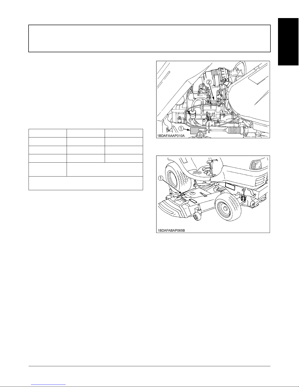
(1) Machine serial No.
(2) Engine serial No.
(1) Mower serial No.
Page 20

2 SPECIFICATIONS
ENGLISH
SPECIFICATIONS
Model G2160-2
Engine
Model D782
Type Water-cooled, Diesel engine
Total displacement cm 778
Gross power *1 kW (PS) 15.6 (20.7)
No.of cylinders 3
Starter Electric starter with battery
Battery 51R (12V, 430CCA)
Fuel
Diesel fuel No.1 [below -10 ]
Diesel fuel No.2 [above -10 ]
Preheating system Super glow
Engine stop Key stop
Capacities
Fuel tank L 22
Engine oil L 2.8
Radiator coolant L 2.1
Hydrostatic transmission oil L 4.5
Machine
PTO Shaft drive
PTO clutch Belt tension
PTO Brake Shoe
Tires
Front 16 x 6.50-8
Rear 23 x 10.50-12
Steering type Manual
Brake Internal expanding brake
Travel speed control Foot pedal
Transmission Hydrostatic
Traveling speeds
Forward km/h 0 to 15.0
Reverse km/h 0 to 6.0
Dimensions
Overall length mm 1885
Overall width (without mower) mm 1045
Overall height mm 1280
Wheel base mm 1290
Tread
Front mm 825
Rear mm 780
Weight (without mower) kg 390
Page 21
3SPECIFICATIONS
ENGLISH
NOTE:
*1: Manufacturer's estimate
(The company reserves the right to change the specifications without notice.)
IMPLEMENT LIMITATIONS
The KUBOTA Machine has been thoroughly tested for proper performance with implements sold or approved by KUBOTA.
Use of implements which exceed the maximum loading weight listed below, or which are not recommended for use with
the KUBOTA Machine may result in malfunctions or failures of the machine, damage to other property and injury to the
operator or others.
(Any malfunctions or failures of the machine resulting from use with improper implements are not covered by the warranty.)
Mower
Type RCK54-24G
Cutting width mm 1372
Cutting height mm 25 to102
Adjustment of cutting height Dial gauge
Mounting method Quick joint, Parallel linkage
Weight (Approx.) kg 95
Dimensions
Total length mm 946
Total width mm 1690
Total height mm 273
Discharge direction Right side
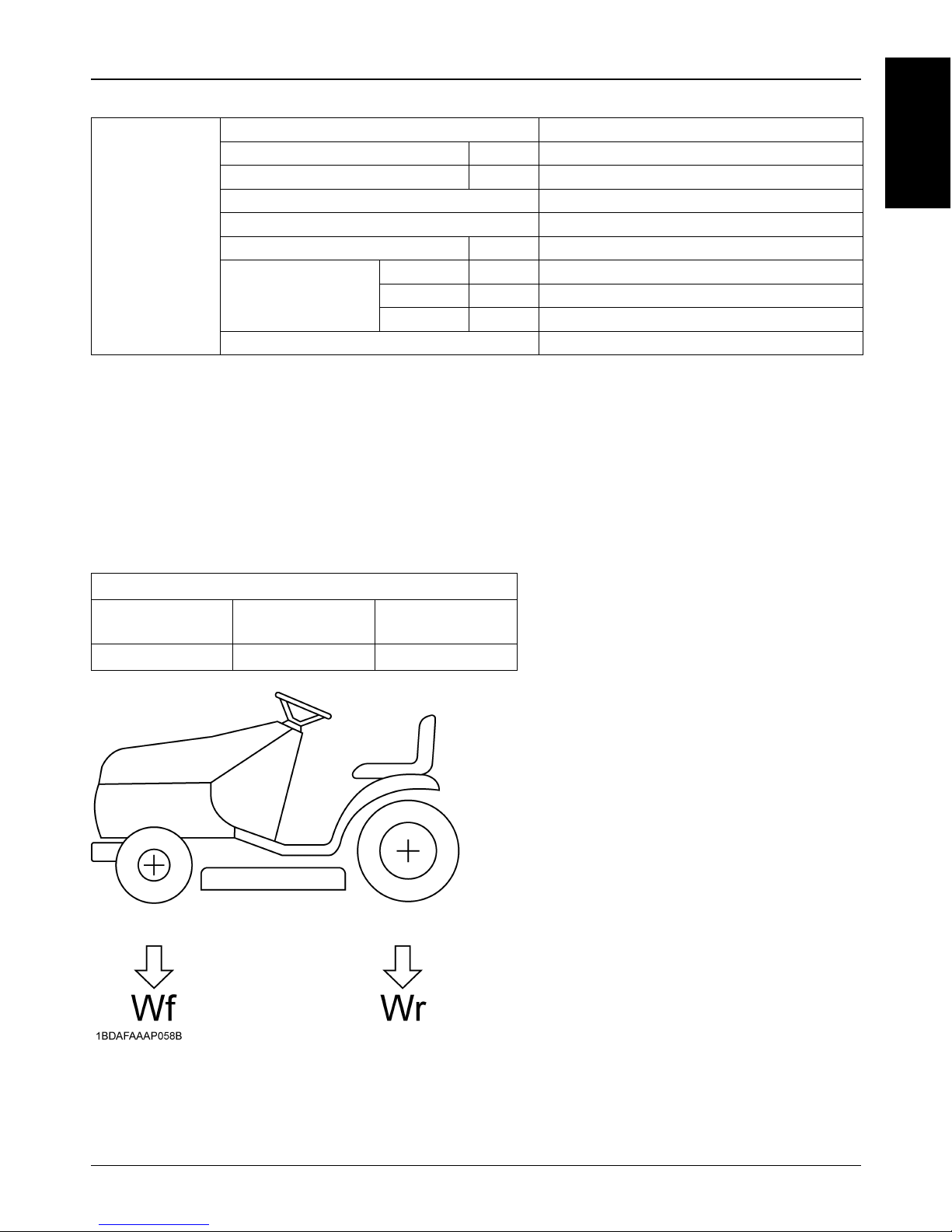
Maximum axle loading weight
Front axle
Wf
Rear axle
Wr
Total gross machine
weight
350 kg 550 kg 700 kg
Page 22

SPECIFICATIONS4
ENGLISH
BBallast
A Additional ballast will be needed for operating
heavy attachments. When the attachment is
raised, drive slowly over rough ground,
regardless of how much ballast is used.
A Add front ballast to increase front end stability
and help prevent possible front end tip up.
A Always back up when going up a slope. Driving
forward could cause the machine to tip-over
backward. Stay off hills and slopes too steep
for safe operation.
Front ballast is added for stability and steering control
when heavy rear mounted equipment such as the rotary
tiller is installed.
Front ballast also compensates for weight transferred to
the rear wheels by the draft of towed implements through
the hitch.
Add additional front ballast, if necessary, for stability and
safety during transport of heavy rear mounted equipment.
Front end ballast may not always maintain the required
stability if the machine is driven too fast over rough ground
with heavy rear mounted equipment in the raised position.
Use care and drive slowly under these conditions.
Limit ballast to machine operating capacity. Be sure to
remove ballast when it is not needed.
Add ballast to rear end if needed for stability. Heavy front
mounted attachments tend to lift rear wheels. Add enough
ballast to maintain steering control and prevent tip-over.
The Attachment's Manual shows how much rear ballast is
required for your application. Rear ballast is available
from your KUBOTA Dealer.
Page 23

5INSTRUMENT PANEL AND CONTROLS
ENGLISH
INSTRUMENT PANEL AND CONTROLS
(1) Easy checker
(2) Hour meter
(3) Throttle lever
(4) Key switch
(5) Hydraulic lift lever
(6) Light switch
(7) Parking brake pedal
(8) Brake pedal
(9) Speed control pedal
(10) PTO lever
Page 24

INSTRUMENT PANEL AND CONTROLS6
ENGLISH
B Throttle Lever
Pulling the throttle lever backward decreases the engine
speed and pushing it forward increases the engine speed.
B Key Switch
B Light Switch
Pushing the light switch forward illuminates the headlights
and pushing it backward turns the lights off.
B Speed Control Pedal
"FORWARD"
Depress the speed control pedal with the toe of your right
foot to move forward.
"REVERSE"
Depress the speed control pedal with the heel of your right
foot to move in reverse.
Depress the speed control pedal a little and you can drive
slowly.
To increase travel-speed, depress the speed control
pedal more until the desired speed is reached.
A When the parking brake is applied, the speed control
pedal is locked in the neutral position.
(1) Throttle lever (A) "FAST" :
(B) "SLOW " :
OFF......... The position where the key can be
inserted into or removed from the key
switch. [When the key is turned to this
position, the engine shuts off.]
ON........... The engine is running.
Preheat.... The super glow plug is heated.
Start......... Depress the brake pedal fully and pull the
PTO lever to the "DISENGAGED"
position, turn the key switch to this
position to start the engine.
(A) "OFF":
(B) "ON":
(C) "PREHEAT":
(D) "START":
(1) Light Switch (A) "ON": I
(B) "OFF":
(1) Speed control pedal (A) "FORWARD"
(B) "REVERSE"
Page 25

7INSTRUMENT PANEL AND CONTROLS
ENGLISH
B Brake Pedal
To apply the brakes, depress the brake pedal.
B Parking Brake Pedal
To apply the parking brake, depress the brake pedal and
the parking brake pedal simultaneously. Then release the
brake pedal while holding the parking brake pedal down.
To release the parking brake, depress the brake pedal
and release slowly.
A This machine is equipped with safety devices. If you
dismount from the seat and the parking brake is not
applied, the engine will stop automatically.
B Seat
To avoid personal injury:
A Make sure that the seat is completely secured
after each adjustment.
A Do not allow any person other than the
operator to ride on the machine.
C Position adjustment
The operator's seat position can be adjusted forward and
backward within a 102 mm range by pulling the seat
sliding lever.
C Suspension adjustment
Turn the suspension adjust knob to achieve the optimum
suspension setting.
(1) Brake pedal
(1) Brake pedal
(2) Parking brake pedal
(A) "PARKING"
(1) Seat sliding lever
(2) Suspension adjust knob
(1) Suspension adjust knob (A) To decrease tension
(B) To increase tension
Page 26

INSTRUMENT PANEL AND CONTROLS8
ENGLISH
B PTO lever
To engage mower blades, push the PTO lever to the
"ENGAGED" position. To stop the mower blades, pull the
PTO lever to the "DISENGAGED" position.
This machine is equipped with safety devices.
A If you dismount from the seat while the PTO is running,
the engine will stop automatically. (Operator presence
control)
A Before starting the engine, pull the PTO lever to the
disengaged position and depress brake pedal,
otherwise, the starter will not operate.
B Hydraulic lift lever
The hydraulic lift lever is used to raise and lower
implement used with the machine (ex.Mower).
To lower implement, push the lever FORWARD.
To raise it, pull the lever BACKWARD.
A Do not operate until the engine is warmed up. If
operation is attempted when the engine is still cold, the
hydraulic system may be damaged.
A Do not operate at slow Engine rpm. Move the throttle
lever above 1/2 throttle.
A If noises are heard when implement is lifting after the
hydraulic control lever has been activated, the
hydraulic mechanism is not adjusted properly. Contact
your KUBOTA Dealer for adjustment.
(1) PTO lever (A) "DISENGAGED":
(B) "ENGAGED":
(1) Hydraulic lift lever (A) "DOWN"
(B) "NEUTRAL"
(C) "UP"
Page 27

9INSTRUMENT PANEL AND CONTROLS
ENGLISH
B Cutting Height Control Dial
Raise the mower deck to the top position by pulling the
hydraulic lift lever backward. Turn the cutting height
control dial to the desired cutting height.
Lower the mower deck by pushing the hydraulic lift lever
forward.
Then the mower deck will be set to the cutting height.
B Hour meter
The hour meter starts to run when the key switch is turned
to the "ON" position.
B Easy Checker
B Overheat Alarm
If the temperature of the coolant rises to overheat
temperature, the overheat alarm whistles.
Check the machine by referring to "TROUBLE
SHOOTING" section.
(1) Cutting height control dial
(1) Hour meter
(A) If this warning light comes on during operation,
check the electrical charging system or consult
your KUBOTA Dealer.
(B) If this warning light comes on during operation,
check level of engine oil.
(C) If the fuel in the tank goes below the prescribed
level, the warning lamp in the Easy Checker will
come on.
If this should happen during operation, refuel as
soon as possible.
(D) If this warning light comes on during operation,
take the actions according to "Engine
Overheating Precautions".
(E) Glow plug Indicator (Pre-heating Indicator)
When the key switch is in the "Preheat" position,
the glow plug indicator illuminates.
Page 28

10 MOWER MOUNTING
ENGLISH
MOWER MOUNTING
ATTACHING THE MOWER
To avoid personal injury:
A Shut off the engine and remove the key before
attaching the mower.
BMounting the Mower Deck
1. Park the machine on level ground and place the
mower deck at the right side of the machine.
2. Set the anti-scalp rollers sideways. Turn the front
wheel to the left. Pull the hydraulic lift lever to raise
rear links.
3. Slide the mower deck under the machine, then return
wheels to straight ahead position.
4. Reset the front anti-scalp rollers to straight ahead
position (Refer to ADJUSTING CUTTING HEIGHT
section to set the anti-scalp rollers height.)
5. Place the hydraulic lift lever in the "DOWN" position.
Push down the rear links to align with the mower
bracket.
6. Release the L pins lock to attach the rear links to the
mower deck.
(A) "LEFT"
(B) "SLIDE"
(1) Hydraulic lift lever
(2) Mower's rear link
(1) Mower's rear link
(2) L pin
Page 29

11MOWER MOUNTING
ENGLISH
7. Attach the front links to the front roller brackets.
A Adjust the length (L) of the front link.
(See "Adjusting The Parallel Linkage" section)
8. Pull the lever fulcrum fixing pin and turn it counter
clockwise to unlock.
9. Hook and raise the front link with the link fixing lever,
then lay the link fixing lever onto the front bracket of
the machine.
10.Turn the lever fulcrum fixing pin clockwise and push it
into position to fix the link fixing lever.
11.Pull back the coupler of the universal joint.
Push the universal joint into the PTO shaft until the
coupler locks.
Slide the universal joint back and forth to make sure
the universal joint is locked securely.
A Finally pull the universal joint to check if it is tight in
position.
A For dismounting the mower deck, reverse the above
procedures.
(1) Front link
(2) Front roller bracket
(1) Link fixing lever
(2) Lever fulcrum fixing pin
(3) Front link
(4) Front bracket
(1) Universal joint
(2) Coupler
(A) "PULL"
Page 30

MOWER MOUNTING12
ENGLISH
[Model with the universal joint cover]
12.Extend the universal joint cover to the coupler of the
universal joint, and then set the projection of the
universal joint cover to the hole of the frame.
13.Attach the stay to the frame with the bolt.
A Make sure to install the stay to the frame with the bolt.
ADJUSTING THE PARALLEL LINKAGE
To avoid personal injury:
A Shut off the engine and remove the key.
A Set parking brake.
A Allow the blades to stop before making
adjustments.
A Blades may be sharp, when you handle blades,
wear heavy gloves or wrap end of blade with
rag.
1. Park the machine on a level surface.
2. Make sure the mower blades are level in the way
mentioned below. Then tighten the lock nuts securely.
Adjust (L) of front links with lock nut so that A is 0 to 5
mm. A=(Y)-(X)
(1) Universal joint cover
(2) Projection (Universal joint cover)
(3) Hole (Frame)
(1) Stay (Universal joint cover)
(2) Bolt
(1) Front link
(2) Blade (front)
(3) Blade (rear)
(F) Front
(R) Rear
Page 31

13MOWER MOUNTING
ENGLISH
ADJUSTING THE MOWER DECK (SIDE-TOSIDE)
To avoid personal injury:
A Shut off the engine and remove the key.
A Set parking brake.
A Allow the blades to stop before making
adjustments.
A Blades may be sharp. When you handle blades,
wear heavy gloves or wrap end of blade with a
rag.
1. Park the machine on a level surface.
2. Tire inflation pressure must be correct.
(See "TIRE" section.)
3. Raise the hydraulic lift lever to the top position. Turn
the cutting height control dial to adjust height to the
desired height.
4. Lower the mower deck by pushing the hydraulic lift
lever forward.
5. Turn the left blade so that it is parallel to rear axle. Hold
drive belt and turn the right blade so that it is parallel
to axle.
6. Measure from each outside blade tip (L) to (R) to the
level surface. The difference between measurements
should be less than 3 mm.
7. Remove the snap ring, plain washer and clevis pin.
Adjust the lift link length so that the difference between
measurements (L) and (R) is less than 3 mm.
8. Reinstall the snap ring, plain washer and clevis pin.
(A) "MEASURE THE HEIGHT"
(1) Lift link (Upper)
(2) Lift link (Lower)
(3) Snap ring
(4) Plain washer
(5) Clevis pin
Page 32

14 OPERATING THE ENGINE
ENGLISH
OPERATING THE ENGINE
To avoid personal injury:
A Read "Safe Operation" in the front of this
manual.
A Understand the pictorial safety labels located
on the machine.
A To avoid danger of exhaust fume poisoning, do
not operate the engine in a closed building
without proper ventilation.
A Never start engine while standing on ground.
Start engine only from operator's seat.
STARTING THE ENGINE
A If the hood is opened, the engine does not start.
A If the hood has been opened while the engine is
running, the engine stalls.
1. To set the parking brake, depress the brake pedal and
the parking brake pedal simultaneously.
2. To release the parking brake, depress the brake pedal
and release slowly.
1. Make sure that the hood is closed.
2. Set the parking brake.
(1) Brake pedal
(2) Parking brake pedal
Page 33

15OPERATING THE ENGINE
ENGLISH
3. Make sure that the PTO lever is in the
"DISENGAGED" position.
(1) PTO lever (A) "ENGAGED"
(B) "DISENGAGED"
4. Sit on the operator's seat and adjust the
seat position and suspension.
(1) Seat sliding lever
(2) Suspension adjust knob
5. Set the throttle lever 1/2 way forward.
(1) Throttle lever (A) "FAST" :
(B) "SLOW" :
6. Insert the key into the key switch and
turn the key switch to "PREHEAT"
position clockwise, and hold it for about
5 seconds.
Temperature Preheating Time
Over 0 5 sec.
Below 0 10sec.
(A) "OFF" :
(B) "ON" :
(C) "PREHEAT" :
(D) "START" :
Page 34

OPERATING THE ENGINE16
ENGLISH
A Do not turn the key switch to the "START" position
while the engine is running.
A When the temperature is below 0 , run the engine at
medium speed to warm up the lubricant of the engine
and transmission for at least 10 minutes. If the
machine is operated before the lubricant is warm
enough, the machine life will be shortened.
A Do not operate the machine under full load until it is
sufficiently warmed.
A Do not use starting fluid.
A When the ambient temperature is less than -15 ,
remove the battery from the machine and store it
somewhere warm until next operation.
CHECKING ENGINE START SYSTEM
The Engine Start System in your machine are designed to
protect you while operating. Please check these Engine
Start System periodically. It is recommended to check the
Engine Start System before daily operation.
To avoid personal injury:
A Do not allow anyone near the machine while
testing.
A If the machine does not pass one of the
following tests, do not operate the machine.
See your local KUBOTA Dealer.
A Sit on operator's seat for all tests.
A Check the following tests before operating the
machine.
1. Check the following tests before operating the mower.
Sit on the operator's seat for all tests.
2. If the machine does not pass one of the following tests,
do not operate the machine.
Contact your KUBOTA Dealer.
Test 1 (Safety Start Control 1)
1. Depress the brake pedal fully.
2. Engage the PTO lever.
3. Turn the key switch to the "START" position.
4. The engine should not crank.
Test 2 (Safety Start Control 2)
1. Disengage the PTO lever.
2. Release the brake pedal.
3. Turn the key to the "START" position.
4. The engine should not crank.
Test 3 (Engine Safety Control)
1. Open the hood.
2. Sit on the operator's seat.
3. Depress the brake pedal fully.
4. Turn the key to the "START" position.
5. The engine should not crank.
CHECKING OPC SYSTEM
The OPC (Operator Presence Control) system in your
machine are designed to protect you while operating.
Please check these OPC system periodically. It is
recommended to check the OPC system before dairy
operation.
To avoid personal injury:
A Do not allow anyone near the machine while
testing.
A If the machine does not pass one of the
following tests, do not operate the machine.
See your local KUBOTA Dealer.
A Check the following tests before operating the
machine.
1. Check the following tests before operating the mower.
Sit on the operator's seat for all tests.
2. If the machine does not pass one of the following tests,
do not operate the machine.
Contact your KUBOTA Dealer.
7. Turn the key switch to the "START"
position and release the key to the
"ON" position when the engine starts.
(1) Brake pedal
(2) PTO lever
(3) Key switch
(4) Throttle lever
(5) Hydraulic lift lever
(6) Parking brake pedal
Page 35

17OPERATING THE ENGINE
ENGLISH
Test 1 (Seat Safety Control 1)
1. Run the engine at half throttle.
2. Engage the PTO lever.
3. Stand up. (DO NOT GET OFF THE MACHINE.)
4. Engine should shut off.
Test 2 (Seat Safety Control 2)
1. Run the engine at half throttle.
2. Disengage the PTO lever.
3. Release the brake pedal.
4. Stand up. (DO NOT GET OFF THE MACHINE.)
5. Engine should shut off.
CHECK WHILE OPERATING THE ENGINE
- Check color of the exhaust fumes.
- Check the headlights.
- Check performance of the PTO clutch.
- Check Safety Switch, Seat Safety Control, and PTO
Safety Control.
If one of these do not operate properly, contact your
KUBOTA Dealer immediately.
- Check for abnormal noise and vibration.
- Check Easy Checker .
STOPPING THE ENGINE
WARMING UP
To avoid personal injury:
A Be sure to set the parking brake during warm-
up.
For 5 minutes after engine start-up, allow engine to warm
up without applying any load, this is to allow oil to reach
every engine part. If load should be applied to the engine
without this warm-up period, trouble such as seizure,
breakage or premature wear may develop.
BWarm-up and Transmission Oil in the Low
Temperature Range
Hydraulic oil serves as transmission fluid. In cold weather,
the oil may be cold with increased viscosity. This can
cause delayed oil circulation or abnormally low hydraulic
pressure for some time after engine start-up. This in turn
can result in trouble in the hydraulic system.
To prevent the above, observe the following instructions:
Warm up the engine at about 50% of rated rpm according
to the table below:
A Do not operate the machine under full load condition
until it is sufficiently warmed up.
(1) Brake pedal
(2) PTO lever
(3) Key switch
(4) Throttle lever
(5) Hydraulic lift lever
(6) Parking brake pedal
1. After slowing the engine to idle, turn
the key switch to the "OFF" position.
2. Remove the key.
3. Do not leave the key switch "ON" (key in
the "ON" position) as the battery will
discharge when the engine is not
running.
4. Set the parking brake.
Ambient temperature Warm-up time requirement
Higher than 0 Approx.5 minutes
-10 to 0 5 to 10 minutes
-20 to - 10 10 to 15 minutes
Below - 20 More than 15 minutes
Page 36

OPERATING THE ENGINE18
ENGLISH
JUMP STARTING
To avoid personal injury:
A Battery gases can explode. Keep cigarettes,
sparks, and flames away from battery.
A If machine battery is frozen, do not jump start
engine.
A Do not connect other end of negative (-) jumper
cable to negative (-) terminal of machine
battery.
When jump starting the engine, follow the instructions
below to safely start the engine.
1. Bring helper vehicle with a battery of the same voltage
as the disabled machine within easy cable reach.
"THE VEHICLES MUST NOT TOUCH".
2. Apply the parking brakes of both vehicles and put the
shift levers in neutral. Shut the engine off.
3. Put on safety goggles and rubber gloves.
4. Ensure the vent caps are securely in place.
(if equipped)
5. Attach the red clamp to the positive (red, (+) or pos.)
terminal of the dead battery and clamp the other end
of the same cable to the positive (red, (+) or pos.)
terminal of the helper battery.
6. Clamp the other cable to the negative (black, (-) or
neg.) terminal of the helper battery.
7. Clamp the other end to the engine block or frame of
the disabled machine as far from the dead battery as
possible.
8. Start the helper vehicle and let its engine run for a few
moments. Start the disabled machine.
9. Disconnect the jumper cables in the exact reverse
order of attachment. (Steps 7, 6 and 5).
A This machine has a 12 volt negative (-) ground starting
system.
A Use only same voltage for jump starting.
A Use of a higher voltage source on machine could
result in severe damage to machine electrical system.
Use only matching voltage source when "Jump
starting" a low or dead battery condition.
(1) Dead battery
(2) Jumper cables
(3) Engine block or frame
(4) Helper battery
Connect cables in numerical order.
Disconnect in reverse order after use.
Page 37

19DRIVING THE MACHINE
ENGLISH
DRIVING THE MACHINE
DRIVING
To move forward:
Depress the speed control pedal with the toe of your right
foot to move forward.
To move backwards:
Depress the speed control pedal with the heel of your right
foot to move in reverse.
A When the parking brake is applied, the speed control
pedal is locked in the neutral position.
STOPPING
PARKING
Before leaving the operator's position:
A Set parking brake.
A Lower all implements to the ground.
A Shut off the engine.
A Remove the key.
TO LOCK THE PARKING BRAKE
1. Depress the brake pedal and the parking brake pedal
simultaneously.
2. Release the brake pedal while holding the parking
brake pedal depressed.
TO UNLOCK THE PARKING BRAKE
1. Depress the brake pedal and release slowly.
If it is necessary to park on an incline, be sure to block the
wheels on the downhill side to prevent accidental rolling of
the machine.
TOWING
A Do not tow this machine. Use a suitable truck or trailer
when transporting on public roads.
1. Depress the brake pedal to release the
parking brake.
2. Depress the speed control pedal with
your right foot to move forward or
reverse.
(1) Speed control pedal (A) "FORWARD"
(B) "REVERSE"
1. Release the speed control pedal and
depress the brake pedal to stop the
machine.
2. Push the PTO lever to the "DISENGAGED"
position.
3. Slow the engine down.
(1) Blocks
Page 38

20 OPERATING THE MOWER
ENGLISH
OPERATING THE MOWER
To avoid serious injury or death:
A Do not operate mower without deflector shield.
To avoid personal injury:
A Clear the work area of objects which might be
picked up and thrown by blades.
A Do not direct the opening of the chute at
bystanders or animals. Ejected objects may
cause injury. Plan your mowing carefully
before starting operation.
A Keep bystanders and animals away from the
mowing area.
A Be sure to disengage the PTO and sit on the
operator's seat before starting the engine.
ADJUSTING CUTTING HEIGHT
To avoid serious injury or death:
A Never engage the PTO and blades in transport
position.
1. To set the cutting height, pull the hydraulic lift lever
backward to raise mower deck to the top position. Turn
the cutting height control dial to adjust height.
2. Set the anti-scalp rollers' height as shown to keep
clearance between rollers and ground more than 6
mm.
3. Lower the mower deck by pushing the hydraulic lift
lever downward. This lowers the mower deck from the
"Transport" position to the "Operating" position.
4. Use the higher settings for mowing in a rough area or
when mowing tall grass. Lower settings should be
used only for smooth lawns where short grass is
desired.
(1) Cutting height control dial
(2) Hydraulic lift lever
(1) Anti-scalp roller
Page 39

21OPERATING THE MOWER
ENGLISH
OPERATING THE MOWER
1. Start the engine.
2. Set the throttle lever to the "FAST" position.
3. Push down the PTO lever to the "ENGAGED" position.
A For best cut quality and performance, always mow
with the throttle lever in "FAST" position.
Use the speed control pedal to select the desired mowing
speed range.
(1) During heavy duty use, operate the machine at a
slower ground speed or go over the area twice.
The first pass should be with the deck at the
highest cutting position then mow to desired
height.
(2) The mower will not cut cleanly if the ground
speed is too high or if the blade speed drops due
to an overload.
4. Control ground speed by using the speed control
pedal of the machine.
A Keep the mower deck in the fully raised position when
the mower is not engaged.
(A) "FAST" position
(B) "SLOW" position
(1) PTO lever (A) "ENGAGED"
(B) "DISENGAGED"
Page 40

22 MAINTENANCE
ENGLISH
MAINTENANCE
SERVICE INTERVALS
Items
Every
50 Hr
Hour meter reading Refer-
ence
page
50 100 150 200 300 400 450 500 After
1 Tires Check Every 50 Hr 29
2 Battery condition Check Every 50 Hr 32
3 Engine oil Change Every 200 Hr 35
4 Engine oil filter cartridge Change Every 200 Hr 34
5 Transmission fluid Change Every 400 Hr 38
6 Transmission oil filter cartridge Replace Every 200 Hr 35
7 Transmission oil strainer Clean Every 400 Hr 38
8 Hydraulic hose
Check Every 200 Hr 37
Replace Every 2 Years* 41
9 Fuel lines
Check Every 100 Hr 36
Replace Every 2 Years* 41
10 Fuel filter
Check Every 100 Hr 36
Replace Every 500 Hr 39
11
Fuel injection nozzle injection
pressure
Check Every 1500 Hr 39
12 Injection pump Check Every 3000 Hr 39
13 Intake air line
Check Every 200 Hr 37
Replace Every 2 Years 41
14 Radiator hose and clamp
Check Every 200 Hr 37
Replace Every 2 Years* 41
15 Radiator core Clean Every 100 Hr** 36
16 Cooling system Clean Every 1 Year 40
17 Coolant Change Every 1 Year 39
18 Air cleaner element
Clean ** 33
Replace Every 1 Year** 39
19 Fan belt tension Adjust 30
20 Front PTO belt tension Adjust *** 34
21 Brake play Adjust 30
22 Greasing --- 31
23 Mower gear box oil Change Every 150 Hr ---
24
Mower gear box oil seal
Replace Every 2 Years* ---
Page 41

23MAINTENANCE
ENGLISH
LUBRICANTS
To prevent serious damage to hydraulic systems, use only KUBOTA genuine fluid or its equivalent.
Note *1 Oil amount when the oil level is at the upper level of the oil level gauge.
*2 KUBOTA original transmission hydraulic fluid
IMPORTANT:
The maintenance indicated by must be done initially.
* Replace only if necessary.
** This maintenance should be done more often in dusty conditions than in normal conditions.
*** Initial elongation of the front PTO belt may occur prior to 25 hours. Adjust the tension spring length as needed to
maintain belt tension.
These items should be serviced by an authorized KUBOTA Dealer, unless the owner has the proper tools and is
mechanically proficient.
Consult your local KUBOTA Dealer for this service.
Place Capacity Lubricants
Engine crankcase 2.8 L *1
A Engine oil: API Service classification CF (or better)
Above 25 : SAE 30, SAE 10W-30 or SAE 15W-40
0 to 25 : SAE 20, SAE 10W-30 or SAE 15W-40
Below 0 : SAE 10W, SAE 10W-30 or SAE 15W-40
Transmission
(Including HST & CYLINDER)
4.5 L
A KUBOTA UDT or SUPER UDT fluid *2
Mower gear box 0.4 L A SAE #90 gear oil
King pin
Center pin
Universal joint
Spindle shaft
Belt tension pulley
Belt tension pivot
Balance shaft
Tension lever
Until grease over flows
A Multipurpose EP2 Grease
(NLGI Grade No.2)
Link fulcrum
PTO lever (fulcrum)
Front PTO cable
Brake pedal shaft
Speed control pedal shaft
Throttle cable
Mower universal joint
Front link
Mower link
Moderate Amount
A Oil or Spray type grease
Fuel tank 22 L
A No.2-D diesel fuel
A No.1-D diesel fuel if temperature is below -10
Radiator 2.1 L A Fresh clean water with anti-freeze
Radiator recovery tank 0.25 L
Page 42

24 MAINTENANCE
ENGLISH
A To prevent serious damage to hydraulic systems, use only KUBOTA genuine fluid or its equivalent.
C Engine Oil:
A Oil used in the engine should have an American Petroleum Institute (API) service classification and Proper SAE
Engine Oil according to the ambient temperatures as shown above:
A With the emission control now in effect, the CF-4 and CG-4 lubricating oils have been developed for use of a low-
sulfur fuel on on-road vehicle engines. When an off-road vehicle engine runs on a high-sulfur fuel, it is advisable to
employ the "CF or better" lubricating oil with a high Total Base Number (TBN of 10 minimum).
C Fuel:
A Cetane number of 45 minimum. Cetane number greater than 50 is preferred, especially for temperatures below
-20 or elevations above 1500 m.
A If diesel fuel with sulfur content greater than 0.5% (5000 ppm) sulfur content is used, reduce the service interval for
engine oil and filter by 50%.
A NEVER use diesel fuel with sulfur content greater than 0.05% (500 ppm) for EXTERNAL EGR type engine.
A DO NOT use diesel fuel with sulfur content greater than 1.0% (10000 ppm).
A Diesel fuels specified to EN 590 or ASTM D975 are recommended.
A No.2-D is a distillate fuel of lower volatility for engines in industrial and heavy mobile service. (SAE J313 JUN87)
C Transmission Oil:
The oil used to lubricate the transmission is also used as hydraulic fluid. To insure proper operation of the hydraulic
system and to complete lubrication of the transmission, it is important that a multi-grade transmission fluid is used in
this system. We recommend the use of KUBOTA UDT or SUPER UDT fluid for optimum protection and performance.
(Consult your local KUBOTA Dealer for further detail.)
Do not mix different brands together.
A Indicated capacities of water and oil are manufacturer's estimate.
A Refer to the following table for the suitable API classification engine oil according to the engine type (with internal
EGR, external EGR or non-EGR) and the fuel (low-sulfur or high-sulfur fuel).
Fuel used
Engine oil classification (API classification)
Oil class of engines except external EGR Oil class of engines with external EGR
High Sulfur Fuel
[ 0.05% (500 ppm)]
CF
(If the "CF-4, CG-4, CH-4 or CI-4" lubricating oil is
used with a high-sulfur fuel, change the lubricating
oil at shorter intervals. (approximately half))
---
Low Sulfur Fuel
[<0.05% (500 ppm)] or
Ultra Low Sulfur Fuel
[<0.0015% (15 ppm)]
CF, CF-4, CG-4, CH-4 or CI-4
CF or CI-4
(Class CF-4, CG-4 and CH-4 engine oils
cannot be used on EGR type engines)
EGR: Exhaust Gas Re-circulation
A The CJ-4 engine oil is intended for DPF (Diesel Particulate Filter) type engines, and cannot be used on this
machine.
except external EGR with external EGR
Models G2160-2 ---
Page 43

25PERIODIC SERVICE
ENGLISH
PERIODIC SERVICE
HOW TO OPEN THE HOOD
To avoid personal injury:
A Never open the hood while the engine is
running.
A Do not touch muffler or exhaust pipes while
they are hot;
Severe burns could result.
To open the hood, lift the hood as shown in the figure
below.
DAILY CHECK
To prevent trouble from occurring, it is important to know
the conditions of the machine. Check it before starting.
To avoid personal injury:
A Be sure to check and service the machine on a
level surface with the engine shut off, the key
removed and the parking brake "ENGAGED".
No. Check item
Reference
Page
Walking
around the
machine
1 Oil and water leak ---
2 Engine oil level 26
3Fuel level 26
4 Coolant level in the recovery tank 39
5
Damage of machine body,
tightness of all bolts and nuts
---
6 Radiator screen 27
7 Panel screen 27
8 Check air cleaner ---
9 Oiling 27
Mower 1 Make sure blade bolts are tight. 43
2 Check blades for wear or damage. 43
3 Check all hardware. ---
4 Make sure all pins are in place. ---
Others
1
Check the areas where previous
trouble was experienced.
---
While sitting in
the Operator's
Seat
1 Speed control pedal, Brake pedal ---
2
Parking brake
---
Turning the
key switch on
1
Headlights
---
Starting the
engine
1 Color of the exhaust fumes ---
2
Safety start switch and seat safety
control if either of these do not
operate properly, contact your
KUBOTA Dealer immediately.
16
3
Check for abnormal noise and
vibration
---
4 Check Easy Checker 5
Page 44

PERIODIC SERVICE26
ENGLISH
BChecking Engine Oil Level
To avoid personal injury:
A Always stop the engine and remove the key
before checking oil.
C Oil level check
1. Check engine oil before starting and 5 minutes or more
after the engine has stopped.
2. Wipe dipstick area clean.
3. To check the oil level, remove the dipstick, wipe it
clean, replace it, and draw it out again. Check to see
that the oil level is between the 2 notches.
4. Add new oil to the prescribed level at the oil port if
necessary.
5. When using a different brand or viscosity oil from the
previous one, remove all of the old oil. Never mix 2
different types of oil.
6. Use the proper Engine Oil SAE according to the
ambient temperatures. (See "LUBRICANTS".)
BChecking Amount of Fuel and Refueling
To avoid personal injury:
A Handle fuel carefully. If the engine is running,
do not fill the fuel tank. If engine is hot, let
engine cool several minutes before adding fuel.
Do not smoke while filling the fuel tank or
servicing the fuel system. Fill fuel tank only to
bottom of filler neck.
Check the fuel level. Take care that the fuel tank does not
become empty.
A Use Diesel Fuel Only.
1. Use No.2 diesel fuel.
2. Use No.1 diesel fuel if the temperature is below -10 .
3. Always use a strainer when refueling to prevent fuel
injection pump contamination.
(1) Engine oil port
(1) Oil level dipstick (A) "UPPER LEVEL"
(B) "LOWER LEVEL"
Fuel tank capacity 22L
Page 45

27PERIODIC SERVICE
ENGLISH
BChecking and Cleaning Radiator to
Prevent Overheating
To avoid personal injury:
A Be sure to stop the engine and remove the key
before cleaning.
Daily or after every 5 hours of operation, check to be sure
the radiator screen and panel screen are clean. Dirt or
chaff on the radiator screen or radiator core decreases
cooling performance.
1. Remove the radiator screen and remove all foreign
material.
2. Remove the dust from between the fins and the tube.
3. If scale forms in the tube, clean with scale inhibitor or
its equivalent.
4. Each time the panel screen is covered with grass
during operation, wipe off the screen by hand.
Check the radiator screen from time to time if grass
often gets on it.
5. If dust or chaff is accumulated inside of the panel,
clean the inside of the panel.
BOiling
To avoid personal injury:
A Be sure to stop the engine and remove the key
before oiling.
Oil the following points before starting.
(1) Panel screen
(2) Radiator screen
(1) Link fulcrum
(1) PTO lever (fulcrum)
(1) Front PTO cable
Page 46

PERIODIC SERVICE28
ENGLISH
(1) Brake pedal
(1) Seat adjuster
(1) Speed control pedal shaft
(1) Throttle cable
(1) Mower universal joint
(1) Front link
Page 47

29PERIODIC SERVICE
ENGLISH
A Oil these points on both sides of the machine.
EVERY 50 HOURS
BChecking Tire Pressure
To avoid personal injury:
A Do not attempt to mount a tire on a rim. This
should be done by a qualified person with the
proper equipment.
A Always maintain the correct tire pressure.
Do not inflate tires above the recommended
pressure shown in the Operator's Manual.
A Do not use tires larger than specified.
BInflation Pressure
Though the inflation pressure is factory-set to the
prescribed level, it naturally drops slowly in the course of
time. Thus, check it and inflate as necessary.
A When jacking up the rear tires, be sure
(1) To block the front tires.
(2) To position a jack inside beside either of the
supporting plates.
(1) Around the hole of the mower link
(2) Around the pin
(3) Pivot of mower link
(4) Pivot of lift arm
Tire Sizes Inflation Pressure
Front 16x6.50-8Turf 190kPa (1.9kgf/cm )
Rear 23x10.50-12Turf 140kPa (1.4kgf/cm )
(1) Ground (A) "INSUFFICIENT"
(B) "NORMAL"
(C) "EXCESSIVE"
Page 48

PERIODIC SERVICE30
ENGLISH
BChecking Brake Pedal
To avoid personal injury:
A When making adjustments, park the machine
on a flat area, block wheels, stop engine and
remove the key.
Correct play ranges from 15 to 25 mm. If it is not correct,
loosen the lock nut (2) and turn the nut (3) in the desired
direction until the proper play is achieved. After
adjustment, retighten lock nut securely.
BChecking Fan Drive Belt Tension
To avoid personal injury:
A Be sure to stop the engine and remove the key
before checking belt tension.
If the fan drive belt becomes loose, the engine may
overheat. To adjust, loosen bolts and turn the alternator to
tighten the belt. After adjustment, securely tighten the
bolts.
Moderate belt tension:
The belt should deflect approx. 10 mm when the center of
the belt is depressed with finger pressure of 98N (10kgf).
A When replacing fan drive belt, be careful not to catch
it on the cap under the water pump. See the illustration
to the left.
(1) Brake pedal
(2) Lock nut
(3) Nut
(4) Spring
(A) Play 15 to 25 mm
(1) Cap
(2) Tension bolt
(3) Alternator
(4) Adjusting bolt
(A) 10 mm
Page 49

31PERIODIC SERVICE
ENGLISH
BLubricating All Grease Fittings
To avoid personal injury:
A Be sure to stop the engine and remove the key
before greasing.
Grease the following grease fittings.
(1) King pin
(2) Center pin
(1) Mower universal joint
(1) Machine universal joint
(1) Grease fitting (Spindle shaft)
(2) Grease fitting (Belt tension pulley)
(3) Grease fitting (Belt tension pivot)
(1) Tension lever
Page 50

PERIODIC SERVICE32
ENGLISH
BBattery Condition
To avoid the possibility of battery explosion:
For the refillable type battery, follow the
instructions below.
A Do not use or charge the refillable type battery
if the fluid level is below the LOWER (lower limit
level) mark. Otherwise, the battery component
parts may prematurely deteriorate, which may
shorten the battery's service life or cause an
explosion. Check the fluid level regularly and
add distilled water as required so that the fluid
level is between the UPPER and LOWER levels.
To avoid serious injury or death:
A When the battery is being activated, hydrogen
and oxygen gases in the battery are extremely
explosive. Keep open sparks and flames away
from the battery at all times, especially when
charging the battery.
To avoid serious injury:
A Batteries, battery posts, terminals and related
accessories contain lead and lead compounds,
and other chemicals known to the State of
California to cause cancer and birth defects or
other reproductive harm. WASH HANDS
AFTER HANDLING.
A Never remove the battery cap while the engine
is running.
A Keep electrolyte away from eyes, hands and
clothes. If you are spattered with it, wash it
away completely with water immediately and
get medical attention.
A Keep open sparks and flames away from the
battery at all times. Hydrogen gas mixed with
oxygen becomes very explosive.
A Wear eye protection and rubber gloves when
working around battery.
A Mishandling the battery shortens the service life and
adds to maintenance costs.
The original battery is maintenance free, but needs
some servicing.
If the battery is weak, the engine will be difficult to start
and the lights will be dim. It is important to check the
battery periodically.
A When exchanging an old battery for new one, use
battery of equal specification in table below.
(For non-accessible maintenance-free type batteries.)
Maintenance-free, non-accessible batteries are designed
to eliminate the need to add water. Yet the volume of
electrolyte above plates may eventually become depleted
due to abnormal conditions such as high heat or improper
regulator setting. Use a voltmeter to check the state of
charge. (See reference chart below to determine if
charging is necessary.)
C Battery Charging
To avoid serious injury or death:
A When the battery is being activated, hydrogen
and oxygen gases in the battery are extremely
explosive. Keep open sparks and flames away
from the battery at all times, especially when
charging the battery.
To avoid serious injury:
A When disconnecting the cable from the battery,
start with the negative terminal first. When
connecting the cable to the battery, start with
the positive terminal first.
A Never check battery charge by placing a metal
object across the posts.
Use a voltmeter or hydrometer.
The factory-installed battery is of non-refillable type.
If the battery is weak, charge the battery or replace it
with new one.
Battery
Type
Volts
(V)
Reserve
Capacity
(min)
Cold
Cranking
Amps
Normal
Charging
Rate(A)
51R 12 80 430 4.5
Battery voltage Reference state of charge
12.6 100%(Full charge)
12.4 75%
12.2 50%
12.0 25%
11.8 0%
Page 51

33PERIODIC SERVICE
ENGLISH
1. To slow charge the battery, connect the battery
positive terminal to the charger positive terminal and
the negative to the negative, then charge for at least 1
hour at 4.5 amperes.
2. A boost charge is only for emergencies. It will partially
charge the battery at a high rate and in a short time.
When using a boost-charged battery, it is necessary to
recharge the battery as early as possible.
Failure to do this will shorten the battery's service life.
3. When the specific gravity of electrolyte is between
1.27 and 1.29 the charging is completed.
C Battery for storage
1. When storing the machine for a long period, remove
the battery from machine, adjust the electrolyte to the
proper level and store in a dry place out of direct
sunlight.
2. The battery self-discharges while it is stored.
Recharge it once every 3 months in hot seasons and
once every 6 months in cold seasons.
BCleaning Air Cleaner Element
1. The air cleaner uses a dry element, never apply oil.
2. Do not touch the filter element except where cleaning
is required. To clean the element, use clean and dry
compressed air on the inside of the element. Air
pressure should not exceed 205 kPa (2.1kgf/cm ).
A Operating in dusty conditions requires frequent
maintenance.
(1) Battery
(2) Ground cable
(+): Positive terminal
(-): Negative terminal
(1) Air cleaner cover
(2) Air cleaner element
Page 52

PERIODIC SERVICE34
ENGLISH
BChecking Front PTO Belt Tension
A Always stop the engine, set the parking brake,
remove the key, and disengage the PTO lever
before working on the front PTO.
C Adjusting
If the front PTO belts slip when the PTO is operating under
load, check the front PTO belt tension and adjust the
tension spring length, as explained below.
1. Engage the PTO lever.
2. Measure tension spring length (L).
3. If (L) is shorter than 87 mm adjust it with the tension
clutch cable adjusting nut.
A (L) should be 88 to 90 mm
4. After adjustment tighten the nut securely.
A When replacing the new front PTO belts, (L) should
be 91 to 92 mm
A When replacing the front PTO belts, be sure to replace
the complete set. These belts are a matched set.
EVERY 200 HOURS AFTER 50 HOURS
BEngine Oil Filter Cartridge Change
To avoid personal injury:
A Be sure to stop the engine and remove the key
before changing the oil and the oil filter
cartridge.
A Allow engine to cool down sufficiently; oil can
be hot and may cause burns.
1. The oil filter cartridge must be changed every 200
service hours.
2. Apply a slight coat of oil onto the rubber gasket of new
cartridge.
3. To install the new cartridge, screw it in by hand. Over
tightening may cause deformation of the rubber
gasket.
4. After the new cartridge has been replaced, the engine
oil level normally lowers a little. Add engine oil to
proper level. Check for oil leaks around filter gasket.
A To prevent serious damage to the engine,
replacement element of the recommended type must
be used. Use only a genuine KUBOTA filter or its
equivalent.
(1) Adjust nut
(1) Engine oil filter cartridge
Page 53

35PERIODIC SERVICE
ENGLISH
BChanging Engine Oil
To avoid personal injury:
A Be sure to stop the engine and remove the key
before changing the oil.
A Allow engine to cool down sufficiently; oil can
be hot and may cause burns.
1. To change the used oil, remove the drain plug at the
bottom of the engine and drain the oil completely. The
used oil can be drained out more easily if the engine is
warm.
2. Fill with the new oil up to the upper notch on the
dipstick.
3. To check the oil level. Remove the dipstick, wipe it
clean, insert it and draw it out again. Check to see the
oil level is between the 2 marks.
BTransmission Oil Filter Cartridge Change
To avoid personal injury:
A Be sure to stop the engine and remove the key
before changing the oil filter cartridge.
A Allow transmission case to cool down
sufficiently; oil can be hot and may cause
burns.
1. The oil filter cartridge must be changed every 200
service hours.
2. Remove the oil filter cartridge by using the filter
wrench.
3. Lightly tighten the screw (A) by using a screwdriver.
4. Apply a slight coat of oil onto the cartridge gasket.
5. To install the new cartridge, screw it in by hand. Over
tightening may cause deformation of rubber gasket.
6. After the new cartridge has been replaced, the
transmission fluid level normally lowers a little. Add
fluid to proper level. Check for oil leaks around filter
gasket.
(1) Drain plug
(1) Oil filter cartridge
Page 54

PERIODIC SERVICE36
ENGLISH
A To prevent serious damage to a hydraulic system, the
replacement filter must be a highly efficient, 10 m
filter. Use only a genuine KUBOTA filter or its
equivalent.
EVERY 100 HOURS
BChecking Fuel Lines and Fuel Filter
To avoid personal injury:
A Be sure to stop the engine and remove the key
when attempting to make the following checks
and changes.
A Never fail to check the fuel lines periodically.
The fuel lines are subject to wear and aging.
Fuel may leak out onto the running engine,
causing a fire.
The fuel line connections should be checked annually or
every 100 service hours, whichever comes first.
1. The fuel line is made of rubber and ages regardless of
service period.
2. If the fuel line and clamps are found damaged or
deteriorated, replace them.
3. Check fuel filter, if it is clogged by debris, replace it.
A When the fuel line is disconnected for maintenance or
repair, close both ends of the fuel line with a piece of
clean cloth or paper to prevent dust and dirt from
entering. In addition, particular care must be taken not
to admit dust and dirt into the fuel pump. Entrance of
dust and dirt causes malfunction of the fuel pump.
BCleaning Radiator Core
1. The radiator core should be cleaned on the following
occasions:
(A) Every 100 Hr or 1 year service, whichever comes
first.
(B) When adding anti-freeze solution.
2. When cleaning the radiator core, the KUBOTA Scale
inhibitor No.20 or its equivalent, is recommended to
effectively wash away the scale build-up.
(1) Pipe clamps (2) Fuel line (3) Fuel filter
Page 55

37PERIODIC SERVICE
ENGLISH
EVERY 200 HOURS
BChecking Radiator Hose and Clamp
Check to see if radiator hoses are properly fixed every 200
hours of operation or 6 months, whichever comes first.
1. If clamp bands are loose or water leaks, tighten bands
securely.
2. Replace hoses and tighten clamp bands securely, if
radiator hoses are swollen, hardened or cracked.
BChecking Hydraulic Hose
To avoid personal injury:
A Be sure to stop the engine and remove the key
before checking and replacing hydraulic hose.
A Allow transmission case to cool down
sufficiently; oil can be hot and may cause
burns.
Check to see if hydraulic hoses are properly fixed every
200 hours of operation.
1. Check to see that all lines and hose clamps are tight
and not damaged.
2. If hoses and clamps are found worn or damaged,
replace or repair them at once.
BChecking Intake Air Line
1. Check to see that hoses and hose clamps are tight and
not damaged.
2. If hoses and clamps are found worn or damaged,
replace or repair them at once.
(1) Radiator core
(2) Radiator hose
(1) Mower lift cylinder hose
(1) Hose
(2) Clamp
Page 56

PERIODIC SERVICE38
ENGLISH
EVERY 400 HOURS
BChanging Transmission Fluid
To avoid personal injury:
A Be sure to stop the engine and remove the key
before changing or checking the oil.
A Allow transmission case to cool down
sufficiently; oil can be hot and may cause
burns.
Draw out the dipstick, wipe it clean, replace it, and draw it
out again. Check to see that the fluid level is on the upper
notch. If low, replenish through the fluid port. Use UDT or
SUPER UDT hydrostatic transmission fluid or its
equivalent. (See "LUBRICANTS" in Maintenance Section)
The fluid in the transmission case is also used for the
hydrostatic drive system.
1. To drain the transmission case, place oil pan
underneath the transmission case and remove the
drain plug at the bottom of the transmission case.
2. After draining, disassemble and clean the strainers
and change the oil filter cartridge. After reassembling,
fill with UDT or SUPER UDT hydrostatic transmission
fluid, or its equivalent.
3. After running the engine for a few minutes, stop it and
check the oil level again; add oil to the prescribed
level.
A Operate only at low RPM's immediately after changing
the transmission fluid and filter cartridge.
Keep the engine at medium speed for a few minutes to
insure proper lubrication of all parts so there is no
damage to transmission.
BCleaning Transmission Oil Strainer
To avoid personal injury:
A Be sure to stop the engine and remove the key
before cleaning the transmission oil strainer.
A Allow transmission case to cool down
sufficiently; oil can be hot and may cause
burns.
To clean:
1. Remove 2-M8 bolts.
2. Remove the suction pipe strainer with O ring.
3. Clean completely the oil strainer with kerosene with
care, to avoid damage to the strainer parts.
4. Install the suction pipe strainer with O ring.
(1) Transmission fluid port
(2) Dipstick
(A) "UPPER LEVEL"
(B) "LOWER LEVEL"
(1) Drain plug
Page 57

39PERIODIC SERVICE
ENGLISH
5. Install the bolts.
EVERY 500 HOURS
BReplacing Fuel Filter
Change fuel filter every 500 hours. This should be done by
your KUBOTA Dealer.
EVERY 1500 HOURS
BChecking Fuel Injection Nozzle (Injection
Pressure)
Consult your local KUBOTA Dealer for this service.
EVERY 3000 HOURS
BChecking Injection Pump
Consult your local KUBOTA Dealer for this service.
EVERY 1 YEAR
BReplacing Air Cleaner Element
Change the element once a year.
BChecking, Replenishing and Changing
Coolant
To avoid personal injury:
A Never open radiator cap when engine is hot.
A When opening, loosen cap slightly to the stop
to relieve any excess pressure before removing
cap completely.
1. The coolant level should be between the Low and High
mark. If the level is below the Low mark, remove the
recovery tank cap, and add fresh clean water and antifreeze.
A Use clean, fresh water and anti-freeze to fill the
radiator and recovery tank.
A Securely tighten the radiator cap and recovery tank
cap.
2. If the engine is stopped by over-load during operation,
allow the engine to idle for a little while, for coolant to
return from the recovery tank to the radiator.
(1) Strainer
(2) O ring
(3) Suction pipe
(1) Radiator cap
(2) Over flow pipe
(3) Recovery tank
(4) Recovery tank cap
(A) "HIGHEST LEVEL"
(B) "LOWEST LEVEL"
Page 58

PERIODIC SERVICE40
ENGLISH
3. Remove the radiator pressure cap and check to see
that the coolant level is just below the port. If low, add
coolant.
4. To drain the used coolant, open the drain plugs and
remove radiator cap. The radiator cap must be
removed to completely drain the radiator.
5. Be sure to close the radiator cap securely. If the cap is
loose or improperly closed, water may leak out and the
engine could overheat.
6. The Radiator should be filled with part anti-freeze and
part water at all times as recommended by the antifreeze manufacturer. The anti-freeze contains a
corrosion inhibitor and will allow a higher operating
temperature in the radiator during the hot season.
7. Do not use an anti-freeze and scale inhibitor at the
same time.
BRemedying Coolant Leakage
If coolant leakage should become extremely excessive,
consult your KUBOTA Dealer.
BEngine Overheating Precautions
If the engine is overheated, take the following actions.
1. Stop machine operation in a safe place, disengage the
mower deck and keep the engine idling.
2. Don't stop the engine immediately; stop it after about
5 minutes of unloaded idling.
3. Shut off the engine and keep well away from the
machine for 10 minutes or while the steam is blown
out.
4. Checking that there is no danger of being burned, get
rid of the causes of overheating according to the
manual, see "TROUBLESHOOTING" section.
Start the engine again.
BCleaning Cooling System
1. The cooling system should be cleaned on the following
occasions:
(A) Every 1 year of service.
(B) When adding anti-freeze solution.
2. When cleaning the cooling system, scale inhibitor is
recommended to effectively wash away the scale
build-up.
BAnti-Freeze
To avoid personal injury:
A When using anti-freeze, put on some protection
such as rubber gloves. (Anti-freeze contains
poison.)
A If it is swallowed, seek immediate medical help.
Do NOT make a person throw up unless told to
do so by poison control or a health care
professional. Use standard first aid and CPR
for signs of shock or cardiac arrest. Call your
local Poison Control Center or your local
emergency number for further assistance.
A When anti-freeze comes in contact with the
skin or clothing, wash it off immediately.
A Do not mix different types of Anti-freeze.
The mixture can produce chemical reaction
causing harmful substances.
A Anti-freeze is extremely flammable and
explosive under certain conditions. Keep fire
and children away from anti-freeze.
A When draining fluids from the engine, place
some container underneath the engine body.
A Do not pour waste onto the grounds, down a
drain, or into any water source.
A Also, observe the relevant environmental
protection regulations when disposing of antifreeze.
(1) Drain plug (Radiator)
(2) Drain cock plug (Engine)
Page 59

41PERIODIC SERVICE
ENGLISH
Always use a 50/50 mix of long-life coolant and clean soft
water in KUBOTA engines.
Consult your local KUBOTA dealer concerning coolant for
extreme conditions.
1. Long-life coolant (hereafter LLC) comes in several
types. Use ethylene glycol (EG) type for this engine.
2. Before employing LLC-mixed cooling water, fill the
radiator with fresh water and empty it again.
Repeat this procedure 2 or 3 times to clean up the
inside.
3. Mixing the LLC
Premix 50% LLC with 50% clean soft water. When
mixing, stir it up well, and then fill into the radiator.
4. The procedure for the mixing of water and anti-freeze
differs according to the make of the anti-freeze and the
ambient temperature. Refer to SAE J1034 standard,
more specifically also to SAE J814c.
A When mixing the anti-freeze with water, the anti-freeze
mixing ratio is 50%.
* At 1.013 x 10 Pa (760 mmHg) pressure (atmospheric).
A higher boiling point is obtained by using a radiator
pressure cap which permits the development of pressure
within the cooling system.
5. Adding the LLC
(1) Add only water if the coolant level reduces in the
cooling system by evaporation.
(2) If there is a mixture leak, add the LLC of the same
manufacturer and type in the mixing ratio 50%.
6. When the LLC is mixed, do not employ any radiator
cleaning agent. The LLC contains anti-corrosive
agent. If mixed with the cleaning agent, sludge may
build up, adversely affecting the engine parts.
7. Kubota's genuine long-life coolant has a service life of
2 years. Be sure to change the coolant every 2 years.
A The above data represent industry standards that
necessitate a minimum glycol content in the
concentrated anti-freeze.
EVERY 2 YEARS
BReplacing Hydraulic Hose
Replace hoses and hose clamps every 2 years or earlier
if checked and found that hoses are swollen, hardened or
cracked.
BReplacing Fuel Lines
This should be done by your KUBOTA Dealer.
BReplacing Radiator Hose
Replace hoses and clamp bands every 2 years or earlier
if checked and found that hoses are swollen, hardened or
cracked.
BReplacing Intake Air Line
Consult your local KUBOTA Dealer for this service.
SERVICE AS REQUIRED
BReplacing Fuses
Replacement of the fuse
1. Open hood.
2. Remove the blown fuse.
3. Place a new 3A or 10A or 15A or 40A fuse in position.
Vol %
Anti-freeze
Freezing Point Boiling Point*
50 -37 108
* Never add any long-life coolant of different
manufacturer. (Different brands may have
different additive components, and the engine
may fail to perform as specified.)
(1) Fuse location
Page 60

PERIODIC SERVICE42
ENGLISH
A If the new fuse happens to blow out within a short time,
contact your dealer for inspection and repair. Never
"jump" the fuse with wire or foil, etc.
a : Stamp or stick label "E/G STOP"
b : Stamp or stick label "IG/M"
c : Stamp or stick label "OPC"
C Protected circuit
BReplacing Bulbs
(A) Replacement of the headlight bulb
1. Open hood.
2. Turn bulb socket to remove socket from headlight
housing.
3. Push bulb down and turn 1 quarter turn to remove bulb
from the socket.
4. Install new bulb to the socket.
5. Install the socket in housing.
6. Close hood.
(B) Replacement of the Indicator light bulb
1. Open hood.
2. Turn bad bulb socket to the left.
And remove it.
3. Pull bulb from the socket.
4. Push new bulb into the socket.
5. Install the socket.
6. Close hood.
(2) Slow blow fuse
FUSE NO.
(ID LABEL)
CAPACITY
(A)
Protected circuit
(1)
E/G
STOP
15 Engine stop timer relay
IG/M 10 Fuel pump, Head light, etc.
OPC 3 Engine running circuit
(2) ---
Slow blow fuse40Check circuit against
wrong battery connection
Headlight bulb 12.8 Rated Voltage/1.04 AMP/
15 MSCP
Indicator light bulb 14.0 Rated Voltage/0.27 AMP/
2 MSCP
Page 61

43PERIODIC SERVICE
ENGLISH
BChecking and Replacing Blade
To avoid personal injury:
A Be sure to stop the engine and remove the key.
A Blades may be sharp. When you handle blades,
wear heavy gloves or wrap end of blade with a
rag.
C Checking
The blade cutting edges should be kept sharp at all times.
Sharpen the cutting edges, if they resemble blade (B).
Replace the blades if they appear similar to blade (C).
C Replacing
1. Remove the mower deck from the machine and turn it
over to expose the blades.
2. Wedge a block of wood between the blade and mower
housing or use a box wrench over the pulley nut to
prevent the spindle from rotating while removing the
blade bolts; loosen the blade bolt as illustrated.
A Use the proper metric size box or socket wrench to
tighten or loosen the blade mounting bolt.
3. To sharpen the blades yourself, clamp the blade
securely in a vise.
Use a large mill file and file along the original bevel
until sharp.
4. To check the blade for balance, place a small rod
through the center hole. If the blade is not balanced,
file the heavy side of the blade until balance is
achieved.
5. Install the blade in position together with the lock
washer and the 2 cup washers. Tighten them up with
the bolts.
A Make sure that the cup washer is not flattened out or
worn; this cause blade to slip excessively.
Replace the 2 cup washers if either is damaged.
6. Before checking or replacing the blade, wipe grass
and mud off the top and inside of the mower.
Especially clean up the inside of the belt cover,
because otherwise the belt life will be reduced.
(A) New blade (B) Worn blade (C) Cracked blade
(1) Block (A) "LOOSEN"
(1) Spindle holder
(2) Blade
(3) 2-Cup washers
(4) Lock washer
(5) Bolt
(6) Spindle guard
Page 62

PERIODIC SERVICE44
ENGLISH
A Tighten the 3 blade bolts to 98 to 117.6 N-m (10 to 12
kgf-m) of torque.
A The blade bolts have Right hand threads. Turn them
counterclockwise to loosen.
A To prolong the service life of the blades, reposition
them as shown in the figure below periodically.
BMower Belt Replacement
1. Remove the mower deck from the machine according
to the procedure "ATTACHING THE MOWER".
2. [Only model with the universal joint cover]
Remove the universal joint cover from the mower
deck.
3. Remove the left and right hand shield from the mower
deck.
4. Clean around the gear box.
5. Remove the belt from the tension pulley.
6. Remove the right hand bracket which mounts the gear
box to the mower deck and slip the belt over the top of
the gear box.
7. To install a new belt, reverse the above procedure.
A Tighten bracket bolts securely 77.6 to 90.2 N-m (8.0 to
9.2 kgf-m).
(1) LH blade (2) Center blade (3) RH blade
(1) Universal joint cover
(2) Left shield
(3) Right shield
(1) Tension pulley
(2) Bracket (RH)
(3) Belt
Page 63

45PERIODIC SERVICE
ENGLISH
GENERAL TORQUE SPECIFICATION
TIGHTENING TORQUE CHART
A Figure "7" on the top of the bolt indicates that the bolt is of special material.
A Before tightening, check the figure on the top of bolt.
American standard cap screws
with UNC or UNF threads
Metric cap screws
SAE grade No.
GR.5 GR.8
Property class
class 8.8 class 10.9
1/4
(N-m)
(kgf-m)
10.7 -12.9
1.11 - 1.33
16.1 - 19.3
1.66 - 1.99
M6
(N-m)
(kgf-m)
9.81 - 11.3
1.0 - 1.15
5/16
(N-m)
(kgf-m)
23.1 - 27.8
2.35 - 2.84
32.5 - 39.3
3.31 - 4.01
M8
(N-m)
(kgf-m)
23.6 - 27.4
2.4 - 2.8
29.4 - 34.3
3.0 - 3.5
3/8
(N-m)
(kgf-m)
47.5 - 57.0
4.84 - 5.82
61.0 - 73.2
6.22 - 7.47
M10
(N-m)
(kgf-m)
48.1 - 55.8
4.9 - 5.7
60.8 - 70.5
6.2 - 7.2
1/2
(N-m)
(kgf-m)
108.5 - 130.2
11.07 - 13.29
149.2 - 179.0
15.22 - 18.27
M12
(N-m)
(kgf-m)
77.5 - 90.1
7.9 - 9.2
103 - 117
10.5 - 12.0
9/16
(N-m)
(kgf-m)
149.2 - 179.0
15.22 - 18.27
217.0 - 260.4
22.14 - 26.57
M14
(N-m)
(kgf-m)
124 - 147
12.6 - 15.0
167 - 196
17.0 - 20.0
5/8
(N-m)
(kgf-m)
203.4 - 244.1
20.75 - 24.91
298.3 - 358.0
30.44 - 36.53
M16
(N-m)
(kgf-m)
196 - 225
20.0 - 23.0
260 - 303
26.5 - 31.0
Thread
Size
d (mm)
Hexa-Bolt
Head size
B (mm)
No mark 7T
N-m kgf-m N-m kgf-m
M8 12 or 13
17.8 to 20.6
(19.2 1.4)
19 to 2.1
(2.0 0.1)
23.5 to 27.5
(25.5 2.0)
2.4 to 2.8
(2.6 0.2)
M10 14 or 17
39.3 to 45.1
(42.2 2.9)
4.0 to 4.6
(4.3 0.3)
48.1 to 55.9
(52.0 3.9)
4.9 to 5.7
(5.3 0.4)
M12 17 or 19
62.8 to 72.6
(67.7 4.9)
6.4 to 7.4
(6.9 0.5)
77.6 to 90.2
(83.9 6.3)
8.0 to 9.2
(8.6 0.6)
M14 19 or 22
107.9 to 125.5
(116.7 8.8)
11.0 to 12.8
(11.9 0.9)
123.6 to 147.0
(135.3 11.7)
12.6 to 15.0
(13.8 1.2)
Page 64

46 STORAGE
ENGLISH
STORAGE
To avoid personal injury:
A To reduce fire hazards, allow the engine and
exhaust system to cool before storing the
machine in an enclosed space or near
combustible materials.
A To avoid the danger of exhaust fume
poisoning, do not operate the engine in a
closed building without proper ventilation.
A Do not clean the machine with engine running.
A To avoid fire hazards, Do not leave grass and
leaves in the mower and the grass catcher.
A When storing, remove the key from the key
switch to avoid operation by unauthorized
persons.
When the machine will not be operated for over 2 months,
clean the machine and perform the following operations
before storage.
1. Repair parts as necessary.
2. Check bolts and nuts and tighten as necessary.
3. Apply grease or engine oil to parts most likely to rust.
4. Inflate the tires to a little above the standard pressure
levels. (Approximately 110%)
5. Lower the mower to the ground.
6. Remove the battery from the machine, recharge it,
adjust the electrolyte to the proper level, and store in a
cool dry place.
The battery discharges over time even while in
storage. Recharge it once a month in hot seasons and
once every 2 months in cold seasons.
7. Drain fuel tank, fuel lines.
8. Store the machine where it is dry and sheltered from
rain. Cover the machine with a tarpaulin.
9. Moisture content in most grasses can damage the
mower and grass catcher if these components are not
properly cleaned after use.
Make sure the mower and the grass catcher are clean
and completely empty before storage.
1. Check the tire inflation pressure and adjust as
required.
2. Install the battery. Before installing the battery, be sure
it is fully charged.
3. Do daily checking. (See "DAILY CHECK".)
4. Check all fluid levels. (engine oil, hydrostatic oil)
5. Start the engine. Shut the engine off and walk around
machine and make a visual inspection looking for
evidence of oil or other fluids.
6. Run engine a couple of minutes before you put engine
under load.
7. With the engine fully warmed up, release the parking
brake and test the brakes for proper adjustment as you
move forward. Adjust the brakes as necessary.
REMOVING THE MOWER FROM STORAGE
Page 65

47TROUBLESHOOTING
ENGLISH
TROUBLESHOOTING
ENGINE TROUBLESHOOTING
If the engine is not performing correctly, refer to the table below for the cause and its corrective measure.
If you have any questions, contact your KUBOTA Dealer.
BATTERY TROUBLESHOOTING
If Probable cause
Engine is difficult to start. A Fuel tank or fuel filter is clogged by dirt.
A Air or water in the fuel system.
A In winter, oil viscosity increases, and engine cranks slowly.
A Battery is discharged.
Insufficient engine power. A Air cleaner element is clogged.
A Insufficient fuel flow or quality.
Engine stops suddenly. A Insufficient fuel.
Exhaust fumes are colored. A Fuel quality is poor.
Black smoke is emitted from the muffler during
operation; power output is lowered.
A Air cleaner element clogged.
Bluish white smoke is emitted from the muffler
during operation.
A Too much engine oil.
Engine will not idle. A Fuel filter is clogged.
Engine overheats. A Low coolant level.
A Loose or defective fan belt.
A Dirty panel screen or radiator screen.
A Coolant flow route corroded.
If Probable cause
Starter does not function. A Battery discharged.
A Poor terminal connection.
A Battery life expired.
When viewed from top,
the top of plates looks whitish.
A Electrolyte level is low.
A Battery was used too much without recharging.
Recharging is impossible. A Battery life expired.
Terminals are severely corroded and heat up. A Poor terminal connection or stained terminal.
Battery electrolyte level drops rapidly. A There is a crack or pin holes in the electrolytic cells.
A Charging system trouble.
Page 66

48 TROUBLESHOOTING
ENGLISH
MACHINE TROUBLESHOOTING
If you have any questions, contact your KUBOTA Dealer.
If Probable cause
Machine operation is not smooth. A Hydrostatic transmission oil is low.
Machine does not move while engine is running. A Parking brake is on.
A Transmission oil is insufficient.
Machine moves when speed control pedal is not
depressed.
(Engine is operated.)
A Hydrostatic neutral system is not correctly adjusted.
Page 67

49TROUBLESHOOTING
ENGLISH
MOWER TROUBLESHOOTING
If you have any questions, contact your KUBOTA Dealer.
If Probable cause
Discharge chute plugged. A Grass too wet.
A Grass too long.
A Cutting too low.
A Engine rpm too low.
A Ground speed too fast.
Streaking of uncut grass. A Ground speed too fast.
A Engine rpm too low.
A Grass too long.
A Blades dull or damaged.
A Debris in mower deck.
Uneven cut. A Mower deck not level.
A Ground speed too fast.
A Blades dull.
A Blades worn.
A Tire inflation.
A Mower rollers not adjusted correctly.
Blades scalping grass. A Cutting height too low.
A Blades speed too fast.
A Ridges in terrain.
A Rough or uneven terrain.
A Bent blade(s).
A Low tire inflation.
A Anti-scalp rollers not adjusted correctly.
Belt slipping. A Belt tension incorrect.
A Mower deck plugged.
A Debris in pulleys.
A Worn belt.
Excessive vibration. A Debris on mower deck or in pulleys.
A Damaged drive belt or PTO belt twisted.
A Damaged pulleys.
A Pulleys out of alignment.
A Blades out of balance.
Mower loads down machine. A Engine rpm too low.
A Ground speed too fast.
A Debris wrapped around mower spindles.
Grass tips are jagged and turn grayish brown. A Blades dull.
A Blades worn.
A Mower deck is not level.
Page 68

50 APPENDIX
ENGLISH
APPENDIX
SOUND AND VIBRATION MEASUREMENTS
C Sound Pressure Level Measured Per EN836
C Hand/Arm Vibration Level Measured Per EN836
C Whole Body Vibration Level Measured Per EN836
A Measurement were obtained through actual field data according to STD procedure in EN836.
This value listed above represents the weighted root means square acceleration to which the whole body is subjected
on a representative machine during actual mowing and transport conditions.
The acceleration value depends upon the roughness of the ground, the speed at which the machine is operating and
the operator weight and driving habits.
Model Engine rated speed Sound pressure at the operator's position
G2160 with RCK54-24G 3200 rpm 89.5 dB (A)
Model Engine rated speed Hand/Arm vibration
G2160 with RCK54-24G 3200 rpm 1.91 m/s
Model Engine rated speed Whole body vibration
G2160 with RCK54-24G 3200 rpm 0.41 m/s
Page 69

51INDEX
ENGLISH
INDEX
Air Cleaner Element .......................................33
Air Cleaner Element .......................................39
Amount of Fuel and Refueling........................ 26
Anti-Freeze.....................................................40
Ballast...............................................................4
Battery Condition............................................32
Blade ..............................................................43
Brake Pedal....................................................30
Bulbs ..............................................................42
Cooling System ..............................................40
Engine Oil.......................................................35
Engine Oil Filter Cartridge Change ................34
Engine Oil Level .............................................26
Engine Overheating Precautions....................40
Fan Drive Belt Tension...................................30
Front PTO Belt Tension..................................34
Fuel Filter .......................................................39
Fuel Injection Nozzle (Injection Pressure)...... 39
Fuel Lines.......................................................41
Fuel Lines and Fuel Filter............................... 36
Fuses..............................................................41
Hydraulic Hose ...............................................37
Hydraulic Hose ...............................................41
Inflation Pressure ...........................................29
Injection Pump................................................39
Intake Air Line ................................................37
Intake Air Line ................................................41
Lubricating All Grease Fittings .......................31
Mounting the Mower Deck..............................10
Mower Belt Replacement ...............................44
Oiling ..............................................................27
Radiator Core .................................................36
Radiator Hose ................................................41
Radiator Hose and Clamp ..............................37
Radiator to Prevent Overheating.................... 27
Remedying Coolant Leakage.........................40
Replenishing and Coolant ..............................39
Tire Pressure..................................................29
Transmission Fluid .........................................38
Transmission Oil Filter Cartridge Change ......35
Transmission Oil Strainer ...............................38
Warm-up and Transmission Oil in the Low
Temperature Range .......................................17
Page 70

EC-DECLARATION OF CONFORMITY
DECLARATION CE DE CONFORMITE
EG-KONFORMITÄTSERKLÄRUNG
Manufacture :
Fabricant :
Hersteller :
Address :
Adresse :
Adresse :
Authorized Representative and responsible person in
the Community :
Représentant autorisé et personne responsable dans
la Communauté :
Bevollmächtigter Repräsentant und zuständige Person
in der Gemeinschaft :
Model:
Modèle:
Modell:
Lawn mower:
Tondeuse à gazon:
Mähwerk:
Serial No.:
N˚ de série:
Serien-Nr.:
KUBOTA Manufacturing of America Corporation
Industrial Park North, 2715 Ramsey Road, Gainesville, GA, 30501 U.S.A.
G2160
RCK54
10001~99999
Masashi OSUGA
Kubota Technical Center Europe
19 a 25 rue Jules Vercruysse
95101 Argenteuil
France
Measured
sound power
level dB(A)
et d’Homologation
11, route de Luxembourg
L-5230 Sandweiler
Type
D782
Engine
RPM
3200 3263
Kubota Corporation keeps technical documentation.
64, Ishizu-Kitamachi, Sakai-City, Osaka, Japan 590-0823
Société Nationale de Certification
Lawn mower
combination
Notified Body:
Organisme notifié:
Benannte Stelle:
This machine complies with the essential health and safety requirements relating to design and
construction of machinery, according to EC directive 2006/42/EC and conform to the directive
2000/14/EC amended by 2005/88/EC (ANNEX VI) and also complied with the electromagnetic
compatibility according to EC directive 2004/108/EC.
Cette machine est conforme aux exigences essentielles de santé et de sécurité relatives au design
et à la construction de machines selon la directive CE 2006/42/CE et la directive 2000/14/CE
modifiée par 2005/88/CE (ANNEXE VI) et satisfait également la compatibilité électromagnétique de
la directive CE 2004/108/CE.
Entwurf und Konstruktion dieser Maschine entsprechen den erforderlichen, grundlegenden
Gesundheits- und Sicherheitsanforderungen der Richtlinien 2006/42/EG, sowie der Richtlinie 2000/
14/EG, die entsprechend 2005/88/EG (ANHANG VI) geändert wurde; ebenso entspricht das Gerät
den Vorschriften in Bezug auf elektromagnetische Kompatibilität, wie in der Richtlinie 2004/108/
EG festgelegt.
December 17, 2013
Guaranteed
sound power
level dB(A)
105 G2160 RCK54
Cutting
width cm
137103
Blade
speed
rpm
Hironobu Kubota
President
Président
Geschäftsführer
KUBOTA Manufacturing of America Corporation
Industrial Park North, 2715 Ramsey Road, Gainesville, GA, 30501 U.S.A.
 Loading...