

Page 1
F2890
F3690
MODELS
OPERATOR'S MANUAL
1BDAIAZAP0010
English (AUS)
Code No. K3603-6291-1
F
2
8
9
0
·
F
3
6
9
0
PRINTED IN JAPAN
©
KUBOTA Corporation 2013
READ AND SAVE THIS MANUAL
Page 2
KUBOTA Corporation is ···
Since its inception in 1890, KUBOTA Corporation has grown to
rank as one of the major firms in Japan.
To achieve this status, the company has through the years
diversified the range of its products and services to a remarkable
extent, until today, 19 plants and 16,000 employees produce over
1,000 different items, large and small.
All these products and all the services which accompany them,
however, are unified by one central commitment. KUBOTA makes
products which, taken on a national scale, are basic necessities.
Products which are indispensable, products intended to help
individuals and nations fulfill the potential inherent in their
environment. For KUBOTA is the Basic Necessities Giant.
This potential includes water supply, food from the soil and from
the sea, industrial development, architecture and construction,
transportation.
Thousands of people depend on KUBOTA's know-how, technology,
experience and customer service. You too can depend on
KUBOTA.
F2890/F3690 English (AUS)
AR . I . 1 - 1 . 1 . AK
Abbreviations Definitions
ABBREVIATION LIST
2 Wheel Drive
4 Wheel Drive
American Petroleum Institute
American Society of Agricultural and Biological Engineers, USA
American Society for Testing and Materials, USA
Deutsches Institut für Normung, GERMANY
Dual Traction [4WD]
Feet Per Minute
Glide Shift Transmission
Transmission
High Speed-Low Speed
Hydrostatic Transmission
Meters Per Second
Power Take Off
Right-hand and left-hand sides are determined by facing in
the direction of forward travel
Front and rear sides are determined by facing in the direction
of forward travel
Roll-Over Protective Structures
Revolutions Per Minute
Revolutions Per Second
Society of Automotive Engineers, USA
Slow Moving Vehicle
Semi-Permanent Type
KUBOTA Original Transmission hydraulic fluid
2WD
4WD
API
ASABE
ASTM
DIN
DT
fpm
GST
T/M
Hi-Lo
HST
m/s
PTO
RH/LH
F&R
ROPS
rpm
r/s
SAE
SMV
SPT
SUPER UDT
California Proposition 65
WARNING
Engine exhaust, some of its constituents,
certain vehicle components and fluids,
contain or emit chemicals known to the
State of California to cause cancer and birth
defects or other reproductive harm.
Page 3

UNIVERSAL SYMBOLS
As a guide to the operation of your machine, various universal symbols have been utilized on the instruments panels
and controls. The symbols are shown below with an indication of their meaning.
Safety Alert Symbol
Diesel Fuel
Fuel-Level
Engine-Rotational Speed
Hourmeter/Elapsed Operating Hours
Engine Coolant-Temperature
Brake
Parking Brake
Battery Charging Condition
Engine Oil-Pressure
Engine-Stop
Engine-Run
Diesel Preheat/Glow Plugs (Low Temperature
Start Aid)
Starter Control
Power Take-Off Control-Off Position
(Disengaged)
Power Take-Off Control-On Position (Engaged)
Differential Lock
Position Control-Raised Position
Remote Cylinder-Retract
Remote Cylinder-Extend
Steering Wheel-Tilt Control
Head Lights OFF
Head Lights ON
Fast
Slow
Read Operator's Manual
Machine-Forward Movement-Overhead View
of Machine
Machine-Rearward Movement-Overhead View
of Machine
Engine Speed Control
Neutral
Full Time 4WD
This position provides 4WD machanically in
any kind of the ground condition.
Dual-Acting Overrunning 4WD
This position provides 4WD autmatically only
when the ground speed dictate between front
and rear wheels (forward and backward).
Master System Warning
Position Control-Lowered Position
Page 4

FOREWORD
You are now the proud owner of a KUBOTA FRONT MOWER. This machine is a
product of KUBOTA's quality engineering and manufacturing. It is made of excellent
materials and under a rigid quality control system. It will give you long, satisfactory
service. To obtain the best use of your machine, please read this manual carefully.
It will help you become familiar with the operation of the machine and contains
many helpful hints about machine maintenance. It is KUBOTA's policy to utilize, as
quickly as possible, every advance in our research. The immediate use of new
techniques in the manufacturing of products may cause some small parts of this
manual to become outdated. KUBOTA distributors and dealers will have the most
up-to-date information. Please do not hesitate to consult them.
3
This symbol, the industry's ''Safety Alert Symbol'', is used throughout this manual
and on labels on the machine itself to warn of the possibility of personal injury.
Read these instructions carefully. It is essential that you read the instructions and
safety regulations before you attempt to assemble or use this unit.
3
3
3
IMPORTANT :
NOTE :
DANGER :
WARNING :
CAUTION :
Indicates an imminently hazardous situation which, if not
avoided, will result in death or serious injury.
Indicates a potentially hazardous situation which, if not
avoided, could result in death or serious injury.
Indicates a potentially hazardous situation which, if not
avoided, could result in minor or moderate injury.
Indicates that equipment or property damage could result if
instructions are not followed.
Gives helpful information.
SAFETY FIRST
Page 5

CONTENTS
SAFE OPERATION ............................................................................................ -1
SERVICING OF MACHINE ......................................................................................... 1
SPECIFICATIONS....................................................................................................... 2
IMPLEMENT LIMITATIONS ........................................................................................ 4
INSTRUMENT PANEL AND CONTROLS................................................................... 5
MOWER MOUNTING .................................................................................................. 6
MOUNTING THE MOWER ...................................................................................... 6
DISMOUNTING THE MOWER DECK ..................................................................... 7
MOWER TILT UP..................................................................................................... 7
How To Tilt Up..................................................................................................................7
How To Mount Another Implement...................................................................................7
PRE-OPERATION CHECK ......................................................................................... 8
DAILY CHECK ......................................................................................................... 8
OPERATING THE ENGINE......................................................................................... 9
STARTING THE ENGINE ........................................................................................ 9
Key Switch......................................................................................................................11
Cold Weather Starting ....................................................................................................12
Block Heater (Option) .....................................................................................................12
STOPPING THE ENGINE...................................................................................... 12
WARMING UP ....................................................................................................... 12
Warm-up and Transmission Oil in the Low Temperature Range....................................12
Engine Stop Lever and Fuel Valve (Inside the Hood).....................................................13
JUMP STARTING .................................................................................................. 13
OPERATING THE MACHINE.................................................................................... 15
OPERATING NEW MACHINE ............................................................................... 15
Changing Lubricating Oil for New Machines...................................................................15
Engine Break-in ..............................................................................................................15
Machine Break-in............................................................................................................ 15
OPERATING FOLDABLE ROPS ........................................................................... 16
To Fold the ROPS ..........................................................................................................16
To Raise the ROPS to Upright Position.......................................................................... 17
Adjustment of Foldable ROPS........................................................................................ 17
STARTING ............................................................................................................. 18
Operator's Seat...............................................................................................................18
Globe Box.......................................................................................................................18
Steering Wheel Tilt Lever ...............................................................................................19
Seat Belt .........................................................................................................................19
Head Light Switch........................................................................................................... 19
Lift Link Lowering Speed Control Knob ..........................................................................20
Hydraulic Lift Lever.........................................................................................................20
High-Low Gear Shift Lever .............................................................................................21
4WD Lock Lever .............................................................................................................21
PTO Lever ......................................................................................................................22
Page 6

CONTENTS
Throttle Lever..................................................................................................................22
Parking Brake ................................................................................................................. 22
Speed Control Pedal.......................................................................................................23
Differential Lock Pedal.................................................................................................... 23
STOPPING............................................................................................................. 23
Stopping..........................................................................................................................23
CHECK DURING DRIVING ................................................................................... 24
Immediately Stop the Engine if:......................................................................................24
Easy Checker (TM)......................................................................................................... 24
LCD MONITOR ...................................................................................................... 25
Fuel Gauge.....................................................................................................................25
Coolant Temperature Gauge..........................................................................................25
Hourmeter / Tachometer.................................................................................................26
Service Code Display .....................................................................................................26
Overheat Alarm...............................................................................................................26
PARKING ............................................................................................................... 27
Parking............................................................................................................................27
TRANSPORTING................................................................................................... 27
Directions for Use of Power Steering..............................................................................27
TIRES, WHEELS AND BALLAST.............................................................................. 28
TIRES..................................................................................................................... 28
Inflation Pressure............................................................................................................28
WHEELS ................................................................................................................ 28
Front Wheels (Drive Wheels)..........................................................................................28
Rear Wheels (Steering Wheels) .....................................................................................29
BALLAST ............................................................................................................... 29
MAINTENANCE......................................................................................................... 30
SERVICE INTERVALS .......................................................................................... 30
PERIODIC SERVICE CHART LABEL ................................................................... 32
LUBRICANTS, FUEL AND COOLANT .................................................................. 33
PERIODIC SERVICE................................................................................................. 35
HOW TO OPEN THE HOOD ................................................................................. 35
DAILY CHECK ....................................................................................................... 35
Checking Seat Belt and ROPS.......................................................................................36
Checking Engine Oil Level..............................................................................................36
Checking Amount of Fuel and Refueling ........................................................................37
Checking and Cleaning Radiator Screen and Bonnet Screen to Prevent Overheating.. 38
Checking Tire Pressure ..................................................................................................39
Checking Transmission Fluid Level................................................................................39
Checking Coolant Level.................................................................................................. 40
Checking Movable Parts................................................................................................. 40
EVERY 50 HOURS ................................................................................................ 41
Checking Engine Start System.......................................................................................41
Checking OPC System ...................................................................................................42
Lubricating All Grease Fittings........................................................................................ 42
Oiling...............................................................................................................................44
Checking Wheel Bolt Torque..........................................................................................44
EVERY 100 HOURS .............................................................................................. 45
Checking Battery Condition ............................................................................................45
Page 7

CONTENTS
Cleaning Air Cleaner Element ........................................................................................46
Checking Fuel Lines and Fuel Filter ...............................................................................47
Checking and Adjusting Brake Pedal .............................................................................48
Checking Fan Drive Belt Tension ................................................................................... 49
EVERY 200 HOURS .............................................................................................. 49
Changing Engine Oil....................................................................................................... 49
Replacing Engine Oil Filter Cartridge .............................................................................50
Checking Radiator Hose and Clamp ..............................................................................50
Replacing Transmission Oil Filter Cartridge ...................................................................51
Checking Hydraulic Hose ...............................................................................................51
Checking Intake Air Line................................................................................................. 52
EVERY 400 HOURS .............................................................................................. 52
Changing Transmission Fluid ......................................................................................... 52
Cleaning Transmission Strainer......................................................................................53
Changing Rear Axle Differential Case Fluid [4WD] ........................................................54
Changing Rear Axle Gear Case Fluid [4WD] .................................................................54
Adjusting Rear Axle Pivot ............................................................................................... 55
Replacing Fuel Filter....................................................................................................... 55
EVERY 800 HOURS .............................................................................................. 55
Adjusting Engine Valve Clearance .................................................................................55
EVERY 1500 HOURS ............................................................................................ 55
Checking Fuel Injection Nozzle (Injection Pressure) ......................................................55
EVERY 3000 HOURS ............................................................................................ 55
Checking Injection Pump................................................................................................55
EVERY 1 YEAR ..................................................................................................... 55
Replacing Air Cleaner Primary Element and Secondary Element.................................. 55
EVERY 2 YEARS................................................................................................... 56
Flush Cooling System and Changing Coolant................................................................56
Anti-freeze ......................................................................................................................57
Replacing Hydraulic Hose ..............................................................................................57
Replacing Fuel Lines ......................................................................................................57
Replacing Engine Breather Hose ...................................................................................57
Replacing Radiator Hose................................................................................................57
Replacing Intake Air Line................................................................................................ 57
SERVICE AS REQUIRED...................................................................................... 58
Replacing Fuses.............................................................................................................58
Replacing Light Bulb.......................................................................................................59
Bleeding Fuel System..................................................................................................... 59
Adjusting Lift Springs (LH & RH) ....................................................................................59
STORAGE ................................................................................................................. 60
TROUBLESHOOTING............................................................................................... 61
ENGINE TROUBLESHOOTING ............................................................................ 61
POWER TRAIN TROUBLE SHOOTING................................................................ 62
BATTERY TROUBLESHOOTING ......................................................................... 63
MACHINE TROUBLESHOOTING ......................................................................... 64
INDEX........................................................................................................................ 65
Page 8

Page 9
-1SAFE OPERATION
SAFE OPERATION
Careful operation is your best insurance against an accident. Read and understand this section carefully before operation.
All operators, no matter how experienced they may be, should read this and other related manuals before operation of the
machine or any implement attached to it. It is the owner's obligation to instruct all operators in safe operation.
This cutting machine is capable of amputating hands and feet and throwing objects. Failure to observe the following safety
instructions could result in serious injury or death.
1. BEFORE OPERATING
1. Know your equipment and its limitations. Read,
understand and follow all instructions in this manual
before attempting to start and operate the machine.
2. Pay special attention to the safety labels on the
machine and mower.
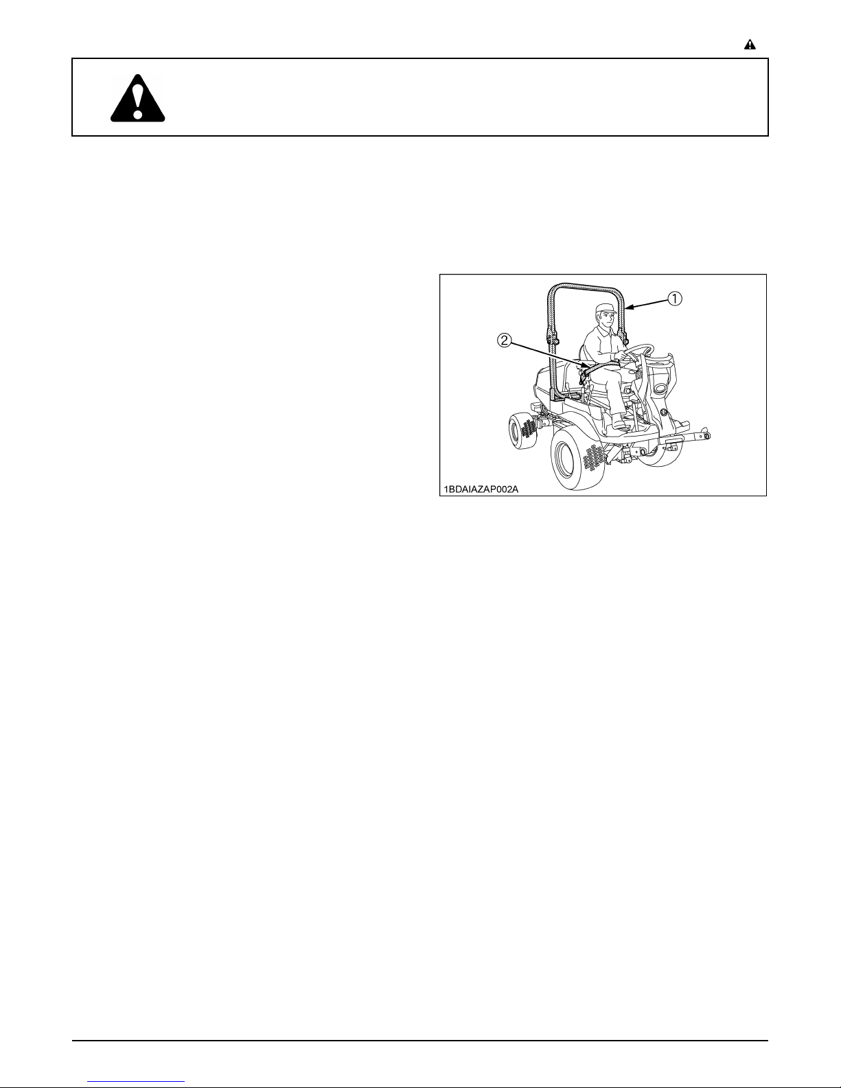
3. KUBOTA recommends the use of a Roll Over
Protective Structures (ROPS) and seat belt in almost
all applications. This combination will reduce the risk
of serious injury or death, should the machine be
upset.
The machine is equipped with a foldable ROPS, which
may be temporarily folded down only when absolutely
necessary for areas with height constraints.
(There is no operator protection provided by the ROPS
in the folded position. For operator safety the ROPS
should be placed in the upright and locked position
and the seat belt fastened for all other operations.)
If the ROPS is loosened or removed for any reason,
make sure that all parts are reinstalled correctly before
operating the machine.
Never modify or repair a ROPS because welding,
bending, drilling, grinding, or cutting may weaken the
structure.
A damaged ROPS structure must be replaced, not
repaired or revised.
If any structural member of the ROPS is damaged,
replace the entire structure at your local KUBOTA
Dealer.
(1) ROPS
(2) Seat belt
4. Always use the seat belt when the ROPS is upright. Do
not use the seat belt without a ROPS being upright.
Check the seat belt regularly and replace if frayed or
damaged.
5. The exhaust gas from the muffler is very hot. To
prevent fire, do not expose dry grass, mowed grass, oil
or any other combustible materials to exhaust gas.
Use a spark arrester where required. Also keep the
engine and muffler clean all the time. Replace the
muffler if it has a fault.
6. Never wear loose, torn, or bulky clothing. It may catch
on moving parts or controls, leading to the risk of
accident. Safety boots or shoes, eye and hearing
protection, gloves, dust mask, etc. are recommended.
7. Do not wear radio or music headphones while
operating the machine.
Safe operation requires your full attention.
8. Carefully check the vicinity before operating machine
or any implement attached to it. Clear the work area of
objects (wires, rocks, etc.) that might be picked up and
thrown. Check for overhead clearance which may
interfere with a ROPS.
9. Do not operate machine or any implement attached to
it while under the influence of alcohol, drugs, or other
substances or while fatigued.
10.Check brakes, and other mechanical parts for faulty
adjustment and wear. Replace worn or damaged parts
promptly. Check the tightness of all nuts and bolts
regularly. (For further details, see "MAINTENANCE"
section.)
Page 10

SAFE OPERATION-2
11.Keep the machine and attachments in good operating
condition and keep safety devices in place and in
proper working condition.
12.Do not modify the machine. Unauthorized modification
may affect the function of the machine, which may
result in personal injury.
13.Keep all shields and guards in place. Replace all
missing or damaged items for your safety.
14.Never allow any bystanders around or near machine
during operation.
Be sure the area is clear of other people before
mowing.
Stop machine if anyone enters the area.
15.Before allowing other people to use your machine,
explain proper operation to them and have them read
this manual before operation.
16.Never allow passengers or non-qualified operators on
the machine at any time. You must operate the
machine from the seat only.
17.In addition to the design and configuration of
equipment, hazard control and accident prevention
are dependent on the awareness, concern, and
prudence of personnel involved in the operation,
transport, maintenance of facilities.
18.Keep your machine clean. Dirt, grease, and trash
accumulations may contribute to fires or lead to
personal injury.
19.Use only attachments recommended by KUBOTA.
Use proper ballast to front or rear of machine to reduce
the risk of upsets. Follow the "Safe Operation"
procedures, specified in the Equipment's Manual.
2. OPERATING
C Starting
1. Never start the engine or operate levers from
anywhere other than the seat.
2. Before starting the engine make sure that all levers
and speed control pedal are in neutral, the parking
brake is engaged, and Power Take Off (PTO) is
disengaged.
Fasten the seat belt if the ROPS is upright.
3. Do not start the engine while tilting the deck.
4. Do not start the engine by shorting across starter
terminals or by bypassing the safety start switch. The
machine may start and move if normal starting circuitry
is bypassed.
5. Do not operate or idle engine in a poorly ventilated
area. Exhaust gas contains carbon monoxide, a
colorless, odorless gas they can be poisonous if not
properly ventilated.
C Working
1. Watch where you are going at all times. Watch for and
avoid obstacles. Be alert near trees and other
obstructions.
2. To avoid tip over, slow down when turning on uneven
terrain or before stopping.
3. Park the machine on a firm, level surface.
4. Do not drive at high speeds or turn the machine when
the differential is locked.
5. Know what is behind you before backing up. Look to
the rear before and while backing up. Do not mow
while in reverse unless absolutely necessary and
make sure the area immediately behind you is clear of
obstructions or holes and small children. Use extra
caution when the machine is equipped with the grass
catcher. Your view to the rear is restricted.
6. When working in groups, always let others know what
you are doing ahead of time.
7. Do not drive the machine on streets or highways.
Watch for traffic when you cross roads or operate near
roads.
8. Be aware of the mower discharge direction and do not
point it at anyone.
9. When using any attachments, never direct discharge
material toward bystanders. Do not allow anyone near
the attachments while in operation.
Do not mow when bystanders are present in the
mowing area.
10.To reduce fire hazards, keep the engine exhaust area
free of debris.
11.Be sure rotating blades and engine are stopped and
the key is removed before placing hands or feet near
blades and cleaning blockages or unclogging chute.
12.Shut the engine off and wait for all movement to stop
before unclogging the chute of the grass catcher. [if
equipped]
13.Always inspect the mower and the grass catcher [if
equipped] after striking any foreign object. This will
insure that all mower and grass catcher parts are safe
and secure and not damaged.
Repair or replace any damaged parts before restarting.
14.Operate during daylight or in bright artificial light.
15.Do not operate where machine could tip or slip.
Do not operate near ditches, holes, embankments, or
other terrain which may collapse under the machine's
weight. The risk of machine tip-over is increased when
the ground is loose or wet.
C Operation on slopes
Slopes are a major factor related to loss-of-control and tipover accidents, which can result in severe injury or death.
All slopes require extra caution. If you cannot back up the
slope or if you feel uneasy on it, do not mow it.
A Do not lift the grass container on a slope. [if equipped]
Page 11

DO
1. To avoid tip over, operate up and down slowly, not
across. Stay off hills and slopes too steep for safe
operation.
2. Remove obstacles such as rocks, tree limbs, etc.
3. Stay alert for holes in the terrain and other hidden
hazards. Keep away from drop-offs. Uneven terrain
could overturn the machine. Tall grass can hide
obstacles.
4. Follow KUBOTA's recommendations for wheel
weights or counterweights to improve stability.
5. The weight of grass in the grass container may
increase the possibility of tip over. [if equipped]
6. Keep all movement on slopes slow and gradual. Do
not make sudden changes in speed or direction.
7. Avoid starting or stopping on a slope. If tires lose
traction, disengage the blades and proceed slowly
straight down the slope.
8. Reduce speed and exercise extreme caution on
slopes and in sharp turns to prevent tip-over or loss of
control.
9. Use special caution when changing direction on
slopes.
10.Shift "High - Low Gear Shift Lever" to the Low position
when mowing or operating on slopes.
-3SAFE OPERATION
C Children
Tragic accidents can occur if the operator is not alert to
the presence of children. Children are attracted to the
machine and the mowing activity. Never assume that
children will remain where you last saw them.
1. Keep children out of the mowing area and under the
watchful care of another responsible adult.
2. Be alert and turn the machine off if children enter the
area.
3. Before and when backing, look behind and down for
small children.
4. Never carry children. They may fall off and be
seriously injured or interfere with safe machine
operation.
5. Never allow children to operate the machine, even
under adult supervision. Local regulation can restrict
the age of the operator.
6. Use extra care when approaching blind corners,
shrubs, trees, or other obstructions that might hide
children from sight.
C Operators, age 60 years and above
Data indicates that operators, age 60 years and above,
are involved in a large percentage of machine-related
injuries. These operators should evaluate their ability to
operate the machine safely enough to protect themselves
and others from serious injury.
DO NOT
1. Do not turn on slopes unless necessary and then turn
slowly and gradually downhill, if possible.
2. Do not mow near drop-offs, ditches, or embankments.
The machine could suddenly turn over if a wheel falls
over the edge of a cliff or ditch, or if an edge caves in.
3. Do not mow on wet grass. Reduced traction could
cause sliding.
4. Do not try to stabilize the machine by putting your foot
on the ground.
5. Do not use the grass catcher on steep slopes. [if
equipped]
6. Do not stop or start suddenly when going uphill or
downhill.
7. Never "freewheel". Do not let the machine travel
downhill with HST pedal at neutral position.
C Stopping
1. Make sure that the machine and all attachments have
come to complete stop before dismounting.
2. Before dismounting, disengage the PTO, lower all
implements, place all control levers in their neutral
positions, apply parking brake, turn off the engine and
remove the key.
3. Do not park the machine on a steep incline. Park on
relatively flat areas.
3. USING THE PTO
1. Before installing or using PTO-driven equipment, read
the manufacturer's manual and review the safety
labels attached to the equipment.
2. Wait until all moving components have completely
stopped before connecting, disconnecting, adjusting,
cleaning, or servicing any PTO-driven equipment.
3. Use the PTO with KUBOTA approved attachments.
The speed of the PTO:
F2690E, F2690 2545 rpm at 3000 engine rpm
F3990 2583 rpm at 2500 engine rpm
Page 12
SAFE OPERATION-4
4. USING THE LIFT LINK
1. Use lift link only with authorized attachments designed
for lift link usage.
2. When using a lift link mounted attachment, be sure to
install the adequate counter ballast weight specified in
the attachment's manual.
3. When moving the machine a long distance, set the
implement lowering control in the "LOCK" position to
hold the implement in the raised position.
4. Do not turn the knob quickly.
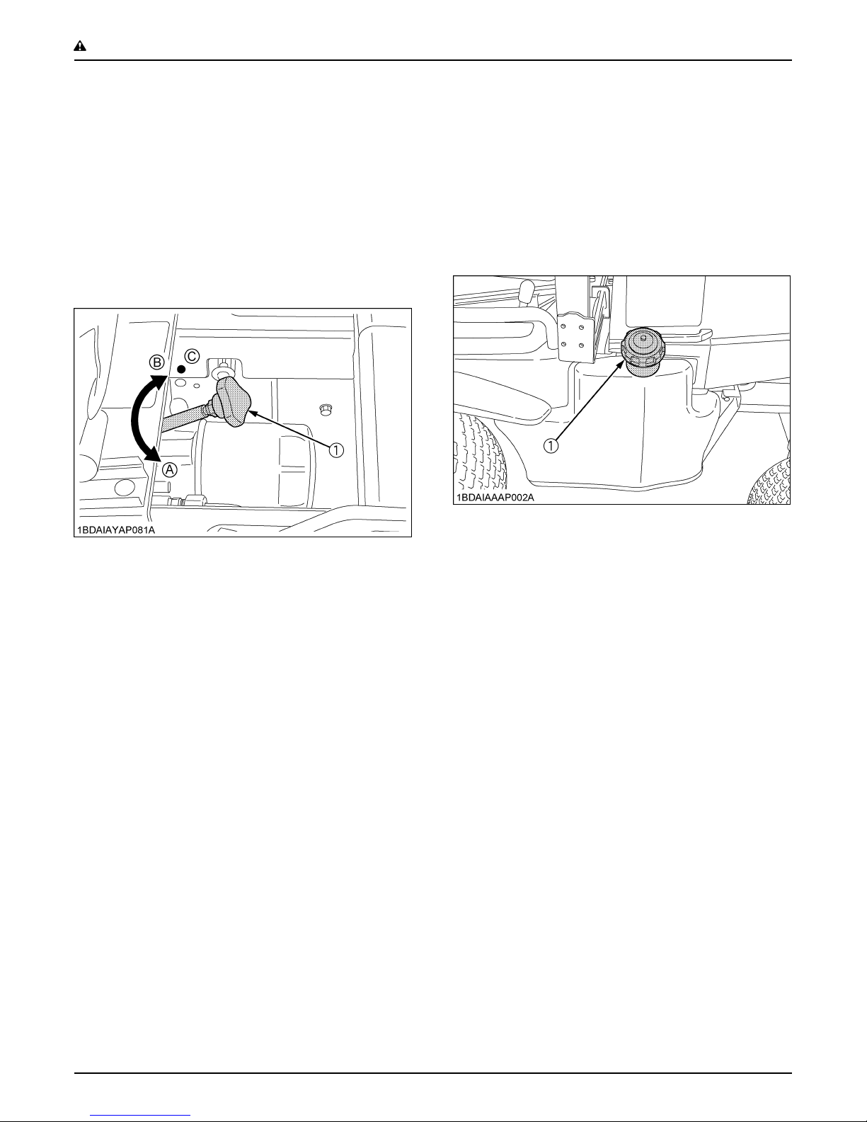
6. SERVICING
1. Before servicing the machine, park the machine on a
firm, level surface, set the parking brake, stop the
engine and remove the key.
2. Allow the machine to cool off before servicing the
engine, muffler, etc.
3. Always stop the engine before refueling. Avoid spills
and overfilling. Wipe up spilled fuel immediately.
(1) Fuel tank cap
(1) Lift link lowering speed control knob
(A) "FAST": Turn counterclockwise slowly
(B) "SLOW": Turn clockwise
(C) "LOCK": Turn clockwise to the end
5. TRANSPORTING
1. Disengage power to attachment(s) when transporting
or not in use.
2. Do not tow this machine. Use a suitable truck or trailer
when transporting on public roads.
3. It is recommended that this machine not be used on
public roads.
4. Use extra care when loading or unloading the machine
into a trailer or truck.
5. Keep attachment(s) low when transporting.
6. Move very slowly when attachment is removed.
4. Use extra care in handling diesel fuel.
(1) Use only an approved container.
(2) Do not remove fuel cap or refuel with the engine
running. Allow engine to cool before refueling. Do
not smoke while refueling or when standing near
fuel.
(3) Do not refuel the machine indoors and always
clean up spilled fuel or oil.
(4) Do not store the machine or fuel container inside
where there is an open flame, such as a water
heater.
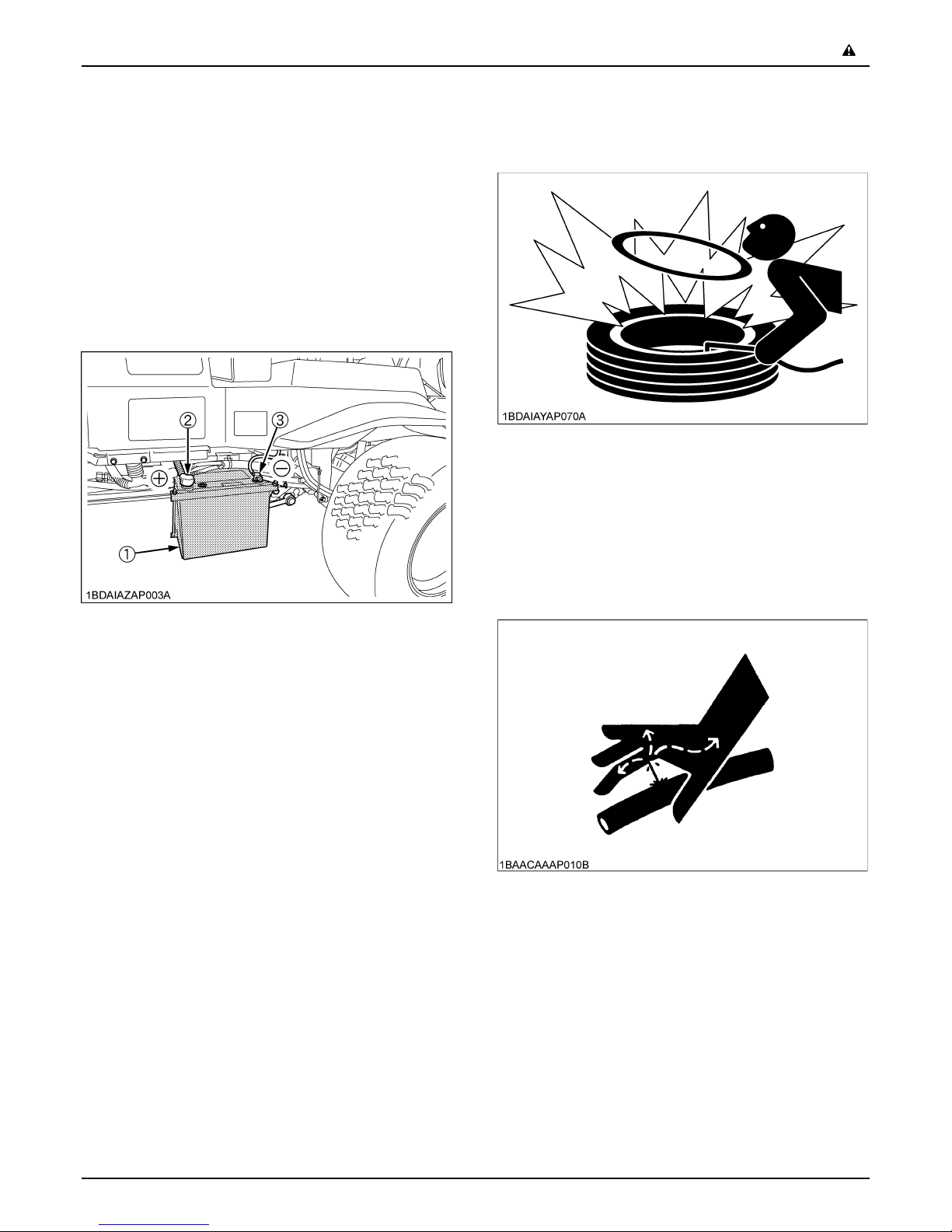
5. Do not smoke when working around the battery.
Keep all sparks and flames away from battery. The
battery presents an explosion hazard because it gives
off hydrogen and oxygen...especially when
recharging.
6. Before "JUMP STARTING" a dead battery, read and
follow all of the instructions to help protect the
alternator from damage due to extreme load changes.
(See "JUMP STARTING" in "OPERATING THE
ENGINE" section.)
Batteries contain sulfuric acid and produce explosive
gases. Follow the instructions below to prevent
personal injury.
A Wear eye and skin protection.
A Keep sparks and flame away.
A Always have adequate ventilation while charging
or using the battery.
7. Keep first aid kit and fire extinguisher available at all
times.
Page 13
-5SAFE OPERATION
8. Disconnect the battery's negative (-) cable before
working on or near electric components.
9. Do not use or charge the refillable type battery if the
fluid level is below the LOWER (lower limit level) mark.
Otherwise, the battery component parts may
prematurely deteriorate, which may shorten the
battery's service life or cause an explosion. Check the
fluid level regularly and add distilled water as required
so that the fluid level is between the UPPER and
LOWER levels.
10.To avoid sparks from an accidental short circuit,
always disconnect the battery's negative (-) cable first
and connect it last.
(1) Battery
(2) Positive cable (+)
(3) Negative cable (-)
15.Always maintain the correct tire inflation pressure. Do
not inflate tires above the recommended pressure
shown in the Operator's Manual.
16.Securely support the machine when changing wheels.
17.Make sure that wheel bolts have been tightened to the
specified torque.
18.Escaping hydraulic fluid under pressure has sufficient
force to penetrate the skin causing serious personal
injury. Before disconnecting lines, be sure to relieve all
pressure. Before applying pressure to the system,
make sure all connections are tight and that lines,
pipes, and hoses are not damaged.
11.Do not remove the radiator cap while coolant is hot.
When cool, slowly rotate cap to the first stop and allow
sufficient time for excess pressure to escape before
removing the cap completely. If the machine has a
coolant recovery tank, add coolant there instead of the
radiator.
12.Provide adequate support when changing wheels or
the wheel.
13.Make sure that wheel nuts have been tightened to the
specified torque.
14.Do not attempt to mount a tire on a rim. This should be
done by a qualified person with the proper equipment.
Page 14
SAFE OPERATION-6
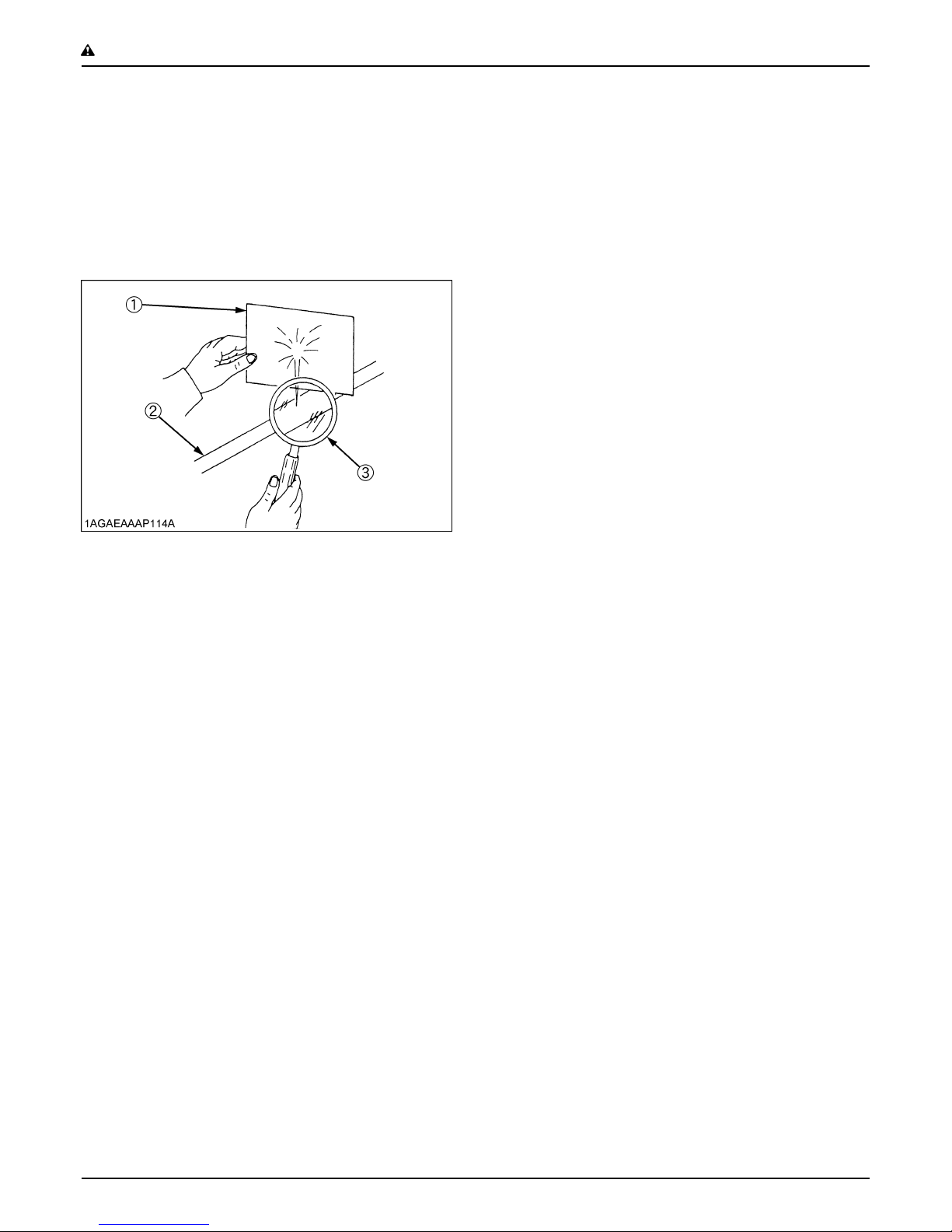
19.Fluid escaping from pinholes may be invisible. Use a
piece of cardboard or wood to search for suspected
leaks: do not use hands. Use safety goggles or other
eye protection.
If injured by escaping fluid, see a medical doctor at
once. Serious infection or reaction will result if proper
medical treatment is not administered immediately.
This fluid can produce gangrene or severe allergic
reaction.
(1) Cardboard
(2) Hydraulic line
(3) Magnifying glass
20.Do not make adjustments or repairs with the engine
running.
21.Keep machine free of grass, leaves, or other debris
build-up.
22.Do not run a machine inside a closed area.
7. STORAGE
1. Keep the machine and fuel supply in a secure area
and remove the key to prevent children or others from
playing or tampering with them.
2. Do not store the machine in an area that may ignite
fuel vapor. Allow the engine to cool before storing.
3. To avoid the danger of exhaust fume poisoning, do not
operate the engine in a closed building without
adequate ventilation.
4. To reduce fire hazards, clean the machine thoroughly
before storage. Dry grass and leaves around the
engine and mufflers may ignite.
Page 15
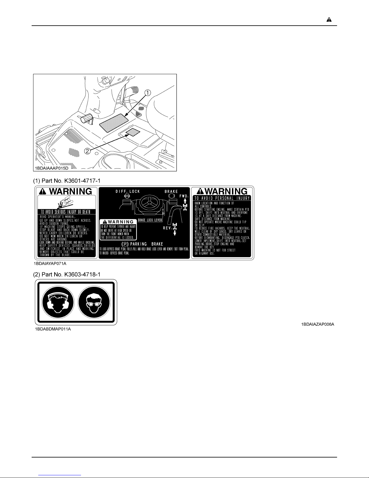
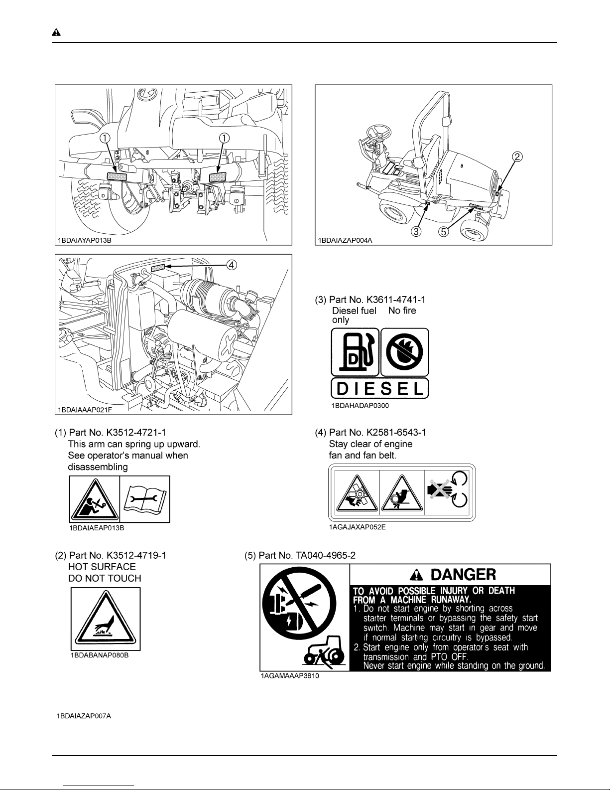
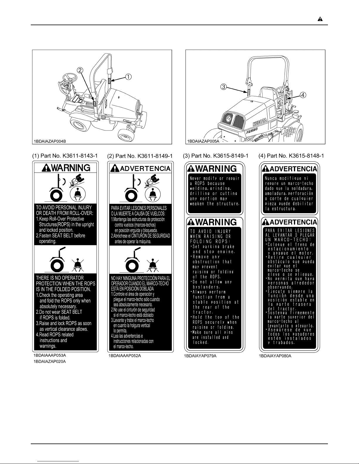
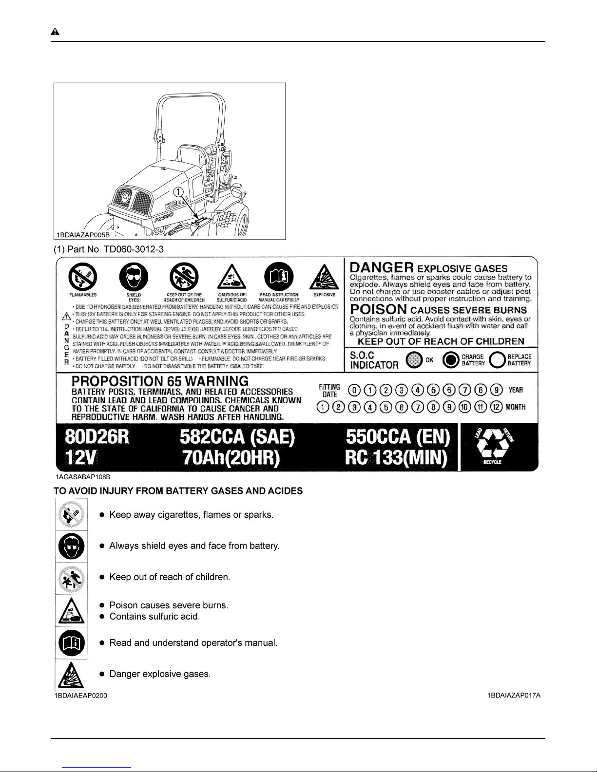
8. DANGER, WARNING AND CAUTION LABELS
-7SAFE OPERATION
Page 16
SAFE OPERATION-8
Page 17
-9SAFE OPERATION
Page 18
SAFE OPERATION-10
Page 19

-11SAFE OPERATION
9. CARE OF DANGER, WARNING AND CAUTION LABELS
1. Keep danger, warning and caution labels clean and free from obstructing material.
2. Clean danger, warning and caution labels with soap and water, dry with soft cloth.
3. Replace damaged or missing danger, warning and caution labels with new labels from your local KUBOTA Dealer.
4. If a component with danger, warning and caution label(s) affixed is replaced with new parts, make sure new label(s) is
(are) attached in the same location(s) as the replaced component.
5. Mount new danger, warning and caution labels by applying on a clean dry surface and pressing any bubbles to outside
edge.
Page 20

Page 21
SERVICING OF MACHINE
After reading this manual thoroughly, you will find that you
can do some of the regular maintenance yourself. Your
dealer is interested in helping you get the best
performance from your new machine and wants to help
you get the most value from it. When in need of parts or
major service, be sure to see your local KUBOTA Dealer.
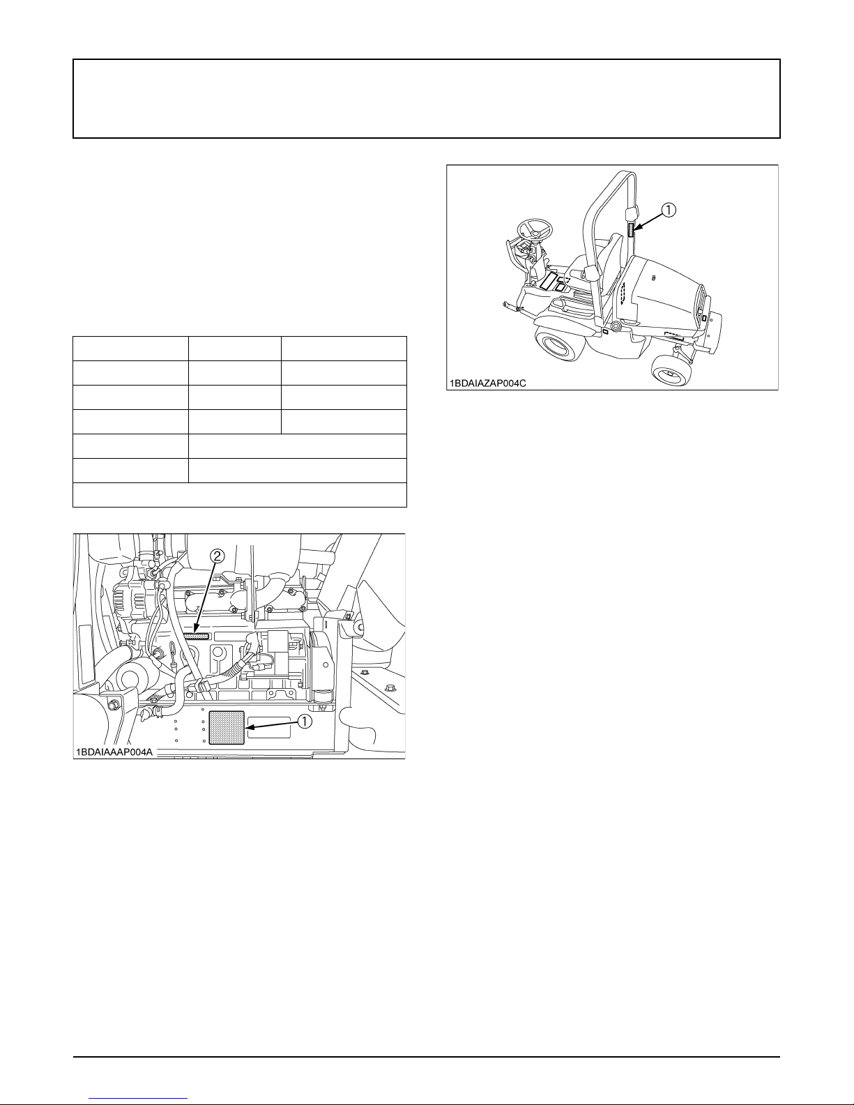
When in need of parts, be prepared to give your dealer the
serial number of the machine, ROPS and engine.
Locate the serial numbers now and record them in the
space provided.
Type Serial No.
Machine
1SERVICING OF MACHINE
Engine
ROPS
Date of Purchase
Name of Dealer
(To be filled in by purchaser)
(1) Machine serial No.
(2) Engine serial No.
(1) ROPS serial No.
C Warranty
This machine is warranted under the Kubota Limited
Express warranty, a copy of which may be obtained from
your selling dealer. No warranty shall, however, apply if
the machine has not been handled according to the
instruction given in the Operator's Manual even it is within
the warranty period.
C Scrapping the machine and its procedure
To put the machine out of service, correctly follow the
local rules and regulations of the country or territory where
you scrap it. If you have questions, consult your local
KUBOTA Dealer.
Page 22

2 SPECIFICATIONS
SPECIFICATIONS
Model F2890 F3690
Model D1105 V1505
Engine gross power (SAE) *1 kW (HP) 20.6 (28) 26.5 (36)
Type Indirect Injection. Vertical water - cooled, 4cycle diesel
Number of cylinders 3 4
Bore and stroke mm 78 x 78.4
Total displacement cm 1123 1498
Engine
Capacities
Rated revolution rpm 3000
Low idling revolution rpm 1300 to 1400
Fuel
Starter Electric starter with battery, glow plug, 12 V, 1.4 kW
Lubrication Forced lubrication by gear pump
Cooling Liquid with pressurized radiator
Battery 12 V, RC: 133 min, CCA: 582 A
Fuel tank L 61
Engine crankcase (with filter) *3 L 3.5 5.0
Engine coolant L 4.6
Recovery tank L 0.6
Transmission case L 14
Rear axle differential case L 1.5
Rear axle gear case L 0.5
Overall length mm 2450
Overall width mm 1370
Diesel fuel No.1 (S-15) [below -10 ]
Diesel fuel No.2 (S-15)
Overall height
Dimensions
Wheelbase mm 1300
Min. ground clearance mm 185
Tread
Weight (W/O mower deck) kg 770 788
Without ROPS mm 1350
With ROPS mm 1985
Front mm 1063
Rear mm 1020
Page 23

Model F2890 F3690
3SPECIFICATIONS
Traveling
system
PTO
Front
Tires
Rear
Forward
Traveling
speeds *2
Reverse
Steering Power, hydrostatic
Transmission
Brake Wet disk type
Min. turning radius mm 750 (Inside of Front Tire)
Front Bevel gear
Differential
Rear Bevel gear
4WD system Dual - Acting Overrunning 4WD
Revolution 1 speed (2545 rpm at 3000 engine rpm)
Drive system
Clutch type Wet multi plates
Low 0 to 9 km/h
High 0 to 20 km/h
Low 0 to 4.8 km/h
High 0 to 11 km/h
24 x 12 - 12
(4PR) Turf
18 x 9.5 - 8
(4PR) Turf
Main - hydrostatic transmission. High - Low gear shift
(2 forward, 2 reverse)
Shaft drive. KUBOTA 10 tooth involute spline
(2545 rpm)
24 x 12 - 12
(4PR) Turf
18 x 9.5 - 8
(4PR) Turf
PTO brake Wet single plate
(Specifications and design subject to change without notice)
NOTE:
*1 Manufacture's estimate
*2 At 3000 engine rpm
*3 Oil amount when the oil level is at the center of the oil level gauge
Page 24
4 IMPLEMENT LIMITATIONS
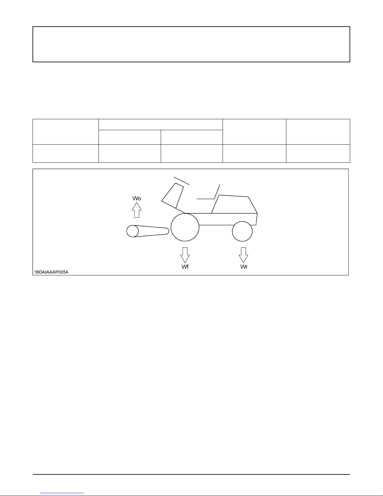
IMPLEMENT LIMITATIONS
The KUBOTA Machine has been thoroughly tested for proper performance with implements sold or approved by KUBOTA.
Use of implements which exceed the maximum loading weight listed below, or which are not recommended for use with
the KUBOTA Machine may result in malfunctions or failures of the machine, damage to other property and injury to the
operator or others. (Any malfunctions or failures of the machine resulting from use with improper implements are not
covered by the warranty.)
Maximum loading weight Lift link end maximum
Front axle Wf Rear axle Wr
loading weight
Wo
Maximum total weight
F2890
F3690
900 kg 600 kg 260 kg 1500 kg
Page 25
5INSTRUMENT PANEL AND CONTROLS
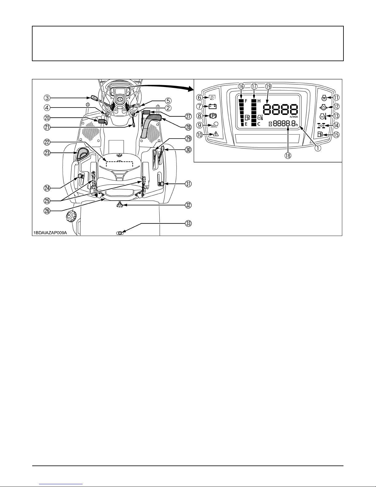
INSTRUMENT PANEL AND CONTROLS
ILLUSTRATED CONTENTS ILLUSTRATED CONTENTS
INSTRUMENT PANEL, SWITCHES and
HAND CONTROLS
(1) Liquid crystal display................................................... 25 (18) Hourmeter............................................................ 26
(2) Key switch.................................................................. 11 (19) Tachometer.......................................................... 26
(3) Throttle lever............................................................... 22 (20) Differential lock pedal........................................... 23
(4) Head light switch......................................................... 19 (21) Parking brake lever.............................................. 9
(5) Steering wheel tilt lever............................................... 19 (22) Globe box............................................................. 18
(6) PTO clutch indicator................................................... 9 (23) Cup holder
(7) Electrical charge warning indicator............................. 24 (24) 4WD lock lever (4WD only).................................. 21
(8) Parking brake warning indicator................................ 9 (25) Seat belt............................................................... 19
(9) Head light indicator................................................... 19 (26) Operator's seat..................................................... 18
(10) Master system warning indicator............................... 24 (27) Brake pedal.......................................................... 22
(11) Glow plug indicator................................................... 9 (28) Speed control pedal (HST pedal)......................... 23
(12) Engine oil pressure warning indicator....................... 24 (29) High - Low gear shift lever..................................... 21
(13) Engine overheat warning indicator............................ 24 (30) Hydraulic lift lever................................................. 20
(14) 4WD indicator........................................................... 21 (31) PTO lever............................................................. 22
(15) Fuel level indicator.................................................... 9 (32) Lift link lowering speed control knob.................... 20
(16) Fuel gauge................................................................ 25 (33) Hood lock lever.................................................... 35
(17) Coolant temperature gauge...................................... 25
CONTROLS
Page 26
6MOWER MOUNTING
MOWER MOUNTING
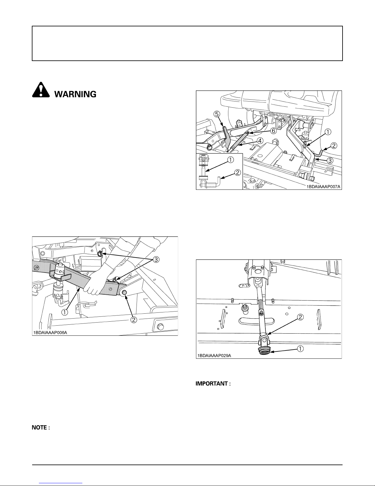
MOUNTING THE MOWER
To avoid serious injury:
A Before mounting the mower deck, read and
understand the use of the lift link lowering
speed control knob.
(See "Lift Link Lowering Speed Control Knob"
in "OPERATING THE MACHINE" section in the
operator's manual of the machine.)
A Place the PTO lever in the "DISENGAGE"
position.
A Place the High-Low gear shift lever in the
"NEUTRAL" position.
A The mower links (left hand, right hand) are
spring-loaded. Have an assistant hold the arm
in position when mounting the mower deck.
1. Move the mower deck under the mower links and
place the hydraulic lift lever in the "DOWN" position.
2. Attach the front end of the mower links to the mower
deck with clevis pins and set pins.
A For tilting up the mower, see "MOWER TILT UP"
section in the operator's manual of the mower.
(1) Lift rod
(2) Lock pin
(3) Mower link
6. Pull back the coupler of the universal joint.
Push the universal joint onto the PTO shaft until the
coupler locks.
Slide the universal joint backward and forward to
check that the universal joint is locked securely.
(4) Gas spring
(5) Tilt lever ("UNLOCKED" position)
(6) Rue ring cotter
(1) Mower link
(2) Set pin
(3) Clevis pin
3. Start the engine, raise the mower deck, lock the lift link
lowering speed control knob and shut off the engine.
4. Install the lift rods to the mower deck with lock pins and
lower the mower deck on the ground.
[RCK72P-F39 / RCK72R-F36]
5. Attach the gas spring to the mower link with the clevis
pin and the rue ring cotter.
A When operating the mower, make sure the tilt lever is
unlocked.
(1) Coupler
(2) Universal joint
A Finally pull the universal joint to see if it is locked tight
in position.
After mounting the mower deck, adjust the lift link lowering
speed.
(See "CONTROLS" in "INSTRUMENT PANEL AND
CONTROLS" section.)
Page 27

DISMOUNTING THE MOWER DECK
For dismounting the mower deck, reverse the above
procedures.
To avoid serious injury:
A The mower links (left hand, right hand) are
spring-loaded. Have an assistant hold the arm
in position when mounting the mower deck.
MOWER TILT UP
To avoid serious injury:
A Do not start the engine while tilting the mower
deck.
To avoid serious injury:
A Be sure to tilt the mower on a level surface and
the parking brake ON.
A Place the PTO lever in the "DISENGAGE"
position.
A Place the High-Low gear shift lever in the
"NEUTRAL" position.
7MOWER MOUNTING
BHow To Tilt Up
For detailed procedure, refer to the mower operator's
manual.
BHow To Mount Another Implement
For detailed procedure, refer to the implement instruction
manual.
Page 28

8 PRE-OPERATION CHECK
PRE-OPERATION CHECK
DAILY CHECK
To prevent trouble from occurring, it is important to know
the condition of the machine well. Check it before starting.
To avoid serious injury:
A Be sure to check and service the machine on a
level surface with the engine shut off and the
parking brake "ON" and implement lowered to
the ground.
Check item
- Walk around inspection
- Check engine oil level
- Check transmission oil level
- Check coolant level
- Clean air conditioner condenser screen
- Clean grill and radiator screen
- Check air cleaner evacuator valve
(When used in a dusty place)
- Check brake pedal
- Check indicators, gauges and meter
- Check lights
- Check wire harness
- Check seat belt
- Check movable parts
- Refuel
(See "DAILY CHECK" in "PERIODIC SERVICE"
section.)
- Care of danger, warning and caution labels
(See "DANGER, WARNING AND CAUTION LABELS"
in "SAFE OPERATION" section.)
Page 29

OPERATING THE ENGINE
To avoid serious injury:
A Read and understand "SAFE OPERATION" in
the front of this manual.
A Read and understand the danger, warning and
caution labels located on the machine.
A To avoid danger of exhaust fume poisoning, do
not operate the engine in a closed building
without proper ventilation.
A Never start the engine while standing on the
ground. Start the engine only from the
operator's seat.
A Make it a rule to set all shift levers to the
"NEUTRAL" positions and to place the PTO
lever in "OFF" position before starting the
engine.
(1) Brake pedal
(2) Parking brake lever
9OPERATING THE ENGINE
(A) "PARKING"
A Do not use starting fluid or ether.
A To protect the battery and the starter, make sure that
the starter is not continuously turned for more than 30
seconds.
STARTING THE ENGINE
1. Sit on the operator's seat.
2. Apply the parking brake.
To apply the parking brake:
Depress the brake pedal firmly and hold in position. Pull
and hold the parking brake lever, and release the brake
pedal.
To release the parking brake:
Depress the brake pedal and release slowly.
(1) Parking brake warning indicator
A It is recommended that the operator practice engaging
and disengaging the parking brake on a flat surface
without the engine running before operating the
machine for the first time.
Page 30

OPERATING THE ENGINE10
3. Make sure that the PTO lever is in the
"DISENGAGED" position.
(1) PTO lever : "ENGAGED"
: "DISENGAGED"
4. Make sure that the speed control pedal
is in the "NEUTRAL" position.
5. Make sure that the hydraulic lift lever is
in the "NEUTRAL" position.
(1) Hydraulic lift lever : "DOWN"
: "NEUTRAL"
: "UP"
6. Set the throttle lever 1/2 way forward.
(1) Speed control pedal (A) "FORWARD"
(B) "REVERSE"
(1) Throttle lever : "FAST"
: "SLOW"
7. Insert the key into the key switch and
turn clockwise 1 notch.
Make sure the easy checker lights are
"ON".
Page 31

11OPERATING THE ENGINE
C Check Easy Checker(TM) Lamps:
1. When the key is turned "ON", lamps (3) (4) should
come on. If trouble should occur at any location while
the engine is running, the indicator lamp
corresponding to problem will turn "ON".
2. Suppose that the engine coolant temperature is not
high enough yet. The glow plug indicator (4) also turns
"ON" when the key is turned "ON" to preheat the
engine and goes off automatically when preheat is
completed.
Illumination time of indicator varies according to the
temperature of coolant.
3. The PTO clutch indicator (1) comes on while PTO
lever is engaged "ON" and goes off when disengaged.
4. If the fuel level indicator (5) lights up, when fuel level is
very low, therefore add fuel and the light will turn
"OFF".
5. If the parking brake warning indicator (6) does not
illuminate, make sure the parking brake is set.
A Some of the Easy Checker(TM) lamps may illuminate
or start flashing depending on the positions of the
levers and switches.
A Daily checks with the Easy Checker(TM) only, are not
sufficient. Never fail to conduct daily checks carefully
by referring to Daily Check. (See "DAILY CHECK" in
"PERIODIC SERVICE" section.)
BKey Switch
(1) PTO clutch indicator
(2) Electrical charge warning indicator
(3) Engine oil pressure warning indicator
(4) Glow plug indicator
(5) Fuel level indicator
(6) Parking brake warning indicator
(7) Key switch
: "OFF" (Engine - Stop)
: "ON" (Engine - Run)
A Do not turn the key switch to the "START" position
while the engine is running.
A When the temperature is below 0 , run the engine at
medium speed to warm up the lubricant of the engine
and the transmission for at least 10 minutes. If the
machine is operated before the lubricant is warm
enough, the machine life will be shortened.
A Do not operate the machine under full load until it is
sufficiently warmed.
A Do not use starting fluid or ether.
A When the ambient temperature is less than -15 ,
remove the battery from the machine and store it
somewhere warm until the next operation.
: "PREHEAT" (Preheat)
: "START" (Engine - Start)
8. Turn the key switch to the "PREHEAT"
position clockwise, and hold it for about
5 seconds.
For the appropriate preheating time,
refer to the table below:
Temperature Preheating Time
Over 0 5 sec.
Below 0 10 sec.
Page 32

OPERATING THE ENGINE12
9. Turn the key switch to the "START"
position and release the key to the "ON"
position when the engine starts.
A Because of the safety devices, the engine may not be
started except when the PTO clutch is disengaged, the
brake pedal is fully depressed and the operator sits in
the seat.
BCold Weather Starting
When the ambient temperature is below -5 and the
engine is very cold. (If the engine fails to start after 10
seconds, turn off the key for 30 seconds. Then repeat
steps 8 and 9. To protect the battery and the starter, make
sure that the starter is not continuously turned for more
than 30 seconds.)
BBlock Heater (Option)
A block heater is available as an option from your local
dealer. It will assist you in starting your machine when the
ambient temperature is below -15 .
10. Check to see that all the lamps on the
Easy Checker(TM) are "OFF".
If the lamp is still on, immediately stop the engine and
determine the cause.
11. Warm the engine by running at medium
speed.
STOPPING THE ENGINE
1. Set the parking brake.
2. After slowing the engine to idle, turn the key switch to
the "OFF" position.
3. Remove the key.
4. Do not leave the key switch "ON" (key in the "ON"
position) as the battery will discharge when the engine
is not running.
WARMING UP
To avoid serious injury:
A Be sure to apply the parking brake during
warm-up.
For 5 minutes after engine start-up, allow engine to warm
up without applying any load. This is to allow oil to reach
every part of the engine. If load should be applied to the
engine without this warm-up period, problems may
develop such as seizure, breakage or premature wear.
BWarm-up and Transmission Oil in the Low
Temperature Range
Hydraulic oil serves as transmission oil and power
steering fluid. In cold weather, the oil may be cold with
increased viscosity. This can cause delayed oil circulation
or abnormally low hydraulic pressure for some time after
engine start-up. This in turn creates problems with the
hydraulic system or may damage the hydraulic clutch.
To prevent the above, observe the following instructions:
Warm up the engine at about 50% of rated rpm according
to the table below:
Atmospheric temperature
Warm-up time
requirement Higher
Higher than 0 Approx. 5 minutes
-10 to 0 5 to 10 minutes
-20 to -10 10 to 15 minutes
Below -20 More than 15 minutes
A Do not operate unless the engine is well warmed up. If
operation is attempted while the engine is still cold, the
hydraulic mechanism will not function properly and its
service life will be shortened.
A If noises are heard after the hydraulic control lever has
been activated and the implement is lifting, the
hydraulic mechanism is not adjusted properly. Unless
corrected, the unit will be damaged. Contact your local
KUBOTA Dealer for adjustment.
Page 33

13OPERATING THE ENGINE
BEngine Stop Lever and Fuel Valve (Inside
the Hood)
The engine stops when the key switch is turned "OFF". If
the engine does not stop, make sure the speed control
pedal is in the "NEUTRAL" position, the PTO lever is
"OFF", the mower lowered to the ground and apply the
parking brake, then carefully get off the machine. Open
the hood and pull engine stop lever (Red mark) and hold
it until the engine stops. Then contact your local KUBOTA
Dealer immediately.
To avoid serious injury:
A Do not operate the machine until the engine
stop system is repaired.
(1) Engine stop lever
JUMP STARTING
To avoid serious injury:
A Keep cigarettes, sparks, and flames away from
battery.
A If machine battery is frozen, do not jump start
engine.
A Do not connect other end of negative (-) jumper
cable to negative (-) terminal of machine
battery.
When jump starting the engine, follow the instructions
below to safely start the engine.
1. Bring helper vehicle with a battery of the same voltage
as the disabled machine within easy cable reach.
"THE VEHICLES MUST NOT TOUCH".
2. Apply the parking brakes of both vehicles and put the
shift levers in neutral. Shut the engine off.
3. Put on safety goggles and rubber gloves.
4. Ensure the vent caps are securely in place.
(if equipped)
5. Attach the red clamp to the positive (red, (+) or pos.)
terminal of the dead battery and clamp the other end
of the same cable to the positive (red, (+) or pos.)
terminal of the helper battery.
6. Clamp the other cable to the negative (black, (-) or
neg.) terminal of the helper battery.
7. Clamp the other end to the engine block or frame of
the disabled machine as far from the dead battery as
possible.
8. Start the helper vehicle and let its engine run for a few
moments. Start the disabled machine.
9. Disconnect the jumper cables in the exact reverse
order of attachment. (Steps 7, 6 and 5).
Page 34

OPERATING THE ENGINE14
(1) Dead battery
(2) Jumper cables
(3) Frame
(4) Helper battery
Connect cables in numerical order.
Disconnect in reverse order after use.
A This machine has a 12 volt negative (-) ground starting
system.
A Use only same voltage for jump starting.
A Use of a higher voltage source on machine could
result in severe damage to machine electrical system.
Use only matching voltage source when "Jump
starting" a low or dead battery condition.
Page 35

OPERATING THE MACHINE
15OPERATING THE MACHINE
OPERATING NEW MACHINE
How a new machine is operated and maintained will
determine the life of the machine.
A new machine just off the factory production line has
been tested, but the various parts are not accustomed to
each other, so care should be taken to operate the
machine for the first 50 hours at a slower speed and avoid
excessive work or operation until the various parts
become "broken-in." The manner in which the machine is
handled during the "breaking-in" period greatly affects the
life of your machine. Therefore, to obtain the maximum
performance and the longest life of the machine, it is very
important to properly break-in your machine. In handling a
new machine, the following precautions should be
observed.
BChanging Lubricating Oil for New
Machines
The lubricating oil is especially important in the case of a
new machine. The various parts are not "broken-in" and
are not accustomed to each other; small metal grit may
develop during the operation of the machine; and this may
wear out or damage the parts. Therefore, care should be
taken to change the lubricating oil a little earlier than
would ordinarily be required.
For further details of change interval hours, see
"SERVICE INTERVALS" in "MAINTENANCE" section.
BEngine Break-in
After the first 50 hours of operation, change the engine oil
and filter. (See "EVERY 200 HOURS" in "PERIODIC
SERVICE" section.)
BMachine Break-in
After the first 400 hours of operation, change the
transmission fluid.
After the first 50 hours of operation, change the oil filter
cartridge. (See "EVERY 400 HOURS" in "PERIODIC
SERVICE" section.)
To avoid serious injury:
A Do not allow any person other than the driver to
ride on the machine.
A Do not drive the machine close to the edges of
ditches or banks which may collapse under the
weight of the machine, especially when the
ground is loose or wet.
A Slow down before turning.
A To avoid tip over, operate up and down slopes,
not across. Avoid sudden starts and stops on
slopes. Slow down, and use extra caution when
changing direction on a slope. Do not use the
machine on steep incline.
Park the machine on a firm, level surface.
A Watch where you are going at all times. Watch
for and avoid obstacles. Be alert at curbs, near
trees, and other obstructions and hidden
hazards.
A Do not drive a machine on streets or highways.
Watch for traffic when you cross roads or
operate near roads.
A Look to the rear before and when backing.
Make sure the area immediately behind you is
clear of obstructions, holes and small children.
Use extra caution when a machine is equipped
with Grass Catcher.
Page 36

OPERATING THE MACHINE16
OPERATING FOLDABLE ROPS
To avoid serious injury or death:
A Always use the seat belt when the ROPS is
installed.
A Do not use the seat belt if a foldable ROPS is
down or there is no ROPS.
To avoid serious injury:
A When raising or folding the ROPS, apply
parking brake, stop the engine and remove the
key.
Always perform function from a stable position
from the rear of the machine.
A Fold the ROPS down only when absolutely
necessary and fold it up and lock it again as
soon as possible.
A Before proceeding to fold the ROPS, check for
any possible interference with installed
implements and attachments.
If interference occurs, contact your local
KUBOTA Dealer.
3. Fold the ROPS.
To avoid serious injury:
A Hold the ROPS tightly with both hands and fold
the ROPS slowly and carefully.
(1) ROPS
4. Align lock pin holes and insert both lock pins and
secure them with the hair pins.
BTo Fold the ROPS
1. Unscrew the knob bolts 1 to 2 turns.
2. Remove both lock pins.
(1) Lock pin
(2) Hair pin
(3) Knob bolt
To avoid serious injury:
A Make sure that both lock pins are properly
installed and secured with the hair pins.
(1) Lock pin
(2) Hair pin
Page 37

17OPERATING THE MACHINE
BTo Raise the ROPS to Upright Position
1. Remove both hair pins and lock pins.
(1) Lock pin
(2) Hair pin
2. Raise ROPS to the upright position.
To avoid serious injury:
A Hold the ROPS tightly with both hands and
raise the ROPS slowly and carefully.
BAdjustment of Foldable ROPS
A Adjust free fall of the ROPS upper frame regularly.
A If you feel less friction when folding the ROPS, tighten
the nut (1) until you feel the right friction in the
movement.
(1) Nut
3. Align lock pin holes, insert both lock pins and secure
them with the hair pins.
4. Tighten the knob bolts slightly.
To avoid serious injury:
A Make sure that both lock pins are properly
installed as soon as the ROPS is in the upright
position and secured with the hair pins.
(1) Lock pin
(2) Hair pin
(3) Knob bolt
Page 38

OPERATING THE MACHINE18
STARTING
1. Adjust the operator's position and
apply the seat belt.
BOperator's Seat
To avoid serious injury:
A Make adjustments to the seat only while the
machine is stopped.
A Make sure that the seat is completely secured
after each adjustment.
A Do not allow any person other than the driver to
ride on the machine.
C Travel adjustment
Unlock the travel adjust lever and slide the seat backward
or forward, as required. The seat will lock in position when
the lever is released.
To avoid serious injury:
A Use extra caution when unlocking the travel
adjust lever because the seat might slide
forward by itself.
C Suspension adjustment
Turn the suspension adjust knob to achieve the optimum
suspension setting.
C Lumbar support adjustment
Turn the lumbar support adjust knob to the desired
position.
C Backrest tilt adjustment
Turn the backrest tilt adjust knob to the desired angle.
C Arm rest
Arm rest may be set at upright position if desired.
(1) Travel adjust lever
(2) Suspension adjust knob
(3) Indicator of suspension
(4) Backrest tilt adjust knob
(5) Lumbar support adjust knob
(6) Arm rest
(7) Arm rest angle adjust knob
C Arm rest angle adjustment
Turn the arm rest angle adjust knob to the desired angle.
A After adjusting the operator's seat, be sure to check
and see that the seat is properly locked.
BGlobe Box
(1) Globe box
Page 39

19OPERATING THE MACHINE
BSteering Wheel Tilt Lever
By pulling the steering wheel tilt lever upward, the lock is
released and the steering wheel can be adjusted to a
desired tilt angle from the choice of 4 settings.
(1) Steering wheel tilt lever
BSeat Belt
2. Selecting Light Switch Positions
BHead Light Switch
Turning the light switch clockwise illuminates the
headlight.
To avoid serious injury or death:
A Always use the seat belt when the ROPS is
installed.
A Do not use the seat belt if a foldable ROPS is
down or there is no ROPS.
Adjust the seat belt for proper fit and connect to the
buckle. The seat belt is an auto-locking retractable type.
(1) ROPS
(2) Seat belt
.......................Head light OFF
.....................Head light ON
3. Start the engine.
See "OPERATING THE ENGINE"
section.
Page 40

OPERATING THE MACHINE20
4. Raising the implement
BLift Link Lowering Speed Control Knob
To avoid serious injury:
A Fast lowering speed may cause damage or
injury. Lowering speed of the implement
should be adjusted to 2 or more seconds.
The lowering speed of the lift link can be controlled by
adjusting the lift link lowering speed control knob.
BHydraulic Lift Lever
The hydraulic lift lever is used to raise and lower the
implement used with the machine (ex. Mower).
To lower the implement, push the lever FORWARD.
To raise it, pull the lever BACKWARD.
(1) Hydraulic lift lever : "DOWN"
: "NEUTRAL"
: "UP"
(1) Lift link lowering speed control knob
(A) "FAST": Turn counterclockwise slowly
(B) "SLOW": Turn clockwise
(C) "LOCK": Turn clockwise to the end
C How to adjust the Lowering Speed
1. Park the machine on a level surface and apply the
parking brake.
2. Move the PTO lever in the "DISENGAGE" position.
3. Move the High-Low gear shift lever in the "NEUTRAL"
position.
4. Start the engine and raise the implement fully.
5. Turn the lift link lowering speed knob clockwise to the
"LOCK" position.
6. Stop the engine and move the Hydraulic lift lever in the
"DOWN" position.
7. Turn the knob counterclockwise slowly to adjust the
lowering speed.
A Before adjustment, never check near or under the
implement.
A Turn the knob slowly and carefully to avoid sudden fall
of the implement.
A Do not operate until the engine is warmed up. If
operation is attempted when the engine is still cold, the
hydraulic system may be damaged.
A Do not operate at slow Engine rpm. Move the throttle
lever above 1/2.
A If noises are heard when implement is lifting after the
hydraulic lift lever has been activated, the hydraulic
mechanism is not adjusted properly. Contact your
local KUBOTA Dealer for adjustment.
Page 41

21OPERATING THE MACHINE
5. Selecting the Travel Speed
BHigh-Low Gear Shift Lever
To avoid serious injury or death:
A Shift "High-Low Gear Shift Lever" to the Low
position before mowing or operating on slopes.
High-Low gear shift lever moves in the form of an "I" in 3
stages, "LOW", "NEUTRAL" and "HIGH".
By using the speed control pedal and high-low gear shift
lever, additional speeds can be obtained.
A To shift high-low gear shift lever, stop the machine
before attempting to proceed with speed change.
B4WD Lock Lever
To avoid serious injury or death:
A Do not change the 4WD lock lever to the Dual-
Acting Overrunning 4WD position on slopes.
Set it Full time 4WD position on slopes. Do not
change the 4WD lock lever to the Full time 4WD
position when turning or transporting.
1. Change the lever to the Dual-Acting Overrunning 4WD
position so that you can turn smoothly without
damaging the lawn.
(1) High-Low gear shift lever : "HIGH"
: "NEUTRAL"
: "LOW"
(1) 4WD lock lever
(2) 4WD indicator
: Full time 4WD
: Dual-Acting Overrunning
4WD
A Do not steer the rear wheel sharply when the 4WD
lock lever is in the "Full Time 4WD" position.
A When the 4WD lock lever is in the "Dual-Acting
Overrunning 4WD" position, the 4WD indicator goes
off. When the 4WD lock lever is in the "Full time 4WD"
position, the 4WD indicator comes on.
Page 42

OPERATING THE MACHINE22
BPTO Lever
To drive the PTO, move the PTO lever to the "ENGAGED"
position.
(1) PTO lever : "ENGAGED"
: "DISENGAGED"
1. If you get off the seat while the PTO is running, the
engine will stop automatically. (Seat safety control)
2. Before starting the engine, pull the PTO lever to the
"DISENGAGE" position. If it is at the "ENGAGED"
position, the engine will not start.
6. Accelerating the Engine
BThrottle Lever
Pulling the throttle lever backward decreases the engine
speed and pushing it forward increases the engine speed.
(1) Throttle lever : "FAST"
: "SLOW"
7. Unlocking the Parking Brake
A These safety features are built-in.
BParking Brake
To release the parking brake, depress the brake pedal
again.
(1) Brake pedal
Page 43

23OPERATING THE MACHINE
8. Depressing the Speed Control Pedal
BSpeed Control Pedal
To avoid serious injury:
A Do not operate if the machine moves on a level
ground with foot off Speed Control Pedal.
"FORWARD"
Depress the speed control pedal with the toe of your right
foot to move forward.
"REVERSE"
Depress the speed control pedal with the heel of your right
foot to move in reverse.
Depress the speed control pedal a little and you can drive
slowly.
To increase travel-speed, depress the speed control
pedal more until the desired speed is reached.
A When the parking brake is applied, the speed control
pedal is locked in the "NEUTRAL" position.
BDifferential Lock Pedal
To avoid serious injury:
A Do not drive at high speed or turn the machine
when the differential is locked. Release the lock
before making such a turn.
If 1 of the front wheels should slip, step on the differential
lock pedal. Then both wheels will turn together, reducing
slippage.
The differential lock is applied only when the pedal is
being depressed.
A If the "Differential Lock" will not release when the pedal
is released, alternately step the speed control pedal
forward and backward slightly.
A Do not apply the differential lock pedal when traveling
at high speed, or damage to the transmission may
result.
(1) Speed control pedal (A) "FORWARD"
(B) "REVERSE"
(1) Differential lock pedal (A) "ENGAGE"
(B) "DISENGAGE"
STOPPING
BStopping
1. Release the speed control pedal and depress the
brake pedal to stop the machine.
2. Slow the engine down.
3. Shift PTO lever to the "DISENGAGE" position.
4. Lower all attachments, and place all control levers in
their "NEUTRAL" positions.
5. Apply the parking brake, turn off the engine and
remove the key from the switch.
Page 44

OPERATING THE MACHINE24
CHECK DURING DRIVING
BImmediately Stop the Engine if:
A The engine suddenly slows down or accelerates.
A Unusual noises suddenly occur.
A Exhaust fumes suddenly become discolored.
While driving, make the following checks to see that all the
parts are functioning normally.
Engine overheat
If the water temperature gauge reads an unusual
level and the warning lamp in the Easy
Checker(TM) comes on, the engine may be
overheated. Check the machine by referring to
"TROUBLESHOOTING" section.
Engine oil pressure
If the oil pressure in the engine goes below the
prescribed level, the warning lamp in the Easy
Checker(TM) will come on.
If this should happen during operation, and it does
not go off when the engine is accelerated to more
than 1000 rpm, check level of engine oil.
(See "Checking Engine Oil Level" in "DAILY
CHECK" in "PERIODIC SERVICE" section)
(1) Easy Checker(TM)
BEasy Checker (TM)
If the warning lamps of the Easy Checker(TM) come on
during operation, immediately stop the engine, and find
the cause as shown below.
Never operate the machine while Easy Checker(TM) lamp
is on.
Fuel level
If the fuel in the tank goes below the prescribed
level, the warning lamp in the Easy Checker(TM)
will come on.
If this should happen during operation, refuel as
soon as possible.
(See "Checking Amount of Fuel and Refueling" in
"DAILY CHECK" in "PERIODIC SERVICE"
section.)
A When the fuel warning lamp lights up, refuel the tank
as soon as possible. If the machine runs out of fuel and
stalls, the engine and its components may be
damaged.
Electrical charge
If the alternator is not charging the battery, the
warning lamp in the Easy Checker(TM) will come
on.
If this should happen during operation, check the
electrical charging system or consult your local
KUBOTA Dealer.
(1) Easy checker(TM)
Master system warning
If trouble should occur at the engine, transmission
or other control parts, the indicator flashes as a
warning. If the trouble is not corrected by
restarting the machine, consult your local
KUBOTA Dealer.
Page 45

25OPERATING THE MACHINE
Glow plug Indicator (Pre-heating Indicator)
When the key switch is in the "PREHEAT"
position, the glow plug indicator illuminates.
A For checking and servicing of your machine, consult
your local KUBOTA Dealer for instructions.
LCD MONITOR
(1) LCD monitor
BCoolant Temperature Gauge
To avoid serious injury:
A Do not remove radiator cap until coolant
temperature is well below its boiling point.
Then loosen the cap slightly to relieve any
pressure before removing the cap completely.
1. With the key switch "ON", this gauge indicates the
temperature of the coolant. "C" for "cold" and "H" for
"hot".
2. If the indicator reaches the "H" position (red zone),
engine coolant is overheated. Check the machine by
referring to "TROUBLESHOOTING" section.
BFuel Gauge
When the key switch is on, the fuel gauge indicates the
fuel level.
Be careful not to empty the fuel tank. Otherwise air may
enter the fuel system.
Should this happen, the system should be bled. (See
"Bleeding Fuel System" in "SERVICE AS REQUIRED" in
"PERIODIC SERVICE" section)
(1) Fuel gauge (A) "EMPTY"
(B) "FULL"
(1) Coolant temperature gauge
Page 46

OPERATING THE MACHINE26
BHourmeter / Tachometer
This meter gives readings for engine speed and the hours
the machine has been operated.
1. The tachometer indicates the engine speed.
2. The hourmeter indicates in 5 digits the hours the
machine has been used; the last digit indicates 1/10 of
an hour.
(1) Engine revolution
(2) Hours used
BService Code Display
The key switch is on, and if the service code
(" " or " ") shown in the figure
below is displayed on the liquid crystal display, the
servicing tasks corresponding to the indication on hour
meter (displayed at 10 seconds after that) should be
carried out on the machine.
See "SERVICE INTERVALS" in "MAINTENANCE"
section.
(1) Service code
(2) Hours used
(A) At 10 seconds after the
service code has displayed.
BOverheat Alarm
If the temperature of the coolant rises to overheat
temperature, the overheat alarm whistles.
Check the machine by referring to "TROUBLE
SHOOTING" section.
Page 47

27OPERATING THE MACHINE
PARKING
BParking
To avoid serious injury:
Before leaving the operator's position:
A Apply parking brake.
A Lower all implements to the ground.
A Shut off the engine.
A Remove the key.
1. When parking, be sure to set the parking brake.
To apply the parking brake;
Depress the brake pedal firmly and hold it in position.
Pull and hold parking brake lever, and release the
brake pedal.
2. Before getting off the machine, disengage the PTO,
lower all implements to the ground, place all control
levers in their neutral positions, set the parking brake,
stop the engine and remove the key.
3. If it is necessary to park on an incline, be sure to chock
the wheels to prevent accidental rolling of the
machine.
TRANSPORTING
1. Do not tow this machine a long distance, or damage to
the transmission may result.
2. Transport the machine on a trailer.
A Fasten the machine to the trailer.
A Prevent the hood from opening by the wind by
securing the hood adequately. If necessary, load
the machine backward or use the stable strap.
BDirections for Use of Power Steering
1. Power steering is activated only while the engine is
running. Slow engine speeds make the steering a little
heavier. While the engine is stopped, the machine
functions in the same manner as machines without
power steering.
2. When the steering wheel is turned all the way to the
stop, the relief valve is activated. Do not hold the
steering wheel in this position for a long period of time.
3. Avoid turning the steering wheel while the machine is
stopped, or tires may wear out sooner.
4. The power steering mechanism makes the steering
easier. Be careful when driving on a road at high
speeds.
(1) Chocks
Page 48

28 TIRES, WHEELS AND BALLAST
TIRES, WHEELS AND BALLAST
TIRES
To avoid serious injury:
A Do not attempt to mount a tire on a rim. This
should be done by a qualified person with the
proper equipment.
A Always maintain the correct tire pressure.
Do not inflate tires above the recommended
pressure shown in the Operator's Manual.
A Do not use tires other than those approved by
KUBOTA.
(1) Ground (A) "INSUFFICIENT"
(B) "NORMAL"
(C) "EXCESSIVE"
To avoid serious injury:
Never operate the machine with a loose rim, wheel,
or axle.
A Whenever bolts are loosened, retighten to
specified torque.
A Check all bolts frequently and keep them
tightened.
WHEELS
A Follow the same checking procedure when the
machine is first used.
BInflation Pressure
Though the inflation pressure is factory-set to the
prescribed level, it naturally drops slowly in the course of
time. Thus, check it everyday and inflate as necessary.
Recommended
Front
Rear
F2890
F3690
F2890
F3690
Tire sizes
24 x 12 - 12,
4PR
18 x 9.5 - 8,
4PR
Inflation Max.
Pressure
140 kPa
(1.4 kgf/cm )
250 kPa
(2.5 kgf/cm )
BFront Wheels (Drive Wheels)
Page 49

29TIRES, WHEELS AND BALLAST
Wheels with beveled or tapered holes:
Use the tapered side of the lug nut.
BRear Wheels (Steering Wheels)
BALLAST
To avoid serious injury:
A Additional ballast will be needed for operating
heavy attachments. When the attachment is
raised, drive slowly over the rough ground,
regardless of how much ballast is used.
Add ballast to the rear end if needed for stability. Heavy
front mounted attachments tend to lift rear wheels. Add
enough ballast to maintain steering control and prevent
tipover. The Attachment's Manual shows how much rear
ballast is required for your application. Rear ballast is
available from your local KUBOTA Dealer.
Page 50

30 MAINTENANCE
MAINTENANCE
SERVICE INTERVALS
The following servicing tasks should be carried out on the machine at the stated running-time intervals.
No. Items
1 Engine start system Check
2 OPC system Check
3Greasing -
4 Wheel bolt torque Check
5 Oiling -
6 Battery condition Check
Clean
7 Air cleaner element
Replace
8 Engine oil Change
9 Fan belt Adjust
10 Brake pedal Adjust
Check
11 Fuel filter element
Replace
12 Engine oil filter Replace
13 Transmission fluid Change
14 Transmission oil filter Replace
15 Transmission strainer Clean
16 Rear axle differential case fluid Change
Rear axle gear case
17
(RH & LH) fluid
18 Radiator hose and clamp
Change
Check
Replace
50 100 150 200 250 300 350 400 450 500 550 600
Indication on hour meter (Hr)
Interval
every
50 Hr
every
50 Hr
every
50 Hr
every
50 Hr
every
50 Hr
every
100 Hr
every
100 Hr
every
1 year
every
200 Hr
every
100 Hr
every
100 Hr
every
100 Hr
every
400 Hr
every
200 Hr
every
400 Hr
every
200 Hr
every
400 Hr
every
400 Hr
every
400 Hr
every
200 Hr
every
2 years
Ref.
page
41
42
42
44
44
45
46 *1
55
49
49 *2
48
47
55 *2
50
52
51
53
54
54
50
57 *2
Page 51

31MAINTENANCE
No. Items
Check
19 Hydraulic hose
Replace
Check
20 Fuel line
Replace
Check
21 Intake air line
Replace
22 Engine breather hose Replace
23 Rear axle pivot Adjust
24 Engine valve clearance Adjust
Fuel injection nozzle
25
(injection pressure)
26 Injection pump Check
27 Radiator Clean
28 Coolant Change
29 Fuel system Bleed
30 Fuse Replace 58
31 Light bulb Replace 59
32 Lift spring Adjust 59
Check
50 100 150 200 250 300 350 400 450 500 550 600
Indication on hour meter (Hr)
Interval
every
200 Hr
every
2 years
every
100 Hr
every
2 years
every
200 Hr
every
2 years
every
2 years
every
400 Hr
every
800 Hr
every
1500 Hr
every
3000 Hr
every
2 year
every
2 year
Service
as
Required
page
Ref.
51
57 *2
47
57 *2
52
57 *4
57 *3
55
55 *3
55 *3
55 *3
56
56
59
A The jobs indicated by must be done initially.
*1 This maintenance should be done daily more often in dusty conditions than in normal conditions.
Suggested cleaning interval is every 100 hours in normal conditions.
*2 These items should be serviced by an authorized KUBOTA Dealer, unless the owner has the proper tools and is
mechanically proficient.
*3 Consult your local KUBOTA Dealer for this service.
*4 Replace only if necessary.
Page 52

MAINTENANCE32
PERIODIC SERVICE CHART LABEL
(1) Part No. K3615-4761-3 (ENGLISH)
Page 53

LUBRICANTS, FUEL AND COOLANT
33MAINTENANCE
Place
Fuel 61 L
Coolant 4.6 L
Recovery tank 0.6 L
Engine crankcase 3.5 L*1 5.0 L*1
Transmission case 14 L KUBOTA SUPER UDT-2 fluid*2
Rear axle
Differential case
Rear axle gear case
(RH & LH)
Note *1 Oil amount when the oil level is at the upper level of the oil level gauge.
*2 The product name of KUBOTA genuine UDT fluid may be different from that in the Operator’s Manual depending
on countries or territories. Consult your local KUBOTA Dealer for further detail.
Capacities
F2890 F3690
1.5 L
0.5 L
Lubricants
No.2-D S15 diesel fuel
No.1-D S15 diesel fuel if temperature is
below -10
Fresh clean water with anti-freeze
Engine oil: Refer to next page
Above 25
-10 to 25
Below -10 SAE10W-30
KUBOTA SUPER UDT-2 fluid*2 or
SAE80 - SAE90 gear oil
SAE30,
SAE10W-30 or 15W-40
SAE20,
SAE10W-30 or 15W-40
Greasing**
Speed control pedal shaft 1 1 Until grease overflows Multipurpose EP2 Grease
Lift link boss (RH & LH) 2 2
Differential lock pedal boss 1 1
Universal joint 3 3
Rear wheel drive shaft
(F & R)
Knuckle arm (RH & LH) 2 2
Seat adjuster 2 2 Moderate amount Oil
HST neutral shaft 1 1
Cable (Throttle) 1 1
Note ** See "Lubricating All Grease Fittings" in "EVERY 50 HOURS" in "PERIODIC SERVICE" section for details.
A To prevent serious damage to hydraulic systems, use only KUBOTA genuine fluid or its equivalent.
C Engine Oil:
A Oil used in the engine should have an American Petroleum Institute (API) service classification and Proper SAE
Engine Oil according to the ambient temperatures as shown above:
No. of greasing points
Capacity Type of grease
F2890 F3690
(NLGI Grade No. 2)
22
Page 54

34 MAINTENANCE
A Refer to the following table for the suitable API classification engine oil according to the engine type
(with DPF or non-DPF (Diesel Particulate Filter) type engines) and the fuel.
A The CJ-4 engine oil is intended for DPF (Diesel Particulate Filter) type engine.
Engine oil classification (API classification)
Fuel used
Oil class of engines except DPF
[F2890, F3690]
Oil class of engines with DPF
[n/a]
Ultra Low Sulfur Fuel
[<0.0015% (15 ppm)]
C Fuel:
A Use the ultra low sulfur diesel fuel only [below 0.0015% (15 ppm)] for these engines.
A Cetane number of 45 minimum. Cetane number greater than 50 is preferred, especially for temperatures below
-20 or elevations above 1500 m.
A Diesel fuels specified to EN 590 or ASTM D975 are recommended.
A No.2-D is a distillate fuel of lower volatility for engines in industrial and heavy mobile service. (SAE J313 JUN87)
C Transmission Oil:
*KUBOTA Super UDT-2: For an enhanced ownership experience, we highly recommend Super UDT-2 to be used
instead of standard hydraulic/transmission fluid.
Super UDT-2 is a proprietary KUBOTA formulation that deliveries superior performance and protection in all operating
conditions.
Regular UDT is also permitted for use in this machine.
A Indicated capacities of water and oil are manufacturer's estimate.
CF, CF-4, CG-4, CH-4 or CI-4 CJ-4
Page 55

PERIODIC SERVICE
DAILY CHECK
To prevent trouble from occurring, it is important to know
To avoid serious injury:
A Do not work under any hydraulically supported
devices. They can settle, suddenly leak down,
or be accidentally lowered. If necessary to work
under the machine or any machine elements
for servicing or adjustment, securely support
them with stands or suitable blocking
beforehand.
HOW TO OPEN THE HOOD
To avoid serious injury from contact with moving
parts:
A Never open the hood while the engine is
running.
A Do not touch muffler or exhaust pipes while
they are hot; Severe burns could result.
C How to Open the Hood
the condition of the machine. Check it before starting.
To avoid serious injury:
A Be sure to check and service the machine on a
Walking
around the
machine
35PERIODIC SERVICE
level surface with the engine shut off, the key
removed and the parking brake securely set.
No. Check item
Tire pressure, wear and
1
damage
2 Oil and water leak ---
3 Engine oil level 36
4 Transmission fluid level 39
Coolant level in the
5
recovery tank
Ref.
Page
28, 39
40
(1) Hood lock lever
(2) Hood
To open:
1. Pull the lever.
2. Open the hood.
To close:
1. Close the hood.
2. Check the hood is locked.
(A) Pull the lever
(B) Open the hood
While sitting in
the operator's
seat
Turning the
key switch
"ON"
Starting the
engine
Damage to machine
6
body, tightness of all
bolts and nuts
Radiator screen
7
Bonnet screen
8 Brake pedal 48
9 Fuel level 37
10 Air cleaner 46
Speed control pedal
1
Brake pedal
2 Parking brake ---
Performance of the easy
1
checker light
Color of the exhaust
1
fumes
Safety start switch and
seat safety control.
If either of these do not
2
operate properly, contact
your local KUBOTA
Dealer immediately.
---
38
---
24
---
41, 42
Check for abnormal
3
noise and vibration.
---
Page 56

PERIODIC SERVICE36
No. Check item
Ref.
Page
Check the areas where
Others 1
previous trouble was
---
experienced.
BChecking Seat Belt and ROPS
1. Always check condition of the seat belt and ROPS
attaching hardware before operating the machine.
2. Replace anything that is frayed or damaged.
BChecking Engine Oil Level
To avoid serious injury:
A Always stop the engine and remove the key
before checking oil.
1. Check engine oil before starting and 5 minutes or more
after the engine has stopped.
2. Wipe dipstick area clean.
3. To check the oil level, remove the dipstick, wipe it
clean, replace it, and draw it out again. Check to see
that the oil level is between the 2 notches.
4. Add new oil to the prescribed level at the oil port if
necessary.
(1) ROPS
(2) Seat belt
(1) Engine oil port
(2) Oil level dipstick
(F) "UPPER LEVEL"
(L) "LOWER LEVEL"
5. When using a different brand or viscosity oil from the
previous one, remove all of the old oil and oil filter.
Never mix 2 different types of oil.
6. Use the proper Engine Oil SAE according to the
ambient temperatures. (See "LUBRICANTS, FUEL
AND COOLANT" in "MAINTENANCE" section.)
Page 57

37PERIODIC SERVICE
BChecking Amount of Fuel and Refueling
To avoid serious injury:
A Handle fuel carefully. If the engine is running,
do not fill the fuel tank. If engine is hot, let
engine cool several minutes before adding fuel.
Do not smoke while filling the fuel tank or
servicing the fuel system. Fill fuel tank only to
bottom of filler neck.
A Be sure to use Ultra Low Sulfur Fuel (S15).
A Do not permit dirt or trash to get into the fuel system.
A Be careful not to let the fuel tank become empty,
otherwise air will enter the fuel system, this will require
bleeding before next engine start.
A If the engine runs out of fuel and stalls, the engine
components may be damaged.
A Be careful not to spill during refueling. If a spill should
occur, wipe it off at once, or it may cause a fire.
A To prevent condensation (water) accumulation in the
fuel tank, fill the tank before parking overnight.
Check the fuel level. Take care that the fuel tank does not
become empty.
Fuel tank capacity 61 L
A Use Diesel Fuel Only
1. Use No.2 diesel fuel.
2. Use No.1 diesel fuel if the temperature is below -10 .
3. Always use a strainer when refueling to prevent fuel
injection pump contamination.
(1) Fuel port
Page 58

PERIODIC SERVICE38
BChecking and Cleaning Radiator Screen
and Bonnet Screen to Prevent
Overheating
To avoid serious injury:
A Be sure to stop the engine and remove the key
before cleaning.
A The air intake area must be clear of debris to prevent
the engine from overheating.
Daily or after every 5 hours of operation, check to be sure
the radiator screen and the bonnet screen are clean.
Dirt or chaff on the radiator screen or bonnet screen
decrease cooling performance.
1. Remove the radiator screen and the bonnet screen,
and remove all foreign material.
2. Remove the dust from between the fins and the tube.
3. Tighten the fan drive belt as necessary. For this, refer
to "EVERY 100 HOURS" in "PERIODIC SERVICE"
section.
4. If the scale forms in the tube, clean with the scale
inhibitor or its equivalent.
5. Each time the bonnet screen is covered with grass
during operation, rub it off the screen with the hand.
Check the radiator screen from time to time if grass
accumulates.
(1) Bonnet screen
(1) Radiator screen
Page 59

39PERIODIC SERVICE
BChecking Tire Pressure
To avoid serious injury:
A Do not attempt to mount a tire on a rim. This
should be done by a qualified person with the
proper equipment.
A Always maintain the correct tire pressure.
Do not inflate tires above the recommended
pressure shown in the Operator's Manual.
A Never operate machine with a loose rim, wheel,
or axle.
Whenever bolts are loosened, retighten to
specified torque.
Check all bolts frequently and keep them
tightened.
C Inflation Pressure
Though the inflation pressure is factory-set to the
prescribed level, it naturally drops slowly in the course of
time. Thus, check it everyday and inflate as necessary.
Recommended
Front
F2890
F3690
Tire sizes
24 x 12 - 12,
4PR
Inflation Max.
Pressure
140 kPa
(1.4 kgf/cm )
BChecking Transmission Fluid Level
1. Park the machine on a flat surface, lower the
implement to the ground, shut off the engine and
remove the key.
2. To check the oil level, draw out the dipstick, wipe it
clean, replace it, and draw it out again. Check to see
that the oil level lies between the 2 notches.
If the level is too low, add new oil to the prescribed
level at the oil inlet.
(See "LUBRICANTS, FUEL AND COOLANT" in
"MAINTENANCE" section.)
(1) Oil level dipstick
(2) Oil inlet
(A) Oil level is acceptable
within this range.
Rear
(1) Ground (A) "INSUFFICIENT"
F2890
F3690
18 x 9.5 - 8,
4PR
(B) "NORMAL"
(C) "EXCESSIVE"
250 kPa
(2.5 kgf/cm )
A If oil level is low, do not run the engine.
Page 60

PERIODIC SERVICE40
BChecking Coolant Level
To avoid serious injury:
A Do not remove the radiator cap when the
engine is hot. Loosen cap slightly, to the stop,
to relieve any excess pressure before removing
cap completely.
Check the coolant level daily both the radiator and the
recovery tank before starting engine.
1. Remove the radiator cap and check to see that the
coolant level is just below the fill port.
2. Check to see that the coolant level is between the
"FULL" and "LOW" marks of recovery tank.
3. When the coolant level drops due to evaporation, add
water only up to just below the fill port of the radiator
and the full level of the recovery tank.
In case of leakage, add anti-freeze and water in the
specified mixing ratio up to the full level.
(See "Flush Cooling System and Changing Coolant" in
"EVERY 1 YEAR" in "PERIODIC SERVICE" section.)
A If the radiator cap has to be removed, follow the
caution above and securely retighten the cap.
A Use clean, distilled water and anti-freeze to fill the
radiator and the recovery tank.
A If water should leak, consult your local KUBOTA
Dealer.
BChecking Movable Parts
If any of the movable parts, such as levers and pedals, is
not smoothly moved because of rust or anything sticky, do
not attempt to force it into motion.
In the above case, remove the rust or the sticky object,
and apply oil or grease on the relevant spot.
Otherwise, the machine may get damaged.
(1) Radiator cap
(2) Over flow pipe
(3) Recovery tank cap
(4) Recovery tank
(A) "FULL"
(B) "LOW"
Page 61

EVERY 50 HOURS
BChecking Engine Start System
The Engine Start System in your machine are designed to
protect you while operating. Please check these Engine
Start System periodically. It is recommended to check the
Engine Start System before daily operation.
To avoid serious injury:
A Do not allow anyone near the machine while
testing.
A If the machine does not pass one of the
following tests, do not operate the machine.
See your local KUBOTA Dealer.
A Sit on operator's seat for all tests except for
Test1.
A Check the following tests before operating the
machine.
41PERIODIC SERVICE
(1) Brake pedal
(2) PTO lever
(3) Key switch
(4) Throttle lever
Test1: Switch for the operator's seat
1. Do not sit on the operator's seat.
2. Depress the brake pedal fully.
3. Shift the PTO lever to the "DISENGAGE" position.
4. Turn the key switch to the "START" position.
5. The engine must not crank.
Test2: Switch for the brake pedal
1. Sit on the operator's seat.
2. Do not depress the brake pedal.
3. Shift the PTO lever to the "DISENGAGE" position.
4. Turn the key switch to the "START" position.
5. The engine must not crank.
Test3: Switch for the PTO lever
1. Sit on the operator's seat.
2. Depress the brake pedal fully.
3. Shift the PTO lever to the "ENGAGE" position.
4. Turn the key switch to the "START" position.
5. The engine must not crank.
Page 62

PERIODIC SERVICE42
BChecking OPC System
The OPC (Operator Presence Control) system in your
machine are designed to protect you while operating.
Please check these OPC system periodically. It is
recommended to check the OPC system before daily
operation.
To avoid serious injury:
A Do not allow anyone near the machine while
testing.
A If the machine does not pass one of the
following tests, do not operate the machine.
See your local KUBOTA Dealer.
A Check the following tests before operating the
machine.
Test1:
1. Start the engine.
2. Shift the PTO lever to the "DISENGAGE" position.
3. Release the brake pedal.
4. Stand up. (DO NOT GET OFF THE MACHINE.)
5. The engine must shut off.
Test2:
1. Start the engine.
2. Shift the PTO lever to the "ENGAGE" position.
3. Release the brake pedal.
4. Stand up. (DO NOT GET OFF THE MACHINE.)
5. The engine must shut off.
(1) Brake pedal
(2) PTO lever
(3) Key switch
(4) Throttle lever
BLubricating All Grease Fittings
To avoid serious injury:
A Be sure to stop the engine and remove the key
before greasing.
Grease the following location.
Test3:
1. Start the engine.
2. Depress the brake pedal fully and lock the parking
brake.
3. Shift the PTO lever to the "ENGAGE" position.
4. Stand up. (DO NOT GET OFF THE MACHINE.)
5. The engine must shut off.
(1) Speed control pedal shaft
Page 63

43PERIODIC SERVICE
(1) Lift link boss (RH & LH)
(1) Differential lock pedal boss
(1) Rear wheel drive shaft (4WD) (Rear side)
(1) Rear wheel drive shaft (4WD) (Front side)
(1) Universal joint (A) Frame
A Apply grease to the indicated points of the universal
joint that is inside of the frame.
(1) Knuckle arm (Left)
(2) Knuckle arm (Right)
Page 64

PERIODIC SERVICE44
BOiling
To avoid serious injury:
A Be sure to stop the engine and remove the key
before oiling.
Oil the following locations.
(1) Seat adjuster
BChecking Wheel Bolt Torque
To avoid serious injury:
A Never operate machine with a loose rim, wheel,
or axle.
A Any time bolts and nuts are loosened, retighten
to specified torque.
A Check all bolts and nuts frequently and keep
them tight.
Check wheel bolts and nuts regularly especially when
new. If they are loose, tighten them as follows.
(1) Throttle cable
(1) Nut: 48.1 to 55.9 N-m (4.9 to 5.7 kgf-m)
(2) Nut: 69.0 to 73.0 N-m (7.0 to 7.4 kgf-m)
Page 65

45PERIODIC SERVICE
EVERY 100 HOURS
BChecking Battery Condition
To avoid the possibility of battery explosion:
For the refillable type battery, follow the
instructions below.
A Do not use or charge the refillable type battery
if the fluid level is below the LOWER (lower limit
level) mark. Otherwise, the battery component
parts may prematurely deteriorate, which may
shorten the battery's service life or cause an
explosion. Check the fluid level regularly and
add distilled water as required so that the fluid
level is between the UPPER and LOWER levels.
To avoid serious injury or death:
A When the battery is being activated, hydrogen
and oxygen gases in the battery are extremely
explosive. Keep open sparks and flames away
from the battery at all times, especially when
charging the battery.
To avoid serious injury:
A Batteries, battery posts, terminals and related
accessories contain lead and lead compounds,
and other chemicals known to the State of
California to cause cancer and birth defects or
other reproductive harm. WASH HANDS
AFTER HANDLING.
A Never remove the battery cap while the engine
is running.
A Keep electrolyte away from eyes, hands and
clothes. If you come in contact with the
electrolyte, wash it away completely with water
immediately and get medical attention.
A Keep open sparks and flames away from the
battery at all times. Hydrogen gas mixed with
oxygen becomes very explosive.
A Wear eye protection and rubber gloves when
working around battery.
Mishandling the battery shortens the service life and adds
to maintenance costs.
The original battery is maintenance free, but needs some
servicing.
If the battery is weak, the engine will be difficult to start
and the lights will be dim. It is important to check the
battery periodically.
(1) Battery
(2) Indicator
C How to read the indicator
Check the battery condition by reading the indicator.
State of indicator display
Green
Black Needs charging battery.
White Needs replacing battery.
C Battery Charging
To avoid serious injury or death:
A When the battery is being activated, hydrogen
Specific gravity of electrolyte and quality of
electrolyte are both in good condition.
and oxygen gases in the battery are extremely
explosive. Keep open sparks and flames away
from the battery at all times, especially when
charging the battery.
The factory-installed battery is of non-refillable type.
If the battery is weak, charge the battery or replace it
with new one.
To avoid serious injury:
A When charging the battery, ensure the vent
caps are securely in place. (if equipped)
A When disconnecting the cable from the battery,
start with the negative terminal first.
When connecting the cable to the battery, start
with the positive terminal first.
A Never check battery charge by placing a metal
object across the posts.
Use a voltmeter or hydrometer.
Page 66

PERIODIC SERVICE46
1. To slow charge the battery, connect the battery
positive terminal to the charger positive terminal and
the negative to the negative, then recharge in the
standard fashion.
2. A boost charge is only for emergencies. It will partially
charge the battery at a high rate and in a short time.
When using a boost-charged battery, it is necessary to
recharge the battery as early as possible.
Failure to do this will shorten the battery's service life.
3. The battery is charged if the indicator display turns
green from black.
4. When exchanging an old battery for a new one, use
battery of equal specification shown in table 1.
[TABLE 1]
Battery
Type
80D26R 12 55 133 582 5.5
Volts
(V)
Capacity
5H.R (Ah)
Reserve
at
Capacity
(min)
Cold
Cranking
Amps
Normal
Charging
Rate(A)
C Direction for Storage
1. When storing the machine for a long period, remove
the battery from machine, adjust the electrolyte to the
proper level and store in a dry place out of direct
sunlight.
2. The battery self-discharges while it is stored.
Recharge it once every 3 months in hot seasons and
once every 6 months in cold seasons.
BCleaning Air Cleaner Element
1. Remove the element.
2. Clean the element:
(1) When dry dust adheres to the element, blow
compressed air from the inside turning the
element. Pressure of compressed air must be
under 205kPa (2.1kgf/cm ).
(2) When carbon or oil adheres to the element, soak
the element in detergent for 15 minutes, and then
wash it several times in water, rinse with clean
water and dry it naturally.
(3) After element is fully dried, inspect the inside of
the element with a light and check if it is
damaged or not. (referring to the instructions on
the label attached to the case.)
3. Replace the air cleaner element if:
Once yearly or after every sixth cleaning, whichever
comes first.
(1) Cover
(2) Element
(3) Evacuator valve
A The air cleaner uses a dry element. Never apply oil.
A Do not run the engine with the filter element removed.
A Be sure to refit the dust cup with the arrow (on the
rear) upright. If the dust cup is improperly fitted, dust
passes by the baffle and directly adheres to the
element.
Page 67

BChecking Fuel Lines and Fuel Filter
To avoid serious injury:
A Be sure to stop the engine and remove the key
when attempting to make the following checks
and changes.
A Never fail to check the fuel lines periodically.
The fuel lines are subject to wear and aging.
Fuel may leak out onto the running engine,
causing a fire.
The fuel line connections should be checked annually or
every 100 service hours, whichever comes first.
1. The fuel line is made of rubber and ages regardless of
service period.
2. If the fuel line and clamps are found to be damaged or
deteriorated, replace them.
3. Check fuel filter, if it is clogged by debris or
contaminated with water, replace it.
47PERIODIC SERVICE
(1) Fuel pump
(2) Fuel filter
(3) Fuel line
(4) Hose clamp
A When the fuel line is disconnected for maintenance or
repair, close both ends of the fuel line with a piece of
clean cloth or paper to prevent dust and dirt from
entering. In addition, particular care must be taken not
to admit dust and dirt into the fuel pump. Entrance of
even a small amount dust or dirt cause premature
wear and malfunction of the fuel pump and injector
components.
(1) Hose clamp
(2) Fuel filter
(3) Fuel line
(1) Fuel line
(2) Hose clamp
Page 68

PERIODIC SERVICE48
BChecking and Adjusting Brake Pedal
To avoid serious injury:
A Park the machine on a firm and level surface.
A Stop the engine and chock the wheels before
checking the brake pedal.
Proper brake pedal free
20 to 40mm on the pedal
travel
A If the turn assist brake device is attached, adjust the
brake pedal. (See Instruction manual for Turn Assist
Brake Pedals.)
A If the speed set device is attached, remove the speed
set release rod before adjusting, and replace it after
adjusting. (See Instruction manual for Cruise Control.)
1. Release the parking brake.
2. Slightly depress the brake pedal and measure free
travel at the top of pedal stroke.
3. If adjustment is needed, loosen the lock nut and turn
the turnbuckle to adjust the rod length within
acceptable limits.
4. Retighten the lock nut.
(1) Lock nut
(2) Turnbuckle
(1) Brake pedal (S ) Free travel
Page 69

49PERIODIC SERVICE
BChecking Fan Drive Belt Tension
To avoid serious injury:
A When making adjustments, park the machine
on a level surface, apply the parking brake,
stop the engine and remove the key.
Proper fan belt
tension
1. Stop the engine and remove the key.
2. Apply moderate thumb pressure to the belt between
pulleys.
3. If tension is incorrect, loosen the alternator mounting
bolts and, using a lever placed between the alternator
and the engine block, pull the alternator out until the
deflection of the belt falls within the acceptable limits.
4. Replace the fan belt if it is damaged.
Moderate belt tension:
The belt should deflect approx. 10 mm when the center of
the belt is depressed with finger pressure of 98N (10 kgf).
A deflection between 9 to 11 mm
when the belt is pressed in the
middle of the span.
EVERY 200 HOURS
BChanging Engine Oil
To avoid serious injury:
A Be sure to stop the engine and remove the key
before changing the oil.
A Allow engine to cool down sufficiently; oil can
be hot and may cause burns.
Oil capacity
with filter
1. To drain the used oil, remove the drain plug at the
bottom of the engine and drain the oil completely into
the oil pan.
All the used oil can be drained out easily when the
engine is still warm.
2. After draining reinstall the drain plug.
3. Fill with the new oil up to the center on the dipstick,
between the upper and lower notch.
(See "LUBRICANTS, FUEL AND COOLANT" in
"MAINTENANCE" section.)
F2890 3.5 L
F3690 5.0 L
(1) Cap
(2) Tension bolt
(3) Alternator
(4) Adjusting bolt
A When replacing the fan drive belt, be careful not to
catch it on the cap under the water pump.
(A) 10 mm
(1) Drain plug
Page 70

PERIODIC SERVICE50
BReplacing Engine Oil Filter Cartridge
To avoid serious injury:
A Be sure to stop the engine and remove the key
before changing the oil and the oil filter
cartridge.
A Allow engine to cool down sufficiently; oil can
be hot and may cause burns.
1. Remove the oil filter.
2. Put a film of engine oil on the rubber seal of the new
filter.
3. Tighten the filter quickly until it contacts the mounting
surface.
4. Tighten the filter by hand an additional 1/2 turn only.
5. After the new filter is replaced, the engine oil normally
decreases a little. Check that the engine oil does not
leak through the seal and be sure to check the oil level
on the dipstick.
6. Then, replenish the engine oil up to the prescribed
level.
BChecking Radiator Hose and Clamp
Check to see if radiator hoses are properly fixed every 200
hours of operation or 6 months, whichever comes first.
1. If hose clamps are loose or water leaks, tighten clamps
securely.
2. Replace hoses and tighten hose clamps securely, if
radiator hoses are swollen, hardened or cracked.
(1) Radiator core
(2) Radiator hose
(1) Engine oil filter cartridge
A To prevent serious damage to the engine, use only a
genuine KUBOTA filter.
Page 71

BReplacing Transmission Oil Filter
Cartridge
To avoid serious injury:
A Be sure to stop the engine and remove the key
before changing the oil filter cartridge.
A Allow transmission case to cool down
sufficiently; oil can be hot and may cause
burns.
1. The oil filter cartridge must be changed every 200
service hours.
51PERIODIC SERVICE
A When using the auxiliary hydraulics, replace the filter
cartridge after initial 50 service hours of operation.
BChecking Hydraulic Hose
To avoid serious injury:
A Be sure to stop the engine and remove the key
before checking and replacing hydraulic hose.
A Allow transmission case to cool down
sufficiently; oil can be hot and may cause
burns.
Check to see if hydraulic hoses are properly fixed every
200 hours of operation.
1. Check to see that all lines and hose clamps are tight
and not damaged.
2. If hoses and clamps are found worn or damaged,
replace or repair them at once.
(1) Oil filter cartridge
(1) Oil filter cartridge (A) Screw
2. Remove the oil filter cartridge by using the filter
wrench.
3. Apply a slight coat of oil onto the cartridge gasket.
4. To install the new cartridge, screw it in by hand. Over
tightening may cause deformation of the rubber
gasket.
5. After the new cartridge is replaced, the transmission
fluid level normally decreases a little. Add fluid if
necessary.
6. Check for oil leaks around the filter gasket.
(1) Power steering hoses
(1) Power steering hoses
(2) Pump hoses
A To prevent serious damage to a hydraulic system,
replace a highly efficient, 10 m filter. Use only a
genuine KUBOTA filter.
Page 72

PERIODIC SERVICE52
BChecking Intake Air Line
1. Check to see that hoses and hose clamps are tight and
not damaged.
2. If hoses and clamps are found worn or damaged,
replace or repair them at once.
(1) Hose
(2) Clamp
EVERY 400 HOURS
BChanging Transmission Fluid
To avoid serious injury:
A Be sure to stop the engine and remove the key
before changing or checking the oil.
A Allow transmission case to cool down
sufficiently; oil can be hot and may cause
burns.
The fluid in the transmission case is also used for the
hydrostatic drive system.
1. To drain oil, remove the drain plug at the bottom of the
transmission case and drain oil completely into the oil
pan.
2. After draining, reinstall the drain plug.
3. Fill with the new KUBOTA SUPER UDT fluid up to the
upper notch on the dipstick.
(See "LUBRICANTS, FUEL AND COOLANT" in
"MAINTENANCE" section.)
4. After running the engine for a few minutes, stop it and
check the oil level again; add oil to the prescribed
level.
Oil capacity 14 L
(1) Oil level dipstick
(2) Oil inlet
(A) Oil level is acceptable
within this range
Page 73

(1) Drain plug (LH)
(2) Drain plugs (Both sides)
A Do not operate the machine immediately after
changing the transmission fluid.
A Run the engine at medium speed for a few minutes to
prevent damage to the transmission.
53PERIODIC SERVICE
BCleaning Transmission Strainer
When changing the transmission fluid, remove and clean
completely the oil strainers with kerosene. Be careful not
to damage the strainer parts when installing.
(1) Strainer
(1) Strainer
(2) O ring
(3) Suction pipe
A The fine filings in the oil could injure the component
parts of the hydraulic system, it has been precision
build to withstand high pressure that the suction line
end is provided within an oil strainer.
Page 74

PERIODIC SERVICE54
BChanging Rear Axle Differential Case
Fluid [4WD]
(See "LUBRICANTS, FUEL AND COOLANT" in
"MAINTENANCE" section.)
Remove the drain and filling port plug. After draining,
replace the drain plug and fill with new oil.
Oil capacity 1.5 L
BChanging Rear Axle Gear Case Fluid
[4WD]
(RIGHT AND LEFT) (See "LUBRICANTS, FUEL AND
COOLANT" in "MAINTENANCE" section.)
1. To check the oil level, remove the check plug (bolt).
A Place the mower on a level surface.
Loosen the check plug. Oil should be visible
through the opening. If the oil level is too low or
high, adjust it.
2. To change gear oil, remove the drain and filling port
plug with the hex head wrench to drain the used oil.
After draining, replace the drain plug and fill with new
oil.
Oil capacity 0.5 L
(1) Filling plug with dipstick
(2) Drain plug
(A) Oil level is acceptable within
the range
(1) Filling and checking port plug
(2) Drain plug
(3) Hex head wrench
Page 75

55PERIODIC SERVICE
BAdjusting Rear Axle Pivot
If the rear axle pivot pin adjustment is not correct, rear
wheel vibration can occur causing vibration in the steering
wheel.
C Adjusting procedure
Loosen the lock nut, tighten adjusting screw all the way,
and then loosen the screw by 1/6 turn.
Retighten the lock nut.
(1) Adjusting screw
(2) Lock nut
EVERY 800 HOURS
BAdjusting Engine Valve Clearance
Consult your local KUBOTA Dealer for this service.
EVERY 1500 HOURS
BChecking Fuel Injection Nozzle (Injection
Pressure)
Consult your local KUBOTA Dealer for this service.
EVERY 3000 HOURS
BChecking Injection Pump
Consult your local KUBOTA Dealer for this service.
EVERY 1 YEAR
BReplacing Air Cleaner Primary Element
and Secondary Element
(See "Cleaning Air Cleaner Element" in "EVERY 100
HOURS" in "PERIODIC SERVICE" section.)
A To prevent serious damage to the engine, use only a
KUBOTA genuine filter.
BReplacing Fuel Filter
Change fuel filter every 400 hours. This should be done by
your local KUBOTA Dealer.
Page 76

PERIODIC SERVICE56
EVERY 2 YEARS
BFlush Cooling System and Changing
Coolant
To avoid serious injury:
A Do not remove the radiator cap when the
engine is hot. Then loosen cap slightly to the
stop to relieve any excess pressure before
removing cap completely.
1. Stop the engine and let it cool down.
2. To drain the coolant, remove the drain plug, and then
the radiator cap. The radiator cap must be removed to
completely drain the coolant.
(1) Clamp
(2) Recovery tank
(3) Recovery tank cap
A Do not start engine without coolant.
A Use clean, distilled water and anti-freeze to fill the
radiator and recovery tank.
A When mixing the anti-freeze with water, the anti-freeze
mixing ratio is 50%.
A Securely tighten radiator cap. If the cap is loose or
improperly fitted, water may leak out and the engine
could overheat.
(A) "FULL"
(B) "LOW"
(1) Drain plug
3. After all coolant is drained, install the drain plug.
4. Fill with clean water and cooling system cleaner.
5. Follow directions of the cleaner instruction.
6. After flushing, fill with clean water and anti-freeze until
the coolant level is just below the fill port on the
radiator.
Install the radiator cap securely.
7. Fill with coolant up to the "FULL" mark on the recovery
tank.
8. Start and operate the engine for a few minutes.
9. Stop the engine and let it cool down.
10.Check coolant level of recovery tank and add coolant
if necessary.
Coolant capacity 4.6 L
Recovery tank capacity 0.6 L
Page 77

BAnti-freeze
To avoid serious injury:
A When using anti-freeze, put on some protection
such as rubber gloves. (Anti-freeze contains
poison.)
A If it is swallowed, seek immediate medical help.
Do NOT make a person throw up unless told to
do so by poison control or a health care
professional. Use standard first aid and CPR
for signs of shock or cardiac arrest. Call your
local Poison Control Center or your local
emergency number for further assistance.
A When anti-freeze comes in contact with the
skin or clothing, wash it off immediately.
A Do not mix different types of Anti-freeze.
The mixture can produce chemical reaction
causing harmful substances.
A Anti-freeze is extremely flammable and
explosive under certain conditions. Keep fire
and children away from anti-freeze.
A When draining fluids from the engine, place
some container underneath the engine body.
A Do not pour waste onto the ground, down a
drain, or into any water source.
A Also, observe the relevant environmental
protection regulations when disposing of antifreeze.
Always use a 50/50 mix of long-life coolant and clean soft
water in KUBOTA engines.
Consult your local KUBOTA dealer concerning coolant for
extreme conditions.
1. Long-life coolant (hereafter LLC) comes in several
types. Use ethylene glycol (EG) type for this engine.
2. Before employing LLC-mixed cooling water, fill the
radiator with fresh water and empty it again. Repeat
this procedure 2 or 3 times to clean up the inside.
3. Mixing the LLC
Premix 50% LLC with 50% clean soft water. When
mixing, stir it up well, and then fill into the radiator.
4. The procedure for the mixing of water and anti-freeze
differs according to the make of the anti-freeze and the
ambient temperature. Refer to SAE J1034 standard,
more specifically also to SAE J814c.
57PERIODIC SERVICE
* At 1.013X10 Pa (760mmHg) pressure (atmospheric).
A higher boiling point is obtained by using a radiator
pressure cap which permits the development of
pressure within the cooling system.
5. Adding the LLC
(1) Add only water if the mixture reduces in amount
by evaporation.
(2) If there is a mixture leak, add the LLC of the
same manufacturer and type in the mixing ratio
50%.
*Never add any long-life coolant of different
manufacturer. (Different brands may have
different additive components, and the engine
may fail to perform as specified.)
6. When the LLC is mixed, do not employ any radiator
cleaning agent. The LLC contains anti-corrosive
agent. If mixed with the cleaning agent, sludge may
build up, adversely affecting the engine parts.
7. Kubota's genuine long-life coolant has a service life of
2 years. Be sure to change the coolant every 2 years.
A The above data represent industry standards that
necessitate a minimum glycol content in the
concentrated anti-freeze.
BReplacing Hydraulic Hose
Replace hoses and hose clamps every 2 years or earlier
if checked and found that hoses are swollen, hardened or
cracked.
BReplacing Fuel Lines
This should be done by your local KUBOTA Dealer.
BReplacing Engine Breather Hose
Consult your local KUBOTA Dealer for this service.
BReplacing Radiator Hose
Replace hoses and clamp bands every 2 years or earlier
if checked and found that hoses are swollen, hardened or
cracked.
A When mixing the anti-freeze with water, the anti-freeze
mixing ratio is 50%.
Vol%
Anti-freeze
50 -37 108
Freezing Point Boiling Point *
BReplacing Intake Air Line
(See "Checking Intake Air Line" in every 200 hours
maintenance.)
Page 78

PERIODIC SERVICE58
SERVICE AS REQUIRED
BReplacing Fuses
The machine electrical system is protected from potential
damage by fuses.
A blown fuse indicates that there is an overload or short
somewhere in the electrical system.
If any of the fuses should blow, replace with a new one of
the same capacity.
A Before replacing a blown fuse, determine why the fuse
blew and make any necessary repairs. Failure to
follow this procedure may result in serious damage to
the machine electrical system. Refer to the
"TROUBLESHOOTING" section of this manual or your
local KUBOTA Dealer for specific information dealing
with electrical problems.
If any of them should blow, replace with a new one of
the same capacity.
Do not use a fuse that is rated for a different capacity.
FUSE
No.
CAPACITY
(A)
5ACC
10 Head lights, Fuel pump
15 Work light
Slow blow fuse50Check circuit against wrong
Protected circuit
battery connection
Page 79

59PERIODIC SERVICE
BReplacing Light Bulb
1. Head light
Take the bulb out of the light body and replace with a
new one.
2. Other lights
Detach the lens and replace the bulb.
Light Capacity
Headlight 55W
BBleeding Fuel System
Air must be removed:
1. When the fuel filter or lines are removed.
2. When tank is completely empty.
3. After the machine has not been used for a long period
of time.
C Bleeding procedure is as follows:
1. Fill the fuel tank with fuel.
2. Start the engine and run for about 30 seconds, and
then stop the engine.
3. Open the bleed screw.
When bubbles disappear from fuel coming out of the
plug, tighten the bleed screw.
BAdjusting Lift Springs (LH & RH)
In order to help improve traction, adjust the lift springs
according to the chart below.
RCK72P-F39, RCK72R-F36,
RCK60P-F39, RCK60R-F36
RH L = 50 mm
LH L = 70 mm
(1) Bleeding screw
(L) RIGHT HAND: 50mm
LEFT HAND: 70mm
Page 80

60 STORAGE
STORAGE
To avoid serious injury:
A To reduce fire hazards, allow the engine and
exhaust system to cool before storing the
machine in an enclosed space or near
combustible materials.
A To avoid the danger of exhaust fume
poisoning, do not operate the engine in a
closed building without proper ventilation.
A Do not clean the machine with engine running.
A To avoid fire hazards, do not leave grass and
leaves in the mower and the grass catcher. (if
equipped)
A When storing, remove the key from the key
switch to avoid operation by unauthorized
persons.
When the machine will not be operated for over 2 months,
clean the machine and perform the following operations
before storage.
1. Repair parts as necessary.
2. Check bolts and nuts and tighten as necessary.
3. Apply grease or engine oil to parts most likely to rust.
4. Inflate the tires to a little above the standard pressure
levels. (Approximately 110%)
5. Lower the mower to the ground.
6. Remove the battery from the machine, recharge it,
adjust the electrolyte to the proper level, and store in a
cool dry place.
The battery discharges over time even while in
storage. Recharge it once a month in hot seasons and
once every 2 months in cold seasons.
7. Drain fuel tank, fuel lines.
8. Store the machine where it is dry and sheltered from
rain. Cover the machine with a tarpaulin.
9. Moisture content in most grasses can damage the
mower and grass catcher (if equipped) if these
components are not properly cleaned after use.
Make sure the mower and the grass catcher are clean
and completely empty before storage.
10.Jack the machine up and place blocks under the front
and rear axles so that all 4 tires are off the ground.
Keep the tires out of direct sunlight and extreme heat.
REMOVING THE MOWER FROM STORAGE
1. Check the tire air pressure and inflate the tires if they
are low.
2. Jack the machine up and remove the support blocks.
3. Install the battery. Before installing the battery, make
sure it is fully charged.
4. Check the fan belt tension.
5. Check all fluid levels (engine oil, transmission /
hydraulic oil, engine coolant and any attached
implements).
6. Start the engine. Observe all gauges. If all gauges are
functioning properly and reading normal, move the
machine outside.
7. Once outside, park the machine and let the engine idle
for at least 5 minutes.
8. Shut the engine off and walk around machine and
make a visual inspection looking for evidence of oil
water leaks.
9. With the engine fully warmed up, release the parking
brake and test the brakes for proper adjustment as you
move forward. Adjust the brakes as necessary.
A When washing the machine, be sure to stop the
engine. Allow sufficient time for the engine to cool
before washing.
A Cover the machine after the muffler and the engine
have cooled down.
Page 81

TROUBLESHOOTING
ENGINE TROUBLESHOOTING
If something is wrong with the engine, refer to the table below for the cause and its corrective measure.
Trouble Cause Countermeasure
A No fuel flow A Check the fuel tank and the fuel filter.
Replace the filter if necessary.
A Air or water is in the fuel system. A Check to see if the fuel line coupler bolt and
nut are tight.
A Bleed the fuel system.
(See "Bleeding Fuel System" as required in
"PERIODIC SERVICE" section.)
Engine is difficult to start or
won't start.
A In winter, oil viscosity increases,
and engine revolution is slow.
A Use oils of different viscosities, depending on
ambient temperatures.
A Use the engine block heater. (Optional)
61TROUBLESHOOTING
Insufficient engine power
Engine stops suddenly.
Black
Exhaust fumes are
colored.
Blue
white
Engine overheats.
A Battery becomes weak and the
engine does not turn over quick
enough.
A Insufficient or dirty fuel
A The air cleaner is clogged.
A Insufficient fuel A Refuel.
A Fuel quality is poor.
A Too much oil
A The air cleaner is clogged.
A The inside of exhaust muffler is
dumped with fuel.
A Injection nozzle trouble
A Fuel quality is poor.
A Engine overloaded A Shift to lower gear or reduce load.
A Low coolant level A Fill cooling system to the correct level;
A Loose or defective fan belt A Adjust or replace fan belt.
A Clean battery cables & terminals.
A Charge the battery.
A In cold weather, always remove the battery
from the engine, charge and store it indoors.
Install it on the machine only when the
machine is going to be used.
A Check the fuel system.
A Clean or replace the element.
A Bleed the fuel system if necessary.
A Change the fuel and fuel filter.
A Check the proper amount of oil.
A Clean or replace the element.
A Heat the muffler by applying load to the
engine.
A Check the injection nozzle.
A Change the fuel and fuel filter.
check the radiator and hoses for loose
connections or leaks.
A Dirty radiator screen or bonnet
screen
A Coolant flow route corroded A Flush cooling system.
If you have any questions, contact your local KUBOTA Dealer.
A Remove all trash.
Page 82

TROUBLESHOOTING62
POWER TRAIN TROUBLE SHOOTING
If something is wrong with the power train, the master
system warning indicator starts blinking and the error
code shown below is displayed on the liquid crystal
display, indicating the location of the trouble. If an error
code appears, immediately contact your local KUBOTA
Dealer for repairs.
(1) Master system warning indicator
(2) Error code
Displayed error code Trouble Operator’s action
Err 1 Water temperature sensor trouble
Err 2 Fuel sensor trouble
Err 3 Meter panel memory reading trouble
Contact your local
KUBOTA Dealer.
Page 83

BATTERY TROUBLESHOOTING
Trouble Cause Remedy Preventive measure
63TROUBLESHOOTING
A Battery overused until
lights are dim.
A Battery has not been
recharged.
Starter does not function.
From beginning starter
does not function, and
lights soon become dim.
When viewed from top, the
top of plates looks whitish.
Recharging is impossible. A Battery life expired. A Replace the battery.
Terminals are severely
corroded and heat up.
A Poor terminal
connection
A Battery life expired. A Replace the battery.
A Insufficient charging A Charge the battery
A Battery was used with
an insufficient amount
of electrolyte.
A Battery was used too
much without
recharging.
A Poor terminal
connection
A Charge the battery
sufficiently.
A Clean the terminal and
tighten securely.
sufficiently.
A Add distilled water and
charge the battery.
A Charge the battery
sufficiently.
A Clean the terminal and
tighten securely.
A Charge the battery
properly.
A Keep the terminal
clean and tight.
Apply grease and treat
with anticorrosive.
A Battery must be
serviced properly
before initial use.
A Regularly check the
electrolyte level.
A Charge the battery
properly.
A Keep the terminal
clean and tight.
Apply grease and treat
with anticorrosive.
Battery electrolyte level
drops rapidly.
If you have any questions, contact your local KUBOTA Dealer.
A There is a crack or pin
holes in the electrolytic
cells.
A Replace the battery.
Page 84

64 TROUBLESHOOTING
MACHINE TROUBLESHOOTING
Trouble Cause Counter measure
Machine operation is not smooth. A Hydrostatic transmission fluid is
insufficient.
A Filter is clogged.
A Strainer is clogged.
Machine does not move while engine
is running.
Machine moves when speed control
pedal is not depressed.
(Engine is operated.)
If you have any questions, contact your local KUBOTA Dealer.
A Parking brake is on.
A Transmission fluid level is
insufficient.
A Hydrostatic lever linkage is not
correctly adjusted.
A Replenish oil.
A Replace the filter.
A Clean the strainer.
A Release the parking brake.
A Replenish oil.
A Ask your dealer for hydrostatic
lever linkage adjustment or
pressure adjustment.
Page 85

INDEX
65INDEX
4WD Lock Lever.............................................21
Adjustment of Foldable ROPS .......................17
Air Cleaner Element .......................................46
Air Cleaner Primary Element and Secondary
Element ..........................................................55
Amount of Fuel and Refueling........................37
Anti-freeze ......................................................57
Battery Condition............................................45
Block Heater (Option).....................................12
Brake Pedal....................................................48
Cold Weather Starting ....................................12
Coolant Level .................................................40
Coolant Temperature Gauge..........................25
Differential Lock Pedal ...................................23
Directions for Use of Power Steering .............27
Easy Checker (TM) ........................................24
Engine Break-in..............................................15
Engine Breather Hose ....................................57
Engine Oil.......................................................49
Engine Oil Filter Cartridge..............................50
Engine Oil Level .............................................36
Engine Start System.......................................41
Engine Stop Lever and Fuel Valve
(Inside the Hood)............................................13
Engine Valve Clearance.................................55
Fan Drive Belt Tension...................................49
Flush Cooling System and Changing
Coolant ...........................................................56
Front Wheels (Drive Wheels) .........................28
Fuel Filter .......................................................55
Fuel Gauge.....................................................25
Fuel Injection Nozzle (Injection Pressure)...... 55
Fuel Lines.......................................................57
Fuel Lines and Fuel Filter...............................47
Fuel System ...................................................59
Fuses..............................................................58
Globe Box.......................................................18
Head Light Switch ..........................................19
High-Low Gear Shift Lever.............................21
Hourmeter / Tachometer ................................26
How To Mount Another Implement...................7
How To Tilt Up..................................................7
Hydraulic Hose ...............................................51
Hydraulic Hose ...............................................57
Hydraulic Lift Lever.........................................20
Immediately Stop the Engine if:......................24
Inflation Pressure ...........................................28
Injection Pump................................................55
Intake Air Line................................................ 52
Intake Air Line................................................ 57
Key Switch..................................................... 11
Lift Link Lowering Speed Control Knob ......... 20
Lift Springs (LH & RH) ................................... 59
Light Bulb....................................................... 59
Lubricating All Grease Fittings....................... 42
Lubricating Oil for New Machines.................. 15
Machine Break-in........................................... 15
Movable Parts................................................ 40
Oiling ............................................................. 44
OPC System.................................................. 42
Operator's Seat.............................................. 18
Overheat Alarm ............................................. 26
Parking .......................................................... 27
Parking Brake ................................................ 22
PTO Lever ..................................................... 22
Radiator Hose................................................ 57
Radiator Hose and Clamp ............................. 50
Radiator Screen and Bonnet Screen to
Prevent Overheating...................................... 38
Rear Axle Differential Case Fluid [4WD]........ 54
Rear Axle Gear Case Fluid [4WD]................. 54
Rear Axle Pivot.............................................. 55
Rear Wheels (Steering Wheels) .................... 29
Seat Belt ........................................................ 19
Seat Belt and ROPS...................................... 36
Service Code Display .................................... 26
Speed Control Pedal ..................................... 23
Steering Wheel Tilt Lever .............................. 19
Stopping ........................................................ 23
Throttle Lever ................................................ 22
Tire Pressure ................................................. 39
To Fold the ROPS ......................................... 16
To Raise the ROPS to Upright Position......... 17
Transmission Fluid ........................................ 52
Transmission Fluid Level............................... 39
Transmission Oil Filter Cartridge ................... 51
Transmission Strainer.................................... 53
Warm-up and Transmission Oil in the Low
Temperature Range ...................................... 12
Wheel Bolt Torque......................................... 44
 Loading...