

Kubota WG752 E3, WG972 E3, DG972 E2 Applications Manual

KUBOTA ENGINES
APPLICATION MANUAL
(WG752, WG972 E3 MODEL)
(DG972 E2 MODEL)
First Edition
January, 2011
KUBOTA

CONTENTS
1. PREFACE
2. GENERAL INFORMATION
0. GENERAL
1. EMISSION REGULATION
2. FUEL SYSTEM
3. EXHAUST SYSTEM
4. ELECTRICAL SYSTEM
3. TECHNICAL INFORMATION
4. APPLICATION CHECK SHEET
5. EXHAUST EMISSION CHECK SHEET
6. EMISSIONS-RELATED INSTALLATION
INSTRUCTION

1. PREFACE
1. This has been prepared so as to enable users to properly and efficiently utilize KUBOTA small SI
engines.
2. This manual describes the features of the engines, the cautions and the check items for mounting
the engines on various machines.
3. The contents of this manual are roughly divided into the following two items.
a) General information
b) Technical information
4. This manual describes only the content that should be mentioned specially for small SI engines.
Please also refer to the diesel engine application manual.
5. Phase3 emissions regulations require confirmation of “Emissions-Related Installation Instructions”,
“Contractual agreement” etc. between engine and equipment manufactures under 40CFR1068.
6. The specifications and features described in this manual are subject to change without advance
notice for technical improvement.
7. If you have any question about this manual, please contact with nearest KUBOTA sales
representatives or send e-mail to “k-iss@kubota.co.jp”
.

2 GENERAL INFORMATION

0. GENERAL
CONTENTS
1. SPECIFICATIONS......................................................................................................................... 0-1
2. PERFORMANCE CURVES........................................................................................................... 0-4
3. DIMENSIONS ................................................................................................................................ 0-6
1. SPECIFICATIONS
NOTE
Model
Item
Type
Number of cylinders 3
Cylinder bore x Stroke mm (in) 68.0 (2.68) x 68.0 (2.68)
Total displacement L (cu. in) 0.740 (45.2)
High idle min
Low idle min
SAE J1995 Gross
intermittent
SAE J1349 Net
intermittent
Brake horse
power
Max. torque (SAE J1349)
Compression ratio 9.2
Firing order 1−2−3
Ignition timing B.T.D.C.18 °
Fuel
Direction of rotation Counter-clockwise from flywheel side
Starting system Electric starting with cell starter
Starter output V-kW 12−0.7
Alternator output V-W 12−150 (Standard)
Lubricating system Forced lubricating by trochoid pump
Lubricating oil Quality better than SH class
Lubricating oil capacity L (U.S. gal) 3.25 (0.86)
Catalytic Muffler / Converter Three Way Catalyst
Coolant capacity (with radiator) L (U.S. gal) 2.8 (0.74)
Governor type Centrifugal ball mechanical type governor
Dimensions (L x B x H) mm (in) 428.5 x 396.9 x 539.8 (16.87 x 15.63 x 21.25)
Dry weight kg (lb) Approx. 61.7 (136.0)
SAE J1349 Net
continuous
ISO Gross 18.5 (24.8) / 3600 17.7 (23.8) / 3600
ISO Continuous 13.4 (18.0) / 3600 12.7 (17.0) / 3600
JIS B8002 Net
Intermittent
JIS B8002 Continuous 13.4 (18.0) / 3600 12.7 (17.0) / 3600
-1
(rpm) 3850
-1
(rpm) 1500
kW (HP) /
-1
min
(rpm)
N·m (ft-lb)
-1
min
(rpm)
WG752-G-E3 WG752-GL-E3
Vertical, water cooled
4-cycle Gasoline engine
18.5 (24.8) / 3600 17.7 (23.8) / 3600
17.1 (23.0) / 3600 16.4 (22.0) / 3600
13.4 (18.0) / 3600 12.7 (17.0) / 3600
17.1 (23.0) / 3600 16.4 (22.0) / 3600
54.9 (40.5) / 2400 52.0 (38.3) / 2400
Unleaded
gasoline
Vertical, water cooled 4-cycle Dual Fuel
(Gasoline/LPG)
Gasoline fuel LPG fuel
Commercial
LPG *
• * LPG regulator with vaporizer operates on a liquid withdrawal type system.
0-1
NOTE
Model
Item
Type
WG972-G-E3 WG972-GL-E3
Vertical, water cooled
4-cycle Gasoline engine
Vertical, water cooled 4-cycle Dual Fuel
(Gasoline/LPG)
Gasoline fuel LPG fuel
Number of cylinders 3
Cylinder bore x Stroke mm (in) 74.5 (2.93) x 73.6 (2.90)
Total displacement L (cu. in) 0.962 (58.7)
High idle min
Low idle min
SAE J1995 Gross
intermittent
SAE J1349 Net
intermittent
SAE J1349 Net
Brake horse
power
continuous
ISO Gross 24.2 (32.5) / 3600 23.1 (31.0) / 3600
-1
(rpm) 3850
-1
(rpm) 1500
24.2 (32.5) / 3600 23.1 (31.0) / 3600
23.1 (31.0) / 3600 22.0 (29.5) / 3600
kW (HP) /
-1
min
(rpm)
18.7 (25.0) / 3600 17.5 (23.5) / 3600
ISO Continuous 18.7 (25.0) / 3600 17.5 (23.5) / 3600
JIS B8002 Net
Intermittent
23.1 (31.0) / 3600 22.0 (29.5) / 3600
JIS B8002 Continuous 18.7 (25.0) / 3600 17.5 (23.5) / 3600
Max. torque (SAE J1349)
N·m (ft-lb)
-1
min
(rpm)
68.6 (50.6) / 2400 64.6 (47.6) / 2400
Compression ratio 9.2
Firing order 1−2−3
Ignition timing B.T.D.C. 8 ° / 1000 min
-1
(rpm) B.T.D.C. 21 ° / 3600 min-1 (rpm) *1
Ignition system Distributor-less Solid State type
Fuel
Unleaded
gasoline
Direction of rotation Counter-clockwise from flywheel side
Starting system Electric starting with cell starter
Starter output V-kW 12−1.0
Alternator output V-W 12-480 (Standard)
Lubricating system Forced lubricating by trochoid pump
Lubricating oil Quality better than SH class
Lubricating oil capacity L (U.S. gal) 3.4 (0.90)
Catalytic Muffler / Converter Three Way Catalyst
Coolant capacity (with radiator) L (U.S. gal) 3.5 (0.92)
Governor type Centrifugal ball mechanical type governor
Dimensions (L x B x H) mm (in)
BBH : 452.6 x 416.4 x 502.5 (17.82 x 16.39 x 19.78)
SAEH : 525.5 x 416.4 x 502.5 (20.69 x 16.39 x 19.78)
Dry weight kg (lb) Approx. 72.0 (159)
Commercial
LPG *2
• *1 Consult Kubota for further information.
• *2 LPG regulator with vaporizer operates on a liquid withdrawal type system.
0-2
NOTE
CAUTION
Model
Item
DG972
Type Vertical, water cooled 4-cycle Natural Gas engine
Number of cylinders 3
Cylinder bore x Stroke mm (in) 74.5 (2.93) x 73.6 (2.90)
Total displacement L (cu. in) 0.962 (58.7)
High idle min
Low idle min
SAE J1995 Gross
intermittent
SAE J1349 Net
intermittent
SAE J1349 Net
Brake horse
power
continuous
ISO Gross 18.7 (25.1) / 3600 *2
-1
(rpm) 3850
-1
(rpm) 1500
18.7 (25.1) / 3600 *2
17.6 (23.6) / 3600 *2
kW (HP) /
-1
min
(rpm)
14.5 (19.4) / 3600 *2
ISO Continuous 14.5 (19.4) / 3600 *2
JIS B8002 Net
Intermittent
17.6 (23.6) / 3600 *2
JIS B8002 Continuous 14.5 (19.4) / 3600 *2
Max. torque (SAE J1349)
N·m (ft-lb)
-1
min
(rpm)
55.0 (40.5) / 2400 *2
Compression ratio 9.2
Firing order 1−2−3
Ignition timing B.T.D.C. 15 ° / 1000 min
-1
(rpm) B.T.D.C. 28 ° / 3600 min-1 (rpm) *1
Ignition system Distributor-less Solid State type
Fuel Natural Gas only *2
Direction of rotation Counter-clockwise from flywheel side
Starting system Electric starting with cell starter
Starter output V-kW 12−1.0
Alternator output V-W 12-480 (Standard)
Lubricating system Forced lubricating by trochoid pump
Lubricating oil Quality better than SH class
Lubricating oil capacity L (U.S. gal) 3.4 (0.90)
Coolant capacity (with radiator) L (U.S. gal) 3.5 (0.92)
Governor type Centrifugal ball mechanical type governor
Dimensions (L x B x H) mm (in)
Dry weight kg (lb)
BBH : 452.5 x 415.4 x 502.53 (17.81 x 16.35 x 19.78)
SAEH : 525.5 x 415.4 x 502.53 (20.69 x 16.35 x 19.78)
BBH : Approx. 72.0 (159)
SAEH : Approx. 95.4 (210)
• *1 Consult Kubota for further information.
• *2 With Japanese standard natural gas.
The lower heating value : 9699kcal/m3 (1090BTU/ft3).
• This engine is only for stationary use. e.g. oil field and emergency generator.
• The brake horse power is limited under 19kW for emission regulations.
0-3
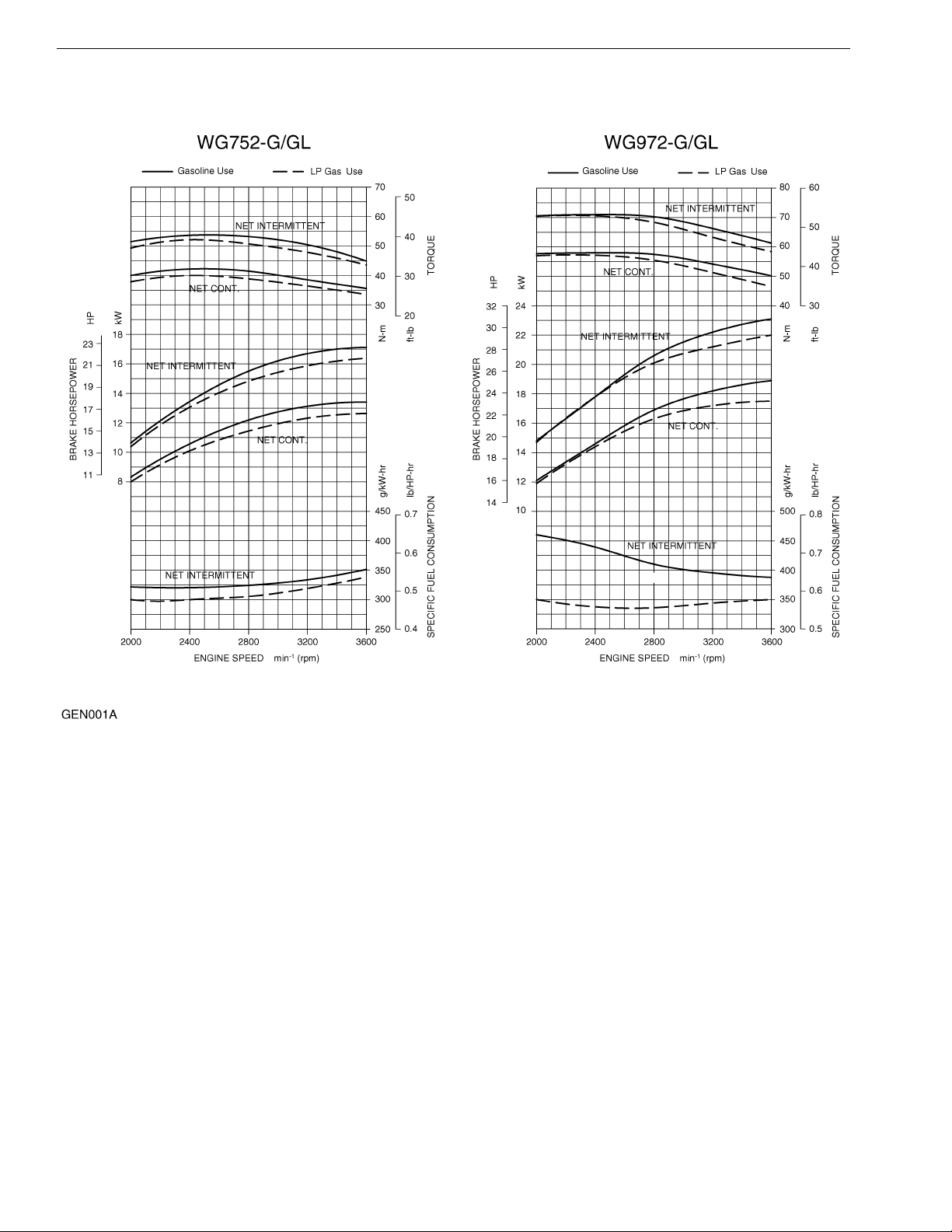
2. PERFORMANCE CURVES
0-4
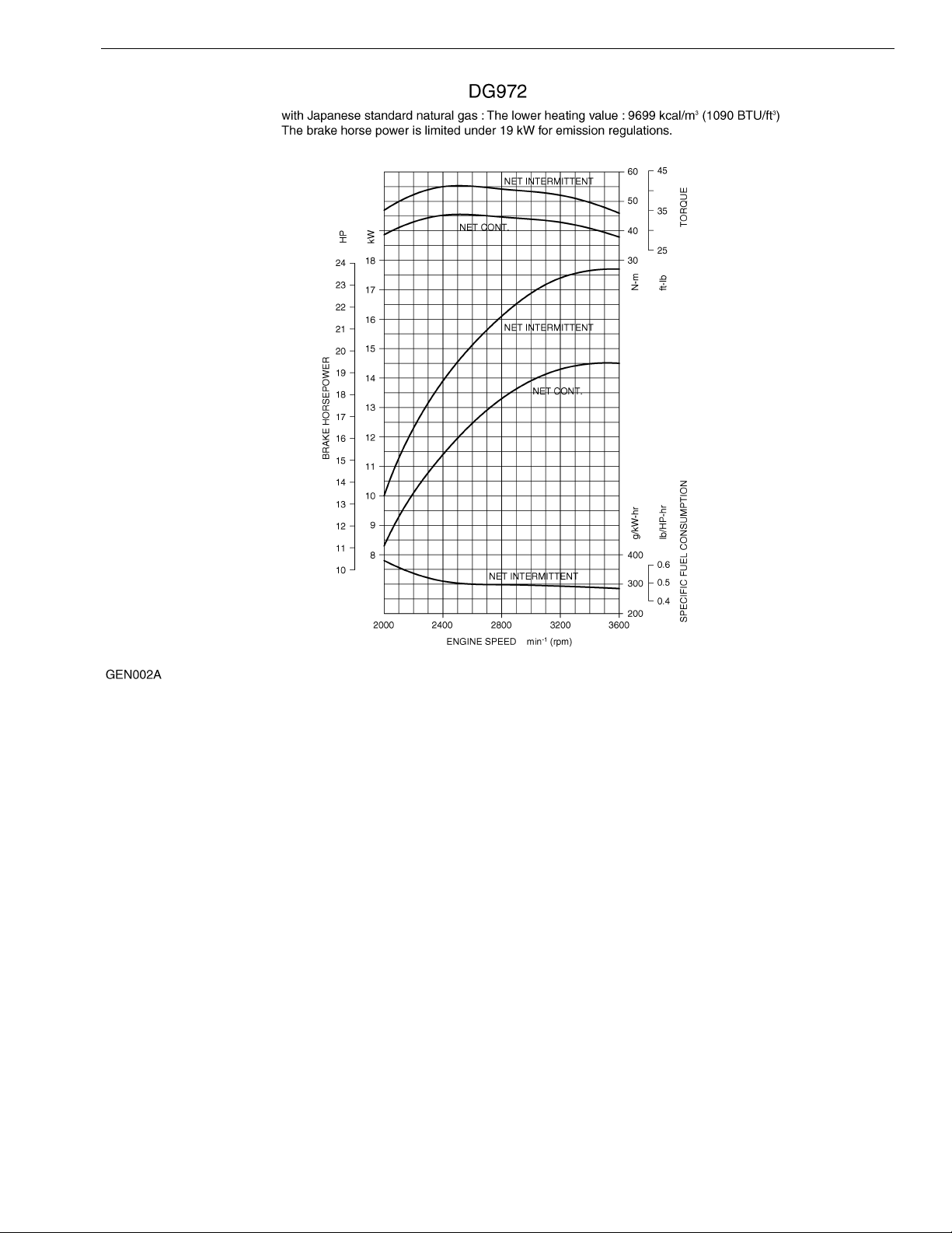
0-5
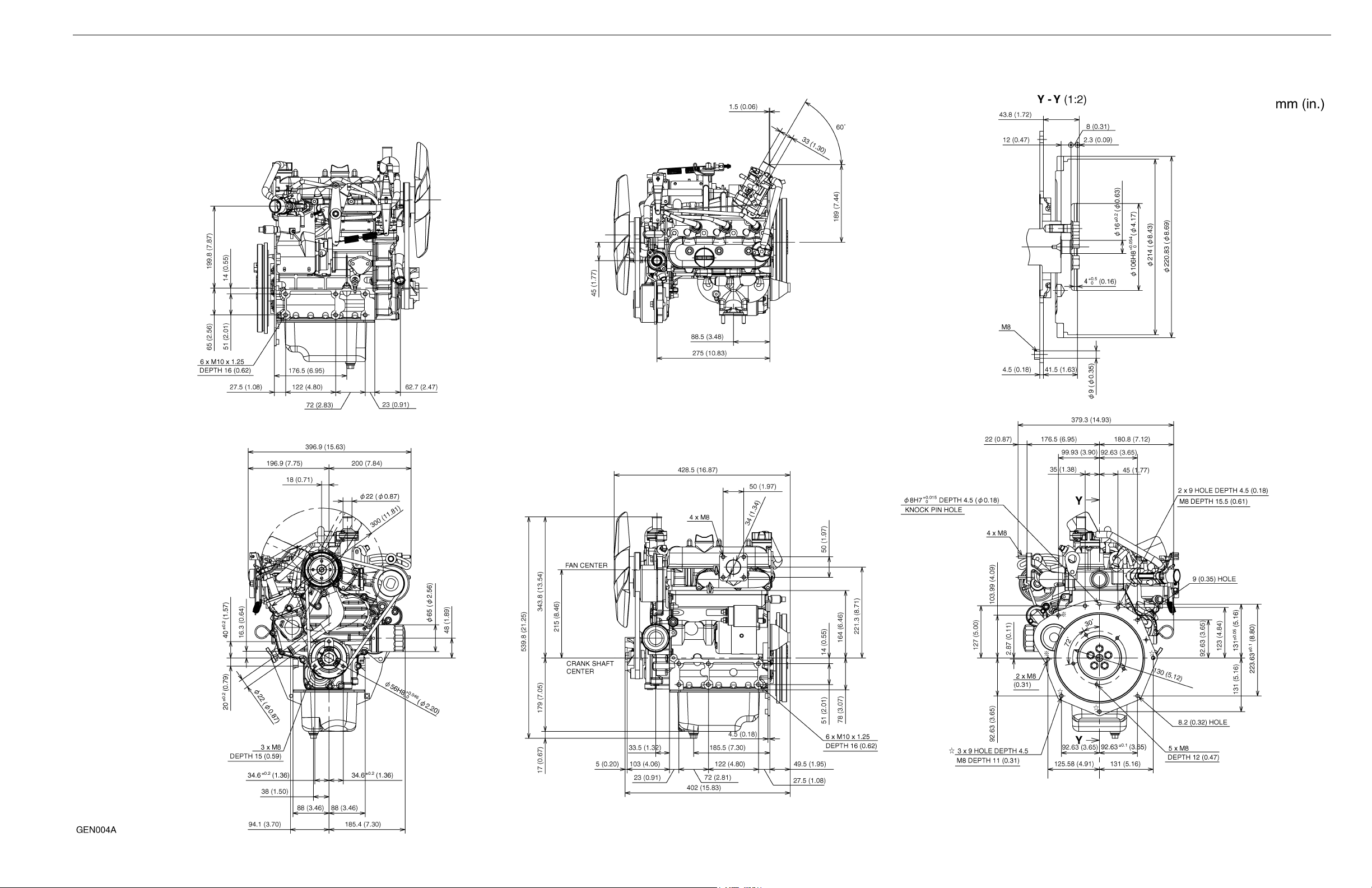
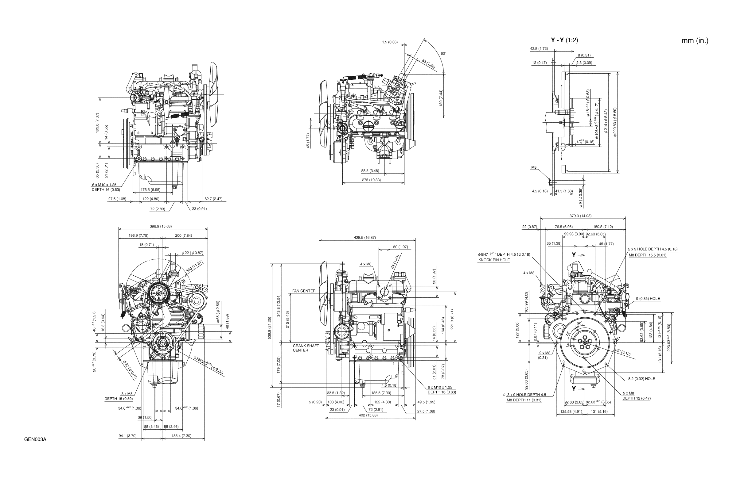
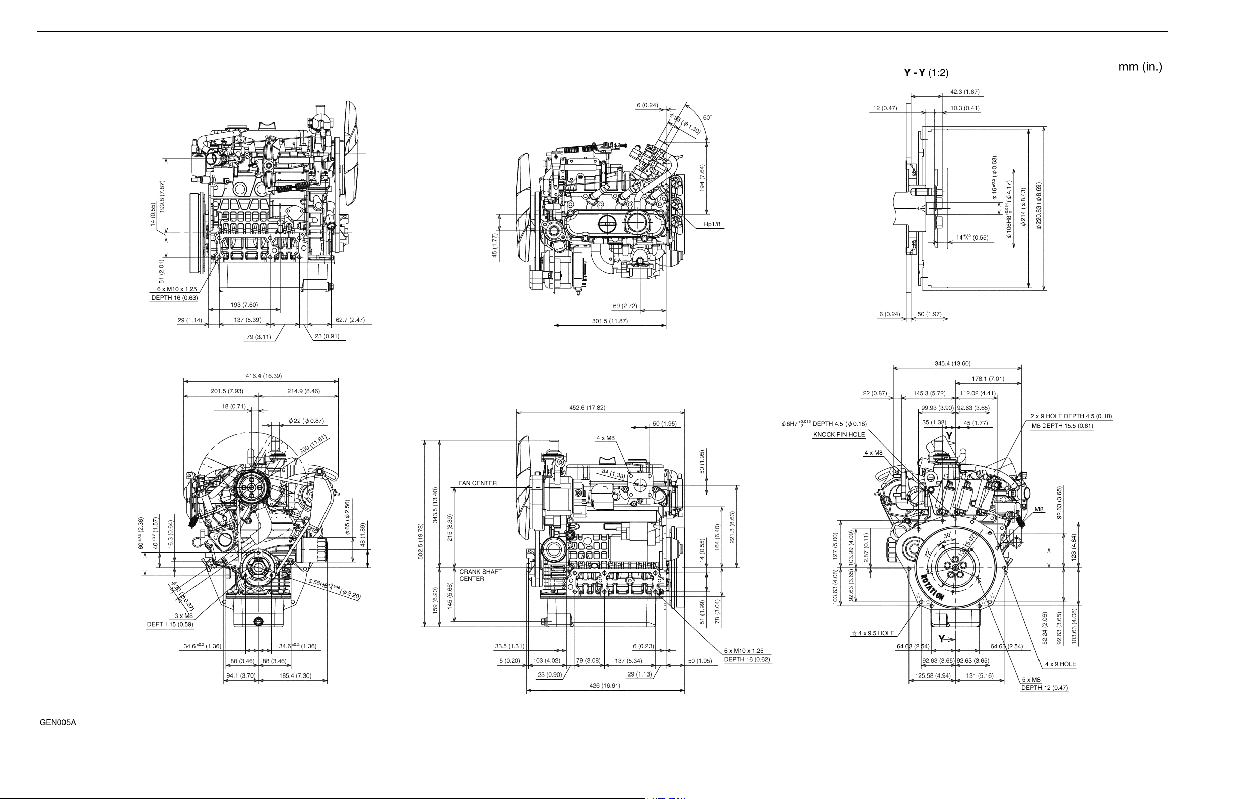
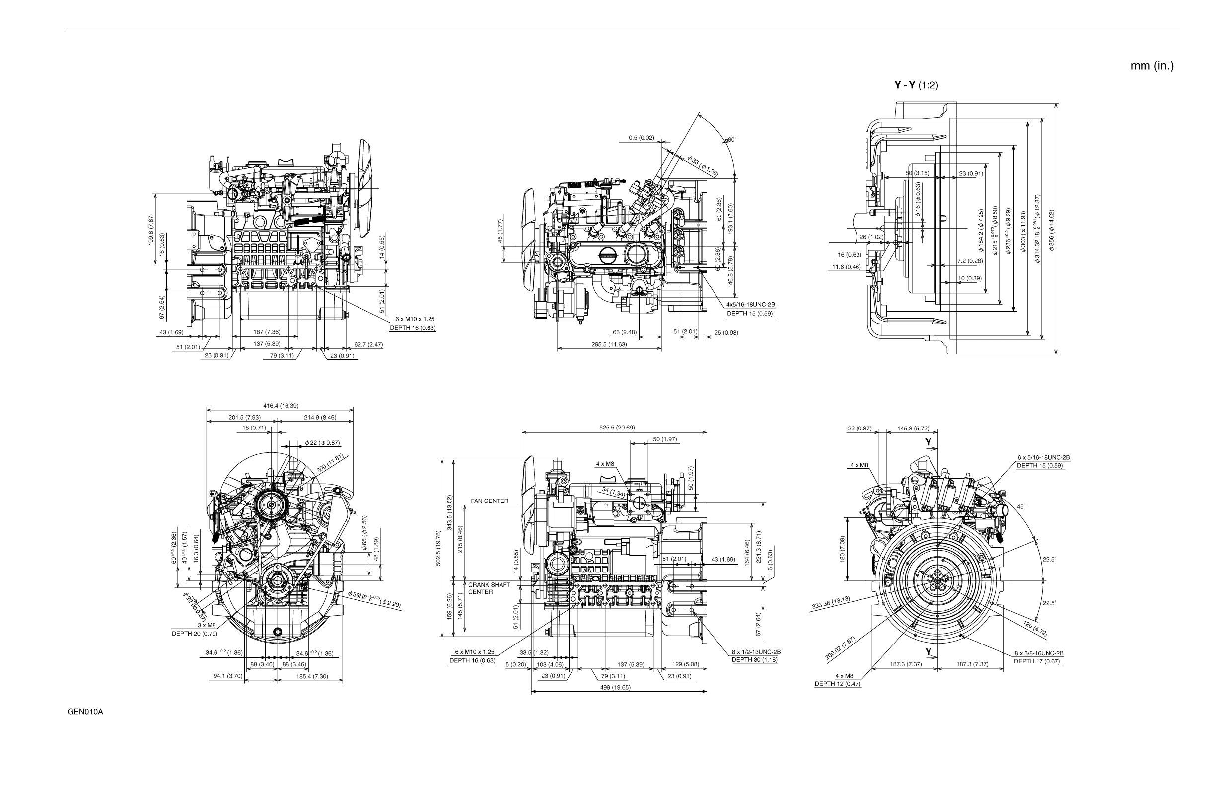
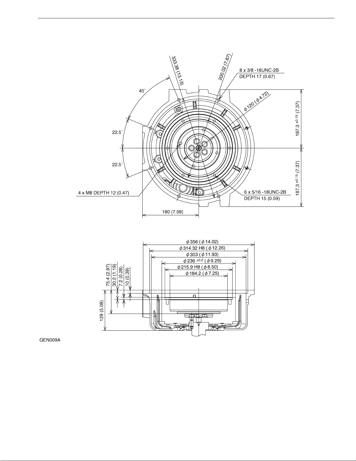
3. DIMENSIONS
WG752-G-E3BBH-1 (EG641-00000)
0-6
WG752-GL-E3BBH-1 (EG645-00000)
0-7
WG972-G-E3BBH-1 (EG801-00000)
0-8
WG972-GL-E3BBH-1(EG805-00000)
0-9
WG972-GL-E3SAEH-1 (EG802-00000)
0-10
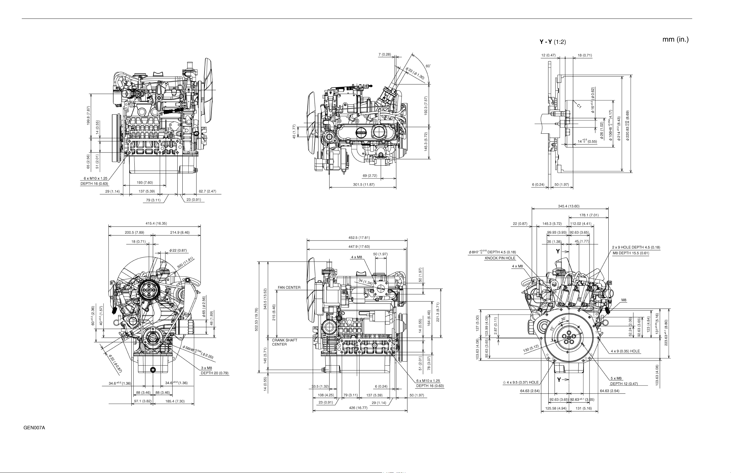
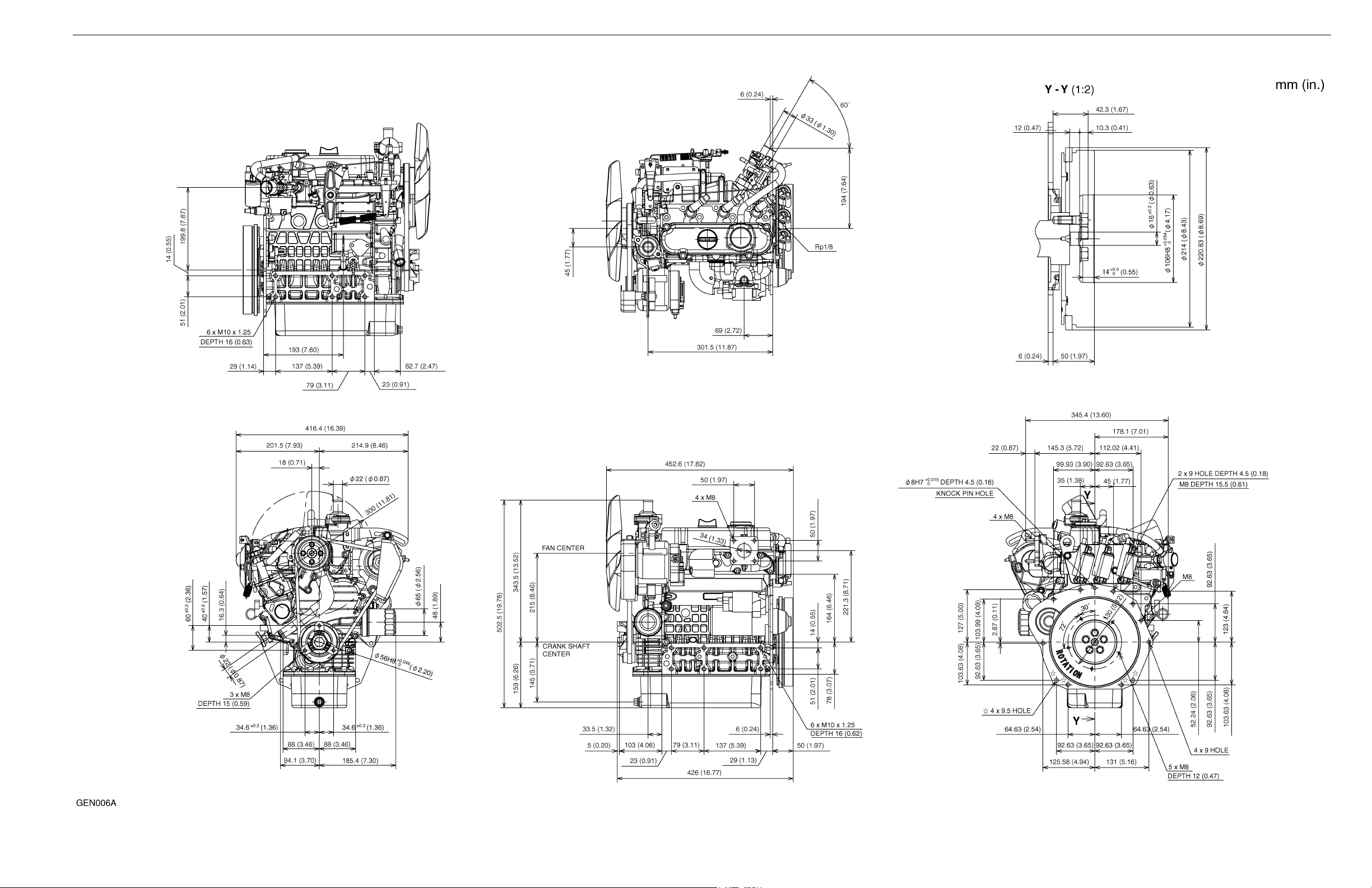
DG972-E2-BBH-1 (EG581-00000)
0-11
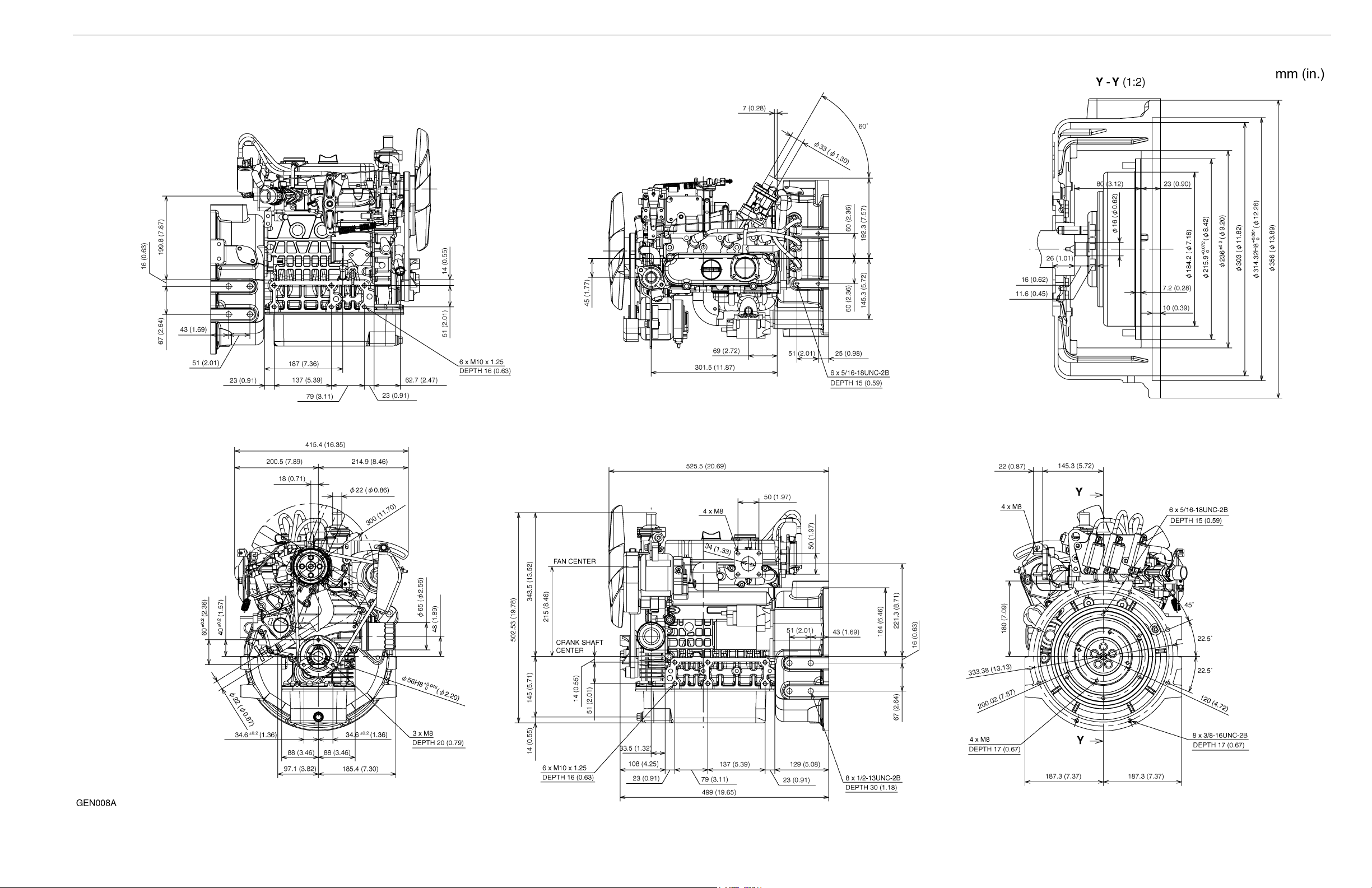
DG972-E2-SAEH-1 (EG582-00000)
0-12
WG752, WG972, DG972
Flywheel : Normal SAE for Clutch No.6-1/2
Flywheel Housing : Normal SAE No.5
0-13

1. EMISSION REGULATION
CONTENTS
1. GENERAL...................................................................................................................................... 1-1
2. IMPORTANT ITEMS...................................................................................................................... 1-2
[1] Important Notice ...................................................................................................................... 1-2
[2] Emission-Related Installation Instructions ............................................................................... 1-3
(1) Air Intake System .............................................................................................................. 1-3
(2) Exhaust System (See EXHAUST SYSTEM section) : (WG752, WG972)......................... 1-5
(3) High Altitude Operation (See FUEL SYSTEM section) : (WG752, WG972) ..................... 1-5
(4) Evaporative Emission Controls.......................................................................................... 1-5
(5) Engine Set Speed.............................................................................................................. 1-5
(6) Engine Labels.................................................................................................................... 1-6
(7) Vaporizer (WG752−GL, WG972−GL), Gas Regulator (DG972) Connections................... 1-6
(8) Tamper Resistance ........................................................................................................... 1-6
1. GENERAL
NOTE
NOTE
Along with E3 models, E2 models are yet available to be used in the following countries per output category.
kW, disp. Model Type North America Europe Japan
P ≤ 19
0.225 ≤ L
19 < P ≤ 30
0.825 < L ≤ 1.0
• * DG972 is only for stationary use.
e.g.oil field and emergency generator.
Current and future emission regulations.
Countries kW, disp. 2009 2010 2011 2012 2013 2014 2015 2016
CARB
USA
EPA
Canada
Japan
EU
WG752-G/GL-E3 E3 Available Non-available Available
WG/DF752-E2 E2 Non-available Available Available
DG972 * E2 Available Available Available
WG972-G/GL-E3 E3 Available Available Non-available
WG/DF972-E2 E2 Non-available Available Non-available
HC+NO
P ≤ 19
0.225 ≤ L
19 < P
L ≤ 0.825
19 < P
0.825 < L ≤ 1.0
P ≤ 19
0.225 ≤ L
19 < P ≤ 30
L ≤ 1.0
P ≤ 19
0.225 ≤ L
P < 19
0.225 ≤ L
19 ≤ P < 560 HC/0.6 g/kWh, NO
P ≤ 19
0.225 ≤ L
19 < P None
12.0/549 8.0/549 *
12.0/549 6.5/375 * 0.8/20.6 *
12.1/610 8.0/610 *
12.1/610 8.0/610 *
12.1/610 8.0/610
8.0/549 *
12.1/610
/0.6 g/kWh, CO/20 g/kWh
X
12.1/610
/CO (g/kWh)
X
• * with evaporative emission regulation
1-1

2. IMPORTANT ITEMS
[1] Important Notice
There are necessary emission-related items for compliance with emission regulations.
Please confirm whether emission-related items are certain on application review
(Exhaust Emission Check Sheet).
For mass-production Kubota prepares the installation instructions.
These instructions are provided for the final engine assemblers who must ensure the engine, exhaust system
(catalyst), intake system, gasoline fuel system and etc, are Installed correctly in the engine’s certified configuration.
(for EPA only)
Failing to follow these instructions when installing a certified engine in a piece of non-road equipment violates
federal law (40CFR 1068. 105(b)),subject to fines or other penalties as described in the Clean Air Act.
The contractual agreement contract is necessary before mass-production.
1-2
[2] Emission-Related Installation Instructions
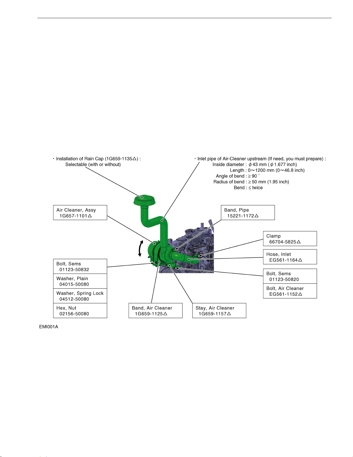
(1) Air Intake System
• Intake system means that layout of all parts from entrance of suction to air-cleaner flange.
• Kubota offers standard Air-cleaner kit. The intake parts should be installed as shown in figure below.
• If you use an OEM intake system for a spec engine, consult Kubota based on the Exhaust Emission Check Sheet
before the application review.
• When the same specification engine is installed on multiple applications, you will have to inform to Kubota prior
to the application review.
Also, the final intake system of each application must be confirmed at the application review and/or the Exhaust
Emission Check Sheet.
• You must install the intake system confirmed at the application review and/or the Exhaust Emission Check Sheet
for mass-production. (Important)
• You should consult Kubota based on the Exhaust Emission Check Sheet whenever you change the intake
system.
Do not change without consultation with Kubota.
WG752, WG972
1-3
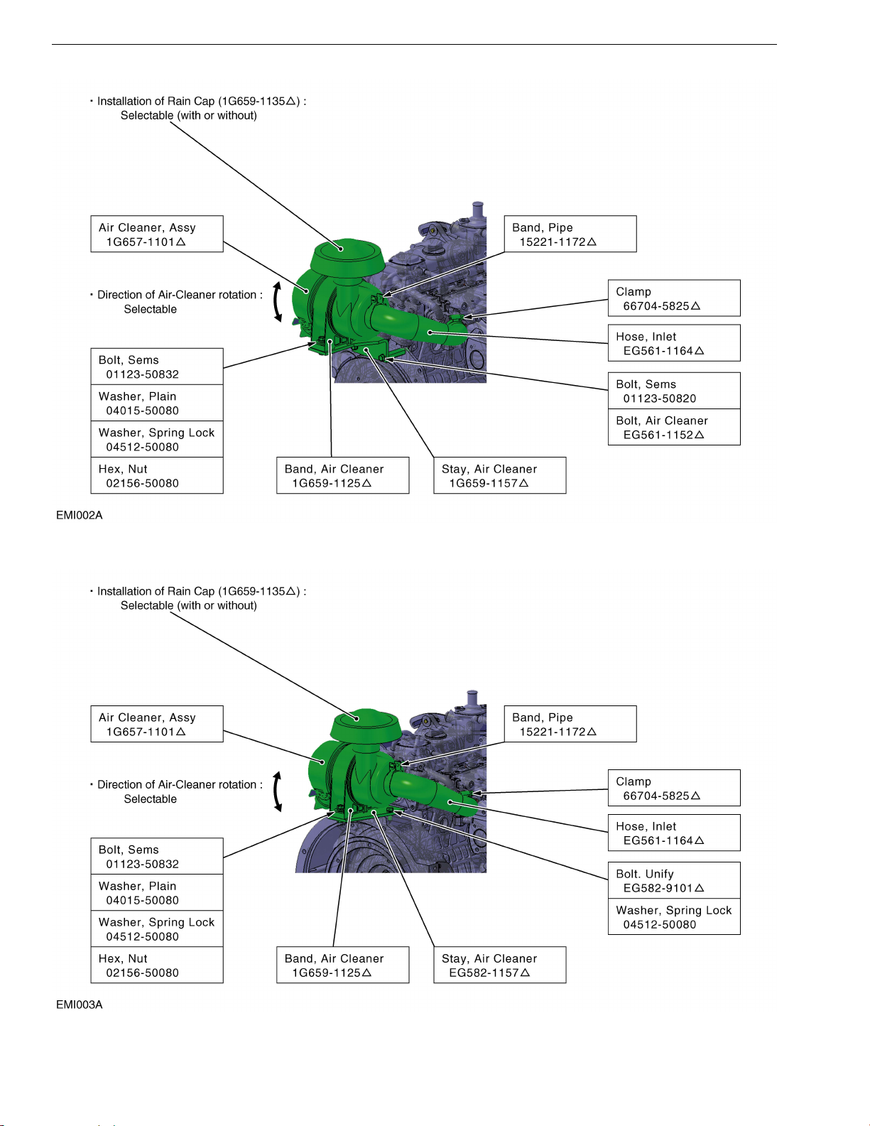
DG972-E2-BBH
DG972-E2-SAEH, WG-972-GL-E3SAEH
1-4
(2) Exhaust System (See EXHAUST SYSTEM section) : (WG752, WG972)
• Exhaust system means the layout of all parts from exhaust manifold to exhaust exit to atmosphere.
• Kubota offers certified catalytic mufflers and catalytic converters.
You must only use Kubota certified catalyst parts (Important) and assemble the exhaust parts according to
instructions as specified in the EXHAUST SYSTEM section of this manual.
Catalyst parts other than Kubota must not be used because other catalyst is not certified our engine.
You must install the exhaust system confirmed at application review and/or the Exhaust Emission Check Sheet
for mass-production. (Important)
• You must consult Kubota based on the Exhaust Emission Check Sheet when you change the exhaust parts after
application review. Do not change without the consultation with Kubota.
(3) High Altitude Operation (See FUEL SYSTEM section) : (WG752, WG972)
• Kubota prepared genuine altitude compensation kit.
The ultimate users must comply with the regulations through the installation of the appropriate altitude
compensation kit.
(4) Evaporative Emission Controls
(See EVAPORATIVE EMISSION CONTROL section) : gasoline fuel
• If your equipments use a volatile liquid fuel (such as gasoline), they must meet the evaporative emission
standards of 40 CFR part 1060,as described in §1054.112.
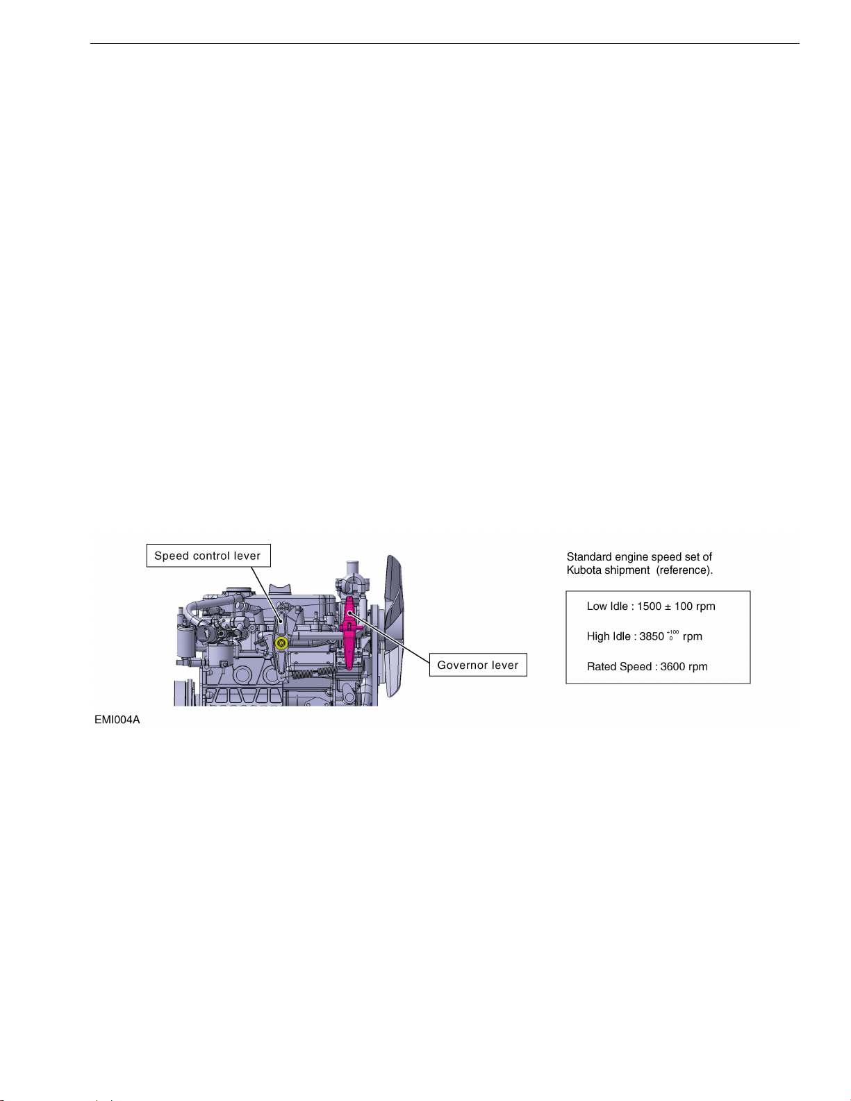
(5) Engine Set Speed
(Mechanical Governor specification)
• You should operate the engine within the range of engine speed set at the time of Kubota shipment
(without parasitic load).
• You should use the speed control lever and/or the governor lever when the speed change.
(Electronic Governor specification)
• If you use the electronic governor, consult Kubota before the application review.
1-5
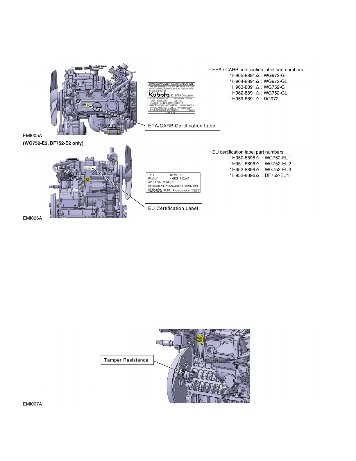
(6) Engine Labels
• The following labels must be visible. If you install the engine in a way that makes the engine’s emission control
information label hard to read during normal engine maintenance, you must place a duplicate label on the
equipment, as described in 40 CFR 1068.105.
(7) Vaporizer (WG752−GL, WG972−GL), Gas Regulator (DG972) Connections
(See FUEL SYSTEM section)
• The hose length between the vaporizer (gas regulator) and carburetor (gas mixer) must be within 300 ± 20 mm
(11.8 ± 0.78 inch). Only use hose appropriate for LPG.
(8) Tamper Resistance
• Any modifications to the tamper resistance parts on this engine will cause this engine to be in noncompliance with
emission regulations.
SENSOR (CRANK ANGLE) : (WG/DG972)
The ignition timing sensor also has a function of tamper resistant and the adjustment screw has been covered
after adjustment at the factory. You CAN NOT adjust the ignition timing.
1-6
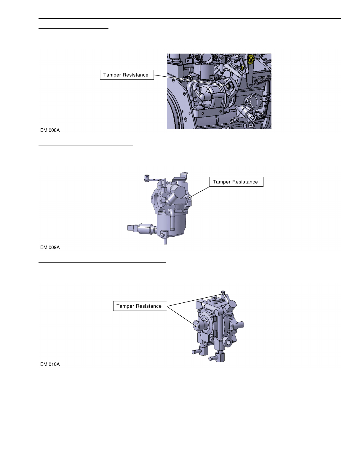
DISTRIBUTOR : (WG752)
The distributor is tamper resistant ; the ignition timing adjustment screw has been covered after adjustment at the
factory. You CAN NOT adjust the ignition timing.
CARBURETOR : (WG752, WG972)
The carburetor is tamper resistant ; the idle mixture screw has been covered by tamper plug after adjustment at
the factory. You CAN NOT adjust this screw.
LPG REGULATOR : (WG752
LPG regulator is tamper resistant ; the main and idle pressure adjustment screw have been covered by tamper
caps after adjustment at the factory. You CAN NOT adjust the screws.
−GL, WG972−GL)
1-7
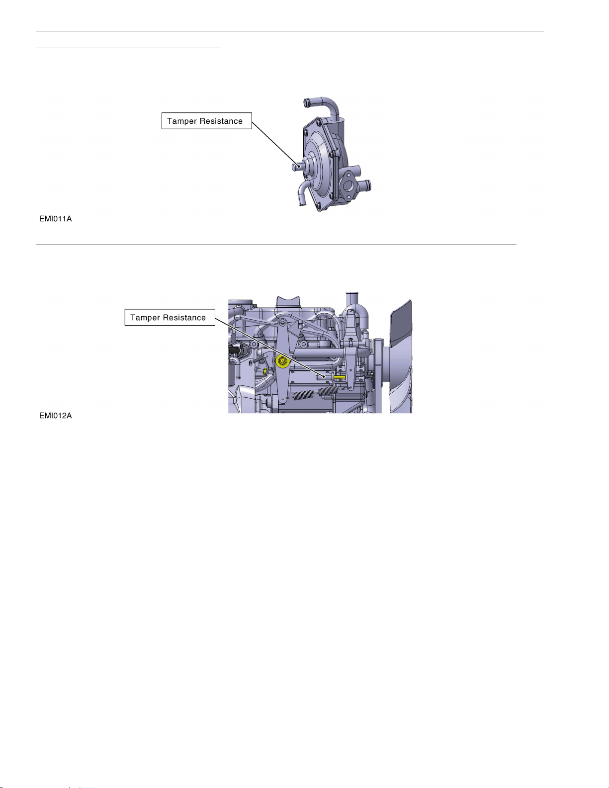
NATURAL GAS REGULATOR : (DG972)
Natural gas regulator is tamper resistant; idle pressure adjustment screws have been covered by tamper caps
after adjustment at the factory. You CANNOT adjust the screw.
GOVERNOR LEVER (THROTTLE ANGLE) : (Only spec model of specification that limits throttle angle)
The governor lever is tamper resistant; the governor lever adjustment screw has been covered after adjustment
at the factory. You CANNOT adjust the governor lever.
1-8

2. FUEL SYSTEM
CONTENTS
1. GENERAL...................................................................................................................................... 2-1
[1] Gasoline .................................................................................................................................. 2-1
[2] LPG ......................................................................................................................................... 2-1
[3] Natural gas .............................................................................................................................. 2-1
2. FUEL DIAGRAM............................................................................................................................ 2-2
3. CAUTIONS .................................................................................................................................... 2-4
[1] For safety (WG752−GL, WG972−GL, DG972)........................................................................ 2-4
(1) Tightening torque and leak check for vaporizer and gas regulator.................................... 2-4
(2) Change the angle of LPG fitting of dual fuel carburetor and Gas fitting of gas mixer........ 2-4
(3) Setting and vibration limits.................................................................................................2-4
(4) Starting the engine (WG752−GL, WG972−GL)................................................................. 2-4
[2] For emission regulations (WG752−GL, WG972−GL, DG972) ................................................ 2-5
(1) Vaporizer and Gas regulator ............................................................................................. 2-5
(2) Length of the gas hose ...................................................................................................... 2-5
4. HIGH ALTITUDE OPERATION (WG752, WG972) ....................................................................... 2-6
5. EVAPORATIVE EMISSION CONTROL (gasoline fuel)................................................................. 2-7
[1] Regulations.............................................................................................................................. 2-7
[2] Related Check Items ............................................................................................................... 2-7
 Loading...