

Kubota D1803-CR-TIE4B-KEA-2, D1803-CR-TIE4B-KEA-1, D1803-CR-TIE4BG-KEA-1, V2403-CR-TIE4B-KEA-1, V2403-CR-TIE4B-KEA-2 Installation Instructions Manual
...Page 1
K
ubota
Installation Instructions
CAR
B/EPA certified Tier
4f engines:
D1803-CR-TIE4B-KEA-1 (1J497-10000)
D
1803-CR-T
D
1803-CR-T
V2403-CR-T
V2403-CR-T
V2403-CR-T
IE4B-KEA-2 (1J497-20000
IE4BG-KEA-1 (1J478-10000
IE4B-KEA-1 (1J498-10000
IE4B-KEA-2 (1J498-20000
IE4BG-KEA-1 (1J488-10000
Append
ix 5
)
)
)
)
)
T
he instructions in this document supersede any other previous instructions provided by Kubota.
Kubota Emissi
Document Number : KEA-S
on-R
elated Installation Instructions
TD-03-CRS-DOC-
001
-
④
Page No
.
1
Page 2
Contents
Append
ix 5
Important Notice
Objectiv
1. Ex
e Items
haust System ------------------------------------------------------------
----------------------------------------------------------------
-----------------------------------------------------------------
2. Intake System ---------------------------------------------------------------
3.Fuel System -----------------------------------------------------------------
4.Engine Control Unit (E
5. Engine Control System (Wire Harness
6.Certification Labels
7.App
licati
on Review Requirement
8. Installation Instructions Re
CU) ----------------------------------------------
/
Display P
ane
l)----------
-------------------------------------------------------
s--------------------------------------
visi
on Log
----------------------------------
page 3
page 4-5
page 6-15
page 16-36
page 37-43
page 44-57
page 48-50
page 51
page 52
page 53
Kubota Emissi
Document Number : KEA-S
on-R
elated Installation Instructions
TD-03-CRS-DOC-
001
-
④
Page No
.
2
Page 3
Append
ix 5
Important Not
ice
EMISSION-RELATED INSTALLATION INSTRUCTIONS
These instructions ar
the engine, exhaust
sensor), engine control system etc, are installed correctly in the engine’s certifi
c
onfiguration. The e
tail pipe or
wir
e harness and contro
useful life of the component without any failure.
Faili
ng to follow these instructions when insta
piece of nonroad equipment violates federal law (40
and is subject to fines or other penalties as de
e provided for the final engine assemblers (FEA) who must ensure
system (After Treatment De
missi
on related parts which FEA pr
ls) mus
t be designed to function throughout the
vic
e: ATD), i
lli
scri
ntake
system (Air flow
epare (for example the exhaust
ng a certified engine in a
CFR
1068.105(b)),
bed in the Clean Air Act.
ed
Kubota Emissi
Document Number : KEA-S
on-R
elated Installation Instructions
TD-03-CRS-DOC-
001
-
④
Page No
.
3
Page 4

1. Exhaust Syste
K
ubota supplies a certified diesel oxidation cata
m
treatment and assemble the exhaust
for use with these
KEA s
tandard engine models. Therefore, no other exhaust after treatment can be used.
Objective Items
lyst (DOC) assembly. FEA must use the Kubota supplied certified exhaust after
system
parts according to the instructions. No other exhaust after treatment is certified
Append
ix 5
2. Intake Syste
These Tier
m
4 common rail engines ut
iliz
e a mass air flow (MAF) sensor to control the EGR flow rate. The air cleaner location
and piping layout must be installed according to these installation instructions to maintain proper performance of the MAF
sensor
output. Als
resis
tance and charge air cooler performance must be kept within certain
3. Fuel Syste
m
In order to maintain the common rail fuel injection pump performance and durab
mus
t be checked during the app
o, to prevent decreases of engine output performance and to maintain e
criteri
a.
ility
the pressure and temperature of the fuel
licati
on review.
missi
on compliance, intake
4. Engine Control System (Engine Control Unit (ECU)
T
he Engine Control Unit (E
correctly
within K
and that the requirements and specifications are checked during the app
ubota specification. Othe
5. Engine Control System (Engine Control Unit (ECU), Wire Harness, Operator Display Panel
T
he
wir
e harness is also considered an e
correctly
and that the requirements and specifications are checked during the app
be within Kubota specification. Othe
CU) is consider
rwis
e, engine and e
rwis
e, engine and e
ed an e
missi
on control de
missi
missi
on control de
missi
Kubota Emissi
Document Number : KEA-S
vic
e. It is
critical
to ensure that the ECU is install
licati
on review. The elect
on performance cannot be guaranteed.
)
vic
e. It is
critical
to ensure that the
wir
licati
on review. The elect
on performance cannot be guaranteed.
on-R
elated Installation Instructions
TD-03-CRS-DOC-
001
-
④
rical si
e harness is installed
rical si
ed
gnal must be
gnals must
Page No
.
4
Page 5
Objective Items
Append
ix 5
6. Certif
7.
ication Labels
K
ubota insta
lls
the certification label on the
cyli
nder head cover. If the final engine assembler insta
makes the engine’s emission control information label hard to read during normal
assembler must place a dup
App
lication Review Requirements
Distri
butor is responsible for completing full app
lic
ate label on the equipment, as de
licati
on review for standard engine to ensure quality engine installation. The
scri
bed in 40
lls
the engine in a way that
engine maintenance, the final engine
CFR
1068.105.
application review should be completed according to Kubota’s application review standards and application manual
r
equirements.
Kubota Emissi
Document Number : KEA-S
on-R
elated Installation Instructions
TD-03-CRS-DOC-
001
-
④
Page No
.
5
Page 6
Append
ix 5
1-1. Ex
1-1-1. Ex
haust System S
haust System S
Exhaust
A
system m
n example of exhaust
upp
1. Exhaust System
ly
upply for
eans the layout of all parts from the exhaust manifold to the exhaust exit.
KEA S
tandard CRS-DOC Engines
system is show
N
o.1 : Diesel Oxi
n below.
dation Cata
lyst (DOC)
N
o.4 : Tail Pi
N
o.3 : Bolt
N
o.2 : Gasket
pe
Kubota Emissi
Document Number : KEA-S
on-R
elated Installation Instructions
TD-03-CRS-DOC-
001
-
④
Page No
.
6
Page 7
supplied
1J497- 1810△ 1 D1803- CR- TIE4 Engine Code: 1J497- 10000 , 1J478- 10000
1J807- 1810△ 1 D1803- CR- TIE4 Engine Code: 1J497- 20000
1J808- 1810△ 1 V2403- CR- TIE4 All V2403- CR- TIE4 Models
M8 x 1.25mm ISO 8.8
Meet t he back pressure and flange requirements.
1. Exhaust System
K
ubota supplies the following parts as shown below, these parts must be used in the exhaust
FEA supplied parts must meet the installation instruction requirements.
system
Append
ix 5
.
No. Part Name FEA
Diesel Oxidation Catalyst1
2 Gasket
3 Bolt
4 Tail Pipe
N
ote: Part numbers / assemblies for item #1, Diesel Oxi
○
○
Kubota
○
○
KBT Part No. Q'ty Engine Model Remarks
Qty: 1 Gasket supplied with engine.
17326- 1223△ 1 All 03 Series
Qty: 3 Gaskets are required for remote DOC installation.
(See page 12- 13 f or remote DOC installation details)
- 4
- -
dation Cata
Kubota Emissi
Document Number : KEA-S
lys
t, vary based on the base engine.
on-R
elated Installation Instructions
TD-03-CRS-DOC-
001
-
④
Page No
.
7
Page 8
1-2. Ex
haust System
Layout
DOC (Diesel Oxidation Cata
Incorrect DOC inst
allation will cause emission
1-2-1. DOC Installation Options:
A
. Standard DOC Installation Position: T
K
ubota production fa
cility as
the standard configuration. Kubota recommends to keep the DOC in this
factory location.
B. DOC Outlet
C. Remote
It is
critical
Angle: C
Mount DOC: Certai
hanging the DOC outlet angle is acceptable. See following pages.
n app
to follow the instructions outlined in this installation manual to guarantee e
1. Exhaust System
lyst)
Installation for
he DOC is installed onto the top side of the f
lications will r
KEA CRS-DOC S
non-comp
equire for the DOC to be relocated.See following pages.
tandard Engines
liance and/or damage to the DOC
lyw
heel housing at the
missi
on compliance.
Append
ix 5
.
DOC (Diesel Oxidation Cata
Factory
Document Number : KEA-S
Location
Kubota Emissi
lyst)
on-R
elated Installation Instructions
TD-03-CRS-DOC-
001
-
④
Page No
.
8
Page 9
Industrial
Industrial
BG
Industrial
Industrial
BG
1. Exhaust System
Append
ix 5
1-2-1.A Factory Mounted Installation Position (DOC): Ex
Back pressur
Measurem
Engine Model 10 Digit Code Maximum Back Pressure Remarks
D1803- CR- TIE4B- KEA- 1 1J497- 10000 50 mm Hg
D1803- CR- TIE4B- KEA- 2 1J497- 20000 50 mm Hg
D1803- CR- TIE4BG- KEA- 1 1J478- 10000 40 mm Hg
V2403- CR- TIE4B- KEA- 1 1J498- 10000 50 mm Hg
V2403- CR- TIE4B- KEA- 2 1J498- 20000 50 mm Hg
V2403- CR- TIE4BG- KEA- 1 1J488- 10000 40 mm Hg
e of exhaust tail pipe at full load, rated speed condition must be according to table below.
ent point of back pressure of exhaust
system is within 1” (25.4 mm) of the DOC outlet.
Back Pressure Measurement
Location
haust Back Pressure Check
Kubota Emissi
Document Number : KEA-S
on-R
elated Installation Instructions
TD-03-CRS-DOC-
001
-
④
Page No
.
9
Page 10
1. Exhaust System
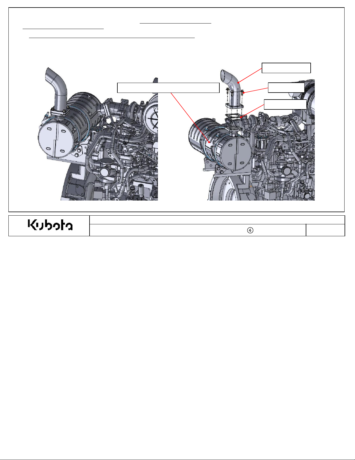
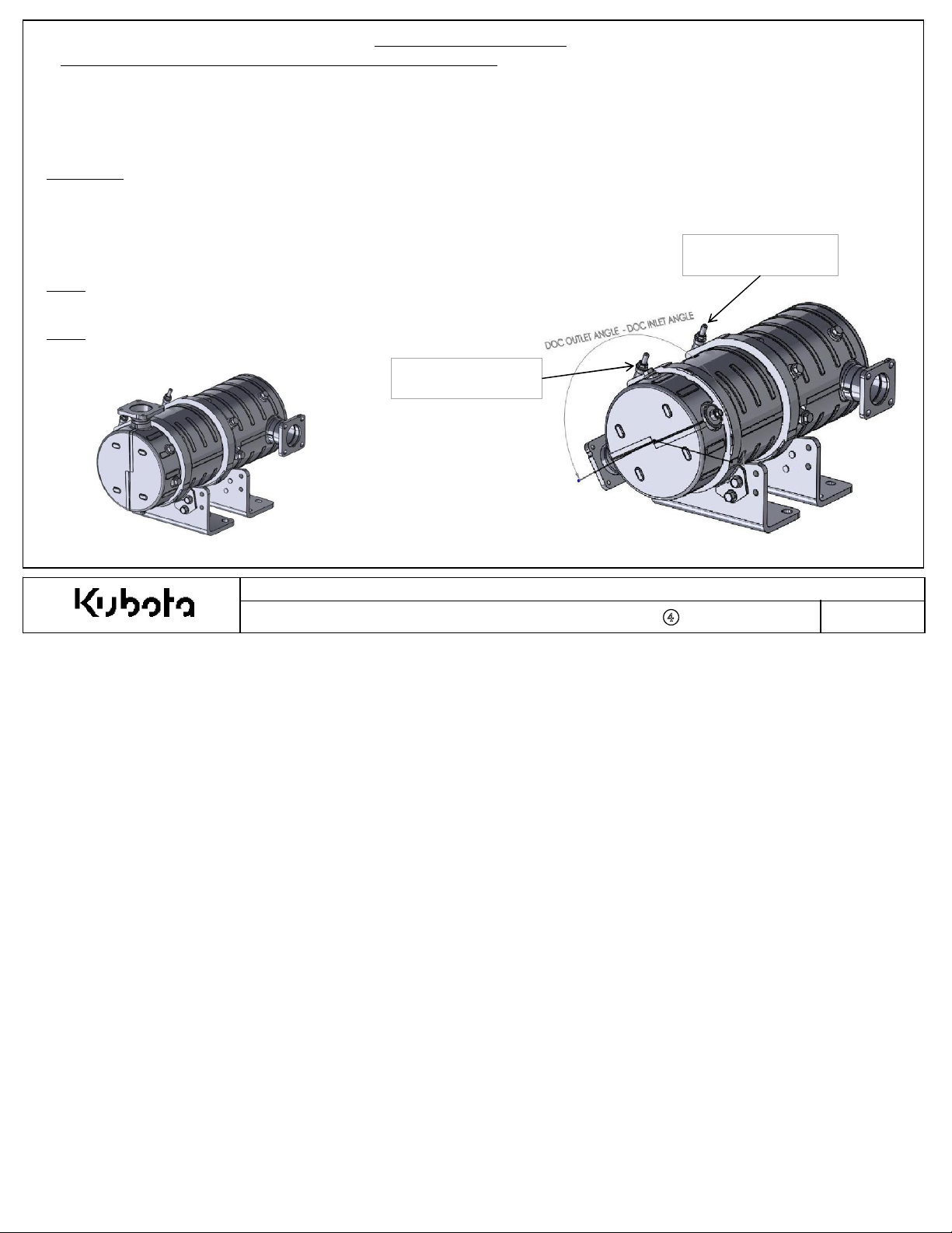
1-2-1.B DOC Outlet Angle Adjustment Proc
1.Kubota recommends to keep the DOC outlet angle in the standard position, but certain app
2.Adjusting the DOC outlet angle is acceptable to meet the installation requirements of the machine.
•Installati
•Angle adjustment must be completed only 1 time (to min
•Angle adjustment must be completed before customers run the engine(to min
on instructions must be carefu
lly
followed to ensure e
edure (Option)
missi
imize risk
of clamp breakage).
on compliance.
imize risk
lications will r
of clamp deterioration due to heat).
equire adjustment.
Append
ix 5
Procedure
STEP
STEP
STEP
STEP
STEP
N
ote 1: It is NOT allowed to adjust the DOC inlet portion of the DOC.
Only
N
ote 2: Any exhaust gas leakage or failures due to incorrect modification is not
cover
:
1: Loosen DOC band clamp at DOC outlet position and remove DOC outlet portion.
2: Replace gasket with new parts. Refer to
3: Ori
ent the DOC outlet to the de
4: Tighten Band clamp nut to 16-20 Nm.
5: Start engine and conf
the DOC outlet position can be adjusted.
ed under standard/e
irm
missions warr
sir
that there are no exhaust leaks.
anty.
STANDARD DOC CONFIGURATIO
ed angle
illustr
ated parts
(similar
lis
to image to the right).
Loosen This DOC
B
and Clamp
N
Kubota Emissi
Document Number : KEA-S
t for gasket P/N.
A
DJUSTED DOC OUTLET ANGLE
on-R
elated Installation Instructions
TD-03-CRS-DOC-
001
-
④
Do NOT
DOC B
Loosen This
and Clamp
Page No
.
10
Page 11
1. Exhaust System
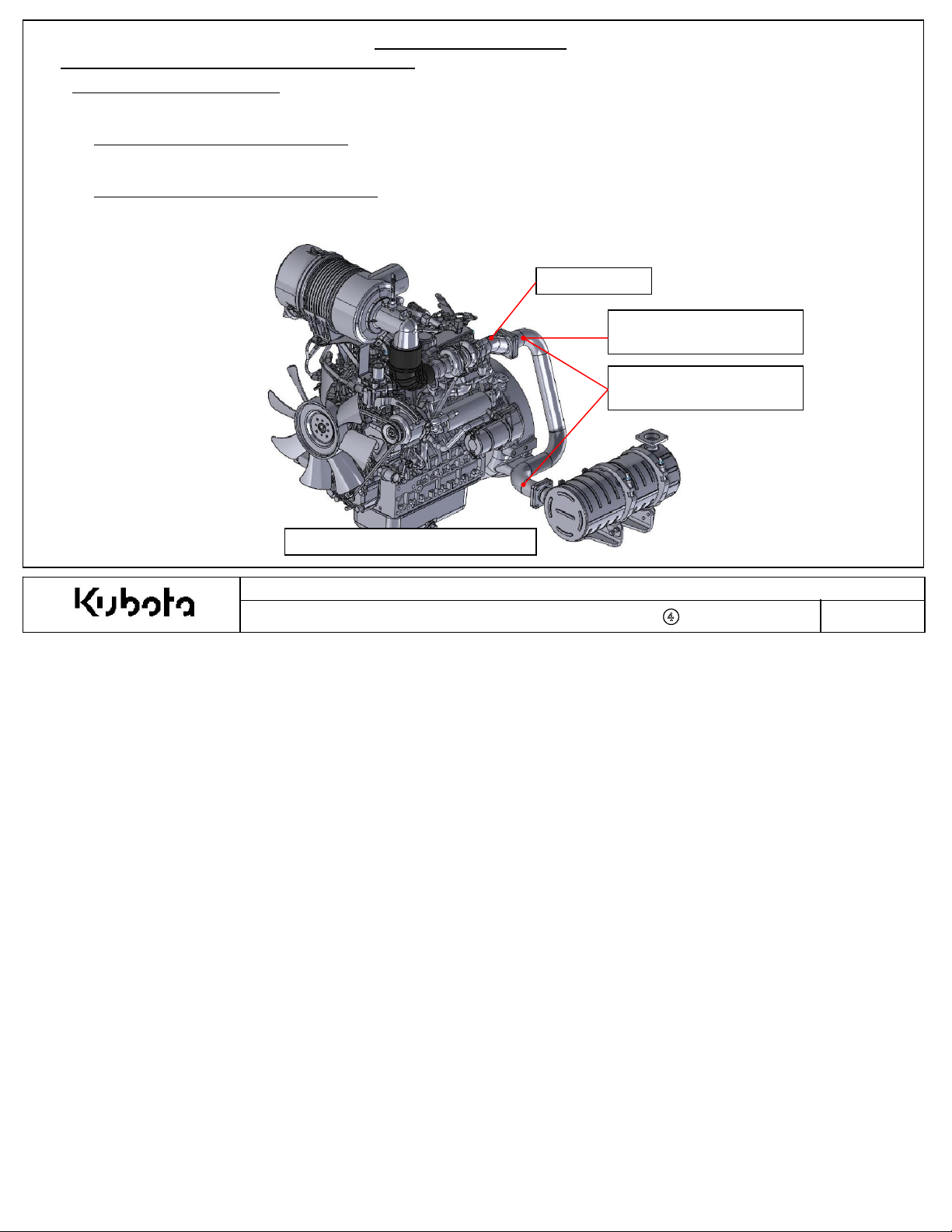
1-2-1.C Remote Mounting the DOC (Option)
Rem
ote DOC Installation Option
Certai
n app
lications will r
equire for the DOC to be relocated.See below installation
criteri
Append
ix 5
a.
1.Exhaust Backpr
A.T
outlet must be less than 113
essure Requirement:
he ma
ximum allowabl
e exhaust back pressure for the complete exhaust
mmH
2.Exhaust Temperature Drop Requireme
A. T
he ma
ximum allowabl
r
ated speed full load condition. Ex
e temperature drop across the intermediate exhaust pipe must be less than 25 deg. C at the
EXAMPLE REMOTE MO
system measur
ed at the muffler flange
g. The back pressure must be measured at the rated speed full load condition.
nt:
haust pipe insulation may be required and is recommended to meet this requirement.
M
uffler Flange
Measurem
Exhaust Back Pressur
Measurem
ent Location for
e
ent Location for
Exhaust Temperature (∆T)
UNT DOC
Kubota Emissi
on-R
elated Installation Instructions
Document Number : KEA-S
TD-03-CRS-DOC-
001
-
④
Page No
.
11
Page 12
1. Exhaust System
1-2-1.C Remote Mounting the DOC (Option)
Remote DOC Installation Option Continued…
Append
ix 5
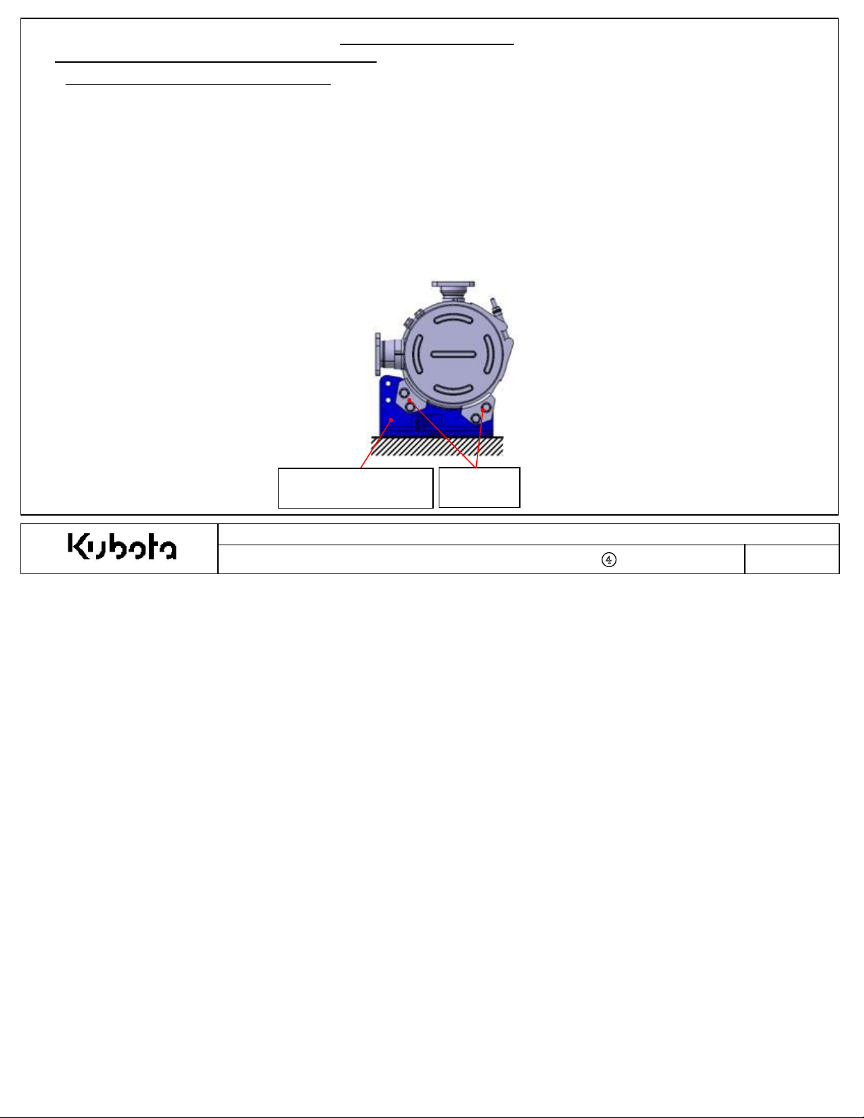
3. Other Inst
A
. Intermediate pipe for remote DOC (from turbo-out to DO
B.T
he muffler flange must not be removed from the engine. The intermediate exhaust pipe must connect to the outlet of the
m
uffler flange.
C.T
he intermediate exhaust pipe and flexible coupling must not leak exhaust gases during operation.
D.New m
remov
E.Ti
ghtening torque for the muffler flange outlet and DOC inlet M8 fasteners is 24-27
F.Reloc
G
. It is strongly recommended to use the Kubota supplied DOC mounting brackets (shown below in blue).
H.DOC incli
allation Requirements for Remotely Installed DOC
C-inlet) must incl
ude a flexible portion.
uffler flange outlet gasket, DOC inlet gasket, studs, and nuts on muffler flange outlet are required when DOC is
ed from engine for remote installation. Refer to the
ated DOC needs to be mounted without exce
illustr
ssive strain/l
ated parts
oad on V-
lis
t for the correct replacement part numbers.
N·m
.
band clamps.
nation angle must follow the required installation angles defined in the next page.
K
ubota Supplied DOC
M
ounting Brackets
V-band
Clamps
Kubota Emissi
Document Number : KEA-S
on-R
elated Installation Instructions
TD-03-CRS-DOC-
001
-
④
Page No
.
12
Page 13
Append
ix 5
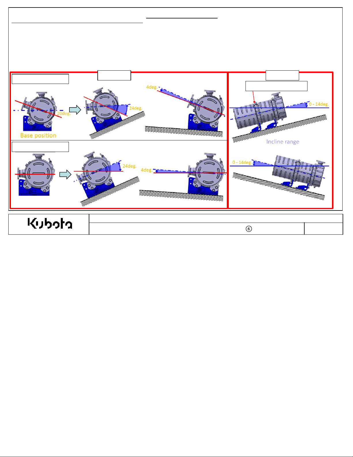
1-2-1.C Remote Mounting the DOC (Option)
4. Other Inst
A.DOC incli
B.T
C.T
D
1803
V
2403
he DOC inlet band clamp cannot be loosened or modified in any way.
he DOC can only be in
-CR-TIE4B-***
-CR-TIE4B-***
allation Requirements for Remotely Installed DOC
nation angle must be installed according to the angles defined below.
cli
ned according to option #1 or option #2, not the combination.
I.Option #1: Rotate the DOC about the DOC cente
i.Please note the required installation angle
II.Option #2: In
cli
ne the DOC up to +/-14 deg.
Option #1
1. Exhaust System
rli
ne a
xis
.
limits
below
(view
ed from DOC inlet side
Option #2
DOC
Inlet Band Clamp
)
Base position
Kubota Emissi
Document Number : KEA-S
on-R
elated Installation Instructions
TD-03-CRS-DOC-
001
-
④
Page No
.
13
Page 14
1. Exhaust System
Append
ix 5
1-3 DOC
(Diesel Oxidation Cata
lyst)
Installation
Criteria {Applies for engine mounted or remote mounted DOC}
1.DOC vibration:
-Accelerati
-Vibrati
on/
Displacem
ent must not exceed the
on must be checked during the app
licati
limits prescri
on review.
bed in the app
licati
on review form.
2. The DOC shall not support mounting loads from adjacent or mated components (tail pipe/intermediate pipe):
- Check DOC
tail pipe vibration during app
licati
on review to ensure it
will
not damage the DOC during long term operation.
-
Intermediate exhaust pipe for remote mount DOC may require support brackets.
3. Pleas
4. OEM Tail Pi
e note that the DOC
- Check surr
ounding component temperatures during the app
pe Requirements:
ski
n temperature can reach about 250
° C
licati
:
on review.
- FEA supplied bolts:
- Fl
ange bolts: M8 x 1.25, strength cla
- Ti
ghtening torque; 24-27
N·m
ssificati
on is ISO
8.8
- Tail Pipe Flange:
- Fl
ange th
- Fl
atness of the flange face is ma
ickness is 8mm or mor
e.
ximum
0.1mm.
-Surface finish of the flange face is 3.2Ra.
5. Intermediate Ex
-Accelerati
app
-Vibrati
haust Pi
licati
on review form.
on/
Displacem
pe Vibrati
on: for remote mounted DO
ent must not exceed the
on must be checked during the app
licati
C
limits prescri
on review.
bed in the
Kubota Emissi
Document Number : KEA-S
on-R
elated Installation Instructions
TD-03-CRS-DOC-
001
-
④
Page No
.
14
Page 15

1-4. Other Notice
1. Exhaust System
Append
ix 5
1. The exhaust
etc. around the exhaust
system will
be very hot, so to protect elect
system
and for the safety of operators, FEA s
rical
parts such as the starter, the alternator, fuel
hould install heat shields or insulating blankets as
system
necessary. It is acceptable to wrap the DOC if necessary. However, heat shield must not be welded to the DOC.The
temperature of these surrounding components must be conf
pre
scri
bed
2. Conf
limits shown i
irm
that water does not enter the exhaust
po
ssibl
e, install a rain cover or
n the app
similar
licati
on review form.
system from
de
vic
e.
irm
ed during the app
licati
on review and must be within the
the tail pipe outlet in all operating conditions. If water entry is
Kubota Emissi
on-R
elated Installation Instructions
parts,
wiri
ng,
Document Number : KEA-S
TD-03-CRS-DOC-
001
-
④
Page No
.
15
Page 16

Append
ix 5
2-1. Intake System Scope of Supply for
Intake
system m
A
n example of an intake
N
o.1 : Air Cl
N
o.2 : Mass Air Flow Sensor
eans the layout of all parts from the air inlet / pre
system wi
th the
eaner Assembly
2. Int
KEA S
KEA S
tandard CRS-DOC engine is shown below.
N
o.7 : Rain Cap / Pre-cl
ake System
tandard CRS-DOC Engines
-cl
eaner hose to the intake manifold or turbo charger.
eane
N
o.6 : Pre-Cl
N
o.4 : Air
Inlet Hose
r
eaner Hose
N
o.3 : Air Cl
eaner Band Clamp
N
o.5 : Air Cl
eaner Brack
Document Number : KEA-S
et
Kubota Emissi
on-R
elated Installation Instructions
TD-03-CRS-DOC-
001
-
④
Page No
.
16
Page 17

supplied
1J497- 1101△ 1 7" Non- Rotatable A/ C (S/ N: <7HU* * ** )
1E690- 1101△ 1 7" Rotatable A/ C (S/ N: >7HU* ** * )
1J497- 1101△ 1 7" Non- Rotatable A/ C (S/ N: <7HU* * ** )
1E690- 1101△ 1 7" Rotatable A/ C (S/ N: >7HU* ** * )
7" Non- Rotatable A/ C (All S/ N's)
1J498- 1101△ 1 8" Non- Rotatable A/ C (S/ N: <7HU* * ** )
1E691- 1101△ 1 8" Rotatable A/ C (S/ N: >7HU* ** * )
1J498- 1101△ 1 8" Non- Rotatable A/ C (S/ N: <7HU* * ** )
1E691- 1101△ 1 8" Rotatable A/ C (S/ N: >7HU* ** * )
1J456- 1100△ 1 V2403- CR- TIE4BG- KEA- 1 7" Non- Rotatable A/ C (All S/ N's)
comes pre- assembled into air cleaner body
for 7" A/ C
for 7" A/ C
for 7" A/ C
for 8" Non- Rotatable A/ C (S/ N: <7HU* * * * )
for 8" Rotatable A/ C (S/ N: >7HU* ** * )
for 7" A/ C
KEA- 1, KEA- 2, and KEA- 1 (BG)
Extension Pipe ○ - 1 All 03 Series (example of parts on pg. 27- 28)
1E691- 1162△ V2403- CR- TIE4B- KEA
2. Intake System
K
ubota supplies the following parts as shown below, these parts MUSTbe used in the intake
No. Part Name FEA
Air Cleaner Assembly
1
Kubota
○
KBT Part No. Q'ty Engine Model Remarks
D1803- CR- TIE4B- KEA- 1
D1803- CR- TIE4B- KEA- 2
1J497- 1100△ 1 D1803- CR- TIE4BG- KEA- 1
V2403- CR- TIE4B- KEA- 1
V2403- CR- TIE4B- KEA- 2
system
Append
ix 5
.
2 Mass Air Flow Sensor
Air Cleaner Band Clamp
3
4 Air Inlet Hose
5 Air Cleaner Bracket
6 Pre- Cleaner Hose
7 Rain Cap
○
○
8
9 Rubber Coupling Supplied with engine S/ N: >7HU** **○
○
1J520- 1070△ 1 All 03 Series
1E441- 1125△ 1 D1803- CR- TIE4B- KEA- 1
1E441- 1125△ 1 D1803- CR- TIE4B- KEA- 2
1E441- 1125△ 1 D1803- CR- TIE4BG- KEA- 1
○
(Integrated Type) 1 V2403- CR- TIE4B- KEA- 1,2
1J498- 1125△ 1 V2403- CR- TIE4B- KEA- 1,2
1E441- 1125△ 1 V2403- CR- TIE4BG- KEA- 1
1J497- 1164△ 1 D1803- CR- TIE4B
1J498- 1164△ 1 V2403- CR- TIE4B- KEA- 1
○
1J498- 1164△ 1 V2403- CR- TIE4B- KEA- 2
1J456- 1164△ 1 V2403- CR- TIE4BG- KEA- 1
○
1J456- 1157△ 1 All 03 Series
- -
- -
1J419- 1162△ 1 D1803- CR- TIE4B- KEA
Kubota Emissi
Document Number : KEA-S
on-R
TD-03-CRS-DOC-
Meet t he intake resistance requirements.
elated Installation Instructions
001
-
④
Page No
.
17
Page 18

Append
ix 5
2-2. Standard Intake System
2-2-1. Air
Intake System
Incorrect air intake
Air Intake System lay
1. To maintain e
These Tier
Layout for
system lay
out must comply with the following.
missions complianc
4 common rail engines ut
air cleaner location and piping layout must be installed according to these installation instructions to
mai
ntain proper performance of the MAF sensor output. The next pages in this section
correct installati
on location for each air intake
Mass Air Flow Senso
Layout
KEA CRS-DOC S
out
will caus
r
2. Int
ake System
tandard Engines
e e
missi
on non-compliance.
e
iliz
e a mass air flow (MAF) sensor to control the EGR flow rate. The
illustr
system
.
ate the
Kubota Emissi
Document Number : KEA-S
on-R
elated Installation Instructions
TD-03-CRS-DOC-
001
-
④
Page No
.
18
Page 19

Append
ix 5
2-2. Standard Intake System
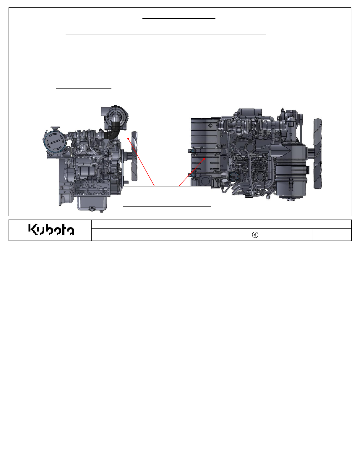
2-2-2. Standard Air
Incorrect air intake
T
he standard air intake
Intake System
system lay
system lay
Layout
Layout for D1803
out
will caus
out is
illustr
2. Int
e e
missi
ated below.
ake System
-CR-TIE4B-KEA-1 and D1803
on non-compliance.
-CR-TIE4B-KEA-2 Models
Kubota Emissi
Document Number : KEA-S
on-R
elated Installation Instructions
TD-03-CRS-DOC-
001
-
④
Page No
.
19
Page 20

Append
ix 5
2-2. Standard Intake System
2-2-3. Standard Air
Incorrect air intake
T
he standard air intake
Intake System
system lay
system lay
Layout
Layout for D1803
out
will caus
out is
illustr
2. Int
e e
missi
ated below.
ake System
-CR-TIE4BG-
on non-compliance.
KEA-1
Kubota Emissi
Document Number : KEA-S
on-R
elated Installation Instructions
TD-03-CRS-DOC-
001
-
④
Page No
.
20
Page 21

Append
ix 5
2-2. Standard Intake System
2-2-4. Standard Air
Incorrect air intake
T
he standard air intake
Intake System
system lay
system lay
Layout
Layout for V2403
out
will caus
out is
illustr
2. Int
ake System
-CR-TIE4B-KEA-1 and V2403
e e
missi
on non-compliance.
ated below.
-CR-TIE4B-KEA-2 Models
Kubota Emissi
Document Number : KEA-S
on-R
elated Installation Instructions
TD-03-CRS-DOC-
001
-
④
Page No
.
21
Page 22

Append
ix 5
2-2. Standard Intake System
2-2-5. Standard Air
Incorrect air intake
T
he standard air intake
Intake System
system lay
system lay
Layout
Layout for V2403
out
will caus
out is
illustr
2. Int
-CR-TIE4BG-
e e
missi
ated below.
ake System
KEA-1
on non-compliance.
Kubota Emissi
Document Number : KEA-S
on-R
elated Installation Instructions
TD-03-CRS-DOC-
001
-
④
Page No
.
22
Page 23

Append
ix 5
2-3 Intake System Flexibility Eligib
2. Int
ility
ake System
In some cases the standard intake system layout may not fit within the OEM’s engine compartment due to interference or servic
concerns
Th
tab
Intake
. Kubota has added the intake
system flexibility
e intake system flexibility is only allowed on
le to see if the intake system
ENGINE MODE
D
1803
-CR-TIE4BG-
V
2403
-CR-TIE4BG-
D
1803
-CR-TIE4B-KEA-1 1J497-10000
D
1803
-CR-TIE4B-KEA-2 1J497-20000
V
2403
-CR-TIE4B-KEA-1 1J498-10000
V
2403
-CR-TIE4B-KEA-2 1J498-20000
systems
on engines MUST NOT be modified from the standard layout defined in the previous pages if the flexib
L
KEA-1 1J478-10000
KEA-1 1J488-10000
option
s are eligible for th
10 DIGI
T COD
options to certain engine models to overcome these installation challenges.
certain engine models and serial numbers. Please refer to the list in the below
e engine being installed i
I
NTAK
E
FLEXIBILITY OPTIONS
E SYSTEM
NOT AVAILABLE
NOT AVAILABLE
AVAILABLE
AVAILABLE
AVAILABLE
AVAILABLE
nto the OEM equipment.
FLEXIB
FLEXIB
>7HU
>7HU
>7HU
>7HU
SERIAL
**** (Pr
**** (Pr
**** (Pr
**** (Pr
NUMBER BREAK:
ILITY NOT AVAILABLE
ILITY NOT AVAILABLE
oduced from Oc
oduced from Oc
oduced from Oc
oduced from Oc
ility is
t. 2017
t. 2017
t. 2017
t. 2017
not
available in the above table.
eab
ility
)
)
)
)
*See the next
slides
for flexib
ility
option definitions and
limi
tations.
Kubota Emissi
Document Number : KEA-S
on-R
elated Installation Instructions
TD-03-CRS-DOC-
001
-
④
Page No
.
23
Page 24

Append
ix 5
2. Int
2-4 Intake System Flexibility Options
2-4-1. Air
For
engines eligible for intake
Opti
on #1: Rotate the air cleaner inlet relative to the air cleaner body a
Opti
on #2: Ex
Opti
on #3: Rotate the air cleaner relative to the air cleaner outlet a
Opti
on #4: Rotate the air cleaner relative to the turbo charger inlet a
Multiple combi
Intake System Flexibility Opti
system flexibility
tend the air cleaner position by insta
on Introduction
the following options are available.
lli
ng an extension pipe (OEM procured)
nations of option #1, 2, 3, and 4 are acceptable. See examples of a few variations on the next page.
U
p to 500
ake System
xis
.
xis
.
xis
.
mm
.
Kubota Emissi
Document Number : KEA-S
on-R
elated Installation Instructions
TD-03-CRS-DOC-
001
-
④
Page No
.
24
Page 25

2. Intake System
2-4 Intake System Flexibility Options
2-4-2. Examples
Multiple combi
combi
nation of option #1, 2, 3, and 4is available except for
Opti
on #1: Rotate the air cleaner inlet relative to the air cleaner body a
Opti
on #2: Ex
Opti
on #3: Rotate the air cleaner relative to the air cleaner outlet a
Opti
on #4: Rotate the air cleaner relative to the turbo charger inlet a
nations of option #1, 2, 3, and 4 are acceptable. Some examples of intake
tend the air cleaner position by insta
Opti
of Air
Intake System Flexibility Combi
Opti
on #1: 180 deg.
on #2: 200 mm extension
Opti
on #3: 40 deg.
O
#
limi
lli
ng an extension pipe (OEM procured)
Opti
nation
s
system installations are show
tations shown on the following pages.
xis
.
.
xis
.
xis
.
Opti
on #1: 0 deg.
on #2: No extension
Opti
on #3: 50 deg.
n below. Any
Opti
on #1: 90 deg.
Opti
on #2: 100 mm extension
Opti
on #3: 285 deg.
Append
ix 5
Kubota Emissi
Document Number : KEA-S
on-R
elated Installation Instructions
TD-03-CRS-DOC-
001
-
④
Page No
.
25
Page 26

Append
ix 5
2-4 Intake System Flexibility Options
2-4-3. Air
S
ee below for installation
Opti
on #1: Rotate the air cleaner inlet relative to the air cleaner body a
T
he air cleaner that is provided for the standard
adjust the air cleaner inlet to any angle (0-360 deg.) as
Intake System Flexibility Opti
not
es and limitations for option
on #1
KEA
engines with intake
illustr
2. Int
ake System
#1.
xis
.
system flexibility
ated below except for the
has a rotatable inlet. It is acceptable to
limi
tations outlined in the following pages.
Kubota Emissi
Document Number : KEA-S
on-R
elated Installation Instructions
TD-03-CRS-DOC-
001
-
④
Page No
.
26
Page 27
2-4 Intake System Flexibility Options
2-4-4. Air
S
ee below for installation
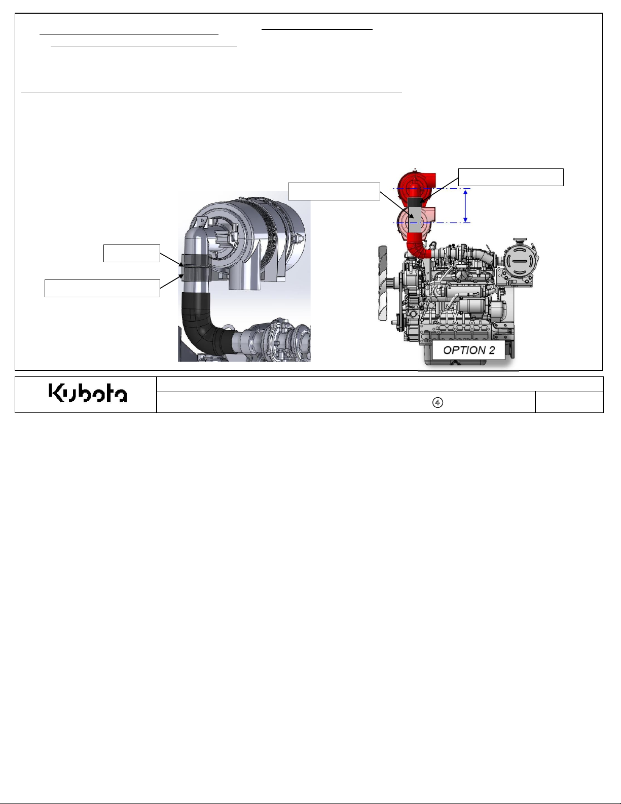
Opti
on #2: Ex
Th
e extension pipe must be OEM procuredand it must comp
A.T
he OEM must use the rubber coupling which is supplied by Kubota.
B.T
he rubber coupling must fit tightly on the air cleaner and extension pipe in order to avoid dust in the intake
C.T
he OEM must install a hose clamp on each end of the rubber coupling to avoid dust in the intake
D.N
o gap is allowed between the extension pipe and air cleaner outlet. (S
E.“Flexibility” engines include an air cleaner with a rotatable outlet. There is possibility that the air cleaner outlet could r
pipe weight, vibration, etc. It is the responsib
able to guarantee that the extension pipe installation angle follows the design intent angle throughout the life of the machine.
F.S
ee the next page for detailed extension pipe requirements and dimensions.
Intake System Flexibility Opti
not
es and limitations for option
tend the air cleaner position as
on #2
illustr
ated below except for the
ility
of the OEM to evaluate if the air cleaner extension pipe requires support. The OEM must be
2. Intake System
#2.
limi
tations outlined in the following pages.
ly with the below requirements:
ee image below)
EXTENSION PI
PE
system
system
.
.
RU
NO GAP
RU
BBER COUPLIN
G
Append
otate due to the extension
BBER COULPING
< 500
mm
ix 5
Kubota Emissi
Document Number : KEA-S
on-R
elated Installation Instructions
TD-03-CRS-DOC-
001
-
④
Page No
.
27
Page 28

Append
ix 5
2-4 Intake System Flexibility Options
2-4-4. Air
Installation
Opti
on #2: Ex
Extension Pipe Requirement
G
. The pipe must be clean and de-burred prior to installation.
H
. The pipe must be seamless stainless steel or aluminum (re
I. The pipe must fall within the dimensions outlined in the below drawing.
J
. Pi
pe spec must follow ASTM A
Intake System Flexibility Opti
not
es and limitations for option
tend the air cleaner position as
s and Dimensions
511, ASTM A
on #2
#2
illustr
ated below except for the
:
519, or
2. Int
conti nued…
sis
similar s
ake System
tant to corrosion).
tandards.
limi
tations outlined in the following pages.
FOR 7” Air Cleaner
(2 3/8” OD)
FOR 8” Air Cleaner
(3 ½” OD)
Kubota Emissi
Document Number : KEA-S
on-R
elated Installation Instructions
TD-03-CRS-DOC-
001
-
④
Page No
.
28
Page 29

Append
ix 5
2. Int
ake System
2-4 Intake System Flexibility Options
2-4-5. Air
S
ee below for installation
Opti
on #3: Rotate the air cleaner relative to the air cleaner outlet a
It is acceptable to adjust the air cleaner installation to any angle (0-360 degree)
the following pages.
Intake System Flexibility Opti
not
es and limitations for option
on #3
#3.
xis
.
illustr
ated below except for the
limi
tations outlined in
Kubota Emissi
Document Number : KEA-S
on-R
elated Installation Instructions
TD-03-CRS-DOC-
001
-
④
Page No
.
29
Page 30

Append
ix 5
2. Int
ake System
2-4 Intake System Flexibility Options
2-4-6. Air
S
ee below for installation
Opti
on #4: Rotate the air cleaner relative to the turbo charger inlet a
It is acceptable to adjust the air cleaner installation to exactly90 degrees as
pe
rmi
tted. Als
Intake System Flexibility Opti
not
es and limitations for option
o, see other
limi
tations outlined in the following pages for option #4.
on #4
#4.
xis
.
illustr
ated below. Other angles besides 90 degree are not
Kubota Emissi
Document Number : KEA-S
on-R
elated Installation Instructions
TD-03-CRS-DOC-
001
-
④
Page No
.
30
Page 31

Append
ix 5
2. Int
2-5 Intake System Flexibility Limi
2-5-1. Air
S
ee below for installation limitations for the following engines
D
1803
-CR-TIE4B-KEA-1 (1J497-10000
D
1803
-CR-TIE4B-KEA-2 (1J497-20000
S
ee below for air cleaner installation locations that are NOT acceptable. These installations cause the mass air flow sensor to fall
outside of the acceptable sensor performance range.
Intake System Flexibility Limi
tation
)
)
s
tation
s
ake System
:
Configuration NOTacceptable for D1803-CR-TIE4B-KEA-1, D1803-CR-TIE4B-KEA-2
AIR CLEANER INSTALLATION ANGLE
EXTENSION PIPE NOT
INSTALLED (OPTION #2).
AIR INLET HOSE (1J497-1164
STANDARD POSITION
(OPTION
#4
0 DEG.
)
△ )
(OPTION
THIS CONFIGURATION
IS NOT ALLOWED
#3): Perpendicular to Crankshaft 0 +/-45
AIR CLEANER INLET ANGLE
(OPTION
#1): Downward Facing 180 +/-90
°
°
Kubota Emissi
Document Number : KEA-S
on-R
elated Installation Instructions
TD-03-CRS-DOC-
001
-
④
Page No
.
31
Page 32

Append
ix 5
2. Int
2-5 Intake System Flexibility Limi
2-5-2. Air
S
ee below for installation limitations for the following engines
D
1803
-CR-TIE4B-KEA-1 (1J497-10000
D
1803
-CR-TIE4B-KEA-2 (1J497-20000
If the air inlet hose is rotated 90 deg. about the turbo charger a
acceptable:
A.T
he exactcombination of AC
B.Any
other combination not
Intake System Flexibility Limi
Inlet, AC Angl
lis
ted in this table is not pe
tation
s
tation
s
)
)
e, and Heights in this table can be used as specified.
ake System
:
xis (
option #4), the following air cleaner installation combinations ARE
rmi
tted.
Inlet Hose Angle
(Option #4)
Acceptable Combinations for D1803-CR-TIE4B-KEA-1, D1803-CR-TIE4B-KEA-2
ACInlet ACAngle Height
90 90 Standard ( 0mm Extension )
0 180 Standard ( 0mm Extension )
90 180 St andard ( 0mm Extension )
0 270 Standard ( 0mm Extension )
90 270 St andard ( 0mm Extension )
0 90 Extension =250mm Fixed Length
90 90 Extension = 500 mm Fixed Length
0 180 Extension =500mm Fixed Length
270 270 Extension = 500mm Fixed Length
ACInlet
(Option #1)
Height
(Option #2)
ACAngle
(Option #3)
Kubota Emissi
Document Number : KEA-S
on-R
elated Installation Instructions
TD-03-CRS-DOC-
001
-
④
Page No
.
32
Page 33

Append
ix 5
2. Int
2-5 Intake System Flexibility Limi
2-5-3. Air
S
ee below for installation limitations for the following engines
V
2403
-CR-TIE4B-KEA-1 (1J498-10000
V
2403
-CR-TIE4B-KEA-2 (1J498-20000
If the air inlet hose is rotated 90 deg. about the turbo charger a
acceptable:
A.T
he exactcombination of AC
B.Any
other combination not
Intake System Flexibility Limi
Inlet, AC Angl
lis
ted in this table is not pe
tation
s
tation
s
)
)
e, and Heights in this table can be used as specified.
ake System
:
xis (
option #4), the following air cleaner installation combinations ARE
rmi
tted.
Inlet Hose Angle
(Option #4)
Acceptable Combinations for V2403-CR-TIE4B-KEA-1, V2403-CR-TIE4B-KEA-2
ACInlet ACAngle
0 90 90 St andard ( 0 mm Extension )
180 90 90 Standard ( 0mm Extension )
180 180 90 Standard ( 0mm Extension )
0 270 90 Standard (0 mm Ext ension )
180 90 90 Extension = 250 mm Fixed Length
0 180 90 Extension = 250 mm Fixed Length
180 90 90 Extension = 500 mm Fixed Length
Inlet Hose
Angle
Height
ACInlet
(Option #1)
Height
(Option #2)
ACAngle
(Option #3)
Kubota Emissi
Document Number : KEA-S
on-R
elated Installation Instructions
TD-03-CRS-DOC-
001
-
④
Page No
.
33
Page 34

Append
ix 5
2-6 Intake System
1.Air cl
2. Air i
eaner vibration:
-Accelerati
-Vibrati
ntake temperature should be checked during the app
- T
he air inlet temperature should not be more than 5 deg. C higher than ambient temperature, othe
performance
-
If the temperature is high a pre
Installation
on/
Displacem
on must be checked during the app
will
be reduced.
ent must not exceed the
-cl
eaner hose can be added to the air cleaner to
help reduce inlet temperature.
3. En
vironm
ent:
-
It is
critical
that water does not enter the intake
-Add a pre
-T
he dust evacuation valve must point downward to prevent water from entering
-cl
eaner hose and/or rain cap as necessary.
the air cleaner.
4. Pre-Cl
eaner Hose Requirements:
- FEA supplied pre
-cl
eaner hose:
- Thickness ≥ 6 mm (for rubber molded hoses)
- T
he inner surface of the pipe should be smooth.
5. Air Cl
eaner Brack
- T
he OEM is responsible to prepare the air cleaner mounting bracket if the
et:
air cleaner is moved from the standard position (intake
2. Int
licati
on review.
system
ake System
limits prescri
licati
.
system flexibility)
bed in the app
on review:
licati
on review form.
rwis
e engine
.
Kubota Emissi
Document Number : KEA-S
on-R
elated Installation Instructions
TD-03-CRS-DOC-
001
-
④
Page No
.
34
Page 35

Append
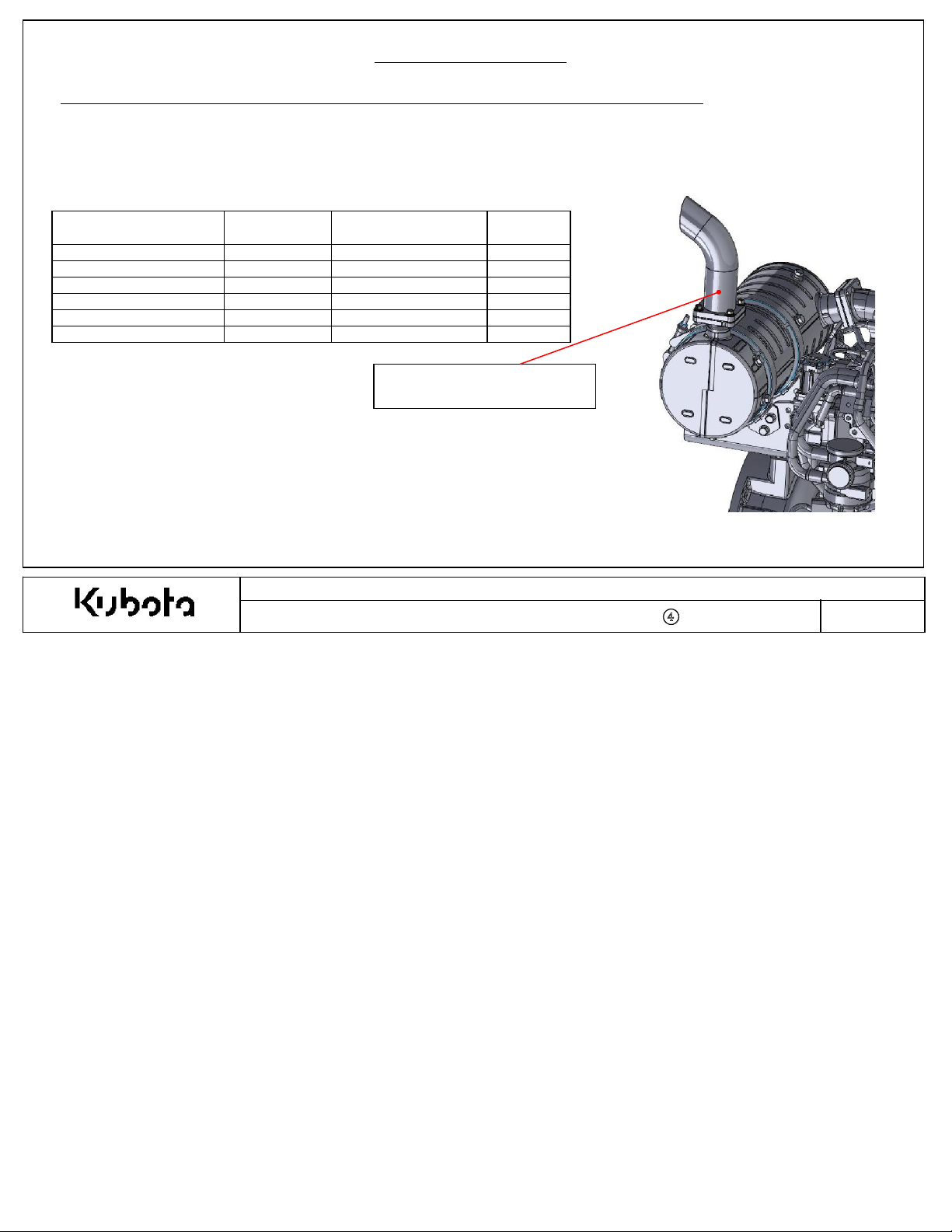
V2403- CR- TIE4BG- KEA- 1 250 500
Intake Resistance
ix 5
2. Int
2-7. Intake Re
T
o prevent decreases of engine output performance and to maintain e
less
than the following
is c
hanged the intake rest
- Measurem
-Measur
- Measure i
sis
tance
limits
. If a pre
ricti
on MUSTbe checked during the app
ent point of intake re
e as close as po
ntake rest
ssibl
ricti
on at rated speed, full load.
-cl
eaner hose, rain cap, or any other modification from the standard intake
sis
tance is between the air cleaner and the inlet of the turbo charger.
e to the compressor inlet.
ake System
Measurem
Poi
nt
ent
missi
on compliance, the total intake
licati
on review with the final intake
Engine Model
D1803- CR- TIE4B- KEA- 1 400 630
D1803- CR- TIE4B- KEA- 2 400 630
D1803- CR- TIE4BG- KEA- 1 250 500
V2403- CR- TIE4B- KEA- 1 400 630
V2403- CR- TIE4B- KEA- 2 400 630
system restricti
system c
Initial limit
w/ clean
filter
(mmH2O)
system c
onfiguration.
Limit
w/ dirty
filter
(mmH2O)
on must be
onfiguration
Kubota Emissi
Document Number : KEA-S
on-R
elated Installation Instructions
TD-03-CRS-DOC-
001
-
④
Page No
.
35
Page 36

Append
ix 5
2-8. Charge Air Cooler
T
he Kubota 03
mai
ntain e
-CRS DOC engines require a charge air cooler. To prevent decreases of engine output performance and to
missi
on compliance, the charge air cooler must meet the following
Installation Requirement
temperature drop MUSTbe checked during the app
1.Ma
ximum allowabl
2.Ma
ximum allowabl
N
ote: Measure charge air cooler pressure drop and intake manifold temperature at rated speed, full load.
e pressure drop from turbo charger outlet to intake manifold inlet = <10 kP
e temperature at intake manifold inlet = < Ambi
2. Int
s
licati
ake System
on review.
criteri
ent + 25
a. The charge air cooler pressure drop and
a
° C
Kubota Emissi
Document Number : KEA-S
on-R
elated Installation Instructions
TD-03-CRS-DOC-
001
-
④
Page No
.
36
Page 37

Append
ix 5
3-1. Fuel System S
upp
3-1-1. Fuel System S
Fuel system m
A
n example of the standard fuel
show
n below. An alternative fuel
m
anual.
⑨Fuel C
eans the layout of all parts from the fuel tank to the fuel rail and back.
= Fuel S
= Fuel R
upply
eturn
ap
⑩
Clam
p
ly
upply for
system lay
system lay
⑬Fuel
Cooler
⑤⑥⑦
Eye-bolt
A
ssy
3. Fuel System
KEA S
tandard CRS-DOC Engines
out for the 03
out can be found in the app
⑧C
oupler
A
ssy
-CRS-DOC
⑫Fuel Hos
⑪T
fitt
e
①Li
engine is
licati
ft Pump
on
Comm
Rail
on
Engi
ne: V2403
(some com
-CR-TIE
4
ponents not shown
Pre
-
S
upply
Pum
p
)
S
upply
Pum
p
④W
S
eparato
ater
r
Document Number : KEA-S
②Check
Valv
Kubota Emissi
e
on-R
elated Installation Instructions
TD-03-CRS-DOC-
001
③Filter
-
④
Page No
.
37
Page 38

3. Fuel System
Supplied
Comes with Water In Fuel sensor installed
K
ubota has the parts shown in the previous drawing and recommends that these parts be used in the fuel
FEA supplied parts must meet the installation instruction requirements.
system
Append
ix 5
.
No. Part Name FEA
1 Pump, Electric Lift
2 Valve, Check
3 Fuel Filter Assembly
4 Wat er Separat or Assembly
5 Joint, Bolt
6 Joint, Eye
7 Washer, Packing
8 Coupler Assy, Electrical
9 Fuel Cap
10 Clamp, hose
11 Tee fitt ing, 8mm ID
12 Hose, Fuel
13 Cooler, Fuel
○
○
○
○
○
Kubota
○
○
○
○
○
○
○
○
KBT Part No. Q'ty Engine Model Remarks
1G639- 5203△ 1 All 03 Series
1G911- 4246△ 1 All 03 Series
1J456- 4301△ 1 All 03 Series
2
1J430- 4335△ 1 All 03 Series
16541- 9579△ 4 All 03 Series M14x1.5 thread, used for inlet/ outlet of Separator and Filter
15401- 9569△ 4 All 03 Series Used for inlet/ outlet of Separator and Filter
17105- 3368△ 8 All 03 Series Used for inlet/ outlet of Separator and Filter
19838- 6583△ 1 All 03 Series Electrical connector for electric lift pump
- 1 All 03 Series
- 18 All 03 Series for 8mm ID fuel hose
- 2 All 03 Series for 8mm ID fuel hose, one after Separat or, one before Filter
- - All 03 Series 8mm ID fuel hose, rat ed for f uel per SAE 30R9
- - All 03 Series Fuel cooler may be added to keep temperature < 75° C
Kubota Emissi
on-R
elated Installation Instructions
Document Number : KEA-S
TD-03-CRS-DOC-
001
-
④
Page No
.
38
Page 39

3. Fuel System
Append
ix 5
3-2. Fuel System
3-2-1. Fuel System
Incorrect fuel
Fuel System layout must comply with the following:
1. To maintain e
These Tier
pump are mounted to the engine and must remain in this configuration. The fuel supply lines, return
hoses, and other loose components must be installed according to the guidelines shown on the following
pages.
Layout
Layout for
system lay
missions complianc
4 common rail engines ut
KEA CRS-DOC S
out may cause decreased engine performance and/or fuel
tandard Engines
e
ilize com
system
durab
pute
r-c
ontrolled fuel injection. The Pre-Supply and Supply
ility issues
.
Kubota Emissi
Document Number : KEA-S
on-R
elated Installation Instructions
TD-03-CRS-DOC-
001
-
④
Page No
.
39
Page 40

3-3. Fuel Line
3-3-1. Fuel Hose Measurement for
Fuel pressur
Review. Please note the expected values and measurement locations
e and temperature measurements are taken during the Ap
3. Fuel System
KEA CRS-DOC S
tandard Engines
to Fu
el Rail
Append
ix 5
= Fuel S
= Fuel R
upply
eturn
D
esign Target
Fuel Pressure < 20 kP
Kubota Emissi
Document Number : KEA-S
on-R
a
D
Fuel > -
elated Installation Instructions
TD-03-CRS-DOC-
001
-
④
esign Target
30 kP
Fuel <
75
° C
a
Page No
.
40
Page 41

3-4. Fuel Pump and Check Valve
from Water
Separato
r
Installation Requirements
Elect
150mm pigtail with Yaz
c
onnector 7122-2820-
te
rminals
:
rical c
onnection in
7114-2630-02
3. Fuel System
Pair
of slots for M6
m
ounting bolt.
Bar
b fittings for
8mm ID hose
to Fu
Append
el Filte
ix 5
r
1. Ma
ximum vibrati
2. Pump can be mounted in ho
on levels not to exceed 3G.
riz
ontal or vertical orientation.
4. Do not mount Pump in high temperature en
vironm
ents which can create cavitation or vapor lock conditions.
Kubota Emissi
Document Number : KEA-S
on-R
elated Installation Instructions
TD-03-CRS-DOC-
001
-
④
Page No
.
41
Page 42

3. Fuel System
Append
ix 5
3-5. Fuel
Filter
and Water Separato
K
ubota supplies fuel filter (1J456-4301
Fuel filter shall
be installed between feed pump and injection pump.
W
W
ater-In-Fuel Sensor:
1J430-4388
C
onnector: AMP
JuniorPowe
△
rTimer
o
282911
r
△ )
.
S
upply
Pum
p
= Fuel S
upply
= Fuel R
eturn
M14x
1.5 x 15mm
ports for banjo
fitting
s
Fuel
Inlet
r
PWR
SENGND
Fuel Filter
uel Outlet
12V –Switched Powe
Kubota Emissi
Document Number : KEA-S
on-R
r
elated Installation Instructions
TD-03-CRS-DOC-
001
-
④
Page No
.
42
Page 43

3. Fuel System
Append
ix 5
3-6 Fuel System
1. Vibrati
on must be checked during the app
- Fuel Pum
- Fuel Pum
- Fuel Filter accelerati
- Fuel Filter displacem
Installation
licati
on review:
p acceleration must not exceed 2
p displacement must not exceed 0.5mm continuous at any condition.
on must not exceed 5
ent must not exceed 0.7mm continuous at any condition.
G’s continuous
2. Fuel temperature should be checked during the app
- T
he temperature should not be more than 75
3. Installation/orientation of Components:
- W
ater separator and fuel filter should be mounted with the filter oriented vertica
- F
eed pump and check valve can be mounted vertica
4. En
vironm
ent:
-
It is
critical
that water content in fuel does not exceed 0.14%.
-
It is
critical
that Bio c
-
It is strongly recommended to not use zinc coated fuel tank or components.
ontent does not exceed 5% ASTM D
5. Fuel component Requirements:
- FEA-sourc
- Fuel Filter
ed Supply/Return hose:
- Hos
e I.D. = 8mm nomina
-Supply pressure > -30 kPa @
- Temper
- R
ature < 75
eturn pressure < 20 kPa @
l
° C @
the supply pump
the supply pump
the tan
:
- Filtration ≥ 98.7% at 3-5µm (per ISO
k
19438
G’s c
ontinuous at any condition.
at any condition.
licati
on review:
° C
.
lly or
ho
riz
onta
6751, EN
)
lly
.
lly
.
14214 (7%; EU EN 590: 2009
)
Kubota Emissi
Document Number : KEA-S
on-R
elated Installation Instructions
TD-03-CRS-DOC-
001
-
④
Page No
.
43
Page 44

Append
ix 5
4. Engine Control Unit (ECU
1. Operational Specification
1-1. Operating voltage : 8 to 16 VDC
1-2. Max. Vibrati
on : 5G
1-3. Normal operating temperature : -30 to 105
1-4. Water Pr
2. Installation Note
oof : IP69
s
2-1. The ECU mus
2-2. The ECU
temperature must be checked during the app
2-3. The ECU vibrati
2-4. The ECU mus
s
.
K
t be mounted on the equipment cha
on levels must be checked during the app
t be mounted within the installation angles shown below:
° C
ssis
. Engine mounted ECU's ar
licati
on review.
licati
on review.
)
e not approved for warranty.
Kubota Emissi
Document Number : KEA-S
on-R
elated Installation Instructions
TD-03-CRS-DOC-
001
-
④
Page No
.
44
 Loading...