

Kubota D1803-CR-TIE4B-KEA-2, D1803-CR-TIE4B-KEA-1, D1803-CR-TIE4BG-KEA-1, V2403-CR-TIE4B-KEA-1, V2403-CR-TIE4B-KEA-2 Installation Instructions Manual
...
K
ubota
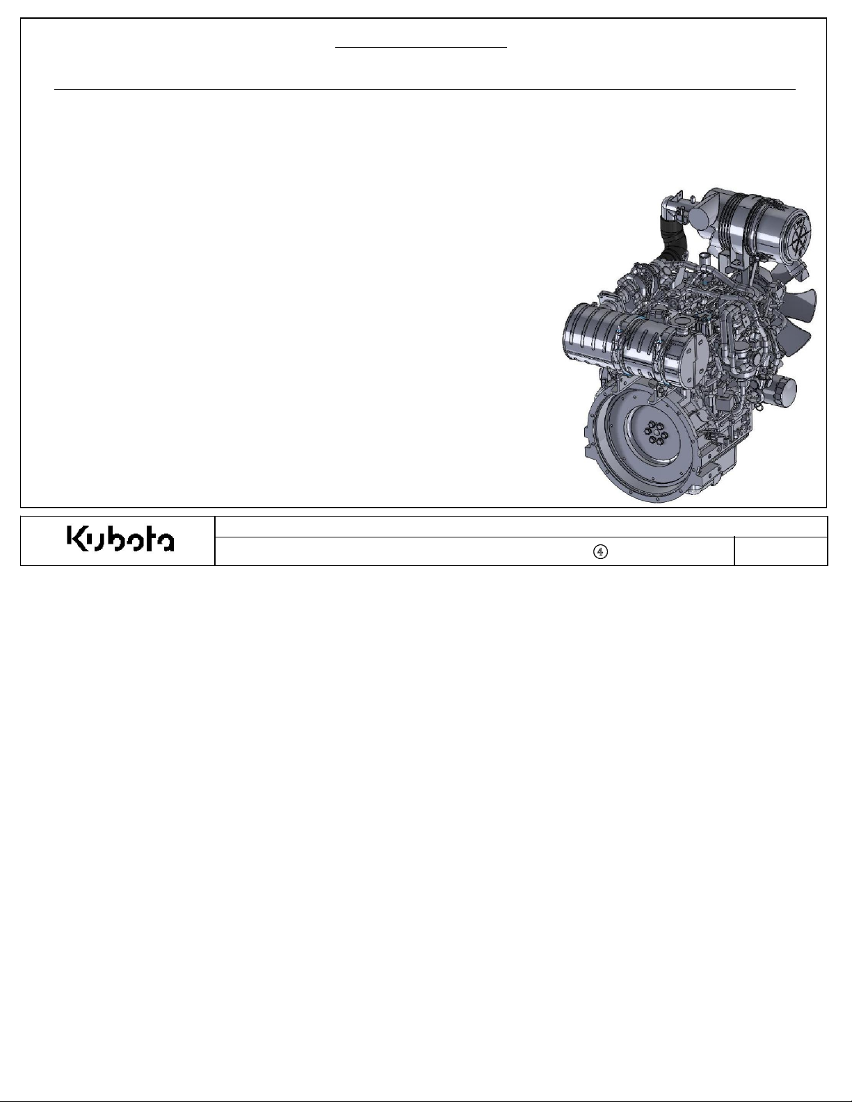
Installation Instructions
CAR
B/EPA certified Tier
4f engines:
D1803-CR-TIE4B-KEA-1 (1J497-10000)
D
1803-CR-T
D
1803-CR-T
V2403-CR-T
V2403-CR-T
V2403-CR-T
IE4B-KEA-2 (1J497-20000
IE4BG-KEA-1 (1J478-10000
IE4B-KEA-1 (1J498-10000
IE4B-KEA-2 (1J498-20000
IE4BG-KEA-1 (1J488-10000
Append
ix 5
)
)
)
)
)
T
he instructions in this document supersede any other previous instructions provided by Kubota.
Kubota Emissi
Document Number : KEA-S
on-R
elated Installation Instructions
TD-03-CRS-DOC-
001
-
④
Page No
.
1
Contents
Append
ix 5
Important Notice
Objectiv
1. Ex
e Items
haust System ------------------------------------------------------------
----------------------------------------------------------------
-----------------------------------------------------------------
2. Intake System ---------------------------------------------------------------
3.Fuel System -----------------------------------------------------------------
4.Engine Control Unit (E
5. Engine Control System (Wire Harness
6.Certification Labels
7.App
licati
on Review Requirement
8. Installation Instructions Re
CU) ----------------------------------------------
/
Display P
ane
l)----------
-------------------------------------------------------
s--------------------------------------
visi
on Log
----------------------------------
page 3
page 4-5
page 6-15
page 16-36
page 37-43
page 44-57
page 48-50
page 51
page 52
page 53
Kubota Emissi
Document Number : KEA-S
on-R
elated Installation Instructions
TD-03-CRS-DOC-
001
-
④
Page No
.
2
Append
ix 5
Important Not
ice
EMISSION-RELATED INSTALLATION INSTRUCTIONS
These instructions ar
the engine, exhaust
sensor), engine control system etc, are installed correctly in the engine’s certifi
c
onfiguration. The e
tail pipe or
wir
e harness and contro
useful life of the component without any failure.
Faili
ng to follow these instructions when insta
piece of nonroad equipment violates federal law (40
and is subject to fines or other penalties as de
e provided for the final engine assemblers (FEA) who must ensure
system (After Treatment De
missi
on related parts which FEA pr
ls) mus
t be designed to function throughout the
vic
e: ATD), i
lli
scri
ntake
system (Air flow
epare (for example the exhaust
ng a certified engine in a
CFR
1068.105(b)),
bed in the Clean Air Act.
ed
Kubota Emissi
Document Number : KEA-S
on-R
elated Installation Instructions
TD-03-CRS-DOC-
001
-
④
Page No
.
3

1. Exhaust Syste
K
ubota supplies a certified diesel oxidation cata
m
treatment and assemble the exhaust
for use with these
KEA s
tandard engine models. Therefore, no other exhaust after treatment can be used.
Objective Items
lyst (DOC) assembly. FEA must use the Kubota supplied certified exhaust after
system
parts according to the instructions. No other exhaust after treatment is certified
Append
ix 5
2. Intake Syste
These Tier
m
4 common rail engines ut
iliz
e a mass air flow (MAF) sensor to control the EGR flow rate. The air cleaner location
and piping layout must be installed according to these installation instructions to maintain proper performance of the MAF
sensor
output. Als
resis
tance and charge air cooler performance must be kept within certain
3. Fuel Syste
m
In order to maintain the common rail fuel injection pump performance and durab
mus
t be checked during the app
o, to prevent decreases of engine output performance and to maintain e
criteri
a.
ility
the pressure and temperature of the fuel
licati
on review.
missi
on compliance, intake
4. Engine Control System (Engine Control Unit (ECU)
T
he Engine Control Unit (E
correctly
within K
and that the requirements and specifications are checked during the app
ubota specification. Othe
5. Engine Control System (Engine Control Unit (ECU), Wire Harness, Operator Display Panel
T
he
wir
e harness is also considered an e
correctly
and that the requirements and specifications are checked during the app
be within Kubota specification. Othe
CU) is consider
rwis
e, engine and e
rwis
e, engine and e
ed an e
missi
on control de
missi
missi
on control de
missi
Kubota Emissi
Document Number : KEA-S
vic
e. It is
critical
to ensure that the ECU is install
licati
on review. The elect
on performance cannot be guaranteed.
)
vic
e. It is
critical
to ensure that the
wir
licati
on review. The elect
on performance cannot be guaranteed.
on-R
elated Installation Instructions
TD-03-CRS-DOC-
001
-
④
rical si
e harness is installed
rical si
ed
gnal must be
gnals must
Page No
.
4
Objective Items
Append
ix 5
6. Certif
7.
ication Labels
K
ubota insta
lls
the certification label on the
cyli
nder head cover. If the final engine assembler insta
makes the engine’s emission control information label hard to read during normal
assembler must place a dup
App
lication Review Requirements
Distri
butor is responsible for completing full app
lic
ate label on the equipment, as de
licati
on review for standard engine to ensure quality engine installation. The
scri
bed in 40
lls
the engine in a way that
engine maintenance, the final engine
CFR
1068.105.
application review should be completed according to Kubota’s application review standards and application manual
r
equirements.
Kubota Emissi
Document Number : KEA-S
on-R
elated Installation Instructions
TD-03-CRS-DOC-
001
-
④
Page No
.
5
Append
ix 5
1-1. Ex
1-1-1. Ex
haust System S
haust System S
Exhaust
A
system m
n example of exhaust
upp
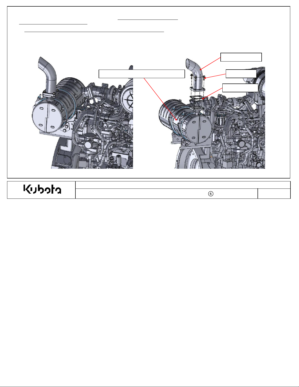
1. Exhaust System
ly
upply for
eans the layout of all parts from the exhaust manifold to the exhaust exit.
KEA S
tandard CRS-DOC Engines
system is show
N
o.1 : Diesel Oxi
n below.
dation Cata
lyst (DOC)
N
o.4 : Tail Pi
N
o.3 : Bolt
N
o.2 : Gasket
pe
Kubota Emissi
Document Number : KEA-S
on-R
elated Installation Instructions
TD-03-CRS-DOC-
001
-
④
Page No
.
6
supplied
1J497- 1810△ 1 D1803- CR- TIE4 Engine Code: 1J497- 10000 , 1J478- 10000
1J807- 1810△ 1 D1803- CR- TIE4 Engine Code: 1J497- 20000
1J808- 1810△ 1 V2403- CR- TIE4 All V2403- CR- TIE4 Models
M8 x 1.25mm ISO 8.8
Meet t he back pressure and flange requirements.
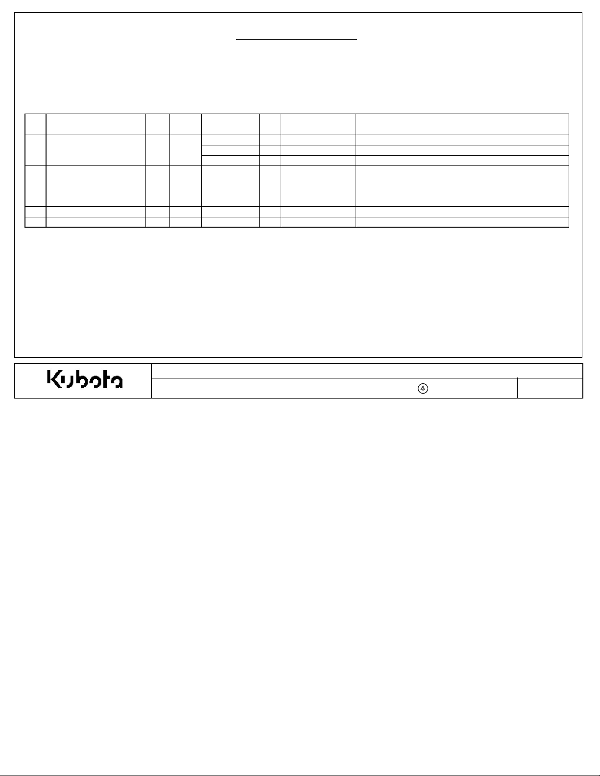
1. Exhaust System
K
ubota supplies the following parts as shown below, these parts must be used in the exhaust
FEA supplied parts must meet the installation instruction requirements.
system
Append
ix 5
.
No. Part Name FEA
Diesel Oxidation Catalyst1
2 Gasket
3 Bolt
4 Tail Pipe
N
ote: Part numbers / assemblies for item #1, Diesel Oxi
○
○
Kubota
○
○
KBT Part No. Q'ty Engine Model Remarks
Qty: 1 Gasket supplied with engine.
17326- 1223△ 1 All 03 Series
Qty: 3 Gaskets are required for remote DOC installation.
(See page 12- 13 f or remote DOC installation details)
- 4
- -
dation Cata
Kubota Emissi
Document Number : KEA-S
lys
t, vary based on the base engine.
on-R
elated Installation Instructions
TD-03-CRS-DOC-
001
-
④
Page No
.
7
1-2. Ex
haust System
Layout
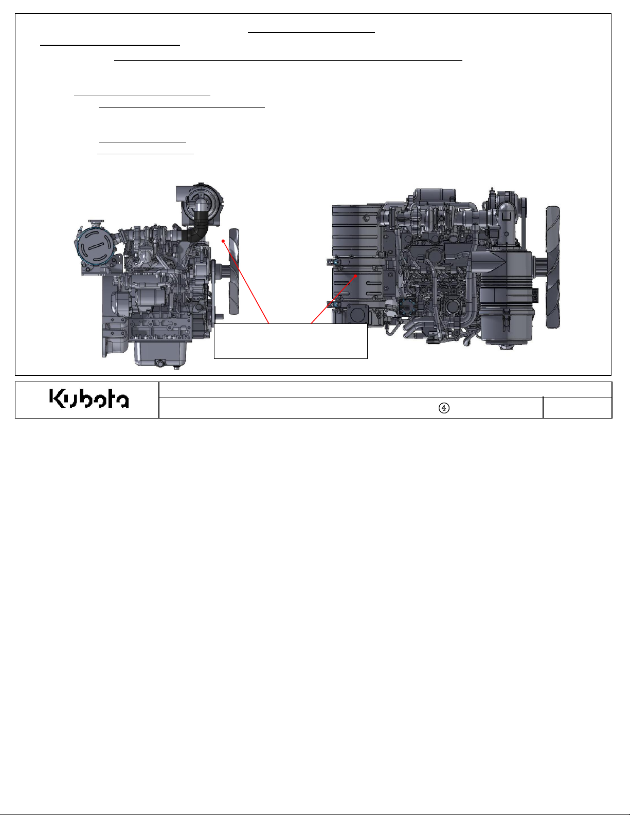
DOC (Diesel Oxidation Cata
Incorrect DOC inst
allation will cause emission
1-2-1. DOC Installation Options:
A
. Standard DOC Installation Position: T
K
ubota production fa
cility as
the standard configuration. Kubota recommends to keep the DOC in this
factory location.
B. DOC Outlet
C. Remote
It is
critical
Angle: C
Mount DOC: Certai
hanging the DOC outlet angle is acceptable. See following pages.
n app
to follow the instructions outlined in this installation manual to guarantee e
1. Exhaust System
lyst)
Installation for
he DOC is installed onto the top side of the f
lications will r
KEA CRS-DOC S
non-comp
equire for the DOC to be relocated.See following pages.
tandard Engines
liance and/or damage to the DOC
lyw
heel housing at the
missi
on compliance.
Append
ix 5
.
DOC (Diesel Oxidation Cata
Factory
Document Number : KEA-S
Location
Kubota Emissi
lyst)
on-R
elated Installation Instructions
TD-03-CRS-DOC-
001
-
④
Page No
.
8
Industrial
Industrial
BG
Industrial
Industrial
BG
1. Exhaust System
Append
ix 5
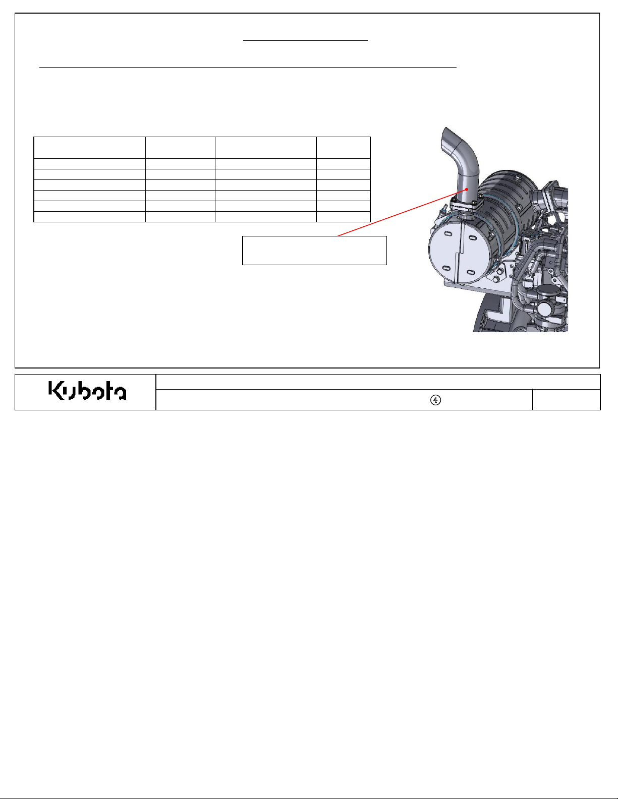
1-2-1.A Factory Mounted Installation Position (DOC): Ex
Back pressur
Measurem
Engine Model 10 Digit Code Maximum Back Pressure Remarks
D1803- CR- TIE4B- KEA- 1 1J497- 10000 50 mm Hg
D1803- CR- TIE4B- KEA- 2 1J497- 20000 50 mm Hg
D1803- CR- TIE4BG- KEA- 1 1J478- 10000 40 mm Hg
V2403- CR- TIE4B- KEA- 1 1J498- 10000 50 mm Hg
V2403- CR- TIE4B- KEA- 2 1J498- 20000 50 mm Hg
V2403- CR- TIE4BG- KEA- 1 1J488- 10000 40 mm Hg
e of exhaust tail pipe at full load, rated speed condition must be according to table below.
ent point of back pressure of exhaust
system is within 1” (25.4 mm) of the DOC outlet.
Back Pressure Measurement
Location
haust Back Pressure Check
Kubota Emissi
Document Number : KEA-S
on-R
elated Installation Instructions
TD-03-CRS-DOC-
001
-
④
Page No
.
9
1. Exhaust System
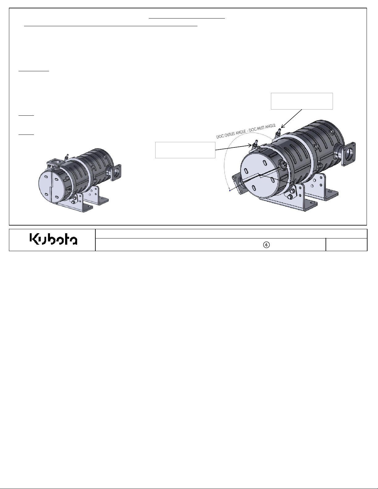
1-2-1.B DOC Outlet Angle Adjustment Proc
1.Kubota recommends to keep the DOC outlet angle in the standard position, but certain app
2.Adjusting the DOC outlet angle is acceptable to meet the installation requirements of the machine.
•Installati
•Angle adjustment must be completed only 1 time (to min
•Angle adjustment must be completed before customers run the engine(to min
on instructions must be carefu
lly
followed to ensure e
edure (Option)
missi
imize risk
of clamp breakage).
on compliance.
imize risk
lications will r
of clamp deterioration due to heat).
equire adjustment.
Append
ix 5
Procedure
STEP
STEP
STEP
STEP
STEP
N
ote 1: It is NOT allowed to adjust the DOC inlet portion of the DOC.
Only
N
ote 2: Any exhaust gas leakage or failures due to incorrect modification is not
cover
:
1: Loosen DOC band clamp at DOC outlet position and remove DOC outlet portion.
2: Replace gasket with new parts. Refer to
3: Ori
ent the DOC outlet to the de
4: Tighten Band clamp nut to 16-20 Nm.
5: Start engine and conf
the DOC outlet position can be adjusted.
ed under standard/e
irm
missions warr
sir
that there are no exhaust leaks.
anty.
STANDARD DOC CONFIGURATIO
ed angle
illustr
ated parts
(similar
lis
to image to the right).
Loosen This DOC
B
and Clamp
N
Kubota Emissi
Document Number : KEA-S
t for gasket P/N.
A
DJUSTED DOC OUTLET ANGLE
on-R
elated Installation Instructions
TD-03-CRS-DOC-
001
-
④
Do NOT
DOC B
Loosen This
and Clamp
Page No
.
10
1. Exhaust System
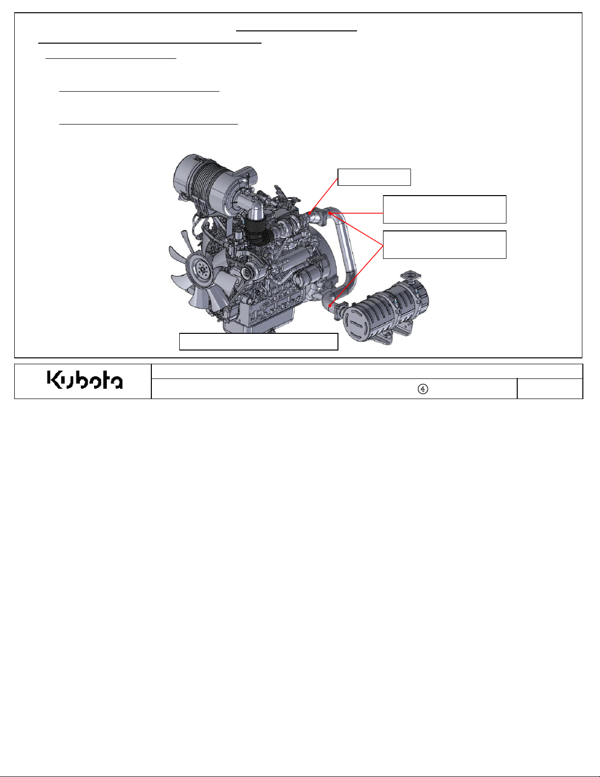
1-2-1.C Remote Mounting the DOC (Option)
Rem
ote DOC Installation Option
Certai
n app
lications will r
equire for the DOC to be relocated.See below installation
criteri
Append
ix 5
a.
1.Exhaust Backpr
A.T
outlet must be less than 113
essure Requirement:
he ma
ximum allowabl
e exhaust back pressure for the complete exhaust
mmH
2.Exhaust Temperature Drop Requireme
A. T
he ma
ximum allowabl
r
ated speed full load condition. Ex
e temperature drop across the intermediate exhaust pipe must be less than 25 deg. C at the
EXAMPLE REMOTE MO
system measur
ed at the muffler flange
g. The back pressure must be measured at the rated speed full load condition.
nt:
haust pipe insulation may be required and is recommended to meet this requirement.
M
uffler Flange
Measurem
Exhaust Back Pressur
Measurem
ent Location for
e
ent Location for
Exhaust Temperature (∆T)
UNT DOC
Kubota Emissi
on-R
elated Installation Instructions
Document Number : KEA-S
TD-03-CRS-DOC-
001
-
④
Page No
.
11
1. Exhaust System
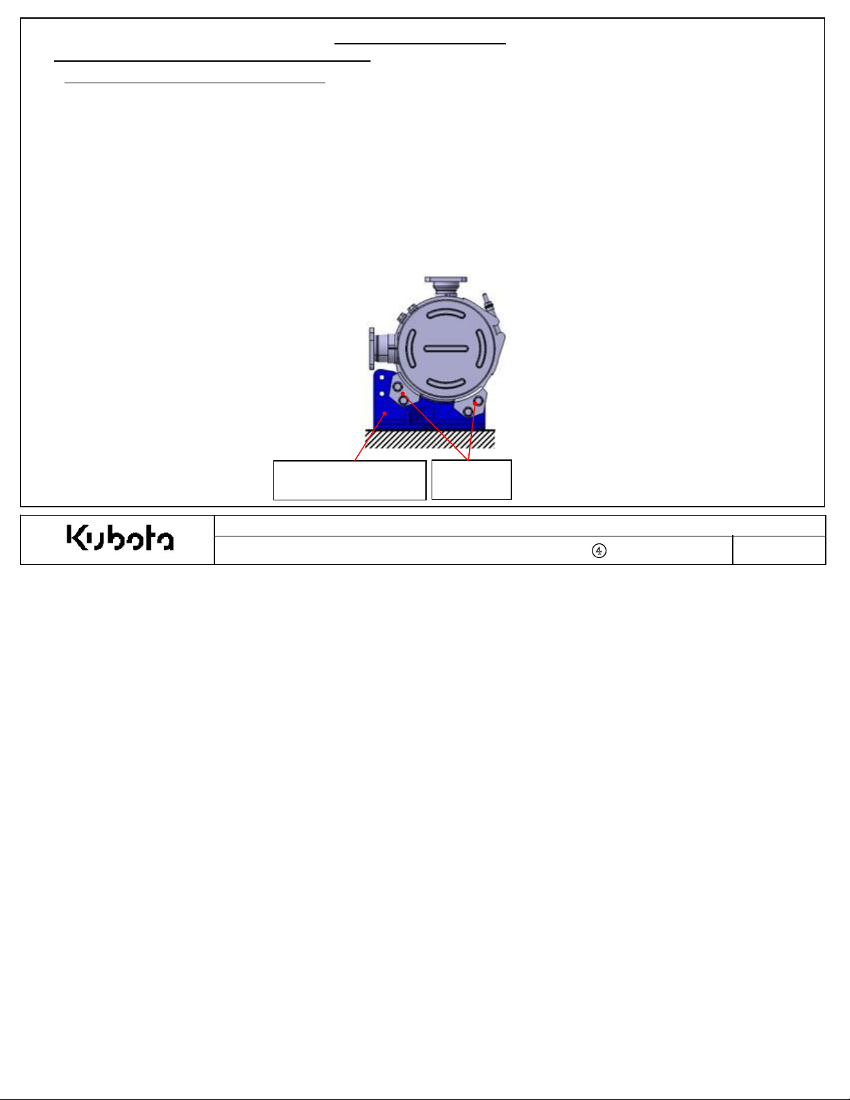
1-2-1.C Remote Mounting the DOC (Option)
Remote DOC Installation Option Continued…
Append
ix 5
3. Other Inst
A
. Intermediate pipe for remote DOC (from turbo-out to DO
B.T
he muffler flange must not be removed from the engine. The intermediate exhaust pipe must connect to the outlet of the
m
uffler flange.
C.T
he intermediate exhaust pipe and flexible coupling must not leak exhaust gases during operation.
D.New m
remov
E.Ti
ghtening torque for the muffler flange outlet and DOC inlet M8 fasteners is 24-27
F.Reloc
G
. It is strongly recommended to use the Kubota supplied DOC mounting brackets (shown below in blue).
H.DOC incli
allation Requirements for Remotely Installed DOC
C-inlet) must incl
ude a flexible portion.
uffler flange outlet gasket, DOC inlet gasket, studs, and nuts on muffler flange outlet are required when DOC is
ed from engine for remote installation. Refer to the
ated DOC needs to be mounted without exce
illustr
ssive strain/l
ated parts
oad on V-
lis
t for the correct replacement part numbers.
N·m
.
band clamps.
nation angle must follow the required installation angles defined in the next page.
K
ubota Supplied DOC
M
ounting Brackets
V-band
Clamps
Kubota Emissi
Document Number : KEA-S
on-R
elated Installation Instructions
TD-03-CRS-DOC-
001
-
④
Page No
.
12
Append
ix 5
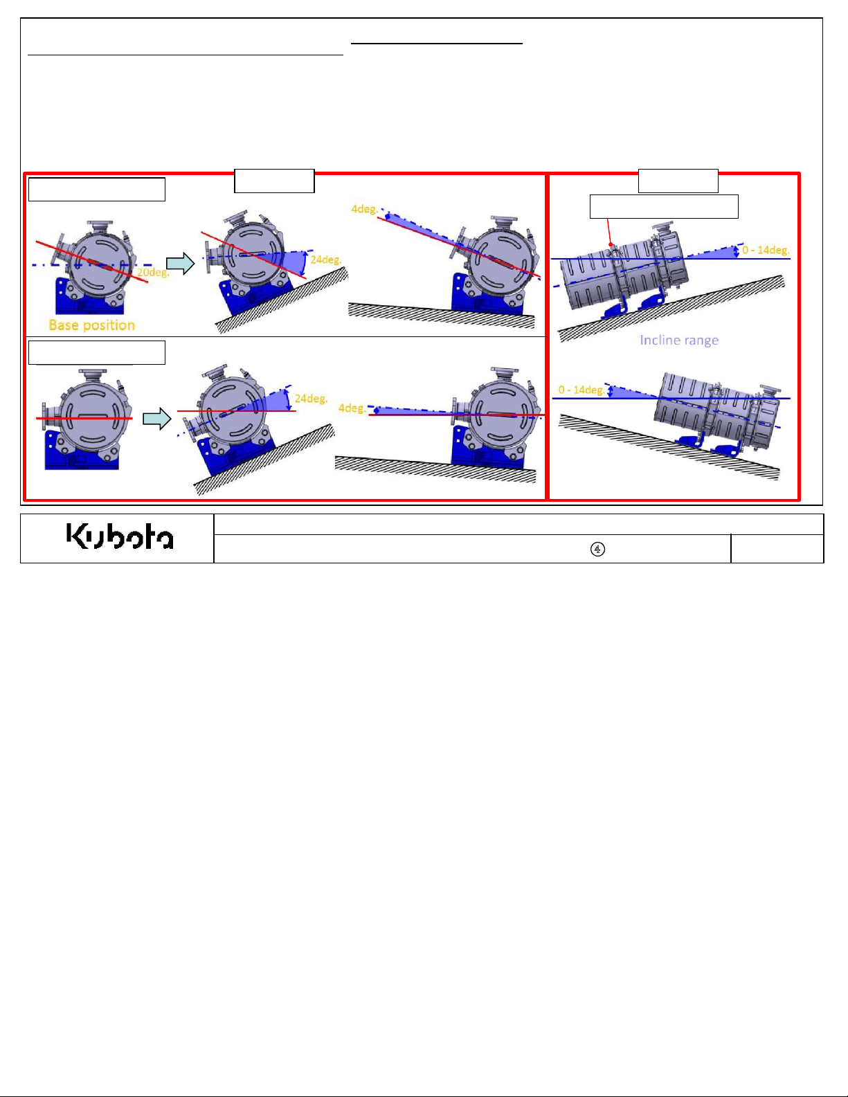
1-2-1.C Remote Mounting the DOC (Option)
4. Other Inst
A.DOC incli
B.T
C.T
D
1803
V
2403
he DOC inlet band clamp cannot be loosened or modified in any way.
he DOC can only be in
-CR-TIE4B-***
-CR-TIE4B-***
allation Requirements for Remotely Installed DOC
nation angle must be installed according to the angles defined below.
cli
ned according to option #1 or option #2, not the combination.
I.Option #1: Rotate the DOC about the DOC cente
i.Please note the required installation angle
II.Option #2: In
cli
ne the DOC up to +/-14 deg.
Option #1
1. Exhaust System
rli
ne a
xis
.
limits
below
(view
ed from DOC inlet side
Option #2
DOC
Inlet Band Clamp
)
Base position
Kubota Emissi
Document Number : KEA-S
on-R
elated Installation Instructions
TD-03-CRS-DOC-
001
-
④
Page No
.
13
1. Exhaust System
Append
ix 5
1-3 DOC
(Diesel Oxidation Cata
lyst)
Installation
Criteria {Applies for engine mounted or remote mounted DOC}
1.DOC vibration:
-Accelerati
-Vibrati
on/
Displacem
ent must not exceed the
on must be checked during the app
licati
limits prescri
on review.
bed in the app
licati
on review form.
2. The DOC shall not support mounting loads from adjacent or mated components (tail pipe/intermediate pipe):
- Check DOC
tail pipe vibration during app
licati
on review to ensure it
will
not damage the DOC during long term operation.
-
Intermediate exhaust pipe for remote mount DOC may require support brackets.
3. Pleas
4. OEM Tail Pi
e note that the DOC
- Check surr
ounding component temperatures during the app
pe Requirements:
ski
n temperature can reach about 250
° C
licati
:
on review.
- FEA supplied bolts:
- Fl
ange bolts: M8 x 1.25, strength cla
- Ti
ghtening torque; 24-27
N·m
ssificati
on is ISO
8.8
- Tail Pipe Flange:
- Fl
ange th
- Fl
atness of the flange face is ma
ickness is 8mm or mor
e.
ximum
0.1mm.
-Surface finish of the flange face is 3.2Ra.
5. Intermediate Ex
-Accelerati
app
-Vibrati
haust Pi
licati
on review form.
on/
Displacem
pe Vibrati
on: for remote mounted DO
ent must not exceed the
on must be checked during the app
licati
C
limits prescri
on review.
bed in the
Kubota Emissi
Document Number : KEA-S
on-R
elated Installation Instructions
TD-03-CRS-DOC-
001
-
④
Page No
.
14
 Loading...