

Page 1
WORKSHOP MANUAL
KiSC issued 10, 2009 A
DIESEL ENGINES
03-M-DI SERIES
Page 2

TO THE READER
KiSC issued 10, 2009 A
This Workshop Manual has been prepared to provide servicing personnel with
information on the mechanism, service and maintenance of KUBOTA Diesel Engine 03M-DI Series. It is divided into two parts, “Mechanism” and “Servicing” for each section.
Q Mechanism
Information on the Features and New Mechanisms are described. This information
should be understood before proceeding with troubleshooting, disassembling and
servicing.
Q Servicing
The heading “General” includes general precautions, check and maintenance and
special tools. There are troubleshooting, checking and adjusting, disassembling and
assembling, and servicing which cover procedures, precautions, factory specifications
and allowable limits.
All information illustrations and specifications contained in this manual are based on
the latest product information available at the time of publication. The right is reserved
to make changes in all information at any time without notice.
Due to covering many models of this manual, illustration being used, have not been
specified as one model.
March 2002
© KUBOTA Corporation 2002
Page 3
03-M-DI Series, WSM
KiSC issued 10, 2009 A
SAFETY INSTRUCTIONS
SAFETY INSTRUCTIONS
SAFETY FIRST
This symbol, the industry’s “Safety Alert Symbol”, is used throughout this manual and on labels on
the machine itself to warn of the possibility of personal injury. Read these instructions carefully.
It is essential that you read the instructions and safety regulations before you attempt to repair or use
this unit.
DANGER : Indicates an imminently hazardous situation which, if not avoided, will result in
death or serious injury.
WARNING : Indicates a potentially hazardous situation which, if not avoided, could result in
death or serious injury.
CAUTION : Indicates a potentially hazardous situation which, if not avoided, may result in
minor or moderate injury.
Q IMPORTANT : Indicates that equipment or property damage could result if instructions are not
followed.
Q NOTE : Gives helpful information.
BEFORE SERVICING AND REPAIRING
• Read all instructions and safety instructions in this
manual and on your engine safety decals.
• Clean the work area and engine.
• Park the machine on a firm and level ground.
• Allow the engine to cool before proceeding.
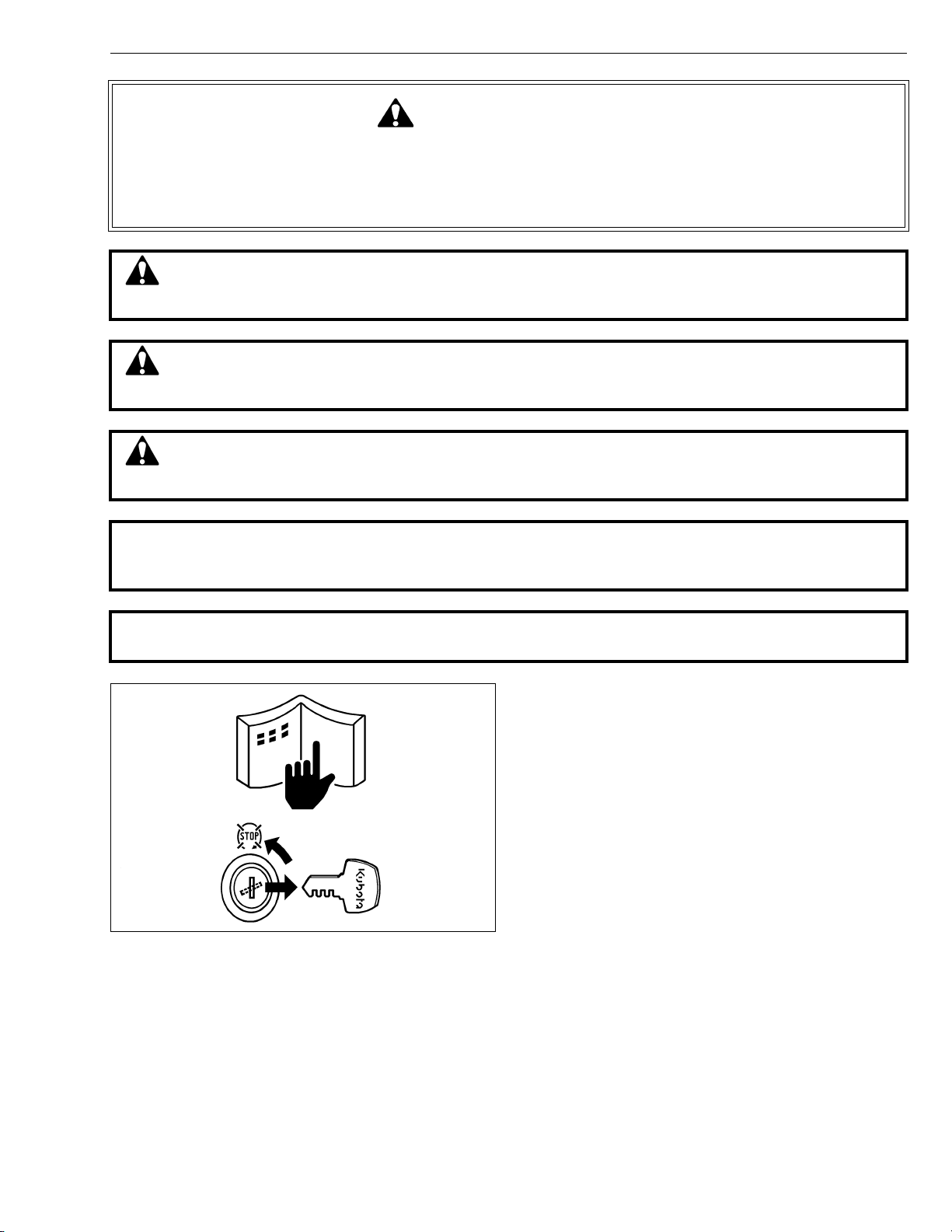
• Stop the engine, and remove the key.
• Disconnect the battery negative cable.
• Hang a “DO NOT OPERATE” tag in operator
station.
1
Page 4
03-M-DI Series, WSM
KiSC issued 10, 2009 A
SAFETY INSTRUCTIONS
SAFETY STARTING
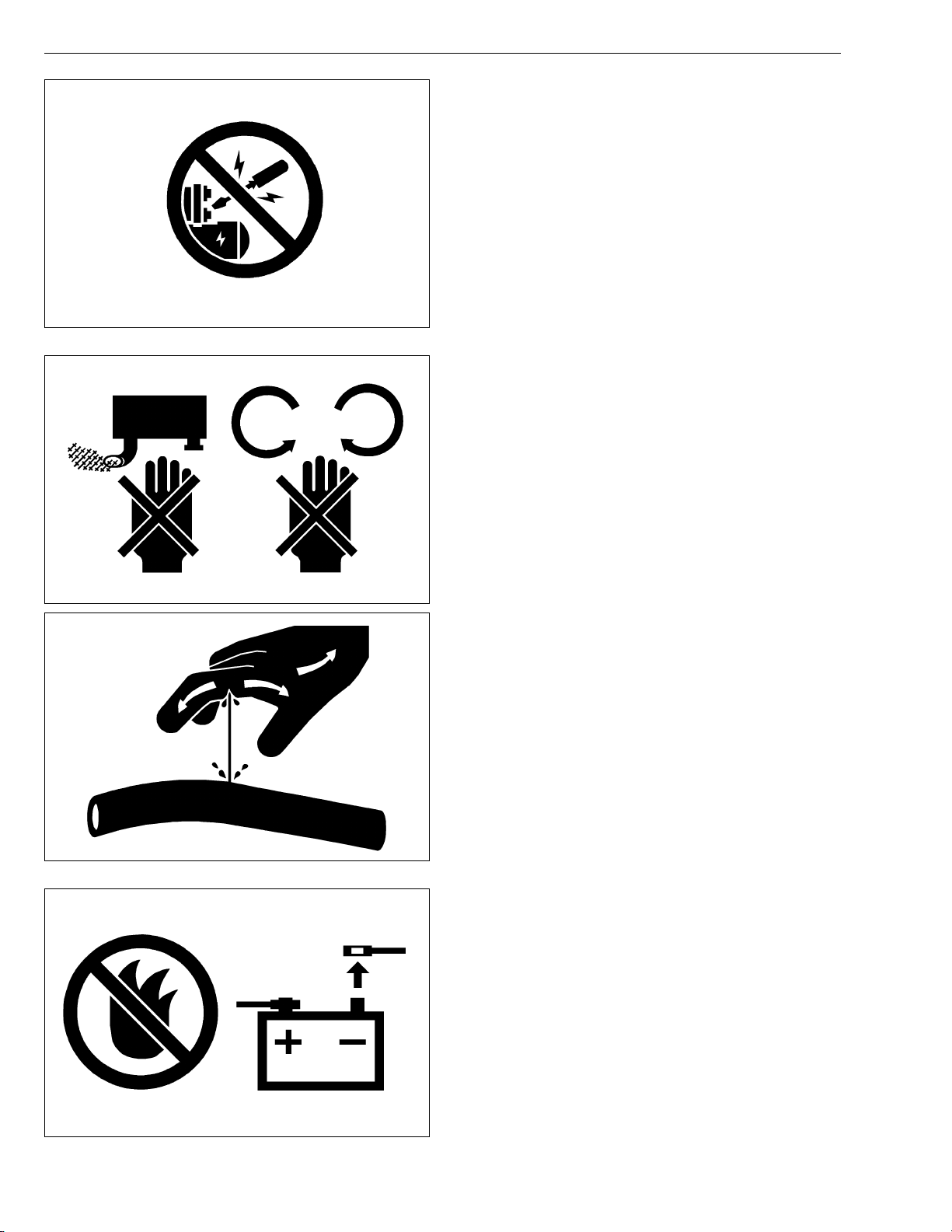
• Do not start the engine by shorting across starter
terminals or bypassing the safety start switch.
• Unauthorized modifications to the engine may impair
the function and / or safety and affect engine life.
SAFETY WORKING
• Do not work on the machine while under the influence
of alcohol, medication, or other substances or while
fatigued.
• Wear close fitting clothing and safety equipment
appropriate to the job.
• Use tools appropriate to the work. Makeshift tools,
parts, and procedures are not recommended.
• When servicing is performed together by two or more
persons, take care to perform all work safely.
• Do not touch the rotating or hot parts while the engine
is running.
• Never remove the radiator cap while the engine is
running, or immediately after stopping. Otherwise, hot
water will spout out from radiator. Only remove
radiator cap when cool enough to touch with bare
hands. Slowly loosen the cap to first stop to relieve
pressure before removing completely.
• Escaping fluid (fuel or hydraulic oil) under pressure
can penetrate the skin causing serious injury. Relieve
pressure before disconnecting hydraulic or fuel lines.
Tighten all connections before applying pressure.
• Wear a suitable hearing protective device such as
earmuffs or earplugs to protect against objectionable
or uncomfortable loud noises.
AVOID FIRES
• Fuel is extremely flammable and explosive under
certain conditions. Do not smoke or allow flames or
sparks in your working area.
• To avoid sparks from an accidental short circuit,
always disconnect the battery negative cable first and
connect it last.
• Battery gas can explode. Keep sparks and open
flame away from the top of battery, especially when
charging the battery.
• Make sure that no fuel has been spilled on the engine.
2
Page 5
03-M-DI Series, WSM
KiSC issued 10, 2009 A
SAFETY INSTRUCTIONS
VENTILATE WORK AREA
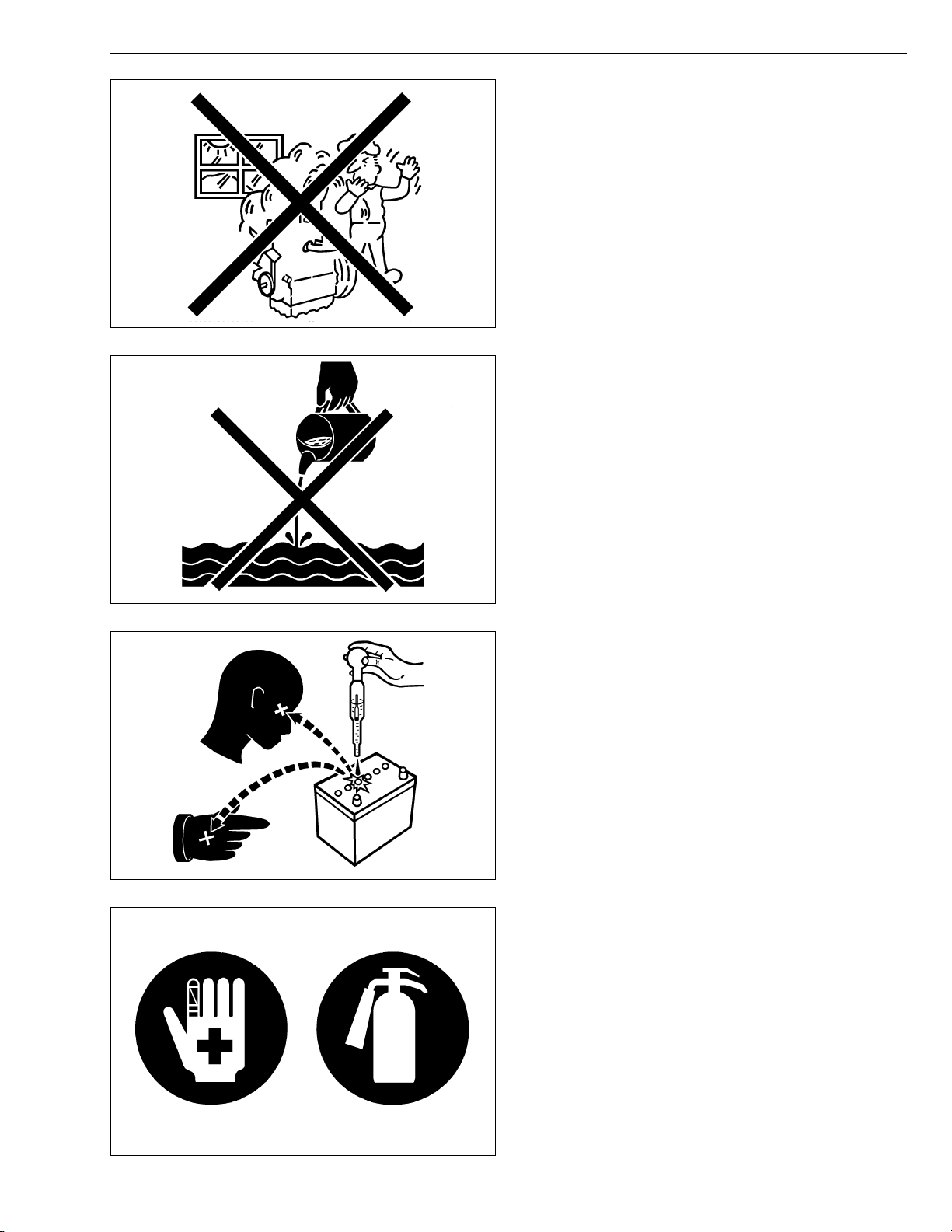
• If the engine must be running to do some work, make
sure the area is well ventilated. Never run the engine
in a closed area. The exhaust gas contains poisonous
carbon monoxide.
DISPOSE OF FLUIDS PROPERLY
• Do not pour fluids into the ground, down a drain, or
into a stream, pond, or lake. Observe relevant
environmental protection regulations when disposing
of oil, fuel, coolant, electrolyte and other harmful
waste.
PREVENT ACID BURNS
• Sulfuric acid in battery electrolyte is poisonous. It is
strong enough to burn skin, clothing and cause
blindness if splashed into eyes. Keep electrolyte
away from eyes, hands and clothing. If you spill
electrolyte on yourself, flush with water, and get
medical attention immediately.
PREPARE FOR EMERGENCIES
• Keep a first aid kit and fire extinguisher handy at all
times.
• Keep emergency numbers for doctors, ambulance
service, hospital and fire department near your
telephone.
3
Page 6
03-M-DI Series, WSM
KiSC issued 10, 2009 A
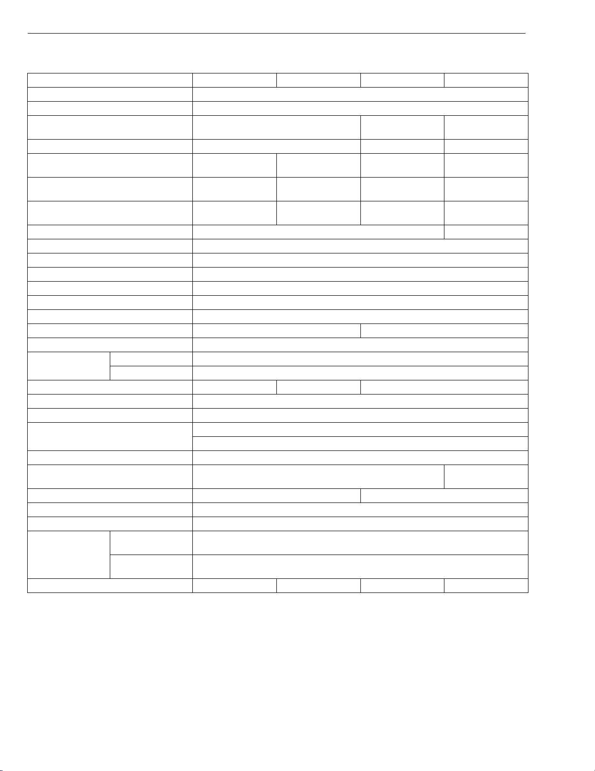
SPECIFICATIONS
SPECIFICATIONS
Model D1503-M-DI D1503-M-DI-T D1703-M-DI D1803-M-DI
Number of Cylinders 3
Type Vertical, Water-cooled, 4 cycle DI diesel engine
Bore × Stroke mm × mm
(in. × in.)
(HP/min
(HP/min
(HP/min
3
(cu.in.) 1499 (91.47) 1647 (100.51) 1826 (111.43)
-1
(rpm)
-1
(rpm))
-1
(rpm)
-1
(rpm))
-1
(rpm)
-1
(rpm))
-1
(rpm) 3000 2800
-1
(rpm) 750 to 850
20.1 / 2800
(27.0 / 2800)
23.5 / 2800
(31.5 / 2800)
24.8 / 2800
(33.2 / 2800)
Total Displacement cm
SAE Net Cont. kW/min
SAE Net Intermittent kW/min
SAE Gross Intermittent kW/min
Maximum Bare Speed min
Maximum Idling Speed min
Combustion Chamber Troiddal Type (Direct Injection)
Fuel Injection Pump Bosch “K” Type Mini Pump
Governor Centrifugal Ball Type, All Speed Mechanical Governor
Direction of Rotation Counter-Clockwise (viewed from flywheel side)
Injection Nozzle Bosch “P” Type Hole Nozzle
Injection Timing 0.201 rad (11.5 °) Before T.D.C. 0.175 rad (10 °) Before T.D.C.
Firing Order 1-2-3
Injection Pressure 1st. Stage 18.6 MPa (190 kgf/cm
2nd. Stage 22.6 MPa (230 kgf/cm
Compression Ratio 20 19 20
Lubricating System Forced Lubrication by Trochoid Pump
Cooling System Pressurized radiation, forced circulation with water pump
Starting System Electric Starting with Starter
Starting Support Device Pre-heating by Glow Plug in Combustion Chamber
Battery
12 V, 60 A (75D31R)
Charging Alternator 12 V, 360 W 12 V, 480 W
Fuel Diesel Fuel No.2-D or No.2-DLS
Lubricating Oil Better than CD class (API)
Lubricating Oil
Capacity
Oil Pan Depth
90 mm (3.54 in.)
Oil Pan Depth
124 mm (4.88 in.)
Weight (Dry) BB spec. kg (lbs) 148 (326) 152 (335) 148 (326) 151 (333)
* The specification described above is of the standard engine of each model.
* Conversion Formula : HP = 0.746 kW, PS = 0.7355 kW
83 × 92.4
(3.26 × 3.64)
27.2 / 2800
(36.5 / 2800)
31.3 / 2800
(42.0 / 2800)
32.7 / 2800
(43.8 / 2800)
5.6 L (1.48 U.S.gals)
7.0 L (1.85 U.S.gals)
12 V, 1.4 kW
87 × 92.4
(3.43 × 3.64)
22.7 / 2800
(30.4 / 2800)
26.1 / 2800
(35.0 / 2800)
27.4 / 2800
(36.7 / 2800)
2
, 2702 psi)
2
, 3271 psi)
87 × 102.4
(3.43 × 4.04)
23.9 / 2600
(32.1 / 2600)
27.2 / 2600
(36.5 / 2600)
28.4 / 2600
(38.1 / 2600)
12 V, 88 A
(115E41R)
W10275180
4
Page 7
03-M-DI Series, WSM
KiSC issued 10, 2009 A
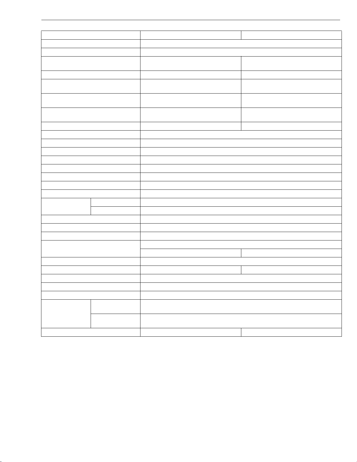
SPECIFICATIONS
Model V2203-M-DI V2403-M-DI
Number of Cylinders 4
Type Vertical, Water-cooled, 4 cycle DI diesel engine
Bore × Stroke mm × mm
(in. × in.)
3
Total Displacement cm
SAE Net Cont. kW/min
(HP/min
SAE Net Intermittent kW/min
(HP/min
SAE Gross Intermittent kW/min
(HP/min
Maximum Bare Speed min
Maximum Idling Speed min
(cu.in.) 2197 (134.07) 2434 (148.53)
-1
(rpm)
-1
(rpm))
-1
(rpm)
-1
(rpm))
-1
(rpm)
-1
(rpm))
-1
(rpm) 3000 3000
-1
(rpm) 750 to 850
87 × 92.4
(3.43 × 3.64)
30.2 / 2800
(40.5 / 2800)
34.8 / 2800
(46.7 / 2800)
36.4 / 2800
(48.8 / 2800)
87 × 102.4
(3.43 × 4.04)
31.8 / 2600
(42.6 / 2600)
36.6 / 2600
(34.8 / 2800)
38.0 / 2600
(51.0 / 2600)
Combustion Chamber Troiddal Type (Direct Injection)
Fuel Injection Pump Bosch “K” Type Mini Pump
Governor Centrifugal Ball Type, All Speed Mechanical Governor
Direction of Rotation Counter-Clockwise (viewed from flywheel side)
Injection Nozzle Bosch “P” Type Hole Nozzle
Injection Timing 0.192 rad (11 °) Before T.D.C.
Firing Order 1-3-4-2
2
Injection Pressure 1st. Stage 18.6 MPa (190 kgf/cm
2nd. Stage 22.6 MPa (230 kgf/cm
, 2702 psi)
2
, 3271 psi)
Compression Ratio 20
Lubricating System Forced Lubrication by Trochoid Pump
Cooling System Pressurized radiation, forced circulation with water pump
Starting System Electric Starting with Starter
12 V, 1.4 kW 12 V, 2.0 kW
Starting Suport Device Pre-heating by Glow Plug in Combustion Chamber
Battery 12 V, 88 A (115E41R) 12 V, 92 A (130E41R)
Charging Alternator 12 V, 480 W
Fuel Diesel Fuel No.2-D or No.2-DLS
Lubricating Oil Better than CD class (API)
Lubricating Oil
Capacity
Oil Pan Depth
90 mm (3.54 in.)
Oil Pan Depth
124 mm (4.88 in.)
7.6 L (2.01 U.S.gals)
9.5 L (2.51 U.S.gals)
Weight (Dry) BB spec. kg (lbs) 180 (397) 184 (406)
* The specification described above is of the standard engine of each model.
* Conversion Formula : HP = 0.746 kW, PS = 0.7355 kW
W10299960
5
Page 8
03-M-DI Series, WSM
KiSC issued 10, 2009 A
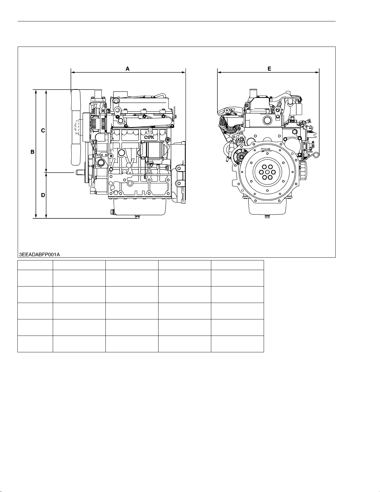
DIMENSIONS
DIMENSIONS
D1503-M-DI D1503-M-DI-T D1703-M-DI D1803-M-DI
A 599.2 mm
(23.59 in.)
B 643.5 mm
(25.33 in.)
C 414.2 mm
(16.31 in.)
D 229.3 mm
(9.03 in.)
E 514.4 mm
(20.25 in.)
599.2 mm
(23.59 in.)
644.0 mm
(25.35 in.)
414.2 mm
(16.31 in.)
229.8 mm
(9.05 in.)
514.4 mm
(20.25 in.)
572.1 mm
(22.52 in.)
643.3 mm
(25.33 in.)
414.0 mm
(16.30 in.)
229.3 mm
(9.03 in.)
507.1 mm
(19.96 in.)
575.9 mm
(22.67 in.)
685.0 mm
(26.97 in.)
419.0 mm
(16.50 in.)
266.0 mm
(10.47 in.)
499.0 mm
(19.65 in.)
W1031045
6
Page 9
03-M-DI Series, WSM
KiSC issued 10, 2009 A
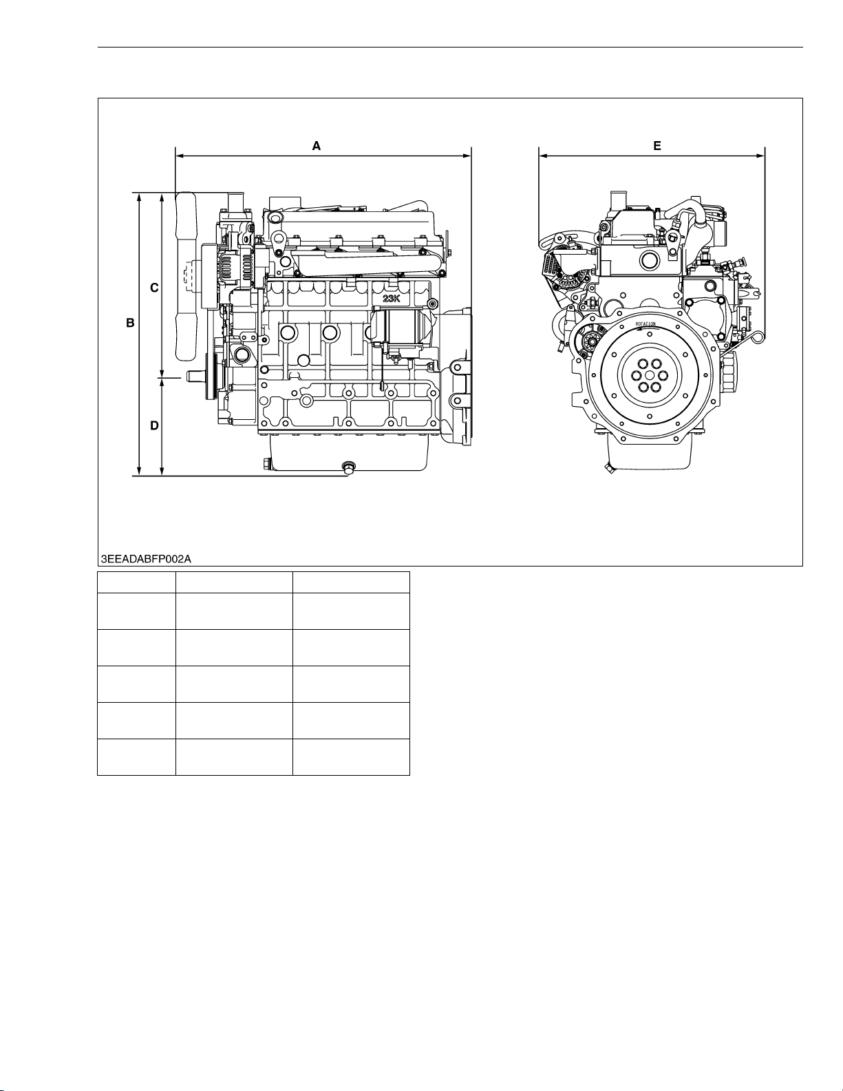
DIMENSIONS
V2203-M-DI V2403-M-DI
A 667.1 mm
(26.26 in.)
B 635.0 mm
(25.00 in.)
C 414.0 mm
(16.30 in.)
D 221.0 mm
(8.70 in.)
E 507.1 mm
(19.96 in.)
670.9 mm
(26.41 in.)
684.5 mm
(26.95 in.)
419.0 mm
(16.50 in.)
265.5 mm
(10.45 in.)
499.0 mm
(19.65 in.)
W1031355
7
Page 10

MECHANISM
KiSC issued 10, 2009 A
CONTENTS
1. ENGINE BODY ............................................................................................... M-1
[1] HOLLOW CORE ....................................................................................... M-1
[2] PISTON...................................................................................................... M-1
[3] BUILT-IN DYNAMIC BALANCER (BALANCER MODEL ONLY) ......... M-2
[4] HALF-FLOATING HEAD COVER ............................................................ M-2
2. COOLING SYSTEM........................................................................................ M-3
[1] BOTTOM BYPASS SYSTEM................................................................... M-3
3. FUEL SYSTEM ............................................................................................... M-4
[1] GOVERNOR .............................................................................................. M-4
4. ELECTRICAL SYSTEM .................................................................................. M-6
[1] STARTER AUTO REDUCTION UNIT..................................................... M-6
(1) General ................................................................................................ M-6
(2) Basic Circuit ......................................................................................... M-6
(3) Component .......................................................................................... M-7
(4) Function ............................................................................................... M-7
Page 11
03-M-DI Series, WSM
KiSC issued 10, 2009 A
1. ENGINE BODY
[1] HOLLOW CORE
[2] PISTON
DIESEL ENGINE
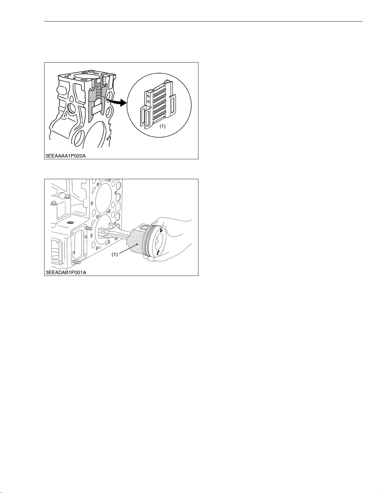
The cylinder block has a hollow core (1) already cast
inside the cylinder-to-cylinder water jacket.
In this core, there is a pair of vertical cooling
passages (right and left) as well as multiple horizontal
cooling channels that interconnect these cooling
passages. This design allows smoother cooling water
flow through the cylinder block, which cools down a wider
range between the cylinders more effectively.
(1) Hollow Core
W1013048
Piston’s skirt is coated with molybdenum
disulfide+, which reduces the piston slap noise and
thus the entire operating noise.
+Molybdenum disulfide (MoS
The molybdenum disulfide (1) serves as a solid
lubricant, like a Graphite or Teflon. This material helps
resist metal wears even with little lube oil.
(1) Molybdenum Disulfide
2)
W1013114
M-1
Page 12
03-M-DI Series, WSM
KiSC issued 10, 2009 A
DIESEL ENGINE
[3] BUILT-IN DYNAMIC BALANCER (BALANCER MODEL ONLY)
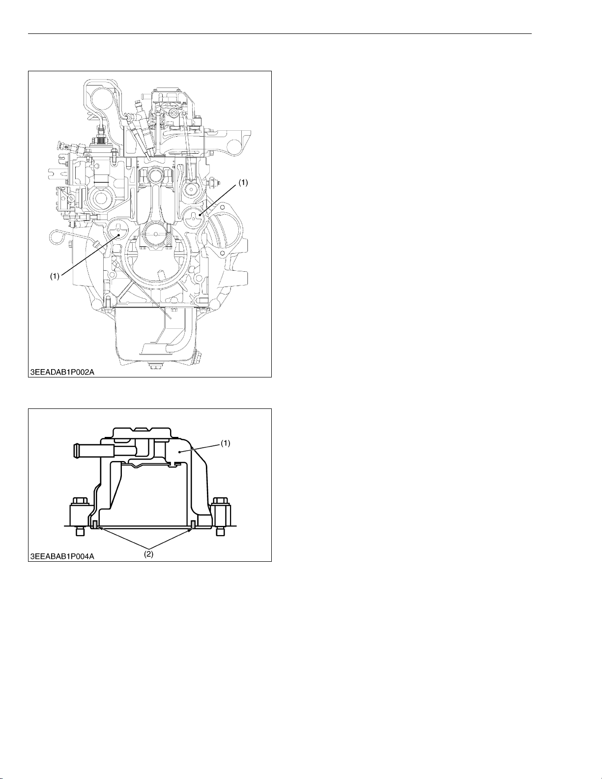
Engine are sure to vibrate by piston’s reciprocation.
Theoretically, three-cylinder engines are much less
prone to cause vibration than four-cylinder ones (second
inertia, etc.). However, any engine has many moving
parts in addition to its pistons and cannot be completely
free from vibration.
The four cylinders engine V2203 and V2403 can be
fitted with balance weight on crankcase to absorb the
second inertia mentioned above and reduce vibration.
This engine is internally provide with two balancers
(1), one at the suction side and the other at the exhaust
side.
(1) Balancer
W1013221
[4] HALF-FLOATING HEAD COVER
The rubber packing (2) is fitted in to maintain the
cylinder head cover (1) 0.5 mm or so off the cylinder
head. This arrangement helps reduce noise coming from
the cylinder head.
(1) Cylinder Head Cover (2) Rubber Packing
W1013327
M-2
Page 13
03-M-DI Series, WSM
KiSC issued 10, 2009 A
2. COOLING SYSTEM
[1] BOTTOM BYPASS SYSTEM
DIESEL ENGINE
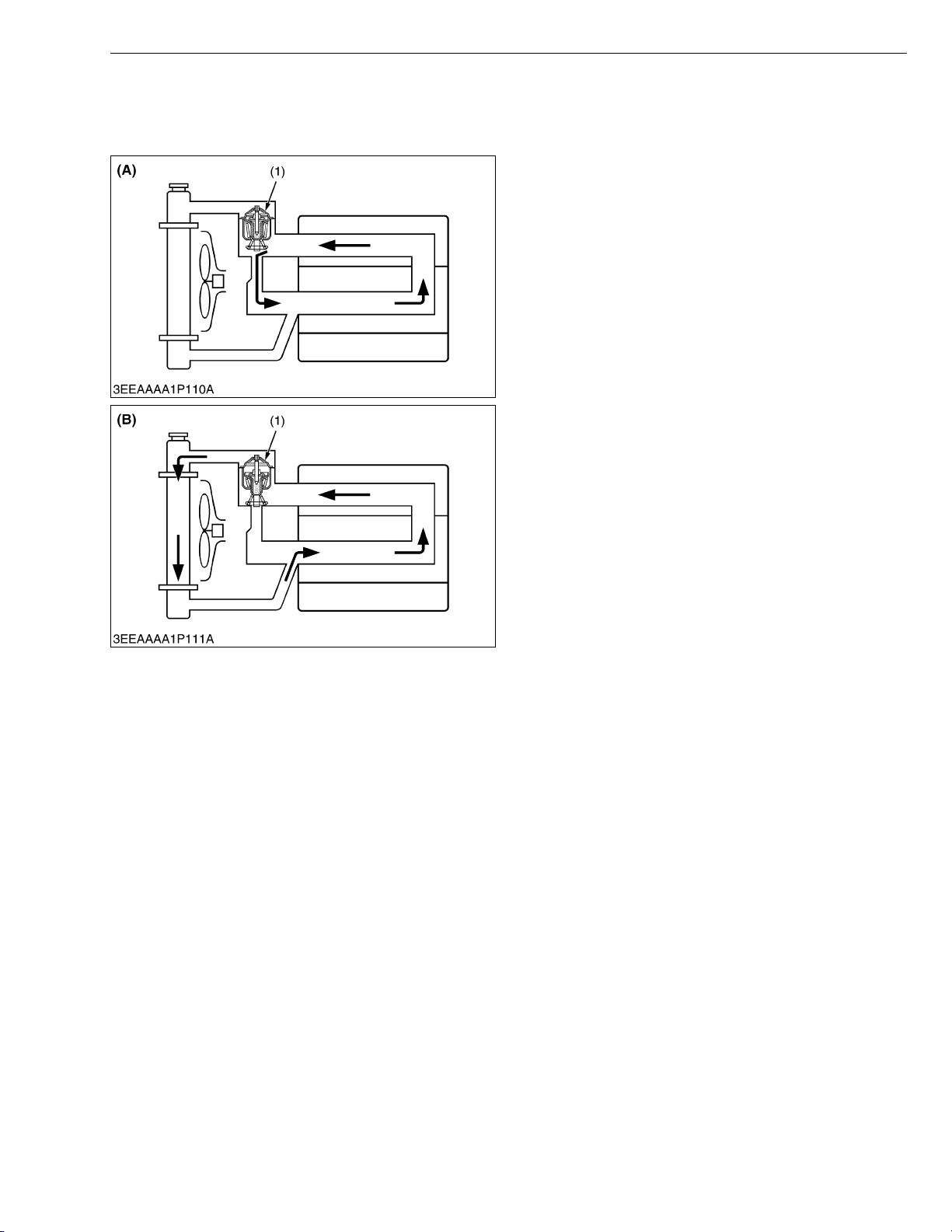
Bottom bypass system is introduced in 03-M-DI
Series for improving the cooling performance of the
radiator.
While the temperature of coolant in the engine is low,
the thermostat (1) is held closed and the coolant is
allowed to flow through the bypass pipe and to circulate
in the engine.
When the temperature exceeds the thermostat valve
opening level, the thermostat (1) fully opens itself to
prevent the hot coolant from flowing through the bypass
into the engine.
In this way, the radiator can increase its cooling
performance.
(1) Thermostat (A) Bypass Opened
(B) Bypass Closed
W1013406
M-3
Page 14
03-M-DI Series, WSM
KiSC issued 10, 2009 A
3. FUEL SYSTEM
[1] GOVERNOR
DIESEL ENGINE
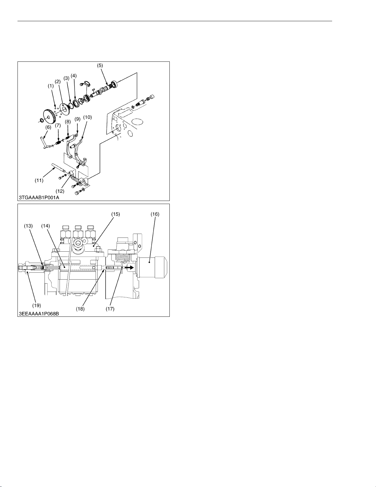
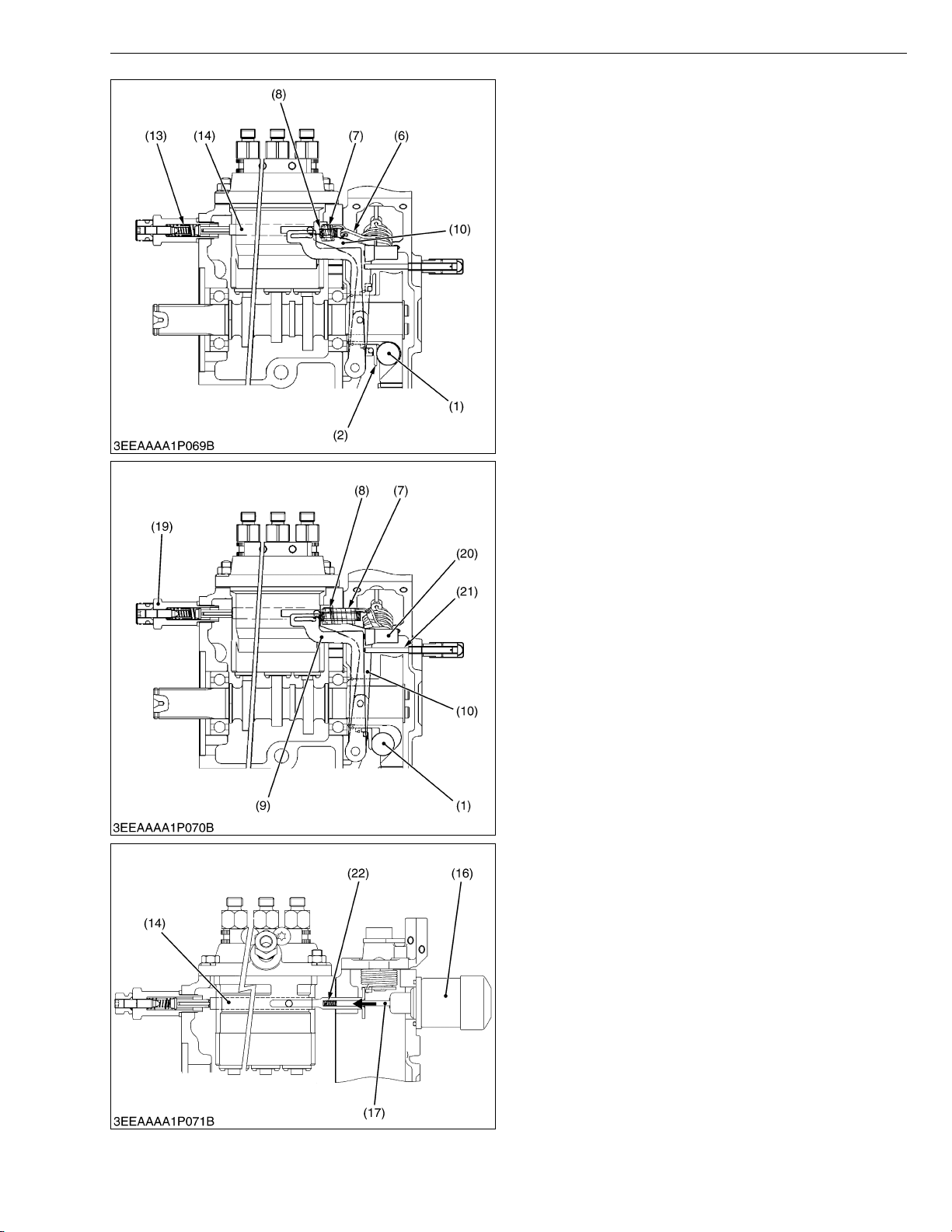
The governor serves to keep engine speed constant
by automatically adjusting the amount of fuel supplied to
the engine according to changes in the load. This engine
employs an all-speed governor which controls the
centrifugal force of the steel ball (1) weight, produced by
rotation of the fuel camshaft (5), and the tension of the
governor spring 1 (7) and 2 (8) are balanced.
(1) Steel Ball
(2) Governor Sleeve
(3) Steel Ball
(4) Governor Ball Case
(5) Fuel Camshaft
(6) Governor Lever
(7) Governor Spring 1
(8) Governor Spring 2
(9) Fork Lever 2
(10) Fork Lever 1
(11) Fork Lever Shaft
(12) Fork Lever Holder
W1017186
Q At Start
Flowing of the battery current into the engine stop
solenoid (16), the plunger (17) is actuated to arrow
direction.
Since the steel ball (1) have no centrifugal force, the
control rack (14) is pushed to the right by the start spring
(13). Accordingly, the control rack (14) moves to the
maximum injection position to assure easy starting.
(13) Start Spring
(14) Control Rack
(15) Injection Pump
(16) Engine Stop Solenoid
(17) Plunger
(18) Guide
(19) Idling Apparatus
W1017215
M-4
Page 15
03-M-DI Series, WSM
KiSC issued 10, 2009 A
DIESEL ENGINE
Q At Idling
When the speed control lever is set at the idling
position after the engine starts, the governor spring 1 (7)
does not work at all and the governor spring 2 (8) does
only act slightly. The governor sleeve (2) is pushed
leftward by a centrifugal force of steel ball (1).
Therefore, the fork lever 1 (10) and control rack (14)
are moved to the left by the governor sleeve (2) and then
the start spring (13) is compressed by the control rack
(14). As a result, the control rack (14) is kept at a position
where a centrifugal force of steel ball (1) and forces of
start spring (13), governor spring 2 (8) are balanced,
providing stable idling.
(1) Steel Ball
(2) Governor Sleeve
(6) Governor Lever
(7) Governor Spring 1
(8) Governor Spring 2
(10) Fork Lever 1
(13) Start Spring
(14) Control Rack
W1017317
Q At High Speed Running with Overload
When an overload is applied to the engine running at
a high speed, the centrifugal force of steel ball (1)
becomes small as the engine speed is dropped, and fork
lever 2 (9) is pulled to the right by the governor springs 1
(7) and 2 (8), increasing fuel injection. Though, fork lever
2 (9) becomes ineffective in increasing fuel injection
when it is stopped by the adjusting screw (21).
After that, when the force of torque spring (20)
becomes greater than the centrifugal force of the steel
ball (1), fork lever 1 (10) moves rightward to increase fuel
injection, causing the engine to run continuously at a high
torque.
(1) Steel Ball
(7) Governor Spring 1
(8) Governor Spring 2
(9) Fork Lever 2
(10)Fork Lever 1
(19) Idling Apparatus
(20) Torque Spring
(21) Adjusting Screw
W1017384
Q To Stop Engine
When the battery current stops, the plunger (17) of
engine stop solenoid (16) is returned to the original
position, the spring (22) to keep the control rack (14) in
“No fuel injection” position.
(14) Control Rack
(16) Engine Stop Solenoid
(17) Plunger
(22) Spring
M-5
W1018007
Page 16
03-M-DI Series, WSM
KiSC issued 10, 2009 A
DIESEL ENGINE
4. ELECTRICAL SYSTEM
[1] STARTER AUTO REDUCTION UNIT
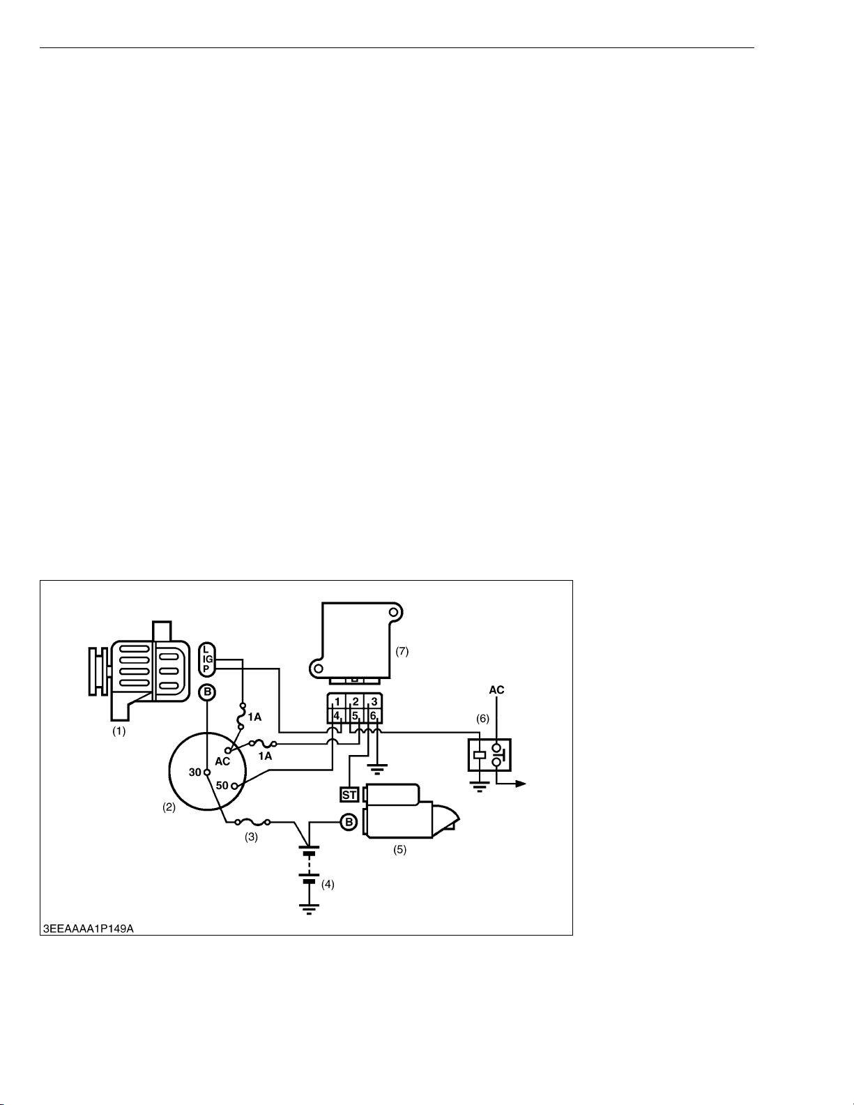
(1) General
The starter auto reduction unit (7) is designed to start the machine equipped with engine more reliably. This unit
has the following function by integrating an alternator (1) that puts out rpm-proportional pulses.
1. Fail-Safe Functions
a) Preventing the starter pinion from getting in mesh while the engine is runnning.
With the engine running, pulses from the alternator terminal P are constantly detected. Even if key switch (2) is
wrongly operated or the wiring gets short-circuited, the starter (5) can stay off, the starter (5) and flywheel ring gear
are effectively protected.
b) Starter auto reduction at a start of the engine.
When the engine has got started and the alternator (1) has reached the specified rpm, the electical current to the
starter (5) is automatically cut off, even if the key switch (2) is at the START position.
c) Safety mechanism in case of engine stall.
If the engine stalls with the key switch (2) at AC or START position, the key must be set once to OFF position for added
safety. The starter (5) is thus kept from turning on unexpectedly.
2. Other Features and Functions
a) Simplified wiring with built-in power relay.
The unit is internally provided with a power relay to get simpler wiring than ever before. If the key switch terminal AC,
ground cable or any other parts is wrongly connected, the starter (5) stays off. This helps identify wrong wiring more
easily.
b) With the output terminal for confirming engine start (Relay drive possible).
The unit has an external output terminal in order to confirm an engine start. An external relay (6) may also be
connected to this terminal. (Output current : below 200 mA)
(2) Basic Circuit
(1) Alternator
(2) Key Switch
(3) Slow Blow Fuse
(4) Battery
(5) Starter
(6) External Relay
(7) Starter Auto Reduction Unit
W1014160
M-6
Page 17
03-M-DI Series, WSM
KiSC issued 10, 2009 A
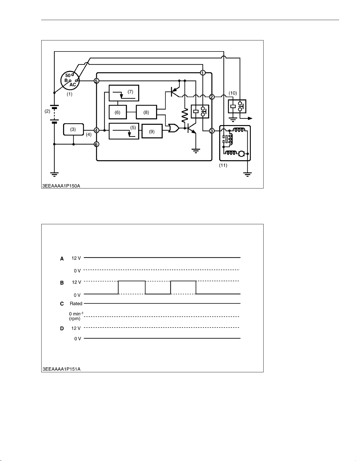
(3) Component
DIESEL ENGINE
(1) Key Switch
(2) Battery
(3) Alternator
(4) P terminal
(5) Detection High rpm (N2)
(6) Delay Curcuit
(7) Detection Low rpm (N1)
(8) Self Holding Circuit
(9) Self Holding Circuit
(10) External Relay
(11) Starter
W1014290
(4) Function
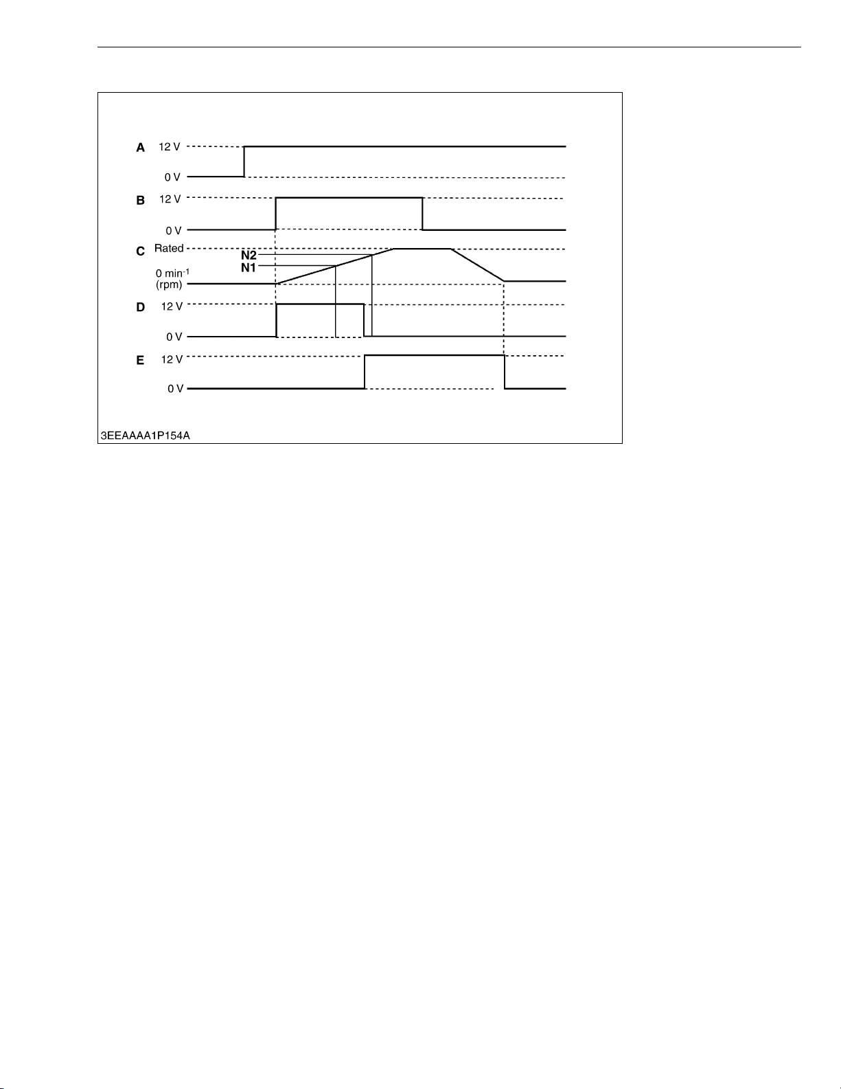
(A) Starter Auto Reduction
a) While Engine is Running
A : Key Switch AC Terminal
(Voltage)
B : Key Switch 50 Terminal
(Voltage)
C : Alternator Revolution
D : Starter ST Terminal
-1
(rpm))
(min
(Voltage)
W1014807
M-7
Page 18
03-M-DI Series, WSM
KiSC issued 10, 2009 A
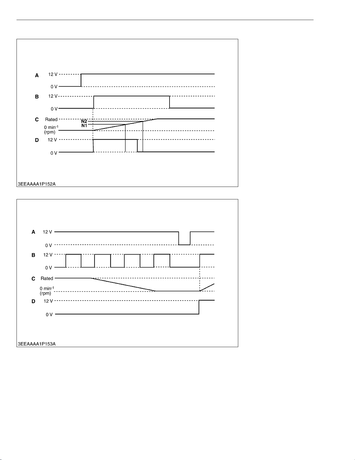
b) When Engine Starts Normally
DIESEL ENGINE
A : Key Switch AC Terminal
(Voltage)
B : Key Switch 50 Terminal
(Voltage)
C : Alternator Revolution
D : Starter ST Terminal
N1 :Detection Low rpm
N2 :Detection High rpm
-1
(rpm))
(min
(Voltage)
W1014965
c) When Engine Stalls
A : Key Switch AC Terminal
(Voltage)
B : Key Switch 50 Terminal
(Voltage)
C : Alternator Revolution
D : Starter ST Terminal
-1
(rpm))
(min
(Voltage)
W1015076
M-8
Page 19
03-M-DI Series, WSM
KiSC issued 10, 2009 A
d) Output Terminal for Confirming Engine Start
DIESEL ENGINE
A : Key Switch AC Terminal
(Voltage)
B : Key Switch 50 Terminal
(Voltage)
C : Alternator Revolution
D : Starter ST Terminal
E : Output for Confirming
N1 :Detection Low rpm
N2 :Detection High rpm
-1
(rpm))
(min
(Voltage)
Engine Start (Voltage)
W1015212
M-9
Page 20

SERVICING
KiSC issued 10, 2009 A
CONTENTS
1. GENERAL .........................................................................................................S-1
[1] ENGINE IDENTIFICATION ........................................................................S-1
(1) Model Name and Engine Serial Number ..............................................S-1
(2) Cylinder Number ...................................................................................S-2
[2] GENERAL PRECAUTION .........................................................................S-3
[3] TIGHTENING TORQUES ..........................................................................S-4
(1) Tightening Torques for Special Use Screws, Bolts and Nuts ...............S-4
(2) Tightening Torques for General Use Screws, Bolts and Nuts ..............S-4
[4] TROUBLESHOOTING ................................................................................S-5
[5] SERVICING SPECIFICATIONS ................................................................ S-8
[6] MAINTENANCE CHECK LIST ................................................................S-17
[7] CHECK AND MAINTENANCE ................................................................S-19
(1) Daily Check Points..............................................................................S-19
(2) Check Points of Every 50 Hours .........................................................S-20
(3) Check Points of Every 100 Hours .......................................................S-21
(4) Check Point of Every 200 Hours .........................................................S-23
(5) Check Points of Every 400 Hours .......................................................S-24
(6) Check Points of 500 Hours .................................................................S-26
(7) Check Points of Every 1 or 2 Months..................................................S-29
(8) Check Point of Every Year ..................................................................S-31
(9) Check Point of Every 800 Hours .........................................................S-31
(10)Check Points of Every 1500 Hours.....................................................S-32
(11)Check Point of Every 3000 Hours.......................................................S-33
(12)Check Points of Every 2 Years ...........................................................S-33
[8] SPECIAL TOOLS.....................................................................................S-34
2. ENGINE BODY ..............................................................................................S-42
[1] CHECKING AND ADJUSTING ...............................................................S-42
[2] DISASSEMBLING AND ASSEMBLING..................................................S-43
(1) Draining Coolant and Oil.....................................................................S-43
(2) External Components .........................................................................S-43
(3) Cylinder Head and Valves ..................................................................S-44
(4) Timing Gears, Camshaft and Fuel Camshaft......................................S-49
(5) Piston and Connecting Rod ................................................................S-55
(6) Crankshaft...........................................................................................S-58
[3] SERVICING ..............................................................................................S-61
(1) Cylinder Head and Valves ..................................................................S-61
(2) Timing Gears, Camshaft and Fuel Camshaft......................................S-66
(3) Piston and Connecting Rod ................................................................S-70
(4) Crankshaft...........................................................................................S-73
(5) Cylinder...............................................................................................S-79
3. LUBRICATING SYSTEM ...............................................................................S-81
[1] Checking ...................................................................................................S-81
[2] Servicing ...................................................................................................S-82
4. COOLING SYSTEM.......................................................................................S-83
[1] CHECKING AND ADJUSTING ...............................................................S-83
[2] DISASSEMBLING AND ASSEMBLING...................................................S-85
5. FUEL SYSTEM ..............................................................................................S-86
[1] CHECKING AND ADJUSTING ...............................................................S-86
Page 21

(1) Injection Pump.................................................................................... S-86
KiSC issued 10, 2009 A
(2) Injection Nozzle .................................................................................. S-88
6. ELECTRICAL SYSTEM................................................................................. S-89
[1] CHECKING .............................................................................................. S-89
(1) Starter................................................................................................. S-89
(2) Alternator............................................................................................ S-90
(3) Glow Plug ........................................................................................... S-91
(4) Engine Stop Solenoid......................................................................... S-91
(5) Glow Lamp Relay ............................................................................... S-92
(6) Starter Auto Reduction Unit................................................................ S-92
[2] DISASSEMBLING AND ASSEMBLING ................................................. S-93
(1) Starter................................................................................................. S-93
(2) Alternator............................................................................................ S-93
[3] SERVICING.............................................................................................. S-96
(1) Starter................................................................................................. S-96
(2) Alternator............................................................................................ S-98
(3) Wiring Diagram................................................................................. S-100
7. TURBO CHARGER SYSTEM .................................................................... S-101
[1] CHECKING ............................................................................................ S-101
[2] DISASSEMBLING AND ASSEMBLING ............................................... S-102
Page 22
03-M-DI Series, WSM
KiSC issued 10, 2009 A
1. GENERAL
[1] ENGINE IDENTIFICATION
(1) Model Name and Engine Serial Number
When contacting the manufacture, always specify your engine
model name and serial number.
The engine model and its serial number need to be identified
before the engine can be serviced or parts replaced.
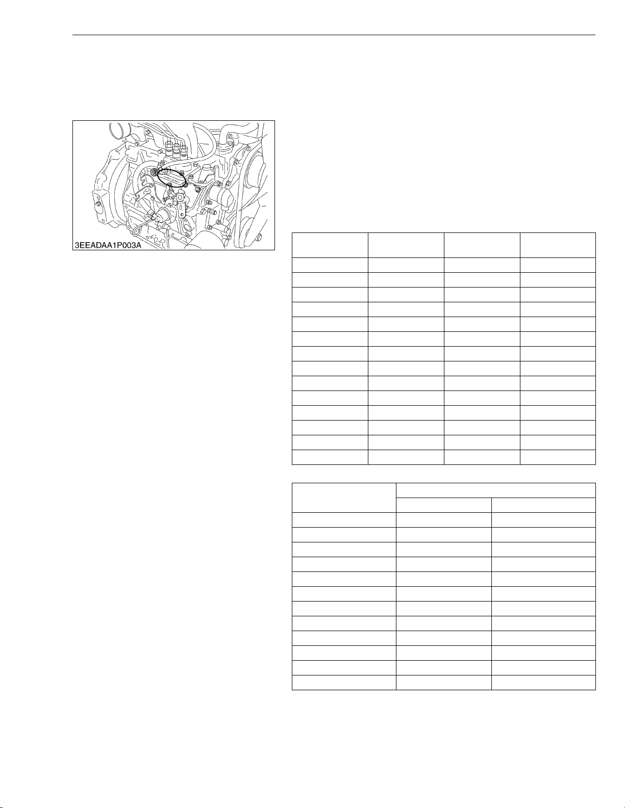
Q Engine Serial Number
The engine serial number is an identified number for the engine.
It is marked after the engine model number.
It indicates month and year of manufacture as follows.
• Year of manufacture
Alphabet or
Number
• Month of manufacture
January A0001 ~ A9999 B0001 ~
February C0001 ~ C9999 D0001 ~
March E0001 ~ E9999 F0001 ~
April G0001 ~ G9999 H0001 ~
May J0001 ~ J9999 K0001 ~
June L0001 ~ L9999 M0001 ~
July N0001 ~ N9999 P0001 ~
August Q0001 ~ Q9999 R0001 ~
September S0001 ~ S9999 T0001 ~
October U0001 ~ U9999 V0001 ~
November W0001 ~ W9999 X0001 ~
December Y0001 ~ Y9999 Z0001 ~
e.g. D1803-1A0001
“1” indicates 2001 and “A” indicates January.
So, 1A indicates that the engine was manufactured on January,
2001.
DIESEL ENGINE
Year
1 2001 F 2015
2 2002 G 2016
3 2003 H 2017
4 2004 J 2018
5 2005 K 2019
6 2006 L 2020
7 2007 M 2021
8 2008 N 2022
9 2009 P 2023
A 2010 R 2024
B 2011 S 2025
C 2012 T 2026
D 2013 V 2027
E 2014
Month
0001 ~ 9999 10000 ~
Alphabet or
Number
Engine Serial Number
Yea r
W1010477
S-1
Page 23
03-M-DI Series, WSM
KiSC issued 10, 2009 A
(2) Cylinder Number
DIESEL ENGINE
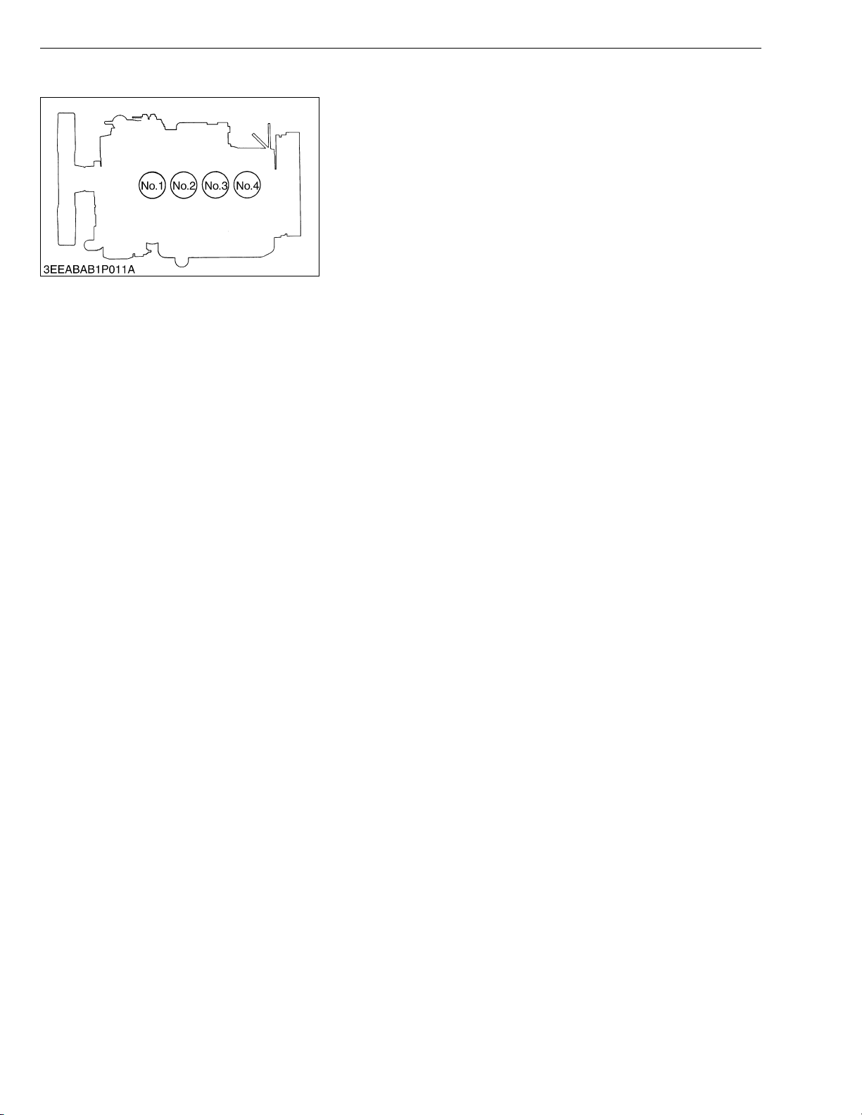
The cylinder numbers of 03-M-DI Series diesel engine are
designated as shown in the figure.
The sequence of cylinder numbers is given as No.1, No.2, No.3
and No.4 starting from the gear case side.
W1011077
S-2
Page 24
03-M-DI Series, WSM
KiSC issued 10, 2009 A
[2] GENERAL PRECAUTION
DIESEL ENGINE
• During disassembly, carefully arrange removed parts in a clean
area to prevent confusion later. Screws, bolts and nuts should be
replaced in their original position to prevent reassembly errors.
• When special tools are required, use KUBOTA genuine special
tools. Special tools which are not frequently used should be
made according to the drawings provided.
• Before disassembling or servicing live wires, make sure to
always disconnect the grounding cable from the battery first.
• Remove oil and dirt from parts before measuring.
• Use only KUBOTA genuine parts for parts replacement to
maintain engine performance and to ensure safety.
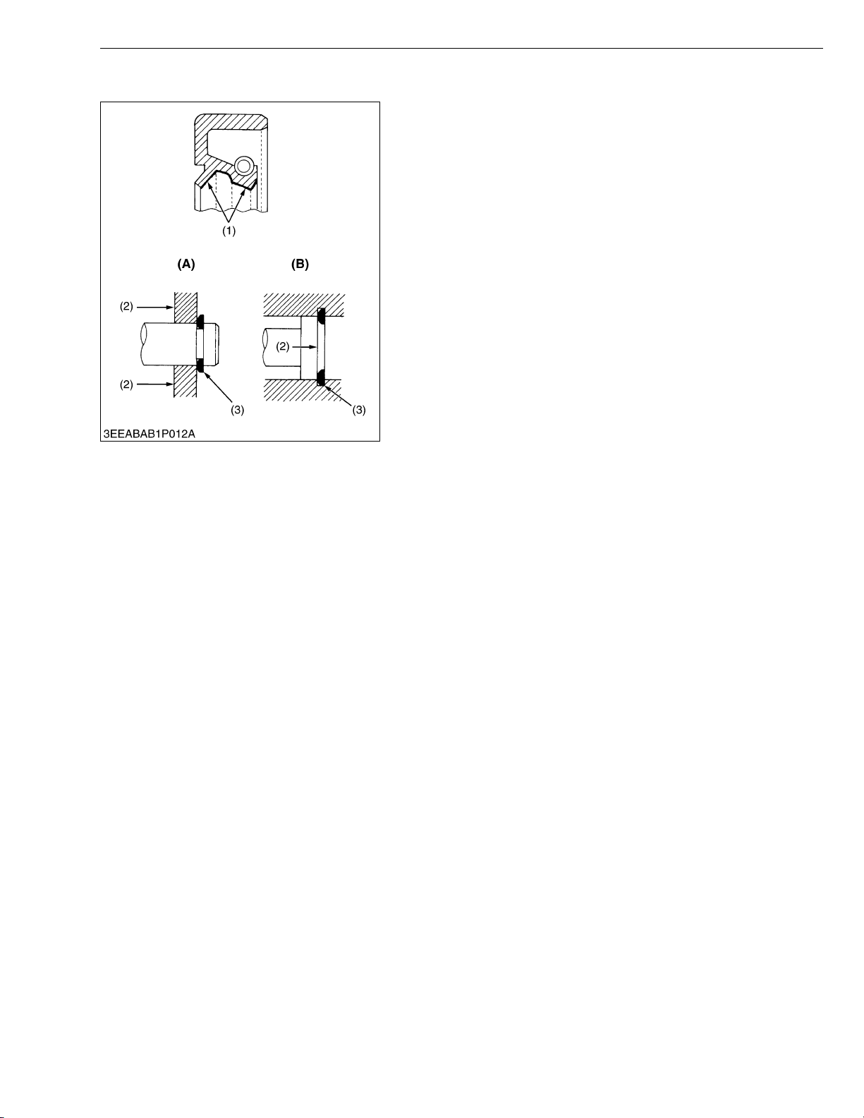
• Gaskets and O-rings must be replaced during reassembly.
Apply grease to new O-rings or oil seals before assembling.
• When reassembling external or internal snap rings, position them
so that the sharp edge faces against the direction from which
force is applied.
• Be sure to perform run-in the serviced or reassembled engine.
Do not attempt to give heavy load at once, or serious damage
may result to the engine.
(1) Grease
(2) Force
(3) Place the Sharp Edge against the
Direction of Force
(A) External Snap Ring
(B) Internal Snap Ring
W1011734
S-3
Page 25

03-M-DI Series, WSM
KiSC issued 10, 2009 A
DIESEL ENGINE
[3] TIGHTENING TORQUES
Screws, bolts and nuts must be tightened to the specified torque using a torque wrench, several screws, bolts and
nuts such as those used on the cylinder head must be tightened in proper sequence and the proper torque.
(1) Tightening Torques for Special Use Screws, Bolts and Nuts
NOTEQ
• In removing and applying the screws, bolts and nuts marked with “*”, a pneumatic wrench or similar
pneumatic tool, if employed, must be used with enough care not to get them seized.
• For “*” marked screws, bolts and nuts on the table, apply engine oil to their threads and seats before
tightening.
• The letter “M” in Size x Pitch means that the screw, bolt or nut dimension stands for metric. The size is
the nominal outside diameter in mm of the threads. The pitch is the nominal distance in mm between two
threads.
Item Size x Pitch N·m kgf·m ft-lbs
Cylinder head cover screw
* Cylinder head screw
* Main bearing case screw 1
* Main bearing case screw 2
* Flywheel screw
* Connecting rod screw
* Rocker arm bracket screw
* Idle gear shaft screw
Fan drive pulley mounting nut
* Bearing case cover screw
Glow plug
Nozzle holder clamp screw
Oil Switch taper screw
Injection pipe retaining nut
Overflow pipe assembly retaining screw
Camshaft set screw
Hi-idling body
M6 × 1.0
M11 × 1.25
M9 × 1.25
M10 × 1.25
M12 × 1.25
M8 × 1.0
M8 × 1.25
M8 × 1.25
–
M8 × 1.25
M10 × 1.25
–
PT 1/8
M12 × 1.5
–
M8 × 1.25
–
6.9 to 11.3
93.1 to 98.0
46.1 to 50.9
68.6 to 73.5
98.0 to 107.8
44.1 to 49.0
23.5 to 27.5
23.5 to 27.5
137.3 to 156.9
23.5 to 27.5
19.6 to 24.5
25.5 to 29.4
14.7 to 19.6
14.7 to 24.5
9.8 to 11.3
23.5 to 27.5
44.1 to 49.0
0.7 to 1.15
9.5 to 10.0
4.7 to 5.2
7.0 to 7.5
10.0 to 11.0
4.5 to 5.0
2.4 to 2.8
2.4 to 2.8
14.0 to 16.0
2.4 to 2.8
2.0 to 2.5
2.6 to 3.0
1.5 to 2.0
1.5 to 2.5
1.0 to 1.15
2.4 to 2.8
4.5 to 5.0
5.1 to 8.32
68.7 to 72.3
34.0 to 37.6
50.6 to 54.2
72.3 to 79.5
32.5 to 36.2
17.4 to 20.3
17.4 to 20.3
101.3 to 115.7
17.4 to 20.3
14.5 to 18.1
18.8 to 21.7
10.8 to 14.5
10.8 to 18.1
7.2 to 8.3
17.4 to 20.3
32.6 to 36.3
W1013236
(2) Tightening Torques for General Use Screws, Bolts and Nuts
Grade
Nominal Unit
Diameter
M6 7.9 to 9.3 0.80 to 0.95 5.8 to 6.9 9.8 to 11.3 1.00 to 1.15 7.23 to 8.32
M8 17.7 to 20.6 1.8 to 2.1 13.0 to 15.2 23.5 to 27.5 2.4 to 2.8 17.4 to 20.3
M10 39.2 to 45.1 4.0 to 4.6 28.9 to 33.3 48.1 to 55.9 4.9 to 5.7 35.4 to 41.2
M12 62.8 to 72.6 6.4 to 7.4 46.3 to 53.5 77.5 to 90.2 7.9 to 9.2 57.1 to 66.5
Screw and bolt material grades are shown by numbers punched on the screw and bolt heads. Prior to
tightening, be sure to check out the numbers as shown below.
Punched number Screw and bolt material grade
None or 4 Standard screw and bolt SS400, S20C
7 Special screw and bolt S43C, S48C (Refined)
Standard Screw and Bolt
Special Screw and Bolt
N·m kgf·m ft-lbs N·m kgf·m ft-lbs
W10371750
W1012705
S-4
Page 26

03-M-DI Series, WSM
KiSC issued 10, 2009 A
[4] TROUBLESHOOTING
DIESEL ENGINE
Symptom Probable Cause Solution
Engine Does Not
Start
• No fuel
• Air in the fuel system
• Water in the fuel system
Replenish fuel
Vent air
Change fuel and
repair or replace fuel
system
• Fuel pipe clogged
• Fuel filter clogged
• Excessively high viscosity of fuel or engine oil
at low temperature
• Fuel with low cetane number
• Fuel leak due to loose injection pipe retaining
Clean
Clean or change
Use specified fuel or
engine oil
Use specified fuel
Tighten retaining nut
nut
• Incorrect injection timing
• Fuel camshaft worn
• Injection nozzle clogged
• Injection pump malfunctioning
• Seizure of crankshaft, camshaft, piston,
Adjust
Replace
Replace
Replace
Repair or replace
cylinder or bearing
• Compression leak from cylinder
Replace head
gasket, tighten
cylinder head screw,
glow plug and nozzle
holder
• Improper valve timing
Correct or replace
timing gear
• Piston ring and cylinder worn
• Excessive valve clearance
Replace
Adjust
Reference
Page
–
S-20
S-20, 21,
25
S-20
S-21, 25
–
–
S-44
S-86
S-54
S-88
S-49
–
–
S-53
S-42, 56,
57, 71, 72,
79
S-31
(Starter Does Not
Run)
Engine Revolution Is
Not Smooth
• Battery discharged
• Starter malfunctioning
• Key switch malfunctioning
• Starter auto reduction unit defective
• Wiring disconnected
• Fuel filter clogged or dirty
• Air cleaner clogged
• Fuel leak due to loose injection pipe retaining
nut
• Injection pump malfunctioning
• Incorrect nozzle injection pressure
• Injection nozzle stuck or clogged
• Governor malfunctioning
• Bearing worn out
• Shaft bent
• Fin or other part damaged due to foreign
matters
Charge
Repair or replace
Repair or replace
Replace
Connect
Clean or change
Clean or change
Tighten retaining nut
Replace
Replace
Replace
Repair
Replace the
turbocharger
assembly
Replace the
turbocharger
assembly
Replace the
turbocharger
assembly
S-29
S-89, 93,
96
–
S-92, 100
S-100
S-21, 25
S-21
S-44
S-49
S-88
S-88
S-50, 54
S-101
S-101
S-101
W1014322
S-5
Page 27

03-M-DI Series, WSM
KiSC issued 10, 2009 A
DIESEL ENGINE
Symptom Probable Cause Solution
Either White or Blue
Exhaust Gas Is
Observed
• Excessive engine oil
• Piston ring and liner worn or stuck
• Incorrect injection timing
• Deficient compression
Reduce to specified
level
Repair or replace
Adjust
Check the cylinder
compression
pressure and top
clearance
Oil Leak into Exhaust
Pipe or Suction Pipe
• Waste oil pipe clogged or deformed
• Piston ring seal faulty
Repair or replace
Replace the
turbocharger
assembly
Either Black or Dark
Gray Exhaust Gas Is
Observed
Deficient Output • Incorrect injection timing
• Overload
• Low grade fuel used
• Fuel filter clogged
• Air cleaner clogged
• Deficient nozzle injection
• Engine’s moving parts seem to be seizing
• Injection pump malfunctioning
• Deficient nozzle injection
• Compression leak
Lessen load
Use specified fuel
Clean or change
Clean or change
Replace nozzle
Adjust
Repair or replace
Replace
Replace nozzle
Check the
compression
pressure and repair
• Gas leak from exhaust system
• Air leak from compressor discharge side
• Air cleaner dirty or clogged
• Compressor wheel turning heavily
Repair or replace
Repair or replace
Clean or replace
Replace the
turbocharger
assembly
Excessive Lubricant
Oil Consumption
• Piston ring’s gap facing the same direction
• Oil ring worn or stuck
• Piston ring groove worn
• Valve stem and valve guide worn
• Crankshaft bearing, and crank pin bearing
Shift ring gap
direction
Replace
Replace piston
Replace
Replace
worn
Fuel Mixed into
Lubricant Oil
Water Mixed into
Lubricant Oil
• Oil leaking due to defective seals or packing
• Injection pump’s plunger worn
• Deficient nozzle injection
• Injection pump broken
• Head gasket defective
• Cylinder block or cylinder head flawed
Replace
Replace injection
pump
Replace nozzle
Replace
Replace
Replace
Reference
Page
S-19
S-42, 56,
57, 71, 72,
79
S-86
S-42
–
S-101
–
–
S-21, 25
S-21
S-88
S-86
–
S-49
S-88
S-42
S-101
S-101
S-24
S-101
S-56
S-56, 71,
72
S-56, 71,
72
S-48, 62,
63
–
–
S-49
S-88
S-49
S-46, 47
S-46, 61
W1014322
S-6
Page 28

03-M-DI Series, WSM
KiSC issued 10, 2009 A
DIESEL ENGINE
Symptom Probable Cause Solution
Low Oil Pressure • Engine oil insufficient
• Oil strainer clogged
• Relief valve stuck with dirt
• Relief valve spring weaken or broken
• Excessive oil clearance of crankshaft bearing
• Excessive oil clearance of crankpin bearing
• Excessive oil clearance of rocker arm
• Oil passage clogged
• Different type of oil
Replenish
Clean
Clean
Replace
Replace
Replace
Replace
Clean
Use specified type of
oil
• Oil pump defective
High Oil Pressure • Different type of oil
Repair or replace
Use specified type of
oil
• Relief valve defective
Engine Overheated • Engine oil insufficient
• Fan belt broken or elongated
• Coolant insufficient
• Radiator net and radiator fin clogged with
Replace
Replenish
Replace or adjust
Replenish
Clean
dust
Battery Quickly
Discharge
• Inside of radiator corroded
• Coolant flow route corroded
• Radiator cap defective
• Overload running
• Head gasket defective
• Incorrect injection timing
• Unsuitable fuel used
• Battery electrolyte insufficient
• Fan belt slips
Clean or replace
Clean or replace
Replace
Loosen load
Replace
Adjust
Use specified fuel
Replenish distilled
water and charge
Adjust belt tension or
change
• Wiring disconnected
• Rectifier defective
• Alternator defective
Connect
Replace
Replace
Reference
Page
S-19
S-55
–
–
S-60, 75,
76, 77, 78
S-56, 74
S-45, 65
–
S-23
S-54, 81,
82
S-23
–
S-19
S-22, 28
S-19
–
S-26
–
S-84
–
S-46, 47
S-86
–
S-21, 29
S-22, 28
S-100
S-93, 99
S-93
• Battery defective
S-7
Change
–
W1014322
Page 29

03-M-DI Series, WSM
KiSC issued 10, 2009 A
DIESEL ENGINE
[5] SERVICING SPECIFICATIONS
ENGINE BODY
Item Factory Specification Allowable Limit
Cylinder Head Surface Flatness – 0.05 mm / 500 mm
0.0020 in. /
19.69 in.
Compression Pressure
(When Cranking with Starting Motor)
2.94 to 3.24 MPa /
290 min
30 to 33 kgf/cm
290 min
427 to 469 psi /
290 min
-1
(rpm)
-1
(rpm)
-1
(rpm)
2
/
2.35 MPa /
290 min
24 kgf/cm
290 min
341 psi /
290 min
-1
(rpm)
-1
(rpm)
-1
(rpm)
2
/
Difference among Cylinders
–
Top Clearance 0.60 to 0.70 mm
0.0236 to 0.0276 in.
Valve Clearance (When Cold) 0.18 to 0.22 mm
0.0071 to 0.0087 in.
Valve Seat Width (Intake)
2.12 mm
0.0835 in.
Width (Exhaust)
2.12 mm
0.0835 in.
Valve Seat Angle (Intake)
1.047 rad
60 °
Angle (Exhaust)
0.785 rad
45 °
Valve Face Angle (Intake)
1.047 rad
60 °
Angle (Exhaust)
0.785 rad
45 °
Valve Stem to Valve Guide
Clearance
0.040 to 0.070 mm
0.0016 to 0.0028 in.
10 % or less
–
–
–
–
–
–
–
–
0.1 mm
0.0039 in.
Valve Stem
Valve Guide
Valve Recessing Protrusion
O.D.
I.D.
Recessing
S-8
7.960 to 7.975 mm
0.31339 to 0.31398 in.
8.015 to 8.030 mm
0.31555 to 0.31614 in.
0.65 mm
0.026 in.
to
0.85 mm
0.033 in.
–
–
–
1.20 mm
0.0472 in.
W1013874
Page 30

03-M-DI Series, WSM
KiSC issued 10, 2009 A
ENGINE BODY (Continued)
Item Factory Specification Allowable Limit
Valve Timing (Intake Valve) Open
0.16 rad (9 °)
before T.D.C.
DIESEL ENGINE
–
Close
0.79 rad (45 °)
–
after B.D.C.
Valve Timing (Exhaust Valve) Open
0.87 rad (50 °)
–
before B.D.C.
Close
0.21 rad (12 °)
–
after T.D.C.
Valve Spring Free Length
Setting Load /
Setting Length
Tilt
41.7 to 42.2 mm
1.6417 to 1.6614 in.
117.6 N / 35.0 mm
12.0 kgf / 35.0 mm
26.4 lbs / 1.3780 in.
–
41.2 mm
1.6220 in.
100.0 N / 35.0 mm
10.2 kgf / 35.0 mm
22.5 lbs /1.3780 in.
1.0 mm
0.039 in.
Rocker Arm Shaft to Rocker Arm
Rocker Arm Shaft
Clearance
O.D.
0.016 to 0.045 mm
0.00063 to 0.00177 in.
13.973 to 13.984 mm
0.1 mm
0.0039 in.
–
0.55012 to 0.55055 in.
Rocker Arm
I.D.
14.000 to 14.018 mm
–
0.55118 to 0.55189 in.
Push Rod Alignment – 0.25 mm
0.0098 in.
Tappet to Tappet Guide
Clearance
0.020 to 0.062 mm
0.00079 to 0.00244 in.
0.07 mm
0.0028 in.
Tappet
Tappet Guide
O.D.
I.D.
S-9
23.959 to 23.980 mm
0.94327 to 0.94410 in.
24.000 to 24.021 mm
0.94488 to 0.94571 in.
–
–
W1013874
Page 31

03-M-DI Series, WSM
KiSC issued 10, 2009 A
ENGINE BODY (Continued)
Timing Gear
Crank Gear to Idle Gear
DIESEL ENGINE
Item Factory Specification Allowable Limit
Backlash
0.0415 to 0.1122 mm
0.00163 to 0.00442 in.
0.15 mm
0.0059 in.
Idle Gear to Cam Gear
Idle Gear to Injection Pump Gear
Crank Gear to Oil Pump Gear
Idle Gear to Balancer Gear
(Balancer Model Only)
Backlash
Backlash
Backlash
Backlash
(Intake side)
Backlash
(Exhaust side)
Idle Gear Side Clearance 0.12 to 0.48 mm
Idle Gear Shaft to Idle Gear Bushing
Idle Gear Shaft
Clearance
O.D.
0.0415 to 0.1154 mm
0.00163 to 0.00454 in.
0.0415 to 0.1154 mm
0.00163 to 0.00454 in.
0.0415 to 0.1090 mm
0.00163 to 0.00429 in.
0.0350 to 0.1160 mm
0.00138 to 0.00457 in.
0.0350 to 0.1160 mm
0.00138 to 0.00457 in.
0.0047 to 0.0189 in.
0.025 to 0.066 mm
0.00098 to 0.00260 in.
37.959 to 37.975 mm
0.15 mm
0.0059 in.
0.15 mm
0.0059 in.
0.15 mm
0.0059 in.
0.15 mm
0.0059 in.
0.15 mm
0.0059 in.
0.9 mm
0.0354 in.
0.1 mm
0.0039 in.
–
1.49445 to 1.49508 in.
Idle Gear Bushing
I.D.
38.000 to 38.025 mm
–
1.49606 to 1.49705 in.
Camshaft Side Clearance 0.07 to 0.22 mm
0.0028 to 0.0087 in.
0.3 mm
0.0118 in.
Camshaft Alignment – 0.01 mm
0.0004 in.
Cam Height
(Intake / Exhaust)
Camshaft Journal to Cylinder Block Bore
Clearance
33.90 mm
1.3346 in.
0.050 to 0.091 mm
0.0020 to 0.0036 in.
33.85 mm
1.3327 in.
0.15 mm
0.0059 in.
Camshaft Journal
Cylinder Block Bore
Balancer Shaft
(Balancer Model Only)
Balancer Shaft Journal 1 to Balancer Shaft
Bearing 1 (Balancer Model Only)
Balancer Shaft Journal 1
Balancer Shaft Bearing 1
O.D.
39.934 to 39.950 mm
1.57221 to 1.57284 in.
I.D.
40.000 to 40.025 mm
1.57480 to 1.57579 in.
Side Clearance 0.07 to 0.22 mm
0.0028 to 0.0087 in.
Clearance
0.030 to 0.111 mm
0.00118 to 0.00437 in.
O.D.
43.934 to 43.950 mm
1.72968 to 1.73031 in.
I.D.
43.980 to 44.045 mm
1.73149 to 1.73405 in.
S-10
–
–
0.3 mm
0.0118 in.
0.2 mm
0.0079 in.
–
–
W1013874
Page 32

03-M-DI Series, WSM
KiSC issued 10, 2009 A
ENGINE BODY (Continued)
Item Factory Specification Allowable Limit
Balancer Shaft Journal 2 to Balancer Shaft
Bearing 2 (Balancer Model Only)
Clearance
0.030 to 0.111 mm
0.00118 to 0.00437 in.
DIESEL ENGINE
0.2 mm
0.0079 in.
Balancer Shaft Journal 2
O.D.
41.934 to 41.950 mm
1.65094 to 1.65157 in.
Balancer Shaft Bearing 2
I.D.
41.980 to 42.045 mm
1.65275 to 1.65531 in.
Balancer Shaft Journal 3 to Balancer Shaft
Bearing 3 (Balancer Model Only)
Balancer Shaft Journal 3
Clearance
O.D.
0.020 to 0.094 mm
0.00079 to 0.00370 in.
21.947 to 21.960 mm
0.86405 to 0.86456 in.
Balancer Shaft Bearing 3
I.D.
21.980 to 22.041 mm
0.86535 to 0.86775 in.
Piston Pin Bore I.D. 25.000 to 25.013 mm
0.98425 to 0.98476 in.
Top Ring to Ring Groove D1703-M-DI
D1803-M-DI
Clearance 0.050 to 0.090 mm
0.0020 to 0.0035 in.
V2203-M-DI
V2403-M-DI
Second Ring to Ring
Groove
D1503-M-DI
D1503-M-DI-T
D1703-M-DI
D1803-M-DI
Clearance 0.093 to 0.128 mm
0.0037 to 0.0050 in.
0.050 to 0.090 mm
0.0020 to 0.0035 in.
V2203-M-DI
V2403-M-DI
Oil Ring to Ring Groove D1503-M-DI
D1503-M-DI-T
Clearance 0.020 to 0.060 mm
0.0008 to 0.0021 in.
–
–
0.2 mm
0.0079 in.
–
–
25.05 mm
0.9862 in.
0.2 mm
0.0079 in.
0.2 mm
0.0079 in.
0.2 mm
0.0079 in.
0.15 mm
0.0059 in.
D1703-M-DI
D1803-M-DI
0.030 to 0.070 mm
0.0012 to 0.0028 in.
V2203-M-DI
V2403-M-DI
Top Ring Ring Gap 0.20to 0.35 mm
0.0079 to 0.0138 in.
Second Ring D1503-M-DI
Ring Gap 0.30 to 0.45 mm
0.0118 to 0.0177 in.
D1503-M-DI-T
0.40 to 0.55 mm
0.0157 to 0.0217 in.
D1703-M-DI
D1803-M-DI
0.35 to 0.50 mm
0.0138 to 0.0197 in.
V2203-M-DI
V2403-M-DI
S-11
0.15 mm
0.0059 in.
1.25 mm
0.0492 in.
1.25 mm
0.0492 in.
1.25 mm
0.0492 in.
1.25 mm
0.0492 in.
W1013874
Page 33

03-M-DI Series, WSM
KiSC issued 10, 2009 A
ENGINE BODY (Continued)
Item Factory Specification Allowable Limit
Oil Ring D1503-M-DI
D1503-M-DI-T
Ring Gap 0.25 to 0.45 mm
0.0098 to 0.0177 in.
DIESEL ENGINE
1.25 mm
0.0492 in.
D1703-M-DI
D1803-M-DI
0.20 to 0.40 mm
0.0079 to 0.0157 in.
1.25 mm
0.0492 in.
V2203-M-DI
V2403-M-DI
Connecting Rod Alignment – 0.05 mm
0.0020 in.
Piston Pin to Small End Bushing
Piston Pin
Clearance
O.D.
0.014 to 0.038 mm
0.00055 to 0.00150 in.
25.002 to 25.011 mm
0.15 mm
0.0059 in.
–
0.98433 to 0.98468 in.
Small End Bushing
I.D.
25.025 to 25.040 mm
–
0.98523 to 0.98582 in.
Crankshaft Alignment – 0.02 mm
0.00079 in.
Crankshaft Journal to
Crankshaft Bearing 1
Oil Clearance
0.040 to 0.118 mm
0.00157 to 0.00465 in.
0.2 mm
0.0079 in.
(Serial No. : below
3R9999)
Crankshaft Journal
D1503-M-DI
D1503-M-DI-T
O.D.
51.921 to 51.940 mm
2.04413 to 2.04488 in.
–
D1703-M-DI
V2203-M-DI
D1803-M-DI
V2403-M-DI
Crankshaft Bearing 1
D1503-M-DI
D1503-M-DI-T
D1703-M-DI
V2203-M-DI
D1803-M-DI
V2403-M-DI
Crankshaft Journal to Crankshaft Bearing 1
(Serial No. : above 3S0001)
Crankshaft Journal
Crankshaft Bearing 1
I.D.
Oil Clearance
O.D.
I.D.
59.921 to 59.940 mm
2.35909 to 2.35984 in.
51.980 to 52.039 mm
2.04646 to 2.04878 in.
59.980 to 60.039 mm
2.36142 to 2.36374 in.
0.040 to 0.118 mm
0.00157 to 0.00465 in.
59.921 to 59.940 mm
2.35909 to 2.35984 in.
59.980 to 60.039 mm
2.36142 to 2.36374 in.
–
–
–
0.2 mm
0.0079 in.
–
–
W1029676
S-12
Page 34

03-M-DI Series, WSM
KiSC issued 10, 2009 A
ENGINE BODY (Continued)
Crankshaft Journal to
Crankshaft Bearing 2
(Serial No. : below
3R9999)
Crankshaft Journal
DIESEL ENGINE
Item Factory Specification Allowable Limit
D1503-M-DI
D1503-M-DI-T
Oil Clearance
O.D.
0.040 to 0.104 mm
0.00157 to 0.00409 in.
51.921 to 51.940 mm
2.04413 to 2.04488 in.
0.2 mm
0.0079 in.
–
D1703-M-DI
V2203-M-DI
D1803-M-DI
V2403-M-DI
Crankshaft Bearing 2
D1503-M-DI
D1503-M-DI-T
D1703-M-DI
V2203-M-DI
D1803-M-DI
V2403-M-DI
Crankshaft Journal to Crankshaft Bearing 2
(Serial No. : above 3S0001)
Crankshaft Journal
Crankshaft Bearing 2
Crankpin to Crankpin Bearing
Crankpin
I.D.
Oil Clearance
O.D.
I.D.
Oil Clearance
O.D.
59.921 to 59.940 mm
2.35909 to 2.35984 in.
51.980 to 52.025 mm
2.04646 to 2.04823 in.
59.980 to 60.025 mm
2.36142 to 2.36318 in.
0.040 to 0.104 mm
0.00157 to 0.00409 in.
59.921 to 59.940 mm
2.35909 to 2.35984 in.
59.980 to 60.025 mm
2.36142 to 2.36318 in.
0.025 to 0.087 mm
0.00098 to 0.00343 in.
46.959 to 46.975 mm
1.84878 to 1.84941 in.
–
–
–
0.2 mm
0.0079 in.
–
–
0.2 mm
0.0079 in.
–
Crankpin Bearing
I.D.
47.000 to 47.046 mm
–
1.85039 to 1.85220 in.
Crankshaft
(Serial No. : below
3R9999)
D1503-M-DI
D1503-M-DI-T
D1703-M-DI
Side Clearance 0.15 to 0.35 mm
0.0059 to 0.0138 in.
0.5 mm
0.0197 in.
V2203-M-DI
Crankshaft
(Serial No. : above 3S0001)
D1803-M-DI
V2403-M-DI
Side Clearance 0.15 to 0.31 mm
0.15 to 0.31 mm
0.0059 to 0.0122 in.
0.0059 to 0.0122 in.
0.5 mm
0.0197 in.
0.5 mm
0.0197 in.
Crankshaft Sleeve Wear – 0.1 mm
0.0039 in.
S-13
W1013874
Page 35
03-M-DI Series, WSM
KiSC issued 10, 2009 A
ENGINE BODY (Continued)
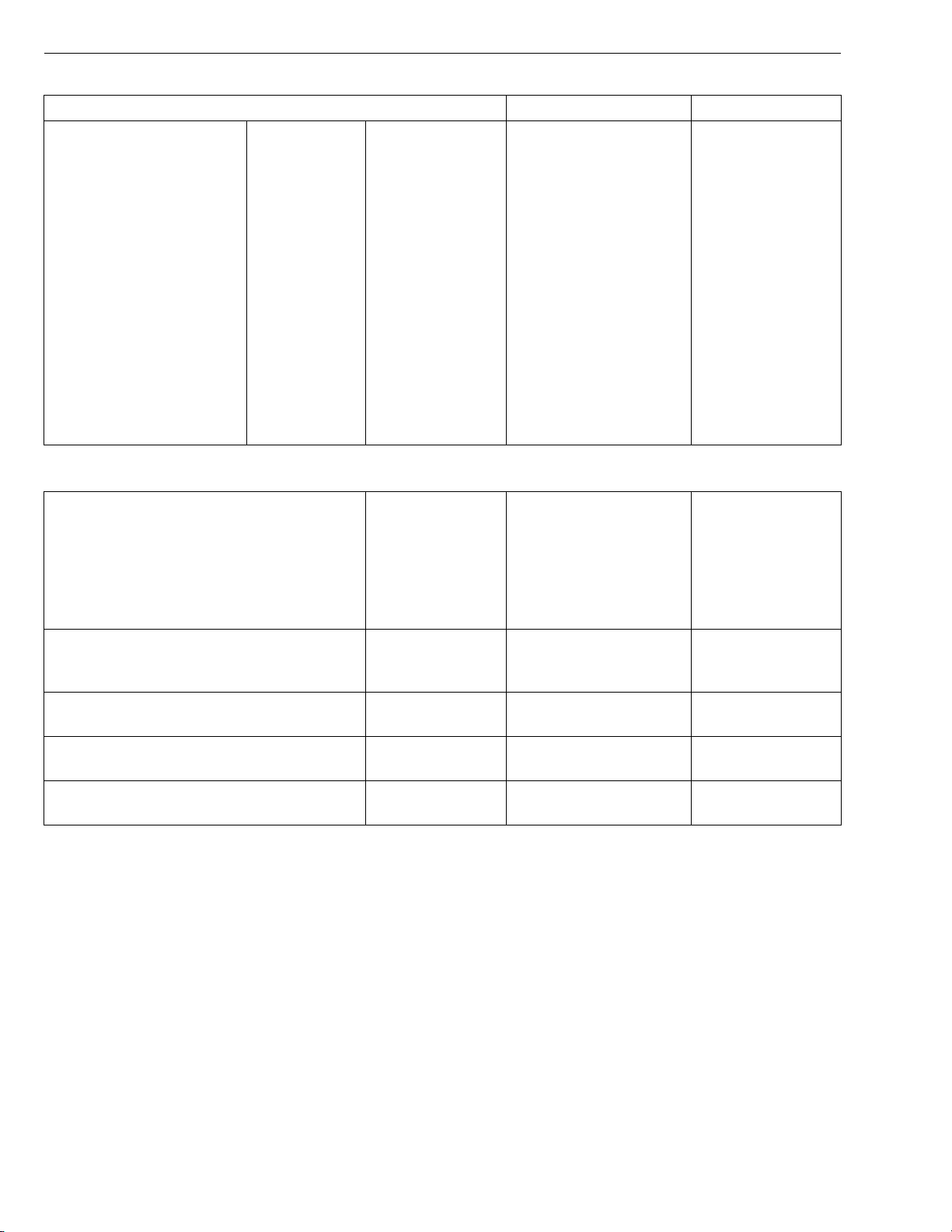
Cylinder Bore
[Standard]
DIESEL ENGINE
Item Factory Specification Allowable Limit
D1503-M-DI
D1503-M-DI-T
I.D.
83.000 to 83.022 mm
3.26772 to 3.26858 in.
83.150 mm
3.2736 in.
D1703-M-DI
D1803-M-DI
87.000 to 87.022 mm
3.42519 to 3.42606 in.
V2203-M-DI
V2403-M-DI
[Oversize]
D1503-M-DI
D1503-M-DI-T
D1703-M-DI
D1803-M-DI
I.D.
83.250 to 83.272 mm
3.27756 to 3.27843 in.
87.250 to 87.272 mm
3.43503 to 3.43590 in.
V2203-M-DI
V2403-M-DI
LUBRICATING SYSTEM
Engine Oil Pressure At Idle Speed
At Rated Speed
294 to 441 kPa
–
3.0 to 4.5 kgf/cm
42.7to 64.0 psi
Engine Oil Pressure Switch Working
Pressure
49 kPa
0.5 kgf/cm
2
7 psi
Inner Rotor to Outer Rotor Clearance 0.03 to 0.14 mm
0.0012 to 0.0055 in.
Outer Rotor to Pump Body Clearance 0.11 to 0.19 mm
0.0043 to 0.0075 in.
Inner Rotor to Cover Clearance 0.105 to 0.150 mm
0.00413 to 0.00591 in.
87.150 mm
3.4311 in.
83.400 mm
3.2835 in.
87.400 mm
3.4409 in.
W1198742
49 kPa
0.5 kgf/cm
2
7 psi
2
245 kPa
2.5 kgf/cm
2
35.6 psi
–
0.2 mm
0.0079 in.
0.25 mm
0.0098 in.
0.2 mm
0.0079 in.
W1013973
S-14
Page 36

03-M-DI Series, WSM
KiSC issued 10, 2009 A
COOLING SYSTEM
Item Factory Specification Allowable Limit
Fan Belt Tension 7.0 to 9.0 mm (0.28 to
0.35 in.) deflection at 98
N (10 kgf, 22 lbs) of
force
Thermostat Valve Opening
Temperature
69.5 to 72.5 °C
157.1 to 162.5 °F
(At Beginning)
DIESEL ENGINE
–
–
Valve Opening
Temperature
85 °C
185 °F
(Opened
Completely)
Radiator Water Tightness No leaks at
137 kPa
1.4 kgf/cm
20 psi
Radiator Cap Pressure Falling
Time
10 seconds or more for
pressure falling
from 88 to 59 kPa
from 0.9 to 0.6 kgf/cm
from 13 to 9 psi
FUEL SYSTEM
Injection Pump D1503-M-DI
D1503-M-DI-T
D1703-M-DI
D1803-M-DI
V2203-M-DI
V2403-M-DI
Injection Nozzle Injection
Injection Nozzle Valve Seat Valve Seat
Injection Timing 0.18 to 0.22 rad (10.5 to
12.5 °) before T.D.C.
0.16 to 0.19 rad (9.0 to
11.0 °) before T.D.C.
0.17 to 0.21 rad (10.0 to
12.0 °) before T.D.C.
18.6 to 20.1 MPa
Pressure
1st. stage
190 to 205 kgf/cm
2702 to 2916 psi
When the pressure is
Tightness
16.67 MPa
(170 kgf/cm
2
, 2418 psi),
the valve seat must be
fuel tightness.
–
–
2
–
2
W1013874
–
2
–
–
W1013973
S-15
Page 37

03-M-DI Series, WSM
KiSC issued 10, 2009 A
ELECTRICAL SYSTEM
Starter
Commutator
DIESEL ENGINE
Item Factory Specification Allowable Limit
D1503-M-DI
D1503-M-DI-T
O.D.
30.0 mm
1.181 in.
29.0 mm
1.142 in.
D1703-M-DI
D1803-M-DI
V2203-M-DI
Mica
Brush
Brush Holder and
Holder Support
Alternator
Stator
Rotor
V2403-M-DI
D1503-M-DI
D1503-M-DI-T
D1703-M-DI
D1803-M-DI
V2203-M-DI
V2403-M-DI
D1503-M-DI
D1503-M-DI-T
D1703-M-DI
D1803-M-DI
V2203-M-DI
V2403-M-DI
Under Cut
Length
Resistance
No-load voltage
Resistance
35.0 mm
1.378 in.
0.50 to 0.80 mm
0.0197 to 0.0315 in.
0.50 to 0.90 mm
0.0197 to 0.0354 in.
15.0 mm
0.591 in.
Infinity
More than 13.5 V
Continuity
2.9 Ω
2.1 Ω
34.0 mm
1.339 in.
0.20 mm
0.0079 in.
0.20 mm
0.0079 in.
11.0 mm
0.433 in.
–
–
–
–
–
Slip Ring
Brush
Glow Plug Resistance Approx. 1.0 Ω –
Stop Solenoid
Pulling Coil
Holding Coil
O.D.
Length
Resistance
Resistance
S-16
14.4 mm
0.567 in.
10.5 mm
0.413 in.
Approx. 0.38 Ω
Approx. 15.58 Ω
14.0 mm
0.551 in.
8.4 mm
0.331 in.
–
–
W1075692
Page 38
03-M-DI Series, WSM
KiSC issued 10, 2009 A
DIESEL ENGINE
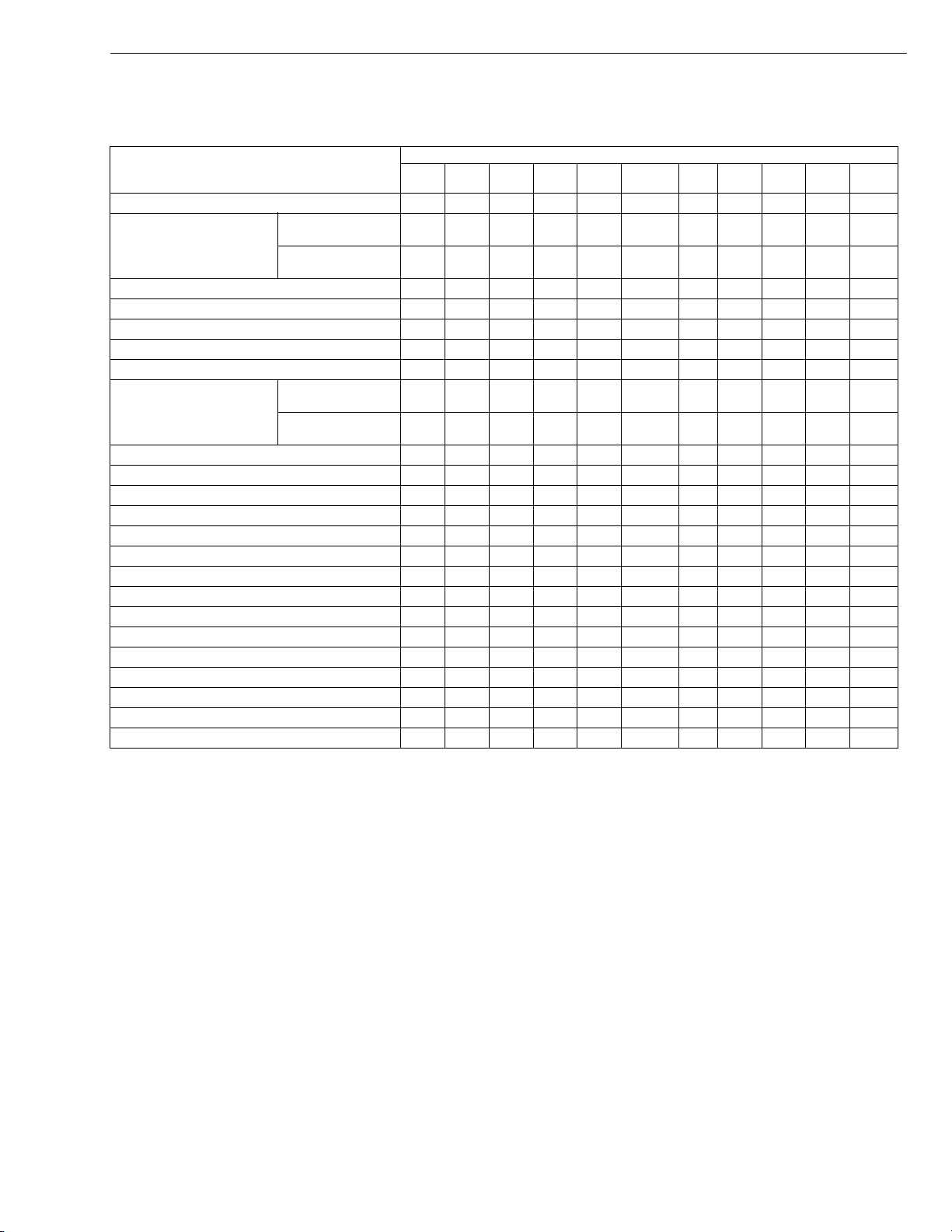
[6] MAINTENANCE CHECK LIST
To maintain long-lasting and safe engine performance, make it a rule to carry out regular inspections by following
the table below.
Item
Checking fuel pipes and clamp bands
* Changing Engine oil
(depending on the oil pan)
Cleaning air cleaner element ,
Cleaning fuel filter (Normal type)
Checking battery electrolyte level ,
Check fan belt tension and damage
Checking radiator hoses and clamp bands
* Replacing oil filter cartridge (1) Oil pandepth
Checking intake air line ,
Replacing fuel filter cartridge
Cleaning fuel tank inside
Cleaning water jacket and radiator interior
Replacing fan belt
Recharging battery ,
Replacing air cleaner element
Checking valve clearance
**Checking injection nozzle condition
Checking turbocharger
Replacing intake air line
Replacing battery ,
Replacing radiator hoses and clamp bands
Replacing fuel pipes and clamp bands
Changing radiator coolant (L.L.C.) ,
+ Change engine oil and replace oil filter cartridge after the first 50 hours of operation.
(1) Oil pan depth
(90 mm 3.54 in.)
(2) Oil pan depth
(124 mm 4.88 in.)
(90 mm 3.54 in.)
(2) Oil pandepth
(124 mm 4.88 in.)
50
100
200
hrs
hrs
,
+,
+,
,
,
+,
+,
hrs
,
400
hrs
,
* The items listed above (* marked) are registered as emission related critical parts by KUBOTA in the U.S. EPA
nonroad emission regulation. As the engine owner, you are responsible for the performance of the required
maintenance on the engine according to the above instruction.
Service Interval
500
1 or 2
hrs
months1 year
,
,
,
800
1500
hrs
,
3000
hrs2 years
,
,
,
,
W1029462
hrs
,
,
S-17
Page 39
03-M-DI Series, WSM
KiSC issued 10, 2009 A
DIESEL ENGINE
CAUTION
• When changing or inspecting, be sure to level and stop the engine.
Q NOTE
Lubricating Oil
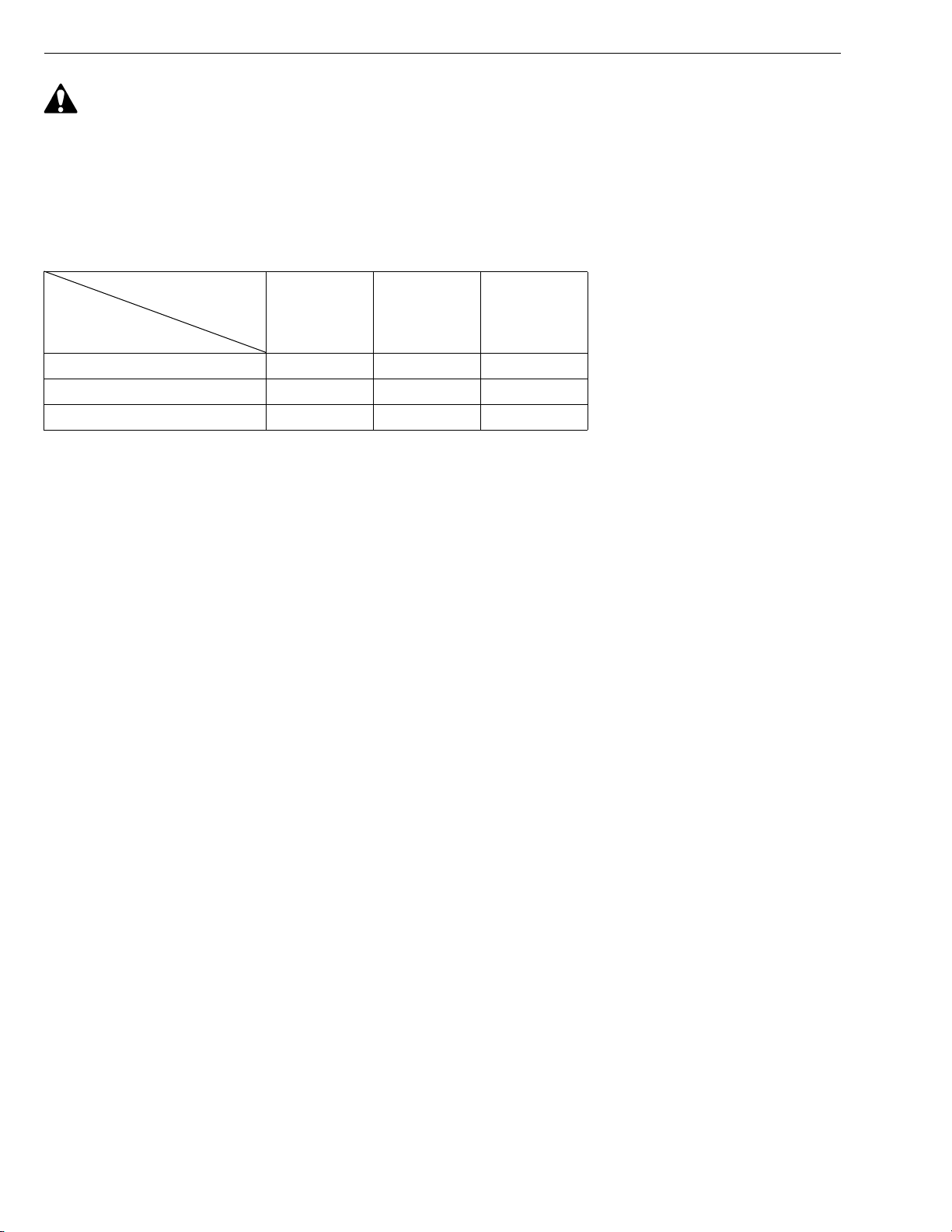
With the emission control now in effect, the CF-4 and CG-4 lubricating oils have been developed for use of a lowsulfur fuel on-road vehicle engines. When an off-road vehicle engine runs on a high-sulfur fuel, it is advisable to
employ the CF, CD or CE lubricating oil with a high total base number. If the CF-4 or CG-4 lubricating oil is used with
a high-sulfur fuel, change the lubricating oil at shorter intervals.
• Lubricating oil recommended when a low-sulfur or high-sulfur fuel is employed.
Fuel
Lubricating
Low sulfur
(0.5 % ≥)
High sulfur Remarks
oil class
CF PPTBN ≥ 10
CF-4 P X
CG-4 P X
P : Recommendable X : Not recommendable
W1035555
S-18
Page 40
03-M-DI Series, WSM
KiSC issued 10, 2009 A
[7] CHECK AND MAINTENANCE
(1) Daily Check Points
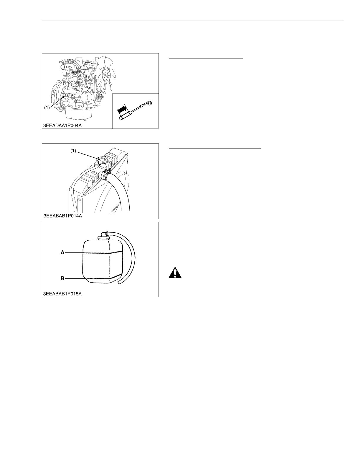
Checking Engine Oil Level
1. Level the engine.
2. To check the oil level, draw out the dipstick (1), wipe it clean,
3. If the level is too low, add new oil to the specified level.
• When using an oil of different maker or viscosity from the
(1) Dipstick
Checking and Replenish Coolant
1. Without recovery tank ;
2. If coolant level is too low, check the reason for decreasing
DIESEL ENGINE
reinsert it, and draw it out again.
Check to see that the oil level lies between the two notches.
IMPORTANTQ
previous one, drain old oil. Never mix two different types of
oil.
W1035676
Remove the radiator cap (1) and check to see that the coolant
level is just below the port.
With recovery tank :
Check to see that the coolant level lies between FULL A and
LOW B.
coolant.
Case 1) If coolant is decreasing by evaporation, replenish only
fresh, soft water.
Case 2) If coolant is decreasing by leak, replenish coolant of the
same manufacture and type in the specified mixture
ratio (fresh, soft water and L.L.C.).
If the coolant brand cannot be identified, drain out all of
the remaining coolant and refill with a totally new brand
of coolant mix. (See page S-26, 27.)
CAUTION
• Do not remove the radiator cap until coolant temperature is
below its boiling point. Then loosen the cap slightly to
relieve any excess pressure before removing the cap
completely.
IMPORTANTQ
• During filling the coolant, air must be vented from the engine
coolant passages. The air vents by jiggling the radiator
upper and lower hoses.
• Be sure to close the radiator cap securely. If the cap is loose
or improperly closed, coolant may leak out and the engine
could overheat.
• Do not use an antifreeze and scale inhibitor at the same time.
• Never mix the different type or brand of L.L.C..
(1) Radiator Cap A: FULL
B: LOW
W1035779
S-19
Page 41
03-M-DI Series, WSM
KiSC issued 10, 2009 A
(2) Check Points of Every 50 Hours
DIESEL ENGINE
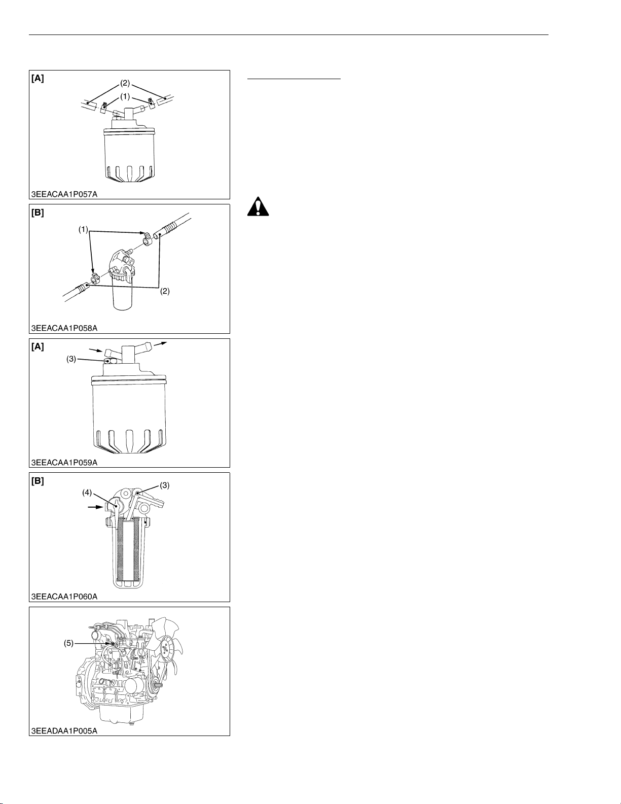
Checking Fuel Pipe
1. If the clamp (1) is loose, apply oil to the threads and securely
retighten it.
2. The fuel pipe (2) is made of rubber and ages regardless of the
period service.
Change the fuel pipe together with the clamp every two years.
3. However, if the fuel pipe and clamp are found to be damaged or
deteriorate earlier than two years, then change or remedy.
4. After the fuel pipe and the clamp have been changed, bleed the
fuel system.
CAUTION
• Stop the engine when attempting the check and change
prescribed above.
(1) Clamp
(2) Fuel Pipe
[A] Cartridge Type
[B] Normal Type
W1035921
(When bleeding fuel system)
1. Fill the tank with fuel and open the fuel cock (4). ([B] only)
2. Loosen the air vent plug (3) of the fuel filter a few turns.
3. Screw back the plug when bubbles do not come up any more.
4. Open the air vent cock (5) on top of the fuel injection pump.
5. If equipped electrical fuel feed pump, turn the key to AC position
and pump the fuel up for 10 to 15 seconds.
If equipped mechanical fuel feed pump, set the stop lever on stop
position and crank the engine for 10 to 15 seconds.
6. Close securely the air vent cock after air bleeding.
NOTEQ
• Always keep the air vent cock on the fuel injection pump
closed except when air is vented, or it may cause the engine
to stop.
(3) Air Vent Plug
(4) Fuel Cock
(5) Air Vent Cock
[A] Cartridge Type
[B] Normal Type
W1188557
S-20
Page 42
03-M-DI Series, WSM
KiSC issued 10, 2009 A
(3) Check Points of Every 100 Hours
DIESEL ENGINE
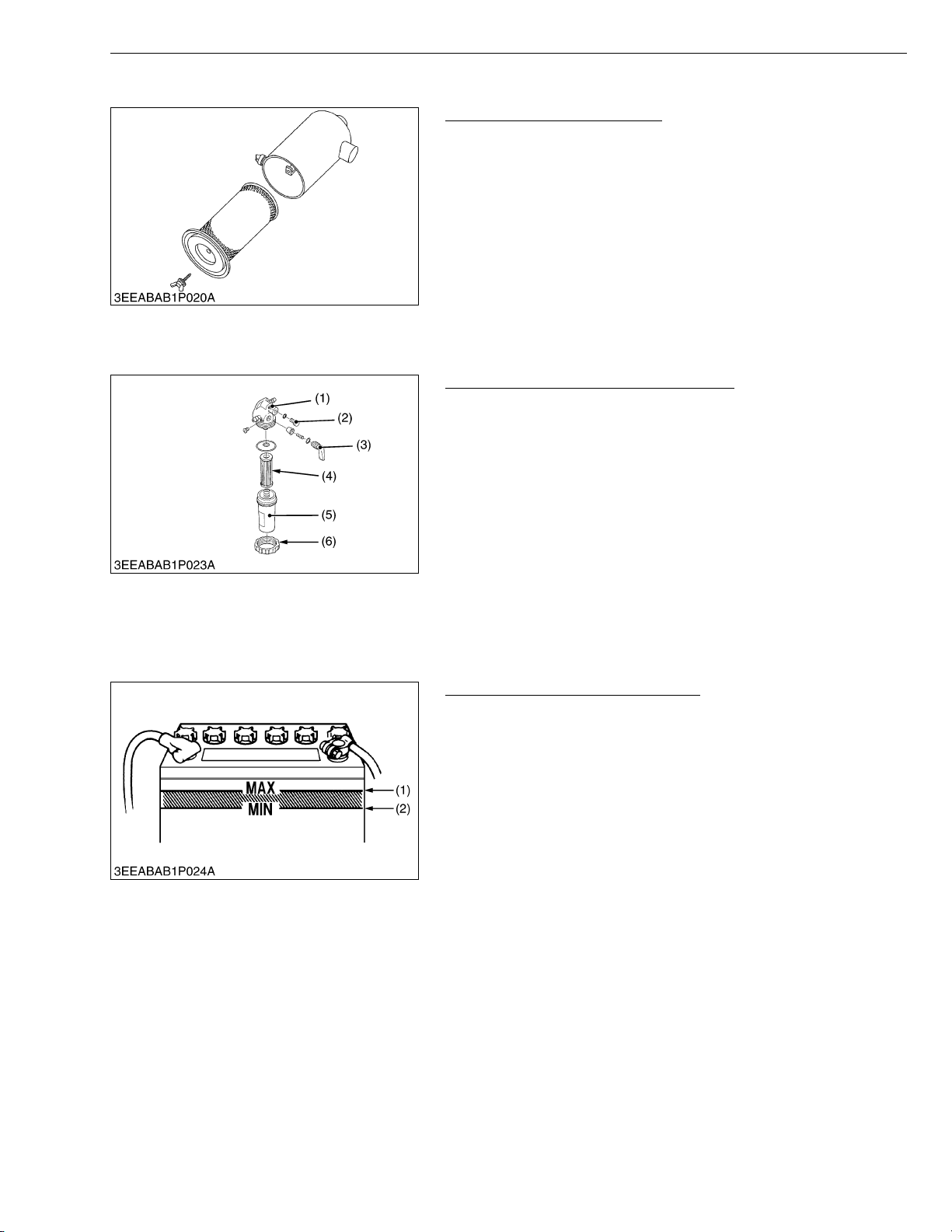
Cleaning Air Cleaner Element
1. Remove the air cleaner element.
2. Use clean dry compressed air on the inside of the element.
Pressure of compressed air must be under 205 kPa (2.1 kgf/cm
30 psi).
Maintain reasonable distance between the nozzle and the filter.
NOTEQ
• The air cleaner uses a dry element. Never apply oil to it.
• Be sure to refit the dust cup with arrow ↑ (on the rear)
upright. If the dust cup is improperly fitted, dust passes by
the dust cup and directly adheres to the element.
• Do not run the engine with filter element removed.
• Change the element once a year or every 6th cleaning.
W1045746
Cleaning Fuel Filter (Normal Type only)
1. Close the fuel cock (3).
2. Unscrew the retaining ring (6) and remove the cup (5), and rinse
the inside with kerosene.
3. Take out the element (4) and dip it in the kerosene to rinse.
4. After cleaning, reassemble the fuel filter, keeping out dust and
dirt.
5. Bleed the fuel system.
IMPORTANTQ
• If dust and dirt enter the fuel, the fuel injection pump and
injection nozzle will wear quickly. To prevent this, be sure
to clean the fuel filter cup (5) periodically.
(1) Cock Body
(2) Air Vent Plug
(3) Fuel Cock
(4) Filter Element
(5) Filter Cup
(6) Retaining Ring
W1046058
Checking Battery Electrolyte Level
1. Check the battery electrolyte level.
2. If the level is below than lower level line (2), and the distilled water
to pour level of each cell.
(1) Upper Level Line (2) Lower Level Line
W1047154
2
,
S-21
Page 43
03-M-DI Series, WSM
KiSC issued 10, 2009 A
DIESEL ENGINE
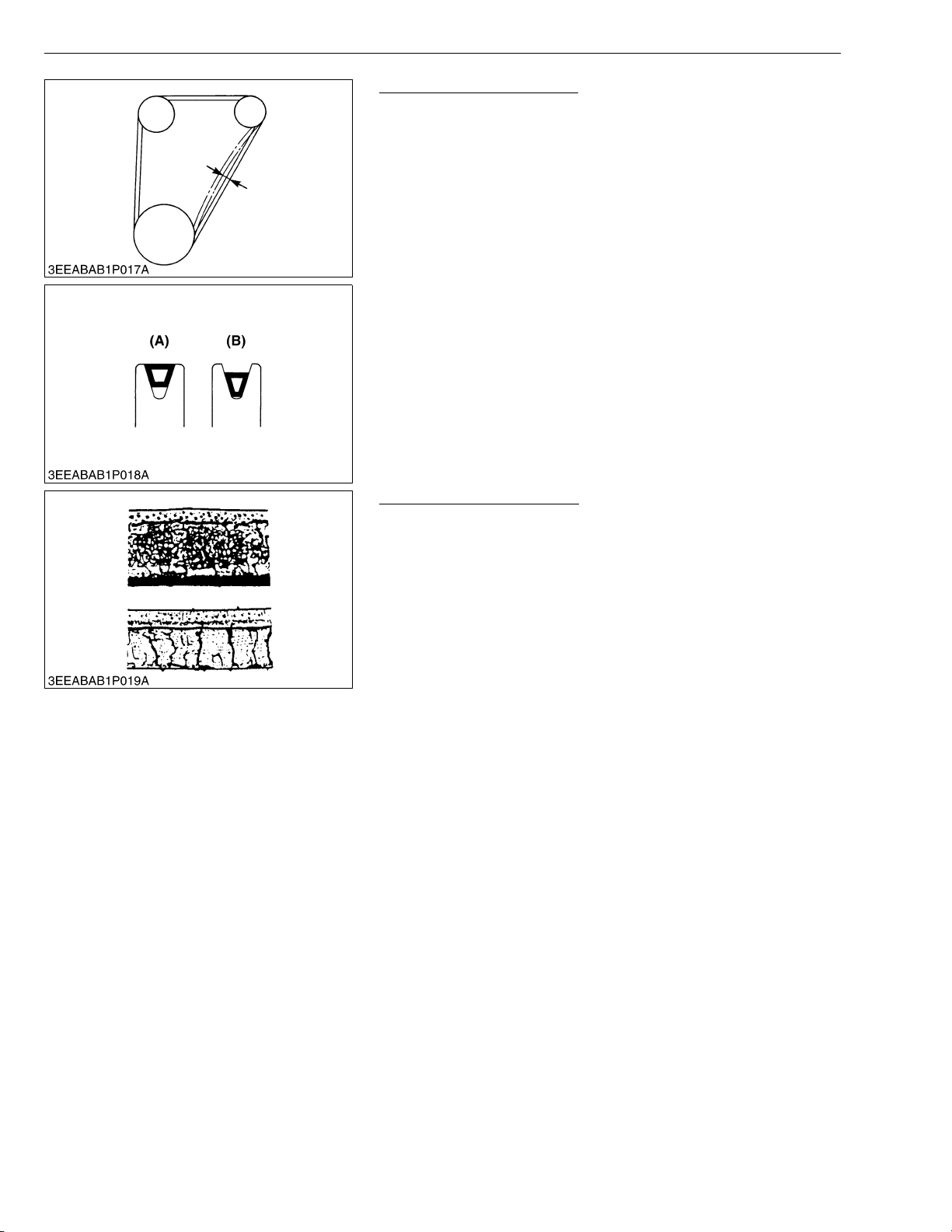
Checking Fan Belt Tension
1. Press the fan belt between fan pulley and pulley at force of 98 N
(10 kgf, 22 lbs).
Check if the fan belt deflection is 7 to 9 mm (0.28 to 0.35 in.).
2. If the deflection is not within the factory specifications, adjust with
the tension pulley adjusting bolts.
(A) Good (B) Bad
W1057138
Checking Fan Belt Damage
1. Check the fan belt for damage.
2. Check if the fan belt is worn and sunk in the pulley groove.
3. Replace the fan belt if the belt is damaged or nearly worn out and
deeply sunk in the pulley groove.
W1057475
S-22
Page 44
03-M-DI Series, WSM
KiSC issued 10, 2009 A
(4) Check Point of Every 200 Hours
DIESEL ENGINE
Changing Engine Oil (For 90 mm (3.54 in.) depth oil pan)
See page S-24.
Replacing Oil Filter Cartridge (For 90 mm (3.54 in.) depth oil
pan)
See page S-25.
W1036826
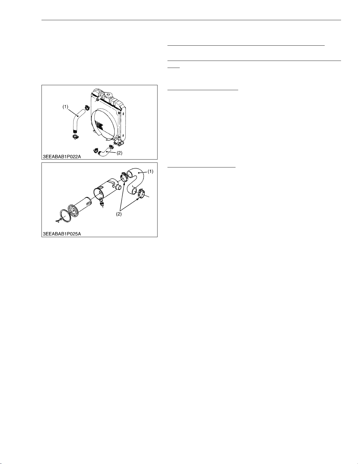
Checking Radiator Hoses
1. Check to see if the radiator hoses are properly fixed every 200
hours of operation or every six months, whichever comes first.
2. If the clamp is loose, apply oil to the threads and retighten it
securely.
3. The water pipe is made of rubber and tends to age. It must be
changed every two years. Also change the clamp and tighten it
securely.
(1) Upper Hose (2) Lower Hose
W1050147
Checking Intake Air Line
1. Check to see if the intake air hose(s) (1) are properly fixed every
200 hours of operation.
2. If the clamp (2) is loose, apply oil to the threads and retighten it
securely.
3. The intake air hose(s) (1) is made of rubber and tends to age. It
must be change every two years. Also change the clamp (2) and
tighten it securely.
IMPORTANTQ
• To prevent serious damage to the engine, keep out any dust
inside the intake air line.
(1) Intake Air Hose (2) Clamp
W1050335
S-23
Page 45
03-M-DI Series, WSM
KiSC issued 10, 2009 A
(5) Check Points of Every 400 Hours
DIESEL ENGINE
Changing Engine Oil (For 124 mm (4.88 in.) depth oil pan)
CAUTION
• Be sure to stop the engine before changing the engine oil.
1. After warming up, stop the engine.
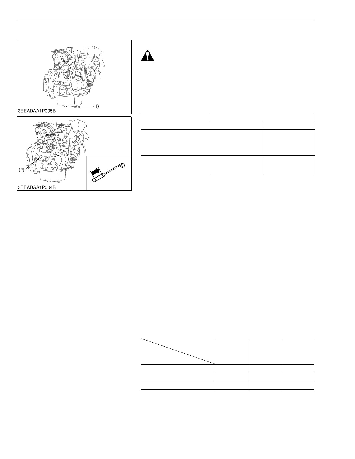
2. Place an oil pan underneath the engine.
3. Remove the drain plug (1) to drain the dirty engine oil completely.
4. Inspect the drain plug gasket. Replace it damaged.
5. Reinstall the drain plug.
6. Fill the new engine oil up to the upper mark on the dipstick (2).
Models
D1503-M-DI
D1503-M-DI-T
D1703-M-DI
D1803-M-DI
V2203-M-DI
V2403-M-DI
*90 mm (3.54 in.) oil pan depth is optional.
124 mm (4.88 in.) *90 mm (3.54 in.)
1.85 U.S.gal.
1.54 lmp.gal.
2.51 U.S.gal.
2.09 lmp.gal.
7.0 L
9.5 L
Oil pan depth
5.6 L
1.48 U.S.gal.
1.23 lmp.gal.
7.6 L
2.01 U.S.gal.
1.672 lmp.gal.
IMPORTANTQ
• When using an oil of difference maker or viscosity from the
previous one, drain an old oil completely.
• Never mix two different types of oil.
• Engine oil should be MIL-L-46152 / MIL-L-2104C or have
properties of API classification CD / CE / CF / CF-4 / CG-4.
• Use the proper SAE Engine oil according to ambient
temperature.
Above 25 °C (77 °F)..................SAE 30 or 10W-30
0 °C to 25 °C (32 °F to 77 °F)....SAE 20 or 10W-30
Below 0 °C (32 °F).....................SAE 10W or 10W-30
Q NOTE
Lubricating Oil
With the emission control now in effect, the CF-4 and CG-4
lubricating oils have been developed for use of a low-sulfur fuel onroad vehicle engines. When an off-road vehicle engine runs on a
high-sulfur fuel, it is advisable to employ the CD, CE or CF
lubricating oil with a high total base number. If the CF-4 or CG-4
lubricating oil is used with a high-sulfur fuel, change the lubricating
oil at shorter intervals.
• Lubricating oil recommended when a low-sulfur or high-
sulfur fuel is employed.
Fuel
Lubricating
oil class
CF PPTBN ≥ 10
CF-4 P X
CG-4 P X
P : Recommendable X : Not recommendable
(1) Drain Plug (2) Dipstick
Low sulfur
(0.5 % ≥)
High sulfur Remarks
W1056838
S-24
Page 46
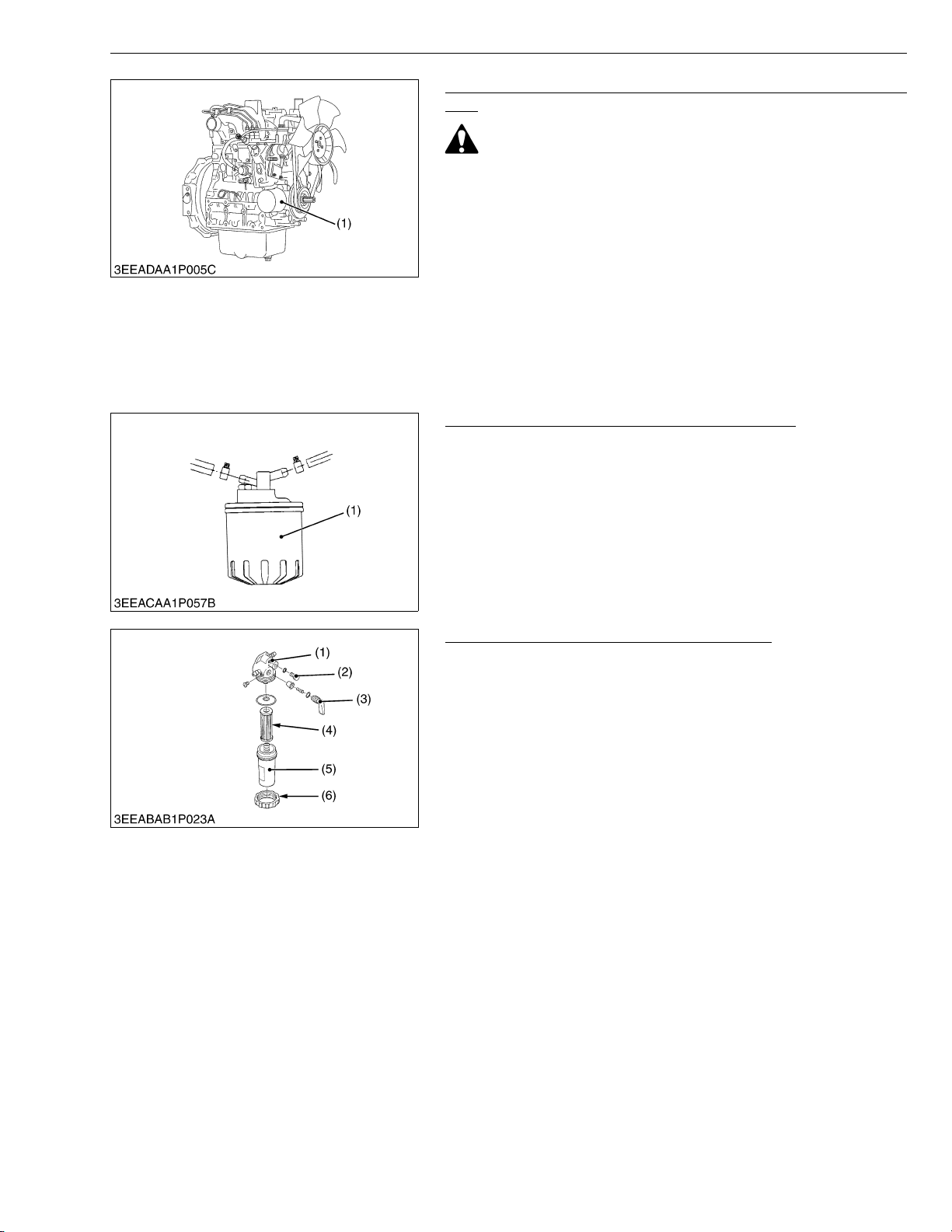
03-M-DI Series, WSM
KiSC issued 10, 2009 A
DIESEL ENGINE
Replacing Oil Filter Cartridge (For 124 mm (4.88 in.) depth oil
pan)
CAUTION
• Be sure to stop the engine before changing the engine oil
filter cartridge (1).
1. Remove the engine oil filter cartridge (1) with the filter wrench.
2. Apply engine oil slightly to the rubber gasket of new cartridge.
3. Install the new cartridge, screwing it in by hand.
4. After the cartridge has been changed, the engine oil level
normally lowers a little. Add engine oil to proper level.
IMPORTANTQ
• To prevent serious damage to the engine, replacement
engine oil filter cartridge (1) must be highly efficient. Use
only a genuine KUBOTA filter cartridge or its equivalent.
(1) Engine Oil Filter Cartridge
W1037215
Replacing Fuel Filter Cartridge (Cartridge Type)
Water and dust in fuel are collected in the filter cartridge (1). So,
change the filter cartridge (1) every 400 hours service.
1. Remove the used filter cartridge (1) with filter wrench.
2. Apply a thin film of fuel to the surface of new filter cartridge gasket
before screwing on.
3. Then tighten enough by hand.
4. Loosen the air vent plug to let the air out.
5. Start engine and check for fuel leakage.
(1) Fuel Filter Cartridge
W1050548
Replacing Fuel Filter Element (Normal Type)
1. Close the fuel cock (3).
2. Unscrew the retaining ring (6) and remove the filter cup (5), and
rinse the inside with kerosene.
3. Replace the filter element (4).
4. Reassemble the fuel filter, keeping out dust and dirt.
5. Bleed the fuel system.
(1) Cock Body
(2) Air Vent Plug
(3) Fuel Cock
(4) Filter Element
(5) Filter Cup
(6) Retaining Ring
W1220708
S-25
Page 47
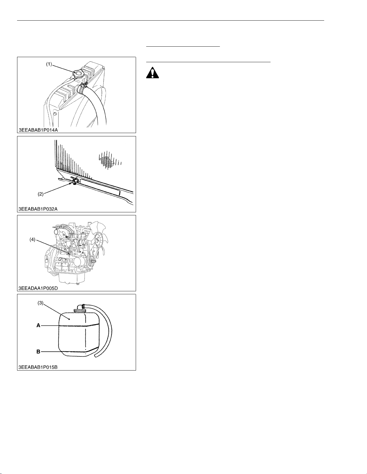
03-M-DI Series, WSM
KiSC issued 10, 2009 A
(6) Check Points of 500 Hours
DIESEL ENGINE
Cleaning Fuel Tank Inside
W1051414
Cleaning Water Jacket and Radiator Interior
CAUTION
• Do not remove the radiator cap (1) when the engine is hot.
Then loosen cap slightly to the stop to relieve any excess
pressure before removing cap completely.
1. Stop the engine and let cool down.
2. To drain the coolant, open the radiator drain plug (2) and remove
the radiator cap (1). Then radiator cap (1) must be removed to
completely drain the coolant
3. After all coolant is drained, close the drain plug (2).
4. Fill with clean water and cooling system cleaner.
5. Follow directions of the cleaner instruction.
6. After flushing, fill with clean water and anti-freeze until the coolant
level is just below the port. Install the radiator cap (1) securely.
7. Fill with coolant up to “FULL” mark on the recovery tank (3).
8. Start and operate the engine for few minutes.
9. Stop the engine and let cool. Check coolant level of recovery
tank (3) and add coolant if necessary.
IMPORTANTQ
• Do not start engine without coolant.
• Use clean, fresh, soft water and anti-freeze to fill the radiator
and recovery tank (3).
• When the anti-freeze is mixed with fresh, soft water, the antifreeze mixing ratio must be less than 50 %.
• Securely tighten radiator cap (1). If the cap is loose or
improperly fitted, water may leak out and the engine could
overheat.
(1) Radiator Cap
(2) Drain Plug
(3) Recovery Tank
(4) Drain Cock
A : Full
B : Low
W1038102
S-26
Page 48
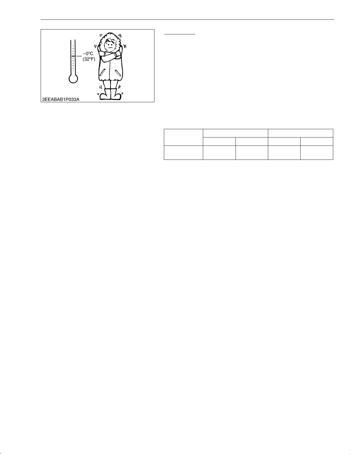
03-M-DI Series, WSM
KiSC issued 10, 2009 A
DIESEL ENGINE
Anti-Freeze
• There are two types of anti-freeze available: use the permanent
type (PT) for this engine.
• Before adding anti-freeze for the first time, clean the radiator
interior by pouring fresh, soft water and draining it a few times.
• The procedure for mixing water and anti-freeze differs according
to the make of the anti-freeze and the ambient temperature.
Basically, it should be referred to SAE J1034 standard, more
specifically also to SAE J814c.
• Mix the anti-freeze with fresh, soft water, and then fill into the
radiator.
IMPORTANTQ
• When the anti-freeze is mixed with fresh, soft water, the antifreeze mixing ratio must be less than 50 %.
Vol %
anti-freeze
40
50
* At 1.013 × 10
Freezing point Boiling point
°C °F °C °F
–24
–37
5
Pa (1.033 kgf/cm2) pressure (atmospheric). A
–12
–34
106
108
222
226
higher boiling point is obtained by using a radiator pressure cap
which permits the development of pressure within the cooling
system.
NOTEQ
• The above data represents industrial standards that
necessitate a minimum glycol content in the concentrated
anti-freeze.
• When the coolant level drops due to evaporation, add fresh,
soft water only to keep the anti-freeze mixing ratio less than
50 %. In case of leakage, add anti-freeze and fresh, soft
water in the specified mixing ratio.
• Anti-freeze absorbs moisture. Keep unused anti-freeze in a
tightly sealed container.
• Do not use radiator cleaning agents when anti-freeze has
been added to the coolant.
(Anti-freeze contains an anti-corrosive agent, which will
react with the radiator cleaning agent forming sludge which
will affect the engine parts.)
W1039218
S-27
Page 49
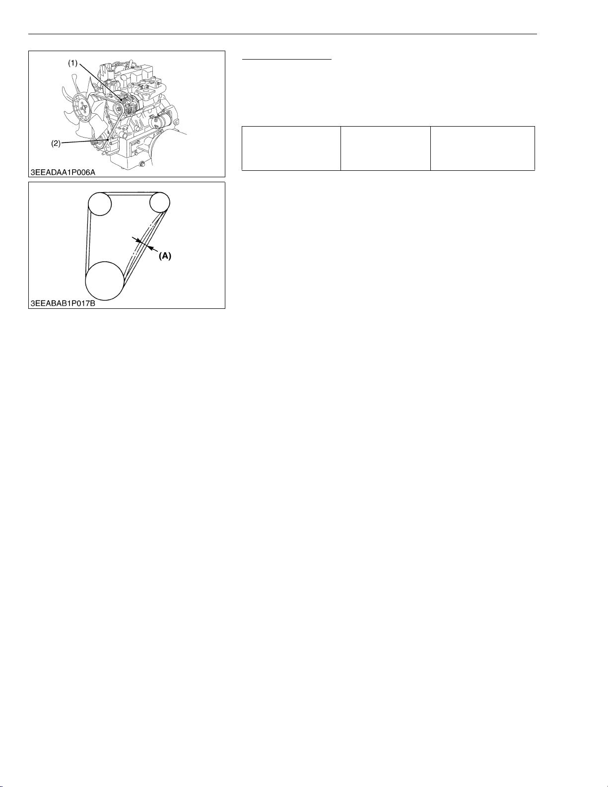
03-M-DI Series, WSM
KiSC issued 10, 2009 A
Replacing Fan Belt
1. Remove the alternator (1).
2. Remove the fan belt (2).
3. Replace new fan belt.
4. Install the alternator (1).
5. Check the fan belt tension.
Deflection (A) Factory spec.
(1) Alternator (A) Deflection
(2) Fan Belt
DIESEL ENGINE
7.0 to 9.0 mm
/ 98 N or 10 kgf
0.28 to 0.35 in.
/ 98 N or 22 lbs.
W1052220
S-28
Page 50

03-M-DI Series, WSM
KiSC issued 10, 2009 A
(7) Check Points of Every 1 or 2 Months
Recharging
• When the battery is being activated, hydrogen and oxygen
• When charging battery, remove battery vent plugs.
• When disconnecting the cable from the battery, start with
• Never check battery charge by placing a metal object across
1) Slow Charging
1. Add distilled water if the electrolyte level is low. When charging,
2. Connect the battery to the charging unit, following the
3. As the electrolyte generates gas while charging, remove all port
4. The electrolyte temperature must not exceed 40 °C (105 °F)
5. When charging several batteries in series, charging at the rate of
2) Quick Charging
1. Determine the proper charging current and charging time with the
2. Determine the proper charging current as 1/1 of the battery
Q Precaution for Operating a Quick Charger
• Operating with a quick charger differs according to the type.
DIESEL ENGINE
CAUTION
gases in the battery are extremely explosive. Keep open
sparks and flames away from the battery at all times,
especially when charging the battery.
the negative terminal first. When connecting the cable to the
battery, start with the positive terminal first.
the posts.
Use a voltmeter or hydrometer.
the amount of electrolyte should be slightly lower than the
specified level to prevent overflow.
manufacture’s instructions.
caps.
during charging.
If it exceed 40 °C (105 °F), decrease the charging amperage or
stop charging for a while.
the smallest battery in the line.
tester attached to the quick charger.
capacity. If the battery capacity exceeds 50 Ah, consider 50 A as
the maximum.
Consult the instruction manual and use accordingly.
W1052658
S-29
Page 51
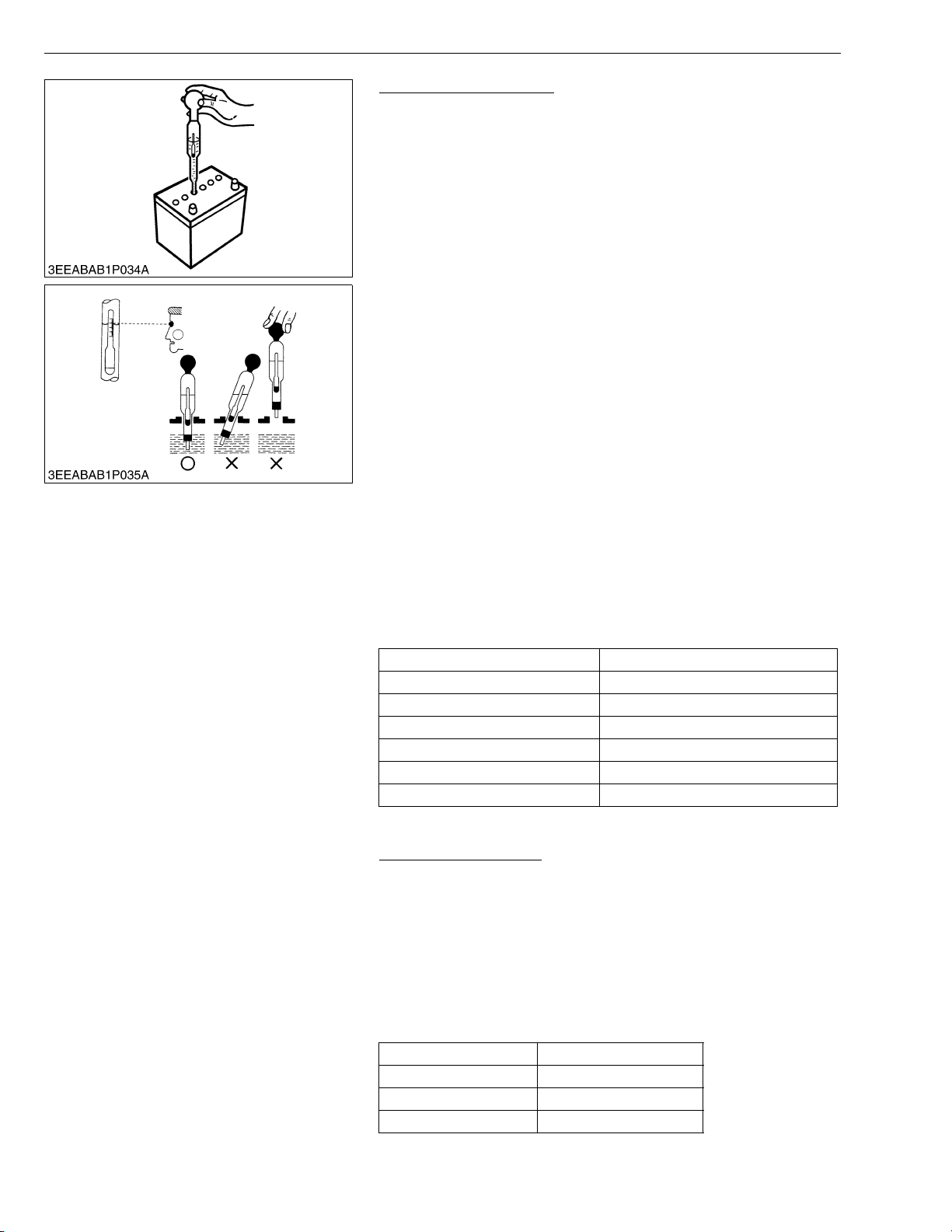
03-M-DI Series, WSM
KiSC issued 10, 2009 A
DIESEL ENGINE
Battery Specific Gravity
1. Check the specific gravity of the electrolyte in each cell with a
hydrometer.
2. When the electrolyte temperature differs from that at which the
hydrometer was calibrated, correct the specific gravity reading
following the formula mentioned in (Reference).
3. If the specific gravity is less than 1.215 (after it is corrected for
temperature), charge or replace the battery.
4. If the specific gravity differs between any two cells by more than
0.05, replace the battery.
NOTEQ
• Hold the hydrometer tube vertical without removing it from
the electrolyte.
• Do not suck too much electrolyte into the tube.
• Allow the float to move freely and hold the hydrometer at eye
level.
• The hydrometer reading must be taken at the highest
electrolyte level.
(Reference)
• Specific gravity slightly varies with temperature. To be exact, the
specific gravity decreases by 0.0007 with an increase of 1 °C
(0.0004 with an increase of 1 °F) in temperature, and increases
by 0.0007 with a decreases of 1 °C (0.0004 with a decrease of 1
°F).
Therefore, using 20 °C (68 °F) as a reference, the specific gravity
reading must be corrected by the following formula :
- Specific gravity at 20 °C = Measured value + 0.0007 ×
(electrolyte temperature : 20 °C)
- Specific gravity at 68 °F = Measured value + 0.0004 ×
(electrolyte temperature : 68 °F)
Specific Gravity State of Charge
1.260 Sp. Gr. 100 % Charged
1.230 Sp. Gr. 75 % Charged
1.200 Sp. Gr. 50 % Charged
1.170 Sp. Gr. 25 % Charged
1.140 Sp. Gr. Very Little Useful Capacity
1.110 Sp. Gr. Discharged
At an electrolyte temperature of 20 °C (68 °F)
W1012763
Directions for Storage
1. When shutting down the tractor for long periods of time, remove
the battery from the tractor, adjust the electrolyte to the proper
level, and after fully charging, store the battery in a well ventilated
placed where it is not exposed to direct sunlight.
2. Since the battery self-discharges by approx. 0.5 % per day even
in storage, it must be once every two months in cold season.
3. When storaging the battery mounted on the tractor, disconnect
the ground cable from the battery’s negative terminal post.
Self-discharge Rate
Temperature Self-discharge rate
30 °C (86 °F) Approx. 1.0 % per day
20 °C (68 °F) Approx. 0.5 % per day
10 °C (50 °F) Approx. 0.25 % per day
W1053636
S-30
Page 52
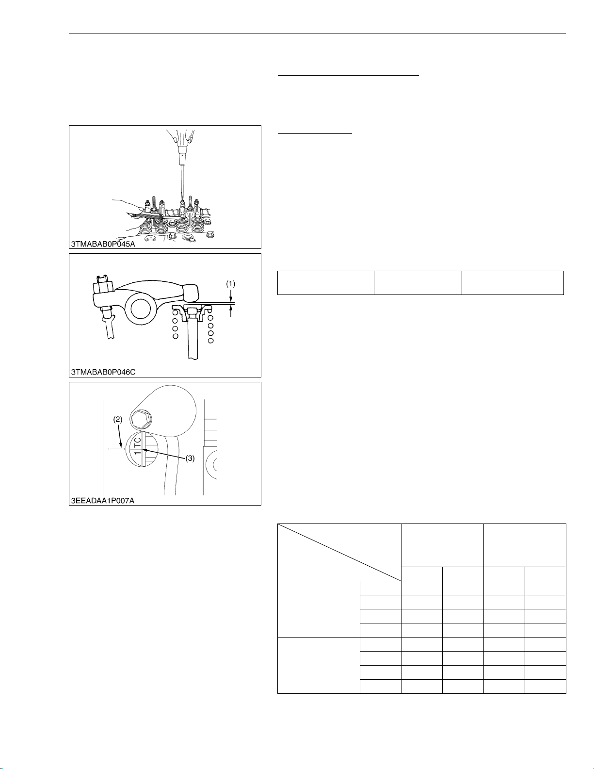
03-M-DI Series, WSM
KiSC issued 10, 2009 A
(8) Check Point of Every Year
(9) Check Point of Every 800 Hours
DIESEL ENGINE
Replacing Air Cleaner Element
See page S-21.
W1054408
Valve Clearance
IMPORTANTQ
• Valve clearance must be checked and adjusted when engine
is cold.
1. Remove the head cover.
2. Align the “1TC” mark line (3) on the flywheel and projection (2)
on the housing so that the No.1 piston comes to the compression
or overlap top dead center.
3. Check the following valve clearance (1) marked with “,” using a
feeler gauge.
4. If the clearance is not within the factory specifications, adjust with
the adjusting screw.
Valve clearance Factory spec.
0.18 to 0.22 mm
0.0071 to 0.0086 in.
NOTEQ
• The “TC” marking line on the flywheel is just for No. 1
cylinder. There is no “TC” marking for the other cylinders.
• No. 1 piston comes to the top dead center position when the
“TC” marking is aligned with the projection (2) in the window
on flywheel-housing. Turn the flywheel 0.26 rad (15°)
clockwise and counterclockwise to see if the piston is at the
compression top dead center or the overlap position. Now
referring to the table below, readjust the valve clearance (1).
(The piston is at the top dead center when both the IN. and
EX. valves do not move; it is at the overlap position when
both the valves move.)
• Finally turn the flywheel 6.28 rad (360°) and align the “TC”
marking and the projection (2) perfectly. Adjust all the other
valve clearance as required.
• After turning the flywheel counterclockwise twice or three
times, recheck the valve clearance (1).
• After adjusting the valve clearance (1), firmly tighten the lock
nut of the adjusting screw.
Valve
arrangement
Adjustable
cylinder
location of piston
No. 1 ,,,,
When No. 1 piston is
compression top
dead center
When No. 1 piston is
overlap position
No. 2 ,,
No. 3 ,,
No. 4 – –
No. 1
No. 2 ,,
No. 3 ,,
No. 4 – – ,,
D1503-M-DI
D1503-M-DI-T
D1703-M-DI
D1803-M-DI
IN. EX. IN. EX.
V2203-M-DI
V2403-M-DI
(1) Valve Clearance
(2) Projection
S-31
(3) TC Mark Line
W10113200
Page 53
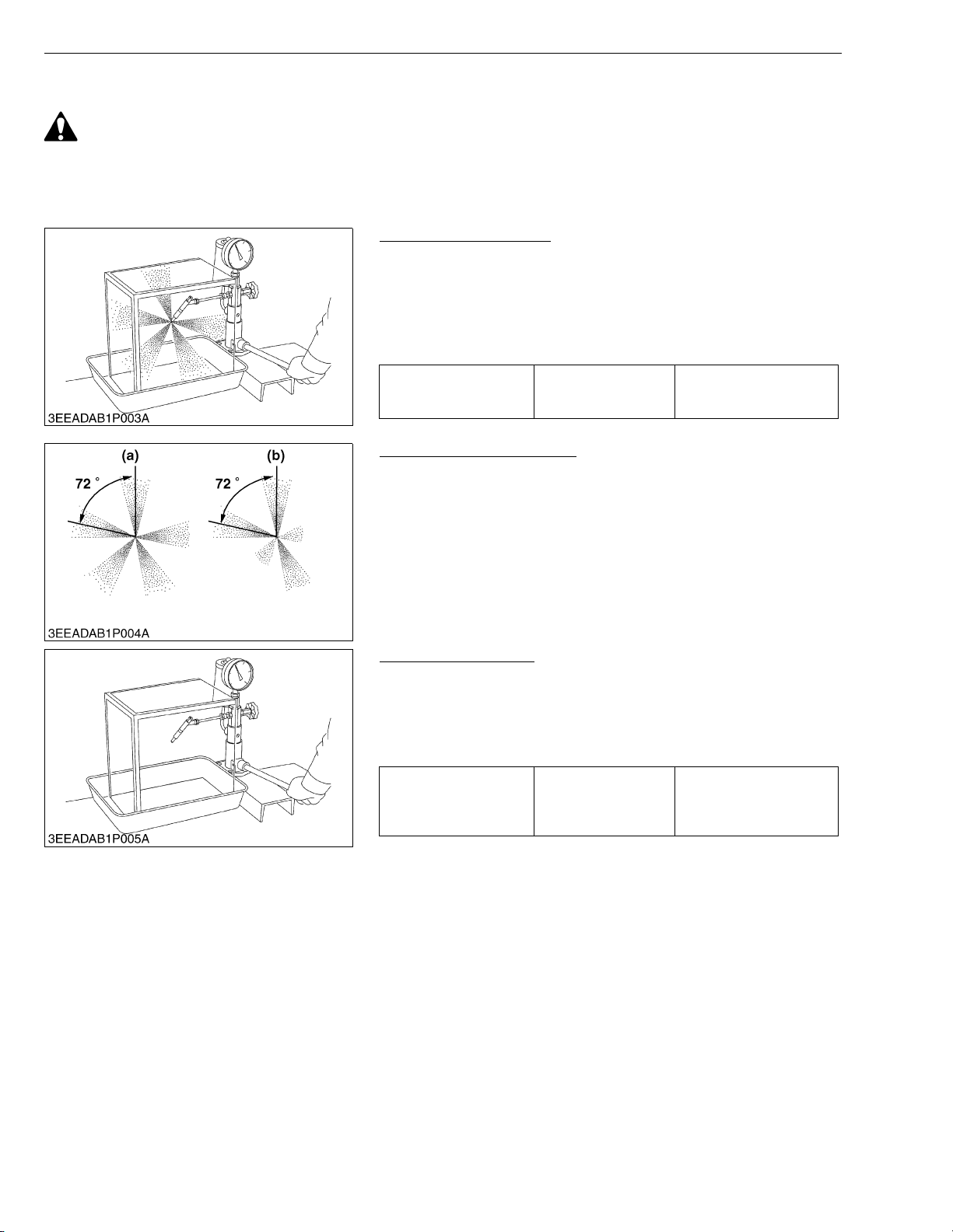
03-M-DI Series, WSM
KiSC issued 10, 2009 A
DIESEL ENGINE
(10) Check Points of Every 1500 Hours
CAUTION
• Check the injection pressure and condition after confirming that there is nobody standing in the direction
the fume goes.
If the fume from the nozzle directly contacts the human body, cells may be destroyed and blood poisoning
may be caused.
Fuel Injection Pressure
1. Set the injection nozzle to a nozzle tester (Code No. 07909-
31361).
2. Slowly move the tester handle to measure the pressure at which
fuel begins jetting out from the nozzle.
3. If the measurement is not within the factory specifications,
replace the injection nozzle assembly.
Fuel injection pressure
1st. stage
Factory spec.
Nozzle Spraying Condition
1. Set the injection nozzle to a nozzle tester (Code No. 07909-
31361), and check the nozzle spraying condition.
2. If the spraying condition is defective, replace the injection nozzle
assembly.
(a) Good (b) Bad
18.6 to 20.1 MPa
190 to 205 kgf/cm
2702 to 2916 psi
2
W10408820
W10411400
Valve Seat Tightness
1. Set the injection nozzle to a nozzle tester (Code No. 07909-
31361).
2. Raise the fuel pressure, and keep at 16.67 MPa (170 kgf/cm
2418 psi) for 10 seconds.
3. If any fuel leak is found, replace the injection nozzle assembly.
No fuel leak at
Valve seat tightness Factory spec.
16.67 MPa
170 kgf/cm
2418 psi
2
W10412730
2
,
S-32
Page 54

03-M-DI Series, WSM
KiSC issued 10, 2009 A
(11) Check Point of Every 3000 Hours
(12) Check Points of Every 2 Years
DIESEL ENGINE
Checking Turbocharger
See page S-101.
W1056274
Replacing Intake Air Line
See page S-23.
W1117974
Replacing Battery
See page S-21, 30.
W1056352
Replacing Radiator Hoses and Clamp Bands
See page S-23.
W1056385
Replacing Fuel Pipes and Clamp Bands
See page S-20.
W1056418
Changing Radiator Coolant (L.L.C.)
See page S-26, 27.
W1056536
S-33
Page 55
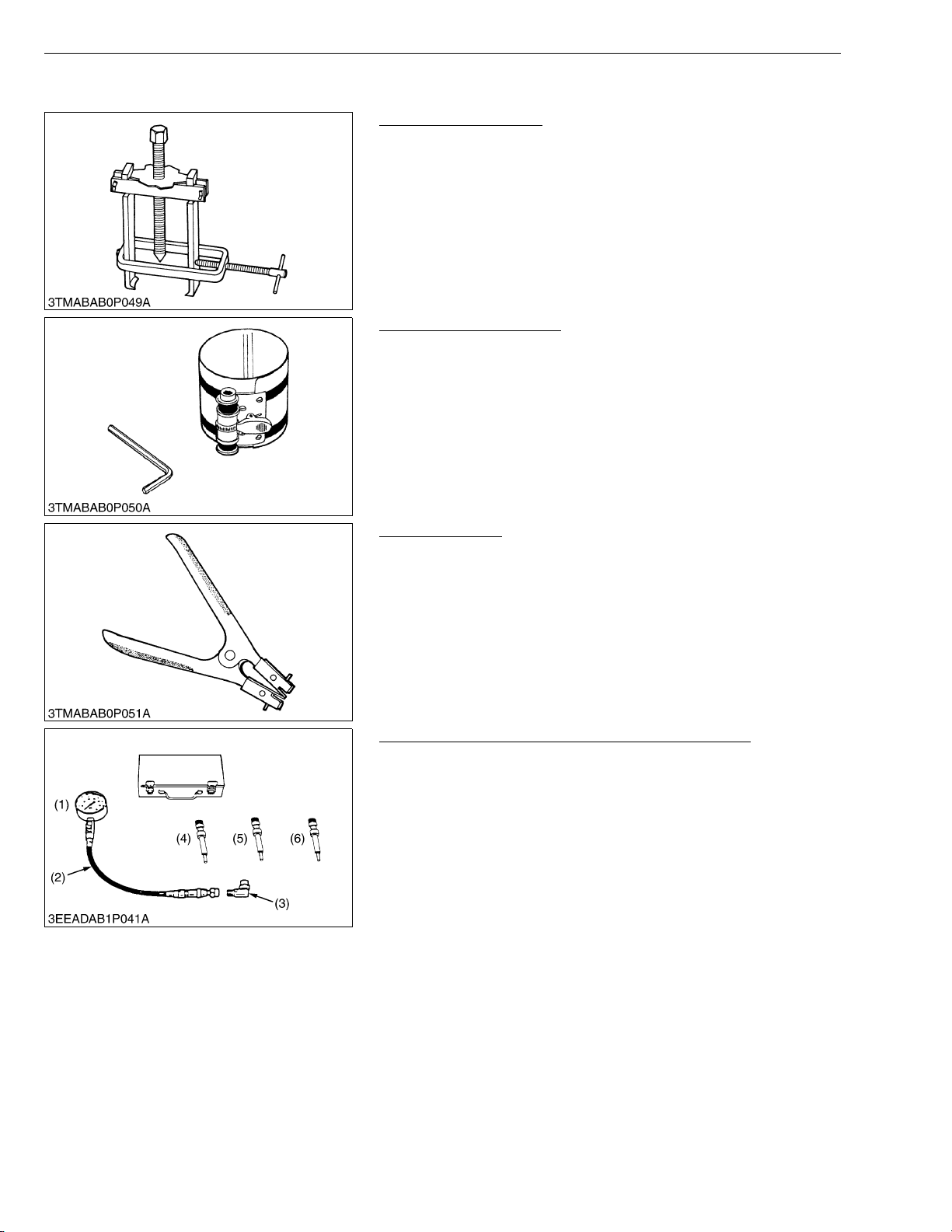
03-M-DI Series, WSM
KiSC issued 10, 2009 A
[8] SPECIAL TOOLS
DIESEL ENGINE
Special Use Puller Set
Code No: 07916-09032
Application: Use exclusively for pulling out bearing, gears and other
parts with ease.
W1024050
Piston Ring Compressor
Code No: 07909-32111
Application: Use exclusively for pushing in the piston with piston
rings into the cylinder.
W1024100
Piston Ring Tool
Code No: 07909-32121
Application: Use exclusively for removing or installing the piston ring
with ease.
W1024150
Diesel Engine Compression Tester (for Glow Plug)
Code No: 07909-39081 (Assembly)
07909-31291 (K)
07909-31301 (L)
07979-31311 (M)
Application: Use to measure diesel engine compression and
diagnosis of need for major overhaul.
Adaptor: The adaptor K is required for V2203-EDI.
(1) Gauge
(2) Hose Assembly
(3) L Joint
(4) Adaptor K
(5) Adaptor L
(6) Adaptor M
W1206183
S-34
Page 56
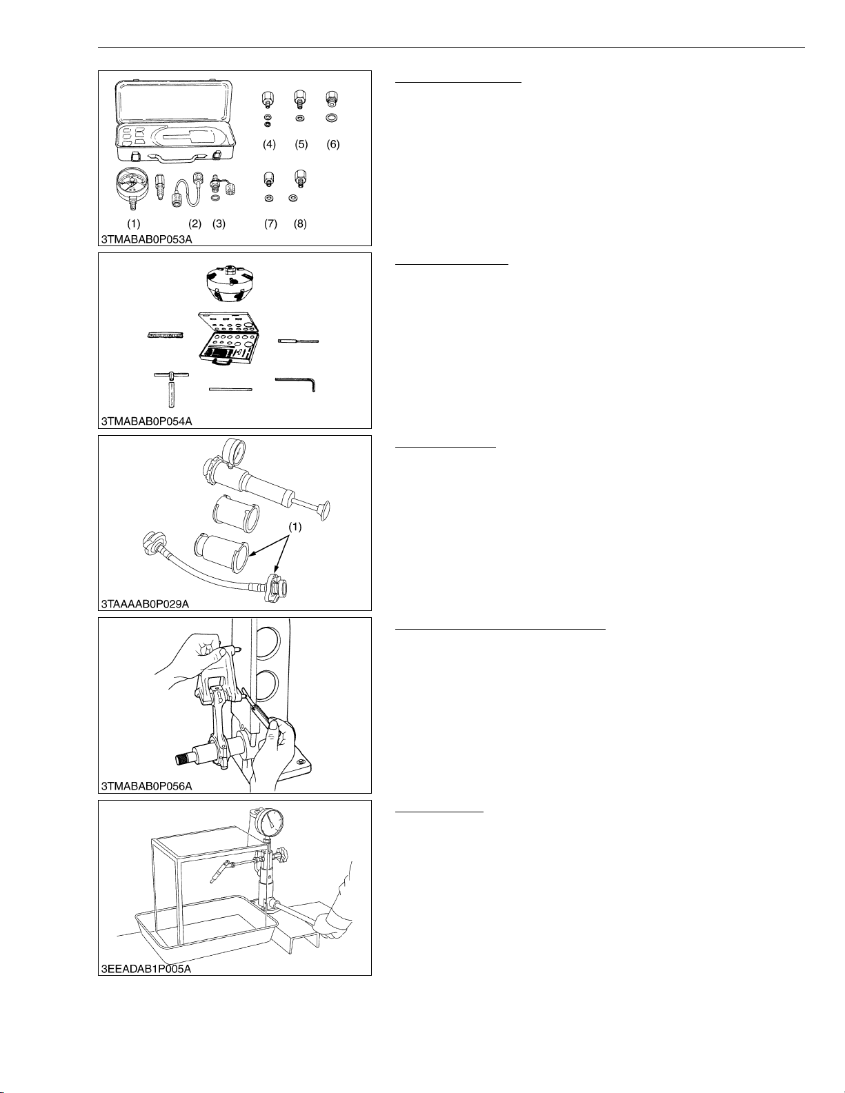
03-M-DI Series, WSM
KiSC issued 10, 2009 A
DIESEL ENGINE
Oil Pressure Tester
Code No: 07916-32032
Application: Use to measure lubricating oil pressure.
(1) Gauge
(2) Cable
(3) Threaded Joint
(4) Adaptor 1
(5) Adaptor 2
(6) Adaptor 3
(7) Adaptor 4
(8) Adaptor 5
Valve Seat Cutter
Code No: 07909-33102
Application: Use to reseat valves.
Angle: 0.785 rad (45°)
0.262 rad (15°)
Diameter: 28.6 mm (1.126 in.) 38.0 mm (1.496 in.)
31.6 mm (1.244 in.) 41.3 mm (1.626 in.)
35.0 mm (1.378 in.) 50.8 mm (2.000 in.)
W1024318
W1024458
Radiator Tester
Code No: 07909-31551
Application: Use to check of radiator cap pressure, and leaks from
cooling system.
Remarks: Adapter (1) BANZAI Code No. RCT-2A-30S
W1024532
Connecting Rod Alignment Tool
Code No: 07909-31661
Application: Use to check the connecting rod alignment.
Applicable: Connecting rod big end I.D.
range 30 to 75 mm (1.18 to 2.95 in.) dia.
Connecting rod length
65 to 300 mm (2.56 to 11.81 in.)
W1024583
Nozzle Tester
Code No: 07909-31361
Application: Use to check the fuel injection pressure and spray
pattern of nozzle.
Measuring: 0 to 50 MPa
range (0 to 500 kgf/cm
2
, 0 to 7000 psi)
W1024653
S-35
Page 57
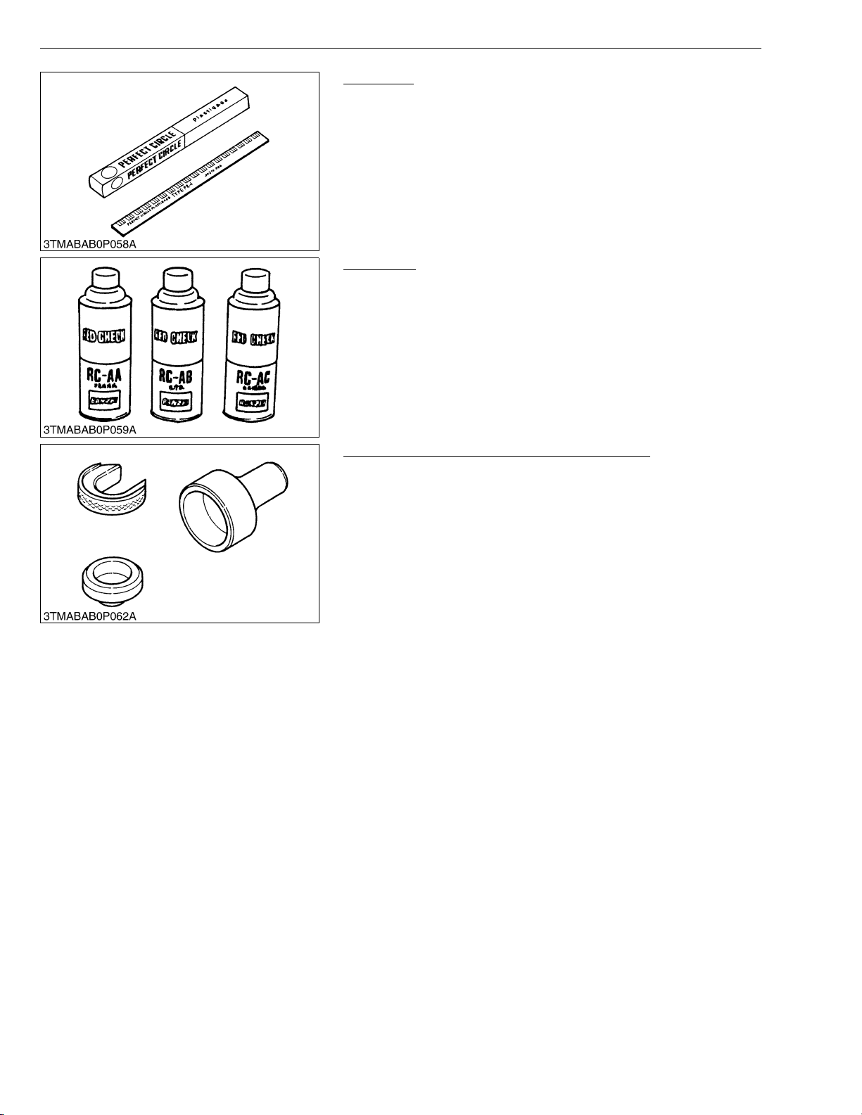
03-M-DI Series, WSM
KiSC issued 10, 2009 A
DIESEL ENGINE
Plastigage
Code No: 07909-30241
Application: Use to check the oil clearance between crankshaft and
bearing, etc.
Measuring: Green .... 0.025 to 0.076 mm (0.001 to 0.003 in.)
range Red........ 0.051 to 0.152 mm (0.002 to 0.006 in.)
Blue ....... 0.102 to 0.229 mm (0.004 to 0.009 in.)
W1024719
Red Check
Code No: 07909-31371
Application: Use to check cracks on cylinder head, cylinder block,
etc.
W1024909
Auxiliary Socket For Fixing Crankshaft Sleeve
Code No: 07916-32091
Application: Use to fix the crankshaft sleeve of the diesel engine.
W1077114
S-36
Page 58
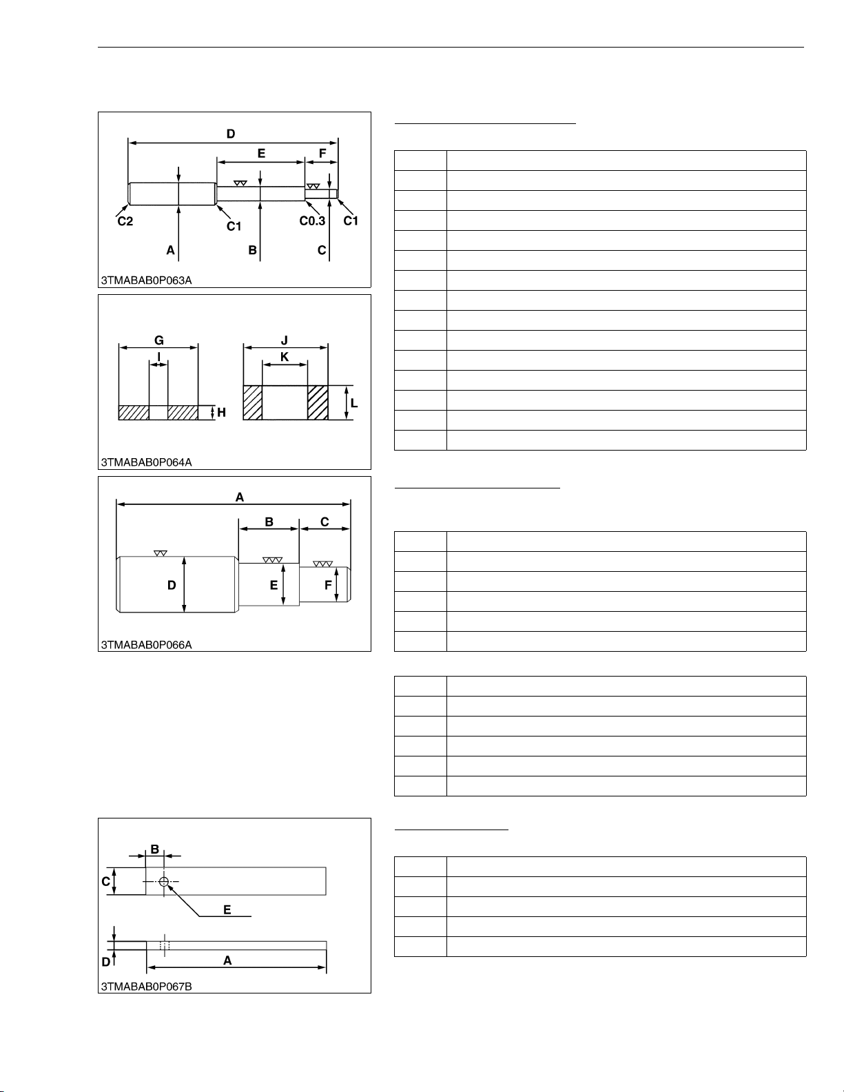
03-M-DI Series, WSM
KiSC issued 10, 2009 A
NOTEQ
• The following special tools are not provided, so make them referring to the figure.
Valve Guide Replacing Tool
Application: Use to press out and press fit the valve guide.
A 20 mm dia. (0.79 in. dia.)
B 11.7 to 11.9 mm dia. (0.460 to 0.468 in. dia.)
C 6.5 to 6.6 mm dia. (0.256 to 0.259 in. dia.)
D 225 mm (8.86 in.)
E 70 mm (2.76 in.)
F 45 mm (1.77 in.)
G 25 mm (0.98 in.)
H 5 mm (0.197 in.)
I 6.7 to 7.0 mm dia. (0.263 to 0.275 in. dia.)
J 20 mm dia. (0.787 in. dia.)
K 12.5 to 12.8 mm dia. (0.492 to 0.504 in. dia.)
L 8.9 to 9.1 mm (0.350 to 358 in.)
C1 Chamfer 1.0 mm (0.039 in.)
C2 Chamfer 2.0 mm (0.079 in.)
C0.3 Chamfer 0.3 mm (0.012 in.)
Bushing Replacing Tools
Application: Use to press out and to press fit the bushing.
(1) For small end bushing
A 162 mm (6.38 in.)
B 35 mm (1.38 in.)
C 27 mm (1.06 in.)
D 35 mm dia. (1.38 in. dia.)
E 27.90 to 27.95 mm dia. (1.098 to 1.100 in. dia.)
F 25.00 to 25.01 mm dia. (0.984 to 0.985 in. dia.)
(2) For idle gear bushing
A 175 mm (6.89 in.)
B 40 mm (1.57 in.)
C 38 mm (1.49 in.)
D 45 mm dia. (1.77 in. dia.)
E 41.90 to 41.95 mm dia. (1.650 to 1.652 in. dia.)
F 37.95 to 37.97 mm dia. (1.494 to 1.495 in. dia.)
Flywheel Stopper
Application: Use to loosen and tighten the flywheel screw.
A 200 mm (7.87 in.)
B 20 mm (0.79 in.)
C 30 mm (1.18 in.)
D 8 mm (0.31 in.)
E 10 mm dia. (0.39 in. dia.)
DIESEL ENGINE
W1025017
W1025500
W1025948
S-37
Page 59
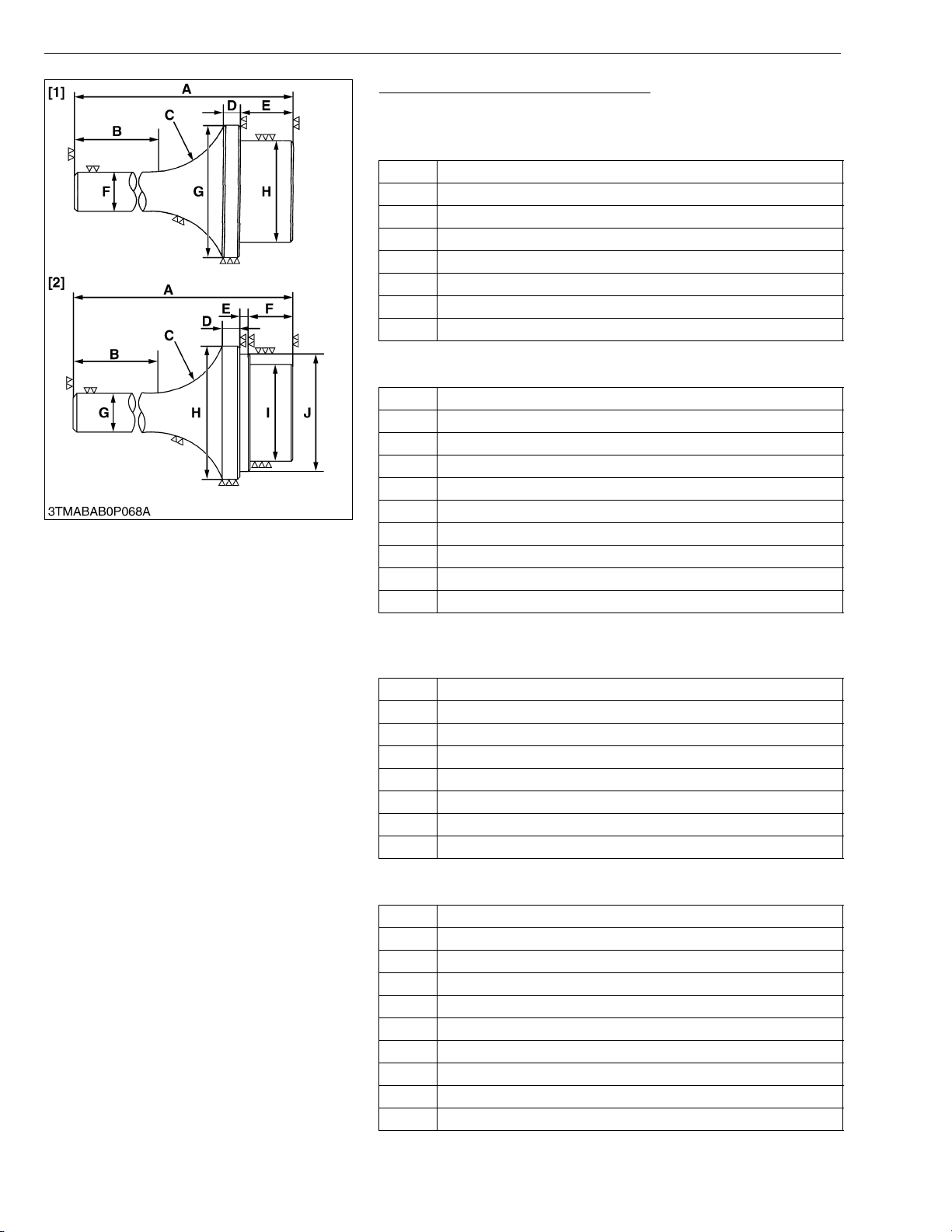
03-M-DI Series, WSM
KiSC issued 10, 2009 A
DIESEL ENGINE
Crankshaft Bearing 1 Replacing Tool
Application: Use to press out and press fit the crankshaft bearing 1.
1. Extracting tool
(D1503, D1703, V2203 : Serial No. : below 3R9999)
A 135 mm (5.31 in.)
B 72 mm (2.83 in.)
C R40 mm (R1.57 in.)
D 10 mm (0.39 in.)
E 20 mm (0.79 in.)
F 20 mm dia. (0.79 in. dia.)
G 56.8 to 56.9 mm dia. (2.236 to 2.240 in. dia.)
H 51.8 to 51.9 mm dia. (2.039 to 2.043 in. dia.)
2. Inserting tool
(D1503, D1703, V2203 : Serial No. : below 3R9999)
A 130 mm (5.12 in.)
B 72 mm (2.83 in.)
C R40 mm (R1.57 in.)
D 9 mm (0.35 in.)
E 4 mm (0.16 in.)
F 20 mm (0.79 in.)
G 20 mm dia. (0.79 in. dia.)
H 68 mm dia. (2.68 in. dia.)
I 51.8 to 51.9 mm dia. (2.039 to 2.043 in. dia.)
J 56.8 to 56.9 mm dia. (2.236 to 2.240 in. dia.)
1. Extracting tool (D1803, V2403 : Serial No. : below 3R9999)
(Serial No. : above 3S0001)
A 135 mm (5.31 in.)
B 72 mm (2.83 in.)
C R40 mm (R1.57 in.)
D 10 mm (0.39 in.)
E 20 mm (0.79 in.)
F 20 mm dia. (0.79 in. dia.)
G 64.8 to 64.9 mm dia. (2.551 to 2.555 in. dia.)
H 59.8 to 59.9 mm dia. (2.354 to 2.358 in. dia.)
2. Inserting tool (D1803, V2403 : Serial No. : below 3R9999)
(Serial No. : above 3S0001)
A 130 mm (5.12 in.)
B 72 mm (2.83 in.)
C R40 mm (R1.57 in.)
D 9 mm (0.35 in.)
E 4 mm (0.16 in.)
F 20 mm (0.79 in.)
G 20 mm dia. (0.79 in. dia.)
H 68 mm dia. (2.68 in. dia.)
I 59.8 to 59.9 mm dia. (2.354 to 2.358 in. dia.)
J 64.8 to 64.9 mm dia. (2.551 to 2.555 in. dia.)
W1026139
S-38
Page 60
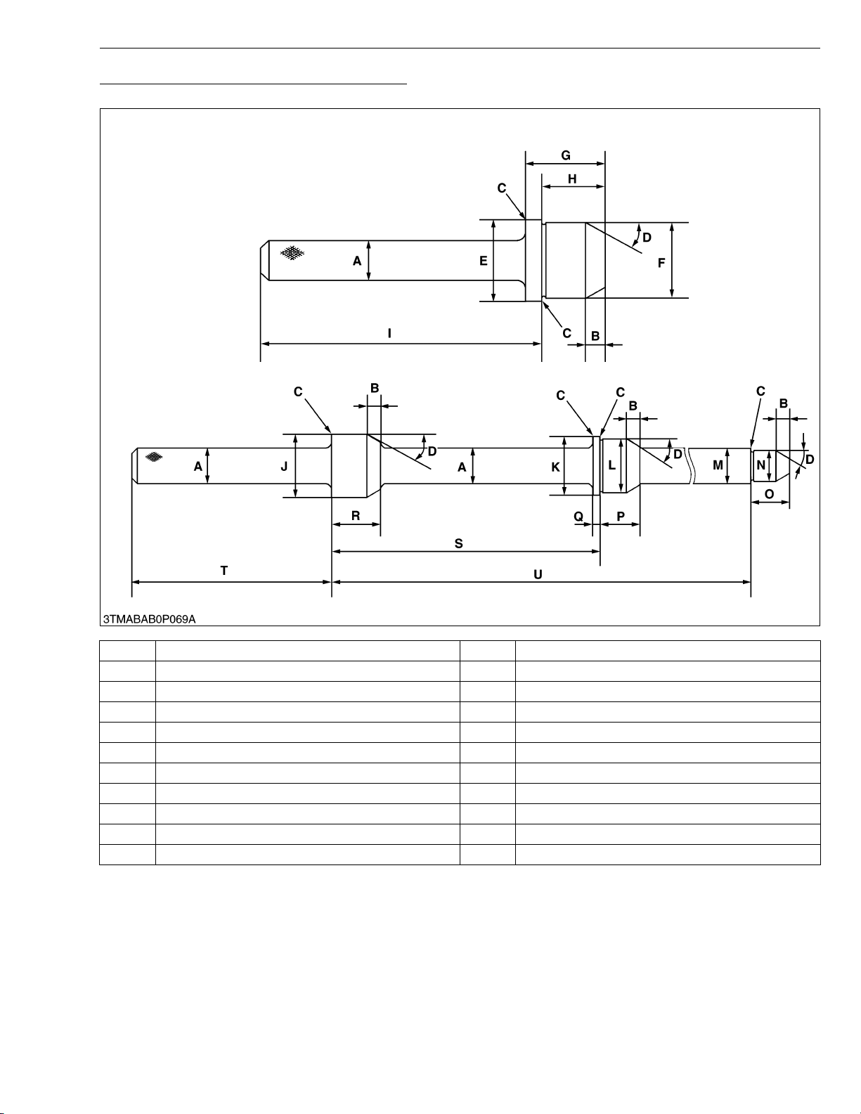
03-M-DI Series, WSM
KiSC issued 10, 2009 A
Balancer Metal Replacing Tool (for Removing)
Application: Use to remove the metal bearing.
DIESEL ENGINE
A 25 mm (0.98 in. dia.) L 41.934 to 41.950 mm dia. (1.6509 to 1.6516 in. dia.)
B 10 mm (0.39 in.) M 24.959 to 24.980 mm dia. (0.9826 to 0.9835 in. dia.)
C Chamfer 0.3 mm (0.01 in.) N 21.947 to 21.960 mm dia. (0.8641 to 0.8646 in. dia.)
D 0.52 rad (30 °) O 28 mm (1.10 in.)
E 46.950 to 46.975 mm dia. (1.8484 to 1.8494 in. dia.) P 29 mm (1.14 in.)
F 43.934 to 43.950 mm dia. (1.7297 to 1.7303 in. dia.) Q 5 mm (0.20 in.)
G 41 mm (1.61 in.) R 36 mm (1.42 in.)
H 32.5 mm (1.28 in.) S 195.25 to 195.75 mm (7.687 to 7.707 in.)
I 148.5 mm (5.85 in.) T 145 mm (5.71 in.)
J 46.50 to 46.75 mm dia. (1.831 to 1.841 in. dia.) U 384.75 to 385.25 mm (15.148 to 15.167 in.)
K 44.950 to 44.975 mm dia. (1.7697 to 1.7707 in. dia.)
S-39
Page 61
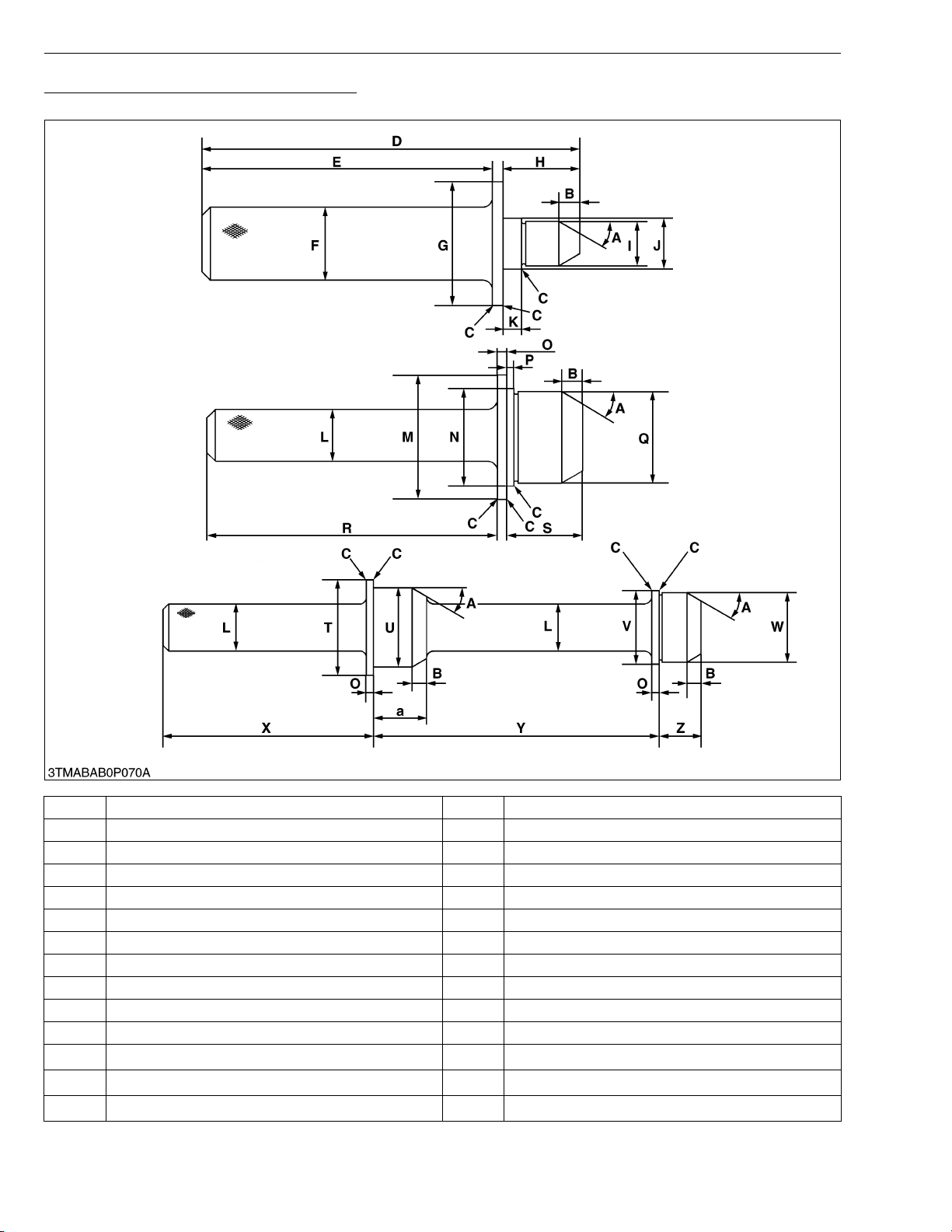
03-M-DI Series, WSM
KiSC issued 10, 2009 A
Balancer Metal Replacing Tool (for Fitting)
Application: Use to press fit the metal bearing.
DIESEL ENGINE
A 0.52 rad (30 °) O 5 mm (0.20 in.)
B 10 mm (0.39 in.) P 3.3 to 3.7 mm (0.130 to 0.146 in.)
C Chamfer 0.3 mm (0.01 in.) Q 43.934 to 43.950 mm dia. (1.7297 to 1.7303 in. dia.)
D 182 mm (7.16 in.) R 140 mm (5.51 in.)
E 140 mm (5.51in.) S 36 mm (1.42 in.)
F 35 mm dia. (1.38 in dia.) T 60 mm dia. (2.36 in. dia.)
G 60 mm dia. (2.36 in dia.) U 46.950 to 46.975 mm dia. (1.8484 to 1.8494 in. dia.)
H 37 mm (1.46 in.) V 44.950 to 44.975 mm dia. (1.7697 to 1.7707 in. dia.)
I 21.947 to 21.960 mm dia. (0.8641 to 0.8646 in. dia.) W 41.934 to 41.950 mm dia. (1.6509 to 1.6516 in. dia.)
J 24.959 to 24.980 mm dia. (0.9826 to 0.9835 in. dia.) X 145 mm (5.71 in.)
K 8.8 to 9.2 mm (0.346 to 0.362 in.) Y 195.25 to 195.75 mm (7.687 to 7.707 in.)
L
25 mm dia. (0.98 in. dia.)
M
60 mm dia. (2.36 in. dia.)
N
46.950 to 46.975 mm dia. (1.8484 to 1.8494 in. dia.)
S-40
Z
a
29 mm (1.14 in.)
36 mm (1.42 in.)
Page 62
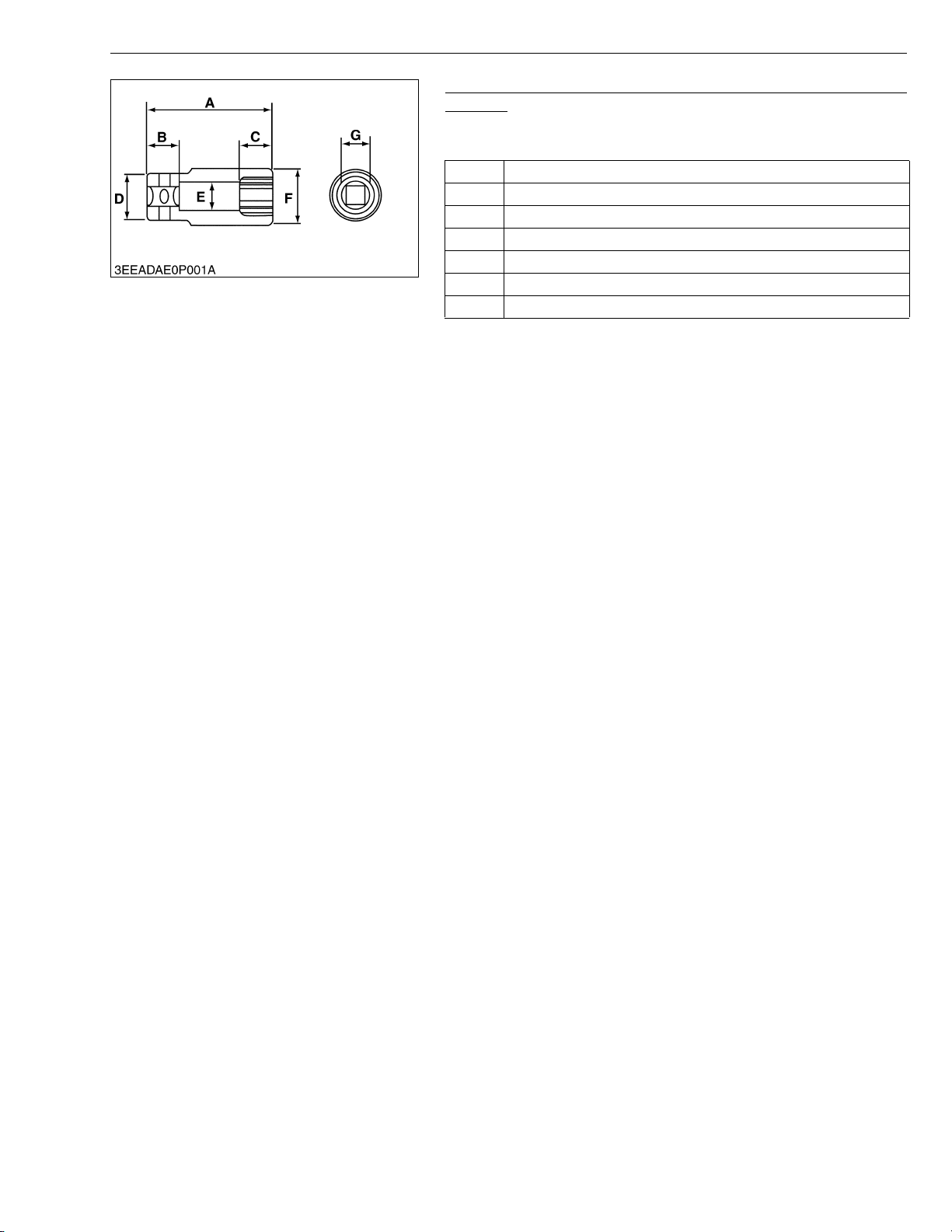
03-M-DI Series, WSM
KiSC issued 10, 2009 A
DIESEL ENGINE
Socket Wrench for Crank Pulley Nut (46 mm Deep Socket
Wrench)
Application: Use to loosen and tighten the fan drive pulley mounting
nut.
A 100 mm (3.94 in.)
B 25.0 mm (0.98 in.)
C 27.0 mm (1.06 in.)
D 45.0 mm dia. (1.77 in. dia.)
E 35.0 mm dia. (1.38 in. dia.)
F 62.5 mm dia. (2.46 in. dia.)
G 46.0 mm (1.81 in.)
W1044361
S-41
Page 63
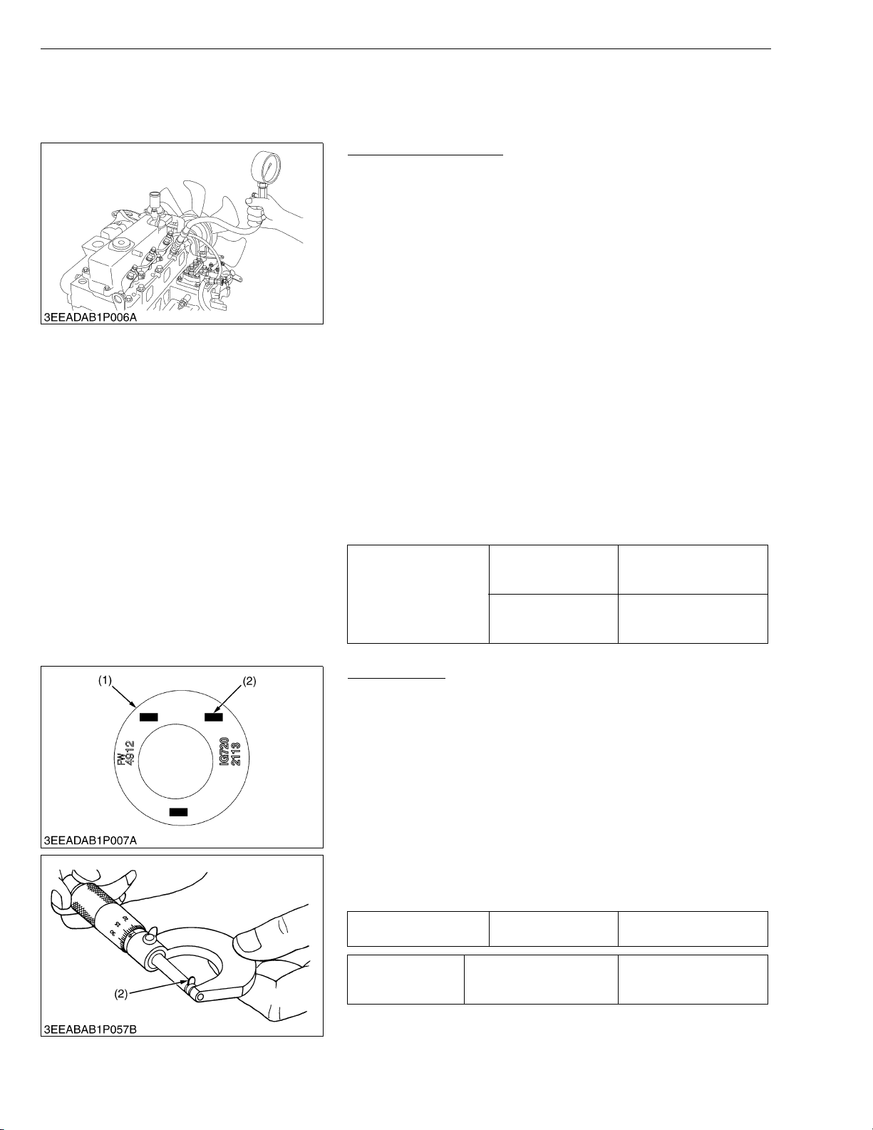
03-M-DI Series, WSM
KiSC issued 10, 2009 A
2. ENGINE BODY
[1] CHECKING AND ADJUSTING
Compression Pressure
1. Run the engine until it is warmed up.
2. Stop the engine and disconnect the 2P connector from the stop
3. Remove the air cleaner, the muffler and all glow plugs.
4. Set a compression tester with the adaptor K to the glow plug
5. While cranking the engine with the starter, measure the
6. Repeat steps 4 through 6 for each cylinder.
7. If the measurement is below the allowable limit, apply a small
8. If the compression pressure is still less than the allowable limit,
9. If the compression pressure increases after applying oil, check
• Check the compression pressure with the specified valve
• Always use a fully charged battery for performing this test.
• Variances in cylinder compression values should be under
Compression pressure
Top Clearance
1. Remove the cylinder head.
2. Move the piston up and stick a strip of fuse (2) on the piston head
3. Lower the piston and install the cylinder head. (Use a new
4. Turn the flywheel until the piston (1) passes through the top dead
5. Remove the cylinder head and measure the thickness of the
6. If the measurement is not within the factory specifications, check
Top clearance Factory spec.
DIESEL ENGINE
solenoid in order not to inject fuel.
hole.
compression pressure.
amount of oil to the cylinder wall through the glow plug hole and
measure the compression pressure again.
check the top clearance, valve and cylinder head.
the cylinder wall and piston rings.
NOTEQ
clearance.
10 %.
Factory spec.
Allowable limit
2.94 to 3.24 MPa
30 to 33 kgf/cm
427 to 469 psi
2.35 MPa
24 kgf/cm
341 psi
2
2
W1018639
at three position with grease.
cylinder head gasket and tighten with a specified tightening
torque.)
center.
fuses.
the oil clearances between the crankpin and bearing and
between the piston pin and bushing.
0.60 to 0.70 mm
0.0236 to 0.0276 in.
Tightening torque Cylinder head screws
(1) Piston (2) Fuse
S-42
93.1 to 98.0 N·m
9.5 to 10.0 kgf·m
68.7 to 72.3 ft-lbs
W1020190
Page 64
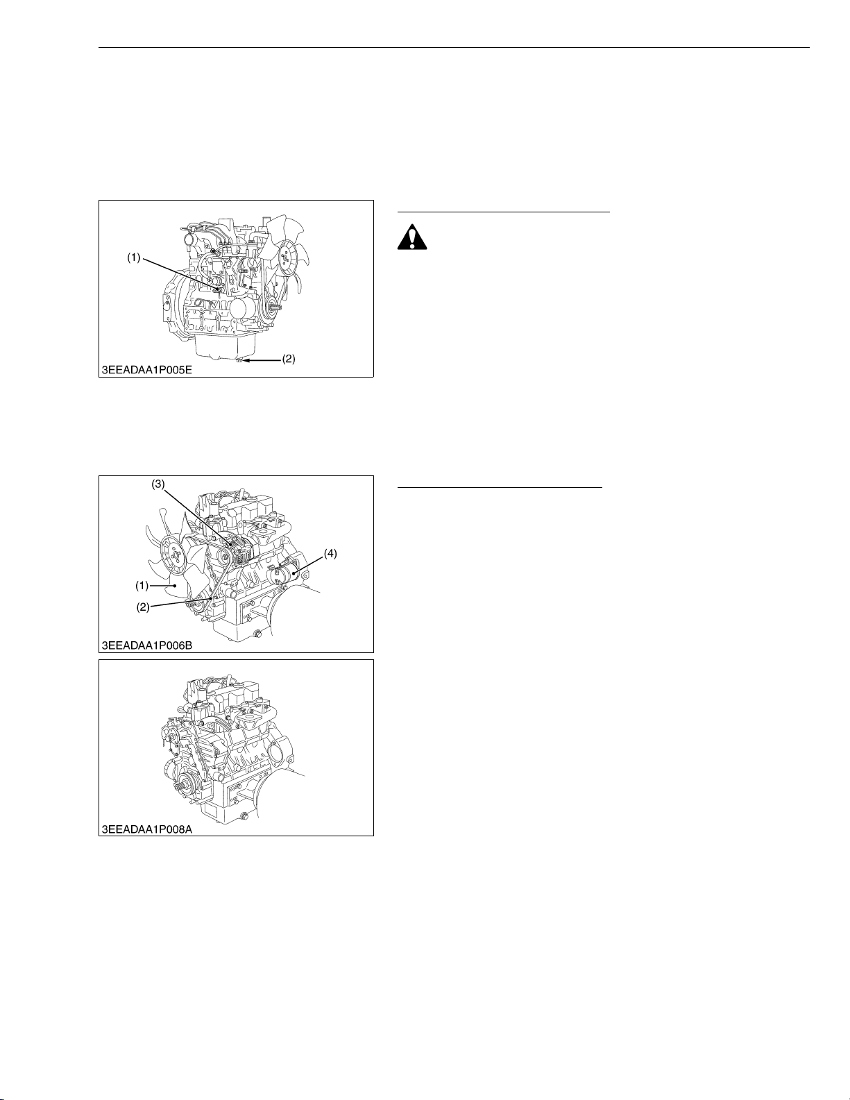
03-M-DI Series, WSM
KiSC issued 10, 2009 A
DIESEL ENGINE
[2] DISASSEMBLING AND ASSEMBLING
(1) Draining Coolant and Oil
NOTEQ
• Some types of gearcases are provided with an oil filter port. When the cylinder head has been
reassembled or when the valve clearance has been readjusted, apply an enough amount of oil to the intake
and exhaust valves, push rod and rocker arm just before fitting the head cover in position.
Draining Coolant and Engine Oil
CAUTION
• Never remove radiator cap until coolant temperature is
below its boiling point. Then loosen cap slightly to the stop
to relieve any excess pressure before removing cap
completely.
1. Prepare a bucket. Open the coolant drain cock (1) to drain
coolant.
2. Prepare an oil pan. Remove the oil drain plug (2) to drain engine
oil in the pan.
See page S-24, 26.
(1) Coolant Drain Cock (2) Oil Drain Plug
W1060189
(2) External Components
Air Cleaner, Muffler and Others
1. Remove the air cleaner and muffler.
2. Remove the fan (1), fan belt (2), alternator (3) and starter (4).
(When reassembling)
• Check to see that there are no cracks on the belt surface.
IMPORTANTQ
• After reassembling the fan belt, be sure to adjust the fan belt
tension. See page S-28.
• Do not confuse the direction of the fan.
(1) Fan
(2) Fan Belt
(3) Alternator
(4) Starter
W1060302
S-43
Page 65
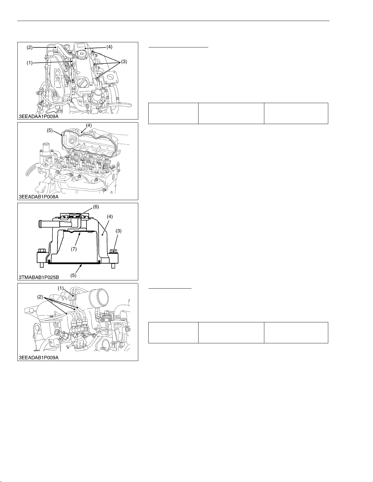
03-M-DI Series, WSM
KiSC issued 10, 2009 A
(3) Cylinder Head and Valves
DIESEL ENGINE
Cylinder Head Cover
1. Remove the lead (1).
2. Remove the breather hose (2).
3. Remove the head cover screws (3).
4. Remove the cylinder head cover (4).
(When reassembling)
• Check to see if the cylinder head cover gasket (5) is not
defective.
6.9 to 11.3 N·m
Tightening torque Cylinder head cover screw
0.7 to 1.15 kgf·m
5.1 to 8.32 ft-lbs
(1) Lead
(2) Breather Hose
(3) Head Cover Screw
(4) Cylinder Head Cover
(5) Cylinder Head Cover Gasket
(6) Breather Valve
(7) Plate
Injection Pipes
1. Loosen the screws on the pipe clamps (1).
2. Detach the injection pipes (2).
(When reassembling)
• Blow out dust inside the pipes.
Tightening torque Injection pipe retaining nut
W1060460
14.7 to 24.5 N·m
1.5 to 2.5 kgf·m
10.8 to 18.1 ft-lbs
(1) Pipe Clamp (2) Injection Pipe
W1060970
S-44
Page 66
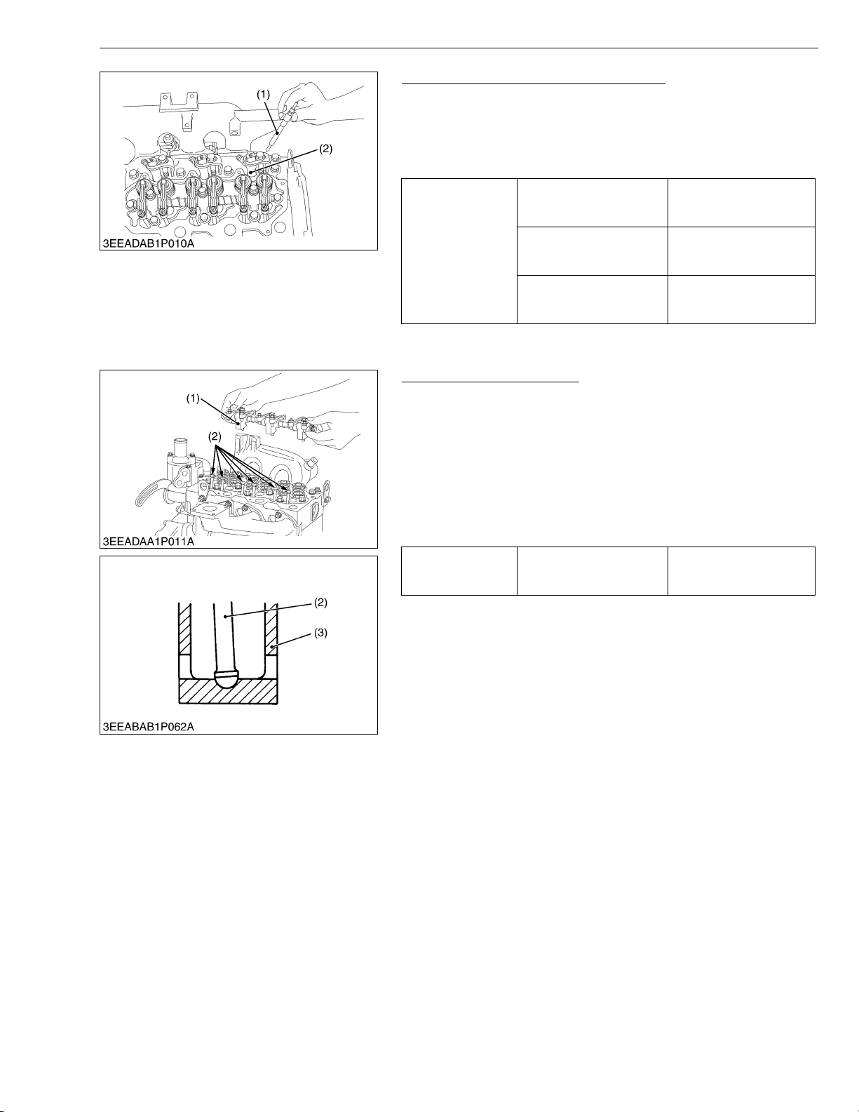
03-M-DI Series, WSM
KiSC issued 10, 2009 A
DIESEL ENGINE
Nozzle Holder Assembly and Glow Plug
1. Remove the overflow pipe assembly.
2. Remove the glow plugs (1).
3. Remove the nozzle holder assemblies (2).
(When reassembling)
• Replace the copper gasket with new one.
25.5 to 29.4 N·m
Nozzle holder clamp screw
Tightening torque
(1) Glow Plug (2) Nozzle Holder Assembly
Overflow pipe assembly
retaining screw
Glow plug
2.6 to 3.0 kgf·m
18.8 to 21.7 ft-lbs
9.8 to 11.3 N·m
1.00 to 1.15 kgf·m
7.2 to 8.3 ft-lbs
19.6 to 24.5 N·m
2.0 to 2.5 kgf·m
14.5 to 18.1 ft-lbs
W1020917
Rocker Arm and Push Rod
1. Remove the rocker arm bracket mounting bolts.
2. Detach the rocker arm assembly (1).
3. Remove the push rods (2).
(When reassembling)
• When putting the push rods (2) onto the tappets (3), check to see
if their ends are properly engaged with the dimples.
IMPORTANTQ
• After installing the rocker arm, be sure to adjust the valve
clearance. See page S-31.
23.5 to 27.5 N·m
2.4 to 2.8 kgf·m
17.4 to 20.3 ft-lbs
Tightening torque
Rocker arm bracket
mounting bolt
(1) Rocker Arm Assembly
(2) Push Rod
(3) Tappet
W1021437
S-45
Page 67
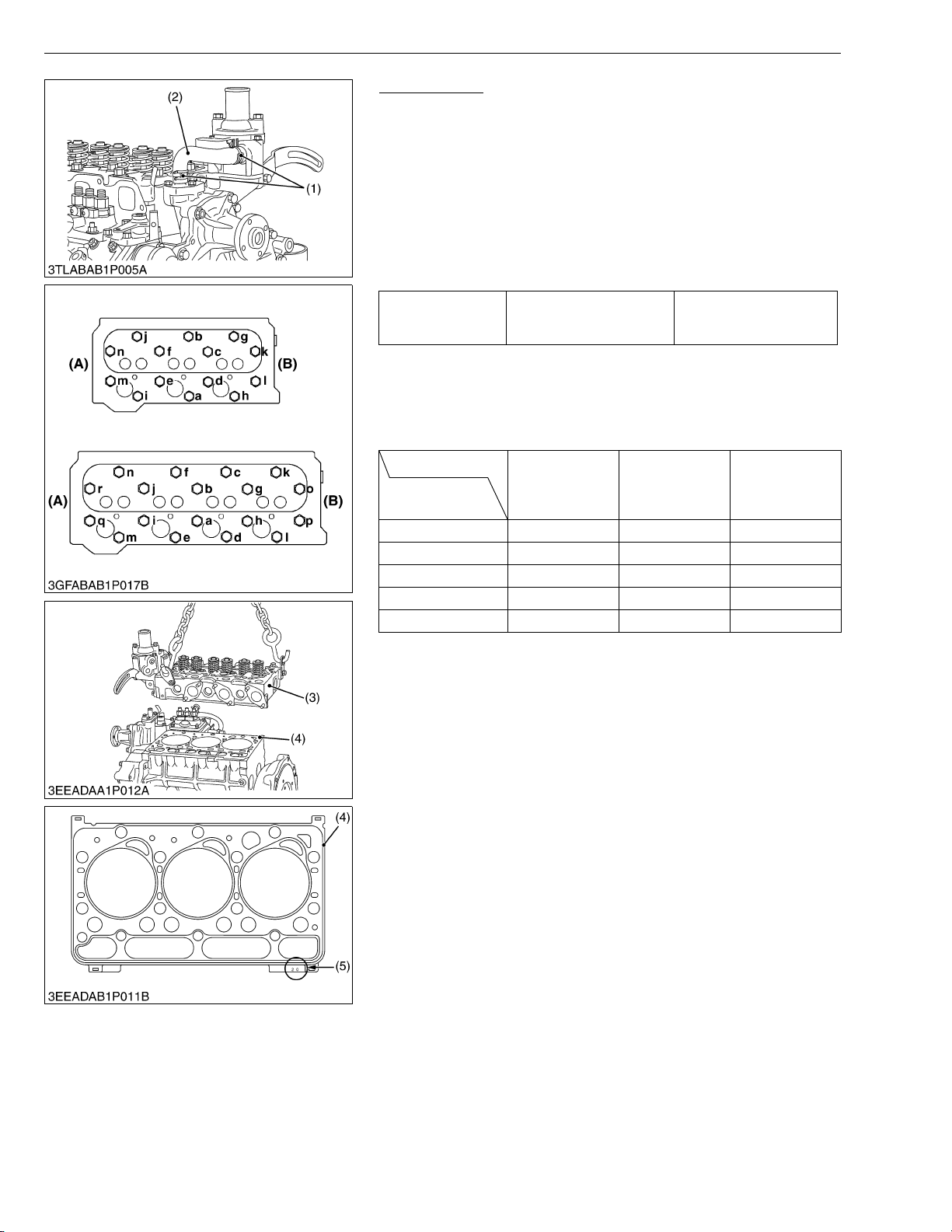
03-M-DI Series, WSM
KiSC issued 10, 2009 A
DIESEL ENGINE
Cylinder Head
1. Loosen the pipe clamp (1), and remove the water return pipe (2).
2. Remove the cylinder head screw in the order of (n or r) to (a).
3. Lift up the cylinder head (3) to detach.
4. Remove the cylinder head gasket (4).
(When reassembling)
• Replace the cylinder head gasket (4) with a new one.
• Tighten the cylinder head screws after applying sufficient oil.
• Tighten the cylinder head screws in diagonal sequence starting
from the center in the order of (a) to (n or r).
• Tighten them uniformly, or the head may deform in the long run.
93.1 to 98.0 N·m
Tightening torque Cylinder head screw
9.5 to 10.0 kgf·m
68.7 to 72.3 ft-lbs
IMPORTANTQ
• To replace the cylinder head gasket (4), in advance make
sure the marking (5) of cylinder head gasket in the original
engine, and replace the same marking as the original
cylinder head gasket.
Model
Gasket Marking &
Code Number
15 1G720-03601 1G750-03601 1G790-03601
20 1G720-03311 1G750-03311 1G790-03311
25 1G720-03611 1G750-03611 1G790-03611
30 1G720-03621 1G750-03621 1G790-03621
35 1G720-03631 1G750-03631 1G790-03631
D1503-M-DI
D1503-M-DI-T
D1703-M-DI
D1803-M-DI
V2203-M-DI
V2403-M-DI
(1) Pipe Clamp
(2) Return Pipe
(3) Cylinder Head
(4) Cylinder Head Gasket
(5) Marking
(n or r) to (a): To Loosen
(a) to (n or r): To Tighten
(A) Gear Case Side
(B) Flywheel Side
W1021755
S-46
Page 68
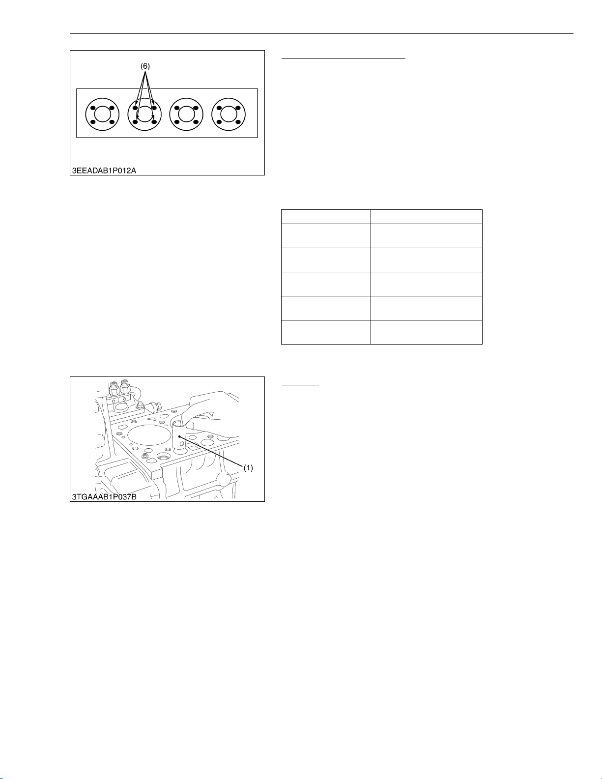
03-M-DI Series, WSM
KiSC issued 10, 2009 A
DIESEL ENGINE
Cylinder Head (Continued)
IMPORTANTQ
• When replacing piston, piston pin, small end bushing,
connecting rod, or crankpin bearings, measure piston
head’s protrusion or recessing from the level of crankcase
cylinder face (average of 4 pistons) after installing the
pistons, and select the cylinder head gasket following the
below table.
Selecting the cylinder head gasket
1. Measure the piston head’s protrusion or recessing from the
crankcase cylinder face 4 spots per each piston (average of four
pistons) using the dial gauge.
2. Select the suitable cylinder need gasket refer to the table below.
Gasket Size (Number) Piston Protrusion
15
20
25
30
35
0.475 to 0.525 mm
0.0187 to 0.0207 in.
0.525 to 0.575 mm
0.0207 to 0.0226 in.
0.575 to 0.625 mm
0.0226 to 0.0246 in.
0.625 to 0.675 mm
0.0246 to 0.0266 in.
0.675 to 0.725 mm
0.0266 to 0.0285 in.
(6) Measuring Points
W1085632
Tappets
1. Remove the tappets (1) from the crankcase.
(When reassembling)
• Visually check the contact between tappets (1) and cams for
proper rotation. If defect is found, replace tappets.
• Before installing the tappets (1), apply engine oil thinly around
them.
IMPORTANTQ
• Do not change the combination of tappet (1) and tappet
guide of the crankcase.
(1) Tappet
W1022001
S-47
Page 69
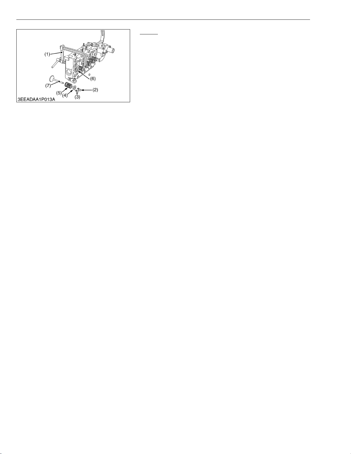
03-M-DI Series, WSM
KiSC issued 10, 2009 A
DIESEL ENGINE
Valves
1. Remove the valve caps (2).
2. Remove the valve spring collet (3), pushing the valve spring
retainer (4) by valve spring replacer (1).
3. Remove the valve spring retainer (4), valve spring (5) and valve
stem seal (6).
4. Remove the valve (7).
(When reassembling)
• Wash the valve stem and valve guide hole, and apply engine oil
sufficiently.
• After installing the valve spring collets (3), lightly tap the stem to
assure proper fit with a plastic hammer.
IMPORTANTQ
• Do not change the combination of valve and valve guide
hole.
(1) Valve Spring Replacer
(2) Valve Cap
(3) Valve Spring Collet
(4) Valve Spring Retainer
(5) Valve Spring
(6) Valve Stem Seal
(7) Valve
W1022102
S-48
Page 70
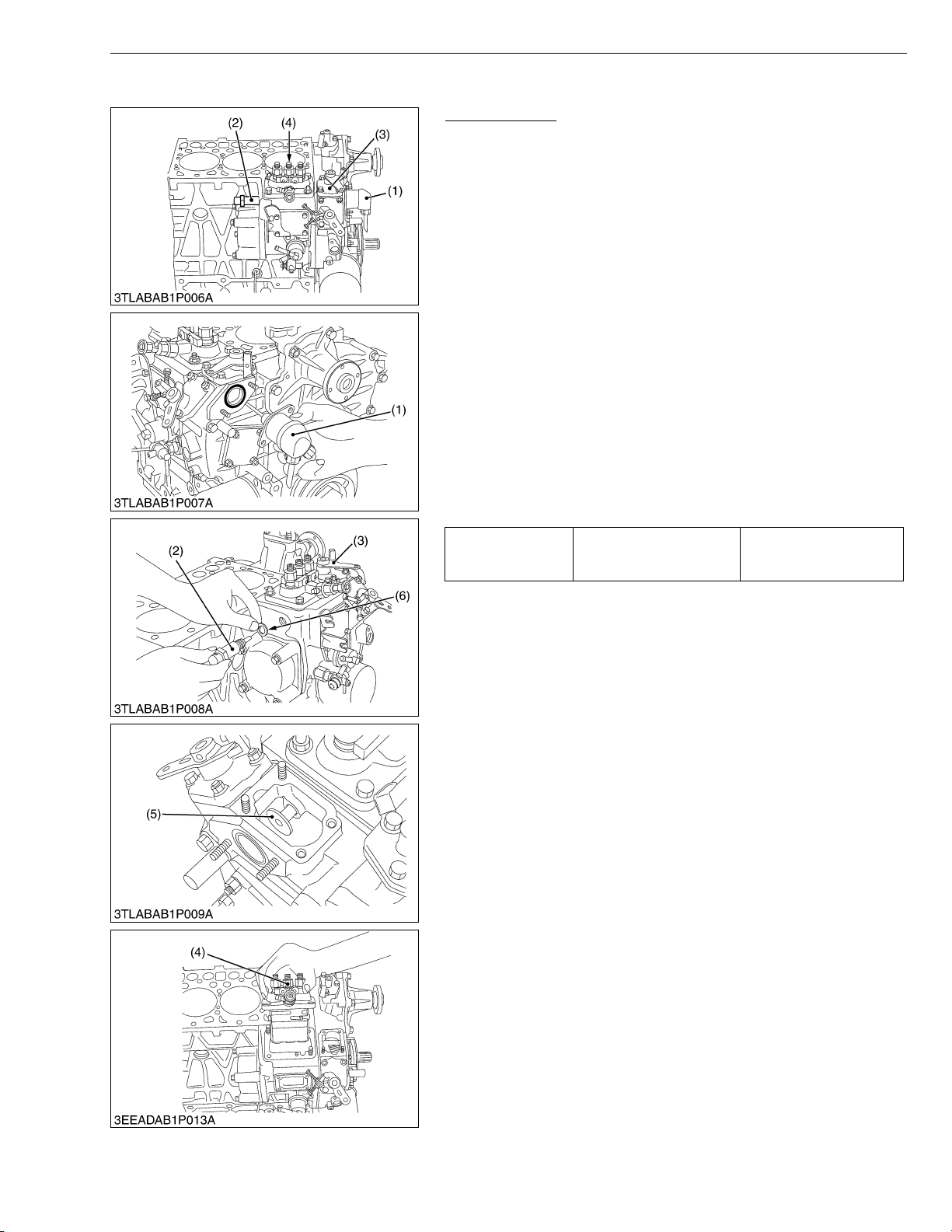
03-M-DI Series, WSM
KiSC issued 10, 2009 A
(4) Timing Gears, Camshaft and Fuel Camshaft
Injection Pump
1. Remove the stop solenoid (1) and hi-idling body (2).
2. Remove the engine stop lever (3) and stop solenoid guide (5).
3. Remove the fuel injection pump assembly (4).
IMPORTANTQ
• Before removing the injection pump assembly (4), be sure to
remove the stop solenoid (1), hi-idling body (2), engine stop
lever (3) and stop solenoid guide (5).
(When reassembling)
• Before attaching the stop solenoid (1), hi-idling body (2) and stop
solenoid guide (5), install the injection pump first into position.
• Replace the hi-idling body gasket (6) with a new one.
• Before fitting the stop lever (3) to the gear case, install the stop
solenoid guide (5) first into position. Then attach the stop lever
and use it to see if it functions well.
• Before fitting the idling limiter in place, attach the stop solenoid
guide (5) and the engine stop lever (3) in their respective
positions.
• When installing the stop solenoid (1), be careful to keep the Oring in place.
• Be sure to insert the push rod of the stop solenoid into the hole
at the center of the solenoid guide (5).
Tightening torque Hi-idling body
DIESEL ENGINE
44.1 to 49.0 N·m
4.5 to 5.0 kgf·m
32.6 to 36.3 ft-lbs
(1) Stop Solenoid
(2) Hi-idling Body
(3) Stop Lever
(4) Injection Pump Assembly
(5) Stop Solenoid Guide
(6) Hi-idling Body Gasket
W1023686
S-49
Page 71
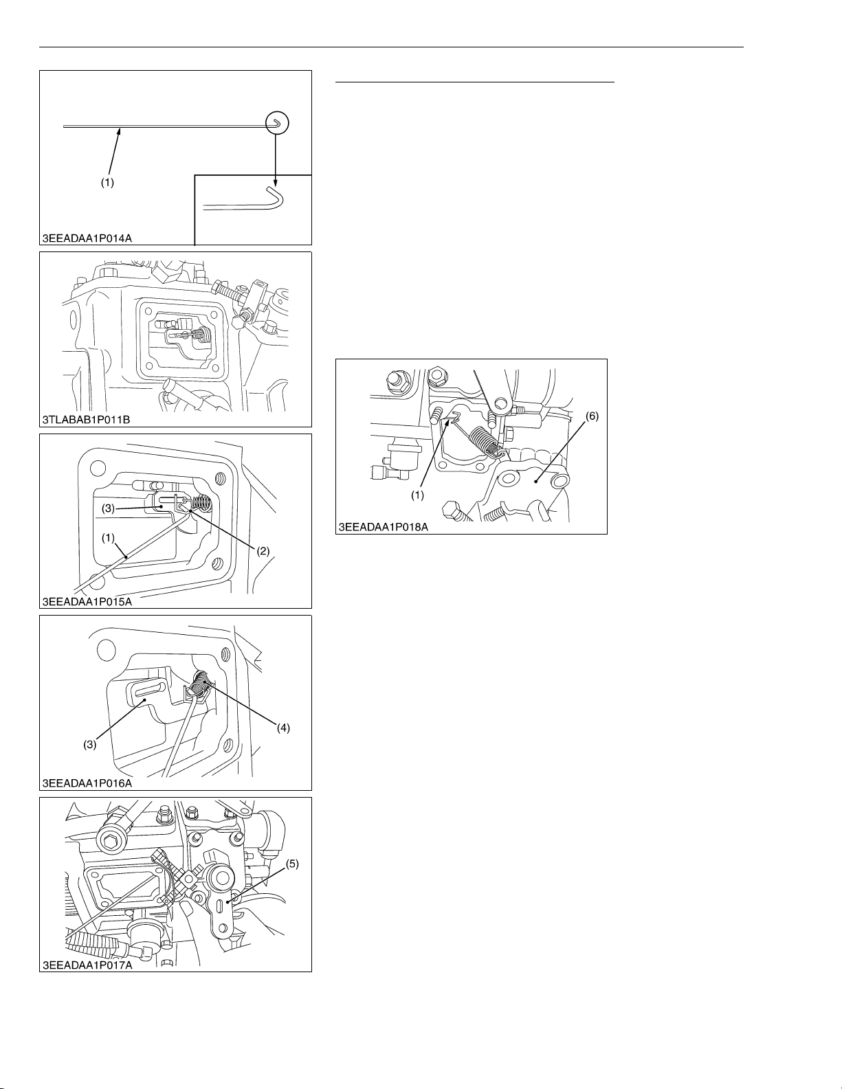
03-M-DI Series, WSM
KiSC issued 10, 2009 A
DIESEL ENGINE
Governor Springs and Speed Control Plate
NOTEQ
• Specific tool (1) :
1.2 mm diameter hard wire with its end hooked, overall
length 200 mm (7.87 in.).
The tip of wire is bent like the hook to hang governor
springs.
1. Remove the injection pump cover.
2. Remove the speed control plate (6) mounting nuts and bolts.
3. Using the specific tool (1), undo the large governor spring (2)
from the fork lever (3).
4. Using the specific tool (1), undo the small governor spring (4)
from the fork lever (3).
5. Set the speed control lever (5) as the figure.
6. Take out the speed control plate (6) with care not to let the large
(2) and small (4) governor springs come off this plate and fall in
to the gear case.
(1) Specific Tool
(2) Large Governor Spring
(3) Fork Lever
(4) Small Governor Spring
(5) Speed Control Lever
(6) Speed Control Plate
W1148604
S-50
Page 72
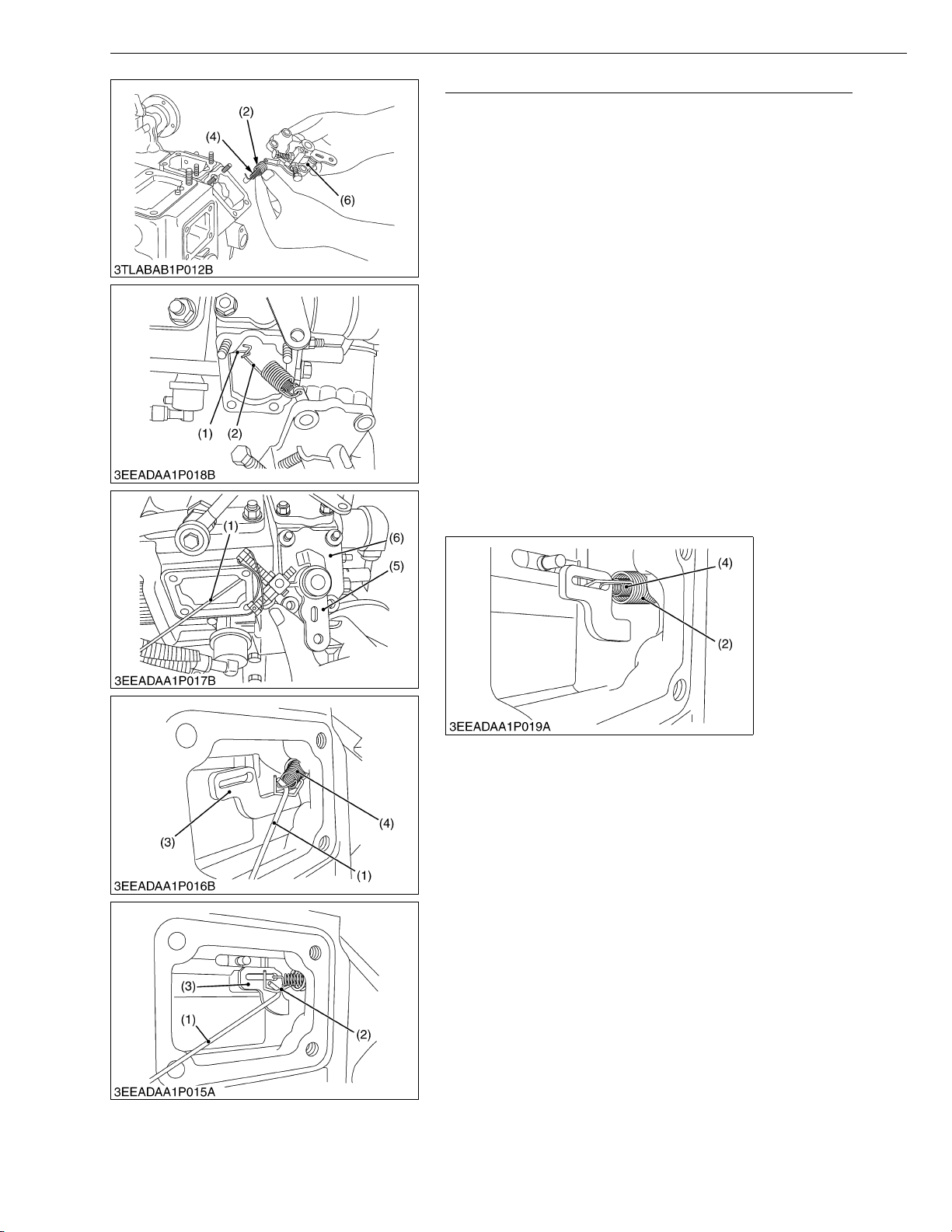
03-M-DI Series, WSM
KiSC issued 10, 2009 A
DIESEL ENGINE
Governor Springs and Speed Control Plate (Continued)
(When reassembling)
• Hook the small spring (4) first and then the large governor spring
(2) on the speed control plate (6).
• Put the specific tool (1) from the injection pump side to catch the
large governor spring (2). Keep this spring slightly extended and
place the speed control plate (6) in its specified position.
• Using the specific tool (1), hook the small governor spring (4)
onto the fork lever (3).
NOTEQ
• Be careful not to stretch the small governor spring (4) too
long because otherwise it may get deformed permanently.
• Using the specific tool (1), hook the large governor spring (2)
onto the fork lever (3).
• Make sure both the governor springs (2), (4) are tight on the
fork lever (3).
• Apply and tighten up the two bolts and two nuts on the
speed control plate (6).
• Check that the speed control lever (5) positions low idle,
after assembling governor springs.
• Check that the speed control lever (5) returns to the high idle
position rather than the low idle position, after moving the
lever to the maximum speed position.
• Finally attach the injection pump cover in position.
(1) Specific Tool
(2) Large Governor Spring
(3) Fork Lever
(4) Small Governor Spring
(5) Speed Control Lever
(6) Speed Control Plate
W1152334
S-51
Page 73
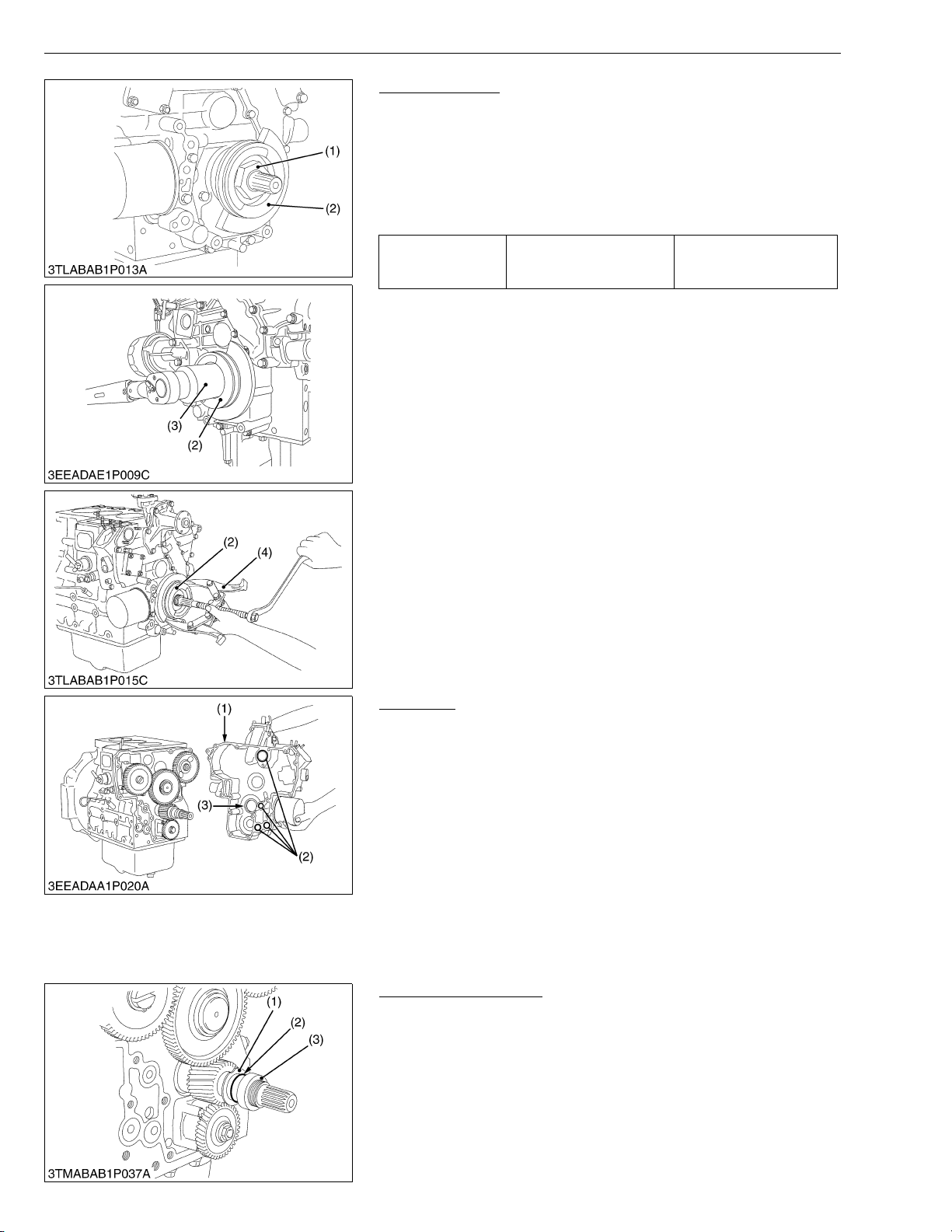
03-M-DI Series, WSM
KiSC issued 10, 2009 A
DIESEL ENGINE
Fan Drive Pulley
1. Lock the flywheel not to turn using the flywheel stopper.
2. Remove the fan drive pulley mounting nut (1) using 46 mm deep
socket wrench (3).
3. Remove the fan drive pulley (2) with gear puller (4).
4. Remove the feather key.
(When reassembling)
• Apply grease to the splines of coupling.
137.3 to 156.9 N·m
14.0 to 16.0 kgf·m
101.3 to 115.7 ft-lbs
Tightening torque
Fan drive pulley mounting
nut
(1) Nut
(2) Fan Drive Pulley
(3) 46 mm Deep Socket Wrench
(4) Gear Puller
W1024348
Gear Case
1. Remove the hour meter gear case (if equipped).
2. Remove the gear case (1).
3. Remove the O-rings (2).
(When reassembling)
• Apply liquid gasket (Three Bond 1215 or equivalent) to both side
of hour meter gear case gasket (if equipped).
• Check to see if there are four O-rings (2) inside the gear case (1).
• Apply a thin film of engine oil to the oil seal (3), and install it,
noting the lip come off.
• Before installing the gear case gasket, apply a non-drying
adhesive.
(1) Gear Case
(2) O-ring
(3) Oil Seal
W1024531
Crankshaft Oil Slinger
1. Remove the crankshaft collar (3).
2. Remove the O-ring (2).
3. Detach the crankshaft oil slinger (1).
(When reassembling)
• Insert the crankshaft collar (3) after install the gear case to
cylinder body.
(1) Crankshaft Oil Slinger
(2) O-ring
(3) Crankshaft Collar
W1024731
S-52
Page 74
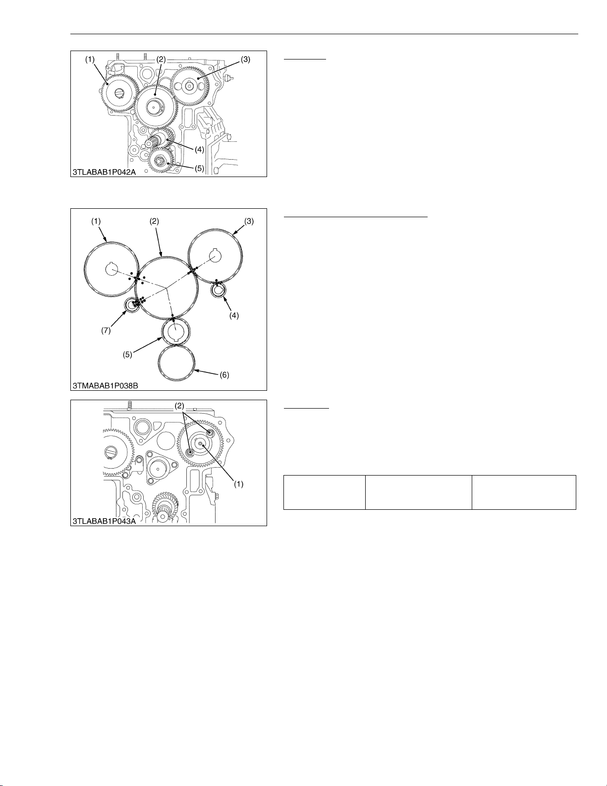
03-M-DI Series, WSM
KiSC issued 10, 2009 A
DIESEL ENGINE
Idle Gear
1. Remove the external snap ring.
2. Detach the idle gear collar.
3. Detach the idle gear (2).
(When reassembling)
• Check to see each gear is aligned with its aligning mark
- Idle gear (2) and crank gear (4)
- Idle gear (2) and cam gear (3)
- Idle gear (2) and injection pump gear (1)
(1) Injection Pump Gear
(2) Idle Gear
(3) Cam Gear
(4) Crank Gear
(5) Oil Pump Drive Gear
W1024941
Idle Gear (For Balancer Model)
1. Remove the external snap ring.
2. Detach the idle gear collar.
3. Detach the idle gear (2).
(When reassembling)
• Check to see each gear is aligned with its aligning mark:
- Idle gear (2) and crank gear (5), cam gear (3) and balancer
gear (4)
- Cam gear (3) and idle gear (2)
- Idle gear (2) and injection pump gear (1)
- Idle gear (2) and balancer gear (7)
(1) Injection Pump Gear
(2) Idle Gear
(3) Cam Gear
(4) Balancer Gear
(5) Crank Gear
(6) Oil Pump Drive Gear
(7) Balancer Gear
W1097988
Camshaft
1. Remove the camshaft set screws (2) and draw out the camshaft
(1).
(When reassembling)
• When installing the idle gear, be sure to align the alignment
marks on gears.
23.5 to 27.5 N·m
Tightening torque Camshaft set screw
2.4 to 2.8 kgf·m
17.4 to 20.3 ft-lbs
(1) Camshaft (2) Camshaft Set Screw
W1025098
S-53
Page 75
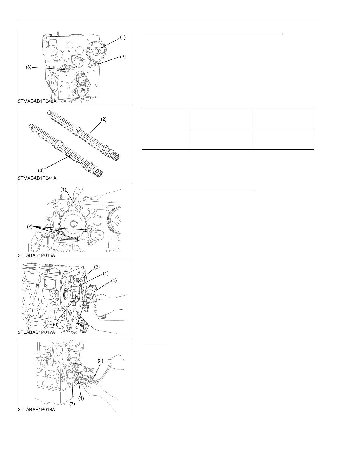
03-M-DI Series, WSM
KiSC issued 10, 2009 A
DIESEL ENGINE
Camshaft and Balancer Shaft (For Balancer Model)
1. Remove the camshaft set bolts and draw out the camshaft (1).
2. Remove the balancer shaft 1 (2) set bolts and draw out the
balancer shaft 1 (2).
3. Remove the balancer shaft 2 (3) set bolts and draw out the
balancer shaft 2 (3).
(When reassembling)
• When install the balancer shaft 1 (2) and 2 (3), be sure to place
the 1st and 4th cylinders piston at the top dead center in
compression then, align all mating marks on each gear to
assemble the timing gears, set the idle gear last.
23.5 to 27.5 N·m
Camshaft set bolt
Tightening torque
Balancer shaft set bolt
2.4 to 2.8 kgf·m
17.4 to 20.3 ft-lbs
23.5 to 27.5 N·m
2.4 to 2.8 kgf·m
17.4 to 20.3 ft-lbs
(1) Camshaft
(2) Balancer Shaft 1
(3) Balancer Shaft 2
W1099079
Fuel Camshaft and Fork Lever Assembly
1. Remove the fuel feed pump.
2. Detach the fuel camshaft stopper (1).
3. Remove the three fork lever holder mounting screws (2).
4. Draw out the fuel camshaft assembly (5), (6) and fork lever
assembly (3), (4), (7) at the same time.
(When reassembling)
• After installation, check to see that the fork lever 1 (3) and 2 (4)
are fixed to the fork lever shaft, and that they can turn smoothly
in the holder (7).
(1) Fuel Camshaft Stopper
(2) Fork Lever Holder Mounting Screws
(3) Fork Lever 1
(4) Fork Lever 2
(5) Injection Pump Gear
(6) Fuel Camshaft
(7) Fork Lever Holder
W1025309
Oil Pump
1. Remove the nut.
2. Draw out the oil pump drive gear (1) with gear puller (2).
3. Remove the four oil pump mounting screws. Detach the oil pump
(3).
(1) Oil Pump Drive Gear
(2) Gear Puller
(3) Oil Pump
W1025581
S-54
Page 76
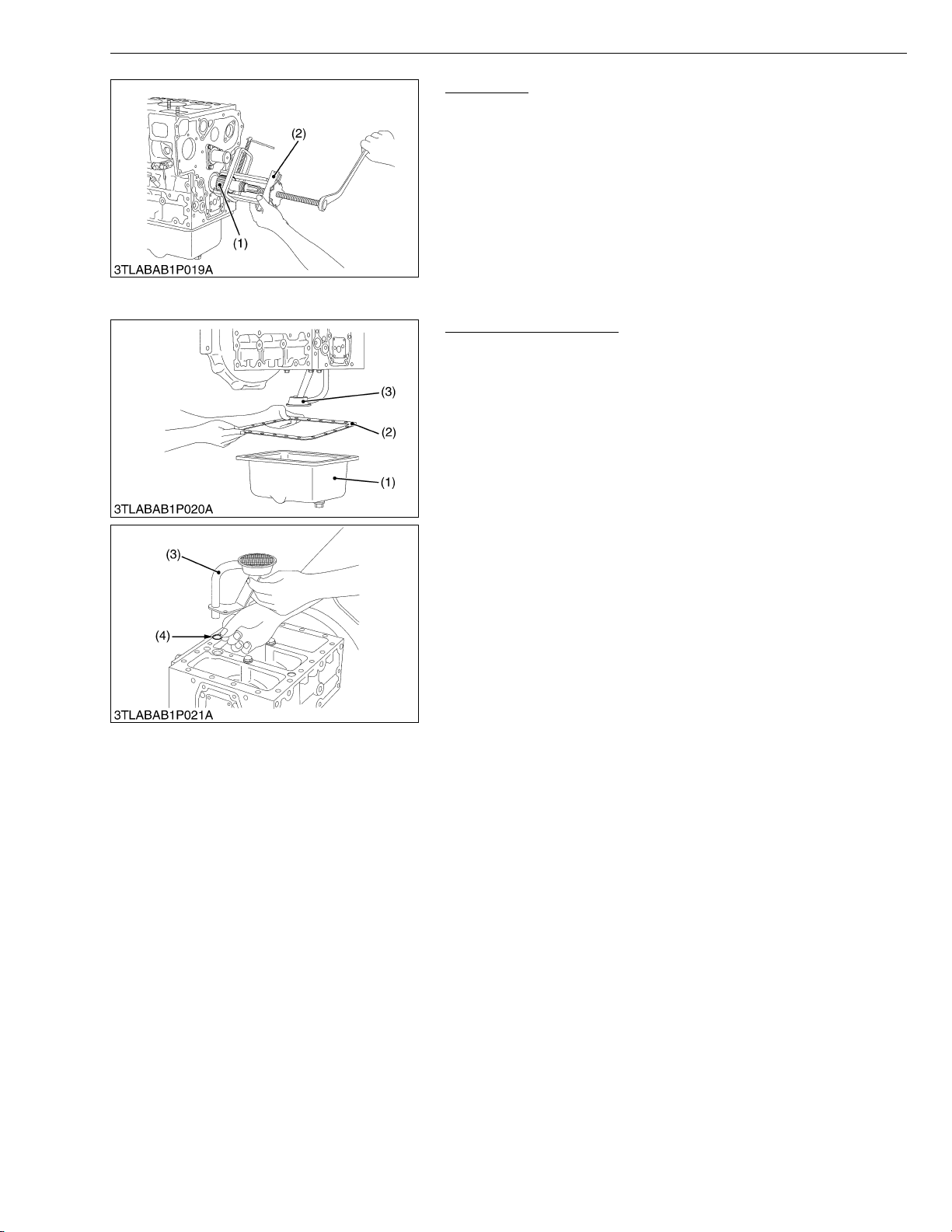
03-M-DI Series, WSM
KiSC issued 10, 2009 A
(5) Piston and Connecting Rod
DIESEL ENGINE
Crank Gear
1. Draw out the crank gear (1) with a puller (2).
2. Remove the feather key.
(1) Crank Gear (2) Gear Puller
W1025476
Oil Pan and Oil Strainer
1. Remove the oil pan mounting screws.
2. Remove the oil pan (1) by lightly tapping the rim of the pan with
a wooden hammer.
3. Remove the oil pan gasket (2).
4. Remove the oil strainer (3) and O-ring (4).
(When reassembling)
• After cleaning the oil strainer (3), check to see that the filter mesh
in clean, and install it.
• Visually check the O-ring (4), apply engine oil, and install it.
• Securely fit the O-ring (4) to the oil strainer (3).
• Apply a liquid gasket (Three Bond 1215 or equivalent) to the oil
pan side of the oil pan gasket (2).
• To avoid uneven tightening, tighten oil pan mounting screws in
diagonal order from the center.
(1) Oil Pan
(2) Oil Pan Gasket
(3) Oil Strainer
(4) O-ring
W1025687
S-55
Page 77
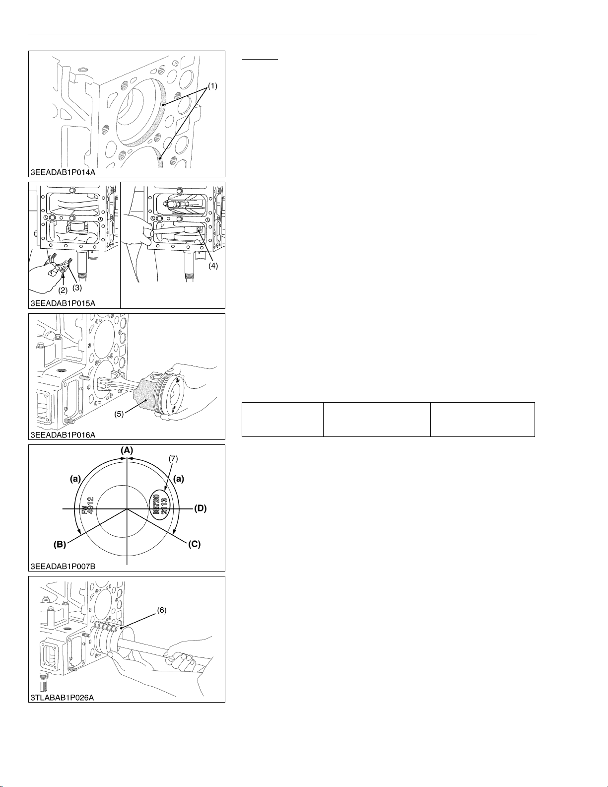
03-M-DI Series, WSM
KiSC issued 10, 2009 A
DIESEL ENGINE
Pistons
1. Completely clean carbon (1) in the cylinders.
2. Remove the connecting rod cap (3).
3. Turn the flywheel and bring the piston to top dead center.
4. Draw out the piston upward by lightly tapping it from the bottom
of the crankcase with the grip of a hammer.
5. Draw out the other piston in the same method as above.
(When reassembling)
• Before inserting piston into the cylinder, apply enough engine oil
to the piston.
• When inserting the piston into the cylinder, face the mark on the
connecting rod to the injection pump.
IMPORTANTQ
• Do not change the combination of cylinder and piston. Make
sure of the position of each piston by marking. For example,
mark “1” on the No. 1 piston.
• Place the piston rings with their gaps at 2.09 rad (120 °) from
the piston pin’s direction as shown in the figure.
• Carefully insert the pistons using a piston ring compressor
(6).
• When inserting the piston in place, be careful not to get the
molybdenum disulfide coating torn off its skirt. This coating
is useful in minimizing the clearance with the cylinder liner.
Just after the piston pin has been press-fitted, in particular,
the piston is still hot and the coating is easy to peel off. Wait
until the piston cools down.
• When replacing the piston, look at the code number (7)
marked on top of the piston. Use a replacement piston with
the same code number.
44.1 to 49.0 N·m
Tightening torque Connecting rod screw
4.5 to 5.0 kgf·m
32.5 to 36.2 ft-lbs
(1) Carbon
(2) Connecting Rod Screw
(3) Connecting Rod Cap
(4) Connecting Rod
(5) Molybdenum Disulfide Coating in
Piston Skirt
(6) Piston Ring Compressor
(7) Code Number
(A) Top Ring Gap
(B) Second Ring Gap
(C) Oil Ring Gap
(D) Piston Pin Hole
(a) 2.09 rad (120 °)
W1026141
S-56
Page 78
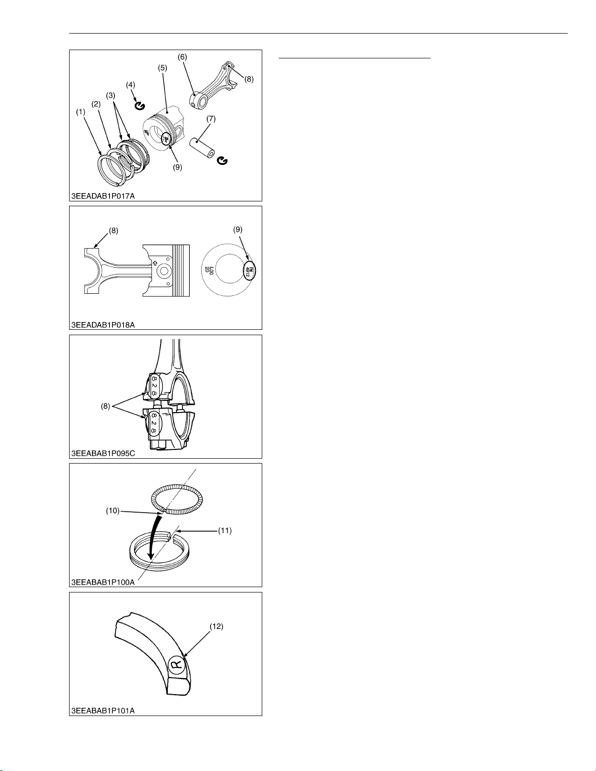
03-M-DI Series, WSM
KiSC issued 10, 2009 A
DIESEL ENGINE
Piston Ring and Connecting Rod
1. Remove the piston rings (1), (2), (3) using a piston ring tool (Code
No. 07909-32121).
2. Remove the piston pin (7), and separate the connecting rod (6)
from the piston (5).
(When reassembling)
• When installing the ring, assemble the rings so that the
manufacturer’s mark (12) near the gap faces the top of the piston
(5).
• When installing the oil ring (3) onto the piston (5), place the
expander joint (10) on the opposite side of the oil ring gap (11).
• Apply engine oil to the piston pin (7).
• When installing the connecting rod (6) to the piston (5), immerse
the piston (5) in 80 °C (176 °F) oil for 10 to 15 minutes and insert
the piston pin (7) to the piston (5).
NOTEQ
• Assemble the piston (5) to the connecting rod (6) with the
FW mark (9) facing the flywheel side and the connecting rod
mark (8) facing the injection pump side.
• Mark the same number on the connecting rod (6) and the
piston (5) so as not to change the combination.
(1) Top Ring
(2) Second Ring
(3) Oil Ring
(4) Piston Pin Snap Ring
(5) Piston
(6) Connecting Rod
(7) Piston Pin
(8) Mark
(9) FW Mark
(10) Expander Joint
(11) Oil Ring Gap
(12) Manufacturer’s Mark
W1026376
S-57
Page 79
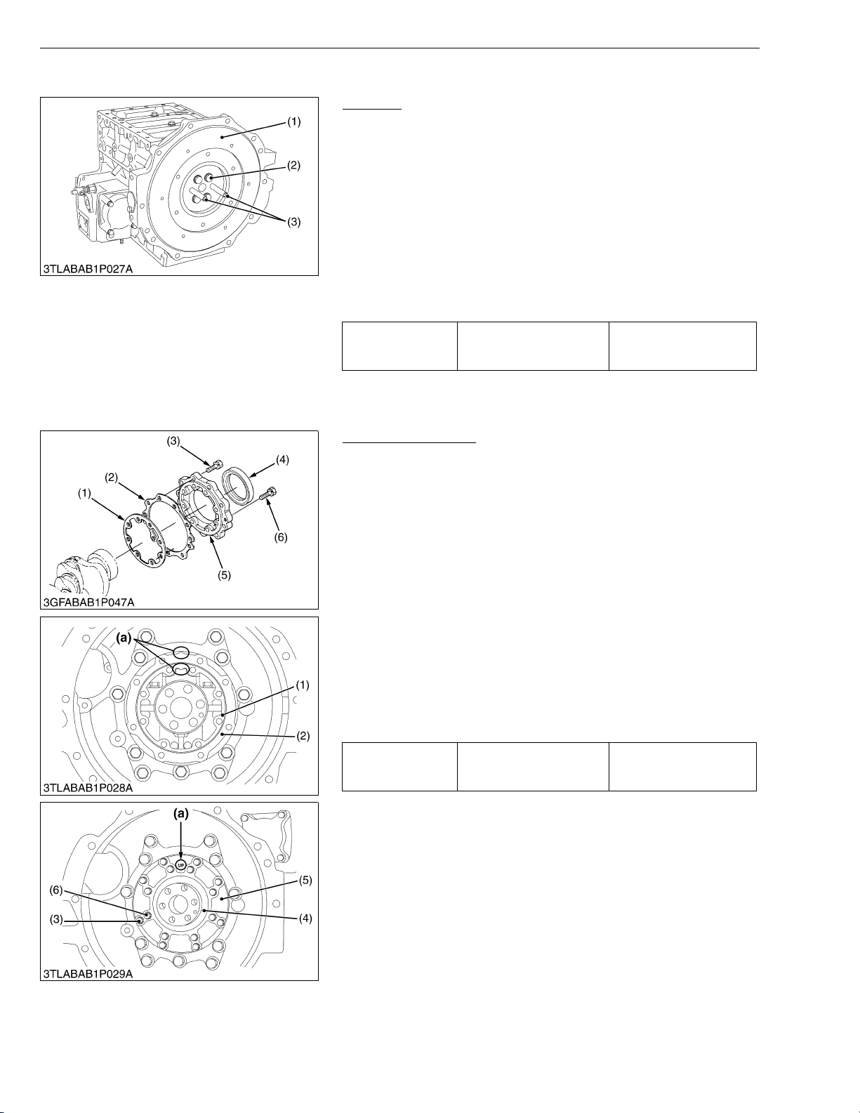
03-M-DI Series, WSM
KiSC issued 10, 2009 A
(6) Crankshaft
DIESEL ENGINE
Flywheel
1. Fit the stopper to the flywheel (1).
2. At first, remove two pieces of the flywheel screws (2).
3. Insert two pieces of the flywheel guide screws (3) in the holes.
4. Remove the all flywheel screws (2).
5. Remove the flywheel (1) slowly along the flywheel guide screws
(3).
(When reassembling)
• Insert two pieces of the flywheel guide screws (3).
• Check to see that there are no metal particles left on the flywheel
mounting surfaces.
• Apply engine oil to the threads and the undercut surface of the
flywheel bolt and fit the bolt.
Tightening torque Flywheel screws
98.0 to 107.8 N·m
10.0 to 11.0 kgf·m
72.3 to 79.5 ft-lbs
(1) Flywheel
(2) Flywheel Screw
(3) Flywheel Guide Screws
W1026863
Bearing Case Cover
1. Remove the bearing case cover mounting screws. First, remove
inside screws (6) and then outside screws (3).
2. Screw two removed screws into the screw hole of bearing case
cover (5) to remove it.
IMPORTANTQ
• The length of inside screws (6) and outside screws (3) are
different. Do not take a mistake using inside screws and
outside screws.
(When reassembling)
• Fit the bearing case gasket (1) and the bearing case cover gasket
(2) with correct directions.
• Install the bearing case cover (5) to position the casting mark
“UP” on it upward.
• Apply engine oil to the oil seal lip and take care that it is not rolled
when installing.
• Tighten the bearing case cover mounting screws with even force
on the diagonal line.
23.5 to 27.5 N·m
2.4 to 2.8 kgf·m
17.4 to 20.3 ft-lbs
Tightening torque
Bearing case cover
mounting screw
(1) Bearing Case Gasket
(2) Bearing Case Cover Gasket
(3) Bearing Case Cover Mounting Screw
(4) Oil Seal
S-58
(5) Bearing Case Cover
(6) Bearing Case Cover Mounting Screw
(a) Upside
W10292140
Page 80
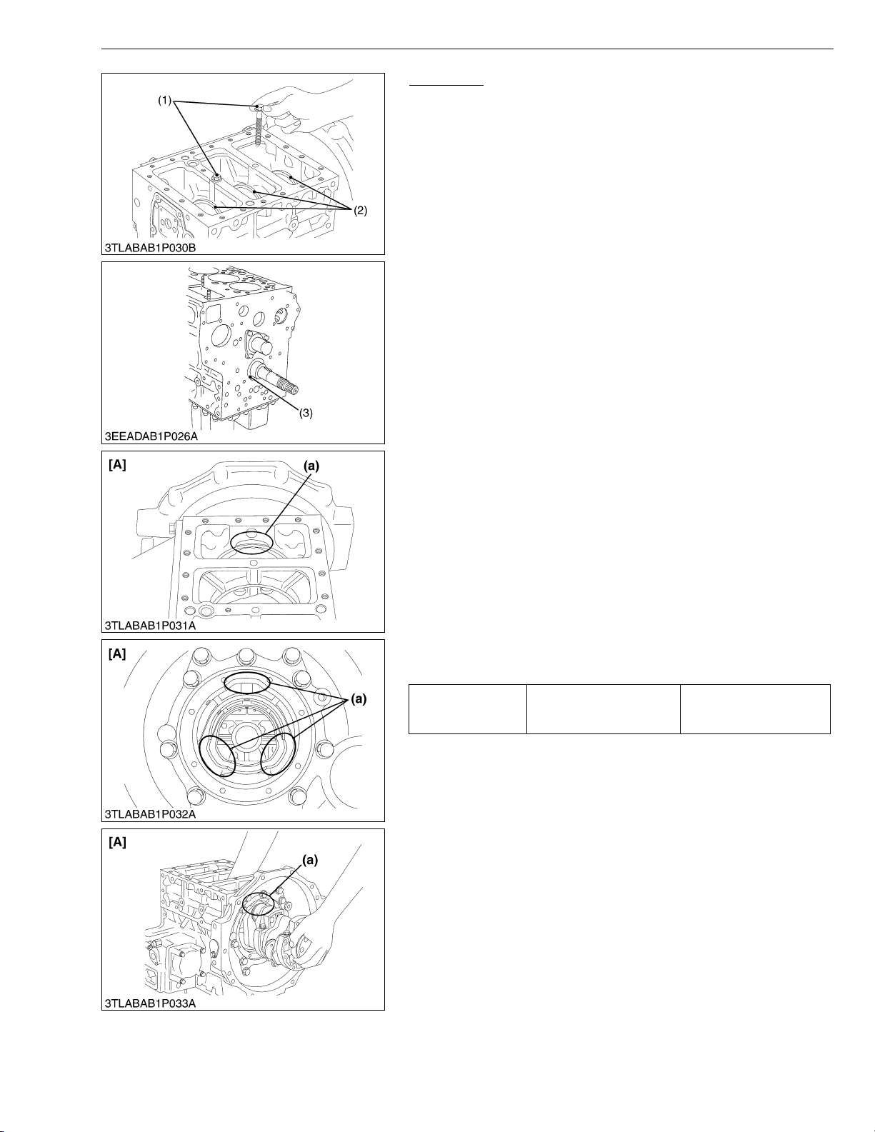
03-M-DI Series, WSM
KiSC issued 10, 2009 A
DIESEL ENGINE
Crankshaft
NOTEQ
• Before disassembling, check the side clearance of
crankshaft. Also check it during reassembling.
For D1503-M-DI, D1503-M-DI-T, D1703-M-DI and V2203-M-DI
1. Remove the main bearing case screw 2 (1).
2. Pull out the crankshaft assembly, taking care not to damage the
crankshaft bearing 1 (3).
For D1803-M-DI
1. Remove the main bearing case screw 2 (1).
2. Turn the crankshaft to set the crank pin of the third cylinder to the
bottom dead center. Then draw out the crankshaft until the crank
pin of the second cylinder comes to the center of the third
cylinder.
3. Turn the crankshaft by 2.09 rad (120 °) counterclockwise to set
the crank pin of the second cylinder to the bottom dead center.
Draw out the crankshaft until the crank pin of the first cylinder
comes to the center of the third cylinder
4. Repeat the above steps to draw out all the crankshaft.
For V2403-M-DI
1. Remove the main bearing case screw 2 (1).
2. Turn the crankshaft to set the crank pin of the 4th cylinder to the
horizontal directions (Right or Left). Then draw out all the
crankshaft, holding the crank pins to the horizontal directions
(Right or Left).
(When reassembling)
IMPORTANTQ
• Install the crankshaft sub assembly, aligning the screw hole
of main bearing case 2 (2) with the screw hole of cylinder
block.
• When tightening the main bearing case screw 2 (1), apply oil
to the screw and screw by hand before tightening the
specific torque.
If not smooth to screw by hand, align the screw holes
between the cylinder block and the main bearing case.
68.6 to 73.5 N·m
7.0 to 7.5 kgf·m
50.6 to 54.2 ft-lbs
Tightening torque
Main bearing case screws
2
(1) Main Bearing Case Screw 2
(2) Main Bearing Case 2
(3) Crankshaft Bearing 1
S-59
(a) Cut place for removing and
installing the crankshaft
[A] D1803-M-DI
W1066311
Page 81
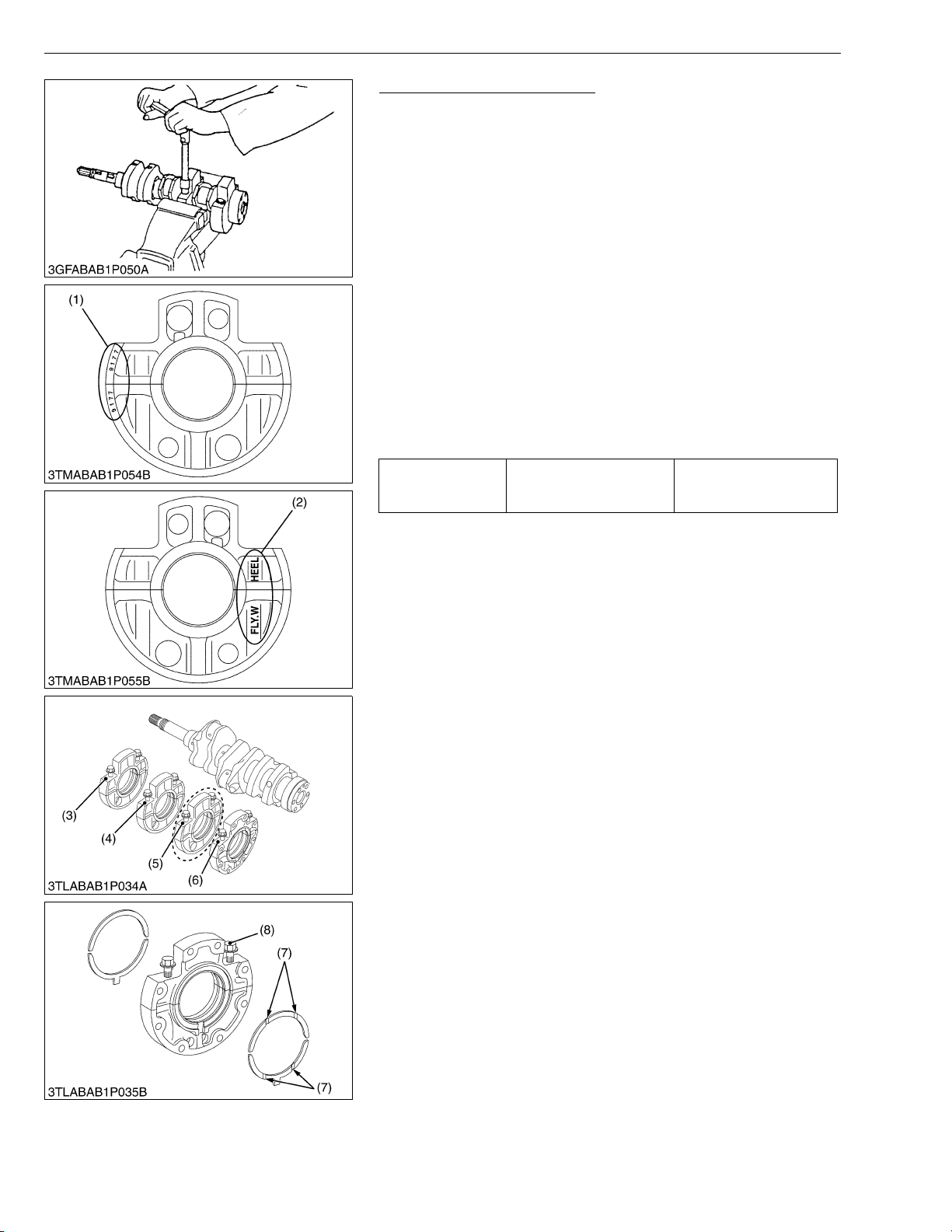
03-M-DI Series, WSM
KiSC issued 10, 2009 A
DIESEL ENGINE
Main Bearing Case Assembly
1. Remove the two main bearing case screws 1 (8), and remove the
main bearing case assembly being careful with thrust bearing
and crankshaft bearing.
2. Remove the main bearing case 1, 2 as above.
(When reassembling)
• Clean the oil passage in the main bearing case.
• Apply clean engine oil on the bearings.
• Install the main bearing case assemblies in the original positions.
Since diameters of main bearing cases vary, install them in order
of makings (A, B for 3 cylinders and A, B, C for 4 cylinders) from
the gear case side.
• Match the alignment numbers (1) and mark (2) on the main
bearing case.
• When installing the main bearing case 1 and 2, face the mark
“FLYWHEEL” to the flywheel.
• Install the thrust bearing with its oil groove facing (7) outward.
• Confirm that the main bearing case moves smoothly after
tightening the main bearing case screw 1 (8) to the specified
torque.
Tightening torque Main bearing case screw 1
46.1 to 50.9 N·m
4.7 to 5.2 kgf·m
34.0 to 37.6 ft-lbs
(1) Alignment Number
(2) Alignment Mark
(3) A
(4) B
(5) C
(6) No Mark
(7) Oil Groove
(8) Main Bearing Case Screw 1
W1027366
S-60
Page 82
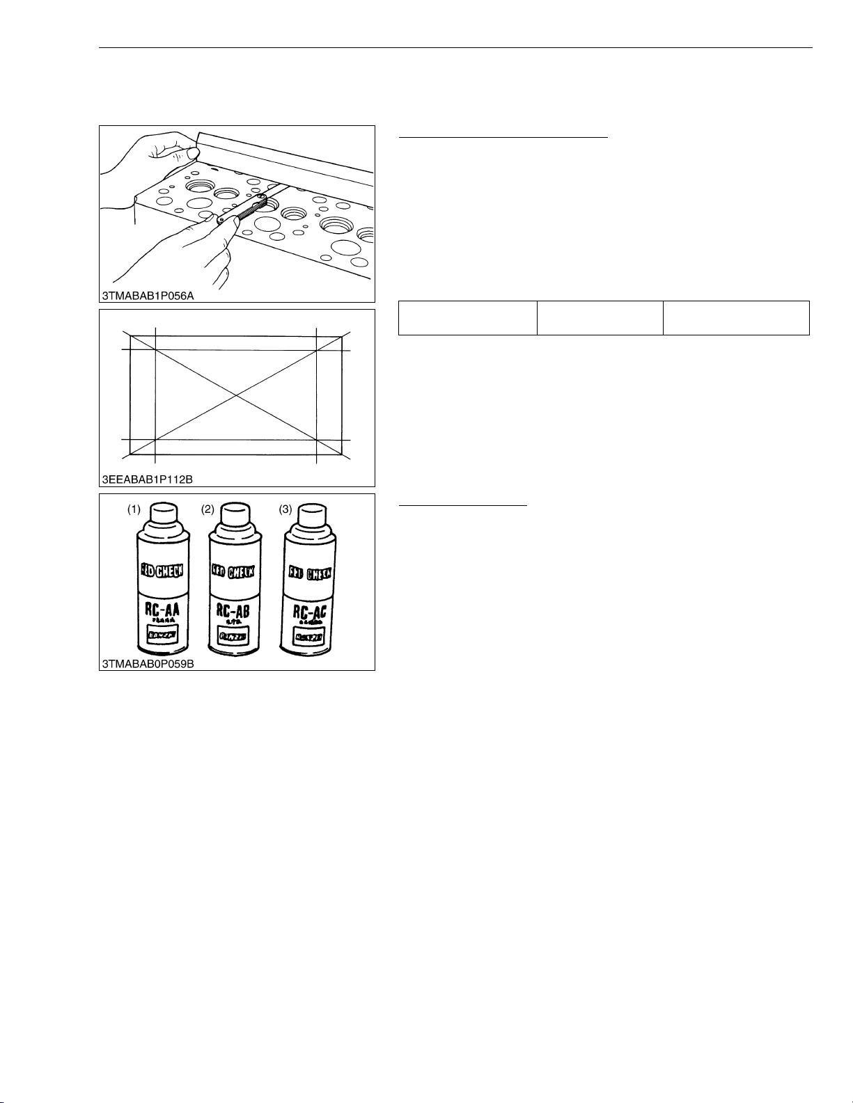
03-M-DI Series, WSM
KiSC issued 10, 2009 A
[3] SERVICING
(1) Cylinder Head and Valves
DIESEL ENGINE
Cylinder Head Surface Flatness
1. Clean the cylinder head surface.
2. Place a straightedge on the cylinder head’s four sides and two
diagonal as shown in the figure.
3. Measure the clearance with a feeler gauge.
4. If the measurement exceeds the allowable limit, correct it with a
surface grinder.
IMPORTANTQ
• Do not place the straightedge on the combustion chamber.
• Be sure to check the valve recessing after correcting.
Cylinder head surface
flatness
Factory spec.
0.05 mm / 500 mm
0.0020 in. / 19.69 in.
W1027737
Cylinder Head Flaw
1. Prepare an air spray red check (Code No. 07909-31371).
2. Clean the surface of the cylinder head with detergent (2).
3. Spray the cylinder head surface with the red permeative liquid
(1). Leave it five to ten minutes after spraying.
4. Wash away the read permeative liquid on the cylinder head
surface with the detergent (2).
5. Spray the cylinder head surface with white developer (3).
6. If flawed, it can be identified as red marks.
(1) Red Permeative Liquid
(2) Detergent
(3) White Developer
W1076542
S-61
Page 83
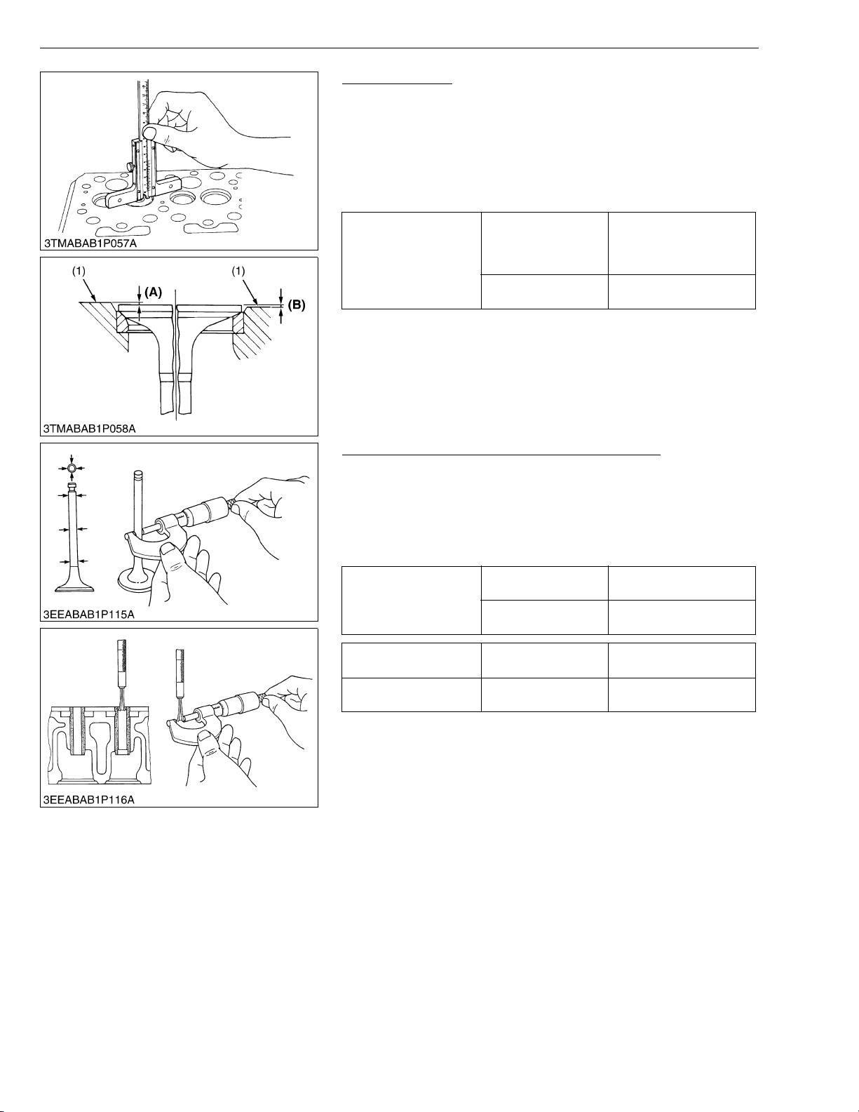
03-M-DI Series, WSM
KiSC issued 10, 2009 A
DIESEL ENGINE
Valve Recessing
1. Clean the cylinder head surface (1), valve face and valve seat.
2. Insert the valve into the valve guide.
3. Measure the valve recessing with a depth gauge.
4. If the measurement exceeds the allowable limit, replace the
valve.
5. If it still exceeds the allowable limit after replacing the valve,
replace the cylinder head.
0.65 (protrusion) to
Factory spec.
Valve recessing
Allowable limit
(1) Cylinder Head Surface (A) Recessing
(B) Protrusion
0.85 (recessing) mm
0.026 (protrusion) to
0.033 (recessing) in.
1.20 (recessing) mm
0.0472 (recessing) in.
W1076880
Clearance between Valve Stem and Valve Guide
1. Remove carbon from the valve guide section.
2. Measure the valve stem O.D. with an outside micrometer.
3. Measure the valve guide I.D. with a small hole gauge, and
calculate the clearance.
4. If the clearance exceeds the allowable limit, replace the valves.
If it still exceeds the allowable limit, replace the valve guide.
Clearance between
valve stem and guide
Valve stem O.D. Factory spec.
Valve guide I.D. Factory spec.
Factory spec.
Allowable limit
0.040 to 0.070 mm
0.0016 to 0.0028 in.
0.1 mm
0.0039 in.
7.960 to 7.975 mm
0.31339 to 0.314398 in.
8.015 to 8.030 mm
0.31555 to 0.31614 in.
W1077495
S-62
Page 84
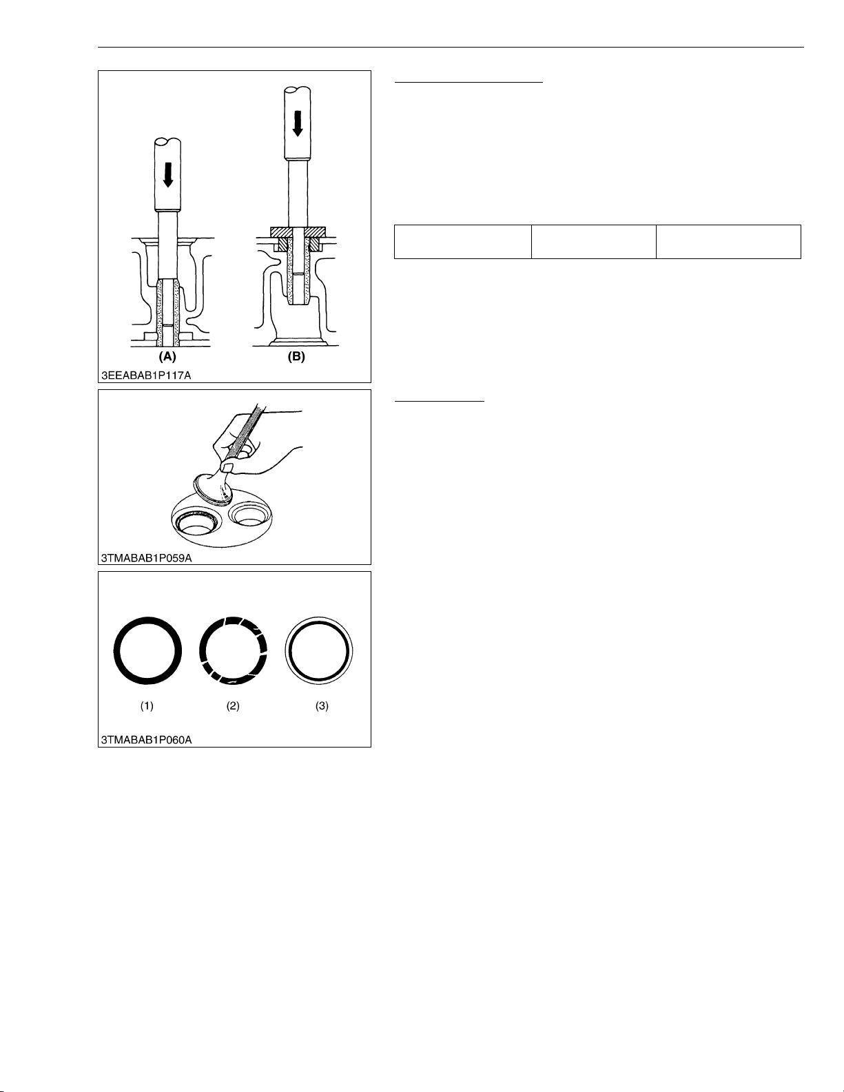
03-M-DI Series, WSM
KiSC issued 10, 2009 A
DIESEL ENGINE
Replacing Valve Guide
(A) (When removing)
1. Press out the used valve guide using a valve guide replacing tool.
(B) (When installing)
1. Clean a new valve guide and valve guide bore, and apply engine
oil to them.
2. Press in a new valve guide using a valve guide replacing tool.
3. Ream precisely the I.D. of the valve guide to the specified
dimension.
Valve guide I.D.
(Intake and exhaust)
Factory spec.
8.015 to 8.030 mm
0.31555 to 0.31614 in.
IMPORTANTQ
• Do not hit the valve guide with a hammer during
replacement.
(A) When Removing (B) When Installing
W1027889
Valve Seating
1. Coat the valve face lightly with prussian blue and put the valve on
its seat to check the contact.
2. If the valve does not seat all the way around the valve seat or the
valve contact is less than 70 %, correct the valve seating as
follows.
3. If the valve contact does not comply with the reference value,
replace the valve or correct the contact of valve seating.
(1) Correct
(2) Incorrect
(3) Incorrect
W1028219
S-63
Page 85
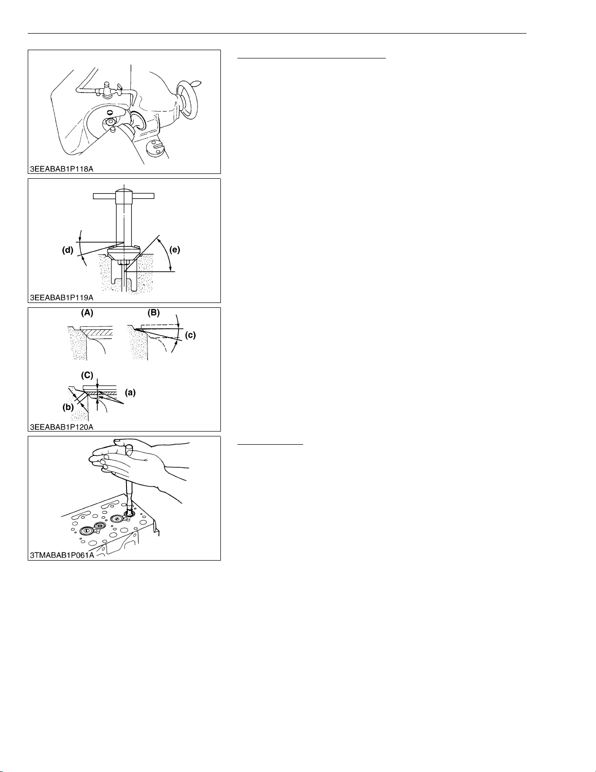
03-M-DI Series, WSM
KiSC issued 10, 2009 A
DIESEL ENGINE
Correcting Valve and Valve Seat
NOTEQ
• Before correcting the valve and seat, check the valve stem
and the I.D. of valve guide section, and repair them if
necessary.
• After correcting the valve seat, be sure to check the valve
recessing.
1) Correcting Valve
1. Correct the valve with a valve refacer.
2) Correcting Valve Seat
1. Slightly correct the seat surface with a 1.047 rad (60 °) (intake
valve) or 0.785 rad (45 °) (exhaust valve) seat cutter (Code No.
07909-33102).
2. Resurface the seat surface with a 0.523 rad (30 °) valve seat
cutter to intake valve seat and with a 0.262 rad (15 °) valve seat
cutter to exhaust valve seat so that the width is close to specified
valve seat width (2.12 mm, 0.0835 in.)
3. After resurfacing the seat, inspect for even valve seating, apply a
thin film of compound between the valve face and valve seat, and
fit them with valve lapping tool.
4. Check the valve seating with prussian blue. The valve seating
surface should show good contact all the way around.
(a) Identical Dimensions
(b) Valve Seat Width
(c) 0.523 rad (30 °) or 0.262 rad (15 °)
(d) 0.262 rad (15 °) or 0.523 rad (30 °)
(e) 0.785 rad (45 °) or 1.047 rad (60 °)
A: Check Correct
B: Correct Seat Width
C: Check Contact
W1028350
Valve Lapping
1. Apply compound evenly to the valve lapping surface.
2. Insert the valve into the valve guide. Lap the valve onto its seat
with a valve flapper or screwdriver.
3. After lapping the valve, wash the compound away and apply oil,
then repeat valve lapping with oil.
4. Apply prussian blue to the contact surface to check the seated
rate. If it is less than 70 %, repeat valve lapping again.
IMPORTANTQ
• When valve lapping is performed, be sure to check the valve
recessing and adjust the valve clearance after assembling
the valve.
W1028814
S-64
Page 86
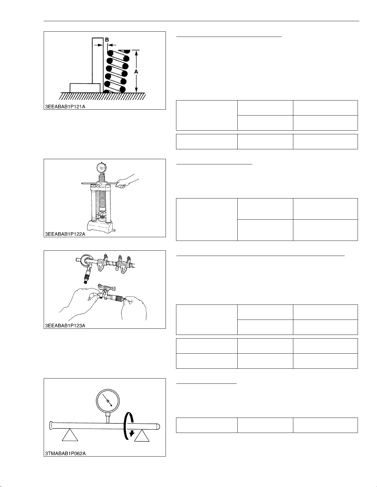
03-M-DI Series, WSM
KiSC issued 10, 2009 A
DIESEL ENGINE
Free Length and Tilt of Valve Spring
1. Measure the free length A of valve spring with vernier calipers. If
the measurement is less than the allowable limit, replace it.
2. Put the valve spring on a surface plate, place a square on the
side of the valve spring.
3. Check to see if the entire side is in contact with the square.
Rotate the valve spring and measure the maximum tilt B.
Check the entire surface of the valve spring for scratches.
If there is any defect, replace it.
Factory spec.
Free length A
Allowable limit
41.7 to 42.2 mm
1.6417 to 1.6614 in.
41.2 mm
1.6220 in.
Tilt B Allowable limit
1.0 mm
0.039 in.
W1028935
Valve Spring Setting Load
1. Place the valve spring on a tester and compress it to the same
length it is actually compressed in the engine.
2. Read the compression load on the gauge.
3. If the measurement is less than the allowable limit, replace it.
117.6 N / 35 mm
Factory spec.
Setting load /
Setting length
Allowable limit
12.0 kgf / 35 mm
26.4 lbs / 1.3780 in.
100.0 N / 35 mm
10.2 kgf / 35 mm
22.5 lbs / 1.3780 in.
W1078436
Oil Clearance between Rocker Arm and Rocker Arm Shaft
1. Measure the rocker arm shaft O.D. with an outside micrometer.
2. Measure the rocker arm I.D. with an inside micrometer, and then
calculate the oil clearance.
3. If the oil clearance exceeds the allowable limit, replace the rocker
arm and measure the oil clearance again. If it still exceeds the
allowable limit, replace also the rocker arm shaft.
Oil clearance between
rocker arm and rocker
arm shaft
Factory spec.
Allowable limit
0.016 to 0.045 mm
0.00063 to 0.00177 in.
0.10 mm
0.0039 in.
Rocker arm shaft O.D. Factory spec.
Rocker arm I.D. Factory spec.
13.973 to 13.984 mm
0.55012 to 0.55055 in.
14.000 to 14.018 mm
0.55118 to 0.55189 in.
W1029150
Push Rod Alignment
1. Place the push rod on V blocks.
2. Measure the push rod alignment.
3. If the measurement exceeds the allowable limit, replace the push
rod.
Push rod alignment Allowable limit
0.25 mm
0.0098 in.
W1029290
S-65
Page 87
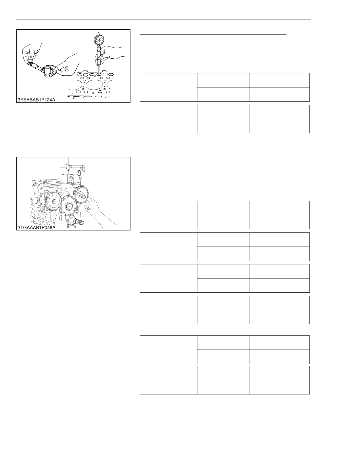
03-M-DI Series, WSM
KiSC issued 10, 2009 A
DIESEL ENGINE
Oil Clearance between Tappet and Tappet Guide Bore
1. Measure the tappet O.D. with an outside micrometer.
2. Measure the I.D. of the tappet guide bore with a cylinder gauge,
and calculate the oil clearance.
3. If the oil clearance exceeds the allowable limit or the tappet is
damaged, replace the tappet.
Oil Clearance between
tappet and tappet guide
bore
Factory spec.
Allowable limit
0.020 to 0.062 mm
0.00079 to 0.00244 in.
0.07 mm
0.0028 in.
Tappet O.D. Factory spec.
Tappet guide bore I.D. Factory spec.
(2) Timing Gears, Camshaft and Fuel Camshaft
Timing Gear Backlash
1. Set a dial indicator (lever type) with its tip on the gear tooth.
2. Move the gear to measure the backlash, holding its mating gear.
3. If the backlash exceeds the allowable limit, check the oil
clearance of the shafts and the gear.
4. If the oil clearance is proper, replace the gear.
Backlash between idle
gear and crank gear
Backlash between idle
gear and cam gear
Backlash between idle
gear and injection pump
gear
Factory spec.
Allowable limit
Factory spec.
Allowable limit
Factory spec.
Allowable limit
23.959 to 23.980 mm
0.94327 to 0.94410 in.
24.000 to 24.021 mm
0.94488 to 0.94571 in.
W1029366
0.0415 to 0.1122 mm
0.00163 to 0.00442 in.
0.15 mm
0.0059 in.
0.0415 to 0.1154 mm
0.00163 to 0.00454 in.
0.15 mm
0.0059 in.
0.0415 to 0.1154 mm
0.00163 to 0.00454 in.
0.15 mm
0.0059 in.
Backlash between crank
gear and oil pump gear
Factory spec.
Allowable limit
For Balancer Model Only
Backlash between idle
gear and balancer gear
(IN. side)
Backlash between cam
gear and balancer gear
(EX. side)
Factory spec.
Allowable limit
Factory spec.
Allowable limit
S-66
0.0415 to 0.1090 mm
0.00163 to 0.00429 in.
0.15 mm
0.0059 in.
0.0350 to 0.1160 mm
0.00138 to 0.00457 in.
0.15 mm
0.0059 in.
0.0350 to 0.1160 mm
0.00138 to 0.00457 in.
0.15 mm
0.0059 in.
W1029564
Page 88
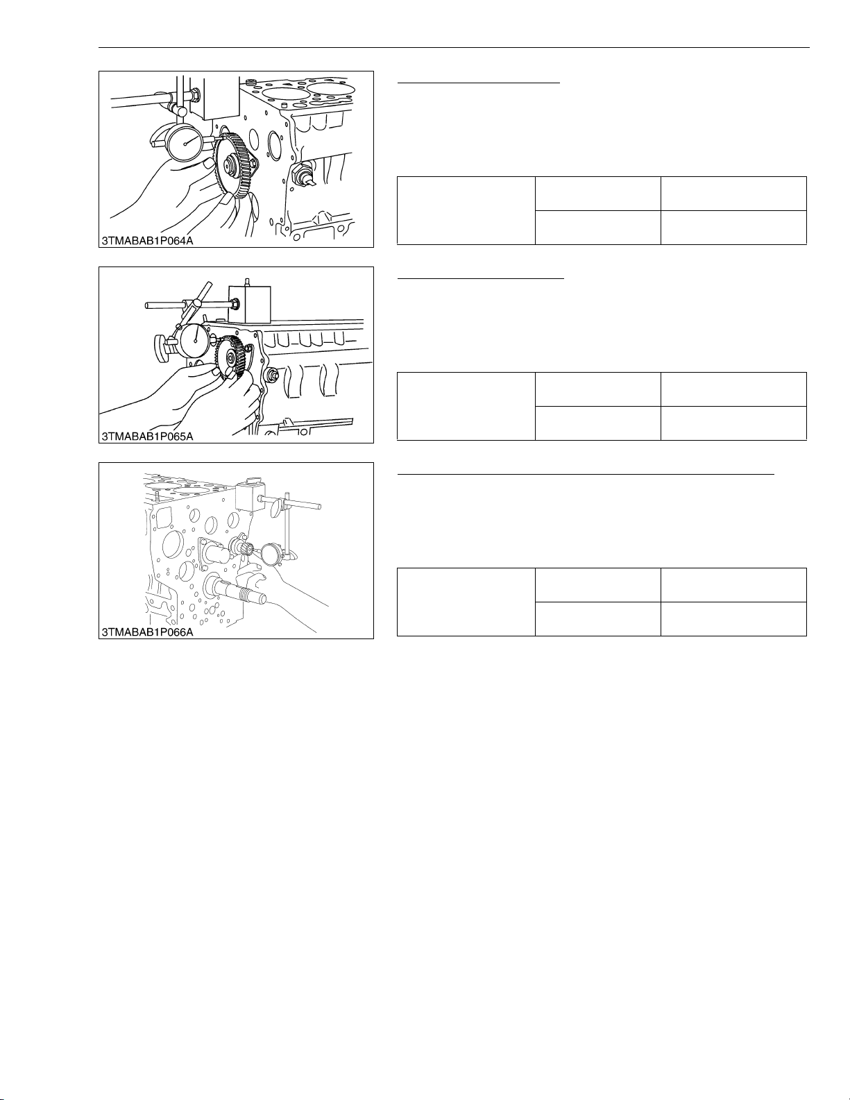
03-M-DI Series, WSM
KiSC issued 10, 2009 A
DIESEL ENGINE
Idle Gear Side Clearance
1. Set a dial indicator with its tip on the idle gear.
2. Measure the side clearance by moving the idle gear to the front
and rear.
3. If the measurement exceeds the allowable limit, replace the idle
gear collar.
Factory spec.
Idle gear side clearance
Allowable limit
0.12 to 0.48 mm
0.0047 to 0.0189 in.
0.9 mm
0.0354 in.
W1029843
Camshaft Side Clearance
1. Set a dial indicator with its tip on the camshaft.
2. Measure the side clearance by moving the cam gear to the front
and rear.
3. If the measurement exceeds the allowable limit, replace the
camshaft stopper.
0.07 to 0.22 mm
0.0028 to 0.0087 in.
0.30 mm
0.0118 in.
W1030012
Camshaft side
clearance
Factory spec.
Allowable limit
Balancer Shaft Side Clearance (For Balancer Model Only)
1. Set a dial indicator with tip on the balancer shaft.
2. Measure the side clearance by moving the balancer shaft to the
front and rear.
3. If the measurement exceeds the allowable limit, replace the
balancer shaft.
0.07 to 0.22 mm
0.0028 to 0.0087 in.
0.3 mm
0.0118 in.
W1030111
Side clearance of
balancer shaft
Factory spec.
Allowable limit
S-67
Page 89
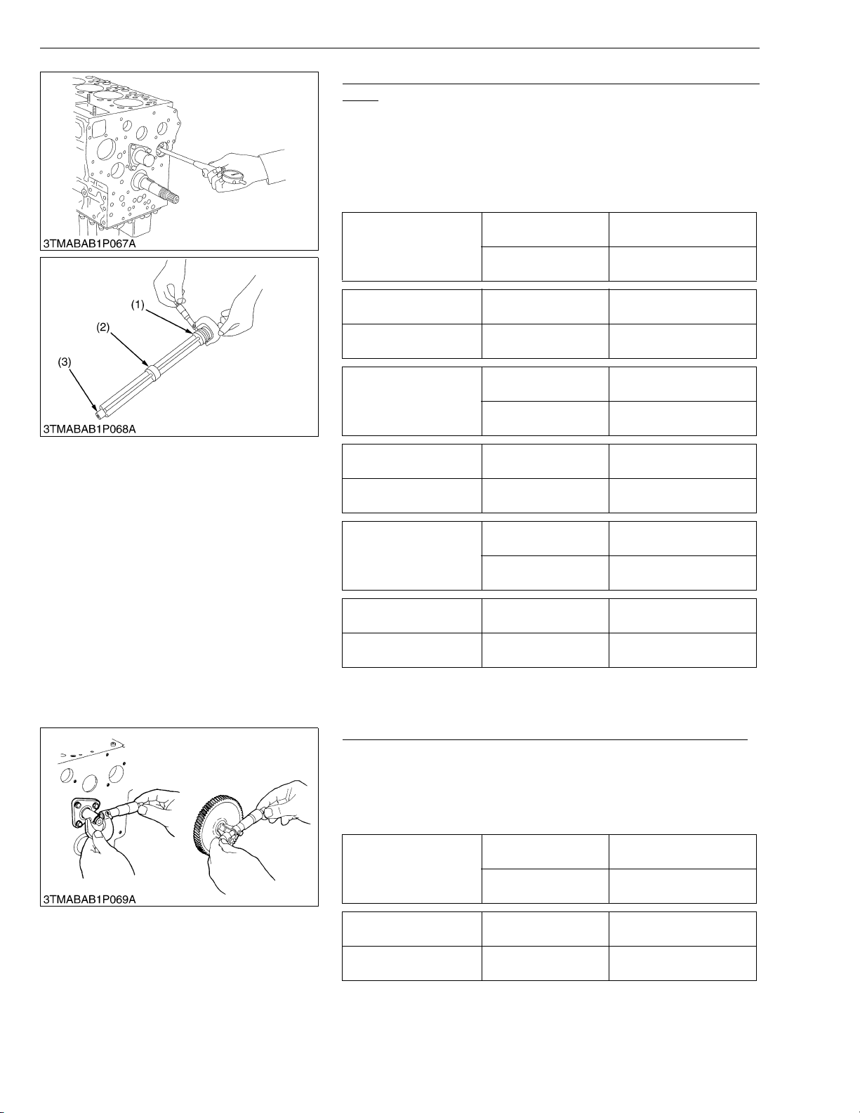
03-M-DI Series, WSM
KiSC issued 10, 2009 A
DIESEL ENGINE
Oil Clearance of Balancer Shaft Journal (For Balancer Model
Only)
1. Measure the balancer shaft journal O.D. with an outside
micrometer.
2. Measure the cylinder block bore I.D. for balancer shaft with an
inside micrometer or cylinder gauge.
3. If the clearance exceeds the allowable limit, replace the balancer
shaft.
0.030 to 0.111 mm
0.00118 to 0.00437 in.
0.2 mm
0.0079 in.
Oil clearance of
balancer shaft journal 1
Factory spec.
Allowable limit
Balancer shaft journal 1
O.D.
Balancer shaft bearing 1
I.D.
Oil clearance of
balancer shaft journal 2
Balancer shaft journal 2
O.D.
Balancer shaft bearing 2
I.D.
Oil clearance of
balancer shaft journal 3
Balancer shaft journal 3
O.D.
Balancer shaft bearing 3
I.D.
(1) Balancer Shaft Journal 1
(2) Balancer Shaft Journal 2
Factory spec.
Factory spec.
Factory spec.
Allowable limit
Factory spec.
Factory spec.
Factory spec.
Allowable limit
Factory spec.
Factory spec.
(3) Balancer Shaft Journal 3
43.934 to 43.950 mm
1.72968 to 1.73031 in.
43.980 to 44.045 mm
1.73149 to 1.73405 in.
0.030 to 0.111 mm
0.00118 to 0.00437 in.
0.2 mm
0.0079 in.
41.934 to 41.950 mm
1.65094 to 1.65157 in.
41.980 to 42.045 mm
1.65275 to 1.65531 in.
0.020 to 0.094 mm
0.00079 to 0.00370 in.
0.2 mm
0.0079 in.
21.947 to 21.960 mm
0.86405 to 0.86456 in.
21.980 to 22.041 mm
0.86535 to 0.86775 in.
W1030206
Oil Clearance between Idle Gear Shaft and Idle Gear Bushing
1. Measure the idle gear shaft O.D. with an outside micrometer.
2. Measure the idle gear bushing I.D. with an inside micrometer,
and calculate the oil clearance.
3. If the oil clearance exceeds the allowable limit, replace the
bushing.
Clearance between idle
gear shaft and idle gear
bushing
Factory spec.
Allowable limit
0.025 to 0.066 mm
0.00098 to 0.00260 in.
0.1 mm
0.0039 in.
Idle gear shaft O.D. Factory spec.
Idle gear bushing I.D. Factory spec.
S-68
37.959 to 37.975 mm
1.49445 to 1.49508 in.
38.000 to 38.025 mm
1.49606 to 1.49704 in.
W1030933
Page 90
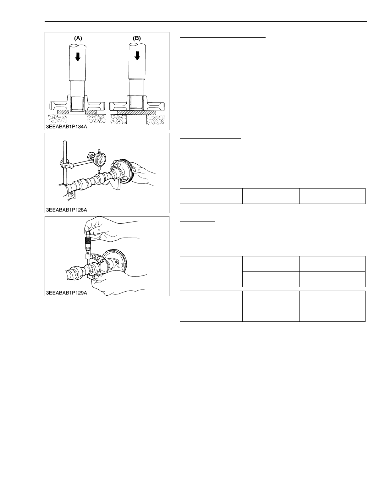
03-M-DI Series, WSM
KiSC issued 10, 2009 A
DIESEL ENGINE
Replacing Idle Gear Bushing
(A) (When removing)
1. Using an idle gear bushing replacing tool, press out the used
bushing.
(B) (When installing)
1. Clean a new idle gear bushing and idle gear bore, and apply
engine oil to them.
2. Using an idle gear bushing replacing tool, press in a new bushing
(service parts) to the specified dimension. (See figure.)
W1031083
Camshaft Alignment
1. Support the camshaft with V blocks on the surface plate at both
end journals.
2. Set a dial indicator with its tip on the intermediate journal.
3. Measure the camshaft alignment.
4. If the measurement exceeds the allowable limit, replace the
camshaft.
Camshaft alignment Allowable limit
0.01 mm
0.0004 in.
W1031413
Cam Height
1. Measure the height of the cam at its highest point with an outside
micrometer.
2. If the measurement is less than the allowable limit, replace the
camshaft.
Factory spec.
Cam height of intake
Allowable limit
Factory spec.
Cam height of exhaust
Allowable limit
33.90 mm
1.3346 in.
33.85 mm
1.3327 in.
33.90 mm
1.3346 in.
33.85 mm
1.3327 in.
W1031532
S-69
Page 91
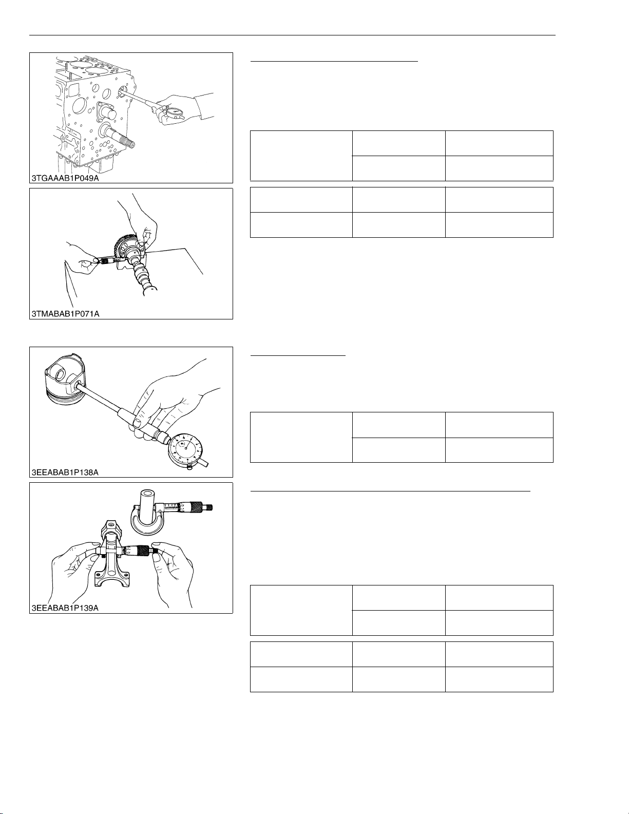
03-M-DI Series, WSM
KiSC issued 10, 2009 A
DIESEL ENGINE
Oil Clearance of Camshaft Journal
1. Measure the camshaft journal O.D. with an outside micrometer.
2. Measure the cylinder block bore I.D. for camshaft with a cylinder
gauge, and calculate the oil clearance.
3. If the oil clearance exceeds the allowable limit, replace the
camshaft.
0.050 to 0.091 mm
0.0020 to 0.0036 in.
0.15 mm
0.0059 in.
Oil clearance of
camshaft journal
Factory spec.
Allowable limit
(3) Piston and Connecting Rod
Camshaft journal O.D. Factory spec.
Cylinder block bore I.D. Factory spec.
39.934 to 39.950 mm
1.57221 to 1.57284 in.
40.000 to 40.025 mm
1.57480 to 1.57579 in.
W1031662
Piston Pin Bore I.D.
1. Measure the piston pin bore I.D. in both the horizontal and
vertical directions with a cylinder gauge.
2. If the measurement exceeds the allowable limit, replace the
piston.
Factory spec.
Piston pin bore I.D.
Allowable limit
25.000 to 25.013 mm
0.98425 to 0.98476 in.
25.05 mm
0.9862 in.
W1031817
Oil Clearance between Piston Pin and Small End Bushing
1. Measure the piston pin O.D. where it contacts the bushing with
an outside micrometer.
2. Measure the small end bushing I.D. with an inside micrometer,
and calculate the oil clearance.
3. If the oil clearance exceeds the allowable limit, replace the
bushing. If it still exceeds the allowable limit, replace the piston
pin.
Oil clearance between
piston pin and small end
bushing
Factory spec.
Allowable limit
0.014 to 0.038 mm
0.00055 to 0.00150 in.
0.15 mm
0.0059 in.
Piston pin O.D. Factory spec.
Small end bushing I.D. Factory spec.
S-70
25.002 to 25.011 mm
0.98433 to 0.98468 in.
25.025 to 25.040 mm
0.98523 to 0.98582 in.
W1031982
Page 92
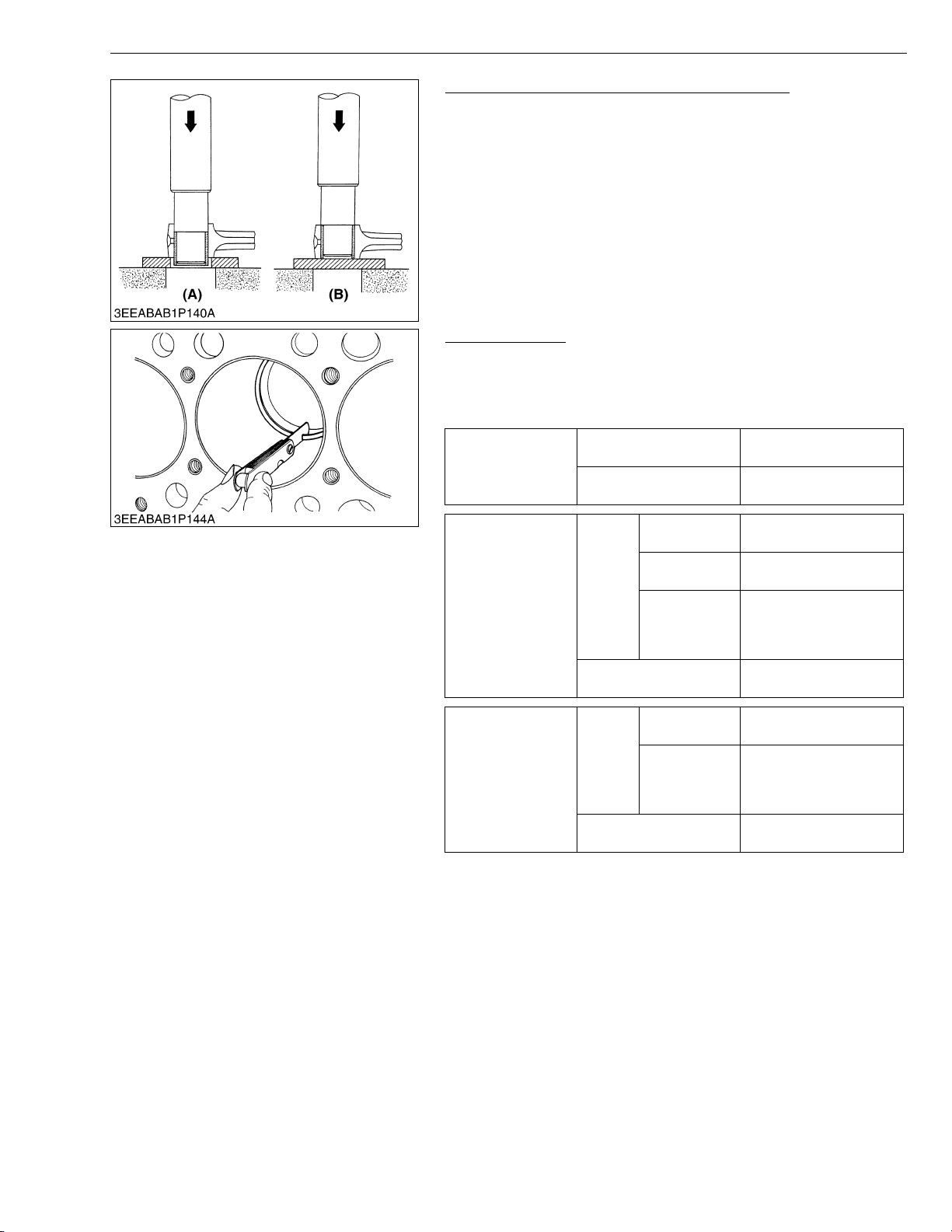
03-M-DI Series, WSM
KiSC issued 10, 2009 A
DIESEL ENGINE
Replacing Connecting Rod Small End Bushing
(A) (When removing)
1. Press out the small end bushing with a connecting rod small end
bushing replacing tool.
(B) (When installing)
1. Clean a new small end bushing and bore, and apply engine oil to
them.
2. Press fit a new bushing, taking due care to see that the
connecting rod hole matches the bushing hole.
W1032140
Piston Ring Gap
1. Insert the piston ring into the lower part of the liner (the least worn
out part) with the piston.
2. Measure the ring gap with a feeler gauge.
3. If the gap exceeds the allowable limit, replace the ring.
Factory spec.
Top ring
Allowable limit
0.20 to 0.35 mm
0.0079 to 0.0138 in.
1.25 mm
0.0492 in.
Second ring
Oil ring
D1503-M-DI
Factory
spec.
Allowable limit
Factory
spec.
Allowable limit
D1503-M-DI-T
D1703-M-DI
D1803-M-DI
V2203-M-DI
V2403-M-DI
D1503-M-DI
D1503-M-DI-T
D1703-M-DI
D1803-M-DI
V2203-M-DI
V2403-M-DI
0.30 to 0.45 mm
0.012 to 0.018 in.
0.40 to 0.55 mm
0.016 to 0.022 in.
0.35 to 0.50 mm
0.014 to 0.020 in.
1.25 mm
0.0492 in.
0.25 to 0.45 mm
0.0098 to 0.0177 in.
0.20 to 0.40 mm
0.0079 to 0.0157 in.
1.25 mm
0.0492 in.
W1032246
S-71
Page 93
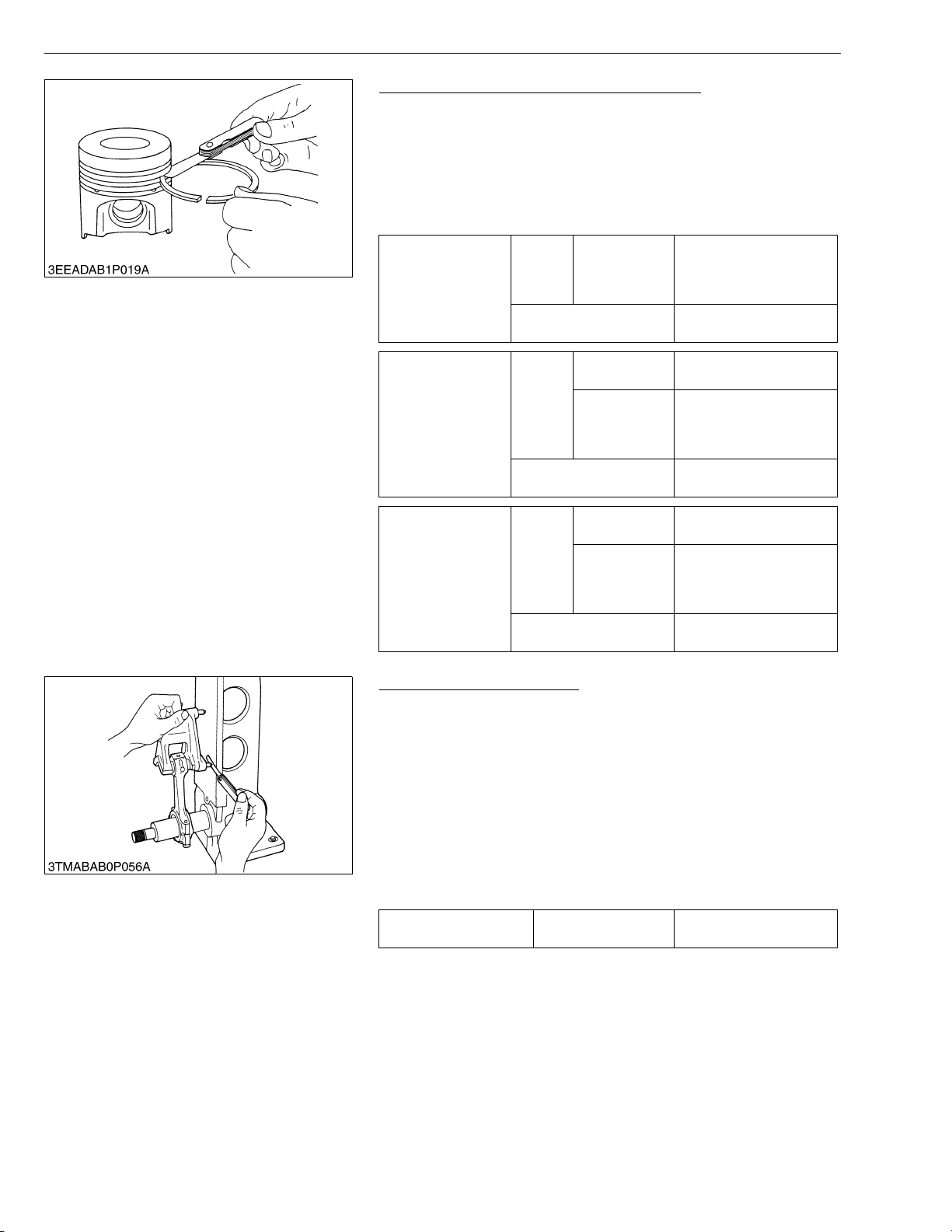
03-M-DI Series, WSM
KiSC issued 10, 2009 A
DIESEL ENGINE
Clearance between Piston Ring and Groove
1. Remove carbon from the ring grooves.
2. Measure the clearance between the ring and the groove with a
feeler gauge.
3. If the clearance exceeds allowable limit, replace the ring since
compression leak and oil shortage result.
4. if the clearance still exceeds the allowable limit after replacing the
ring, replace the piston.
D1703-M-DI
Top Ring
Factory
spec.
Allowable limit
D1803-M-DI
V2203-M-DI
V2403-M-DI
0.050 to 0.090 mm
0.0020 to 0.0035 in.
0.2 mm
0.0079 in.
Second ring
Oil ring
D1503-M-DI
D1503-M-DI-T
Factory
spec.
Allowable limit
Factory
spec.
Allowable limit
D1703-M-DI
D1803-M-DI
V2203-M-DI
V2403-M-DI
D1503-M-DI
D1503-M-DI-T
D1703-M-DI
D1803-M-DI
V2203-M-DI
V2403-M-DI
0.093 to 0.128 mm
0.0037 to 0.0050 in.
0.050 to 0.090 mm
0.0020 to 0.0035 in.
0.2 mm
0.0079 in.
0.020 to 0.060 mm
0.00079 to 0.00236 in.
0.030 to 0.070 mm
0.0012 to 0.0028 in.
0.15 mm
0.0059 in.
W1032489
Connecting Rod Alignment
NOTEQ
• Since the I.D. of the connecting rod small end bushing is the
basis of this check, check bushing for wear beforehand.
1. Install the piston pin into the connecting rod.
2. Install the connecting rod on the connecting rod alignment tool.
3. Put a gauge over the piston pin and move it against the face
plate.
4. If the gauge does not fit squarely against the face plate, measure
the space between the pin of the gauge and the face plate.
5. If the measurement exceeds the allowable limit, replace the
connecting rod.
Connecting rod
alignment
Allowable limit
0.05 mm
0.0020 in.
W1032720
S-72
Page 94
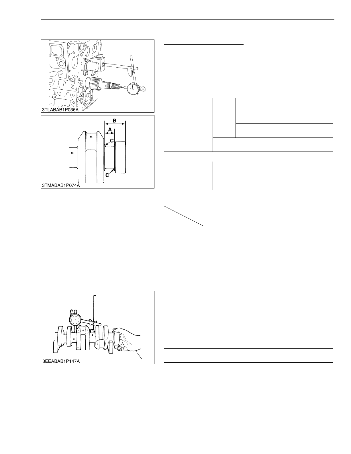
03-M-DI Series, WSM
KiSC issued 10, 2009 A
(4) Crankshaft
DIESEL ENGINE
Side Clearance of Crankshaft
1. Move the crankshaft to the flywheel side.
2. Set a dial indicator to the crankshaft.
3. Measure the end play by pulling the crankshaft toward the crank
gear.
4. If the measurement exceeds the allowable limit, replace the
thrust bearing 1 and 2.
(Serial No : below 3R9999)
D1503-M-DI
Crankshaft side
clearance
D1503-M-DI-T
Factory
spec.
Allowable limit
D1703-M-DI
V2203-M-DI
D1803-M-DI
V2403-M-DI
0.15 to 0.35 mm
0.0059 to 0.0138 in.
0.15 to 0.31 mm
0.0059 to 0.0122 in.
0.5 mm
0.0197 in.
(Serial No : above 3S0001)
0.15 to 0.31 mm
0.0059 to 0.0122 in.
0.5 mm
0.0197 in.
Crankshaft side
clearance
Factory spec.
Allowable limit
(Reference)
• Oversize dimensions of crankshaft journal
Oversize
Dimension
A
B
C
(0.4-S)
The crankshaft journal must be fine-finished to higher than ∇∇∇∇
0.2 mm
0.008 in.
26.20 to 26.25 mm
1.0315 to 1.0335 in.
54.5 to 54.7 mm
2.1456 to 2.1535 in.
2.8 to 3.2 mm radius
0.1102 to 0.1260 in. radius
0.4 mm
0.016 in.
26.40 to 26.45 mm
1.0394 to 1.0413 in.
54.6 to 54.8 mm
2.1496 to 2.1574 in.
2.8 to 3.2 mm radius
0.1102 to 0.1260 in. radius
W1032880
Crankshaft Alignment
1. Support the crankshaft with V blocks on the surface plate and set
a dial indicator with its tip on the intermediate journal at right
angle.
2. Rotate the crankshaft on the V blocks and get the misalignment
(half of the measurement).
3. If the misalignment exceeds the allowable limit, replace the
crankshaft.
Crankshaft alignment Allowable limit
0.02 mm
0.00079 in.
W1033001
S-73
Page 95
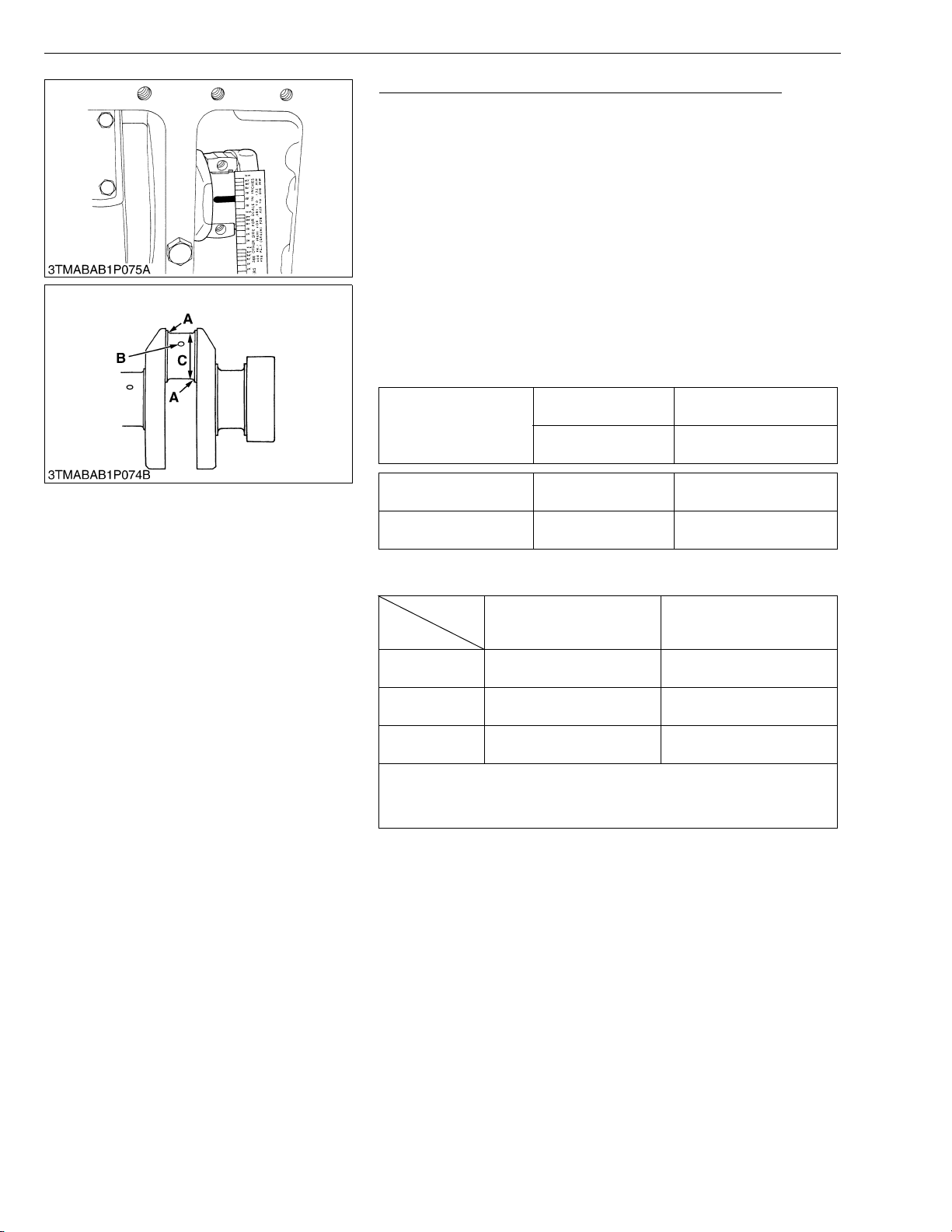
03-M-DI Series, WSM
KiSC issued 10, 2009 A
DIESEL ENGINE
Oil Clearance between Crankpin and Crankpin Bearing
1. Clean the crankpin and crankpin bearing.
2. Put a strip of plastigage (Code No.: 07909-30241) on the center
of the crankpin in each direction as shown in the figure.
3. Install the connecting rod cap and tighten the connecting rod
screws to the specified torque, and remove the cap again.
4. Measure the amount of the flattening with the scale, and get the
oil clearance.
5. If the oil clearance exceeds the allowable limit, replace the
crankpin bearing.
6. If the same size bearing is useless because of the crankpin wear,
replace it with an undersize one referring to the table and figure.
NOTEQ
• Never insert the plastigage into the crankpin oil hole.
• Be sure not to move the crankshaft while the connecting rod
screws are tightened.
Oil clearance between
crankpin and crankpin
bearing
Factory spec.
Allowable limit
0.025 to 0.087 mm
0.00098 to 0.00343 in.
0.2 mm
0.0079 in.
Crankpin O.D. Factory spec.
Crankpin bearing I.D. Factory spec.
46.959 to 46.975 mm
1.84878 to 1.84941 in.
47.000 to 47.046 mm
1.85039 to 1.85220 in.
(Reference)
• Undersize dimensions of crankpin
Undersize
Dimension
A
*B
C
(0.4S)
The crankpin must be fine-finished to higher than ∇∇∇∇
*Holes to be de-burred and edges rounded with 1.0 to 1.5 mm
(0.0394 to 0.0591 in.) relief.
0.2 mm
0.008 in.
3.3 to 3.7 mm radius
0.1299 to 0.1457 in. radius
1.0 to 1.5 mm relief
0.0394 to 0.0591 in. relief
46.759 to 46.775 mm
1.84091 to 1.84154 in.
0.4 mm
0.016 in.
3.3 to 3.7 mm radius
0.1299 to 0.1457 in. radius
1.0 to 1.5 mm relief
0.0394 to 0.0591 in. relief
46.559 to 46.575 mm
1.83303 to 1.83366 in.
W1033106
S-74
Page 96
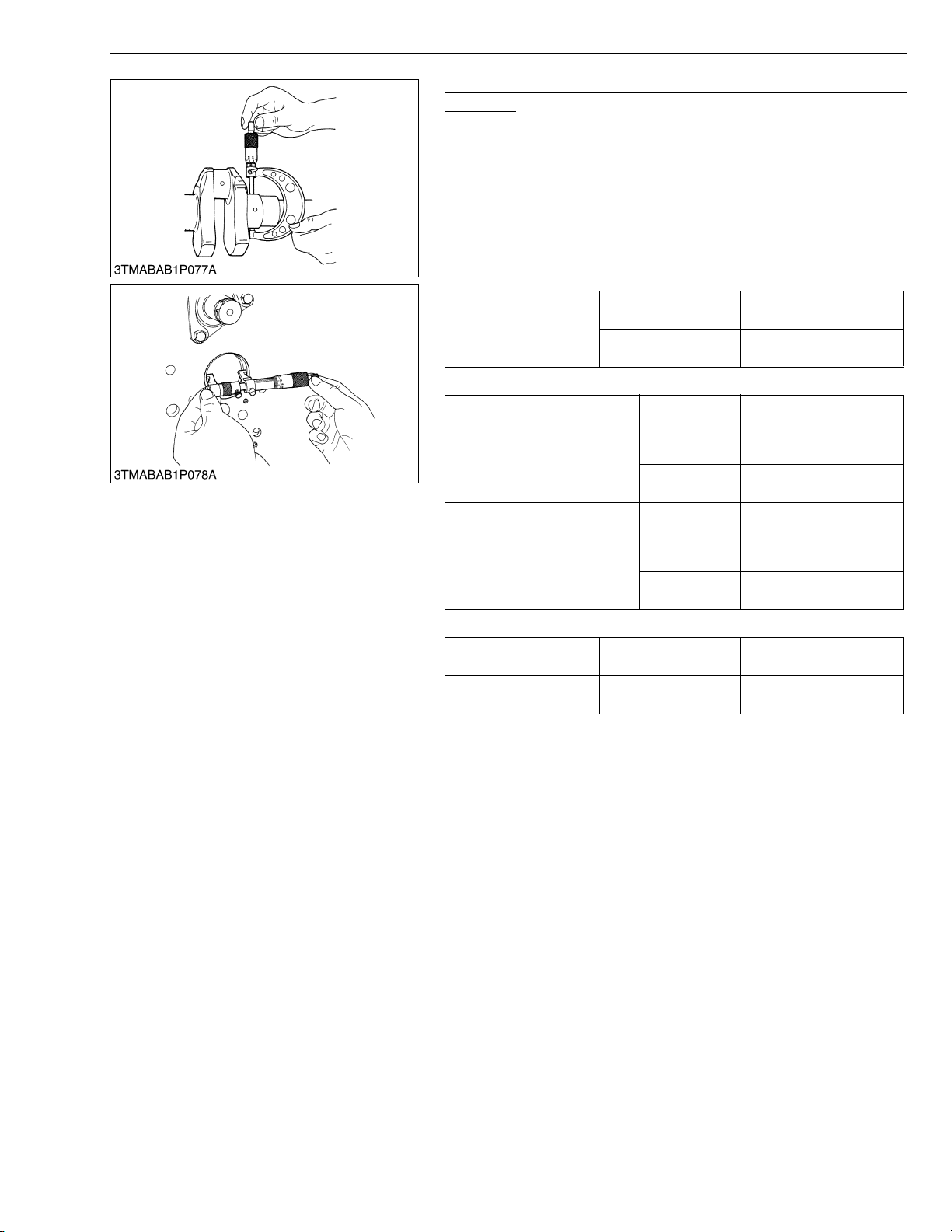
03-M-DI Series, WSM
KiSC issued 10, 2009 A
DIESEL ENGINE
Oil Clearance between Crankshaft Journal and Crankshaft
Bearing 1
1. Measure the O.D. of the crankshaft journal with an outside
micrometer.
2. Measure the I.D. of the crankshaft bearing 1 with an inside
micrometer, and calculate oil clearance.
3. If the clearance exceeds the allowable limit, replace the
crankshaft bearing 1.
4. If the same size bearing is useless because of the crankshaft
journal wear, replace it with an undersize one referring to the
table and figure.
Oil clearance between
crankshaft journal and
crankshaft bearing 1
Factory spec.
Allowable limit
0.040 to 0.118 mm
0.00157 to 0.00465 in.
0.2 mm
0.0079 in.
(Serial No. : below 3R9999)
D1503-M-DI
Crankshaft journal
O.D.
Crankshaft bearing
1 I.D.
Factory
spec.
Factory
spec.
D1503-M-DI-T
D1703-M-DI
V2203-M-DI
D1803-M-DI
V2403-M-DI
D1503-M-DI
D1503-M-DI-T
D1703-M-DI
V2203-M-DI
D1803-M-DI
V2403-M-DI
51.921 to 51.940 mm
2.04413 to 2.04488 in.
59.921 to 59.940 mm
2.35909 to 2.35984 in.
51.980 to 52.039 mm
2.04646 to 2.04878 in.
59.980 to 60.039 mm
2.36142 to 2.36374 in.
(Serial No. : above 3S0001)
Crankshaft journal O.D. Factory spec.
Crankshaft bearing 1
I.D.
Factory spec.
59.921 to 59.940 mm
2.35909 to 2.35984 in.
59.980 to 60.039 mm
2.36142 to 2.36374 in.
W1033717
S-75
Page 97
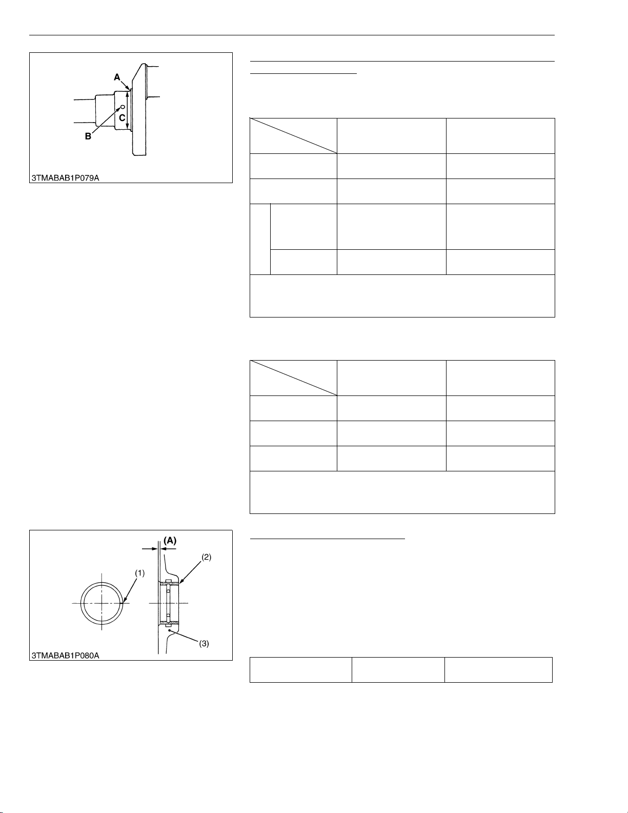
03-M-DI Series, WSM
KiSC issued 10, 2009 A
DIESEL ENGINE
Oil Clearance between Crankshaft Journal and Crankshaft
Bearing 1 (Continued)
(Serial No. : below 3R9999)
(Reference)
• Undersize dimensions of crankshaft journal
Undersize
Dimension
A
*B
D1503-M-DI
D1503-M-DI-T
D1703-M-DI
C
V2203-M-DI
D1803-M-DI
V2403-M-DI
(0.4S)
The crankpin must be fine-finished to higher than ∇∇∇∇
*Holes to be de-burred and edges rounded with 1.0 to 1.5 mm
(0.0394 to 0.0591 in.) relief.
0.2 mm
0.008 in.
2.8 to 3.2 mm radius
0.1102 to 0.1260 in. radius
1.0 to 1.5 mm relief
0.0394 to 0.0591 in. relief
51.721 to 51.740 mm
2.03626 to 2.03701 in.
59.721 to 59.740 mm
2.35122 to 2.35197 in.
0.4 mm
0.016 in.
2.8 to 3.2 mm radius
0.1102 to 0.1260 in. radius
1.0 to 1.5 mm relief
0.0394 to 0.0591 in. relief
51.521 to 51.540 mm
2.02839 to 2.02913 in.
59.521 to 59.540 mm
2.34335 to 2.34409 in.
(Serial No. : above 3S0001)
(Reference)
• Undersize dimensions of crankshaft journal
Undersize
Dimension
A
*B
C
(0.4S)
The crankpin must be fine-finished to higher than ∇∇∇∇
*Holes to be de-burred and edges rounded with 1.0 to 1.5 mm
(0.0394 to 0.0591 in.) relief.
0.2 mm
0.008 in.
2.8 to 3.2 mm radius
0.1102 to 0.1260 in. radius
1.0 to 1.5 mm relief
0.0394 to 0.0591 in. relief
59.721 to 59.740 mm
2.35122 to 2.35197 in.
0.4 mm
0.016 in.
2.8 to 3.2 mm radius
0.1102 to 0.1260 in. radius
1.0 to 1.5 mm relief
0.0394 to 0.0591 in. relief
59.521 to 59.540 mm
2.34335 to 2.34409 in.
W1073467
Replacing Crankshaft Bearing 1
(When removing)
1. Press out the used crankshaft bearing 1 (2) using a crankshaft
bearing 1 replacing tool.
(When installing)
1. Clean a new crankshaft bearing 1 (2) and crankshaft journal
bore, and apply engine oil to them.
2. Using a crankshaft bearing 1 replacing tool, press in a new
bearing 1 (2) so that its seam (1) directs toward the exhaust
manifold side.
Dimension (A) Factory spec.
4.2 to 4.5 mm
0.1654 to 0.1772 in.
(1) Seam
(2) Crankshaft Bearing 1
S-76
(3) Cylinder Block
(A) Dimension
W1033946
Page 98
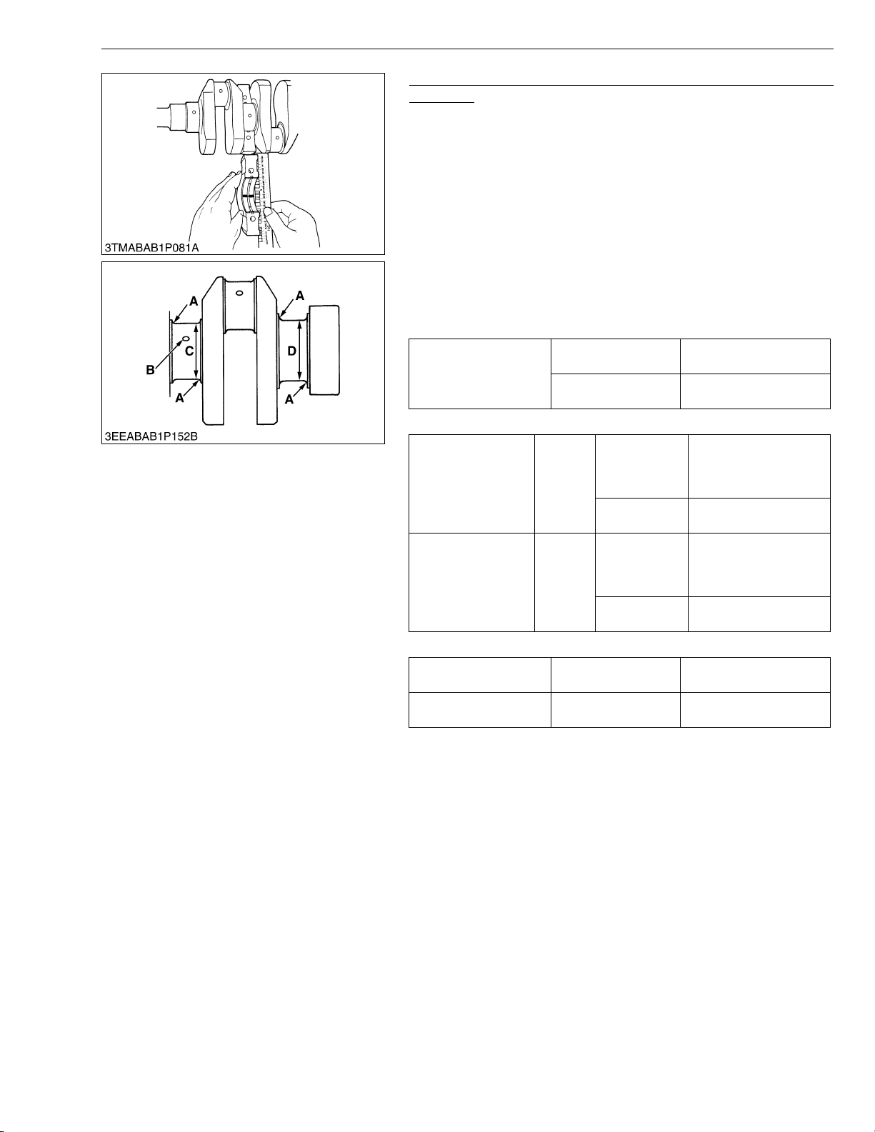
03-M-DI Series, WSM
KiSC issued 10, 2009 A
DIESEL ENGINE
Oil Clearance between Crankshaft Journal and Crankshaft
Bearing 2
1. Put a strip of plastigage on the center of the journal.
2. Install the bearing case and tighten the baring case screws 1 to
the specified torque, and remove the bearing case again.
3. Measure the amount of the flattening with the scale and get the
oil clearance.
4. If the clearance exceeds the allowable limit, replace the
crankshaft bearing 2.
5. If the same size bearing is useless because of the crankshaft
journal wear, replace it with an undersize one referring to the
table and figure.
NOTEQ
• Be sure not to move the crankshaft while the bearing case
screws are tightened.
Oil clearance between
crankshaft and
crankshaft bearing 2
Factory spec.
Allowable limit
0.040 to 0.104 mm
0.00157 to 0.00409 in.
0.20 mm
0.0079 in.
(Serial No. : below 3R9999)
D1503-M-DI
Crankshaft journal
O.D.
Crankshaft bearing 2
I.D.
Factory
spec.
Factory
spec.
D1503-M-DI-T
D1703-M-DI
V2203-M-DI
D1803-M-DI
V2403-M-DI
D1503-M-DI
D1503-M-DI-T
D1703-M-DI
V2203-M-DI
D1803-M-DI
V2403-M-DI
51.921 to 51.940 mm
2.04413 to 2.04488 in.
59.921 to 59.940 mm
2.35909 to 2.35984 in.
51.980 to 52.025 mm
2.04646 to 2.04823 in.
59.980 to 60.025 mm
2.36142 to 2.36318 in.
(Serial No. : above 3S0001)
Crankshaft journal O.D. Factory spec.
Crankshaft bearing 2
I.D.
Factory spec.
59.921 to 59.940 mm
2.35909 to 2.35984 in.
59.980 to 60.025 mm
2.36142 to 2.36318 in.
W1083821
S-77
Page 99
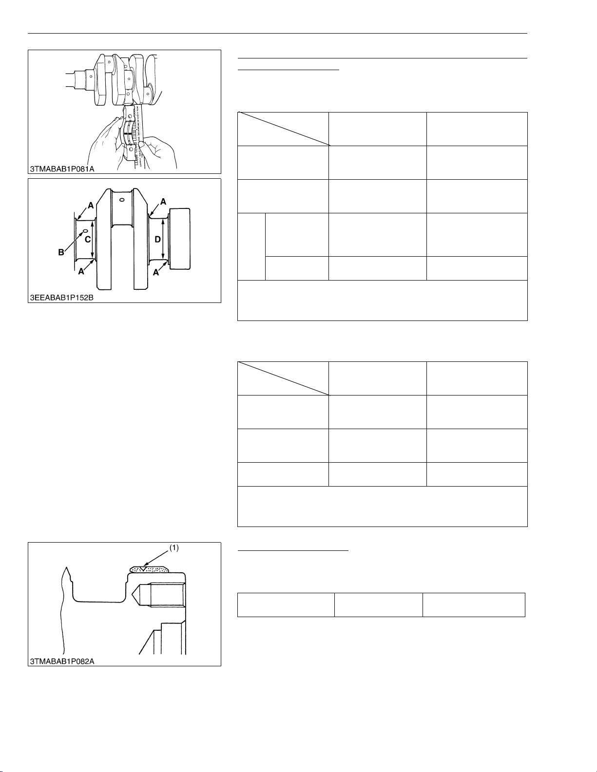
03-M-DI Series, WSM
KiSC issued 10, 2009 A
DIESEL ENGINE
Oil Clearance between Crankshaft Journal and Crankshaft
Bearing 2 (Continued)
(Serial No. : below 3R9999)
(Reference)
• Undersize dimensions of crankshaft journal
Undersize
Dimension
A
*B
D1503-M-DI
D1503-M-DI-T
D1703-M-DI
C, D
V2203-M-DI
D1803-M-DI
V2403-M-DI
(0.4S)
The crankpin must be fine-finished to higher than ∇∇∇∇
*Holes to be de-burred and edges rounded with 1.0 to 1.5 mm
(0.0394 to 0.0591 in.) relief.
0.2 mm
0.008 in.
2.8 to 3.2 mm radius
0.1102 to 0.1260 in.
radius
1.0 to 1.5 mm relief
0.0394 to 0.0591 in.
relief
51.721 to 51.740 mm
2.03626 to 2.03701 in.
59.721 to 59.740 mm
2.35122 to 2.35197 in.
0.4 mm
0.016 in.
2.8 to 3.2 mm radius
0.1102 to 0.1260 in.
radius
1.0 to 1.5 mm relief
0.0394 to 0.0591 in. relief
51.521 to 51.540 mm
2.02839 to 2.02913 in.
59.521 to 59.540 mm
2.34335 to 2.34409 in.
(Serial No. : above 3S0001)
(Reference)
• Undersize dimensions of crankshaft journal
Undersize
Dimension
A
*B
C, D
(0.4S)
The crankpin must be fine-finished to higher than ∇∇∇∇
*Holes to be de-burred and edges rounded with 1.0 to 1.5 mm
(0.0394 to 0.0591 in.) relief.
0.2 mm
0.008 in.
2.8 to 3.2 mm radius
0.1102 to 0.1260 in.
radius
1.0 to 1.5 mm relief
0.0394 to 0.0591 in.
relief
59.721 to 59.740 mm
2.35122 to 2.35197 in.
0.4 mm
0.016 in.
2.8 to 3.2 mm radius
0.1102 to 0.1260 in.
radius
1.0 to 1.5 mm relief
0.0394 to 0.0591 in. relief
59.521 to 59.540 mm
2.34335 to 2.34409 in.
W1034075
Crankshaft Sleeve Wear
1. Check the wear on the crankshaft sleeve (1).
2. If the wear exceeds the allowable limit or when the engine oil
leaks, replace the crankshaft sleeve (1).
Wear of sleeve Allowable limit
0.1 mm
0.0039 in.
(1) Crankshaft Sleeve
W1033354
S-78
Page 100
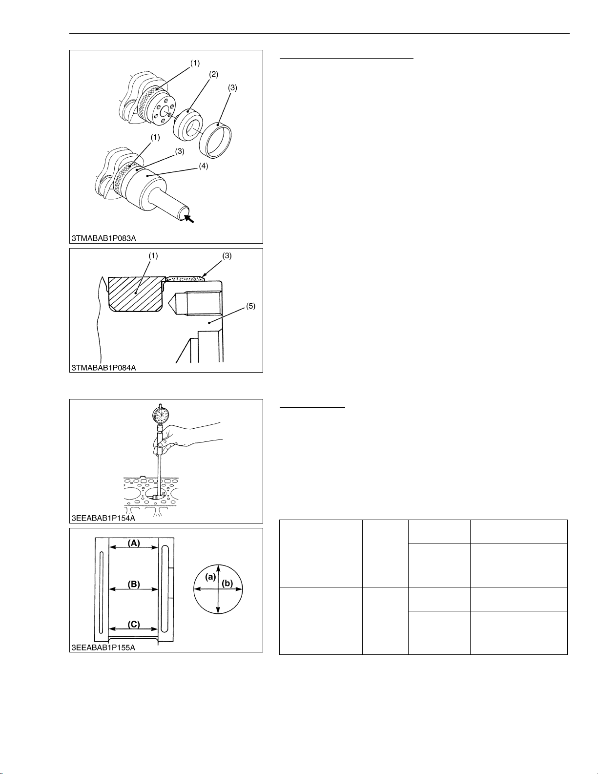
03-M-DI Series, WSM
KiSC issued 10, 2009 A
DIESEL ENGINE
Replacing Crankshaft Sleeve
1. Remove the used crankshaft sleeve (3) using a special-use puller
set (Code No.: 07916-32091).
2. Set the sleeve guide (2) to the crankshaft (5).
3. Set the stopper (1) to the crankshaft (5) as shown in figure.
4. Heat a new sleeve to a temperature between 150 and 200 °C
(302 to 392 °F), and fix the sleeve to the crankshaft (5) as shown
in figure.
5. Press fit the sleeve using the auxiliary socket for pushing (4).
NOTEQ
• Mount the sleeve with its largely chamfered surface facing
outward.
(1) Stopper
(2) Sleeve Guide
(3) Crankshaft Sleeve
(4) Auxiliary Socket for Pushing
(5) Crankshaft
W1033503
(5) Cylinder
Cylinder Wear
1. Measure the I.D. of the cylinder at the six positions (see figure)
with a cylinder gauge to find the maximum and minimum I.D.’s.
2. Get the difference (Maximum wear) between the maximum and
the minimum I.D.’s.
3. If the wear exceeds the allowable limit, bore and hone to the
oversize dimension. (Refer to “Correcting Cylinder”.)
4. Visually check the cylinder wall for scratches. If deep scratches
are found, the cylinder should be bores. (Refer to “Correcting
Cylinder”.)
Cylinder I.D.
Maximum wear
A: Top
B: Middle
C: Bottom (Skirt)
Factory
spec.
Allowable
limit
D1503-M-DI
D1503-M-DI-T
D1703-M-DI
D1803-M-DI
V2203-M-DI
V2403-M-DI
D1503-M-DI
D1503-M-DI-T
D1703-M-DI
D1803-M-DI
V2203-M-DI
V2403-M-DI
(a) Right-angled to Piston Pin
(b) Piston Pin Direction
83.000 to 83.022 mm
3.26772 to 3.26858 in.
87.000 to 87.022 mm
3.42519 to 3.42606 in.
83.150 mm
3.2736 in.
87.150 mm
3.4311 in.
W1034389
S-79
 Loading...