

Page 1
ENGLISH
1J412-8911-1
MODELS
Z482-E3 · Z602-E3
D722-E3 · D782-E3 · D902-E3
D1005-E3 · D1105-E3
D1105-TE3 · D1305-E3
V1505-E3 · V1505-TE3 · D1005-E3BG
D1105-E3BG · V1505-E3BG
D1503-M-E3 · D1703-M-E3 · D1803-M-E3
V2003-M-E3 · V2203-M-E3 · V2403-M-E3 · V2403-M-T-E3
D1803-M-DI-E3 · V2403-M-DI-E3
V3600-E3 · V3600-T-E3 · V3300-E3BG · V3600-T-E3BG
1ABABAAAP15001ABAAAAAP1560
B-1554D-2357
Page 2

ENGLISH
FOREWORD
SAFETY FIRST
FOREWORD
You are now the proud owner of a KUBOTA Engine. This engine is a
product of KUBOTA quality engineering and manufacturing. It is made
of fi ne materials and under a rigid quality control system. It will give you
long, satisfactory service. To obtain the best use of your engine, please
read this manual carefully. It will help you become familiar with the
operation of the engine and contains many helpful hints about engine
maintenance. It is KUBOTA's policy to utilize as quickly as possible every
advance in our research. The immediate use of new techniques in the
manufacture of products may cause some small parts of this manual to be
outdated. KUBOTA distributors and dealers will have the most up-to-date
information. Please do not hesitate to consult with them.
SAFETY FIRST
3
This symbol, the industry's "Safety Alert Symbol", is used throughout this
manual and on labels on the machine itself to warn of the possibility of
personal injury. Read these instructions carefully. It is essential that you
read the instructions and safety regulations before you attempt to assemble
or use this unit.
DANGER : Indicates an imminently hazardous situation which, if
3
not avoided, will result in death or serious injury.
WARNING : Indicates a potentially hazardous situation which, if not
3
CAUTION : Indicates a potentially hazardous situation which, if not
3
IMPORTANT : Indicates that equipment or property damage could
NOTE : Gives helpful information.
avoided, COULD result in death or serious injury.
avoided, MAY result in minor or moderate injury.
result if instructions are not followed.
Page 3

CONTENTS
SAFE OPERATION ............................................................................................. 1
SERVICING OF THE ENGINE ................................................................................. 1
NAMES OF PARTS .................................................................................................. 2
PRE-OPERATION CHECK....................................................................................... 4
BREAK-IN ............................................................................................................. 4
DAILY CHECK ...................................................................................................... 4
OPERATING THE ENGINE ...................................................................................... 5
STARTING THE ENGINE (NORMAL) .................................................................. 5
COLD WEATHER STARTING .............................................................................. 7
STOPPING THE ENGINE ..................................................................................... 7
CHECKS DURING OPERATION .......................................................................... 8
Radiator cooling water (Coolant) ........................................................................................ 8
Oil pressure lamp................................................................................................................ 9
Fuel..................................................................................................................................... 9
Color of exhaust.................................................................................................................. 9
Immediately stop the engine if;........................................................................................... 9
REVERSED ENGINE REVOLUTION AND REMEDIES ....................................... 9
How to tell when the engine starts running backwards....................................................... 9
Remedies............................................................................................................................ 9
MAINTENANCE...................................................................................................... 10
SERVICE INTERVALS........................................................................................ 11
PERIODIC SERVICE .............................................................................................. 18
FUEL ................................................................................................................... 18
Fuel level check and refueling .......................................................................................... 18
Air bleeding the fuel system.............................................................................................. 19
Checking the fuel pipes .................................................................................................... 21
Cleaning the fuel filter pot................................................................................................. 22
Fuel filter cartridge replacement ....................................................................................... 23
ENGINE OIL........................................................................................................ 23
Checking oil level and adding engine oil........................................................................... 23
Changing engine oil.......................................................................................................... 25
Replacing the oil filter cartridge ........................................................................................ 26
RADIATOR.......................................................................................................... 27
Checking coolant level, adding coolant ............................................................................ 27
Changing coolant.............................................................................................................. 29
Remedies for quick decrease of coolant........................................................................... 30
Checking radiator hoses and clamp ................................................................................. 30
Precaution at overheating................................................................................................. 30
Cleaning radiator core (outside) ....................................................................................... 30
Anti-freeze ........................................................................................................................ 31
AIR CLEANER .................................................................................................... 32
Evacuator valve ................................................................................................................ 32
Dust indicator (optional).................................................................................................... 32
ENGLISH
Page 4

CONTENTS
Evacuator valve ................................................................................................................ 33
Dust indicator (optional).................................................................................................... 33
Cleaning primary air filter element.................................................................................... 34
Evacuator valve ................................................................................................................ 34
For the air cleaner with a dust cup (optional).................................................................... 34
Dust indicator (optional).................................................................................................... 35
BATTERY............................................................................................................ 35
Battery charging................................................................................................................ 35
Direction for long term storage ......................................................................................... 36
ELECTRIC WIRING ............................................................................................ 37
FAN BELT ........................................................................................................... 37
Adjusting fan belt tension.................................................................................................. 37
CARRIAGE AND STORAGE .................................................................................. 38
ENGLISH
CARRIAGE.......................................................................................................... 38
STORAGE........................................................................................................... 38
TROUBLESHOOTING............................................................................................ 39
SPECIFICATIONS .................................................................................................. 41
WIRING DIAGRAMS .............................................................................................. 56
Page 5
SAFE OPERATION
Careful operation is your best assurance against an accident. Read and understand this
section carefully before operating the engine. All operators, no matter how much
experience they may have, should read this and other related manuals before operating
the engine or any equipment attached to it. It is the owner's obligation to provide all
operators with this information and instruct them on safe operation.
Be sure to observe the following for safe operation.
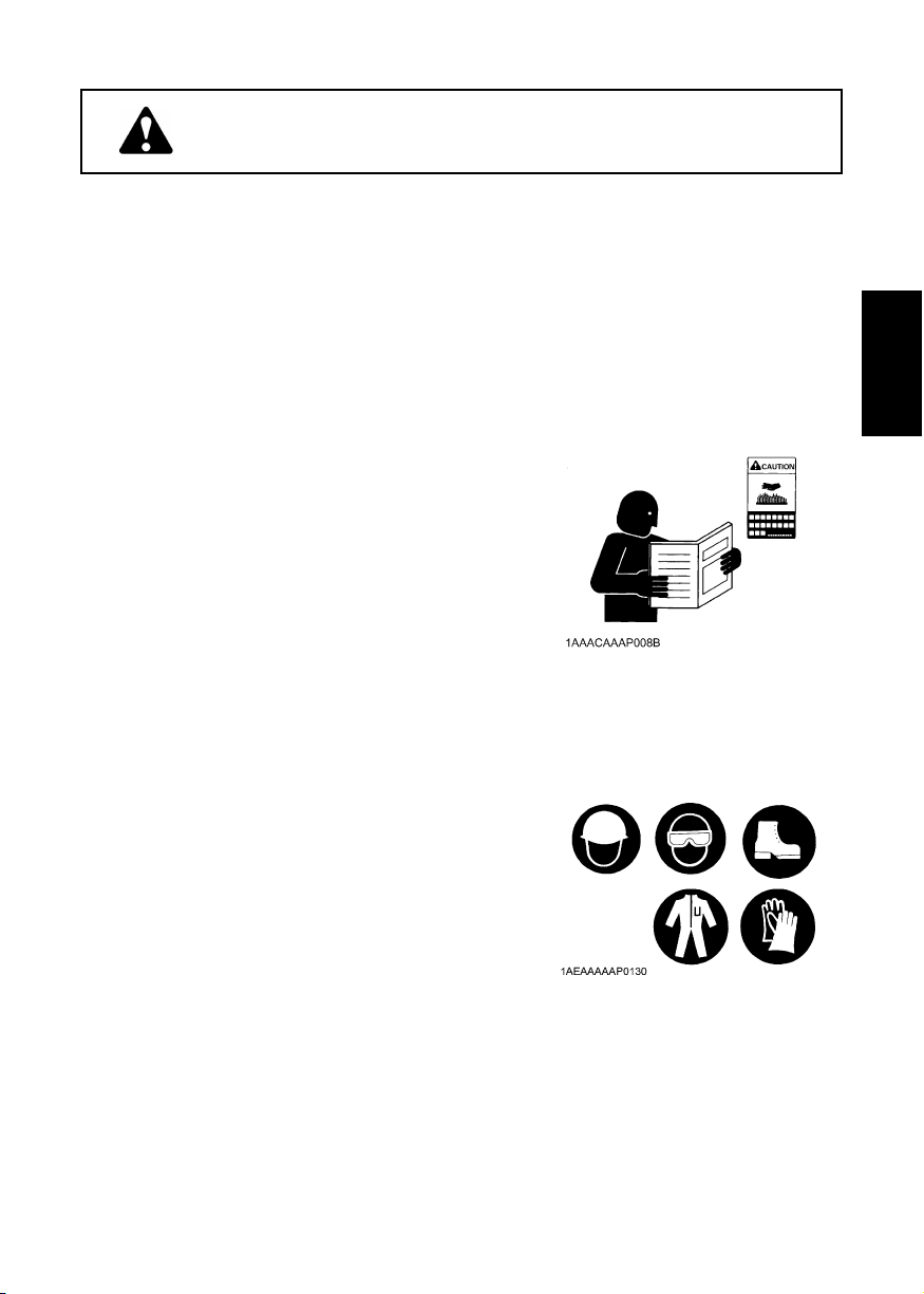
1. OBSERVE SAFETY INSTRUCTIONS
A Read and understand carefully this "OPERATOR'S
MANUAL" and "LABELS ON THE ENGINE" before
attempting to start and operate the engine.
A Learn how to operate and work safely. Know your
equipment and its limitations. Always keep the engine in
good condition.
A Before allowing other people to use your engine, explain
how to operate and have them read this manual before
operation.
A DO NOT modify the engine. UNAUTHORIZED
MODIFICATIONS to the engine may impair the function
and/or safety and affect engine life. If the engine does
not perform properly, consult your local Kubota Engine
Distributor first.
1SAFE OPERATION
ENGLISH
2. WEAR SAFE CLOTHING AND PERSONAL PROTECTIVE EQUIPMENT (PPE)
A DO NOT wear loose, torn or bulky clothing around the
machine that may catch on working controls and
projections or into fans, pulleys and other moving parts
causing personal injury.
A Use additional safety items-PPE, e.g. hard hat, safety
protection, safety goggles, gloves, etc., as appropriate
or required.
A DO NOT operate the machine or any equipment
attached to it while under the influence of alcohol,
medication, or other drugs, or while fatigued.
A DO NOT wear radio or music headphones while
operating the engine.
Page 6
2 SAFE OPERATION
3. CHECK BEFORE STARTING & OPERATING THE ENGINE
A Be sure to inspect the engine before operation. Do not
operate the engine if there is something wrong with it.
Repair it immediately.
A Ensure all guards and shields are in place before operating
the engine. Replace any that are damaged or missing.
A Check to see that you and others are a safe distance
from the engine before starting.
A Always keep the engine at least 3 feet (1 meter) away
from buildings and other facilities.
A DO NOT allow children or livestock to approach the
machine while the engine is running.
A DO NOT start the engine by shorting across starter
ENGLISH
terminals. The machine may start in gear and move. Do
not bypass or defeat any safety devices.
4. KEEP THE ENGINE AND SURROUNDINGS CLEAN
A Be sure to stop the engine before cleaning.
A Keep the engine clean and free of accumulated dirt, grease
and trash to avoid a fire. Store flammable fluids in proper
containers and cabinets away from sparks and heat.
A Check for and repair leaks immediately.
A DO NOT stop the engine without idling; Allow the engine
to cool down, first. Keep the engine idling for about 5
minutes before stopping unless there is a safety
problem that requires immediate shut down.
5.
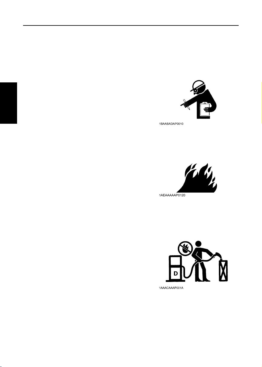
SAFE HANDLING OF FUEL AND LUBRICANTS -KEEP AWAY FROM FIRE
A Always stop the engine before refueling and/or
lubricating.
A DO NOT smoke or allow flames or sparks in your work
area. Fuel is extremely flammable and explosive under
certain conditions.
A Refuel at a well ventilated and open place. When fuel
and/or lubricants are spilled, refuel after letting the
engine cool down.
A DO NOT mix gasoline or alcohol with diesel fuel. The
mixture can cause a fire or severe engine damage.
A Do not use unapproved containers e.g. buckets, bottles,
jars. Use approved fuel storage containers and
dispensers.
Page 7
6. EXHAUST GASES & FIRE PREVENTION
A Engine exhaust fumes can be very harmful if allowed to
accumulate. Be sure to run the engine in a well
ventilated location and where there are no people or
livestock near the engine.
A The exhaust gas from the muffler is very hot. To prevent
a fire, do not expose dry grass, mowed grass, oil or any
other combustible materials to exhaust gas. Keep the
engine and muffler clean at all times.
A To avoid a fire, be alert for leaks of flammable
substances from hoses and lines. Be sure to check for
leaks from hoses or pipes, such as fuel and hydraulic
fluid by following the maintenance check list.
A To avoid a fire, do not short across power cables and
wires. Check to see that all power cables and wirings
are in good condition. Keep all electrical connections
clean. Bare wire or frayed insulation can cause a
dangerous electrical shock and personal injury.
7. ESCAPING FLUID
A Relieve all pressure in the air, the oil and the cooling
systems before disconnecting any lines, fittings or
related items.
A Be cautious of possible pressure relief when
disconnecting any device from a pressurized system
that utilizes pressure. DO NOT check for pressure leaks
with your hand. High pressure oil or fuel can cause
personal injury.
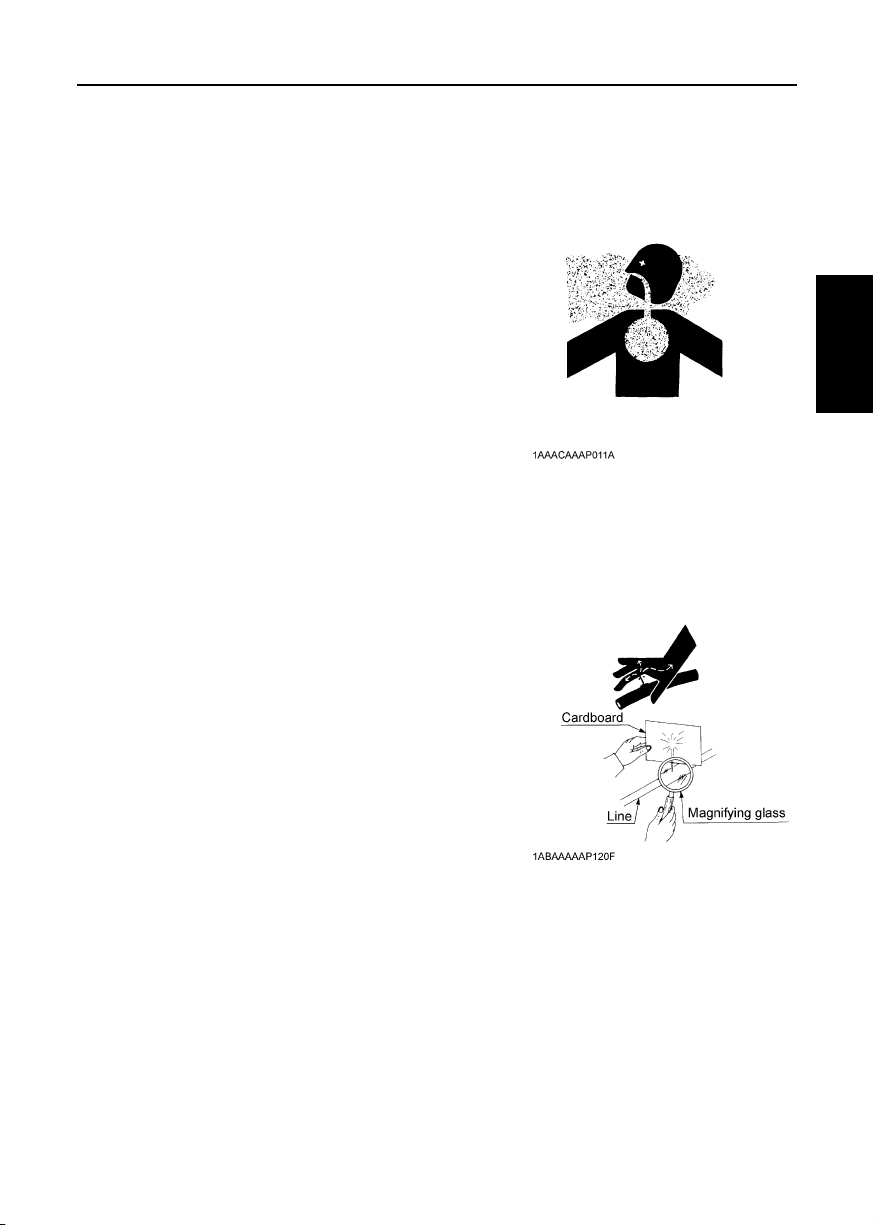
A Escaping fluid under pressure has sufficient force to
penetrate skin causing serious personal injury.
A Fluid escaping from pinholes may be invisible. Use a
piece of cardboard or wood to search for suspected
leaks: do not use hands and body. Use safety goggles
or other eye protection when checking for leaks.
A If injured by escaping fluid, see a medical doctor
immediately. This fluid can produce gangrene or severe
allergic reaction.
3SAFE OPERATION
ENGLISH
Page 8
4 SAFE OPERATION
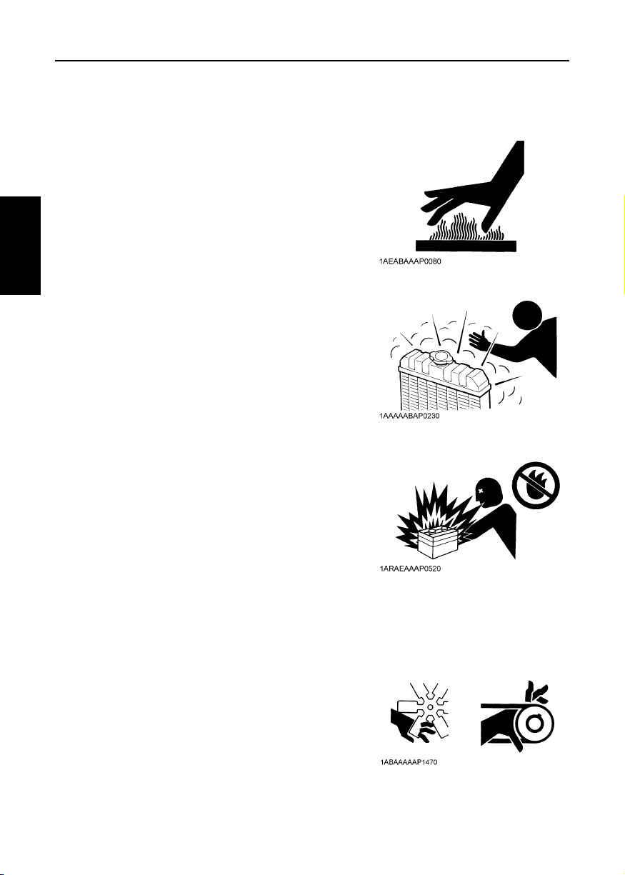
8. CAUTIONS AGAINST BURNS & BATTERY EXPLOSION
A To avoid burns, be cautious of hot components, e.g.
muffler, muffler cover, radiator, hoses, engine body,
coolants, engine oil, etc. during operation and after the
engine has been shut off.
A DO NOT remove the radiator cap while the engine is
running or immediately after stopping. Otherwise hot
water will spout out from the radiator. Wait until the
radiator is completely cool to the touch before removing
the cap. Wear safety goggles.
A Be sure to close the coolant drain valve, secure the
pressure cap, and fasten the pipe band before
operating. If these parts are taken off, or loosened, it will
ENGLISH
result in serious personal injury.
A The battery presents an explosive hazard. When the
battery is being charged, hydrogen and oxygen gases
are extremely explosive.
A DO NOT use or charge the battery if its fluid level is
below the LOWER mark.
Otherwise, the component parts may deteriorate earlier
than expected, which may shorten the service life or
cause an explosion. Immediately, add distilled water
until the fluid level is between the UPPER and LOWER
marks.
A Keep sparks and open flames away from the battery,
especially during charging. DO NOT strike a match near
the battery.
A DO NOT check the battery charge by placing a metal
object across the terminals. Use a voltmeter or
hydrometer.
A DO NOT charge a frozen battery. There is a risk of
explosion. When frozen, warm the battery up to at least
16°C (61°F).
9. KEEP HANDS AND BODY AWAY FROM ROTATING PARTS
A Be sure to stop the engine before checking or adjusting
the belt tension and cooling fan.
A Keep your hands and body away from rotating parts,
such as the cooling fan, V-belt, fan drive pulley or
flywheel. Contact with rotating parts can cause severe
personal injury.
A DO NOT run the engine without safety guards. Install
safety guards securely before operation.
Page 9
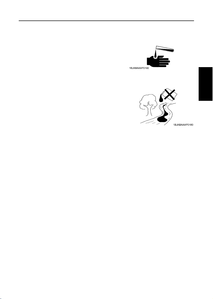
10. ANTI-FREEZE & DISPOSAL OF FLUIDS
A Anti-freeze contains poison. Wear rubber gloves to
avoid personal injury. In case of contact with skin, wash
it off immediately.
A DO NOT mix different types of Anti-freeze. The mixture
can produce a chemical reaction causing harmful
substances. Use approved or genuine KUBOTA Antifreeze.
A Be mindful of the environment and the ecology. Before
draining any fluids, determine the correct way to dispose
of them. Observe the relevant environmental protection
regulations when disposing of oil, fuel, coolant, brake
fluid, filters and batteries.
A When draining fluids from the engine, place a suitable
container underneath the engine body.
A DO NOT pour waste onto the ground, down a drain, or
into any water source. Dispose of waste fluids according
to environmental regulations.
5SAFE OPERATION
ENGLISH
Page 10
6 SAFE OPERATION
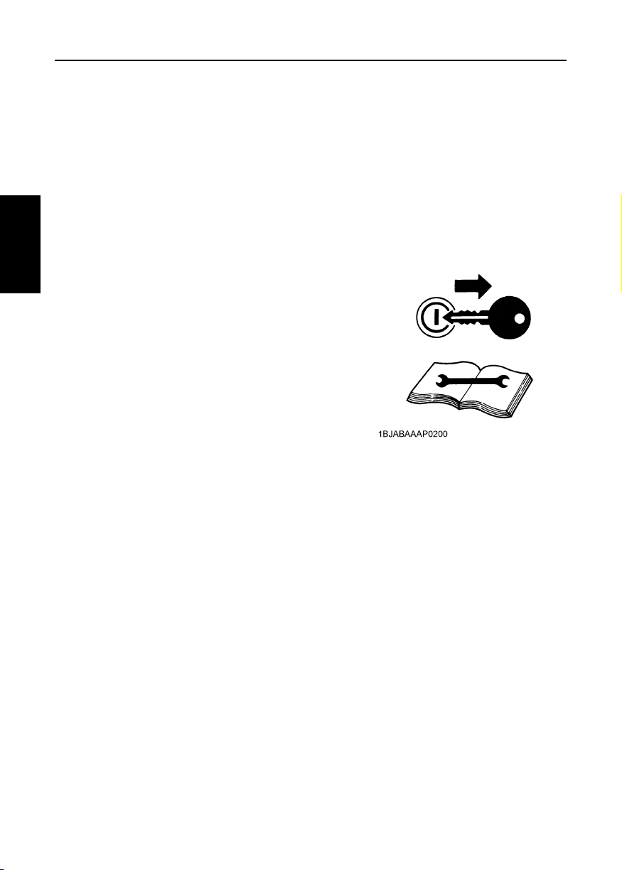
11. CONDUCTING SAFETY CHECKS & MAINTENANCE
A When inspecting the engine or servicing, place the
engine on a large flat surface. DO NOT work on
anything that is supported ONLY by lift jacks or a hoist.
Always use blocks or the correct stands to support the
engine before servicing.
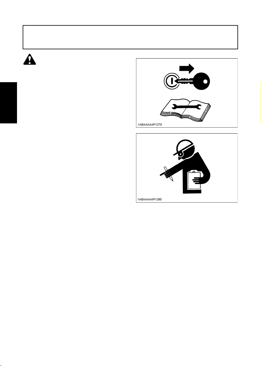
A Disconnect the battery from the engine before
conducting service. Put a "DO NOT OPERATE!" tag on
the key switch to avoid accidental starting.
A To avoid sparks from an accidental short circuit always
disconnect the battery's ground cable (-) first and
reconnect it last.
A Be sure to stop the engine and remove the key when
ENGLISH
conducting daily and periodic maintenance, service and
cleaning.
A Check or conduct maintenance after the engine,
coolant, muffler, or muffler cover have cooled off
completely.
A Always use the appropriate tools and fixtures. Verify that
they are in good condition before performing any service
work. Make sure you understand how to use them
before service.
A Use ONLY correct engine barring techniques for
manually rotating the engine. DO NOT attempt to rotate
the engine by pulling or prying on the cooling fan and Vbelt. This practice can cause serious personal injury or
premature damage to the cooling fan and belt.
A Replace fuel pipes and lubricant pipes with their hose
clamps every 2 years or earlier whether they are
damaged or not. They are made of rubber and age
gradually.
A When servicing is performed together by two or more
persons, take care to perform all work safely.
A Keep a first aid kit and fire extinguisher handy at all
times.
Page 11
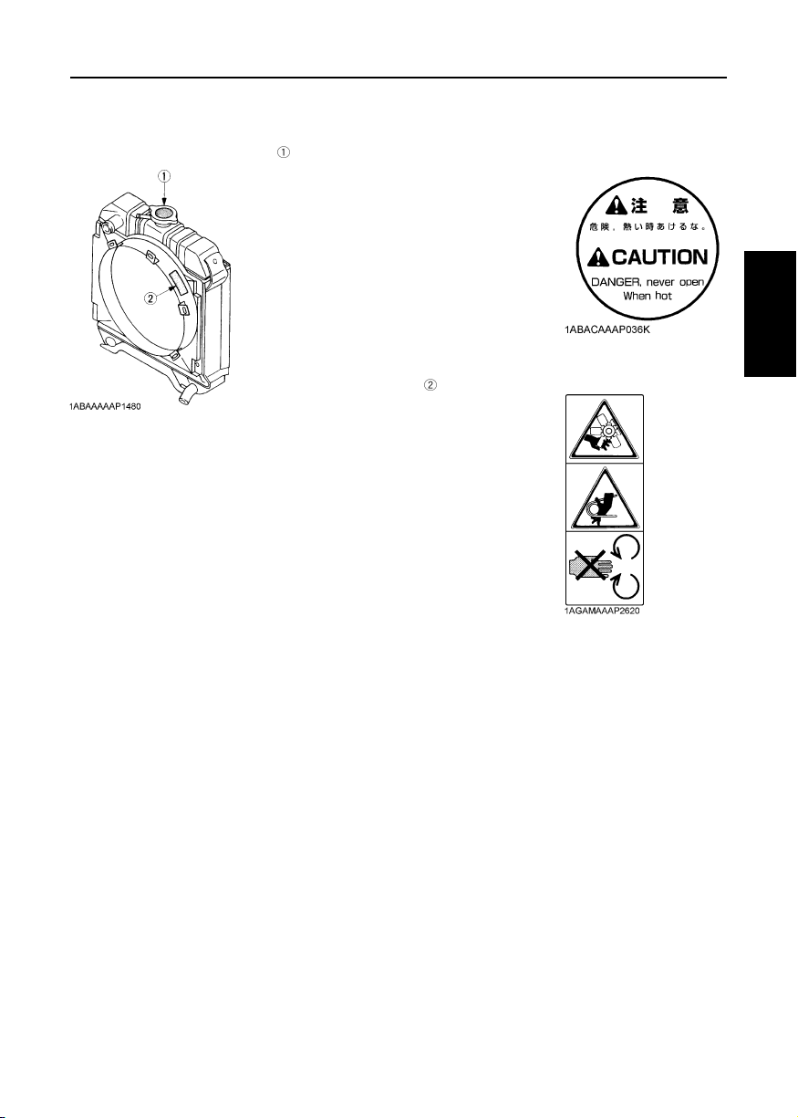
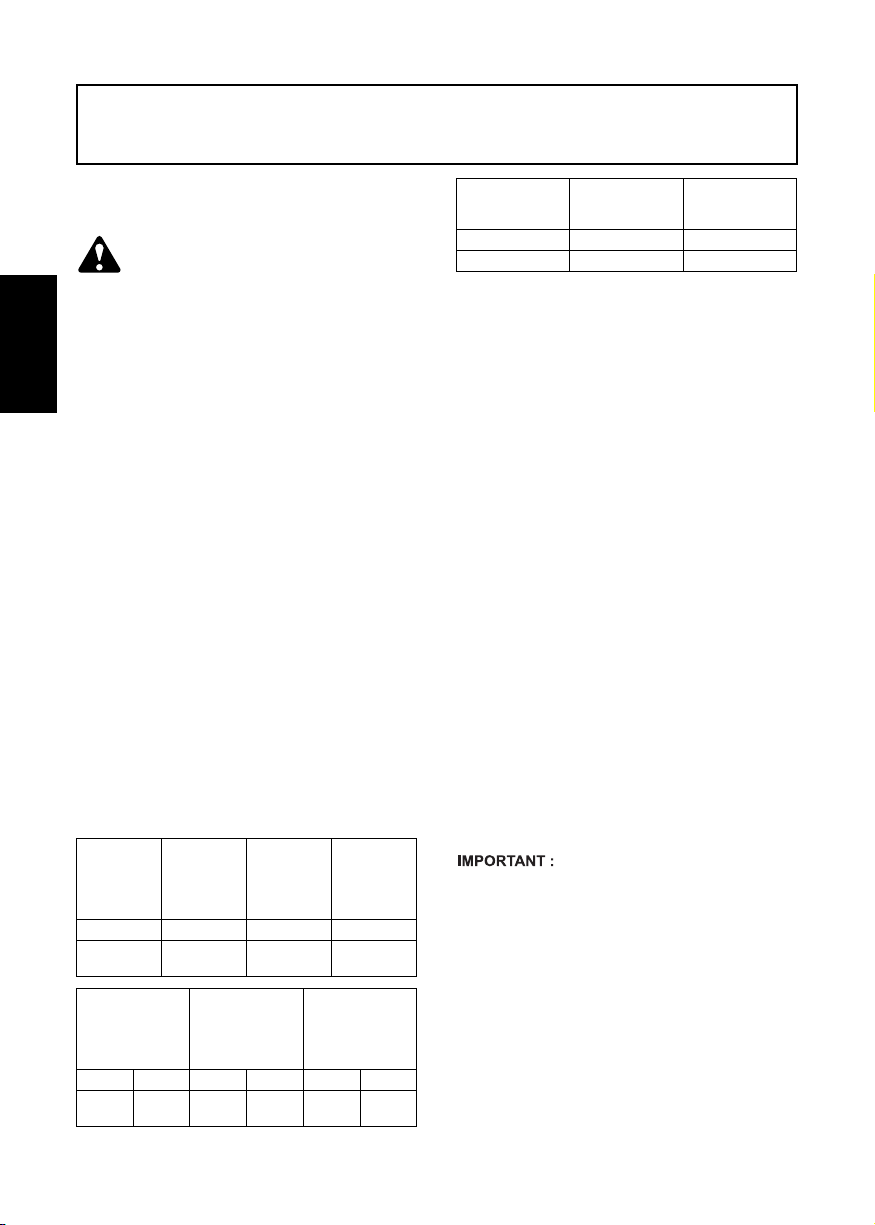
12. WARNING AND CAUTION LABELS
Part No.19077-8724-1 or 16667-8724-1
(55mm in diameter) (37mm in diameter)
Part No.TA040-4957-1
Stay clear of engine
fan and fan belt
7SAFE OPERATION
ENGLISH
13. CARE OF WARNING AND CAUTION LABELS
1. Keep warning and caution labels clean and free from obstructing material.
2. Clean warning and caution labels with soap and water, dry with a soft cloth.
3. Replace damaged or missing warning and caution labels with new labels from your local
KUBOTA dealer.
4. If a component with warning and caution label(s) affixed is replaced with a new part, make
sure the new label(s) is (are) attached in the same location(s) as the replaced component.
5. Mount new warning and caution labels by applying to a clean dry surface and pressing any
bubbles to the outside edge.
Page 12
SERVICING OF THE ENGINE
1SERVICING OF THE ENGINE
Your dealer is interested in your new engine and has the
desire to help you get the most value from it. After
reading this manual thoroughly, you will find that you
can do some of the regular maintenance yourself.
However, when in need of parts or major service, be
sure to see your KUBOTA dealer.
For service, contact the KUBOTA Dealership from
which you purchased your engine or your local
KUBOTA dealer.
When in need of parts, be prepared to give your dealer
the engine serial number.
Locate the serial number now and record them in the
space provided.
Type Serial No.
Engine
Date of Purchase
Name of Dealer
(To be filled in by purchaser)
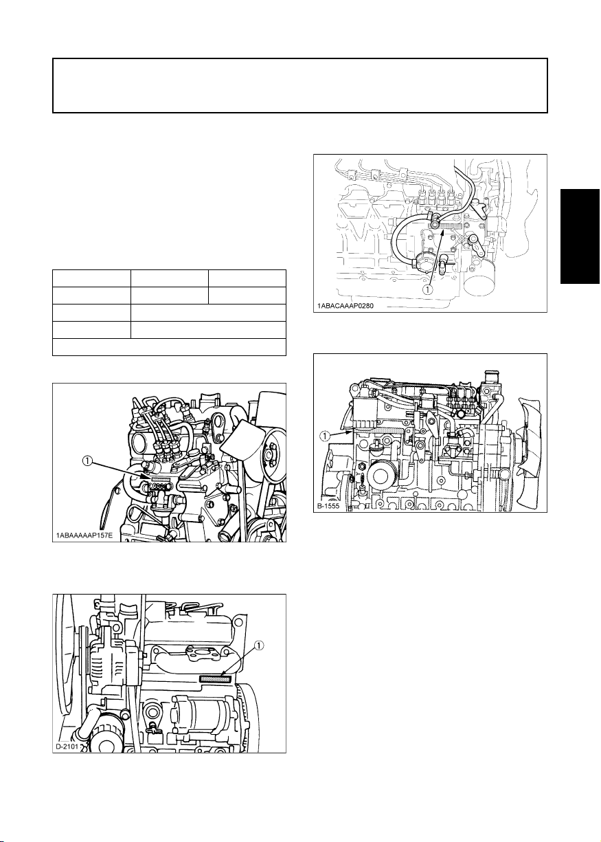
[Z482-E3, Z602-E3, D722-E3, D782-E3, D902-E3]
[D1503-M-E3, D1703-M-E3, D1803-M-E3, V2003-M-E3,
V2203-M-E3, V2403-M-E3, V2403-M-T-E3, D1803-M-DI-E3,
V2403-M-DI-E3]
(1) Engine serial number
[V3600-E3, V3600-T-E3, V3300-E3BG, V3600-T-E3BG]
(1) Engine serial number
ENGLISH
(1) Engine serial number
[D1005-E3, D1105-E3, D1105-TE3, D1305-E3, V1505-E3,
V1505-TE3, D1005-E3BG, D1105-E3BG, V1505-E3BG]
(1) Engine serial number
Page 13
2 NAMES OF PARTS
NAMES OF PARTS
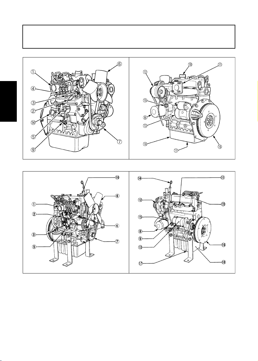
[Z482-E3, Z602-E3, D722-E3, D782-E3, D902-E3]
ENGLISH
1ABAAAAAP157F 1ABAAAAAP158E
[D1005-E3, D1105-E3, D1105-TE3, D1305-E3, V1505-E3, V1505-TE3, D1005-E3BG, D1105-E3BG, V1505-E3BG]
1ABABAAAP149A
(1) Intake manifold
(2) Speed control lever
(3) Engine stop lever
(4) Injection pump
(5) Fuel feed pump
(6) Cooling fan
(7) Fan drive pulley
(8) Oil filter cartridge
(9) Water drain cock
(10) Oil filler plug
(11) Exhaust manifold
(12) Alternator
(13) Starter
(14) Oil level gauge
(15) Oil pressure switch
(16) Flywheel
(17) Oil drain plug
(18) Oil pan
(19) Engine hook
Page 14
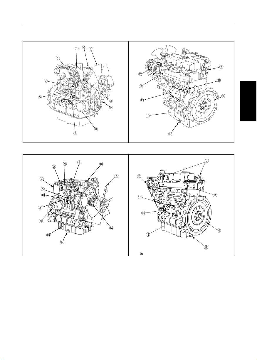
[D1503-M-E3, D1703-M-E3, D1803-M-E3, V2003-M-E3, V2203-M-E3, V2403-M-E3, V2403-M-T-E3, D1803-M-DI-E3,
V2403-M-DI-E3]
1ABACAAAP0020 1ABACAAAP0300
[V3600-E3, V3600-T-E3, V3300-E3BG, V3600-T-E3BG]
3NAMES OF PARTS
ENGLISH
B-1556 B-1543
(1) Intake manifold
(2) Speed control lever
(3) Engine stop lever
(4) Shut off solenoid
(5) Fuel feed pump
(6) Cooling fan
(7) Engine hook
(8) Oil filter cartridge
(9) Fuel filter
(10) Oil filler plug
(11) Exhaust manifold
(12) Alternator
(13) Starter
(14) Fan belt
(15) Oil pressure switch
(16) Flywheel
(17) Oil drain plug
(18) Oil pan
Page 15
4 PRE-OPERATION CHECK
PRE-OPERATION CHECK
BREAK-IN
During the engine break-in period, observe the following by all means:
1. Change engine oil and oil filter cartridge after the first 50 hours of operation. (See "ENGINE OIL" in "PERIODIC
SERVICE" section.)
2. When ambient temperature is low, operate the machine after the engine has been completely warmed up.
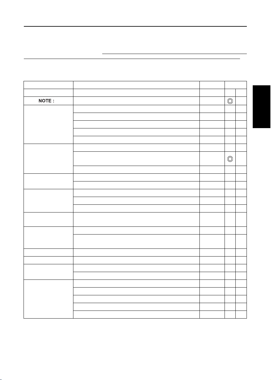
DAILY CHECK
To prevent trouble from occurring, it is important to know the conditions of the engine well. Check it before starting.
CAUTION
To avoid personal injury:
ENGLISH
A Be sure to install shields and safeguards attached to the engine when operating.
A Stop the engine at a flat and wide space when checking.
A Keep dust or fuel away from the battery, wiring, muffler and engine to prevent a fire.
Check and clear them before operating everyday. Pay attention to the heat of the
exhaust pipe or exhaust gas so that it can not ignite trash.
Item Ref. page
1. Parts which had trouble in previous operation -
2. By walking around the machine (1) Oil or water leaks 23 to 31
(2) Engine oil level and contamination 23
(3) Amount of fuel 18
(4) Amount of coolant 27 to 31
(5) Dust in air cleaner dust cup 32
(6) Damaged parts and loosened bolts and nuts -
3. By inserting the key into the starter
switch
4. By starting the engine (1) Color of exhaust fumes 9
(1) Proper functions of meters and pilot lamps; no stains on
these parts
(2) Proper function of glow lamp timer -
(2) Unusual engine noise 9
(3) Engine start-up condition 5
(4) Slow-down and acceleration behavior 9
-
Page 16
OPERATING THE ENGINE
5OPERATING THE ENGINE
STARTING THE ENGINE (NORMAL)
CAUTION
To avoid personal injury:
A Do not allow children to approach
the machine while the engine is
running.
A Be sure to install the machine on
which the engine is installed, on a
flat place.
A Do not run the engine on gradients.
A Do not run the engine in an enclosed
area. Exhaust gas can cause air
pollution and exhaust gas poisoning.
A Keep your hands away from rotating
parts (such as fan, pulley, belt,
flywheel etc.) during operation.
A Do not operate the machine while
under the influence of alcohol or
drugs.
A Do not wear loose, torn or bulky
clothing around the machine. It may
catch on moving parts or controls,
leading to the risk of accident. Use
additional safety items, e.g. hard
hat, safety boots or shoes, eye and
hearing protection, gloves, etc., as
appropriate or required.
A Do not wear radio or music
headphones while operating engine.
A Check to see if it is safe around the
engine before starting.
A Reinstall safeguards and shields
securely and clear all maintenance
tools when starting the engine after
maintenance.
1. Set the fuel lever to the "ON" position.
(1) Fuel lever (A) "ON"
2. Place the engine stop lever to the
"START" position.
3. Place the speed control lever at more
than half "OPERATION".
[Z482-E3, Z602-E3, D722-E3, D782-E3, D902-E3]
(B) "OFF"
ENGLISH
A Do not use ether or any starting fluid for starting the
engine, or a severe damage will occur.
A When starting the engine after a long storage (of
more than 3 months), first set the stop lever to the
"STOP" position and then activate the starter for
about 10 seconds to allow oil to reach every engine
part.
(1) Speed control lever (A) "OPERATION"
(B) "IDLING"
Page 17
6 OPERATING THE ENGINE
[D1005-E3, D1105-E3, D1105-TE3, D1305-E3, V1505-E3,
V1505-TE3]
(1) Speed control lever
ENGLISH
(2) Engine stop lever
[D1503-M-E3, D1703-M-E3, D1803-M-E3, V2003-M-E3,
V2203-M-E3, V2403-M-E3, V2403-M-T-E3, D1803-M-DI-E3,
(A) "IDLING"
(B) "OPERATION"
(C) "START"
(D) "STOP"
V2403-M-DI-E3]
[V3600-E3, V3600-T-E3]
(1) Speed control lever
(2) Engine stop lever
(A) "IDLING"
(B) "OPERATION"
(C) "START"
(D) "STOP"
4. Insert the key into the key switch and
turn it "ON".
(1) Engine stop lever
(2) Speed control lever
(A) "STOP"
(B) "START"
(C) "IDLING"
(D) "OPERATION"
(A) "SWITCHED OFF"
(B) "OPERATION"
(C) "PREHEATING"
(D) "STARTING"
(A) "PREHEATING"
(B) "SWITCHED OFF"
(C) "OPERATION"
(D) "STARTING"
5. Turn the starter switch to the
"PREHEATING" position to allow the
glow lamp to redden.
(with lamp timer in use)
A The glow lamp goes out in about 5 seconds when
the lamp timer is up. Refer to this for pre-heating.
Even with the glow lamp off, the glow plug can be
pre-heated by turning the starter switch to the
"PREHEATING" position.
Page 18
7OPERATING THE ENGINE
6. Turn the key to the "STARTING"
position and the engine should start.
Release the key immediately when the
engine starts.
7. Check to see that the oil pressure lamp
and charge lamp are off. If the lamps are
still on, immediately stop the engine,
and determine the cause.
(See "CHECKS DURING OPERATION" in
"OPERATING THE ENGINE" Section.)
A If the oil pressure lamp should be still on,
immediately stop the engine and check;
- if there is enough engine oil.
- if the engine oil has dirt in it.
- if the wiring is faulty.
8. Warm up the engine at medium speed
without load.
A If the glow lamp should redden too quickly or too
slowly, immediately ask your KUBOTA dealer to
check and repair it.
A If the engine does not catch or start at 10 seconds
after the starter switch is set at "STARTING"
position, wait for another 30 seconds and then begin
the engine starting sequence again. Do not allow the
starter motor to run continuously for more than 20
seconds.
COLD WEATHER STARTING
If the ambient temperature is below -5°C(23°F)* and the
engine is very cold, start it in the following manner:
Take steps (1) through (4) before.
5. Turn the key to the "PREHEATING"
position and keep it there for a certain
period mentioned below.
A Shown below are the standard preheating times for
various temperatures. This operation, however, is
not required, when the engine is warmed up.
Ambient
temperature
Above 10°C (50°F)
10°C (50°F) to
-5°C (23°F)
*Below -5°C (23°F)
Limit of
continuous use
Ordinary heat type
Approx. 5 seconds
Approx. 10 seconds
Preheating time
With glow lamp timer
NO NEED
See
20 seconds
A In case of installing standard glow lamp, glow lamp
goes off after about 6 seconds, when the starter
switch key is turned to preheating position. However
if necessary, keep the starter switch key at
preheating position for longer time, according to the
left recommendation.
6. Turn the key to the "STARTING"
position and the engine should start.
(If the engine fails to start after 10 seconds,
turn off the key for 5 to 30 seconds. Then
repeat steps (5) and (6).)
A Do not allow the starter motor to run continuously for
more than 20 seconds.
A Be sure to warm up the engine, not only in winter, but
also in warmer seasons. An insufficiently warmed-up
engine can shorten its service life.
A When there is fear of temperature dropping below
-15°C (5°F) detach the battery from the machine,
and keep it indoors in a safe area, to be reinstalled
just before the next operation.
STOPPING THE ENGINE
1. Return the speed control lever to low
idle, and run the engine under idling
conditions.
E3, D902-E3, D1005-E3, D1105-E3, D1105-TE3,
D1305-E3, V1505-E3, V1505-TE3, D1503-M-E3,
D1703-M-E3, D1803-M-E3, V2003-M-E3, V2203-ME3, V2403-M-E3, V2403-M-T-E3, D1803-M-DI-E3,
V2403-M-DI-E3, V3600-E3, V3600-T-E3]
2. Set the engine stop lever to the "STOP"
position.
3. With the starter switch placed to the
"OFF" position, remove the key. (Be
sure to return the engine stop lever to
the "START" position to be ready for the
next start.)
[Z482-E3, Z602-E3, D722-E3, D782-
ENGLISH
Page 19

8 OPERATING THE ENGINE
[Z482-E3, Z602-E3, D722-E3, D782-E3, D902-E3]
(1) Speed control lever
(2) Engine stop lever
ENGLISH
[D1005-E3, D1105-E3, D1105-TE3, D1305-E3, V1505-E3,
V1505-TE3]
(1) Speed control lever
(2) Engine stop lever
[D1503-M-E3, D1703-M-E3, D1803-M-E3, V2003-M-E3,
V2203-M-E3, V2403-M-E3, V2403-M-T-E3, D1803-M-DI-E3,
V2403-M-DI-E3]
(1) Engine stop lever
(2) Speed control lever
(A) "IDLING"
(B) "OPERATION"
(C) "START"
(D) "STOP"
(A) "IDLING"
(B) "OPERATION"
(C) "START"
(D) "STOP"
(A) "STOP"
(B) "START"
(C) "IDLING"
(D) "OPERATION"
[V3600-E3, V3600-T-E3]
(1) Speed control lever
(2) Engine stop lever
A If equipped with a turbo-charger, allow the engine to
idle for 5 minutes before shutting it off after a full load
operation.
Failure to do so may lead to turbo-charger trouble.
(A) "IDLING"
(B) "OPERATION"
(C) "START"
(D) "STOP"
CHECKS DURING OPERATION
While running, make the following checks to see that all
parts are working correctly.
BRadiator cooling water (Coolant)
WARNING
To avoid personal injury:
A Do not remove radiator cap until
coolant temperature is well below
its boiling point. Then loosen cap
slightly to the stop position, to
relieve any pressure, before
removing cap completely.
If the coolant temperature warning lamp lights up or if
steam or coolant does not stop squirting from the
radiator overflow pipe, turn off the load and keep the
engine idling (COOLING-DOWN) for at least 5
minutes to let it cool down gradually. Then stop the
engine and take the following inspection and servicing.
1. Check to see if the coolant runs short or if there is
any coolant leak;
2. Check to see if there is any obstacle around the
cooling air inlet or outlet;
3. Check to see if there is any dirt or dust between
radiator fins and tube;
4. Check to see if the fan belt is too loose;
5. Check to see if radiator water pipe is clogged; and
6. Check to see if anti-freeze is mixed to a 50/50% mix
of water and anti-freeze.
Page 20

9OPERATING THE ENGINE
BOil pressure lamp
The lamp lights up to warn the operator that the engine
oil pressure has dropped below the prescribed level. If
this should happen during operation or should not go off
even after the engine is accelerated more than
1000rpm, immediately stop the engine and check the
following:
1. Engine oil level (See "ENGINE OIL" in "PERIODIC
SERVICE" Section.)
2. Lubricant system (See "ENGINE OIL" in "PERIODIC
SERVICE" Section.)
BFuel
CAUTION
To avoid personal injury:
A Fluid escaping from pinholes may
be invisible. Do not use hands to
search for suspected leaks; Use a
piece of cardboard or wood,
instead. If injured by escaping fluid,
see a medical doctor at once. This
fluid can produce gangrene or a
severe allergic reaction.
A Check any leaks from fuel pipes or
fuel injection pipes. Use eye
protection when checking for leaks.
Be careful not to empty the fuel tank. Otherwise air may
enter the fuel system, requiring fuel system bleeding.
(See "FUEL" in "PERIODIC SERVICE" Section.)
BColor of exhaust
While the engine is run within the rated output range:
A The color of exhaust remains colorless.
A If the output slightly exceeds the rated level, exhaust
may become a little colored with the output level kept
constant.
A If the engine is run continuously with dark exhaust
emission, it may lead to trouble with the engine.
REVERSED ENGINE REVOLUTION AND
REMEDIES
CAUTION
To avoid personal injury:
A Reversed engine operation can
make the machine reverse and run it
backwards. It may lead to serious
trouble.
A Reversed engine operation may
make exhaust gas gush out into the
intake side and ignite the air
cleaner; It could catch fire.
Reversed engine revolution must be stopped
immediately since engine oil circulation is cut quickly,
leading to serious trouble.
BHow to tell when the engine starts running
backwards
1. Lubricating oil pressure drops sharply. Oil pressure
warning light, if used, will light.
2. Since the intake and exhaust sides are reversed, the
sound of the engine changes, and exhaust gas will
come out of the air cleaner.
3. A louder knocking sound will be heard when the
engine starts running backwards.
BRemedies
1. Immediately set the engine stop lever to the "STOP"
position to stop the engine.
2. After stopping the engine, check the air cleaner,
intake rubber tube and then other parts and replace
parts as needed.
ENGLISH
BImmediately stop the engine if;
A The engine suddenly slows down or accelerates.
A Unusual noises are suddenly heard.
A Exhaust fumes suddenly become very dark.
A The oil pressure lamp or the water temperature
alarm lamp lights up.
Page 21
10 MAINTENANCE
MAINTENANCE
CAUTION
To avoid personal injury:
A Be sure to conduct daily checks,
periodic maintenance, refueling or
cleaning on a level surface with the
engine shut off and remove the key.
A Before allowing other people to use
your engine, explain how to operate,
and have them read this manual
ENGLISH
before operation.
A When cleaning any parts, do not use
gasoline but use regular cleanser.
A Always use proper tools, that are in
good condition. Make sure you
understand how to use them, before
performing any service work.
A When installing, be sure to tighten
all bolts lest they should be loose.
Tighten the bolts by the specified
torque.
A Do not put any tools on the battery,
or battery terminals may short out.
Severe burns or fire could result.
Detach the battery from the engine
before maintenance.
A Do not touch muffler or exhaust
pipes while they are hot; Severe
burns could result.
Page 22
11MAINTENANCE
SERVICE INTERVALS
Observe the following for service and maintenance.
The lubricating oil change intervals listed in the table below are for Classes CG-4, CH-4, CI-4 and CF lubricating oil of API
classification with a low-sulfur fuel in use. If the CG-4, CH-4 or CI-4 lubricating oil is used with a high-sulfur fuel, change
the lubricating oil at shorter intervals than recommended in the table below depending on the operating condition.
[Z482-E3, Z602-E3, D722-E3, D782-E3, D902-E3, D1005-E3, D1105-E3, D1105-TE3, D1305-E3, V1505-E3, V1505-TE3,
D1503-M-E3, D1703-M-E3, D1803-M-E3, V2003-M-E3, V2203-M-E3, V2403-M-E3, V2403-M-T-E3, D1803-M-DI-E3,
V2403-M-DI-E3]
Interval Item
Every 50 hours Check of fuel pipes and clamp bands 21 @
See
Changing engine oil (depending on the oil pan) 23 to 26
Cleaning of air cleaner element 32 *1 @
Cleaning of fuel filter 22
Every 100 hours
Check of battery electrolyte level 35, 36
Check of fan belt tightness 37
Draining water separator -
Check of radiator hoses and clamp bands 30
Every 200 hours
Replacing the oil filter cartridge
(depending on the oil pan)
Check of intake air line - @
Every 400 hours
Replacement of fuel filter cartridge 23 @
Cleaning of water separator -
Removal of sediment in fuel tank -
Every 500 hours
Cleaning of water jacket (radiator interior) 27 to 31
Replacement of fan belt 37
Every one or two
months
Recharging of battery 35, 36
Replacement of air cleaner element 32 *2 @
Every year
Check of damage in electric wiring and loose
connections
Every 800 hours Check of valve clearance 39
Every 1500 hours Check of fuel injection nozzle injection pressure - *3 @
Every 3000 hours
Check of turbo charger - *3 @
Check of injection pump - *3 @
Change of radiator coolant (L.L.C.) 29 to 31
Replacement of battery 35, 36
Every two years
Replacement of radiator hoses and clamp bands 30
Replacement of fuel pipes and clamp bands 21 *3 @
Replacement of intake air line - *4 @
Ref. page
26
-
ENGLISH
Page 23

12 MAINTENANCE
[D1005-E3BG, D1105-E3BG, V1505-E3BG]
Interval Item
Ref. page
Every 50 hours Check of fuel pipes and clamp bands 21 @
Cleaning of air cleaner element 32 *1 @
Cleaning of fuel filter 22
Every 100 hours
Check of battery electrolyte level 35, 36
Check of fan belt tightness 37
Draining water separator -
Check of radiator hoses and clamp bands 30
Every 200 hours
Changing engine oil (depending on the oil pan) 23 to 26
Check of intake air line - @
ENGLISH
Every 400 hours
Replacing the oil filter cartridge 26
Replacement of fuel filter cartridge 23 @
Cleaning of water separator -
Removal of sediment in fuel tank -
Every 500 hours
Cleaning of water jacket (radiator interior) 27 to 31
Replacement of fan belt 37
Every one or two
months
Recharging of battery 35, 36
Replacement of air cleaner element 32 *2 @
Every year
Check of damage in electric wiring and loose
connections
-
Every 800 hours Check of valve clearance 39
Every 1500 hours Check of fuel injection nozzle injection pressure - *3 @
Every 3000 hours
Check of turbo charger - *3 @
Check of injection pump - *3 @
Change of radiator coolant (L.L.C.) 29 to 31
Replacement of battery 35, 36
Every two years
Replacement of radiator hoses and clamp bands 30
Replacement of fuel pipes and clamp bands 21 *3 @
Replacement of intake air line - *4 @
Page 24

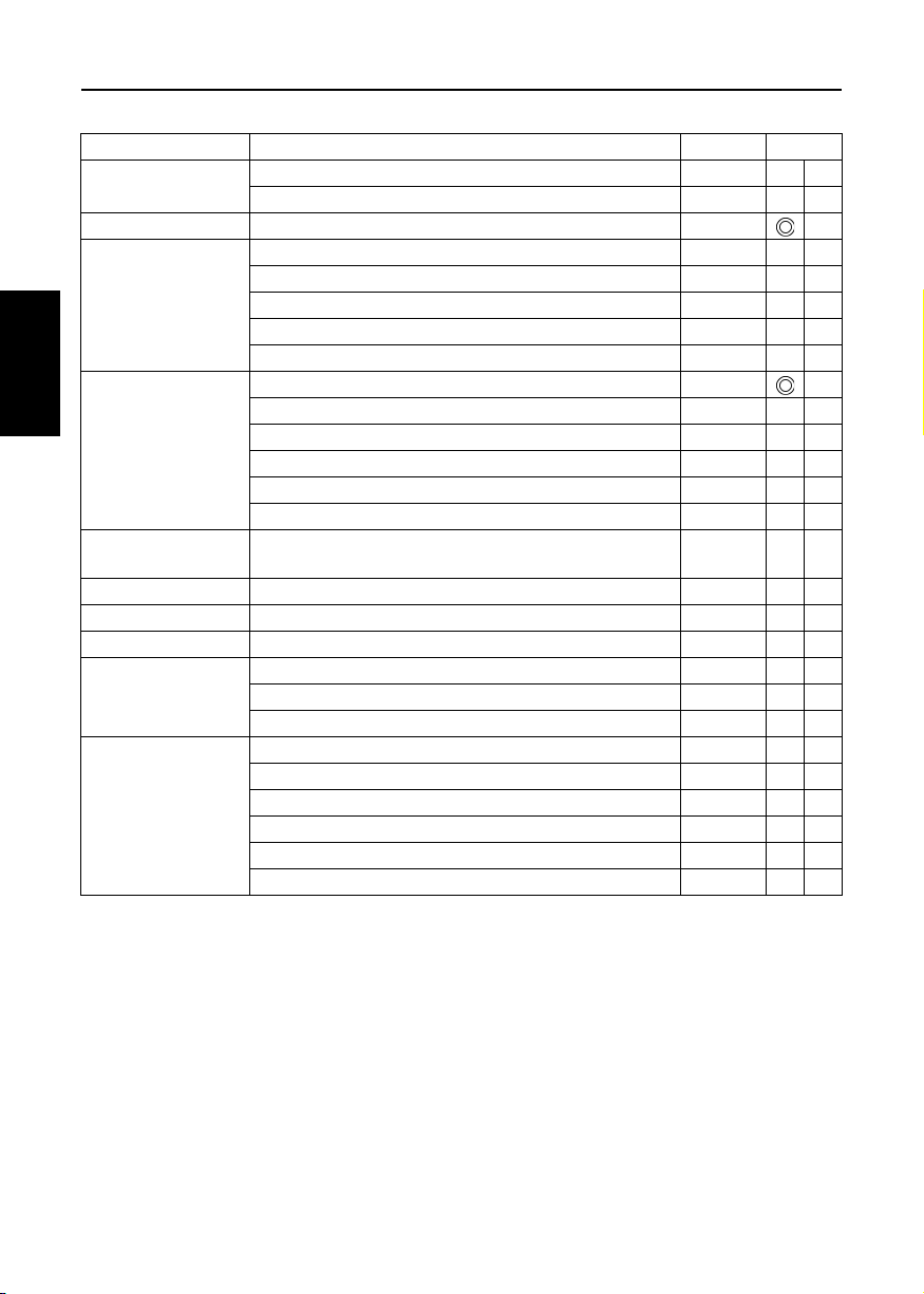
[V3600-E3, V3600-T-E3]
Interval Item
Every 50 hours
Check of fuel pipes and clamp bands 21 @
Draining water separator -
Ref. page
See Changing engine oil 23 to 26
Cleaning of air cleaner element 32 *1 @
Check of battery electrolyte level 35, 36
Every 250 hours
Check of fan belt tightness 37
Check of radiator hoses and clamp bands 30
Check of intake air line - @
Replacing the oil filter cartridge 26
Replacement of fuel filter cartridge 23 @
Every 500 hours
Removal of sediment in fuel tank -
Cleaning of water jacket (radiator interior) 27 to 31
Replacement of fan belt 37
Cleaning of water separator -
Every one or two
months
Recharging of battery 35, 36
Every year Replacement of air cleaner element 32 *2 @
Every 1000 hours Check of valve clearance 39
Every 1500 hours Check of fuel injection nozzle injection pressure - *3 @
Check of turbo charger - *3 @
Every 3000 hours
Check of injection pump - *3 @
Check of fuel injection timer - *3 @
Change of radiator coolant (L.L.C.) 29 to 31
Replacement of battery 35, 36
Every two years
Replacement of radiator hoses and clamp bands 30
Replacement of fuel pipes and clamp bands 21 *3 @
Replacement of intake air line - *4 @
Replacement of fan belt (or every 500 hours) 37
13MAINTENANCE
ENGLISH
Page 25
14 MAINTENANCE
[V3300-E3BG, V3600-T-E3BG]
Interval Item
Every 50 hours
Check of fuel pipes and clamp bands 21 @
Draining water separator -
Ref. page
Every 200 hours Changing engine oil 23 to 26
Cleaning of air cleaner element 32 *1 @
Check of battery electrolyte level 35, 36
Every 250 hours
Check of fan belt tightness 37
Check of radiator hoses and clamp bands 30
Check of intake air line - @
Replacing the oil filter cartridge 26
ENGLISH
Every 500 hours
Replacement of fuel filter cartridge 23 @
Removal of sediment in fuel tank -
Cleaning of water jacket (radiator interior) 27 to 31
Replacement of fan belt 37
Cleaning of water separator -
Every one or two
months
Recharging of battery 35, 36
Every year Replacement of air cleaner element 32 *2 @
Every 1000 hours Check of valve clearance 39
Every 1500 hours Check of fuel injection nozzle injection pressure - *3 @
Check of turbo charger - *3 @
Every 3000 hours
Check of injection pump - *3 @
Check of fuel injection timer - *3 @
Change of radiator coolant (L.L.C.) 29 to 31
Replacement of battery 35, 36
Every two years
Replacement of radiator hoses and clamp bands 30
Replacement of fuel pipes and clamp bands 21 *3 @
Replacement of intake air line - *4 @
Replacement of fan belt (or every 500 hours) 37
Page 26

15MAINTENANCE
A The jobs indicated by must be done after the first 50 hours of operation.
*1 Air cleaner should be cleaned more often in dusty conditions than in normal conditions.
*2 After 6 times of cleaning.
*3 Consult your local KUBOTA Dealer for this service.
*4 Replace only if necessary.
A When the battery is used for less than 100 hours in a year, check its electrolyte yearly. (for refillable battery's only)
A The items listed above (@ marked) are registered as emission related critical parts by KUBOTA in the U.S. EPA
nonroad emission regulation. As the engine owner, you are responsible for the performance of the required
maintenance on the engine according to the above instruction.
Please see the Warranty Statement in detail.
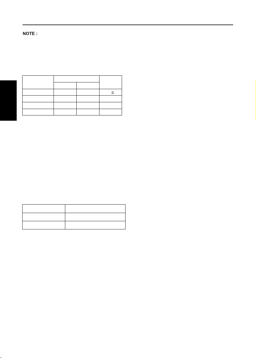
A Changing interval of engine oil and oil filter cartridge
Models
Z602-E3, D902-E3 101 mm (3.98 in.) 100 Hrs
Z482-E3, D722-E3
D782-E3 121 mm (4.76 in.) 100 Hrs
D1005-E3, D1105-E3,
D1105-TE3, D1305-E3,
Engine oil
Oil filter cartridge
*1: 101 mm (3.98 in.) oil pan depth is optional for Z482-E3 and D722-E3.
*2: 101 mm oil pan depth is optional.
*3: 90 mm (3.54 in.) oil pan depth is optional.
A Standard replacement interval
* American Petroleum Institute (API) classification: above CF
V1505-E3, V1505-TE3,
D1005-E3BG, D1105-E3BG
V1505-E3BG
D1503-M-E3, D1703-M-E3,
D1803-M-E3, V2003-M-E3,
V2203-M-E3, V2403-M-E3,
V2403-M-T-E3
D1803-M-DI-E3,
V2403-M-DI-E3
V3600-E3, V3600-T-E3,
V3600-E3BG, V3600-T-E3BG
Z602-E3, D902-E3 101 mm (3.98 in.) 200 Hrs
Z482-E3, D722-E3
D782-E3 121 mm (4.76 in.) 200 Hrs
D1005-E3, D1105-E3,
D1105-TE3, D1305-E3,
V1505-E3, V1505-TE3
D1005-E3BG, D1105-E3BG
V1505-E3BG
D1503-M-E3, D1703-M-E3,
D1803-M-E3, V2003-M-E3
V2203-M-E3, V2403-M-E3,
V2403-M-T-E3
D1803-M-DI-E3,
V2403-M-DI-E3
V3600-E3, V3600-T-E3,
V3600-E3BG, V3600-T-E3BG
101 mm (3.98 in.) *1 75 Hrs
121 mm (4.76 in.) 100 Hrs
Above 125 mm (4.9 in.)
(110 mm D1305-E3)
Below 101 mm (4.0 in.) *2 150 Hrs
124 mm (4.88 in.) 200 Hrs
90 mm (3.54 in.) *3 150 Hrs
124 mm (4.88 in.) 400 Hrs
250 Hrs or 1 year whichever comes first
101 mm (3.98 in.) *1 150 Hrs
121 mm (4.76 in.) 200 Hrs
Above 125 mm (4.9 in.)
(110 mm D1305-E3)
Below 101 mm (4.0 in.) *2 150 Hrs
124 mm (4.88 in.) 200 Hrs
90 mm (3.54 in.) *3 150 Hrs
124 mm (4.88 in.) 400 Hrs
* Ambient temperature: below 35°C (95°F)
Interval
Oil pan depth
Oil pan depth
500 Hrs
200 Hrs
200 Hrs
Initial
50 Hrs
50 Hrs
ENGLISH
Page 27
16 MAINTENANCE
Lubricating oil
With strict emission control regulations now in effect, the CG-4, CH-4 and CI-4 engine oils have been developed
for use with low sulfur fuels, for On-Highway vehicle engines. When a Non-Road engine runs on high sulfur fuel,
it is advisable to use a "CF or better" classification engine oil with a high Total Base Number (a minimum TBN of
10 is recommended).
A Lubricating oil recommended when a low-sulfur or high-sulfur fuel is employed.
{ : Recommendable : Not recommendable
Lubricating
oil classification
CF {{*TBN 10
CG-4 {
CH-4 {
ENGLISH
CI-4 {
*TBN: Total Base Number
**Fuel
A Diesel Fuel Specification Type and Sulfur Content % (ppm) used, must be compliant with all applicable emission
regulations for the area in which the engine is operated.
A Use of diesel fuel with sulfur content less than 0.10 % (1000 ppm) is strongly recommended.
A If high-sulfur fuel (sulfur content 0.50 % (5000 ppm) to 1.0 % (10000 ppm)) is used as a diesel fuel, change the
engine oil and oil filter at shorter intervals. (approximately half)
A DO NOT USE Fuels that have sulfur content greater than 1.0 % (10000 ppm).
A Since KUBOTA diesel engines of less than 56 kW (75 hp) utilize EPA Tier 4 and Interim Tier 4 standards, the use
of ultra low sulfur fuel is mandatory for these engines, when operated in US EPA regulated areas. Therefore, please
use No.2-D S15 diesel fuel as an alternative to No.2-D, and use No.1-D S15 diesel fuel as an alternative to No.1D for ambient temperatures below -10°C (14°F).
No.1-D or No.2-D, S15 : Ultra Low Sulfur Diesel (ULSD) 15 ppm or 0.0015 wt.%
A CJ-4 classification oil is intended for use in engines equipped with DPF (Diesel Particulate Filter) and is Not
Recommended for use in Kubota E3 specification engines.
A Oil used in the engine should have API classification and Proper SAE Engine Oil according to the ambient
temperatures as shown below:
Above 25°C (77°F) SAE30, SAE10W-30 or 15W-40
-10 to 25°C (14°F to 77°F)
Below -10°C (14°F)
**Fuel
Low-sulfur High-sulfur
SAE10W-30 or 15W-40
SAE10W-30
Remarks
Page 28

A Recommended API classification
Refer to the following table for the suitable American Petroleum Institute (API) classification of engine oil according
to the engine type (with internal EGR, external EGR or non-EGR) and the Fuel Type Used : (Ultra Low Sulfur or
High Sulfur Fuels).
Engine oil classification (API classification)
Fuel type
High Sulfur Fuel
[0.05 % (500 ppm)
Sulfur Content <
0.50 % (5000 ppm)]
CF
(If the "CG-4, CH-4 or CI-4" engine oil is used with a
high-sulfur fuel, change the engine oil at shorter
intervals. (approximately half))
Engines with non-EGR
Engines with internal EGR
Engines with external EGR
---
17MAINTENANCE
Ultra Low Sulfur Fuel
[Sulfur Content <
0.0015 % (15 ppm)]
CF, CG-4, CH-4 or CI-4
EGR: Exhaust Gas Re-circulation
CF
(Class CG-4, CH-4 and CI-4 engine, oils
cannot be used on EGR type engines.)
ENGLISH
Page 29
18 PERIODIC SERVICE
PERIODIC SERVICE
FUEL
Fuel is flammable and can be dangerous. You should
handle fuel with care.
CAUTION
To avoid personal injury:
A Do not mix gasoline or alcohol with
diesel fuel. This mixture can cause
an explosion.
A Be careful not to spill fuel during
ENGLISH
refueling. If fuel should spill, wipe it
off at once, or it may cause a fire.
A Do not fail to stop the engine before
refueling. Keep the engine away
from the fire.
A Be sure to stop the engine while
refueling or bleeding and when
cleaning or changing fuel filter or
fuel pipes. Do not smoke when
working around the battery or when
refueling.
A Check the fuel systems at a well
ventilated and wide place.
A When fuel and lubricant are spilled,
refuel after letting the engine cool
off.
A Always keep spilled fuel and lubricant
away from engine.
BFuel level check and refueling
1. Check to see that the fuel level is above the lower
limit of the fuel level gauge.
2. If the fuel is too low, add fuel to the upper limit. Do
not overfill.
Carbon
Residue on,
10 percent
Residuum,
%
Viscosity
Kinematic
cSt or
2
mm
/s at
40°C
1.9 4.1 32.6 40.1
Viscosity
Saybolt,
SUS at
37.8°C(100°F)
°C(°F)
90%
Point
Water and
Sediment,
volume
%
0.05 0.35 0.01
338
(640)
Flash Point,
°C
(°F)
Min Max Max Max
52
(125)
Distillation
Temperatures,
Min Max Min Max Min Max
282
(540)
Ash,
weight
%
Sulfur,
weight
%
Max Max Min
0.50 No. 3 40
A Cetane Rating : The minimum recommended Fuel
Cetane Rating is 45. A cetane rating greater than 50
is preferred, especially for ambient temperatures
below -20 °C (-4 °F) or elevations above 1500 m
(5000 ft).
A Diesel Fuel Specification Type and Sulfur Content %
(ppm) used, must be compliant with all applicable
emission regulations for the area in which the engine
is operated.
A Use of diesel fuel with sulfur content less than 0.10 %
(1000 ppm) is strongly recommended.
A If high-sulfur fuel (sulfur content 0.50 % (5000 ppm)
to 1.0 % (10000 ppm)) is used as a diesel fuel,
change the engine oil and oil filter at shorter
intervals. (approximately half)
A DO NOT USE Fuels that have sulfur content greater
than 1.0 % (10000 ppm).
A Diesel fuels specified to EN 590 or ASTM D975 are
recommended.
A No.2-D is a distillate fuel of lower volatility for
engines in industrial and heavy mobile service. (SAE
J313 JUN87)
A Since KUBOTA diesel engines of less than 56 kW
(75 hp) utilize EPA Tier 4 and Interim Tier 4
standards, the use of ultra low sulfur fuel is
mandatory for these engines, when operated in US
EPA regulated areas. Therefore, please use No.2-D
S15 diesel fuel as an alternative to No.2-D, and use
No.1-D S15 diesel fuel as an alternative to No.1-D
for ambient temperatures below -10 °C (14 °F).
1) SAE : Society of Automotive Engineers
2) EN : European Norm
3) ASTM : American Society of Testing and Materials
4) US EPA : United States Environmental
Protection Agency
5) No.1-D or No.2-D, S15 : Ultra Low Sulfur Diesel
(ULSD) 15 ppm or 0.0015 wt.%
A Be sure to use a strainer when filling the fuel tank, or
dirt or sand in the fuel may cause trouble in the fuel
injection pump.
A For fuel, always use diesel fuel. You are required not
to use alternative fuel, because its quality is
unknown or it may be inferior in quality. Kerosene,
which is very low in cetane rating, adversely affects
the engine. Diesel fuel differs in grades depending
on the temperature.
A Be careful not to let the fuel tank become empty, or
air can enter the fuel system, necessitating bleeding
before next engine start.
Copper
Strip
Corrosion
Cetane
Number
Page 30
19PERIODIC SERVICE
BAir bleeding the fuel system
CAUTION
To avoid personal injury;
A Do not bleed a hot engine as this
could cause fuel to spill onto a hot
exhaust manifold creating a danger
of fire.
Air bleeding of the fuel system is required if;
A after the fuel filter and pipes have been detached
and refitted;
A after the fuel tank has become empty; or
A before the engine is to be used after a long storage.
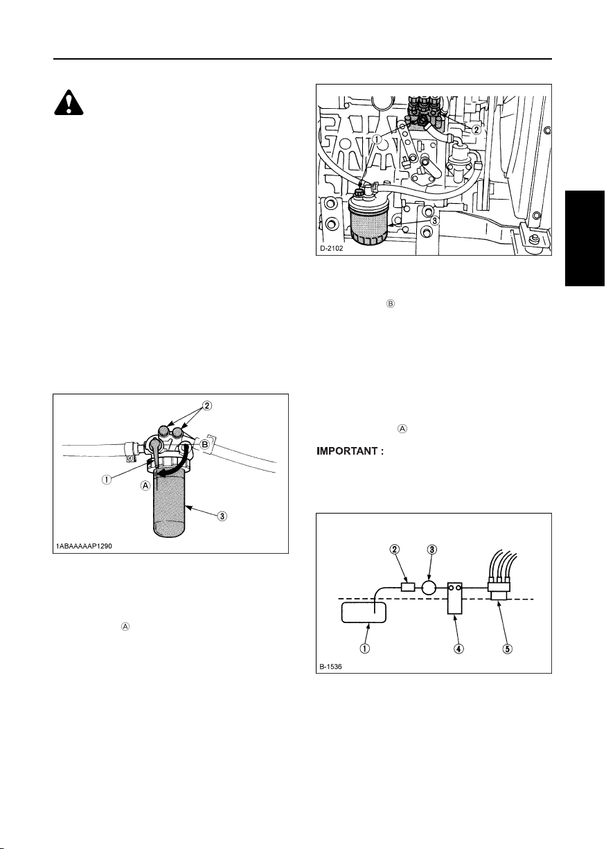
[Z482-E3, Z602-E3, D722-E3, D782-E3, D902-E3],
[PROCEDURE]
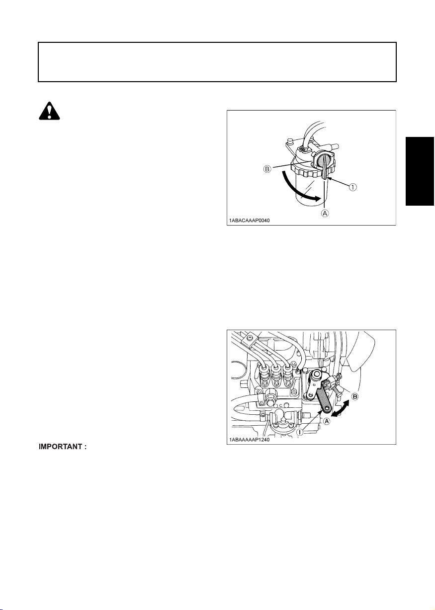
1. Fill the fuel tank to the fullest extent. Open the fuel
filter lever.
2. Loosen air vent plug of the fuel filter a few turns.
3. Screw back the plug when bubbles do not come up
any more.
4. Open the air vent plug on top of the fuel injection
pump.
5. Retighten the plug when bubbles do not come up
any more.
[GRAVITY FEED SYSTEM]
(1) Air vent plug
(2) Injection pump
(3) Fuel filter
[PROCEDURE ] (fuel tanks lower than injection
pump)
1. For fuel tanks that are lower than the injection pump.
The fuel system must be pressurized by the fuel
system electric fuel pump.
2. If an electric fuel pump is not used, you must
manually actuate the pump by lever to bleed.
3. The primary fuel filter must be on the pressure
side of the pump if the fuel tank is lower than the
injection pump.
4. To bleed follow (2) through (5) above.
(PROCEDURE )
A Tighten air vent plug of the fuel injection pump
except when bleeding, or it may stop the engine
suddenly.
[TANK BELOW INJECTION PUMP SYSTEM]
ENGLISH
(1) Fuel filter lever
(2) Air vent plug
(3) Fuel filter pot
[D1005-E3, D1105-E3, D1105-TE3, D1305-E3, V1505-E3,
V1505-TE3, D1005-E3BG, D1105-E3BG, V1505-E3BG]
[PROCEDURE ] (gravity feed fuel tanks only)
1. Fill the fuel tank to the fullest extent. Open the fuel
filter lever.
2. Loosen air vent plug of the fuel filter a few turns.
3. Screw back the plug when bubbles do not come up
any more.
4. Open the air vent plug on top of the fuel injection
pump.
5. Retighten the plug when bubbles do not come up
any more.
(A) "ON"
(B) "OFF"
(1) Fuel tank below injection pump
(2) Pre-filter
(3) Electric or Mechanical pump
(4) Main Filter
(5) Injection pump
Page 31
20 PERIODIC SERVICE
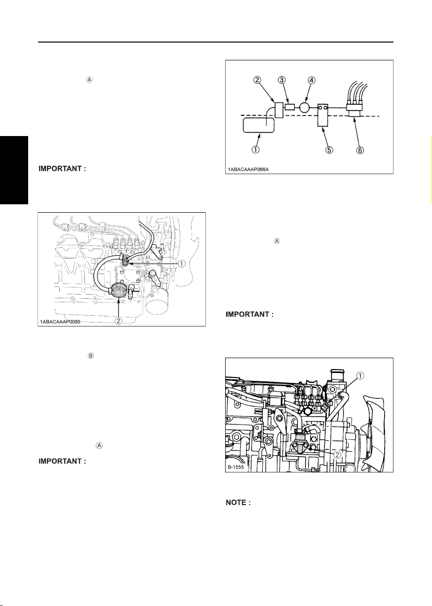
[D1503-M-E3, D1703-M-E3, D1803-M-E3, V2003-M-E3,
V2203-M-E3, V2403-M-E3, V2403-M-T-E3, D1803-M-DI-E3,
V2403-M-DI-E3]
[PROCEDURE ] (gravity feed fuel tanks only)
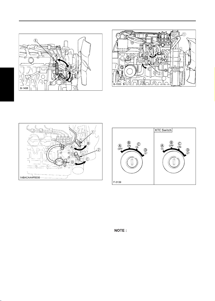
1. Fill the fuel tank to the fullest extent. Open the water
separator lever.
2. Open the air vent cock on top of the fuel injection
pump.
3. Turn the engine, continue it for about 10 seconds,
then stop it, or move the fuel pump lever by hand
(optional).
4. Close the air vent cock on top of the fuel injection
pump.
A Always keep the air vent cock on the fuel injection
pump closed except when air is vented, or it may
ENGLISH
cause the engine to stop.
[GRAVITY FEED SYSTEM]
(1) Air vent cock
(2) Fuel feed pump
[PROCEDURE ] (fuel tanks lower than injection
pump)
For fuel tanks that are lower than the injection pump.
1. The fuel system must be pressurized by the fuel
system electric fuel pump.
2. If an electric fuel pump is not used, you must
manually actuate the pump by lever to bleed.
3. The primary fuel filter must be on the pressure side
of the pump if the fuel tank is lower than the injection
pump.
4. To bleed, follow (2) through (4) above.
(PROCEDURE )
[TANK BELOW INJECTION PUMP SYSTEM]
(1) Fuel tank below injection pump
(2) Water separator
(3) Pre-filter
(4) Electric or Mechanical pump
(5) Main Filter
(6) Injection pump
[V3600-E3, V3600-T-E3, V3300-E3BG, V3600-T-E3BG]
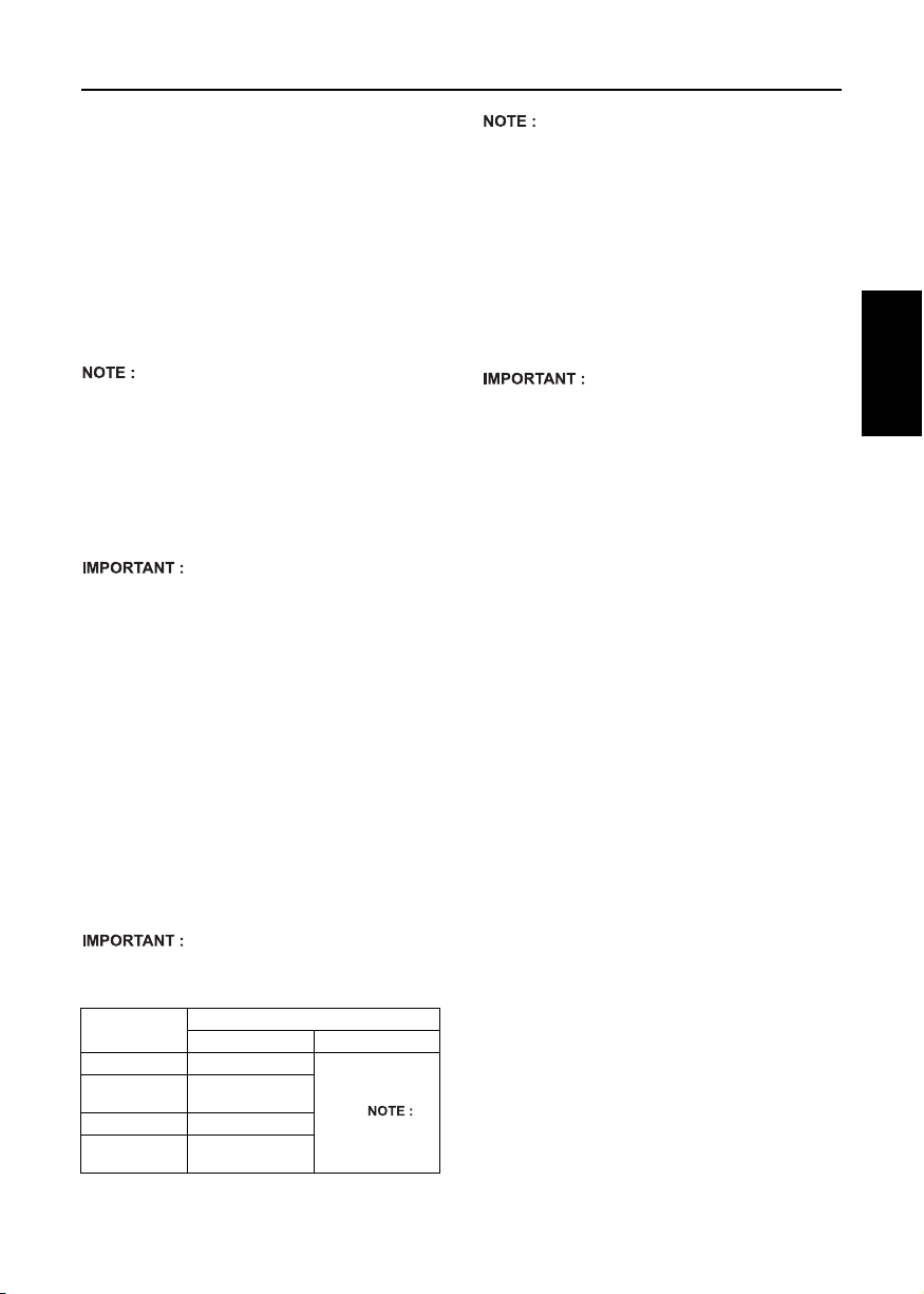
[PROCEDURE ] (gravity feed fuel tanks only)
1. Fill the fuel tank to the fullest extent. Open the fuel
filter lever.
2. Open the joint bolt on top of the fuel injection pump.
3. Turn the engine, continue it for about 10 seconds,
then stop it, or move the fuel feed pump lever by
hand (optional).
4. Close the Joint bolt on top of the fuel injection pump.
A Always keep the air vent cock on the fuel injection
pump closed except when air is vented, or it may
cause the engine to stop.
[GRAVITY FEED SYSTEM]
A Tighten air vent plug of the fuel injection pump
except when bleeding, or it may stop the engine
suddenly.
(1) Joint bolt
(2) Fuel feed pump
A For the engine equipped with automatic venting
(optional) no manual bleeding of fuel lines is
required.
Page 32

21PERIODIC SERVICE
[PROCEDURE ] (fuel tanks lower than injection
pump)
1. For fuel tanks that are lower than the injection pump.
The fuel system must be pressurized by the fuel
system electric fuel pump.
2. If an electric fuel pump is not used, you must
manually actuate the pump by lever to bleed.
3. The primary fuel filter must be on the pressure
side of the pump if the fuel tank is lower than the
injection pump.
4. To bleed follow (2) through (4) above.
(PROCEDURE )
A Tighten air vent plug of the fuel injection pump
except when bleeding, or it may stop the engine
suddenly.
[TANK BELOW INJECTION PUMP SYSTEM]
(1) Fuel tank below injection pump
(2) Water separator
(3) Pre-filter
(4) Electric or Mechanical pump
(5) Main Filter
(6) Injection pump
BChecking the fuel pipes
CAUTION
To avoid personal injury;
A Check or replace the fuel pipes after
stopping the engine. Broken fuel
pipes can cause fires.
Check the fuel pipes every 50 hours of operation. When
if;
1. If the clamp band is loose, apply oil to the screw of
the band, and tighten the band securely.
2. If the fuel pipes, made of rubber, became worn out,
replace them and clamp bands every 2 years.
3. If the fuel pipes and clamp bands are found worn or
damaged before 2 years' time, replace or repair
them at once.
4. After replacement of the pipes and bands, air-bleed
the fuel system.
A When the fuel pipes are not installed, plug them at
both ends with clean cloth or paper to prevent dirt
from entering. Dirt in the pipes can cause fuel
injection pump malfunction.
[Z482-E3, Z602-E3, D722-E3, D782-E3, D902-E3,
D1005-E3, D1105-E3, D1105-TE3, D1305-E3, V1505-E3,
V1505-TE3, D1005-E3BG, D1105-E3BG, V1505-E3BG]
ENGLISH
(1) Clamp band
(2) Fuel pipe
Page 33

22 PERIODIC SERVICE
[D1503-M-E3, D1703-M-E3, D1803-M-E3, V2003-M-E3,
V2203-M-E3, V2403-M-E3, V2403-M-T-E3, D1803-M-DI-E3,
V2403-M-DI-E3]
ENGLISH
(1) Clamp band
(2) Fuel pipe
[V3600-E3, V3600-T-E3, V3300-E3BG, V3600-T-E3BG]
BCleaning the fuel filter pot
Every 100 hours of operation, clean the fuel filter in a
clean place to prevent dust intrusion.
1. Close the fuel filter lever.
(1) Fuel filter lever
(2) Fuel filter pot
2. Remove the top cap, and rinse the inside with diesel
fuel.
3. Take out the element, and rinse it with diesel fuel.
4. After cleaning, reinstall the fuel filter, keeping out of
dust and dirt.
5. Air-bleed the injection pump.
A Entrance of dust and dirt can cause a malfunction of
the fuel injection pump and the injection nozzle.
Wash the fuel filter cup periodically.
(A) "OFF"
(B) "ON"
(1) Clamp band
(2) Fuel pipe
(1) O ring
(2) Filter element
(3) Spring
(4) Filter bowl
(5) Screw ring
Page 34

23PERIODIC SERVICE
BFuel filter cartridge replacement
1. Replace the fuel filter cartridge with a new one every
400 operating hours.
2. Apply fuel oil thinly over the gasket and tighten the
cartridge into position by hand-tightening only.
3. Finally, vent the air.
(1) Fuel filter cartridge
(2) Air vent plug
(3) O ring
[V3600-E3, V3600-T-E3, V3300-E3BG, V3600-T-E3BG
only]
1. Replace the fuel filter cartridge with a new one every
500 operating hours.
2. Apply fuel oil thinly over the gasket and tighten the
cartridge into position by hand-tightening only.
3. Finally, vent the air.
(4) Pipe joint
(5) Cover
ENGINE OIL
CAUTION
To avoid personal injury:
A Be sure to stop the engine before
checking and changing the engine
oil and the oil filter cartridge.
A Do not touch muffler or exhaust pipes
while they are hot; Severe burns
could result. Always stop the engine
and allow it to cool before conducting
inspections, maintenance, or for a
cleaning procedure.
A Contact with engine oil can damage
your skin. Put on gloves when using
engine oil. If you come in contact
with engine oil, wash it off
immediately.
A Be sure to inspect the engine, locating it on a level
place. If placed on gradients accurately, oil quantity
may not be measured.
BChecking oil level and adding engine oil
1. Check the engine oil level before starting or more
than 5 minutes after stopping the engine.
2. Remove the oil level gauge, wipe it clean and
reinstall it.
3. Take the oil level gauge out again, and check the oil
level.
[Z482-E3, Z602-E3, D722-E3, D782-E3, D902-E3]
ENGLISH
(1) Fuel filter cartridge
(2) Air vent plug
(3) O ring
A Replace the fuel filter cartridge periodically to
prevent wear of the fuel injection pump plunger or
the injection nozzle, due to dirt in the fuel.
A The fuel filter cartridge and water separator should
be replaced more earlier according to the fuel
classification in use.
(4) Pipe joint
(5) Cover
(1) Oil filler plug
(2) Oil level gauge
[Lower end of oil level gauge]
(A) Engine oil level within
this range is proper.
Page 35

24 PERIODIC SERVICE
[D1005-E3, D1105-E3, D1105-TE3, D1305-E3, V1505-E3,
V1505-TE3, D1005-E3BG, D1105-E3BG, V1505-E3BG]
1ABABAAAP148A
ENGLISH
(1) Oil filler plug
(2) Oil level gauge
[D1503-M-E3, D1703-M-E3, D1803-M-E3, V2003-M-E3,
V2203-M-E3, V2403-M-E3, V2403-M-T-E3, D1803-M-DI-E3,
V2403-M-DI-E3]
(1) Oil filler plug
(2) Oil level gauge
[Lower end of oil level gauge]
(A) Engine oil level within this
range is proper.
[Lower end of oil level gauge]
(A) Engine oil level within this
range is proper.
[V3600-E3, V3600-T-E3, V3300-E3BG, V3600-T-E3BG]
(1) Oil filler plug
(2) Oil level gauge
4. If the oil level is too low, remove the oil filler plug, and
add new oil to the prescribed level.
5. After adding oil, wait more than 5 minutes and check
the oil level again. It takes some time for the oil to
drain down to the oil pan.
[Lower end of oil level gauge]
(A) Engine oil level within this
range is proper.
CEngine oil quantity
Models Quantity
Z482-E3
D722-E3
D782-E3 3.6 L (0.95 U.S. gals.)
Z602-E3 *2.5 L (0.66 U.S. gals.)
D902-E3 *3.7 L (0.98 U.S. gals.)
D1005-E3, D1105-E3, D1105-TE3,
D1005-E3BG, D1105-E3BG
D1305-E3 5.7 L (1.51 U.S. gals.)
V1505-E3, V1505-E3BG 6.0 L (1.59 U.S. gals.)
V1505-TE3 6.7 L (1.77 U.S. gals.)
*101 mm (3.98 in.) oil pan depth is optional.
Oil quantities shown are for standard oil pans.
2.5 L (0.66 U.S. gals.)
*2.1 L (0.55 U.S. gals.)
3.8 L (1.0 U.S. gals.)
*3.2 L (0.84 U.S. gals.)
5.1 L (1.35 U.S. gals.)
Page 36
25PERIODIC SERVICE
Models
D1503-M-E3
D1703-M-E3
D1803-M-E3
D1803-M-DI-E3 –
V2003-M-E3
V2203-M-E3
V2403-M-E3
V2403-M-T-E3
V2403-M-DI-E3 –
*90 mm (3.54 in.) oil pan depth is optional.
Oil quantities shown are for standard oil pans.
V3600-E3, V3600-T-E3,
V3300-E3BG,
V3600-T-E3BG
*API service classification: above CF grade
A Engine oil should be MIL-L-2104C or have
properties of API classification CF or higher.
Change the type of engine oil according to the
ambient temperature.
above 25°C (77°F)
-10°C to 25°C (14°F to 77°F) SAE10W-30 or SAE15W-40
below -10°C (14°F) SAE10W-30
A When using oil of different brands from the previous
one, be sure to drain all the previous oil before
adding the new engine oil.
124 mm (4.88 in.) *90 mm (3.54 in.)
(1.85 U.S.gals.)
(2.51 U.S.gals.)
Models Quantity
Oil pan depth
7.0 L
9.5 L
(1.48 U.S.gals.)
(2.01 U.S.gals.)
13.2 L (3.49 U.S. gal.)
SAE30 or SAE10W-30
5.6 L
7.6 L
SAE15W-40
BChanging engine oil
CAUTION
To avoid personal injury:
A Be sure to stop the engine before
draining engine oil.
A When draining engine oil, place
some container underneath the
engine and dispose it according to
local regulations.
A Do not drain oil after running the
engine. Allow engine to cool down
sufficiently.
1. Change engine oil. (Refer to page 13)
2. Remove the drain plug at the bottom of the engine,
and drain all the old oil. Drain oil will drain easier
when the oil is warm.
(1) Oil drain plug
3. Add new engine oil up to the upper limit of the oil
level gauge.
ENGLISH
A Be sure to inspect the engine, locating it on a level
place. If placed on gradients accurately, oil quantity
may not be measured.
Page 37
26 PERIODIC SERVICE
BReplacing the oil filter cartridge
CAUTION
To avoid personal injury:
A Be sure to stop the engine before
changing the oil filter cartridge.
A Allow engine to cool down
sufficiently, oil can be hot and cause
burns.
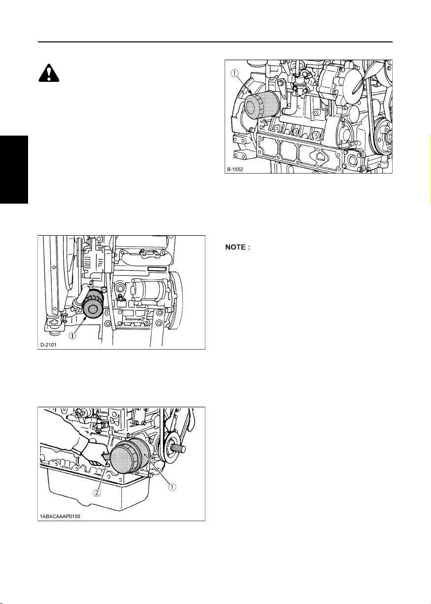
1. Replace the oil filter cartridge. (Refer to page 13)
2. Remove the old oil filter cartridge with a filter wrench.
3. Apply a film of oil to the gasket for the new cartridge.
4. Screw in the cartridge by hand. When the gasket
contacts the seal surface, tighten the cartridge
ENGLISH
enough by hand. Because, if you tighten the
cartridge with a wrench, it will be tightened too much.
[Z482-E3, Z602-E3, D722-E3, D782-E3, D902-E3,
D1005-E3, D1105-E3, D1105-TE3, D1305-E3, V1505-E3,
V1505-TE3, D1005-E3BG, D1105-E3BG, V1505-E3BG]
[V3600-E3, V3600-T-E3, V3300-E3BG, V3600-T-E3BG]
(1) Oil filter cartridge
5. After the new cartridge has been replaced, the
engine oil level normally decreases a little. Thus, run
the engine for a while and check for oil leaks through
the seal before checking the engine oil level. Add oil
if necessary.
A Wipe off any oil sticking to the machine completely.
(1) Oil filter cartridge
Remove with a filter wrench
(Tighten with your hand)
[D1503-M-E3, D1703-M-E3, D1803-M-E3, V2003-M-E3,
V2203-M-E3, V2403-M-E3, V2403-M-T-E3, D1803-M-DI-E3,
V2403-M-DI-E3]
(1) Oil filter cartridge
(2) Remove with a filter wrench
(Tighten with your hand)
Page 38

27PERIODIC SERVICE
RADIATOR
Coolant will last for one day's work if filled all the way up
before operation start. Make it a rule to check the
coolant level before every operation.
WARNING
To avoid personal injury:
A Do not stop the engine suddenly,
stop it after about 5 minutes of
unloaded idling.
A Work only after letting the engine
and radiator cool off completely
(more than 30 minutes after it has
been stopped).
A Do not remove the radiator cap
while coolant is hot. When cool to
the touch, rotate cap to the first stop
to allow excess pressure to escape.
Then remove cap completely.
If overheats should occur, steam
may gush out from the radiator or
recovery tank; Severe burns could
result.
BChecking coolant level, adding coolant
1. Remove the radiator cap, after the engine has
completely cooled, and check to see that coolant
reaches the supply port.
2. If the radiator is provided with a recovery tank, check
the coolant level of the recovery tank. When it is
between the "FULL" and "LOW" marks, the coolant
will last for one day's work.
(1) Recovery tank (A) "FULL"
3. When the coolant level drops due to evaporation,
add water only up to the full level.
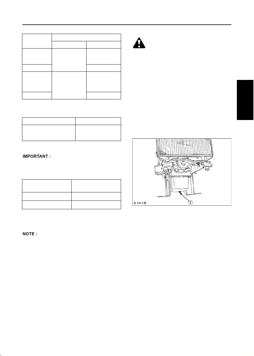
4. Check to see that two drain cocks; one is at the
crankcase side and the other is at the lower part of
the radiator as figures below.
[Z482-E3, Z602-E3, D722-E3, D782-E3, D902-E3]
(B) "LOW"
ENGLISH
(1) Radiator pressure ca p
(1) Coolant drain cock
Page 39

28 PERIODIC SERVICE
[D1005-E3, D1105-E3, D1105-TE3, D1305-E3, V1505-E3,
V1505-TE3, D1005-E3BG, D1105-E3BG, V1505-E3BG]
ENGLISH
(1) Coolant drain cock
[D1503-M-E3, D1703-M-E3, D1803-M-E3, V2003-M-E3,
V2203-M-E3, V2403-M-E3, V2403-M-T-E3, D1803-M-DI-E3,
V2403-M-DI-E3]
(1) Coolant drain cock
Page 40

29PERIODIC SERVICE
[V3600-E3, V3600-T-E3, V3300-E3BG, V3600-T-E3BG]
(1) Coolant drain cock
A If the radiator cap has to be removed, follow the
caution and securely retighten the cap.
A If coolant should be leak, consult your local KUBOTA
dealer.
A Make sure that muddy or sea water does not enter
the radiator.
A Use clean, fresh water and 50% anti-freeze to fill the
recovery tank.
A Do not refill recovery tank with coolant over the
"FULL" level mark.
A Be sure to close the radiator cap securely. If the cap
is loose or improperly closed, coolant may leak out
and decrease quickly.
BChanging coolant
1. To drain coolant, always open both drain cocks and
simultaneously open the radiator cap as well. With
the radiator cap kept closed, a complete drain of
water is impossible.
2. Remove the overflow pipe of the radiator pressure
cap to drain the recovery tank.
3. Prescribed coolant volume (U.S.gallons)
Models Quantity
Z482-E3, Z602-E3 2.8 L (0.74 U.S.gals.)
D722-E3, D782-E3,
D902-E3
D1005-E3, D1105-E3,
D1105-TE3, D1305-E3,
D1005-E3BG, D1105-E3BG
V1505-E3, V1505-E3BG 4.0 L (1.06 U.S.gals.)
V1505-TE3 5.0 L (1.32 U.S.gals.)
D1503-M-E3
D1703-M-E3
D1803-M-E3
D1803-M-DI-E3
V2003-M-E3
V2203-M-E3
V2403-M-E3
V2403-M-T-E3
V2403-M-DI-E3
V3600-E3, V3600-T-E3,
V3300-E3BG, V3600-T-E3BG
A Coolant quantities shown are for standard radiators.
4. An improperly tightened radiator cap or a gap
between the cap and the seat quickens loss of
coolant.
5. Coolant (Radiator cleaner and anti-freeze)
All seasons: Pure water and anti-freeze (See "Antifreeze" in "RADIATOR" section.)
3.1 L (0.82 U.S.gals.)
3.1 L (0.82 U.S.gals.)
5.5 L (1.45 U.S.gals.)
5.8 L (1.53 U.S.gals.)
8.1 L (2.14 U.S.gals.)
8.4 L (2.22 U.S.gals.)
9.0 L (2.38 U.S.gals.)
ENGLISH
Page 41

30 PERIODIC SERVICE
BRemedies for quick decrease of coolant
1. Check any dust and dirt between the radiator fins
and tube. If any, remove them from the fins and the
tube.
2. Check the tightness of the fan belt. If loose, tighten it
securely.
3. Check the internal blockage in the radiator hose. If
scale forms in the hose, clean with the scale inhibitor
or its equivalent.
BChecking radiator hoses and clamp
CAUTION
To avoid personal injury:
A Be sure to check radiator hoses and
ENGLISH
hose clamps periodically. If radiator
hose is damaged or coolant leaks,
overheats or severe burns could
occur.
Check to see if radiator hoses are properly fixed every
200 hours of operation or 6 months, whichever comes
first.
1. If hose clamps are loose or water leaks, tighten hose
clamp securely.
2. Replace hoses and tighten hose clamps securely, if
radiator hoses are swollen, hardened or cracked.
Replace hoses and hose clamps every 2 years or
earlier, if checked and found that hoses are swollen,
hardened or cracked.
[V3600-E3, V3600-T-E3, V3300-E3BG, V3600-T-E3BG
only]
Check to see if radiator hoses are properly fixed every
250 hours of operation or 6 months, whichever comes
first.
1. If clamp bands are loose or water leaks, tighten
clamp bands securely.
2. Replace hoses and tighten clamp bands securely, if
radiator hoses are swollen, hardened or cracked.
Replace hoses and clamp bands every 2 years or
earlier, if checked and found that hoses are swollen,
hardened or cracked.
BPrecaution at overheating
The event that the coolant temperature is nearly or more
than the boiling point is called "OVERHEATING".
While running, make the following checks to see that all
parts are working correctly. If anything is unusual,
inspect it, referring to the relevant description in
"MAINTENANCE" and "PERIODIC SERVICE"
section.
C Coolant
If the coolant temperature warning lamp lights up or if
steam or coolant does not stop squirting from the
radiator overflow pipe, turn off the load and keep the
engine idling (COOLING-DOWN) for at least 5
minutes to let it cool down gradually. Then stop the
engine and take the following inspection and servicing.
1. Check to see if the coolant runs short or if there is
any coolant leak;
2. Check to see if there is any obstacle around the
cooling air inlet or outlet;
3. Check to see if there is any dirt or dust between
radiator fins and tube;
4. Check to see if the fan belt is too loose; and
5. Check to see if radiator water pipe is clogged.
BCleaning radiator core (outside)
If dust is between the fin and tube, wash it away with
running water.
A Do not clean radiator with firm tools such as spatulas
or screwdrivers. They may damage specified fin or
tube. It can cause coolant leaks or decrease cooling
performance.
Page 42

31PERIODIC SERVICE
BAnti-freeze
CAUTION
To avoid personal injury:
A When using anti-freeze, put on
some protection such as rubber
gloves (Anti-freeze contains
poison.).
A If should drink anti-freeze, throw up
at once and take medical attention.
A When anti-freeze comes in contact
with the skin or clothing, wash it off
immediately.
A Do not mix different types of anti-
freeze. The mixture can produce
chemical reaction causing harmful
substances.
A Anti-freeze is extremely flammable
and explosive under certain
conditions. Keep fire and children
away from anti-freeze.
A When draining fluids from the
engine, place some container
underneath the engine body.
A Do not pour waste onto the
grounds, down a drain, or into any
water source.
A Also, observe the relevant
environmental protection regulations
when disposing of anti-freeze.
Always use a 50/50 mix of long-life coolant and clean
soft water in KUBOTA engines.
Contact KUBOTA concerning coolant for extreme
conditions.
1. Long-life coolant (hereafter LLC) comes in several
types. Use ethylene glycol (EG) type for this engine.
2. Before employing LLC-mixed cooling water, flush
the radiator with fresh water. Repeat this procedure
2 or 3 times to clean up the radiator and engine block
from inside.
3. Mixing the LLC
Premix 50% LLC with 50% clean soft water. When
mixing, stir it up well, and then fill into the radiator.
4. The procedure for the mixing of water and antifreeze differs according to the make of the antifreeze. Refer to SAE J1034 standard, more
specifically also to SAE J814c.
Vol %
Anti-freeze
50 -37 -34 108 226
*At 1.013 x 10
(atmospheric). A higher boiling point is obtained by
using a radiator pressure cap which permits the
development of pressure within the cooling system.
5. Adding the LLC
(1) Add only water if the coolant level reduces in the
cooling system by evaporation.
(2) If there is a coolant leak, add the LLC of the same
manufacturer and type in the same coolant percent-
age.
*Never add any long-life coolant of different manufacturer. (Different brands may have different additive components, and the engine may fail to perform
as specified.)
6. When the LLC is mixed, do not employ any radiator
cleaning agent. The LLC contains anti-corrosive
agent. If mixed with the cleaning agent, sludge may
build up, adversely affecting the engine parts.
7. Kubota's genuine long-life coolant has a service life
of 2 years. Be sure to change the coolant every 2
years.
A The above data represent industry standards that
necessitate a minimum glycol content in the
concentrated anti-freeze.
Freezing Point Boiling Point *
°C °F °C °F
5
Pa (760 mmHg) pressure
ENGLISH
Page 43
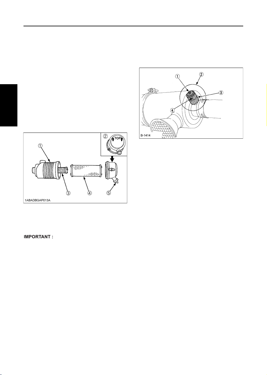
32 PERIODIC SERVICE
AIR CLEANER
[Z482-E3, Z602-E3, D722-E3, D782-E3, D902-E3,
D1005-E3, D1105-E3, D1105-TE3, D1305-E3, V1505-E3,
V1505-TE3, D1005-E3BG, D1105-E3BG, V1505-E3BG]
Since the air cleaner employed on this engine is a dry
type, never apply oil to it.
1. Open the evacuator valve once a week under
ordinary conditions - or daily when used in a dusty
place. This will get rid of large particles of dust and
dirt.
2. Wipe the inside air cleaner clean with cloth if it is dirty
or wet.
3. Avoid touching the element except when cleaning.
4. When dry dust adheres to the element, blow
compressed air from the inside turning the element.
Pressure of compressed air must be under 205 kPa
(2.1 kgf/cm
ENGLISH
5. Replace the element every year or every 6
cleanings.
(1) Air cleaner body
(2) Cover
(3) Secondary element
(4) Primary element
(5) Evacuator valve
2
, 30 psi).
BDust indicator (optional)
If the red signal on the dust indicator attached to the air
cleaner is visible, the air cleaner has reached the
service level.
Clean the element immediately, and reset the signal
with the "RESET" button.
(1) "RESET" button
(2) Dust indicator
(3) Service level
(4) Signal
A Make sure the wing bolt for the element is tight
enough. If it is loose, dust and dirt may be sucked in,
wearing down the cylinder liner and piston ring
earlier and thereby resulting in poor power output.
A Do not overservice the air cleaner element.
Overservicing may cause dirt to enter the engine
causing premature wear. Use the dust indicator as a
guide on when to service.
BEvacuator valve
Open the evacuator valve once a week under ordinary
conditions - or daily when used in a dusty place - to get
rid of large particles of dust and dirt.
Page 44

[D1503-M-E3, D1703-M-E3, D1803-M-E3, V2003-M-E3,
V2203-M-E3, V2403-M-E3, V2403-M-T-E3, D1803-M-DI-E3,
V2403-M-DI-E3]
Since the air cleaner employed on this engine is a dry
type, never apply oil to it.
1. Open the evacuator valve once a week under
ordinary conditions - or daily when used in a dusty
place. This will get rid of large particles of dust and
dirt.
2. Wipe the inside air cleaner clean with cloth if it is dirty
or wet.
3. Avoid touching the primary element except when
cleaning.
4. When dry dust adheres to the primary element, blow
compressed air from the inside turning the element.
Pressure of compressed air must be under 205 kPa
(2.1 kgf/cm
5. When carbon or oil adheres to the primary element,
soak the element in detergent for 30 minutes, then
wash it several times in water, rinse with clean water
and dry it naturally.
6. After the primary element is fully dried, inspect inside
of the element with a light and check if it is damaged
or not.
7. Replace the primary element every year or every 6
cleanings. If the primary element is stained heavily,
replace it soon. At this time, replace the secondary
element too.
8. The secondary element should be removed only if it
is to be replaced.
9. To protect the engine, do not remove the secondary
element in servicing the primary element.
2
, 30 psi).
33PERIODIC SERVICE
A Make sure hooking clip for cover for the element is
tight enough. If it is loose, dust and dirt may be
sucked in, wearing down the cylinder liner and piston
ring earlier, and thereby resulting in poor power
output.
A Do not overservice the air cleaner element.
Overservicing may cause dirt to enter the engine
causing premature wear. Use the dust indicator as a
guide on when to service.
A Be sure to refit the cover with the arrow (on the
rear of the cover) upright. If the cover is improperly
fitted, the evacuator valve will not function and dust
will adhere to the element.
BEvacuator valve
Open the evacuator valve once a week under ordinary
conditions - or daily when used in a dusty place - to get
rid of large particles of dust and dirt.
BDust indicator (optional)
If the red signal on the dust indicator attached to the air
cleaner is visible, the air cleaner has reached the
service level.
Clean the element immediately, and reset the signal
with the "RESET" button.
ENGLISH
(1) Air cleaner body
(2) Cover
(3) Secondary element
(4) Primary element
(5) Evacuator valve
(1) "RESET" button
(2) Dust indicator
(3) Service level
(4) Signal
Page 45

34 PERIODIC SERVICE
[V3600-E3, V3600-T-E3, V3300-E3BG, V3600-T-E3BG]
Since the air cleaner employed on this engine is a dry
type, never apply oil to it.
1. Open the evacuator valve once a week under
ordinary conditions - or daily when used in a dusty
place. This will get rid of large particles of dust and
dirt.
2. Wipe the inside air cleaner clean with cloth if it is dirty
or wet.
3. Avoid touching the primary element except when
cleaning.
4. When dry dust adheres to the element, blow
compressed air from the inside turning the element.
Pressure of compressed air must be under 205 kPa
(2.1 kgf/cm
5. Replace the primary element every year or every 6
cleanings. If the primary element is stained heavily,
ENGLISH
replace it soon. At this time, replace the secondary
element too.
6. The secondary element should be removed only if it
is to be replaced.
7. To protect the engine, do not remove the secondary
2
, 30 psi).
element in servicing the primary element.
BCleaning primary air filter element
1. To clean the element, use clean dry compressed air
on the inside of the element.
Air pressure at the nozzle must not exceed 205 kPa
(2.1 kgf/cm
Maintain reasonable distance between the nozzle
and the filter.
2. To wash the elements, use Donaldson ND-1500
Filter Cleaner, or its equivalent, which is especially
effective on oily and soot-laden filters.
Follow instructions that are supplied with the filter
cleaner.
2
, 30 psi).
BEvacuator valve
Open the evacuator valve once a week under ordinary
conditions - or daily when used in a dusty place - to get
rid of large particles of dust and dirt.
BFor the air cleaner with a dust cup
(optional)
Remove and clean out the dust cup before it becomes
half full with dust; usually once a week, or even every
day if the working surroundings are dusty.
Install the air cleaner dust cup with "TOP" indicated on
the rear of the cup in the up position. (However, it may
be installed in either direction when the cover is placed
at the lower part.)
A If the dust cup is mounted incorrectly, dust or dirt
does not collect in the cup, and direct attachments of
the dust to the element will cause its lifetime to
shorten to a great extent.
(1) Air cleaner body
(2) Cover
(3) Secondary element
(4) Primary element
(5) Evacuator valve
A Make sure the hooking clip for the element is tight
enough. If it is loose, dust and dirt may be sucked in,
wearing down the cylinder liner and piston ring
earlier and thereby resulting in poor power output.
A Do not overservice the air cleaner element.
Overservicing may cause dirt to enter the engine
causing premature wear. Use the dust indicator as a
guide on when to service.
(1) Air cleaner body
(2) Secondary element
(3) Primary element
(4) Dust cup
(5) "Top" mark
Page 46

35PERIODIC SERVICE
BDust indicator (optional)
If the red signal on the dust indicator attached to the air
cleaner is visible, the air cleaner has reached the
service level.
Clean the element immediately, and reset the signal
with the "RESET" button.
(1) "RESET" button
(2) Dust indicator
(3) Service level
(4) Signal
BATTERY
CAUTION
To avoid personal injury:
A Be careful not to let the battery
electrolyte contact your body or
clothing.
A Wear eye protection and rubber
gloves, since the diluted sulfuric
acid solution burns skin and eats
holes in clothing. Should this occur,
immediately wash it off with running
water and get medical attention.
Mishandling of the battery shortens the service life and
adds to maintenance costs. Obtain the maximum
performance and the longest life of the battery by
handling properly and with care.
Engine starting will be more difficult, if the battery
charge is low. Be careful to recharge it at an early
occasion before it is too late.
BBattery charging
DANGER
The battery comes in two types:
refillable and non-refillable.
A For using the refillable type battery,
follow the instructions below.
Do not use or charge the battery if
its fluid level stands below the
LOWER (lower limit level) mark.
Otherwise, the battery component
parts may deteriorate earlier than
expected, which may shorten the
battery's service life or cause an
explosion.
Immediately, add distilled water
until the battery's fluid level is
between the UPPER and LOWER
levels.
ENGLISH
Page 47

36 PERIODIC SERVICE
CAUTION
To avoid personal injury:
A When the battery is being activated,
hydrogen and oxygen gases in the
battery are extremely explosive.
Keep open sparks and flames away
from the battery at all times,
especially when charging the
battery.
A When charging the battery, remove
the battery vent plugs.
A When disconnecting the cable from
ENGLISH
the battery, start with the negative
terminal, and when connecting
them, start with the positive terminal
first.
A DO NOT check the battery charge by
placing a metal object across the
terminals. Use a voltmeter or
hydrometer.
1. Make sure each electrolyte level is to the bottom of
vent wells, if necessary, add only distilled water in a
well-ventilated place.
(1) Thick cable red(+)
(2) Battery case
(3) Earth cable black(-)
(1) Battery electrolyte level (A) "TOO LOW"
2. To slow charge the battery, connect the charger
positive terminal to the battery positive terminal, and
the negative to the negative, then recharge in the
standard fashion.
3. Quick recharging charges the battery at a high rate
in a short time. This is only for emergencies.
4. Recharge the battery as early as possible, or battery
life will be extremely shortened.
5. When exchanging an old battery for a new one, use
battery of equal specification shown in
"SPECIFICATIONS" section.
(B) "PROPER"
(C) "TOO HIGH"
(1) Plug (A) "HIGHEST LEVEL"
A Connect the charger positive terminal to the battery
positive terminal, and negative to the negative.
A When disconnecting the cable from the battery, start
with the negative terminal first.
When connecting the cable to the battery, start with
the positive terminal first.
If reversed, the contact of tools on the battery may
cause a short.
(B) "LOWEST LEVEL"
BDirection for long term storage
1. When storing the engine for long periods of time,
remove the battery, adjust the electrolyte to the
proper level, and store in a dry and dark place.
2. The battery naturally discharges while it is stored.
Recharge it once a month in summer, and every 2
months in winter.
Page 48

37PERIODIC SERVICE
ELECTRIC WIRING
CAUTION
To avoid personal injury:
CShorting of electric cable or wiring
may cause a fire.
ACheck to see if electric cables and
wiring are swollen, hardened or
cracked.
AKeep dust and water away from all
power connections.
Loose wiring terminal parts, make
bad connections. Be sure to repair
them before starting the engine.
Damaged wiring reduces the capacity of electrical parts.
Change or repair damaged wiring immediately.
FAN BELT
BAdjusting fan belt tension
CAUTION
To avoid personal injury:
A Be sure to stop the engine and
remove the key before checking the
belt tension.
A Be sure to reinstall the detached
safety shield after maintenance or
checking.
Proper fan belt
tension
[V3600-E3, V3600-T-E3, V3300-E3BG, V3600-T-E3BG]
Proper fan belt
tension
A deflection of between 7 to 9 mm
(0.28 to 0.35 in.) when the belt is
pressed in the middle of the span.
A deflection of between 10 to 12 mm
(0.39 to 0.47 in.) when the belt is
pressed in the middle of the span.
[Z482-E3, Z602-E3, D722-E3, D782-E3, D902-E3,
D1005-E3, D1105-E3, D1105-TE3, D1305-E3, V1505-E3,
V1505-TE3, D1005-E3BG, D1105-E3BG, V1505-E3BG]
(1) Fan belt
(2) Bolt and nut
[D1503-M-E3, D1703-M-E3, D1803-M-E3, V2003-M-E3,
V2203-M-E3, V2403-M-E3, V2403-M-T-E3, D1803-M-DI-E3,
V2403-M-DI-E3]
(1) Fan belt
(2) Bolt and nut
[V3600-E3, V3600-T-E3, V3300-E3BG, V3600-T-E3BG]
(A) 7 to 9 mm (0.28 to 0.35 in.)
(under load of 10 kgf (22.1 lbs))
(A) 7 to 9 mm (0.28 to 0.35 in.)
(unde r loa d of 10 kgf ( 22.1 lbs) )
ENGLISH
1. Stop the engine and remove the key.
2. Apply moderate thumb pressure to belt between the
pulleys.
3. If tension is incorrect, loosen the alternator mounting
bolts and, using a lever placed between the
alternator and the engine block, pull the alternator
out until the deflection of the belt falls within
acceptable limits.
4. Replace fan belt if it is damaged.
A If belt is loosen or damaged and the fan is damaged,
it could result in overheats or insufficient charging.
Correct or replace belt.
(1) Fan belt
(2) Bolt and nut
(A) 10 to 12 mm (0.39 to 0.47 in.)
(under load of 6~7 kgf (13.2~15.4
lbs))
Page 49

38 CARRIAGE AND STORAGE
CARRIAGE AND STORAGE
CARRIAGE
CAUTION
To avoid personal injury:
A Fix the engine securely not to fall
during operation.
A Do not stand near or under the
engine while carrying it.
A The engine is heavy. In handling it,
ENGLISH
be very alert not to get your hands
and body caught in.
1. Use carrier such as crane when carrying the engine,
or hurt your waist and yourself. Support the engine
securely with rope not to fall while carrying it.
2. When lifting the engine, put the hook securely to
metal fittings attached to the engine. Use strong
hook and fittings enough to hang the engine.
STORAGE
CAUTION
To avoid personal injury:
A Do not clean the machine with
engine running.
A To avoid the danger of exhaust fume
poisoning, do not operate the
engine in a closed building without
proper ventilation.
A When storing the engine just after
running, let the engine cool off.
Before storing the engine for more than a few months,
remove any dirt on the machine, and:
1. Drain the coolant in the radiator. Open the cock at
the bottom of the radiator, and remove the pressure
cap to drain water completely. Leave the cock open.
Hang a note written "No water" on the pressure cap.
Since water may freeze when the temperature drops
below 0°C (32°F), it is very important that no water is
left in the machine.
2. Remove dirty engine oil, fill with new oil and run the
engine for about 5 minutes to let the oil penetrate to
all the parts.
3. Check all the bolts and nuts, and tighten if
necessary.
4. Remove the battery from the engine, adjust the
electrolyte level, and recharge it. Store the battery in
a dry and dark place.
5. When the engine is not used for a long period of
time, run it for about 5 minutes under no load every
2 to 3 months to keep it free from rust. If the engine
is stored without any running, moisture in the air may
condense into dew over the sliding parts of the
engine, resulting in rust there.
6. If you forget to run the engine for longer than 5 to 6
months, apply enough engine oil to the valve guide
and valve stem seal and make sure the valve works
smoothly before starting the engine.
7. Store the engine in a flat place and remove the key
from engine.
8. Do not store the engine in a place where has
flammable materials such as dry grass or straw.
9. When covering the engine for storage, let engine
and muffler cool off completely.
10.Operate the engine after checking and repairing
damaged wirings or pipes, and clearing flammable
materials carried by mouse.
Page 50

TROUBLESHOOTING
If the engine does not function properly, use the following chart to identify and correct the cause.
When it is difficult to start the engine When output is insufficient
Cause Countermeasures
Fuel is thick and
doesn't flow.
Air or water mixed
in fuel system
Valve clearance is
not as specified.
Leaking valves * Grind valve.
Fuel injection
timing is not as
specified.
Engine oil
becomes thick in
cold weather and
engine cranks
slow.
Low compression
Battery is
discharged and
the engine will not
crank.
*
Check the fuel tank and fuel filter.
*
Remove water, dirt and other
impurities.
*
As all fuel will be filtered by the filter,
if there should be water or other
foreign matters on the filter, clean the
filter with kerosene.
*
If air is in the fuel filter or injection
lines, the fuel pump will not work
properly.
*
To attain proper fuel injection
pressure, check carefully for
loosened fuel line coupling, loose cap
nut, etc.
*
Loosen joint bolt stop fuel filter and air
vent screws of fuel injection pump to
eliminate all the air in the fuel system.
* Adjust valve clearance when the
engine is cold.
* Check injection timing.
* Change grade of oil according to the
weather (temperature).
* Bad valve or excessive wear of rings,
pistons and liners cause insufficient
compression. Replace with new
parts.
**Charge battery.
In winter, always remove battery from
machine, charge fully and keep
indoors. Install in machine at time of
use.
Cause Countermeasures
Compression is
insufficient.
Leaking valves
Fuel is insufficient.
Overheating of
moving parts
Valve clearance
is not as
specified.
Air cleaner is
dirty
Fuel injection
pressure is not
as specified.
Injection pump
wear
**Bad valve and excessive wear of rings,
pistons and liners cause insufficient
compression. Replace with new parts.
Grind valves.
* Check fuel system.
*
Check lubricating oil system.
*
Check to see if lubricating oil filter is
working properly.
*
Filter element deposited with impurities
would cause poor lubrication. Change
element.
*
Check the clearance of bearing are
within factory specs.
*
Check injection timing.
*
Adjust timing
* Adjust to proper valve clearance when
the engine is cold.
* Clean the element every 100 hours of
operation.
* Check injection pressure.
**Do not use poor quality fuel as it will
cause wear of the pump. Only use No.
2-D diesel fuel. (See "FUEL" in
"PERIODIC SERVICE" Section.)
Check the fuel injection pump element
and delivery valve assembly and
replace as necessary.
39TROUBLESHOOTING
ENGLISH
A If the cause of trouble can not be found, contact your KUBOTA dealer.
Page 51

40 TROUBLESHOOTING
When engine suddenly stops
Cause Countermeasures
Lack of fuel
Bad nozzle
Moving parts are
overheated due to
shortage of
lubrication oil or
improper
lubrication.
When color of exhaust is especially bad
ENGLISH
Cause Countermeasures
Fuel governing
device bad
Fuel is of
extremely poor
quality.
Nozzle is bad.
Combustion is
incomplete.
**Check the fuel tank and refill the fuel,
if necessary.
Also check the fuel system for air or
leaks.
* If necessary, replace with a new
nozzle.
*
Check amount of engine oil with oil
level gauge.
*
Check lubricating oil system.
*
At every 2 times of oil change, oil filter
cartridge should be replaced.
*
Check to see if the engine bearing
clearances is within factory specs.
* Contact dealer for repairs.
* Select good quality fuel.
Use No. 2-D diesel fuel only.
* If necessary, replace with new
nozzle.
* Cause is poor atomization, improper
injection timing, etc. Because of
trouble in injection system or in poor
valve adjustment, or compression
leakage, poor compression, etc.
Check for the cause.
When engine must be stopped immediately
Cause Countermeasures
Engine revolution
suddenly
decreases or
increases.
Unusual sound is
heard suddenly.
Color of exhaust
suddenly turns
dark.
Bearing parts are
overheated.
Oil lamp lights up
during operation.
* Check the adjustments, injection
timing and the fuel system.
* Check all moving parts carefully.
* Check the fuel injection system,
especially the fuel injection nozzle.
* Check the lubricating system.
*
Check the lubricating system.
*
Check, if the engine bearing
clearances are within factory specs.
*
Check the function of the relieve
valve in the lubricating system.
*
Check pressure switch.
*
Check filter base gasket.
When engine overheats
Cause Countermeasures
Engine oil
insufficient
Fan belt broken or
elongated
Coolant insufficient * Replenish coolant.
Excessive
concentration of
antifreeze
Radiator net or
radiator fin clogged
with dust
Inside of radiator
or coolant flow
route corroded
Fan or radiator or
radiator cap
defective
Thermostat
defective
Temperature
gauge or sensor
defective
Overload running * Reduce load.
Head gasket
defective or water
leakage
Incorrect injection
timing
Unsuitable fuel
used
* Check oil level. Replenish oil as
required.
* Change belt or adjust belt tension.
* Add water only or change to coolant
with the specified mixing ratio.
* Clean net or fin carefully.
* Clean or replace radiator and parts.
* Replace defective parts.
* Check thermostat and replace if
necessary.
*
Check temperature with thermometer
and replace if necessary.
* Replace parts.
* Adjust to proper timing.
* Use the specified fuel.
Page 52

SPECIFICATIONS
Model Z482-E3 Z602-E3
Type Vertical, water-cooled, 4-cycle diesel engine
Number of cylinders 2
Bore and stroke mm (in.) 67 × 68 (2.64 × 2.68) 72 × 73.6 (2.83 × 2.90)
Total displacement L (cu.in.) 0.479 (29.23) 0.599 (36.55)
Combustion chamber Spherical Type (E-TVCS)
SAE NET Intermittent kW / rpm
H.P. ( SAEJ 1349 ) (HP / rpm)
SAE NET Continuous kW / rpm
H.P. ( SAEJ 1349 ) (HP / rpm)
Maximum bare speed rpm 3800 3850
Minimum bare idling speed rpm 900 ~ 1000
Order of firing 1-2
Direction of rotation Counter-clockwise (viewed from flywheel side)
Injection pump Bosch MD Type Mini Pump
Injection pressure 13.73 Mpa, 1991 psi (140 kgf/cm
Injection timing (Before T.D.C.) 0.366 rad (20°) 0.35 rad (20°)
Compression ratio 23.5 : 1 24 : 1
Fuel Diesel Fuel No.2-D
Lubricant
(API classification)
Dimension mm (in.)
(length × width × height)
Dry weight
(BB Spec.) kg (l bs.)
Starting system Cell starter (with glow plug)
Starting motor 12 V, 0.8 kW 12 V, 1.0 kW
Charging generator 12 V, 150 W 12 V, 480 W
Recommended battery capacity
(5Hr capacity)
9.3/3600
(12.5/3600)
8.1/3600
(10.8/3600)
above CF grade
351 × 389 × 520
(13.82 × 15.31 × 20.47)
53.1
(117.1)
12 V, 28 AH, equivalent 12 V, 36 AH, equivalent
11.6/3600
(15.6/3600)
10.1/3600
(13.5/3600)
2
)
385 × 421 × 544
(15.16 × 16.57 × 21.42)
57.0
(125.7)
41SPECIFICATIONS
ENGLISH
A Specifications are subject to change without notice.
A The battery capacity is indicated in 5-hour ratio.
Page 53

42 SPECIFICATIONS
Model D722-E3 D782-E3 D902-E3
Type Vertical, water-cooled, 4-cycle diesel engine
Number of cylinders 3
Bore and stroke mm (in.)
67 × 68
(2.64 × 2.68)
67 × 73.6
(2.64 × 2.90)
(2.83 × 2.90)
Total displacement L (cu.in.) 0.719 (43.88) 0.778 (47.46) 0.898 (54.80)
Combustion chamber Spherical Type (E-TVCS)
SAE NET Intermittent kW / rpm
H.P. ( SAEJ 1349 ) (HP / rpm)
ENGLISH
SAE NET Continuous kW / rpm
H.P. ( SAEJ 1349 ) (HP / rpm)
14.0/3600
(18.8/3600)
12.2/3600
(16.3/3600)
13.5/3200
(18.1/3200)
11.7/3200
(15.7/3200)
17.5/3600
(23.5/3600)
15.2/3600
(20.4/3600)
Maximum bare speed rpm 3800 3450 3850
Minimum bare idling speed rpm 900 ~ 1000
Order of firing 1-2-3
Direction of rotation Counter-clockwise (viewed from flywheel side)
Injection pump Bosch MD Type Mini Pump
Injection pressure 13.73 Mpa, 1991 psi (140 kgf/cm
Injection timing (Before T.D.C.) 0.366 rad (20°) 0.35 rad (20°)
Compression ratio 23.5 : 1 24 : 1
Fuel Diesel Fuel No.2-D
Lubricant
(API classification)
Dimension mm (in.)
(length × width × height)
Dry weight
(BB Spec.) kg (l bs.)
426 × 389 × 520
(16.77 × 15.31 × 20.47)
63.1
(139.1)
above CF grade
467 × 421 × 544
(18.39 × 16.57 ×
63.5
(140.0)
Starting system Cell starter (with glow plug)
Starting motor 12 V, 0.8 kW 12 V, 1.2 kW
Charging generator 12 V, 150 W 12 V, 480 kW
Recommended battery capacity
(5Hr capacity)
12 V, 36 AH, equivalent
12 V, 52 AH,
equivalent
72 × 73.6
2
)
21.42)
72.0
(158.7)
A Specifications are subject to change without notice.
A The battery capacity is indicated in 5-hour ratio.
Page 54

Model D1005-E3 D1105-E3
Type Vertical, water-cooled, 4-cycle diesel engine
Number of cylinders 3
Bore and stroke mm (in.) 76 × 73.6 (2.99 × 2.90) 78 × 78.4 (3.07 × 3.09)
Total displacement L (cu.in.) 1.001 (61.08) 1.123 (68.53)
Combustion chamber Spherical Type (E-TVCS)
SAE NET Intermittent kW / rpm
H.P. ( SAEJ 1349 ) (HP / rpm)
SAE NET Continuous kW / rpm
H.P. ( SAEJ 1349 ) (HP / rpm)
16.8/3000
(22.5/3000)
14.6/3000
(19.6/3000)
17.5/3600
(23.5/3600)
15.2/3600
(20.4/3600)
17.8/3000
(23.9/3000)
15.5/3000
(20.8/3000)
Maximum bare speed rpm 3200 3800 3200
Minimum bare idling speed rpm 850 ~ 950
Order of firing 1-2-3
Direction of rotation Counter-clockwise (viewed from flywheel side)
Injection pump Bosch MD Type Mini Pump
Injection pressure 13.73 Mpa (140 kgf/cm
2
, 1991 psi)
Injection timing (Before T.D.C.) 18° 21° 18°
Compression ratio 24 : 1
Fuel Diesel Fuel No.2-D (ASTM D975)
Lubricant
(API classification)
Dimension mm (in.)
(length × width × height)
Dry weight
(BB Spec.) kg (l bs.)
above CF grade
497.8 × 396.0 × 602.0
(19.60 × 15.59 × 23.7)
93
(205.0)
Starting system Cell starter (with glow plug)
Starting motor 12 V, 1.0 kW
Charging generator 12 V, 360 W
Recommended battery capacity 12 V, 65 AH, equivalent
43SPECIFICATIONS
ENGLISH
A Specifications are subject to change without notice.
Page 55

44 SPECIFICATIONS
Model D1105-TE3 D1305-E3
Type Vertical, water-cooled, 4-cycle diesel engine
Number of cylinders 3
Bore and stroke mm (in.) 78 × 78.4 (3.07 × 3.09) 78 × 88 (3.07 × 3.46)
Total displacement L (cu.in.) 1.123 (68.53) 1.261 (76.95)
Combustion chamber Spherical Type (E-TVCS)
SAE NET Intermittent kW / rpm
H.P. ( SAEJ 1349 ) (HP / rpm)
SAE NET Continuous kW / rpm
ENGLISH
H.P. ( SAEJ 1349 ) (HP / rpm)
23.5/3000
(31.5/3000)
20.4/3000
(27.3/3000)
21.0/3000
(28.2/3000)
18.2/3000
(24.4/3000)
Maximum bare speed rpm 3200
Minimum bare idling speed rpm 850 ~ 950 850 ~ 950
Order of firing 1-2-3
Direction of rotation Counter-clockwise (viewed from flywheel side)
Injection pump Bosch MD Type Mini Pump
Injection pressure 13.73 Mpa (140 kgf/cm
2
, 1991 psi)
Injection timing (Before T.D.C.) 18° 19°
Compression ratio 24 : 1
Fuel Diesel Fuel No.2-D (ASTM D975)
Lubricant
(API classification)
Dimension mm (in.)
(length × width × height)
Dry weight
(BB Spec.) kg (l bs.)
497.8 × 433.0 × 626.0
(19.60 × 17.05 × 24.65)
97
(213.8)
above CF grade
497.6 × 396.0 × 590.1
(19.59 × 15.59 × 23.2)
95
(209.4)
Starting system Cell starter (with glow plug)
Starting motor 12 V, 1.0 kW 12 V, 1.2kW
Charging generator 12 V, 360 W 12 V, 480 W
Recommended battery capacity 12 V, 65 AH, equivalent 12 V, 70 AH, equivalent
A Specifications are subject to change without notice.
Page 56

Model V1505-E3 V1505-TE3
Type Vertical, water-cooled, 4-cycle diesel engine
Number of cylinders 4
Bore and stroke mm (in.) 78 × 78.4 (3.07 × 3.09)
Total displacement L (cu.in.) 1.498 (91.41)
Combustion chamber Spherical Type (E-TVCS)
SAE NET Intermittent kW / rpm
H.P. ( SAEJ 1349 ) (HP / rpm)
SAE NET Continuous kW / rpm
H.P. ( SAEJ 1349 ) (HP / rpm)
25.0/3000
(33.5/3000)
21.7/3000
(29.1/3000)
27.5/3600
(36.9/3600)
23.9/3600
(32.0/3600)
31.3/3000
(42.0/3000)
27.2/3000
(36.5/3000)
Maximum bare speed rpm 3200 3800 3200
Minimum bare idling speed rpm 850 ~ 950 1000 ~ 1100
Order of firing 1-3-4-2
Direction of rotation Counter-clockwise (viewed from flywheel side)
Injection pump Bosch MD Type Mini Pump
Injection pressure 13.73 Mpa (140 kgf/cm
2
, 1991 psi)
Injection timing (Before T.D.C.) 18° 21° 18°
Compression ratio 24 : 1 23 : 1
Fuel Diesel Fuel No.2-D (ASTM D975)
Lubricant
(API classification)
above CF grade
591.3 × 433.0 ×
Dimension mm (in.)
(length × width × height)
591.3 × 396.0 × 607.0
(23.28 × 15.59 × 23.90)
621.0
(23.28 × 17.05 ×
24.45)
Dry weight
(BB Spec.) kg (l bs.)
110
(242.5)
114
(251.3)
Starting system Cell starter (with glow plug)
Starting motor 12 V, 1.2 kW
Charging generator 12 V, 360 W
Recommended battery capacity 12 V, 70 AH, equivalent
45SPECIFICATIONS
ENGLISH
A Specifications are subject to change without notice.
Page 57

46 SPECIFICATIONS
Model D1005-E3BG1 D1005-E3BG2
Type Vertical, water-cooled, 4-cycle diesel engine
Number of cylinders 3
Bore and stroke mm (in.) 76 × 73.6 (2.99 × 2.90)
Total displacement L (cu.in.) 1.001 (61.08)
Combustion chamber Spherical Type (E-TVCS)
SAE Continuous kW / rpm
H.P. ( SAEJ 1349 ) (HP / rpm)
SAE Stand-by kW / rpm
ENGLISH
H.P. ( SAEJ 1349 ) (HP / rpm)
8.7/1800
(11.7/1800)
9.8/1800
(13.1/1800)
7.2/1500
(9.7/1500)
8.2/1500
(11.0/1500)
Maximum bare speed rpm 1890 1575
Order of firing 1-2-3
Direction of rotation Counter-clockwise (viewed from flywheel side)
Injection pump Bosch MD Type Mini Pump
Injection pressure 140 kgf/cm
2
(13.73 MPa, 1991 psi)
Injection timing (Before T.D.C.) 16.5° 15.5°
Compression ratio 24 : 1
Fuel Diesel Fuel No.2-D (ASTM D975)
Lubricant
(API classification)
Dimension mm (in.)
(length × width × height)
Dry weight
(BB Spec.) kg (l bs.)
above CF grade
551.3 × 396 × 602
(21.7 × 15.6 × 23.7)
110
(242.5)
Starting system Cell starter (with glow plug)
Starting motor 12 V, 1.0 kW
Charging generator 12 V, 360 W
Recommended battery capacity 12 V, 65 AH, equivalent
A Model EBG1 is 1800rpm for 60Hz, EBG2 is 1500rpm for 50Hz.
A Flywheel type is SAE clutch No. 6-1/2 or its equivalent.
A Flywheel housing type is SAE No. 5 or its equivalent.
A Governor drop is within 5%.
A Continuous will operate at the stated rating continuously and have a 10% overload capability for one hour in 12
hours.
A Standby will operate at the stated full rating for one hour in 12 hours. No overload capacity is specified for this rating.
A Specifications are subject to change without notice.
Page 58
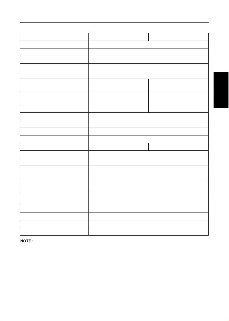
Model D1105-E3BG1 D1105-E3BG2
Type Vertical, water-cooled, 4-cycle diesel engine
Number of cylinders 3
Bore and stroke mm (in.) 78 × 78.4 (3.07 × 3.09)
Total displacement L (cu.in.) 1.123 (68.53)
Combustion chamber Spherical Type (E-TVCS)
SAE Continuous kW / rpm
H.P. ( SAEJ 1349 ) (HP / rpm)
SAE Stand-by kW / rpm
H.P. ( SAEJ 1349 ) (HP / rpm)
10.1/1800
(13.6/1800)
11.5/1800
(15.4/1800)
8.4/1500
(11.3/1500)
9.5/1500
(12.7/1500)
Maximum bare speed rpm 1890 1575
Order of firing 1-2-3
Direction of rotation Counter-clockwise (viewed from flywheel side)
Injection pump Bosch MD Type Mini Pump
Injection pressure 140 kgf/cm
2
(13.73 MPa, 1991 psi)
Injection timing (Before T.D.C.) 16.5° 15.5°
Compression ratio 24 : 1
Fuel Diesel Fuel No.2-D (ASTM D975)
Lubricant
(API classification)
Dimension mm (in.)
(length × width × height)
Dry weight
(BB Spec.) kg (l bs.)
above CF grade
551.3 × 396 × 602
(21.7 × 15.6 × 23.7)
110
(242.5)
Starting system Cell starter (with glow plug)
Starting motor 12 V, 1.0 kW
Charging generator 12 V, 360 W
Recommended battery capacity 12 V, 65 AH, equivalent
47SPECIFICATIONS
ENGLISH
A Model EBG1 is 1800rpm for 60Hz, EBG2 is 1500rpm for 50Hz.
A Flywheel type is SAE clutch No. 6-1/2 or its equivalent.
A Flywheel housing type is SAE No. 5 or its equivalent.
A Governor drop is within 5%.
A Continuous will operate at the stated rating continuously and have a 10% overload capability for one hour in 12
hours.
A Standby will operate at the stated full rating for one hour in 12 hours. No overload capacity is specified for this rating.
A Specifications are subject to change without notice.
Page 59

48 SPECIFICATIONS
Model V1505-E3BG1 V1505-E3BG2
Type Vertical, water-cooled, 4-cycle diesel engine
Number of cylinders 4
Bore and stroke mm (in.) 78 × 78.4 (3.07 × 3.09)
Total displacement L (cu.in.) 1.498 (91.41)
Combustion chamber Spherical Type (E-TVCS)
SAE Continuous kW / rpm
H.P. ( SAEJ 1349 ) (HP / rpm)
SAE Stand-by kW / rpm
ENGLISH
H.P. ( SAEJ 1349 ) (HP / rpm)
13.4/1800
(18.0/1800)
15.1/1800
(20.2/1800)
11.1/1500
(14.9/1500)
12.5/1500
(16.8/1500)
Maximum bare speed rpm 1890 1575
Order of firing 1-3-4-2
Direction of rotation Counter-clockwise (viewed from flywheel side)
Injection pump Bosch MD Type Mini Pump
Injection pressure 140 kgf/cm
2
(13.73 MPa, 1991 psi)
Injection timing (Before T.D.C.) -16.0 -15.0
Compression ratio 24 : 1
Fuel Diesel Fuel No.2-D (ASTM D975)
Lubricant
(API classification)
Dimension mm (in.)
(length × width × height)
Dry weight
(BB Spec.) kg (l bs.)
above CF grade
634.3 × 396 × 602
(25.0 × 15.6 × 23.7)
127
(280.0)
Starting system Cell starter (with glow plug)
Starting motor 12 V, 1.2 kW
Charging generator 12 V, 360 W
Recommended battery capacity 12 V, 70 AH, equivalent
A Model EBG1 is 1800rpm for 60Hz, EBG2 is 1500rpm for 50Hz.
A Flywheel type is SAE clutch No. 6-1/2 or its equivalent.
A Flywheel housing type is SAE No. 5 or its equivalent.
A Governor drop is within 5%.
A Continuous will operate at the stated rating continuously and have a 10% overload capability for one hour in 12
hours.
A Standby will operate at the stated full rating for one hour in 12 hours. No overload capacity is specified for this rating.
A Specifications are subject to change without notice.
Page 60

Model D1503-M-E3 D1703-M-E3 D1803-M-E3
Type Vertical, water-cooled, 4-cycle diesel engine
Number of cylinders 3
Bore and stroke mm (in.)
Total displacement L (cu.in.)
83 × 92.4
(3.27 × 3.64)
1.499
(91.44)
87 × 92.4
(3.43 × 3.64)
1.647
(100.51)
87 × 102.4
(3.43 × 4.04)
1.826
(111.43)
Combustion chamber Spherical Type (E-TVCS)
SAE NET Intermittent kW / rpm
H.P. ( SAEJ 1349 ) (HP / rpm)
SAE NET Continuous kW / rpm
H.P. ( SAEJ 1349 ) (HP / rpm)
21.7/2800
(29.1/2800)
18.8/2800
(25.2/2800)
24.3/2800
(32.6/2800)
21.1/2800
(28.3/2800)
26.5/2700
(35.5/2700)
23.0/2700
(30.8/2700)
Maximum bare speed rpm 3000 2900
Minimum bare idling speed rpm 750 to 850
Order of firing 1-2-3
Direction of rotation Counter-clockwise (viewed from flywheel side)
Injection pump Bosch Type mini pump
Injection pressure 13.73 MPa, 1991 psi (140 kgf/cm
Injection timing (Before T.D.C.)
0.28 rad
(16.25°)
0.30 rad
(17.25°)
2
)
Compression ratio 22.8 22.0 24.3
Fuel Diesel Fuel No.2-D
Lubricant
(API classification)
Dimension mm (in.)
(length × width × height)
Dry weight
(BB Spec.) kg (l bs.)
572.1 × 499.0 × 643.0
(22.5 × 19.8 × 25.3)
above CF grade
575.9 × 499.0 × 684.0
(22.7 × 19.8 × 27.0)
148 (326.3) 151 (332.9)
Starting system Cell starter (with glow plug)
Starting motor 12 V, 1.4 kW 12 V, 2.0 kW
Charging generator 12 V, 480 W
Recommended battery capacity 12 V, 70 to 80 AH 12 V, 100 to 120 AH
49SPECIFICATIONS
ENGLISH
A Specifications are subject to change without notice.
Page 61

50 SPECIFICATIONS
Model V2003-M-E3 V2203-M-E3
Type Vertical, water-cooled, 4-cycle diesel engine
Number of cylinders 4
Bore and stroke mm (in.)
Total displacement L (cu.in.)
83 × 92.4
(3.27 × 3.64)
1.999
(121.94)
87 × 92.4
(3.43 × 3.64)
(134.07)
Combustion chamber Spherical Type (E-TVCS)
SAE NET Intermittent kW / rpm
H.P. ( SAEJ 1349 ) (HP / rpm)
ENGLISH
SAE NET Continuous kW / rpm
H.P. ( SAEJ 1349 ) (HP / rpm)
29.8/2800
(39.9/2800)
25.9/2800
(34.7/2800)
33.1/2800
(44.4/2800)
28.7/2800
(38.5/2800)
Maximum bare speed rpm 3000
Minimum bare idling speed rpm 750 to 850
Order of firing 1-3-4-2
Direction of rotation Counter-clockwise (viewed from flywheel side)
Injection pump Bosch Type mini pump
Injection pressure 13.73 MPa, 1991 psi (140 kgf/cm
Injection timing (Before T.D.C.)
0.30 rad
(17.25°)
Compression ratio 22.8 22.0
Fuel Diesel Fuel No.2-D
Lubricant
(API classification)
Dimension mm (in.)
(length × width × height)
Dry weight
(BB Spec.) kg (l bs.)
above CF grade
667.1 × 499.0 × 633.5
(26.3 × 19.8 × 24.9)
180 (396.9)
Starting system Cell starter (with glow plug)
Starting motor 12 V, 1.4 kW
Charging generator 12 V, 480 W
Recommended battery capacity 12 V, 100 to 120 AH
2.197
2
)
A Specifications are subject to change without notice.
Page 62

Model V2403-M-E3 V2403-M-T-E3
Type Vertical, water-cooled, 4-cycle diesel engine
Number of cylinders 4
Bore and stroke mm (in.)
Total displacement L (cu.in.)
87 × 102.4
(3.43 × 4.04)
2.434
(148.53)
Combustion chamber Spherical Type (E-TVCS)
SAE NET Intermittent kW / rpm
H.P. ( SAEJ 1349 ) (HP / rpm)
SAE NET Continuous kW / rpm
H.P. ( SAEJ 1349 ) (HP / rpm)
33.9/2700
(45.4/2700)
29.4/2700
(39.4/2700)
41.2/2700
(55.2/2700)
35.8/2700
(47.9/2700)
Maximum bare speed rpm 2900 2950
Minimum bare idling speed rpm 750 to 850 850 to 950
Order of firing 1-3-4-2
Direction of rotation Counter-clockwise (viewed from flywheel side)
Injection pump Bosch Type mini pump
Injection pressure 13.73 MPa, 1991 psi (140 kgf/cm
Injection timing (Before T.D.C.)
0.30 rad
(17.25°)
2
)
0.16 rad
(9.25°)
Compression ratio 23.2 22.5
Fuel Diesel Fuel No.2-D
Lubricant
(API classification)
Dimension mm (in.)
(length × width × height)
Dry weight
(BB Spec.) kg (l bs.)
670.9 × 499.0 × 684.0
(26.4 × 19.8 × 26.9)
184.0 (405.7) 188.0 (414.5)
above CF grade
670.9 × 499.0 ×724.6
(26.4 × 19.8 × 28.5)
Starting system Cell starter (with glow plug)
Starting motor 12 V, 2.0 kW
Charging generator 12 V, 480 W
Recommended battery capacity 12 V, 100 to 120 AH
51SPECIFICATIONS
ENGLISH
A Specifications are subject to change without notice.
Page 63
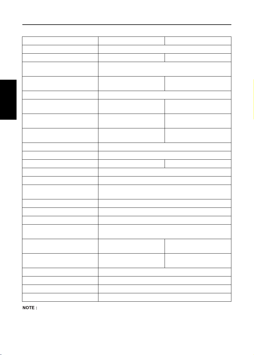
52 SPECIFICATIONS
Model D1803-M-DI-E3 V2403-M-DI-E3
Type Vertical, water-cooled, 4-cycle diesel engine
Number of cylinders 3 4
Bore and stroke mm (in.)
Total displacement L (cu.in.)
1.826
(111.39)
87 × 102.4
(3.43 × 4.04)
(148.53)
Combustion chamber Re-entrant Type (Direct Injection)
SAE Gross Intermittent kW / rpm
H.P. ( SAEJ 1349 ) (HP / rpm)
ENGLISH
SAE NET Intermittent kW / rpm
H.P. ( SAEJ 1349 ) (HP / rpm)
SAE NET Continuous kW / rpm
H.P. ( SAEJ 1349 ) (HP / rpm)
27.9/2700
(37.4/2700)
26.7/2700
(35.8/2700)
23.2/2700
(31.1/2700)
36.5/2700
(48.9/2700)
35.1/2700
(47.1/2700)
30.5/2700
(40.9/2700)
Maximum bare speed rpm 2900
Minimum bare idling speed rpm 850 to 950
Order of firing 1-2-3 1-3-4-2
Direction of rotation Counter-clockwise (viewed from flywheel side)
Injection pump Bosch "K" Type mini pump
Injection pressure
1st Stage 18.6 MPa (190 kgf/cm
2nd Stage 22.6 MPa (230 kgf/cm
2
, 2702 psi)
2
Injection timing (Before T.D.C.) 0.105 rad (6°)
Compression ratio 20.5
Fuel Diesel Fuel No.2-D or No.2-DLS
Lubricant
(API classification)
Dimension mm (in.)
(length × width × height)
Dry weight
(BB Spec.) kg (l bs.)
575.9 × 499.0 × 684.0
(22.7 × 19.7 × 26.9)
151.0 (332.9) 184.0 (406)
above CF grade
670.9 × 499.0 × 684.0
(26.4 × 19.7 × 26.9)
Starting system Cell starter (with glow plug)
Starting motor 12 V, 2.0 kW
Charging generator 12 V, 480 W
Recommended battery capacity 12 V, 100 to 120 AH
2.434
, 3271 psi)
A Specifications are subject to change without notice.
Page 64

Model V3600-E3 V3600-T-E3
Type Vertical, water-cooled, 4-cycle diesel engine
Number of cylinders 4
Bore and stroke mm (in.) 98 × 120 (3.86 × 4.72)
To tal di spl aceme nt L (cu.i n.) 3. 620 (22 0.9 )
Combustion type Spherical type (E-TVCS)
SAE Gross Intermittent
kW / rpm
H.P. (SAEJ1349) (HP / rpm)
SAE NET Intermittent
kW / rpm
H.P. (SAEJ1349) (HP / rpm)
SAE NET Continuous kW / rpm
H.P. (SAEJ1349) (HP / rpm)
49.8/2600
(66.8/2600)
46.3/2600
(62.1/2600)
40.2/2600
(53.9/2600)
63.0/2600
(84.5/2600)
59.3/2600
(79.5/2600)
51.5/2600
(69.0/2600)
Maximum bare speed rpm 2800
Maximum bare idling speed rpm
775 to 825
Order of firing 1-3-4-2
Direction of rotation Counter-clockwise (viewed from flywheel side)
Injection pump Bosch type mini pump
Injection pressure MPa
(kgf / cm
2
, psi)
13.73 (140, 1991)
Injection timing (Before T.D.C.) 0.14 rad (8°) 0.07 rad (4°)
Compression ratio 22.6 21.8
Fuel Diesel fuel oil No.2-D
Lubricant (API classification) above CF grade
Di mensi on mm (in.)
(length × width × height)
745 × 536 × 741.5
(29.33 × 21.10 × 29.19)
745 × 538.5 × 794
(29.33 × 21.20 × 31.26)
Dry weight kg (lbs.) 264 (582) 271 (597)
Starting system Cell starter (with glow plug)
Starting motor 12 V, 3.0 kW
Charging generator 12 V, 540 W
Recommended battery capacity 12 V, 136 AH
53SPECIFICATIONS
ENGLISH
A Specifications are subject to change without notice.
Page 65

54 SPECIFICATIONS
Model V3300-E3BG
Type Vertical, water-cooled, 4-cycle diesel engine
Number of cylinders 4
Bore and stroke mm (in.) 98 × 110 (3.86 × 4.33)
Total displacement L(cu.in.) 3.318 (202.49)
Combustion type Spherical type (E-TVCS)
SAE NET Continuous kW / rpm
H.P. (SAEJ1349) (HP / rpm)
SAE Stand by kW / rpm
H.P. (SAEJ1349) (HP / rpm)
ENGLISH
Maximum bare speed rpm 1890
28.1/1800 (37.7/1800)
23.0/1500 (30.8/1500)
31.0/1800 (41.6/1800)
25.4/1500 (34.1/1500)
Order of firing 1-3-4-2
Direction of rotation Counter-clockwise (viewed from flywheel side)
Injection pump Bosch type mini pump
Injection pressure MPa
(kgf / cm
2
, psi)
13.73 (140, 1991)
Injection timing (Before T.D.C.) 0.17 rad (10°)
Compression ratio 22.6
Fuel Diesel fuel oil No.2-D
Lubricant (API classification) above CF grade
Dime nsi on mm (in.)
(length × width × height)
769 × 536 × 770
(30.28 × 20.10 × 30.31)
Dry weight kg (lbs.) 276 (608)
Starting system Cell starter (with air heater)
Starting motor 12 V, 2.5 kW
Charging generator 12 V, 540 W
Recommended battery capacity 12 V, 88 AH
A Specifications are subject to change without notice.
A Flywheel type is SAE clutch No.11-1/2, SAE clutch No.10 or its equivalent.
A Flywheel housing type is SAE No.3 or its equivalent.
A Governor drop is within 5%.
A Continuous will operate at the stated rating continuously and have a 10% overload capability for one hour in 12
hours.
A Standby will operate at the stated full rating for one hour in 12 hours. No overload capacity is specified for this rating.
Page 66

Model V3600-T-E3BG
Type Vertical, water-cooled, 4-cycle diesel engine
Number of cylinders 4
Bore and stroke mm (in.) 98 × 120 (3.86 × 4.72)
To tal di spl aceme nt L (cu.i n.) 3. 620 ( 220 .9)
Combustion type Spherical type (E-TVCS)
SAE NET Continuous kW / rpm
H.P. (SAEJ1349) (HP / rpm)
SAE Stand by kW / rpm
H.P. (SAEJ1349) (HP / rpm)
39.2/1800 (52.5/1800)
32.1/1500 (43.0/1500)
43.1/1800 (57.8/1800)
35.3/1500 (47.3/1500)
Maximum bare speed rpm 1890
Order of firing 1-3-4-2
Direction of rotation Counter-clockwise (viewed from flywheel side)
Injection pump Bosch type mini pump
Injection pressure MPa
(kgf / cm
2
, psi)
13.73 (140, 1991)
Injection timing (Before T.D.C.) 0.09 rad (5°)
Compression ratio 21.8
Fuel Diesel fuel oil No.2-D
Lubricant (API classification) above CF grade
Dime nsi on mm (in.)
(length × width × height)
769 × 539 × 803
(30.28 × 21.22 × 31.61)
Dry weight kg (lbs.) 283 (624)
Starting system Cell starter (with air heater)
Starting motor 12 V, 3.0 kW
Charging generator 12 V, 540 W
Recommended battery capacity 12 V, 88 AH
55SPECIFICATIONS
ENGLISH
A Specifications are subject to change without notice.
A Flywheel type is SAE clutch No.11-1/2, SAE clutch No.10 or its equivalent.
A Flywheel housing type is SAE No.3 or its equivalent.
A Governor drop is within 5%.
A Continuous will operate at the stated rating continuously and have a 10% overload capability for one hour in 12
hours.
A Standby will operate at the stated full rating for one hour in 12 hours. No overload capacity is specified for this rating.
Page 67

56 WIRING DIAGRAMS
WIRING DIAGRAMS
[Z482-E3, Z602-E3, D722-E3, D782-E3, D902-E3]
EU standard for Alternator (Energize to stop)
ENGLISH
Page 68

[Z482-E3, Z602-E3, D722-E3, D782-E3, D902-E3]
KEA standard for Alternator (Energize to stop)
57WIRING DIAGRAMS
ENGLISH
Page 69

58 WIRING DIAGRAMS
[Z482-E3, Z602-E3, D722-E3, D782-E3, D902-E3]
EU standard for Dynamo (Energize to stop)
ENGLISH
Page 70

[Z482-E3, Z602-E3, D722-E3, D782-E3, D902-E3]
KEA standard for Dynamo (Energize to stop)
59WIRING DIAGRAMS
ENGLISH
Page 71

60 WIRING DIAGRAMS
[D1005-E3, D1105-E3, D1105-TE3, D1305-E3, V1505-E3, V1505-TE3, D1005-E3BG, D1105-E3BG, V1505-E3BG]
EU standard (Energize to run)
ENGLISH
The parts boxed in are reference, NOT equiped for standard engine spec.
Non marked wire dia. is 0.8~1.25 mm
2
.
Page 72
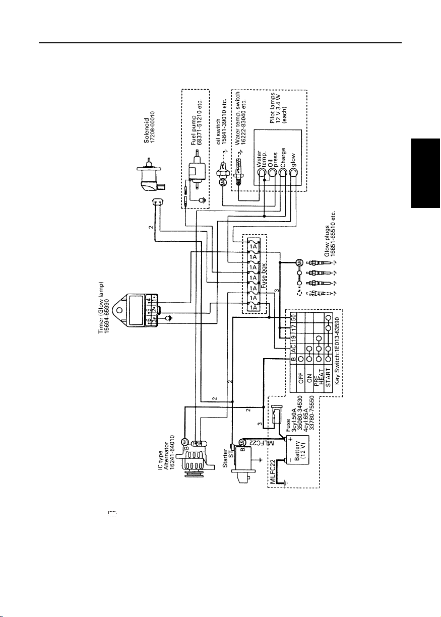
[D1005-E3, D1105-E3, D1105-TE3, D1305-E3, V1505-E3, V1505-TE3, D1005-E3BG, D1105-E3BG, V1505-E3BG]
KEA/SAE standard (Energize to run)
61WIRING DIAGRAMS
ENGLISH
The parts boxed in are reference, NOT equiped for standard engine spec.
Non marked wire dia. is 0.8~1.25 mm
2
.
Page 73

62 WIRING DIAGRAMS
[D1503-M-E3, D1703-M-E3, D1803-M-E3, V2003-M-E3, V2203-M-E3, V2403-M-E3, V2403-M-T-E3, D1803-M-DI-E3,
V2403-M-DI-E3]
ENGLISH
Page 74

[V3600-E3, V3600-T-E3, V3300-E3BG, V3600-T-E3BG]
Fuse
(10A or less)
Inner connection of key switch
Oil lamp
12V1.7W
~3.4W
63WIRING DIAGRAMS
Position
Alternator
1 = Optional
Key switch
Lamp timer
(Glow lamp)
Slow blow fuse (65A)
Recommended P/N
33780-75551
Battery
12V
Starter
12V3.2kW
Idle
Accel
Solenoid
Water temp
warning lamp
12V1.7W
~3.4W
Charge lamp
12V1.7W
~3.4W
Glow lamp
12V1.7W
~3.4W
Thermo-switch
ENGLISH
Oil switch
 Loading...