

Page 1

NOTE: This manual contains both 981-0517 and 981-0527
Page 2
WORKSHOP
MANUAL
DIESEL
05
SERIE
05
SERIES
REIHE
ENGINE
05
Page 3

Redistribution or publication of this document,
by any means, is strictly prohibited.
Page 4
TO
Redistribution or publication of this document,
by any means, is strictly prohibited.
This Workshop Manual has been prepared to provide servicing personnel with
information on the mechanism, service and maintenance of
SERIES.
each section.
It
is divided into
two
THE
parts, “Mechanism” and “Disassembling and Servicing” for
READER
KUBOTA
Diesel Engines
05
Mechanism
Information on the construction and function are included for each engine section. This
part should be understood before proceeding with troubleshooting, disassembling and
servicing.
H
Disassembling and Servicing
Under the heading ”General” section comes general precautions, troubleshooting, lists
of servicing specifications and periodic inspection items. For each engine section, there
are “Checking and Adjustment“, “Disassembling and Assembling”, and “Servicing” which
cover procedures, precautions, factory specification and allowable limits.
All
the engines that have been manufactures since January of
engines.
The mark
[E]
in the WSM refers to the said clean engine.
1994
are clean exhaust
All
information, illustrations and specifications contained
the latest production information available at the time of publication.
The right is reserved to make changes in all information
Due to covering many models of this manual, illustration or picture being used have not
been specified as one model.
@
KUBOTA
Corporation
1996
in
this manual are based on
at
any time without notice.
May
1996
01640200040
Page 5
Ce manuel d’atelier a 4th pr4par6 pour permettre au personnel d’entretien de disposer
Redistribution or publication of this document,
by any means, is strictly prohibited.
e’informations sur les m4canismesI les entretienes et la maintenance des moteurs
KUBOTA
Demontage et entretien”.
H
Mbchanisrnes
Des informations sur la construction et les fonctions sont donn6es pour chaque partie
du moteur. Cette partie du manuel doit &re comprise avant de commencer les operations
de recherche des anomalies, de demontage et d’entretien.
H
DBmontage et entretien.
Sous
de recharche des anomalies et les listes de caract’eristiques d’entretien et points de
vbrification periodique. Pour chaque partie du moteur, on trouvera les titles “Verification et
reglage“, “DBmontage et remontage“ et “Entretien”
caractbristiques d’usine et les limites de service.
Les
d’echappement non polluants.
Ces moteurs non polluants sont indiqubs dans le manuel d’atelier par la lettre
Toutes les informations, illustrations et specifications contenues dans ce manuel sont
bas6es sur les dernihres informations de production disponibles au moment de
publication.
tout moment et sans pr6avis.
Ce manuel couvrant de nombreux mod&les, les illustrations
donnees
Diesel moteur de s4rie
le titre ”G6neralit4s on trouvera des recommandations gen6ralesl les procedures
moteurs fabriqu4s depuis Janvier 1994 ont 4t6 consus de fason A produire
B
05.
II
est dives4 en deux sections: “Mecanismes” et
oh
sont reprises les precautions, les
[q.
la
Nous
nous
B
titre indicatif.
rbservons le droit de modifier tout element de ces informations,
ou photos utilis4es sont
A
0
KUBOTA
Corporation 1996
Mai
1996
01640Z00050F
Page 6

FUR DEN LESER
Redistribution or publication of this document,
by any means, is strictly prohibited.
Dieses Handbuch
Betrieb und die wartung der KOBOTA-dieselmotoren Serienmotormit
zwei Teile, “Funktion” und “ausbau und Wartung” aufgegliedert.
H
Mechanismus
Fur jeden Motorabschnitt werden Informationen bezuglich Konstruktion und Funktion
gegeben. Diesel Teil sollte sorgf;altig gelesen werden, bevor mit der Storungssuche, dem
Ausbau und der wartung begonnen wird.
H
Ausbau und Wartung
Der Abschnitt “allgemeines” beinhaltet allgemeine Vorkehrungen, Storungssuchen und
Listen von Wartungsdaten sowie von regelmat3ig
Motorabschnitt ist ein Kapitel “Prijfung und Einstellung”, “Aus-und Einbau” und “Wartung”
vorgesehen, welches uber Verfahrensweisen, Vorkehrungen, Werkdaten und zulassige
Grenzwerte AufschluB gibt.
Alle Motoren, die ab Januar
Die marke
Allen in diesem Hanbuch enthaltenen Informationen, Abbildungen und technischen
Merkmalen liegen die letzten, zum Zeitpunkt der Veroffentlichung verfiigbaren
lnformationen zugrunde. Eine hderung aller lnformationen
Ankundigung bleibt vorbehalten.
Da in diesem Handbuch mehrere Modelle beschrieben werden, wurden die jeweilig
verwendeten abbildungen odre Bilder nicht fiir ein einzelnes Modell pr&isiert.
[El
sol1
dem Wartungspersonnal lnformationen uber die Funktion, den
zu
uberpriifenden Teilen. Fiir jeden
1994 hergestellen werden sind Sauberab-Motoren.
bezieht sich auf den vorgenannten sauberen Motor.
zu
05
lieffern.
jeder Zeit und ohne
Es
ist in
@
KUBOTA Corporation 1996
Mai 1996
01640Z00060D
Page 7
05
Redistribution or publication of this document,
by any means, is strictly prohibited.
SERIES
WSM,
01640
SAFETY
INSTRUCTIONS
IOOOOF00021
~00000F00030
00000F00040
~1
rlr
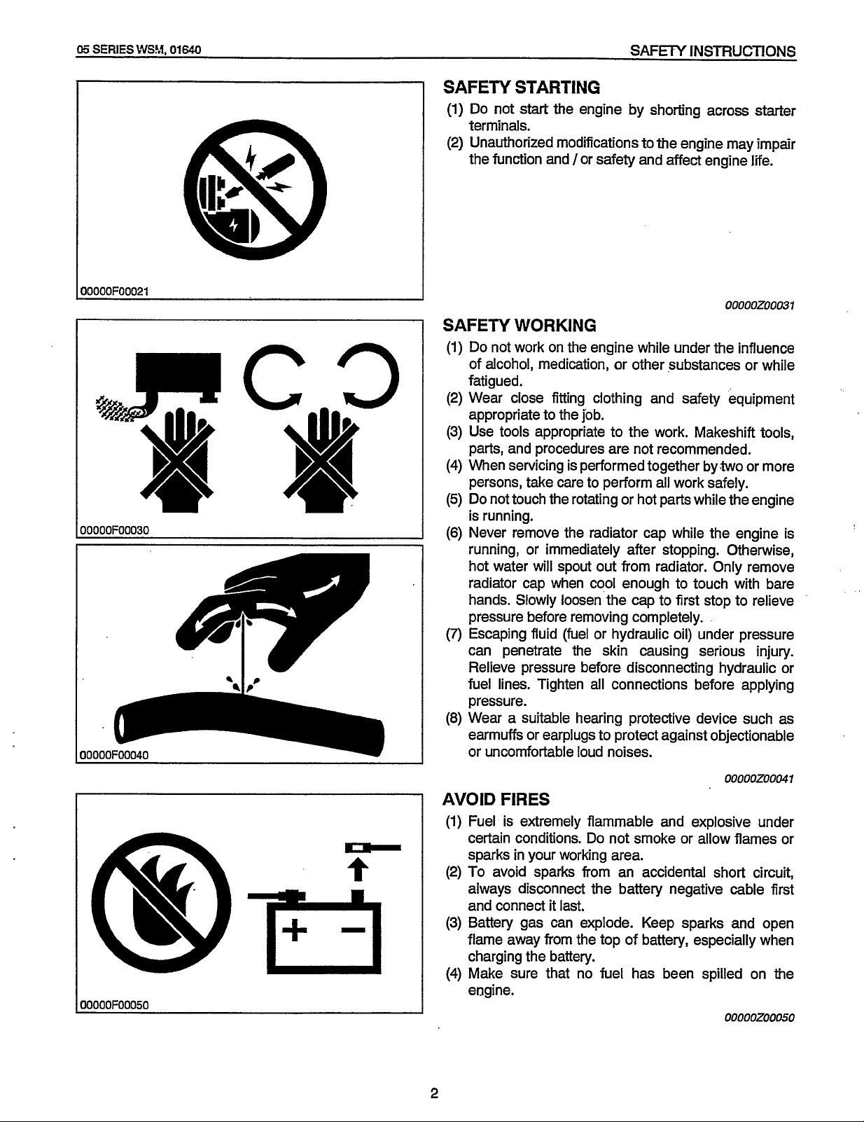
SAFETY
(1)
Do
terminals.
(2)
Unauthorized modifications
the
STARTING
not
start
function and /or safety and
SAFETY WORKING
(1)
Do
not work on
of
alcohol, medication, or other substances
fatigued.
(2)
Wear
appropriate to
(3)
(4)
When servicing
(5)
I
(6)
(7)
I
fuel
(8)
close
Use
tools appropriate
parts, and procedures
persons, take
Do
not touch the rotating or hot parts while the engine
is
running.
Never remove the radiator cap while the engine
running, or immediately after stopping. Otherwise,
hot water will spout
radiator
hands. Slowly loosen
pressure before removing completely.
Escaping fluid
can penetrate the skin causing serious injury.
Relieve pressure before disconnecting hydraulic or
pressure.
Wear a suitable hearing protective device such
earmuffs
or
cap when cool enough
lines.
Tighten
or
earplugs
uncomfortable loud noises.
the
engine by shorting across starter
to
the engine may impair
affect
engine
the
engine while under
fitting clothing and safety equipment
the
job.
to
the
work.
Makeshift
are
not recommended.
is
performed together by<two or more
care
to perform
all
work safely.
life.
00000200031
the
influence
or
while
tools,
is
out
from radiator. Only remove
to
touch with bare
the
cap
to
first
stop
to
relieve
(fuel
or hydraulic
all
connections before applying
oil)
under pressure
as
to
protect against objectionable
l0000F00050
AVOID
(1)
(2)
(3)
(4)
2
FIRES
Fuel
is
extremely flammable and explosive under
Do
certain conditions.
sparks in your working
To
avoid sparks from an accidental short circuit,
always disconnect the battery negative cable first
and connect
Battery gas can explode. Keep sparks and open
flame
away from the top
charging the battery.
Make
engine.
sure
it
last.
that
not smoke or allow flames or
area.
of
battery, especially when
no fuel has been spilled
ooooozooo41
on
the
000002000050
Page 8
SAFETY
Redistribution or publication of this document,
by any means, is strictly prohibited.
INSTRUCTIONS
05
SERIES
WSM,
01640
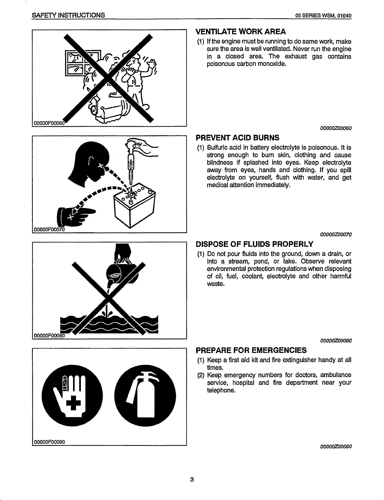
VENTILATE
(1)
If the engine must be running to do same work, make
sure the area is well ventilated. Never run the engine
in a closed area. The exhaust gas contains
poisonous carbon monoxide.
WORK
AREA
00000200060
PREVENT ACID BURNS
(1)
Sulfuric acid in battery electrolyte is poisonous.
strong enough to burn skin, clothing and cause
blindness if splashed into eyes. Keep electrolyte
away from eyes, hands and clothing.
on
electrolyte
medical attention immediately.
yourself, flush with water, and get
If
It
is
you spill
00000200070
DISPOSE
(1)
Do
into a stream, pond, or lake. Observe relevant
environmental protection regulations when disposing
of
waste.
OF
FLUIDS PROPERLY
not pour fluids into the ground, down a drain,
oil,
fuel, coolant, electrolyte and other harmful
or
ooooozomo
PREPARE FOR EMERGENCIES
(1)
Keep a first aid kit and fire extinguisher handy at all
times.
(2) Keep emergency numbers for doctors, ambulance
service, hospital and fire department near your
telephone.
I
OOOOOFOOOQO
ooooozooo9o
3
Page 9
Q5
Redistribution or publication of this document,
by any means, is strictly prohibited.
SWES
CVSM,
01640
A
LA
SECURITE
INSTRUCTIONS
D’ABORD
DE
SECURITE
DANGER : lndique une situation eminemment dangereuse, des blessures graves
la
AVERTISSEMENT : lndique une situation potentiellement dangereuse, des blessures graves
I
aATTENT1oN
IMPORTANT : Ceci indique que si les instructions ne sont pas suivies, des dommages ou degats
1
NOTA
i
peuvent sunrenir si cette situation n’est pas evitee.
la mort peuvent survenir si cette situation n’est pas evitee.
:
lndique une situation potentiellement dangereuse, des blessures mineures
ou
graves peuvent survenir si cette situation n’est pas evitee.
peuvent &re occasionnes
:
Donne des informations utiles.
a
I’equipement
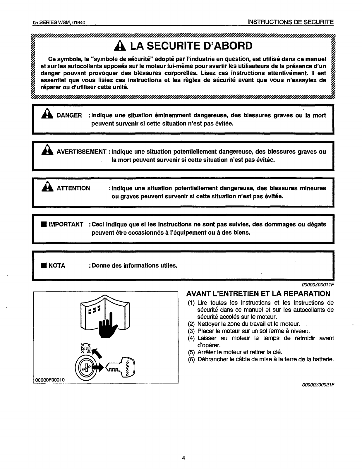
AVANT L’ENTRETIEN ET
(1)
(2)
(3)
(4)
(5)
(6)
ou
a
des biens.
Lire toutes les instructions et les instructions de
securite dans ce manuel et sur les autocollants de
securite accoles sur le moteur.
Nettoyer la zone du travail et le moteur.
Placer le moteur sur un
hisser au moteur le temps de refroidir avant
d’operer.
ArrGter le moteur et retirer la cle.
Debrancher le cable de mise
LA
REPARATION
sol
ferme h niveau.
a
la
terre de
ou
la mort
ou
OOOOOZOOOllF
la
batterie.
I
I
I
00000Z00021F
4
Page 10
INSTRUCTIONS
Redistribution or publication of this document,
by any means, is strictly prohibited.
DE
SECURITE
05
SERIES
WSM,
01640
rlr
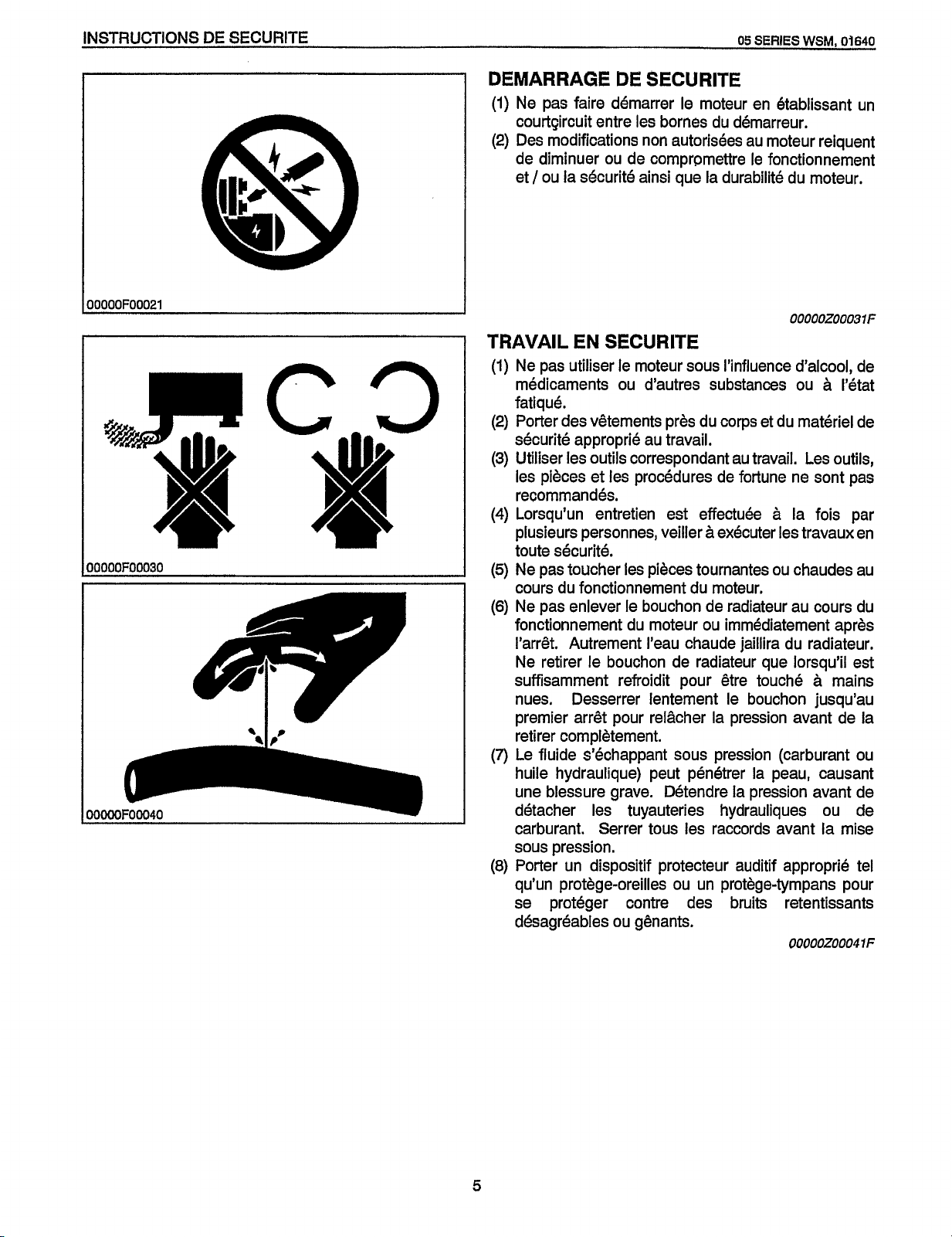
DEMARRAGE
(1)
Ne pas faire demarrer le moteur en etablissant
courtgircuit entre les bornes
(2)
Des modifications
de diminuer
/
ou
et
TRAVAIL
(1)
Ne pas utiliser le moteur
medicaments
fatique.
(2)
Porter des vQtements
securite approprie au travail.
(3)
Utiliser les
les pieces et les procedures de fortune ne
recommandes.
(4)
Lorsqu’un
plusieurs personnes, veiller
securite.
toute
(5)
Ne pas toucher les pieces tournantes
cours
(6)
Ne pas enlever le
fonctionnement
I’arrQt. Autrement I’eau chaude jaillira
Ne retirer le
suffisamment refroidit
nues. Desserrer lentement le
I
premier arrdt
retirer complbtement.
(7)
Le fluide s’echappant
huile hydraulique) peut penetrer la peau, causant
une blessure grave. DBtendre la pression avant de
detacher les tuyauteries hydrauliques
carburant.
sous
pression.
(8)
Porter
qu’un
se proteger contre des
desagreables
DE
SECURITE
du
demarreur.
non
autorisees au moteur reiquent
ou
de comprpmettre le fonctionnement
la securite ainsi que la durabilite
EN SECURITE
sous
I’influence d’alcool, de
ou
d’autres substances
pres
du
corps et
outils
correspondant au travail. Les
entretien
du
fonctionnement
bouchon
est effectuee
bouchon
du
moteur
de radiateur que
pour
A
executer les travaux en
du
moteur.
de radiateur au cours
ou
immediatement aprds
Qtre touche a mains
bouchon
pour
relgcher la pression avant de la
sous
pression (carburant
Serrer
un
dispositif
protdge-oreilles
tous
les raccords avant la mise
protecteur auditif approprie tel
ou
un
protdge-tympans
bruits
ou
gdnants.
du
moteur.
00000Z00031F
ou
21
du
materiel de
outils,
sont
a
la
fois
ou
chaudes au
du
radiateur.
lorsqu’il
jusqu’au
ou
retentissants
0000020004
un
l’etat
pas
par
du
est
ou
de
pour
1
F
5
Page 11
05
Redistribution or publication of this document,
by any means, is strictly prohibited.
SERIES
\VS!.I,
01640
INSTRUCTIONS
DE
SECURITE
d
I
-ERESFELM
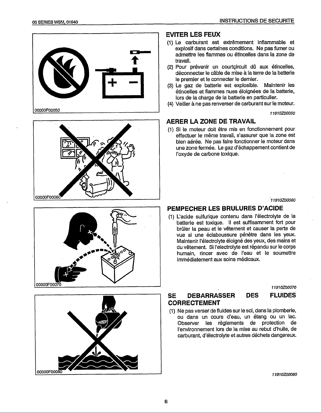
(1)
Le carburant est exbhement inflammable et
explosif dans certaines conditions. Ne pas fumer
admettre les flammes ou etincelles dans
travail.
(2)
Pour prevenir un courtGircuit dO aux 6tincelles,
a
deconnecter le cable de mise
le premier et le connecter le dernier.
(3)
Le gaz de batterie est explosible. Maintenir les
etincelles et flarnmes nues eloignees de
la
lors de la charge de
(4)
Veiller a ne pas renverser de carburant sur le moteur.
AERER
(1)
LA
ZONE
Si
le moteur doit 6tre mis en fonctionnement pour
effectuer le mime travail, s’assurer que la zone est
bien aeree. Ne pas faire fonctionner le moteur dans
une zone fermee. Le gaz d’echappement contient de
I’oxyde de carbone toxique.
batterie en particulier.
DE TRAVAIL
la terre de
la
la
la
11970Z00050
ou
zone de
batterie
batterie,
17910Z00060
PEMPECHER LES BRULURES D’ACIDE
(1)
L‘acide sulfurique contenu dans I’electrolyte de la
II
batterie est toxique.
brQler la peau
vue si une eclaboussure penetre dans les yeux.
Maintenir I’electrolyte eloigne des yeux, des mains et
du
vitement.
humain, rincer avec de I’eau et le soumettre
immediatement aux soins medicaux.
et
le v6tement et causer la perte de
Si
I’electrolyte est repandu sur le corps
SE DEBARRASSER
est suffisamment fort pour
71970Z00070
DES
FLUIDES
CORRECTEMENT
(1)
Ne pas verser de fluides sur le
ou
dans
un
cours d’eau, un etang
Observer les reglements de protection de
I’environnement lors de
carburant, d’electrolyte et autres dechets dangereux.
sol,
dans la plomberie,
ou
un lac.
la
mise au rebut d‘huile, de
11910Z00080
6
Page 12
INSTRUCTIONS DE
Redistribution or publication of this document,
by any means, is strictly prohibited.
SECURITE
05
SERIES
SE
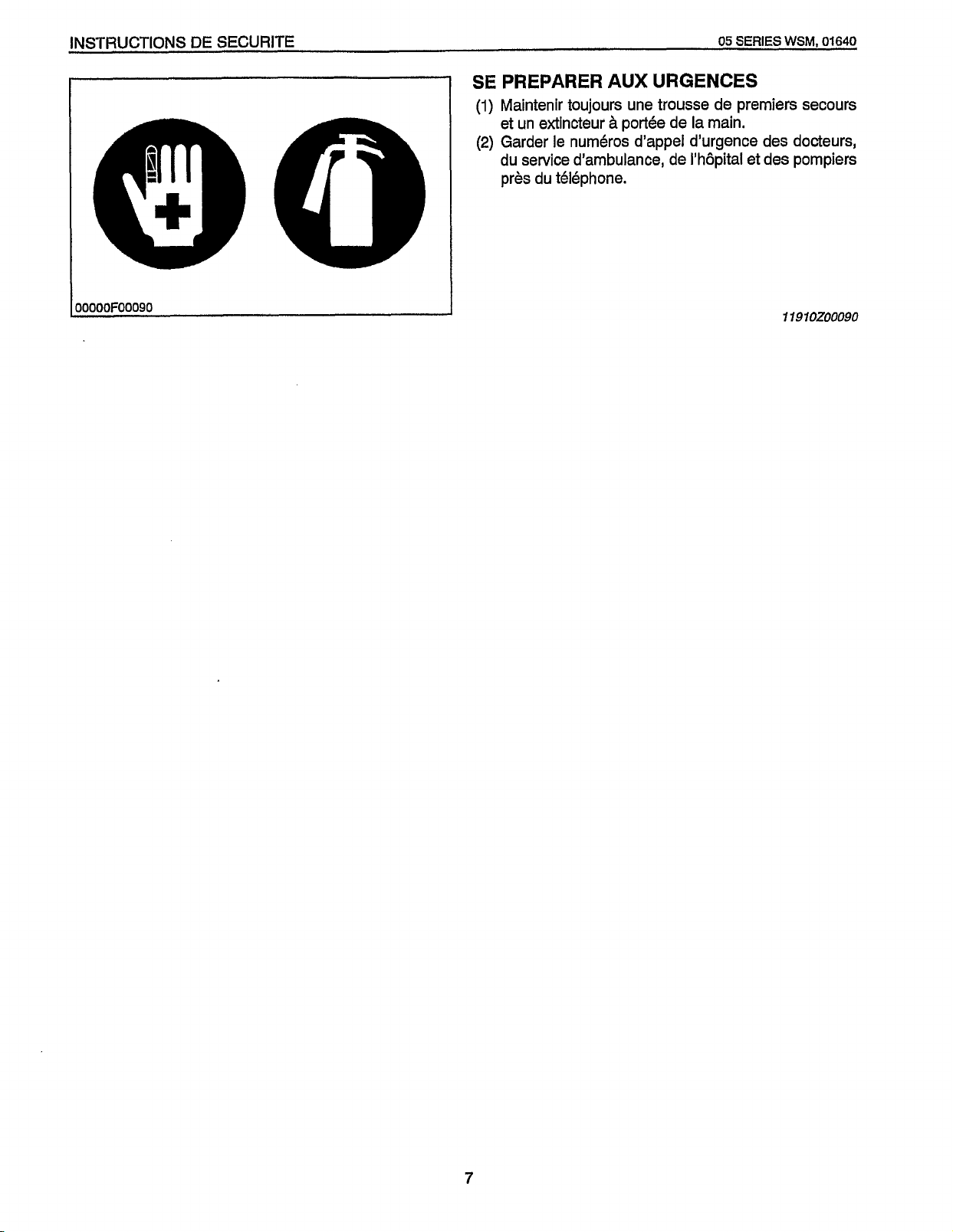
PREPARER AUX URGENCES
(1)
Maintenir toujours une trousse de premiers secours
a
et un extincteur
(2)
Garder le numdros d’appel d’urgence des docteurs,
portde de la main.
WSM,
du service d’ambulance, de I’hbpital et des pompiers
pres du tdl6phone.
01640
~OOOOOFOOO9O
I
11910200090
7
Page 13
05
Redistribution or publication of this document,
by any means, is strictly prohibited.
SERIES
WSM,
01640
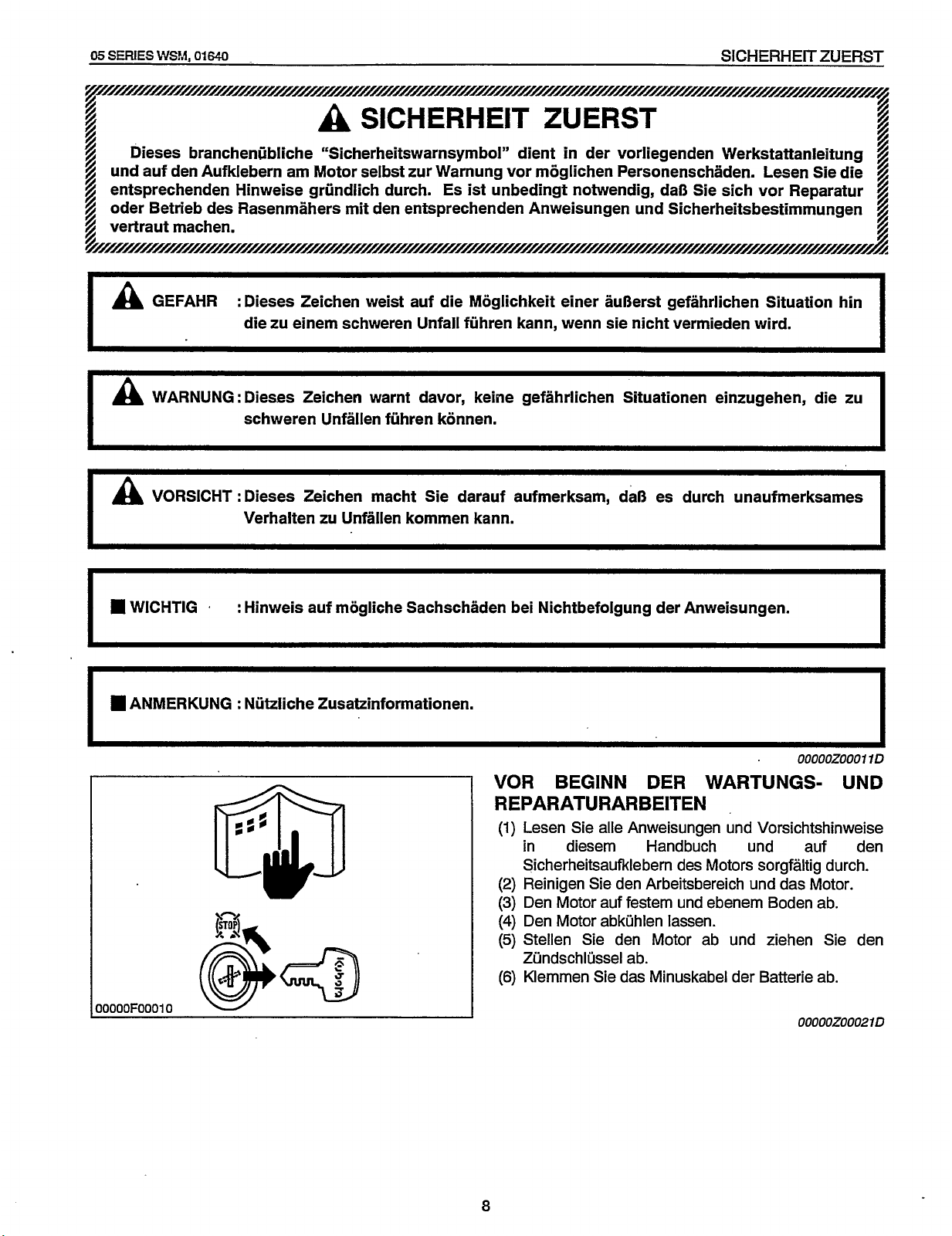
GEFAHR
I"
WARNUNG : Dieses Zeichen warnt davor, keine gefahrlichen Situationen einzugehen, die zu
VORSICHT : Dieses Zeichen macht Sie darauf aufmerksam, daS es durch unaufmerksames
I"
SICHERHEITZUERST
A
SICHERHEIT
:
Dieses Zeichen weist auf die Moglichkeit einer auSerst gefahrlichen Situation
die zu einem schweren Unfall fuhren kann, wenn sie nicht vermieden wird.
schweren Unfallen fuhren konnen.
Verhalten zu Unfallen kommen kann.
ZUERST
hin
I
I
I
:
W
WlCHTlG
ANMERKUNG : Nutzliche Zusatzinformationen.
Hinweis auf mogliche Sachschaden bei Nichtbefolgung der Anweisungen.
OOOOOZOOOl
VOR BEGINN DER WARTUNGS- UND
REPARATURARBEITEN
(1)
Lesen Sie alle Anweisungen und Vorsichtshinweise
in diesem Handbuch und auf den
Sicherheitsaufklebern des Motors sorgfaltig durch.
(2)
Reinigen Sie den Arbeitsbereich und das Motor.
(3)
Den Motor auf festem und ebenem Boden ab.
(4)
Den Motor abkuhlen lassen.
(5)
Stellen Sie den Motor ab und ziehen Sie den
Zundschlussel ab.
(6)
Klemmen Sie das Minuskabel der Batterie ab.
00000Z000210
10
8
Page 14
SICHERHEIT ZUERST
Redistribution or publication of this document,
by any means, is strictly prohibited.
,
JOOOOF00021
05
SERIES
SIC
H
E R H
ElTS H
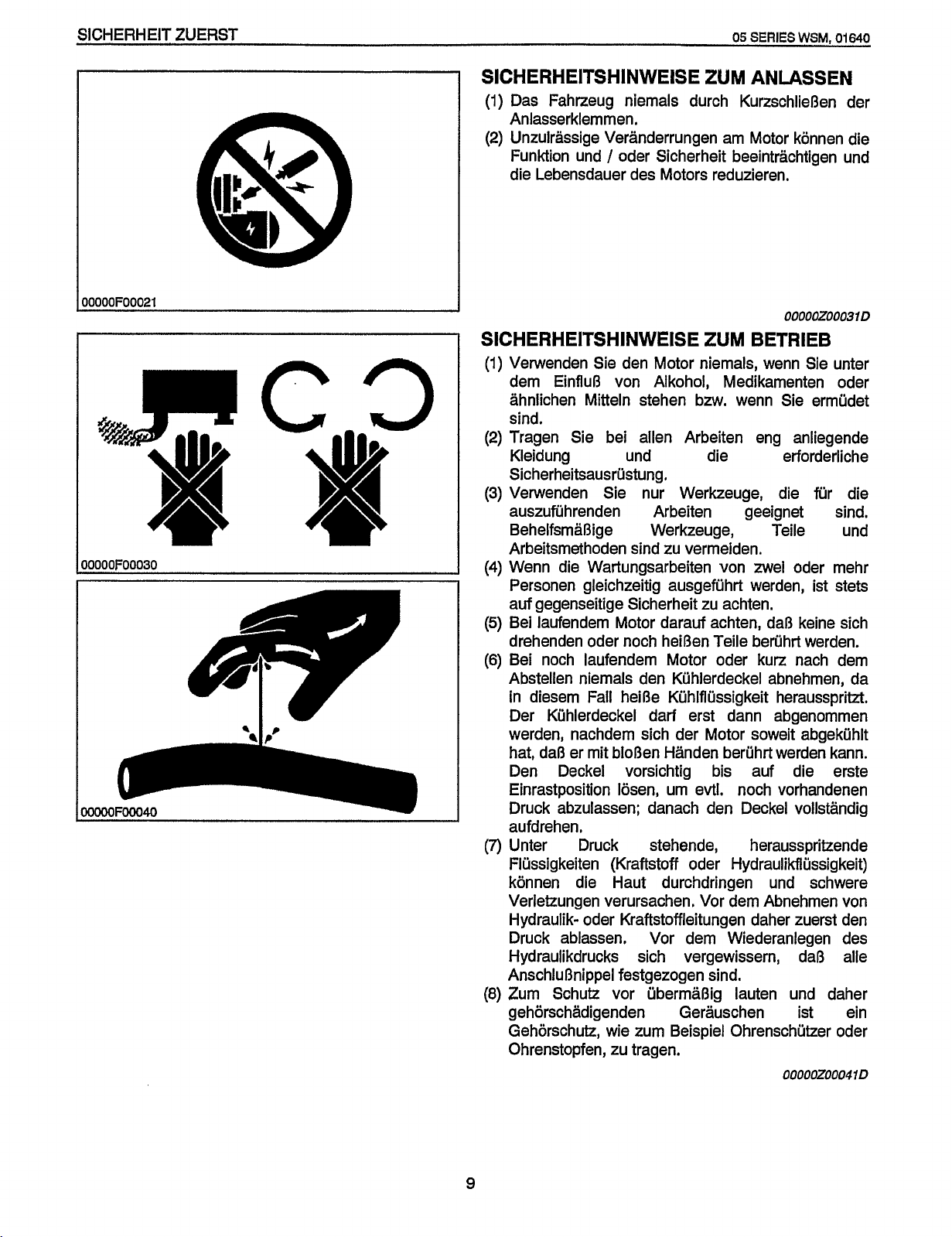
(1)
Das Fahrzeug niemals durch KurzschlieOen der
Anlasserklemmen.
(2)
Unzuirassige Veranderrungen am Motor konnen die
Funktion und
die Lebensdauer des Motors reduzieren.
I
N
W
E
IS
E
ZU
M
AN
/
oder Sicherheit beeintrachtigen und
WSM,
US
S
00000Z00031 D
SlCHERHElTSHlNWElSE ZUM BETRIEB
(1)
Verwenden Sie den Motor niemals, wenn Sie unter
dem EinfluO von Alkohol, Medikamenten oder
ahnlichen Mitteln stehen bzw. wenn Sie ermudet
sind.
(2)
Tragen Sie bei allen Arbeiten eng anliegende
Kleidung und die erforderliche
Sicherheitsausrustung,
(3)
Verwenden Sie nur Werkzeuge, die fur die
auszufiihrenden Arbeiten geeignet sind.
BehelfsmaOige Werkzeuge, Teile und
zu
Arbeitsmethoden sind
(4)
Wenn die Wartungsarbeiten von zwel oder mehr
Personen gleichzeitig ausgefuhrt werden, ist stets
auf gegenseitige Sicherheit
(5)
Bei laufendem Motor darauf achten, daO keine sich
drehenden oder noch heiOen Teile beruhrt werden.
(6)
Bei noch laufendem Motor oder kurz nach dem
Abstellen niemals den Kuhlerdeckel abnehmen, da
in
diesem Fall heiRe Kuhlflussigkeit herausspritzt.
Der Kuhlerdeckel darf erst dann abgenommen
werden, nachdem sich der Motor soweit abgekuhlt
hat, daO er mit bloOen Handen berijhrt werden kann.
Den Deckel vorsichtig bis auf die erste
Einrastposition Iosen,
Druck abzulassen; danach den Deckel vollstandig
aufdrehen.
(7)
Unter Druck stehende, herausspritzende
Flussigkeiten (Kraftstoff oder Hydraulikflussigkeit)
konnen die Haut durchdringen und schwere
Verletzungen verursachen. Vor dem Abnehmen von
Hydraulik- oder Kraftstoffleitungen daher zuerst den
Druck ablassen. Vor dem Wiederanlegen des
Hydraulikdrucks sich vergewissern, da8 alle
AnschluBnippel festgezogen sind.
(8)
Zum Schutz vor ubermaOig lauten und daher
gehorschadigenden Gerauschen ist ein
Gehorschutz, wie zum Beispiel Ohrenschutzer oder
Ohrenstopfen,
zu
tragen.
vermeiden.
zu
urn
evtl.
achten.
noch vorhandenen
00000200041
01640
EN
D
9
Page 15
05
Redistribution or publication of this document,
by any means, is strictly prohibited.
SERIES
lOOOOFOOO5O
WS?;I.
07640
SICHERHEIT ZUERST
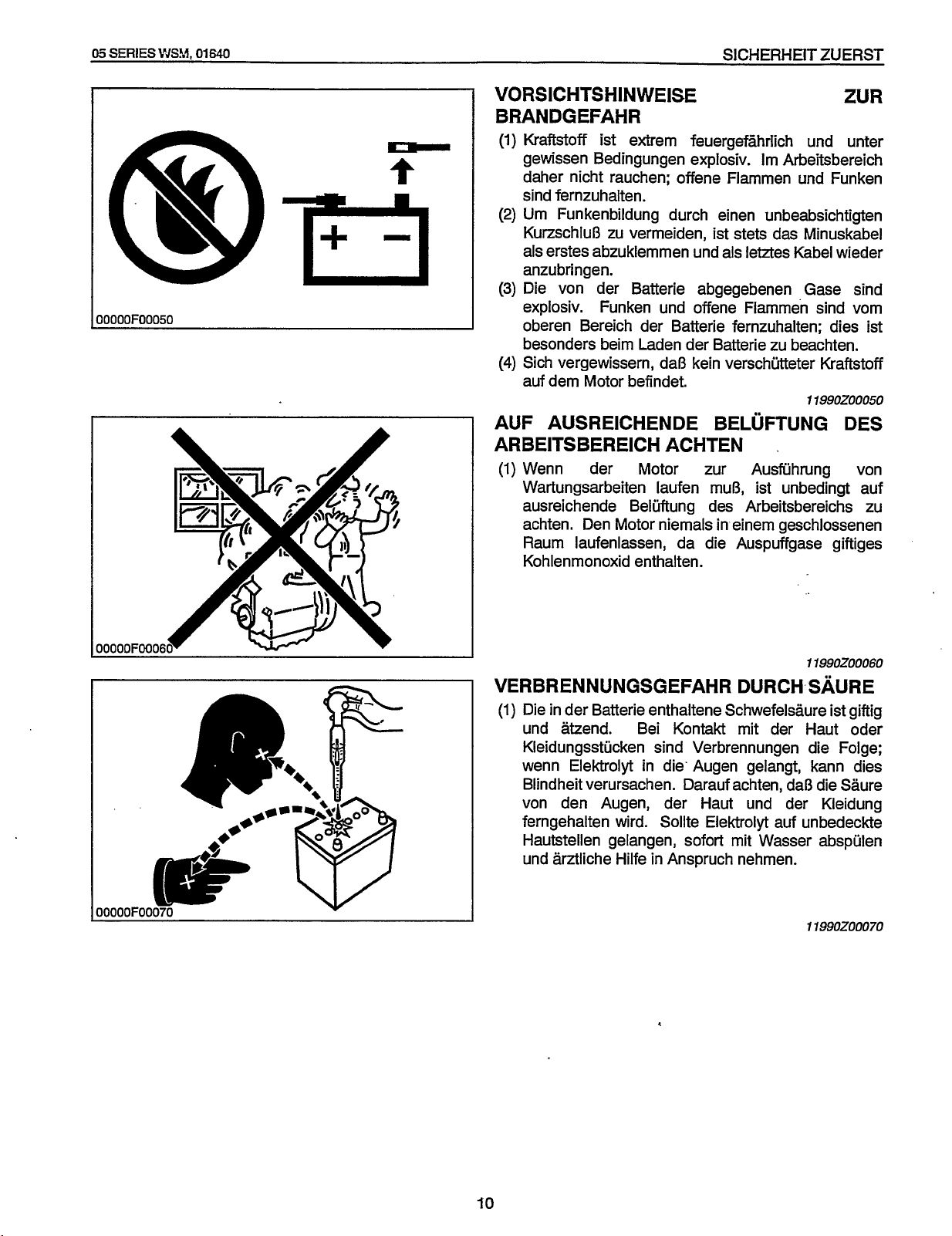
VORSICHTSH IN WEISE ZUR
BRANDGEFAHR
(1)
KraMoff ist extrern feuergefzhrlich und unter
Irn
gewissen Bedingungen explosiv.
Arbeitsbereich
daher nicht rauchen; offene Flarnrnen und Funken
sind fernzuhalten.
(2)
Urn
Funkenbildung durch einen unbeabsichtigten
KurzschluB zu vermeiden, ist stets das Minuskabel
als erstes abzuklernrnen und als letztes Kabel wieder
anzubringen.
(3)
Die von der Batterie abgegebenen Gase sind
explosiv. Funken und offene Flarnrnen sind vorn
oberen Bereich der Batterie fernzuhalten; dies ist
besonders beirn Laden der Batterie
(4)
Sich vergewissern, daB kein verschutteter Kraftstoff
zu
beachten.
auf dem Motor befindet.
11990Z00050
AUF AUSREICHENDE BELUFTUNG DES
ARBEITSBEREICH ACHTEN
(1)
Wenn der Motor zur Ausfuhrung von
Wartungsarbeiten laufen
ausreichende Beluftung des Arbeitsbereichs zu
achten. Den Motor niernals in einern geschlossenen
Raurn laufenlassen, da die Auspuffgase giftiges
Kohlenrnonoxid enthalten.
rnuB,
.
ist unbedingt auf
11990Z00060
VERBRENNUNGSGEFAHRDURCHS~~URE
(1)
Die in der Batterie enthaltene Schwefelsaure ist giftig
und atzend. Bei Kontakt rnit der Haut oder
Kleidungsstucken sind Verbrennungen die Folge;
wenn Elektrolyt in die' Augen gelangt, kann dies
Blindheit verursachen. Darauf achten, daB die Saure
von den Augen, der Haut und der Kleidung
ferngehalten wird. Sollte Elektrolyt auf unbedeckte
rnit
Hautstellen gelangen, sofort
und arztliche Hilfe in Anspruch nehrnen.
,
Wasser abspulen
11990Z00070
Page 16
SICHERHEIT
Redistribution or publication of this document,
by any means, is strictly prohibited.
ZUERST
05
SERIES
WSM,
01640
OOOOOFOOO8O
I
8Q
v
-
FLUSSIGKEITEN
ENTSORGEN
(1)
Flksigkeiten nicht auf den Boden, in den AbfluB
oder gar in einen FluB, Teich oder See gieBen. Beim
Entsorgen von
anderen Schadstoffen stets die betreffenden
Umweltschutzbestimmungen
AUSRUSTUNG FUR
(1)
Stets einen Verbandskasten und einen Feuerloscher
griffbereit halten.
(2)
Die Notrufnummern
Krankenhaus und Feuerwehr in der Nahe des
Telefons aufbewahren.
VORSCHRIFTSMASSIG
01,
Kuhlflussigkeit, EleMrolyt oder
beachten.
11990200080
DEN
NOTFALL
fir
Arzt, Unfallwagen,
OOOOOFOOO9O
11990200090
Page 17
05
Redistribution or publication of this document,
by any means, is strictly prohibited.
SERIESWSM,
01640
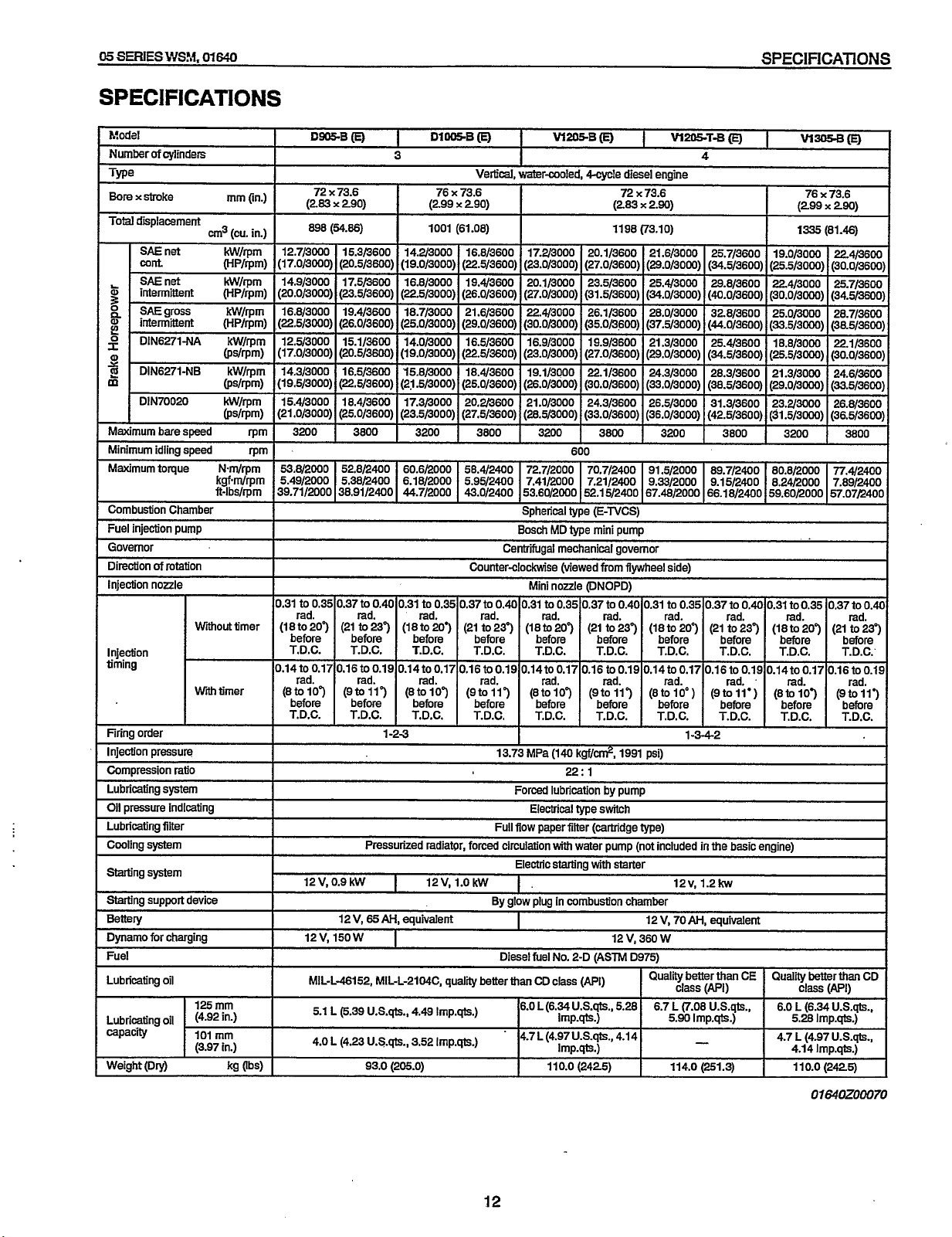
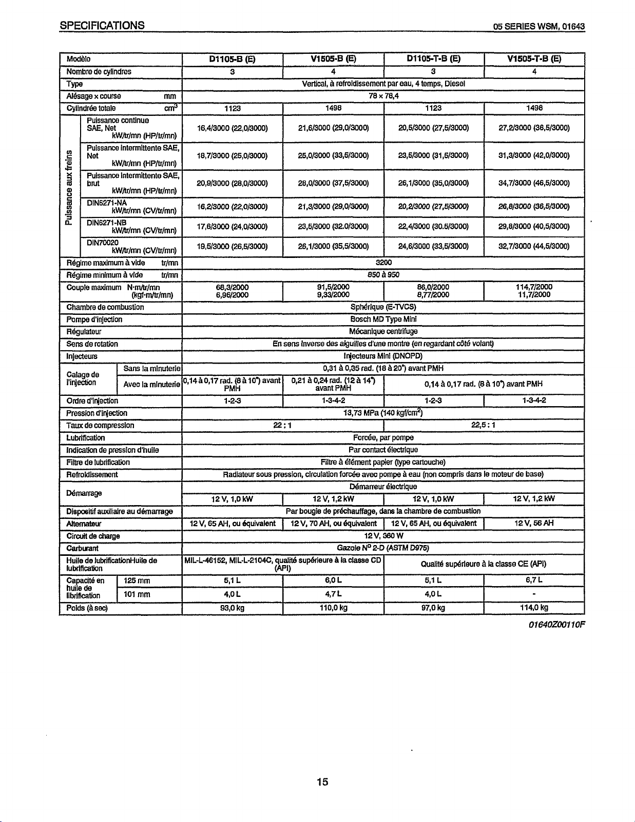
SPECIFICATIONS
SPEC1
FlCATlONS
hfodel
Number
of
cvlinders
I
Type
Bore
x
stroke
Total
displacement
SAE
net
Wnt
SAE
ti
2
p
22
2
m
net
intermittent (HP/rpm)
'
SAE
gross kW/rpm
intermittent (HP/rpm)
DIN6271-NA
DIN6271-NB
DIN70020
Maximumbarespeed
Minimum idling speed
-.
Maximum torque
Combustion Chamber
Fuel
injection pump
Governor
Direction
of
rotation
Injection
nozzle
Wiout
Injection
timing
Witimer
Firing order
Injection pressure
Compression ratio
Lubricating
Oil
system
pressure Indicating
Lubricating filter
Cooling
system
Starting
system
Starting support device
Bettery
Dynamo
for
charging
Fuel
Lubricating
oil
Lubricating oil
capacity
Weight
(Dry)
cm3
Nm/rpm
kgf.m/rpm
ft-lbs/rpm
125
mm
(4.92
101
mm
(3.97
mm
(in.)
(cu.
in.)
kW/rpm
(HP/rpm)
kW/rpm
kW/rpm
@s/rpm)
kW/rpm
@S/rpm)
kW/rpm
@s/rpm)
rpm
mm
timer
in-)
in.)
kg (W
Dsa
I
I
(E)
I
72 x 73.6
(283
x
290) (299 x 290) (283 x 2.90) (299
(54.86)
12.7/3000 15.3/3600 14.2/3000 16.8/3600 17.2/3000 20.1/3600 21.6/3000 25.7/3600 19.0/3000 22.4/3600
(17.0/3000) (20.5/3600) (19.0/3000) (22.5/3600) (23.0/3000) (27.0/3600) (29.0/3000) (34.5/3600) (25.5/3000) (30.0/3600)
14.9/3000 17.5/3600 16.8/3000 19.4/3600 20.1/3000 23.5/3600 25.43000 29.8/3600 22.4/3000 25.7/3600
(20.0/3000j (23.5/3600) (22.5/3000) (26.0/3600) (27.0/3000) (31.5/3600)
16.8/3000 19.4/3600 18.7/3000 21.6/3600 22.43000 26.1/3600 28.0/3000 328/3600 25.0/3000 28.7/3600
(225/3000) (26.0/3600) (25.0/3000) (29.0/3600) (30.0/3000) (35.0/3600) (37.5/3000) (44.0/3600) (33.5/3000) (38.5/3600)
12.5/3000 15.1/3600 14.0/3000 16.5/3600 16.9/3000 19.9/3600 21.3/3000 25.4/3600 18.8/3000 22.1/3600
(17.0/3000) (20.5/3600) (19.0/3000)
14.3/3000 16.5/3600
(19.5/3000)
15.4/3000 18.4/3600
(21.0/3000)
3200 3800
53.8/2000 52.8/2400
5.49/2000 5.38/2400
39.71/2000 38.91/2400
(22.5/3600) (21.5/3000) (25.0/3600)
(25.0/3600) (23.5/3000) (27.5/3600)
DlWB(EJ
I
3
-
76 x 73.6
1001 (61.08) 1198 (73.10)
(22.5/3600)
15.8/3000 18.4/3600 19.1/3000
17.3/3000 20.2/3600 21.0/3000
3200 3800 3200
60.6/2000 58.4/2400 72.7/2000 70.7/2400 91.5/2000 89.7/2400 80.8/2000 T1.4/2400
6.18/2000 5.95/2400 7.41/2000 7.21/2400 9.33/2000 9.15/2400 8.24/2000 7.89/2400
44.7/2000 43.0/2400 53.60/2000 52.15/2400 67.48/2000 66.18/2400 59.60/2000 57.07/2400
I
W205.B
I
Vertical. water-cooled,
(23.0/3000) (27.0/3600)
(26.0/3000)
(28.5/3000)
Soheriml
-r
Bosch
--
600
tvoe
.
..
_r.
MD
type
(E)
I
W205T-Bm
A
4-cvcle
diesel engine
-
72
x
73.6
(34.0/3000)
(29.0/3000)
22.1/3600
(30.0/3600)
24.3/3600 26.5/3000
(33.0/3600) (36.0/3000) (42.5/3600) (31.5/3000) (36.5/3600)
3800 3200
IE-TVCS\
,-
mini
.
pump
24.3/3000
(33.0/3000)
(40.0/3600) (30.0/3000) (34.5/3600)
(34.5/3600) (25.5/3000) (30.0/3600)
28.3/3600 21.3/3000 24.6/3600
(38.5/3600) (29.0/3000) (33.5/3600)
31.3/3600 23.2/3000 26.8/3600
I
w-(E)
1335
3800 3200
76 x 73.6
x
290)
(81.46)
3800
Centrifugal mechanical governor
Counterclockwise (viewed
Mini
nozzle
to
0.35 0.37
0.31
rad. rad. rad.
(18
to 207 (21
before before
T.D.C. T.D.C. T.D.C.
0.14t00.17 0.16t00.19 0.14t00.17 0.16t00.19 0.14t00.17 0.16t00.19 0.14t00.17 0.16t00.19 0.14t00.17 0.16t00.19
rad. rad. rad. rad. rad. rad. rad. rad. rad. rad.
(8to107
before before before before before before hefore before before before
T.D.C. T.D.C. T.D.C. T.D.C. T.D.C. T.D.C. T.D.C. T.D.C. T.D.C. T.D.C.
to
0.40
0.31 to
0.35
0.37 to
0.40
0.31
to
237
(18 to 2003
before before
(9toW) (8toW) (9to-117 (8toiO7 (9to117 (8tolo") (9toll') (8to103 (9to113
1-2-3 1-3-42:
rad. rad.
(21 to 237 (18
T.D.C. T.D.C. T.D.C.
13.73
to
before
MPa
to
(140
from
flywheel side)
(DNOPD)
0.35 0.37 to 0.40 0.31 to 0.35 0.37 to
207 (21 to 237
rad.
before before
kgf/cri?,
1991
22:
1
rad. rad. rad. rad.
(18
to 20") (21
T.D.C. T.D.C. T.D.C. T.D.C.
to
before
psi)
0.40
0.31 to 0.35 0.37
237
(18
before before
to
to
207
(21
to
237
Forced lubrication by pump
Electrical type switch
Full
flow paper filter (cartridge type)
v,
0.9
kw
12
12 V,
12V, 150
W
MIL-L-46152,
5.1
L
6.39
4.0 L (4.23
Pressurized radiator, forced circulation
I
12V,
1.0
kW
By
65
AH,
equivalent
I
Diesel
MIL-L-2104C,
u.s.@.,
U.S.qts.,
93.0 (205.0) 110.0 (2425) 114.0 (251.3)
quality betterthan
4.49
Imp.qD;.)
3.52
lmp.qts.)
.
with
water pump (not included
Electric starting
1.
glow plug
in
combustion chamber
I
fuel
No. 2-D (ASTM D975)
CD
class
(PI)
6.0L(6.34USqts.,
Imp.qts.1
4'7
(4'97
u.s.qts.p
Imp.qts.1
with
starter
12 V, 70AH,
12 V, 360
I
5.28
4'14
6.7
W
12v,
class
L
5.90
in
1.2kw
better
(7.08
Imp.qts.)
-
the basic engine)
equivalent
than
WII
..
U.S.qts.,
I
6.0 L (6.34U.S.@.,
4.7 L (4.97
class
5.28
4.14
11 0.0
better
IAPI)
..
Imp.qts.)
us.*.,
Imp.qts.)
(2425)
CD
I
0.40
12
01
t30ZOOO70
Page 18
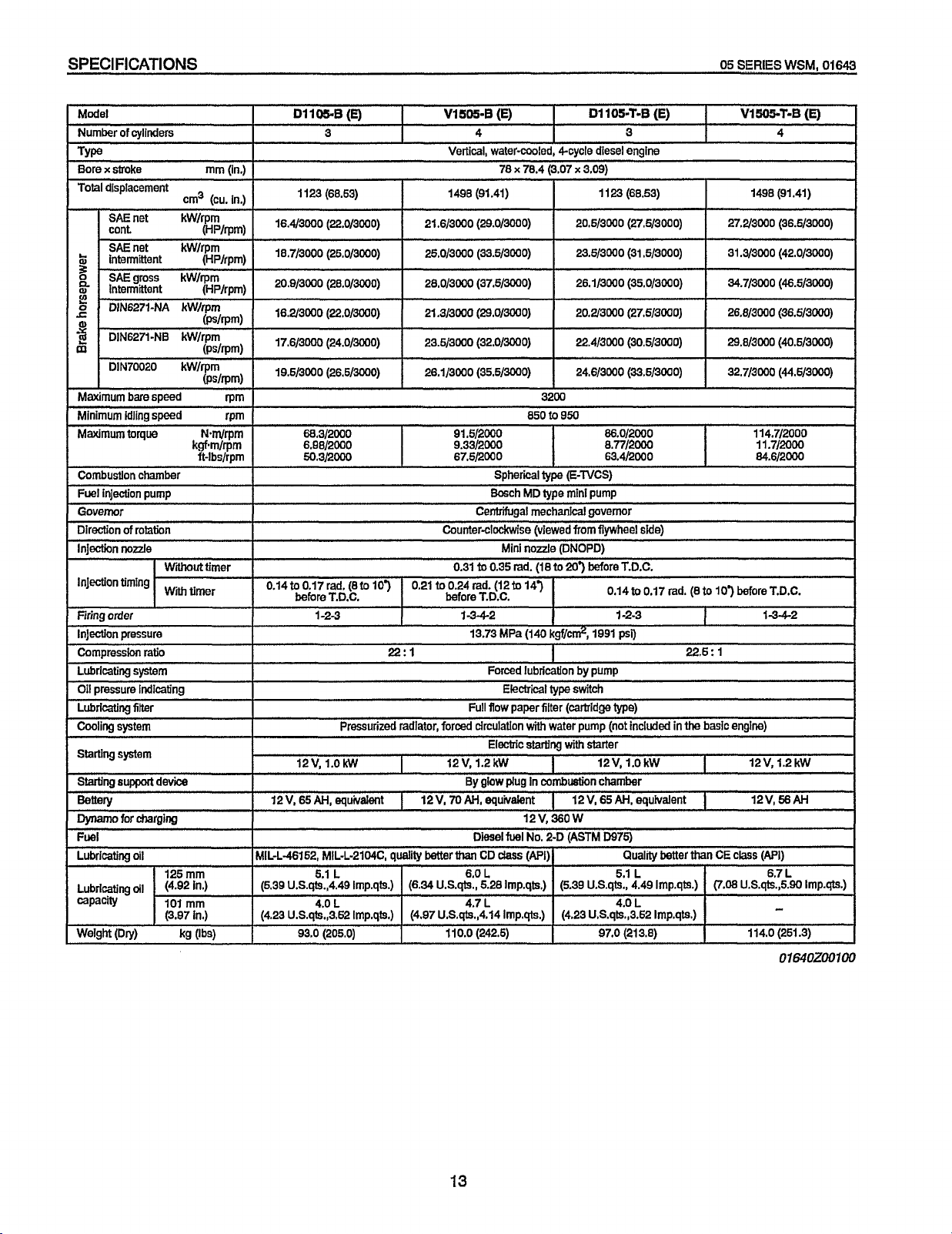
SPECIFICATIONS
Redistribution or publication of this document,
by any means, is strictly prohibited.
05
SERIES
WSM,
01643
Model
Number
of
cylinders
Type
I
Boraxstroke mm(in.)
Total displacement
SAEnet kW/rpm
cont
SAE
net kW/rpm
intermittent
SAE
gross kW/rpm
Intermittent (HPlrpm)
DIN6271-NA kW/rprn
DIN6271-NB kW/rpm (ps/rpm)
DIN70020 kW/rpm
Maximum
Minimum idling speed rPm
Maximum
I
Combustion chamber
Fuel injection pump
1
Governor Celllrifugal mechanical governor
Direction
Injection
Injection timing 0.14to0.17rad. (8tolO’) 0.21to0.24md. (12tol47
Firing order 1-2-3 1-342
lnjectlon pressure
Compression
Lubricating
Oil
Lubricating filter
Cooling
StarUng
Starting
bare speed
torque N-m/rpm
of
rotation
no&
system
pressure indicating
system
system
support
ratio
device
,1173
WNMut
W~
(cu. in.)
.I
(HP/rpm)
(Fdrpm)
kgf.m/rpm
ft-l
bshm
timer
timer
rpm
mmly
Dynamo
for charging 12v,360w
Fuel
Lubricating
Lubricating
capacity
WeW (Dry) kg
oll
125 mm
oll
(4.92
in-)
101
mrn
(3.97 in.) (4.23 U.S.qts,,3.52 Imp.qts.) (4.97 U.S.qts.,4.14 1mp.qts.) (4.23 U.S.qts.,3.52 Imp.qts.)
(W
D1105.B
I
1123 (68.53) 1498 (91.41)
I
16.4/3000
18.7/3000 (26.0/3000)
20.9/3000 (28.0/3000)
16.2/3000
17-6/3000 (24.0/3000) 23.5/3000 (32.0/3000) 22.4/3
I
I
I
I
before T.D.C. before T.D.C.
12v,
12 V,
65
MIL-L-46152, MlL-L-2104C, quality better
(5.39 U.S.qts.,4.49 Imp.qts.)
93.0 (205.0) 110.0 (242.5) 97.0 (213.8) 114.0 (251.3)
(E)
3
(22.0/3000)
(22.0/3000)
68.3/2000 91.5/20M) 86.0/2000
6.96/2000 9.33/2000
50.3/2000 67.5/2000 63.4/2000 84.6/2000
22:l
Pressurized radiator, forced circulation
1.okw
AH,
equivalent
5.1
L
4.0
L
Vl505-B
I
Vertical, water-cooled, 4-cycle diesel engine
I
21.6/3000 (29.0/3000) 20.5/3
25.0/3000 (33.5/3000) 23.5/3000 (31.5/3000)
28.0/3000 (37.5/3000)
21.3/300
I
Counter-clockwise (viewed
(E)
4
78 x 78.4 (3.07 x 3.09)
(29.0/3000)
850
SDherical
Bosch MD lype mini pump
Mini nozzle (DNOPD)
0.31
to
0.35 rad. (18
13.73 MPa
(140
D1105.T-B
I
1123 (68.53) 1498 (91.41)
26.1/3000
20.2/3000 (27.5/3000)
3200
to
950
I
tvm
E-TVCS)
..
.
from
flywheel
to
20’)
before T.D.C.
kgf/&,
1991
I
Forced lubrication by pump
Electrical
Full flow paper filter (midge
Electric
12 V, 1.2 kW 12V,
I
1
(6.34
By
glow
12V,
70
AH,
equivalent
Diesel
than
CD
dass
6.0
U.S.qts., 6.28 Imp.qts.) (5.39 U.S.qts., 4.49 Imp.qts.)
L 5.1
4.7 L 4.0
type
switch
with
water pump (not included
startlng
with
I
plug
in
combuetion chamber
I
12V, 65
fuel
No. 2-D
(ASTM
(Pi)
starter
(E)
3
00
0
(27.5/3000)
(35.0/3000)
000
(30.5/3000)
8.77/2000
side)
0.14to0.17 rad.
1
-2-3
psi)
type)
1.0
kW 12V, 1.2kW
AH,
equivalent
D975)
Quality better than
L
L
in
(8to
22.5:
the
I
1
10’)
I
1
basic engine)
I
I
CE
(7.08
Vl5a5-7-B
27.2/3000 (36.5/3000)
31.3/3000
34.7/3000
26.8/3000
29.8/3000
114.7/2000
11.7/2000
bef0reT.D.C.
12v,66AH
class
U.S.qts.,5.90 Imp.qts.)
4
(42.0/3000)
(46.5/WO)
(36.5/3000)
(40.5/3000)
1-342
(mi)
6.7
L
(E)
-
01640200100
I
I
13
Page 19
05
Redistribution or publication of this document,
by any means, is strictly prohibited.
SERIES
WSM,
01642
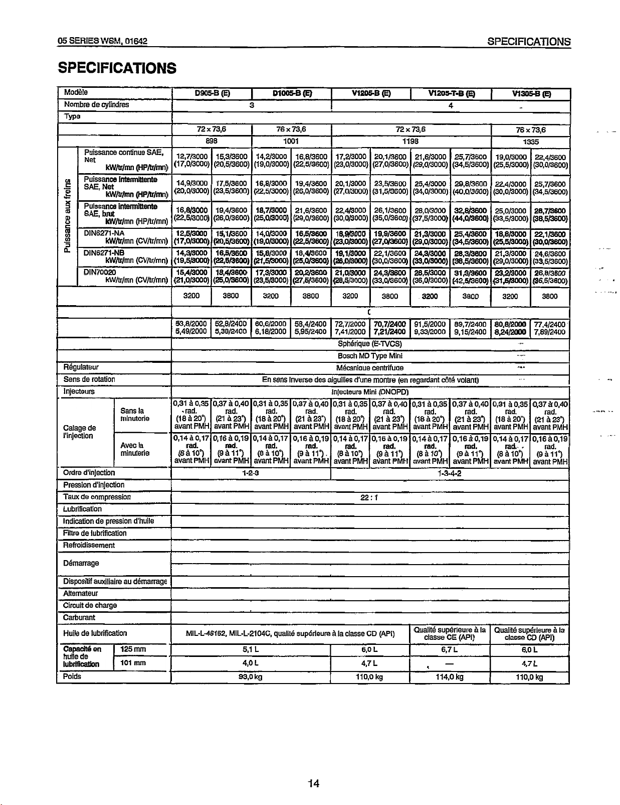
SPECIFICATIONS
SPECIFICATIONS
MoBle
Nombre de Cylindres
Twe
Puissance continue
Net
kW/tr/mn (HPh/rnn)
Puissance intennittente
S
SAE,Net
x
3
8
-
I
'
RBgulateur
Sens de rotation
lnjecteurs
Calage de
I'injection
Ordre d'injedon
Pression d'injection
Tam de compression
Lubrification
Indication de pression d'huile
Fibe de lubrification
Refroidissement
kW/tr/mn (HP/tr/rnn)
Puissance intennittente
SAE,
brut
kW/tr/mn (HP/tr/mn)
DIN6271-NA
kW/tr/mn (CV/tr/mn)
DIN6271-NB
kW/tr/mn (CV/tr/rnn)
DIN70020
kW/tr/mn (CV/tr/mn)
Sans
la
minuterie
Avec la
minutede
DWB
(E)
72 x 73.6 76 x 73,6
898
SAE,
12,7/3000 15,3/3600 14,2/3000 16,8/3600 17,2/3000 20,1/3600 21,6/3000 25,7/3600
(17,0/3000) (20,5/3600) (19,0/3000) (22,5/3600) (B,0/3000) (27,0/3600) (29,0/3000) (34,5/3600)
16,8/3000
(Z,5/3000)
12,5/3000
(17,0/3000)
14,3/3000
(19,5/3000)
15,4/3000
(21,0/3000)
3200
53,8/2000 52,8/2400
5,49/2000
~
0,31
*rad. rad. rad. rad. rad. rad. rad. rad. rad.
(18B20") (21 B23') (181209 (21 623') (18B207 (21 A237 (188207 (21 8237 (18B207
avant PMH avant PMH avant PMH avant PMH avant PMH avant PMH avant PMH avant PMH avant PMH
0,1480,17 0,16B0,19 0,1480,17 0,16B0,19 0,14B0,17 0,1680,19 0,1460,17 0,16B0,19 0,1480,17
(EA107
avant PMH avant PMH avant PMH avant PMH avant PMH avant PMH avant PMH avant PMH avant PMH
19,4/3600 18,7/3000 21,6/3600 22,4/3000 26,1/3600 28,0/3000 32,8/3600 25,0/3000 28,7/3600
(26,0/3600) (25,0/3000) (29,0/3600) (30,0/3000) (35,0/3600) (37,5/3000) (44.0/3600) (33,5/3000) (38,5/3600)
15,1/3600 14,0/3000 16,5/3600 16,9/3000 19,9/3600 21,3/3000 25,4/3600 18,8/3000 22,1/3600
(20,5/3600) (19,0/3000) (22,5/3600) (23,0/3000) (27,0/3600) (29,0/3000) (34,5/3600) (25,5/3000) (30,0/3600)
16,5/3600 15,8/3000 18,4/3600 19,1/3000 22,1/3600 24,3/3000 28,3/3600 21,3/3000 24,6/3600
(Z,5/3600) (21,5/3000) (25,0/3600) (26,0/3000) (30,0/3600) (33,0/3000) (38,5/3600) (29,0/3000) (33,5/3600)
18,4/3600 17,3/3000 20,2/3600 21,0/3000 24,3/3600 26,5/3000 31,3/3600 23,2/3000 26,8/3600
(25,0/3600) (23,5/3000) (27,5/3600) (28,5/3000) (33,0/3600) (36,0/3000) (42,5/3600) .(31,5/3000) (36,5/3600)
3800 3200 3800 3200 3800 3200 3800 3200
5,38/2400 6,18/2000
~ ~
BO,%
0,37B0,40 0,31
rad. rad. rad. rad. rad. rad.
(9B11')
D1005-B(E)-
I
3
1001
60,6/2000 58,4/2400 72,7/2000
En sens inverse des aiguilles d'une montre (en regardant c6t6 volant)
(8Bi0°)
1
-2-3
5,95/2400
BO,%
0,37B0,40 0,31 BO,35 0,37B0,40 0,31
(98117.
I
V1205-B
(E)
I
72
7,41/2000 7,21/2400
Spherique (E-Ncs)
Bosch MD Type Mini
M&anlOUR
lniecteurs Mini IDNOPD)
(8B107
70,7/2400 91,5/2000
centrifuae
(9811')
22:
1
I
W205-T-B(E)
x
73,6
1198
9,33/2000 9,15/2400
BO,%
rad. rad. rad.
(8B107
4
89,7/2400
0,3780,40 0,31 80,35
(9B117
1-3-4-2
I
W3w-B
19,0/3000 ~,4/3600
(25,5/3000) (30,0/3600)
80,8/2000 77,4/2400
8,24/2000 7,89/2400
(E)
76 x 73'6
1335
3800
-*.
-.
-.
.
0,37f0,40
rad.
(21 A237
avant PMH
0,16B0,19
,
(EA107
rad.
(98117
avant PMH
I
'
I
I
I
.-
I_
.
_..
-.
. . .
_._
.
-,
_....
.-
.
*.
,
DBmarrage
Dispos-tif auxiliaire au d6marmge
Altemateur
Circuit de charge
carburant
Huile de lubrification
huile de
Poids
MIL-L-46152, MlL-L-2104C, qU&B supedeure &la dasse CD
5.1
L
4,O L
93,O kg
~~
I
6,O
4,7
110,O
14
QualitB
(WI)
L
L
kg 114,O kg
supBrieure
classe CE
6,7
-
,
L
(API)
'
la
QualU
classe CD
su*rieure
6,O
L
4.7
L
110,O
(API)
kg
'la
Page 20
SPECIFICATIONS
Redistribution or publication of this document,
by any means, is strictly prohibited.
05
SERIES
WSM,
01643
Modhie
-
Nombre de cylindres
Type
AlBsaoe x course
I
Cyiindrk totale cm*
Puissance continue
SAE,
Net
kW/W/W/W/W/W/W/W/W/W/W/W/W/W/W/W/W/W/W/Wn
Puissance intermittente
2
Net
kW/lr/mn (HP/tr/mn)
Puissance intermittente SAE,
3
bNt
8
u1
u1
-
2
RBgime
RBaime
.,
Couple
Chambre de combustion
Pompe d'inlectlon
RBguiateur
Sens
lnjecteurs
Calage de
I'inJection
Ordre
Pression d'injection
Tam
Lubrification
indication de pression d'hulle
Fillre
Refroklissement
kWltrlmn (HP/tr/mn)
DIN6271-NA
kW/&/mn
DIN627I-NB
kW/lr/mn
DIN7020
kW/lr/mn (CV/&/mn)
maximum
minimum
maximum
..
de
rotation
d'injection
de compression
de lubrification
(HP/tr/mn)
(CVb/mn)
(CV/tr/mn)
B
vide trhn
B
vide
NaWlmn
(kgf.m/tr/rnn)
Sans
la
minuterie
Aveclamlnuten'e
m-ge
Dlsposttif
Altemamr
Circuit de charge
carburant
Huiie de IubrikationHuile
lubrffication
CapaMen
huh
librification
Polds
de
(A
six)
awiiialre
125rnm
101
au
dharrage
de
mm
D1105.B
mm
16,4/3000 (22,0/3000) 21,6/3000 (29,0/3000)
SAE,
trhn
18,7/3000 (25,0/3000)
20,0/3000 (28,0/3000) 28,0/3000 (37,5/3000) 26,1/3000 (35,013000) 34,713000 (46,5/3000)
16,2/3/3000
1716/3000
1g,5/3000
68,3/2000 01,5/2000 86,0/2000
6,06/2000 9,33/2000 8,77/2000 11,7/2OOO
0,14&0,17rad.
12 V, 1,0
12 V, 65
AH,
MIL-L46152, MlL-L-2104C,
(E)
3 4 3 4
1123
(22*0/3000)
(24*0/3000)
(2685/3000)
En
(8BlO')avant
PMH avant PMH
1
-2-3
22:
Radiateur
kW
ou
Bquivalent
sous
pression, circulation for&
quali
(W
5,l
L
4,O
L
93,O
kg
VISOS-B
Veacal,
25,0/3000
21,313000 (20,0/3000) 20,2/3000 (27,5/3000) 26,8/300 (36,513000)
23,5/3000 (32.0/3000) 22,4/3000 (30.6/3000) 29,8/3000 (40,5/3000)
26,1/3000 (35,5/3000) 24,6/3000 (33,5/33000) 32,7/3000 (44,5/3000)
sens
inverse
421
80,24md.
1
12V, 1,2
I I I
Par
bougie de prtkhauffage,
I
12 V, 70
suptkieure
(E)
B
refroldissement par eau, 4 temps,
78 x 78.4
1498 1123 1498
(33,5/3000) 23,5/3000 (31,5/3000) 31,3/3000 (42,0/3000)
3200
850
SpMrlque
Bosch
MD
MBcanique centrifuge
des
aiguilles d'une
Injecteun
h
0,35
rad.
MPa
Fode,
Par
contact
(18 B 20')
papler
0,31
(12B 143
1-342 1-2-3
13,73
Fiitre
BltSrnent
avec
DBmarreur Blectrique
kW
AH,
w
dquivalent
12v*38ow
GZOb
No
2-D
B
la
dasse
CD
6,O
L
4,7
L
110,O
kg
D1105-T-B
20,5/3WO (27,5/3000) 27,2/3000 (36,5/3000)
B
950
(E-WCS)
Type
Mini
montre
(en regardant
Mini
(DNOPD)
avant PMH
0,14
(E)
Diesel
B
0,17
cBt6
rad.
volant)
(8
B
V1505-T-B
103
avant
I
(140
kgf/cm2)
I
par pompe
Blectrlque
(type
cartouche)
pompe B eau (non compris dans
12v.
1,Okw
daw
la
chambre
de
I
12 V, 65
AH,
ou
(ASTM
DO76)
Qualit6
6,l L 6,7
4,O
L
07,O
kg
22,5:
mmbustlon
BqUiValent
superleure
1
le
moteur de base)
I
B
la
ciasse
1
14,7/2(100
PMH
1-342
12V,
12v,
CE
114,O
(E)
1
1,2kW
66AH
(API)
L
kg
15
Page 21
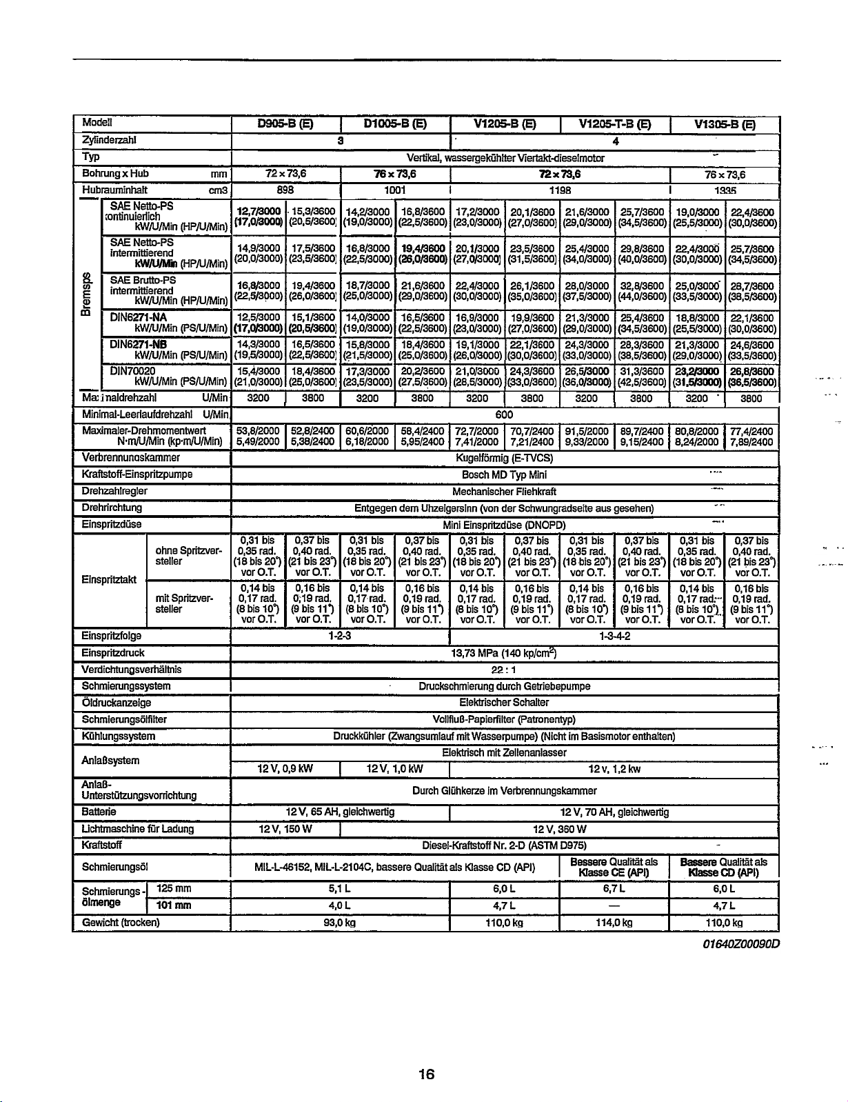
Modell
Redistribution or publication of this document,
by any means, is strictly prohibited.
Zyfinderzahl
TYP
x
Bohrung
Hubmuminhalt
-
v)
P
E
!!!
m
-
Ma:
Minimal-Leerlaufdrehhl
Maximaier-Drehmomentwert
Verbrennunoskammer
Kraftstoff-Einspritzpumpe
Drehzahlregler
Drehrirchtung
Einspriizdiise
Einspritztakt
Einspriilge
Einspriidruck
Verdichtunosverhiiltnis
Schmierungssystem
Oldruckanzeige
Schmierungsiilfilter
Whlungssystem
AnlaBsystem
AnlaD-
UnterstirturnasvorrichtunQ
Batterie
Uchtmaschine
mtoff
SchmierungsBI
Sctunierungs
iilmenge 101
Gewicht
Hub
SAE
Netto-PS
iontinuierlich
kWN/Min (HPN/Min)
SAE
Netto-PS
interm-tb'erend
kWRUMin
SAE
BNtto-PS
intermittierend
kWN/Min
DIN6271-NA
kWN/Min (PSN/Min)
DIN6271-NB
kW/U/Min (PSNIMin)
DIN70020
kWN/Min (PSN/Min)
naldrehzahl
NmAJiMin
ohne Spritzversteller
mitSpritzversteller
..
- -
filr
-
1%
(trocken)
(kpmNIMin)
Ladung 12V, 150
mm
cm3
(HPN/Min)
(HPN/Min)
U/Min
U/Min
mm
mm
-Bo
72
x
73,6
898
12,7/3000 .15,3/3600
(17,0/3000) (20,5/36W:
14,913000 17,5/3600
(20,0/3000) (23,5/3600]
16,8/3000 19,4/3600
*
(22,5/3000) (26,0/3600]
~
(17,0/3000) (20,5/3600]
3200
I
I I
53,8/2000 52,8/2400
5,49/2000 5,38/2400
0,31
bis
0,35
(18
bis
vor0.T. vor0.T.
0,14
0,17rad.
(8
bis
vor0.T. vor0.T.
I
0,37
rad.
0,40
207
(21
bis
0,16
0;lSrad. 0,17rad.
107 (9 bis
I
I
12 V, 0,9
I
I
I
I
I
I
I
12V,
MIL-L-46152, MlL-L-2104C,
I
DlSB(E)
3
Vwtikal,
76 x 73,6
I
3800 3200
bis
rad.
bis
237 (18
bis
113
1
-2-3 1-3-4-2
Druckkfihler (Zwangsumlauf
kW
I
I
65
AH,
gleichwertig
W
I
5,l
4.0
93'0 kg 1140 kg 114,O kg 110,O kg
1
w1
14,2/3000
(I
9,0/3000)
16,8/3000
(22,5/3000)
18,7/3000
(25,0/3000)
14,0/3000
(19,0/3000)
15,8/3000
(21,5/3000)
17,3/3000
(23,SMOOO)
60,6/2000
6,18/2000 5,95/2400
Entgegen dem Uhzeigersinn (von der Schwungradseite aus gesehen)
0,31
0.35 rad.
bis
vor0.T. vor0.T.
0,14 bis
(8
bis
vor0.T. vor0.T.
L
L
16,8/3WO 17,2/3000
(22,5/3600)
19,4/3600 20,1/3000
(26,0/3600)
21,6/3600 22,43000
(29,0/36OO)
3800
58,4/2400 72,7/2000
bis
0,37
0,40
207
(21 bis 237
0,16
0,19rad. 0,17rad.
107 (9
bis
Druckschmierung durch Getriebepumpe
12V, 1,0
bassere
kW
Durch Glirhkerze
Qualiit
bis
rad.
bis
113
VollfluD-Papierfilter (Patmnenlyp)
Diesel-KmfIstoff
V1205-B(E)
wassergektihlterviertaktdieselmotor
I
'
20,1/3600
~
I
(23,0/3000]
I
(27,0/3000]
I
(30,0/3000]
I
3200 3800
I
7,41/2000
Kuoelf6rmio
Bosch
Mechanischer Fliehkraft
(27,0/3600]
23.5/3600
(31,5/36001
26,1/3600
(35,0/3600]
22,1/3600
(30,0/3600)
24,3/3600
(33,0/3600)
I
600
70,7/aoo 91,5/2000 89,7/mo 80,8/2000 n,4/2m
7,21/2400 9,33/2000
(E-TVCSI
MD
Typ
I
VlPW-T-B(E)
4
72 x 73,6
1198
26,5/3000 31,3/3600 23,2/3000 26,8/3600
(36,0/3000)
I
Mini
3200
I
(42,5/36OO) I(31,5/3OOO) 1 (36,5/36W)
..
I
I
9,15/2400 8,24/2000
3800
1
I
..
I
I
3200
V1305-B
-
76 x 73.6
1%
..
*I
I
.I-
--.
.-
Mini
Einspwdiise (DNOPD)
0,31 bis 0,37
0,35
rad.
(18
bis
207
vor0.T. vor0.T. vor0.T. vor0.T. vor0.T. vor0.T.
0,14
bis
(8
bis
107
vor0.T. vor0.T. vor0.T. vor0.T.
13,73 MPa
=:I
__
EleMrischer Schalter
mit
Wasserpumpe) (NicM
Elekbisch
mit
I
1
im
I
Nr.
als
Masse
6.0
4.7
bis
12
237
bis
11')
V,
(18
12
360
I
0,31 bis 0,37
rad.
(21
bis
20')
0,14 bis 0,16
(8
bis
10') (9
im
Basismotor enttalten)
i2v, 1,2kw
V,
70
AH,
gleichwerlig
W
Qualiiak
Masse
CE
6,7
L
-
0,40 rad. 0,35
bis
(21
0,16
0,lSrad. 0,17rad. 0,19rad.
(9
bis
(140
kp/cn?)
Zellenanlasser
Verbrennungskammer
2-D (ASTM D975)
CD
(AH)
L
L
bis
0,40
rad.
bis
237 (18
bis
bis
117
I
[API)
.. ..
I..
0,31
bis
0,35
rad.
bis
207 (21
0,14
bis
0,17rad:-- 0,19rad.
(8
bis
10')- (9
vor0.T. vor0.T.
Qualiit
Masse
CD
6,O
4.7
(E)
3800
7,89/2400
0,37
bis
0,40
rad.
bis
237
0,16
bis
bis
117
*
(API)
L
L
I
I
1
.--
..
..--
-_
.._
.
1
..
.
16
Page 22
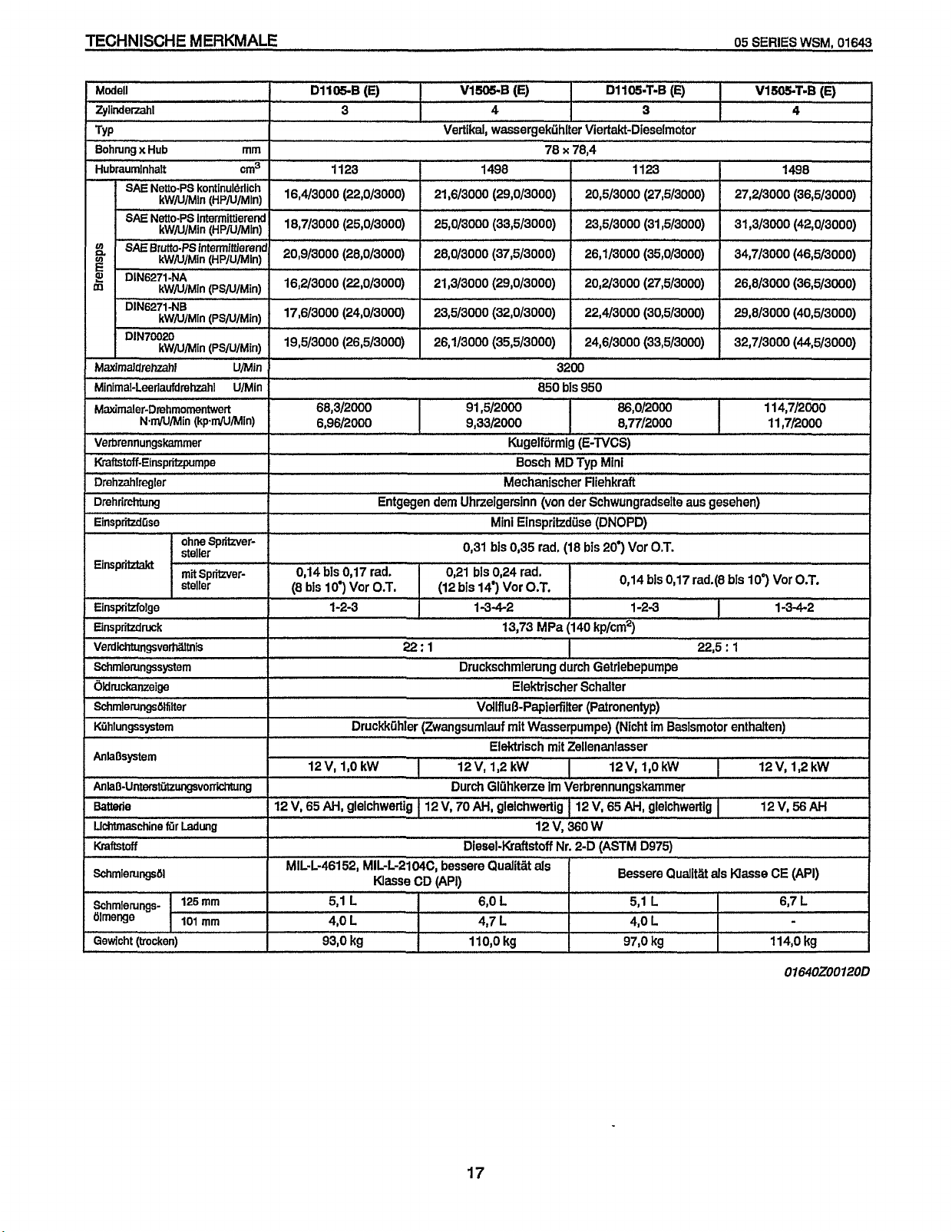
TECHNISCHE
Redistribution or publication of this document,
by any means, is strictly prohibited.
MERKMALE
05
SERIES
WSM,
01643
Modell
Zylindernl
TYP
BohNng
x
Hub
Hubraumlnhalt
SAE
Netto-PS kontinul&lich
kwjJmin (~p/~n\nl~)
mm
cm3
N~~~l~~~~~~~
#
sAEB~~~~~l',"~~~~$d
E
E
DIN6271-NA
D
Maximaldrehzahl
Minimal-Leedaufdrehhl U/Mln
Maximaler-Drehmornentwetwert
Verbrennungskammer
I
Kraftstoff-ElnsurilzrJurnoe
Drehzahlregler
DrehrircMung
Einspritzdlise Mini Elnspritzdilse (DNOPD)
Elnspriktakt
Elns~ritzfolae
Unspritzdruck
VerdicMungsverMlmis
Schmierungssystem
I
i)klruckanzeioe
SchmlerungsiSKtter
Kiihlungssystem
AnhOsystem
AnlaO-UnkdiIzungsvoterstirhung
Battecie
Uchtmaschine
Kraftstoff
~chrnienrngsi~~
Schmlerungs-
Blmenge
Gewicht (trocken)
kWN/Min (ps~/~i~)
DIN6271-NB
kwjJ/Min (PSN/M~~)
DIN70020
kwm/Min (pSm/Min)
U/Min
Nm/U/Min (kpnW/Min)
ohne Spritzversteller
mit
Spritzver-
steller
fijr
Ladung
12s
mm
101
mm
DllO5-B
16,4/3000 (22,0/3000) 21,6/3000 (29,0/3000) 20,5/3000 (27,5/3000) 27,2/3000 (36,5/3000)
18,7/3000 (25,0/3000)
20,9/3000 (28,0/3000)
16,2/3000 (22,0/3000)
17,6/3000 (24,0/3000)
19,5/3000 (26,5/3000)
I
I
68,3/2000 91,5/2000 86,0/2000 114,7/2000
6,96/2000 9,3312000 8,77/2000 11,7/2000
I
I
I
0,14 bis 0'17 rad.
(8
bis
I
12V,
12 V, 65
MIL-L-46152, MIL-L-21
(E)
3
1123 1498 1123 1498
Entgegen dem Uhrzeigersinn (von der Schwungradselte aus nesehen)
--
IO')
Vor
O.T.
1-2-3 1-3-4-2
22:
Druckklihler (Zwangsumiauf mit Wasserpumpe) (Nicht
1,0
kW
AH,
glelchwertig I 12 V, 70
MC,
Masse
CD lAPll
5,l L
4,O L
93,O kg
VI-B
Vertikal, wassergekuhlter Viertakt-Dieselmotor
25,0/3000 (33,5/3000)
28,0/3000 (37,5/3000)
21,3/3000 (29i0/3000)
23,5/3000 (32,0/3000)
26,1/3000 (35,5/3000)
0,31 bis 0,355
0,21 bis 0,24 rad.
(12 bls
1
Druckschrnierung durch Getriebepumpe
I
12V,
Durch Glahkerze
Diesel-Kraftstoff
bessere
(E)
4
78 x 78,4
3200
850 bis 950
Kugelformig
Bosch MD TVD Mini
Mechanischer Hiehkraft
-
rad.
143
Vor
O.T.
13,73 MPa
D1105-7-8
23,5/3000 (31,5/3000) 31,3/3OOO (42,0/3000)
26,1/3000 (35,0/3000) 34,7/3000 (46,5/3000)
20,2/3000 (27H3000) 26,8/3000 (36,5/3000)
22,4/3000 (30,5/3000) 29,8/3000 (40,5/3000)
24,6/3000 (33,5/3000) 32,7/3000 (44,5/3000)
(E-WCS)
-
(I8
bis 20') Vor
0,14
1
(1
40 kp/cm2)
I
Elektrischer Schalter
Vdlflut3-Papierfilter (Patronentyp)
Elektrisch mit Zellenanlasser
1,2 kW
AH,
gleichwertig I 12 V, 65
Qualitt
6,O L 5,l L 6,7 L
4,7 L
110,O
kg 97,O kg 114,O kg
I
12V,
im
Verbrennungskammer
12
v,
360
w
Nr. 2-D
(ASTM D975)
als
AH,
Bessere Qualitiit
4,O
(E)
3
-
O.T.
bis 0,17 rad.@ bis
-2-3
22,5
im
Basismotor enthatten)
1,O
kW
glelchwertig
als
L
I
:
I
I
Masse
1
Vl!SST-B
IO')
12 VI 1'2 kW
12v,56AH
Vor
1-3-4-2
CE
(API)
(E)
4
I
I
O.T.
I
016402001200
17
Page 23
05
Redistribution or publication of this document,
by any means, is strictly prohibited.
SERIES
WSM.
01640
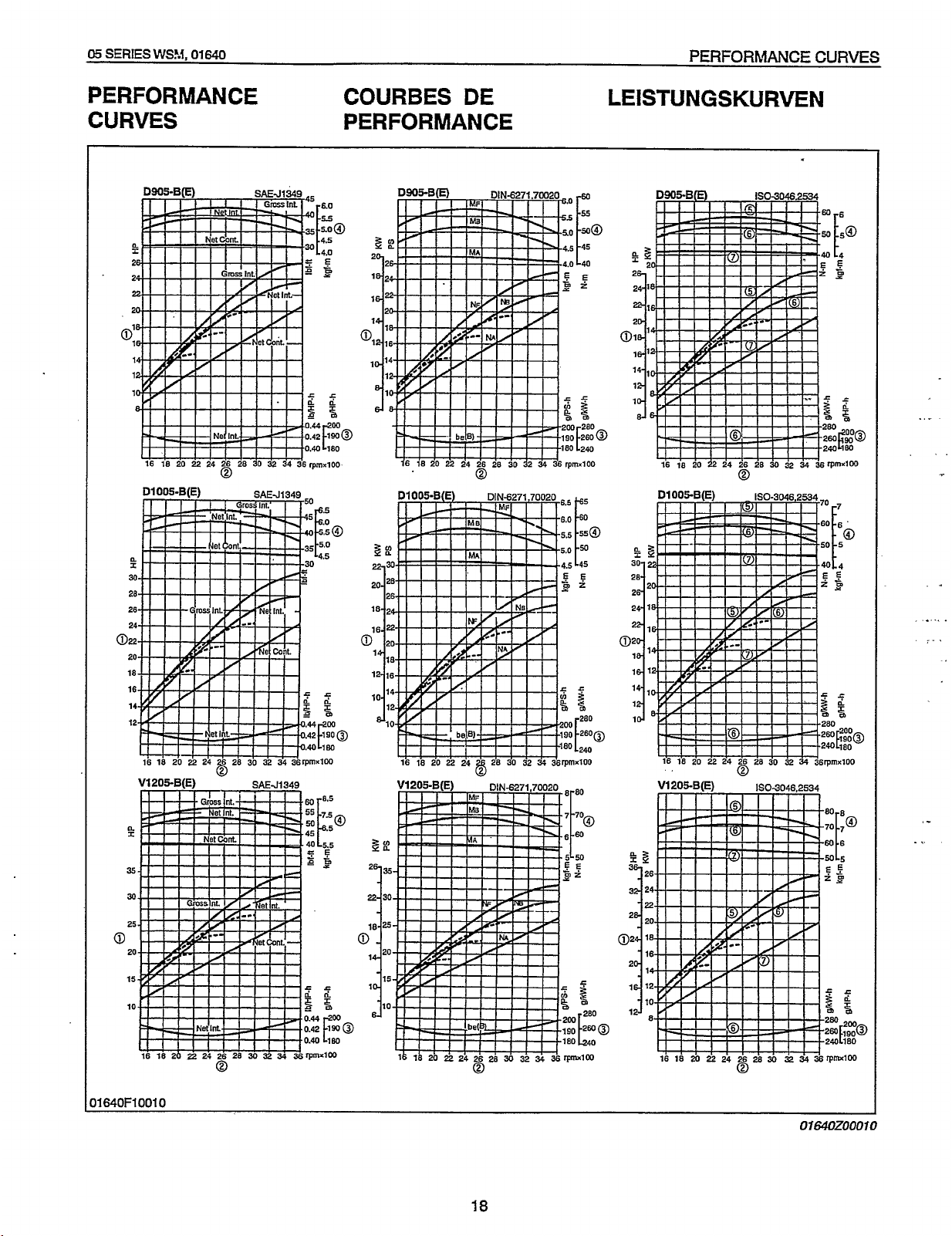
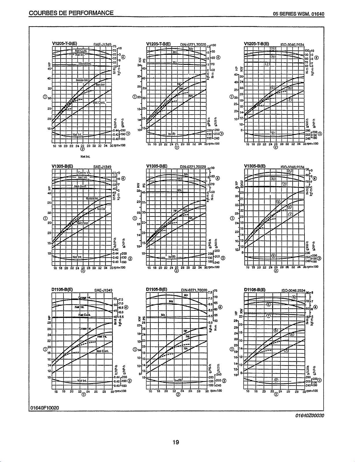
PERFORMANCE
CURVES
PERFORMANCE CURVES
COURBES
DE
PERFORMANCE
LEISTUNGSKURVEN
DSOOCB(E)
n
I
1803046.2534
..r
.
..
7
.I
(....
_I.
,-
.
1640F10010
ormozoooio
18
Page 24
COURBES
Redistribution or publication of this document,
by any means, is strictly prohibited.
0
DE
PERFORMANCE
05
SERIES
16
18
20
22
21
“F
t
WSM,
01640
20
30
32
34
36rnXlW
DllOS.B(E)
SAEJ134!
0
‘0.40
LlOO
)rpnxIW
19
01
6.10200020
Page 25
05
Redistribution or publication of this document,
by any means, is strictly prohibited.
SERIES
WSM,
01
642
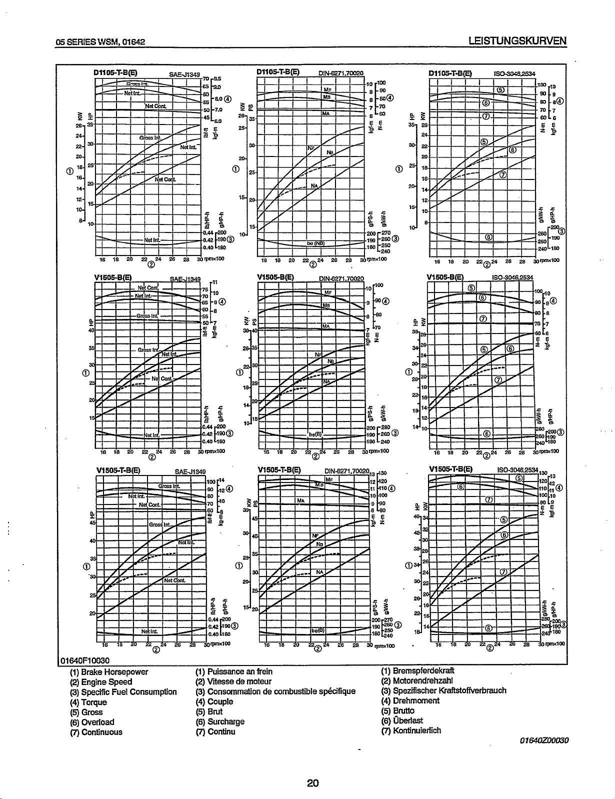
LEISTUNGSKURVEN
V1505B(E)
ST-B(E)
V1
SAF-J
,I%?
SAEJ1349
rll
VlSOCB(E)
DIN6271.70020
---
3164OF10030
(1) Brake Horsepower (1)
(2)
Engine Speed
(3) Specific Fuel Consumption
(4)
Torque
(5)
Gross
(6)
Overload
(7)
continuous
Puissance
(2)
Viiesse de moteur
an
frein (1) Bremspferdekraft
(3) Consommation de combustible spkifique
(4)
Couple
(5)
Brut
(6)
Surcharge
(7)
Continu
20
(2)
Motorendrehzahl
(3)
Spezifischer Kraftstofiierbrauch
(4)
Drehmoment
(5)
Brutto
(6)
uberlast
(7)
Kontinuierlich
Page 26
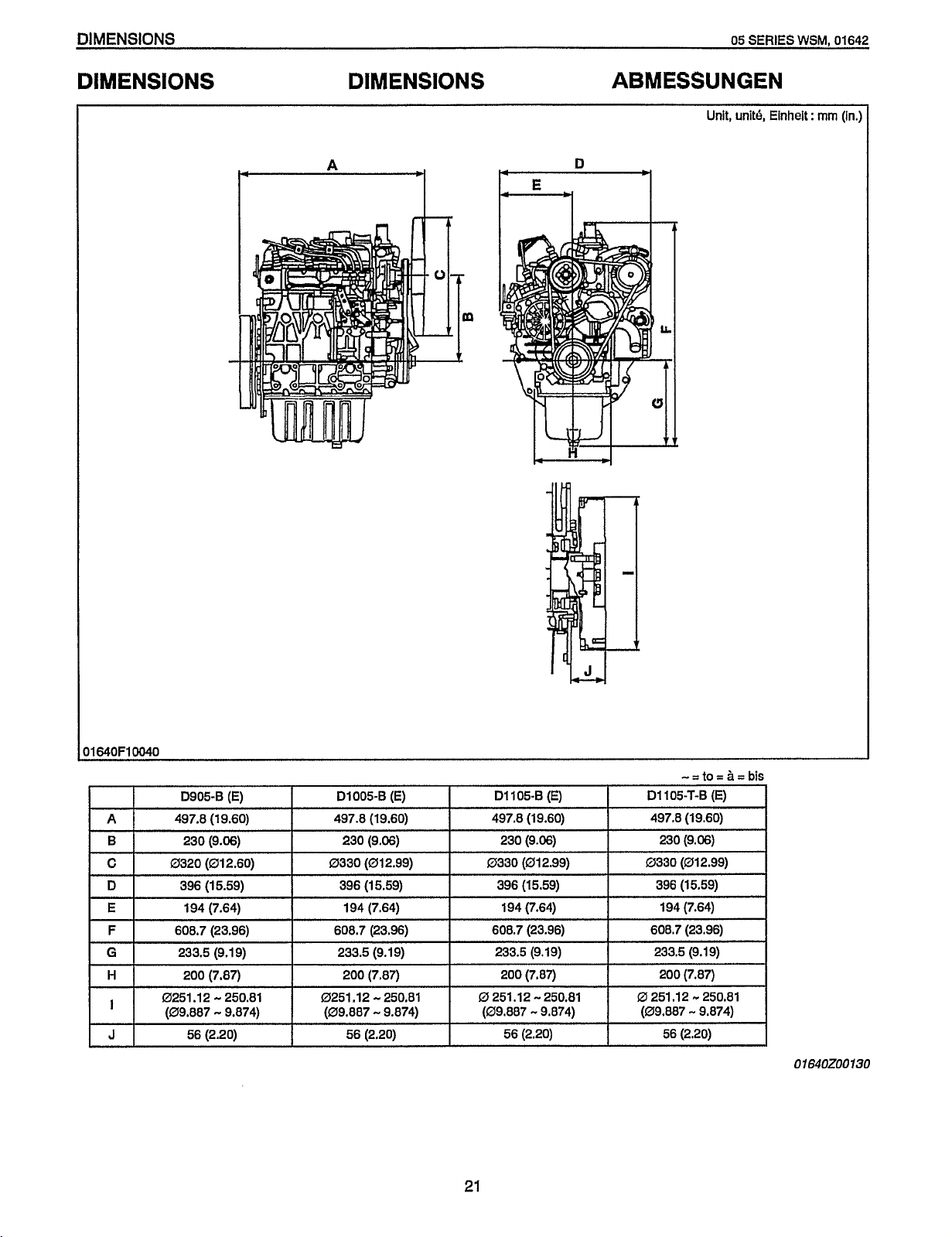
DIMENSIONS
Redistribution or publication of this document,
by any means, is strictly prohibited.
05
SERIES
DIMENSIONS DIMENSIONS ABMESSUNGEN
WSM,
01642
Unit, unit4 Einheit
:
mm
(in.)
I II
D905-6 (E) D1005-6
61
D
E
F
G
H
I
JI
230 (9.06)
396
(1
5.59) 396 (15.59) 396 (15.59) 396 (15.59)
194 (7.64) 194 (7.64) 194 (7.64) 194 (7.64)
608.7 (23.96)
233.5 (9.19)
200 (7.87)
-
0251.12
(09.887
250.81
-
9.874)
56 (2.20)
I
608.7 (23.96) 608.7 (23.96) 608.7 (23.96)
233.5 (9.19) 233.5 (9.19) 233.5 (9.19)
0251
(09.887
(E)
230 (9.06) 230 (9.06) 230 (9.06)
200 (7.87) 200 (7.87)
.I2
-
250.81
-
9.874) (09.887 - 9.874) (09.887 - 9.874)
56
(2.20) 56 (2.20) 56 (2.20)
D1105-B (E) D1105-T-6
0
251.12
.-.
250.81
21
200 (7.87)
0
251.12 - 250.81
(E)
01640200130
Page 27
05
Redistribution or publication of this document,
by any means, is strictly prohibited.
SERIES
J”JSk4,
01640
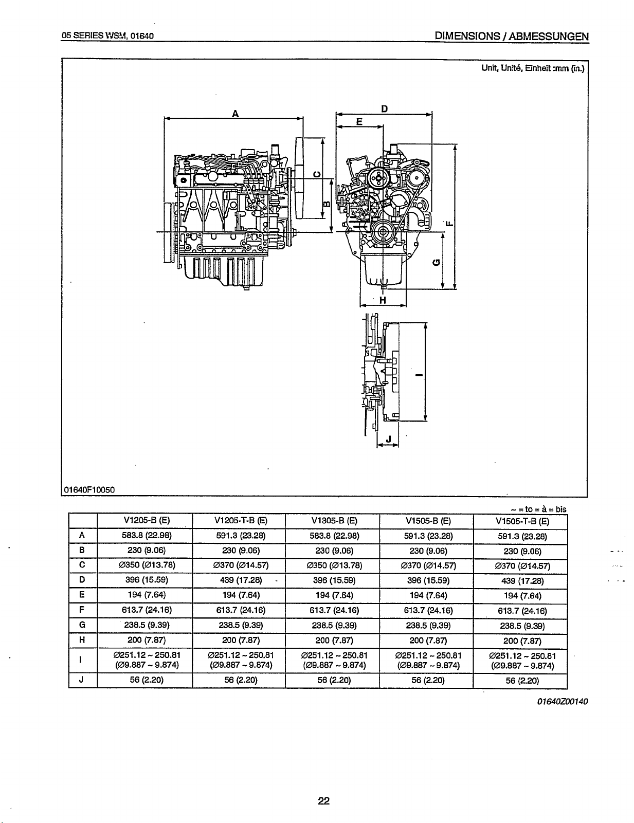
DIMENSIONS / ABhjESSUNGEN
Unit,
Unite,
Einhekmm
(in.]
11
640F10050
A
B
C
D
E
F
G
H
I
J
V1205-B
583.8 (22.98) 591.3 (23.28) 583.8 (22.98) 591.3 (23.28) 591.3 (2328)
230 (9.06) 230 (9.06)
0350 (013.78) 0370 (014.57) 0350 (013.78) 0370 (014.57) 0370 (014.57)
396 (15.59) 439 (17.28)
194 (7.64) 194 (7.64)
613.7 (24.16) 613.7 (24.16) 613.7 (24.16)
238.5 (9.39)
200 (7.87) 200 (7.87)
0251.12
(09.887
(E)
-
250.81
-
9.874) (09.887 - 9.874) (09.887 - 9.874)
56 (2.20) 56 (2.20) 56 (2.20) 56 (2.20)
V1205-T-B
238.5 (9.39) 238.5 (9.39)
0251.12
(E)
-
-
250.81 0251.12 - 250.81
V1305-8
230 (9.06) 230 (9.06) 230 (9.06)
396 (15.59) 396 (15.59) 439 (17.28)
200 (7.87) 200 (7.87) 200 (7.87)
(E)
194 (7.64) 194 (7.64) 194 (7.64)
V1505-B
613.7 (24.16) 613.7 (24.16)
238.5 (9.39) 238.5 (9.39)
0251.12
(09.887
(E)
-
250.81 0251.12 - 250.81
-
9.874) (09.887 - 9.874)
V1505-T-B
56 (2.20)
(E)
01640200140
22
Page 28

Redistribution or publication of this document,
by any means, is strictly prohibited.
Page 29

CONTENTS
Redistribution or publication of this document,
by any means, is strictly prohibited.
131
FEATURE ......................................................................................................... M-I
ENGINE BODY
[I]
CYLINDER BLOCK
[2] CYLINDER HEAD
[3] CRANKSHAFT
[4] PISTON AND PISTON RINGS
[5] CONNECTING ROD
[6] ROCKER ARM
CAMSHAFT
[SI
FUEL CAMSHAFT
[9] FLYWHEEL
LUBRICATING SYSTEM
[I]
GENERAL
[2] OIL PUMP
[3] RELIEF VALVE
[4] OIL FILTER CARTRIDGE
[5] OIL PRESSURE SWITCH
EI
COOLING SYSTEM
[I]
GENERAL
21 WATER PUMP
[3] THERMOSTAT
[4] RADIATOR (nothluded in the basic engine)
[5] RADIATOR CAP
INTAKE
.[I]
[2] MUFFLER (not included in the basic engine)
H
FUEL SYSTEM
[I]
[2] INJECTION PUMP
[3] INJECTION NOZZLE
[4] FUEL FILTER (not included in the basic model)
[5] GOVERNOR
[SI
ELECTRICAL SYSTEM
[I]
TURBO CHARGER SYSTEM
/
AIR CLEANER (not included in the basic engine)
GENERAL
(1) Pump Element
(2) Delivery Valve
(3) Dumping Valve
(4) Injection Control
AUTOMATIC ADVANCE TIMER (not included in the basic model)
CHARGING SYSTEM
(1)
Alternator
(2) IC Regulator
(1) Mechanism .......................................................................................... M-45
(2)
Turbine ................................................................................................ M-47
(3)
Compressor
(4)
Bearing
(5)
Seals (Piston Rings)
................................................................................................
...................................................................................
......................................................................................
...........................................................................................
................................................................
..................................................................................
..........................................................................................
................................................................................................
.....................................................................................
................................................................................................
...............................................................................
.................................................................................................
................................................................................................
........................................................................................
......................................................................
......................................................................
......................................................................................
.................................................................................................
.........
1
..............................................................................
.........................................................................................
........................................
......................................................................................
EXHAUST SYSTEM
.....................................................................
..................................
................................
..............................................................................................
.................................................................................................
..................................................................................
.....................................................................................
.....................................................................................
....................................................................................
..................................................................................
...............................................................................
....................................
.............................................................................................
..................................................................................
..............................................................................
?
.................................................................
........................................................................................
......................................................................
.........................................................................................
................................................................................................
...............................
...........................................
...........................
:
......... M-23
......
M-3
M-3
M-3
M-5
M-5
M-7’
M-7 .
M-7
M-9
M-9
M-11
M-11
M-13
M-13
M-15
M-15
M-17
M-17
M-17
M-I 9
M-39
M-21
M-23
M-23
M-25
M-25
M.25
M-27
M-27
M-29
M-29
M-31
M-31
M-33
M-37
M-41
M-41
M-41
M-41
M-43
M47
M-49
M-51
Page 30
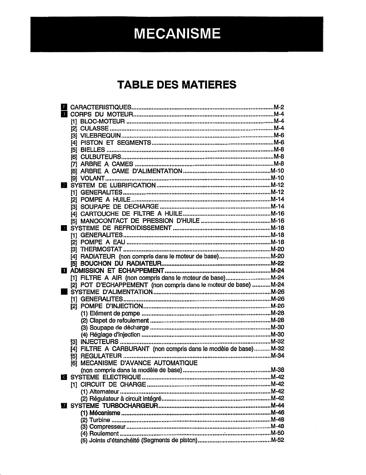
TABLE DES MATIERES
Redistribution or publication of this document,
by any means, is strictly prohibited.
CARACTERISTIQUES
CORPS DU MOTEUR
[I] BLOC-MOTEUR
[2] CULASSE
[3] VlLEBREQUlN
[4] PISTON ET SEGMENTS
[5] BIELLES
[6] CULBUTEURS.,
m
ARBRE A CAMES
[8] ARBRE A CAME D’ALIMENTATION
[9] VOLANT
L11
SYSTEM DE LUBRlFlCATlON
[I]
GENERALITES
[2] POMPE A HUlLE
[3] SOUPAPE DE DECHARGE
[4] CARTOUCHE DE FILTRE A HUILE
[SI
MANOCONTACT DE PRESSION D’HUILE
SYSTEME DE REFROIDISSEMENT
[I]
GENERALITES
[2] POMPE A EAU
[3] THERMOSTAT
[4] RADIATEUR (non compris dans le moteur de base)
[5]
BOUCHON DU RADIATEUR
El
ADMISSION ET ECHAPPEMENT
[I]
FILTRE
[2] POT DECHAPPEMENT (non compris dans le moteur de base)
SYSTEME DALIMENTATION
[l]
GENERALITES
[2] POMPE DINJECTION
(1)
Element de pompe
(2) Clapet de refoulement
(3)
Soupape de decharge
(4)
R6glage d’injection
[3] INJECTEURS
[4] FILTRE A CARBURANT (non compris dans le modhle de base)
[5] REGULATEUR
[6] MECANISME DAVANCE AUTOMATIQUE
(non compris dans la modhle de base)
IEl
SYSTEME ELECTRIQUE
[I]
CIRCUIT DE CHARGE
(1)
Alternateur
(2) R6gulateur & circuit integi-6.
111
SYSTEME TURBOCHARGEUR
(1)
Mecanisme
(2) Turbine
(3)
Compresseur
(4) Roulement
(5)
Joints
...................................................................................................
.....................................................................................................
....................................................................................................
A
AIR
................................................................................................
d’t5tanch6it6 (Segments de piston)
......................................................................................
.....................................................................................
.........................................................................................
............................................................................................
..........................................................................
..........................................................................................
....................................................................................
.....................................................
.....................................................................
.........................................................................................
....................................................................................
...................................................................
.....................................................
..........................................
...........................................................
.........................................................................................
.......................................................................................
.........................................................................................
...............................
..................................................................
................................................................
(non compris dans le moteur de base)
...........................
.......................................................................
.........................................................................................
.............................................................................
..............................................................................
.........................................................................
.........................................................................
..............................................................................
...........................................................................................
.........................................................................................
.....................................................
..............................................................................
...........................................................................
...........................................................................................
.................................................................
....................................................................
..........................................................................................
.......................................................................................
...............................................................
;
...........................
............................................
...........
..........
M-2
M-4
M-4
M-4
M-6
M-6
M-8
M-8
M-8
M-10
M-10
m-12
M-12
M-14
M-14
M-16
M-16
M-18
M-18
M-18
M-20
M-20
M-22
M-24
M-24
M-24
M-26
M-26
M-26
M-28
M-28
M-30
M-30
M-32
M-32
M-34
M.38
M-42
M-42
M-42
M-42
M-44
M.46
M.48
M-48
M-50
M-52
Page 31

VERZEICHNIS
Redistribution or publication of this document,
by any means, is strictly prohibited.
131
MERKMALE
MOTORKORPER
[I]
ZYLINDERBLOCK
[2] ZYLINDERKOPF
[3] KURBELWELLE
[4] KOLBEN UND KOLBENRINGE
[5] PLEUELSTANGE
[6]
KIPPHEBEL
m
NOCKENWELLE
[8] KRAFTSTOFF-NOCKENWELLE
[9]
SCHWUNGRAD
H
SCHMIERUNGSSYSTEM
[I]
ALLGEMEINES
121
OLPUMPE
131 UBERDRUCKVENTIL
[4]
OLFILTERPATRONE
[5] OLDRUCKSCHALTER
K~HLUNGSSYSTEM
[I]
ALLGEMEINES
[2] WASSERPUMPE
[3] THERMOSTAT
[4] KUHLER (nicht im Basismotor enthalten)
[5] KUHLERVERSCHLUSSKAPPE
H
ANSAUG-UND AUSPUFFSYSTEM
[I]
LUFTRILTER (nicht im Basismotor enthalten)
[2] AUSPUFFTOPF (nicht im Basismotor enthalten)
KRAFTSTOFF-SYSTEM
[I]
ALLGEMEINES
[2] EINSPRITZPUMPE
(1)
(2) Druckventil
(3)
(4) Einspritzregelung
[3] EINSPRITZDUSE
[4] KRAFTSTOFFFILTER (nicht im Basismodell enthalten)
[5] DREHZAHLREGLER
[6]
AUTOMATISCHER VERSTELLER
(nicht
H
ELEKTRISCHES SYSTEM
[I]
LADESYSTEM
(1)
(2) IC-Regulers
TURBOLADERSYSTEM
(1) Mechanik
(2) Turbine
(3) Kompressor
(4) Lager
(5)
.....
i
................................................................................................
.............................................................................................
......................................................................................
........................................................................................
.........................................................................................
...............................................................
.......................................................................................
................................................................................................
........................................................................................
.............................................................
.......................................................................................
.......................................... ! ...................................
........................................................................................
................................................................................................
..............................................................................
...............................................................................
.............................................................................
.....................................................................................
........................................................................................
.....................................................................................
............................
............................................................
................................................
...............................................................
..............................................................
........................................
................................................................................
........................................................................................
..................................................................................
Pumpenelement
..................................................................................
...........................................................................................
AblaSventil
...........................................................................................
.................................................................................
......................................................................................
................................................................................
im
Basismodell enthalten)
...............................................................
............................................................................
..........................................................................................
Wechselstromdynamo
.........................................................................
.........................................................................................
................................................................................
.............................................................................................
................................................................................................
.........................................................................................
...................................................................................................
Dichtringe (Kolbenringe)
......................................................................
....................................
.........................
M-2
M-4
M-4
M-4
M-6
M-6
M-8
M-8
M-8
M-I
0
M-IO
M-12
M-12
M-14
M-14
M-16
M-16
m-18
M-18
M-18
M-20
M-20
M-22
M-24
M-24
M-24
M-26
M-26
M-26
M-28
M-28
M-30
M-30
M-32
M-32
M-34
M-38
M-42
M-42
M-42
M-42
M-44
M-46
M-48
M-48
M-50
M-52
Page 32

DIESEL ENGINE
Redistribution or publication of this document,
by any means, is strictly prohibited.
131
FEATURE
05
The
05
SERIES
SERIES
ENGINE are vertical, water-cooled,
WSM,
01642
4
cycle diesel engines.
They are incorporated KUBOTA's foremost
technologies. With
Combustion System), well-known Bosch
injection
pump
KUBOTA's
E-TVCS (Three Vortex
MD
type
and the well-balanced designs, they give
greater power, low fuel consumption, little vibration and
quiet operation.
NOTE
0
Since January 1994, E-NCS has been used for
of
the combustion chamber
our products instead
of traditional N-NCS.
E-TVCS was developed with an eye toward clean
is
exhaust gas which
more environmentally
freindly.
The combustion chamber models mentioned
hereinafter refers to
Model of combustion chamber
E-TVCS.
:
N-TVCS
(Engine Serial Number
;
489290
or
lower)
E-TVCS
;
(Engine Serial Number
489291 or higher)
11640F10070
31640F10080
M-1
1
19OOM
1001
1
Page 33

05
Redistribution or publication of this document,
by any means, is strictly prohibited.
SEFUES
\"4SF.I,01642
MOTEUR
DIESEL
/
DIESELMOTOR
CARACTERISTIQUES
Les moteurs moteur (sene
&
4
diesel
par eau.
temps, a cylindres verticaux et refroidissement
Ils
b6neficient des technologies les
avancees de KUBOTA. Les
Combustion System) de KUBOTA, les pompes
&injection MD de Bosch type bien connues, et une
conception bien equilibree donnent
puissance accrue, une consommation tr&s basse, un
fable niveau de vibrations et un fonctionnement
silencieux.
1
NOTA
La chambre d'explosion, auparavant modele N-
NCS, des appareils produits depuis Janvier 1994
a
ete remplacee par le modele E-NCS, plus
ecologique et produisant des
moins polluants.
Le modele des chambres d'explosion suivantes
sera indique par E-NCS.
Modele de la chambre d'explosion
N-NCS
(Numero de serie
du
E-NCS
(Numero
de
serie du moteur; posterieur a 489291)
a
05)
sont des moteurs
plus
E-TVCS
(Three Vortex
a
ces moteurs une
gaz
d'echappement
:
moteur ; anterieur 5 489290)
MERKMALE
Bei den Motoren Serienmotor
urn vertikale, wassergekiihlte, ViertaktDieselmmotoren. Sie
Technologie WBOTAS ausgelegt. Mit der
(Three Vortex Combustion System) von KUBOTA, der
bekannten Einspritzpumpe
durchdachten, ausgewoggenen KonstruMion bieten sie
hohere Leistung, geringen Kraftstoffverbrauch sowie
vibrationsarmen und ruhigen
ANMERKUNG
0
In
allen ab
1.
Januar 1994 produzierten Anlagen
wurde der bisherige Brennkammertyp N-NCS
durch den neu entwickelten Typ E-NCS ersetzt,
der dank reinerer Abluft besonders
umweltfreundlich ist.
Die folgenden Beschreibungen beziehen sich auf
den Brennkammertype E-NCS.
Brennkammertyp:
N-TVCS
(Motorseriennummern 489290 und davor)
E-NCS
.
(Motorseriennummern 489291 und danach)
mit
05
handeft
sind
nach der neuesten
Das
Typ
MD von Bosch und der
Lad.
119OOM10011A
es
sich
E-TVCS
I
Page 34

DIESEL ENGINE
Redistribution or publication of this document,
by any means, is strictly prohibited.
05
SERIES
WSM,
01640
ENGINE
[I]
CYLINDER BLOCK
I
I
19OOF10020
l1900F10030
BODY
A
The engine has a high durability tunnel-type cylinder
block in which the crank bearing component is a
constructed body.
Furthermore, liner less type, allow effective cooling,
less distortion, and greater wear-resistance.
The noise level is reduced to a minimum because
each cylinder has its own chamber.
11900M10020
The cross-flow type intake / exhaust ports in this
engine have their openings at both sides of the cylinder
of
head. Because overlaps
smaller than in ports
of
intake / exhaust ports are
other types which have openings
on one side, the suction air can be protected from being
heated and expanded by heated exhaust air. The cool,
high density suction air has high volume efficiency and
of
raises the power
of
the cylinder head by heated exhaust gas is reduced
the engine. Furthermore, distortion
because intake ports are arranged alternately.
of
The combustion chamber is
E-TVCS
combustion chamber type. Suction air
KUBOTA's exclusive
is
whirled to be mixed effectively with fuel, prompting
combustion and reducing fuel consumption.
In the combustion chamber are installed throttle type
injection nozzle and rapid heating sheathed type glow
plug. This glow plug assures easier than ever engine
-15
'C
(5
starts even at
'0.
I
1790F10040
(1)
Combustion Chamber
(2)
Intake
(3)
(4)
(5)
(6)
Port
Exhaust
Nozzle
Glow
Cylinder Head
Port
Assembly
Plug Chamber
(7)
Depression
(8)
Compressed Air
(A)
Connect
to
Combustion
I
M-3
I
1790F10050
(4
1
1
QOOM 10031
Page 35

05
Redistribution or publication of this document,
by any means, is strictly prohibited.
SERIES
WS?.I,
01642
MOTEUR
DIESEL / DIESELMOTOR
CORPS
[I]
BLOC-MOTEUR
DU
MOTEUR
Le bloc-moteur est de type tunnel avec portees de
palier de vilebrequin integrees. Ce bloc-moteur, de type
-
sans-chemise, permet un refroidissement efficace,
reduit le risque de deformation, et ofFre une meilleure
a
resistance
I'usure; en outre, le fait que chaque cylindre
est dote de sa propre chambre contribue au silence de
fonctionnement du moteur.
[2]
CULASSE
Ce bloc-moteur comporte une culasse
transversal avec des lumieres d'admission
d'echappement disposees de part et d'autre. Ce type de
culasse minimise le chevauchement des orifices
d'admission et d'echappement par rapport
de culasse avec orifices situ& du mQme cote. Ainsi I'air
frais est aspire sans subir de modification de
a
temperature liee
la proximite de I'orifice
d'kchappement et permet d'augmenter la puissance du
moteur. De mQme cette disposition des lumieres de
minimiser les risques de deformation liees
La
temperature.
chambre de combustion est une
exclusivite KUBOTA (nouvelle chambre de combustion
E-TVCS). Lair frais aspire entre dans un zone de
turbulence et se melange efficacement avec le gazole
la
ameliorant ainsi
combustion et reduisant
consommation. La chambre de combustion comporte
des injecteurs et des bougies de prechauffage. Ces
a
bougies ameliorent le demarrage
pouvant descendre jusqu'a
Chambre de combustion
Lumihre d'admission
Lumigre d'kchappement
Ensemble injecteur
Bougie de prgchauffage
Culasse
-1
5
0
(8)
(A)
des temperatures
"C.
Dkpression
Air
comprimk
a
a
des types
.
a
[i]
MINDERBLOCK
Der Motor ist mit einem hochstabilen, tunnelarb'g
ausgelegten Zylinderblock ausgeriistet. AuBerdem
sorgen ohne Zylinderbuchen, Zylinderlaufbuchsen fijr
fijr
eine w'rksame Kiihlung sowie
eine verminderte
Verformung und eine hohere VerschlBifestigkeit. Da
jeden Zylinder eine eigene Kammer vorgesehen ist, wird
auf
die Liirmentwicklung
[2]
ZYLINDERKOPF
flux
et
Die in Querstromausfiihrung vorgesehenen Ein- und
AuslaRschlitze sind beiderseits des Zylinderkopfes
ein MindestmaB reduziert.
angeordnet. Da die Uberlappungen der Ein- und
AuslaBschlitze kleiner sind, als bei den Schlitzen
anderer Ausfijhrungen, die nur an einer Seite
vorgesehen sind, wird eine Erwarmung der angesaugten
Luft und eine Ausdehnung durch die erwarmten Abgase
vermieden. Die kuhle, hochdichte Ansaugluft tragt zu
einer Verst5rkung der Motorleistung bei. AuBerdem wird
die Gefahr einer Verformung des Zylinderkopfes durch
erwarmte Abgase eingeschrankt, da die
la
Ansaugoffnungen abwechselnd angeordnet sind. Die
Verbrenungskammer ist als Das neue E-TVCS, von
KUBOTA speziell entwickelte, Verbrennungskammer
ausgelegt. Die angesaugte Luft wird durchwirbelt und
la
sorgfaltig mit dem Kraftstoff vermischt, wodurch die
Verbrennung begunstigt und der Kraftstoffverbrauch
eingeschrankt wird.
In der Verbrennungskammer ist die mit einer
Drosselklappe versehene Einspritzduse und die
abgeschirmte, schnell heizende Gluhkerze
untergebracht. Diese Gluhkerze sorgt fur ein noch
schnelleres Anspringen des Motors, selbst bei
(3)
AuslaBkanal
(4)
Dusen
(5)
Gliihkerze
(6)
Zylinderkopf
(A)
Mit
Verbinden
dem Brennraum
fijr
7
1900M10020A
-15
"C.
119OOM10031A
h44
Page 36

DIESEL ENGINE 05 SERIES
Redistribution or publication of this document,
by any means, is strictly prohibited.
[3]
CRANKSHAFT
The crankshaft with the connecting rod converts the
of
reciprocating motion
the piston into the rotating
motion.
The crankshaft is made of tough special alloy steel,
and the journals, pins and oil seal sliding portions are
induction hardened to increase the hardness for higher
wear resistance.
a
The front journal is supported by
solid type bearing,
the intermediate journal by a split type, and the rear
journal by a split type with thrust bearings.
The crankshaft is provided with an oil gallery, through
which engine oil is fed to the crankpin portion, and
I1
790Fl
0060
[4]
PISTON AND PISTON
RINGS
lubricates it.
I
The piston has a slightly oval shape when cold (in
consideration of thermal expansion) and a concave
head.
Three rings are installed in grooves
(1)
The top ring
is a keystone type, which can stand
in
the piston.
against heavy loads, and the barrel face on the ring fits
well to the cylinder wall.
The second ring
(2) is an undercut type, which
effectively prevents the oil from being carried up.
(3)
The oil ring
has chamfered contact faces and an
expander ring, which increase the pressure of the oil ring
against the cylinder wall.
on
I179OF10070
Several grooves are cut
the top land to help heat
dissipate and to prevent scuffing.
(4)
(1)
TopRing
(2)
Second
(3)
Oil Ring
Ring
Depression
(5)
Valve
Recess
WSM,
1
I790M
01642
1OO40
I
1900FlOO40
1
M-5
1
1900M10041
Page 37

05
Redistribution or publication of this document,
by any means, is strictly prohibited.
SERIES
[3]
WSY,
01542
VILEBREQUIN
Le
vilebrequin trmsforme avec la bielle le
mouvement alternatif du piston en mowernent rotatif.
Le vilebrequin est en acier allie special et ses
extrernites, ses tourillons, et les zones de frottement
(joint d‘etancheite) sont trempees par induction
a
devenant ainsi plus resistantes
I’usure.
Cextrernite avant et chaque tourillon du vilebrequin
comportent un palier (demontable en deux demiparties). Cextrernite arriere du vilebrequin comporte
un
egalernent
palier de ce type avec des bagues but6e.
Le vilebrequin comporte une canalisation d’huile qui
perrnet la lubrification du tourillon.
[4]
PISTON ET SEGMENTS
MOTEUR
131
KURBELWELLE
DIESEL/
DIESELMOTOR
Die Kurbelwelle mit der Pleuelstange wandelt die
Hubkolbenbewegung
eine Drehbewegung
urn.
in
Die Kurbelwelle ist aus einer &hen Edelstahllegierung gefertigt und die Gleitiagersitzel Kurbel-zapfen
und Oldichtungs-Gleitteile sind induktions-gehartert1 urn
zu
die VerschleiBfestigkeit
GestuM wird der vordere Gleitlagersitz
erhohen.
rnit
einer
festen Lagerbuchse, der Zwischen-Gleitlagersitz mit
einer geteilten Lagerbuchse und der hintere
Gleitlagersitz mit einer geteilten mit Drucklager
versehenen Lagerbuchse.
Die Kurbelwelle ist rnit einern Saugraurn ausge-
stattet, durch welchen das Motorol zurn Kurbel-
zapfenteil gespeist wird und diesen gleichzeitig olt.
11790M10040A
[4]
KOLBEN UND KOLBENRINGE
.
Le piston a une forme legerement ovale a froid (pour
tenir compte de la temperature) avec une t6te concave.
Le piston comporte trois segments glisses dans des
gorges.
(1)
ou
Le premier segment
forme particuliere pour s’appliquer parfaitement
segment de feu a une
a
paroi du cylindre et supporter de fortes pressions.
(2)
ou
Le deuxieme segment
segment d’etancheite
assure I’etancheite de la charnbre de combustion.
(3)
ou
Le troisierne segment
forme particuliere pour s’appliquer parfaitement
segment racleur a une
a
paroi du cylindre et eviter ainsi les remontees d’huile.
La t6te du piston comporte plusieurs rainures pour
,
arneliorer la dissipation thermique et
problernes
(1)
Premier segment
(2)
Deuxikrne segment
(3)
Segment racleur
lies a la friction.
(4)
DBpression
(5)
Enpreinte de soupape
minimiser les
Der Kolben weist bei Kalte eine leicht ovale Form (in
Anbetracht der Warrneausdehnung) auf und hat einen
gewolbten Kopf.
Drei Ringe sitzen in den vorgesehenen Nuten des
Kolbens.
la
Der Oberer Ring
(I)
ist ein Trapez-ring, welcher
hohen Beanspruchungen standhalten kann, und die
tromrnelforrnige Spannflache des Rings paat sich gut in
die Zylinder-wandung ein.
(2)
Der Zweiter Ring
la
weloher einen Anstieg des
Der Olabstreifring
ist ein unter-schnittener Ring,
01s
wirkungsvoll verhindert.
(3)
hat diagonal abgeschragte
Kontaktflachen und besitzt einen Ausdehnungspring
lcher den Druck des Olabstreifrings an die Zylinder-
wandung erhoht.
Die Nuten sind in dem oberen Kolbenabschnitt
eingeschnitten,
die Warme
zu
und Abrieb
um
verhindern.
(1)
Oberer Ring
(2)
Zweiter Ring
(3)
dlabstreiiring
(4)
Vertiefung
(5)
Ventilaussparung
119OOM10041A
zu
M-6
Page 38

DIESEL
Redistribution or publication of this document,
by any means, is strictly prohibited.
[5]
[e]
ENGINE
CONNECTING ROD
ROCKER ARM
05
The connecting rod
SERIES
(2)
is used to connect the piston
WSM,
01640
with the crankshaft.
of
The big end
bearing
bushing
(1)
(2)
(3)
(I)
Small End Bushing
Connecting Rod
(split type) and the small end has a small end
(solid type).
the connecting rod has a crankpin
(3)
Crankpin Bearing
11790M10060
The rocker arm assembly includes the rocker arms
(I),
rocker arm brackets (4) and rocker arm shaft
and converts the reciprocating movement
/
rods to an open
close movement
of
the
of
intake and
(5),
the push
exhaust valves.
oil
Lubricating
rocker arm shaft, which serves as a fulcrum
pressurized through the bracket to the
so
that the
rocker arm and the entire system are lubricated
sufficiently.
(1)
Rocker Arm
(2)
LockNut
(3)
Adjusting Screw
(4)
(5)
Rocker
Rocker
Arm
Arm
Bracket
Shaft
[7]
CAMSHAFT
I
1
1900F10010
11900M10070
The camshaft
(3)
is made
of
special cast iron, and the
journal and cam sections are chilled to resist wear.
The journal sections are force-lubricated.
(1)
CamGear
(2)
Camshaft Stopper
(3)
Camshaft
11900M10050
M-7
Page 39

05
Redistribution or publication of this document,
by any means, is strictly prohibited.
SERlEs\VSM,
151
BIELLES
01642
M
151
PLEUELSTANGE
OTEUR
DIESEL I DIES ELM
OTOR
La
bielle
(2)
relie le piston
bielle comporte deux demi-coussinets
et le pied de bielle comporte une bague
au
viiebrequin.
La
tete de
(3)
(type fente) Kurbenwelle. Der PleueIstangenfuB besitzt eine
(I)
(type (geteilte) Pleuellagerschale
solide).
(1)
Bague de pied de bielle
(2)
Bielle
161
CULBUTEURS
La
rampe de culbuteurs comprend les culbuteurs
les supports de culbuteurs
La
rampe transforme le mouvement alternatif des
(3)
Coussinet de tfde de bielle
(4)
et I’axe de culbuteurs
(I),
(5).
tiges de poussoirs en un mouvernent d’ouverture/
fermeture des soupapes d’adrnission et d’echappernent.
L‘huile est envoyee sous pression au travers des
supports pour lubrifier les culbuteurs et le systeme tout
entier.
(1)
Culbuteur
(2)
Contre-6crou
(3)
Vis
de r6glage
(4)
Support de culbuteur
(5)
Axe de culbuteurs
Die Pleuelstange
stangenkopf eine (feste) Pleuelbuchse
(1)
Pleuelbuchse
(2)
Pleuelstange
[6]
KIPPHEBEL
(2)
verbindet den Kolben mit der
(3)
und der Pleuel-
(1).
(3)
Pleuellagerschale
11790M10060A
Die Kipphebelanordnung beinhaltet die Kipphebel
(1)’
die Kipphebelbocke
(4)
und die Kipp-hebelachse
(5).
Sie sorgt fijr die Umsetzung der Hin- und Herbewegung
der StoBelstangen in einer Auf/Zu-Bewegung der Einund AuslaBventile.
Das Schmierungsol wird durch den Bock zur
Kipphebelachse gepreBt, die ais Drehpunkt dient,
so
daB die Kipphebel und das gesamte System
ausreichend geschmiert werden.
(1)
Kipphebel
(2)
Gegenmutter
(3)
Stellschraube
(4)
Kipphebelbock
(5)
Kipphebelachse
1
19OOM
10070A
[7]
[7]
ARBRE
L‘arbre a cames
A
CAMES
(3)
est realise en fonte speciale.
NOCKENWELLE
Die Nockenwelle
(3)
ist
aus
speziellem .GuBeisen
Les tourillons et les cames sont trempes afin de resister gefertigt. Die Zapfen- und Nockenabschnitte sind
a
I’usure. L‘huile sous-pression lubrifie les paliers. gehartet und bieten eine erhohte VerschleiBfestigkeit.
.
(1)
Pignon d’arbre a cames
(2)
Bague but6e d’arbre a cames
(3)
Arbre A cames
Die Zapfenabschnitte sind druckgeschmiert.
(1)
Nockengetriebe
(2)
Nockenwellenbegrenzer
(3)
Nockenwelle
11900M10050A
M-8
Page 40

DIESEL ENGINE
Redistribution or publication of this document,
by any means, is strictly prohibited.
[SI
FUEL CAMSHAFT
05
SERIES
WSM,
01640
The fuel camshaft (2) controls the reciprocating
of
movement
The fuel camshaft is made
the injection pump.
of
carbon steel and the
cam sections are quenched and tempered to provide
greater wear resistance.
(1)
injection Pump Gear
(2)
Fuel Camshaft
(3)
Automatic Advance Timer
(not
included in the basic
model)
(A)
Without Timer
(6)
With Timer
I01640F10090
[9]
FLYWHEEL
1790F10140
11900M10061
The flywheel stores the rotating force in the
combustion stroke as inertial energy, reduces crankshaft
rotating speed fluctuation and maintains the smooth
rotating conditions.
The flywheel periphery is inscribed with the marks
showing fuel injection timing angle lines and top dead
center mark
The flywheel has gear teeth around
which mesh with the drive pinion
(1)
Crankshaft
(2)
Flywheel
TC.
of
the starter.
(3)
Flywheel Screw
its
outer rim,
1
1900M
10081
M-9
Page 41

05
Redistribution or publication of this document,
by any means, is strictly prohibited.
SERIES
[8]
WS!iT,
OY
ARBRE
642
A
D’ALIMENTATION
CAME
MOTEUR
[8]
KRAFTSTOFF-NOCKEN
DIESEL
/
DIESELMOTOR
WELLE
L‘arbre a came d‘alirnentation
la
rnowement alternatif de
pornpe d‘injection. L‘arbre
came d’alirnentation est en acier allie et
came est trernpee pour resister
(1)
Pignon de pompe d‘injection
(2)
Arbre a cames de pompe d’avance automatique
d’injection
(3)
MBcanisme d‘avance d’avance automatique
automatique (non compris
dans le modgle de base)
(A)
(6)
(2)
comrnande le
la
a
I’usure.
Sans le mbcanisme
Avec le mkanisme
a
section de
Die Kraffsfoff-Nockenwelle
(2)
sorgt
iiir
die
Steuerung der Hin. Sie ist mit einer Stahlkugel zur
Steuerung des Reglers ausgerustet. Die Kraff stoff-
Nockenwelle ist aus Kohlenstoffstahl gefertigt. Die
Nockenabschnitte sind vergijtet und bieten eine erhohte
VeerschleiBfestigkeit.
(1)
Einspritzpumpe
(2)
Kraftstoff-Nockenwelle
(3)
Automatischer versteller
(nicht im Basis
enthalten)
modell
(A)
Ohne Spritzverseeller
(6)
Mit Spritzversteller
11900M10061A
[9] VOLANT
Le volant d’inertie ernrnagasine I’energie de rotation
lors
fournie
de vitesse du vilebrequin et assure une rotation sans
coups.
La circonference du volant d’inertie cornporte le
repere servant au reglage de I’injection de carburant et
le repere correspondant au PMH
La
permettre
(1)
Vilebrequin
(2)
Volant
de la phase d’explosion, reduit les variations
a-
TC.
jante exterieure du volant est dentee pour
son
entrainernent par le dernarreur.
(3)
Vis de bielle
[9]
SCHWUNGRAD
Das Schwungrad speichert die Drehkraft des
.Verbrennungstakt als Massetragheit und verringert die
Urndrehungsschwankungen der Kurbelwelle. Daher
sorgt es fur gleichrnaBiges Drehen des Motors.
Die AuBenflache des Schwungrads ist rnit den
FI
Einstellmarkierungen fur den Einspritzzeitpunkt
TC
fur den oberen Totpunkt
versehen.
und
Am AuBenkranz des Schwungrads sind Radzahne,
die rnit deden des Ausgleichkegelrads des Anlassers
einrasten.
(3)
(1)
Kurbelwelle
(2) Schwungrad
Schwungrad Schrauden
1
1900M
10081A
M-1
0
Page 42

DIESEL ENGINE
Redistribution or publication of this document,
by any means, is strictly prohibited.
LUBRICATING SYSTEM
[I]
GENERAL
A
05
SERIES
(1)
Rocker Arm
(2)
Oil Pressure Switch
(3)
Rocker Arm Shaft
(4) Valve
(6)
Governor Shaft
(6)
Idle Gear
(7)
Crankshaft
(8)
Oil Pump
(9)
Oil Strainer
(IO)
Relief Valve
(11)
Push
(12)
(13)
(14) Piston
(15)
(16)
Rod
Tappet
Camshaft
Connecting
Oil
Filter Cartridge
WSM,
Rod
01640
This engine’s lubricating system consists of oil
(9),
strainer
cartridge
The
oil pump (8), relief valve
(16)
and oil pressure switch
oil
pump sucks lubricating
through the oil strainer and the
cartridge, where it is further filtered.
forced
to
crankshaft
(7),
connecting rods
I-
(IO),
oil filter shaft (3)
(2).
oil
from the oil pan leaking and dropping from gaps
oil
flows down to the filter these parts : pistons (1
Then the oil
(15),
idle gear exhaust valves
is
M-I
I
(6),
governor shaft
to
lubricate each part.
Some part of
connecting rods, tappets
1
(5),
camshaft (13) and rocker arm
oil,
splashed by the crankshaft or
4),
(12),
(4)
and timing gears.
of
each part, lubricates
cylinders, small ends of
push rods
(II),
inlet and
119OOM1UO9U
Page 43

05
Redistribution or publication of this document,
by any means, is strictly prohibited.
SERIES
bVS!.I.01642
MOTEUR
DIESEL
I
DIESELMOTOR
SYSTEM
LUBRl
[I]
GENERALITES
FlCATl
DE
ON
Le systerne de lubrification du moteur se compose
(9),
d‘une crepine
soupape de decharge
(16)
et d’un manocontact de pression d’huile
d’une pornpe a huile
(1
0),
d‘un filtre huile a cartouche
pompe a huile aspire I’huile du carter et la force
(8),
(2).
d’une
La
au
travers de la cartouche filtre. L‘huile est filtree et
ensuite, afin d‘effectuer la lubrification de chaque
composant, forcee vers le vilebrequin
(15)’
le pignon de renvoi
I’arbre a cames
(13)
(6)’
I’arbre de regulateur
et I’axe de culbuteurs
L‘excedent d‘huile provenant de I’arbre a cames
(7),
les bielles
(3).
(5)’
ou
des differentes pieces en mouvement lubrifie par gravite
ou
projection les composants suivants : pistons
cylindres, pieds de bielles et bielles, poussoirs
(ll),
de poussoirs
soupapes
(4)
d’admission et
(1
2)’
(14)’
tiges
d’echappement et pignons de distribution.
(9)
Culbuteur
Manocontact de pression
d’huile
Arbre de culbuteur
Soupape
Arbre de rkgulateur
Pignon de renvoi
Vilebrequin
Pornpe
a
huile
Crbpine
(10) Soupape dedkcharge
(1 1) Tige de poussoir
(12) Poussoirs
(13) Arbre
(14) Piston
(15) Bielle
(16) Cartouche de filtre
a
carnes
a
huile
SCHMIERUNGSSYSTEM
[I]
ALLGEMEINES
Dieses Motorschmierungssystem umfaBt den Offilter
(9)’
die Olpumpe
Olfilterpatrone
asugt das Schmierungsol aus der Qlwanne durch den
Olfilter an. Das
es weiter gefiltert wird. AnschlieBend wird das
Kurbelwelle
(7)
Leerlaufgetriebe
Nockenwelle
und sorgt fiir dir Schmierung eines jeden dieser Teile.
Ein Teil des
Olsl
wird oder an den Zwischenraumen der Teile austritt und
heruntertropft, ubernimmt die Schmierung dieser Teile
Kolben
(1
4)’
StoOlstangen
Steuerungen.
(1) Kipphebel
(2)
Olschalter
(3) Kipphebelachse
(4) Ventile
(5)
Reglerwelle
(6) Leerlaufgetriebe
(7)
Kurbelwelle
(8)
Olpurnpe
(8),
das Uberdruckventil
(16)
und den Olschalter
01
flieBt sodann in die Filterpatrone, wo
sowie
zu
den Pleuelstangen
(6)’
der Reglerwelle
(1
3)
und der Kipphebelachse (3) gepreBt
(2).
(10)’
Die Olpumpe
(15)’
(5)
der von der Kurbelwelle abgeschleudert
Zylinder, Pleuelstangenkopf, StoBel
‘(11)’
Ein- und AuslaBventile
(9)
tjlfilter
(1
0)
Uberdruckventil
(1 1) StoOelstange
(12) StoOel
(13) Nockenwelle
(14) Kolben
(1
5)
Pleuelstange
(16) Olfilterpatrone
1
19OOM1009OA
(4)
Ol
die
zur
dern
der
(1
2),
und
:
M-12
Page 44

DIESEL
Redistribution or publication of this document,
by any means, is strictly prohibited.
[2]
ENGINE
OIL
I
11900F10080
PUMP
-
05
SERIES
The oil pump in this engine is a trochoid pump.
Inside the pump body, the
eccentrically engaged with the
The inner rotor is driven by the crankshaft, which in turn
rotate the outer rotor.
When the inner rotor rotates, the outer rotor also
rotates in the same direction. The two rotors have
differences in lobe number and center, which generates
space between lobes as shown in the figure.
At position
the inlet port. As the rotor rotates towards position, the
space between the lobes becomes larger, creating a
negative pressure which sucks in oil.
Outside the inlet port, as shown in position
space between the lobes becomes gradually smaller,
and
oil
discharged from the outlet port.
(1)
Outer
(2)
Inner Rotor
(A),
there is little space between lobes in
pressure increases. At position
Rotor
10 lobe inner rotor (2) is
11
lobe outer rotor
(3)
Inlet
Outlet
Port
Port
(4)
WSM,
01640
(1).
(B),
the
(C),
oil is
119OOM10101
[3]
RELIEF
11900F10090
VALVE
The relief valve prevents the damage of the
lubricating system due to high oil pressure. This relief
valve is a ball type direct acting relief valve, and is best
suited for low pressures.
When oil pressure exceeds the upper limit, the ball
(2)
is pushed back by the pressure oil and the oil
(1)
Spring
(2) Steel Ball
(3)
Valve Seat
119OOM10111
M-13
Page 45

[Z]
Redistribution or publication of this document,
by any means, is strictly prohibited.
POMPE
La
pompe a huile de ce moteur est du type cycloide.
A
I’interieur du corps de pompe un rotor interieur a 10
(2)
lobes
a
11
vilebrequin et entraine
est lie de fawn excentrique
lobes (1). Le rotor interieur est entraine par le
A
HUILE
a
a
son tour le rotor extrerieur.
un
rotor exterieur
Quand le rotor interieur est en rotation, le rotor
exterieur tourne dans le merne sens.
Les deux rotors n’ont pas le mQme nornbre et le
rnQrne centre et cela produit un espace entre les lobes
cornme indique sur le schema.
(A)
il
En position
a un petit espace entre les lobes et
la lumiere d’entree. Lorsque le rotor tourne vers la
position
(B)
I’espace entre les lobes s’accroit, creant une
depression qui aspire I’huile.
La
lumiere d’entree depassee I’espace entre les
lobes diminue progressivement et la pression de I’huile
(C)
augrnente. En position
I’huile est refoulee vers la
lumiere de sortie.
(1)
Rotor exterieur
(2)
Rotor interieur
(3)
Orifice d’adrnission
(4)
Orifice de refoulernent
’
121
OLPUMPE
Die
in
MOTEUR
diesem Motor vorgesehene Olpumpe ist
DIESEL/
DIESELMOTOR
als
Trochoidpumpe ausgelegt.
lnnerhalb des Pumpengehauses ist das inneres
Flugelrad
(2)
exzentrisch
mit
dem au-eres
1
1
-Flugelrad
10-
(1) gekoppelt. Das innere Flugelrad wird die Kurbelwelle
angetrieben, die ihrerseits fijr die Umdrehung des
auBeren Flugelrades sorgt.
so
Wenn das innere Flugelrad dreht,
in
auBere Flugelrad
gleicher Richtung.
dreht auch das
Die beiden Flugelrader verfiigen uber eine
unterschiedliche Anzahl an Flugeln, sowieuber einen
unterschiedlichen Mittel-punkt, der fur einen Abstand
zwischen den Flugeln, wie in der Abbildung gezeigt,
(A)
sorgt. In position
ist nur ein geringer Abstand
zwischen den Flugeln am EinlaBschlitz vorhanden.
so
Wenn das Flugelrad in Position dreht,
vergroBert sich
der Abstand zwischen den Flugeln und schafft einen
Negativdruck, durch den das
Ol
angesaugt wird.
AuOerhalb des EinlaOschlitzes wird der Abstand
(8)
zwischen den Flugeln, wie in Position
gezeigt,
allrnahlich geringer und der Oldruck steigt an. In
Position
(C) wird das
01
uber den AuslaBschlitz
abgefuhrt.
[3]
SOUPAPE DE DECHARGE
La
soupape de decharge evite les deteriorations du
a
circuit de lubrification dues
une pression excessive de
I’huile.
a
Cette soupape est du type direct
bide (type bien
adapt6 aux basses pressions).
Lorsque la pression d’huile depasse la limite
(2)
superieure, la bille
est repoussee par la pression de
I’huile et I’huile ainsi peut s’echapper.
(1)
(2)
Resort
Bille
d‘acier
(3)
Siege de soupape
(1)
haeres Flugelrad
(2)
lnneres Fliigelrad
p]
UBERDRUCKVENTIL
(3)
EinlaOoffnung
(4)
AnshluBstiick
11900M10101A
Das Uberdruckventil verhindert eine Beschadig-ung
des Schmierungssystems infolge hohen Oldrucks.
Dieses Uberdruckventil ist als unmittelbar wirkendes
Kugelventil ausgelegt und insbesondere fijr niederen
Druck geeignet.
Wenn der Oldruck die obere Grenze uberschreitet,
(2)
wird die Kugel
so
daO das
(1)
Feder
(2)
Stahlkugel
durch den Oldruck zuruck-geschoben,
Ol
austritt.
(3)
Ventilsitz
119OOMlOl1lA
M-14
Page 46

DIESEL ENGINE
Redistribution or publication of this document,
by any means, is strictly prohibited.
[4]
OIL
1900F10100
FILTER CARTRIDGE
P
05
SERIES
WSM,
01640
Impurities in engine oil can cause to wear and seize
as
components
well as impairing the physical and
chemical properties of the oil itself. Impurities contained
in
force-fed engine oil are absorbed on the filter paper for
as
removal
When the filter element
pressure in inlet line builds up by
they pass through the filter element
is
clogged and the oil
98
kPa
(1
psi) more than the outlet line, the bypass valve
(1).
.O
kgf/cm2, 14
(2)
opens
and the oil flows from inlet to outlet bypassing the filter
element.
(1)
Alter Element
(2)
Bypass Valve
SOOFI
01
01
[SI
OIL
~117QOF10180
PRESSURE
SWITCH
I19OOM
The oil pressure switch is mounted on the cylinder
to
block,
warn the operator that the lubricating oil
pressure is poor,
If the oil pressure falls below
49 kPa
(0.5
kgf/cm2,
psi), the oil warning lamp will light up, warning the
In
operator.
this case, stop the engine immediately and
check the cause of pressure drop.
(A)
At
Oil
I
(1)
Terminal
(2)
Insulator
(3)
Spring
(4)
Rubber
(5)
Contact Rivet
(6)
Contact
(7)
011
Switch
Gasket
Body
(6)
Prrssures
(0.5
kgf/cm2, 7 psi)
At
Proper
Oil
Pressure
I
of
179OM10152
49
or
10120
7
kPa
Loss
M-15
Page 47

05
Redistribution or publication of this document,
by any means, is strictly prohibited.
SERIES
141
WSM,
01642
CARTOUCHE DE FlLTRE A
HUILE
MOTEUR DIESEL / DIESELMOTOR
[4]
OLFILTERPATRONE
Les irnpuret6.s
risquent de provoquer une usure prernaturee et
si
elles se rnelangent a I’huile rnoteur,
un
grippage des e16rnents, et de causer une degradation
physique et chirnique de I’huile. Les irnpuretes
contenues dans I’huile rnoteur en circuit force sont
ob
absorbees par le papier filtrant
lorsqu’elles traversent I’elernent de filtre
Lorsque I’elernent de filtre est colrnate et que
elles sont retenues,
(2).
la
pression d‘huile dans le conduit d’entree depasse 98
(1,O
kPa
derivation
kgf/crn2) par rapport a la sortie, la soupape de
(1)
s’ouvre et I’huile passe de I’entree a la
sortie en evitant I’elernent colrnate.
(1)
Soupape de derivation
(2)
Element de filtre
Verunreinigungen irn Motorol, konnen
und Festfressen von Teilen sowie
zu
VerschleiB
zu
einer
physikalischen und chernischen Beeintrachtigung des
01s
ftihren. Verunreinigungen, die in dem unter Druck
zugeftihrtern Motorol enthalten sind, werden auf dern
Filterpapier bei Durchgang durch den Filtereinsatz
(2)
absorbiert und entfernt.
Wenn der Filtereinsatz verstopft ist und der Oldruck
urn
in der Zuleitung
98 kPa
zur Ausgangsleitung ansteigt, offnet das Urnlaufventil
und das
Ol
flieBt unter Umgehung des Filtereinsatzes
(1,O
kp/crn2)
irn
Verhaltnis
(1)
vorn Eingang zurn Ausgang.
(1)
Umlaufventil
(2)
Filtereinsatz
11900M10120A
[5] MANOCONTACT DE PRESSION
D’HUILE
Le manocontact de pression d’huile, monte sur le
bloc-cylindres, est destine
la
pression d’huile de lubrification est trop basse.
Si la pression tornbe en-dessous de 49 kPa
crn2), le ternoin de pression d’huile s’allurnera, ce qui
previent I’operateur. Dans ce cas, rnettre
irnrnediatement le rnoteur
de la chute de pression.
(1)
Borne
(2)
lsolant
(3)
Ressort
(4)
Joint en caoutchouc
(5)
Doigt de contact
(6)
Contact
(7)
Corps de manocontact
a prevenir I’operateur lorsque
(0,5
kgf/
a
I’arrQt et rechercher la cause
(A)
Lorsque la pression d‘huile
est
de
49
kPa
(0,5
kgf/cm2),
ou molns
(B) Lorsque
est
la
pression d’huile
adhuate
151 OLDRUCKSCHALTER
Der Oldruckschalter ist auf dern Zylinderblock
angeordnet und zeigt einen Abfall des Schrnierungsoldruckes an.
(0,5
Wenn der Oldruck unter 49 kPa
leuchtet die Oldruck-warnlarnpe auf, wodurch die
Bedienungsperson gewarnt wird. In diesern Fall ist der
Motor sofort einzuschaltenund die Ursache .des
zu
Druckabfalls
(1)
Klemme
(2)
lsolierstoff
(3)
Feder
(4)
Gurnmischeibe
(5)
Kontaktniet
(6)
Kontakt
(7)
OlschalterkiJrper
uberprufen.
(A)
Bei Oldruck
cm’) oder weniger
(B) Bei richrigem Oldruck
kp/crn2) abfallt,
49
kPa
(0,5
kp/
11790M10152A
M-f
6
Page 48

DIESEL
Redistribution or publication of this document,
by any means, is strictly prohibited.
ENGINE
05
SERIES WSM,
01640
COOLING
[I]
GENERAL
SYSTEM
(1)
Radiator
(2)
Water Pump
(3)
Suction Fan
(4)
Thermostat
(5)
Cylinder Head
(6)
Cylinder Block
The cooling system consists
included in the-basic engine), centrifugal water pump
suction fan
(3)
and thermostat
(4).
of
a
radiator
(1)
(not cooling is repeated. Furthermore, to control temperature
(2),
The water is cooled through the radiator core, and the
fan set behind the radiator pulls cooling air through the
core to improve cooling.
it
The water pump sucks the cooled water, forces
into
the cylinder block and draws out the hot water. Then the
[2]
WATER
I
1
1900F10~41
PUMP
of water, a thremostat is provided in the system. When
the thermostat opens, the water moves directly to
it
radiator, but when
closes, the water moves toward the
water pump through the bypass between thremostat and
of
water pump. The opening temperature
71
"C
(1
60
approx.
OF),
The water pump is driven by the crankshaft via a
thermostat is
119OOM10131
V
belt. Water cooled in the radiator is sucked into the
water pump from its lower portion and is sent from the
center
into the water jacket
(1)
(2)
of
the water pump impeller
Bearing Unit
Water Pump Body
in
the crankcase.
(3)
(4)
(4)
radially outward
Mechanical Seal
Water Pump Impeller
11900M10141
M-17
Page 49

05
Redistribution or publication of this document,
by any means, is strictly prohibited.
SERIES
WSM.
M642
MOTEUR
DIESEL/
DlESELhlOTOR
SYSTEME
DE
REFROIDISSEMENT
[I]
GENERALITES
Le systeme de refroidissement se compose d‘un
(1)
radiateur
d’une pompe
aspirant
L‘eau est refroidie en passant dans les elements du
radiateur, et le ventilateur place derriere le radiateur
aspire I’air de refroidissement
pour ameliorer le refroidissement.
La pompe
le bloc-moteur et refoule I’eau rechauffee. Ce cycle de
refroidissement est alors repete. Pour reguler
temperature de I’eau, un thermostat est mont6 dans le
systeme. Lorsque le thermostat s’ouvre, I’eau est
dirigee directement vers le radiateur; lorsqu’il est ferme,
I’eau se dirige vers la pornpe
se trouve entre le thermostat et
temperature d’ouverture du thermostat est de
environ.
(1)
Radiateur
(2)
Pornpe a eau
(3)
Ventilateur aspirant
(non compris dans le moteur de base),
6
eau centrifuge
(3)
et d’un thermostat
a
eau aspire I’eau refroidie, la force dans
(2),
d’un ventilateur
(4).
a
travers les elements,
a
eau, par la derivation qui
la
pompe a eau.
(4)
Thermostat
(5)
Culasse
(6)
Bloc-moteur
71
la
La
“C
t@
KUHLUNGSSYSTEM
[I]
ALLGEMEINES
Das Kuhlungssystem umfaBt einen Kiihler
(1)
(nicht
im Basismotor enthalten), eine Zentrifugalwasserpumpe
(2),
ein Saugventilator
(3)
unci einen Thermostat
(4).
Das Wasser wird im Radiatorkern abgekuhlt und die
Kuhluft durch den Radiatorkern mit Hilfe des hinter dem
Kuhler angeordneten Ventilators abgezogen. Hierdurch
wird eine bessere Kuhlung erzielt.
Die Wasserpumpe saugt das gekuhlte Wasser an,
druckt es in den Motorblock und zieht das heiOe Wasser
heraus.
Dann wird der Kuhlvorgang wiederholt. Zur
.Uberwachung der Wasser-temperatur ist aut3erdem ein
Thermostats in diesem Kreislauf vorgesehen. Bei
Offnung des Thermostats wird das Wasser direkt zum
Kuhler gefuhrt. Wenn der Thermostat schlieBt,. wird das
Wasser der Wasserpumpe uber die Umgehungsleitung
zwischen Thermostat und Wasserpumpe zugefiihrt. Die
Offnungstemperatur des Thermostats betragt etwa
71
“C.
(1)
Kijhler
(2)
Wasserpumpe
(3)
Saugventilator
(4)
Thermostat
(5)
Zylinderkopf
(6)
Motorblock
11900M10131A
[2]
POMPE A EAU
La pornpe a eau est entrainee par le vilebrequin par
I’intermediaire d’une courroie trapezoidale. L‘eau
refroidie dans le radiateur est aspiree dans la pompe
eau a partir de la partie inferieure du radiateur et
renvoyee depuis le centre de la turbine
la
I’exterieur, dans
chemise de refroidissement du bloc-
moteur.
(1)
Palier
(2)
Corps de pompe
Zi
eau
,(3)
Joint rnecanique
(4)
Turbine de pornpe a eau
(4)
[2]
WASSERPUMPE
Die Wasserpurnpe wird durch die Kurbelwelle uber
einen Keilriemen angetrieben. Das im Kuhler
a
abgekuhlte Wasser wird im unteren Teil der
Wasserpumpe angesaugt und von der Mitte des
vers
Flugelrades
(4)
der Wasserpumpe ausradial
Wasserkuhlrnantel des Furbelgehauses gefiihrt.
(1)
Lagereinheit
(2)
Wasserpurnpengeh&se
(3)
Mechanische Dichtung
(4)
Wasserpumpenflijgelrad
M-18
in
den
119OOM10141A
Page 50

DIESEL
Redistribution or publication of this document,
by any means, is strictly prohibited.
[3]
1
11
ENGlNE
THERMOSTAT
d&&
790F10210
05
SERIES
WSM,
01640
The thermostat maintains the cooling water at correct
temperature. KUBOTA's engine uses a wax pellet type
thermostat. Wax is enclosed in the pellet. The wax is
solid at low temperatures, but turns liquid at high
temperatures, expands and opens the valve.
(A) At low temperature (lower than
As
the thermostat is closed, cooling water circulates
71
"C,
160
OF)
in the engine through the water return pipe without
running to the radiator.
Air in the water jacket escapes to the radiator side
(8)
through leak hole
(B)
At
high temperature (higher than
When the temperature of cooling water exceeds
"C
(160
OF),
wax in the pellet turns liquid and expands.
Because the spindle
the valve
(2)
of the thermostat.
71
(4)
is fixed, the pellet
is separated from the seat
'C,
160
(3)
is lowered,
(l),
and then
OF)
71
cooling water is sent to the radiator.
(1)
Seat
(2)
Valve
(3)
Pellet
(4)
Spindle (9)
(5)
Synthetic Rubber
(6)
Wax
(7)
Spring
(8)
LeakHole
Wax
(Solid)
(Uquid)
11790M10182
[4]
RADIATOR
(not included
in
the
basic engine)
The radiator core consists of water carrying tubes
and fins
water in the tubes is radiated from the tube walls and
fins.
which has a light weight and high heat transfer rate.
Clogging
(1)
Cooling
(2)
Tube
(2)
(3)
at a right angle to the tubes
(2).
Heat of hot
KUBOTA's engine uses corrugated fin type core
is
minimized by the louverless corrugated fins.
Air
(3)
Fin
I
I790M1
Q
191
M-19
Page 51

W
Redistribution or publication of this document,
by any means, is strictly prohibited.
SERIES
131
WSM.
01642
THERMOSTAT
Le thermostat maintient I'eau de refroidissement
2
une temperature correcte. Les rnoteurs KUBOTA sont
equip& de thermostat
partie contenant de
temperature et se liquifie
a
dilatation, comprenant une
la
cire.
La
cire est solide & basse
a
temperature elevee, gonfle et
ouvre le clapet.
(A)
A
basse temperature (en-dessous de
71
"C).
Lorsque le thermostat est ferme, I'eau de refroidissernent circule dans le moteur par le conduit de
retour, sans passer par le radiateur. Cair qui se
trouve dans la chemise de refroidissement s'echappe
du c6te radiateur par le trou d'echappement
(8)
du
thermostat.
(B)
A
haute temperature (au-dessus de
71
"C).
Lorsque la temperature de I'eau de refroidissement
71
'C,
depasse
gonfle. Comme la tige
s'abaisse, le clapet
la cire dans la pastille se liquifie et
(4)
est fixe, la pastille
(2)
est separe du siege
(1)
(3)
et
;--au est dirigee vers le radiateur.
(1)
Siege
(2)
Clapet
(3)
Pastille
(4)
me
(5)
Elastomere
(6)
Cire (solide)
(7)
Ressort
(8)
Trou d'bchappement
(9)
Cire (liquide)
MOTEUR DlESEL f DlESELMOTOR
[31
THERMOSTAT
Der Thermostat sorgt
Kiihlwassers.
Fiir
Wachskugel-Thermostat benutzt, wobei das Wachs
der Kugel eingeschlossen ist.
fiir
die richtige Temperatur des
den KUBOTA Motor wird ein
in
Das
Wachs ist bei
niedriger Ternperatur fest, wird jedoch bei hoher
Temperatur flussig, dehnt sich aus und offnet das ventil.
(A)
Bei niedriger Temperatur (unter
71
"C).
Bei geschlossenem Thermostat wird das Kuhlwasser
in
durch den Wasserrucklaufschlauch
Umlauf
gesetzt, ohne zum Kuhler zu flie-en. Die im
Wassermantel enthaltene Luft tritt durch die
(8)
AuslaBoffnung
des Thermostats zur Kuhlerseite
hin aus.
(B) Bei hoher Temperatur (uber
Wenn die temperatur des Kuhlwassers
.
uberschreitet, verflussigt sich das in der Kugel
71
"C).
71
"C
enthaltene Wachs und dehnt sich aus. Da die
(4)
Spindel
feststehend ist, sinkt die Kugel
unten. Das Ventil
(2)
wird von der Platte
(3)
(1)
getrennt
nach
und das Kuhlwasser zum Kuhler hin geleitet.
(1)
Platte
(2)
Ventil
(3)
Kugel
(4)
Spindel
(5)
Sythetischer Gummi
(6)
Wachs (fest)
(7)
Feder
(8)
AuslaBoffnung
(9)
Wachs (flussig)
11
790M10182A
[4] RADIATEUR (non compris dans
le moteur de base)
Les elements du radiateur sont composes de tubes
eau et d'ailettes
les tubes
(2).
(3)
montees perpendiculairement sur
La chaleur de I'eau dans les tubes est
dissipee dans les parois des tubes et les ailettes. Sur le
moteur KUBOTA, on trouve des elements
a
legeres et presentant un taux d'echange thermique tres
eleve. Les risques d'obstruction sont reduits au
minimum parce que les ailettes n'ont pas de fentes.
(3)
(1)
Air
de refroidissement
(2)
Tube
Ailette
a
ailettes
[4] KUHLER (nicht im Basismotor
t
ha I t e n)
en
Der Kuhlerblock umfaBt die Rohre und die Rippen
(3)'
die im rechten Winkel zu den Rohren
sind. Die Warme des Warmwassers in den Rohren wird
uber die Rohrwande und Rippen ansgestrahlt. Fur den
KUBOTA Motor wird ein gewellter Rippenblock benutzt,
der leichtgewichtig ist und eine hohe Warmeubertragung
bietet. Eine Verstopfung wird durch die gewellten,
schlitzfreien Rippen weitgehend ausgeschlossen.
(1)
(2)
Kiihlluft
Rohr
(3)
RiPPe
(2)
angeordnet
11790M10191A
M-20
Page 52

DIESEL
Redistribution or publication of this document,
by any means, is strictly prohibited.
[5]
ENGINE
RADIATOR CAP
d
05
SERIES
WSM,
01640
The radiator cap is for sustaining the internal
of
pressure
kPa
the cooling system at the specified level
(0.9
kgf/cm2,
13
psi) when the engine is
operation. The cap consists
vacuum valve
(2),
valve springs, gasket, etc.
of
a pressure valve
88
(1)
Cooling water is pressurized by thermal expansion of
steam, and as its boiling temperature rises, generation of
air bubbles will be suppressed. (Air bubbles in cooling
water lowers the cooling effect.)
(1)
Pressure Valve
(2)
Vacuum Valve
(A)
When radiator internal
pressure
(B)
When radiator Internal
pressure is negative
is
high
in
a
117~0F10230
\o
11
79OM10201
M-21
Page 53

05
Redistribution or publication of this document,
by any means, is strictly prohibited.
SERlES
151
pression interne du circuit
valeur specifiee
moteur
comprend un clapet
depression
dilatation thermique
WSM,
01642
BOUCHON
Le bouchon
est
en fonctionnement.
(2)’
des
Le
liquide
de
DU
de
radiateur
de
88
ressorts
refroidissement
de
est
de
kPa
a
pression
de
la
vapeur. Et, lorsque
RADIATEUR
destine maintenir
refroidissement
(0,9
kgf/cm2> lorsque
Le
bouchon
(l),
soupape, un joint,
est
temperature d’ebullition augmente,
bulles d’air
de
refroidissement reduisent I’effet
(1)
Clapet pression
(2)
Clapet a depression
est
supprimee.
(Les
bulles d’air dans I’eau
de
(A)
Lorsque la pression interne
du radiateur est haute
(B)
Lorsque
du radiateur est negative
la
a
me
le
de
radiateur
un clapet
de
etc.
pressurise par
sa
la
generation
de
refroidissement.)
la
pression interne
MOTEUR
[5]
K~HLERVERSCHLUSSKAPPE
Mi€
der KiihlerverschIuBkappe wird
Motor der Innendruck der Kiihlanlage
schriebenen Pegel von
Die Kappe
Unterdruckventil
Das Kuhlwasser wird durch
Volumenausdehnung
besteht
(2),
aus einem Druckventil
Ventilfedern, Dichtungen usw.
des
88
DIESEL
kPa
I
DIESELMOTOR
bei
laufendem
am
(0’9
kp/cm2) erhalten.
(l),
die
thermische
vorge-
einem
Wasserdampfes unter Druck
gesetzt und bei steigender Siedetemperatur wird ,die
Erzeugung von Luftblasen unterdruckt. (Im Kuhlwasser
vorhandene Luftblasen verringern
(1)
Druckventil
(2)
Vakuumventil
die
Kuhlwirkung.)
Wenn der Innendruck im
(A)
Kiihler hoch ist
Wenn ein Unterdruck im
(B)
Kiihler vorhanden ist
11
790M10201A
M-22
Page 54

DIESEL ENGINE
Redistribution or publication of this document,
by any means, is strictly prohibited.
INTAKE / EXHAUST SYSTEM
[I]
AIR CLEANER (not included in the basic engine)
The air cleaner is a dry-cyclone type for easy
maintenance. Sucked air is caused to flow in a whirling
way with fin
circulate around the circumference and enter the holes
in the baffle cover
(5).
Minute dust, while circulating in the air flow,
absorbed by the element
entering the engine.
(1)
Fin
(2)
Air Cleaner Body
(3)
Air Filter Element
(1).
05
SERIES
As
a result, heavier dust particles
(6)
and accumulate in the dust cup
(3)
and thus prevented from
(4)
To
Cylinder
(5)
Dust Cup
(6)
Baffle Cover
WSM,
01640
is
~01640F10100
[2]
MUFFLER (not included in the basic engine)
I
intermittently discharged by fuel combustion generating
pressure waves inside the exhaust pipe which
in noise.
and outer tube
The glass wool placed between the outere tube and
main body, absorbs the exhaust noise
frequency.
(I)
(2)
01640M10010
High temperature and high pressure exhaust gas is
will
result
The muffler is used to reduce this noise.
of
a
This muffler consists
(3),
glass wool
MainBody
Glass
Wool
perforated inner tube
(2),
main body
of
(3)
Outer Tube
(4)
Inner Tube
(I),
higher
(4)
etc.
01
640F101
01C40M10020
M-23
Page 55

05
Redistribution or publication of this document,
by any means, is strictly prohibited.
SERIES
WS?.4,01642
MOTEUR DIESEX/ DIESELMOTOR
ADMISSION
ET
ECHAPPEMENT
[I]
FILTRE A AIR
dans le moteur de base)
Le filtre
entretien facile.
une ailette
plus lourdes circulent autour de la circonference et
penetrent dans les passages du cowercle
(6)
pour s’accumuler dans la cuvette a poussiere
poussiere fine qui circule. dans le courant d’air est
absorbee par [’element
vers le moteur.
(1)
Ailette
(2)
Corps de filtre
(3)
Element de filtre
[2]
POT D’ECHAPPEMENT (non
compris
Les gaz a haute pression
engendres par la combustion sont envoyes‘ de maniere
intermittente dans le tuyau d’echappement, ce qui
engendre des variations de pression se traduisant par
du bruit.
Le pot d’echappement sert
Le pot d’echappement se compose d’un tuyau
interne petfore
1aine.de verre
de verre placee entre le tuyau externe et le corps
principal absorbe les frequences les plus elevees du
bruit d’echappement.
(1)
Corps principal
(2)
Lahe de
21
air de type sec a cyclone permet un
L‘air
aspire est mis en turbulence par
(1).
Des lors, les particules de poussiere les
a
air
a
air
dans
(4)
et d’un tuyau externe perfore
(2)’
d’un corps principal
verre
(non compris
a
chicanes
(3)’
ce qui lui barre le chemin
(4)
Vers
le
(5)
(6)
cylindre
Cuvette a poussihre
Couvercle a chicanes
le rnoteur de base)
et
haute temperature
a
reduire ce bruit.
(1)’
etc. La laine
(3)
Tuyau externe
(4)
Tuyau interne
(5).
(3),
La
de
ANSAUG-UND
AUSPUFFSYSTEM
[I]
LUFTRILTER (nicht im
Basismotor enthalten)
Der Luftfilter arbeitet nach dem Fliehkraftsystern und
bietet eine muhelose Wartung. Der angesaugte
Luftstrom wird durchgewirbelt und an einer Rippe
vorbeigefijhrt. Demzufolge werden schwerere
Staubpartikel am Rand in Umlauf gesetzt und den
(6)
Offnungen des Ablenkbleches
(5)
der Staubschale
abgelagert werden. Feiner im
zugefiihrt, wo sie in
Luftstrom enthaltener Staub wird im Einsatz
gesammelt, der verhindert, da- der Staub in den Motor
gelangt.
(4)
(1)
RiPPe
(2)
Luftfilterkorper
(3)
Lufttiltereinsatz
[2]
AUSPUFFTOPF (nicht
Zurn Zylinder
(5)
Staubschale
(6)
Ablenkblech
im
01
MOM1
Basismotor enthalten)
Die heiOen Hochdruckabgase werden stoBweise
uber Druckwellen durch die Kraftstoffverbrennung in das
Auspuffrohr abtransportiert. Hierdurch entstehen
Druckwellen innerhalb des Auspuffrohres, die eine
Gerauschentwicklung bewirken.
Durch den Auspufftopf wird diese
Gerauschentwicklung eingeschrankt.
Der Auspufftopf besteht aus dem mit Lochern
(4)
versehenen inneren
(2)’
Glaswolle
dem Hauptkorper
dem aut3eren Rohr und dem Hauptkorper angeordnete
Glaswolle absorbiert die hoheren Frequenzen der
Auspuff gerausche.
(1)
Hauptkorper
(2)
Glaswolle
und auBeren Rohr
(I),
usw. Die zwischen
(3)
AuBeres Rohr
(4)
lnneres Rohr
0
1640M10020A
001
(3)’
(1)
(3)
OA
der
M-24
Page 56

DIESEL
Redistribution or publication of this document,
by any means, is strictly prohibited.
E
[I]
ENGINE
FUEL SYSTEM
GENERAL
05
SERIES
(1)
FuelTank
(2)
Fuel Filter
(3)
injection Pump
(4)
lnjectlon Pipe
(5)
lnjectlon Nozzle
(6)
Fuel Overflow Pipe
(7)
Fuel Feed Pump
WSM,
01640
31640F10540
Fuel from the fuel tank
filter
(2),
and then enters the injection pump
(1)
passes through the fuel Part of the fuel fed to the injection nozzle
(3)
after lubricates the moving parts of the plunger inside the
I
(5)
impurties such as dirt, water, etc. are removed. nozzle, then returns to the fuel tank through the fuel
The fuel pressurized
opening pressure
1991
to
cm2,
2133
the injection pump to the overflow pipe
(1
3.73
to
14.71
MPa, 140
psi), of the injection nozzle
to
150
kgf/ holder.
(5)
is
(6)
from the upper part
of
the nozzle
by
injected into the combustion chamber.
119OOM10151
[2]
INJECTION
I
PUMP
A
Bosch
pump.
MD
It
is small, lightweight and easy to handle.
The plunger
the tappet roller
causing the
(1)
Control Rack
(2)
Tappet Roller
(3)
Dumping Valve
(4)
Delivery Valve Holder
fuel
type mini pump is used for the injection
(7)
with a left-hand lead reciprocates via
(2)
by means of the fuel camshaft,
to be delivered into the injection nozzle.
(5)
Delivery Valve
(6)
(7)
Cylinder
Plunger
’
~11900F10150
11900M10170
M-25
Page 57

05
Redistribution or publication of this document,
by any means, is strictly prohibited.
SERIES
E
VfSM,
SYSTEME
01642
.
E
KRAFTSTOFF-SYSTEM
MOTEUR
DIESEL / DIESELMOTOR
D’ALI
111
GENERALCTES
Le carburant parvient du reservoir
a
filtre
carburant
M
E
NTATI
(2)
et pen&-e dans
0
N
(1)’
passe par le
la
pompe d’injection
(3) une fois que les irnpuretes telles que poussiere, eau,
etc. ont ete separees.
Le carburant est pressurise dans la pompe d’injection
a
la valeur de la pression d’ouverture de I’injecteur
(13,73
a
14,71 MPa, 140 a
150
kgf/crn2, 137,3 a 147,l
bar).
L‘injecteur
(5)
introduit le carburant dans la chambre
de compression. Une partie du carburant parvenant
I’injecteur
(5)
lubrifie les pieces mobiles du plongeur
I’interieur de I’injecteur, puis retourne. au reservoir par
(6)
I’intermediaire du tuyau de trop-plein
qui est situe sur
la partie superieure du porte-injecteur.
Reservoir de carburant
Filtre h carburant
Pompe d‘injection
Tuyau d’injection
lnjecteur
Tuyau de trop-plein de
(6)
carburant
Pompe d’alimentation de
(7)
combustible
[I]
ALLGEMEINES
Der Krafktoff flie-t
Kraftstofffilter
spritzpurnpe
(2)
(3),
vorn
Tank
(1)
durch den
hindurch und dann in die Ein-
nachdem Verunreinigungen durch
Schmutz, Wasser usw. herausgefiltert worden sind.
Der Kraftstoff wird durch die Einspritzpumpe auf den
Abspriidruck (13’73 bis 14’71 MPa, 140 bis
cm2) der Einspritzduse gebracht und wird dann von der
(5)
Einspritzduse
in die Verbrennungs-kamrner
eingespritzt.
a
a
Ein Teil des der Einspritzduse
Kraftstoffs wird zur Schrnierung des sich bewegenden
(5)
zugefijhrten
Kolbens in der Einspritzduse verwendet und dann uber
die Uberlaufleitung
(6),
die oben an der
Einspritzdusenhalterung angeschlossen ist, an den
Kraftstofftank zuruckgegeben.
(1)
Kraftstofftank
(2)
Kraftstofffilter
(3)
Einspritzpumpe
(4)
Einspritzleitung
Einspritzduse
(5)
U
berlaufleitung
(6)
Kraftstoff-Wrderpumpe
(7)
11900M10151A
150
kp/
[2]
POMPE D’INJECTION
On utilise une mini-pompe d’injection, modele Bosch
MD. Elle est petite, legere et facilernent manawvrable.
(7)’
Le piston
presentant un pas la a droite, va et
vient avec le galet de poussoir
la
came de carburant de I’arbre a carnes. Le carburant
a
est alors fourni
(1)
Tige de reglage
(2)
Galet de poussoir
(3)
Soupape de dbcharge
(4)
Tubulure de refoulemen
I’injecteur.
(2)
par I’intermediaire de
(5)
Clapet de refoulement
(6)
Cylindre
(7)
Piston
[2]
EINSPRITZPUMPE
’
Eine Bosch MD Minipumpe dient als Einspritzpurnpe.
Sie zeichnet sich durch ihre geringe GroBe, ihr geringes
Gewicht und leichte Handhabung aus.
Der Kolben (7) wird uber die StoOelrolle
(2) durch die
Einspritzungsnocke auf der Nockenwelle hinund
herbewegt, wodurch der Einspritzduse Kraftstoff
zugefiihrt wird.
(1)
Regelstange
(2)
StBDelrolle
(3)
AblaDventil
(4)
Druckventilhalter
(5)
Druckventil
(6)
Zylinder
(7)
Kolben
11900M10170A
M-26
Page 58

DIESEL
Redistribution or publication of this document,
by any means, is strictly prohibited.
(1)
I
1
(2)
11790F10270
ENGINE
Pump
1790F10260
Delivery
Element
Valve
a
2
05
SERIES
The
pump
element
and cylinder
The
(2).
sliding
surfaces are super-precision machined to
maintain injection pressure at engine
driving
the
(3)
is rotated
increase
face
or
decrease
(7)
by
As described above, the plunger
slot
(5)
have the
(1)
Pump
(2)
Cylinder
(3)
Plunger
(4)
Feed
Element
Hole
and the control groove
The delivery valve consists
and delivery valve seat
The delivery valve performs the
1.
Reverse
If
the fuel
flow
flow
(1)
is
consist
of
low
fits
in
the
control
the movement
of
fuel delivery.
(5)
(6)
(7)
(2).
sleeve, the plunger
of
the control rack to
(3)
Slot
Control
Driving
of
the delivery valve
following
preventing function
reverse
from
the injection nozzle side
Groove
Face
when the plunger lowers, the time lag between
delivery start and the nozzle injection start increases.
WSM,
01640
the plunger
speeds. Since
is
machined to
(6).
1
1790M10231
functions.
the
(3)
(1)
next
To
avoid this, the delivery chamber to injection pipe
interruption
flow,
thus keeping fuel always filled
by
delivery valve
(1)
prevents
in
the
this
reverse
nozzle
and
pipe.
2.
Suck-back function
After completing the fuel delivery, the delivery valve
lowers, and the relief plunger
(2).
delivery valve seat
seat surface
During
is
this
sucked back
(3)
time, the amount
pressure inside the pipe
improved injection
dribbling.
(1)
(2)
Delivery
Delivery
Valve
Valve
Seat
The valve further lowers
seats
firmly
from
inside the injection pipe, the
is
shut
off
(4)
end contacts the
until
the delivery valve seat.
of
fuel corresponding
reduced, thus leading
to
to
(A)
an
and preventing after leakage
(3)
Seat
Surface
(4)
Relief
Plunger
11
790M1024
its
1
M-27
Page 59

05
Redistribution or publication of this document,
by any means, is strictly prohibited.
SERIES
(I)
LVSM,
01642
Element de pompe
(I)
Pumpenelement
MOTEUR
DIESEL/ DIESELMOTOR
L‘Bl6ment de pompe
cylindre
(2).
(1)
comporte
un
piston
(3)
et un
Les surfaces de glissement sont usinees avec
la
precision pour maintenir
regime lent du moteur.
(7)
commande
le piston
s’embolte dans le manchon de contr6le,
(3)
est tourne par le mouvement de la tige
cremaillere pour augmenter
pression d‘injection au
Etant donne que le doigt de
ou
diminuer le debit de
refoulement de carburant.
(3)
Comme decrit ci-dessus, le piston
(5)
presenter la rainure verticale
(6).
(1)
Element de pompe
(2)
Cylindre
(3)
Piston
(4)
Orifice d‘admission
(2)
Clapet de refoulement
et la rainure de contr6le
(5)
Rainure verticale
(6)
Rainure de contr6le
(7)
Doigt de commande
La clapet de refoulement comporte un clapet
siege de clapet
La
clapet de refoulement remplit les fonctions
(2).
est usine pour
(1)
et un
suivantes.
1.
Fonction anti-retour
Si le carburant retourne de I’injecteur lorsque le
piston descend, le temps depuis le commencement du
refoulement suivant jusqu’au debut d’injection est
prolonge. Afin d’eviter un tel phenomene, I’ecoulement
de la chambre de refoulement au tuyau d’injection est
interrompu par le clapet de refoulement, permettant ainsi
de maintenir le carburant dans I’injecteur et le tuyau.
2.
Fonction aspiration
Apres le refoulement
et la collerette cylindrique
siege de clapet
jusqu’a ce que sa surface de siege
siege de clapet.
carburant correspondant a
de
carburant, le clapet descend,
(4)
entre en contact avec le
Le clapet descend davantage
(2).
(3)
se colle contre le
Pendant ce temps, le volume de
‘
(A)
est aspire depuis
I’interieur du tuyau d’injection et la pression interne du
tuyau est reduite, permettant ainsi d‘ameliorer I’arrGt
d’injection et de prevenir un debordement de carburant.
(1)
Clapet de refoulement
(2)
Siege de clapet
(3)
Surface de
(4)
Collerette cylindrique
siege
Das Pumpenelement
(3)
und einem Zylinder
(1)
(2).
besteht
aus
einem Kolben
Die Gleitflachen sind besonder feinbearbeitet, um
den Einspriidruck bei niedriger Motordrehzahl
(7)
in
aufrechtzuerhalten. Da der Antriebsflansch
Regelhijlse einpast, wird der Kolben
(3)
durch die
die
Bewegung der Regelstange gedreht, und dadurch wird
die Kraftstofforderung erhoht bzw. vermindert.
Wie vorstehend beschrieben, ist der Kolben
(5)
ausgefiihrt, da8 er eine Liingsnut
(6)
besitzt.
(1)
Pumpenelement
(2)
Zylinder
(3)
Kolben
(4)
Zufuhr6ffnung
(2)
Druckventil
(5)
(6)
(7)
und eine Regelnut
Lagsnut
Regelnut
Antriebsflansch
Das Druckventil besteht aus dem Druckventil
dem Druckventilsitz
(2).
(3)
derart
1
1790M10231A
(1)
und
Das Druckventil funktiolniert wie folgt.
1.
Verhinderung eines Gegenstroms
Wird der KraftstoffluB aus der Einspritzdusenseite bei
Senken des Kolbens umgekehrt, erhoht sich der
Zeitabstand zwischen dem Beginn der nachsten
Zufuhrung und dem Beginn der Dusenein-spritzung. Um
dies zu vermeiden, unterbricht das Druckventil den
DurchfluB zwischen dem Druck-raum und Einspritzrohr
so
und verhindert dadurch einen Gegenstrom,
dal3 die
Duse und das Rohr stets mit Kraftstoff gefullt ist.
2.
Rucksaugfunktion
Nach erfolgter Kraftstofforderung senkt sich das
Druckventil und der Kopf des Entlastungskolbens
kommt mit dern Druckventilsitz
Ventil sinkt weiter, bis seine Sitzflache
(2)
in Beruhrung.
(3)
(4)
Das
fest am
Druckventilsitz aufsitzt. Wahrend dieser Zeit wird die
Kraftstoffmenge
(A)
aus dem lnneren des
Einzspritzrohrs zuruckge-saugt, der Druck im Rohr fallt
ab, eine verbesserte Einspritzabsperrung erfolgt und ein
Leckagetropfeln wird verhindert.
(3)
(1)
Druckventil
(2)
Druckventilsitz
SitzflPche
(4)
Entlastungskolben
1179OM10241A
M-28
Page 60

DIESEL ENGINE
Redistribution or publication of this document,
by any means, is strictly prohibited.
(3)
Dumping
I
1
Valve
05
1.
At
fuel injection
SERIES
WSM,
01640
Since dumping valve is pushed up to press the
spring, fuel is pressure-fed to injection nozzle the same
as without dumping valve.
2.
At
suck-back
At suck-back by delivery valve after fuel injection fuel
returns through dumping valve orifice. Generally second
injection is apt to occur by reflex pressure due to
reaction of sudden pressure drop when changing into
from
suck-back by delivery valve
As
a result of preventing this second injection
by
perfectly
dumping valve and dissolving nozzle
high injection pressure.
clogging, durability of injection nozzle is improved.
I
11
79OF10280
(4)
Injection Control
I‘
11790M10251
1.
No
fuel delivery
At the engine stop position
lengthwise slot
(5). And the delivery chamber
hole
(1)
on the plunger
hole during the entire stroke
The pressure
up and no fuel can
2.
Fuel delivery
The plunger
(3).
rack
in
the delivery chamber does not build
be
forced to the injection nozzle.
(2)
is rotated (see figure) by the control
When the plunger is pushed up, the feed hole
closed. The pressure in the delivery chamber
of
the control rack
(2)
aligns with the feed
(4)
of
the plunger.
(3),
the
is led to the feed
(5)
is
(4)
builds
up and forcefeeds the fuel to the injection nozzle until
the control groove
The amount
of
meets the feed hole
the fuel corresponds to the distance
(5).
(6)
“A”.
(4)
(1)
(2)
(3)
Slot
Plunger
Control
Rack
Delivery
(5)
Feed Hole
(6)
Control
Chamber
Groove
11 1900F10160
119OOM10181
M-29
Page 61

05
Redistribution or publication of this document,
by any means, is strictly prohibited.
SERIES
(3)
1
=
le haut pour cornprimer le ressort,
aliment6
manikre identique
WSM,
01642
Soupape
A
[’injection de carburant
Cornrne
de
decharge
la
soupape de decharge est repoussee vers
sous
pression dans
a
un processus sans soupape de
le
carburant est
la
tubulure d‘injection (de
decharge).
2.
A
I’aspiration
A
I’aspiration en retour de la soupape de refoulement
en
retour
apres I’injection de carburant, le carburant retourne par
I’orifice de soupape de decharge. D’une maniere
generale une deuxieme injection peut se presenter
a
cause de la pression de reaction due a une brusque
chute de pression (passage de haute pression en
aspiration de retour de la soupape de decharge).
La
durabilite de
en evitant I’encrassement et gr6ce a la prevention de
la
tubulure d‘injection est amelioree
la
deuxieme injection avec la soupape de decharge.
(4)
Reglage d’injection
1.
Sans refoulement de carburant
En position d’arrgt de la barre de contr6le
rainure
I’orifice d’alimentation
(4)
entiere du piston.
(1)
se trouvant le long du piston
(5)
et
la
chambre de refoulernent
(2)
s’aligne avec
est reliee a I’orifice d’alimentation lors de la course
La
pression dans la chambre de
(3)’
la
refoulement ne s’accumule pas et le carburant ne peut
pas gtre refoule ainsi vers I’injecteur.
2.
Refoulement de carburant
Le piston
contr8le
I’orifice d’alirnentation
chambre de refoulement
(2)
est entraine (voir figure) par la barre de
(3).
Quand le piston est pousse vers le haut,
(5)
est ferrne. La pression dans la
(4)
s’accumule et refoule le
carburant vers I’injecteur jusqu’a ce que la rainure guide
(6)
entre en contact avec I’orifice d’alimentation
La
quantite de carburant correspond a la distance
(5).
“A.
(1)
Rainure
(2)
Piston
(3)
Barre de contr6le
(4)
Chambre de refoulement
(5)
Orifice d‘alimentation
(6)
Rainure guide
MOJEUR
(3)
AbiaBventil
1.
Krafktoffeinspritzung (Riicksaugung)
Da das AuslaDventil nach oben gedmckt wird,
DIESEL/ DIESELMOTOR
urn
die
Feder zusammenzudriicken, wird der Kraftstoff unter
Druck in die Einspr-tzduse gepre’t (gleich wie ohne
Ablapventil).
2.
Ansaugvorgang
Beirn Ansaugen durch das AusfluBventil nach der
Kraftstoffeinspritzung flieBt Kraftstoffdurch die hung
Irn
im AuslaRventil zuruck.
zu
Mechanismus
einer zweiten Einspritzphase durch die
Allgerneinen neigt der
ReaMion des plotzlichen Druckabfalls (Differenz von
Ansaug-AusfluBventildruck
und hohem Einspritzdruck)
Durch Verhinderung dieser zweiten Einspritzphase
hervorgerufen durch das Zusetzen des.
11
790M10251A
(4)
Einspritzregelung
1.
Keine Kraftstoff-Forderung
Wenn sich die Regelstange
(3)
in der
Anschlagstellung beim Abstellen des Motors befindet,
richtet sich der Langsnut
mit der Zulaufoffnung
(5)
auf dern Tauchkolben
aus. Wahrend des ganzen
(2)
(1)
Hubs des Tauchkolbens bleibt der Liingsnut ohne
Abdeckung in dieser Stellung, womit die Forderkammer
(4)
immer zur Zulaufoffnung fuhrt.
Es
kann sich also
kein Druck in der, Druckkarnmer bilden, und somit wird
zur
kein Kraftstoff
2.
Kraftstoff-Forderung
Wenn der Tauchkolben
Einzpritzduse gedruckt.
(2)
durch die Regelstange
(3)
gedreht wird (siehe Abbildung) und er durch den Nocken
(5)
(4)
vollig
baut
hochgetrieben wird, ist die Zulaufoffnung
abgeschlossen. Ein Druck in der Druckkarnrner
sich auf und dieser druckt den Kraftstoff zur
Einspritzduse, bis die Regelnut
(5)
zusamrnentrifft, und der Druck dadurch wieder
(6)
mit der Zulaufoffnung
absinkt.
Die eingespritzte Kraftstoffmenge entspricht
demzufolge der Strecke
“A”.
(1)
(2)
(3)
M-30
hgsnut
Tauchkolben
Regelstange
(4)
Druckkammer
(5) Zulaufoffnung
(6)
Regelnut
119OOM10181A
Page 62

DIESEL
Redistribution or publication of this document,
by any means, is strictly prohibited.
[3]
ENGINE
INJECTION NOZZLE
05
SERIES
This nozzle is throttle-type, The needle valve
(7)
pushed against the nozzle body
via the push rod
(5). Fuel pressurized by the injection
by the nozzle spring
WSM,
01640
(8)
is
pump pushes the needle valve up and then is injected
into the sub-combustion chamber.
Excessive flow passes from nozzle holder center
through the eye joint and the fuel overflow pipe to the
fuel tank.
The injection pressure is 13,73 to
150
kgf/cm2,
1991
to
2133
psi), and is adjusted with
14.71
MPa
(140
to
adjusting washers (3).
(1)
Bar Filter
(2)
Nozzle Holder Body
(3)
Adjusting Washer
(4)
Nozzle Spring
(5)
PushRod
(6)
Retaining Nut
(7)
Nozzle Body
(8)
Needle Valve
(9)
Heat Seal
(IO)
Gasket
{4]
FUEL FILTER
(not
included
in
the
basic
model)
Each moving part of the injection pump and nozzle
extremely precision machined, and clearances of their
sliding parts are extremely small. Fuel itself serves as
it
is
lubricating oil. For this reason,
extremely important
to completely remove water and dirt contained in fuel.
This fuel filter, which uses very fine filter paper,
serves to separate and filter dirt in fuel and water
accumulated in the tank.
Air vent plug is fitted to the cock body.
starting or after disassembling and reassembling, loosen
this plug and bleed the air in the fuel system.
(1)
CockBody
(2)
Filter Element
(3)
Filter Cup
(4)
Retaining Ring
(5)
Fuel
Cock
(A)
(B)
Inlet
Outlet
1179OM10272
is
Before
I
01
640F10120
M-31
0
164OM
10030
Page 63

05
Redistribution or publication of this document,
by any means, is strictly prohibited.
SERlES
[3]
d‘injecteur
(7)
de
de
d’injecteur et
WSU.
01642
lNJECTEURS
Les
injecteurs sont
(8)
est repouss6
par le ressort d‘injecteur,
poussoir
la
(5).
pompe d’injection repousse vers le haut le clapet
est
du
type a jet etrangleur. Le clapet
Le
carburant
contre
par
le corps d‘injecteur
I’interrnediaire de la tige
sous
pression provenant
ensuite injecte dans la chambre de
preGombustion.
Le carburant excedentaire passe
du
centre
du
porte-
injecteur, par le joint d’injecteur et par le conduit de
pour
retour d’injecteur,
La
pression d’injection est de 13’73
(140
a
150
kgf/cm2), et est reglee a I’aide
de reglage
(1)
Filtre B barres
(2)
Corps du porte-injecteur
(3)
Rondelle de reglage
(4)
Ressort de I’injecteur
(5)
Tige de poussoir
(3).
revenir au reservoir de carburant.
a
14’71
MPa
de
rondelles
(6)
Ecrou de fixation
(7)
Corps de I’injecteur
.
(8)
Pointeau
(9)
Thermosoudure
(10)
Garniture
MOTEUR
[3]
EINSPRITZD~SE
Die
Einspritrdiise ist rnit einer Drosselklappe
ausgerustet. Das Nadelventil
(7)
Dusenkorper
StoBelstange
von
(5)
gedruckt. Der durch die
DIESEL/ DIESELMOTOR
(8)
w’rd gegen den
der
Dusenfeder iiber die
Einspritzpumpe unter Druck gesetzte Kraftstoff schiebt
und
wird
dann
in
das Nadelventil nach oben
die untere
Verbrennungskammer eingespritzt.
von
Der ubermaoige Kraftstoff flieot
Dusenbehalters
durch
Kraftstoffuberlaufrohr
den Stangenkopf
zum
Einspritzdruck betragt 13’73
kp/crn2)
(1)
(2)
(3)
(4)
(5)
und
wird
durch
Stabfilter
Einspritzdijsenhalter
Einstellscheibe
Einspritzdijsenfeder
StBBel
Stellscheiben
Kraftstoffbehalter. Der
bis
14’71
(6)
Haltemutter
(7)
Einspritzdijsengehiuse
(8)
Nadelventil
(9)
Hitzebestiindiger Abdichtring
(10)
Abdichtung
der Mitte des
MPa
(140
(3)
eingestellt.
1179OM10272A
und
bis
das
150
141
FILTRE
A
CARBURANT (non
compris dans le modele de base)
Chaque piece mobile
I’injecteur est usinee avec precision, et les jeux’de leurs
parties glissantes
carburant
raison,
lui-mQms
il
est extrhement important d’eliminer I’humidite
et les souillures contenues dans le carburant.
Ce filtre a carburant
fin
est destine a capter les souillures dans le carburant et
I’eau accumulee dans le reservoir.
Le
bouchon
de vidange d’air est fixe
robinet. Avant le demarrage et apres le demontage
le
remontage, desserrer ce bouchon
circuit de carburant.
(1)
Corps de robinet
(2)
Element de filtre
(3)
Cuve de filtre
(4)
Bague d’arr6t
(5)
Robinet
de
la pompe d’injection et de
sont
extrgmement faibles. Le
sert d’huile lubrifiante.
dont
I’element est en papier tres
sur
pour
(A) Entrbe
(B)
Sortie
Pour
cette
.
le corps de
purger I’air
ou
du
[4]
KRAFTSTOFFFILTER (nicht im
Basismodell enthalten)
Samtliche bewegte Teile der Einspritzpumpe
Duse
sind
besonders feinbearbeitet
ist
verschiebbaren Teile
als
selbst dient
besonders
Schmierol.
wichtig,
Verunreinigungen die
sehr gering. Der Kraftstoff
Aus
daB das Wasser
im
Kraftstoff enthalten
entfernt werden.
Dieser Filter verwendet ein sehr feines Filterpapier
und
dient
dazu,
die Verunreinigungen
das
im
Behalter angehaufte Wasser zu filtrieren
abzuscheiden.
Die Entluftungsschraube
angebracht.
bzw.
Zusammenbau
Vor
dem Anlassen, oder
ist
ist
diese Schraube
das Kraftstoffsystem zu entluften.
(1)
KraftstoffhahnkBrper
(2)
Filtereinsatz
(3)
Fiiterschale
(4)
Klammering
(5)
Kraftstoffhahn
(A) EinlaRiiffnung
(8)
und
das Spiel der
diesem
Grund
sind
im
Kraftstoff
am Kraftstoffhahn-korper
vor
Demontage
zu
losen
AuslaRBffnung
01640M
und
restlos
und
ist
es
die
und
bm.
und
10030A
M-32
Page 64

DIESEL
Redistribution or publication of this document,
by any means, is strictly prohibited.
[5]
I
ENGINE
GOVERNOR
05
SERIES
WSM,
01640
This mechanism maintains engine speed at a
constant level even under fluctuating loads, provides
stable idling and regulates maximum engine speed by
controlling the fuel injection rate.
This engine uses a mechanical governor that controls
the fuel injection rate at all speed ranges (from idling to
maximum speed) by utilizing the balance between the
flyweight’s centrifugal force and spring tension.
A
governor shaft for monitoring engine speed is
of
independent
twice the speed
the injection pump shaft and rotates at
of
conventional types, providing better
response to load fluctuation and delivering greater
engine output.
(1)
Start
Spring
(2)
Governor Spring
(3)
Governor Spring
(4)
Fork
Lever
(5)
Fork
Lever
1
2
1
2
(6)
Fork Lever Shaft
(7)
Flyweight
(8)
Torque Spring
(9) Governor Shaft
(1
0)
Governor
Sleeve
I
11
900F10170
119OOM10190
M-33
Page 65

05
Redistribution or publication of this document,
by any means, is strictly prohibited.
SERIES
151
CVS?.t,
01642
REGULATEUR
MOTEUR
151
DREHZAHLREGLER
DIESEL / DIESELMOTOR
Ce m6canisrne rnaintient constant le regime
moteur m6me
ii
des charges fluctuantes, procure un
du
ralenti stable et contr6le la vitesse maximale du moteur
tout en reglant le taux d’injection.
Ce moteur utilise un regulateur de vitesse mkcanique
le
qui regle
vitesses (allant du ralenti
I’equilibre entre
taux d’injection sur toute la gamme de
a
la vitesse maximale) grsce
la
force centrifuge de la masselotte et la
tension du ressort.
Un arbre du regulateur pour le contr6le du regime de
moteur est independant de I’arbre de la pompe
injection et tourne a une vitesse double de celle d’un
modele conventionnel, d’oh une meilleure reponse aux
variations de charge et une plus grande puissance de
moteur.
(1)
Ressort de demarrage
(2) Ressort de r6gulateur
(3)
Ressort de r6gulateur 2
(4)
Levier & chape
(5)
Levier A chape 2
1
’
(6)
Axe
de
levier a chape
1
(7)
Masselotte
(8)
Ressort de torsion
(9)
Arbre
de
rhgulateur
(1
0)
Manchon de regulateur
‘
Diese Vomchtung erhaltet die Motordrehzahi
unter schwankenden Belastungsbedingungen bei
gleicher HBhe aufrecht, gewiihrt einen stabilen Lehrlauf
und regelt die maximale Motordrehazahl durch
Regelung der
Kraftstoff-Einspritzrnenge.
Dieser Motor verfiigt Sber einen mechanischen
B
Regler, der die Kraftstoff-Einsprkmenge bei allen
Drehzahlen (vom Leerlauf bis zur
Hochstgeschwindigkeit) durch Ausnutzung des
Gleichgewichts zwischen der Schwungrad-Fliehkraft und
Federspannungskraft regelt.
a
Die Reglenvelle zur Uberwachung der Motordrehzahl
funktioniett unabhangig von der Einspritspumpenwelle
und dreht sich doppelt so schnell wie die herkommlichen
Ausfuhrungen. Dadurch wird das Ansprechen bei
‘Belastungsschwankungen verbessert und eine hohere
Motorleistung abgegeben.
(6)
(1)
AnlaBfeder
(2) Reglerfeder
(3)
Reglerfeder 2
(4)
Gabelhebel
(5)
Gabelhebel2
1
1
Gabelhebelachse
(7)
Schwungrads
(8)
Drehmomentfeder
(9)
Reglerwelle
(IO)
Reglerbiichse
119OOM1019OA
auch
M-34
Page 66

DIESEL ENGINE
Redistribution or publication of this document,
by any means, is strictly prohibited.
11900F10180
d6
05
SERIES
I
At Start
As
no centrifugal force is applied to flyweight
of
tension
the starting position, supplying the amount of fuel
required to start the engine.
I
At Idling
Setting speed control lever (1 1) to the idling position
during engine rotation permits the low tension of
governor spring 2
(12) to balance the centrifugal force of flyweight
without activating high tension governor spring 1 (2). In
this way, the fuel injection rate can be controlled to
ensure stable idling.
I
At
Governor spring 1 (2) and 2 (3) control the fuel
injection rate.
fuel is supplied according to the speed control lever
setting and load by balancing the tension
springs
In addition, idle limit spring (12) provides stable
engine rotation.
start spring
High
Speed Running with Overload
To
1
and 2 with the centrifugal force of flyweight
(1)
permits control rack to move to
(3),
start spring (1) and idle limit spring
maintain the required engine speed,
WSM,
(7),
of
governor
01640
low
(7)
(7).
I
I//
I
During Overload
At load increases] the engine speed decreases,
reducing the flyweight’s centrifugal force. Governor
1
(2)
springs
and 2
maintaining engine speed.
If
engine speed decreases due to a further increase
in load, fork lever
limit bolt, stopping a further increase in the fuel injection
rate.
Torque spring
moves the lever in the direction of fuel injection rate
increase] thereby boosting torque and providing greater
engine output.
(1)
Start
(2)
Governor Spring
(3)
Governor Spring
(4)
Fork Lever 1 (1
(5)
Fork
(6)
Fork Lever Shaft (13) Fuel
(7)
Flyweight
and 2 (3), therefore, pull fork levers
(5),
increasing the fuel injection rate and
2
(5)
will
come in contact with the fuel
(8) incorporated in fork lever 1 (4)
Spring
Lever
1
2
2
(8)
Torque Spring
(9)
Governor
(1
0)
Governor Sleeve
1)
Speed Control
(12) Idle
(14)
Llmlt
Control Rack Pin
Limit
Shaft
Spring
Adjust
Lever
1
(4)
Bolt
11900M10200
M-35
Page 67

05
Redistribution or publication of this document,
by any means, is strictly prohibited.
SERIES
rnasselotte
est faible, ce qui perrnet
CVS?.f,
01642
Au
d6marrage
Aucune force centrifuge
0,
la tension du
B
la
n’etant
ressort
appliquee
de dernarrage
crernaill8re de se deplacer
la position de dernarrage, fournissant une quantite
d’essence requise pour le lancernent du rnoteur.
a
MOTEUR DIESEL / DIESELMOTOR
I
Beim
Start
la
(1)
Da auf das Schwngrad
Mrd, kann die Reglerzahnstange durch die niedrige
Spannung der AnlaBfeder
werden und die
zurn
Kraftstoffmen ge wird zugefij h
(7)
keine HiehkraR ausgeijbt
(1)
zur AnlaBposition bewegt
Anlassen des Motors benotigte
rt.
Au ralenti
Le reglage du levier de regulation de vitesse
la
position du ralenti pendant
rotation du rnoteur perrnet
(1 1)
a
la
d’etablir I’equilibre entre la force centrifuge de la
(7)
rnasselotte
regulateur
lirniteur de ralenti
de regulateur
d’injection peut etre contrble de rnaniere
et les tensions exercees par le ressort de
2
(3),
le ressort de dernarrage
(12),
sans rnettre en action le ressort
a
haute tension
1
(2).
(1)
et le ressort
De la sorte, le taux
a
atteindre un
regime de ralenti stable.
Marche a regime elevee avec surcharge
Les ressorts de regulateur,
1
(2)
et
2
(3),
contrblent le
taux d’injection d’essence. Pour rnaintenir le regime de
rnoteur requis, I’essence est fournie selon la position du
levier de regulation de vitesse et la charge en equilibrant
1
la tension des ressorts de regulateur
centrifuge de la rnasselotte
(7).
De plus, le ressort lirniteur de ralenti
et 2 avec la force
(1
2)
procure une
rotation stable du rnoteur.
En surcharge
Avec augmentation de la charge, le regime du
rnoteur dirninue, reduisant la force centrifuge de la
1
(2)
et
2
et
2
(3)
(5),
rnasselotte. Les ressorts de regulateur,
tirent, de ce fait, les leviers de fourchette
1
(4)
augrnentant le taux d’injection d’essence et rnaintenant
le regime du rnoteur. Quand le regime du rnoteur est
encore baisse par la charge croissante, le levier de
2
fourchette
(5) entre en contact avec la vis de reglage
lirnite d’essence, ernpQchant une hausse
supplementaire du taux d’injection.
Le ressort de torsion
1
(4)
fourchette
deplace le levier dans la direction de la
(8) incorpore dans le levier de
hausse du taux d’injection, d’ofi I’augrnentation du
couple et de la puissance du rnoteur.
(10)
(1) Ressort de dharrage
(2) Ressort de regulateur 1
(3) Ressort de regulateur 2
(4) Levier
(5)
(6)
(7)
(8)
(9)
5
chape 1
Levier a chape
Axe de levier 1 chape
Masselotte
Ressort de torsion
Arbre de regulateur
2
Manchon de regulateur
(1 1) Levier de rbgulation de
vitesse
(12)
Ressort lirniteur de ralenti
(13) Vis de reglage limite
d’essence
(14) Axe de cremaillke de
pilotage
Bei Leerlauf
Wenn der Drehzahlsteuerhebel
(1
1)
bei laufendern
Motor in die Leerlauf-Position gesetzt wird, errnoglicht
2
(3),
die niedrige Spannung der Reglerfeder
(1)
und
Leerlaufbegrenzungsfeder
(7)
irn
Schwungrads
Hochspannungs-Reglerfeder
die
Dadurch kann die
Gleichgewicht halten, ohne dabei
Kraftstoff-Einspritzmenge
(1 2)
1
(2)
AnlaBfeder
die Fliehkraft des
zu betatigen.
geregelt
und ein stabiler Leerlauf gewahrleistet werden.
Bei hoher Drehzahl mit Uberlast
Reglerfeder
Einspritzmenge.
1
(2)
und 2
Urn
(3)
regeln die Kraftstoff-
die benotigte Motordrehzahl
aufrechtzuerhalten, wird durch die Ausgeglichenheit der
von Reglerfedern
einerseits und der Fliehkraft des Schwungrads
1
und
2
erzeugten- Spannung
(7)
anderseits Kraftstoff gemat3 der Einstellung des
Drehzahlreglerhebels und der Belastung zugefuhrt.
AuBerdern gewahrt die Leerlaufbegrenzungsfeder
(1
2)
einen stabilen Motorlauf.
Bei Uberlastung
Wird die Belastung erhoht, erniedrigt sich die
Motordrehzahl und dadurch die Schwungrad-Fliehkraft.
1
(4)
und
2 (5)
lnfolgedessen werden Gabelhebel
1
(2)
und
2
(3)
Reglerfedern
gezogen, die Kraftstoff-
durch
Einspritzrnenge erhoht sich und die Motordrehzahl bleibt
aufrechterhalten. Wenn sich die Motordrehzahl wegen
einer zusatzlichen Belastungsteigerung erniedrigt,
komrnt Gabelhebel
Kraftstoffbegrenzungsstift
eine weitere Erhohung der
Die in Gabelhebel
(8)
Drehrnornenffeder
bewegt den Hebel in Richtung der
2 (5)
in Beruhrung und verhindert
Kraftstoff-Einspritzrnenge.
1
rnit dem
(4)
eingebaute
Einspritzrnengenerhohung, die Drehkraft wird
entsprechend verstarkt und die Motorleistung erhoht.
(1) AnlaOfeder
(2) Reglerfeder 1 (10) Reglerbijchse
(3) Reglerfeder 2 (1 1) Drehzahkteuerhebel
(4) Gabelhebel 1 (12)
(5)
Gabelhebel2 (13) Kraftstoffbegrenzungs-
(6)
Gabelhebelachse Einstellbolzen
(7)
Schwungrads (1 4) Regelstangenbolzen
(8)
Drehmomentfeder
(9)
Regletwelle
Leerlaufbegrenzungsfeder
11900M10200A
M-36
Page 68

DIESEL
Redistribution or publication of this document,
by any means, is strictly prohibited.
[6]
~0164OFlOOQO
01
ENGINE
AUTOMATIC
640F10130
ADVANCE
TIMER (not included
Fuel fed by the injection pump passes through the
injection pipe to the injection nozzle. The time required
to
for fuel
almost constant, irrespective of enginespeed. The time
required for injected fuel to ignite, burn and reach the
maximum pressure is also virtually constant, irrespective
of engine speed. Therefore, as engine speed increases,
ignition timing is delayed, and vice verse.
timing is fixed, it is impossible to provide optimum
injection timing at each engine speed. To solve this
problem, an automatic injection advance timer is used to
control fuel injection timing automatically. This engine
I
uses a mechanical timer for this purpose which utilizes
the balance between the flyweight's centrifugal force
(generated by engine rotation) and spring tension.
The structure of the timer
figure.
Hub
side
(1)
by key and nut. Driving plate
pump gear
is
in
Timer spring
hub bolt
Therefore, torque is transmitted from the crankshaft
to the fuel camshaft via the follwoing route
Crank gear
gear
Flyweight (6)
(1
1
(1)
Fuel Camshaft
(2)
lnejction
(3)
Driving
(4)
Driving
(5)
rimer
(6)
Flyweight
flow from the injection pump
bolt (8) is inserted into the hole located on one
of
flyweight
(2).
contact with the curved surface of flyweight
(5)
(8).
(9)
(2)
-+
Driving plate
-+
Pump
Gear
Plate
Bolt
Spring
05
in
(6).
the
Hub
SERIES
basic
(7)
model)
is
as illustrated
is secured to fuel cemshaft
(3)
is bolted to injection
WSM,
to
the nozzle is
If
fuel injection
in
01641
Driving bolt (4) securing driving plate
is installed between driving bolt
(4)
:
4
Idle gear
Hub bolt
(8)
1
(IO)
(3)
4
4
Hub
(7)
Hub
(8)
Hub
(9)
CrankGear
(IO)
Idle
Idle
(1 1)
(12)
Governor Gear
-+
Injection pump
Driving bolt
(7)
4
Fuel camshaft
Bolt
Gear 1
Gear
2
0164OM10040
(4)
the
(3)
(6).
and
3
M-37
Page 69

05
Redistribution or publication of this document,
by any means, is strictly prohibited.
SERIES
161
WSM.
01642
MECANISME D’AVANCE
AUTOMATIQUE
la
dans
modele de base)
(non compris
Is]
AUTOMATISCH
MOTRJR
DIESEL / DIESELMOTOR
ER
VERSTELLER
(nicht im Basismodell enthalten)
Le gazole fourni par la pompe a injection s’ecoule
la
vers l’injecteur &*avers
necessaire, pour le gazole, pour parcourir la pompe
injection vers I’injecteur est presque constant, quelque
soit le regime du moteur. Le temps necessaire pour
permettre au gazole de s’enflammer, d‘effectuer une
combustion complete et d‘atteindre la pression
maximale est aussi pratiquement constant’ quelque soit
le regime moteur. Par consequent’ au fur et
de I’augmentation du regime moteur, I’injection est
retardhe. Comme le temps requis pour I‘injection de
gazole est fixe,
chaque vitesse de rotation du moteur. Pour resoudre ce
probleme, un mecanisme d’avance automatique
d‘injection est utiliser pour controler I’injection. Ce
moteur utilise un dispositif mecanique base
I’equilibre entre la force centrifuge de la masselotte
(produite par la rotation du moteur) et la tension des
ressorts.
Les differents constituants de I’avance sont
presentes sur la figure.
Le boulon de moyeu
pratique sur une face de la masselotte
est fixe a I’arbre a carnes d’admission
clavette et d’un ecrou. ‘Le plateau rnenant
boulonne au pignon de pompe
d’attaque
contact avec
ressort
d‘attaque
De ce fait, le couple est transmis du vilebrequin
I’arbre a cames d’admission en passant par
Pignon de distribution
(IO)
menant
Boulon de moyeu
. d’admission (1)
(1)
(2) Pignon de pompe
(3)
(4)
(5)
(6)
(4)
(5)
(4)
-
Pignon de pompe a injection
(3)
Arbre h cames d‘adrnission
Plateau menant
Boulon d’attaque (10) Pignon intermediaire
Ressort d’avance
Masselotte (12) Pignon de regulateur
il
qui retient
la
surface courbe de
de I’avance est installe entre le boulon
et le boulon de moyeu
-+Boulon d’attaque
a
tubulure dinjection. Le temps
a
mesure
est impossible de I’optimiser pour
(8) est visse dans le trou
(6). Le moyeu
(1)
a
I’aide d’une
(3)
a
(8)
-+Moyeu
injection
injection
le
plateau menant
la
(9)
-
Pignon intermediaire
(4)
(7)
(7)
Moyeu
(8)
Boulon de rnoyeu
(9)
Pignon de rkgulateur
(1 1)
Pignon intermediaire 2
(2).
Le boulon
(3)
est en
masselotte
(8).
(2)
-
Masselotte
-Arbre a carnes
:
4
(6).
Plateau
(6)
1
Der aus der Einspritzpumpe gespeiste Kraftstoff wird
uber die Einspritzleitung zur Einspritzduse gefijhrt. Die
fijr die Zufuhrung des Kraftstoffs aus der Einspriipumpe
a
bis zur Duse benotigte Zeit bleibt fast konstant und
unabhangig von der Motordrehzahl. Die fijr die
Entzundung und Verbrennung des Kraftstoffs und zur
Erreichung des Hochstdrucks erforderliche Zeit bleibt
ebenfalls praktisch konstant und unabhangig von der
Motordrehzahl. Bei erhohter Motordrehzahl wird daher
die Zundverstellung verzogert, und umgekehrt. Bei
einer festen Einspritzverstellung ist es nicht moglich eine
optimale Einspritzverstellung bei allen Motordrehzahlen
zil
gewahren. Zur Losung dieses Problems wird ein
automatischer Einspritzversteller eingesetzt,
Kraftstoff-Einspritzverstellung
diesem Zweck verfijgt dieser Motor uber einen
sur
rnechanischen Versteller, der das Gleichgewicht
zwischen der (durch Motorumdrehung erzeugten)
Schwungrad-Fliehkraft und der Federkraft ausnutzt.
Der Aufbau des Verstellers ist in der Abbildung
dargestellt. Der Nabenbolzen
einen Seite des Schwungrads
eingefugt. Die Nabe
(7)
die Kraftstoff-Nockenwelle
Mitnehmerscheibe
est
Einspritzpumpenzahnrad
Mitnehmerbolzen
befestigt beruhrt die gekrummte Flache des
Le
Schwungrads
Mitnehmerbolzen
Die Drehkraft wird folglich von Kurbelwelle
a
Kraftstoff-Nockenwelle uber , den folgenden Weg
ubertragen
1
Kurbeltriebe
Einspritz-purnpenzahnrad
+
+
Mitnehmerbolzen
Nabenbolzen
(1
)
(1)
Kraftstoff-Nockenwelle
(2) Einspritzpumpengetriebe
(3)
Mitnehmerscheibe
(4)
Mitnehmerbolzen (10) Leerlaufgetriebe
(5)
Verstellerfeder (1 1) Leerlaufgetriebe 2
(6)
Schwungrads (12) Reglergetriebe
(6).
:
(8)
(7)
(4)
der die Mitnehmerscheibe
Die Verstellerfeder
(4)
und Nabenbolzen
(9)
-
-
Nabe
automatisch regelt. Zu
(8)
wird in das auf der
(6)
vorgesehene Loch
wird rnit Feder und Mutter an
(1)
befestigt. Die
(3)
,
Leerlaufgetriebe
(4)
wird an das
(2)
festgeschraubt. Der
(5)
wird zwischen
(8)
angebracht.
(2)
-
Mitnehmerscheibe
-
Schwungrad
(7)
+.
Kraftstoff-Nockenwelle
(7)
Nabe
(8)
Nabenbolzen
(9)
Kurbelgetriebe
07640Ml0040A
.
der die
1
(10)
1
(6)
(3)
zur
-+
(3)
-
M-38
Page 70

DIESEL
Redistribution or publication of this document,
by any means, is strictly prohibited.
ENGINE
05
SERIES
WSM,
01641
I
101
640F10140
-
I
During low-speed travel
As
the centrifugal force applied to flyweight
small, spring force presses the flyweight inward,
(4)
permitting driving bolt
flyweight at the position shown in the figure,
(4)
Driving
Bolt
During medium- to high-speed travel
As
engine speed increases] the centrifugal force
applied to flyweight
hub bolt
the position (where driving bolt
flyweight
injection pump gear
angle
(6)
(8) in the direction of the arrow, thereby rotating
(6)) through angle
Therefore] since the fuel camshaft rotates
0,
injection timing is advanced.
Flyweight
(6)
(2)
to come in contact with
(8)
Hub
Bolt
increases] expanding
(4)
is in contact with
0
as shown in the figure.
in the rotational direction through
(6)
01640M10050
it
around
from
is
0164OM10060
M-39
Page 71

05
Redistribution or publication of this document,
by any means, is strictly prohibited.
SEWES
I
(6)
a
k’interieur, avec laquelle
en contact
(4)
WS!A,
01642
En parcours & petite vitesse Bei Fahren
Quand
est
Boulon
la
force centrifuge exerde sur
faible, I’effort
des
ressorts repousse
le
a
la
position indiquee sur
d‘attaque
(8)
la
masselotte Da
la
masselotte gering
boulon d‘attaque
la
figure. infolgedessen
Boulon
de
moyeu
die
(4)
entre nach innen gedriickt und der Mitnehmerbolzen
gezeigten
(4)
Mithehrnerbolzen
ist,
auf
w-rd
Stelle
MOTEUR
mit
niedriger Geschwindigkeit
das
Schwungrad
das
Schwngrad durch
das
Schwungrad auf der in der Abbildung
DIESEL / DIESEUIOTOR
(6)
ausgeijbte Fliehkraft
die
Federkraft
beruhren.
(8)
Nabenbolzen
01 640M10050A
(4)
kann
U
En
parcours a moyenne ou grande vitesse
Avec
agissant sur
autour du boulon de rnoyeu
fleche;
en contact avec
deplacemenf angulaire
du
le
regime du rnoteur,
la
masselotte
la
position
(a
la
Par
consequent, I’arbre a carnes d’adrnission tourne
pignon
de
pornpe a injection
(6)
laquelle
rnasselotte
0
comme indique sur
la
force
centrifuge
augmente, dilatant celleqi
(8)
dans
la
direction de
le
boulon d’attaque
(6)
)
(2)
dans
presente
alors
la
figure.
la
direction
(4)
rotation traversant I’angle 0 en avansant I’injection.
(6)
Masselotte
Bei Fahren mit mittlerer und hoher
Geschwindigkeit
+
Wenn sich die Motordrehzahl erhoht, wird auch
auf
das
la
das Schwungrad erweitert sich in Pfeilrichtung
est
un
Nabenbolzen
Schwungrad
(8)
Mitnehrnerbolzen
ist)
sich
urn
die
Beruhrung
de
Da
Einspritzpurnpenzahnrad
Winkel 0 dreht, wird
(6)
ausgeubte Fliehkraft erhoht,
herum und dreht
(4)
rnit
die
dern
Schwungrad
Winkel 0 wie in der Abbildung gezeigt.
Kraftstoff-Nockenwelle durch
(2)
in die Drehrichtung
die
Einspritzverstellung nach vorn
verstellt;
(6)
Schwungrads
Stelle
0 1 MOM1 0060A
die
urn
den
(an der der
(6)
in
das
urn
M-40
Page 72

DIESEL
Redistribution or publication of this document,
by any means, is strictly prohibited.
ENGINE
05
SERIES
WSM,
01640
ELECTRICAL
[I]
CHARGING
(1)
Alternator
~01640F10160
(2)
IC
Regulator
l1640F10170
SYSTEM
I
&.
SYSTEM
!
-1.
A compact alternator with an
having the following characteristics:
Approximately
standard alternator.
Cooling performance and safety have been improved
by combining the cooling fan with the rotor and
incorporating the fan
IC
regulator
The rectifier,
easy to remove, making
alternator.
26
%
lighter and 17 % smaller than a
/
rotor unit inside the alternator.
is
fitted inside the alternator.
IC
regulator and similar components are
IC
regulator is used,
it
easier to service the
I
01 640M90010
An
IC
regulator uses solid state transistors, chips or
othere semiconductor elements instead of the relays in a
conventional regulator. Stable characteristics are
off
achieved by cutting
IC
regulators have the following characteristics:
0
The control voltage does not change over time,
the need for readjustment is eliminated. Since there
are no moving parts,
durable and resistant
The overheat compensation characteristics ensure
that the control voltage is reduces as the temperature
so
rises,
The internal circuitry of the
the diagram.
monolighic
is extremely complex,
the battery is charged at just the right level.
It
IC.
(The internal circuitry of the monolithic
circuit”.
Tri acts as the contacts controlling the field current,
and
Trr
acts as the charge lamp relay controlling the
flashing of the charge lamp.
M.IC
The
the alternator output voltage, and detacts any drop
terminal voltage or breaks in the rotor coil.
(1)
IC
Regulator
circuit controls Tri and
the field current.
IC
regulators are extremely
to
vibration.
IC
regulator is shown in
consists of a hybrid
so
it
is shown as simply
IC
incorporating a
Trz,
and monitors
01 640M90020
so
IC
“M.IC
in
L
M-41
Page 73

MOTEUR
Redistribution or publication of this document,
by any means, is strictly prohibited.
DIESEL/
DIESELMOTOR
SYSTEM€
[I]
CIRCUIT
(1)
Alternateur
Calternateur utilise est
un
regulateur
a
CI
DE
integre,
ELECTRlQUE
CHARGE
un
alternateur compact avec
qui
a les caracteristiques
suivantes:
II
est de
26
%
plus
leger et de
rapport
a
I’alternateur standard.
Cefficacite de refroidissement et la securite
17
%
plus
compact par
sont
ameliorees en incorporant dans I’alternateur, le
ventilateur de refroidissement et le
reunis en
Le regulateur
Le redresseur, le regulateur
similaires
un
ensembie.
a
sont
CI
est integre dans I’alternateur.
CI
faciles
.
a
deposer, ce
rotor
qui
sont
et les composants
qui
facilite
I’entretien de I’alternateur.
(2)
Regulateur a circuit integre
Le regulateur
a
CI
utilise des transistors, puces
ou
autres elements semiGonducteurs a la place de relais
montes dans
regulateur conventionnel.
II
permet
un
d’atteindre la meilleurs caracteristique dans la coupure
du
courant de champ.
Le regulateur
su
ivan tes
:
a
CI
possede les caracteristiques
La tension de commande ne change pas dans le
temps et le reajustement n’est pas donc necessaire.
La durabilite et la resistance aux vibrations
extremement ameliorees, car
il
n’y
a aucune piece
sont
mobile.
Grace aux caracteristiques de compensation de
surchauffe, d‘aprh lesquelles la tension de
commande est reduite’ avec la hausse de
temperature, la batterie et
toujours
chargee
a
un
niveau adequat.
Le circuit interne
sur
le diagramme.
comportant
un
regulateur
II
est compose
CI
monolithe. (Le circuit interne
CI
est tel qu’indique
d’un
circuit hybride
du
CI
du
monolithe est tres complexe et donc indique tout
simplement
Tri
champ et
temoin
Le circuit
“Circuit
CLM”.)
sert de contact pour’contrbler le courant de
Tm
sert de relais
pour
faire clignoter la lampe
de charge.
C1.M
contrble
Tri
et
Tn
et surveille la
tension de sortie de I’alternateur et detecte toute chute
de la tension
la borne
T
ou
la rupture de la bobine
a
rotorique.
(1)
RBgulateur
a
circuit
intBgrB
ELEKTRISCHES
[I]
LADESYSTEM
(1)
Wechselstromdynamo
Eine kompakte Lichtmaschine
SYSTEM
mit
einer integrierten
Reglerschaltung verwendet, die die folgenden Merkmale
besitzt:
Ungefahr
26
%
leichter
und
17
%
kleiner als eine
herkommliche Lichtmaschine.
Durch
und
Lichtmaschine wurde die Kuhlleistung
die Verbindung des Lijfters
mit
dem Laufer
dem Einbau der Lufter/Laufer-Einheit
und
in
die
Sicherheit
verbessert.
Die integrierte Reglerschaltung
ist
in
der
Lichtmaschine untergebracht.
Gleichrichter, integrierte Reglerschaltung
und
ahnliche Komponenten konnen leicht ausgebaut
werden
und
erleichtern
sornit
die lnstandhaltung der
Lichtmaschine.
07640M9007 OA
(2)
IC-Regulers
Die integrierte Reglerschaltung verwendet
Festkorper-Transistoren,
Halbleiterelemente anstelle
Chips
von
und
Relais, die bei den
andere
herkommlichen Reglern verwendet werden.
Die stabilen Eigenschaften werden durch
Abschaltung des Feldstroms erzielt.
Die integrierten Reglerschaltungen zeichnen
durch
die folgenden Merkmale aus
Die Steuerspannung andert sich
und
ein Nachstellung
ist
daher
es keine bewegliche Teile
gibt,
:
nicht
nicht
erforderlich. Da
sind
die integrierten
Reglerschaltungen auRerst dauerhaft
mit
und
sich
der Zeit
gegen
Erschutterungen bestandig.
Die
U
berhitzungausgleichseigenschaften
gewahrleisten einen Abfall der Steuerspannung bei
so
steigernder Temperatur,
beim richtigen Pegel aufgeladen
daB die Batterie genau
wird.
Die interne Schaltung der integrierten
ist
im
Reglerschaltung
Schaltplan dargestellt. Sie
besteht aus einer integrierten Schaltung vereinigt ist.
(Die interne Schaltung der
Schaltung ist au-erst kompliziert
“M.IS-Schaltung”
als
Tri
wirken als Kontakte
und
Tn
wirkt
als Ladelampenrelais, das das Blinken der
bezeichnet.
monolithisch
und
wird
zu
Steuerung des Feldstroms
integrierten
daher einfach
Ladelampe steuert.
Die M.IS-Schaltung steuert
Tn
und
Tn
und
uberwacht die Ausgangsspannung der Lichtmaschine,
und
erkennt einen Abfall
Klemme
(1)
bzw.
IGRegulers
unterbricht die Euferspule.
in
der Spannung
an
der
01
640M90020A
L-
M-42
Page 74

DIESEL
Redistribution or publication of this document,
by any means, is strictly prohibited.
ENGINE
TURBO CHARGER SYSTEM
05
SERIES
TD025
4
WSM, 01640
11
64OF10180
(1)
Actuator
(2)
Turbine Housing
(3)
Snap Ring
(4)
Lock
Nut
This
turbo charger consists basically
compressor mounted
flow
turbine driven
turbo
The
to
the engine than
is
without
In
applications where the
low,
the
charger
such
turbo
for
a
charger.
charger
(5)
Compressor
(6) Turbine Wheel
(7)
Piston Ring
(8)
Bearing
of
on
a
common
by
exhaust gas
is
capable
a non-supercharged engine,
boost
is
capable
shaft
from
the engine.
of
supplying
pressure
of
reducing the smoke
Wheel
a centrifugal
with
a double
far more air
which
is
relatively
(9)
SnapRing
(1
0)
Snap Ring
(1 1)
Piston Ring
(1
2)
Oil
concentration, the concentration
consumption, and deterioration
elevated terrain
engine.
In
charger
engine
engine,
(TD205)
Deflector
by
increasing
applications where the boost pressure
is
capable
output
in
by
addition
increasing the amount
to
(13)
(14) O-ring
(15)
(16)
of
providing a large increase
the above mentioned advantages.
Thrust
Thrust
Thrust
in
the
amount
Sleeve
Bearing
Ring
the cylinder, fuel
in
performance at
of
air to the
is
high,
of
air
into
01
640M
the
in
the
10070
M-43
Page 75

05
Redistribution or publication of this document,
by any means, is strictly prohibited.
SERIES
c?ISL4,0W40
MOTEUR DIESEL / DIESELMOTOR
SYSTEME
TURBOCHARGEUR
Ce
turbogompresseur
d‘un compresseur centrifuge
cornmun avec une turbine
gaz
d’echappernent du moteur.
Ce turbogompresseur permet d’alimenter
en un plus grand volume d’air.
les
Dans
applications
suralimentation
turbogompresseur
concentration
cylindre,
degradation
augmenter
Outre
de
la
la
consornrnation du carburant
des
performances en altitude en faisant
le
volume d’air fourni au moteur.
les
avantages enumeres
turboFompresseur garantit une puissance croissante du
moteur en lui fournissant un plus grand volume d‘air
les
dans
est
(1) RBgulateur
(2) Carter de turbine
(3)
(4) Contre-Bcrou
(5)
(6) Roue de turbine
(7)
.
(8)
applications
elevee.
Circlip
Roue de compresseur
Segment
Palier
est
est
fumee,
oh
est
essentiellement compose
monte
a
double
oSr
sur un arbre
flux
entralnee du
la
pression
relativement basse,
capable
la
.de
reduire
concentration daris
ci-dessus,
la
pression
(9)
(10)
(11) Segment
(12) DBflecteur de huile
(13) Manchon de butbe
(14) Joint torique
(15) Palier de butee
(16) Bague de butbe
Circlip
Circlip
de
suralimentation
le
moteur
et
TURBOLADERSYSTEM
Dieser Turbolader besteht wesentlich aus einem
Kreiselverdichter der rnit einer rnit Motorabgas
betriebenen DoppelfluBturbine auf einer gemeinsamen
Welle angebrachten
Der Turbolader kann zum diesern Motor vie1 mehr
Luft zufiihren
der keinen
de
le
la
le
la
Bei Anwendungen,
niedrig ist,
Luftzufiihrung
Konzentration im Zylinder, den Kraftstoffverbrauch und
die
herabsetzen.
.
le
Zusatzlich
Lader
die
erhohte Luftzufuhrung zurn
Lader
kann
Leistungs-verschlechterung
bei
Anwendungen mit hohem
wesentlich erhohen.
(1) Schalter
(2)
Turbinegehause
(3) Sicherungsring
(4) Sicherungsmutter
(5)
Kompressorrad
(6) Turbinerad
(7)
Kolbenring
(8)
Lager
ist.
als
zu
einem nicht aufgeladenen Motor,
besitzt.
wo
der Aufladedruck relativ
der Turbolader durch Erhohung der
zum
Motor
die
Rauchkonzentration, die
auf hohen Gelanden
zu
den oben ewahnten Vorteilen, kann der
Ladederuck
Motor
die
Motorleistung
(9)
Sicherungsring
(1
0)
Sicherungsring
1)
Kolbenring
(1
(12) Olstaubbech
(13) Druckbuchse
(14) 0-Ring
(15) Drucklager
(16) Schulaufnahmering
0
1
MOM
durch
10070A
Page 76

DIESEL ENGINE
Redistribution or publication of this document,
by any means, is strictly prohibited.
(1)
Mechanism
[01640FI
0190
05
H
Turbocharger Works
SERIES
WSM,
01640
While the engine is running, exhaust gas passes
through the exhaust manifold to rotate the turbine wheel
(3)
of the turbocharger (2) at high speed.
Rotation of the turbine wheel rotates the compressor
(7)
wheel
on the same shaft.
is sucked
The higher density
at the same speed because both wheels are
As
the compressor wheel rotates, air
in,
compressed, and sent into the cylinder.
of
the compressed air per cylinder
volume results in increased output compared with nonturbocharged engines of the same displacement.
Advantages
Turbocharged engine have the following advantages:
1.
Despite the increase in output, there
is
little increase
in friction loss. Therefore, good mechanical
efficiency is insured.
2.
During overlap (when both the suction and exhaust
valves are open), compresed air forces out exhaust
gas and fills the cylinder with fresh air. This
increases combustion efficiency.
3.
Improvements
in
mechanical and combustion
efficiency lead to a lower fuel consumption.
(6)
Intake
(1)
Air
Cleaner
(2)
Turbocharger
(3)
Turbine Wheel
(4)
Waste Gate
(5)
Exhaust
Valve
Valve
(7)
(a)
(b)
Valve
Compressor Wheel
Air
ExhaustGas
01
640M
10080
M-45
Page 77

05
Redistribution or publication of this document,
by any means, is strictly prohibited.
SERIES
(1)
I
CVSM.
51640
Mecanisme
Mise
en action
du
turbocornpresseur
Pendant que le rnoteur est en train de fonctionner,
les gazd‘echappement passent
pour
fairetourner
turbine
(3)du
La
rotation de la roue rnotrice de la turbine fait
tourner laroue
les deux rouessont
du
cornpresseurtourne, I’air est aspire, cornprirne, .et
i5
grande vitesse la roue rnotrice de la
turbocornpresseur
du
compresseur
sur
le rnhe arbre.
a
travers le collecteur
(2).
(7)
a
la rngrne vitesse car
DBs
que
la
roue
envoye dans lecylindre.
plus
La densite
elevee de I’air cornprime par volume
decylindre provient d‘une puissance augmentee
cornparee avecles rnoteurs
qui
ne sont pas
turbocornpresses avec la rnt2rnecylindree.
Avantages
Les rnoteurs
a
turbocompresseur presentent les
avantagessuivants:
1.
Malgre I’accroissernent de la puissance,
il
y
peud‘augrnentation dans la perte par frottement.
Parconsequent, une bonne efficacite mecanique est
assuree.
2.
Pendant une juxtaposition (quand la soupape
sont
d’aspirationet la soupape d’echappernent
toutes
deux 0uvertes)l’air cornprirne refoule au dehors les
gaz d’echappernent etrempli le cylindre avec de I’air
frais. Ceci perrnetd‘augrnenter I’efficacite de la
combustion.
3.
Les ameliorations apportbes dans I’efficacite
mecaniqueet celle de la combustion conduisent
une
plus
faibleconsomrnation de carburant.
(1)
Filtre a air
(2)
Turbocompresseur
(3)
Roue motrice de
(4)
Vanne de deperdition
(5)
Soupape d‘echappement
la
turbine
(6)
Soupape d‘adrnission
(7)
Roue du cornpresseur
.
(a)
Air
(b)
Gaz
d’khappement
(I)
Mechanik
Funktionsvreise
Bei laufendern
MOTEUR
des
Motor
DIESEL
TurboIaders
/
DIESELMOTOR
werden die Auspuffgase fiber
den Auspuffkrumrner rnit hoher Geschwindigkeit auf das
(3)
Turbinenrad
des Turboladers
Da das Kompressorrad
der gleichen Welle rnontiert
mit
beiden ‘Rader
der gleichen Geschwindigkeit, bedingt
(7)
und
sind,
(2)
geleitet.
das Turbinenrad auf
drehen
sich
durch die Rotation des Turbinenrads. Durch die
wird
Drehung des Kornpressorrads
und
zu
verdichtet
den Zylindern weitergeleitet.
Die hohere Dichte der Ansaugluft
in
resultiert
Vergleich
aber nicht
W
Vorteile
Motoren
einer gesteigerten Ausgangsleistung
zu
Motoren
rnit
einern Turbolader ausgerustet
rnit
rnit
dern gleichen Hubraurn, die
Turbolader weisen die folgenden
Frischluft angesaugt,
irn
sind.
Vorteile auf:
1.
Trotz
a
erhohter Ausgangsleistung
Steigerung der Reibungsverluste ein.
Grund
verfugen diese Motoren uber einen guten
tritt
nur
eine geringe
Aus
rnechanischen Wirkungsgrad.
2.
Wahrend der Uberschneidungsphase (wenn
die EinlaB- als auch die AuslaBventile geoffnet
werden die Auspuffgase durch die komprimierte
und
Ansaugluft herausgedruckt
Frischluft
gefullt. Dies verbessert die Wirksarnkeit
die Zylinder
des Verbrennungsvorgangs.
3.
a
Verbesserungen
verbrennungstechnischer Hinsicht rnachen sich
‘
in
rnechanischer
einern reduzierten Kraftstoffverbrauch bernerkbar.
(1)
Luftfilter
(2)
Turbolader
(3)
Turbinenrad
(4)
Ladedruck-Regelventil
(5)
AuslaBventil
(6)
EinlaBventil
(7)
.Kornpressorrad
(a)
Frischluft
(b)
Auspuffgase
01
640M10080A
diese
Zylinder
irn
diesern
sowohl
sind),
rnit
und
in
M-46
Page 78

DIESEL
Redistribution or publication of this document,
by any means, is strictly prohibited.
(2)
10164OF10200
ENGINE
Turbine
05
SERIES
WSM,
This is a radial flow turbine.
(3)
The turbine wheel assembly
uniting the turbine
wheel and shaft is designed to balance even at high
speeds.
The turbine housing
As
the passage becomes smaller (from
gas flow rate increases
(2) has
so
a
vartex gas passage.
“A”
to
“B”)I
that the turbine is rotated at
high speeds.
(1)
The turbine back plate
prevents the bearing
housing and bearing (floating metal) inside from being
of
directly exposed to the heat
the exhaust gas on the
turbine wheel side.
I
(1) Turbine Back Plate
(2)
Turbine Housing
(3)
Turbine Wheel Assembly
(a)
From Cylinder
(b)
To
Exhaust Muffler
01641
the
(3)
Compressor
j
31640F10220
0164OM10090
A
radial flow compressor is used.
of
The compressor consists
(I),
bearing housing
Air
is sucked at high speed by the compressor wheel.
As
it
passes through the spiral passage in the housing,
(3),
insert
a cast compressor wheel
(2):
compressor cover
(4).
its speed is reduced to the proper level and forced into
the cylinder.
a
The compressor wheel is
precision-cast
component, which maintains the proper balance even at
Its
high speeds.
blades are curved backward to ensure
the highest performance.
The compressor housing is designed to regulate the
air flow drawn by the wheel and increase its pressure.
(a)
To
(1) Compressor Wheel
(2)
Insert
(3)
Bearing Housing
(4)
Compressor Cover
(b)
Cylinder
From the
Air
Cleaner
01640M10100
M-47
Page 79

05
Redistribution or publication of this document,
by any means, is strictly prohibited.
SERIES
(2)
unissant laroue de la turbine et I’arbre est conty
WSM.
01640
Turbine
Ceci est une
L‘ensemble de la roue motrice de la
turbine
&
admission radiale.
turbine
pour
(3)
s’equilibrer,m&ne a des vitesses elevees.
(2)
a
un
L‘enveloppe de la turbine
gas
ausornrnet.
etroit (de
“A
a
Du
“B”),
fait que ce passage devient
la vitesse d’ecoulernent des
passage
augmente de tellefaGon que la turbine
pour
tourne
les
plus
gaz
a des
vitesses elevees.
La
plaque d’appui de la turbine
(1)
empache le
logement dupalier et le palier rnhe (metal flottant), se
trouvant al’interieur, d’Qtre directement exposes a la
sur
chaleur des gazd‘echappement
le c6te de la roue
motrice de la turbine.
Plaque d’appui de
Enveloppe de la turbine
Ensemble de la roue motrice d’bchapernent
de la turbine
la
turbine (a) A partir du cylindre
.
(b)
Au silencieux
.
MOTEUR
(2)
Turbine
Diese
Turbine
ist
als
Die Turbinenrad-Einheit
Welle besteht, ist pr&ise ausbalanciert,
hohen Drehzahlen einen ruhigen
Das Turbinengehause
Gaskanal versehen. Da sich der Querschnitt des
verengt
DurchfluBgeschwindigkeit
hohe
(von
“A” bis
Urndrehungsgeschwindigkeit
DIESEL/
DIESELMOTOR
Radialturbine ausgelegt.
(3),
die aus Turbinenrad
urn
selbst bei
Lauf
zu
garantieren.
(2)
ist
rnit
einem Wirbel-
“B”),
steigert sich die
der Auspuffgase, was eine
der Turbine
und
Kanals
gewahrleistet.
(1)
Die Turbinen-Schutzplatte
lnnern befindlich Lagergehause
(freibewegliche Lagerschalen)
verhindert, da das
und
das Lager
vor
der direkten
Hitzeabstrahlung der Auspuffgase auf der Turbinenrad-
Seite geschutzt werden.
(1)
Turbinen-Schutzplatte (a) Vom Zylinder
(2)
Turbinengehause
(3)
Turbinenrad-Einheit
(b)
Zum Schalldlrnpfer
01
MOM 10090A
im
(3)
Compresseur
Un
compresseur centrifuge radial est utilise.
Le cornpresseur se compose d’une roue de
),
d’un
compresseur coulee(1
d‘une garniture interieure(2) et
compresseur
(4).
logement de palier
d’un
carter de
Lair est aspire a une vitesse elevee par la roue
qu’il
ducompresseur. Des
passe a travers le passage
spiralesitue dans le logernent, sa vitessa diminue a
niveauapproprie et
La ro.ue
precision quimaintient
des vitesseselevees. Ses pales
I’arriQre pourassurer la puissance la
il
est force dans le cylindre.
du
compresseur est une piece coulee de
un
equilibre approprie mQrne
sont
recourbees vers
plus
elevee
possible.
Le logernent
du
compresseur est
cony
pour
regler le
debitd’air aspire par la roue et augmenter sa pression.
(1)
Roue
du
compresseur
(2)
Garniture intbrieure
(3)
Logement du palier
(4)
Carter
du
compresseur
(a)
Au cylindre
(b) A partir du filtre
B
air
(3)
Kompressor
Dieser Kompressor
ist
als Radialkompressor
ausgelegt.
(3),
Der Kompressor enthalt ein gegossenes
Kornpressorrad
Lagerschale
(2)
(l),
das Lagergehause
und
die Kompressorabdeckung
Das Kornpressorrad saugt die AuBenluft rnit hoher
Geschwindigkeit an. Nachdem die Frischluft den
en
un
spiralforrnigen Luftkanal des Gehauses passiert hat,
wird
die Ansauggeschwindigkeit reduziert; danach
der Luftstrorn
a
Das Kornpressorrad ist ein gegossenes
in
den Zylinder gedruckt.
Prikisionsteil, das auch bei hohen Drehzahlen genau
ausbalanciert sein
urngebogen,
um
Die Schaufeln
eine optimale Leistung
sind
muB.
gewahrleisten.
Das Kompressorgehause
vom
Kompressorrad angesaugte Luftstrorn korrekt
reguliert
(1)
(2)
(3)
(4)
und
der Druck erhoht
Kompressorrad
Lagerschale
Lagergehause
Kompressorabdeckung
ist
so
konstruiert, daB der
wird.
(a)
Zum Zylinder
@)
Vom Lufffilter
(3),
die
(4).
wird
nach hinten
zu
Ol~MlOlOOA
M-4%
Page 80

DIESEL ENGINE
Redistribution or publication of this document,
by any means, is strictly prohibited.
(4)
Bearing
01
640F10230
L-J
(b
05
SERIES
WSM,
01640
The shaft rotates at a very high speed-tens of
To
thousands of revolutions per minute.
speeds, the bearings
(5)
use floating metals. These
withstand high
bearings float on a film oil between the shaft and bearing
housing
(4) and rotate to reduce the sliding velocity.
The shaft also receives thrust (in the axial direction)
on the compressor side from both the turbine and
compressor wheels, This load is borne by the thrust
bearing
(2)
ring
fitted between the thrust sleeve
which is secured to the shaft and turns together
(1)
and thrust
(3)
with the shaft.
Lubricating oil fed from the engine’s oil pump enters
the bearing section through the top of the bearing
housing and passes through the internal passages,
it
lubricating the bearings. After that,
from
engine
(1)
Thrust Sleeve
(2)
Thrust Ring
(3)
Thrust Bearing
(4)
Bearing Housing
(5)
Bearing
the bottom of the bearing housing.
(a)
From
(b)
To
returns to the
Engine
the
Engine
011
Pump
01640M10110
M-49
Page 81

05
Redistribution or publication of this document,
by any means, is strictly prohibited.
SERIES
(4)
WSM,
01640
Roulement
Le palier tourne 3 une
tres
grande vitesse (des
dizaines de rnilliers de tours par minute). Pour supporter
de telles vitesses,
R
metaux
ottants.
roulements
(5)
utilisent des
les
Ces roulements flottent sur une mince couche d’huile
(4)
entre le palier et le logernent du palier
la
pour dirninuer
vitesse de glissement.
et tournent
Le palier regoit aussi une pouss6e (dans la direction
axiale) sur le c6te du compresseur,
la fois de
la
turbine
a
et des roues du compresseur. Cette charge est
supportee par le palier de butee
(1)
chemise de butee
fixe
au palier et tourne en rnQrne temps qu’avec le palier.
et la bague de butee
L‘huile de lubrification fournie
huile
du
moteur penetre dans le section des roulements
(3)’
ajuste entre la
(2),
a
partir de la pompe
qui est
a
par I’intermediaire de la partie superieure du logement
du palier et passe
a
travers des passages internes,
lubrifiant les roulements. Apres cela, elle revient au
a
moteur
partir de la partie inferieure du logement du
palier.
(a)
(1)
Chemise de butee
(2)
Bague de butbe
(3)
Palier de butee
(4)
Logement
(5)
Roulement
du
palier
A partir de
du
(b)
Aumoteur
moteur
la
pompe
A
huile
MOTEUR DIESEL / DIESELMOTOR
(4)
Lager
Die Kompressonvelle rotiert
mit
einer
Geschwindigkeit von mehreren tausend Umdrehungen
pro Minute. Urn diesen hohen Drehzahlen widerstehen
zu
konnen, sind die Lager
(5)
mit freibeweglichen
Lagerschalen versehen. Diese Lagerschalen
schwimmen auf einem zwischen Welle und
Lagergehause
vorhandenen dunnen
Olfilm,
und
(4)
rotieren daher ebenfalls, wodurch der
Reibungswiderstand reduziert wird.
An der Kompressorseite wirken (in Liingsrichtung)
Axialkrafte sowohl vom Turbinen- als auch
auf
Kompressorrad
vom Drucklager
der Druckhulse
Druckring ist
die Welle ein. Dieser Druck wird
(3)
aufgenommen, das sich zwischen
(1)
und dem Druckring (2) befindet. Der
auf
der Welle montiert und dreht sich
iusammen mit der Kompressorwelle.
’
Das von der Olpumpe geforderte Schrnieraol gelangt
durch ‘die EinlaOoffnung im oberen Bereich des
zu
Lagergehauses und uber die internen Olkanale
den
Lagern, wo es die Schmierung der betreffenden Teile
sicherstellt. Danach wird das Schmierol vom unteren
Bereich des Lagergehauses wieder zum Motor
zuruckgeleitet.
Von
(1)
Druckhulse
(2)
Druckring
(3)
Drucklager
(4)
Lagergehause
(5)
Lager
(a)
@)
der Olpumpe des
Motors.
Zum Motor
0164OM1011OA
M-50
Page 82

DIESEL
Redistribution or publication of this document,
by any means, is strictly prohibited.
(5)
Seals
01
640F10240
ENGINE
(Piston
Rings)
%
05
SERIES
WSM,
01640
When lubricating oil leaks on the turbine or
compressor wheel side, it will adhere to the wheel or
housing. the oil may then be contaminated with dust
carbon.
Such
contamination
will
destroy the balance
or
of
the rotating shaft and prevent normal operation.
To
prevent this problem, lubricating oil is sealed by
the follwoing parts:
On the turbine wheel side
*
A
piston ring
*
The shaft itself has an oil fling portion
(1)
is placed over the shaft,
(2).
On the compressor wheel side
*
A
piston ring
*
The
oil deflector (4), which is placed
sleeve
ring side.
In
addition, oil is prevented
outside by
between the center housing and the back plate.
(1)
Piston Ring
the
Turbine Side)
(on
(2)
Oil Fling Portion
(3)
Piston Ring
(Compressor Side)
(3)
is
placed over the thrust sleever
on
the thrust
(5),
prevents oil from leaking to the piston
from
leaking to the
a
seal ring (square rubber ring) placed
(4)
Oil Deflector
(5) Thrust Sleeve
(6)
Thrust Ring
(5).
01640M10120
M-51
Page 83

05
Redistribution or publication of this document,
by any means, is strictly prohibited.
SERIES
(5)
WSM,
01640
Joints d’ettanchkite
(Segments
de
piston)
MOTEUR DIESEL/ DIESELMOTOR
(5)
Dichtringe (Kolbenringe)
Lorsque I’huile de lubrification mule sur
le
c6t6
de
la
roue du compresseur,
roue
ou
au
logement. Chuile peut alors Qtre souillee par
ou
de
la
du carbone
detruira I’6quilibe
poussikre. Un
de
l’arbre
de
rotation et empQchera
la
turbine
elle
adherera
tel
encrassement
a
ou
la
donc un fonctionnement normal.
Pour Witer
rendue Uanche par
le
Sur
*
Un segment d’etancheite
*
L‘arbre lui-mQme a une partie etanche rejetant
I’huile
Sur
le
*
Un segment
de
butee
*
Le
chemise
le
sur
En outre,
ce
probl&me,
les
pieces suivantes:
c6te
de
la
roue motrice de
(2).
c6te
de
la
roue du compresseur
de
piston
(5).
deflecteur d’huile
de
butee
(5),
c6te du segment
I’huile
est
I’huile
(1)
(3)
(4),
empache I’huile
de
de
lubrification
la
turbine
est
place sur I’arbre.
est installe
sur
la
qui est place sur
de
piston.
chemise.
s’ecouler
empQchee de s’ecouler
est
la
a
I’exterieur grace a une bague d’etancheite (bague en
le
caoutchouc carree) placee entre
la
plaque d’appui.
(1)
Segment de piston
le
cBte de
(sur
(2)
Partie
(3)
btanche rejetant I’huile
Segment de piston
(c6t6
du
compresseur)
la
turbine)
(4)
Deflecteur d’huile
(5)
Chemise de butee
(6)
Bague
logement central
de
butee
et
Wenn Motorol infolge einer Undichtigkeit
Kompressor- oder Turbinenrad gelangt, haftet
Laufrad oder Gehause an. In diesem
das
Fall
auf
das
61
am
kann der
Olfilm durch Staub oder Verbrennungsruckstinde
verschmuizt werden. Dies bewirkt,
daB
das
Gleichgewicht der Kompressorwelle verlorengeht und
ein normaler Betrieb nicht mehr gewahrleistet
Um
dies
zu
vermeiden, werden zur Abdichtung
Olkreislaufs
Auf
*
Ein Kolbenring
*
Die Welle
die
folgenden
der
Turbinenrad-Seite
(1)
ist
ist
mit einem Olschleuderbereich
Teile
verwendet:
auf
der
Welle montiert.
ist.
des
(2)
versehen.
.
Auf
der
Kompressorrad-Seite
*
Ein Kolbenring
(3)
ist auf der Druckhulse
(5)
montiert.
*
Das blablenkblech
verhindert,
daB
(4)
an der Druckhulse
Motorol auf
die
Kolbenring-Seite
(5)
gelangt.
sich
AuBerdem befindet
zwischen dem Mittelgehause
und der Schutzplatte eine Dichtring (Gummiring mit
Viereckprofil), der einen Olverlust nach auBen
verhindert.
(1)
Kolbenring
(auf der Turbinenrad-Seite)
(2)
Olschleuderbereich
(3)
Kolbenring
(Kompressor-Seite)
(4)
Olablenkblech
(5)
Druckhulse
(6)
Druckring
01640M10120A
M-52
Page 84

CONTENTS
Redistribution or publication of this document,
by any means, is strictly prohibited.
cs]
GENERAL
[l]
ENGINE IDENTIFICATION
(1)
(2)
[2]
GENERAL PRECAUTION
[3]
TIGHTENING TORQUES
(1)
(2)
[4]
TROUBLESHOOTING
[5]
SERVICING SPECIFICATIONS
(1)
(2)
(3)
(4)
(5)
[6]
MAINTENANCE CHECK LIST
[71 CHECK AND MAINTENANCE
(1)
(2)
(3)
(4)
(5)
[8]
SPECIAL TOOLS
0
ENGINE BODY
CHECKING AND ADJUSTING
DISASSEMBLING AND ASSEMBLING
[l]
DRAINING WATER AND OIL
[2]
EXTERNAL COMPONENTS
[3]
CYLINDER HEAD AND VALVES
[4]
GEAR CASE
[5]
PISTON AND CONNECTING ROD
[6]
FLYWHEEL AND CRANKSHAFT
SERVICING
[l]
CYLINDER HEAD
[2]
TIMING GEAR AND CAMSHAFT
[3]
PISTON AND CONNECTING
[4]
CRANKSHAFT
[5]
CYLINDER
IpI
LUBRICATING SYSTEM
CHECKING
SERVICING
[l]
OIL PUMP
COOLING SYSTEM
CHECKING
[I]
FAN
121
RADIATOR
DISASSEMBLING AND ASSEMBLING
.........................................................................................................
Model Name and Engine Serial Number
Cylinder Number
....................................................................................
.........................................................................
..........................................................................
Tightening torques for special use screws.
Tightening torques for general use screws. bolts and nuts
................................................................................
Engine Body
Lubricating System
Cooling System
Fuel System
Electrical System
Daily Check Points
Check Point of Every
Check Points of Every
Check Point of Every
Check Point
........................................................................................
..............................................................................
....................................................................................
.........................................................................................
.................................................................................
...............................................................................
50
100
800
of
1500
hours (Serial No:
.....................................................................................
..............................................................................................
............................................................................................
..................................................................................................
..................................................................................
........................................................................................
..............................................................................................
.............................................................................
...............................................................................
..................................................................................................
..............................................................................................
.....................................................................................
...................................................................................................
BELT
..............................................................................................
..............................................................................................
........................................................................
...............................................
bolts
and nuts
....................
...................
..............................................................
................................................................
................................................................
hours
............................................................
hours
........................................................
hours
..........................................................
-489290)
................................
.....................................................................
........................................................
................................................................
...................................................................
..........................................................
.......................................................
.........................................................
........................................................
ROD
.....................................................
:
...................
......................................................
5-19
5-19
5-25
5.25
5-26
5-27
5-44
5-47
5-47
5-49
5-51
5-57
5-59
5-59
5-73
5-73
5-75
5-77
5-77
5-79
5-83
5-95
5-101
5-105
53.1
5-115
5-119
5-125
5-137
5-141
5-1
5-141
5-141
5-145
5-145
8-145
5-145
S-147
5-1
5-1
5-1
5-1
5-3
5-5
5-5
5-5
5-8
05
41
Page 85

FUEL SYSTEM
Redistribution or publication of this document,
by any means, is strictly prohibited.
CHECKING AND ADJUSTING
[I]
INJECTION PUMP
[2]
INJECTION NOZZLE
DISASSEMBLING AND ASSEMBLING
[I]
INJECTION PUMP
[2]
INJECTION NOZZLE
ELECTRICAL SYSTEM
CHECKING
[I]
STARTER
[2]
GLOW PLUG
DISASSEMBLING AND ASSEMBLING
[I]
STARTER
[2]
ALTERNATOR
.
SERVICING
[I]
STARTER
[2]
ALTERNATOR
H
TURBO CHARGER SYSTEM
CHECKING
DISASSEMBLING AND ASSEMBLING
............................................................................................
.................................................................................
..............................................................................
.................................................................................
..............................................................................
................................................................................
....................................................................................................
................................................................................................
...........................................................................................
................................................................................................
.........................................................................................
...................................................................................................
................................................................................................
.........................................................................................
.....................................................................
....................................................................................................
....................................................................
......................................................
....................
!
...............
:
.................
......................................................
5-i51
5-151
5-151
5-i55
5-157
S.157
5-159
5-161
5-161
5-161
5-163
5-163
5-163
S.1
65
5-171
5-171
S.175
5-181
5-181
S-1.85
Page 86

TABLE
Redistribution or publication of this document,
by any means, is strictly prohibited.
DES
MATIERS
GENERALITES
[l]
IDENTIFICATION DU MOTEUR
(1) Modhle et numero de fabrication du moteur
(2) Num4ros des cylindres
PRECAUTIONS GENERALITES
[2]
COUPLES DE SERRAGE
[3]
(1) Couples de serrage pour vis. boulons et 4crous d’une
utilisation particulihre
(2)
Couples
d’utilisation g4nbrale
[4] DEPANNAGE
151
CARACTERISTIQUES
(1) Moteur
Systhme de lubrification
(2)
(3)
Systhme de refroidissement
(4) Systhme d’alimentation
(5) Systhme electrique
[6]
LISTE DES VERIFICATIONS DENTRETIEN
n
VERIFICATION
(1)
Points de verificationi journalihre
(2) Point de verification (toutes les 50 heures)
(3)
Points de verification (toutes les 100 heures)
(4) Point de verification (toutes les
(5) Point de vbrification (toutes les
(NOmero de serie moteur
[8]
OUTILS SPECIAUX
CORPS DU MOTEUR.
VERIFICATION ET REGLAGE
DEMONTAGE
[l]
VIDANGE DEAU
[2]
COMPOSANTES EXTERNES
[3] CULASSE ET SOUPAPES
[4] CARTER DE DISTRIBUTION
[5] PISTONS ET BIELLES
[6]
VOLANT
ENTRETIEN..
[l]
CULASSE
[2] PIGNON DE DISTRIBUTION ET ARBRE A CAME..
[3]
PISTON ET BlELLE
[4] VlLEBREQUlN
[5] CYLINDRE
SYSTEM DE LUBRIFICATION
VERIFICATION
ENTRETIEN
[l]
POMPE A HUlLE
SYSTEM DE REFROIDISSEMENT.,.,,.
VERIFICATION
.................................................................................................
...............................................................
..........................................
..........................................................................
...............................................................
........................................................................
............................................................................
de serrage pour vis. boulons et ecrous
.............................................................................
...........................................................................................
D’ENTRETIEN
....................................................
.................................................................................................
......................................................................
................................................................
.......................................................................
..............................................................................
.......................................
ET
ENTRE71EN
............................................................
.........................................................
.........................................
......................................
800
:
-
489290)
heures)
1500
heures)
...................................................
.......................................
.....................................
.................................................................................
..................................................................................
.....................................................................
ET
MONTAGE
ET
......................................................................
DHUILE
..............................................................
.................................................................
.....................................................................
.................................................................
...........................................................................
ET
VILEBREQUIN
.................................................................
................................................................................................
...............................................................................................
..............................................................................
........................................................................................
..............................................................................................
...................................................................
.............................................................................................
..................................................................................................
..................................................................................
......................................................
.............................................................................................
........................
5-2
5-2
5-2
5-2
5-4
5-6
5-6
5-6
5-11
5-28
5-28
5-32
5-33
5-33
5-34
5-45
5-48
5-48
5-50
5-52
5-58
5-60
5-60
5-60
5-74
5-74
5-76
5-78
5-78
5-80
5-84
5-96
5-102
5-106
5-106
5-116
5-120
5-126
5-138
5-142
5-142
5-142
5-142
5-146
5-146
Page 87

:I] COURROIE DE VENTllATEUR
Redistribution or publication of this document,
by any means, is strictly prohibited.
I
121 RADIATEUR
I
I
3EMONTAGE
4
\
SYSTEME DALIMENTATION
\
JERlFlCATlON
:1] POMPE DINJECTION
I
:2] INJECTEURS
I
I
3EMONTAGE
:I]
POMPE DINJECTION
i
121 INJECTEURS
I
\
SYSTEME ELECTRIQUE
\
JERIFICATION
111 DEMARREUR
I
:2] BOUGIE DE PRECHAUFFAGE
I
I
3EMONTAGE ET MONTAGE
:1] DEMARREUR
I
:2] ALTERNATEUR
I
\
JERIFICATION
:I] DEMARREUR
I
121 ALTERNATEUR
I
<
SYSTEME TURBOCHARGER
\
JERIFICATION
I
3EMONTAGE ET MONTAGE
.............................................................................................
ET
MONTAGE
.....................................................................
......................................................................
ET
REGlAGE
....................................................................
...........................................................................
..........................................................................................
ET
MONTAGE
.....................................................................
...........................................................................
...........................................................................................
.............................................................................
..............................................................................................
........................................
....................
..........................................................................................
......................................................................................
..............................................................................................
..........................................................................................
......................................................................................
.....................................................................
..............................................................................................
.....................................................................
............................................................
’.
.................................................
............................................................
!
................................................
S-146
5-146
5-148
5-152
5-152
5-152
5-156
5-158
5-158
5-160
5-i62
5-162
5-162
5-164
5-164
5-164
5-166
5-172
5-172
S-I76
5-182
5-182
S-186
Page 88

VERZEICHNIS
Redistribution or publication of this document,
by any means, is strictly prohibited.
ALLGEMEINES
[I] MOTOR KENNZEICHNUNG
Modellbezeichnung und Motor-Seriennummer
(1)
(2)
Zylinderzahl
[2] ALLGEMEINE VORKEHRUNGEN
[3]
ANZUGSDREHMOMENTE
(1)
Anzugsdrehmomente fiir spezielle Schrauben.
Bolzen und Muttern
(2) Anzugsdrehrnomente
Bolzen und Muttern
141 STORUNGSSUCHE
WARTUNGSDATEN
[5]
(I)
MOTORKORPER
(2)
Schmierungssystem
(3)
Kuhlungssystem
Kraftstoffsystem
(4)
(5)
Electrischessystem
[6] WARTUNGS-CHECKLISTE
UBERPRUFUNG UND WARTUNG
(1)
Tagliche Uberprufungspunkte
(2) Uberpriifungspunkt nach alien
(3) Uberprufungspunkte nach alien
(4)
Uberprufungspunkt nach allen
(5)
Uberprufungspunkt nach alien
(Seriennummer des Motors
[8]
SPEZIALWERKZEUGE
p
MOTORKORPER
UBERPRUFUNG UND EINSTELLUNG
AUSBAU UND EINBAU
[I] ABIASSEN VON WASSER UND
[2] AUSSERE BAUTEILE
[3] ZYLINDERKOPF UND VENTILE
[4] GETRIEBEGEHAUSE
KOLBEN UND PLEUELSTANGE
[5]
[6] SCHWUNGRAD UND KURBELWELLE
WARTUNG
[I] ZYLINDERKOPF
[2] STEUERUNG UND NOCKENWELLE
[3] KOLBEN UND PLEUELSTANGE
[4] KURBELWELLE
[5] ZYLlNDER
SCHMIERUNGSSYSTEM
UBERRUFUNG
WARTUNG,.,
[I]
OLPUMPE
K~HLUNGSSYSTEM
UBERPR~FUNG
.................................................................................................
.....................................................................
...........................................................................................
........................................................................
..............................................................................
fiir
allgemeine Schrauben.
...............................................................................
.................................................................................
................................................................................
................................................................................
............................................................................
..................................................................................
...................................................................................
..............................................................................
.....................................................................
:
............................................................................
............................................................................................
................................................................................
.............................................................................
..............................................................................
....................................................................................................
....................................................................................
.....................................................................................
..............................................................................................
............................................................................
.............................................................................................
.................................................................................................
..............................................................................................
...................................................................................
................................................................
.....................................
-5-2
............................................................
5-15
. S-35
5-35
5-41
5-41
5-42
5-43
5-46
........................................................
.............................................................
50
Stunden
100
800
1500
-
489290)
Stunden
.........................................
Stunden
.....................................
.......................................
Stunden
.....................................
..............................................
........................................................
OL
...................................................
............................................................
...........................................................
...............................................
..................................................
.........................................................
.-
.........................
5-48
5-48
5-50
5-52
5-58
5-60
5-60
5-60
5-74
5-74
5-76
5-78
5-78
5-80
5-84
5-96
5-102
5-106
5-106
5-116
5-120
5-126
5-138
5-142
s-i
5-142
5-142
5-146
s-I
5-2
5-2
5-2
5-4
5-7
5-7
5-7
42
46
Page 89

[l J LUFTERRI EM EN
Redistribution or publication of this document,
by any means, is strictly prohibited.
121 KUHLER
AUSBAU UND EINBAU
H
KRARSTOFFSYSTEM
UBERPRUFUNG UND EINSTELLUNG
[l] EINSPRITZPUMPE
[2] EINSPRITZDUSE
AUSBAU UND EINBAU
[l] EINSPRITZPUMPE
[2] EINSPRITZUSE
ELEKTRISCHESSYSTEM
UBERPRUFUNG
[l] ANLASSER
[2] GLUHKERZE
AUSBAU UND ElNBAU
[l ] ANLASSER
[2]
WECHSELSTROM-LICHTMASCHINE
UBERPRUFUNG
[l] ANLASSER
[2]
WECHSELSTROMLICHT-MASCHINE
H
TURBOLADERSYSTEM
UBERPRUFUNG
AUSBAU UND EINBAU
..................................................................................................
.....................................................................................
...............................................................................
................................................................................
.................................................................................
....................................................................................
...............................................................................
.................................................................................
.......................................................................................
.............................................................................
...........................................................................................
..............................................................................................
...........................................................................................
...............................................................................
..............................................................................................
...........................................................................................
..............................................................................................
...............................................................................
............................................................................................
................................................................................
......................................................
...................................................
...................................................
S.146
s-i
46
5-148
5-152
5-152
5-152
s-i
56
5-158
5-158
5-160
5-162
s-i 62 .
5-162
5-164
5-164
5-164
5-166
s-i
72
5-172
5-176
5-182
s-i 82
S.186
Page 90

DIESEL
Redistribution or publication of this document,
by any means, is strictly prohibited.
ENGINE
GENERAL
[I]
ENGINE IDENTIFICATION
(1)
Model
(2)
Cylinder Number
Name
and Engine
Serial
05
SERIES
Number
When contacting the manufacturer, always specify your engine
model name and serial number.
The cylinder numbers
designated as shown in the figure.
of
The sequence
3
and
No.
4
starting from the gear case side.
cylinder numbers is given as No.
of
05 SERIES diesel engine are
WSM,
01640
01640S10010
1,
No.
2,
No.
01640S10020
s-1
Page 91

05
Redistribution or publication of this document,
by any means, is strictly prohibited.
SERJES
WS?A,
01642
MOTEUR
DIESEL/
DIESELMOTOR
GENERALITES
[I]
IDENTIFICATION DU MOTEUR
(1)
Modele et numero de fabrication du
ALLCEMEINES
[I]
MOTOR KENNZEICHNUNG
(1)
Modellbezeichnung und Motor-
moteur Seriennummer
Si
I’on consulte le constructeur, ne
d’indiquer le mod&le et le numero de fabrication du
rnoteur. Seriennummer lhres Motors an.
(2)
Numeros des cylindres
Les nurnkros des cylindres des rnoteurs diesel (serie
a
05)
sont indiques comme le montre
L‘ordre des numeros des cylindres est le suivant: No
1
,
No
2,
No 3,
No
4,
en commenGant du c6te du carter de Nr.3 und Nr.4 von der Getriebegehauseseite aus
distribution. angegeben.
la
figure.
pas
rnanquer Wenn Sie sich rnit dem Hersteller in Verbindung
setzen, geben Sie stets die Modellbezeichnung und
(2)
Zylinderzahl
Die Zylinderzahl der Dieselmotoren Serienrnotor mit
05
sind wie
Die Reihenfolge der Zylinderzahl ist mit Nr.1, Nr.2,
in
der Abbildung gezeigt.
0164OS1001OA
01640S10020A
s-2
Page 92

DIESEL ENGINE
Redistribution or publication of this document,
by any means, is strictly prohibited.
[2]
GENERAL
PRECAUTION
-0
05
SERIES
0
During disassembly, carefully arrange removed parts in a clean
WSM,
area to prevent confusion later. Screws, bolts and nuts should
be replaced in their original position to prevent reassembly
errors.
0
When special tools are required, use KUBOTA genuine special
tools. Special tools which are not frequently used should be
to
make according
0
Before disassembling or servicing live wires, make sure
the drawings provided.
always disconnect the grounding cable from the battery first.
0
Remove
0
Use only KUBOTA genuine parts for parts replacement to
oil
and dirt from parts before measuring.
maintain engine performance and to ensure safety.
0
Gaskets and O-rings must be replaced during reassembly.
Apply grease to new O-rings or oil seals before assembling.
0
When reassembling external or internal snap rings, position
them
so
that the sharp edge faces against the direction from
which force is applied.
0
Be sure to perform run-in the serviced or reassembled engine.
Do not attempt to give heavy load at once, or serious damage
may result to the engine.
01640
to
11
179OFOO051
A
CAUTION
0
Certain components used in this engine (cylinder headgasket, exhaust gasket, etc.) contain asbestos. Handle with
care according
(1)
Grease
(2)
Force
(3)
Place the Sharp Edge agalnst the
Direction
of
Force
to
safety regulation.
(A)
(6)
External Snap
Internal
Snap
Ring
Ring
01
640s
10030
s-3
Page 93

05SERlESVSM.001642
Redistribution or publication of this document,
by any means, is strictly prohibited.
[Z]
PRECAUTIONS GENERALITES
Pendant le demontage, ranger avec soin
Ies
demontees dans un endroit propre, pour &iter foute
vis,
confusion ulterieure. Les
les boulons et les
ecrous doivent gtre replaces dans leur position
initiale pour eviter les erreurs au remontage.
Utiliser des
outils
speciaux KUBOTA d’origine. Les
outils speciaux peu utilises peuvent etre fabriques
d’apres les plans fournis.
Avant le demontage et avant tout travail
faisceaux sous-tension, s’assurer que I’on a
deconnecte d‘abord le cible de masse de la
batterie.
Avant de prendre une mesure, enlever I’huile et la
poussiere pouvant se trouver sur les pieces.
Pour les pieces de rechange, utiliser toujours les
pieces KUBOTA d’origine, afin de conserver le
rendement du moteur et assurer une securite totale
de fonctionnernent.
Les joints plats et les joints toriques doivent stre
changes lors du remontage. Mettre de la graisse
ou
sur les joints toriques
sur les joints d’huile neufs
avant de les rernonter.
Pour remonter des circlips externes ou internes, les
placer de rnaniere que I’arete vive soit dirigee dans
le sens doh provient la force appliquee.
Pour etre si% de reussir la mise en marche du
ou
moteur revise
directernent une lourde charge, car sinon des
degits au rnoteur pourraient en resulter.
A
AlTENTlON
Certains composants utilis6s dans ce moteur
(joint de culasse, joint d’echappement, etc.)
contiennent de I’amiante. Manipuler avec soin
selon la norme de securite.
(1)
Graisse
(2)
Force
(3)
Placer le c6te a I’oppos6 de la
direction
appliquee
d’oh
la
force est
rernonte, evitez d’appliquer
(A)
Circlip externe
(B)
Circlip interne
pikes
sur
des
MOTEUR
[2]
ALLGEMEINE VORKEHRUNGEN
DIESEL / DIESELMOTOR
Beim Ausbau sind die entiemten Teile ordentlich
abzulegen,
urn
eine spafere Verwechslung
vermeiden. Schrauben, Bolzen und Muttern sollten
in ihrer ursprunglichen Position ausgetauscht
urn
werden,
lrrtumerr beim Wieder-zusarnmenbau
auszuschlieBen.
Wenn Spezialwerkzeuge erforderlich sind, sollten
Originalwerkzeuge von KUBOTA benutzt werden.
Nicht haufig benutzte Spezialwerkzeuge sollten
anhand der vorliegenden Zeichnungen hergestellt
werden.
Vor dern Ausbau oder vor einer Reparatur von
zu
strornfuhrenden Drahten ist darauf
achten, daB
das Erdkabel zuerst von der Batterie getrennt wird.
Vor der Furchfiihrung von Messungen ist shtliches
*
01
und Schmutz von den Teilen
Fur
den Austausch von Teilen sind nur Originalteile
zu
von‘ KUBOTA
vetwenden, urn eine einwandfreie
zu
entfernen.
Leistung des Motors zu gewahr-leisten.
Dichtungen und 0-ringe sind beirn
Wiederzusammenbau auszutauschen. Vor dern
.
Einbau sind die neuen
0-ringe oder
Wellendichtungen rnit Fett einzureiben.
0
Beirn Wiedereinbau auBere oder innere
zu
Sicherungsring ist darauf
achten, daB diese
derart eingesetzt werden, daB die scharfe Kante in
die Richtung zeigt, aus welcher die Kraft
aufgetragen wird.
0
Die gewartete oder
Maschine
rnuB
unbedingt zunachst eingefahren
wiederzusarnrnengesetrte
werden. Die Maschine darf in keinem Fall von
Anfang an vol belastet werden. Beachten Sie dies
unbedingt, da die Maschine sonst schweren
Schaden ‘nehmen konnte.
A
ACHTUNG
Engine am Motor verwendete Dichtungen
enthalten Asbest (Zylinderkopfdichtung,
Auspuff-dichtung usw.). Bitte beachten Sie bei
der Reparatur die einschllgigen
Sicherheitsvorschriften.
(1)
Schmierung
(2)
Kraft
(3)
Die
Belastungskraft entgegen
einsetzen.
.
schatfe Kante der
(A)
here-Sicherungsring
(B)
Innere-Sicherungsring
01640S10030A
zu
S-4
Page 94

DIESEL
Redistribution or publication of this document,
by any means, is strictly prohibited.
[3]
and nuts such as those used on the cylinder head must be tightened in proper sequence and
(1)
ENGINE
05
SERIES
WSM,
TIGHTENING TORQUES
Screws, bolts and nuts must be tightened to the specified torque using a torque wrench, several screws, bolts
at
the proper torque.
01
64057
Tightening torques
for
general use screws, bolts and nuts
NOTE
For
“*”
marked screws, bolts and nuts on the table, apply engine oil to their threads and seats before
tightening.
The letter “M” in Site x Pitch means that the screw, bolt or nut dimension stands for metric. The size is
the nominal outside diameter in mm of the threads. The pitch is the nominal distance In mm between
threads.
Item
*
Cylinder head cover cap nuts
*
Cylinder head screws
*
Main bearing case screws
*
Main bearing case screws 2
*
Flywheel screws
*
Connecting rod screws
*
Rocker arm bracket nuts
*
idle gear shaft screws
*
Crankshaft
end bolt
*
Bearing case cover screws
Glow plugs
Nozzle holder assembly
Oil switch taper screw
Injection pipe retaining nuts
Overflow pipe assembly retaining nuts
Starter’s terminal
(Serial
(Serial No: 604087
(Serial
(Serial
B mounting nut
1
No:
-
No:
-
No:
489291
604086)
489290)
-)
-)
Size x Pitch
M7 x 1.0
MlOx 1.25
x
1.25
M8
x
1.25
M9
x
M8x 1.0
x
M7
x
1.0
M6
x
MI4
x
MI4
M6x
1.0
x
M8
x
M20
PT
1/8
x
MI2
x
MI2
M8
1.25
1.0
1.5
1.5
1.0
1.5
1.5
1.5
MI0
MI0 x 1.25
Nom
6.9 to 8.8
63.7 to 68.6
29.4 to 34.3
49.0 to 53.9
53.9 to 58.8
41.2 to 46.1
21.6 to 26.5
9.8 to 11.3
142.2 to 152.0
235.4 to 245.2
9.8 to 11.3
19.6 to 24.5
7.8 to 14.7
49.0 to 68.6
14.7 to 19.6
to
8.8
to1
34.3
1.8
24.5
19.6 to 24.5
kgfom
0.7 to 0.9
6.5
to 7.0
3.0 to 3.5
5.0
to
5.5
5.5
to 6.0
4.2 to 4.7
2.2 to 2.7
1
.OO
to 1 .I5
14.5 to 15.5
24.0 to 25.0
1.00 to 1.15
2.0
to
2.5
0.8 to 1.5
5.0
to
7.0
1.5
to 2.0
2.5 to 3.5
2.0 to 2.5
0.9 to 1.2
ft-lbs
5.1
to6.5
47.0 to 50.6
21.7 to 25.3
36.2 to 39.8
39.8 to 43.4
30.4 to 34.0
15.9 to 19.5
7.2 to 8.3
104.9to 112.1
173.6 to 180.8
7.2 to 8.3
to
14.5
5.8
36.2 to 50.6
10.8 to 14.5
18.1 to 25.3
14.5 to 18.1
18.1
to
10.8
6.5 to 8.7
01640
0760
two
(2)
Tightening torques
When the tightening torqu
Grade
for
general
!s
are not specified, tighten the screws, bc
use screws, bolts and nuts
Standard Screw and Bolt
Its and nuts accordina to the table below.
Special Screw and Bolt
Q
Diameter
-
M6
M8
MI0
MI 2
Screw and bolt material grades are shown by numbers punched on the screw and bolt heads. Prior to
tightening, be sure to check out the numbers as shown below.
I
Punched number
None or 4
7
I
Standard screw and bolt SS41 , S20C
Special screw and bolt S43C1 S48C (Refined)
N.m
7.9 to 9.3
17.7 to 20.6
39.2 to 45.1
62.8 to 72.6 I 6.4 to 7.4 I 46.3 to 53.5
Screw and bolt material grade
kgf.m ft-lbs
0.80 to 0.95 5.8 to 6.9
1.8
to
2.1
13,O to 15.2
4.0 to 4.6
28.9 to 33.3
N-m
9.8 to 11.3
23.5 to 27.5
48.1 to 55.9
773 to 90.2 I 7.9 to 9.2 I 57.1 to 66.51
k@m ft-lbs
1
.OO
to 1 .I5 7.23
2.4 to 2.8
4.9 to 5.7
I
I
17.4 to 20.3
35.4
01
to
8.32
to 41.2
64051
0040
s-5
Page 95

05
Redistribution or publication of this document,
by any means, is strictly prohibited.
SERIES
[3]
Certaines vis, boulons et ecrous,
couple
(I)
H
0
*
*
*
’*
*
*
*
*
*
*
V4SM
0?642
COUPLES
Les
vis,
Ies
specific.
Couples de serrage pour vis, boulons
NOTA
Pour les vis, les boulons et. les Bcrous marques
les si&ges avant le serrage.
La lettre
sur le systhme metrique. La dimension est le diametre exterieur nominal en mm des filetages. Le
est la distance nominale en mm entre deux fil
Ecrous de couvercle de culasse
Vis de culasse
Vis 1 de fixation de paiier
Vis 2 de fixation de palier
Vis de volant
Vis de bielle
Ecrous de support de culbuteur
Vis d’axe du pignon
Boulon d’extrernite de vilebrequin
Vis du couvercle de
Bougies de (Nurnero de serie
prechauffage (Nurnero de serie
Ensemble porte-injecteur
Vis conique de rnanocontact de pression d’huile
Ecrous de fixation de conduit d’injection
Ecrous de fixation de I’ensernble du tuyau de
trop
Ecrou de montage de la borne
“M”
plein
DE
SERRAGE
bouIons et
de la dimension x pas signifie que la dimension de la vis, du boulon ou de I’ecrou repose
les
ecrous doivent &e serr6s
wrnrne
Element
(Nurnero de serie
(Nurnero de serie
la
boite de roulement
B
du demarreur
au
couple
ceux de la culasse, doivent
et
ecrous
“*”
dans le tableau, enduire d’huile moteur le filetage et
ages.
Dimension
M7x 1,O
x
M10
M8
x
1,25
x
1,25
M9
MI0
x
x
M8
M7x1,O
x
M6
:
-
604086)
:
604087
:
-
489290)
:
489291
-)
-)
x
M14
x
M14
x
M6
M10 x 1,25
x
M8
M20 x 1,5
PT
1/8
Mi2 x 1,5
MI2
x
M8
specific
&e
a
l’aide d‘une clef dynamom6trique.
serres dans un ordre determine et un
d’une utilisation particuliere
x
pas
1,25
1,25
1,O
1,O
1,5
1,5
1,O
1,O
’
1,5
N-m
6,9 a 8,8
a
63,7
a
29,4
a
49,O
a
53,9
a
41,2
a
21,6
9,8
a
142,2
a
a
235,4
a
9,8
a
19,6
a 14,7
7,8
a
49,O
14,7
21
24,5
a 34,3
19,6
a
8,8a11,8
68,6
34,3
53,9
58,8
46,l
26,5
11,3
152,O
245,2
11,3
24,5
68,6
19,6
24,5
MOTEUR
0
kgf-m
0,7 a 0,9
6,5
3,O
5,O
5,5
4,2 a 4,7
2,2
1,OO
14,5
24,O
1,0061,15
2,O
0,8
5,O
1,5 a 2,o
2,5
2,O
0,9
DIESEL
164051
a
7,O
a
3,5
a
5,5
a
6,O
a
2,7
a
1,15
a
15,5
a
25,O
a
2,5
a
1,5
a
7,O
a
3,5
a
2,5
a
1,2
077OF
pas
11790510642F
(2)
Couples de serrage pour vis,
Lorsque les couples de serrage ne sont pas sp6cifies, serrer les vis, les boulons et les ecrous aux valeurs du
tableau ci-dessous.
M6 7,9 a 9,3 0,80 a 0,95
M8 17,7
M10
M12
Nurnero grave
Aucun
7
ou
4
Qualite du rnatkriau de la vis et de la boulon
Vis
et boulon sphcifique
Vis
et boulon specifique
boulons
Vis et boulon standard
et ecrous d’utilisation generale
@
Nm
a
20,6 1,8 a 2,l
39,2 a 45,l
a
62,8
72,6 6,4 a 7,4
SS41
Sac,
S48C
kgfm
4,O
,
S20C
(rafiin6)
a
4,6
Vis et boulon specifique
Q
N-rn
9,8 a li,3 1,OOB1,15
23,5 a 27,5
48,l
a
55,9 4,9 a 5,7
77,5
a
90,2 7,9 a 9,2
kgfm
2,4
a
2,8
S-6
Page 96

DIESELMOTOR
Redistribution or publication of this document,
by any means, is strictly prohibited.
[3]
ANZUGSDREHMOMENTE
Die Scharuben, Bolzen und Muttern mussen mit dem vorgeschriebenen Anzugsdrehmoment unter Vetwendung
eines Drehmomentschlussels angezogen werden. Verschiedene Schrauben, Bolzen und Muttern, wie sie
beispielsweise am Zylinderkopf benutzt werden, sind in der richtigen Relhenfolge, sowie mit dem
vorgeschriebenen Drehmoment anzuziehen.
(I)
Anzugsdrehmomente
ANMERKUNG
Die Gewinde und Sitze der in der Tabelle mit
vor dem Anzlehen mit Motorol
Der Buchstabe “M” bei GroRe und Steigung weist darauf hin, daB es slch bel dieser Schraube oder
Mutter um eln metrisches Befestigungsteil handelt. Die GroBenangabe reprasentiert den auBeren
Nenndurchmesser des Gewindes in mm. Die Steigung bezeichnet den Nennabstand in mm zwischen
mei Gewindeaanaen.
Teil
*
Hutmutter der Zylinderkopfdeckel
*
Zylinderkopfschrauben
*
Lagergehauseschrauben 1
*
Lagergehauseschrauben 2
*
Schwungradschrauben
*
Pleuelstangenschrauben
*
Kipphebelbockmuttern
*
Leerlaufgetriebeachsschrauben
*
Kurbelwellen
-schraube (Seriennummer
*
Schrauben des Lagergehauses
Gluh kerzen (Seriennummer
Dusen halter-Einheit
Olschalterkegelschraube
Sicherungsmuttern Einspritzleitung
Halternuttern des Uberlaufrohrs
Befestigungsmutter der Anlasserklernrne
(Seriennummer
(Seriennummer
fur
spezielle Schrauben, Bolzen und Muttern
“*”
gekennzeichneten Schrauben, Bolzen und Muttern sind
zu
beschichten.
GroRe x Steigung
M7x 1,O
63,7 bis 68,6
29,4
49,O bis 53,9
53,9 bis 58,8
41,2 bis 46,l
21,6 bis 26,5
9,8 bis 11,3
142,2 bis 152,O
235,4 bis 245,2
9,8 bis 11,3
19,6 bis 24,5
7,8 bis 14,7
49,O bis 68,6
14,7 bis 19,6
24,5 bis 34,3
19,6 bis 24,5
8,8 bis 11,8
:
C*
604086)
:
604087
:
-
489290)
:
489291
B
MlOx 1,25
x
1,25
M8
x
1,25
M9
MlOx 1,25
x
1,O
M8
M7x 1,O
x
1,O
M6
M14
x
1,5
-)
-)
x
x
M6
x
M8
PT 118
M8
1,O
1,O
x
x
1,5
13
1,5
M14
M10 x 1,25
M20
M12
M12 x 1,5
N-m
6,9 bis 8,8
bis
34,3
05
SERIES
01640510780D
kp-m
0,7 bis 0,9
6,5
bis
3,O bis
5,O
bis
53
bis
4,2 bis 4,7
2,2 bis 2,7
1,OO bis 1,15
14,5 bis 15,5
24,O bis 25,O
,OO
bis 1,15
1
2,O bis 2,5
0,8 bis 1,5
5,O
bis 7,O
13
bis 2,O
2,5 bis
2,O bis 2,5
0,9
bis 1,2
WSM,
7,O
33
53
6,O
3,5
01640
(2)
Anzugsdrehmomente
Wenn die Anzugsdrehmomente nicht angegeben sind,
nachstehenden Tabelle angezogen:
Klassifikatlon I Standard-Schraube und -Bolten
messer Einheit
M6
M8
M10
M12
Eingestanzte Nummern Schraube und Bolzenmateriai
Keine oder
4
7
fur
allgemeine Schrauben, Bolzen und Muttern
so
werden die Schrauben, Bolzen und Muttern gemal3 der
I
Spezial-Schraube und -Bolten
0
N-m
7,9 bis 9,3 0,80 bis 0,95 9,8 bis 11 ,3
17,7 bis 20,6 1 ,8 bis 2,l 23,5 bis 27,5 2,4 bis 2,8
39,2 bis 45,l
62,8 bis 72,6
Standardschraube und -bolzen SS41 , S20C
Spezialschraube und -bolzen S43C, S48C (vergiltet)
I
kpm Nom
4,O bis 4,6 48,l bis 55,9
6,4 bis 7,4 77,5 bis 90,2
5-7
Q
I
kpsm
1,OO
bis 1,15
4,9 bis 5,7
7,9 bis 9,2
01 640s lOO40D
Page 97

05
Redistribution or publication of this document,
by any means, is strictly prohibited.
SERIES
141
WSM.
01640
TROUBLESHOOTlNG
DIESEL
ENGINE
Symptom
Engine Does Not
Start
Probable Cause
0
Nofuel
Air
in
the fuel system
Water
in
the fuel system
Fuel
pipe clogged
Fuel filter clogged
Excessively
at
low
Fuel
with
Fuel leak due
high
temperature
low
cetane number
to
viscosity
loose injection pipe retaining
nut
'0
Incorrect injection timing
Fuel camshaft
worn
Injection nozzle clogged
Injection
Seizure
.cylinder
Compression leak
improper valve
Piston
pump
malfunctioning
of
crankshaft, camshaft,
or
bearing
from
timirig
ring
and cylinder
Excessive valve clearance
of
fuel
cylinder
worn
or
engine
..
piston,
Solution
Replenish fuel
Vent air
Change fuel and
or
repair
system
Clean
or
Clean
oil
Use specified fuel
engine
oil
Use specified fuel
Tighten retaining
Adjust
Replace
Clean
Repair
Repair
or
or
Replace head
gasket, tighten
cylinder head screw,
glow
plug
holder
Correct
timing
or
gear
Replace
Adjust
replace fuel
change
or
nut
replace
replace
and nozzle
replace
Reference
Page
-
5-49
-
-
5-53
5-51
-
-
S-I51
,
153
5-89
S-l55,157
S-87, 153,
S-1
55
-
s-73,
79,
5-81
5-95
S-121 , 123,
5-137
5-57
(Starter Does
Run)
Engine Revolution
Not Smooth
Either White
Exhaust Gas
Observed
Not
or
Is
Blue
Is
Battery discharged
Starter malfunctioning
Key switch malfunctioning
Wiring
Fuel
Air
Fuel leak due
disconnected
filter
clogged
cleaner clogged
to
loose injection pipe retaining
or
dirty
nut
Injection
pump
malfunctioning
incorrect nozzle opening pressure
Injection nozzle
stuck
or
clogged
Governor malfunctioning
Excessive engine
Piston
ring
and liner
oil
worn
or
stuck
Incorrect injection timing
Deficient compression
Charge
or
or
replace
replace
Repair
Repair
Connect
Clean or change
Clean
or
change
Tighten retaining
Repair
Adjust
Repair
or
or
replace
replace
nut
Repair
to
Reduce
specified
level
or
Repair
Adjust
replace
Adjust top clearance
-
-
-
-
5-53
5-55
-
S-87, 153,
5-155
S-l55,157
S-l55,157
5-91
S-47'51
S-121,123,
5-137
S-151 , 153
5-73
11790S10551
s-8
Page 98

DIESEL ENGINE
Redistribution or publication of this document,
by any means, is strictly prohibited.
05
SERIES
WSM,
01640
Symptom
Either Black or Dark
Gray Exhaust Gas
Is
Observed
Deficient Output
Excessive Lubricant
Oil Consumption
Fuel Mixed into
Lubricant Oil
Water Mixed into
Oil
Pressure
Oil
Lubricant
Low
High Oil Pressure
Probable Cause
Overload
Low grade fuel used
Fuel filter clogged
Air cleaner clogged
Deficient nozzle injection
0
Incorrect injection timing
0
Engine’s moving parts seem to be seizing
Uneven fuel injection
0
Deficient nozzle injection
Compression leak
Piston ring’s gap facing the same direction
Oil ring worn or stuck
Piston ring groove worn
0
Valve stem and valve guide worn
0
Carnkshaft bearing, and crank pin bearing
worn
0
Oil leaking due
0
Injection pump’s plunger worn
to
defective seals or packing
Deficient nozzle injection
0
lniection pump broken
0
Head gasket defective
Cylinder block or cylinder head flawed
0
Engine
oil
insufficient
Oil strainer clogged
Relief valve stuck with dirt
0
Relief valve spring weaken or broken
0
Excessive oil clearance of crankshaft bearing
0
Excessive oil clearance
0
Excessive oil clearance
Oil
passage clogged
of
crankpin bearing
of
rocker arm bearing
Different type of oil
Oil pump defective
Different type of oil
Relief valve defective
Solution
Lessen load
Use specified fuel
Clean or change
Clean or change
Repair or replace
nozzle
Adjust
Repair or replace
Repair or replace
injection pump
Repair or replace
nozzle
Replace head
gasket, tighten
cylinder head screw,
glow plug and nozzle
holder
Shift ring gap
direction
Replace
Replace piston
Replace
Replace
Replace
Replace pump
element or injection
Pump
Repair or replace
nozzle
Replace
Replace
Replace
Replenish
Clean
Clean
Replace
Replace
Replace
Replace
Clean
Use specified type
of
oil
Repair or replace
Use specified type
of
oil
Replace
Reference
Page
-
3
5-53
5-55
S-l55,157
S-151
,
153
-
S-87, 151
5-153
S-l55,157
s-73, 79,
S-81
5-97
53-99, 121,
5-123
S-99, 123
S-l07,109
S-133, I35
S-87, 153,
5-155
S-79, 159
5-87
S-81
5-107
S-47,51
5-95
,
-
-
-
S-l29,131,
5-133
5-127
5-113
-
-
S-141 , 143
I
1
790s
10562
~
s-9
Page 99

05
Redistribution or publication of this document,
by any means, is strictly prohibited.
SERIES
WSMz
01640
DIESEL
ENGINE
Symptom
Engine Overheated
Battery
Discharge
Quickly
Probable Cause
Engine
Fan belt broken
Cooling
oil
insufficient
or
elongated
water insufficient
Radiator net and radiator
Inside of radiator corroded
Cooling
water
flow
route corroded
Radiator cap defective
Overload
running
Head gasket defective
Incorrect injection timing
Unsuitable fuel used
Battery electrolyte insufficient
9
Fan belt
Wiring
slips
disconnected
Rectifier defective
Alternator defective
Battery defective
fin
clogged with
..
..
dust
1
I
Solution
Replenish
or
Replace
adjust
Replenish
Clean
or
Clean
Clean
replace
or
replace
Replace
Loosen load
Replace
Adjust
Use
specified
Replenish distilled
water and charge
Adjust
belt tension
change
Correct
Replace
Replace
1
Change
fuel
Reference
Page
S-47,51
s-53
S-147
5-81
S-151,153
or
s-53
s-I79
s-175, 177,
s-179
-
-
-
-
-
-
-
-
-
11
790S10571
I
s-10
Page 100

MOTEUR DIESEL
Redistribution or publication of this document,
by any means, is strictly prohibited.
[4]
DEPANNAGE
05
SERIES
WSM,
01642
Anomalie
Le moteur ne
dbmarre pas
Cause possible
Pas de carburant
Air dans le circuit d’alimentation
Eau dans le circuit d’alimentation
Conduit d’alimentation coimate
Filtre A carburant colmate
Trop forte viscosite du carburant
21
moteur
Carburant
Fuite de carburant due au mauvais serrage
d’un
Mauvais calage de I’injection
Usure de I’arbre a cames
lnjecteur colmate
0
Mauvais fonctionnement de
d‘injection
Grippage du vilebrequin, de I’arbre
de piston, de chemise de cylindres
paliers
0
Manque de compression dans
Mauvais calage de la distribution
Usure de segment et de chemise
Excbs
basse temperature
2I
failbe indice de cetane
6crou
de fixatiiion du conduit d’injection
de jeu des soupapes
la
pompe
le
ou
de I’huile
2I
cames,
ou
cylindre
de
Solution
Refaire le plein
Purger l’air
Changer le carburant
et reprer
remplacer le systbme
d’alimentation
Nettoyer
Nettoyer
Utiliser le carburant
ou I’huile moteur
sp6cifies
Utiliser
specifie
Serrer I’Bcrou
Regler
Remplacer
Nettoyer
R6parer
remplacer
RBparer
remplacer
Remplacer le joint de
culasse, serrer la vis
de culasse,
remplacer la bougie
de prechauffage et le
porte-injecteur
Rectifier
remplacer le pignon
de distribution
Remplacer
Regler
ou
or
changer
le
carburant
ou
ou
ou
Page de
rbfbrence
-
s-50
-
-
s-54
S-52
I
-
S-152,154
s-90
S-l56,158
S-88, 154,
S-I
56
-
S-74, 80,
S-82
S-96
S-122, 124,
S-138
S-58
(Le dbmarreur ne
marche pas)
Batterie d6chargBe
0
Mauvais fonctionnement du demarreur
Mauvais fonctionnement de I’interrupteur
CAblage dBbranche
s-1
I
A
el6
Charger
RCIparer
remplacer
Reparer
remplacer
Brancher
ou
ou
11
-
-
-
-
79051
0551
F
 Loading...