

Page 1
t 0QFSBUPSTNBOVBM
7.1
t 1BSUTNBOVBM
Cold water pressure washer
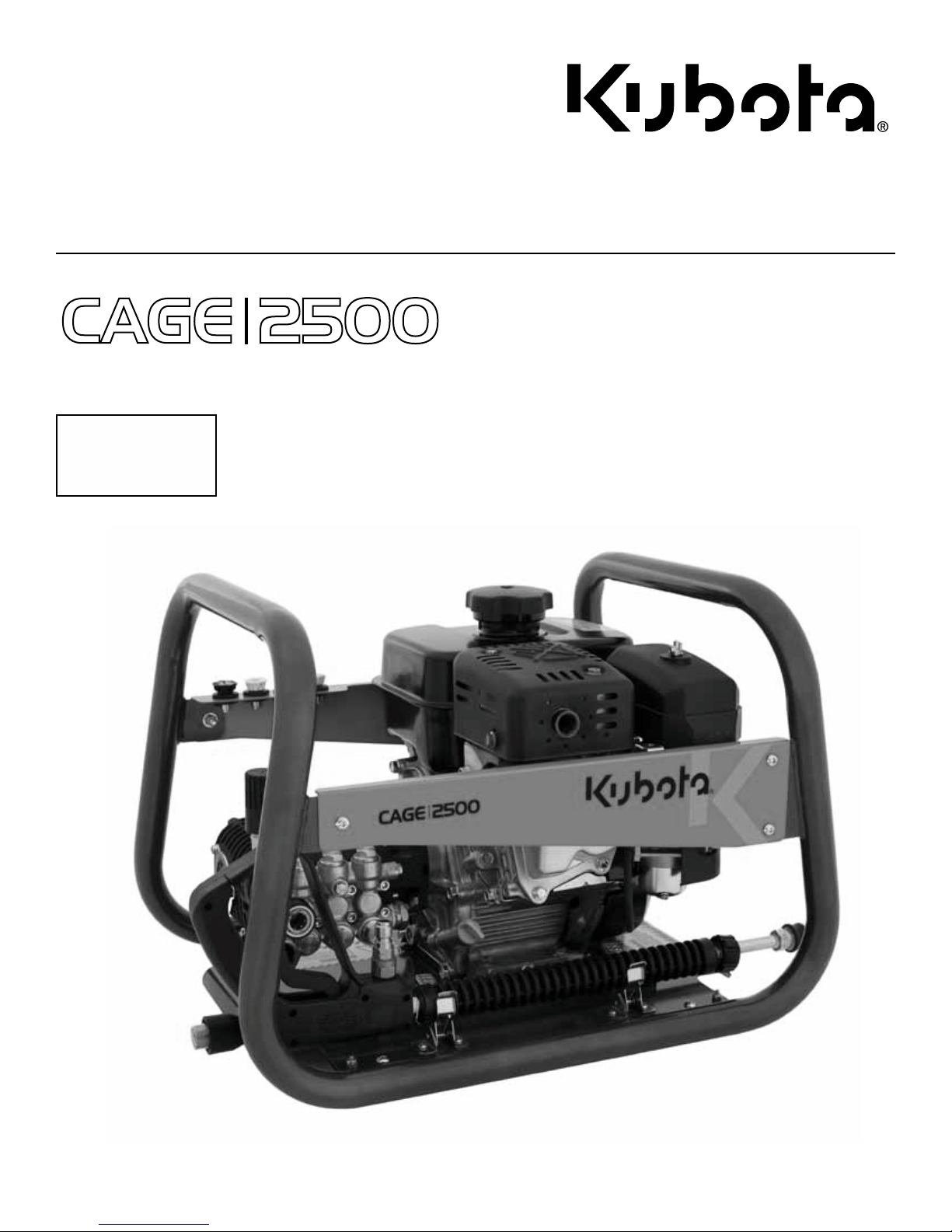
CAGE 2500
Extra Duty Series Pressure Washer
DRAFT
28/08/13 - 17h15
Product Code 77700-03518
2500 psi
2.7
Impact
Force
gpm
lb
Manual product number: 77700-04934
Effective September 2013
Page 2

Table of contents
Table of Contents
Introduction
Using the Operators Manual .................................................................... 3
Product Identification ............................................................................... 3
Product Serial number and Registration ................................................ 3
Safety
Description of Warning ............................................................................. 4
Description of Safety Symbols ................................................................ 4
Description of Hazard Warnings .............................................................. 4
Product labels/ Warning labels ............................................................... 5
Before you get started / Machine precautions ...................................... 6
Precautions Ventilation and Fire .............................................................. 7
Precautions High Pressure Stream / Slippery Surfaces ....................... 8
Precautions Protective Gear / Kick Back / Electrical Shock ................ 9
Precautions Hot Surfaces / Important Notices ................................... 10
Operating Instructions
Box Contents ........................................................................................... 11
Checklist ...................................................................................................12
Filling the Fuel Tanks ................................................................................12
Starting your Engine ................................................................................13
Cold Water Pressure Washing .................................................................14
Soap/Chemical injecter/ Stopping the machine ..................................15
Maintenence
Winterizing/ Motor & pump oil changes ...........................................16-17
Storage .....................................................................................................17
Periodic maintenance table ....................................................................18
Troubleshooting Charts
Engine ...................................................................................................... 19
Pump ..................................................................................................20-21
Pressure Regulator ............................................................................ 21-22
Soap injector ...........................................................................................23
Product specifications ...........................................................................24
Product Components
Parts and component diagrams with part numbers .................. 25 to 30
Limited Warranty Statement
Warranty Statement ................................................................................31
2
Page 3
Introduction
Congratulations on the purchase of your new Kubota Extreme Duty Series cold water pressure washer.
This product has been carefully designed and manufactured to provide the highest level of quality, safety,
endurance and optimal performance. Each component has been thoroughly and diligently tested to ensure
precise peak performance.
READING this operator manual completely and thoroughly will help to avoid personal injury and/or damage
to your machine. This manual describes simple safety procedure requirements, installation, operating functions, maintenance and troubleshooting steps.
All operators, should read this operator’s manual before attempting to operate the machine. Please read
and pay attention to all safety recommendations contained in this manual and those labeled on the machine.
The contents in this manual are based on the latest product information available at the time of publication.
Kubota reserves the right to make changes to price, color, materials equipment, specifications or models at
any time without notice.
Product identification
Recording the product information.
Once you have uncrated your new pressure washer write down the product model and serial number in the
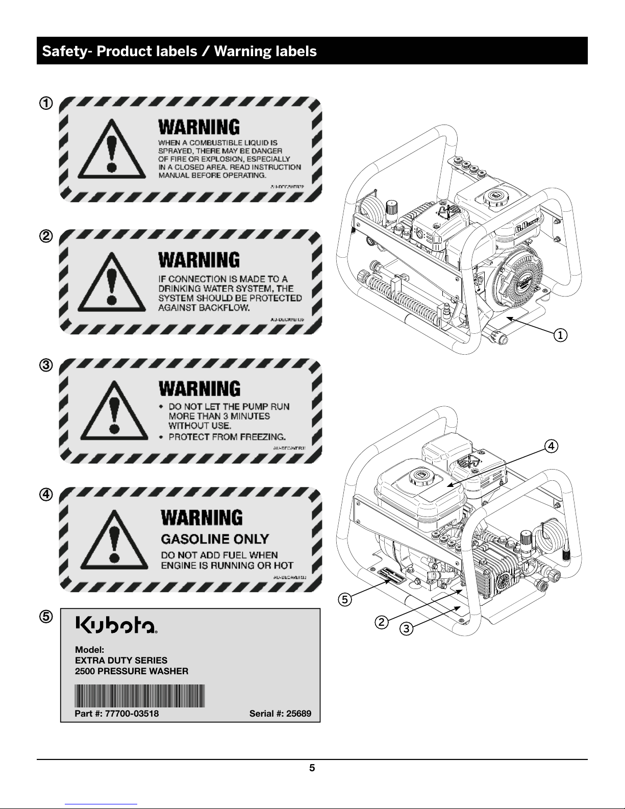
box below. This information is found on the product decal located on the motor mount plate. Refer to page 6
for decal location.
Add the complete dealer contact information and keep your operators manual for future reference.
If you need to contact an authorized servicing dealer refer to the customer
service line listed below for product or servicing information.
855-472-7282
Always provide product model, serial number and dealer information.
Product code : 77700-03518
Serial number :
Date of purchase :
Dealer name :
Dealer phone number :
3
Page 4
Safety -Description of warnings
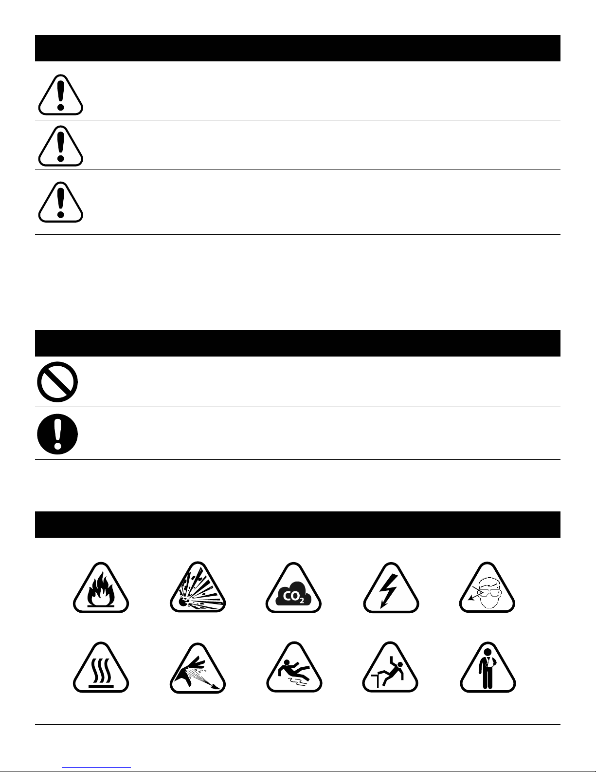
The «DANGER» symbol is used to outline a situation where danger is
DANGER
WARNING
CAUTION
Carefully read and follow the instructions or recommendations provided in each paragraph segment under
the headings of «DANGER» « WARNING» and « CAUTION». In each case the paragraphs provide important
information that should be to read.
It is recommended that after reading this information sheet , that a copy be kept as a future reference or for
other operators to read.
imminent and must be strictly avoided. Failure to comply could result in
serious damage to equipment personal injury or even death.
The« Warning» symbol describes the potential for danger or improper
set up and that should be avoided. Failure to comply could result in
serious damage to equipment, personal injury or even death.
The «Caution» symbol indicates the potential for a dangerous situation that can be avoided. Failure to take notice could result in potential
equipment damage and/ or minor to moderate personal injury. This
symbol can also outline.
Safety- Description of safety symbols
The « Prohibited » symbol signifies something « that should not be
PROHIBITED
done ». As a general indication the following symbol will be used in this
operator’s manual sheet to outline a prohibited action or procedure.
The « Mandatory » symbol signifies something « that must be done ».
MANDATORY
As a general indication the following symbol will be used in this operator’s manual to outline a mandatory action or procedure.
IMPORTANT
Indicates that machine or property damage could result if instructions
are not followed
Safety -Description of Hazard Warnings
FIRE
EXPLOSION
TOXIC FUMES
ELECTRIC SHOCK
FLYING OBJECTS
HOT SURFACE
HIGH PRESSURE
SLIPPERY
4
FALL
KICK BACK
Page 5
5
Safety- Product labels / Warning labels
1
2
3
5
4
Part #: 77700-03518 Serial #: 25689
Model:
EXTRA DUTY SERIES
2500 PRESSURE WASHER
1
2
5
4
3
Page 6
Safety - Before you get started/ Machine Precautions
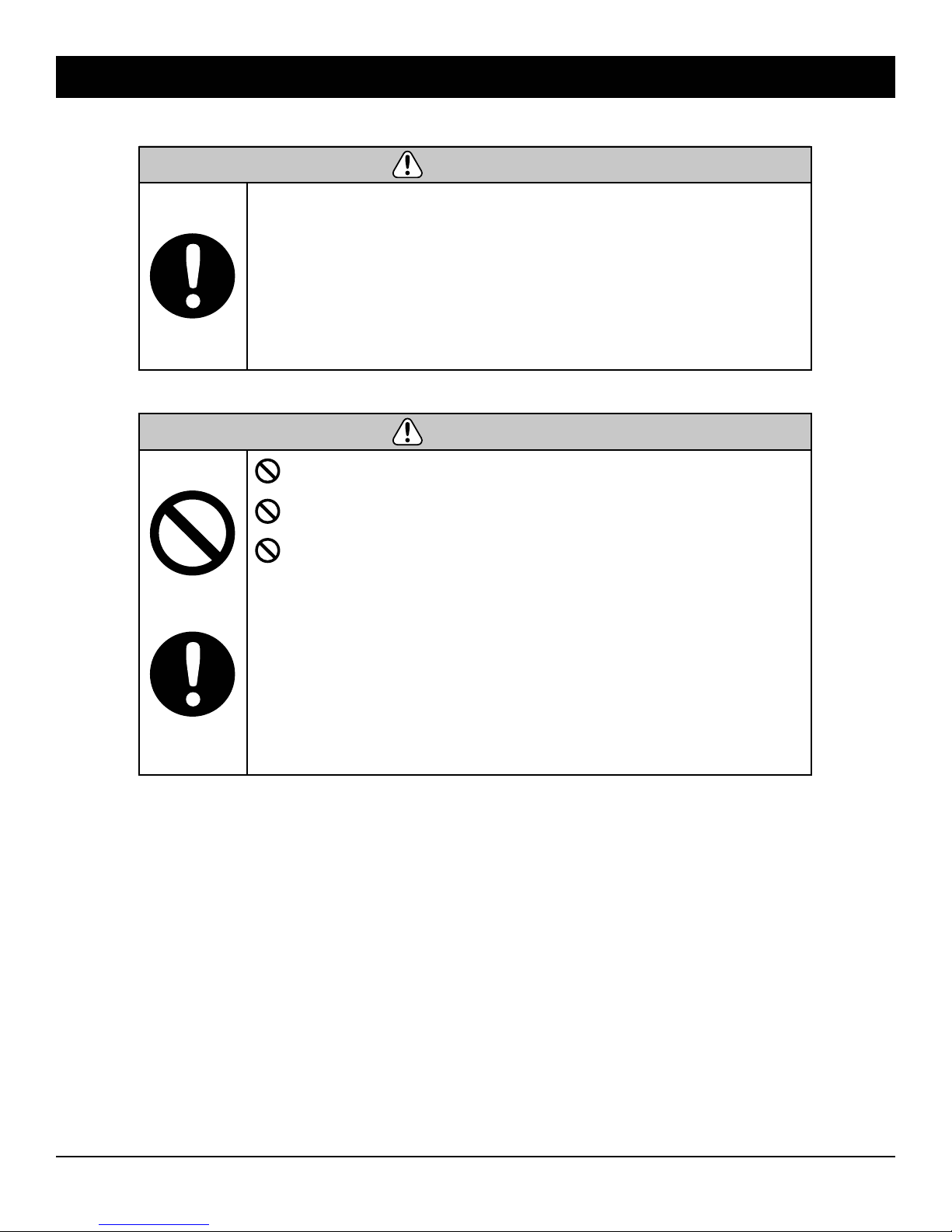
WARNING
• Read and understand both the engine’s and the pressure
washer manuals before using it. Know how to operate all controls
and how to stop the unit. Lack of knowledge can lead to accidents.
• Use with CAUTION high pressure spray can cause serious
bodily injury.
• Always wear long-sleeve shirt, pants, closed-toed shoes and
appropriate personal protective equipment (gloves, goggles,
apron) when handling chemicals.
WARNING
DO NOT Run the pressure washer without the water source being
connected and flowing into the pump.
DO NOT leave the unit running longer than 3 minute without using
the spray gun – the pump will overheat.
DO NOT let the unit freeze
• Always check the level of the engine oil prior to starting the
washer.
• Do not modify or alter this product or any of its components
without first consulting.
• Check parts for excessive wear regularly. Replace worn parts
with genuine parts.
• Always make sure all components are properly installed and
securely fastened before operation.
• Always follow chemical manufacturer’s instructions before
injecting soap or chemical products.
6
Page 7
Safety – Precautions Ventilation and Fire
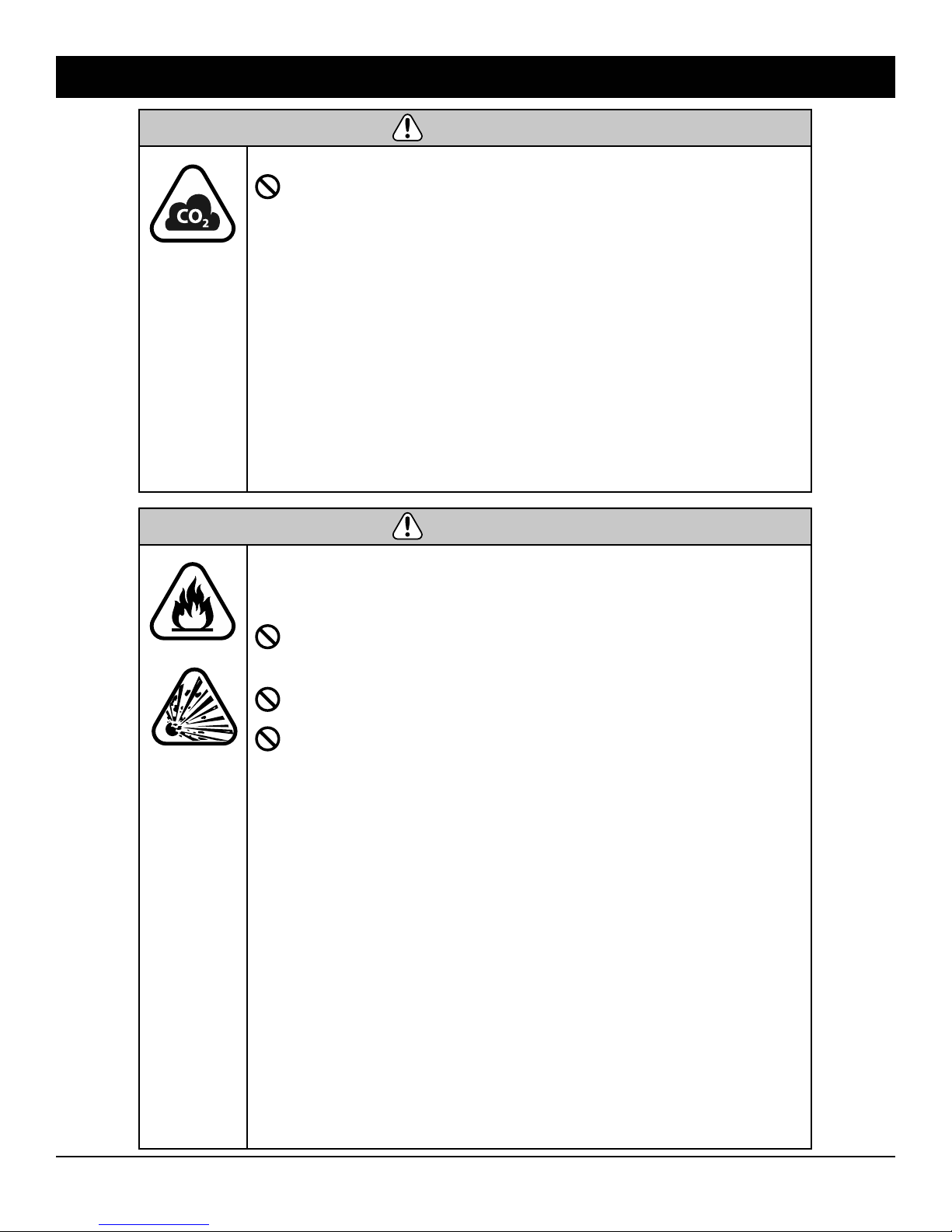
WARNING
This product is designed to be used outdoors.
NEVER operate this unit in an enclosed area even if the windows
are open.
• Running engine gives off carbon monoxide, an odorless,
colorless, poison gas. Breathing carbon monoxide can cause
headache, fatigue, dizziness, vomiting, confusion, seizure ,nausea,
fainting or death.
• Certain chemicals or detergents may be harmful if inhaled or
ingested, causing severe nausea, fainting, or poisoning.
• Ensure exhaust gas from entering a confined area through
windows, doors, ventilation intakes, or other openings.
• Use a respirator or mask whenever there is a chance that vapor
may be inhaled.
• When using a mask- READ manufacturer instructions to ensure the
mask can provide optimal protection.
WARNING
Fuel and fuel vapors are extremely flammable and explosive.
Fire or explosion can cause severe burns or death.
Before Adding or Draining Fuel
NEVER fill the engine fuel tank while the unit is running. Turn
pressure washer OFF and let cool for a more than 2 minute before
removing fuel cap. Loosen cap slowly to relieve pressure in tank.
NEVER operate near sparks, open flames, pilot lights, heat, and
other ignition sources.
DO NOT light a cigarette or smoke.
• Fill or drain fuel tank outdoors.
• DO NOT overfill tank. Refuel slowly to avoid spilling fuel. Allow
space for fuel expansion.
• DO NOT operate if fuel spills, wait until it evaporates before
starting engine.
Before Starting Equipment
• Ensure spark plug, muffler, fuel cap, and air cleaner are in place.
• DO NOT crank engine with spark plug removed.
Operating Equipment
• DO NOT tip engine or equipment at angle that causes fuel to spill.
• DO NOT spray flammable liquids.
Transporting or Repairing Equipment
• Transport/repair with fuel tank EMPTY or with fuel shutoff valve OFF.
• Disconnect spark plug wire.
Storing Fuel or Equipment with Fuel in Tank
• DO NOT store unit near furnaces, stoves, water heaters, clothes
dryers, or other appliances that have pilot light or other ignition
source which can create a sparks that can ignite fuel vapors.
7
Page 8
Safety – Precautions High Pressure Stream/ Slippery Surfaces
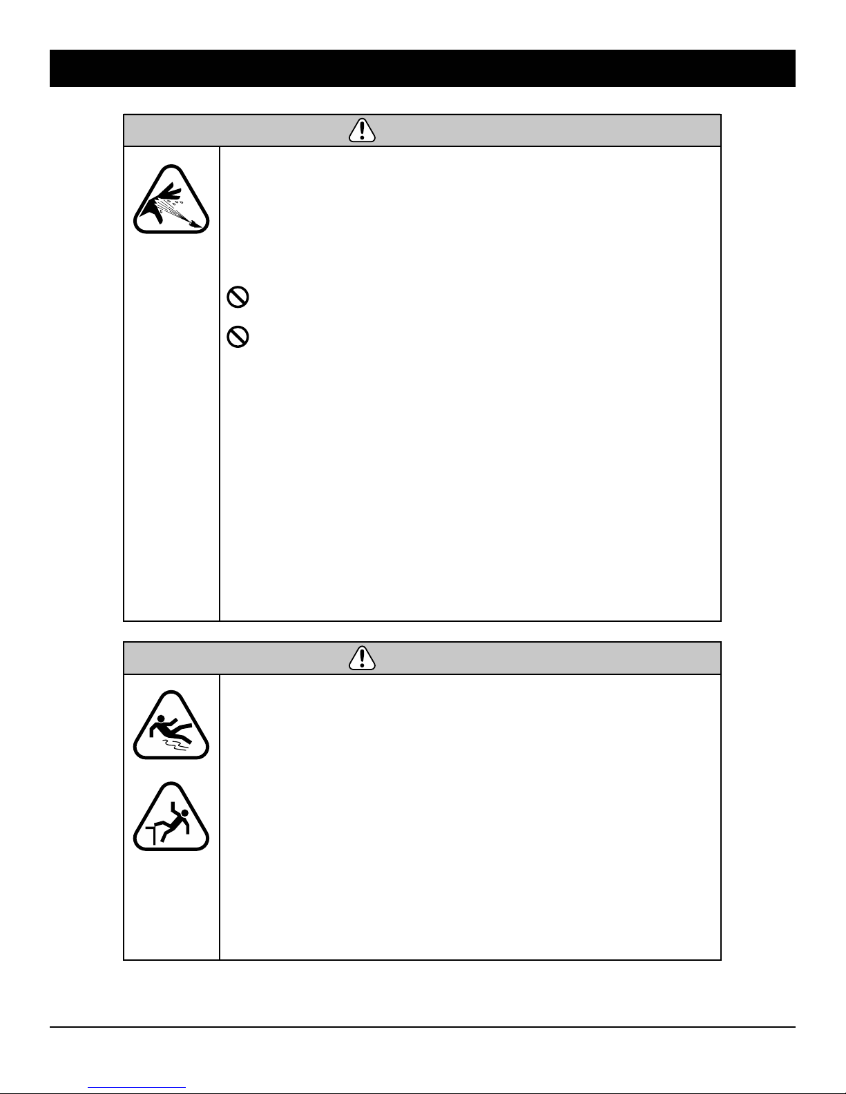
WARNING
High velocity spray fluids can penetrate skin, causing serious
injury. In the event that an accident occurs and spray appears to have penetrated the skin SEEK EMERGENCY MEDICAL ATTENTION . DO NOT treat water penetration into the
skin as a simple cut. If cleaning and/or soaping agents are
being used, advise the physician of the exact type.
DO NOT allow CHILDREN or adolcescents to operate pressure
washer.
NEVER aim spray gun at people, animals, or plants. 7
• ALWAYS point spray gun in safe direction and squeeze spray gun
trigger, to release high pressure, every time you stop engine.
• NEVER repair high pressure hose. Replace it.
• NEVER repair leaking connections with sealant of any kind.
Replace worn o-ring or seal.
• NEVER connect high pressure hose to nozzle extension.
• Keep high pressure hose connected to pump and spray gun
while system is pressurized.
• DO NOT secure spray gun in open position.
• DO NOT leave spray gun unattended while machine is running.
• NEVER use a spray gun which does not have a trigger lock or
trigger guard in place and in working order.
• ALWAYS be certain spray gun, nozzles and accessories are
correctly attached.
WARNING
Using a pressure washer can create puddles and slippery surfaces.
Kickback from spray gun can cause you to fall.
• The thrust from water travelling through the hose and nozzle can be
powerful enough to cause the operator to loose balance or footing.
• Avoid injury from potential kickback use both hands to firmly grasp
spray gun/ wand when using high pressure .
• Operate pressure washer from a stable surface.
• NEVER trigger the spray gun while on a ladder or roof
• DO NOT overreach or stand on an unstable surface.
• Ensure there is an adequate slope in the cleaning area to drain
excess water and reduce the possibility of a fall due to slippery
surfaces.
8
Page 9
Safety – Precautions Protective Gear / Kick Back / Electrical Shock
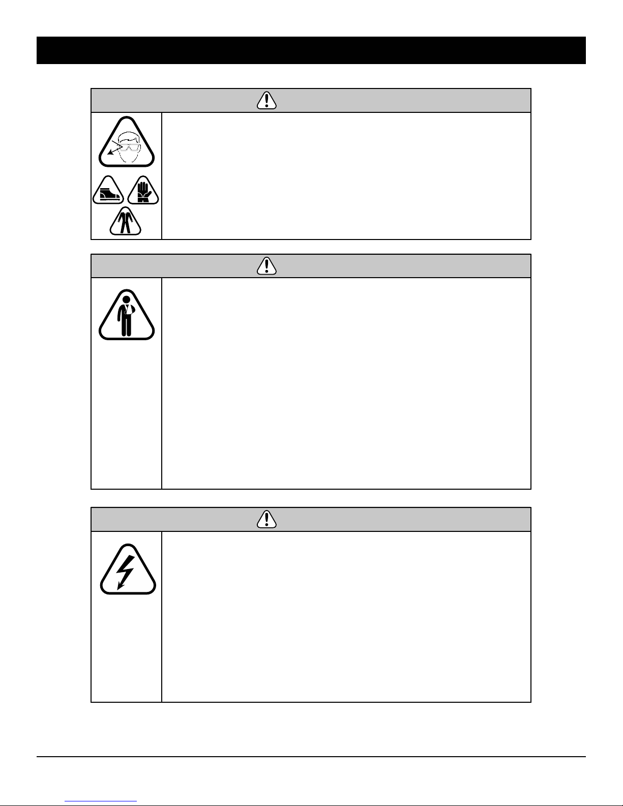
WARNING
Risk of eye injury.
High pressure spray can propel loose stones or objects at
high velocity.
• Always wear safety goggles and protective clothing when using
this equipment or in vicinity of where equipment is in use.
• Before starting the pressure washer, be sure you are wearing
adequate safety apparel, goggles, boots, gloves and work clothing .
• DO NOT substitute safety goggles for safety glasses.
WARNING
Starter cord kickback (rapid retraction) can result in bodily
injury.
Kickback will pull hand and arm toward engine faster than you
can let go. Broken bones, fractures, bruises, or sprains could
result.
• NEVER pull starter cord without first relieving spray gun pressure.
• When starting engine, pull cord slowly until resistance is felt and then
pull rapidly to avoid kickback.
• Always point the gun in a safe direction after each starting attempt,
where engine fails to run and squeeze spray gun trigger to release
high pressure.
• Firmly grasp spray gun with both hands when using high pressure
spray to avoid injury when spray gun kicks back.
Unintentional sparking can result in fire or electric shock.
• NEVER direct the jet toward the machine or toward any electrical
power source ( fuse box, transformer, electrical outlet) or appliance.
• NEVER use in the rain or during a thunderstorm.
When Adjusting or Making Repairs to Your Pressure Washer
• Disconnect the spark plug wire from the spark plug and place the
wire where it cannot contact spark plug.
Testing for Engine Spark
• Use approved spark plug tester.
• DO NOT check for spark with spark plug removed
WARNING
9
Page 10
Safety – Precautions Hot Surfaces / Important Notices
WARNING
Contact with muffler or motor components can result in serious
burns.
Exhaust heat/gases can ignite combustibles, structures or
damage fuel tank causing a fire.
• DO NOT touch hot parts and AVOID hot exhaust gases.
• Allow equipment to cool before touching.
• Keep at least 5 feet (1.5 m) of clearance on all sides of pressure
washer- including above the unit.
IMPORTANT
• If you have questions about intended use, ask dealer or contact the nearest
authorized servicing dealer.
• STAY ALERT when using a pressure washer.
• DO NOT operate when fatigued or under the influence of alcohol or drugs or
medications that make restrictions about operating equipment.
• FAILURE to follow warnings below can cause hazardous operating
conditions and will void all product warranties.
• DO NOT by-pass any safety device on this machine.
• DO NOT tamper with governed speed.
• DO NOT operate pressure washer above rated pressure.
• DO NOT modify alter or modify the equipment.
• NEVER operate units with broken or missing parts, or without protective housing
or protective covers.
• Before starting pressure washer in cold weather, check all parts of the equipment
to be sure ice has not formed there.
• NEVER move machine by pulling on hoses. Use the unit Cage frame as the handles.
• Use frame to securely tie down the unit while transporting in all types of vehicles.
• Check fuel system for leaks or signs of deterioration, such as chafed or spongy
hose, loose or missing clamps, or damaged tank or cap. Correct all defects before
operating pressure washer.
10
Page 11
Operating instructions
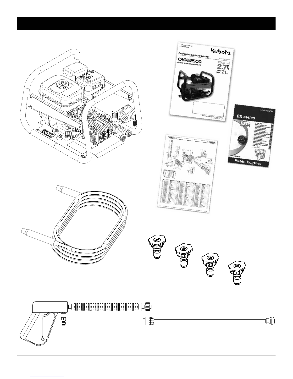
Box contents:
CAGE2500
Product manual
25' steel braided
3/8" hose
Pump parts manual
15º
Spray tip nozzles
Engine manual
25º
40º
Soap
Two piece 36" gun & wand
11
Page 12
Operating instructions
5
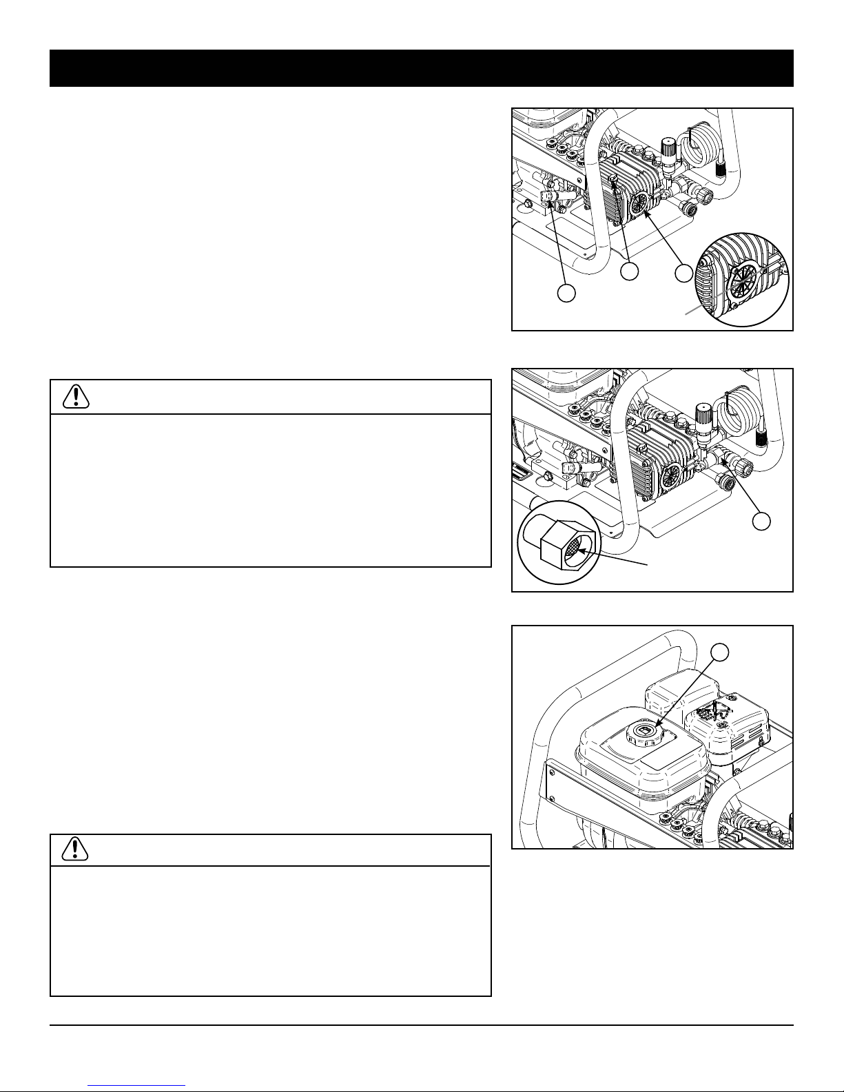
1. Make sure that all hoses are in good state, not cracked or
crushed.
2. Check the oil level of the pump. Pump must be in a level
position. Oil level must be halfway on the sight glass (A on
figure 1) or visible on the dipstick (B on figure 1).
3. Check the oil level of the engine. Engine must be in a level
position. Remove the oil filler cap/ dipstick (C on figure 1).
Oil level should be at bottom edge of the oil fill hole.
4. Check the presence and state of the water inlet gasket
(D on figure 2).
5. Check the water inlet mesh screen filter. Remove and
clean mesh filter.
WARNING: to avoid injuries :
• Before inspecting, cleaning, or repairing, make sure the
machine is on a level surface.
• Risk of injection; always put the safety-catch on the gun
as soon as the gun is not used, and especially for
replacement of nozzles.
• Always wear long clothes, gloves and safety glasses when
inspecting, cleaning, repairing and operating this machine.
B
C
A
Oil level
Figure 1
D
Mesh screen
Filling the fuel tanks
1. Remove the cap (E on figure 3) from the engine gas tank.
2. Fill with unleaded gasoline with a pump octane rating of
86 or higher. Do not overfill. Do not fill above the top of the
fuel filter screen. Avoid water or dirt entering while filling
the tank.
3. Screw back the gas tank cap.
• Do not remove fuel caps nor add fuel when the engine is
running or hot.
WARNING:
• Refuel outdoors only and in a well-ventilated area with the
equipment stopped.
• If any fuel is spilled, clean it up completely and allow
vapors to dissipate before starting the engine.
• Do not refuel while smoking, near an open flame, sparks,
or other heat source.
Figure 2
E
Figure 3
12
Page 13
Operating instructions / Starting your engine
DO NOT START ENGINE WITHOUT SUPPLYING WATER
TO THE PUMP
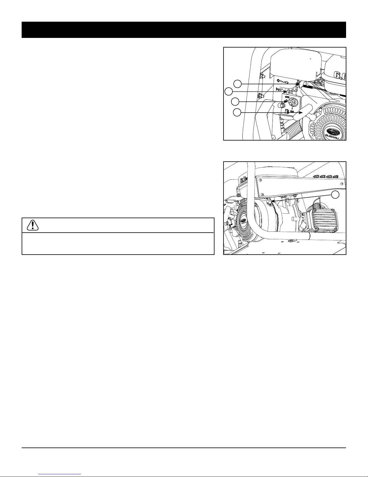
1. Turn down the fuel valve (F on figure 4) to open.
2. Close the choke by moving the lever (G on figure 4)
completely to the left.
3. Move the throttle lever (H on figure 4) from the right to
1/3 of the way to the left.
4. Turn the engine switch (I on figure 5) to ON position.
5. Pull the start grip (J on figure 4) lightly until resistance
is felt, and then pull briskly. Do not allow the starter grip
to snap back against the engine. Return it gently to
prevent damage to the starter.
6. As engine warms, gradually open the choke by moving
the lever (G on figure 4) to the right.
7. Let the engine idle for a couple of seconds.
8. Move the throttle lever (H on figure 4) completely to the
left, to full throttle.
H
G
F
J
Figure 4
I
DANGER:
• Never run the engine indoors or in a poorly ventilated area
such as tunnel or cave.
Figure 5
13
Page 14
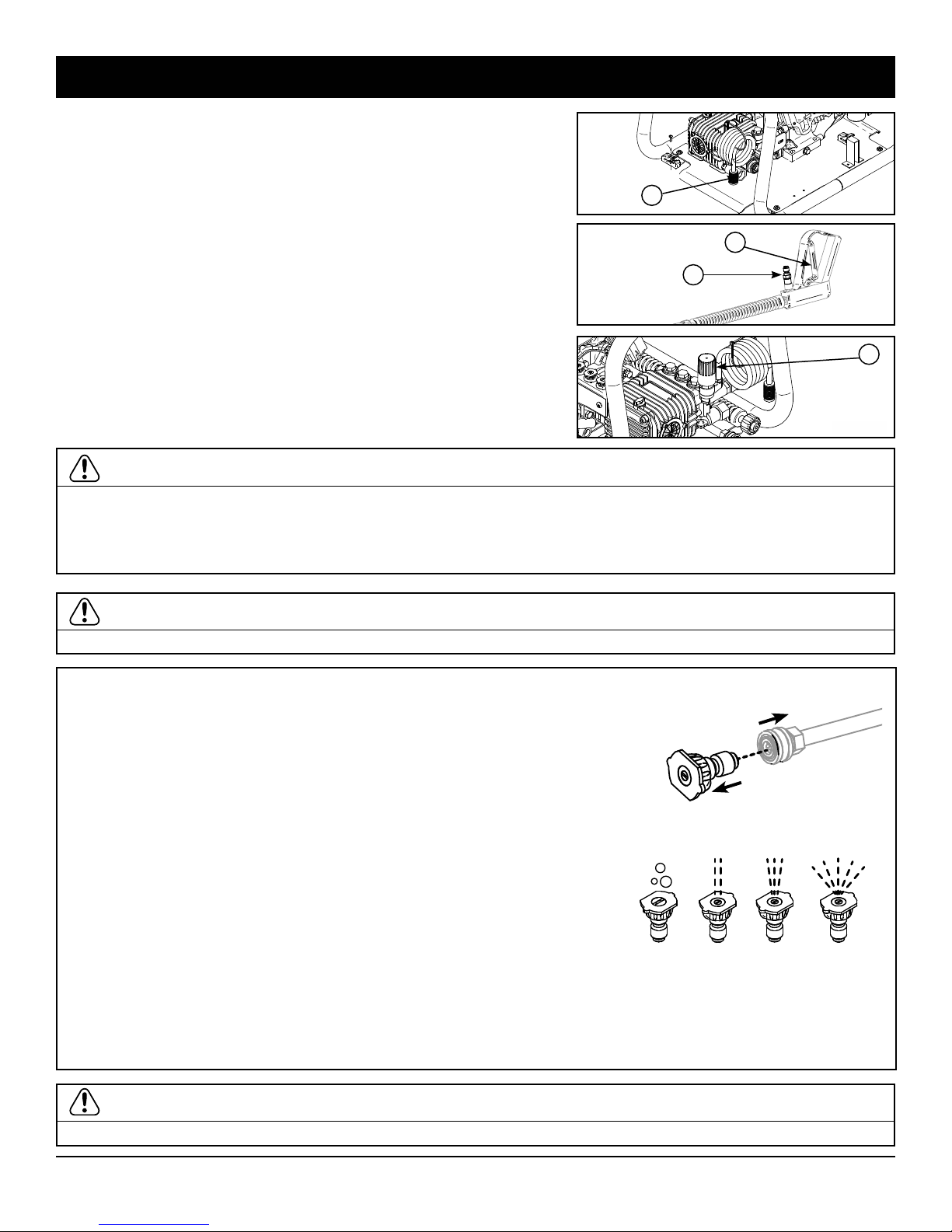
Operating instructions / Cold water pressure washing
L
M
1
2
3
4
1. Fill the fuel tanks (see “Filling the fuel tanks” previous section).
2. Connect a water supply hose at the machine inlet (K on figure 7)
and on the spray gun (M on figure 8). The supply hose flow rate
must be at least 4 gpm (15 l/min).
3. Depress the gun trigger (L on figure 8) until water flows out limpid
and regularly. Release the gun trigger.
4. Install a high pressure nozzle (refer to information box below) at the
wand outlet.
5. Start the engine according to “Starting the engine” previous section
and set the speed to full throttle.
6. Press the gun trigger and wash. Operate the gun continuously. Do
not press and release the trigger in cycles of less than 5 seconds.
7. Pressure can be adjusted by means of the high pressure regulator
(N on figure 9) up to2500 psi.
8. To stop, see section “Stopping procedure” further in this manual.
IMPORTANT:
Thermal Protector Feature on the pump.
When the gun has not been in use for 4 or 5 minutes the pressure in the pump builds and the internal water gets
hot. When the pump water temperature reaches 140°F the thermal protector will release a trickle of water onto the
ground to ensure that cooler fresh water circulates through the pump to protect it from heat damage.
K
Figure 7
L
M
Figure 8
Figure 9
N
WARNING:
• The muffler and other engine parts become very hot.Do not touch with bare hand.
Using and changing spray nozzle tips:
1. Installing or changing nozzles. Pull back on collar, insert new spray tip and
release collar. Tug on spray tip to ensure it is securely connected to the wand.
2. Pull back collar on quick–connect coupler and pull current spray tip off. Storing
nozzles in the designated holder will help to prevent debris from clogging the
tips.
3. Selecting the proper spray tip to tackle the job:
• YELLOW nozzle 15° Used to scour- chisel or peel away paint, grease, mud
or dirt. For surface preparation direct spray at a 45°angle to peel away
paint, and removing stubborn stains from concrete.
• GREEN 25° Spray is used for flushing dirt, mud and grime. Best suited to
wet sweep, leaves mud and dirt from walks, curbs, driveways, washing
swimming pool bottoms or degreasing an engine.
• WHITE nozzle 40° for gentle and thorough rinse before and after soaping
• BLACK nozzle used for detergent and soaping. The soaping function only
Soaper
Black
15º
Yellow
25º
Green
40º
White
works with the black soaping is in place.
Usage Tips
• For most effective cleaning, keep spray tip from 8 to 24 inches away from cleaning surface.
WARNING:
• If you spray too close when using a high pressure spray tip, you could damage the surface being cleaned.
14
Page 15
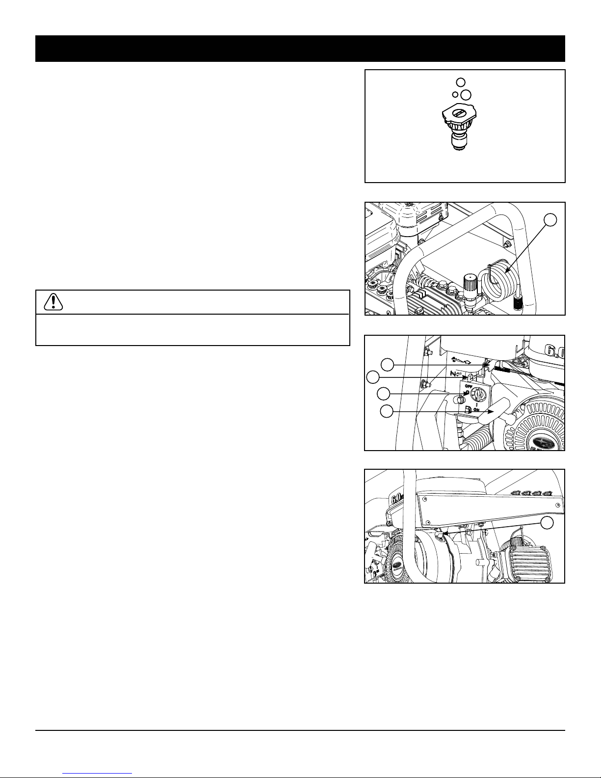
Operating instructions – Soap injection / Stopping the machine
Injecting soap
The pressure washer will only draw soap with the BLACK
SOAPING nozzle tip is attached.
WHITE, GREEN, AND YELLOW NOZZLE WILL NOT DRAW SOAP.
1. Remove the high pressure nozzle at the wand outlet and
replace it by the black soap nozzle (figure 11).
2. Insert the soap filter and hose (O on figure 12) in a liquid
soap container.
3. Depress the gun trigger. Water and soap mix will take
30 seconds to reach the nozzle and flow out.
4. Once soap application is finished, remove the soap
nozzle and install a high pressure nozzle to rinse (yellow,
green or white). Soap will flow out for 30 seconds and
then stop.
IMPORTANT:
• If corrosive products have been injected, rinse injector by
injecting water for a couple of minutes.
Soaper
Black
Figure 11
O
Figure 12
Stopping the Machine
1. If the machine has been used for soap injecting, install
a high pressure yellow, green or white nozzle at wand
outlet.
2. Depress the gun trigger until water flows out limpid and
regularly, and at a temperature of less than 100°F (40°C).
3. Release the gun trigger.
4. Move the throttle lever (H on figure 13) completely to
the right.
5. Let the engine idle for a couple of seconds.
6. Turn off the engine switch (I on figure 14).
7. Turn right the fuel valve (F on figure 13) to close.
8. Close the water supply valve.
9. Depress the gun trigger to release pressure from the
system.
10. Disconnect the water supply hose.
11. Make sure that all nozzles, tool, gun and wand are stored
in their proper place.
12. Make sure that all safety equipment is stored in its
proper place.
H
G
F
J
Figure 13
I
Figure 14
15
Page 16
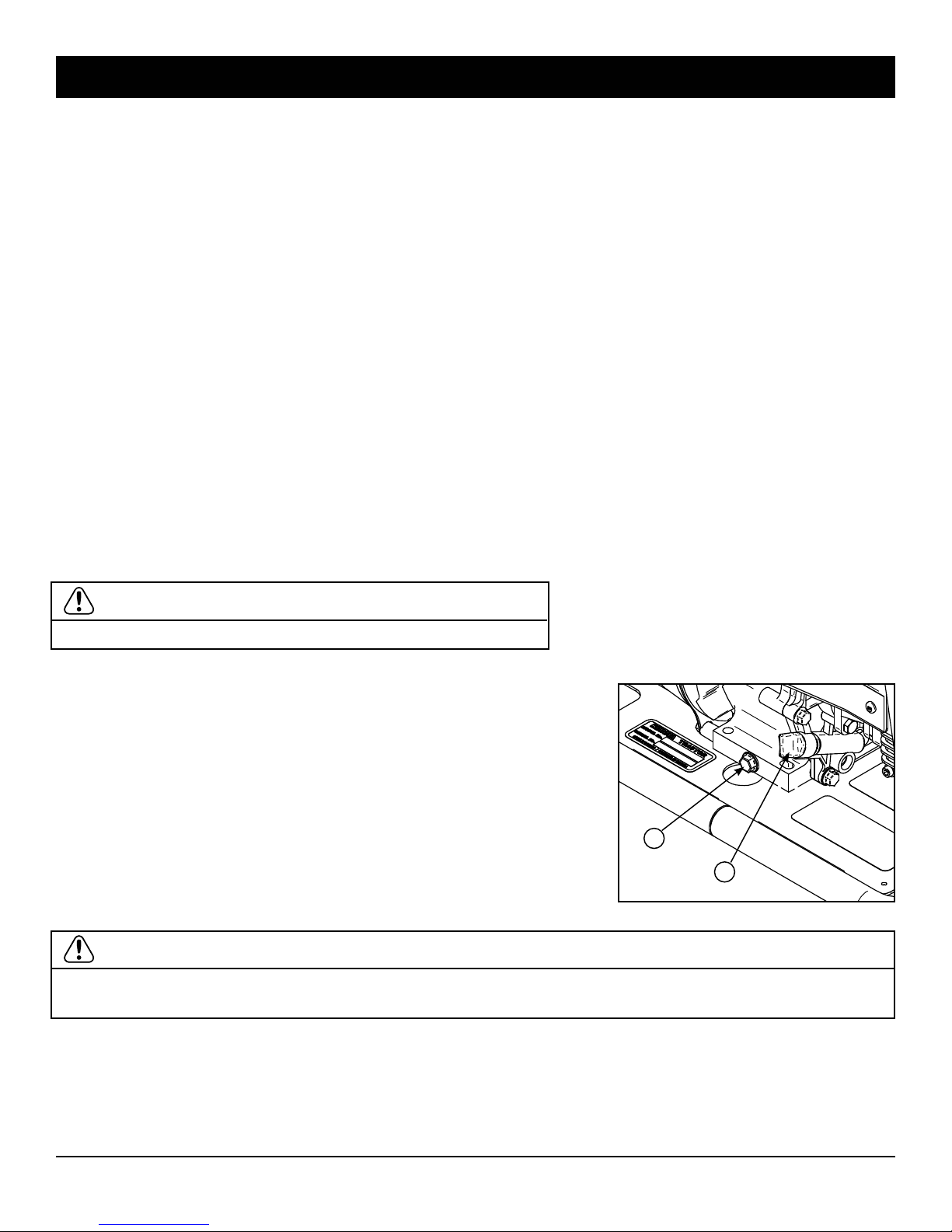
Maintenance – Winterizing / Motor oil change
E
Winterization
During winter and cold periods, if there is a freezing risk for the machine, it is recommended to take the following precautions immediately after stoppping the machine:
1. Disconnect the water supply hose from the machine inlet and replace it with a 5 feet (1.5 m) hose.
2. Place the free end of the hose into a container filled with a 50% antifreeze and 50% water solution. Use
automotive antifreeze. NEVER use plumbing antifreeze, alcohol or windshield washer fluid.
3. Remove the nozzle from the wand outlet.
4. Start the engine and let it idle.
5. Depress the gun trigger.
6. Depress the gun trigger again until antifreeze begins to flow out from the wand outlet, and then release
the trigger.
7. When the pump is primed and pumping antifreeze, release the gun trigger to fill the pressure washing
by-pass line with antifreeze.
8. Stop the engine.
9. Depress the gun trigger to release pressure from the system.
Antifreeze can be recovered at the next use and be used again on condition that you measure the concentration and add antifreeze to the solution if needed.
To recover antifreeze, connect a water supply hose to the machine inlet and open the supply hose valve. Do
not start the engine. The water supply pressure will be sufficient to slowly push solution to the outlet.
Dispose of used antifreeze according to environmental laws. Keep it in a closed container, then bring to the
nearest deposit. Do not throw to garbage or pour in the soil or in a sewer.
IMPORTANT:
• Do not forget that at 32°F (0°C), the machine can freeze.
Engine oil change
The first engine oil change must be done after 10 hours of use.
The next oil changes must be done after every 50 hours of use.
1. Place a container under the machine to recover used oil.
2. Unscrew the oil drain plug (A on figure 15).
3. Let oil flow slowly through the oil drain hole in the motor mount plate.
4. When engine crankcase is empty, screw back the drain plug.
5. Unscrew the oil filler cap/dipstick (B on figure 15).
6. Fill with SAE 10W-30 oil to bottom edge of the oil fill hole. Engine
A
B
crankcase capacity is 20.6 fluid ounces (0.6 l).
7. Screw the oil filler cap/dipstick back in place.
Figure 15
IMPORTANT:
Dispose of used oil according to environmental laws. Keep it in a closed container, and then bring to the
nearest deposit. Do not throw to garbage or pour in the soil or in a sewer.
16
Page 17
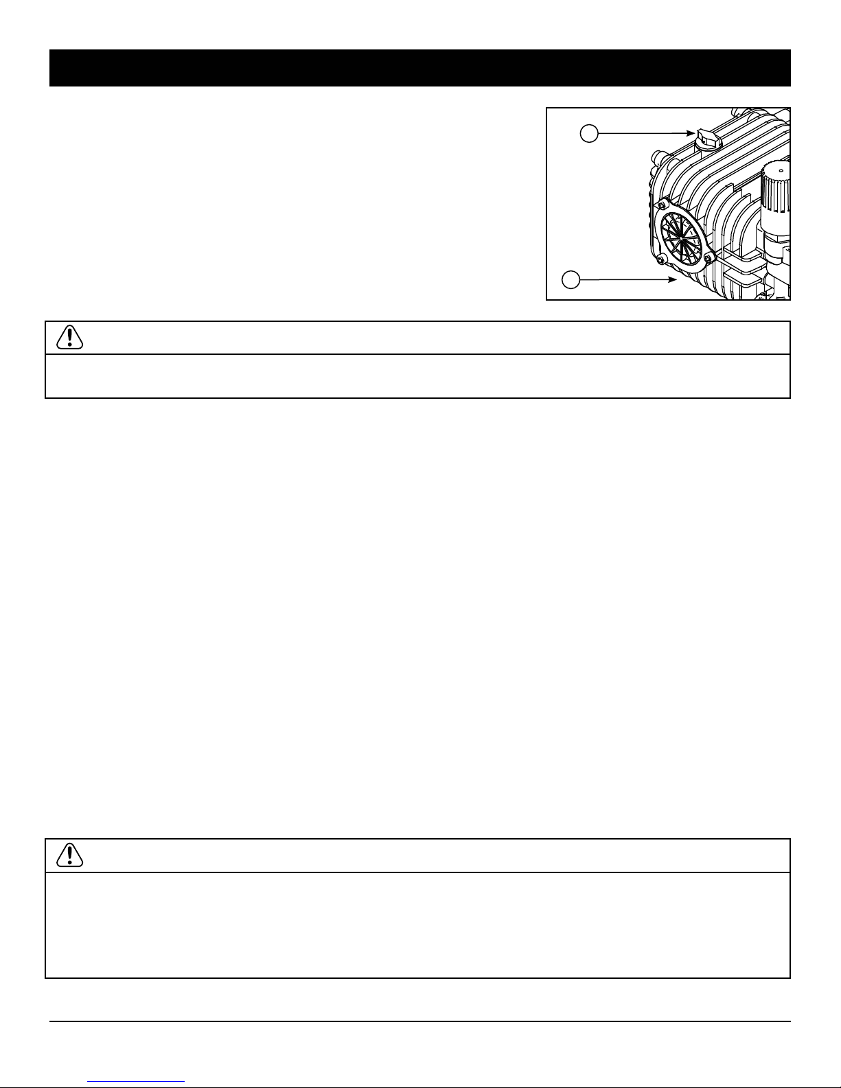
Maintenance – Storage / Pump oil change
2
Pump oil change
The first pump oil change must be done after 10 hours of use. The next
oil changes must be done after every 200 hours of use.
1. Place a container under the pump to recover used oil.
2. Unscrew brass oil drain plug (A on figure 16 under the pump).
3. Let oil flow slowly to avoid splash.
4. When pump crankcase is empty, screw back the drain plug.
5. Unscrew the oil filler cap/dipstick (B on figure 16).
6. Fill with NON DETERGENT SAE 30 oil to halfway on the sight glass.
Pump crankcase capacity is 14 fluid ounces (0.4 l).
7. Screw the oil filler cap/dipstick back in place.
IMPORTANT:
Dispose of used oil according to environmental laws. Keep it in a closed container, and then bring to the nearest deposit. Do not throw to garbage or pour in the soil or in a sewer.
Storage
If the machine is to be stored for a long time, take the following precautions:
1. Winterize the machine. Follow instructions specified at the end of previous section.
2. Using a siphon, empty the engine gas tank.
3. Recirculate antifreeze. Suck antifreeze from the container and return it into the same container. To
empty the carburetor, start the engine and let it run until engine stops by itself.
4. Using a siphon, empty the oil tank.
5. Change the engine oil. Follow instructions specified earlier in this section.
6. Change the pump oil. Follow instructions specified earlier in this section.
8. Store the machine in a cool dry place, sheltered against rain and well ventilated.
When the time comes to restart the machine, take the following precautions:
1. Make sure that all hoses are in good state, not cracked or crushed.
2. Check the state of the fuel oil filter. Replace the filter if it is damaged or dirty.
3. Check the presence and condition of the water inlet gasket.
4. Change the engine oil. Follow instructions specified earlier in this section.
5. Change the pump oil. Follow instructions specified earlier in this section.
6. Recover antifreeze from the machine. Follow instructions specified at the end of previous section.
7. Charge and connect the battery. Follow instructions specified earlier in this section.
8. Check the general condition of the machine. Perform a complete visual inspection.
9. When everything seems to be perfect, fill the tanks and start the machine.
B
A
Figure 16
WARNING:
• Refuel outdoors only and in a well-ventilated area with the equipment stopped.
• If any fuel is spilled, clean it up completely and allow vapors to dissipate before starting the engine.
• Do not refuel while smoking, near an open flame, sparks, or other heat source.
• Always wear long clothes, gloves and safety glasses when inspecting, cleaning, repairing and
operating this machine.
17
Page 18
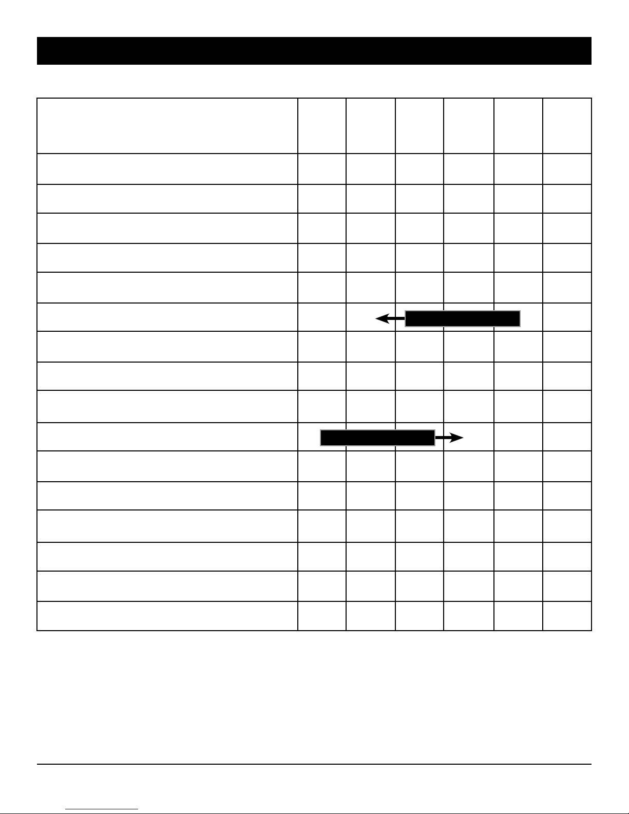
Periodic maintenance schedule table
Maintenance items Daily Every Every Every Every Every
50 100 200 500 1000
hours hours hours hours hours
Check general condition of the machine •
Check engine oil level •
Check pump oil level •
Check hoses condition •
Check water inlet gasket and filter •
Change engine oil •
Check bolts and nuts tightening •
Clean engine air cleaner •
Clean engine spark plug •
Change pump oil •
Replace engine air cleaner element •
Clean engine fuel cup (filter) •
Clean and adjust engine spark plug •
Replace engine spark plug •
Clean and adjust engine carburetor •
Initial 10 hours
Initial 10 hours
Replace fuel lines •
18
Page 19
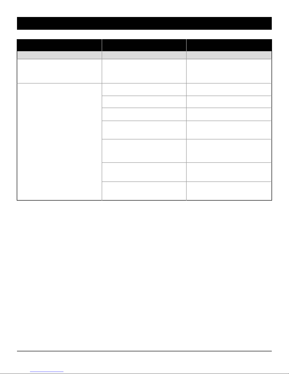
Trouble shooting guide
FAULT CAUSE REMEDY
ENGINE
The engine stops and does not
restart.
The engine does not start.
The oil level is too low. The
engine oil alert system cuts the
ignition.
No fuel in tank.
Fuel valve close.
Choke open.
Bad fuel; wrong fuel; contaminated fuel.
Spark plug wet with fuel (flooded engine).
Spark plug faulty, fouled or
improperly gapped.
Carburetor, ignition, valves, etc.
Add oil in the engine crankcase.
Adjust oil level.
Check fuel level.
Open fuel valve.
Close choke to start.
Drain fuel tank and carburetor.
Refuel with fresh gasoline.
Dry and reinstall spark plug.
Start engine with throttle lever
in maximum speed position.
Adjust or replace spark plug.
Take engine to an authorized
Subaru service center.
19
Page 20
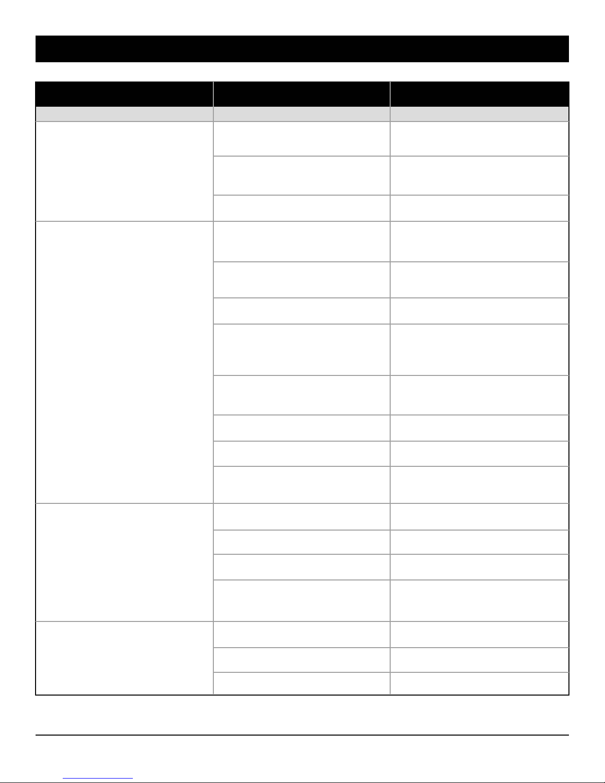
Trouble shooting guide
FAULT CAUSE REMEDY
PUMP
The motor runs but the pump
does not work.
The pump valves are jammed
by dirt.
Clean the valves. Check or add
a filter at the pump inlet.
The pump runs, but does not
give maximum pressure.
The O’ rings of the valves are
damaged.
The pump key is broken.
The nozzle is worn or has not
the proper size.
The soap nozzle is installed.
Leaks in the high pressure line.
The seat or the valve of the
washing regulator are dirty or
worn.
The pump valves are worn or
dirty.
Pump water seals are worn.
Pump is sucking air.
Replace.
Replace.
Check for the recommended
size or replace.
Replace with a high pressure
nozzle.
Stop the leaks.
Check, clean or replace the
defective parts.
Clean or replace.
Replace.
Check the supply piping.
Fluctuating pressure.
Excessive vibration in delivery
hose
and gun.
Water supply is insufficient.
Valves are worn or dirty.
Water seals are worn.
Pump is sucking air.
Water supply is insufficient.
Pump valves are dirty or worn.
Pump water seals are worn.
A connecting rod is broken.
20
Check if supply flow provides
the pump’s needs.
Clean or replace.
Replace.
Check the supply piping.
Check if supply flow provides
the pump’s needs.
Clean or replace.
Replace.
Replace.
Page 21
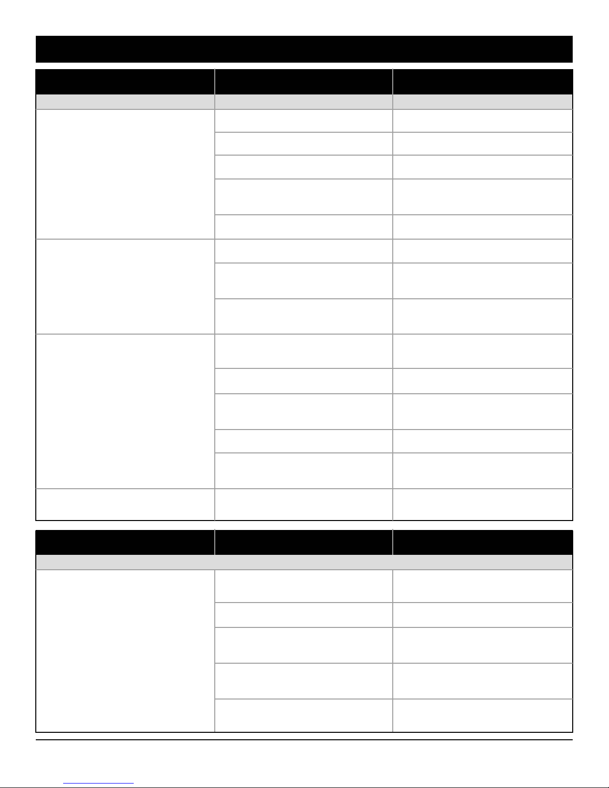
Trouble shooting guide
FAULT CAUSE REMEDY
PUMP
Noisy pump.
Bearings are worn.
Replace.
Presence of water in oil
(white oil).
Oil dripping under the pump.
Pump is sucking air.
Water supply is insufficient.
Inlet water temperature is too
high.
The pump key is worn.
Pump water seals are worn.
High humidity in the air.
Cleaning of the pump with the
nozzle.
Crankshaft oil seal broken or
worn.
Piston guide scratched or worn.
Piston guide oil seal broken or
worn.
Check the supply piping.
Check the supply flow.
Lower the inlet water temperature.
Replace.
Replace.
Increase the oil change
frequency.
Never direct the jet toward the
machine.
Replace.
Replace.
Replace.
Water dripping between pump
head and crankcase.
Air vent jammed.
Air vent replaced by a non-ventilated cap.
Pump water seals are worn.
Clean.
Put the origin parts back.
Replace.
FAULT CAUSE REMEDY
PRESSURE REGULATOR
The regulator engages and
releases when the gun trigger is
released.
The gun does not properly
close.
Leaks on the high pressure line.
The regulator check valve does
not properly close.
The regulator piston seal kit is
worn.
The regulator guide seal kit is
worn.
Adjust, repair or replace the
gun.
Stop the leaks.
Replace the defective parts.
Replace the defective parts.
Replace the defective parts.
21
Page 22
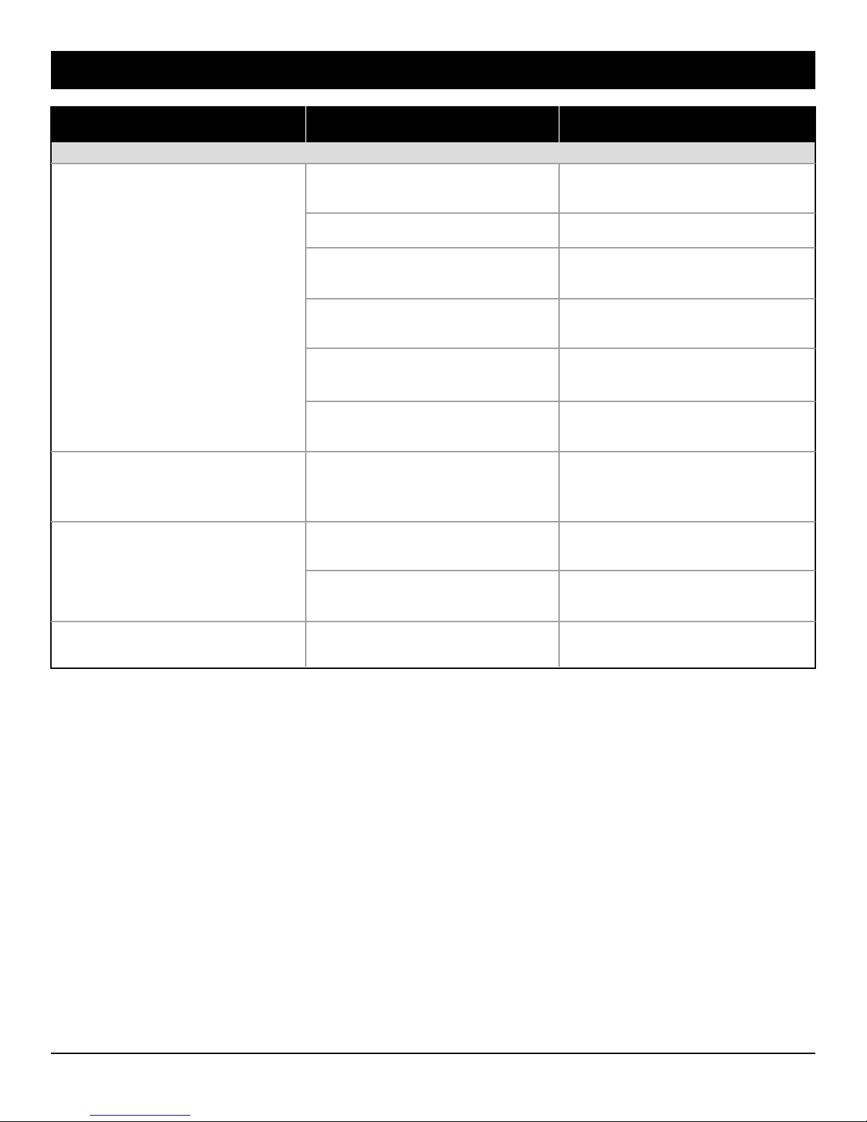
Trouble shooting guide
FAULT CAUSE REMEDY
PRESSURE REGULATOR
The regulator engages and
releases when the gun trigger is
released.
The regulator engages and
releases when the gun trigger is
engaged.
Pump staying under pressure
when the gun is released.
The gun does not properly
close.
Leaks on the high pressure line.
The regulator check valve does
not properly close.
The regulator piston seal kit is
worn.
The regulator guide seal kit is
worn.
Water coming into the soap jar.
There is not enough flow to
maintain the regulator engaged
(jammed nozzle).
The gun does not properly
close.
The regulator check valve does
not close.
Adjust, repair or replace the
gun.
Stop the leaks.
Replace the defective parts.
Replace the defective parts.
Replace the defective parts.
Clean or repair the soap injector check valve.
Clean the nozzle (problem
encountered with interchangeable nozzles).
Repair the gun.
Repair the check valve.
Water dripping from the regulator guide.
The regulator guide seal kit is
worn.
Replace the defective parts.
22
Page 23
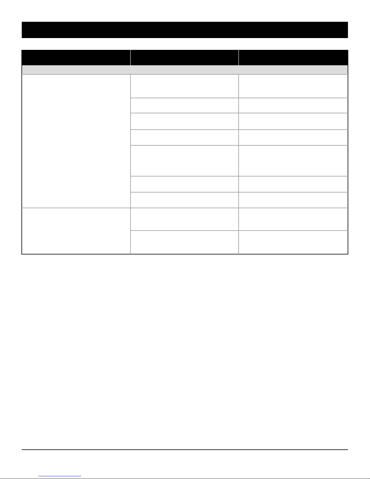
Trouble shooting guide
FAULT CAUSE REMEDY
SOAP INJECTOR
Soap does not inject.
Water goes into the soap jar
when in high pressure mode.
The soap hose or the soap filter
is dirty.
The soap nozzle is not installed.
The injector is dirty or jammed.
The injector restrictor is worn.
The pressure hose is damaged
or has a too small inside diameter.
The pressure hose is too long.
The gun does not open enough.
The soap nozzle is dirty or
damaged.
The injector check valve is dirty
or worn.
Check and clean.
Install the soap nozzle.
Check and clean.
Replace.
Replace with a new hose of the
right size.
Try with the original hose.
Adjust the gun piston.
Clean or replace.
Clean or replace.
23
Page 24
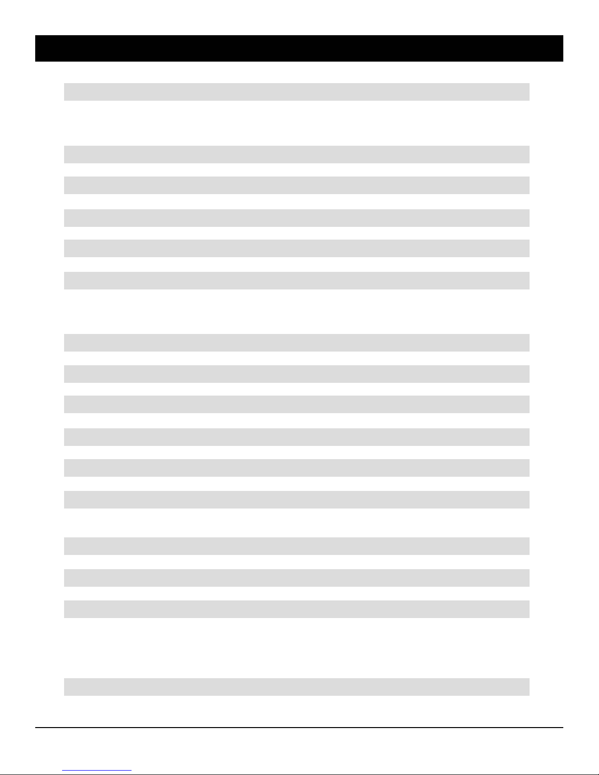
Product Specifications
Product code 77700-03518
Usage Extra Duty commercial
ENGINE
Manufacturer Subaru
Displacement 169cc
Max RPM 4 000
Fuel capacity (US gallons/ Liters) 0.95 / 3.6
Oil alert protection Ye s
Air cleaner Dual element
Muffler Low tone rigid design
Emission rating Tier III EPA / CARB
Oil Type 10W 30
Oil crankcase capacity (FL oz / Liters) 20.6 / 0.6
PUMP
Drive Type Direct crankshaft
Ceramic plungers 3
Crankcase Anodized Aluminium
Pump head Forged brass
PSI 2500
Gallons per minute /GPM 2,7
Impact force (lbs) 7,1
Thermal protector Ye s
Soap/chemical injector Ye s
Oil Type non detergent SAE 30
Oil crankcase capacity (FL oz / Liters) 9.5 / 0.28
ACCESSORIES
Hose type rubber
Hose diameter (inches) 3/8"
Hose rating (psi) up to 3000
Hose length (feet) 25
Gun/wand 2 piece 36" gun & wand
Spray Nozzles (4) 15°- 25°-40° -Soap
DIMENSIONS
Weight (lbs) 76
Size (L) (W) (H) 28 x 18 x 17
24
Page 25
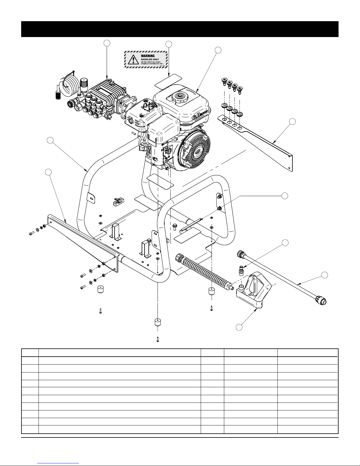
View CAGE assembly
2
1
5
10
3
4
6
9
7
8
REF. DESCRIPTION QTY PART # CODE
1 CAGE frame 1 77700-04931 N010-0005-G
2 Pump assembly 2.5 gpm, 2700 psi pump assembly 1 77700-04935 RE-BWDK2527GA
3 Engine, 5.7 hp subaru, recoil start, crankshaft 3/4" oil sensor 1 77700-04936 RO-EX170DM2231
4 Reinforcing plate (LEFT) 1 77700-04929 N010-0003-PZ02-O
5 Reinforcing plate (RIGHT) 1 77700-04930 N010-0003-PZ03-O
6 Sponge rubber 1/8" x 1' lg. 1 77700-04938 SN-892382
7 Single lance 36" insulated, 2 sections 1/4" m-m 1 77700-04907 BE-85205063
8 Spray gun 7 gpm, 2750 psi, cold water 1 77700-04906 AU-ST1100B
9 Quick coupler, 3/8" x 3/8" npt male, ptd 1 77700-04921 JB-3FPMI
10 Decal Warning «gazoline only» 1 77700-04902 AU-DECAVER33
25
Page 26
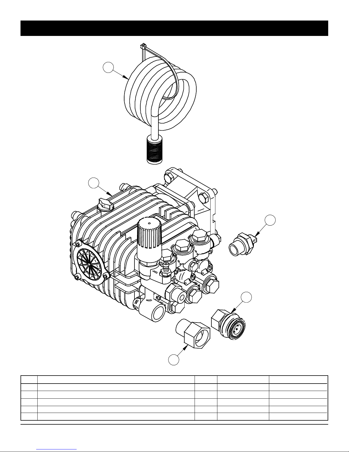
Pump exploded views - RE-BWDK2527GA
2
1
5
4
3
REF. DESCRIPTION QTY PART # CODE
1 Pump 2.7 gpm, 2700 psi, 3450 rpm, 3/4" h-sh. 1 77700-04917 CO-BWDK2527G
2 Soap hose and filter kit 1 77700-04928 MS-FBS
3 Adaptor, swivel 3/4" x 1/2" with filter 1 77700-04926 JB-SGM0004BR
4 Quick coupler, 3/8" x 3/8" npt female, brass/plastic 1 77700-04919 JB-3FBP
5 Thermal protector, 3/8", 140°F 1 77700-04927 JB-TP138
26
Page 27
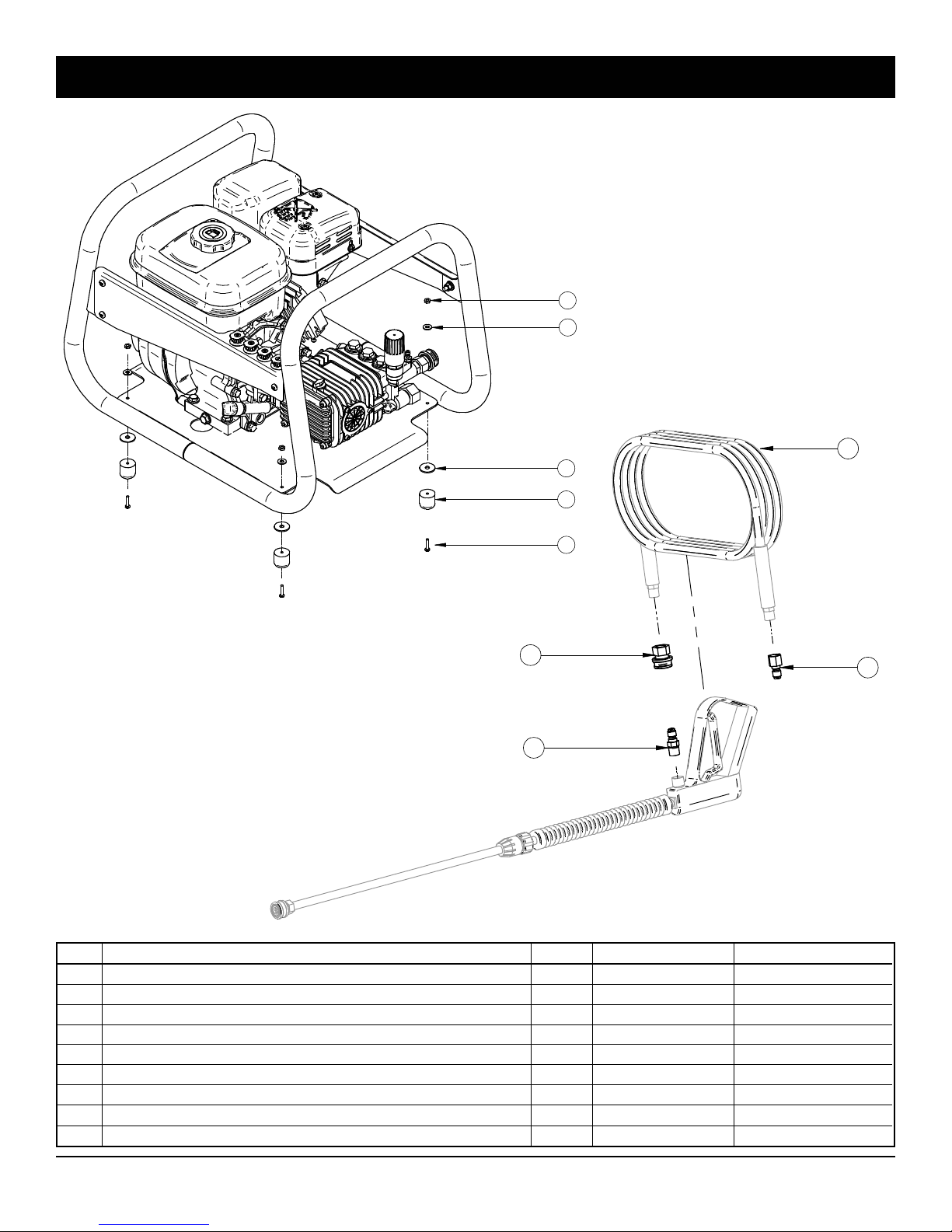
Exploded views - N010-0005-KIT1 (77700-04932)
5
4
3
2
9
1
6
8
REF. DESCRIPTION QTY PART # CODE
1 Bolt hex. 8-32 x 1" lg. gr. 5, ptd 4 77700-04909 BT-8321
2 Rubber bumper 1" od x 1" high, hole 5/32" 4 77700-04937 SN-315253
3 Flat washer 1/4" x 1" od. stainless 4 77700-04912 BT-FW141SS
4 Flat washer 1/2" (ø8 int), ptd 4 77700-04914 BT-FW8
5 Nut hex. nylon insert 8-32 nc, stainless steel 4 77700-04915 BT-LN832SS
6 Quick coupler, 3/8" x 3/8" npt female, brass/plastic 1 77700-04919 JB-3FBP
7 Quick coupler, 3/8" x 3/8" npt female, ptd 1 77700-04920 JB-3FPI
8 Quick coupler, 3/8" x 3/8" npt male, ptd 1 77700-04921 JB-3FPMI
9 Hose 3/8" x 25', 3000 psi, black 1 77700-04905 AU-H3825
7
27
Page 28
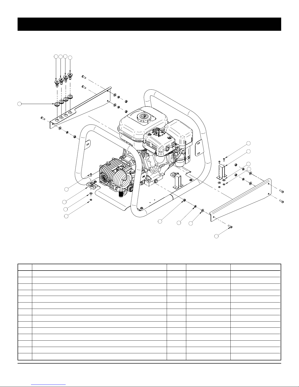
Exploded views - N010-0005-KIT2 (77700-04933)
2
4
3
1
5
10
13
11
12
10
9
11
12
8
14
7
6
REF. DESCRIPTION QTY PART # CODE
1 Flat spray qc nozzle 15° #3 stainless steel - yellow 1 77700-04922 JB-QMEG1503
2 Flat spray qc nozzle 25° #3 stainless steel - green 1 77700-04923 JB-QMEG2503
3 Flat spray qc nozzle 40° #3 stainless steel - white 1 77700-04924 JB-QMEG4003
4 Soap nozzle qc 65° #40, brass - black 1 77700-04925 JB-QMEG6540BR
5 Bushing 1/2" id, rubber 4 77700-04918 JA-77
6 Bolt 1/4" x 3/4", round head, ptd 6 77700-04908 BT-1434RSMS
7 Flat washer 5/8" (ø 1/4" int.), ptd 6 77700-04911 BT-FW14
8 Nut hex. 1/4" nc, ptd 6 75599-31011 BT-N14
9 Wand clip kit 1/2" 1 77700-04897 AC-12200
10 Bolt hex. 8-32 x 1/2" lg. gr. 5, ptd 6 77700-04910 BT-83212
11 Flat washer 1/2" (ø8 int), ptd 6 77700-04914 BT-FW8
12 Nut hex. 8-32 nc, ptd 6 77700-04916 BT-N832
13 Spring clip (2/p) 1 77700-04898 AU-131508
14 Lockwasher 1/4", ptd 6 75599-33011 BT-LW14
28
Page 29
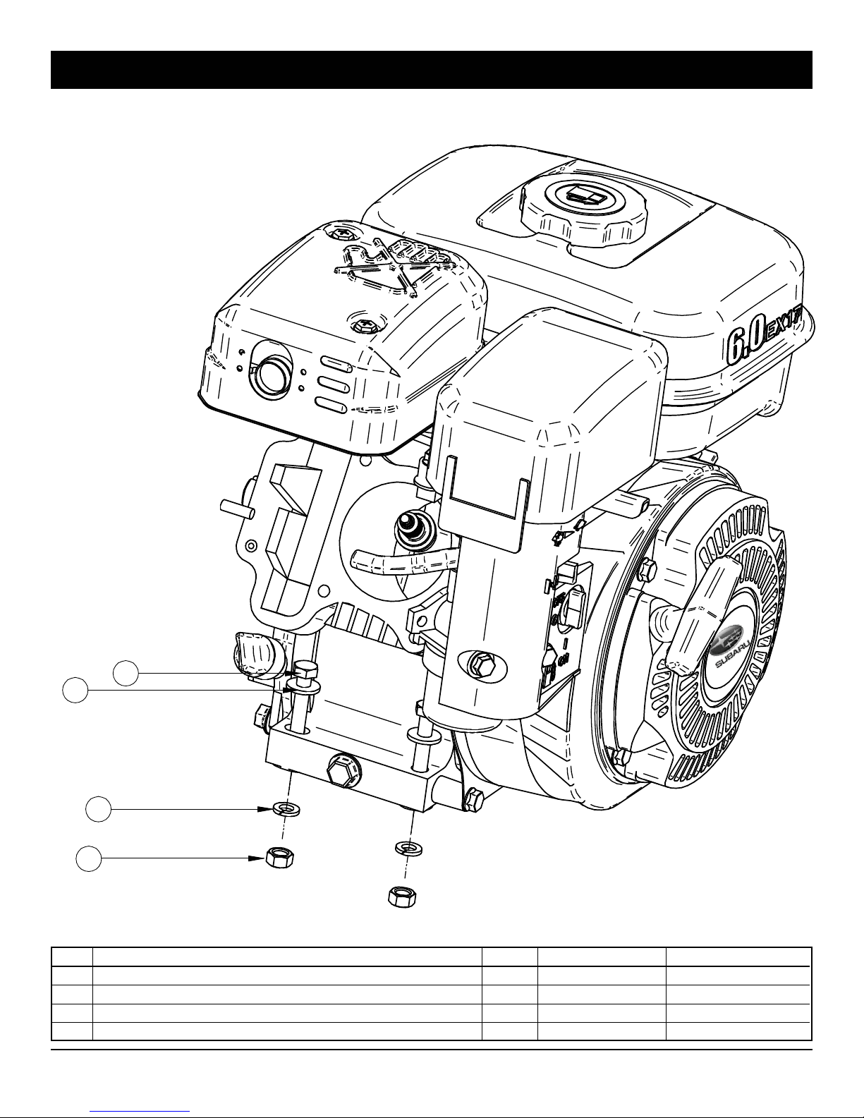
Subaru engine exploded views - RO-EX170DM2231
1
2
3
4
REF. DESCRIPTION QTY PART # CODE
1 Bolt hex. 5/16" x 1 1/2" nc gr. 5, ptd 4 75599-01230 BT-516112
2 Flat washer 11/16" (ø 5/16" int), ptd 4 77700-04913 BT-FW516
3 Lockwasher 5/16", ptd 4 75599-33012 BT-LW516
4 Nut hex. 5/16" nc, ptd 4 75599-31012 BT-N516
29
Page 30
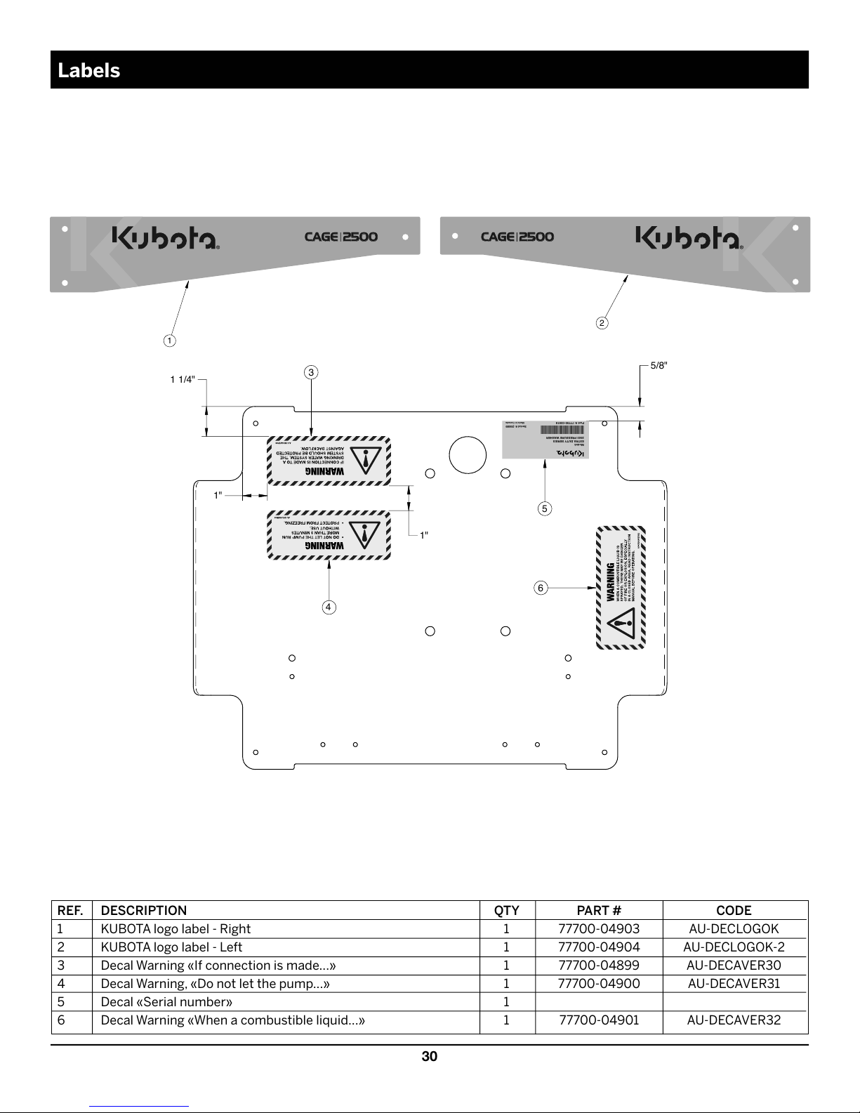
30
3
6
4
5
1 1/4"
1"
1"
5/8"
1
2
Part #: 77700-03518
Serial #: 25689
Made in Canada
Model:
EXTRA DUTY SERIES
2500 PRESSURE WASHER
CAGE 2500
CAGE 2500
REF. DESCRIPTION QTY PART # CODE
1 KUBOTA logo label - Right 1 77700-04903 AU-DECLOGOK
2 KUBOTA logo label - Left 1 77700-04904 AU-DECLOGOK-2
3 Decal Warning «If connection is made...» 1 77700-04899 AU-DECAVER30
4 Decal Warning, «Do not let the pump...» 1 77700-04900 AU-DECAVER31
5 Decal «Serial number» 1
6 Decal Warning «When a combustible liquid...» 1 77700-04901 AU-DECAVER32
Labels
Page 31

Product warranty
Pressure washers manufactured by the KUBOTA TRACTOR COMPANY are warranted, to the original purchaser, to be free from
defects in materials and workmanship for the periods specified below. Normal use conditions, according to the instructions in this
manual, apply. This limited warranty is subject to the exclusions listed below, is calculated from the date of delivery to the original
purchaser, and applies to the original components only. Parts replaced under this warranty will assume the remainder of the corresponding part’s warranty period.
5 YEAR PARTS, 1 YEAR LABOUR WARRANTY
Metallic components manufactured for KUBOTA TRACTOR COMPANY by its manufacturing partners, such as frames, handles,
guards, protective gratings and plates, covers, engines and also pumps, have a 5 limited year warranty.
Engine and pump system are covered by the respective manufacturer’s limited warranty as provided in writing with the product
information supplied at the time of purchase; all claims must be sent to the appropriate manufacturer.
Manufacturer’s warranty does not apply to freight damage, to freezing damage, to damage caused by replacement parts others than
the manufacturer’s ones, to normal wear of moving parts or components affected by moving parts.
• Full replacement or repair during the first 2 years.
• Replacement or repair with customer bearing 40% of cost during the third year.
• Replacement or repair with customer bearing 60% of cost during the fourth year.
• Replacement or repair with customer bearing 80% of cost during the fifth year.
1 YEAR PARTS, 1 YEAR LABOUR WARRANTY
The other components, excluding accessories listed below and normal wear items listed below are warranted for 1 year on parts and
labour.
30 DAY ACCESSORIES WARRANTY
Accessories such as discharge hoses, quick couplers, swivels, guns, lances, nozzles, pressure gauges, thermal protectors, and
options are warranted for 30 days on parts.
WARRANTY PROVIDED BY OTHER MANUFACTURERS
Engines, batteries or other items, which are warranted by their respective manufacturers, are serviced through these manufacturer’s
local authorized service centres. KUBOTA TRACTOR COMPANY. cannot provide warranty on these items.
EXCLUSIONS OF THIS WARRANTY
This warranty does not cover the following items:
- Routine adjustments and normal wear items such as lubricants, spark plugs, filters, O-rings, fuses, pump valves and seals.
- Damage or malfunctions resulting from accidents, bumping, abuse, modifications made to the equipment without authorization,
incorrect installation, improper servicing, failure to follow manufacturer’s maintenance instructions, or use of the equipment beyond
its stated usage specifications as contained in this manual or the common sense.
- Damage due to freezing, chemical deterioration, rust, corrosion, scale build up, or thermal expansion.
- Damage caused by replacement components others than those obtained from or approved by KUBOTA TRACTOR COMPANY
- Damage caused by insufficient water supply or poor quality water.
- Damage due to improper fuel use, impurities or water in fuel, or lack of fuel.
- Transportation to dealer, travelling fees, or freight damage.
EXECUTION OF REPAIRS WITHIN THE WARRANTY PERIOD
In order to obtain warranty service on items warranted by KUBOTA TRACTOR COMPANY., you must return the product to your
authorized Kubota dealer, freight prepaid, with proof of purchase, within the applicable warranty period. For warranty service on
components warranted by other manufacturers, your authorized KUBOTA dealer can help you obtain warranty service through these
manufacturers’ local authorized service centres.
LIMITATION OF LIABILITY
Kubota Tractor Company’s liability for special, incidental, or consequential damages is expressly disclaimed. In no event shall
KUBOTA TRACTOR COMPANY’s liability exceed the purchase price of the product in question. THE WARRANTY CONTAINED HEREIN
IS IN LIEU OF ALL OTHER WARRANTIES, EXPRESSED OR IMPLIED, INCLUDING ANY IMPLIED WARRANTY OF FITNESS FOR A
PARTICULAR PURPOSE. KUBOTA TRACTOR COMPANY does not authorize any other party, including authorized KUBOTA dealers,
to make any representation or promise on behalf of KUBOTA TRACTOR COMPANY or to modify the terms, conditions, or limitations
in any way. It is the buyer’s responsibility to ensure that the installation and use of KUBOTA products conform to local codes. While
KUBOTA TRACTOR COMPANY attempts to assure that its products meet national codes, it cannot be responsible for how the customer chooses to use or install the product.
31
Page 32
CAGE 2500
Extra Duty Series Pressure Washer
Product Code 77700-03518
 Loading...