

Page 1
Maintenance 39
IMPORTANT:
• Thejobs indicated by must be done after the first 50 hoursof operation.
'1
Air cleaner should be cleaned more often in dusty conditions than in normal conditions.
'2
Every year or every 6 times of cleaning.
s
3 Replace only if necessary.
s
4 Consult your local KUBOTA Dealer for this service.
s
5 When the battery is used for less than 100 hours per year, check the battery condition by reading the indicator
annually.
• The items listed above
(@
marked) are registered as emission related critical parts by KUBOTA in the U.S.EPA
nonroad emission regulation. As the engine owner, you are responsible for the performance of the required
maintenance on the engine according to the above instruction.
Please see the Warranty Statement in detail.
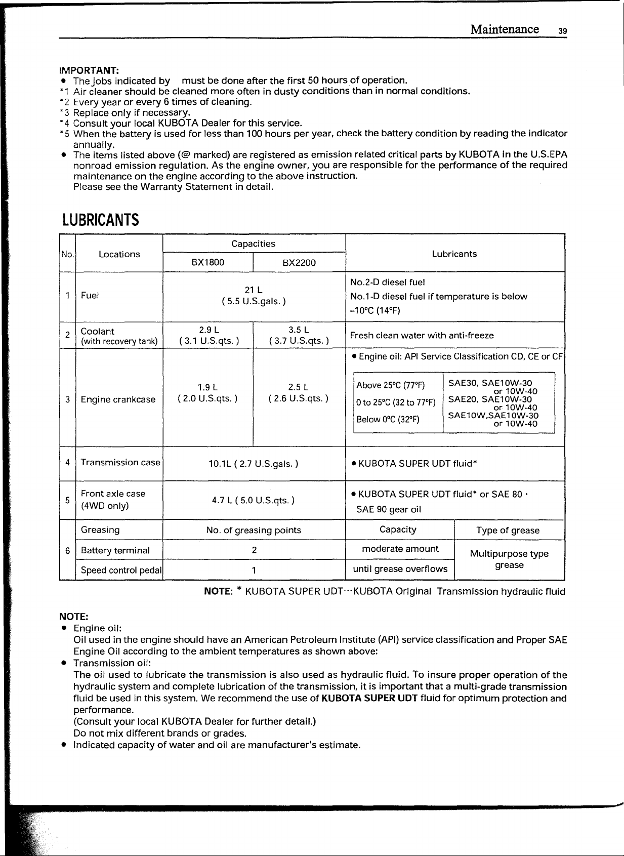
LUBRICANTS
Capacities
No. Locations
BX1800
BX2200
Lubricants
1
Fuel
Coolant
2
(withrecoverytank)
2.9L 3.5 L
(3.1 U.S.qts.) ( 3.7 U.S.qts. )
1.9L 2.5L
Engine crankcase
3
Transmission case
4
Front axle case
5
(4WOonly)
Greasing
Battery terminal 2
6
( 2.0 U.S.qts.) (2.6 U.S.qts.)
10.lL (2.7 U.S.gals.)
4.7 L ( 5.0 U.S.qts.)
No. of greasing points
Speedcontrol pedal
21L
( 5.5U.S.gals. )
1
No.2-0 diesel fuel
No.l-0 diesel fuel if temperature is below
-lO°C (14°F)
Freshcleanwater with anti-freeze
• Engineoil: APIServiceClassificationCO,CEor CF
Above25°e(77°F)
o
to 25°e(32to 77°F)
Below
o-c
(32°F)
SAE30,SAE10W-30
SAE20,SAE10W-30
SAE10W,SAE10W-30
or 10W-40
or 10W-40
or 10W-40
• KUBOTASUPERUOTfluid*
• KUBOTASUPERUOTfluid* or SAE80 •
SAE90gear oil
Capacity
moderate amount
until greaseoverflows
Type of grease
Multipurpose type
grease
NOTE:*KUBOTA SUPERUDT"'KUBOTA Original Transmission hydraulic fluid
NOTE:
• Engine oil:
Oil used in the engine should have an American Petroleum Institute (API)service classification and Proper SAE
Engine Oil according to the ambient temperatures as shown above:
• Transmission oil:
The oil used to lubricate the transmission is also used as hydraulic fluid. To insure proper operation of the
hydraulic system and complete lubrication of the transmission, it is important that a rnultl-qrade transmission
fluid be used in this system. We recommend the use of
KUBOTA SUPER UOT
fluid for optimum protection and
performance.
(Consult your local KUBOTA Dealer for further detail.)
Do not mix different brands or grades.
• Indicated capacity of water and oil are manufacturer's estimate.
Page 2
Maintenance
40
I_PE_R_IO_D_IC_S_ER_V_IC_E _
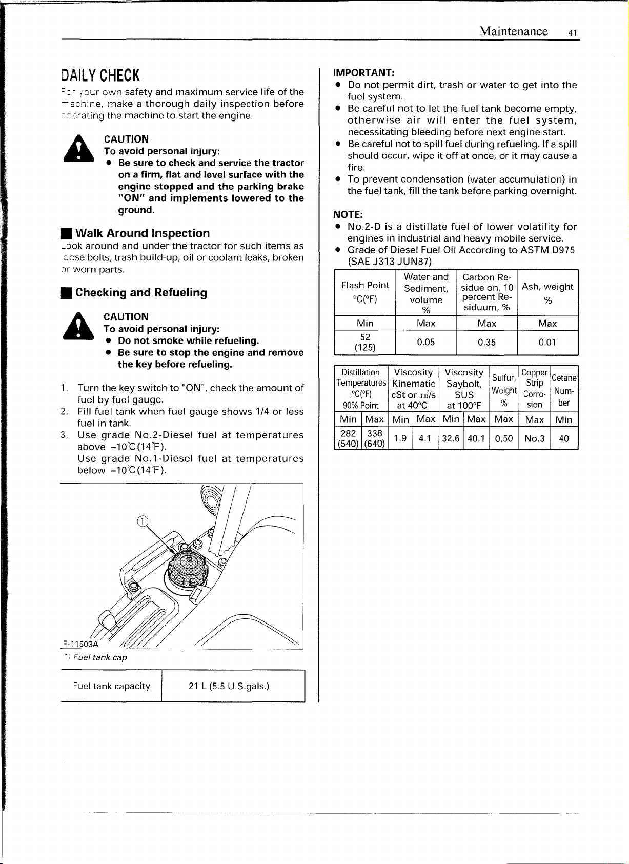
• Engine Cover
CAUTION
To avoid personal injury:
• Do not work under any hydraulically
supported devices. They can settle,
suddenly leak down, or be accidentally
lowered. If necessary to work under
tractor or any machine elements for
servicing or adjustment, securely
support them with stands or suitable
blocking beforehand.
HOW TO OPEN THE HOOD
CAUTION
To avoid personal injury from contact with
moving parts:
• Never open the hood or engine side
cover while the engine isrunning.
• Do not touch muffler or exhaust pipes
while they are hot;
severe burns could result.
To remove the engine cover, remove the bolts, loosen
the nuts and pull forward as indicated by arrows
below.
It
is not necessaryto detachthe engine cover for daily
check.
(1) Bolts
(2) Nuts
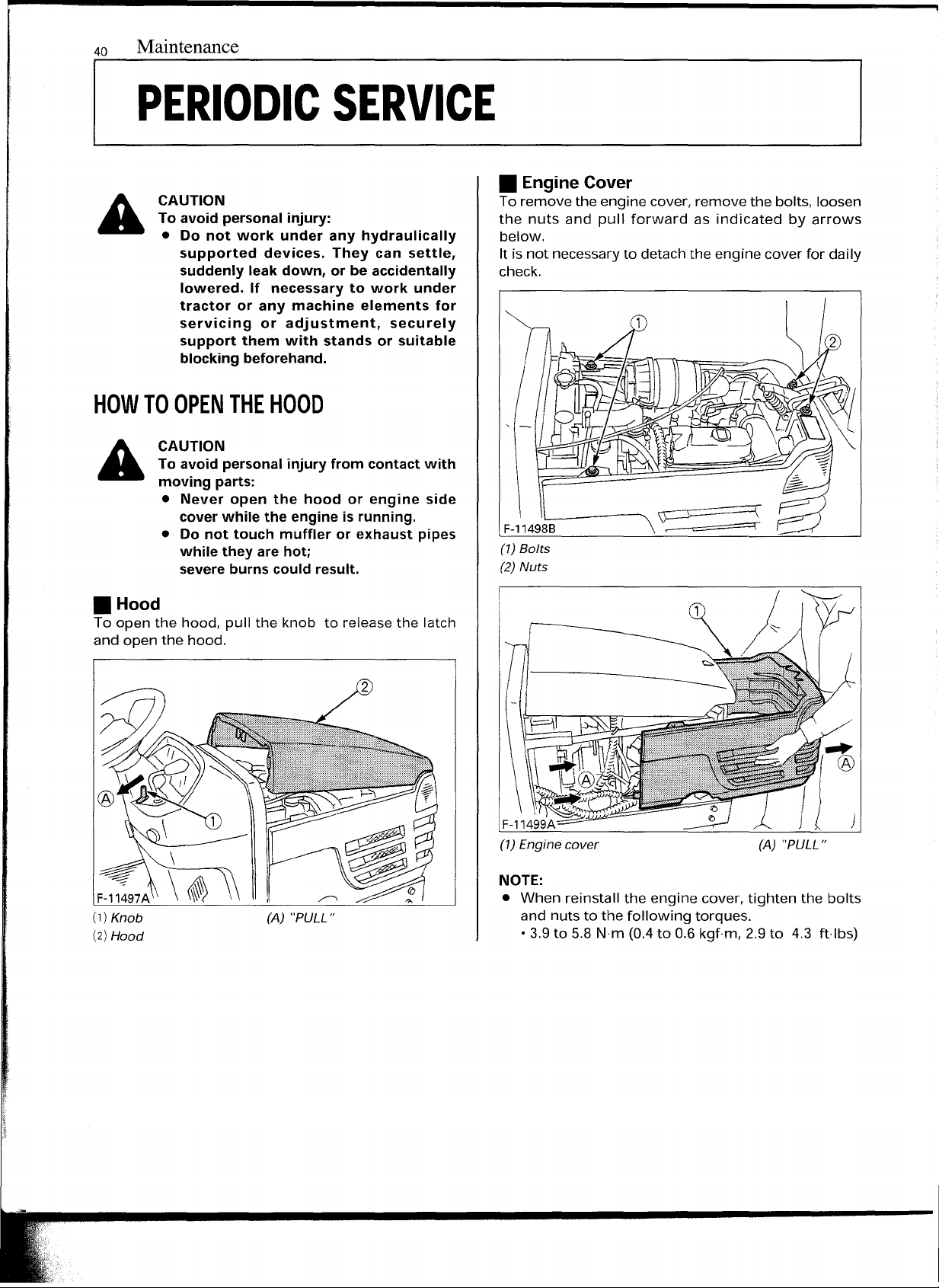
• Hood
To open the hood, pull the knob to release the latch
and open the hood.
(A) "PULL"
(A) "PULL"
NOTE:
• When reinstall the engine cover, tighten the bolts
and nuts to the following torques.
• 3.9to 5.8
Nrn
(0.4to 0.6kgfm, 2.9to 4.3 ftlbs)
Page 3
Maintenance
41
DAILY CHECK
=-:-.:Jur
-;::;hine, make a thorough daily inspection before
::=fating the machine to start the engine.
• Walk Around Inspection
Look around and under the tractor for such items as
oose bolts, trash build-up, oil or coolant leaks, broken
Dr
• Checking and Refueling
1. Turn the key switch to "ON", check the amount of
2. Fill fuel tank when fuel gauge shows
3. Use grade No.2-Diesel fuel at temperatures
own safety and maximum service life of the
CAUTION
To avoid personal injury:
• Be sure to check and service the tractor
on a firm, flat and level surface with the
engine stopped and the parking brake
"ON" and implements lowered to the
ground.
worn parts.
CAUTION
To avoid personal injury:
• Do not smoke while refueling.
• Be sure to stop the engine and remove
the key before refueling.
fuel by fuel gauge.
1/4
fuel in tank.
above -10°C(14°F).
Use grade No.1-Diesel fuel at temperatures
below -10°C(14°F).
or less
IMPORTANT:
• Do not permit dirt, trash or water to get into the
fuel system.
• Be careful not to let the fuel tank become empty,
otherwise air will enter the fuel system,
necessitating bleeding before next engine start.
• Be careful not to spill fuel during refueling. If a spill
should occur, wipe it off at once, or it may cause a
fire.
• To prevent condensation (water accumulation) in
the fuel tank, fill the tank before parking overnight.
NOTE:
• No.2-D is a distillate fuel of lower volatility for
engines in industrial and heavy mobile service.
• Grade of Diesel Fuel Oil According to ASTM 0975
(SAEJ313 JUN87)
FlashPoint
Water and
Sediment,
°C(°F)
Min Max
52
(125)
Distillation
Temperatures
,°C(°F)
Viscosity
Kinematic Saybolt,
cSt or mnfls
90%Point at 40°C
Min Max
282 338
(540)
(640)
Min
1.9 4.1
volume
%
0.05
Max Min
Carbon Re-
sidue on, 10
Ash, weight
percent Re-
siduum,
%
Max
0.35 0.01
Viscosity
SUS
at 100°F
Max
Sulfur,
Weight
%
Max
Copper
Strip
Corro-
sian
Max Min
32.6 40.1 0.50 No.3
%
Max
Cetane
Num-
ber
40
~-11503A ~
- Fuel tank cap
Fueltank capacity
21L(5.5U.S.gals.)
_._------
Page 4
42
Maintenance
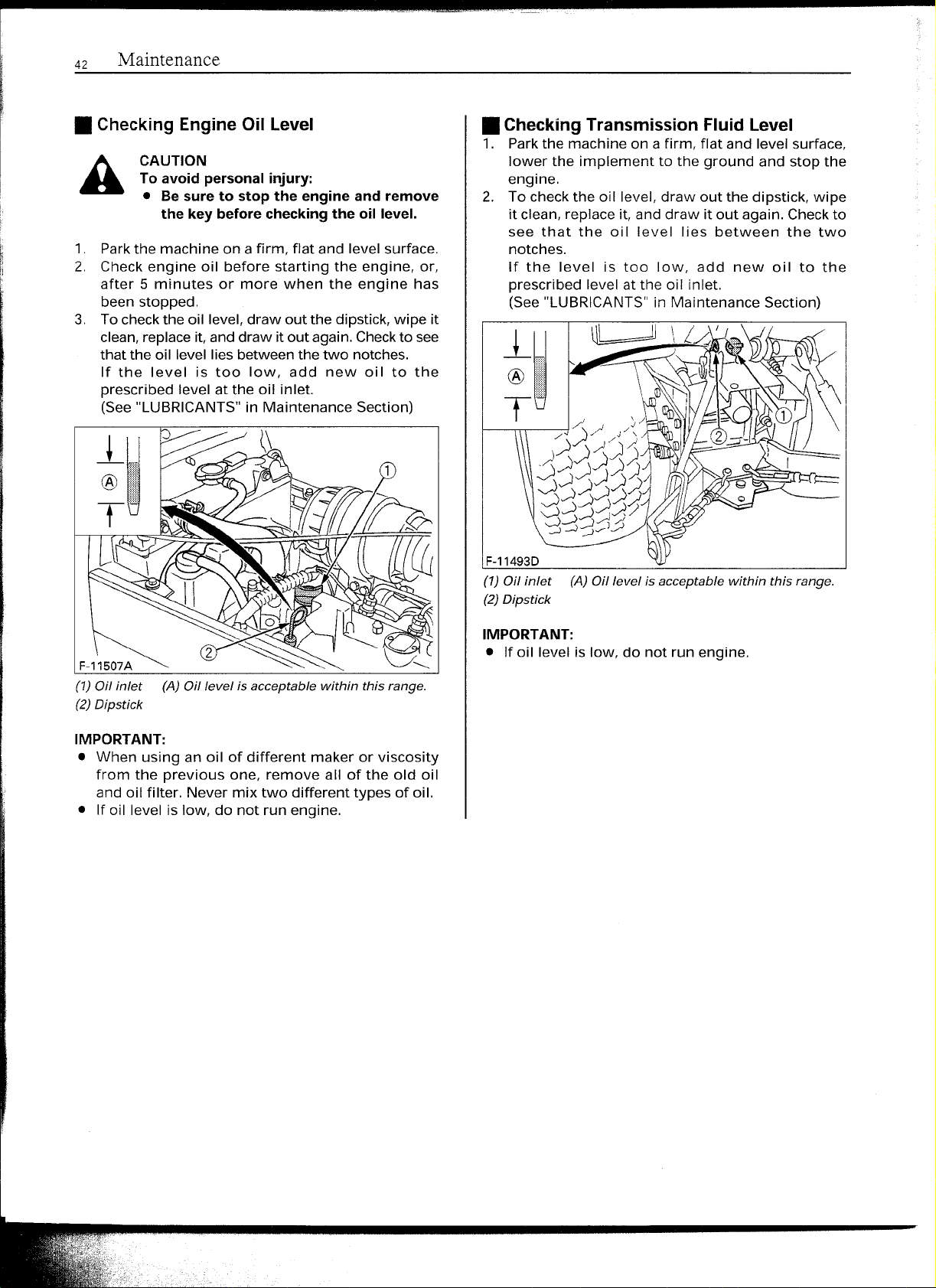
• Checking Engine Oil Level
CAUTION
To avoid personal injury:
• Be sure to stop the engine and remove
the key before checking the oil level.
1. Parkthe machine on a firm, flat and level surface.
2. Check engine oil before starting the engine, or,
after 5 minutes or more when the engine has
been stopped.
3.
To
checkthe oil level,draw out the dipstick,wipe it
clean,replaceit, anddraw it out again. Checkto see
that the oil level lies between the two notches.
If the level is too low, add new oil to the
prescribed level at the oil inlet.
(See"LUBRICANTS"in Maintenance Section)
• Checking Transmission Fluid Level
1. Parkthe machine on afirm, flat and level surface,
lower the implement to the ground and stop the
engine.
2.
To
checkthe oil level, draw out the dipstick, wipe
it clean, replace it, and draw it out again. Checkto
see that the oil level lies between the two
notches.
If the level is too low, add new oil to the
prescribed level atthe oil inlet.
(See"LUBRICANTS"in Maintenance Section)
F-11493D
(1) Oil inlet (A) Oil level is acceptable within this range.
(2)Dipstick
F-11507A
(1)Oil inlet (A) Oil level is acceptable within this range.
(2)Dipstick
IMPORTANT:
• When using an oil of different maker or viscosity
from the previous one, remove all of the old oil
and oil filter. Never mix two different types of oil.
• If oil level is low, do not run engine.
IMPORTANT:
• If oil level is low, do not run engine.
Page 5
Maintenance 43
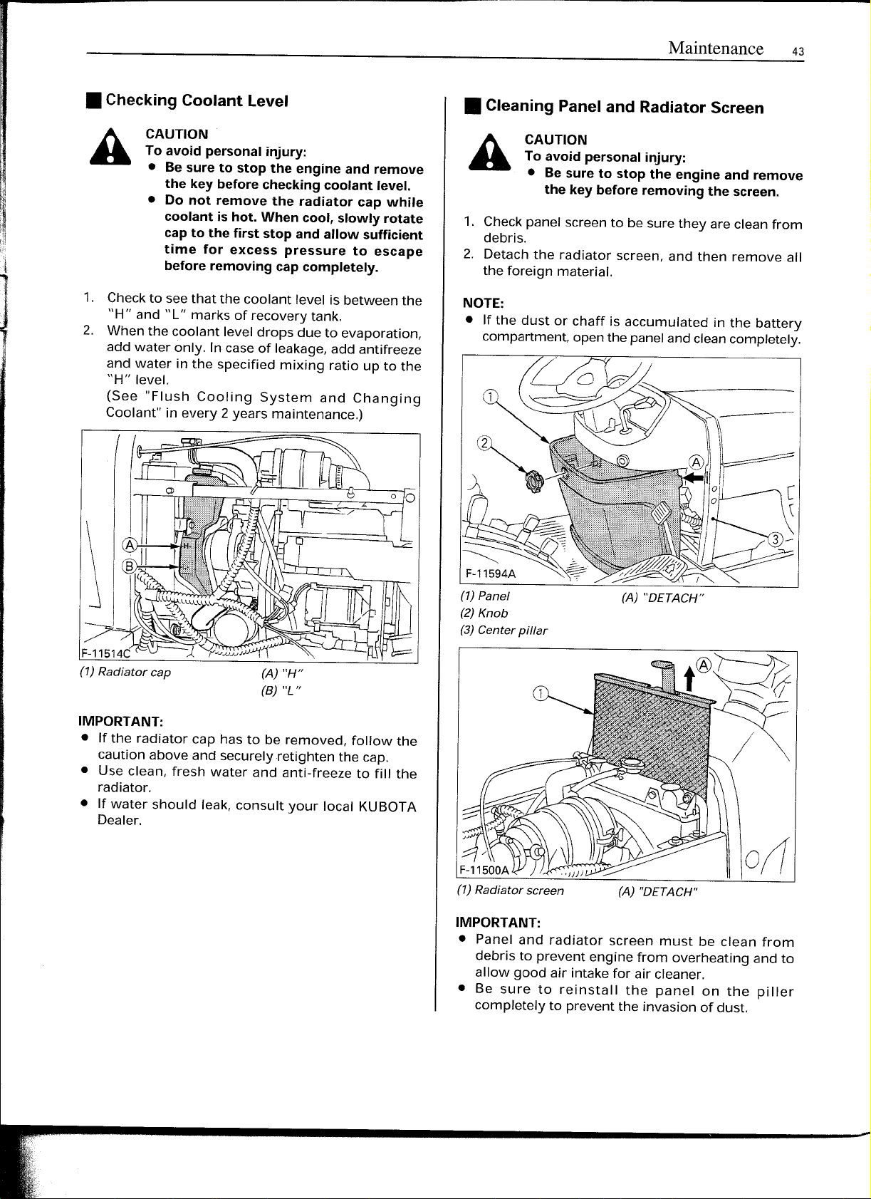
• Checking Coolant Level
CAUTION
A
1. Checkto seethat the coolant level is between the
2. When the coolant level drops due to evaporation,
To avoid personal injury:
• Besure to stop the engine and remove
the key before checking coolant level.
• Do not remove the radiator cap while
coolant is hot. When cool, slowly rotate
cap to the first stop and allow sufficient
time for excess pressure to escape
before removing cap completely.
"H" and "L" marks of recovery tank.
add water only. In caseof leakage,add antifreeze
and water in the specified mixing ratio up to the
"H" level.
(See "Flush Cooling System and Changing
Coolant" in every 2 years maintenance.)
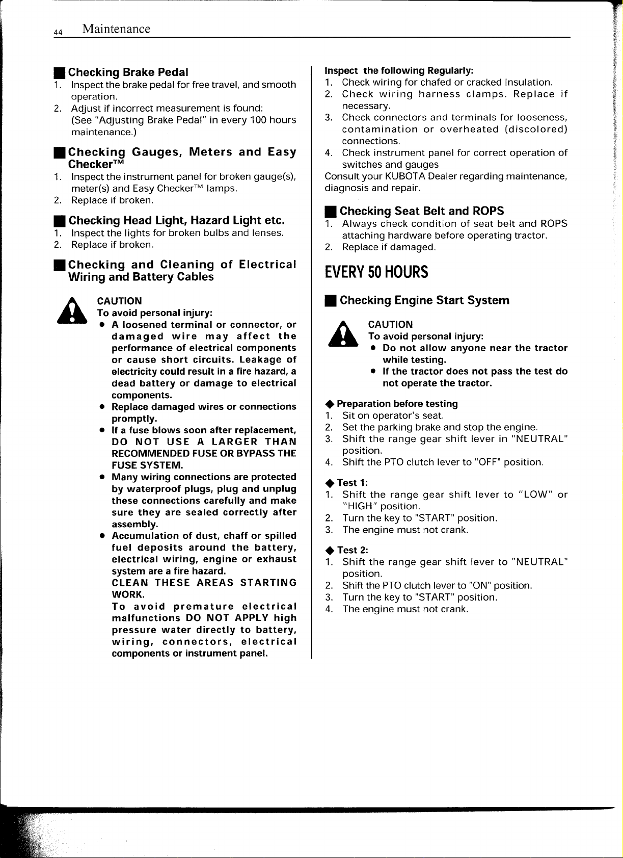
• Cleaning Panel and Radiator Screen
CAUTION
A
1. Checkpanel screento be sure they are clean from
2. Detach the radiator screen, and then remove all
NOTE:
• If the dust or chaff is accumulated in the battery
To avoid personal injury:
• Besure to stop the engine and remove
the key before removing the screen.
debris.
the foreign material.
compartment,openthe panelandcleancompletely.
(A) "H"
(B) "L"
IMPORTANT:
• If the radiator cap has to be removed, follow the
caution above and securelyretighten the cap.
• Use clean, fresh water and anti-freeze to fill the
radiator.
• If water should leak, consult your local KUBOTA
Dealer.
(1) Panel
(2)
Knob
(3) Center pillar
(A) "DETACH"
0((
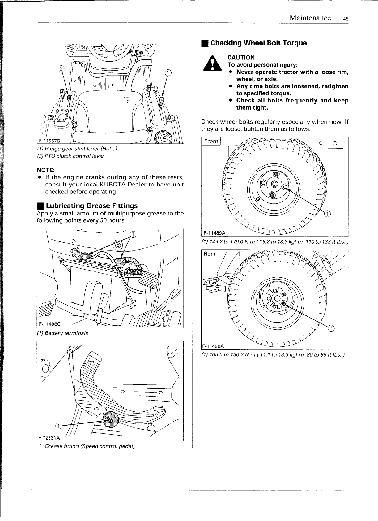
(1) Radiator screen
IMPORTANT:
• Panel and radiator screen must be clean from
debris to prevent engine from overheating and to
allow good air intake for air cleaner.
• Be sure to reinstall the panel on the piller
completely to prevent the invasion of dust.
(A) "DETACH"
Page 6
44
Maintenance
• Checking Brake Pedal
1. Inspectthe brakepedalfor freetravel, and smooth
operation.
2. Adjust if incorrect measurement is found:
(See"Adjusting Brake Pedal" in every 100hours
maintenance.)
• Checking Gauges, Meters and Easy
Checker"
1. Inspectthe instrument panel for broken gauge(s),
meter(s) and Easy
2. Replaceif broken.
Checker"
lamps.
• Checking Head Light, Hazard Light etc.
1. Inspect the lights for broken bulbs and lenses.
2. Replaceif broken.
• Checking and Cleaning of Electrical
Wiring and Battery Cables
CAUTION
A
To avoid personal injury:
• A loosened terminal or connector, or
damaged wire may affect the
performance of electrical components
or cause short circuits. Leakage of
electricity could result in a fire hazard,a
dead battery or damage to electrical
components.
• Replacedamaged wires or connections
promptly.
• If a fuse blows soon after replacement,
DO NOT USE A LARGER THAN
RECOMMENDEDFUSEORBYPASSTHE
FUSESYSTEM.
• Many wiring connections are protected
by waterproof plugs, plug and unplug
these connections carefully and make
sure they are sealed correctly after
assembly.
• Accumulation of dust, chaff or spilled
fuel deposits around the battery,
electrical wiring, engine or exhaust
system area fire hazard.
CLEAN THESE AREAS STARTING
WORK.
To avoid premature electrical
malfunctions DO NOT APPLY high
pressure water directly to battery,
wiring, connectors, electrical
components or instrument panel.
Inspect the following Regularly:
1. Checkwiring for chafed or cracked insulation.
2. Check wiring harness clamps. Replace if
necessary.
3. Check connectors and terminals for looseness,
contamination or overheated (discolored)
connections.
4. Check instrument panel for correct operation of
switches and gauges
Consultyour KUBOTADealerregarding maintenance,
diagnosis and repair.
• Checking Seat Belt and ROPS
1. Always check condition of seat belt and RaPS
attaching hardware before operating tractor.
2. Replaceif damaged.
EVERY 50 HOURS
• Checking Engine Start System
CAUTION
A
• Preparation before testing
1. Sit on operator's seat.
2. Set the parking brake and stop the engine.
3. Shift the range gear shift lever in "NEUTRAL"
4. Shift the PTOclutch lever to "OFF"position.
• Test 1:
1. Shift the range gear shift lever to "LOW" or
2. Turn the key to "START" position.
3. The engine must not crank.
• Test
1. Shift the range gear shift lever to "NEUTRAL"
2. Shiftthe PTOclutch leverto "ON"position.
3. Turn the key to "START"position.
4. The engine must not crank.
To avoid personal injury:
• Do not allow anyone near the tractor
while testing.
• If the tractor does not pass the test do
not operate the tractor.
position.
"HIGH" position.
2:
position.
Page 7
II
F-11557D
(1)Range gear shift lever (Hi-La)
(2)PTOclutch control lever
NOTE:
• If the engine cranks during any of these tests,
consult your local KUBOTA Dealer to have unit
checkedbefore operating .
Maintenance 45
• Checking Wheel Bolt Torque
CAUTION
To avoid personal injury:
• Never operate tractor with a loose rim,
wheel, or axle.
• Any time bolts are loosened, retighten
to specifiedtorque.
• Check all bolts frequently and keep
them tight.
Checkwheel bolts regularly especially when new. If
they are loose, tighten them asfollows.
Front
o
0
• lubricating Grease Fittings
Apply a small amount of multipurpose grease to the
following points every 50hours.
(1) Battery terminals
9)
/
\
F-11489A
(1) 149.2 to 179.0
F-11490A
(1) 108.5 to 130.2
Nim
(15.2 to 18.3 kgf.m, 110 to 132fUbs.)
Nirn
(11.1 to 13.3 kgf.m, 80 to 96
tttbs.}
=-02531:
o
Grease fitting (Speed control pedal)
11/
~~-
----~--- --- ----
-0_(
Page 8
46 Maintenance
EVERY 100 HOURS
• Battery
DANGER
A
A
Mishandling the battery shortens the service life and
addsto maintenancecosts.
The original battery is maintenance free, but needs
some servicing.
If the battery is weak, the engine will be difficult to
start and the lights will be dim. Itis important to check
the battery periodically.
Toavoid the possibility of battery explosion:
For the refillable type battery, follow the
instructions below.
• Do not use or charge the refillable type
battery if the fluid level is below the
LOWER (lower limit level) mark.
Otherwise, the battery component
parts may prematurely deteriorate,
which may shorten the battery's service
life or cause an explosion. Check the
fluid level regularly and add distilled
water as required so that the fluid level
is between the UPPER and LOWER
levels.
CAUTION
To avoid personal injury:
• Never remove the vent caps while the
engine is running.
• Keep electrolyte away from eyes, hands
and clothes. If you are spattered with it,
wash it away completely with water
immediately and get medical attention.
• Wear eye protection and rubber gloves
when working around the battery.
• How to readthe indicator (65D23L,75D23L)
Checkthe battery condition by reading the indicator
Stateof indicatordisplay
Green
Black
White
When the indicator turns white, do not charge the
battery but replace it with new one.
• Battery Charging
A
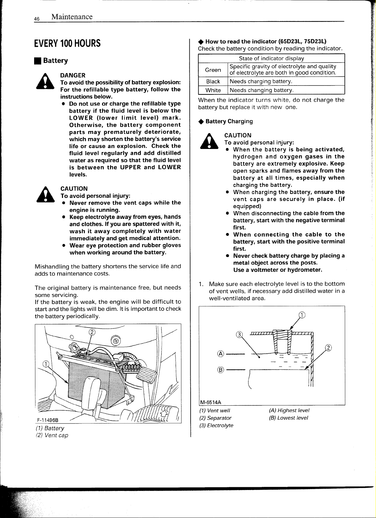
1. Make sure each electrolyte level isto the bottom
of vent wells, if necessaryadd distilled water in a
well-ventilated area.
Specificgravityof electrolyteandquality
of electrolyteareboth ingoodcondition.
Needschargingbattery.
Needschangingbattery.
CAUTION
To avoid personal injury:
• When the battery is being activated,
hydrogen and oxygen gases in the
battery are extremely explosive. Keep
open sparks and flames away from the
battery at all times, especially when
charging the battery.
• When charging the battery, ensure the
vent caps are securely in place. (if
equipped)
• When disconnecting the cable from the
battery, start with the negative terminal
first.
• When connecting the cable to the
battery, start with the positive terminal
first.
• Nevercheck battery charge by placing a
metal object acrossthe posts.
Usea voltmeter or hydrometer.
(1) Battery
(2)
Vent cap
@--
@--
M-6514A
(1) Vent well
(2) Separator
(3) Electrolyte
3
2
(A) Highest level
(B) Lowest level
Page 9
Maintenance
47
The water in the electrolyte evaporates during
recharging. Liquid shortage damages the battery.
Excessive liquid spills over and damages the
tractor body.
3. To slow charge the battery, connect the battery
positive terminal to the charger positive terminal
and the negative to the negative, then recharge in
the standard fashion.
4. A boost charge is only for emergencies. It will
partially charge the battery at a high rate and in a
short time.
When using a boost-charged battery, it is necessary
to recharge the battery as early as possible.
Failure to do this will shorten the battery's
service life.
5. When the specific gravity of electrolyte is between
1.27and 1.29the charging is completed.
6. Whenexchanging an old battery for a new one, use
battery of equal specification shown in
Table 1.
Table 1
Tractor Battery
Type
BX1800
Type
26/26R
65D23L•
526RA 12
BX2200
75D23L•
(V)
Reserve
Capacity
(min)
Volts
12 62
12 111
12
80
90
Cold
Cranking
Amps
435
490
535
550
• :with the indicator
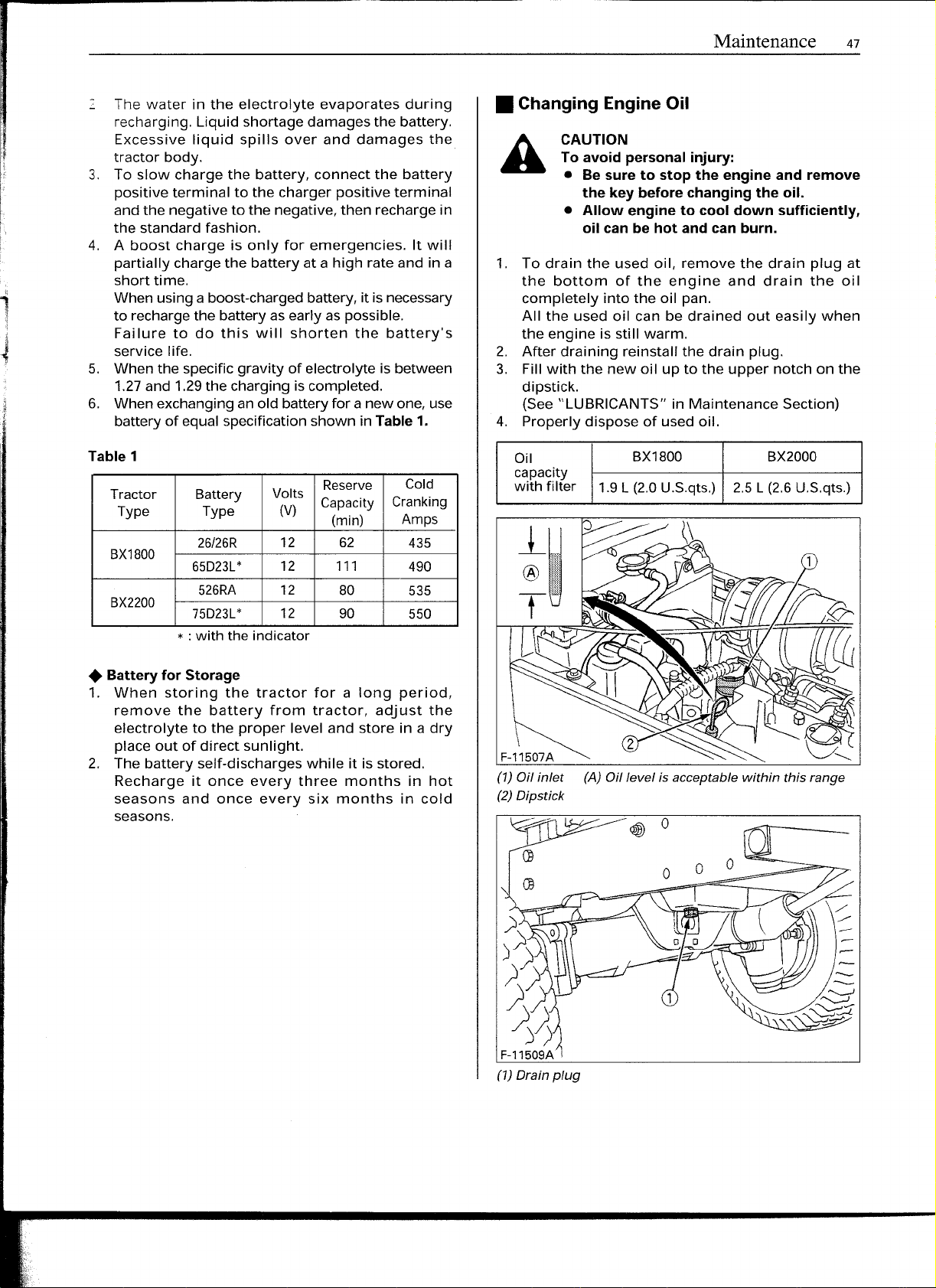
• Changing Engine Oil
CAUTION
To avoid personal injury:
• Be sure to stop the engine and remove
the key before changing the oil.
• A"ow engine to cool down sufficiently,
oil can be hot and can burn.
1. To drain the used oil, remove the drain plug at
the bottom of the engine and drain the oil
completely into the oil pan.
All the used oil can be drained out easily when
the engine is still warm.
2. After draining reinstall the drain plug.
3.
Fill
with the new oil up to the upper notch on the
dipstick.
(See "LUBRICANTS" in Maintenance Section)
4. Properly dispose of used oil.
Oil
capacity
with filter
BX1800
1.9L (2.0U.S.qts.) 2.5 L (2.6U.S.qts.)
BX2000
• Battery for Storage
1. When storing the tractor for a long period,
remove the battery from tractor, adjust the
electrolyte to the proper level and store in a dry
place out of direct sunlight.
2. The battery self-discharges while it is stored.
Recharge it once every three months in hot
seasons and once every six months in cold
seasons.
F-11507A
(1) Oil inlet (A) Oil levelisacceptable within this range
(2) Dipstick
- 0
c$
(1) Drain plug
Page 10
48
Maintenance
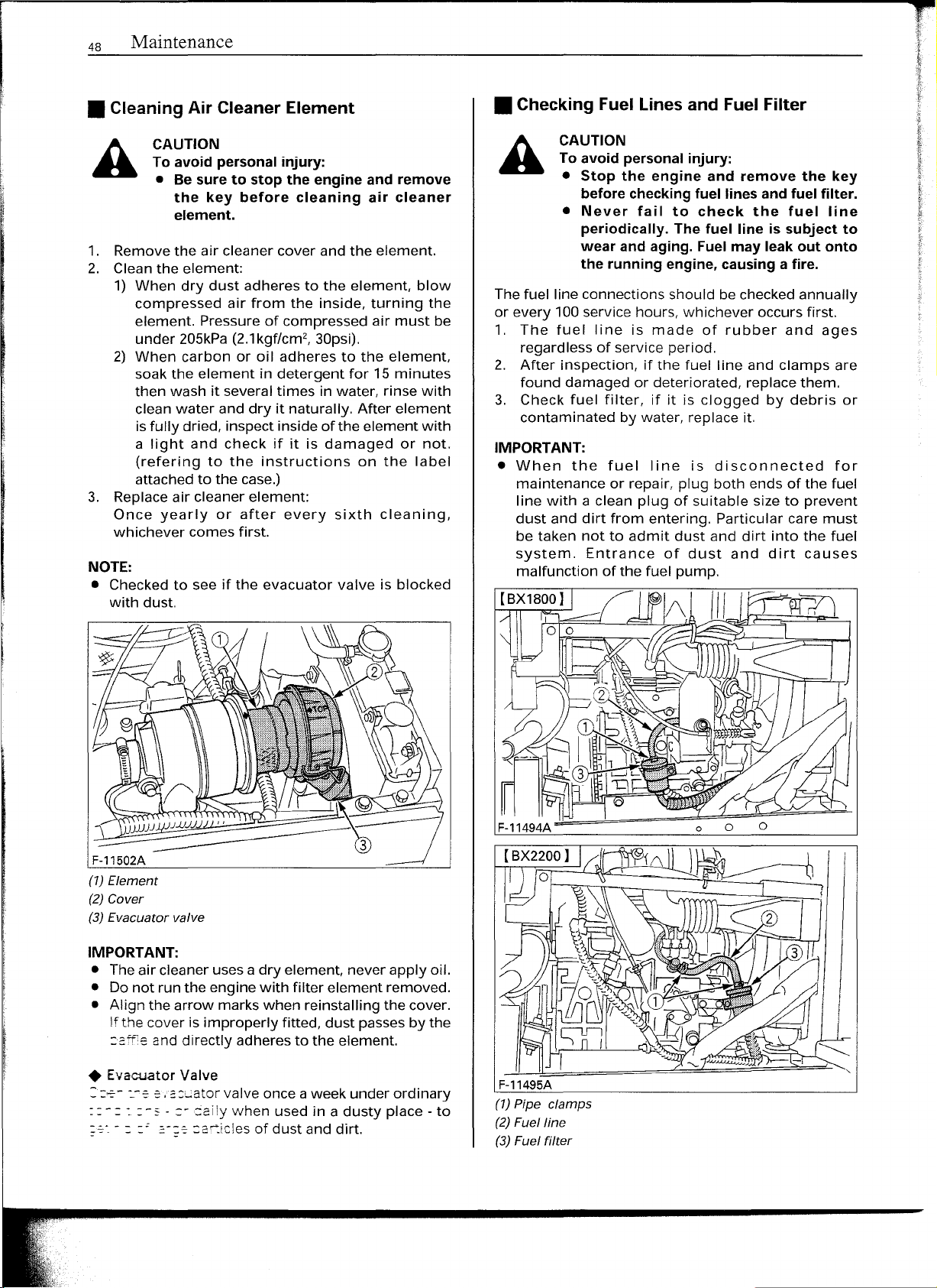
• Cleaning Air Cleaner Element
CAUTION
To avoid personal injury:
• Be sure to stop the engine and remove
the key before cleaning air cleaner
element.
1. Removethe air cleaner cover and the element.
2. Clean the element:
1) When dry dust adheres to the element, blow
compressed air from the inside, turning the
element. Pressure of compressed air must be
under 205kPa(2.1
2) When carbon or oil adheres to the element.
soak the element in detergent for 15 minutes
then wash it several times in water, rinse with
clean water and dry it naturally. After element
isfully dried, inspect inside of the element with
a light and check if it is damaged or not.
(refering to the instructions on the label
attached to the case.)
3. Replaceair cleaner element:
Once yearly or after every sixth cleaning,
whichever comes first.
NOTE:
• Checked to see if the evacuator valve is blocked
with dust.
kgf/cm2,
30psi).
• Checking Fuel Lines and Fuel Filter
CAUTION
To avoid personal injury:
• Stop the engine and remove the key
before checking
• Never fail to check the fuel line
periodically. The fuel line is subject to
wear and aging. Fuel may leak out onto
the running engine, causing a fire.
The fuel line connections should becheckedannually
or every 100service hours, whichever occurs first.
1. The fuel line is made of rubber and ages
regardless of service period.
2. After inspection, if the fuel line and clamps are
found damaged or deteriorated, replace them.
3. Check fuel filter, if it is clogged by debris or
contaminated by water, replace it.
IMPORTANT:
• When the fuel line is disconnected for
maintenance or repair, plug both ends of the fuel
line with a clean plug of suitable size to prevent
dust and dirt from entering. Particular care must
be taken not to admit dust and dirt into the fuel
system. Entrance of dust and dirt causes
malfunction of the fuel pump.
fuel lines
and fuel filter.
F-11502A
(1) Element
(2) Cover
(3) Evacuator valve
IMPORTANT:
• The air cleaner usesa dry element, never apply oil.
• Donot run the engine with filter element removed.
• Align the arrow marks when reinstalling the cover.
Ifthe cover is improperly fitted, dust passesby the
::aff1eand directly adheres to the element.
• Evacuator Valve
::::-=--
-:.-ee
.acuator
::-:: :-" - :- Gailywhen used in a dusty place - to
~-- - - -- .:-;e
valve once aweek under ordinary
:a!:.icles of dust and dirt.
Page 11
Maintenance 49
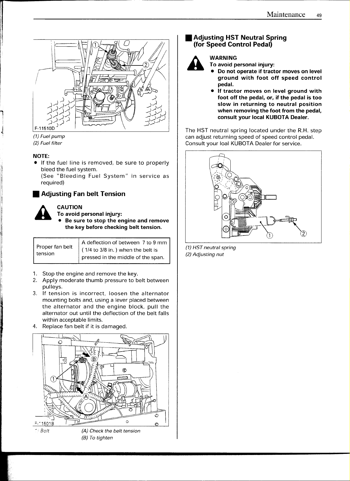
• Adjusting HST Neutral Spring
(for Speed Control Pedal)
WARNING
To avoid personal injury:
• Do not operate if tractor moves on level
ground with foot off speed control
pedal.
• If tractor moves on level ground with
foot off the pedal, or, if the pedal is too
slow in returning to neutral position
1
The HST neutral spring located under the R.H.step
(1)Fuel pump
(2)Fuel filter
NOTE:
• If the fuel line is removed, be sure to properly
bleed the fuel system.
(See "Bleeding Fuel System" in service as
required)
can adjust returning speed of speed control pedal.
Consult your loal KUBOTADealer for service.
when removing the foot from the pedal,
consult your local KUBOTA Dealer.
• Adjusting Fan belt Tension
CAUTION
To avoid personal injury:
• Be sure to stop the engine and remove
the key before checking belt tension.
Properfanbelt
tension
1. Stop the engine and remove the key.
2. Apply moderate thumb pressure to belt between
pulleys.
3. If tension is incorrect, loosen the alternator
mounting bolts and, using a lever placed between
the alternator and the engine block, pull the
alternator out until the deflection of the belt falls
within acceptablelimits.
4. Replacefan belt if it is damaged.
A deflectionof between 7to 9 mm
( 1/4to3/8
pressedin the middle of the span.
in.) whenthe belt is
(1) HST neutral spring
(2)Adjusting nut
(A) Check the belt tension
(B) To tighten
Page 12
50
Maintenance
• Adjusting Brake Pedal
CAUTION
A
Properbrake
pedalfreetravel
1. Releasethe parking brake.
2. Loosen the RH lock nut and extend the RH
3. Loosen the LH lock nut and turn the LH
4. Retighten the LH lock nut.
5. Adjust the RHrod length so that the brake pedal
6. Extend the RHturnbuckle one additional turn.
7. Retighten the RHlock nut.
8. Depress the brake pedal several times and make
To avoid personal injury:
• Stop the engine,remove the key, lower the
implement to the ground, and chock the
wheels beforecheckingbrakepedal.
• Evenifthe
the limitation, adjust the brake pedal
following the procedurebelow.
• If you are not able to adjust, consult your
localKUBOTADealer.
turnbuckle to the end of the thread.
turnbuckle to adjust the LH rod length so that the
brake pedal free travel is 20 mm (13/16in.).
free travel is 10mm (7/16 in.).
sure the brake pedal free travel is from 20 to 30
mm (13/16to 1-3/16in.).
brake pedal free travel iswithin
20to 30mm (13/16to 1·3/16in.)
onthe pedal
EVERY 200 HOURS
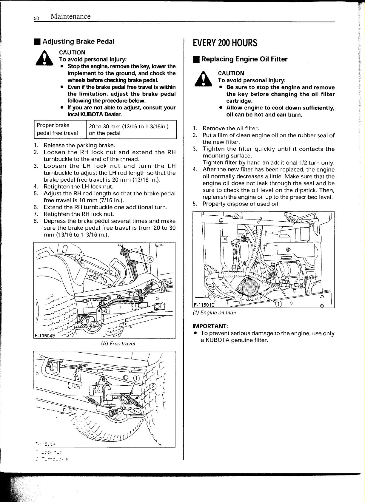
• Replacing Engine Oil Filter
CAUTION
A
1. Remove the oil filter.
2. Puta film of clean engine oil on the rubber sealof
3. Tighten the filter quickly until it contacts the
4. After the new filter has been replaced, the engine
5. Properly dispose of used oil.
To avoid personal injury:
• Be sure to stop the engine and remove
the key before changing the oil filter
cartridge.
• Allow engine to cool down sufficiently,
oil can be hot and can burn.
the new filter.
mounting surface.
Tighten filter by hand an additional 1/2turn only.
oil normally decreasesa little. Make sure that the
engine oil does not leak through the seal and be
sure to check the oil level on the dipstick. Then,
replenishthe engine oil up to the prescribedlevel.
(A)
Free travel
!:::::
I
~'=j~~L:<'))
F-11501C
(1)Engine oil filter
IMPORTANT:
• To prevent serious damage to the engine, use only
a KUBOTAgenuine filter.
Page 13
Maintenance 51
• Checking Radiator Hose and Clamp
CAUTION
To avoid personal injury:
• Be sure to stop the engine and remove
the key before checking radiator hose
and clamp.
Checkto see if radiator hoses are properly secured
every 200 hours of operation or six months,
whichever comes first.
1. If hose clamps are loose or water leaks, tighten
bands securely.
2. Replacehosesandtighten hoseclamps securely,if
radiator hosesareswollen, hardenedor cracked.
3. Properly dispose of used coolant.
Replace hoses and hose clamps every 2 years or
earlier if checked and found that hoses are swollen,
hardenedor cracked.
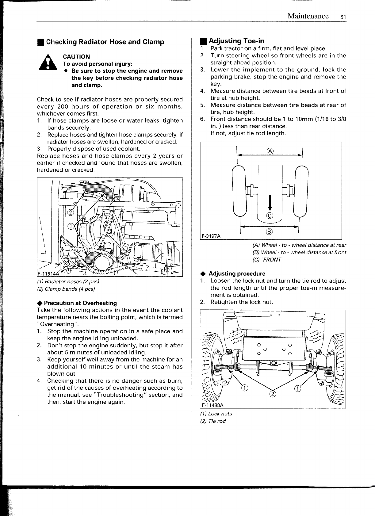
• Adjusting Toe-in
1. Parktractor on afirm, flat and level place.
2. Turn steering wheel so front wheels are in the
straight ahead position.
3. Lower the implement to the ground, lock the
parking brake, stop the engine and remove the
key.
4. Measure distance between tire beads at front of
tire at hub height.
S.
Measure distance between tire beads at rear of
tire, hub height.
6. Front distance should be 1to 10mm
in. ) lessthan rear distance.
If not, adjust tie rod length.
®
(1/16to318
..I
• Precaution at Overheating
Takethe following actions in the event the coolant
temperature nearsthe boiling point, which is termed
"Overheating" .
1. Stop the machine operation in a safe place and
keepthe engine idling unloaded.
2. Don't stop the engine suddenly, but stop it after
aboutSminutes of unloaded idling.
3. Keepyourself well away from the machine for an
additional 10 minutes or until the steam has
blown out.
4. Checking that there is no danger such as burn,
get rid of the causesof overheating according to
the manual, see "Troubleshooting" section, and
then, start the engine again.
F-3197A
(A) Wheel - to - wheel distance at rear
(B) Wheel - to - wheel distance at front
(C) "FRONT"
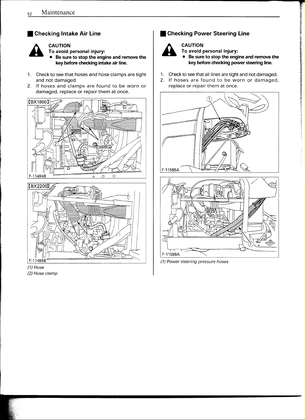
• Adjusting procedure
1. Loosen the lock nut and turn the tie rod to adjust
the rod length until the proper toe-in measure-
ment isobtained.
2. Retightenthe lock nut.
o
0
o
o
o
0
0
0
Page 14
52
Maintenance
• Checking Intake Air line
CAUTION
To avoid personal injury:
• Be sure to stop the engine and remove the
key before checking intake air line.
1. Checkto seethat hoses and hose clamps aretight
and not damaged.
2.
If
hoses and clamps are found to be worn or
damaged, replace or repair them at once.
• Checking Power Steering line
CAUTION
To avoid personal injury:
• Be sure to stop the engine and remove the
key before checking power steering line.
1. Checkto seethat all linesaretight andnot damaged.
2.
If
hoses are found to be worn or damaged,
replace or repair them at once.
F-11595A
,._-.-:::::::=:;;;:::::::.:::":7------'\
F-11596A
(1) Power steering pressure hoses
Page 15
Maintenance
53
I
~
If
Iii
EVERY 300 HOURS
• Changing Transmission Fluid
CAUTION
A
1
2.
3.
4.
:
11
5.
6.
To avoid personal injury:
• Allow engine to cool down sufficiently,
oil can be hot and can burn.
To drain the used oil, remove the drain plug at
the bottom of the transmission caseand drain the
oil completely into the oil pan.
After draining reinstall the drain plug.
Cleanthe transmission strainer.
Fill with new KUBOTASUPERUDTfluid up to the
upper notch on the dipstick.
(See "LUBRICANTS" and "DAILY CHECK" in
Maintenance Section)
After running the engine for a few minutes, stop
it and check the oil level again, add oil to
prescribed level.
Properly dispose of used oil.
10.1L (2.7 U.S.gals.)Oilcapacity
IMPORTANT:
• Do not operate the tractor immediately after
changing the transmission fluid .
Run the engine at medium speed for a few
minutes to prevent damage to the transmission.
• Cleaning Transmission Strainer
When changing the transmission fluid, disassemble
and rinse the strainer with nonflammable solvent to
completely clean off filings.
When reassembling be careful not to damage the
parts.
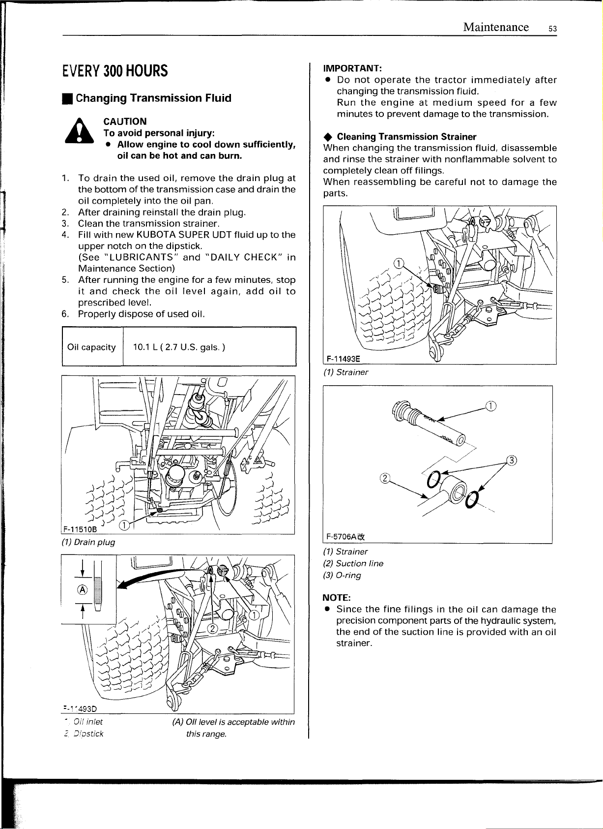
F-11493E
(1) Strainer
(1)
Drain plug
• Oil
2.
[Jiostick
inlet
(A) Oll
levet is acceptable within
this range.
3
2
F-5706A~
(1)
Strainer
(2)
Suction line
(3) a-ring
NOTE:
• Since the fine filings in the oil can damage the
precisioncomponent parts of the hydraulic system,
the end of the suction line is provided with an oil
strainer.
Page 16
54
Maintenance
• Replacing Transmission Oil Filter
CAUTION
To avoid personal injury:
• Allow engine to cool down sufficiently,
oil can be hot and can burn.
1. Removethe oil filter.
2. Putafilm of cleantransmission oil on rubber seal
of new fiIter.
3. Tighten the filter quickly until it contacts the
mounting surface.
Tighten filter by hand an additional
4. After the new filter has been replaced, the
transmission fluid level will decrease a little.
Make sure that the transmission fluid does not
leakthrough the seal, and checkthe fluid level.
Top up if necessary.
5. Properly dispose of used oil.
1/2
turn only.
.:
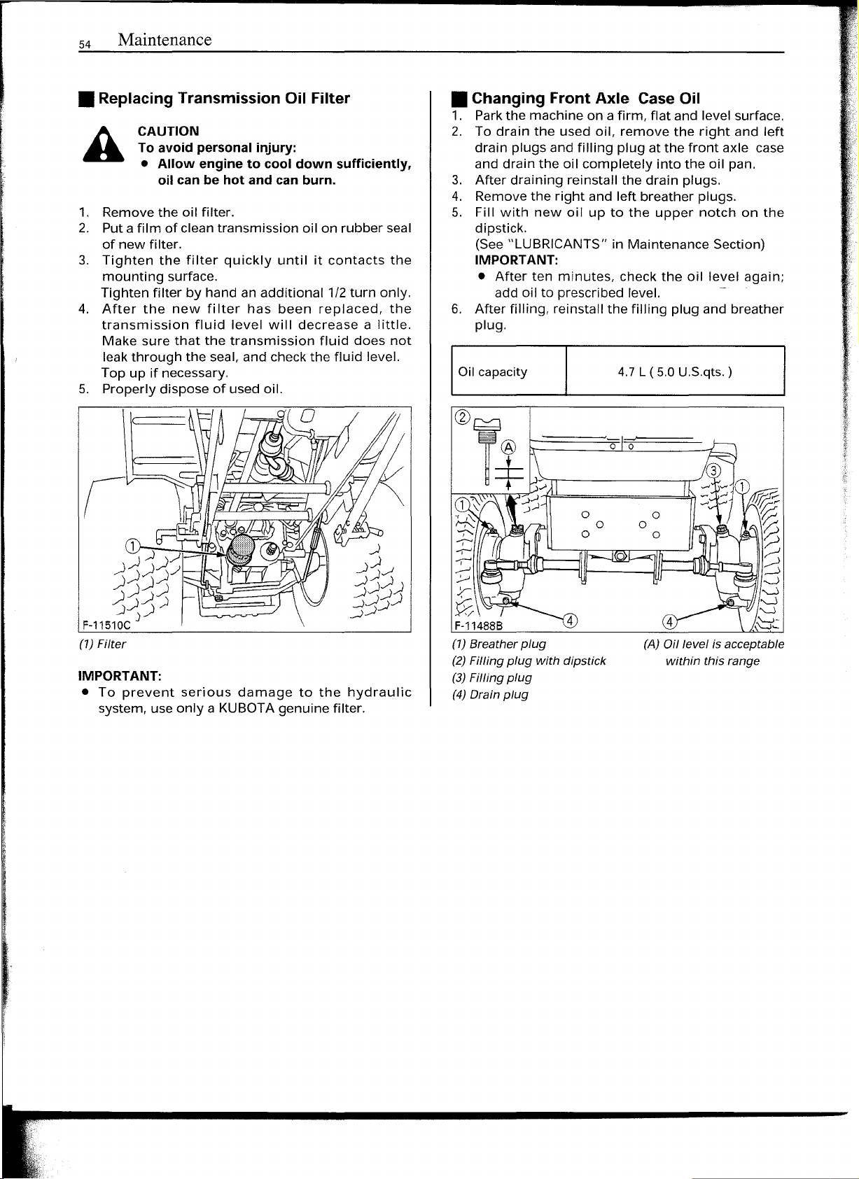
• Changing Front Axle Case Oil
1. Parkthe machine on a firm, flat and level surface.
2. To drain the used oil, remove the right and left
drain plugs and filling plug atthe front axle case
and drain the oil completely into the oil pan.
3. After draining reinstall the drain plugs.
4. Removethe right and left breather plugs.
5. Fill with new oil up to the upper notch on the
dipstick.
(See"LUBRICANTS" in Maintenance Section)
IMPORTANT:
• After ten minutes, check the oil level again;
add oil to prescribed level. -
6. After filling, reinstall the filling plug and breather
plug.
I
Oil
capacity
4.7L(5.0U.S.qts.)
o
0
(1) Filter
IMPORTANT:
• To prevent serious damage to the hydraulic
system, use only a KUBOTAgenuine filter.
o
o
o
o
o
o
(A) Oil level is acceptable
within this range
Page 17
PiERY 400 HOURS
EVERY 1 YEAR
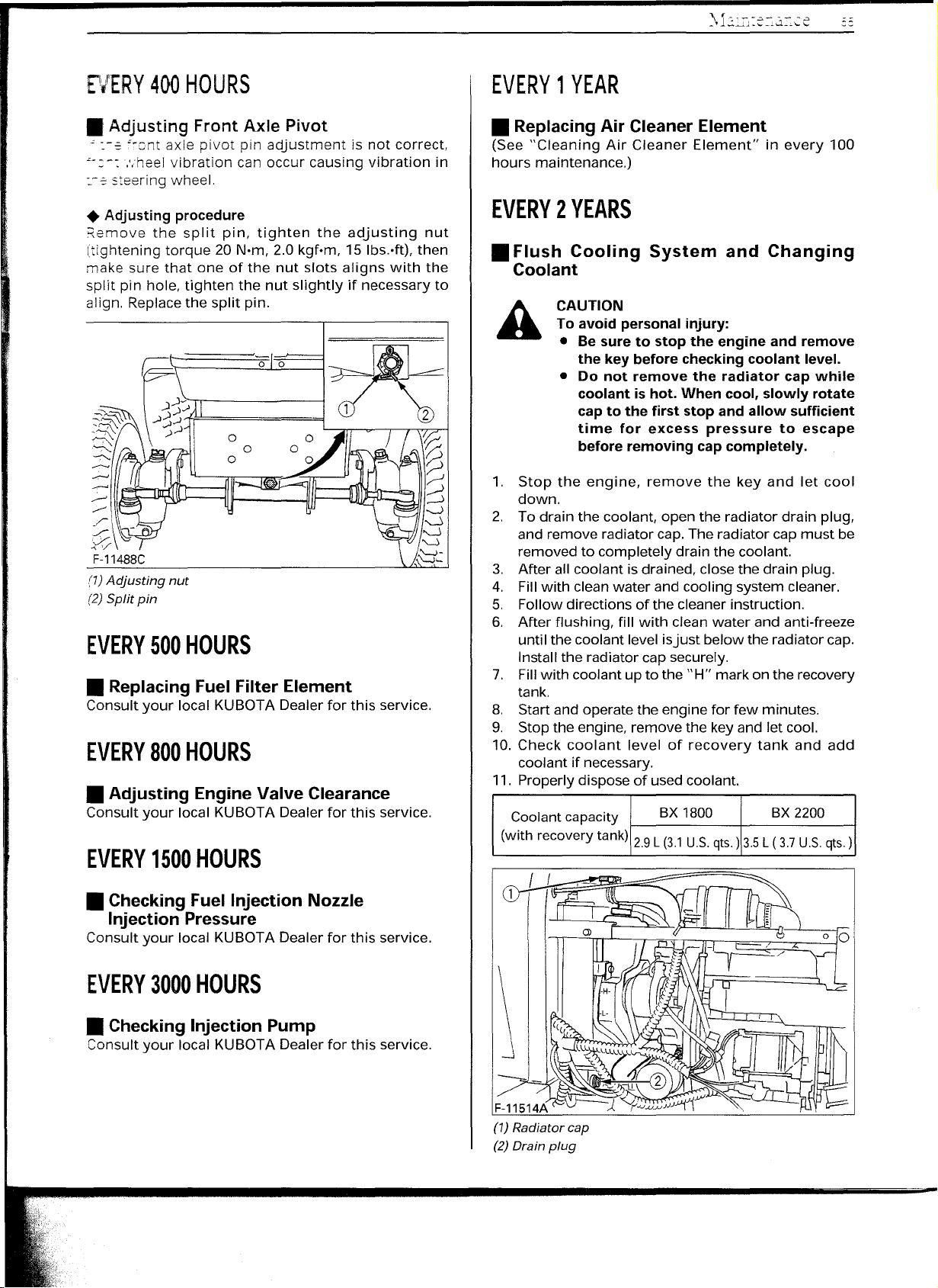
• Adjusting Front Axle Pivot
":-2
~"cnt axle pivot pin adjustment is not correct,
~-:-: :.heel vibration can occur causing vibration in
:-2
steering wheel.
• Adjusting procedure
Remove the split pin, tighten the adjusting nut
Itightening torque 20 N·m, 2.0 kqf-m, 15
make sure that one of the nut slots aligns with the
split pin hole, tighten the nut slightly if necessary to
align. Replacethe split pin.
(7)Acljusting nut
(2)Split pin
lbs.vtt),
then
EVERY 500 HOURS
• Replacing Fuel Filter Element
Consult your local KUBOTA Dealer for this service.
EVERY 800 HOURS
• Adjusting Engine Valve Clearance
Consult your local KUBOTA Dealer for this service.
EVERY 1500 HOURS
• Replacing Air Cleaner Element
(See "Cleaning Air Cleaner Element" in every 100
hours maintenance.)
EVERY 2 YEARS
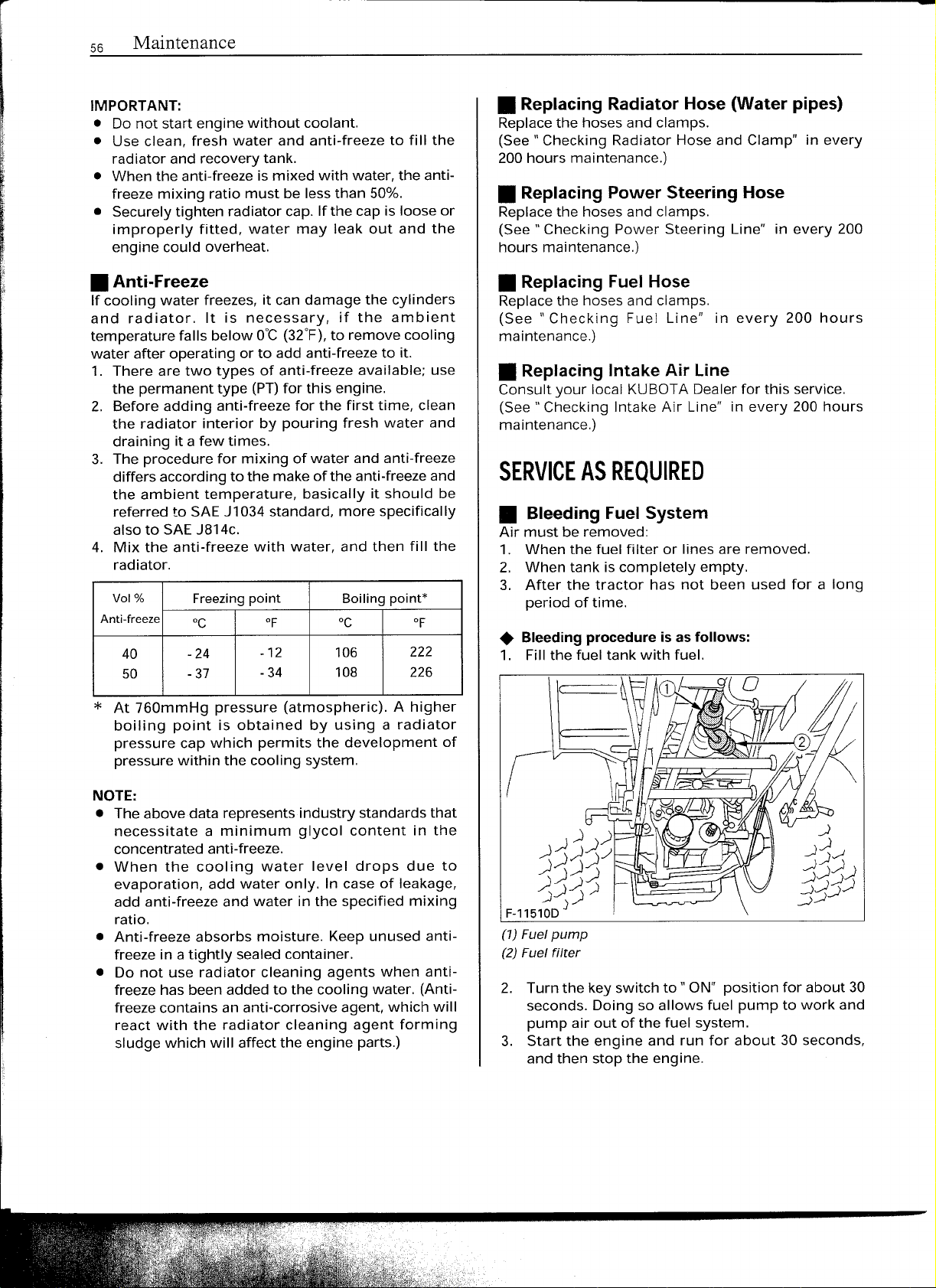
• Flush Cooling System and Changing
Coolant
CAUTION
A
1. Stop the engine, remove the key and let cool
2. To drain the coolant, open the radiator drain plug,
3. After all coolant is drained, close the drain plug.
4. Fill with clean water and cooling system cleaner.
5. FOllowdirections of the cleaner instruction.
6. After flushing, fill with clean water and anti-freeze
7. Fillwith coolant up to the "H" markon the recovery
8. Start and operate the engine for few minutes.
9. Stop the engine, remove the key and let cool.
10. Check coolant level of recovery tank and add
11. Properly dispose of usedcoolant.
(with recoverytank)
To avoid personal injury:
• Be sure to stop the engine and remove
the key before checking coolant level.
• Do not remove the radiator cap while
coolant is hot. When cool, slowly rotate
cap to the first stop and allow sufficient
time for excess pressure to escape
before removing cap completely.
down.
and remove radiator cap.The radiator cap must be
removed to completely drain the coolant.
until the coolant level isjust below the radiator cap.
Install the radiator cap securely.
tank.
coolant if necessary.
Coolantcapacity
BX 1800 BX 2200
2.9L(3.1 U.S.
qts.)
3.5L(3.7 U.S.
qts.)
• Checking Fuel Injection Nozzle
Injection Pressure
Consult your local KUBOTA Dealer for this service.
EVERY 3000 HOURS
• Checking Injection Pump
Consult your local KUBOTA Dealer for this service.
F-11514A
(1) Radiator cap
(2) Drain plug
Page 18
56
Maintenance
IMPORTANT:
• 00
not start engine without coolant.
• Use clean, fresh water and anti-freeze to fill the
radiator and recovery tank.
• When the anti-freeze is mixed with water, the anti-
freeze mixing ratio must be less than 50%.
• Securely tighten radiator cap. If the cap is loose or
improperly fitted, water may leak out and the
engine could overheat.
• Anti-Freeze
If cooling water freezes, it can damage the cylinders
and radiator. It is necessary, if the ambient
temperature falls below O°C(32°F),to remove cooling
water after operating or to add anti-freeze to it.
1. There are two types of anti-freeze available; use
the permanent type (PT)for this engine.
2. Before adding anti-freeze for the first time, clean
the radiator interior by pouring fresh water and
draining it afew times.
3. The procedure for mixing of water and anti-freeze
differs according to the make of the anti-freezeand
the ambient temperature, basically it should be
referred to SAEJ1034standard, more specifically
also to SAEJ814c.
4. Mix the anti-freeze with water, and then fill the
radiator.
Vol
%
Anti-freeze
40 -24
50 -37
Freezingpoint Boilingpoint*
°c
of
-12 106
-34
°c
222
108 226
of
• Replacing Radiator Hose (Water pipes)
Replacethe hoses and clamps.
(See" Checking Radiator Hose and Clamp" in every
200hours maintenance.)
• Replacing Power Steering Hose
Replacethe hosesand clamps.
(See" Checking Power Steering Line" in every 200
hours maintenance.)
• Replacing Fuel Hose
Replacethe hoses and clamps.
(See" Checking Fuel Line" in every 200 hours
maintenance.)
• Replacing Intake Air Line
Consult your local KUBOTADealerfor this service.
(See" Checking Intake Air Line" in every 200 hours
maintenance.)
SERVICE AS REQUIRED
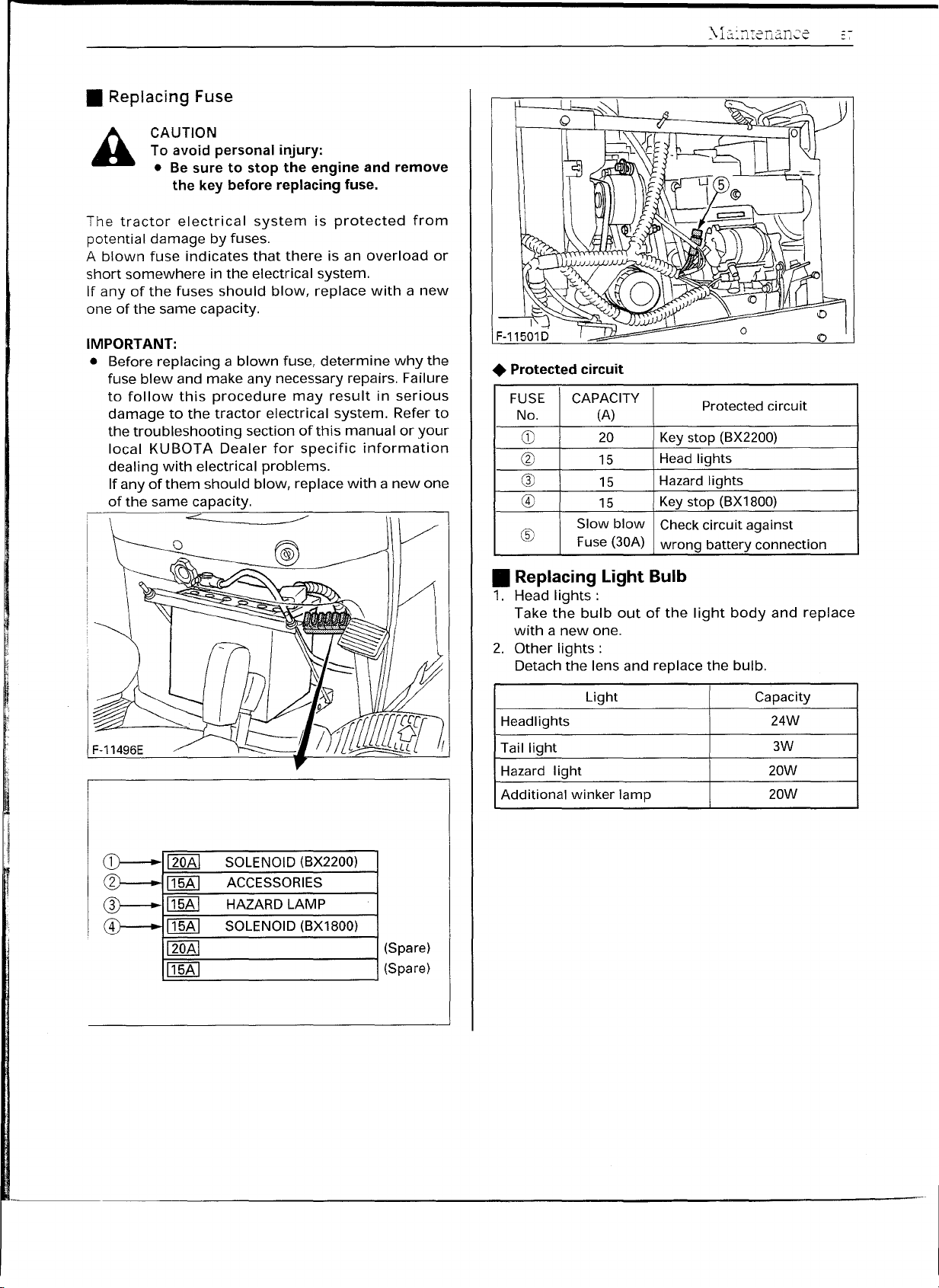
• Bleeding Fuel System
Air must be removed:
1. When the fuel filter or lines are removed.
2. When tank is completely empty.
3. After the tractor has not been used for a long
period of time.
• Bleeding procedure is as follows:
1. Fill the fuel tank with fuel.
*
At 760mmHg pressure (atmospheric). A higher
boiling point is obtained by using a radiator
pressure cap which permits the development of
pressure within the cooling system.
NOTE:
• Theabove data represents industry standards that
necessitate a minimum glycol content in the
concentrated anti-freeze.
• When the cooling water level drops due to
evaporation, add water only. In case of leakage,
add anti-freeze and water in the specified mixing
ratio.
• Anti-freeze absorbs moisture. Keep unused anti-
freeze in atightly sealed container.
• 00
not use radiator cleaning agents when anti-
freeze has been added to the cooling water. (Anti-
freezecontains an anti-corrosive agent, which will
react with the radiator cleaning agent forming
sludge which will affect the engine parts.)
.:
(1) Fuel pump
(2) Fuel filter
2. Turn the key switch to "ON" position for about 30
seconds. Doing so allows fuel pump to work and
pump air out of the fuel system.
3. Start the engine and run for about 30 seconds,
and then stop the engine.
Page 19
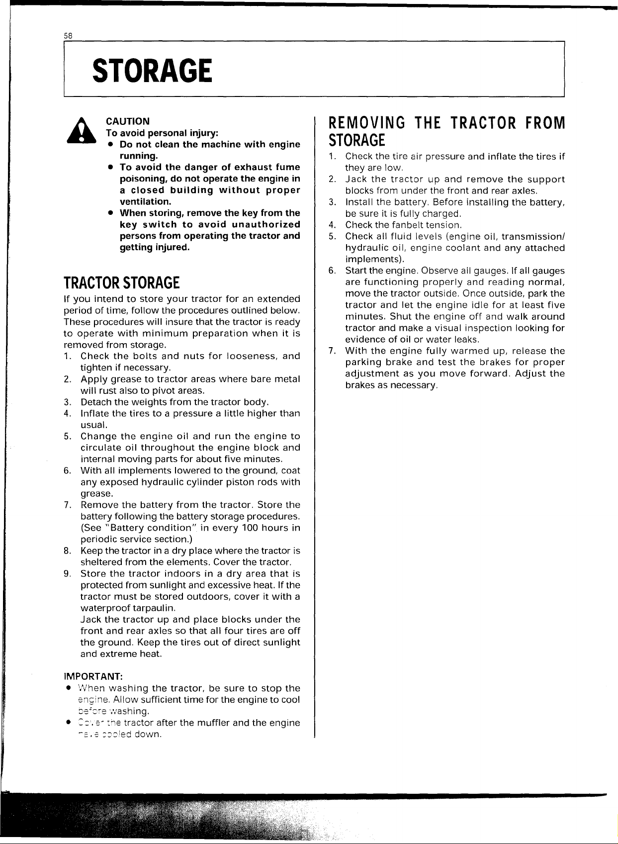
• Replacing Fuse
CAUTION
A
The tractor electrical system is protected from
potential damage by fuses.
A blown fuse indicates that there is an overload or
short somewhere in the electrical system.
If any of the fuses should blow, replace with a new
one of the same capacity.
IMPORTANT:
• Before replacing a blown fuse, determine why the
To avoid personal injury:
• Besure to stop the engine and remove
the key before replacing fuse.
fuse blew and make any necessary repairs. Failure
to follow this procedure may result in serious
damage to the tractor electrical system. Refer to
the troubleshooting section of this manual or your
local KUBOTA Dealer for specific information
dealing with electrical problems.
If any of them should blow, replace with a new one
of the same capacity.
~~~
\~:~
• Protected circuit
FUSE CAPACITY
No.
CD
@
G)
@
®
(A)
20
15
15
15
Slow blow
Fuse(30A)
Protectedcircuit
Keystop (BX2200)
Headlights
Hazardlights
Keystop (BX1800)
Checkcircuit against
wrong battery connection
• Replacing Light Bulb
1. Head lights:
Take the bulb out of the light body and replace
with a new one.
2. Other lights:
Detach the lens and replace the bulb.
F-11496E
CD---
2
®--
CD--
--
120AI
115AI
115AI
115AI
120AI
115AI
SOLENOID(BX2200)
ACCESSORIES
HAZARDLAMP
SOLENOID(BX1800)
(Spare)
(Spare)
Light Capacity
Headlights
Taillight
Hazard light 20W
Additional winker lamp
24W
3W
20W
Page 20
58
I
STORAGE
CAUTION
To avoid personal injury:
• Do not clean the machine with engine
running.
• To avoid the danger of exhaust fume
poisoning, do not operate the engine in
a
closed building without proper
ventilation.
• When storing, remove the key from the
key switch to avoid unauthorized
persons from operating the tractor and
getting injured.
TRACTOR STORAGE
If you intend to store your tractor for an extended
period of time, follow the procedures outlined below.
Theseprocedures will insure that the tractor is ready
to operate with minimum preparation when it is
removed from storage.
1. Check the bolts and nuts for looseness, and
tighten if necessary.
2. Apply grease to tractor areas where bare metal
will rust also to pivot areas.
3. Detachthe weights from the tractor body.
4. Inflate the tires to a pressure a little higher than
usual.
5. Change the engine oil and run the engine to
circulate oil throughout the engine block and
internal moving parts for about five minutes.
6. With all implements lowered to the ground, coat
any exposed hydraulic cylinder piston rods with
grease.
7. Remove the battery from the tractor. Store the
battery following the battery storage procedures.
(See "Battery condition" in every 100 hours in
periodic service section.)
8. Keepthe tractor in a dry placewhere the tractor is
sheltered from the elements. Coverthe tractor.
9. Store the tractor indoors in a dry area that is
protected from sunlight and excessiveheat. If the
tractor must be stored outdoors, cover it with a
waterproof tarpaulin.
Jack the tractor up and place blocks under the
front and rear axles so that all four tires are off
the ground. Keepthe tires out of direct sunlight
and extreme heat.
REMOVING THE TRACTOR FROM
STORAGE
1. Checkthe tire air pressure and inflate the tires if
they are low.
2. Jack the tractor up and remove the support
blocksfrom under the front and rear axles.
3. Install the battery. Before installing the battery,
be sure it is fully charged.
4. Checkthe fanbelt tension.
5. Check all fluid levels (engine oil, transmissioni
hydraulic oil, engine coolant and any attached
implements).
6. Start the engine.Observeall gauges. If all gauges
are functioning properly and reading normal,
move the tractor outside. Onceoutside, park the
tractor and let the engine idle for at least five
minutes. Shut the engine off and walk around
tractor and make a visual inspection looking for
evidence of oil or water leaks.
7. With the engine fully warmed up, release the
parking brake and test the brakes for proper
adjustment as you move forward. Adjust the
brakesas necessary.
IMPORTANT:
• ".Vhenwashing the tractor, be sure to stop the
encine. Allow sufficient time for the engine to cool
be:cre .•vashing.
• =
:'.e-
the tractor after the muffler and the engine
-::'.s
:::ied down.
Page 21

59
_TR_O_U_BL_E_SH_O_O_TI_NG
ENGINE TROUBLESHOOTING
If something is wrong with the engine, refer to the table below for the cause and its corrective measure.
Trouble
Engine is difficult to start or
won't start.
• No fuel flow.
• Air or water is in the fuel system.
.In
winter, oil viscosity increases,
and engine revolution is slow.
• Battery becomes weak and the
engine does not turn over quick
enough.
Cause Countermeasure
• Check the fuel tank and the fuel filter.
Replace filterifnecessary.
• Check to see if the fuel line coupler bolt
and nut are tight.
• Bleed the fuel system (See "Bleeding
Fuel system" in as required maintenance)
• Remove water from the system and
replace the fuel filter.
• Use oils of different viscosities,
depending on ambient temperatures.
• Use engine block heater. (Option)
• Clean battery cables and terminals.
• Charge the battery.
• In
cold weather, always remove the
battery from the engine, charge and
store it indoors. Install it on the tractor
only when the tractor is going to be
used.
I
Insufficient engine power.
Engine stops suddenly.
Black
Exhaust fumes are
colored.
Engine overheats.
If you have any questions, contact your local KUBOTA Dealer.
Blue
white
• Insufficient or dirty fuel.
• The air cleaner is clogged.
• Insufficient fuel.
• Fuel quality is poor.
• Too much oil.
• The air cleaner is clogged.
• The inside of exhaust muffler is
dumped with fuel.
• Injection nozzle trouble.
• Poor quality fuel.
• Engine overloaded.
• Low coolant level.
• Loose or defective fan belt.
• Dirty radiator core or grille
screens.
• Coolant flow route corroded. • Flush cooling system.
• Check the fuel system.
• Clean or replace the element.
• Refuel.
• Bleed the fuel system if necessary.
• Change the fuel and fuel filter.
• Check the proper amount of oil.
• Clean or replace the element.
• Heat the muffler by applying load to the
engine.
• Check the injection nozzle.
• Change the fuel and fuel filter.
• Shift to lower gear or reduce load.
• Fill cooling system to the correct level;
check radiator and hoses for loose
connections or leaks.
• Adjust or replace fan belt.
• Remove all trash.
--;;JII
Page 22

60
I
OPTIONS
Consult your local KUBOTA Dealer for further details.
• 18x 8.5-8 Bar Tire
·26 x 12.0-12 BarTire
• Grille guard
• Engine Block heater
For extremely cold weather starting
• RearWork Light
High visibility for night work
• Front end weight
For front ballast
• Rearwheel weight
• Sunshade for ROPS
Page 23

/
l
I
U.S.A. : KUBOTA TRACTOR CORPORATION
Western Division : 6665 E. Hardaway Rd., Stockton, CA 95215
Central Division : 14855 FAA Blvd., Fort Worth, TX 76155
Northern Division : 2626 Port Road, Columbus, OH 43217
Southeast Division : 1025 Northbrook Parkway, Suwanee, GA 30024
Canada : KUBOTA CANADA LTD.
Delta Distribution Center: 7979 82nd St, Delta B.C. V4G 1L7
Drummondville Distribution Center: 5705 Place Kubota, Drummondville, Quebec, J28 6B4
France KUBOTA EUROPE SA
Germany KUBOTA (DEUTSCHLAND) GmbH
U.K. KUBOTA (U.K.) LTD.
Australia KUBOTA TRACTOR AUSTRALIA PTY LTD.
Malaysia : SIME KUBOTA SDN. BHD.
Philippines: KUBOTA AGRO-INDUSTRIAL MACHINERY PHILIPPINES, INC.
Taiwan : SHIN TAIWAN AGRICULTURAL MACHINERY CO., LTD.
Brazil : KUBOTA BRASIL LTDA.
Indonesia : P.T. KUBOTA INDONESIA
Thailand : THE SIAM KUBOTA INDUSTRY CO., LTD.
Egypt : KUBOTA Corporation CAIRO LIAISON OFFICE
3401 Del Amo Blvd., Torrance, CA 90503, U.S.A.
Telephone: (310)370-3370
Telephone : (209)931-5051
Telephone : (817)571-0900
Telephone: (614)492-1100
Telephone : (770)995-8855
5900 14th Avenue, Markham, Ontario, L3S 4K4, Canada
Telephone: (905)294-7477
Telephone : (604)940-6061
Telephone : (819)478-7151
19-25, Rue Jules Vercruysse, Z.1.BP88, 95101 Argenteuil Cedex, France
Telephone: (33)1-3426-3434
Senefelder Str. 3-5 63110 Rodgau INieder-Roden, Germany
Telephone: (49)6106-873-0
Dormer Road, Thame, Oxfordshire, OX9 3UN, U.K.
Telephone : (44)1844-214500
100 Keilor Park Drive, Tullamarine, Victoria 3043 Australia
Telephone: (61)-3-9279-2000
Lot pt 11101 Kompleks Sime Darby, Jalan Kewajipan,
Subang Jaya, 47600 Petaling Jaya, Selangor Darul Ehsan. West Malaysia
Telephone: (60)3-736-1388
155 Panay Avenue, South Triangle Homes, 1103 Quezon City, Philippines
Telephone : (63)2-9201071
16, Fengping 2nd Rd, Taliao Shiang Kaohsiung 83107, Taiwan R.O.C.
Telephone: (886)7-702-2333
Rua Dona Maria Fldelis No.171, Diadema, Sao Paulo, Brazil
Telephone: (55)11-745-4744
JALAN. Setyabudi 279, Semarang, Indonesia
Telephone: (62)-24-472849
101/19-24
Telephone: (66)2-529-0363
Flat No.2,27th floor, Swiss Tower Building
3,Ibn Kasir Street, Cornish EL Nile, Giza, Egypt
Telephone: (20)2-338-3851
Navanakorn, Tambol Klongneung, Amphur Klcng.uang. Pathum:ani '2120. Thai,and
-'-,-'=-
~~ (U.SA)
Code~o-<25::' -
r
.!.
-
-,
O.i.7.12.6.L
-12'-5
Page 24

• Foot and Hand Controls
~------__(8)
Operation
15
l-------"""
I-------
<,
.---------~
--------------
~------~~~
::--1557A
~-----__(9)
---------(@
-------,QD
'----------(13
--=:;;.--------(Q~
ILLUSTRATED CONTENTS
(1)
Differential lock pedal 27
(2) Parking brake lock pedal 17,22,24,26
(3) 3-Point hitch lowering speed knob 32
(4) Cutting height control dial 33
(5) PTO select lever 28
(6) PTO clutch lever 17,29
(7) Seat belt 22
(8) Hand throttle lever 18,24
(9) Brake pedal 17,22,24,26
(10) Speed control pedal 17,24
(11)Hydraulic control lever 18,23
(12)Front wheel drive lever 23
(13)Rangegear shift lever (Hi-La) 17,23
(14)Operator's seat 21
iI$
a
,aSid
Page 25

Operation
16
I PR_E_-O_P_ER_A_TI_O_N _CH_E_C_K _
DAILY CHECK
To prevent trouble from occurring, it is important to
know the condition of the tractor well. Check it before
starting.
CAUTION
To avoid personal injury:
• Be sure to check and service the tractor
on a level surface with the engine shut
off and the parking brake "ON" and
implements lowered to the ground.
Check item
- Walk around inspection
- Check engine oil level
- Checktransmission oil level
- Checkcoolant level
- Clean grill and radiator screen
- Check air cleaner evacuator valve
(When used in a dusty place)
- Check brake pedal
- Check indicators, gauges and meter
- Check lights
- Checkwire harness
- Check seat belt and RaPS
- Refuel
(See "DAILY CHECK"in periodic service section.)
- Care of danger, warning and caution labels
(See "DANGER, WARNING AND CAUTION
LABELS" in safe operation section.)
- ~-~~---~-~-------- ----~--~----- ------~
Page 26

Operation
17
_O_PE_R_AT_IN_G_T_H_E_EN_G_IN_E
CAUTION
To avoid personal injury:
• Read "Safe Operation" in the front of
this manual.
• Read the danger, warning and caution
labels located on the tractor.
• To avoid the danger of exhaust fume
poisoning, do not operate the engine in
a closed building without proper
ventilation.
• Never start engine while standing on
ground. Start engine only from
operator's seat.
• Make it a rule to set all shift levers to the
"NEUTRAL" positions and to place PTO
lever in "OFF" position before starting
the engine.
IMPORTANT:
• Jo not usestarting fluid or ether.
• To protect the battery and the starter, make sure
.nat
the starter is not continuously turned for more
:..,an
30seconds.
2.
Place the PTO clutch lever in "OFF"
position.
3.
Place the speed control pedal in
"NEUTRAL" position.
Placethe range gearshift lever (Hi-Lo)in
"NEUTRAL" position.
I
STARTING
1.
Makesurethe parking brake is set.
- -: set the parking brake:
Jepress the brakepedal.
~ Latchthe brake pedal with the parking brake
- -: release the parking brake, depress the brake
:~:3
THE ENGINE
ockpedal.
again.
rA) "DEPRESS"
B) PUSH FORWARD
'NHILE DEPRESSING ®
f!1
(1) PTO clutch lever
(2) Speed control pedal
(3) Range gear shift lever (Hi-La)
NOTE:
• The speed control pedal automatically return to
neutral when the operator's foot is released from
the pedal.
"ON"
Jltl
"OFF"
iJt
"Hi"
(N) "NEUTRAL
POSfTfON"
--- "La"
Page 27

Operation
20
JUMP STARTING
CAUTION .
To avoid personal injury:
A
Whenjump starting engine, follow the instructions
below to safely start the engine.
1. Bring helper vehicle with a battery of the same
2. Engagethe parking brakes of both vehicles and
3. Puton safety goggles and rubber gloves.
4. Ensure the vent caps are securely in place. (if
5. Cover vent holes with damp rags. Do not allow
6. Attach the red clamp to the positive (red,
7. Clampthe other cable to the negative (black,eor
8. Clampthe other end to the engine block or frame
9. Startthe helpervehicle and let its engine run for a
10. Disconnectthejumper cables in the exact reverse
11. Removeand discard the damp rags.
• Battery gases can explode. Keep
cigarettes, sparks, and flames away
from battery.
• If tractor battery is frozen, do not jump
start engine.
• Do not connect other end of negative
jumper cable to negativeeterminal of
tractor battery.
voltage as disabled tractor within easy cable
reach. "THE VEHICLESMUST NOTTOUCH".
put the shift levers in neutral. Shut the engines
off.
equipped)
the rag to touch the battery terminals.
pos.) terminal of the dead battery and clamp the
other endof the same cableto the positive (red,
or pos.)terminal of the helper battery.
neg.)terminal of the helper battery.
of the disabled tractor asfar from the deadbattery
as possible.
few moments. Start the disabled tractor.
order of attachment. (Steps 8, 7 and 6).
ffi
e
Connect cables in numerical order.
Disconnect in reverse order after use.
e
ground
or
ffi
F-11511A
(1) Dead battery
(2) Lay a damp rag over the vent caps
(3)Jumper cables
(4) Helper battery
IMPORTANT:
• This machine has a 12volt negative
starting system.
• Useonly same voltage forjump starting.
• Use of a higher voltage source on tractors
electrical system could result in severe damage to
tractors electrical system.
Use only matching voltage source when "Jump
starting" a low or dead battery condition.
j
UJ ..
L
Page 28

Operation
21
_O_PE_R_AT_IN_G_T_H_E _TR_A_C_TO_R
OPERATING NEW TRACTOR
-: ... a new tractor is handled and maintained
:~:ermines the life of the tractor .
.:,new tractor just off the factory production line has
oeen, of course, tested, but the various parts are not
accustomed to each other, so care should be taken to
coer ate the tractor for the first
5:~ed and avoid excessive work or operation until
:-~ .arlous parts become "broken-in.". The manner
- ,',- ch the tractor is handled during the "breaking-
oeriod greatly affects the life of your tractor.
--~-efore, to obtain the maximum performance and
:-s
ongest life of the tractor, it is very important to
: -::erly break-in your tractor. In handling a new
:-s::or, the following precautions should be
::5~:-ved.
• Do not Operate the Tractor at Full Speed
for the First 50 Hours.
• Do
• ln winter, operate the tractor after fully warming
• Jo not run the engine at speeds faster than
• On rough roads, slow down to suitable speeds.
-re above precautions are not limited only to new
:-s:tors, but to all tractors. But it should be especially
::"erved in the case of new tractors.
not start quickly nor apply the brakes
suddenly,
..:p
the engine.
necessary.
Jo not operate the tractor at fast speed.
• Changing Lubricating Oil for New
Tractors
--~ lubricating oil is especially important in the case
:; a new tractor. The various parts are not "broken-
- and are not accustomed to each other; small
+-etal
grit may develop during the operation of the
:-s::tor.: and this may wear out or damage the parts.
--erefore, care should be taken to change the
_::~iGating oil a little earlier than would ordinarily be
-=-:.Jired.
=:-
"urther details of change interval hours, see
I.'.~
\TENANCE" section.
50
hours at a slower
STARTING
1.
Adjusting the Operator's Position.
• Operator's Seat
CAUTION
To avoid personal injury:
• Make sure that the seat is completely
securedafter each adjustment.
• Do not allow any person other than the
driver to ride on the tractor.
• Travel adjustment
Pullout the position adjust lever and slide the seat
backward or forward, as required. The seat will lock in
position when the lever is released .
lei
./j,J
\J\/
~
F-11480B
(1) Seat
(2) Position acljust
IMPORTANT
• After adjusting the operator's seat, be sure to
check that the seat is properly locked.
lever
(A) "PULL OUT"
I
----~.---
Page 29

Operation
22
• Seat Belt
CAUTION
A
Adjust the seat belt for proper fit and connect to the
buckle.The seat belt is auto-locking retractable type.
To avoid personal injury:
• Always use the seat belt when the ROPS
is installed.
Do not use the seat belt if the tractor is
not equipped with ROPS.
F-11482A
(1) Hazard light switch
(2) Head light switch
(3) Turn signal light switch
(A) "ON"
(B) "OFF"
(C) "RIGHT TURN"
(0) "LEFT TURN"
3. Checking the Brake Pedal.
F-11478B
(1) Seat belt
2.
Selecting Light Switch Positions.
• Head Light Switch
(A) Head lights ON.
(B) Headlights OFF.
• Hazard Light Switch
When hazard light switch is pushed down forward,
the hazard lights flash along with the indicator on the
instrument panel. Pushthe switch down backward to
turn off the light.
(A) Hazard lights ON.
(B) Hazardlights OFF.
• Turn Signal Light Switch
To indicate a right turn, push down forward.
To indicate a left turn, push down backward.
When the left or right turn signal is activated in
combination with the hazard lights, the indicated
turning light will flash and the other will stay on.
• Brake Pedal
Make sure to latch the brake pedal with the parking
brake lock pedal.
CAUTION
A
To avoid personal injury:
• An accident may occur if the tractor is
suddenly braked, such as by heavy
towed loads shifting forward or loss of
control.
• The braking characteristics are different
between two and four wheel drive. Be
aware of the difference and use
carefully.
• When driving on icy, wet or loose
surfaces, make sure the tractor is
correctly ballasted to avoid skidding and
loss of steering control. Operate at
reduced speed.
NOTE:
• Be sure to return switch to center position after
turning.
::.----=:>
F-13507A
(7) Parking brake lock pedal
(2) Brake pedal
Page 30

-
4.
Raise the Implement. (see "HYDRAULIC
UNIT" section)
Move the hydraulic control lever rearward.
I
F-'14~
7/
Hydraulic control lever
Hydrauliccontrolleverisautomaticallyreturnedto neutral
positionwhentheimplementisraisedattop position.
5.
Selecting the Travel Speed.
(A) "UP"
Operation
• Front Wheel Drive Lever
CAUTION
To avoid personal injury:
• Do not engage the front wheel drive
when traveling at road speed.
• When driving on icy,wet or loosesurfaces,
make sure the tractor iscorrectly ballasted
to avoid skidding and loss of steering
control. Operate at reduced speed and
engagefront wheel drive.
• An accident may occur if the tractor is
suddenly braked, such as by heavy towed
loads shifting forward or lossof control.
• The braking characteristics are different
between two and four wheel drive. Be
aware of the difference and use carefully.
Use the lever to engage the front wheels with the
tractor stopped. Shift the lever to "ON" to engagethe
front wheel drive.
23
• Range Gear Shift Lever (Hi-La)
The range gear shift can only be shifted when tractor
is completely stopped.
IMPORTANT:
Do not force the range gear shift lever.
• If it is difficult to shift the range shift lever into
neutral position;
1. Depressthe brakepedalfirmly for severalseconds.
2. Without reducing the brake pedal force, shift
the range shift lever.
• If it is difficult to shift the range shift lever into "L"
or "H" from neutral position;
1. Slightly depress the speed control pedal to
rotate the gears inside of transmission.
2. Releasethespeedcontrolpedalto neutralposition.
~ Shift the range shift lever.
• i..J
avoid damage of transmission, stop tractor
befcre shifting between ranges.
":tI
(1) Front wheel drive lever
IMPORTANT:
• To avoid damage of transmission, when front
wheel drive lever is not smoothly shifted, slightly
step forward or rearward on speedcontrol pedal.
• Tires will wear quickly if front wheel drive is
engaged on paved roads.
• Front wheel drive is effective for the following
jobs:
1. When greater pulling force is needed, such as
working in a wet field, when pulling a trailer, or
when working with a front-end loader.
2. When working in sandy soil.
3. When working on a hard soil where a rotary tiller
might push the tractor forward.
4. Additional braking at reduced speeds.
~ "ON"
Jl'.t
"OFF"
(1) Range gear shift lever
(Hi-La)
if'
"HIGH"
(N) "NEUTRAL POSITION"
•••. "LOW"
Page 31

24
;;
Operation
6. Accelerate the Engine.
• Hand Throttle Lever
Pulling the throttle lever backincreases engine speed,
and pushing it forward decreasesengine speed.
F-13515A
(1) Hand Throttle lever
7.
Unlock the Parking Brake .
~ "INCREASE"
--- "DECREASE"
8. Depress the Speed Control Pedal.
• Speed Control Pedal
WARNING
To avoid personal injury:
• Do not operate if tractor moves on
ground with foot off Speed
Pedal.
Forward Pedal
Depress the forward pedal with the toe of your - ~_.
foot to move forward.
Reverse Pedal
Depressthe reverse pedal with the heel of your - ~-
foot to move backward.
@
@
Ie.:;,
Cont·:
• Parking Brake Pedal
To releasethe parking brake, depress the brake pedal
again.
~
F-11486B ~
(1) Brake pedal
~
0
(A) "FORWARD"
(B) "REVERSE"
IMPORTANT:
• To prevent serious damage to the H5T, c: --
adjust the stopper bolts.
Page 32

Operation
25
STOPPING
• Stopping
. S
::;,'i
the engine down.
- S:ep
on the brakepedal.
":''ier the tractor has stopped, disengage the PTO,
:::'/ier the implement to the ground, shift the
::-ansmissionto neutral and set the parking brake.
CHECK DURING DRIVING
• Immediately Stop the Engine if:
• The engine suddenly slows down or accelerates,
• Unusual noises suddenly are heard,
• Exhaustfumes suddenly become very dark,
",'''1iledriving, make the following checks to see that
- ' the parts are functioning normally.
\
• Easy Checker
If the warning lamps in the EasyChecker" come on
during operation, immediately stop the engine, and
find the cause as shown below,
Never operate the tractor while Easy
is on,
~Engine oil pressure
If the oil pressure in the engine goes below the
prescribed level, the warning lamp in the Easy
Checker"
If this should happen during operation, and it
does not go off when the engine is acceleratedto
more than
(See"CheckingEngineOil Level" in daily check in
periodic service section.)
t::3
Electrical charge
If the alternator is not charging the battery, the
warning lamp in the Easy
on.
If this should happen during operation, checkthe
electrical charging system or consult your local
KUBOTADealer.
NOTE:
• Forchecking and servicing of your tractor, consult
your local KUBOTADealer for instructions .
™
will come on.
1000
rpm, checklevel of engine oil.
Checker"
Checker"
will come
lamp
:=asychecker"
- ~_'efgauge
- :aofant temperature gauge
• Fuel Gauge
When the key switch is on, the fuel gauge indicates
the fuel level.
Be careful not to empty the fuel tank. Otherwise air
may enter the fuel system.
Should this happen, the system should be bled (See
"Bleeding Fuel System" in as required in Periodic
Service Section)
(7)
Fuel gauge
(A) "EMPTY"
(8) "FULL"
Page 33

26
Operation
• Coolant Temperature Gauge
CAUTION
To avoid personal injury:
• Donot remove radiator capuntil coolant
temperature is well below its boiling
point. Then loosen cap slightly to the
stop to relieve any pressure before
removing capcompletely.
1. With the key switch at "ON", this gauge indicates
the temperature of the coolant.
2. If the indicator reaches the "Hot" position (red
zone), engine coolant is overheated. Check the
tractor by referring to "Troubleshooting" section.
PARKING
• Parking
CAUTION
To avoid personal injury:
• Always set the parking brake, stop the
engine and remove the key before
leaving the tractor seat.
1. When parking, be sure to set the parking brake.
To set the parking brake;
1) Depressthe brake pedal.
2) Latch the brake pedal with the parking brake
lock pedal.
(1) Coolant temperature gauge
• Hourmeter
The hourmeter indicates in five digits the hours the
tractor has been used;the last digit indicates
an hour.
1/10
~
F-13507A
(1) Parking brake lock pedal
(2) Brake pedal
of
2. Beforegetting off the tractor, disengagethe PTO,
lower all implements to the ground, place all
control levers in their neutral positions, set the
parking brake, stop the engine and remove the
key.
3. If it is necessaryto park on an incline, be sure to
chock the wheels to prevent accidental rolling of
the machine.
J
Page 34

Operation
27
OPERATING TECHNIQUES
• Differential Lock
h
WARNING
~ To avoid personal injury due to loss of
steering control:
• Do not operate the tractor at high speed
with differential lock engaged.
• Do not attempt to turn with the differential
lockengaged.
• Be sure to release the differential lock
before making a turn in field conditions.
If one of the rear wheels should slip, step on the
differential lock pedal. Both wheels will then turn
tcqether. reducing slippage.
Differential lock is maintained only while the pedal is
cepressed.
!1)
Differential lock pedal (A) Press to "ENGAGE"
(B) Release to "DISENGAGE"
IMPORTANT:
• When using the differential lock, always slow the
engine down.
• To prevent damage to power train, do not engage
differential lock when one wheel is spinning and
the other is completely stopped.
• if
the differential lock cannot be released in the
above manner, alternately step speed control
cecal forward and backward slightly.
Be sure SMV emblem and warning lamps are clean
and visible. If towed or rear-mounted equipment
obstructs these safety devices, install SMV emblem
and warning lamps on equipment.
Consult your local KUBOTADealerfor further details.
:J
\
F-11491A
(1)
SMVemblem
(2)Bracket
.)
• Operating on a Slopes and Rough Terrain
h
•• To avoid personal injury:
1. Slow down for slopes, rough ground, and sharp
2. Before descending a slope, shift to a gear low
CAUTION
• Always back up when going up a steep
slope. Driving forward could cause the
tractor to tip over backward. Stay off
hills and slopes too steep for safe
operation.
• Avoid changing gears when climbing or
descending a slope.
• If operating on a slope, never disengage
shift levers to neutral. Doing so could
cause loss of control.
• Do not drive the tractor closeto the edges
of ditches or banks which may collapse
under the weight of the tractor. Especially
when the ground is loose or wet.
turns, especially when transporting heavy, rear
mounted equipment.
enough to control speed without using brakes.
• Operating the Tractor on a Road
CAUTION
A
To avoid personal injury:
• When traveling on road with 3-point
hitch mounted implement
sure to have sufficient front weight on
the tractor to maintain steering ability.
attached,
be
• Directions for Use of Power Steering
1. Power steering is activated only while the engine
is running. While the engine is stopped, the tractor
functions in the same manner as tractors without
power steering.
2. When the steering wheel is turned all the way to
the stop, the relief valve is activated. Do not hold
the steering wheel in this position for a long period
of time.
3. Avoid turning the steering wheel while the tractor
is stopped, or tires may wear out sooner.
4. The power steering mechanism makes the
steering easier. Becareful when driving on a road
at high speeds.
Page 35

Operation
28
PTO
PTO OPERATION
WARNING
To avoid personal injury:
• Before operation, be sure to select the
correct PTO lever (mid, mid/rear, rear).
CAUTION
To avoid personal injury:
• Disengage PTO, stop engine, and allow
all rotating components to come to a
complete stop before connecting,
disconnecting, adjusting, or cleaning
any PTO driven equipment.
• PTOSelect lever
The tractor has a 540 rpm rear PTO speed and a 2500
rpm mid-PTO speed.
@
® ©
__ TCIT.••.TClT·•• _
• Mid-PTO . . __
To use Mid-PTO, shift the PTOselect lever to
position and the PTOclutch lever to "ON" posit
• Mid-Rear PTO _
To use mid and rear PTO at the same time, sh': --"
PTOselect lever to mid-rear PTOposition and the ::-
clutch lever to "ON" position.
• Rear PTO . __
To use rear PTO,shift the PTOselect lever to rea- - -
position and the PTO clutch lever to "ON" posit.c '
IMPORTANT:
• To avoid shock loads to the PTO, reduce er ;
throttle from full to half speed by pushing u; :-
engine throttle when engaging the PTO, the~
engage the engine to full. _
• To avoid damage of transmission, when - _
select lever is not smoothly shifted, slightly _
PTO clutch lever.
• Mid-PTO
The Mid-PTO is available for KUBOTA appr:
implements.
M:c--
=-
-7
'7-
=
(1) PTO select lever
(A) Mid-PTO position
(B) Mid-Rear-PTO position
(C)Rear-PTO position
Page 36

Operation
29
)
• PTO Clutch Lever
• --"2
.::. Shiftthe leverto "ON" to engagethe PTOclutch.Shift
~TOclutchleverengagesor disengagesthe PTO
::l...itchwhich givesthe PTOindependentcontrol.
theleverto "OFF"to disengagethe PTOclutch.
=
F-11484A
i1)
PTO clutch lever
IMPORTANT:
• To avoid shock loads to the PTO, reduce engine
throttle from full to half speed by pushing up on
engine throttle when engaging the PTO, then re-
engage the engine to full.
• To avoid damage to PTO clutch and implement,
shift the PTO clutch lever slowly, when engaging
the PTOclutch. Do not keep the PTOclutch lever
halfway.
NOTE:
• Tractor engine will not start if the PTOclutch lever
is in the engaged "ON" position .
f!1
"ON" "ENGAGE"
r.,
"OFF" "DISENGAGE"
• PTO Drive Shaft
4
F-11607A
(1) Inner and outer sliding profile tubes
(2)Journal cross assy
(3) Fitting yoke
(4) Safety guard (In, Out)
(5) Chain
1. When using a PTO drive shaft, should read the
operator's manuals of implement manufacturers
before operating the implement.
PTO drive shafts are designed for specific
machines and power requirement.
2. To adjust the length of PTOdrive shaft, refer the
following instructions.
q
To adjust the length, hold the half shafts next
to each other in the shortest working position
and mark them.
w
Shorten inner and outer guard tubes equally.
e Shorten inner and outer sliding profiles tube
by the same length asthe guard tubes.
r
Round off all sharp edges and remove burrs.
Greasesliding profiles.
i
• PTO Shaft Cover and Shaft Cap
Keepthe PTOshaft cover in placeat all times. Replace
I'
the PTOshaft cap when the PTOis not in use. Before
connecting or disconnecting a drive shaft to PTO
shaft, be sure engine is "OFF" and raise up the PTO
shaft cover.
Afterward be sure to return the PTOshaft cover to the
"NORMAL POSITION".
=-'14938
• PTO
:z
PTO
shaft cover
shaft cap
(A)"NORMAL POSITION"
(B)"RAISED POSITION"
3. Ensure that the PTO drive shaft is securely
connected at both ends before operating.
.~.-.--
~
..
--.--
----.----~-----
----~ -
Page 37

30
Operation
THREE·POINT HITCH
&
2}-----4~==n
~
5
DRAWBAR
...---i~-----cv
')
).J
\ .J
\
\
:
])
®
F-12362A
Use holder plate to hold lower link higher while
mowing with mid-mount mower only over uneven
terrain.
F-12363A
(1) Holder plate
(1) Top link
(2) Holder plate
(3) Lifting rod (Left)
(4) Check chains
(5)
Turnbuckle
(6) Lower link
(7)Top link holder
(8)Lifting rod (Right)
(9) Hitch
Page 38

Operation 31
J.IOIir
HITCH
• ~ing and detaching implements
CAUTION
To avoid personal injury:
• Besure to stop the engine and remove
the key.
• Do not stand between tractor and
implement unless parking brake is
applied.
• Before attaching or detaching
implement, locate the tractor and
implement on a firm, flat and level
surface.
• Whenever an implement or other
attachment is connected to the tractor
3-point hitch, check full range of
operation for interference, binding or
PTOseparation.
• lifting Rod(Right)
_?,'S
s 3-point mounted implement from side to side
:' ..,-- ng the adjusting turnbuckle to shorten or
2-,~-sn
:,,-:-s
!":s'-
--'
~:,,~,
the adjustable lifting rod with the implement
ground.
aqiustment. tighten the locknut securely.
~--'"
• CheckChains
Adjust the turnbuckle to control horizontal sway of
the implement.
After adjustment, retighten the lock nut.
HITCH
WARNING
A
To avoid personal injury:
• Never pull from the top link, the rear
axle or any point above the hitch. Doing
so could cause the tractor to tip over
rearward causing personal injury or
death.
e, •..
.!::-2A
- .:~ ~sting turnbuckle
CAUTION
A
To avoid personal injury from separation:
• Do not extend lift rod beyond the edge
of flat face on the threaded rod.
• TopLink
. ~::tust the angle of the implement to the desired
:,:sition by shortening or lengthening the top link.
- --2
proper length of the top link varies according
:: ':J'"'etype of implement being used.
F-11493C
(1)Hitch
Page 39

Operation
32
HYDRAULIC UNIT
I
'--------
3·POINT HITCH CONTROL SYSTEM
• Hydraulic Control
Operating the hydraulic control lever actuates the
hydraulic lift arm, which controls the elevation of 3-
point hitch mounted implement.
To lower implement, move the hydraulic control lever
forward; to raise it, move the hydraulic control lever
rearward.
Hydraulic control lever is automatically returned to
neutral position when the implement is raised at top
position or down at lowest position.
• Implement Lowering Limit
The implement lowering limit can be changed by
shifting the locker.
(3) Nuts
• Lower Limit
The lower limit can be changed by adjusting the
position of locker. Shifting the locker backward
raises the lower limit and shifting it forward
lowers the lower limit.
(1) Hydraulic control lever
(A) "~OWN"
(N) "NEUTRAL"
(B) "UP"
IMPORTANT:
• If the 3-point hitch can not be raised by setting the
hydraulic control lever to the UP position after
long term storage or when changing the
transmission oil, follow these air bleeding
procedures.
1. Stop the engine.
2. Set the hydraulic control lever to the down
position and start the engine.
3. Operatethe engine at low idlespeedfor at least
30secondsto bleedair from the system.
• Do not operate until the engine is warmed up. If
operation is attempted when the engine is still
cold, the hydraulic system may bedamaged.
• If noises are heard when implement is lifting after
the hydraulic control lever has been activated, the
hydraulic mechanism is not adjusted properly.
Unlesscorrected the unit will bedamaged.
Contactyour KUBOTADealerfor adjustment.
• 3-point Hitch Lowering Speed
CAUTION
To avoid personal injury:
• Fast lowering speed may causedamage
or injury. Lowering speed of implement
should be adjusted to two or more
seconds.
The lowering speed of the 3-point hitch can be
controlled by adjusting the 3-point lowering speed
knob.
\!
/\,1
1../\/
~
F-11480A
(1) 3-Point lowering speed knob
(A) "FAST"
(B) "SLOW"
(C) "LOCK"
Page 40

Operation
33
Alj!lllUARY HYDRAULICS
:::1'" ::-~rsctor hydraulic outlet is provided.
• Hydraulic Outlet
....,,'0"=_ :;
:ce'-:::::-j
:::I,·,i3.=e
:::,:;"r-e-
---
outlet is useful when adding hydraulically
equipment such as front end loader, front
=::
+iptement
~=-cve the blockcover.
':':-...=:h
• _38TA
~=_,8
the block outlet cover. (option)
--e
block outlet cover is standard part for
the implement inlet, outlet and return pipes
-:.58S)
/
is attached
Implement)
asshown in the illustration.
IMPORTANT:
• For hydraulic outlet, be sure to use the control
valve of the "Power beyond type" (with relief
valve) and third line return to tank for the
operation of hydraulic block.
MOWER LIFT LINKAGE SYSTEM
• Cutting Height Control Dial
').-1
/lei
\J\,J
~
F-11480D
(1) Cutting height control dial
(2)
Hydraulic control lever
:5xk
cover
.: :5
:xk
outlet cover (option)
:: ::_t.iet
- ....;~.dJau/iccontrol valve
(A)
Return port
(B)
To implement (outlet)
Max. flow
17
i/min
(4.5 U.S.gals./min)
No relief valve in
the hydraulic block.
(C)From implement
(inlet)
(1)
Mower rear link
When mounting the Mid-mount mower, turn the
cutting height control dial to the desired height.
For further details, refer to the operator's manual of
ROTARY MOWER RCK60B-22BX, RCKS4-22BX.
IMPORTANT:
When operating the tractor without Mid-mount
mower:
1. Move the hydraulic lever rearward to raise the
mower rear links to the highest position.
2. Set the cutting height control dial to "TOP"
position.
If not do so, damage of the mower rear link canresult.
Page 41

• Hydraulic Control Unit Use Reference Chart
In
order to handle the hydraulics properly, the operator must be familiar with the following.
Though this information may not be applicable to all types of implements and soil conditions, it is useful for general conditions.
"
Implement
••.•.......J.
[OJ
F-2016A
F-11483E
Soil condition
(1) Hydraulic control lever
Gauge wheelI(1) Check chains
Remarks
w
.j:>.
o
'"d
g
~
•.....
o
i=i
Moldboard plow
Disc plow
Harrower (spike,
springtooth, disc type
Sub-soiler .
Weeder, ridger .
Earthmove, digger
scraper, manure fork
rear carrier. ....
Mower (mid-and rear-
mount type) Hayrake.
tedder .
Light soil
Medium soil
heavy soil
Hydraulic control
YES/NO
YES
YES/NO
Loose
Tighten
Adjust t he check cha ns so
that the implement can move
5 to 6 cm (2.0 to 2.4 in.)
laterally.
Check chains should be tight
enough to prevent excessive
implement movement when
implement is in raised
position.
For implements with gauge
wheels, lower the position
control lever all way.
Page 42

Operation
35
TIRES, WHEELS AND BALLAST
------
llRES
WARNING
To avoid personal injury:
• Donot attempt to mount a tire on a rim.
This should be done by a qualified
person with the proper equipment.
• Always maintain the correct tire
pressure.
Do not inflate tires above the
recommended pressure shown in the
operator's manual.
MPORTANT:
• :: not use tires other than those approved by
-JBOTA.
• :. hen you intend to mount different size of tires
+orn equipped ones, consult your dealer about
+ont
drive gear ratio for details.
Excessivewear of tires may occur due to improper
gear ratio.
• Inflation Pressure
Though the tire pressure is factory-set to the
prescribed level, it naturally drops slowly in the
course of time. Thus, check it everyday and inflate as
necessary.
Tire sizes
Rear
Front
NOTE:
• Maintain the maximum pressure in front tires, if
26x12.00-12Turf 140kPa(1.4kgflcm2,20 psi)
26x12.00-12Bar
18x8.50-8Turf
18x8.50-8Bar
using a front loader or when equipped with a full
load of front weights.
Inflation Pressure
140kPa(1.4
150kPa(1.5kgf/cm2,22psi)
150kPa(1.5kgf/cm2,22psi)
kgf/cm2,20
psi)
I
WHEEL TREAD
CAUTION
To avoid personal injury:
• Support tractor securely on stands before removing a wheel.
• Never operate tractor with a loose rim, wheel, or axle.
• Front Wheels
::'ont tread can not be adjusted.
IMPORTANT:
• Do not turn front discs to obtain wider tread.
Models
Tire
18x 8.50-8Turf 18x 8.50- 8 Bar
r+--~\
i
N:
Tread
V,
_~l~l __
BX1800• BX2200
-~
:
I
'\
-~
910mm
35.8
in.
~'r
I
"]v
i'\
~,
\
!
I
-~--
910mm
35.8
I
in.
F-8440
Page 43

_--------------w------------------------------------------------
Operation
36
• Rear Wheels
Reartread width can not be adjusted.
IMPORTANT:
• Do not turn rear discs to obtain wider tread.
Models
Tire
Tread
IMPORTANT:
• Always attach tires as shown in the drawings.
• If not attached as illustrated, transmission parts may be damaged.
• When re-fitting or adjusting a wheel, tighten the bolts to the following torques then recheck after driving the
tractor 200m (200yards) and thereafter daily check service.
NOTE:
• Use the tapered bolts for wheels with beveled or tapered holes.
26x12.00-12 Turf
I
I 820 mm
32.2 in.
1/
BX1800• BX2200
26x 12.00-12 Bar
820mm
32.2 in.
II
F-3608il!1:A
(1)
Bolt
JA
Front
749.2
to 779.0 Nrn
75.2to78.3
(
110to132
Rear
108.5to130.2
11.1to13.3
(
80
to 96
II
kgf.m)
tt-lbs
Nrn
kgf.m)
tt-lbs
Page 44

Operation 37
•..... ,'....' ·....111"11"1 ,I,
:~.
e
'T
CAUTION
To avoid personal injury:
• Additional ballast will be needed for
transporting heavy implements. When
the implement is raised, drive slowly
over rough ground, regardless of how
much ballast is used.
• Do not fill the front wheel with liquid to
maintain steering control.
• Front Ballast
~.:I:.',=ghts if needed for stability and improve
"'"lEE,:
-,,,,. -:.= ":
;':?-,:.
• Front EndWeights (option)
--'e
~~ <Jur implement operator's manual for required
- _--:Jer
:::e=
~<QTE:
:Jlling and heavy rear mounted implements
=-:::
• Besides the weight, a front weight bracket and
ift front wheels. Add enough ballast to
steering control and prevent tip over.
eweiqht when no longer needed.
=-":ntend weights can be attached to the bumper.
of weights or consult your local KUBOTA
=~
to use.
., ountlnq bolt kit(s) are required for mounting the
.'.eight.
• Rear Ballast
Add weight to rear wheels if needed to improve
traction or for stability. The amount of rear ballast
should be matched tojob and the ballast should be
removed when it is not needed.
The weight should be added to the tractor in the form
of liquid ballast.
• Liquid Ballast in RearTires
Water and calcium chloride solution provides safe
economical ballast. Used properly, it will not damage
tires, tubes or rims. The addition of calcium chloride
is recommended to prevent the water from freezing.
Use of this method of weighting the wheels has the
full approval of the tire companies. See your tire
dealer for this service.
Liquid weight per tire (75 Percent filled)
Tire sizes
Slush free at -10°C (14°F)
Solid at -30°C (-22°F)
[Approx. 1kg (2 Ibs.)
CaCI2per 4 L (1gal) of water]
Slush free at -24°C (-11°F)
Solid at -47°C (-52°F)
[Approx. 1.5kg (3.5Ibs.)
CaCI2per 4 L (1gal) of water]
Slush free at -47°C (-52°F)
Solid at -52°C (-62°F)
[Approx. 2.25kg (5 Ibs.)
CaCI2per 4 L (1gal) of water]
IMPORTANT:
• Do not fill tires with water or solution more than
75%of full capacity (tothe level of valve stem at 12
o'clock position).
26x12.00-12
45kg
(99
Ibs.)
50kg
(110Ibs.)
56kg
(123Ibs.)
=-'1476A
='ont end weights
~ Front
iMPORTANT:
• Jo not overload tires.
• Add no more weight than indicated in chart.
weight bracket (option)
Maximum weight 125 kg (275Ibs.)
®
F-7749A
(1)Air
(2) Water
• To avoid damage of transmission, do not use rear
wheel weights and liquid ballast at the sametime.
(A) Correct,'
Air compresses like a cushion
(B)Incorrect,' 100% Full
Water can not be compressed
75%
Full
Page 45

Maintenance
38
I_M_AI_N_TE_N_AN_C_E _
SERVICE INTERVALS
=----------::d
No.
Items
1
Engine oil
2
Engine oil filter
Transmission oil filter
3
Transmission fluid
4
5
Transmission strainer
Front axle case oil
6
Front axle pivot
7
8
Engine start system Check
Greasing
9
10 Wheel bolt torque
Battery condition Check
11
12 Air cleaner element
13 Fuel filter
Fan belt
14
HST neutral spring
15
Brake
16
Radiator hose and
17
clamp
Power steering oil line
18
Fuel line
19
Intake air line
20
21
Toe-in
22 Engine valve clearance Adjust
Fuel injection nozzle
23
injection pressre
24
Injection pump Check
25
Cooling system
26
Coolant
27 Fuel system
28 Fuse
Light bulb
29
Change
Replace
Replace
Change
Clean
Change
Adjust
Check
Clean
Replace
Check
Replace
Adjust
Adjust
Adjust
Check
Replace
Check
Replace
Check
Replace every 2 years 56
Check
Replace
Adjust
Check
Flush every 2 years
Change
Bleed
Replace
Replace
50 100
©
©
©
©
0 0 0 0 0
-
0 0
0
Indication on hour meter
150
200 250 300 350 400 450 500
0 0 0 0
0 0
0 0
0
0
0
0 0 0 0
0 0 0
0 0 0
0
0
0
0
0
0
0 0
0
0 0
0
0
0
0 0 0 0 0 0 0 0
0 0 0 0
0 0
0 0
0 0
0
0 0
0
0
0
0
0
0
0
0
0
CI
0
0
0
0
0
600 650 700
550
0 0 0
0
0
0
0
0 0 0
0 0 0
0
0 0
0 0
0 0
0 0 0
0
0
0
0
0
rr-;
''-./
0
0
0
r>.
'-./
0
0
0
0
0
Since then
every 100 Hrs
every 200 Hrs
every 300Hrs
every 300 Hrs
every 300 Hrs
every 300 Hrs
every 400 Hrs
every 50 Hrs
every 50 Hrs 45
0
every 50 Hrs
every 100 Hrs 46 *5
every 100 Hrs
every 1 year
every 100 Hrs
0
every 500 Hrs
every 100 Hrs
0
every 100 Hrs
0
every 100 Hrs
0
every 200 Hrs
every 2 years
every 200 Hrs
every 2 years
every 100 Hrs
0
every 200 Hrs
every 2 years
every 200 Hrs
every 800 Hrs 55
every 1500Hrs
every 3000Hrs 55
every 2 years
Service as
required
Refer-
ence
page
47
50
54
53
53
54
55
44
45
48
55
48
55
49
49
50
51
56
52
56
48
52
56
51
55
55
55
56
57
57
*1
@
*2
@
@
@
*3
*4
@
*4
@
*4
Page 46

----------------~
TRACTO
KUBOTA
MODELS BX1800·BX2200
READ AND SAVE THIS MANUAL
Page 47

ABBREVIATION LIST
Abbreviations Definitions
2WD Two Wheel Drive
4WD
API
ASAE
ASTM
DIN
DT Dual Traction [4WD]
fpm Feet Per Minute
GST Glide Shift Transmission
Hi-Lo High Speed-Low Speed
HST Hydrostatic Transmission
m/s
PTO Power Take Off
RH/LH
RaPS
rpm Revolutions Per Minute
rls
SAE
SMV
Four Wheel Drive
American Petroleum Institute
American Society of Agricultural Engineers, USA
American Society of Testing and Materials, USA
Deutsches Institut fur Normung, GERMANY
Meters Per Second
Right-hand and left-hand sides are determined by facing
in the direction of forward travel
Roll-Over Protective Structures
Revolutions Per Second
Society of Automotive Engineers, USA
Slow Moving Vehicle
-~--~--------
-----~~-
California Proposition 65
A
WARNING
The engine exhaust from this product
contains chemicals known to the State
of California to cause cancer, birth
defects or other reproductive harm.
-------------~---
---
------~~-----~--.
A
~~~--
Page 48

UNIVERSAL SYMBOLS
As a guide to the operation of your tractor, various universal symbols have been utilized on the instruments and
controls. The symbols are shown below with an indication of their meaning.
Safety Alert Symbol
3-Point Lowering Speed Control
Diesel Fuel
Fuel-Level
Hourmeter/Elapsed Operating Hours
Engine Coolant-Temperature
Diesel Preheat/Glow Plugs(Low Temperature
Start Aid)
Parking Brake
(®)
~
~
a-c::::J>
Remote Cylinder-Retract
~
~
Remote Cylinder-Extend
HazardWarning Lights
~
Headlight
~O
Four-Wheel Drive-On
~
"!"I
Four-Wheel Drive-Off
ftt
Battery Charging Condition
E3
Engine Oil-Pressure
~
Turn Signal
~~
Engine-Stop
e
Diesel Preheat/Glow Plugs(Low Temperature
Start Aid)
Engine-Run
Starter Control
Power Take-Off Clutch Control-Off Position
Power Take-Off Clutch Control-On Position
Differential Lock
Hydraulic Control-Raised Position
Hydraulic Control-Lowered Position
Fast
if'
Slow
•••
ReadOperator's Manual
~
Engine Speed Control
~
Page 49

FOREWORD
You are now the proud owner of a KUBOTA Tractor. This tractor is a product of
KUBOTA quality engineering and manufacturing. It is made of fine materials
and under a rigid quality control system. It will give you long, satisfactory
service. To obtain the best use of your tractor, please read this manual
carefully. It will help you become familiar with the operation of the tractor and
contains many helpful hints about tractor maintenance. It is KUBOTA's policy to
u:: ize as quickly as possible every advance in our research. The immediate use
:: new techniques in the manufacture of products may cause some small parts
c'"
this manual to be outdated. KUBOTA distributors and dealers will have the
most up-to-date information. Please do not hesitate to consult with them.
A
This symbol, the industry's "Safety Alert Symbol", is used throughout this
manual and on labels on the machine itself to warn of the possibility of personal
injury. Read these instructions carefully. It is essential that you read the
instructions and safety regulations before you attempt to assemble or use this
unit.
A
A
A
IMPORTANT:
DANGER:
WARNING:
CAUTION:
Indicates an imminently hazardous situation which, if not
avoided, will result in death or serious injury.
Indicates a potentially hazardous situation which, if not
avoided, could result in death or serious injury.
Indicates a potentially hazardous situation which, if not
avoided, may result in minor or moderate injury.
Indicates that equipment or property damage could result
if instructions are not followed.
SAFETY FIRST
NOTE:
Gives helpful information.
Page 50

CONTENTS
A
SAFE OPERATION
SERVICING OF TRACTOR 9
SPECIFICATIONS 10
SPECIFICATION TABLE 10
TRAVELING SPEEDS 11
IMPLEMENT LIMITATIONS 12
I
Operation Section
I
1
HYDRAULIC UNIT 32
3-POINT HITCH CONTROL SYSTEM 32
AUXILIARY HYDRAULICS 33
MOWER LIFT LINKAGE SYSTEM 33
TIRES, WHEELS AND BALLAST 35
TIRES 35
WHEEL TREAD 35
BALLAST 37
Maintenance Section
I
-
INSTRUMENT PANEL AND CONTROLS. 14
PRE-OPERATION CHECK 16
DAILY CHECK 16
OPERATING THE ENGINE 17
STARTING THE ENGINE 17
STOPPING THE ENGINE 19
WARMING UP 19
JUMP STARTING 20
OPERATING THE TRACTOR 21
OPERATING NEW TRACTOR 21
STARTING 21
STOPPING 25
CHECK DURING DRIVING 25
PARKING 26
OPERATING TECHNIQUES 27
MAINTENANCE 38
SERVICE INTERVALS 38
LUBRICANTS 39
PERIODIC SERVICE 40
HOW TO OPEN THE HOOD 40
DAILY CHECK 41
EVERY 50 HOURS 44
EVERY 100 HOURS
EVERY 200 HOURS 50
EVERY 300 HOURS
EVERY 400 HOURS 55
EVERY 500 HOURS 55
EVERY 800 HOURS 55
EVERY 1500 HOURS
EVERY 3000 HOURS
EVERY 1 yEAR
EVERY 2 YEARS 55
SERVICE AS REQUIRED
46
52
55
55
55
Sf
PTO 28
PTO OPERATION 28
THREE-POINT HITCH&DRAWBAR 30
3 -POINT HITCH 31
HITCH 31
STORAGE 58
TRACTOR STORAGE 5
REMOVING THE TRACTOR
FROM STORAGE ::
TROUBLESHOOTING 59
ENGINE TROUBLESHOOTING " : ~
OPTIONS ,"
6C!
C
Page 51

Safe Operation
A
Carefu
ace.cent.
Read and understand this section carefully before
operating the tractor.
.=,
-a'l'
-::-,-a s before operating the tractor or any
-:?...,ent attachedto it. It is the owner's obligation
:: rlS~_C:
1, BEFORE OPERATING THE TRACTOR
_ ~:.JBOTArecommends the use of a Roll Over
operation
operators, no matter how much experience they
"la'ie had, should read this and other related
all operators in safeoperation.
~-:).'. your equipment and its limitations. Read
:- s entire manual before attempting to start and
:perate the tractor.
;:::ay
special attention to the danger, warning and
:.aJtion labels on the tractor itself.
Protective
a.most all applications. This combination will
-educethe risk of serious injury or death, should
tr-e
tractor be upset.
=
the ROPS is loosened or removed for any
-?3S0n,make sure that all parts are reinstalled
::rrectly before operating the tractor.
\?ier modify or repair a ROPSbecausewelding,
:€lding, drilling, grinding, or cutting any portion
+ayweaken the structure.
:. camaged ROPSstructure must be replaced, not
-?:::2red or revised. If any structural member of
:-s ROPSisdamaged,replacethe entire structure
2:.:::;,;-
local KUBOTADealer.
SAFE OPERATION
is your best insurance against an
Structures (ROPS) and seat belt in
6. Carefully check the vicinity before operating
tractor or any implement attached to it. Checkfor
overhead clearance which may interfere with a
ROPS.Do not allow any bystanders around or
neartractor during operation.
7. Before allowing other people to useyour tractor,
explain how to operate and have them read this
manual before operation.
8. Never wear loose,torn, or bulky clothing around
tractor. It may catch on moving parts or controls,
leading to the risk of accident. Use additional
safety items, e.g. hard hat, safety boots or shoes,
eye and hearing protection, gloves, etc., as
appropriate or required.
9. Do not allow passengersto rideon any part of the
tractor at anytime. The operator must remain in
the tractor seatthroughout operation.
10.
Check brakes and other mechanical parts for
improper adjustment and wear. Replaceworn or
damaged parts promptly. Checkthe tightness of
all nuts and bolts regularly. (For further details,
seeMaintenance section.)
11.
Keep your tractor clean. Dirt, grease, and trash
accumulations contribute to fires and lead to
personal injury.
12.
Useonly implements meeting the specifications
listed under IMPLEMENT LIMITATIONS in this
manual and use only implements approved by
KUBOTA.
13. Use proper weights to front or rear of tractor to
reduce the risk of upsets. When using the front
loader, put the implement or ballast on 3-point
hitch to improve stability. Follow the safe
operating procedures specified in the attached
manual to the equipment.
14. Do not modify the tractor. Unauthorized
modification may affect the function of the
tractor, which may result in personal injury.
(7) ROPS
(2) Sea~ z e :
4. Always usetne seatbelt if the tractor hasa ROPS.
Do not use: if there is no ROPS.Checkthe seat
belt regularly and replaceif frayed or damaged.
5. Do not operatetractor or any implement attached
to it while under the influence of alcohol,
medication, or other substances or while
fatigued.
Page 52

Safe Operation
2
2. OPERATING THE TRACTOR
1. Never start engine or operate levers from
anywhere other than the seat.
2. Before starting the engine, make sure that all
levers (including auxiliary control levers) are in
their neutral positions, that the parking brake is
enqaqed. and that the Power Take-Off (PTO)are
disengaged.
Fastenthe seatbelt if the tractor has a RaPS.
3. Do not start engine by shorting across starter
terminals or bypassing the safety start switch.
Machine may start in gear and move if normal
starting circuitry is bypassed.
4. Pull only from the hitch. Never hitch to axle
housing or any other point except hitch; such
arrangements only increase the risk of serious
personal injury or death due to atractor upset.
12. Watchwhere you aregoing atall times. Watch tcr
and avoid obstacles. Be alert at row ends, near
trees, and other obstructions.
13. When working in groups, always let the others
know what you are going to do before you do it.
14. Never "freewheel". Shifting into neutral whlle
descending a slope could leadto a loss of contra)
15. Never try to get on or off a moving tractor.
3. DRIVING THE TRACTOR ON THE ROAD
1. Always slow the tractor down before turning
Turning at high speed may tip the tractor over.
2. Make sure that the Slow Moving Vehicle (SMV
sign is clean and visible. Use hazard lights as
required.
3. When towing other equipment, place an SM\
emblem on it as well.
F·11493A
(1) Hitch
5. Do not operate or idle engine in a non-ventilated
area.
Carbon monoxide gas is colorless, odorless, and
deadly.
6. Keep all shields and guards in place. Replaceany
that aremissing or damaged.
7. Avoid sudden starts. To avoid upsets, slow down
when turning, on uneven terrain, and before
stopping.
8. Thetractor cannotturn with the differential locked
and attempting to do so could be dangerous.
9. Do not operate near ditches, holes,
embankments, or other terrain features which
may collapse under the tractor's weight. The risk
of tractor upset is even higher when the ground is
loose or wet.
10. Driving forward out of a ditch or mired condition
or up a steep slope risks a tractor to be upset
backward. Always back out of these situations.
Extra caution is required with four-wheel drive
models becausetheir higher traction cangive the
operator falseconfidence inthe tractor's ability to
climb slopes.
11. To avoid upsets, always back up steep slopes.
Stay off hills and slopes too steep for safe
operation.
F-11491A
(1) SMV emblem
(2) Bracket
:J
\
)
4. Observe all local traffic and safety regulations
5. Turn the headlights on.
6. Drive at speedsthat allow you to maintain cont.-:,
at all times.
7. Do not apply the differential lock while traveling s:
road speeds.The tractor may run out of contrc
8. Avoid sudden motions of the steering whee
they canleadto adangerous loss of stability. --~
risk is especially great when the
tracto -
traveling at road speeds.
9. Do not operate an implement while the tr
on the road. Lock the 3-point hitch in the ra
actc
5?.:Ii
position.
:=.=
Page 53

Safe Operation
3
4. PARKING THE TRACTOR
Disenoaqe the PTO, lower all implements, place
a
centro:
Da~·:ng
==-.
-2
~ 3-;;;~e
- '/;::(e
3::;:
5.
OPERATING THE PTO
,',:: t
:::'-- o.etely stopped before getting off the tractor,
:::"l,.-.ecting,disconnecting, adjusting, cleaning, or
::.8-,
_ '~e:::
::e::;:e
levers in their neutral positions, setthe
brake, stop the engine and remove the
brake lock
zedst
surethat the tractor has come to a complete
before dismounting.
until all moving components have
:ing any PTOdriven equipment.
the PTO shaft cover in place at all times.
the PTOshaft cap when the shaft is not in
6. USING 3-POINT HITCH
1. Use the 3-point hitch only with equipment
designed for 3-point hitch usage.
2. When using a 3-point hitch mounted implement,
be sure to install the proper counterbalance
weight on the front of the tractor.
3. When transporting on the road, set the 3-point
hitch lowering speed knob in the
to hold the implement in the raised position.
(1)3-point hitch lowering speed knob
"LOCK"
(A) "FAST"
(B) "SLOW"
(C) "LOCK"
position
=-1' ..!.?3B
(A) "NORMAL POSITION"
(B)"RAISED POSITION"
3. Before
msta
ng or using PTOdriven equipment,
read the rnanufacturer s manual and review the
safety labels attached to the equipment.
4. When operating stationary PTO driven
equipment. always apply the tractor parking brake
and place chocks behind and in front of the rear
wheels. Stay clear of all rotating parts.
Page 54

Safe Operation
4
7.
SERVICING THE TRACTOR
Before servicing the tractor, park it on a firm, flat and
level surface, set the parking brake, place the gear
shift lever in neutral and stop the engine and remove
the key.
1. Allow the tractor time to cool off before working
on or nearthe engine, muffler, radiator, etc.
2. Always stop the engine and remove the key
before refueling. Avoid spills and overfilling.
3. Do not smoke when working around battery or
when refueling. Keepall sparks and flames away
from battery and fuel tank. The battery presents
an explosive hazardbecauseit gives off hydrogen
and oxygen ... especially when recharging.
4. Before 'Jump starting" a dead battery, read and
foliow all of the instructions.
(See"JUMP STARTING"in Operating the Engine
Section)
5.
Keepfirst aid kit and fire extinguisher handy at all
times.
6. Do not remove radiator cap while coolant is hot.
When cool, slowly rotate cap to the first stop and
allow sufficient time for excess pressure to
escapebefore removing the cap completely. If the
tractor has a coolant recovery tank, add coolant
there instead of to the radiator.
7. Disconnect the battery's ground cable before
working on or near electric components.
8. Do not use or charge the refillable type battery if
the fluid level is below the LOWER(lower limit
level) mark. Otherwise, the battery component
parts may prematurely deteriorate, which may
shorten the battery's service life or cause an
explosion. Checkthe fluid level regularly and add
distilled water as required so that the fluid level is
between the UPPERand LOWERlevels.
9. To avoid sparks from an accidental short circuit,
always disconnect the battery's ground cable
first and connect it last.
11. Do not work under any hydraulically suppc
devices. They can settle, suddenly leak do\,.'C
be accidentally lowered. If necessary to
under tractor or any machine elements
servicing or adjustment, securely support
--:?c
T
v.; -.~
=:-
t~;:.-
with stands or suitable blocking beforehand.
12. Always maintain the correct tire pressure.
Do not inflate tires above the
recornrneric
e-z
pressure shown in the operator's manual.
12. Securely support the tractor when
wheels or the wheel tread width.
13. Make sure that wheel bolts have been tightE--eO
to the specified torque.
14. Escaping hydraulic fluid under pressure
sufficient force to penetrate skin, causing se-
-.5
:,,..5;
personal injury. Before disconnecting hydr::..JIIE
lines, be sure to release all residual pres5_~
Beforeapplying pressure to the hydraulic
make sure that all connections are tight anc
all lines, pipes, and hoses are free of
sy;::?c'"t:"
:--..1
darnaqs
e
F-11496A
(1) Battery
10.Do not attempt to mount a tire on a rim. This
should be done by a qualified person with the
proper equipment.
3
F-2359A
(1) Cardboard
(2) Hydraulic line
(3) Magnifying glass
Fluidescapingfrom pinholesmaybeinvisible.
hands to search for suspected leaks; use a c>?::::.'!'
cardboardorwood, instead.Useofsafety
eyeprotection isalsohighly recommendec .:
escapingfluid,seeamedicaldoctoratonce
9OS-S:'~
-~I..I":!!C
--.5
:r
"'u::
producegangreneor severeallergicreact.::·-
Page 55

Safe Operation
4
7.
SERVICING THE TRACTOR
Before servicing the tractor, park it on a firm, flat and
level surface, set the parking brake, place the gear
shift lever in neutral and stop the engine and remove
the key.
1. Allow the tractor time to cool off before working
on or nearthe engine, muffler, radiator, etc.
2. Always stop the engine and remove the key
before refueling. Avoid spills and overfilling.
3. Do not smoke when working around battery or
when refueling. Keepall sparks and flames away
from battery and fuel tank. The battery presents
an explosive hazardbecauseit gives off hydrogen
and oxygen ... especially when recharging.
4. Before 'Jump starting" a dead battery, read and
foliow all of the instructions.
(See"JUMP STARTING"in Operating the Engine
Section)
5.
Keepfirst aid kit and fire extinguisher handy at all
times.
6. Do not remove radiator cap while coolant is hot.
When cool, slowly rotate cap to the first stop and
allow sufficient time for excess pressure to
escapebefore removing the cap completely. If the
tractor has a coolant recovery tank, add coolant
there instead of to the radiator.
7. Disconnect the battery's ground cable before
working on or near electric components.
8. Do not use or charge the refillable type battery if
the fluid level is below the LOWER(lower limit
level) mark. Otherwise, the battery component
parts may prematurely deteriorate, which may
shorten the battery's service life or cause an
explosion. Checkthe fluid level regularly and add
distilled water as required so that the fluid level is
between the UPPERand LOWERlevels.
9. To avoid sparks from an accidental short circuit,
always disconnect the battery's ground cable
first and connect it last.
11. Do not work under any hydraulically suppc
devices. They can settle, suddenly leak do\,.'C
be accidentally lowered. If necessary to
under tractor or any machine elements
servicing or adjustment, securely support
--:?c
T
v.; -.~
=:-
t~;:.-
with stands or suitable blocking beforehand.
12. Always maintain the correct tire pressure.
Do not inflate tires above the
recornrneric
e-z
pressure shown in the operator's manual.
12. Securely support the tractor when
wheels or the wheel tread width.
13. Make sure that wheel bolts have been tightE--eO
to the specified torque.
14. Escaping hydraulic fluid under pressure
sufficient force to penetrate skin, causing se-
-.5
:,,..5;
personal injury. Before disconnecting hydr::..JIIE
lines, be sure to release all residual pres5_~
Beforeapplying pressure to the hydraulic
make sure that all connections are tight anc
all lines, pipes, and hoses are free of
sy;::?c'"t:"
:--..1
darnaqs
e
F-11496A
(1) Battery
10.Do not attempt to mount a tire on a rim. This
should be done by a qualified person with the
proper equipment.
3
F-2359A
(1) Cardboard
(2) Hydraulic line
(3) Magnifying glass
Fluidescapingfrom pinholesmaybeinvisible.
hands to search for suspected leaks; use a c>?::::.'!'
cardboardorwood, instead.Useofsafety
eyeprotection isalsohighly recommendec .:
escapingfluid,seeamedicaldoctoratonce
9OS-S:'~
-~I..I":!!C
--.5
:r
"'u::
producegangreneor severeallergicreact.::·-
Page 56

8.
DANGER, WARNING AND CAUTION LABELS
(2) Part No. K2561-6548-1
Safe Operation
5
'AWARNING
A
CAUTION
TO AVOID PERSONAL INJURY:
1. Read and understand the operator's manual before operation.
2. Before starting the engine, make sure that everyone is at
a safe distance from the tractor and that the
3. Do not allow passengers on the tractor at any time.
4. Before allowing other people to use the tractor, have them
read the operator's manual.
5. Check the tightness of all nuts and bolts regularly.
6. Keep all shields in place and stay away from all moving parts.
7. Slow down for turns, or rough roads.
8. On public roads use SMVemblem and hazard lights, if required
by local traffic and safety regulations.
9. Pull only from the hitch.
10. Before dismounting lower the implement, set the parking brake,
stop the engine and remove the key.
(3) Part No. K2561-6556-1 (4) Part No. K2561-6552-2
pro
is OFF.
Do not put hands
under the rear fender.
AWARNING
~
TO AVOID PERSONAL INJURY:
KEEP HANDS AWAY FROM
PINCH POINTS OF LIFT ARMS.
- ::=-:
(7) Part No. K2561-6555-1
'Jo K2561-6554-1
(5) Part No. K2561-6549-1
Diesel fuel No fire
only
[Ji~
(8) Part No. 6C140-4746-1
AWARNING
(A) Rear cover
Page 57

Safe Operation
6
(1) Part No. K2561-6541-1
(3) Part No. K2561-6542-1
Do not touch hot
surface like muffler,
etc.
(2) Part No. K2561-6543-1
Stay clear of engine
fan and fanbelt.
F-11513A
L
F-1149S
A----"""" ~ 4
Page 58

Safe Operation
7
• Pare
,,~c K2561-6115-1
KEEP
OUT OF THE REACH OF CHILDREN.
DO lOT nP_ DO
FLUSH
NOT
OPEN BATTERY!
C>.
GET
EYES ~ MEDICAL
IMMEDIATELY
WITH WATER
~ii·
W -
\W
HELP
FAST
(2)Part No. K2561-6116-1
~:
SHIELD
EYES
EXPLOSIVE
GASES
CAN CAUSE
BLINDNESS OR INJURY
I
I
I
I
:~
I
SULFURIC
I
ACIO
I
CAN CAUSE
I
BUNDNESS OR
SEVERE BURNS
9"
CARE OF DANGER, WARNING AND CAUTION LABELS
.. .:.:::i
- '.':: .int
danger, warning and caution labels clean and free from obstructing material.
=
~an danger, warning and caution labels with soap and water, dry with a soft cloth.
:;;~;:::acedamaged or missing danger, warning and caution labels with new labels from your local KUBOTA
=:'~aer.
: acomponont with danger, warning and caution label (s) affixed is replaced with new part, make sure new
=C-SS:I
: _:;:;de edge.
is (are)attached in the same location (s)asthe replaced component.
new danger, warning and caution labels by applying on aclean dry surfaceand pressing any bubbles to
Page 59

9
_S_E_RV_IC_IN_G_O_F_T_RA_C_T_O_R
'=_- :saler is interested in your new tractor and has
:-,o:,oSIre to helpyou get the most value from it. After
",o=:-g this manual thoroughly, you will find that you
:.=- co some of the regular maintenance yourself.
-: ,',so'er,when in need of parts or major service, be
",_"8
~':J
seeyour KUBOTA Dealer.
=-:-
service. contact the KUBOTA Dealership from
- :- you purchased your tractor or your local
• _:3:::T
,.',-s- in need of parts, be prepared to give your
:s=
_=,:·=:8the serial numbers now and record them in the
",==:s provided.
:::=:8 of Purchase
A Dealer.
,0"
both the tractor and engine serial numbers.
Type
""=::or
Serial No.
(1) Tractor identification plate
(2) Tractor serial number
I
I
\ame of Dealer
ITo be filled in by purchaser)
!J} Engine serial number
Page 60

1:
I
t
ii~l~.:'
;:;~i
"C)
I
1,..;-0
---------------------"""'1J
I
SPECIFICATIONS
SPECIFICATION TABLE
Model
PTO power
Maker
Model
Type
Number of cylinders
Bore and stroke
(j)
c
Total displacement
OJ
c
Engine gross power
lJ..J
Rated revolution rpm
Maximum torque
Battery
Fuel
Fuel tank
(/)
Engine crankcase
(j)
'';::;
(with filter)
'-
~ Engine coolant
co
Recovery tank
o
Transmission case
Overall length (without 3P)
Overall length (with 3P)
Overall width (min.tread)
(/)
c
0
Overall
'iii
c
height
(j)
E
Wheel base mm(in.)
0
Min. ground clearance
Tread
Weight (with ROPS) kg (lbs.)
Clutch
~ Tires
•...
(/)
>, .
C'
Transmission
(j)
Brake
>
co
t!=
Min. turning radius m(feet)
Hydraulic control system
:<::
c
Pump capacity
::l
.~
Three point hitch
'S
co
•...
Max. lift
'0
>,
force
I
Rear-PTO
I
0
f-
0..
Mid-PTO
I
(with RaPS) mm(in.)
(Top of steering wheel)
Front mm(in.) 910 (35.8)
Rear
Front
Rear 26 x 12.00-12 (Turf)
At lift points N(lbs.)
24in. behind
lift points
Revolution
Revolution
kW (HP)
mm (in.)
cnr
(cu.in.)
kW (HP)
N' m(ft ·Ibs.)
L (U.S.gals.)
L (U.S.qts.)
L (U.S.qts.)
L (U.S.qts.)
L (U.S.gals.)
mm(in.)
mm(in.) 2340 (92.1 )
mm(in.) 1145 ( 45.1 )
mm(in.)
mm(in.)
mm(in.)
Llmin (gals/min)
N(lbs.)
067 x 68 ( 02.64 x 2.68 )
12V, RC :
12V, RC: lllmin, CCA: 490A
Diesel fuel No.2 [above
Main:Hydrostatic transmission, High-Low gear shift ( 2 forward, 2 re .c:.-;:c
BX1800 BX2200
10.2(13.7)*
KUBOTA
D722-E-BX D905-E-BX
Indirect Injection.
719 (43,9) 898 (54.8)
13.4(18.0) 16.4 (22.0)
41 ( 30.6 )
62min, CCA : 435A
1.9 ( 2.0 ) 2.5 ( 2.6 )
2.5 ( 2.6 ) 3.1 (3.3)
~~~~
570(1255) 590 ( 1300)
Hydrostatic type power steering(/) Steenng
Directional control, auto-return lever system
1 speed (540 rpm at 3068 engine rpm)
USA No.5 ( KUBOTA 10-tooth ) involute spline
1 speed ( 2500 rpm at 3125 engine rpm )
Vertical, water-cooled, 4cycle diesel
3
3200
12V, RC : 80min, CCA : 535":'
12V, RC : 90min, CCA : 55e,.:.
-10DC
(14DF)], Diesel fuel No.1 [below
21(5.5)
0.4 ( 0.4 )
10.1 (
2025 ( 79.7 )
1800 (70.9)
1200 (47.2)
1400 (55.1 )
18 x 8.50-8 (Turf)
Wet disk type
21.0 ( 5.5 )
SAE Category
5390 (1210 )**
3040 ( 680 )**
SAE 1-3/8, 6 splines
2.7)
6.7)
170 (
820 (32.2)
N/A
2.3(7.5)
12.4(16.7)*
072 x 73.6 ( 02.83 x 2,90
55 (40.5 )
I
-10DC
:1
[Ii
1,-
:=f
NOTE:
*
Manufacturer's estimate
* *See and check IMPLEMENT LIMITATIONS.
The company reserves the right to change the specifications withc; : -
:::TIO
Page 61

TRAVELING SPEEDS
Model BX1800, BX2200
11
(At rated engine rpm)
Tire size (Rear)
Range gear shift lever
Low
Foward
High
Low
Reverse
High
--." :ompany reserves the right to change the specifications without notice.
km / h
o
to 5.9
o
to 13.0
o
to 4.5
o
to 10.0
26 x 12.00-12
mph
o
to 3.7
o
to 8.1
o
to 2.8
o
to 6.2
,
--~-------------
Page 62

12
1_IM_p_LE_M_E_NT_LI_M_ITA_T_lo_N_s
The KUBOTA Tractor has been thoroughly tested for proper performance with implements sold or appr::
KUBOTA. Use with implements which are not sold or approved by KUBOTA and which exceed the
specifications listed below, or which are otherwise unfit for use with the KUBOTA Tractor may rE-5_
malfunctions or failures of the tractor, damage to other property and injury to the operator or othes
malfunctions or failures of the tractor resulting from use with improper implements are not coverec:
warrant .]
Tread (max. width)
Lower link end
loading weigh,
550
kg (
Trailer loading we!~--
Max. capacity
BX1800
BX2200
Front Rear
910
mm
(35.8
Implement weight
and / or size
in. )
W1
820
mm (
Actual figures
Max. Hitch
Load
32.2
W2
in. )
ma-
rnz
Wo
1210 Ibs
W3
?:
-,.:nm
=_,
l
Z'!Ii!!!
BX1800
BX2200
Lower link end max. loading weight.. The max.allowable load which can be put on the lower link end: V.:
Implement weight.. The implement's weight which can be put on the lower link:
Max. hitch load""""" ..""""""
Trailer loading weight ..""""""""""" .." ...The max. loading weight for trailer (without trailer's weight) :
As in the following list
(shown on the next page)
W2
250
kg (
550
Ibs. )
800
kg (
1765 Ibs
w,
NOTE:
• Implement size may vary depending on soil operating conditions.
W1
W3
Page 63

13
Implement
Mid-mount
Rotary-cutter Max. cutting width cm(in.)
(1 Blade)
l/:
.',er
I
Rotary tiller
Bottom plow
Disc plow Max. size
Cultivator
Disc harrow
Sprayer
Front blade
~ear blade
Front loader
: 30x blade
S"'.o'.'I
blower (Front)
=
:5':
hole digger
Rear-mount Max. cutting width cm(in.) 152 (60) 152 (60)
(2 or 3 Blade)
Flail-mower
Sickle bar Max. cutting width cm(in.) 122 (48) 122 (48)
Max. cutting width cm(in.) 152 (60) 152 (60)
Max. weight
Max. weight
Max. weight
Max. cutting width cm(in.)
Max. tilling width
Max. weight
Max. size cm(in.)
Max. size
Max. harrowing width cm(in.) 122 (48) 137 (54)
Max. weight
Max. tank capacity L(U.S.gals.) 150 (40) 150 (40)
Max. cutting width cm(in.) 137 (54) 152 (60)
Sub frame Necessary Necessary
Max. cutting width cm(in.)
Max. weight
Max. lifting capacity kg(lbs.) 210(460) 210(460)
Max. width
Sub frame
Max. cutting width cm(in.) 107 (42) 107 (42)
Max. weight kg(lbs.) 170 (375) 170 (375)
Max. working width cm(in.) 127 (50) 127 (50)
Max. weight
Sub frame Necessary Necessary
Digging depth
Remarks BX1800 BX2200
kg(lbs.) 140 (300)
107 (42) 107 (42)
kg(lbs.) 140 (300) 140 (300)
kg(lbs.) 140 (300) 140 (300)
107 (42) 107 (42)
cm(in.) 107 (42)
kg(lbs.) 170 (375) 170 (375)
30 (12) x 1
cm(in.) 56 (22) x 1 56 (22) x 1
cm(in.)
kg(lbs.) 120 (265)
kg(lbs.) 160 (350) 160 (350)
cm(in.) 122 (48) 122 (48)
kg(lbs.) 160 (350)
cm(in.) 114 (45) 114(45)
122 (48) 122 (48)
1 Row 1 Row
152 (60)
Necessary
140 (300)
107 (42)
36(14)x1
140 (300)
152 (60)
Necessary
160 (350)
=
::2-l
-
-.:=..
-
• + ;
broom
-=:..,-
-
e+ ent size may
Cleaning width
Max. load capacity
vary
depending on soil operating conditions.
cm(in.)
kg(lbs.)
(47)
119
800 (1765)
119 (47)
800 (1765)
Page 64

----------------------------------------~-=-==-~~-=---------~
Operation
14
INSTRUMENT PANEL AND CONTROLS
I
----
• Instrument Panel, Switches and Hand Controls
--~
5l-=L======--u~_~~ _
F-11481A
r--'-:---------(
(1) Hourmeter ~~
(2) Easy Checker
(3) Turn signa/light switch .
(4) Head light switch .
(5) Hazard light switch .
(6) Coo/ant temperature gauge. ,--
6
ILLUSTRATED CONTErC::
™ •••.••••••.•••••••••••••.••••.••••...••..•.•••••••••...
1
C ~:
- ." ~. ~ "I.. ~:-
 Loading...