

Page 1
OPERATOR'S MANUAL
U.S.A. :KUBOTATRACTORCORPORATION
WesternDivision :
CentralDivision :
NorthernDivision :
SoutheastDivision :
Canada :KUBOTACANADALTD.
France :KUBOTAEUROPES.A.S
Italy :KUBOTAEUROPES.A.SItalyBranch
Germany :KUBOTA(DEUTSCHLAND)GmbH
U.K. :KUBOTA(U.K.)LTD.
Spain :KUBOTAESPAÑAS.A.
Australia :KUBOTATRACTORAUSTRALIAPTYLTD.
Malaysia :SIMEKUBOTASDN.BHD.
Philippines :KUBOTAPHILIPPINES,INC.
Taiwan :SHINTAIWANAGRICULTURALMACHINERYCO.,LTD.
Indonesia :PTKUBOTAMACHINERYINDONESIA
Thailand :SIAMKUBOTACORPORATIONCO.,LTD.
Korea :KUBOTAKOREACO.,LTD.
India :KUBOTAAGRICULTURALMACHINERYINDIAPVT.LTD.
Vietnam :KUBOTAVIETNAMCO.,LTD.
3401
DelAmoBlvd.,Torrance,CA
Telephone:(
Telephone :(
Telephone :(
Telephone :(
Telephone :(
590014
Telephone:(
19-25
Telephone:(
ViaGrandi,
Telephone:(
SenefelderStr.
Telephone:(
DormerRoad,Thame,Oxfordshire,OX
Telephone:(
AvenidaRecombaNo.
Telephone:(
25-29
Telephone:(
No.
3
JalanSepadu25/
Seksyen
Telephone:(
232
QuirinoHi㷅hway,Baesa,QuezonCity
Telephone:(
16
,Fen㷅pin㷅2ndRd,TaliaoShian㷅Kaohsiun㷅
Telephone:(
TowerAatEi㷅htyEi㷅ht@KasablankaLantai
JalanRayaCasablankaKav.88,Jakarta
Telephone:(
101/19-24
Pathumthani
Telephone:(
41-27
Telephone:(
15
No.
Telephone:(
LotBTelephone:(
310)370-3370
1175
S.GuildAvc.,Lodi,CA
209)334-9910
14855
FAABlvd.,FortWorth,TX
817)571-0900
6300
atOneKubotaWay,Groveport,OH
614)835-1100
1025
NorthbrookParkway,Suwanee,GA
770)995-8855
thAvenue,Markham,Ontario,L3S4K4,Canada
905)294-7477
,RueJulesVercruysse,Z.I.BP88,
33)1-3426-3434
2920068
PermasWay,Tru㷅anina,VIC
25,40400
Moo20,NavanakornIndustrialEstate,TambonKhlon㷅nuen㷅,AmphurKhlon㷅luan㷅,
,Jayumuyeok-㷅il,Baeksan-myeon,Gimje-si,Jeollabuk-do,Korea
,MedavakkamRoad,Sholin㷅anallur,Chennai-
3A2
-CN,MyPhuoc3IndustrialPark,BenCatDistrict,BinhDuon㷅Province,Vietnam
PeschieraBorrome(MI)Italy
39)02-51650377
3-563110
49)6106-873-0
44)1844-214500
34)91-508-6442
61)-3-9394-4400
60)3-736-1388
63)2-422-3500
886)7-702-2333
62)-21-29568-720
12120
66)2-909-0300
82)-63-544-5822
91)44-6104-1500
84)-650-3577-507
Rod㷅au/Nieder-Roden,Germany
5
,Poli㷅noIndustriallaLa㷅una,Le㷅anes,
123
TamanPerindustrianAxis,
ShahAlam,Selan㷅orDarulEhsanMalaysia
,THAILAND
90503
,U.S.A.
95240
76155
43125
30024
95101
Ar㷅enteuilCedex,France
93
UN,U.K.
3029
,Australia
1106
,Philippines
83107
16
12870
Indonesia
600119
KUBOTACorporation
28914
,TaiwanR.O.C.
,T.N.,India
(Madrid)Spain
English (U.S.A.)
Code No. 6C540-6311-1
MODELS
B2301
B2601
B
2
3
0
1
·
B
2
6
0
1
1AGAEEIAP0010
PRINTED IN JAPAN
KUBOTA Corporation 2014
©
READ AND SAVE THIS MANUAL
Page 2

ABBREVIATION LIST
Abbreviations Definitions
2WD
4WD
API
ASABE
ASTM
DIN
DT
fpm
Hi-Lo
HST
m/s
PTO
RH/LH
ROPS
rpm
r/s
SAE
2-Wheel Drive
4-Wheel Drive
American Petroleum Institute
American Society of Agricultural and Biological Engineers, USA
American Society of Testing and Materials, USA
Deutsches Institut fur Normung, GERMANY
Dual Traction [4WD]
Feet Per Minute
High Speed-Low Speed
Hydrostatic Transmission
Meters Per Second
Power Take Off
Right-hand and left-hand sides are determined by facing in
the direction of forward travel
Roll-Over Protective Structures
Revolutions Per Minute
Revolutions Per Second
Society of Automotive Engineers, USA
KUBOTA Corporation is ···
Since its inception in 1890, KUBOTA Corporation has grown to
rank as one of the major firms in Japan.
To achieve this status, the company has through the years
diversified the range of its products and services to a remarkable
extent. Nineteen plants and 16,000 employees produce over 1,000
different items, large and small.
All these products and all the services which accompany them,
however, are unified by one central commitment. KUBOTA makes
products which, taken on a national scale, are basic necessities.
Products which are indispensable. Products which are intended to
help individuals and nations fulfill the potential inherent in their
environment. KUBOTA is the Basic Necessities Giant.
This potential includes water supply, food from the soil and from
the sea, industrial development, architecture and construction, and
transportation.
SMV
Slow Moving Vehicle
California Proposition 65
WARNING
Engine exhaust, some of its constituents,
certain vehicle components and fluids,
contain or emit chemicals known to the
State of California to cause cancer and birth
defects or other reproductive harm.
IMPORTANT
The engine in this machine is not equipped by the manufacturer
with a standard spark arrester.
It is a violation of California Public Resource Code Section 4442 to
use or operate this engine on or near any forest-covered, brushcovered land, or grass- covered land unless the exhaust system is
equipped with a working spark arrester meeting state laws. Other
states or federal areas may have similar laws.
Thousands of people depend on KUBOTA's know-how,
technology, experience and customer service. You too can depend
on KUBOTA.
B2301/B2601
AT. J. 4-7. 2. K
Page 3
UNIVERSAL SYMBOLS
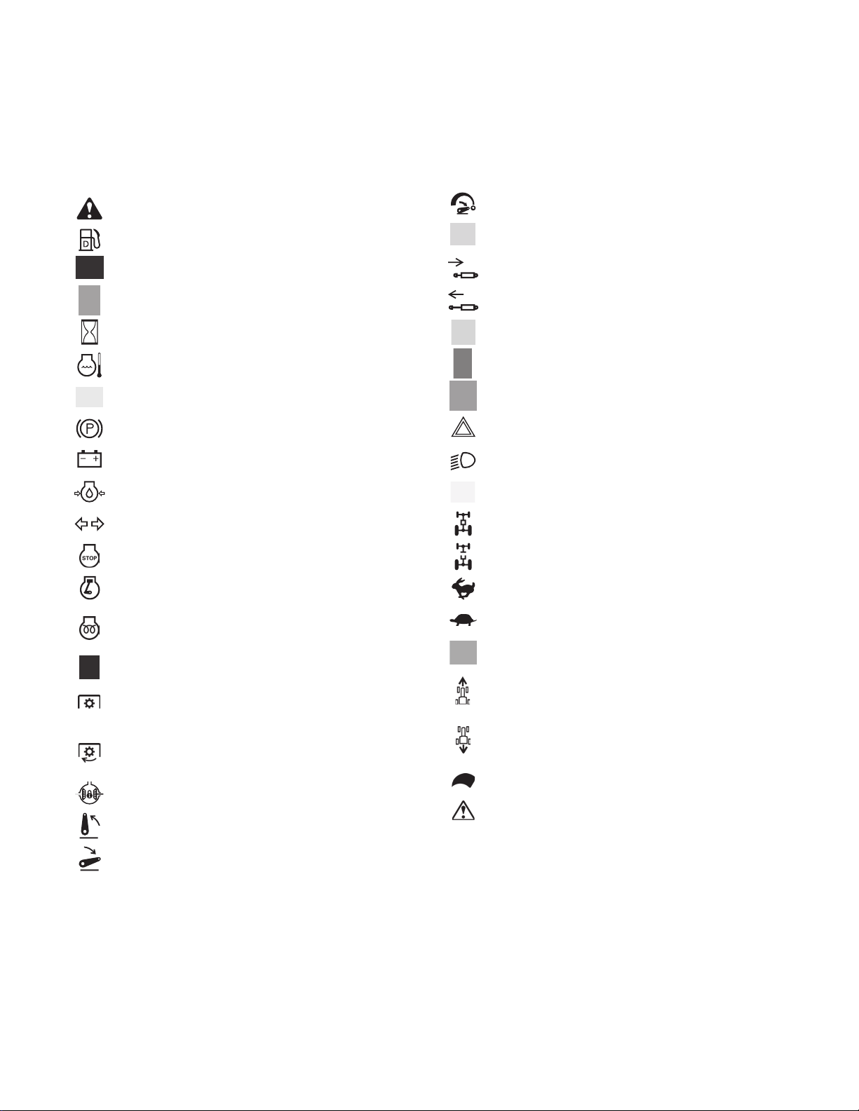
As a guide to the operation of your tractor, various universal symbols have been utilized on the instruments and
controls. The symbols are shown below with an indication of their meaning.
Safety Alert Symbol
Diesel Fuel
Fuel-Level
Engine-Rotational Speed
Hourmeter/Elapsed Operating Hours
Engine Coolant-Temperature
Brake System
Parking Brake
Battery Charging Condition
Engine Oil-Pressure
Turn Signal
Engine-Stop
Engine-Run
3-Point Lowering Speed Control
Speed Set
Remote Cylinder-Retract
Remote Cylinder-Extend
Steering Wheel-Tilt Control
Lock
Unlock
Hazard Warning Lights
Headlight
Work Light
4-Wheel Drive-On
4-Wheel Drive-Off
Fast
Diesel Preheat/Glow Plugs
(Low Temperature Start Aid)
Starter Control
Power Take-Off Control-Off Position
(Disengaged)
Power Take-Off Control-On Position
(Engaged)
Differential Lock
Position Control-Raised Position
Position Control-Lowered Position
Slow
Read Operator's Manual
Tractor-Forward Movement-Overhead View of
Machine
Tractor-Rearward Movement-Overhead View of
Machine
Engine Speed Control
Master System Warning
Page 4
FOREWORD
You are now the proud owner of a KUBOTA Tractor. This tractor is a product of
KUBOTA quality engineering and manufacturing. It is made of fine materials and
under a rigid quality control system. It will give you long, satisfactory service. To
obtain the best use of your tractor, please read this manual carefully. It will help you
become familiar with the operation of the tractor and contains many helpful hints
about tractor maintenance. It is KUBOTA's policy to utilize as quickly as possible
every advance in our research. The immediate use of new techniques in the
manufacture of products may cause some small parts of this manual to be
outdated. KUBOTA distributors and dealers will have the most up-to-date
information. Please do not hesitate to consult with them.
SAFETY FIRST
This symbol, the industry's "Safety Alert Symbol", is used throughout this manual
and on labels on the machine itself to warn of the possibility of personal injury.
Read these instructions carefully. It is essential that you read the instructions and
safety regulations before you attempt to assemble or use this unit.
DANGER :
WARNING :
CAUTION :
IMPORTANT :
NOTE : Gives helpful information.
Indicates an imminently hazardous situation which, if not
avoided, will result in death or serious injury.
Indicates a potentially hazardous situation which, if not
avoided, could result in death or serious injury.
Indicates a potentially hazardous situation which, if not
avoided, could result in minor or moderate injury.
Indicates that equipment or property damage could result if
instructions are not followed.
Page 5

CONTENTS
SAFE OPERATION ............................................................................................ -1
SERVICING OF TRACTOR......................................................................................... 1
SPECIFICATIONS....................................................................................................... 2
SPECIFICATION TABLE ......................................................................................... 2
TRAVELING SPEEDS ............................................................................................. 4
IMPLEMENT LIMITATIONS ........................................................................................ 5
INSTRUMENT PANEL AND CONTROLS................................................................... 7
PRE-OPERATION CHECK ......................................................................................... 9
DAILY CHECK ......................................................................................................... 9
OPERATING THE ENGINE....................................................................................... 10
STARTING THE ENGINE ...................................................................................... 10
Block Heater (Option) .....................................................................................................13
STOPPING THE ENGINE...................................................................................... 13
WARMING UP ....................................................................................................... 14
Warm-up Transmission Oil at Low Ambient Temperatures............................................ 14
JUMP STARTING .................................................................................................. 14
OPERATING THE TRACTOR ................................................................................... 16
OPERATING NEW TRACTOR .............................................................................. 16
Do not Operate the Tractor at Full Speed for the First 50 Hours.................................... 16
Changing Lubricating Oil for New Tractors..................................................................... 16
BOARDING AND LEAVING THE TRACTOR ........................................................ 16
OPERATING FOLDABLE ROPS ........................................................................... 16
To Fold the ROPS ..........................................................................................................16
To Raise the ROPS to Upright Position.......................................................................... 17
Adjustment of Foldable ROPS........................................................................................ 18
STARTING ............................................................................................................. 18
Operator's Seat...............................................................................................................18
Seat Belt .........................................................................................................................19
Tilt Steering Adjustment..................................................................................................19
Head Light / Turn Signal / Hazard Light Switch..............................................................20
Tractor Lights..................................................................................................................21
Brake Pedals (Right and Left).........................................................................................21
Range Gear Shift Lever (L-M-H).....................................................................................22
Front Wheel Drive Lever.................................................................................................23
Hand Throttle Lever........................................................................................................23
Parking Brake .................................................................................................................23
Speed Control Pedal....................................................................................................... 24
Speed Set Device...........................................................................................................24
STOPPING............................................................................................................. 25
Stopping..........................................................................................................................25
CHECK DURING DRIVING ................................................................................... 25
Immediately Stop the Engine if:......................................................................................25
Easy Checker (TM)......................................................................................................... 25
Page 6

CONTENTS
Fuel Gauge.....................................................................................................................26
Coolant Temperature Gauge..........................................................................................26
Hourmeter / Tachometer.................................................................................................27
PARKING ............................................................................................................... 27
Parking............................................................................................................................27
OPERATING TECHNIQUES ................................................................................. 28
Differential Lock..............................................................................................................28
Operating the Tractor on a Road....................................................................................28
Operating on Slopes or Rough Terrain...........................................................................29
Transport the Tractor Safely...........................................................................................29
Directions for Use of Power Steering..............................................................................29
Electrical Outlet...............................................................................................................29
PTO ........................................................................................................................... 30
PTO OPERATION.................................................................................................. 30
PTO Select Lever ...........................................................................................................30
PTO Clutch Lever ...........................................................................................................31
Stationary PTO ...............................................................................................................31
3-POINT HITCH & DRAWBAR.................................................................................. 32
3-POINT HITCH ..................................................................................................... 33
Selecting the holes of lifting rods and lower links ........................................................... 33
Selecting the Top Link Mounting Holes ..........................................................................33
Drawbar ..........................................................................................................................33
Lifting Rod (Right)...........................................................................................................33
Top Link..........................................................................................................................33
Telescopic Stabilizers.....................................................................................................34
DRAWBAR............................................................................................................. 34
Adjusting Drawbar Length ..............................................................................................34
HYDRAULIC UNIT..................................................................................................... 35
3-POINT HITCH CONTROL SYSTEM................................................................... 35
Position Control ..............................................................................................................35
3-point Hitch Lowering Speed.........................................................................................35
AUXILIARY HYDRAULICS .................................................................................... 36
Hydraulic Block Type Outlet ...........................................................................................36
DUAL REMOTE HYDRAULIC CONTROL SYSTEM ............................................. 36
Control Lever and Hydraulic Hose Connections............................................................. 36
Loader / Remote Control Valve Lever ............................................................................37
Valve Lock ......................................................................................................................37
Hydraulic Control Unit Use Reference Chart.................................................................. 38
TIRES, WHEELS AND BALLAST.............................................................................. 39
TIRES..................................................................................................................... 39
Inflation Pressure............................................................................................................39
Dual Tires ....................................................................................................................... 39
WHEEL ADJUSTMENT ......................................................................................... 39
Front Wheels ..................................................................................................................40
Rear Wheels...................................................................................................................40
Treads.............................................................................................................................41
BALLAST ............................................................................................................... 44
Front Ballast.................................................................................................................... 44
Rear Ballast ....................................................................................................................44
Page 7

CONTENTS
MAINTENANCE......................................................................................................... 45
SERVICE INTERVALS .......................................................................................... 45
LUBRICANTS, FUEL AND COOLANT .................................................................. 47
PERIODIC SERVICE................................................................................................. 50
HOW TO OPEN THE HOOD ................................................................................. 50
Hood ...............................................................................................................................50
Engine Side Cover..........................................................................................................51
DAILY CHECK ....................................................................................................... 51
Walk Around Inspection..................................................................................................51
Checking and Refueling..................................................................................................51
Checking Engine Oil Level.............................................................................................. 52
Checking Transmission Fluid Level................................................................................52
Checking Coolant Level..................................................................................................53
Cleaning Evacuator Valve ..............................................................................................53
Cleaning Grill and Radiator Screen ................................................................................53
Checking Brake Pedal ....................................................................................................54
Checking Gauges, Meter and Easy Checker (TM) ......................................................... 54
Checking Head Light, Hazard Light etc. .........................................................................54
Checking Seat Belt and ROPS.......................................................................................54
Checking and Cleaning of Electrical Wiring and Battery Cables .................................... 54
Checking Movable Parts................................................................................................. 54
EVERY 50 HOURS ................................................................................................ 55
Lubricating Grease Fittings............................................................................................. 55
Checking Engine Start System.......................................................................................55
Checking Wheel Bolt Torque..........................................................................................56
EVERY 100 HOURS .............................................................................................. 56
Checking Battery Condition ............................................................................................56
Cleaning Air Cleaner Primary Element ........................................................................... 58
Cleaning Fuel Filter......................................................................................................... 58
Adjusting Fan Belt Tension............................................................................................. 59
Adjusting Brake Pedal ....................................................................................................60
EVERY 200 HOURS .............................................................................................. 60
Replacing Engine Oil Filter .............................................................................................60
Changing Engine Oil....................................................................................................... 61
Replacing Transmission Oil Filter [HST]......................................................................... 61
Adjusting Toe-in.............................................................................................................. 62
EVERY 400 HOURS .............................................................................................. 62
Changing Transmission Fluid ......................................................................................... 62
Replacing Hydraulic Oil Filter .........................................................................................63
Adjusting Front Axle Pivot [4WD]....................................................................................64
Replacing Fuel Filter Element.........................................................................................64
Changing Front Axle Case Oil ........................................................................................65
EVERY 800 HOURS .............................................................................................. 65
Adjusting Engine Valve Clearance .................................................................................65
EVERY 1000 HOURS or 1 YEAR .......................................................................... 65
Replacing Air Cleaner Primary Element and Secondary Element.................................. 65
EVERY 1 500 HOURS ........................................................................................... 65
Checking Fuel Injection Nozzle Injection Pressure.........................................................65
EVERY 2000 HOURS or 2 YEARS........................................................................ 65
Flushing Cooling System and Changing Coolant ........................................................... 65
Anti-Freeze .....................................................................................................................66
Page 8

CONTENTS
EVERY 3 000 HOURS ........................................................................................... 67
Checking Injection Pump................................................................................................67
EVERY 1 YEAR ..................................................................................................... 67
Checking Radiator Hoses and Clamps...........................................................................67
Checking Intake Air Line................................................................................................. 67
Checking Fuel Lines .......................................................................................................68
EVERY 2 YEARS................................................................................................... 68
Flushing Cooling System and Changing Coolant ........................................................... 68
Anti-Freeze .....................................................................................................................69
Replacing Radiator Hose (Water pipes) .........................................................................70
Replacing Fuel Hose ......................................................................................................70
Replacing Intake Air Line................................................................................................ 70
EVERY 4 YEARS................................................................................................... 70
Replacing Radiator Hose (Water pipes) .........................................................................70
Replacing Fuel Lines ......................................................................................................70
Replacing Intake Air Line................................................................................................ 70
SERVICE AS REQUIRED...................................................................................... 70
Bleeding Fuel System..................................................................................................... 70
Draining Clutch Housing Water ......................................................................................70
Replacing Fuse...............................................................................................................71
Replacing Light Bulb.......................................................................................................71
Replacing Radiator Hose (Water pipes) .........................................................................71
Replacing Fuel Lines ......................................................................................................71
Replacing Intake Air Line................................................................................................ 71
STORAGE ................................................................................................................. 72
TRACTOR STORAGE ........................................................................................... 72
REMOVING THE TRACTOR FROM STORAGE................................................... 72
TROUBLESHOOTING............................................................................................... 73
ENGINE TROUBLESHOOTING ............................................................................ 73
OPTIONS................................................................................................................... 74
APPENDICES............................................................................................................ 75
INDEX .................................................................................................................... 75
Page 9
SAFE OPERATION
-1SAFE OPERATION
Careful operation is your best insurance against an
accident.
Read and understand this manual carefully before
operating the tractor.
All operators, no matter how much experience they may
have, should read this and other related manuals before
operating the tractor or any implement attached to it. It is
the owner's obligation to instruct all operators in safe
operation.
1. BEFORE OPERATING THE TRACTOR
1. Know your equipment and its limitations. Read this
entire manual before attempting to start and operate
the tractor.
2. Pay special attention to the danger, warning and
caution labels on the tractor.
3. Do not operate the tractor or any implement attached
to it while under the influence of alcohol, medication,
controlled substances or while fatigued.
4. Before allowing other people to use your tractor,
explain how to operate and have them read this
manual before operation.
5. Never wear loose, torn, or bulky clothing around
tractor. It may catch on moving parts or controls,
leading to the risk of an accident. Use additional safety
items, e.g. hard hat, safety boots or shoes, eye and
hearing protection, gloves, etc., as appropriate or
required.
6. Do not allow passengers to ride on any part of the
tractor at anytime. The operator must remain in the
tractor seat during operation.
7. Check brakes, clutch, linkage pins and other
mechanical parts for improper adjustment and wear.
Replace worn or damaged parts promptly. Check the
tightness of all nuts and bolts regularly. (For further
details, see "MAINTENANCE" section.)
8. Keep your tractor clean. Dirt, grease, and trash build
up may contribute to fires and lead to personal injury.
9. Use only implements meeting the specifications listed
under "IMPLEMENT LIMITATIONS" in this manual or
implements approved by KUBOTA.
10.Use proper weights on the front or rear of the tractor to
reduce the risk of upsets. When using the front loader,
put an implement or ballast on the 3-point hitch to
improve stability. Follow the safe operating
procedures specified in the implement or attachment
manual.
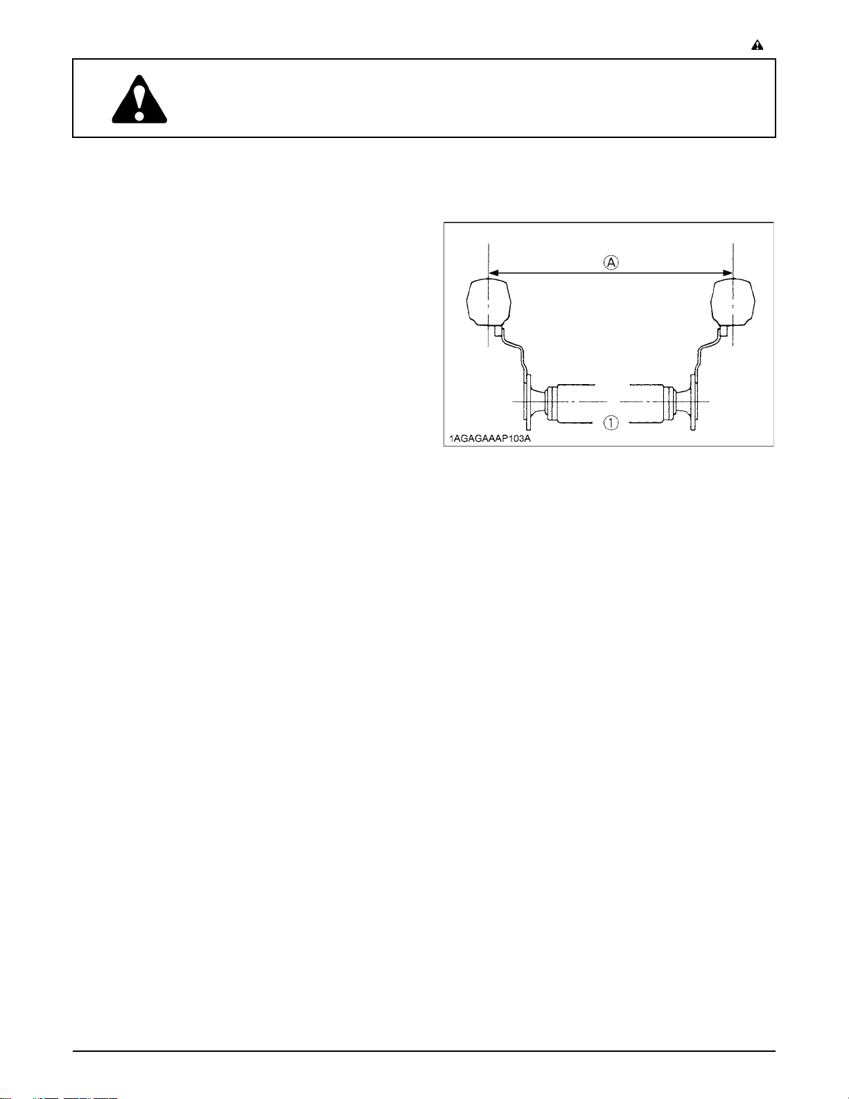
11. The narrower the tread, the greater the risk of a tractor
upset. For maximum stability, adjust the wheels to the
widest practical tread width for your application. (See
"TIRES, WHEELS AND BALLAST" section.)
(1) Rear wheels (A) Tread Width
12.Do not modify the tractor. Unauthorized modification
may affect the function of the tractor, which may result
in personal injury.
C CAB, ROPS
1. KUBOTA recommends the use of a CAB or Roll Over
Protective Structures (ROPS) and seat belt in almost
all applications. This combination will reduce the risk
of serious injury or death, should the tractor be upset.
Check for overhead clearance which may interfere
with a CAB or ROPS.
2. Set parking brake and stop engine. Remove any
obstruction that may prevent raising or folding of the
ROPS. Do not allow any bystanders. Always perform
function from a stable position at the rear of the tractor.
Hold the top of the ROPS securely when raising or
folding. Make sure all pins are installed and locked.
3. If the CAB or ROPS is loosened or removed for any
reason, make sure that all parts are reinstalled
correctly before operating the tractor.
4. Never modify or repair any structural member of a
CAB or ROPS because welding, bending, drilling,
grinding, or cutting may weaken the structure.
5. If any structural member of the CAB or ROPS is
damaged, replace the entire structure at your local
KUBOTA Dealer.
6. If the tractor is equipped with a foldable ROPS it may
be temporarily folded down only when absolutely
necessary for areas with height constraints.
(There is no operator protection provided by the ROPS
in the folded position. For operator safety the ROPS
should be placed in the upright and locked position
and the seat belt fastened for all other operations.)
Page 10
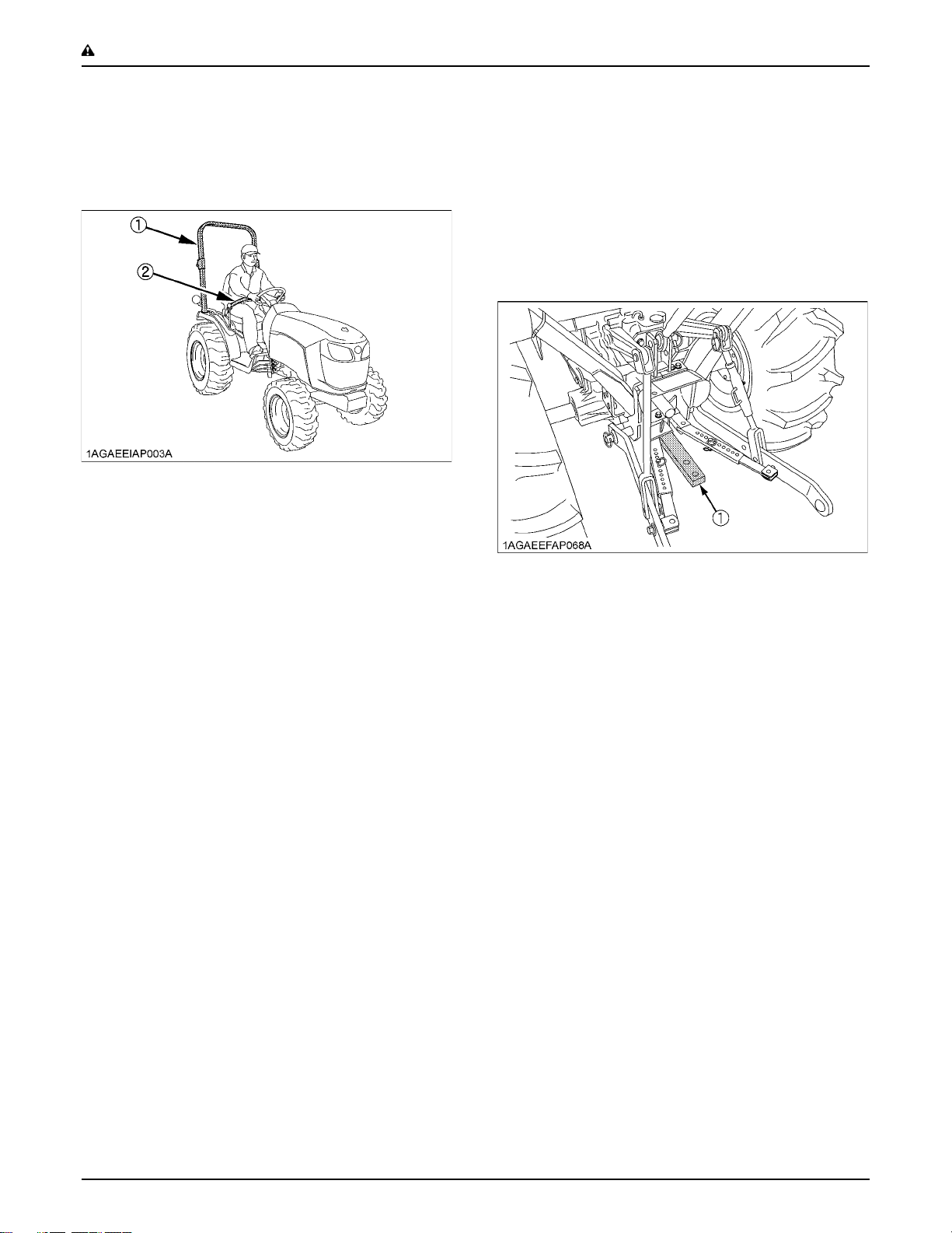
SAFE OPERATION-2
7. Always use the seat belt if the tractor has a CAB or
ROPS.
Do not use the seat belt if a foldable ROPS is down or
there is no ROPS. Check the seat belt regularly and
replace if frayed or damaged.
(1) ROPS
(2) Seat belt
2. OPERATING THE TRACTOR
Operator safety is a priority. Safe operation, specifically
with respect to overturning hazards, entails understanding
the equipment and environmental conditions at the time of
use. Some prohibited uses which can affect overturning
hazards include traveling and turning with implements
and loads carried too high etc. This manual sets forth
some of the obvious risks, but the list is not, and cannot
be, exhaustive. It is the operator's responsibility to be alert
for any equipment or environmental condition that could
compromise safe operation.
C Starting
1. Always sit in the operator's seat when starting engine
or operating levers or controls. Adjust seat per
instructions in the operating the tractor section. Never
start engine while standing on the ground.
2. Before starting the engine, make sure that all levers
(including auxiliary control levers) are in their neutral
positions, that the parking brake is engaged, and that
both the clutch and the Power Take-Off (PTO) are
disengaged or "OFF".
Fasten the seat belt if the tractor has a CAB or a
foldable ROPS in the upright and locked position.
3. Do not start engine by shorting across starter
terminals or bypassing the safety start switch.
Machine may start in gear and move if normal starting
circuitry is bypassed.
4. Do not operate or idle engine in a non-ventilated area.
Carbon monoxide gas is colorless, odorless, and
deadly.
5. Check before each use that operator presence
controls are functioning correctly. Test safety systems.
(See "Checking Engine Start System" in "EVERY 50
HOURS" in "PERIODIC SERVICE" section.)
Do not operate unless they are functioning correctly.
C Working
1. Pull only from the drawbar. Never hitch to axle housing
or any other point except drawbar; such arrangements
will increase the risk of serious personal injury or death
due to a tractor upset.
(1) Drawbar
2. For trailing PTO-driven implements, set the drawbar to
the towing position.
3. Attach pulled or towed loads to the drawbar only.
4. Keep all shields and guards in place. Replace any that
are missing or damaged.
5. Avoid sudden starts. To avoid upsets, slow down
when turning, on uneven ground, and before stopping.
6. The tractor cannot turn with the differential locked and
attempting to do so could be dangerous.
7. Do not operate near ditches, holes, embankments, or
other ground surface features which may collapse
under the tractor's weight. The risk of tractor upset is
even higher when the ground is loose or wet. Tall
grass can hide obstacles, walk the area first to be sure.
8. Watch where you are going at all times. Watch for and
avoid obstacles. Be alert at row ends, near trees, and
other obstructions.
9. When working in groups, always let the others know
what you are going to do before you do it.
10.Never try to get on or off a moving tractor.
11.Always sit in the operator's seat when operating levers
or controls.
12.Do not stand between tractor and implement or trailed
vehicle unless parking brake is applied.
C Safety for children
Tragedy can occur if the operator is not alert to the
presence of children. Children generally are attracted to
machines and the work they do.
1. Never assume that children will remain where you last
saw them.
Page 11
2. Keep children out of the work area and under the
watchful eye of another responsible adult.
3. Be alert and shut your machine down if children enter
the work area.
4. Never carry children on your machine. There is no safe
place for them to ride. They may fall off and be run
over or interfere with your control of the machine.
5. Never allow children to operate the machine even
under adult supervision.
6. Never allow children to play on the machine or on the
implement.
7. Use extra caution when backing up. Look behind and
down to make sure area is clear before moving.
C Operating on slopes
Slopes are a major factor related to loss-of-control and tipover accidents, which can result in severe injury or death.
All slopes require extra caution.
1. To avoid upsets, always back up steep slopes. If you
cannot back up the slope or if you feel uneasy on it, do
not operate on it. Stay off slopes too steep for safe
operation.
2. Driving forward out of a ditch, mired condition or up a
steep slope increases the risk of a tractor to be upset
backward. Always back out of these situations. Extra
caution is required with 4-wheel drive models because
their increased traction can give the operator false
confidence in the tractor's ability to climb slopes.
3. Keep all movement on slopes slow and gradual. Do
not make sudden changes in speed, direction or apply
brake and make sudden motions of the steering
wheel.
4. Avoid disengaging the clutch or changing gears speed
when climbing or going down a slope. If on a slope
disengaging the clutch or changing gears to neutral
could cause loss of control.
5. Special attention should be made to the weight and
location of implements and loads as such will affect the
stability of the tractor.
6. To improve stability on slope, set widest wheel tread
as shown in "TIRES, WHEELS AND BALLAST"
section.
Follow recommendations for proper ballasting.
C Driving the tractor on the road
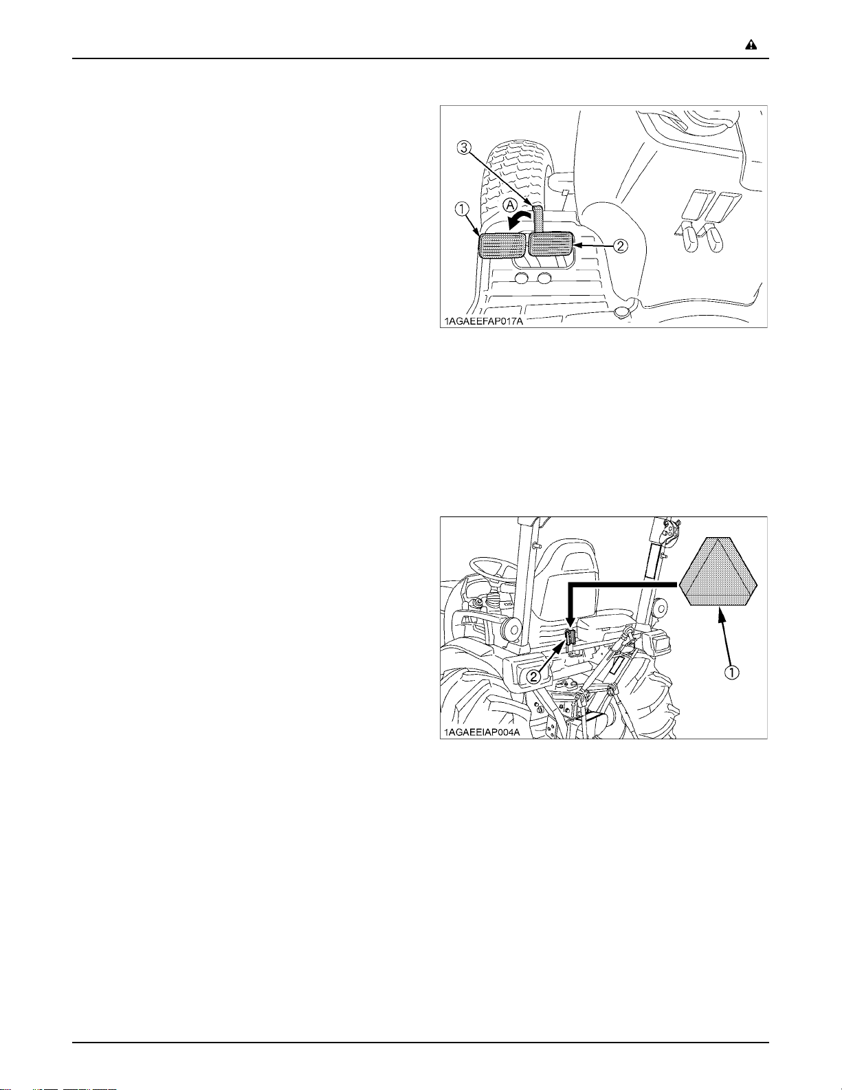
1. Lock the 2 brake pedals together to help assure
straight-line stops. Uneven braking at road speeds
could cause the tractor to tip over.
-3SAFE OPERATION
(1) Brake Pedal (LH)
(2) Brake Pedal (RH)
(3) Brake Pedal Lock
(A) Whenever travelling on the road
2. Check the front wheel engagement. The braking
characteristics are different between 2 and 4-wheel
drive. Be aware of the difference and use carefully.
3. Always slow the tractor down before turning. Turning
at high speed may tip the tractor over.
4. Make sure that the Slow Moving Vehicle (SMV) sign is
clean and visible. Use hazard lights and turn signals as
required.
(1) SMV emblem
(2) Bracket
5. Observe all local traffic and safety regulations.
6. Turn the headlights on. Dim them when meeting
another vehicle.
7. Drive at speeds that allow you to maintain control at all
times.
8. Do not apply the differential lock while traveling at road
speeds. The tractor may run out of control.
9. Avoid sudden motions of the steering wheel as they
can lead to a dangerous loss of stability. The risk is
especially great when the tractor is traveling at road
speeds.
Page 12
SAFE OPERATION-4
10.Keep the ROPS in the "UP" position and wear the seat
belt when driving the tractor on the road.
Otherwise, you will not be protected in the event of a
tractor roll-over.
11.Do not operate an implement while the tractor is on the
road. Lock the 3-point hitch in the raised position.
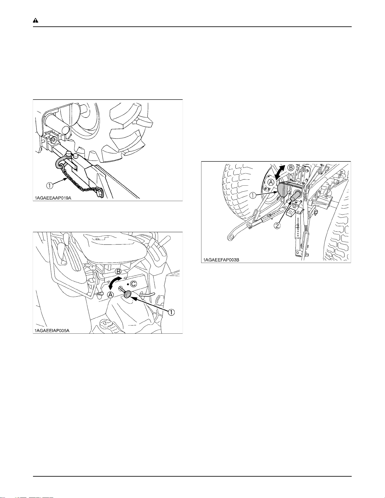
12.When towing other equipment, use a safety chain and
place an SMV emblem on it as well.
(1) Safety chain
13.Set the implement lowering speed knob in the "LOCK"
position to hold the implement in the raised position.
3. Avoid parking on steep slopes, if at all possible park on
a firm and level surface; if not, park across a slope and
chock the wheels.
Failure to comply with this warning may allow the
tractor to move and could cause injury or death.
4. OPERATING THE PTO
1. Wait until all moving components have completely
stopped before getting off the tractor, connecting,
disconnecting, adjusting, cleaning, or servicing any
PTO driven equipment.
2. Keep the PTO shaft cover in place at all times.
Replace the PTO shaft cap when the shaft is not in
use.
(1) 3-point hitch lowering speed knob (A) "FAST"
(B) "SLOW"
(C) "LOCK"
3. PARKING THE TRACTOR
1. Disengage the PTO, lower all implements to the
ground, place all control levers in their neutral
positions, set the parking brake, stop the engine,
remove the key from the ignition and lock the cab door
(if equipped). Leaving transmission in gear with the
engine stopped will not prevent tractor from rolling.
2. Make sure that the tractor has come to a complete
stop before dismounting.
(1) PTO Shaft cover
(2) PTO Shaft cap
(A) "NORMAL POSITION"
(B) "RAISED POSITION"
3. Before installing or using PTO driven equipment, read
the manufacturer's manual and review the safety
labels attached to the equipment.
4. When operating stationary PTO driven equipment,
always apply the tractor parking brake and place
chocks behind and in front of the rear wheels. Stay
clear of all rotating parts. Never step over rotating
parts.
5. USING 3-POINT HITCH
1. Use the 3-point hitch only with equipment designed for
3-point hitch usage.
2. When using a 3-point hitch mounted implement, be
sure to install the proper counterbalance weight on the
front of the tractor.
3. When transporting on the road, set the implement
lowering speed knob in the "LOCK" position to hold the
implement in the raised position.
Page 13
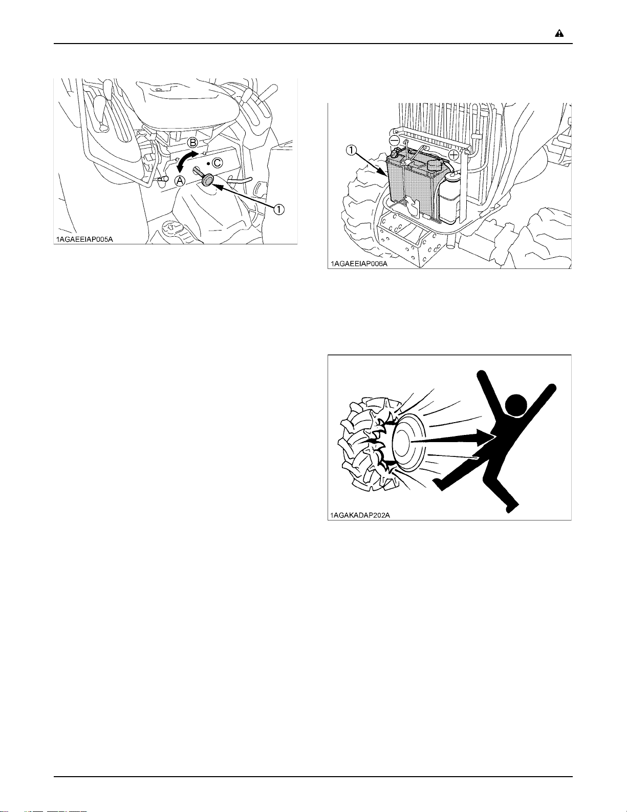
(1) 3-point hitch lowering speed knob (A) "FAST"
(B) "SLOW"
(C) "LOCK"
6. SERVICING THE TRACTOR
Before servicing the tractor, park it on a firm, flat and level
surface, set the parking brake, lower all implements to the
ground, place the gear shift lever in neutral, stop the
engine and remove the key.
1. Allow the tractor time to cool off before working on or
near the engine, muffler, radiator, etc.
2. Do not remove radiator cap while coolant is hot. When
cool, slowly rotate cap to the first stop and allow
sufficient time for excess pressure to escape before
removing the cap completely. If the tractor has a
coolant recovery tank, add coolant or water to the tank,
not the radiator. (See "Checking Coolant Level" in
"DAILY CHECK" in "PERIODIC SERVICE" section.)
3. Always stop the engine before refueling. Avoid spills
and overfilling.
4. Do not smoke when working around battery or when
refueling. Keep all sparks and flames away from
battery and fuel tank. The battery presents an
explosive hazard, because it gives off hydrogen and
oxygen especially when recharging.
5. Before "jump starting" a dead battery, read and follow
all of the instructions. (See "JUMP STARTING" in
"OPERATING THE ENGINE" section.)
6. Keep first aid kit and fire extinguisher handy at all
times.
7. Disconnect the battery's ground cable before working
on or near electric components.
8. To avoid the possibility of battery explosion, do not use
or charge the refillable type battery if the fluid level is
below the LOWER ( lower limit level ) mark. Check the
fluid level regularly and add distilled water as required
so that the fluid level is between the UPPER and
LOWER levels.
-5SAFE OPERATION
9. To avoid sparks from an accidental short circuit,
always disconnect the battery's ground cable (-) first
and reconnect it last.
(1) Battery
10.Do not attempt to mount a tire on a rim. This should be
done by a qualified person with the proper equipment.
11.Always maintain the correct tire pressure. Do not
inflate tires above the recommended pressure shown
in the operator's manual.
12.Securely support the tractor when either changing
wheels or adjusting the wheel tread width.
13.Make sure that wheel bolts have been tightened to the
specified torque.
14.Do not work under any hydraulically supported
devices. They can settle, suddenly leak down, or be
accidentally lowered. If it is necessary to work under
tractor or any machine elements for servicing or
adjustment, securely support them with stands or
suitable blocking beforehand.
Page 14
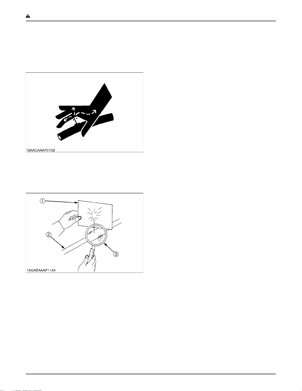
SAFE OPERATION-6
15.Escaping hydraulic fluid under pressure has sufficient
force to penetrate skin, causing serious personal
injury. Before disconnecting hydraulic lines, be sure to
release all residual pressure. Before applying
pressure to the hydraulic system, make sure that all
connections are tight and that all lines, pipes, and
hoses are free of damage.
16.Fluid escaping from pinholes may be invisible. Do not
use hands to search for suspected leaks; use a piece
of cardboard or wood. Use of safety goggles or other
eye protection is also highly recommended. If injured
by escaping fluid, see a medical doctor at once. This
fluid will produce gangrene or severe allergic reaction.
(1) Cardboard
(2) Hydraulic line
(3) Magnifying glass
Page 15
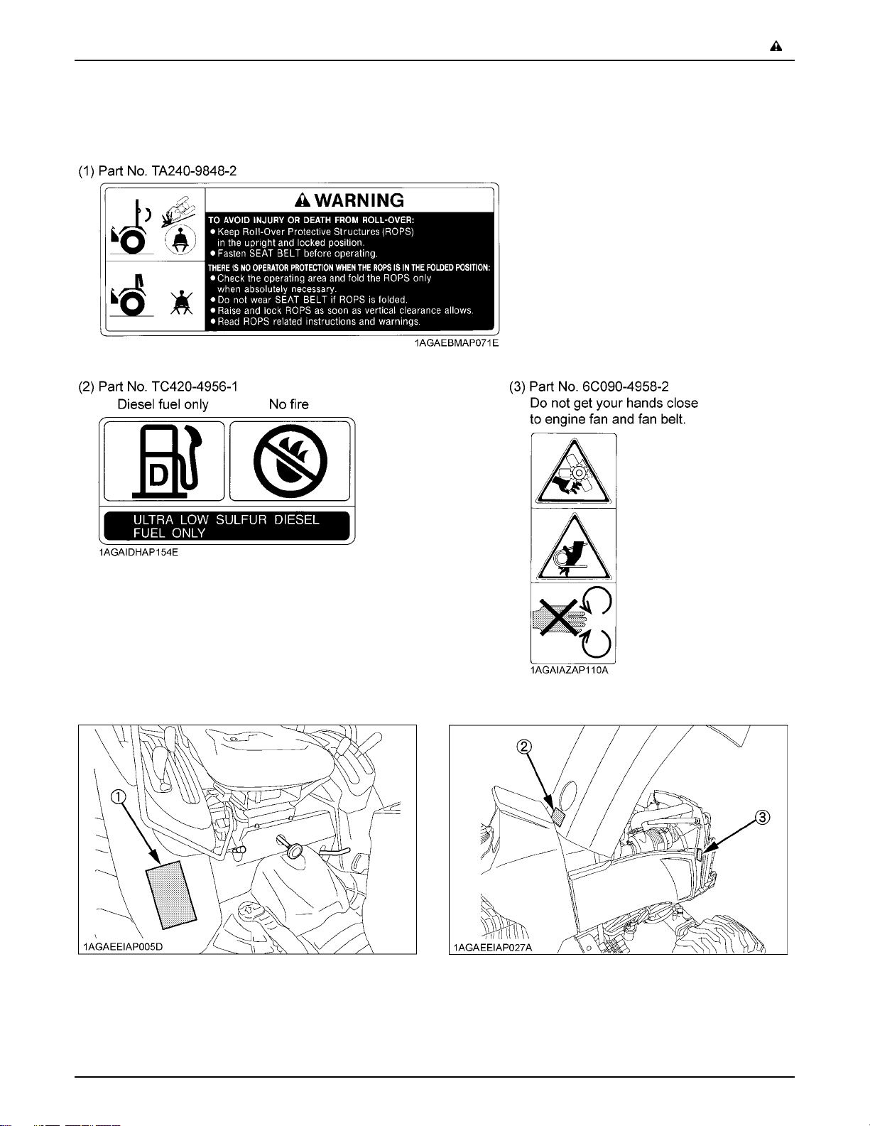
7. DANGER, WARNING AND CAUTION LABELS
-7SAFE OPERATION
Page 16
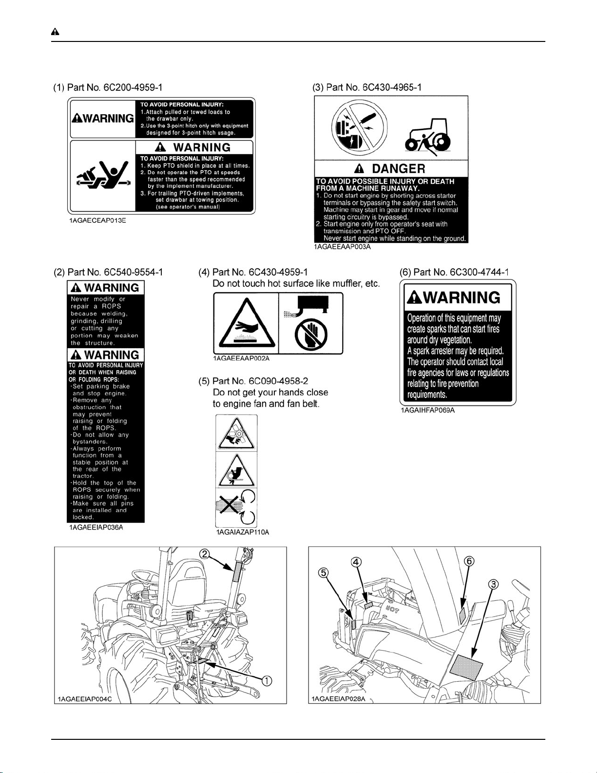
SAFE OPERATION-8
Page 17
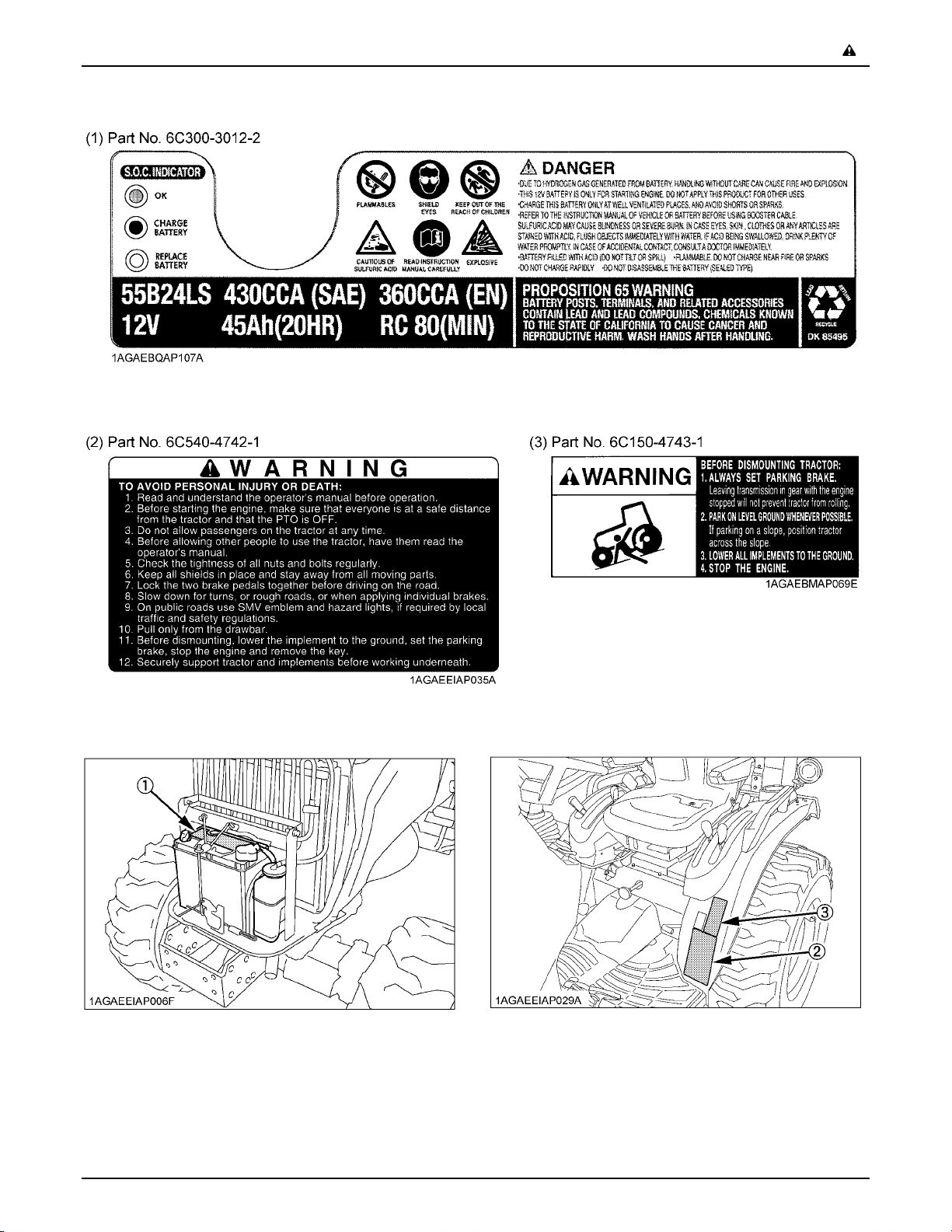
-9SAFE OPERATION
Page 18

SAFE OPERATION-10
8. CARE OF DANGER, WARNING AND CAUTION LABELS
1. Keep danger, warning and caution labels clean and free from obstructing material.
2. Clean danger, warning and caution labels with soap and water, dry with a soft cloth.
3. Replace damaged or missing danger, warning and caution labels with new labels from your local KUBOTA Dealer.
4. If a component with danger, warning and caution label(s) affixed is replaced with new part, make sure new label(s) is
(are) attached in the same location(s) as the replaced component.
5. Mount new danger, warning and caution labels by applying on a clean dry surface and pressing any bubbles to outside
edge.
Page 19
SERVICING OF TRACTOR
Your dealer is interested in your new tractor and has the
desire to help you get the most value from it. After reading
this manual thoroughly, you will find that you can do some
of the regular maintenance yourself.
However, when in need of parts or major service, be sure
to see your KUBOTA Dealer.
For service, contact the KUBOTA Dealership from which
you purchased your tractor or your local KUBOTA Dealer.
When in need of parts, be prepared to give your dealer the
tractor, CAB/ROPS and engine serial numbers.
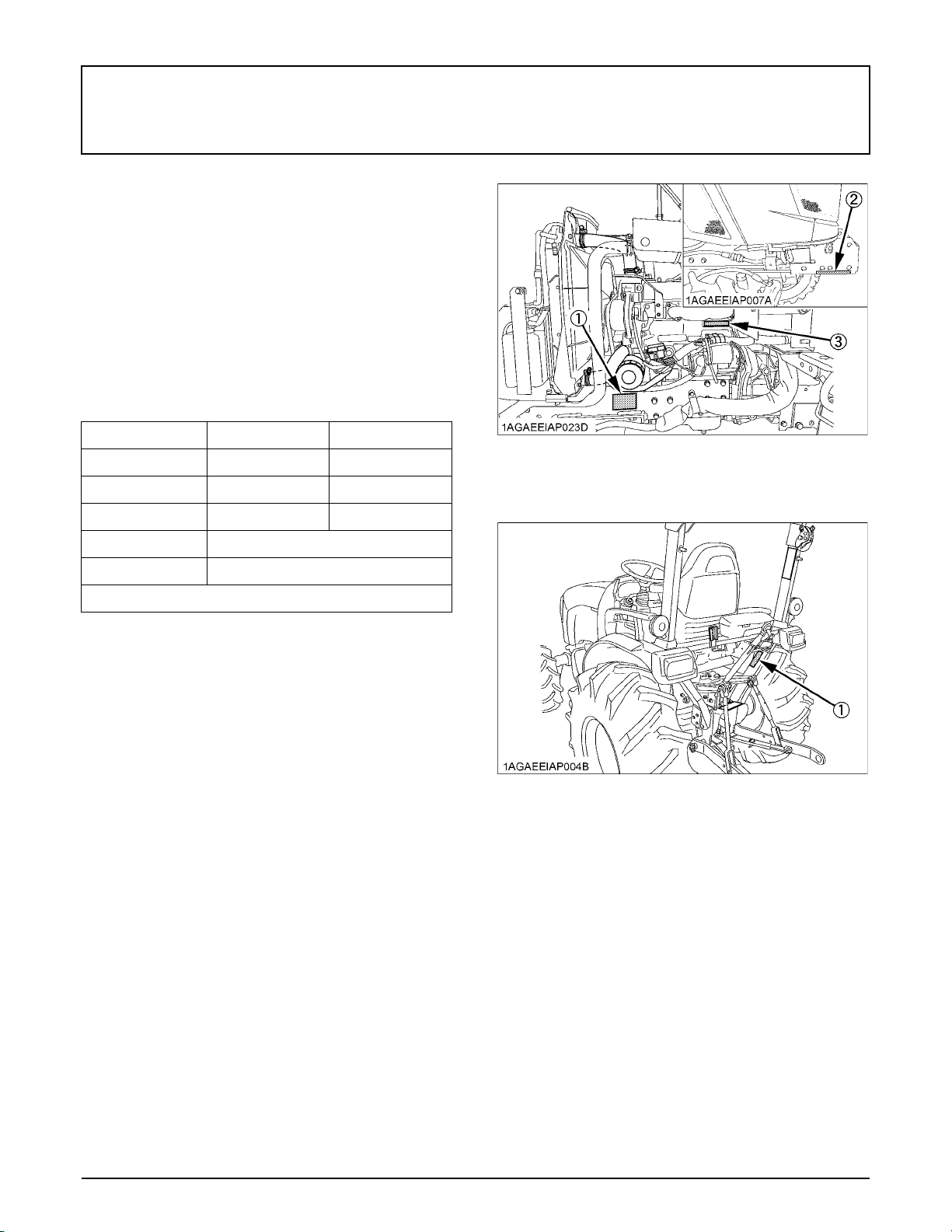
Locate the serial numbers now and record them in the
space provided.
Type Serial No.
Tractor
CAB / ROPS
(1) Tractor identification plate
(2) Tractor serial number
(3) Engine serial number
1SERVICING OF TRACTOR
Engine
Date of Purchase
Name of Dealer
(To be filled in by purchaser)
C Warranty
This tractor is warranted under the KUBOTA Limited
Express Warranty, a copy of which may be obtained from
your selling dealer. No warranty shall, however, apply if
the tractor has not been handled according to the
instruction given in the Operator's Manual even it is within
the warranty period.
C Scrapping the tractor and its procedure
To put the tractor out of service, correctly follow the local
rules and regulations of the country or territory where you
scrap it. If you have questions, consult your local
KUBOTA Dealer.
(1) ROPS identification (ROPS Serial No.)
Page 20
2 SPECIFICATIONS
SPECIFICATIONS
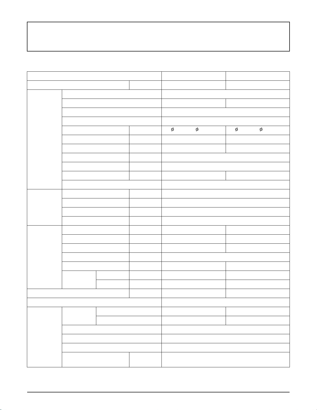
SPECIFICATION TABLE
Model B2301HSD B2601HSD
PTO power kW (HP) 13.0 (17.5)* 14.5 (19.5)*
Maker KUBOTA
Model D1005-E4-D32 D1105-E4-D32
Type E-TVCS, liquid cooled, 3-cylinder diesel
Number of cylinders 3
Bore and stroke mm (in.) 76x73.6 ( 3.0x2.9) 78x78.4 ( 3.1x3.1)
Engine
Capacities
Dimensions
Total displacement cc (cu.in.) 1001 (61.1) 1123 (68.5)
Engine gross power kW (HP) 16.4 (22)* 19.0 (25.5)*
Rated revolution rpm 2800
Low idling revolution rpm 1000 to 1100
Maximum torque N-m (ft-lb) 60 (44) 71 (52)
Battery 12V, RC : 80min, CCA : 430A
Fuel tank L (U.S.gals.) 23 (6.1)
Engine crankcase (with filter) L (U.S.qts.) 3.1 (3.3)
Engine coolant L (U.S.qts.) 3.8 (4.0)
Transmission case L (U.S.gals.) 15 (4.0)
Overall length (without 3P) mm (in.) 2380 (93.7) 2410 (94.9)
Overall width (min. tread) mm (in.) 1150 (45.3) 1245 (49.0)
Overall height mm (in.) 2130 (83.9) 2160 (85.0)
Wheel base mm (in.) 1560 (61.4)
Minimum ground clearance mm (in.) 305 (12.0) 325 (12.8)
Front mm (in.) 830 (32.7) 850 (33.5)
Tread
Rear mm (in.) 900 (35.5) 950 (37.4)
Weight kg (lbs.) 710 (1566) 740 (1632)
Clutch Not applicable
Front 6-12 7-12
Rear 9.5-16 11.2-16
m (feet) 2.1 (6.9)
Traveling
system
Tires
Steering Hydrostatic type power steering
Transmission HST (3 ranges)
Brake Dry single plate
Minimum turning radius
(with brake)
Page 21

Model B2301HSD B2601HSD
Hydraulic control system Position control
3SPECIFICATIONS
Pump capacity
Hydraulic unit
PTO
NOTE: * SAE J1995 The company reserves the right to change the specifications without notice.
3-point hitch SAE Category 1
At lift points kg (lbs.) 820 (1808)
Max. lift force
Rear-PTO SAE 1-3/8, 6 splines
PTO / Engine speed rpm
Mid-PTO USA No. 5 (KUBOTA 10-tooth) involute spline
PTO / Engine speed rpm
24 in.behind
lift point
L / min
(gals / min)
kg (lbs.) 640 (1411)
31.4 (8.3)
1 speed
540 / 2768
1 speed
2500 / 2753
Page 22

4 SPECIFICATIONS
TRAVELING SPEEDS
(At rated engine rpm)
Model B2301HSD
Tire size (Rear) 9.5 - 16 Farm / 33 x 12.5 - 15 Turf / 12 - 16.5 Industry
Range gear shift lever km / h mph
Low 0 to 5.6 0 to 3.5
Forward
Reverse
Model B2601HSD
Tire size (Rear) 11.2 - 16 Farm 33 x 12.5 - 15 Turf / 12 - 16.5 Industry
Range gear shift lever km / h mph km / h mph
Forward
Reverse
The company reserves the right to change the specification without notice.
Middle 0 to 8.8 0 to 5.5
High 0 to 19.1 0 to 11.8
Low 0 to 4.2 0 to 2.6
Middle 0 to 6.6 0 to 4.1
High 0 to 14.3 0 to 8.9
Low 0 to 6.0 0 to 3.7 0 to 5.6 0 to 3.5
Middle 0 to 9.5 0 to 5.9 0 to 8.8 0 to 5.5
High 0 to 20.4 0 to 12.7 0 to 19.1 0 to 11.8
Low 0 to 4.5 0 to 2.8 0 to 4.2 0 to 2.6
Middle 0 to 7.1 0 to 4.4 0 to 6.6 0 to 4.1
High 0 to 15.3 0 to 9.5 0 to 14.3 0 to 8.9
Page 23
IMPLEMENT LIMITATIONS
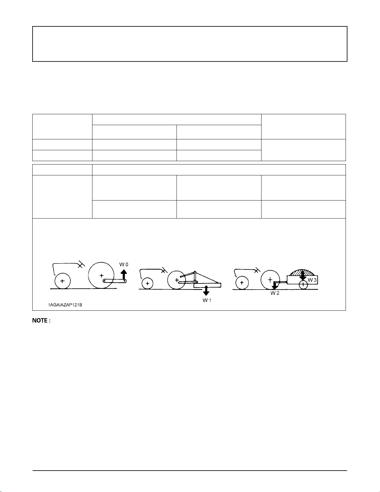
The KUBOTA Tractor has been thoroughly tested for proper performance with implements sold or approved by KUBOTA.
Use with implements which are not sold or approved by KUBOTA and which exceed the maximum specifications listed
below, or which are otherwise unfit for use with the KUBOTA Tractor may result in malfunctions or failures of the tractor,
damage to other property and injury to the operator or others. (Any malfunctions or failures of the tractor resulting from use
with improper implements are not covered by the warranty.)
Tread (max.width) with farm tires Lower link end max.
Front Rear
loading weight
W0
5IMPLEMENT LIMITATIONS
B2301HSD 830 mm (32.7 in.) 900 mm (35.4 in.)
B2601HSD 850 mm (33.5 in.) 950 mm (37.4 in.)
Actual figures
Implement weight W1
B2301
B2601
Lower link end max. loading weight........The max. allowable load which can be put on the lower link end : W0
Implement weight....................................The implement's weight which can be put on the lower link : W1
Max. drawbar load...................................W2
Trailer loading weight .............................The max. loading weight for trailer (without trailer's weight) : W3
and / or size
As in the following list
(Shown on the next page)
Max. Drawbar
Load W2
300 kg (660 lbs.) 1000 kg (2210 lbs.)
300 kg (660 lbs.)
Trailer loading weight
W3
Max. capacity
A Implement size may vary depending on soil operating conditions.
A Strictly follow the instructions outlined in the operator’s manual of the mounted or trailed machinery or trailer, and do
not operate the combination tractor - machine or tractor - trailer unless all instructions have been followed.
A Forestry Application
Following hazards exist;
(a) toppling trees, primarily in case a rear-mounted tree grab-crane is mounted at the rear of the tractor;
(b) penetrating objects in the operator’s enclosure, primarily in case a winch is mounted at the rear of the tractor.
Optional equipments such as OPS (Operator Protective Structure), FOPS (Falling Object Protective Structure), etc. to
deal with these hazards and other related hazards are not available for this tractor. Without such optional equipment
use is limited to tractor specific applications like transport and stationary work.
Page 24
6 IMPLEMENT LIMITATIONS
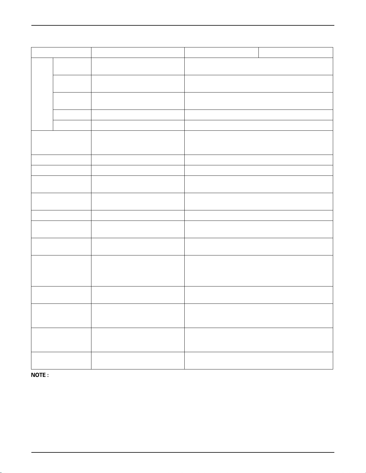
Implement Remarks B2301 B2601
Mid-mount
Rotary-cutter
(1 Blade)
Mower
Rotary tiller
Bot tom plow Max . siz e c m (in .) 36 (1 4) x 1
Dis c pl ow Max. size cm (in. ) 56 ( 22) x 1
Cul tiva tor M ax. si ze cm ( in.)
Disc harrow
Sprayer Max. tank capacity L (U.S.gals.) 190 (50)
Front blade
Rear-mount
(2 or 3 Blade)
Flail-mower Max. cutting width cm (in.) 122 (48)
Sickle bar Max. cutting width cm (in.) 152 (60)
Max . cut ting w idth cm ( in.)
Ma x. weigh t kg (lbs.)
Max . cut ting w idth cm ( in.)
Ma x. weigh t kg (lbs.)
Max . cut ting w idth cm ( in.)
Ma x. weigh t kg (lbs.)
Max.tilling width cm (in.)
Ma x. weigh t kg (lbs.)
Slip clutch
Ma x. harro win g width cm (in.)
Ma x. weigh t kg (lbs.)
Max . cut ting w idth cm ( in.)
Sub frame
152 (60)
140 (300)
122 (48)
204 (450)
152 (60)
227 (500)
127 (50)
213 (470)
Necessary
137 (54)
1 Row
152 (60)
190 (420)
152 (60)
Necessary
Rear blade
Front loader
Box blade
Back hoe
Snow blower
Trailer
A Implement size may vary depending on soil operating conditions.
Max . cut ting w idth cm ( in.)
Ma x. weigh t kg (lbs.)
Max. lifting capacity kg (lbs.)
(Bucket center)
Max . wid th cm ( in.)
Sub frame
Max . cut ting w idth cm ( in.)
Ma x. weigh t kg (lbs.)
Max. digging depth cm (in.)
Ma x. weigh t kg (lbs.)
Sub frame
Max. digging depth cm (in.)
Ma x. weigh t kg (lbs.)
Sub frame
Max. load capacity kg (lbs.)
Max. drawbar load kg (lbs.)
152 (60)
160 (350)
360 (794)
127 (50)
Necessary
137 (54)
227 (500)
198 (78)
320 (705)
Necessary
152 (60)
200(450)
Necessary
1000 (2200)
300 (660)
Page 25
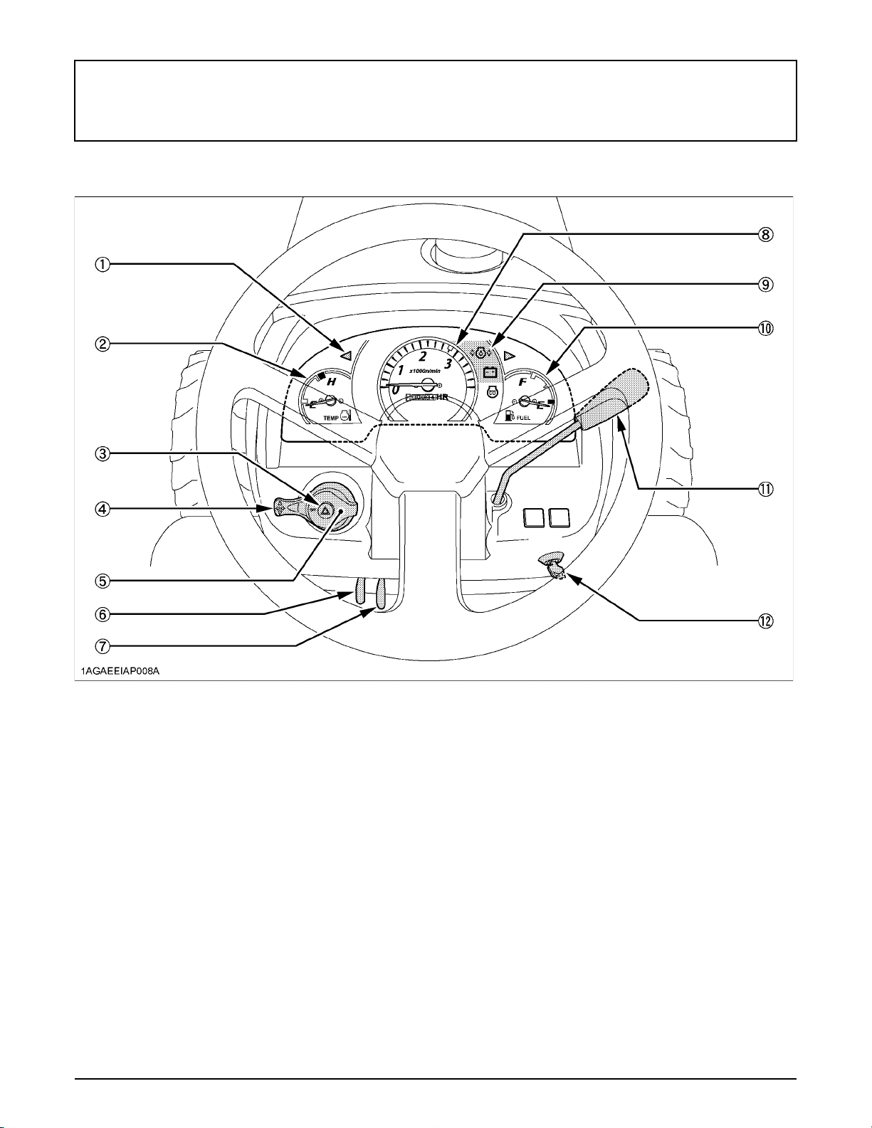
7INSTRUMENT PANEL AND CONTROLS
INSTRUMENT PANEL AND CONTROLS
B Instrument Panel, Switches and Hand Controls
ILLUSTRATED CONTENTS
(1) Turn signal / Hazard light indicator................ 20
(2) Coolant temperature gauge.......................... 26
(3) Hazard light switch........................................ 20
(4) Turn signal light switch.................................. 20
(5) Head light switch........................................... 20
(6) Parking brake lever....................................... 27
(7) Speed set lever............................................. 24
(8) Hourmeter / Tachometer............................... 27
(9) Easy Checker (TM)....................................... 25
(10) Fuel gauge.................................................. 26
(11) Hand throttle lever....................................... 23
(12) Key switch................................................... 10
Page 26
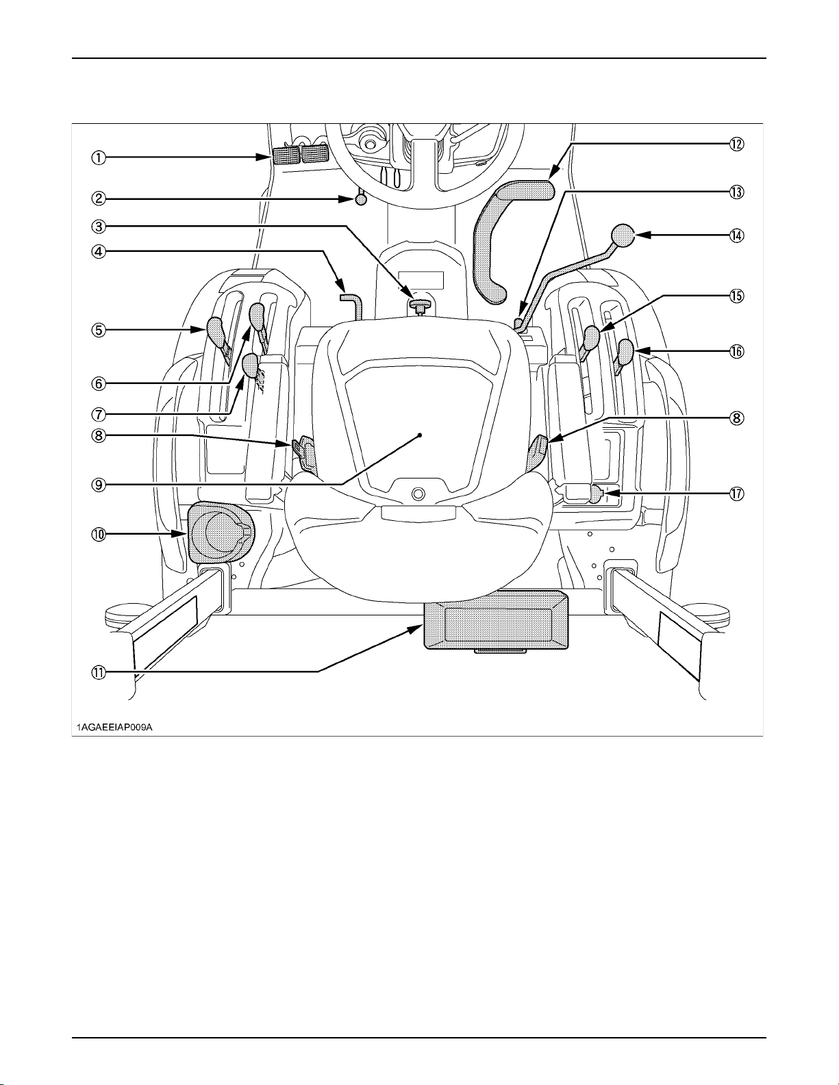
8 INSTRUMENT PANEL AND CONTROLS
B Foot and Hand Controls
ILLUSTRATED CONTENTS ILLUSTRATED CONTENTS
(1) Brake pedal.................................................... 21 (10) Cup holder.................................................. ---
(2) Steering wheel tilt pedal.................................. 19 (11) Tool-box...................................................... ---
(3) 3-Point hitch lowering speed knob.................. 35 (12) Speed control pedal.................................... 24
(4) Differential lock pedal..................................... 28 (13) Loader lock lever......................................... 37
(5) Range gear shift lever (L-M-H)........................ 22 (14) Loader control lever.................................... 37
(6) PTO clutch lever............................................. 31 (15) Front wheel drive lever................................ 23
(7) PTO select lever............................................. 30 (16) Position control lever................................... 35
(8) Seat belt......................................................... 19 (17) Electrical outlet............................................ 29
(9) Operator's seat............................................... 18
Page 27

PRE-OPERATION CHECK
DAILY CHECK
To prevent trouble from occurring, it is important to know
the condition of the tractor well. Check it before starting.
To avoid personal injury or death:
A Be sure to check and service the tractor on a
level surface with the engine shut off and the
parking brake "ON" and implement lowered to
the ground.
Check item
- Walk around inspection
- Check engine oil level
- Check transmission oil level
- Check coolant level
- Clean grill and radiator screen
- Check air cleaner evacuator valve
(When used in a dusty place)
- Check brake pedal
- Check indicators, gauges and meter
- Check lights
- Check wire harness
- Check Seat belt and ROPS
- Check movable parts
- Refuel
(See "DAILY CHECK" in "PERIODIC SERVICE"
section.)
- Care of danger, warning and caution labels
(See "DANGER, WARNING AND CAUTION LABELS"
in "SAFE OPERATION" section.)
9PRE-OPERATION CHECK
Page 28
10 OPERATING THE ENGINE
OPERATING THE ENGINE
A It is recommended that the operator practice engaging
To avoid personal injury or death:
A Read "Safe Operation" in the front of this manual.
A Read the danger, warning and caution labels
located on the tractor.
A To avoid the danger of exhaust fume poisoning,
do not operate the engine in a closed building
without proper ventilation.
A Never start engine while standing on ground. Start
engine only from operator's seat.
A Make it a rule to set all shift levers to the
"NEUTRAL" positions and to place the PTO lever
in "OFF" position before starting the engine.
A Do not use starting fluid or ether.
A To protect the battery and the starter, make sure that
the starter is not continuously turned for more than 30
seconds.
and disengaging the parking brake on a flat surface
without the engine running before operating the tractor
for the first time.
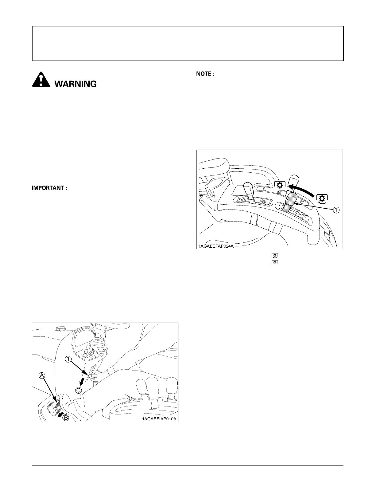
2. Place the PTO clutch lever in the
"OFF" position.
STARTING THE ENGINE
1. Make sure the parking brake is set.
1. To set the parking brake:
(1) Interlock the brake pedals.
(2) Depress the brake pedals.
(3) Latch the brake pedals with the parking brake
lever.
2. To release the parking brake, depress the brake
pedals again.
(1) PTO clutch lever "ON" "ENGAGE"
"OFF" "DISENGAGE"
(1) Parking brake lever (A) Interlock the brake pedals
(B) "DEPRESS"
(C) "PULL DOWN"
Page 29
11OPERATING THE ENGINE
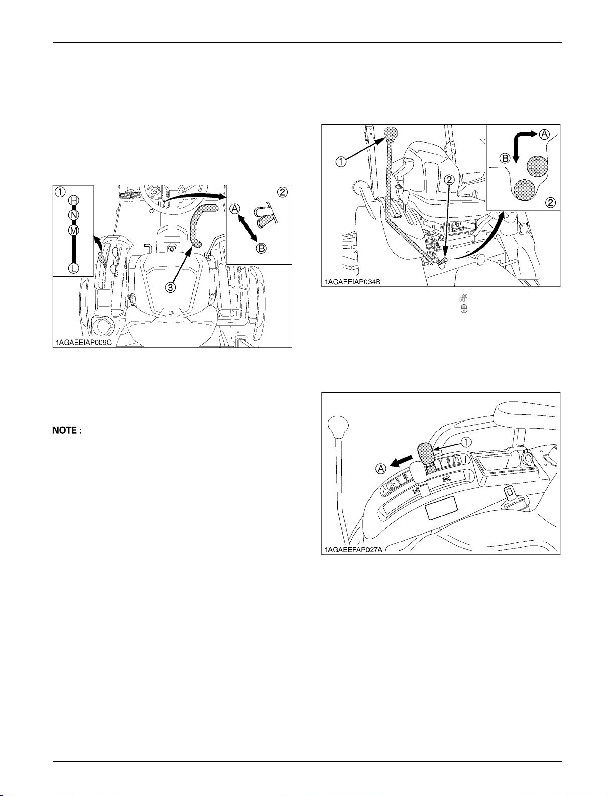
3. Place the speed set lever in "OFF"
position.
Place the speed control pedal in the
"NEUTRAL" position.
Place the range gear shift lever (L-M-H)
in the "NEUTRAL" position.
(1) Range gear shift lever (L-M-H)
(2) Speed set lever
(3) Speed control pedal
(A) "OFF"
(B) "ON"
(H) "HIGH"
(M) "MIDDLE"
(L) "LOW"
(N) "NEUTRAL POSITION"
4. Lock the loader control lever in the
"LOCK" position.
(1) Loader control lever
(2) Lock lever
(A) "UNLOCK"
(B) "LOCK"
5. Place the position control lever in the
"LOWEST" position.
A Depress the both brake pedals together, doing so the
speed set lever automatically returns to the off
position.
A By removing your foot from the speed control pedal, it
will allow the pedal to automatically return to the
neutral position.
(1) Position control lever (A) "DOWN"
Page 30
OPERATING THE ENGINE12
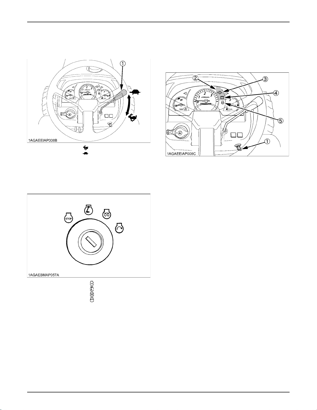
6. Set the throttle lever to about 1/2 way.
(1) Hand throttle lever "INCREASE"
"DECREASE"
7. Insert the key into the key switch and
turn it "ON".
C Check Easy Checker (TM) lamps:
When the key is turned "ON", lamps (3) (4) should come
on. If trouble should occur at any location while the engine
is running, the indicator lamp corresponding to problem
will turn "ON".
(1) Key switch
(2) Easy checker(TM)
(3) Engine oil pressure warning indicator
(4) Electrical charge warning indicator
(5) Glow plug indicator
"OFF"
"ON"
"PREHEAT"
"START"
Page 31
13OPERATING THE ENGINE
8. Turn the key to "PREHEAT" position
and hold it for about 2 to 3 seconds.
For the appropriate preheating time, refer to the table
below:
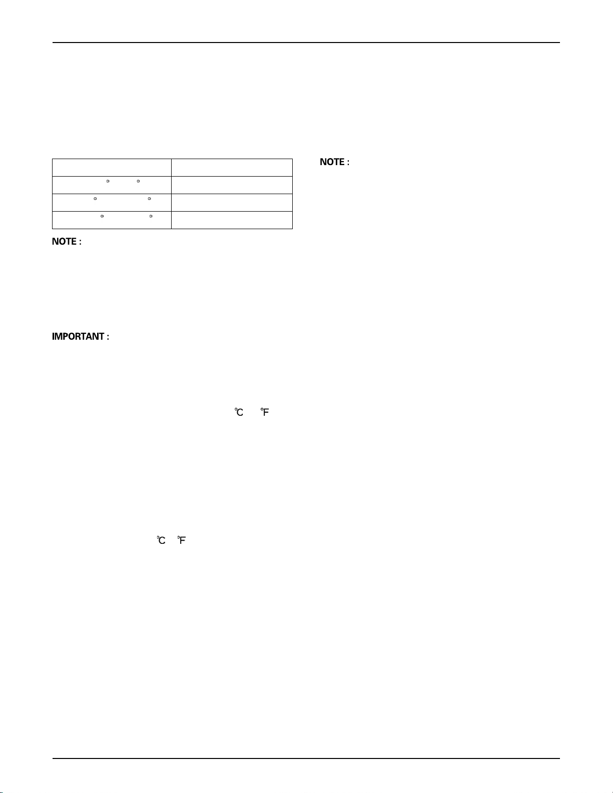
Temperature Preheating Time
Over 0 C (32 F) 2 to 3 sec.
0 to -5 C (32 to 23 F) 5 sec.
-5 to -15 C (23 to 5 F) 10 sec.
A Glow plug indicator (5) comes on while engine is being
preheated.
9. Turn the key to "START" position and
release when the engine starts.
A Because of the safety devices, the engine will not start
except when the PTO clutch lever is placed in the
"OFF" position and speed control pedal is placed in the
"NEUTRAL" position.
STOPPING THE ENGINE
1. After slowing the engine to idle, turn the
key to "OFF".
2. Remove the key.
A If key does not stop the engine, consult your local
KUBOTA Dealer.
C Cold Weather Starting
When the ambient temperature is below -5 (23 ) and
the engine is very cold. If the engine fails to start, turn off
the key for 30 seconds. Then repeat steps 8 and 9. To
protect the battery and the starter, make sure that the
starter is not continuously turned for more than 10
seconds.
BBlock Heater (Option)
A block heater is available as an option from your dealer.
It will assist you in starting your tractor when the ambient
temperature is below -15 (5 ).
10. Check to see that all the lamps on the
Easy Checker (TM) are "OFF".
If any lamps stays on, immediately stop the engine and
determine the cause.
Page 32
OPERATING THE ENGINE14
WARMING UP
To avoid personal injury or death:
A Be sure to set the parking brake during warm-
up.
A Be sure to set all shift levers to the "NEUTRAL"
positions and to place the PTO clutch lever in
the "OFF" position during warm-up.
For 5 minutes after engine start-up, allow the engine to
warm up without applying any load, this is to allow oil to
reach every engine part. If load should be applied to the
engine without this warm-up period, trouble such as
seizure, breakage or premature wear may develop.
BWarm-up Transmission Oil at Low
Ambient Temperatures
Hydraulic oil serves as transmission fluid. In cold weather,
the oil will be cold, which will increase oil viscosity. This
can cause delayed oil circulation or abnormally low
hydraulic pressure for some time after engine start-up.
This in turn can result in trouble in the hydraulic system.
To prevent the above, observe the following instructions:
Warm up the engine at about 50% of rated rpm according
to the table below:
Ambient temperature Warm-up time requirement
Above 0 C (32 F) At least 5 minutes
0 to -10 C (32 to 14 F) 5 to 10 minutes
JUMP STARTING
To avoid personal injury or death:
A Battery gases can explode. Keep cigarettes,
sparks, and flames away from battery.
A If tractor battery is frozen, do not jump start
engine.
A Do not connect the other end of the negative
(-) jumper cable to the negative (-) terminal of
the tractor battery.
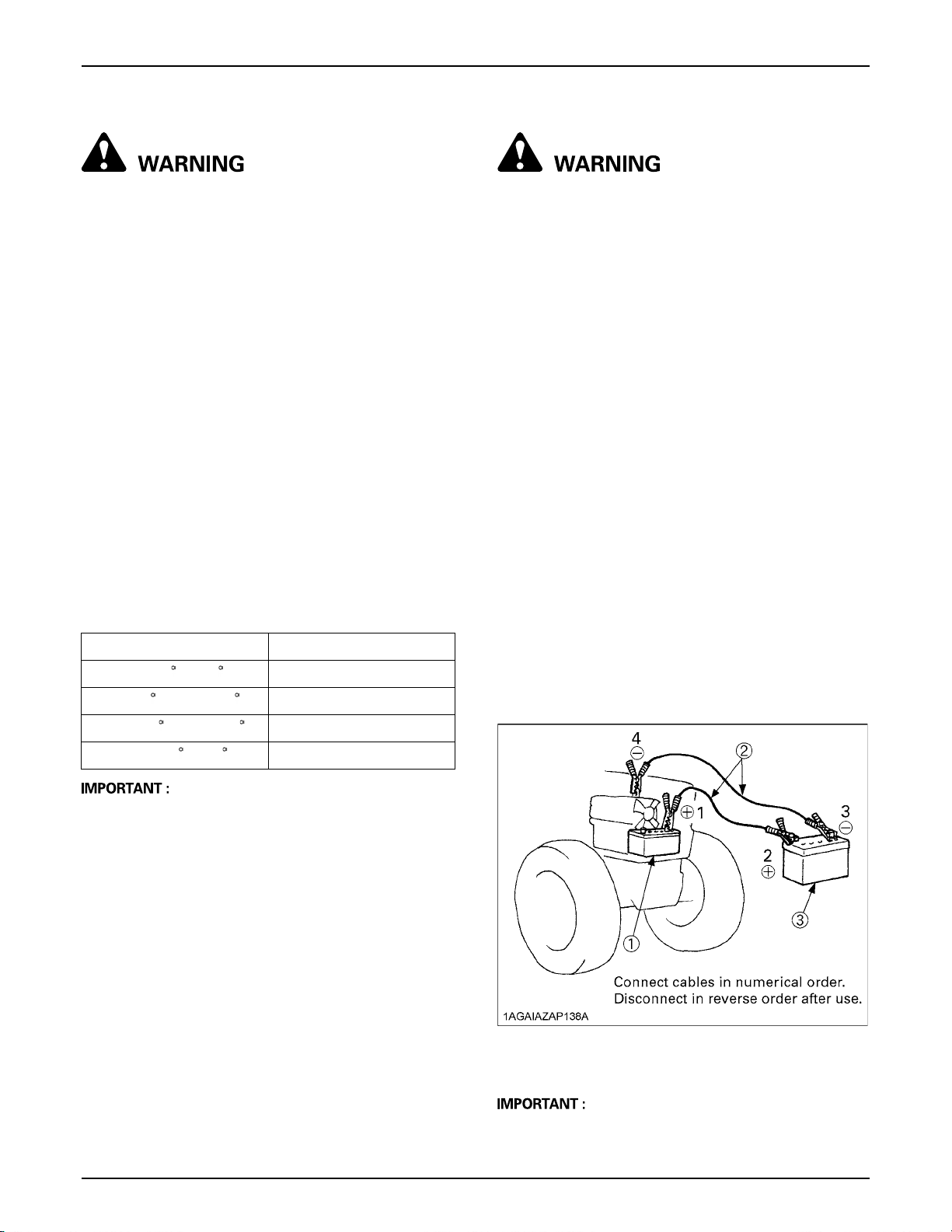
When jump starting the engine, follow the instructions
below to safely start the engine.
1. Bring the helper vehicle with a battery of the same
voltage as disabled tractor within easy cable reach.
"THE VEHICLES MUST NOT TOUCH".
2. Engage the parking brakes of both vehicles and put
the shift levers in neutral. Shut both engines off.
3. Wear eye protection and rubber gloves.
4. Attach the red clamp to the positive (red, (+) or pos.)
terminal of the dead battery and clamp the other end
of the same cable to the positive (red, (+) or pos.)
terminal of the helper battery.
5. Clamp the other cable to the negative (black, (-) or
neg.) terminal of the helper battery.
6. Clamp the other end to the engine block or frame of
the disabled tractor as far from the dead battery as
possible.
7. Start the helper vehicle and let its engine run for a few
moments. Start the disabled tractor.
8. Disconnect the jumper cables in the exact reverse
order of attachment. (Steps 6, 5 and 4)
-10 to -20 C (14 to -4 F) 10 to 15 minutes
Below -20 C (-4 F) More than 15 minutes
A Do not operate the tractor under full load condition until
it is sufficiently warmed up.
(1) Dead battery
(2) Jumper cables
(3) Helper battery
A This machine has a 12volt negative (-) ground starting
system.
Page 33

A Use only same voltage for jump starting.
A Use of a higher voltage source on tractors electrical
system could result in severe damage to tractor's
electrical system.
Use only matching voltage source when "Jump
starting" a low or dead battery condition.
15OPERATING THE ENGINE
Page 34
16 OPERATING THE TRACTOR
OPERATING THE TRACTOR
OPERATING NEW TRACTOR
How a new tractor is handled and maintained determines
the life of the tractor.
A new tractor just off the factory production line has been,
of course, tested, but the various parts are not
accustomed to each other, so care should be taken to
operate the tractor for the first 50 hours at a slower speed
and avoid excessive work or operation until the various
parts become "broken-in." The manner in which the
tractor is handled during the "breaking-in." period greatly
affects the life of your tractor. Therefore, to obtain the
maximum performance and the longest life of the tractor,
it is very important to properly break-in your tractor. In
handling a new tractor, the following precautions should
be observed.
BDo not Operate the Tractor at Full Speed
for the First 50 Hours
A Do not start quickly nor apply the brakes suddenly.
A In winter, operate the tractor after fully warming up the
engine.
A Do not run the engine at speeds faster than
necessary.
A On rough roads, slow down to suitable speeds.
Do not operate the tractor at fast speed.
The above precautions are not limited only to new
tractors, but to all tractors. But it should be especially
observed in the case of new tractors.
OPERATING FOLDABLE ROPS
To avoid personal injury or death:
A When raising or folding the ROPS, apply
parking brake, stop the engine and remove the
key.
Always perform function from a stable position
at the rear of tractor.
A Fold the ROPS down only when absolutely
necessary and fold it up and lock it again as
soon as possible.
A Before proceeding to fold ROPS, check for any
possible interference with installed
implements and attachments.
If interference occurs, contact your KUBOTA
Dealer.
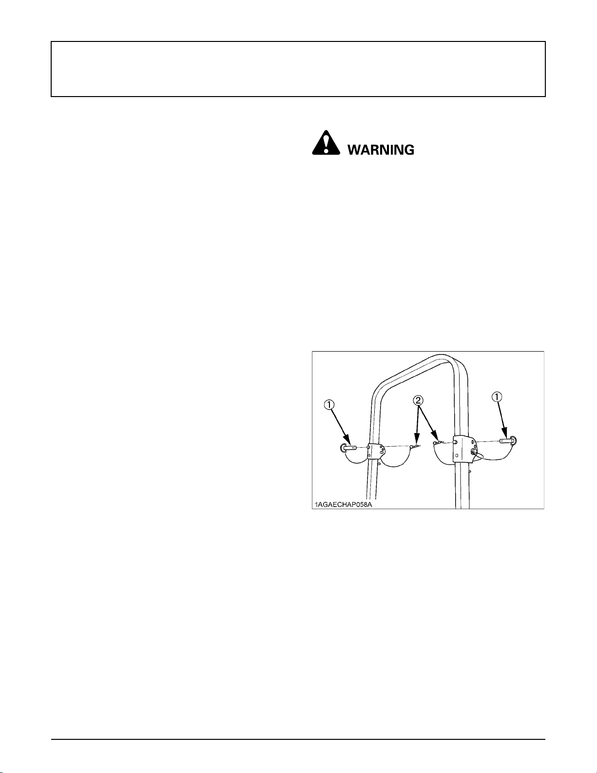
BTo Fold the ROPS
1. Remove both set bolts, maintain a hold on the ROPS.
BChanging Lubricating Oil for New Tractors
The lubricating oil is especially important in the case of a
new tractor. The various parts are not "broken-in" and are
not accustomed to each other; small metal grit may
develop during the operation of the tractor; and this may
wear out or damage the parts. Therefore, care should be
taken to change the lubricating oil a little earlier than
would ordinarily be required.
For further details of change interval hours, see
"MAINTENANCE" section.
(1) Set bolt
(2) Hair pin
BOARDING AND LEAVING THE TRACTOR
1. Never try to get on or off a moving tractor or jump off
the tractor to exit.
2. Face the tractor when getting into or out of the tractor.
Do not use the controls as hand holds to prevent
inadvertent machine movements.
3. Always keep steps and floor clean to avoid slippery
conditions.
Page 35
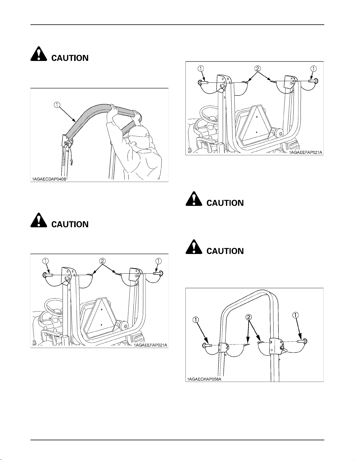
2. Fold the ROPS.
To avoid personal injury:
A Hold the ROPS tightly with both hands and fold
the ROPS slowly and carefully.
(1) ROPS
17OPERATING THE TRACTOR
BTo Raise the ROPS to Upright Position
1. Remove both hair pins and set bolts.
(1) Set bolt
(2) Hair pin
2. Raise ROPS to the upright position, maintain a hold on
the ROPS.
3. Insert both set bolts and secure them with the hair
pins.
To avoid personal injury:
A Make sure that both set bolts are properly
installed and secured with the hair pins.
(1) Set bolt
(2) Hair pin
To avoid personal injury:
A Raise the ROPS slowly and carefully.
3. Insert both set bolts and secure them with the hair
pins.
To avoid personal injury:
A Make sure that both set bolts are properly
installed as soon as the ROPS is in the upright
position and secured with the hair pins.
(1) Set bolt
(2) Hair pin
Page 36
OPERATING THE TRACTOR18
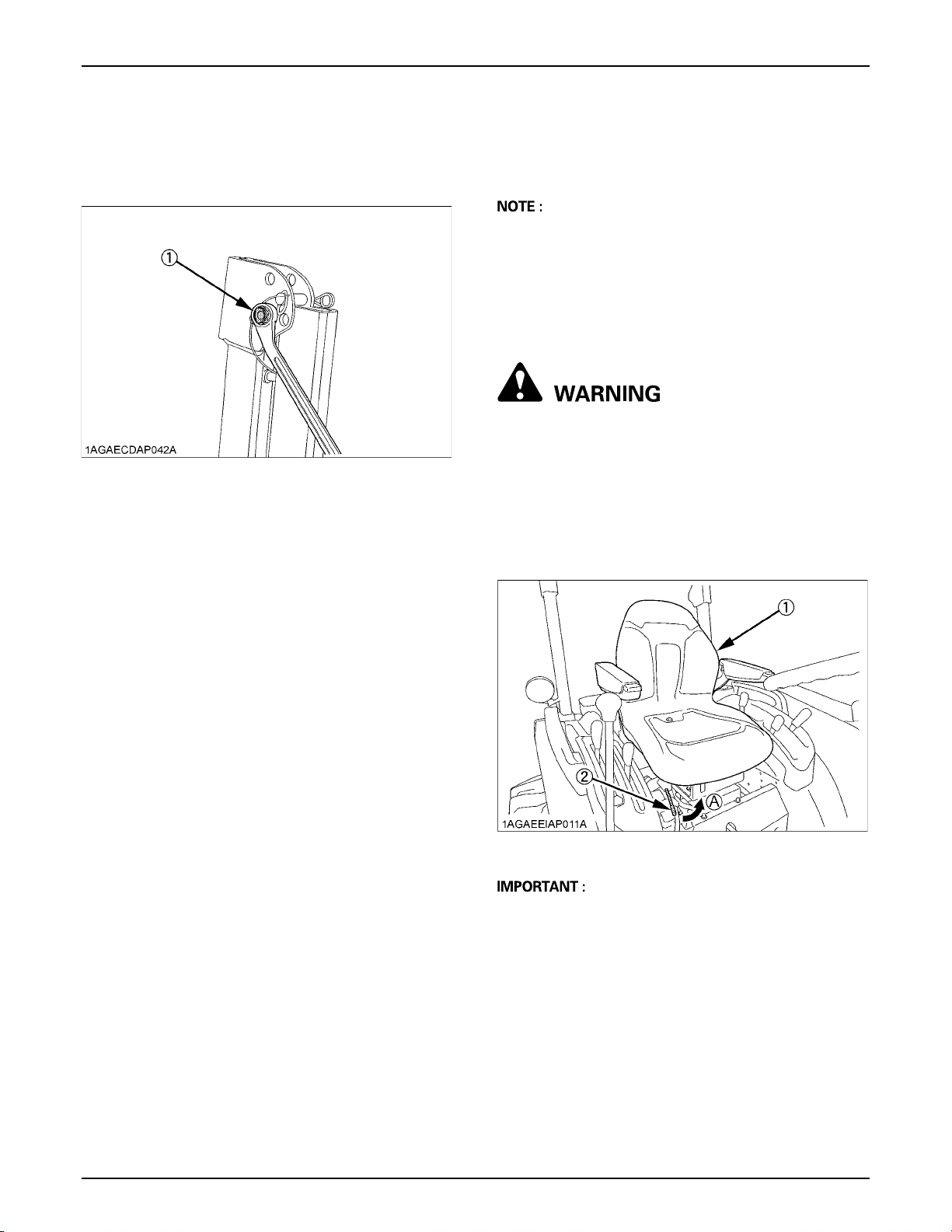
BAdjustment of Foldable ROPS
A Adjust free fall of the ROPS upper frame regularly.
A If you feel less friction in folding the ROPS, tighten the
nut (1) until you feel the right friction in the movement.
(1) Nut
STARTING
1. Adjusting the operator's position.
A The seat and suspension should be adjusted to
ensure that the controls are comfortably at hand for the
operator, ensuring that the operator maintains a good
posture and minimizes risks from whole body
vibration.
BOperator's Seat
To avoid personal injury or death:
A Make sure that the seat is completely secured
after each adjustment.
A Do not allow any person other than the driver to
ride on the tractor.
C Position adjustment
Pull in the position adjust lever and slide the seat
backward or forward, as required. The seat will lock in
position when the lever is released.
(1) Seat
(2) Position adjust lever
A After adjusting the operator's seat, be sure to check
that the seat is properly locked.
(A) "PULL IN"
Page 37
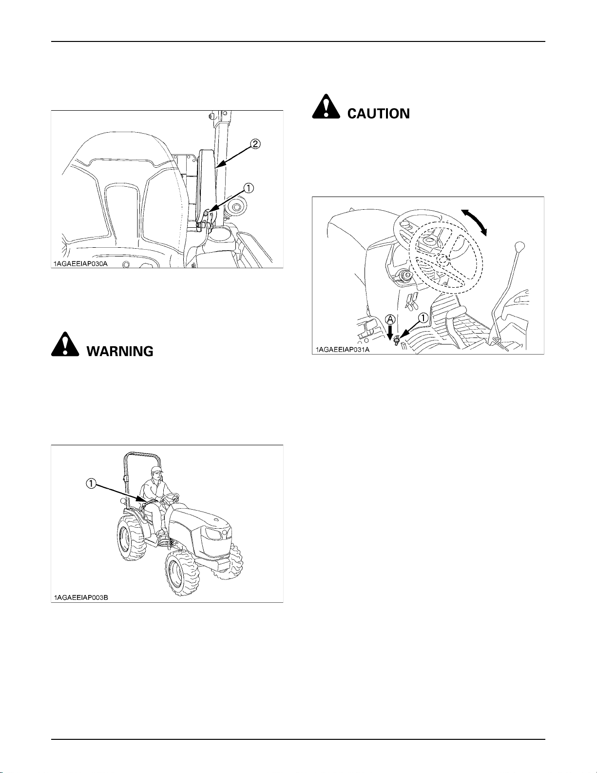
C Armrest angle adjustment
The armrest angle can be adjusted by the bolts (socket
size 7/16 inch).
(1) Bolt
(2) Armrest
19OPERATING THE TRACTOR
BTilt Steering Adjustment
To avoid personal injury:
A Do not adjust the steering wheel while the
tractor is in motion.
Press down the steering wheel pedal, to release the lock
so the steering wheel can be adjusted to one of three
desired positions.
BSeat Belt
To avoid personal injury or death:
A Always use the seat belt when the ROPS is
installed.
A Do not use the seat belt if a foldable ROPS is
down or there is no ROPS.
Adjust the seat belt for proper fit and connect to the
buckle. The seat belt is auto-locking retractable type.
(1) Steering wheel tilt pedal (A) "PRESS DOWN"
(1) Seat belt
Page 38
OPERATING THE TRACTOR20
2. Selecting light switch positions.
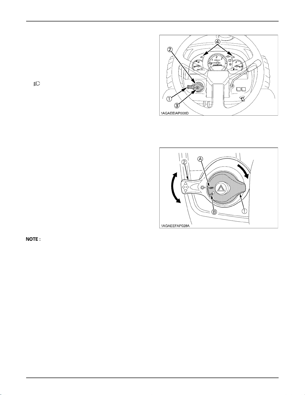
BHead Light / Turn Signal / Hazard Light
Switch
C Head Light Switch
(A) OFF....Head light OFF.
(B) .....Head light ON.
C Hazard Light
1. When hazard light switch is pushed, the hazard lights
flash, along with the L/H and R/H indicators on the
instrument panel.
2. Push hazard light switch again to turn off the hazard
lights.
C Turn Signal with Hazard Light Switch On
1. To indicate a right turn with the hazard lights already
flashing (hazard switch on), turn the turn signal switch
clockwise.
2. To indicate a left turn with the hazard lights already
flashing, turn the turn signal switch counterclockwise.
3. When the left or right turn signal is activated in
combination with the hazard lights, the indicated
turning light will flash and the other will stay on.
(1) Turn signal light switch
(2) Head light switch
(3) Hazard light switch
(4) Hazard / Turn signal indicator
C Turn Signal with Hazard Light Switch Off
1. To indicate a right turn without hazard lights (hazard
switch off), turn the turn signal switch clockwise.
2. To indicate a left turn without hazard lights, turn the
turn signal switch counterclockwise.
3. When the left or right turn signal is activated without
the hazard lights, the indicated turning light will flash
and the other will stay on.
A The hazard light switch is operative when the key
switch is in either the "ON" or "OFF" positions.
A The turn signal light switch is only operative when the
key switch is in the "ON" position.
A The indicator in the hazard light switch will light up
when the head light switch is turned on.
A Be sure to return the turn signal switch to center
position after turning.
(1) Head light switch
(2) Turn signal light switch
(A) "OFF"
(B) "ON"
Page 39
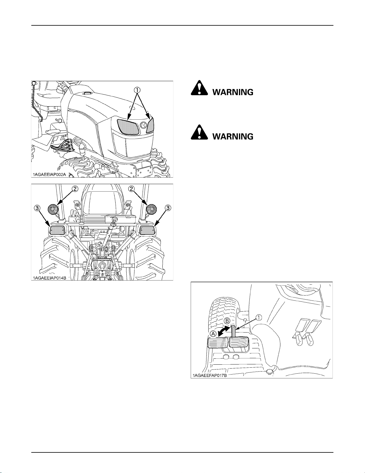
21OPERATING THE TRACTOR
BTractor Lights
(1) Head light
(2) Turn signal / Hazard light
(3) Tail light
3. Checking the brake pedal.
BBrake Pedals (Right and Left)
To avoid personal injury or death:
A Applying only one rear wheel brake at high
speeds could cause the tractor to swerve or
roll-over.
To avoid personal injury or death:
A An accident may occur if the tractor is
suddenly braked, such as by heavy towed
loads shifting forward or loss of control.
A The braking characteristics are different
between 2 and 4 wheel drive. Be aware of the
difference and use carefully.
A When driving on icy, wet or loose surfaces,
make sure the tractor is correctly ballasted to
avoid skidding and loss of steering control.
Operate at reduced speed.
1. Before operating the tractor on the road or before
applying the parking brake, be sure to interlock the
right and left pedals as illustrated below.
2. Use individual brakes to assist in making sharp turns
at slow speeds (Field Operation Only). Disengage the
brake pedal lock and depress only one brake pedal.
3. Be sure brake pedals have equal adjustment when
using locked together.
(1) Brake pedal lock (A) "LOCK"
(B) "RELEASE"
Page 40
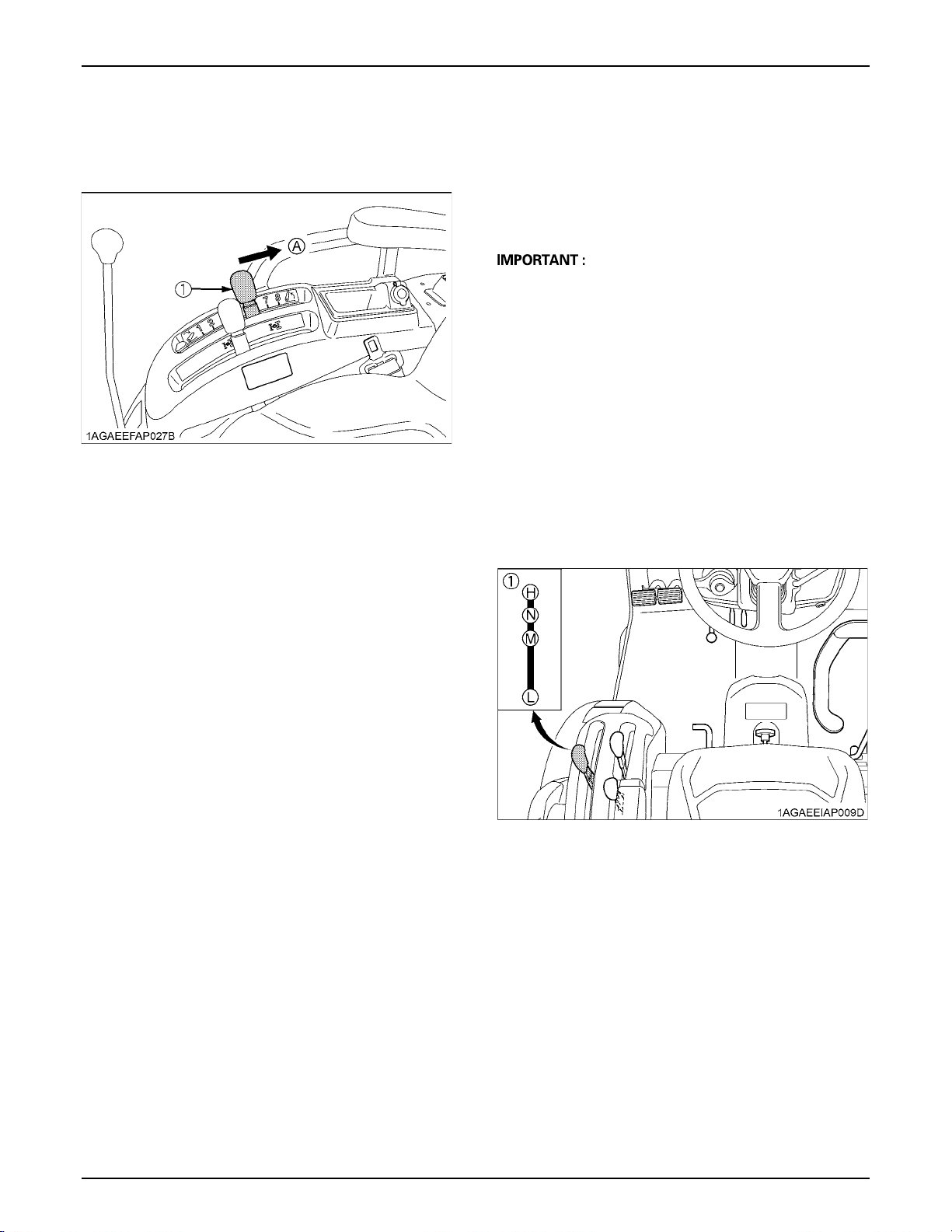
OPERATING THE TRACTOR22
4. Raise the implement.
(See "HYDRAULIC UNIT" section.)
(1) Position control lever (A) "UP"
5. Selecting the Travel Speed.
BRange Gear Shift Lever (L-M-H)
The range gear shift can only be shifted when tractor is
completely stopped.
Do not force the range gear shift lever.
A If it is difficult to shift the range gear shift lever into the
neutral position;
(1) Depress the brake pedal firmly for several
seconds.
(2) Without reducing the brake pedal force, shift the
range gear shift lever.
A If it is difficult to shift the range gear shift lever into "L",
"M" or "H" from neutral position;
(1) Slightly depress the speed control pedal to rotate
the gears inside of transmission.
(2) Release the speed control pedal to neutral
position.
(3) Shift the range gear shift lever.
A To avoid damage of transmission, stop tractor before
shifting between ranges.
(1) Range gear shift lever
(L-M-H)
(H) "HIGH"
(M) "MIDDLE"
(L) "LOW"
(N) "NEUTRAL POSITION"
Page 41
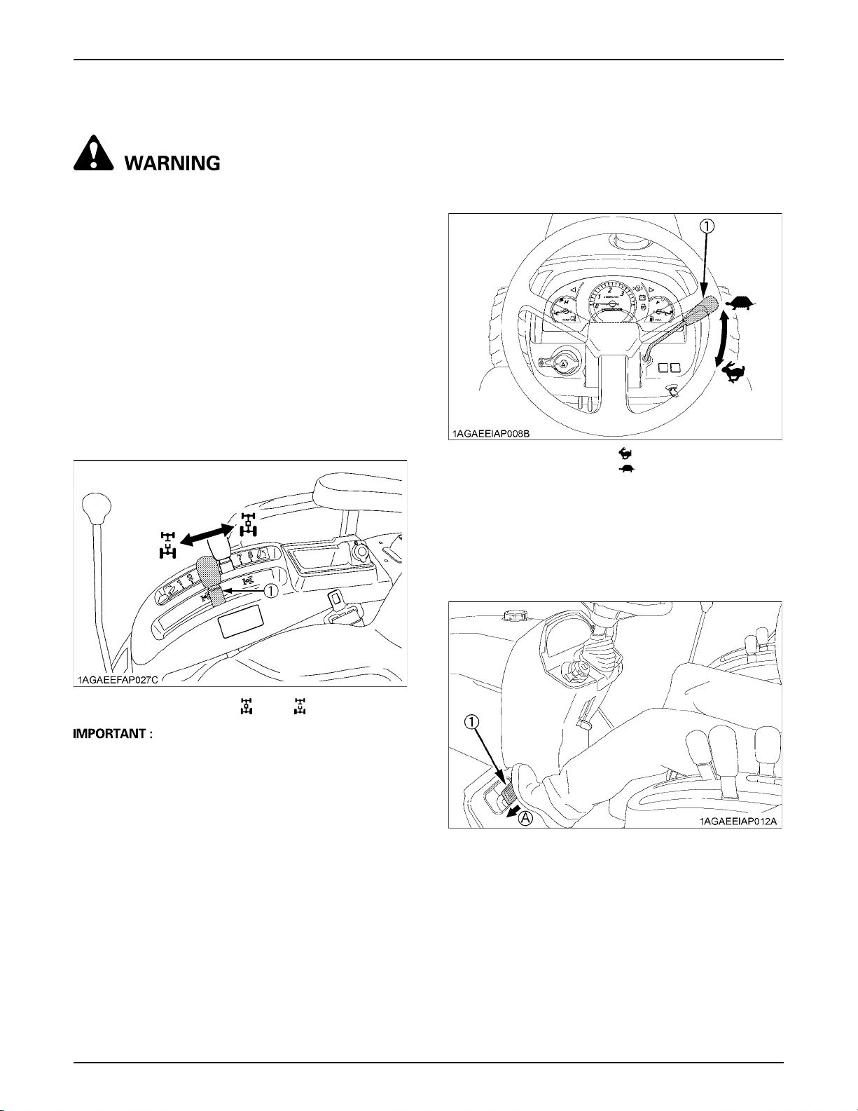
23OPERATING THE TRACTOR
BFront Wheel Drive Lever
To avoid personal injury or death:
A Do not engage the front wheel drive when
traveling at road speed.
A When driving on icy, wet or loose surfaces,
make sure the tractor is correctly ballasted to
avoid skidding and loss of steering control.
Operate at reduced speed and engage front
wheel drive.
A An accident may occur if the tractor is
suddenly braked, such as by heavy towed
loads shifting forward or loss of control.
A The braking characteristics are different
between 2 and 4-wheel drive. Be aware of the
difference and use carefully.
Use the lever to engage the front wheels with the tractor
stopped. Shift the lever to "ON" to engage the front wheel
drive.
6. Accelerate the Engine.
BHand Throttle Lever
Pulling the throttle lever back increases engine speed,
and pushing it forward decreases engine speed.
(1) Hand Throttle lever "INCREASE"
"DECREASE"
7. Unlock the Parking Brake.
(1) Front wheel drive lever "ON" "OFF"
A To avoid damage of transmission, when front wheel
drive lever is not smoothly shifted, slightly step forward
or rearward on speed control pedal.
A Tires will wear quickly if front wheel drive is engaged
on paved roads.
C Front wheel drive is effective for the following
jobs:
1. When greater pulling force is needed, such as working
in a wet field, when pulling a trailer, or when working
with a front-end loader.
2. When working in sandy soil.
3. When working on a hard soil where a rotary tiller might
push the tractor forward.
4. Additional braking at reduced speeds.
BParking Brake
To release the parking brake, depress the brake pedals
again.
(1) Brake pedals (A) "DEPRESS"
Page 42
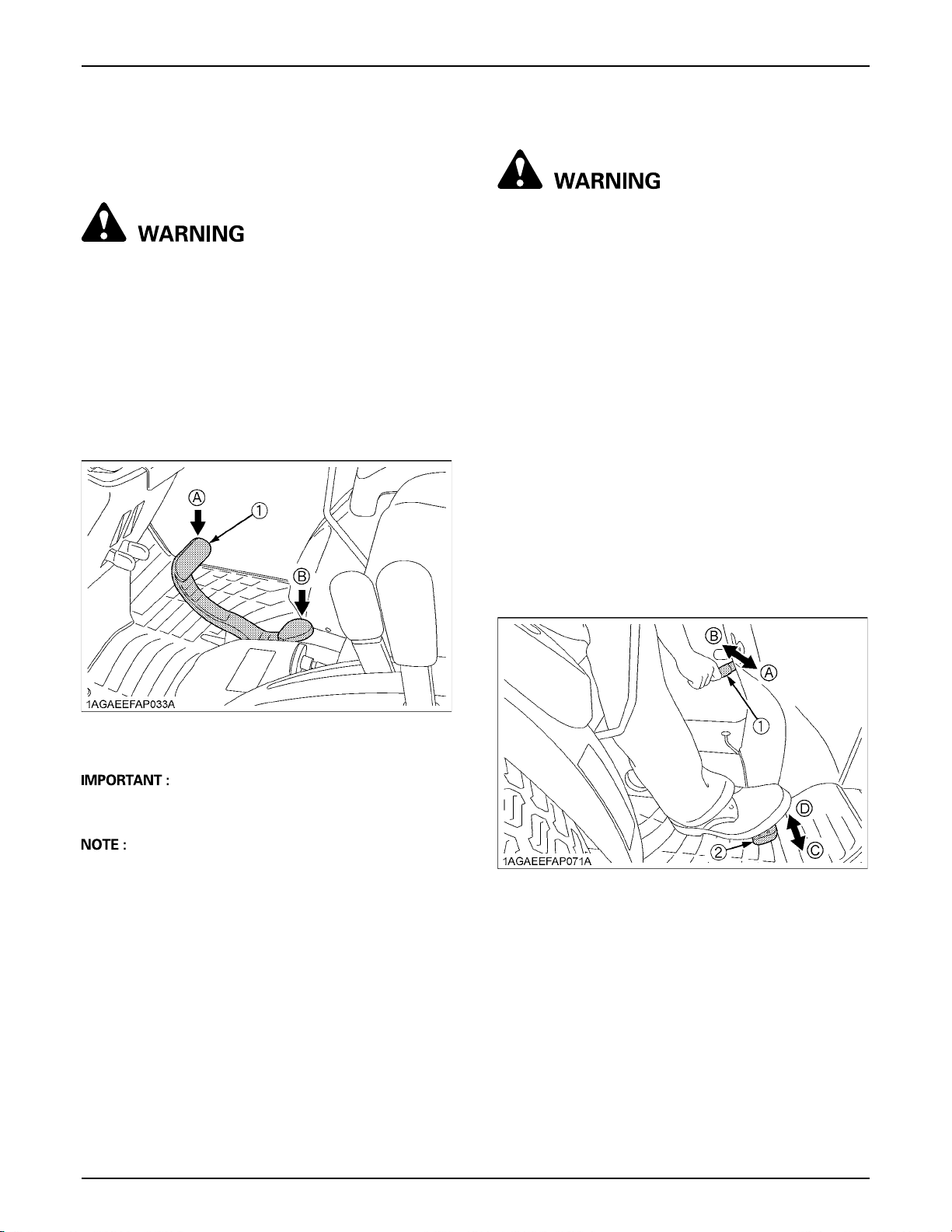
OPERATING THE TRACTOR24
8. Depress the Speed Control Pedal.
BSpeed Control Pedal
To avoid personal injury or death:
A Do not operate if the tractor moves on level
ground with the operators foot off of Speed
Control Pedal.
A Consult your local KUBOTA Dealer.
Forward Pedal
Depress the speed control pedal with the toe of your right
foot to move forward.
Reverse Pedal
Depress the speed control pedal with the heel of your right
foot to move backward.
BSpeed Set Device
To avoid personal injury or death:
A Pull the speed set lever completely to the up
position before starting the engine.
A Do not use the speed set device when driving
on the road.
A Be sure to connect both the left and the right
brakes to release the speed set device. The
speed set device won't be released with
singlebrake activation.
The Speed Set Device is designed for tractor operating
efficiency and operator comfort. This device will provide a
constant forward operating speed by mechanically
holding the speed control pedal at a selected position.
C To engage Speed Set Device
1. Accelerate speed to desired level using Speed Control
Pedal, and push the speed set lever down to the "ON"
position.
2. Release Speed Control Pedal and desired speed will
be maintained.
(1) Speed control pedal (A) "FORWARD"
(B) "REVERSE"
A To prevent serious damage to the HST, do not adjust
the stopper bolts.
A When you stand up from the seat with the speed
control pedal stepped on or the speed set device
engaged (ON), the engine will stop regardless of
whether the machine is moving or not. This is because
the tractor is equipped with Operator Presence Control
system (OPC).
C To disengage Speed Set Device
A Depress both brake pedals.
(1) Speed set lever
(2) Speed control pedal
(A) "ON"
(B) "OFF"
(C) "Increase"
(D) "Decrease"
Page 43
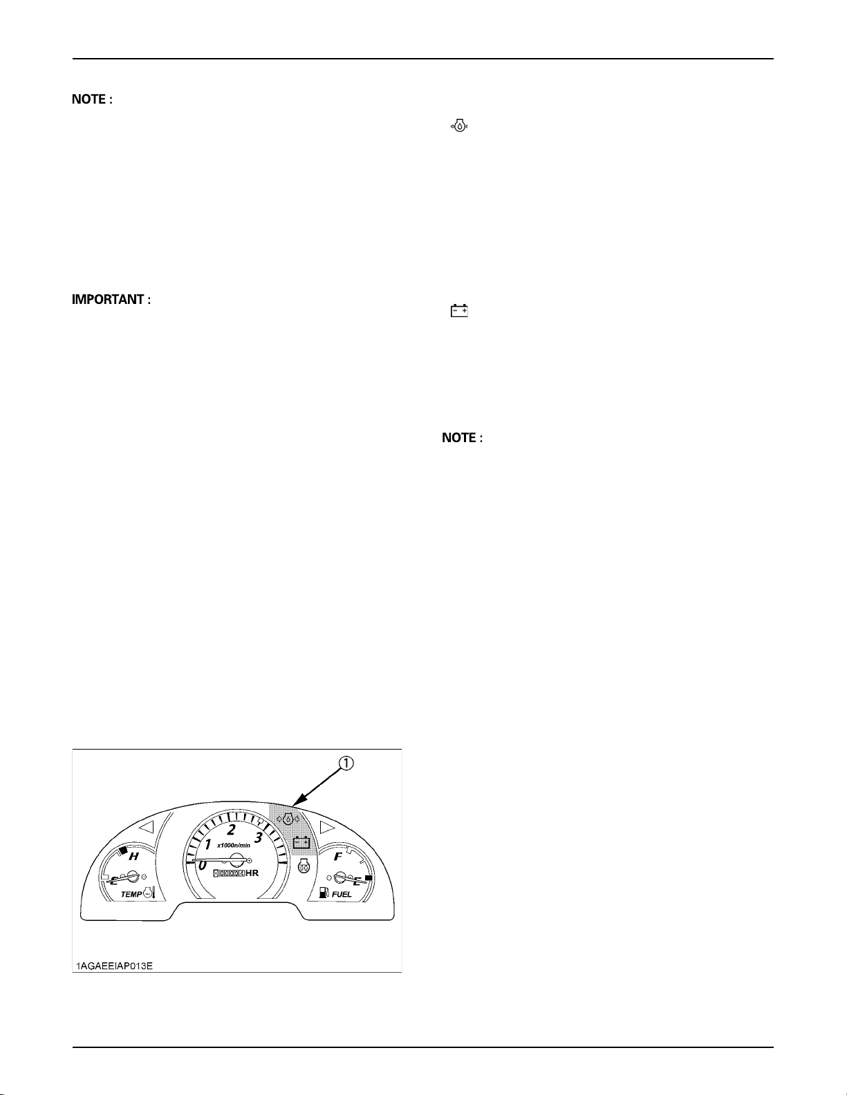
25OPERATING THE TRACTOR
A If you step on the pedal on the forward acceleration
side, the speed set device will disengage.
A The speed set device does not disengage when the
individual right or left brake is applied.
A Speed set device will not operate in reverse.
A When you stand up from the seat with the speed
control pedal stepped on or the speed set device
engaged (ON), the engine will stop regardless of
whether the machine is moving or not. This is because
the tractor is equipped with Operator Presence Control
system (OPC).
A To prevent the damage of speed set device, do not
depress the reverse pedal when the speed set device
is engaged.
STOPPING
BStopping
1. Slow the engine down.
2. Step on the brake pedal.
3. After the tractor has stopped, disengage the PTO,
lower the implement to the ground, shift the
transmission to neutral and set the parking brake.
Engine oil pressure
If the oil pressure in the engine goes below the
prescribed level, the warning lamp in the Easy
Checker (TM) will come on.
If this should happen during operation, and it does
not go off when the engine is accelerated to more
than 1000 rpm, check level of engine oil.
(See "Checking Engine Oil Level" in "DAILY
CHECK" in "PERIODIC SERVICE" section.)
Electrical charge
If the alternator is not charging the battery, the
warning lamp in the Easy Checker (TM) will come
on.
If this should happen during operation, check the
electrical charging system or consult your local
KUBOTA Dealer.
A For checking and servicing of your tractor, consult
your local KUBOTA Dealer for instructions.
CHECK DURING DRIVING
BImmediately Stop the Engine if:
A The engine suddenly slows down or accelerates.
A Unusual noises suddenly are heard.
A Exhaust fumes suddenly become very dark.
BEasy Checker (TM)
If the warning lamps of the Easy Checker (TM) come on
during operation, immediately stop the engine, and find
the cause as shown below.
Never operate the tractor while Easy Checker (TM) lamp
is on.
(1) Easy Checker (TM)
Page 44
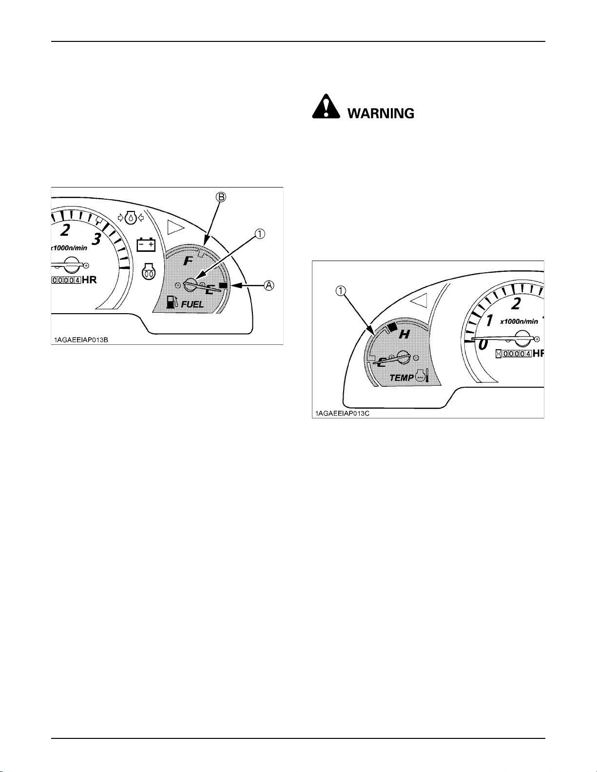
OPERATING THE TRACTOR26
BFuel Gauge
When the key switch is on, the fuel gauge indicates the
fuel level.
Be careful not to empty the fuel tank. Otherwise air may
enter the fuel system.
Should this happen, the system should be bled. (See
"Bleeding Fuel System" in "SERVICE AS REQUIRED" in
"PERIODIC SERVICE" section.)
(1) Fuel gauge (A) "EMPTY"
(B) "FULL"
BCoolant Temperature Gauge
To avoid personal injury or death:
A Do not remove radiator cap until coolant
temperature is well below its boiling point.
Then loosen the cap slightly to relieve any
pressure before removing the cap completely.
1. With the key switch "ON", this gauge indicates the
temperature of the coolant. "C" for "cold" and "H" for
"hot".
2. If the indicator reaches the "H" position (red zone),
engine coolant is overheated. Check the tractor by
referring to "TROUBLESHOOTING" section.
(1) Coolant temperature gauge
Page 45
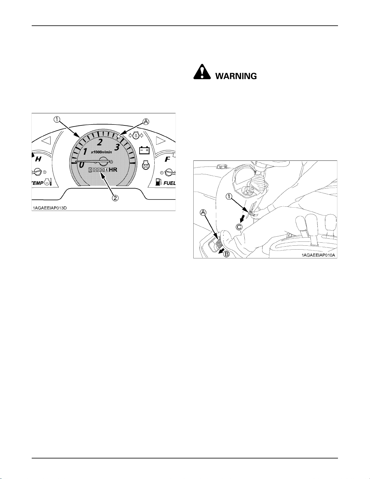
27OPERATING THE TRACTOR
BHourmeter / Tachometer
This meter gives readings for engine speed, PTO shaft
speed and the hours the tractor has been operated.
1. The tachometer indicates the engine speed and the
540 PTO shaft speed location on the dial.
2. The hourmeter indicates in 5 digits the hours the
tractor has been used; the last digit indicates 1/10 of
an hour.
(1) Engine revolution
(2) Hours used
(A) PTO: 540 rpm
PARKING
BParking
To avoid personal injury or death:
A Always set the parking brake, stop the engine
and remove the key before leaving the tractor
seat.
1. When parking, be sure to set the parking brake.
To set the parking brake;
(1) Interlock the brake pedals.
(2) Depress the brake pedals.
(3) Latch the brake pedals with the parking brake
lever.
(1) Parking brake lever (A) Interlock the brake pedals
(B) "DEPRESS"
(C) "PULL DOWN"
2. Before getting off the tractor, disengage the PTO,
lower all implements to the ground, place all control
levers in their neutral positions, set the parking brake,
stop the engine and remove the key.
3. If it is necessary to park on an incline, be sure to chock
the wheels to prevent accidental rolling of the
machine.
Page 46
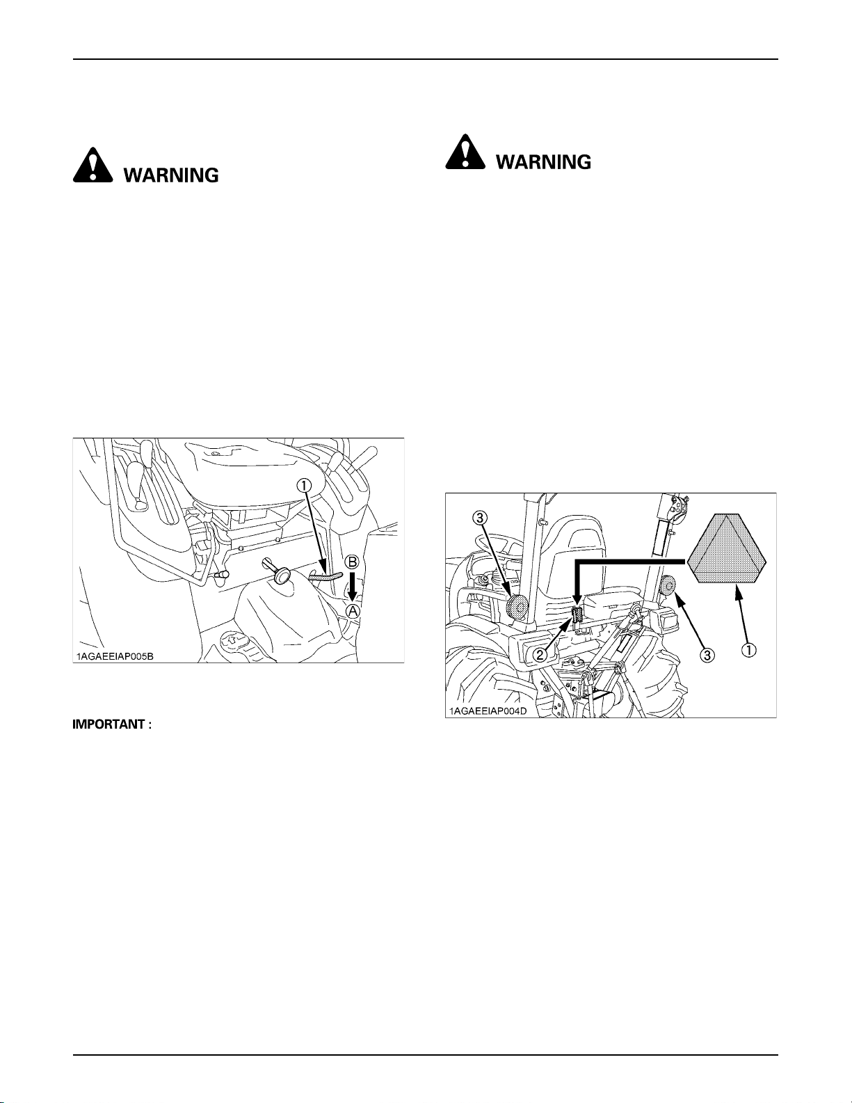
OPERATING THE TRACTOR28
OPERATING TECHNIQUES
BDifferential Lock
To avoid personal injury or death due to loss of
steering control:
A Do not operate the tractor at high speed with
differential lock engaged.
A Do not attempt to turn with the differential lock
engaged.
A Be sure to release the differential lock before
making a turn in field conditions.
If one of the rear wheels should slip, step on the
differential lock pedal. Both wheels will turn together, then
reduce slippage.
Differential lock is maintained only while the pedal is
depressed.
BOperating the Tractor on a Road
To avoid personal injury or death:
A To help assure straight line stops when driving
at transport speeds, lock the brake pedals
together. Uneven braking at road speeds could
cause the tractor to roll-over.
A When traveling on road with 3-point hitch
mounted implement attached, be sure to have
sufficient front weight on the tractor to
maintain steering ability. (See "BALLAST"
section.)
A Towed equipment (without brake) must not
exceed 1.5 times the tractor weight when
traveling on roads or at high speeds.
Be sure SMV emblem and hazard light are clean and
visible. If towed or rear-mounted equipment obstructs
these safety devices, install SMV emblem and hazard
light on equipment.
Consult your local KUBOTA dealer for further detail.
(1) Differential lock pedal (A) Press to "ENGAGE"
(B) Release to "DISENGAGE"
A When using the differential lock, always slow the
engine down.
A To prevent damage to power train, do not engage
differential lock when one wheel is spinning and the
other is completely stopped.
A If the differential lock cannot be released in the above
manner, step lightly on the brake pedals alternately.
(1) SMV emblem
(2) Bracket
(3) Hazard light
Page 47
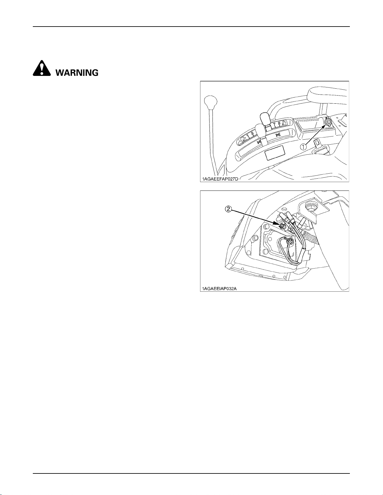
29OPERATING THE TRACTOR
BOperating on Slopes or Rough Terrain
To avoid personal injury or death:
A Always back up when going up a steep slope.
Driving forward could cause the tractor to tip
over backward. Stay off hills and slopes too
steep for safe operation.
A Avoid changing gears when climbing or
descending a slope.
A If operating on a slope, never disengage shift
levers to neutral. Doing so could cause loss of
control.
A Do not drive the tractor close to the edges of
ditches or banks which may collapse under the
weight of the tractor. Especially when the
ground is loose or wet.
1. Slow down for slopes, rough ground, and sharp turns,
especially when transporting heavy, rear mounted
equipment.
2. Before descending a slope, be sure that the range
lever is in the low so that speed can be controlled
without using brakes.
BElectrical Outlet
An electrical outlet is supplied for use with implement and
electrical equipment .
BTransport the Tractor Safely
1. The tractor, if damaged, must be carried on a truck.
Secure the tractor tightly with ropes.
2. Follow the instruction below when towing the tractor:
Otherwise, the tractor’s powertrain may get damaged.
A Set the all shift levers to "NEUTRAL" position.
A If possible, start engine and select 2WD, if creep
speed is fitted ensure that it is disengaged.
A Tow the tractor using its front hitch or drawbar.
A Never tow faster than "10 km/h (6.2 mph)".
BDirections for Use of Power Steering
1. Power steering is activated only while the engine is
running. While the engine is stopped, the tractor
functions in the same manner as tractors without
power steering.
2. When the steering wheel is turned all the way to the
stop, the relief valve is activated. Do not hold the
steering wheel in this position for a long period of time.
3. Avoid turning the steering wheel while the tractor is
stopped, or tires may wear out sooner.
4. The power steering mechanism makes the steering
easier. Be careful when driving on a road at high
speeds.
(1) Accessory electrical outlet (DC 12V, MAX 120W)
(2) Electrical outlet for work light (DC 12V, MAX 35W)
Page 48
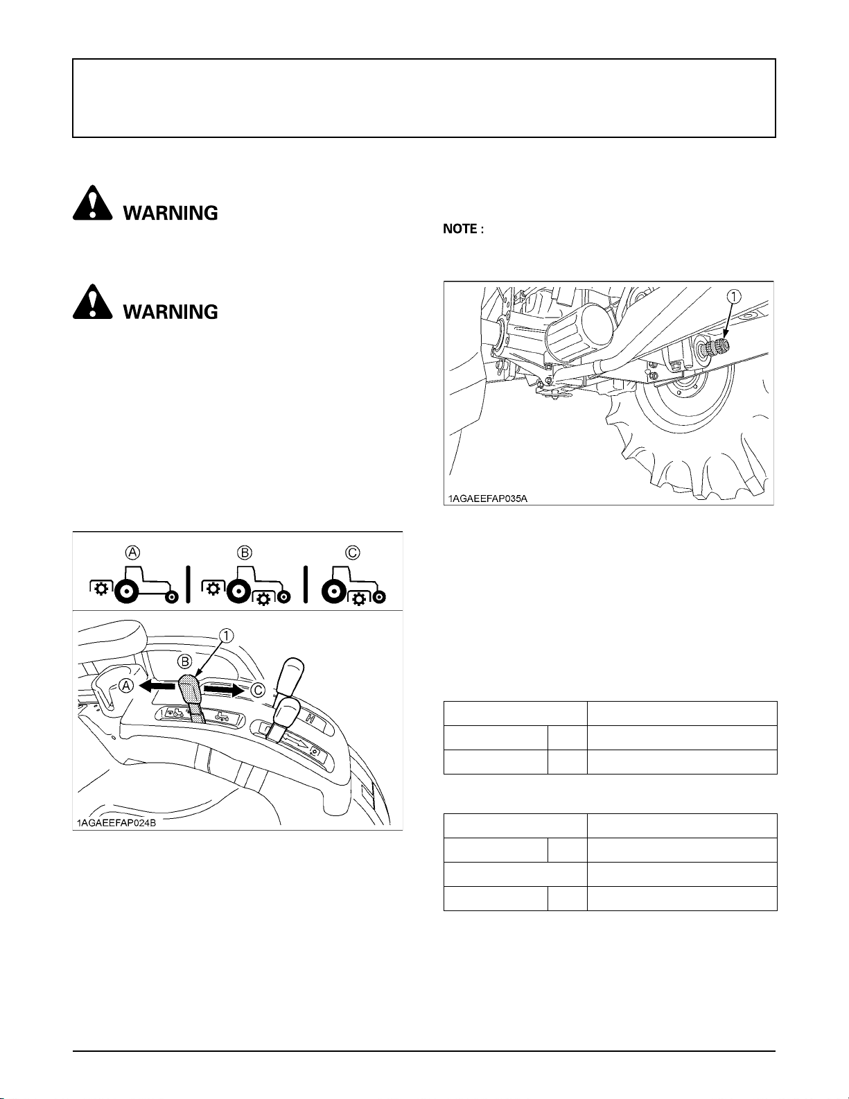
30 PTO
PTO
PTO OPERATION
To avoid personal injury or death:
A Before operation, be sure to select the correct
PTO lever (mid, mid/rear, rear).
To avoid personal injury or death:
A Disengage PTO, stop engine, set the parking
brake, lower appropriate implements, and allow
all rotating components to come to a complete
stop before connecting, disconnecting,
adjusting, or cleaning any PTO driven
equipment.
BPTO Select Lever
The tractor has a 540 rpm rear PTO speed and a 2 500
rpm mid-PTO speed.
C Mid-PTO
To use Mid-PTO, shift the PTO select lever to Mid-PTO
position and the PTO clutch lever to the "ON" position.
A The Mid-PTO is available for KUBOTA approved
implements.
(1) Mid-PTO
C Mid-Rear PTO
To use mid and rear PTO at the same time, shift the PTO
select lever to mid-rear PTO position and the PTO clutch
lever to the "ON" position.
(1) PTO select lever (A) Rear-PTO position
(B) Mid-Rear-PTO position
(C) Mid-PTO position
C Rear PTO
To use rear PTO, shift the PTO select lever to rear PTO
position and the PTO clutch lever to the "ON" position.
C Mid-PTO speed
B2301/B2601
Engine speed rpm 2753
PTO speed rpm 2500
C Rear PTO speed
B2301/B2601
Engine speed rpm 2768
Shaft 6-spline
PTO speed rpm 540
Page 49
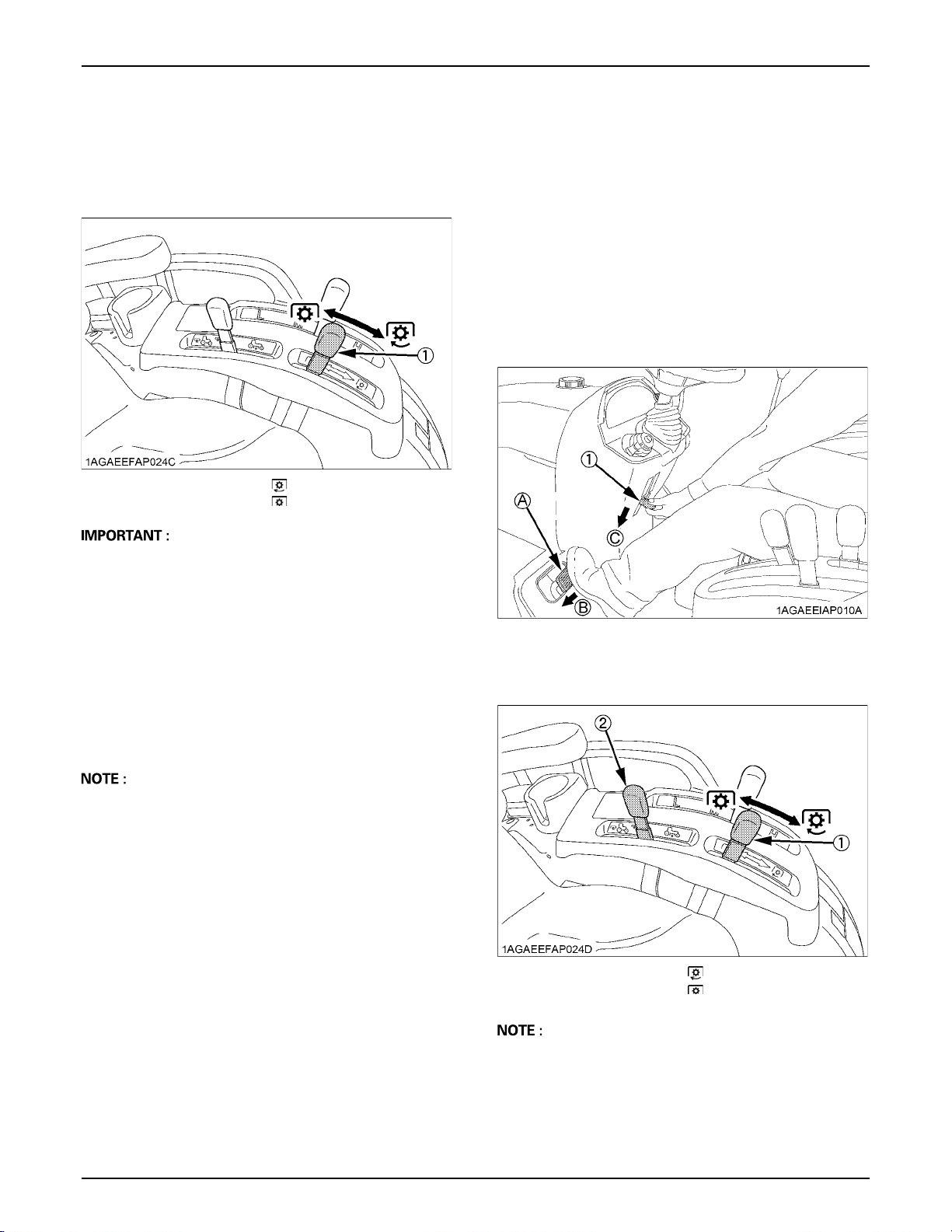
31PTO
BPTO Clutch Lever
1. The PTO clutch lever engages or disengages the PTO
clutch which gives the PTO independent control.
2. Shift the lever to "ON" to engage the PTO clutch. Shift
the lever to "OFF" to disengage the PTO clutch.
(1) PTO clutch lever "ON" "ENGAGE"
"OFF" "DISENGAGE"
A To avoid shock loads to the PTO, reduce engine
throttle from high idle to low idle by pushing up on
engine throttle when engaging the PTO, then open the
throttle to the recommended engine rpm.
A To avoid damage to PTO clutch and implement, shift
the PTO clutch lever slowly, when engaging the PTO
clutch. Do not keep the PTO clutch lever half way.
A To avoid damage of transmission, when PTO select
lever is not smoothly shifted, slightly shift PTO clutch
lever.
A To avoid damage of transmission, do not shift PTO
select lever until the PTO has stopped completely.
BStationary PTO
To park the tractor and use the PTO system (for chipper
or pump, for example), start the PTO system in the
following steps.
1. Apply the parking brake.
2. Make sure the shift levers are at NEUTRAL, and start
the engine.
3. Set the PTO select lever to rear only position.
4. Set the PTO clutch lever to engage "ON".
5. Set the engine speed to provide recommended rear
PTO speed.
6. Get off the tractor and place blocks at the tires.
(1) Parking brake lever (A) Interlock the brake pedals
(B) "DEPRESS"
(C) "PULL DOWN"
A Tractor engine will not start if the PTO clutch lever is in
the engaged "ON" position.
A When you stand up from the seat with the PTO clutch
lever in the "ON" position, the engine will stop
regardless of the position of the PTO select lever.
This is because the tractor is equipped with Operator
Presence Control system (OPC).
(1) PTO clutch lever
(2) PTO select lever
"ON"
"OFF"
A If the PTO system is engaged and you stand up from
the seat and release the parking brake, the engine
stops automatically after standing up.
Page 50
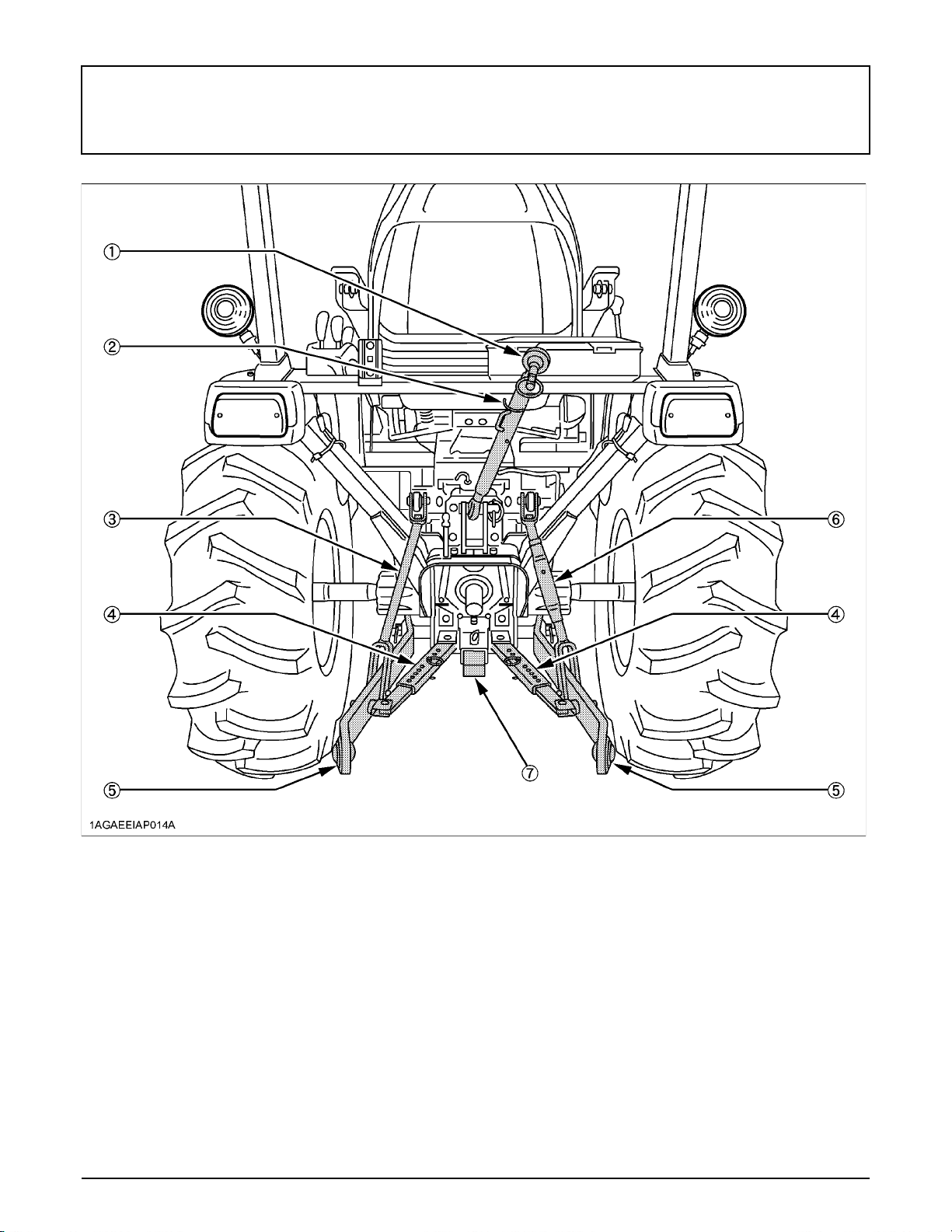
32 3-POINT HITCH & DRAWBAR
3-POINT HITCH & DRAWBAR
(1) Top link
(2) Top link holder
(3) Lifting rod (Left)
(4) Telescopic stabilizers
(5) Lower link
(6) Lifting rod (Right)
(7) Drawbar
Page 51
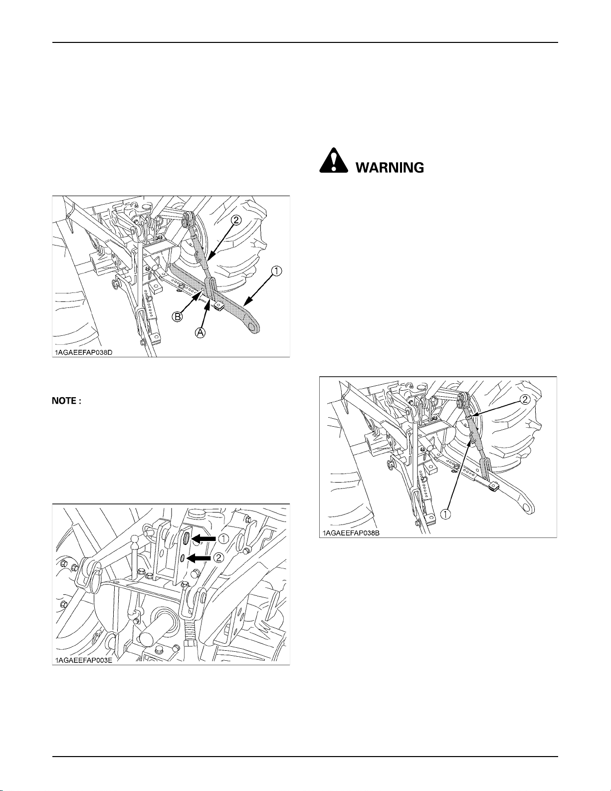
333-POINT HITCH & DRAWBAR
3-POINT HITCH
1. Make preparations for attaching
implement.
BSelecting the holes of lifting rods and
lower links
There are 2 holes in the lower links. For most operations
the lifting rods should be attached to the (A) holes.
(1) Lower links
(2) Lifting rods
Holes: (A), (B)
BDrawbar
Remove the drawbar if a close mounted implement is
being attached.
2. Attaching and detaching implements.
To avoid personal injury or death:
A Be sure to stop the engine and remove the key.
A Do not stand between tractor and implement
unless parking brake is applied.
A Before attaching or detaching implement,
locate the tractor and implement on a firm, flat
and level surface.
A Whenever an implement or other attachment is
connected to the tractor 3-point hitch, check
full range of operation for interference, binding
or PTO driveline separation.
BLifting Rod (Right)
Level a 3-point mounted implement from side to side by
turning the adjusting handle to shorten or lengthen the
adjustable lifting rod with the implement on the ground.
After adjustment, tighten the lock nut securely.
A The lifting rods may be attached to (B) hole for higher
lifting height (with reduced lifting force).
BSelecting the Top Link Mounting Holes
Select the proper set of holes by referring to the
"Hydraulic Control Unit Use Reference Chart" in
"HYDRAULIC UNIT" section.
(1) Mounting hole 1
(2) Mounting hole 2
(1) Adjusting handle
(2) Lock nut
BTop Link
1. Adjust the angle of the implement to the desired
position by shortening or lengthening the top link.
2. The proper length of the top link varies according to
the type of implement being used.
Page 52
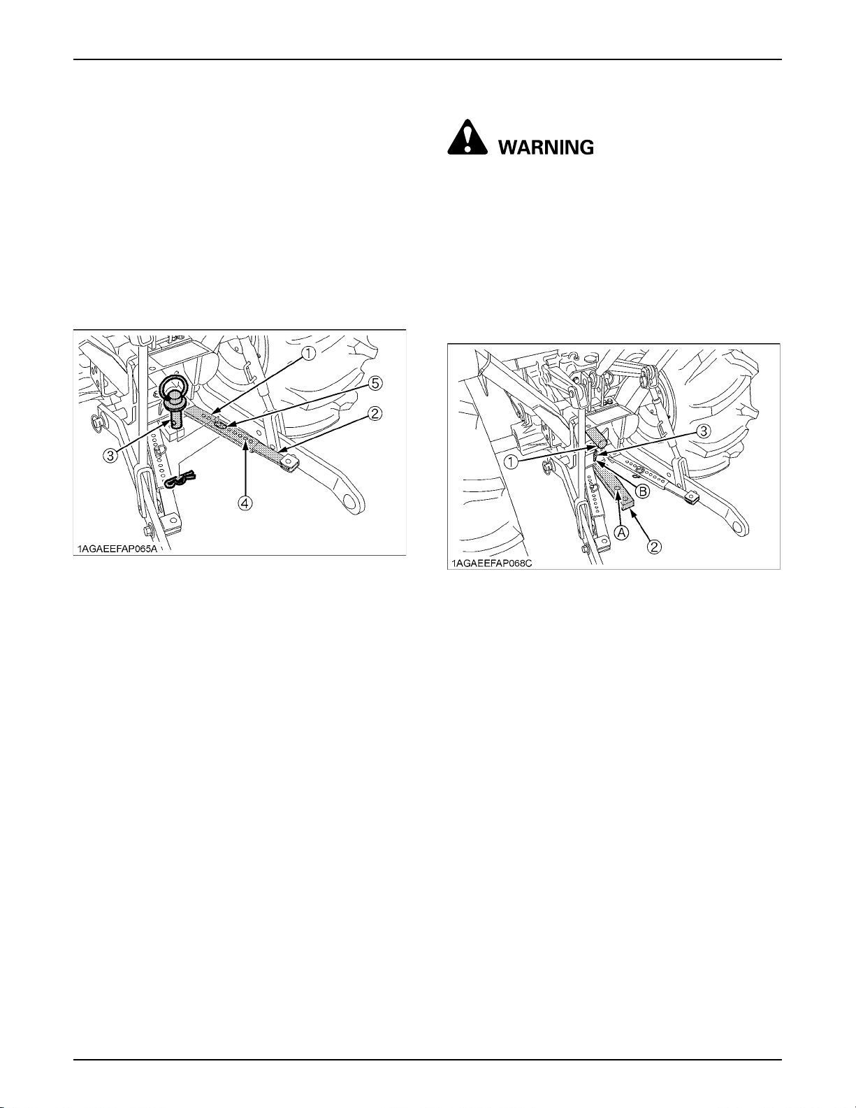
3-POINT HITCH & DRAWBAR34
BTelescopic Stabilizers
Adjust the telescopic stabilizers to control horizontal sway
of the implement. Select the proper set of holes by
referring to the "Hydraulic Control Unit Use Reference
Chart" in "AUXILIARY HYDRAULICS" in "HYDRAULIC
UNIT" section.
After aligning satisfactorily, insert the set-pin through any
one of the 8 holes on the outer tube that align with one of
the holes on the inner bar, both stabilizers will be locked.
If the set-pin is inserted through the slot to engage one of
the holes on the inner bar, a limited degree of sway will be
permitted.
DRAWBAR
To avoid personal injury or death:
A Never pull from the top link, the rear axle or any
point above the drawbar. Doing so could cause
the tractor to tip over rearward causing
personal injury or death.
BAdjusting Drawbar Length
When towing an implement, use of (B) hole in drawbar is
recommended.
The acceptable drawbar load is provided in the
"IMPLEMENT LIMITATIONS" section.
(1) Outer tube
(2) Inner bar
(3) Set-pin
(4) Hole
(5) Slot
(1) PTO Shaft cap
(2) Drawbar
(3) Drawbar pin
Hole: (A), (B)
Page 53
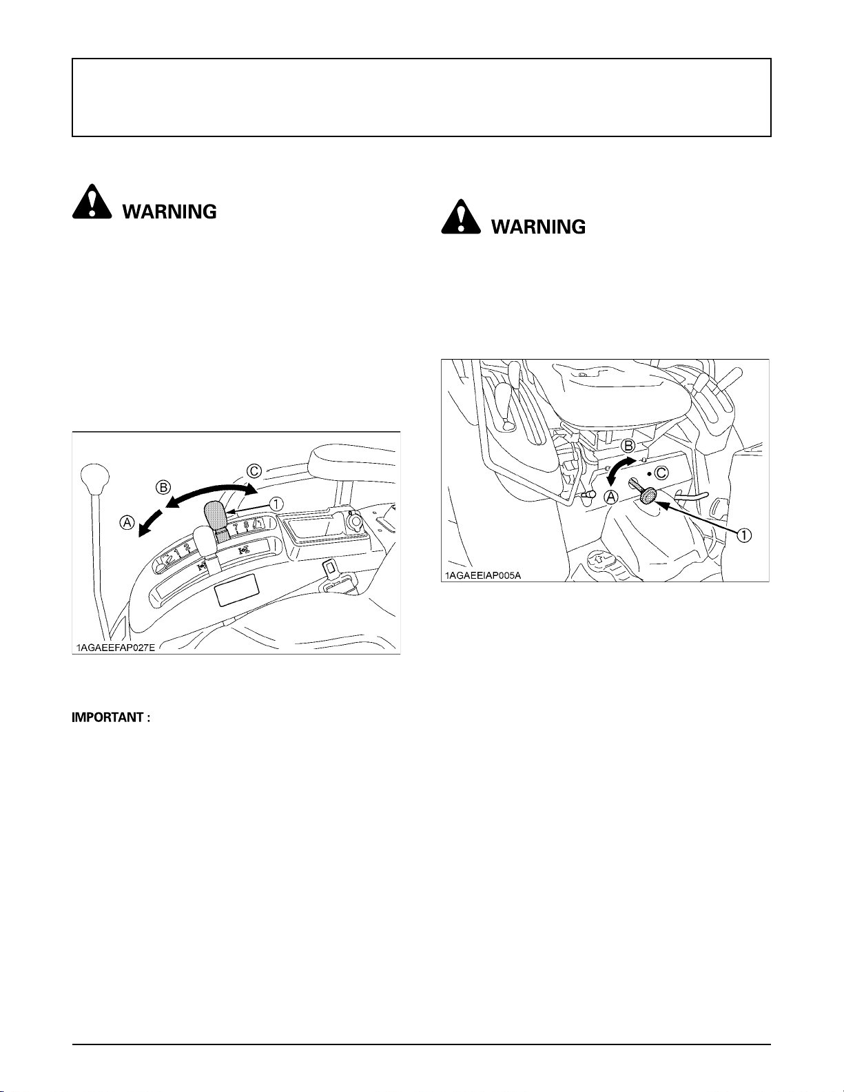
HYDRAULIC UNIT
35HYDRAULIC UNIT
3-POINT HITCH CONTROL SYSTEM
To avoid personal injury or death:
A Before using the 3-point hitch controls, ensure
that no person or object is in the area of the
implement or 3-point hitch. Do not stand on or
near the implement or between the implement
and tractor when operating the 3-point hitch
controls.
BPosition Control
This will control the working depth of 3-point hitch
mounted implement regardless of the amount of pull
required.
B3-point Hitch Lowering Speed
To avoid personal injury or death:
A Fast lowering speed may cause damage or
injury. Lowering speed of implement should be
adjusted to 2 or more seconds.
The lowering speed of the 3-point hitch can be controlled
by adjusting the 3-point hitch lowering speed knob.
(1) Position control lever (A) "FLOAT"
(B) "DOWN"
(C) "UP"
A If the 3-point hitch can not be raised by setting the
hydraulic control lever to the UP position after long
term storage or when changing the transmission oil,
turn steering wheel to the right and left several times
to bleed air from the system.
A Do not operate until the engine is warmed up. If
operation is attempted when the engine is still cold, the
hydraulic system may be damaged.
A If noises are heard when implement is lifting after the
hydraulic control lever has been activated, the
hydraulic mechanism is not adjusted properly. Unless
corrected, the unit will be damaged. Contact your
KUBOTA Dealer for adjustment.
(1) 3-Point hitch lowering speed knob (A) "FAST"
(B) "SLOW"
(C) "LOCK"
Page 54
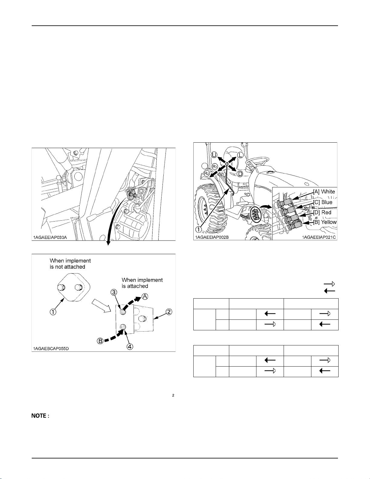
HYDRAULIC UNIT36
AUXILIARY HYDRAULICS
Hydraulic outlet (rear) is provided on the tractor.
BHydraulic Block Type Outlet
Hydraulic block type outlet is useful when adding
hydraulically operated equipment such as front end
loader, front blade, etc.
When an implement is attached
1. Remove the block cover.
2. Attach the block outlet cover. (option)
[Rear outlet]
Hydraulic outlets are provided on the tractor.
DUAL REMOTE HYDRAULIC CONTROL SYSTEM
The tractor is equipped with the double-acting 2-segment
hydraulic control valve for the front loader.
To apply the hydraulic power take-off for general
attachments, keep the following point in mind.
BControl Lever and Hydraulic Hose
Connections
Connect the control lever in its specified direction and the
hydraulic hoses to their specified ports.
(1) Block cover
(2) Block outlet cover (option)
(3) Outlet
(4) Inlet
A If the implement control valve has a relief valve, the
tank port flow from implement should be connected to
the port located on the right hand side of transmission
case.
(A) To implement inlet
Max. flow
17.9 L/min
(4.7 U.S.gals./min)
Max. pressure
13.0 to 13.8 MPa
(133 to 141 kgf/cm )
(1891 to 2005 psi)
(B) from implement outlet
(1) Loader / Remote control valve lever (R) "RIGHT"
(L) "LEFT"
(U) "UP"
(D) "DOWN"
Pressure
Hydraulic outlet ports of first segment
Lever UP DOWN
[A] In Out
Port
[B] Out In
Hydraulic outlet ports of second segment
Lever RIGHT LEFT
[C] In Out
Port
[D] Out In
Returning
Page 55
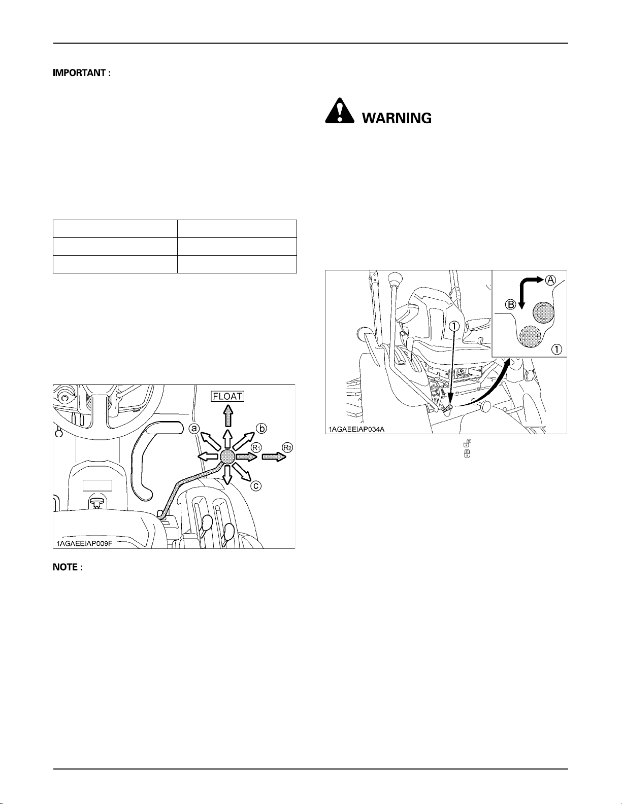
37HYDRAULIC UNIT
To avoid damage of the attachments:
A Do not connect attachments through the hydraulic
motor to the [C] and [D] ports. If the control lever is
moved to the Regeneration position (R1), the seals on
the hydraulic motor will be damaged.
A This control valve is provided with the Regeneration
position. When the [C] and [D] ports are used to take
off hydraulic power for the hydraulic cylinder, be sure
to connect the [C] port to the "Head-End" side port of
the hydraulic cylinder.
A Make the following connections when using this valve
to take off hydraulic power for the hydraulic cylinder.
Colored Coupler Hydraulic Cylinder port
[B: Yellow], [C: Blue] Head-End side
[A: White], [D: Red] Rod-End side
BLoader / Remote Control Valve Lever
1. Before moving the lever, make sure that the hydraulic
hoses for attachments are connected.
2. Move the lever diagonally (a, b, c shown in the figure),
and the first and second segments can be controlled
simultaneously.
BValve Lock
To avoid injury or death from crushing:
A Do not utilize the valve lock for machine
maintenance or repair.
A The valve lock is to prevent accidental
actuation when implement is not in use or
during transport.
The control valve is equipped with a valve lock feature.
The control valve is locked in the "LOCK" position.
The lock is not intended and will not prevent a leak down
of the implement during the period of storage.
A Move the lever to the "FLOAT" position, and it will be
held there by the detent mechanism. To use the valve
as a floating valve with detents, connect the hydraulic
hoses to ports [A] and [B].
A When taking off hydraulic power from port [D], the flow
rate can be adjusted in 2 stages with the lever.
The flow rate is high at position (R1) and low at
position (R2). Move the lever to position (R1) or (R2)
depending on the attachment in use.
(1) Lock lever (A) "UNLOCK"
(B) "LOCK"
Page 56
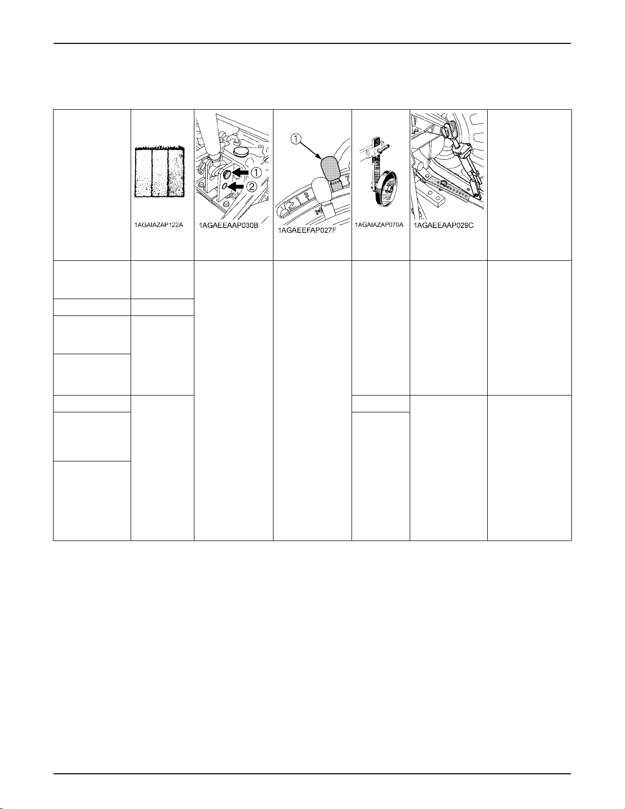
38 HYDRAULIC UNIT
BHydraulic Control Unit Use Reference Chart
In order to handle the hydraulics properly, the operator must be familiar with the following. Though this information may not
be applicable to all types of implements and soil conditions, it is useful for general conditions.
Implement
Soil condition
Light soil
Moldboard plow
Disc plow ---
Harrower (spike,
springtooth, disc
type)
Sub-soiler .........
Weeder, ridger
Earthmover,
digger, scraper,
manure fork, rear
carrier ......
Mower (mid-and
rear-mount type),
hayrake, tedder...
Medium soil
Heavy soil
---
---
Top link mounting
holes
(1) is standard.
(2) is used only
when there is
some obstacle
that prevents you
from using the
standard.
(1) Position
control lever
Position control
Gauge
wheel
YES/NO Loose
YES
YES/NO
Telescopic
stabilizers
Tighten
Remarks
Insert the set-pin
through the slot on
the outer tube that
align with one of the
holes on the inner
bar.
For implements
with gauge wheels,
lower the
implements to the
ground.
Telescopic
stabilizer should be
tight enough to
prevent excessive
implement
movement when
implement is in
raised position.
For implements
with gauge wheels,
lower the
implements to the
ground.
Page 57
39TIRES, WHEELS AND BALLAST
TIRES, WHEELS AND BALLAST
TIRES
To avoid personal injury or death:
A Do not attempt to mount a tire on a rim. This
should be done by a qualified person with the
proper equipment.
A Always maintain the correct tire pressure.
Do not inflate tires above the recommended
pressure shown in the operator's manual.
A Do not use tires other than those approved by
KUBOTA.
BInflation Pressure
Though the tire pressure is factory-set to the prescribed
level, it naturally drops slowly over the course of time.
Thus, check it regularly and inflate as necessary.
Tire sizes Inflation Pressure
140kPa(1.4kgf/cm , 20psi)
160kPa(1.6kgf/cm , 23psi)
100kPa(1.0kgf/cm , 14psi)
130kPa(1.3kgf/cm , 18psi)
270kPa(2.7kgf/cm , 40psi)
140kPa(1.4kgf/cm , 20psi)
140kPa(1.4kgf/cm , 20psi)
200kPa(2.0kgf/cm , 28psi)
170kPa(1.7kgf/cm , 24psi)
160kPa(1.6kgf/cm , 23psi)
150kPa(1.5kgf/cm , 22psi)
250kPa(2.5kgf/cm , 35psi)
160kPa(1.6kgf/cm , 23psi)
Rear
Front
9.5 - 16, 4PR
9.5 - 18, 4PR
315/75D - 15, 4PR
11.2 - 16, 4PR
12 - 16.5, 4PR
31x15.5 - 15, 4PR
33x12.5 - 15, 4PR
6 - 12, 4PR
7 - 12, 4PR
21x8.00 - 10, 4PR
23x8.50 - 12Turf, 4PR
23x8.50 - 12Ind., 4PR
24x8.50 - 12, 4PR
WHEEL ADJUSTMENT
To avoid personal injury or death:
A When working on slopes or when working with
trailer, set the wheel tread as wide as practical
for maximum stability.
A Support tractor securely on stands before
removing a wheel.
A Do not work under any hydraulically supported
devices. They can settle, suddenly leak down,
or be accidentally lowered. If necessary to work
under tractor or any machine elements for
servicing or adjustment, securely support them
with stands or suitable blocking beforehand.
A Never operate tractor with a loose rim, wheel,
or axle.
BDual Tires
Dual tires are not approved.
Page 58
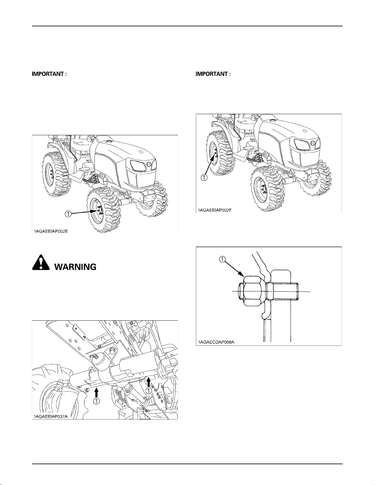
TIRES, WHEELS AND BALLAST40
BFront Wheels
Front tread width can not be adjusted.
A Do not turn front discs to obtain wider tread.
In setting up the front wheels, make sure that the
inflation valve stem of the tires face outward.
A When re-fitting or adjusting a wheel, tighten the bolts
to the following torques then recheck after driving the
tractor 200 m (200 yards) and 10 times of shuttle
movement by 5 m (5 yards), and thereafter according
to service interval. (See "MAINTENANCE" section.)
BRear Wheels
Rear tread width can not be adjusted.
A When re-fitting or adjusting a wheel, tighten the bolts
to the following torques then recheck after driving the
tractor 200 m (200 yards) and 10 times of shuttle
movement by 5 m (5 yards), and thereafter according
to service interval. (See "MAINTENANCE" section.)
(1) 145 to 150 N-m (14.8 to 15.3 kgf-m, 107.0 to 110.6 ft-lbs)
(1) 79 to 92 N-m (8.1 to 9.4 kgf-m, 58.3 to 67.9 ft-lbs)
To avoid personal injury or death:
A Before jacking up the tractor, park it on a firm
and level ground and chock the rear wheels.
A Fix the front axle to keep it from pivoting.
A Select jacks that withstand the machine weight
and set them up as shown below.
[Wheels with beveled or tapered holes]
A Use the tapered side of lug nut.
(1) Lug nut
(1) Jack point
Page 59
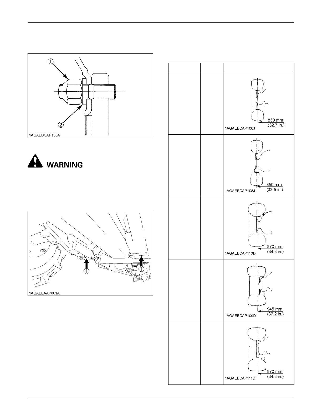
[Wheels without beveled or tapered holes]
A Use the flat side of the lug nut. Make sure to apply the
spring washer.
41TIRES, WHEELS AND BALLAST
BTreads
C Front
[USA models]
Tire Models Tread
(1) Lug nut
(2) Spring washer
To avoid personal injury or death:
A Before jacking up the tractor, park it on a firm
and level ground and chock the front wheels.
A Fix the front axle to keep it from swinging.
A Select jacks that withstand the machine weight
and set them up as shown below.
6 - 12
Farm
7 - 12
Farm
23x8.50 - 12
Turf
B2301
B2601
B2301
B2601
(1) Jack point
21x8.00 - 10
Bar
23x8.50 - 12
Ind.
B2301
B2601
B2301
B2601
Page 60
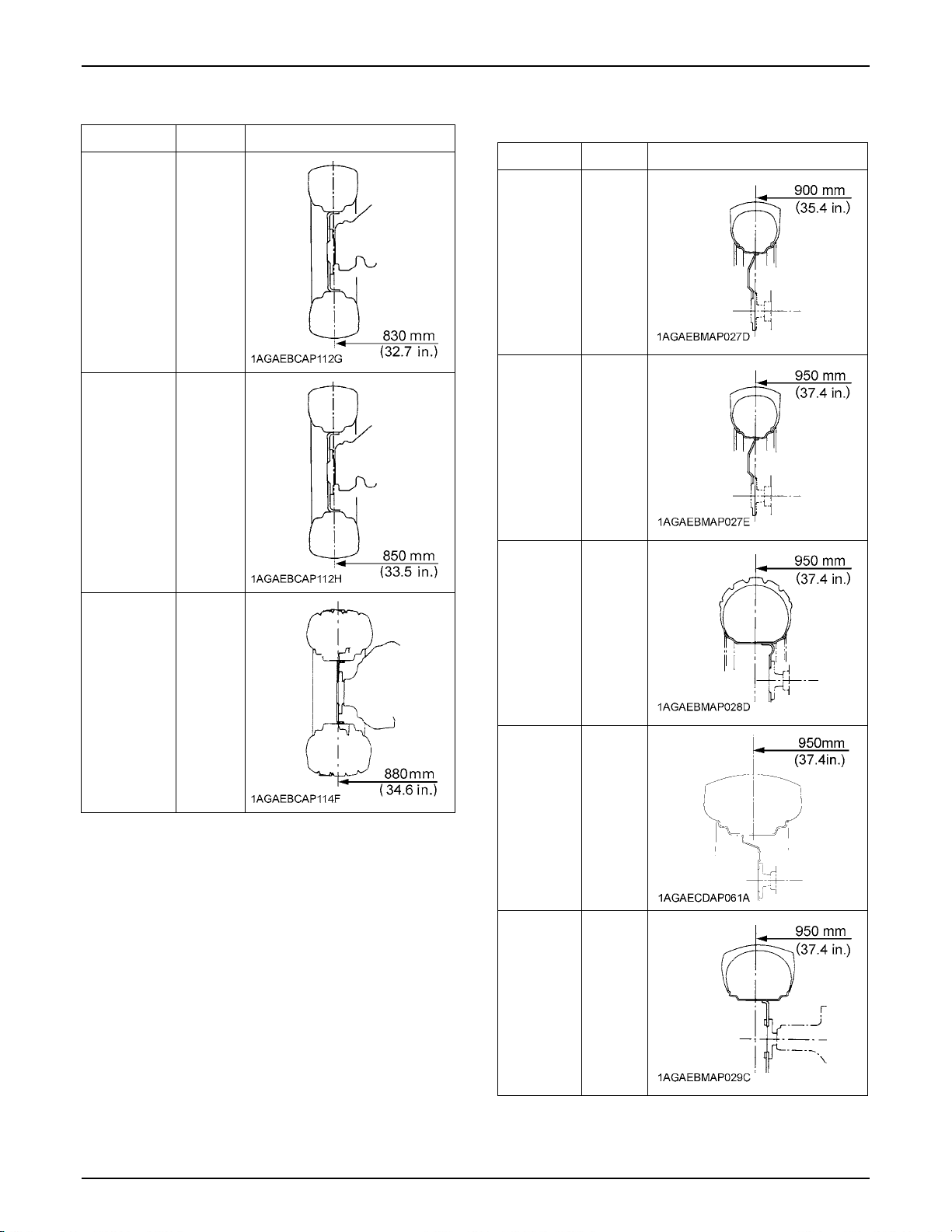
TIRES, WHEELS AND BALLAST42
[Except USA models] C Rear
Tire Models Tread
[USA models]
Tire Models Tread
6 - 12
Farm
7 - 12
Farm
24x8.50 - 12
Turf
B2301
B2601
B2301
B2601
9.5 - 16
Farm
11.2 - 16
Farm
33x
12.5 - 15
Turf
B2301
B2601
B2301
B2601
31x
15.5 - 15
Bar
12 - 16.5
Ind.
B2301
B2601
B2301
B2601
Page 61
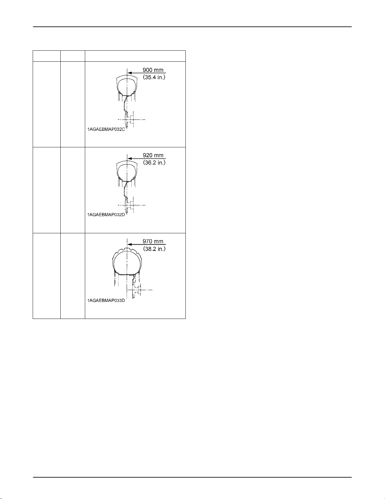
[Except USA models]
Tire Models Tread
43TIRES, WHEELS AND BALLAST
9.5 - 16
Farm
9.5 - 18
Farm
315/75D
- 15
Turf
B2301
B2601
B2301
B2601
Page 62
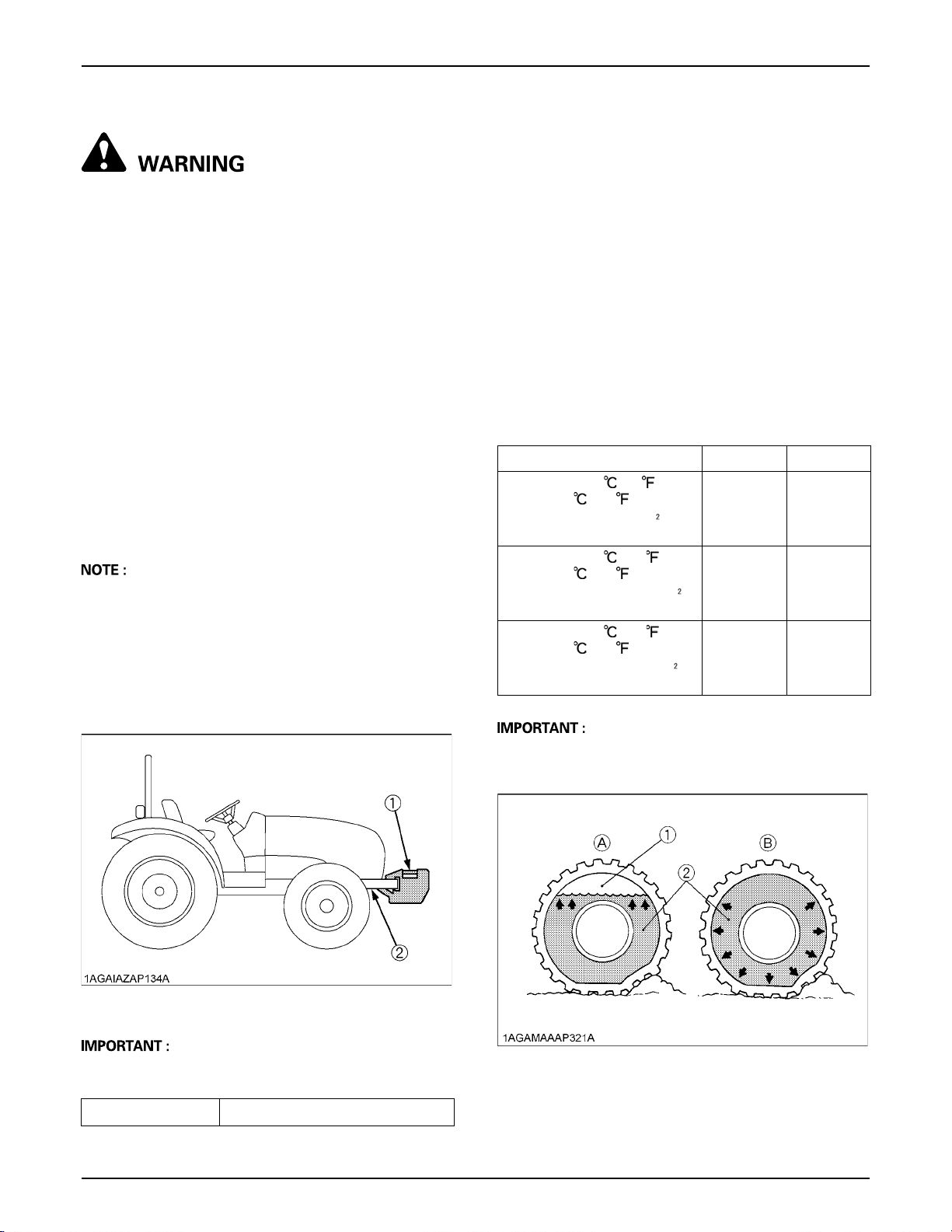
TIRES, WHEELS AND BALLAST44
BALLAST
To avoid personal injury or death:
A Additional ballast will be needed for
transporting heavy implements. When the
implement is raised, drive slowly over rough
ground, regardless of how much ballast is
used.
A Do not fill the front wheels with liquid.
BFront Ballast
Add weights if needed for stability and improving traction.
Heavy pulling and heavy rear mounted implements tend
to lift front wheels. Add enough ballast to maintain
steering control and prevent tip over.
Remove weight when no longer needed.
C Front End Weights (option)
The front end weights can be attached to the bumper.
See your implement operator's manual for required
number of weights or consult your local KUBOTA Dealer
to use.
[For installation of up to 3 weights]
A Besides the weight, mounting bolt kit(s) are required
for mounting the weight.
[For installation of up to 5 weights]
A Besides the weight, a front weight bracket and
mounting bolt kit(s) are required for mounting the
weight.
BRear Ballast
Add weight to rear wheels if needed to improve traction or
for stability. The amount of rear ballast should be matched
to job and the ballast should be removed when it is not
needed.
The weight should be added to the tractor in the form of
liquid ballast.
C Liquid Ballast in Rear Tires
Water and calcium chloride solution provides safe
economical ballast. Used properly, it will not damage tires,
tubes or rims. The addition of calcium chloride is
recommended to prevent the water from freezing. Use of
this method of weighting the wheels has the full approval
of the tire companies. See your tire dealer for this service.
Liquid weight per tire (75 Percent filled)
Tire sizes 9.5 - 16 11.2-16
Slush free at -10 (14 )
Solid at -30 (-22 )
[Approx. 1 kg(2 lbs.) CaCl per
4L (1 gal.) of water]
Slush free at -24 (-11 )
Solid at -47 (-52 )
[Approx. 1.5 kg(3.5 lbs.) CaCl
per 4L (1 gal.) of water]
Slush free at -47 (-52 )
Solid at -52 (-62 )
[Approx. 2.25 kg(5 lbs.) CaCl
per 4L (1 gal.) of water]
54 kg
(119 lbs.)
57 kg
(126 lbs.)
60 kg
(132 lbs.)
70 kg
(155 lbs.)
74 kg
(163 lbs.)
78 kg
(172 lbs.)
(1) Front end weights (option)
(2) Front weight bracket (option)
A Do not overload tires.
A Add no more weight than indicated in chart.
Maximum weight 25 kg x 5 pieces (125 kg (275lbs.))
A Do not fill tires with water or solution more than 75% of
full capacity (to the level of valve stem at 12 o'clock
position).
(1) Air
(2) Water
(A) Correct: 75% Full
Air compresses like a cushion
(B) Incorrect: 100% Full
Water can not be compressed
Page 63
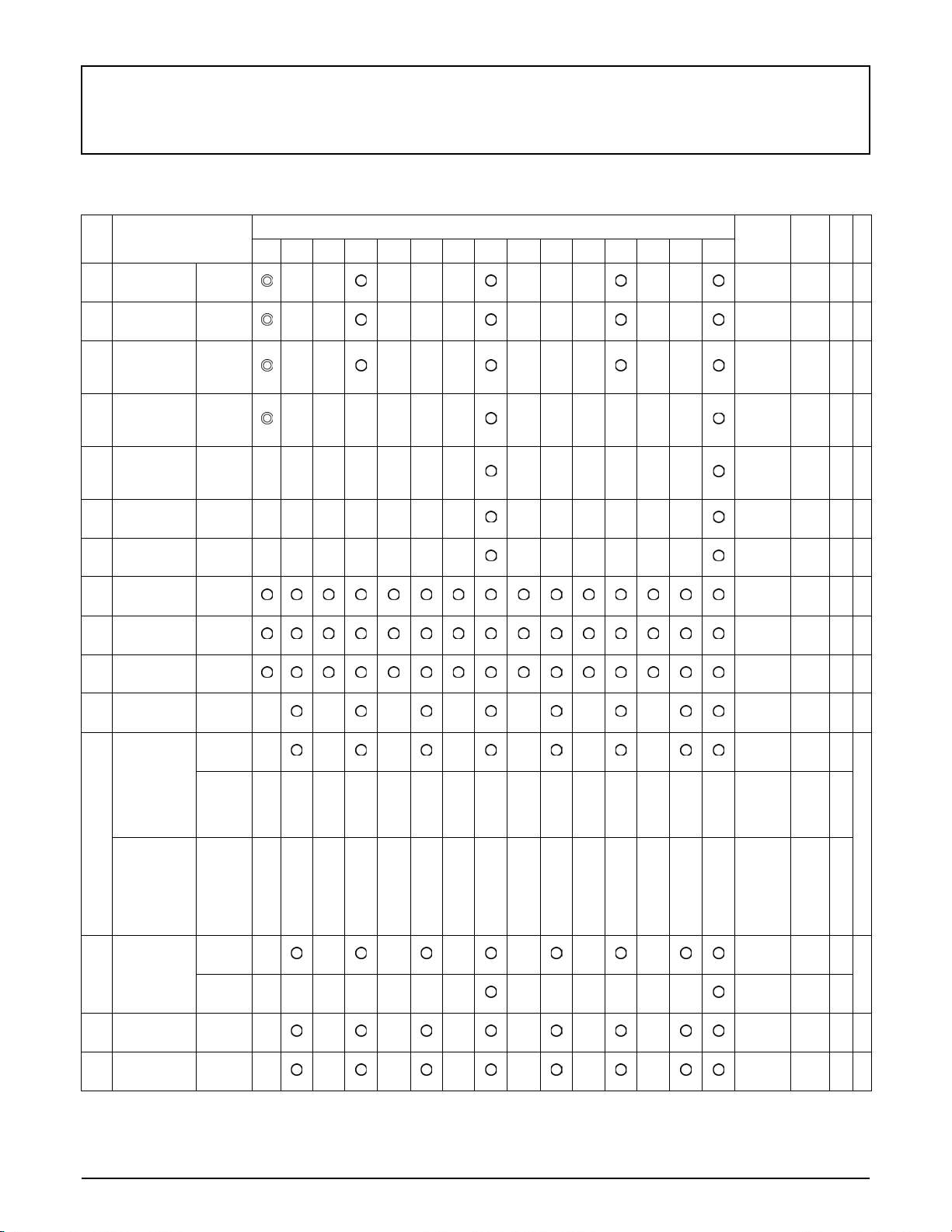
MAINTENANCE
SERVICE INTERVALS
45MAINTENANCE
No. Items
1 Engine oil Change
Engine oil
2
filter
Transmission
3
oil filters
[HST]
Hydraulic oil
4
filter
Transmission
5
fluid
Front axle
6
case oil
Front axle
7
pivot
Engine start
8
system
9Greasing -
Wheel bolt
10
torque
Battery
11
condition
Air cleaner
element
[Double
element type]
Primary
element
12
Air cleaner
element
[Double
element type]
Secondary
element
Fuel filter
13
element
14 Fan belt Adjust
15 Brake Adjust
Replace
Replace
Replace
Change
Change
Adjust
Check
Check
Check
Clean
Replace
Replace
Clean
Replace
Indication on hour meter
50 100 150 200 250 300 350 400 450 500 550 600 650 700 800
Interval
every
200 Hr
every
200 Hr
every
200 Hr
every
400 Hr
every
400 Hr
every
400 Hr
every
400 Hr
every
50 Hr
every
50 Hr
every
50 Hr
every
100 Hr
every
100 Hr
every
1000 Hr
or
1 year
every
1000 Hr
or
ear
1 y
every
100 Hr
every
400 Hr
every
100 Hr
every
100 Hr
Ref.
page
61
60
61
63
62
65
64
55
55
56
56 *4
58 *1
65 *5
@
65 *5
58
@
64
59
60
Page 64
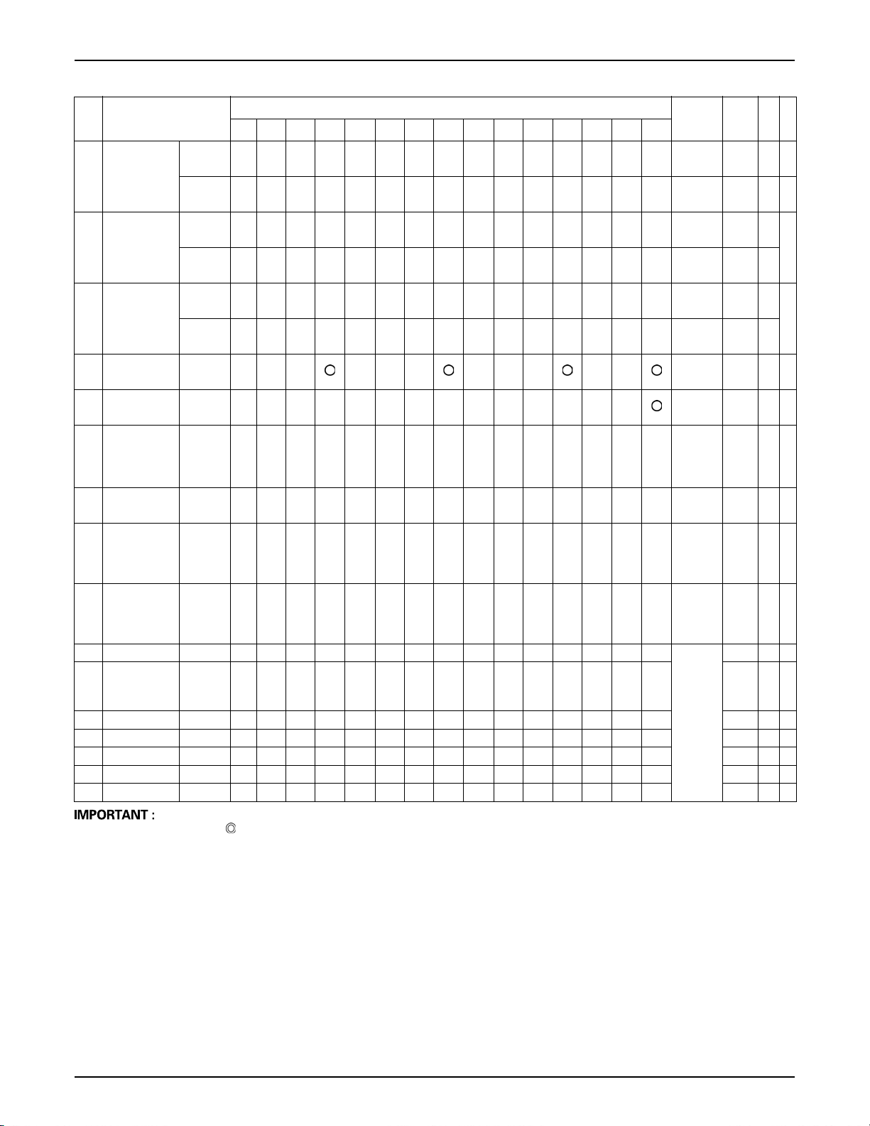
46 MAINTENANCE
No. Items
Radiator
16
hose and
clamp
17 Fuel line
18 Intake air line
19 Toe-in Adjust
Engine valve
20
clearance
Fuel injection
nozzle
21
Injection
pressure
Injection
22
pump
Cooling
23
system
24 Coolant Change
25 Fuel system Bleed
Clutch
26
housing
water
27 Fuse Replace 71
28 Light bulb Replace 71
29 Fuel line Replace 71 *8
30 Radiator Replace 71 *8
31 Intake air line Replace 71 *8
Check
Replace
Check
Replace
Check
Replace
Adjust
Check
Check
Flush
Drain 70
50 100 150 200 250 300 350 400 450 500 550 600 650 700 800
Indication on hour meter
Interval
every
1 year
every
4 year
every
1 year
every
4 year
every
1 year
every
4 year
every
200 Hr
every
800 Hr
every
1500 Hr
every
3000 Hr
every
2000 Hr
2 year
every
2000 Hr
2 year
service
required
or
or
as
Ref.
page
67 *8
70 *8
68 *8
70
67 *8
70
62
65 *3
65 *3 @
67 *3 @
65 *7
65 *7
70
@
*2
*8
@
*2
*8
A The jobs indicated by must be done after the first 50 hours of operation.
*1 Air cleaner should be cleaned more often in severe dusty conditions.
*2 Replace only if necessary.
*3 Consult your local KUBOTA Dealer for this service.
*4 When the battery is used for less than 100 hours per year, check the fluid level annually.
*5 Replace in 1,000 hours or 1 year, whichever comes faster.
*6 Check in 1,000 hours or 1 year, whichever comes faster.
*7 Replace in 2,000 hours or 2 years, whichever comes faster.
*8 Replace if any deterioration (crack, hardening, scar or deformation) or damage occurred.
However, must be replaced every 4 years regardless of the condition.
A The items listed above (@ marked) are registered as emission related critical parts by KUBOTA in the U.S.EPA nonroad
emission regulation. As the engine owner, you are responsible for the performance of the required maintenance on the
engine according to the above instruction.
Please see the Warranty Statement in detail.
Page 65
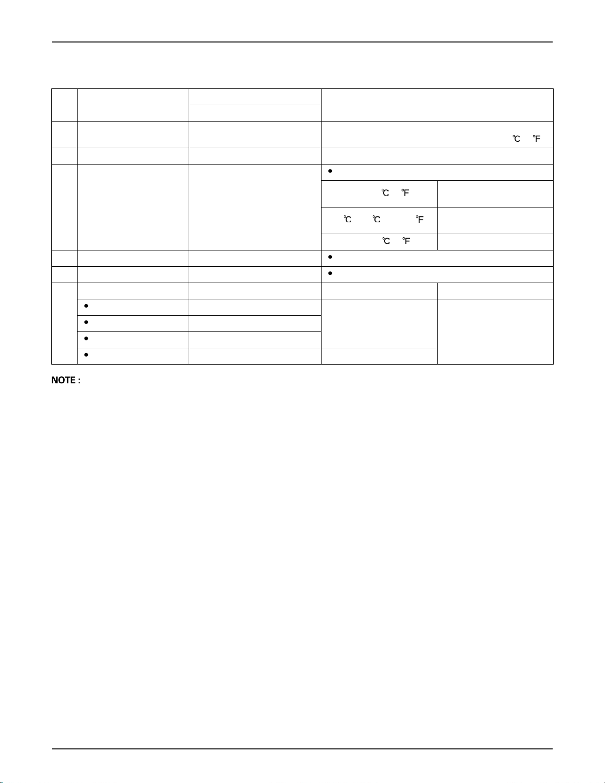
LUBRICANTS, FUEL AND COOLANT
47MAINTENANCE
No. Locations
1 Fuel 23 L (6.1 U.S.gals.)
2 Coolant (with recovery tank) 3.8 L (4.0 U.S.qts.) Fresh clean soft water with anti-freeze
Engine crankcase
3
(with filter)
4 Transmission case 15 L (4.0 U.S.gals.) KUBOTA SUPER UDT-2 fluid
5 Front axle case 3.5 L (3.7 U.S.qts.) KUBOTA SUPER UDT-2 fluid or SAE80 - SAE 90 gear oil
Greasing No. of greasing points Capacity Type of grease
Top link 1
Lift rod [RH] 1
6
Brake pedal 1
Battery terminals 2 moderate amount
Capacities
B2301/B2601
3.1 L (3.3 U.S.qts.)
Lubricants
No. 2-D S15 diesel fuel
No. 1-D S15 diesel fuel if temperature is below -10 (14 )
Engine oil : Refer to next page.
Above 25 (77 )
-10 to 25 (14 to 77 )
Below -10 (14 ) SAE10W-30
Until grease overflows
SAE30,
SAE10W-30 or 15W-40
SAE20,
SAE10W-30 or 15W-40
Multipurpose Grease
NLGI-2 OR NLGI-1
(GC-LB)
The product name of KUBOTA genuine UDT fluid may be different from that in the Operator’s Manual depending on
countries or territories. Consult your local KUBOTA Dealer for further details.
Page 66
48 MAINTENANCE
For North American market
C Engine Oil:
A Oil used in the engine should have an American Petroleum Institute (API) service classification and Proper SAE
Engine Oil according to the ambient temperatures as shown above:
A Refer to the following table for the suitable API classification engine oil according to the engine type (with internal
EGR, external EGR or non-EGR) and the fuel.
Fuel used
Ultra Low Sulfur Fuel
[<0.0015% (15 ppm)]
EGR: Exhaust Gas Re-circulation
A The CJ-4 engine oil is intended for DPF (Diesel Particulate Filter) type engines, and cannot be used on this tractor.
Models B2301 / B2601 ---
C Fuel:
A Cetane number of 45 is minimum. Cetane number greater than 50 is preferred, especially for temperatures below
-20 (-4 ) or elevations above 1500 m (5000 ft).
A Diesel fuels specified to EN 590 or ASTM D975 are recommended.
A No.2-D is a distillate fuel of lower volatility for engines in industrial and heavy mobile service. (SAE J313 JUN87)
C Transmission Oil:
*KUBOTA Super UDT-2: For an enhanced ownership experience, we highly recommend Super UDT-2 to be used
instead of standard hydraulic/transmission fluid.
Super UDT-2 is a proprietary KUBOTA formulation that delivers superior performance and protection in all operating
conditions.
Regular UDT is also permitted for use in this machine.
A Indicated capacities of water and oil are manufacturer's estimate.
Oil class of engines except external EGR Oil class of engines with external EGR
CF, CF-4, CG-4, CH-4 or CI-4
except external EGR with external EGR
Engine oil classification (API classification)
CF or CI-4
(Class CF-4, CG-4 and CH-4 engine oils
cannot be used on EGR type engines)
Page 67
For other than North American market
C Engine Oil:
A Oil used in the engine should have an American Petroleum Institute (API) service classification and Proper SAE
Engine Oil according to the ambient temperatures as shown above:
A With the emission control now in effect, the CF-4 and CG-4 lubricating oils have been developed for use of a low-
sulfur fuel on on-road vehicle engines. When an off-road vehicle engine runs on a high-sulfur fuel, it is advisable to
employ the "CF or better" lubricating oil with a high Total Base Number (TBN of 10 minimum).
A Refer to the following table for the suitable API classification engine oil according to the engine type (with internal
EGR, external EGR or non-EGR) and the fuel (low-sulfur or high-sulfur fuel).
49MAINTENANCE
Fuel used
High Sulfur Fuel
[ 0.05% (500 ppm)]
Low Sulfur Fuel
[<0.05% (500 ppm)] or
Ultra Low Sulfur Fuel
[<0.0015% (15 ppm)]
EGR: Exhaust Gas Re-circulation
A The CJ-4 engine oil is intended for DPF (Diesel Particulate Filter) type engines, and cannot be used on this tractor.
Models B2301 / B2601 ---
C Fuel:
A Cetane number of 45 minimum. Cetane number greater than 50 is preferred, especially for temperatures below
-20 or elevations above 1500 m.
A If diesel fuel with sulfur content greater than 0.5% (5000 ppm) sulfur content is used, reduce the service interval for
engine oil and filter by 50%.
A NEVER use diesel fuel with sulfur content greater than 0.05% (500 ppm) for EXTERNAL EGR type engine.
A DO NOT use diesel fuel with sulfur content greater than 1.0% (10000 ppm).
A Diesel fuels specified to EN 590 or ASTM D975 are recommended.
A No.2-D is a distillate fuel of lower volatility for engines in industrial and heavy mobile service. (SAE J313 JUN87)
C Transmission Oil:
The oil used to lubricate the transmission is also used as hydraulic fluid. To ensure proper operation of the hydraulic
system and to complete lubrication of the transmission, it is important that a multi-grade transmission fluid is used in
this system. We recommend the use of KUBOTA UDT or SUPER UDT fluid for optimum protection and performance.
(Consult your local KUBOTA Dealer for further detail.)
Do not mix different brands together.
A Indicated capacities of water and oil are manufacturer's estimate.
Oil class of engines except external EGR Oil class of engines with external EGR
CF
(If the "CF-4, CG-4, CH-4 or CI-4" lubricating oil is
used with a high-sulfur fuel, change the lubricating
oil at shorter intervals. (approximately half))
CF, CF-4, CG-4, CH-4 or CI-4
except external EGR with external EGR
Engine oil classification (API classification)
---
CF or CI-4
(Class CF-4, CG-4 and CH-4 engine oils
cannot be used on EGR type engines)
Page 68
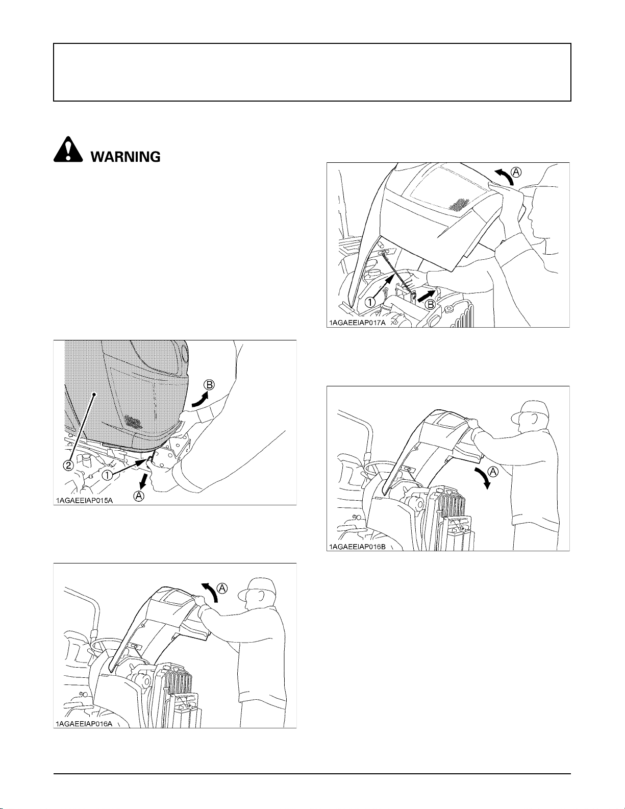
50 PERIODIC SERVICE
PERIODIC SERVICE
HOW TO OPEN THE HOOD
To avoid personal injury or death from contact
with moving parts;
A Never open the hood or engine side cover while
the engine is running.
A Do not touch muffler or exhaust pipes while
they are hot; Severe burns could result.
A Support hood with other hand while unlocking
support rod.
BHood
C Open the hood
1. Slightly pull up the hood to unlock it with pulling the
release lever.
C Close the hood
1. To close the hood, hold the hood and release the
support rod.
(1) Support rod (A) "HOLD"
(B) "PULL"
2. In closing the hood, use both hands again.
(1) Release lever
(2) Hood
2. Open the hood by holding its bottom with both hands.
(A) "PULL"
(B) "SLIGHTLY PULL UP"
(A) "OPEN"
(A) "CLOSE"
Page 69
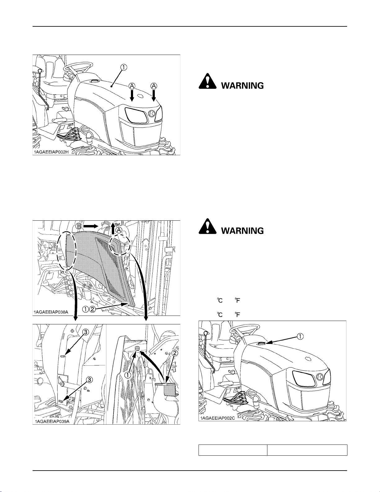
51PERIODIC SERVICE
3. Push the hood with both hands to lock it securely.
(1) Hood (A) "PUSH"
BEngine Side Cover
A Removing the side cover
1. Lift up the engine side cover and free the upper and
lower projections.
2. Pull the cover toward "B" and detach the notch.
A Attaching the side cover
To attach the cover, take the reverse order.
DAILY CHECK
To avoid personal injury or death:
Take the following precautions when checking the
tractor.
A Park the machine on firm and level ground.
A Set the parking brake.
A Lower the implement to the ground.
A All residual pressure of the hydraulic system
released.
A Stop the engine and remove the key.
BWalk Around Inspection
Look around and under the tractor for such items as loose
bolts, trash build-up, oil or coolant leaks, broken or worn
parts.
BChecking and Refueling
To avoid personal injury or death:
A Do not smoke while refueling.
A Be sure to stop the engine before refueling.
1. Turn the key switch to "ON", check the amount of fuel
by fuel gauge.
2. Fill fuel tank when fuel gauge shows 1/4 or less fuel in
tank.
3. Use grade No.2-Diesel fuel at temperatures above
-10 (14 ).
Use grade No.1-Diesel fuel at temperatures below
-10 (14 ).
(1) Projection
(2) Hole
(3) Notch
(A) "LIFT UP"
(B) "PULL"
(1) Fuel tank cap
Fuel tank capacity 23 L (6.1 U.S.gals.)
Page 70
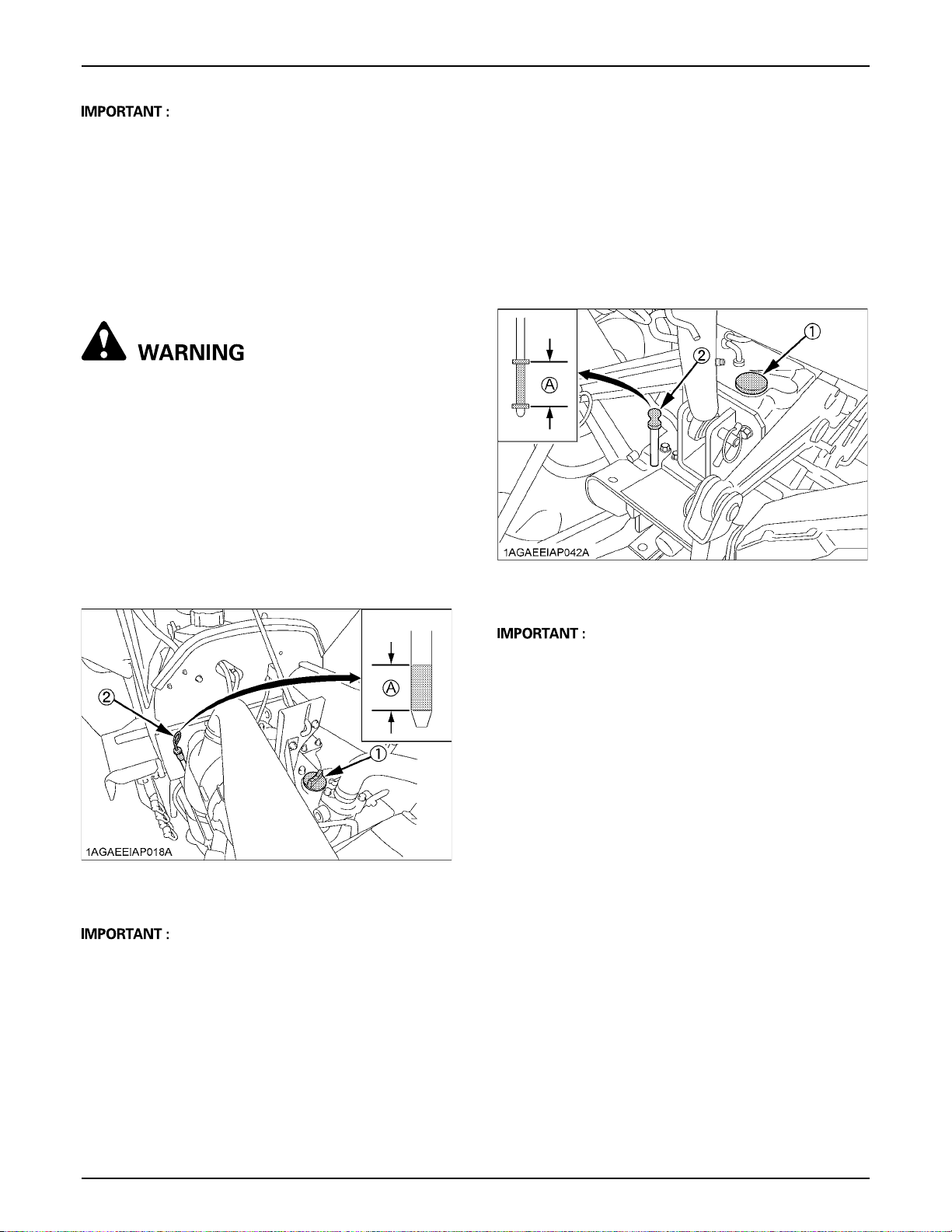
PERIODIC SERVICE52
A Do not permit dirt or trash to get into the fuel system.
A Be careful not to let the fuel tank become empty,
otherwise air will enter the fuel system, necessitating
bleeding before next engine start.
A Be careful not to spill during refueling. If you should
spill, wipe it off at once, or it may cause a fire.
A To prevent condensation (water) accumulation in the
fuel tank, fill the tank before parking overnight.
BChecking Engine Oil Level
To avoid personal injury or death:
A Be sure to stop the engine before checking the
oil level.
1. Park the machine on a flat surface.
2. Check engine oil before starting the engine or 5
minutes or more after the engine has stopped.
3. To check the oil level, draw out the dipstick, wipe it
clean, replace it, and draw it out again. Check to see
that the oil level lies within the crosshatched area.
If the level is too low, add new oil to the prescribed
level at the oil inlet.
(See "LUBRICANTS" in "MAINTENANCE" section.)
BChecking Transmission Fluid Level
1. Park the machine on a flat surface, lower the
implement and shut off engine.
2. To check the oil level, draw out the dipstick, wipe it
clean, replace it, and draw it out again. Check to see
that the oil level lies within the crosshatched area.
If the level is too low, add new oil to the prescribed
level at the oil inlet.
(See "LUBRICANTS" in "MAINTENANCE" section.)
(1) Oil inlet
(2) Dipstick
(A) Oil level is acceptable within this range
(1) Oil inlet
(2) Dipstick
(A) Oil level is acceptable within this range
A When using an oil of different maker or viscosity from
the previous one, remove all of the old oil.
Never mix two different types of oil.
A If oil level is low, do not run engine.
A If oil level is low, do not run engine.
Page 71
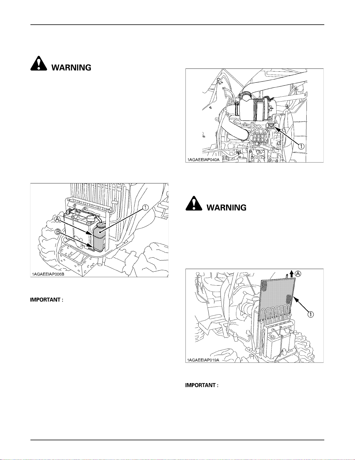
53PERIODIC SERVICE
BChecking Coolant Level
To avoid personal injury or death:
A Do not remove radiator cap while coolant is
hot. When cool, slowly rotate cap to the first
stop and allow sufficient time for excess
pressure to escape before removing the cap
completely.
1. Check to see that the coolant level is between the
"FULL" and "LOW" marks of recovery tank.
2. When the coolant level drops due to evaporation, add
soft water only up to the full level.
In case of leakage, add anti-freeze and soft water in
the specified mixing ratio up to the full level.
(See "Flushing Cooling System and Changing
Coolant" in "EVERY 2 000 HOURS or 2 YEARS" in
"PERIODIC SERVICE" section.)
BCleaning Evacuator Valve
Open the evacuator valve to get rid of large particles of
dust and dirt.
(1) Evacuator valve
BCleaning Grill and Radiator Screen
To avoid personal injury or death:
A Be sure to stop the engine and remove the key
before removing the screen.
(1) Recovery tank (A) "FULL"
(B) "LOW"
A If the radiator cap has to be removed, follow the
caution above and securely retighten the cap.
A Use clean, fresh soft water and anti-freeze to fill the
recovery tank.
A If water should leak, consult your local KUBOTA
Dealer.
1. Check front grill and side screens to be sure they are
clean of debris.
2. Detach the screen and remove all foreign material and
clean the front of radiator completely.
(1) Radiator screen (A) "DETACH"
A Grill and screen must be clean from debris to prevent
engine from overheating and to allow good air intake
for the air cleaner.
Page 72

PERIODIC SERVICE54
BChecking Brake Pedal
1. Inspect the brake pedals for free travel, and smooth
operation.
2. Adjust if incorrect measurement is found:
(See "Adjusting Brake Pedal" in "EVERY 100 HOURS"
in "PERIODIC SERVICE" section.)
BChecking Gauges, Meter and Easy
Checker (TM)
1. Inspect the instrument panel for broken gauge(s),
meter(s) and Easy Checker (TM).
2. Replace if broken.
BChecking Head Light, Hazard Light etc.
1. Inspect the lights for broken bulbs and lenses.
2. Replace if broken.
BChecking Seat Belt and ROPS
1. Always check condition of seat belt and ROPS
attaching hardware before operating tractor.
2. Replace if damaged.
BChecking and Cleaning of Electrical
Wiring and Battery Cables
To avoid personal injury or death:
A A loosened terminal or connector, or damaged
wire may affect the performance of electrical
components or cause short circuits. Leakage
of electricity could result in a fire hazard, a
dead battery or damage to electrical
components.
A Replace damaged wires or connections
promptly.
A If a fuse blows soon after replacement, DO NOT
USE A LARGER THAN RECOMMENDED FUSE
OR BYPASS THE FUSE SYSTEM.
A Many wiring connections are protected by
waterproof plugs, plug and unplug these
connections carefully and make sure they are
sealed correctly after assembly.
A Accumulation of dust, chaff or spilled fuel
deposits around the battery, electrical wiring,
engine or exhaust system are a fire hazard.
CLEAN THESE AREAS BEFORE STARTING
WORK.
To avoid premature electrical malfunctions DO
NOT APPLY high pressure water directly to
battery, wiring, connectors, electrical
components or instrument panel.
Inspect the following Regularly:
1. Check wiring for chafed or cracked insulation.
2. Check wiring harness clamps. Replace if necessary.
3. Check connectors and terminals for looseness,
contamination or overheated (discolored)
connections.
4. Check instrument panel for correct operation of
switches and gauges.
Consult your KUBOTA Dealer regarding maintenance,
diagnosis and repair.
BChecking Movable Parts
If any of the movable parts, such as levers and pedals, is
not smoothly moved because of rust or sticky material, do
not attempt to force it into motion.
In the above case, remove the rust or the sticky material,
and apply oil or grease on the relevant spot.
Otherwise, the machine may get damaged.
Page 73
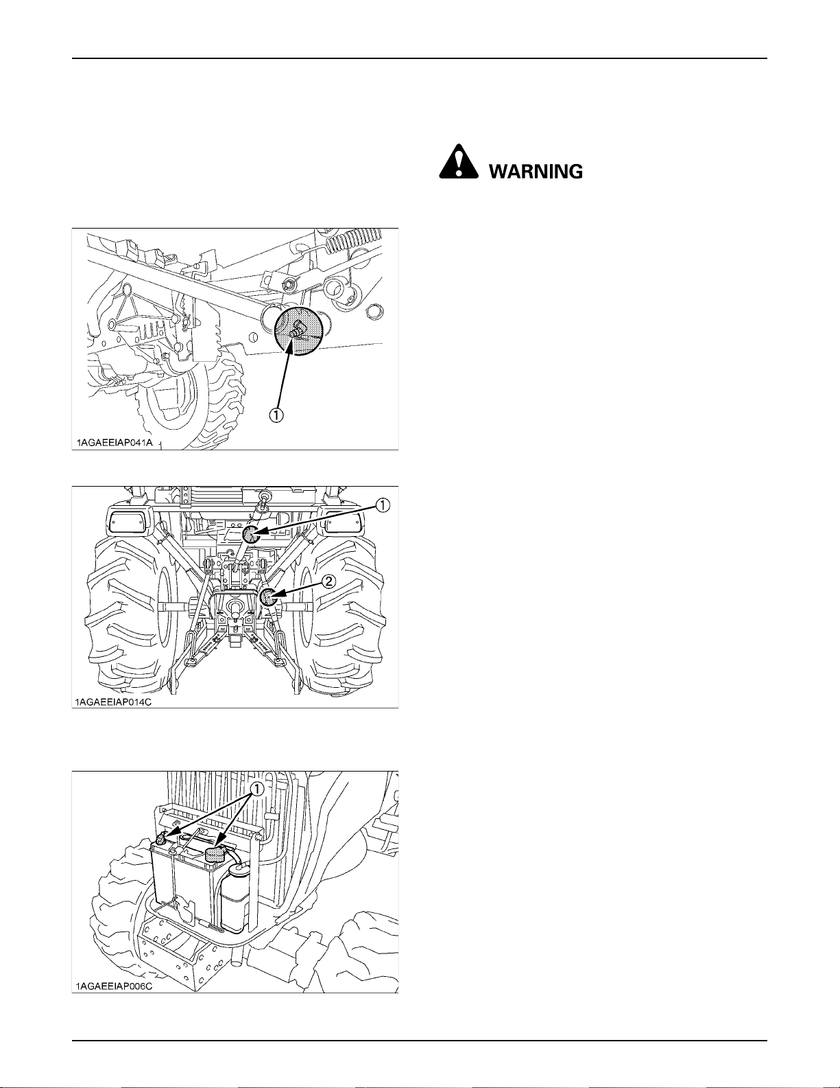
EVERY 50 HOURS
55PERIODIC SERVICE
BLubricating Grease Fittings
Apply a small amount of multipurpose grease to the
following points every 50 hours:
If you operated the machine in extremely wet and muddy
conditions, lubricate grease fittings more often.
(1) Grease fitting (Brake pedals)
BChecking Engine Start System
To avoid personal injury or death:
A Do not allow anyone near the tractor while
testing.
A If the tractor does not pass the test do not
operate the tractor.
A Detach an implement before testing.
C Preparation before testing.
1. Sit on operator's seat.
2. Set the parking brake and stop the engine.
3. Shift the range gear shift lever to "NEUTRAL" position.
4. Place the speed control pedal in "NEUTRAL" position.
5. Shift the PTO clutch lever to "OFF" position.
C Test : Switch for the speed control pedal.
1. Depress the speed control pedal.
2. Turn the key to "START" position.
3. The engine must not crank.
4. If it cranks, consult your local KUBOTA Dealer for this
service.
C Test : Switch for the PTO clutch lever.
1. Place the speed control pedal in "NEUTRAL" position.
2. Shift the PTO clutch lever to "ON" position.
3. Turn the key to "START" position.
4. The engine must not crank.
5. If it cranks, consult your local KUBOTA Dealer for this
service.
(1) Grease fitting (Top link)
(2) Grease fitting (Lifting rod, right)
(1) Battery terminals
C Test : Switches for the operator's seat and the PTO
clutch lever.
1. Sit on the operator's seat.
2. Start the engine.
3. Engage the PTO clutch lever.
4. Stand up. (Do not get off the machine.)
5. The engine must shut off after approximately 1
second.
6. If it does not stop, consult your local KUBOTA Dealer
for this service.
Page 74
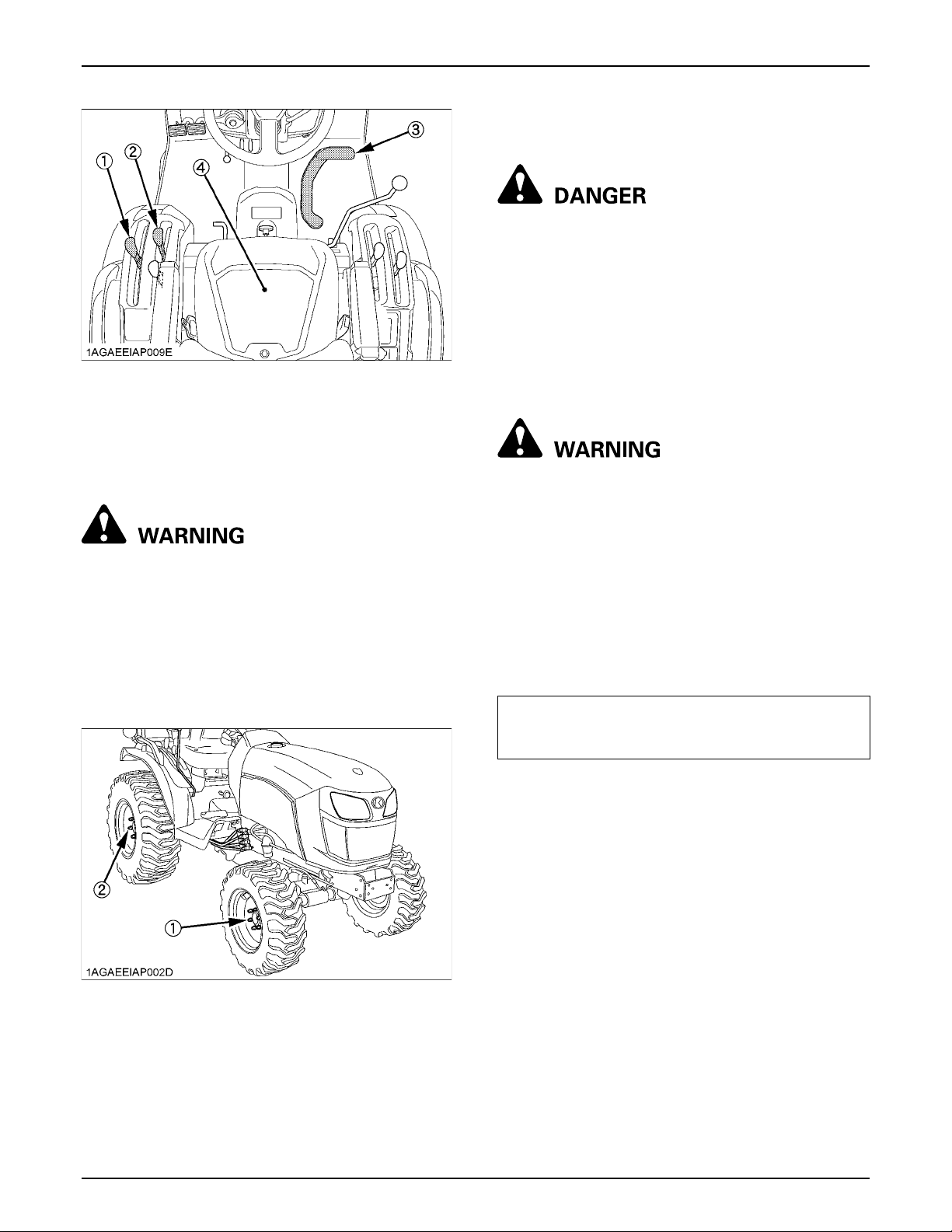
PERIODIC SERVICE56
(1) Range gear shift lever (L-M-H)
(2) PTO clutch lever
(3) Speed control pedal
(4) Operator's seat
BChecking Wheel Bolt Torque
To avoid personal injury or death:
A Never operate tractor with a loose rim, wheel,
or axle.
A Any time bolts and nuts are loosened, retighten
to specified torque.
A Check all bolts and nuts frequently and keep
them tight.
EVERY 100 HOURS
BChecking Battery Condition
To avoid the possibility of battery explosion:
For the refillable type battery, follow the
instructions below.
A Do not use or charge the refillable type battery
if the fluid level is below the LOWER (lower limit
level) mark. Otherwise, the battery component
parts may prematurely deteriorate, which may
shorten the battery's service life or cause an
explosion. Check the fluid level regularly and
add distilled water as required so that the fluid
level is between the UPPER and LOWER levels.
To avoid personal injury or death:
A Never remove the battery cap while the engine
is running.
A Keep electrolyte away from eyes, hands and
clothes. If you are spattered with it, wash it
away completely with water immediately and
get medical attention.
A Keep open sparks and flames away from the
battery at all times. Hydrogen gas mixed with
oxygen becomes very explosive.
A Wear eye protection and rubber gloves when
working around battery.
Check wheel bolts and nuts regularly especially when
new. If they are loose, tighten them as follows.
(1) 79 to 92 N-m (8.1 to 9.4 kgf-m, 58.3 to 67.9 ft-lbs.)
(2) 145 to 150 N-m (14.8 to 15.3 kgf-m, 107.0 to 110.6 ft-lbs.)
The factory-installed battery is of non-refillable
type. If the indicator turns white, do not charge the
battery but replace it with new one.
Mishandling the battery shortens the service life and adds
to maintenance costs.
The original battery is maintenance free, but needs some
servicing.
If the battery is weak, the engine will be difficult to start
and the lights will be dim. It is important to check the
battery periodically.
Page 75
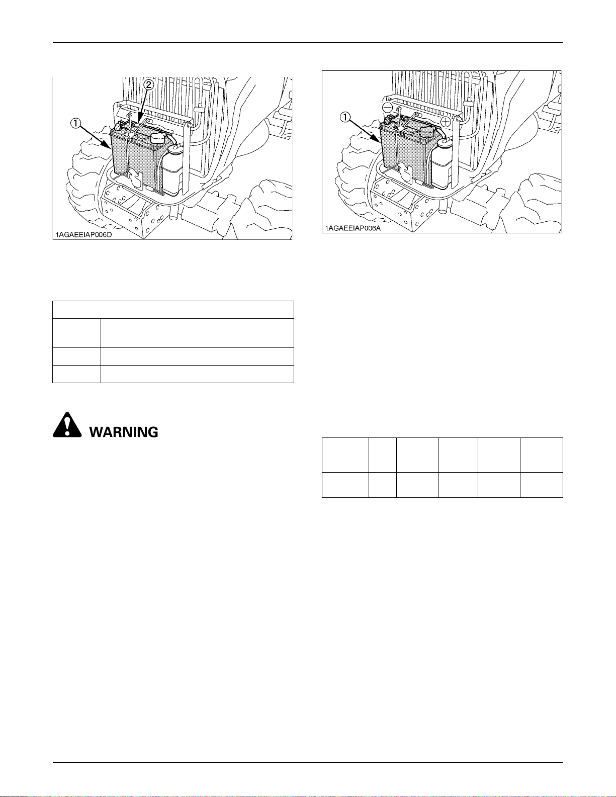
57PERIODIC SERVICE
(1) Battery
(2) Indicator
C How to read the indicator
Check the battery condition by reading the indicator.
State of indicator display
Green
Specific gravity of electrolyte and quality of
electrolyte are both in good condition.
Black Needs charging battery.
White Needs replacing battery.
C Battery Charging
To avoid personal injury or death:
A When the battery is being activated, hydrogen
and oxygen gases in the battery are extremely
explosive. Keep open sparks and flames away
from the battery at all times, especially when
charging the battery.
A When charging the battery, ensure the vent
caps are securely in place (if equipped).
A When disconnecting the cable from the battery,
start with the negative terminal first.
When connecting the cable to the battery, start
with the positive terminal first.
A Never check battery charge by placing a metal
object across the posts.
Use a voltmeter or hydrometer.
(1) Battery
1. To slow charge the battery, connect the battery
positive terminal to the charger positive terminal and
the negative to the negative, then recharge in the
standard fashion.
2. A boost charge is only for emergencies. It will partially
charge the battery at a high rate and in a short time.
When using a boost-charged battery, it is necessary to
recharge the battery as early as possible.
Failure to do this will shorten the battery's service life.
3. The battery is charged if the indicator display turns
green from black.
4. When exchanging an old battery for a new one, use
battery of equal specification shown in table 1.
[TABLE 1]
Battery
Type
55B24L(S)-
MF
Capacity
Volts
(V)
5 hr (Ah)
12 36 80 430 4.5
Reserve
at
Capacity
(min)
Cold
Cranking
Amps (A)
Normal
Charging
Rate (A)
C Direction for Storage
1. When storing the tractor for a long period, remove the
battery from tractor, adjust the electrolyte to the proper
level and store in a dry place out of direct sunlight.
2. The battery self-discharges while it is stored.
Recharge it once every 3 months in hot seasons and
once every 6 months in cold seasons.
Page 76
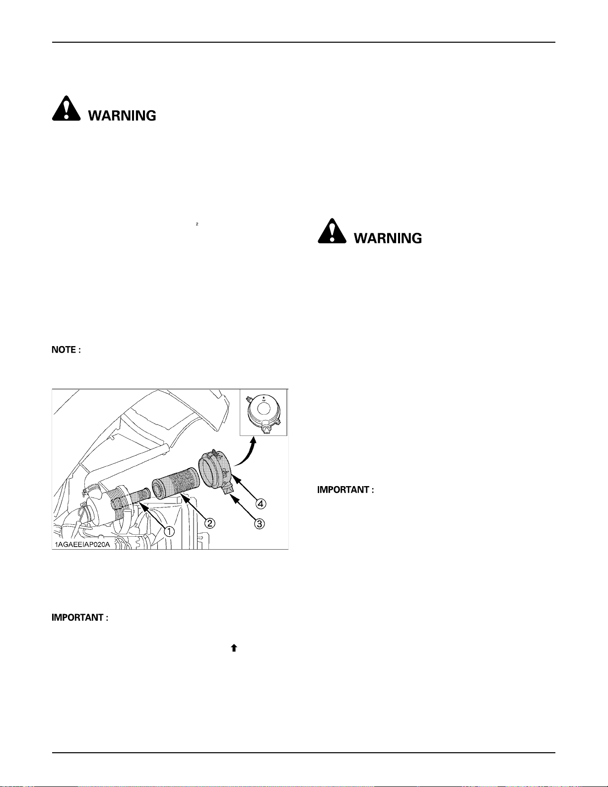
PERIODIC SERVICE58
BCleaning Air Cleaner Primary Element
To avoid personal injury or death:
A Be sure to stop the engine and remove the key
before cleaning air filter element.
1. Remove the air cleaner cover and primary element.
2. Clean the primary element:
(1) When dry dust adheres to the element, blow
compressed air from the inside, turning the
element. Pressure of compressed air must be
under 205 kPa (2.1 kgf/cm , 30 psi).
(2) When carbon or oil adheres to the element, soak
the element in detergent for 15 minutes then wash
it several times in water, rinse with clean water
and dry it naturally. After element is fully dried,
inspect inside of the element with a light and
check if it is damaged or not.
3. Replace air cleaner primary element:
Every 1000 hours or once yearly cleaning, whichever
comes first.
A Do not touch the secondary element except in cases
where replacing is required.
(See "Replacing Air Cleaner Primary Element and
Secondary Element" in "EVERY 1000 HOURS or 1
YEAR" in "PERIODIC SERVICE" section.)
C Evacuator Valve
Open the evacuator valve once a week under ordinary
conditions - or daily when used in a dusty place - to get rid
of large particles of dust and dirt.
BCleaning Fuel Filter
To avoid personal injury or death:
A Stop the engine and remove the key before
checking fuel lines and fuel filter.
A Check the fuel lines periodically. The fuel lines
are subject to wear and aging. Fuel may leak
out onto the running engine, causing a fire.
A Protect your hands when using kerosene to
clean components.
A Check to see if the evacuator valve is blocked with
dust.
(1) Secondary (safety) element
(2) Primary element
(3) Evacuator valve
(4) Cover
A The air cleaner uses a dry element, never apply oil.
A Do not run the engine with filter element removed.
A Be sure to refit the cover with the arrow (on the rear
of cover) upright. If the cover is improperly fitted,
evacuator valve will not function and dust will adhere
to the element.
This job should not be done in the field, but in a clean
place.
1. Loosen and remove the filter bowl, and rinse the inside
with kerosene.
2. Take out the element and dip it in the kerosene to
rinse.
3. After cleaning, reassemble the fuel filter, keeping out
dust and dirt.
4. Bleed the fuel system.
(See "SERVICE AS REQUIRED" in "PERIODIC
SERVICE" section.)
A When the fuel filter bowl has been removed, fuel stops
flowing from the fuel tank. If the fuel tank is almost full,
however, the fuel will flow back from the fuel return
pipe to the fuel filter. Before checking, make sure the
fuel tank is less than half-full.
Page 77
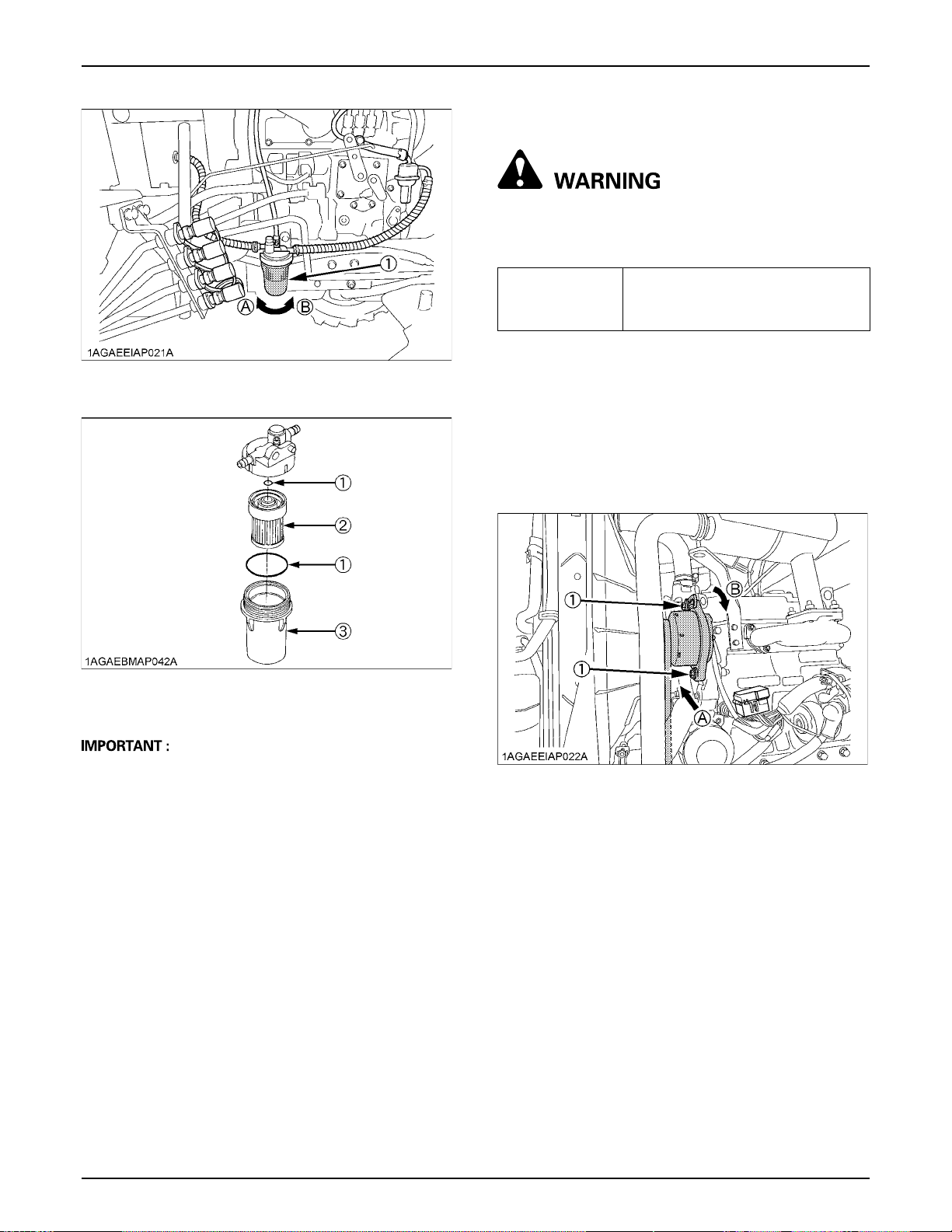
BAdjusting Fan Belt Tension
To avoid personal injury or death:
A Be sure to stop the engine and set the parking
brake before checking belt tension.
59PERIODIC SERVICE
(1) Fuel filter bowl (A) "LOOSEN"
(B) "TIGHTEN"
(1) O ring
(2) Filter element
(3) Filter bowl
Proper fan belt
tension
A deflection of between 7 to 9 mm
(0.28 to 0.35 in.) when the belt is
pressed in the middle of the span.
1. Stop the engine, set the parking brake, and remove
the key.
2. Apply moderate thumb pressure to belt between
pulleys.
3. If tension is incorrect, loosen the alternator mounting
bolts and, using a lever placed between the alternator
and the engine block, pull the alternator out until the
deflection of the belt falls within acceptable limits.
4. Replace fan belt if it is damaged.
A If dust, dirt or water enters the fuel system, the fuel
pump and injection nozzles are subject to premature
wear. To prevent this, be sure to clean the fuel filter
bowl and element periodically.
(1) Bolt (A) Check the belt tension
(B) To tighten
Page 78
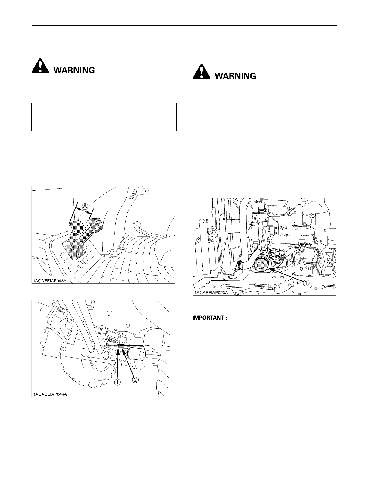
PERIODIC SERVICE60
BAdjusting Brake Pedal
To avoid personal injury or death:
A Stop the engine and chock the wheels before
checking brake pedal.
Proper brake pedal
free travel
1. Release the parking brake.
2. Slightly depress the brake pedals and measure free
travel at the top of pedal stroke.
3. If adjustment is needed, loosen the lock nut and turn
the turnbuckle to adjust the rod length within
acceptable limits.
4. Retighten the lock nut.
30 to 40 mm on the pedal
Keep the free travel in the right
and left brake pedals equal.
EVERY 200 HOURS
BReplacing Engine Oil Filter
To avoid personal injury or death:
A Be sure to stop the engine before changing the
oil filter cartridge.
A Allow engine to cool down sufficiently, oil can
be hot and can burn.
1. Remove the oil filter.
2. Put a film of clean engine oil on the rubber seal of the
new filter.
3. Tighten the filter quickly until it contacts the mounting
surface.
Tighten filter by hand an additional 1/2 turn only.
4. After the new filter has been replaced, the engine oil
normally decreases a little. Make sure that the engine
oil does not leak through the seal and be sure to check
the oil level on the dipstick. Then, replenish the engine
oil up to the prescribed level.
(1) Lock nut (Both sides)
(2) Turnbuckle (Both sides)
(A) Free travel
(1) Engine oil filter
A To prevent serious damage to the engine, use only a
KUBOTA genuine filter.
Page 79
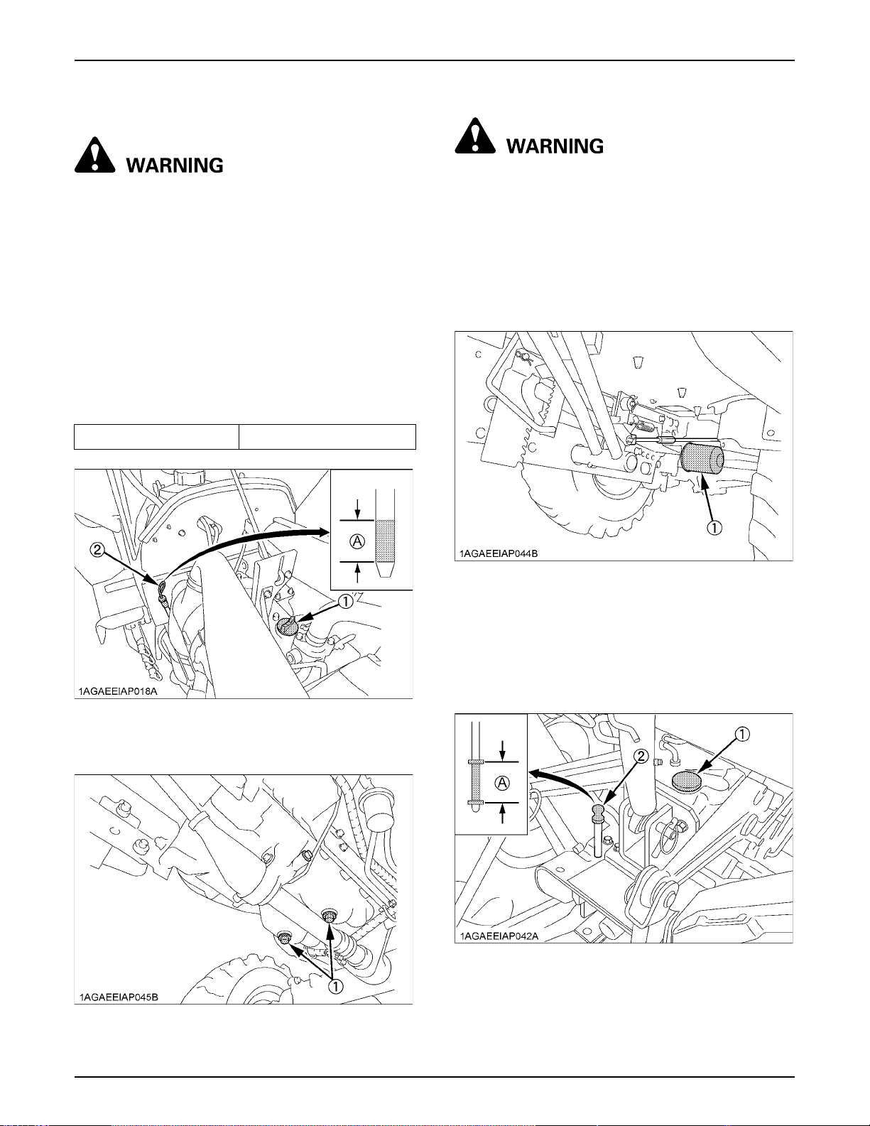
BChanging Engine Oil
To avoid personal injury or death:
A Be sure to stop the engine before changing the
oil.
A Allow engine to cool down sufficiently, oil can
be hot and can burn.
1. To drain the used oil, remove the drain plug at the
bottom of the engine and drain the oil completely into
the oil pan.
All the used oil can be drained out easily when the
engine is still warm.
2. After draining reinstall the drain plug.
3. Fill with the new oil up to the upper line on the dipstick.
(See "LUBRICANTS, FUEL AND COOLANT" in
"MAINTENANCE" section.)
Oil capacity with filter 3.1 L (3.3 U.S.qts.)
61PERIODIC SERVICE
BReplacing Transmission Oil Filter [HST]
To avoid personal injury or death:
A Be sure to stop the engine before changing the
oil filter cartridge.
A Allow engine to cool down sufficiently, oil can
be hot and can burn.
1. Place the oil pan underneath the transmission oil filter
and remove the filter.
Do not remove the hydraulic oil filter. Otherwise, the oil
comes out.
(1) Oil inlet
(2) Dipstick
(A) Oil level is acceptable within this range
(1) Transmission oil filter [HST]
2. Put a film of clean transmission oil on the rubber seal
of the new filter.
3. Quickly tighten the filter until it contacts the mounting
surface, then, with a filter wrench, tighten it an
additional 1 turn only.
4. After the new filter has been replaced, fill the
transmission oil up to the upper limit on the dipstick.
(1) Oil inlet
(2) Dipstick
(A) Oil level is acceptable within this range
(1) Drain plug (both sides)
5. After running the engine for a few minutes, stop the
engine and check the oil level again, add oil to the
prescribed level.
Page 80
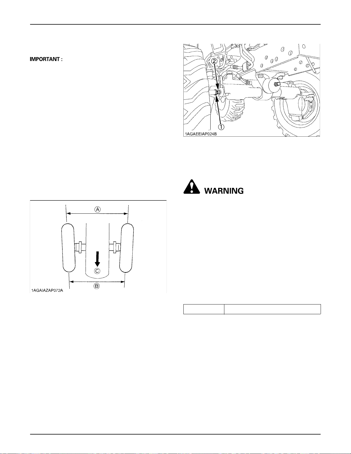
PERIODIC SERVICE62
6. Make sure that the transmission fluid doesn't leak past
the seal on the filter.
A To prevent serious damage to the hydraulic system,
use only a KUBOTA genuine filter.
A Do not operate the tractor immediately after changing
the transmission fluid.
Run the engine at medium speed for a few minutes to
prevent damage to the transmission.
BAdjusting Toe-in
1. Park tractor on a flat place.
2. Turn steering wheel so front wheels are in the straight
ahead position.
3. Lower the implement, lock the park brake and stop the
engine.
4. Measure distance between tire beads at front of tire,
hub height.
5. Measure distance between tire beads at rear of tire,
hub height.
6. Front distance should be 0 to 10 mm (0 to 3/8 in.) less
than rear distance. If not, adjust tie rod length.
(1) Tie-rod nut
(2) Tie-rod joint
EVERY 400 HOURS
BChanging Transmission Fluid
To avoid personal injury or death:
A Allow engine to cool down sufficiently, oil can
be hot and can burn.
(A) Wheel - to - wheel distance at rear
(B) Wheel - to - wheel distance at front
(C) "FRONT"
C Adjusting procedures
1. Loosen the tie-rod nut.
2. Turn the tie-rod joint to adjust the rod length until the
proper toe-in measurement is obtained.
3. Retighten the tie-rod nut.
1. To drain the used oil, remove the drain plug at the
bottom of the transmission case and drain the oil
completely into the oil pan.
2. After draining reinstall the drain plug.
3. Fill with new KUBOTA SUPER UDT fluid up to the
upper limit on the dipstick.
(See "LUBRICANTS" in "MAINTENANCE" section
and "DAILY CHECK" in "PERIODIC SERVICE"
section)
4. After running the engine for a few minutes, stop it and
check the oil level again; add oil to prescribed level.
5. Properly dispose of used oil.
Oil capacity 15 L (4.0 U.S.gals.)
Page 81
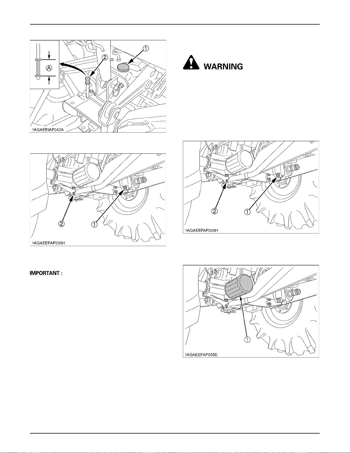
(1) Oil inlet
(2) Dipstick
63PERIODIC SERVICE
BReplacing Hydraulic Oil Filter
To avoid personal injury or death:
A Be sure to stop the engine before changing the
oil filter cartridge.
A Allow engine to cool down sufficiently, oil can
be hot and can burn.
1. Remove the drain plugs at the bottom of the
transmission case and drain the oil completely into the
oil pan.
2. After draining reinstall the drain plugs.
(A) Oil level is acceptable within this range
(1) Drain plug
(2) Drain plugs (Both sides)
A If the 3-point hitch can not be raised by setting the
hydraulic control lever to the UP position after long
term storage or when changing the transmission oil,
turn steering wheel to the right and left several times
to bleed air from the system.
A Do not operate the tractor immediately after changing
the transmission fluid.
(1) Drain plug
(2) Drain plug (Both sides)
3. Remove the oil filter.
(1) Hydraulic oil filter
4. Put a film of clean transmission oil on the rubber seal
of the new filter.
5. Quickly tighten the filter until it contacts the mounting
surface, then tighten it by hand an additional 1/2 turn
only.
6. After the new filter has been replaced, fill the
transmission oil up to the upper limit on the dipstick.
Page 82
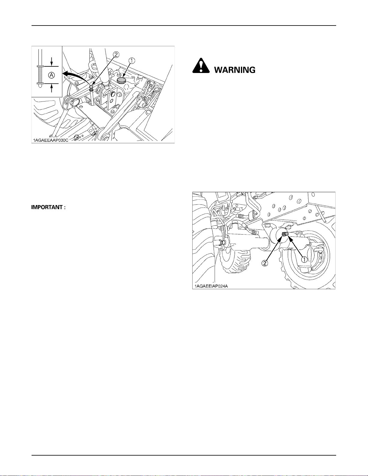
PERIODIC SERVICE64
(1) Oil inlet
(2) Dipstick
7. After running the engine for a few minutes, stop the
engine and check the oil level again, add oil to the
prescribed level.
8. Make sure that the transmission fluid doesn't leak past
the seal on the filter.
(A) Oil level is acceptable within this range
BAdjusting Front Axle Pivot [4WD]
To avoid personal injury or death:
A Park the tractor on a flat place.
A Lower the implement, lock the parking brake
and stop the engine.
If the front axle pivot pin adjustment is not correct, front
wheel vibration can occur causing vibration in the steering
wheel.
C Adjusting procedure
Loosen the lock nut, and tighten the adjusting screw so
that the oscillating load is 50 to 100 N (5.1 to 10.2 kgf, 11.2
to 22.5 lbf). (If the adjusting screw is tightened, loosened
and retightened, apply liquid gasket to its tip.) Retighten
the lock nut.
Consult your local KUBOTA Dealer for further details.
A To prevent serious damage to the hydraulic system,
use only a KUBOTA genuine filter.
(1) Adjusting screw
(2) Lock nut
BReplacing Fuel Filter Element
(See "Cleaning Fuel Filter" in "EVERY 100 HOURS" in
"PERIODIC SERVICE" section.)
Page 83
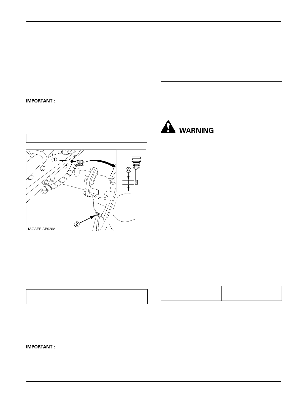
65PERIODIC SERVICE
BChanging Front Axle Case Oil
1. Park the tractor on a firm, flat and level surface.
2. To drain the used oil, remove the right and left drain
plugs and filling plug at the front axle case and drain
the oil completely into the oil pan.
3. After draining, reinstall the drain plugs.
4. Fill with new oil up to the upper notch on the dipstick.
(See "LUBRICANTS, FUEL AND COOLANT" in
"MAINTENANCE" section.)
A After 10 minutes, check the oil level again; add oil to
prescribed level.
5. After filling, reinstall the filling plug.
6. Properly dispose of used oil.
Oil capacity 3.5 L (3.7 U.S.qts.)
(1) Filling plug with dipstick
(2) Drain plug
(A) Oil level is acceptable
within this range
EVERY 800 HOURS
BAdjusting Engine Valve Clearance
Consult your local KUBOTA Dealer for this service.
EVERY 1000 HOURS or 1 YEAR
Be sure to do the following servicing once every 1000
hours or yearly, whichever comes first.
EVERY 1 500 HOURS
BChecking Fuel Injection Nozzle Injection
Pressure
Consult your local KUBOTA Dealer for this service.
EVERY 2000 HOURS or 2 YEARS
Be sure to do the following servicing once every 2000
hours or biennially, whichever comes first.
BFlushing Cooling System and Changing
Coolant
To avoid personal injury or death:
A Do not remove radiator cap while coolant is
hot. When cool, slowly rotate cap to the first
stop and allow sufficient time for excess
pressure to escape before removing the cap
completely.
1. Stop the engine, remove the key and let it cool down.
2. To drain the coolant, disconnect the radiator hose
(engine side), and remove the radiator cap. The
radiator cap must be removed to completely drain the
coolant. Use the drip pan to catch coolant.
3. After all coolant is drained, reconnect the radiator
hose.
4. Fill with clean soft water and cooling system cleaner.
5. Follow directions of the cleaner instruction.
6. After flushing, fill with clean soft water and anti-freeze
until the coolant level is just below the radiator cap.
Install the radiator cap securely.
7. Fill with coolant up to the "FULL" mark of recovery
tank.
8. Start and operate the engine for few minutes.
9. Stop the engine, remove the key and let cool.
10.Check coolant level of recovery tank and add coolant
if necessary.
11.Properly dispose of used coolant.
Coolant capacity
(with recovery tank)
3.8 L (4.0 U.S.gals.)
BReplacing Air Cleaner Primary Element
and Secondary Element
(See "Cleaning Air Cleaner Primary Element" in "EVERY
100 HOURS" in "PERIODIC SERVICE" section.)
A To prevent serious damage to the engine, use only a
KUBOTA genuine filter.
Page 84
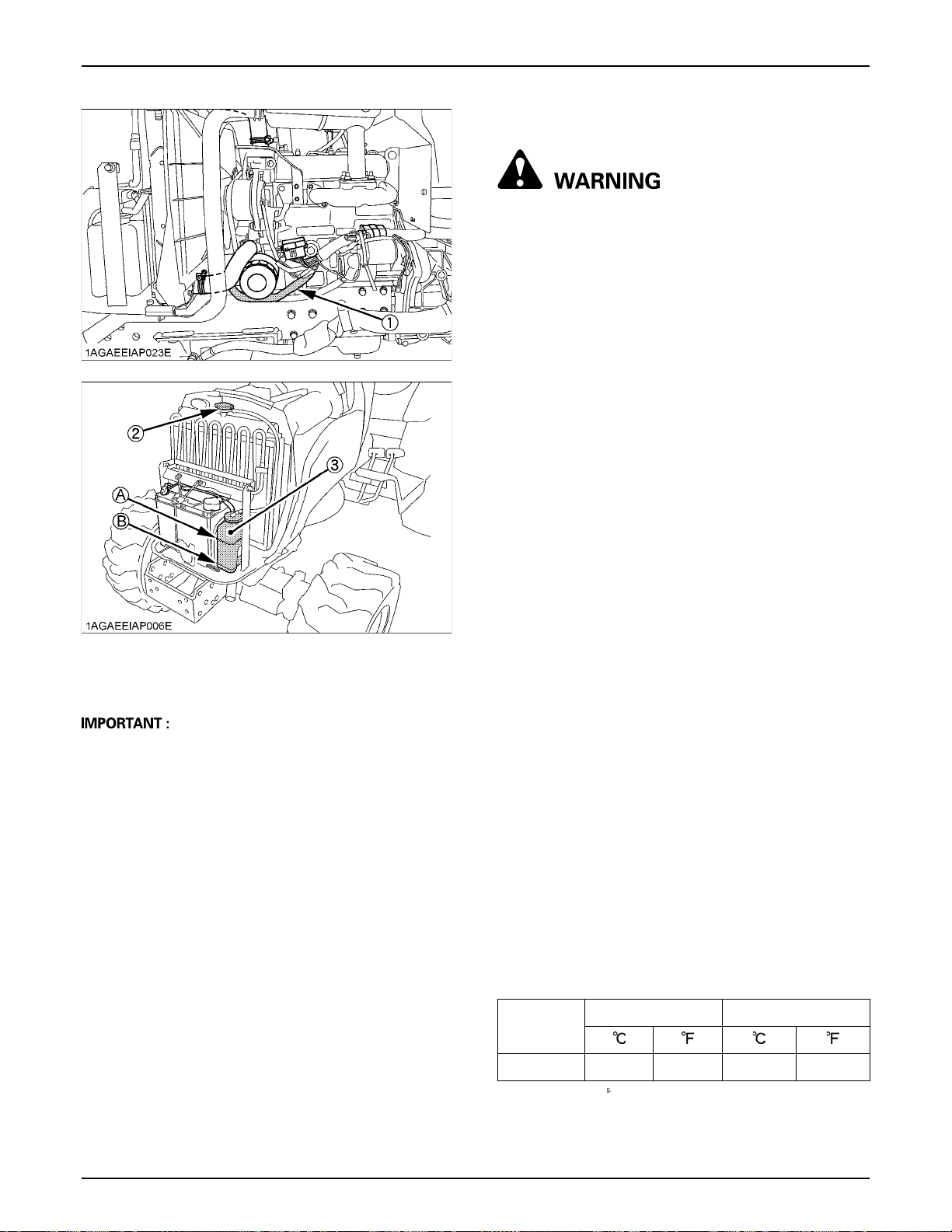
PERIODIC SERVICE66
(1) Radiator hose
(2) Radiator cap
(3) Recovery tank
A Do not start engine without coolant.
A Use clean, fresh soft water and anti-freeze to fill the
radiator and recovery tank.
A When mixing the anti-freeze with water, the anti-freeze
mixing ratio is 50%.
A Securely tighten radiator cap. If the cap is loose or
improperly fitted, water may leak out and the engine
could overheat.
(A) "FULL"
(B) "LOW"
BAnti-Freeze
To avoid personal injury or death:
A When using antifreeze, put on some protection
such as rubber gloves. (Antifreeze contains
poison.)
A If it is swallowed, seek immediate medical help.
Do NOT make a person throw up unless told to
do so by poison control or a health care
professional. Use standard first aid and CPR
for signs of shock or cardiac arrest. Call your
local Poison Control Center or your local
emergency number for further assistance.
A When antifreeze comes in contact with the skin
or clothing, wash it off immediately.
A Do not mix different types of Antifreeze.
The mixture can produce chemical reaction
causing harmful substances.
A Antifreeze is extremely flammable and
explosive under certain conditions. Keep fire
and children away from antifreeze.
A When draining fluids from the engine, place
some container underneath the engine body.
A Do not pour waste onto the ground, down a
drain, or into any water source.
A Also, observe the relevant environmental
protection regulations when disposing of
antifreeze.
Always use a 50/50 mix of long-life coolant and clean soft
water in KUBOTA engines.
Consult your local KUBOTA Dealer concerning coolant for
extreme conditions.
1. Long-life coolant (hereafter LLC) comes in several
types. Use ethylene glycol (EG) type for this engine.
2. Before employing LLC-mixed cooling water, fill the
radiator with fresh water and empty it again.
Repeat this procedure 2 or 3 times to clean up the
inside.
3. Mixing the LLC
Premix 50% LLC with 50% clean soft water. When
mixing, stir it up well, and then fill into the radiator.
4. The procedure for the mixing of water and antifreeze
differs according to the make of the antifreeze and the
ambient temperature. Refer to SAE J1034 standard,
more specifically also to SAE J814c.
Vol %
Freezing Point Boiling Point*
Anti-freeze
50 -37 -34 108 226
D At 1.013 x 10 Pa (760mmHg) pressure (atmospheric).
A higher boiling point is obtained by using a radiator
pressure cap which permits the development of
pressure within the cooling system.
Page 85
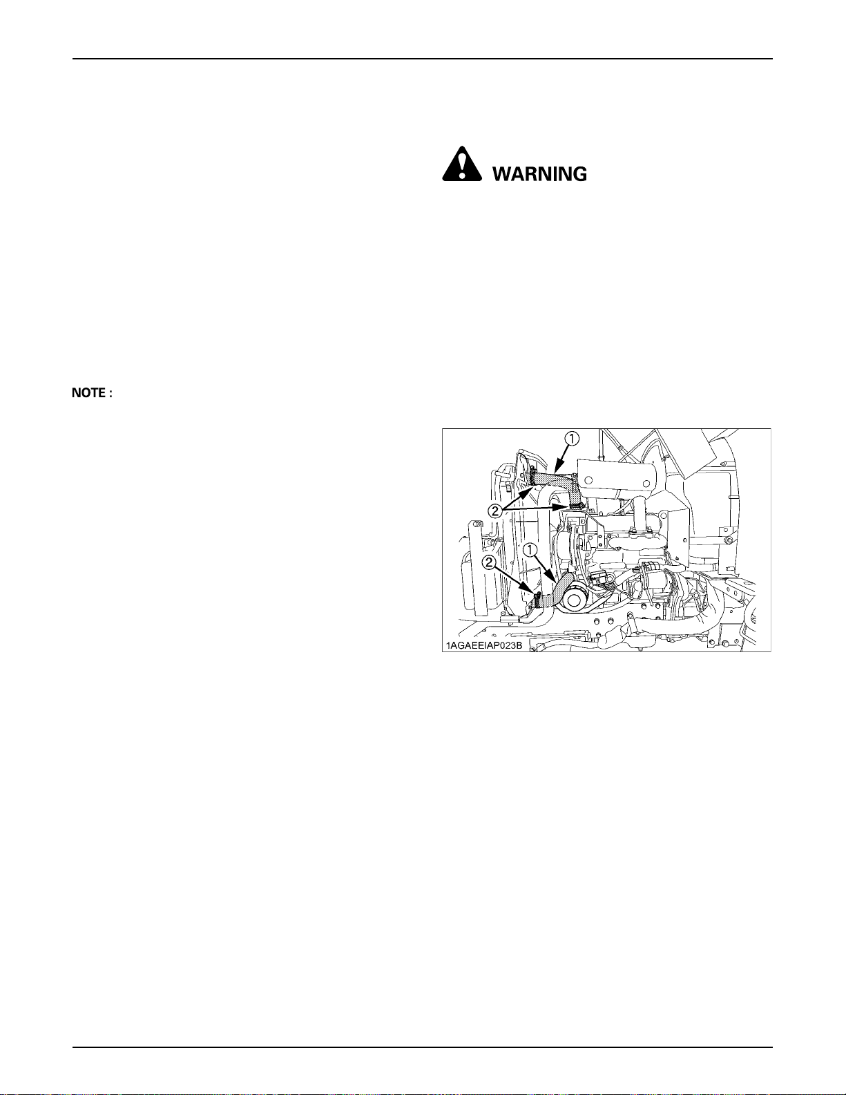
67PERIODIC SERVICE
5. Adding the LLC
(1) Add only water if the mixture reduces in amount
by evaporation.
(2) If there is a mixture leak, add the LLC of the same
manufacturer and type in the same mixture
percentage.
D Never add any long-life coolant of different
manufacturer. (Different brands may have
different additive components, and the engine
may fail to perform as specified.)
6. When the LLC is mixed, do not employ any radiator
cleaning agent. The LLC contains anticorrosive agent.
If mixed with the cleaning agent, sludge may build up,
adversely affecting the engine parts.
7. Kubota's genuine long-life coolant has a service life of
2 years. Be sure to change the coolant every 2000
hours or every 2 years whichever comes faster.
A The above data represent industry standards that
necessitate a minimum glycol content in the
concentrated antifreeze.
EVERY 3 000 HOURS
BChecking Injection Pump
Consult your local KUBOTA Dealer for this service.
EVERY 1 YEAR
BChecking Radiator Hoses and Clamps
To avoid personal injury or death:
A Be sure to stop the engine and remove the key
before checking radiator hose and clamp.
A Allow engine and coolant to cool down
sufficiently before checking.
Inspect every year; replace if any deterioration (crack,
hardening, scar, or deformation) or damage occurred.
1. If hose clamps are loose or water leaks, tighten bands
securely.
2. Replace hoses and tighten hose clamps securely, if
radiator hoses are swollen, hardened or cracked.
Replace hoses and hose clamps every 4 years or earlier
if checked and found that hoses are swollen, hardened or
cracked.
(1) Radiator hoses (2 hoses)
(2) Clamp bands (4 clamps)
BChecking Intake Air Line
1. Check to see that hoses and hose clamps are tight and
not damaged.
2. If hoses and clamps are found worn or damaged,
replace or repair them at once.
Page 86
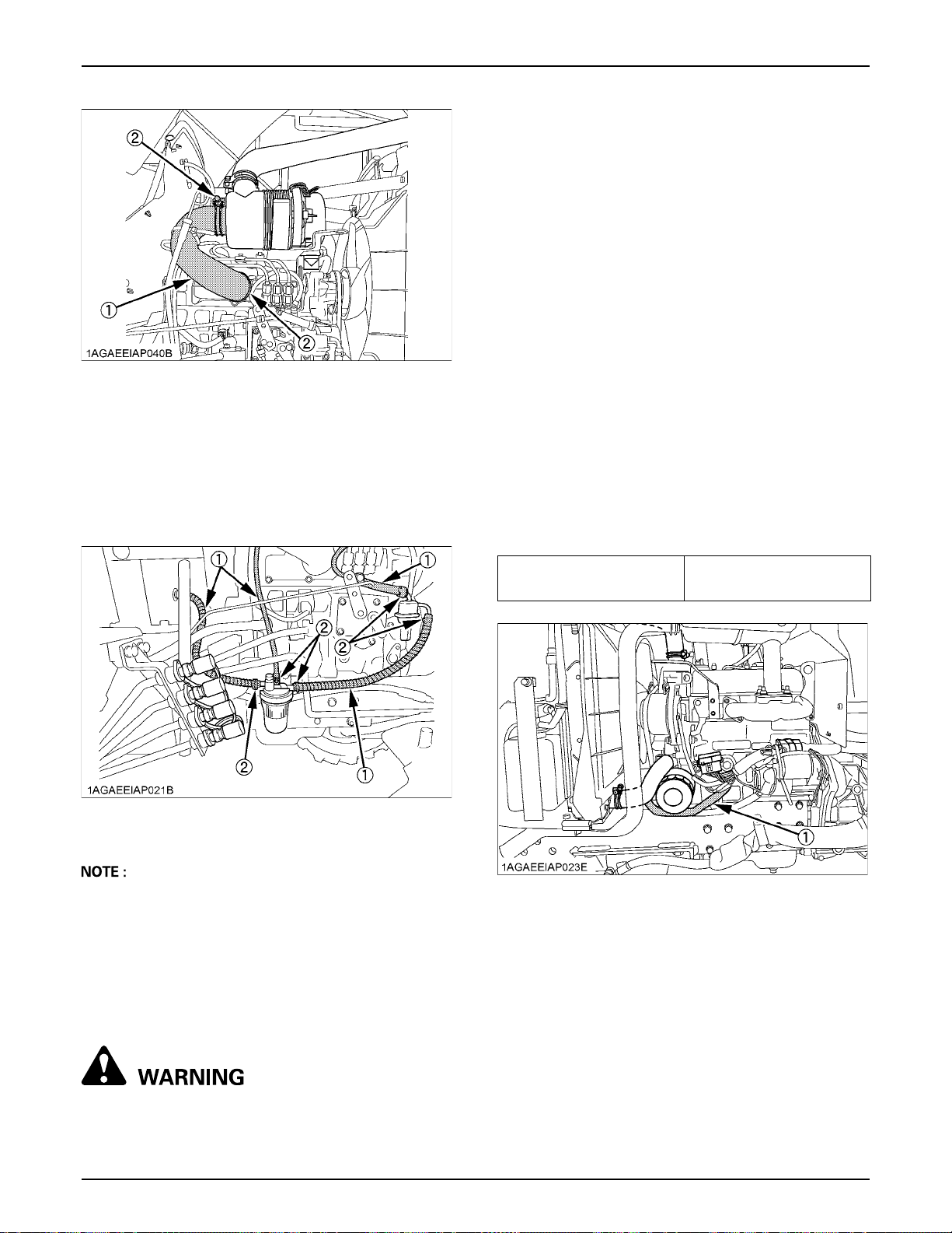
PERIODIC SERVICE68
(1) Hose
(2) Hose clamps
BChecking Fuel Lines
1. Check to see that all lines and hose clamps are tight
and not damaged.
2. If hoses and clamps are found worn or damaged,
replace or repair them at once.
A Do not remove radiator cap while coolant is
hot. When cool, slowly rotate cap to the first
stop and allow sufficient time for excess
pressure to escape before removing the cap
completely.
1. Stop the engine, remove the key and let it cool down.
2. To drain the coolant, disconnect the radiator hose
(engine side), and remove the radiator cap. The
radiator cap must be removed to completely drain the
coolant. Use the drip pan to catch coolant.
3. After all coolant is drained, reconnect the radiator
hose.
4. Fill with clean soft water and cooling system cleaner.
5. Follow directions of the cleaner instruction.
6. After flushing, fill with clean soft water and anti-freeze
until the coolant level is just below the radiator cap.
Install the radiator cap securely.
7. Fill with coolant up to the "FULL" mark of recovery
tank.
8. Start and operate the engine for few minutes.
9. Stop the engine, remove the key and let cool.
10.Check coolant level of recovery tank and add coolant
if necessary.
11.Properly dispose of used coolant.
(1) Fuel lines
(2) Clamp bands
A If the fuel line is removed, be sure to properly bleed the
fuel system.
(See "Bleeding Fuel System" in "SERVICE AS
REQUIRED" in "PERIODIC SERVICE" section.)
EVERY 2 YEARS
BFlushing Cooling System and Changing
Coolant
Coolant capacity
(with recovery tank)
3.8 L (4.0 U.S.gals.)
To avoid personal injury or death:
Page 87
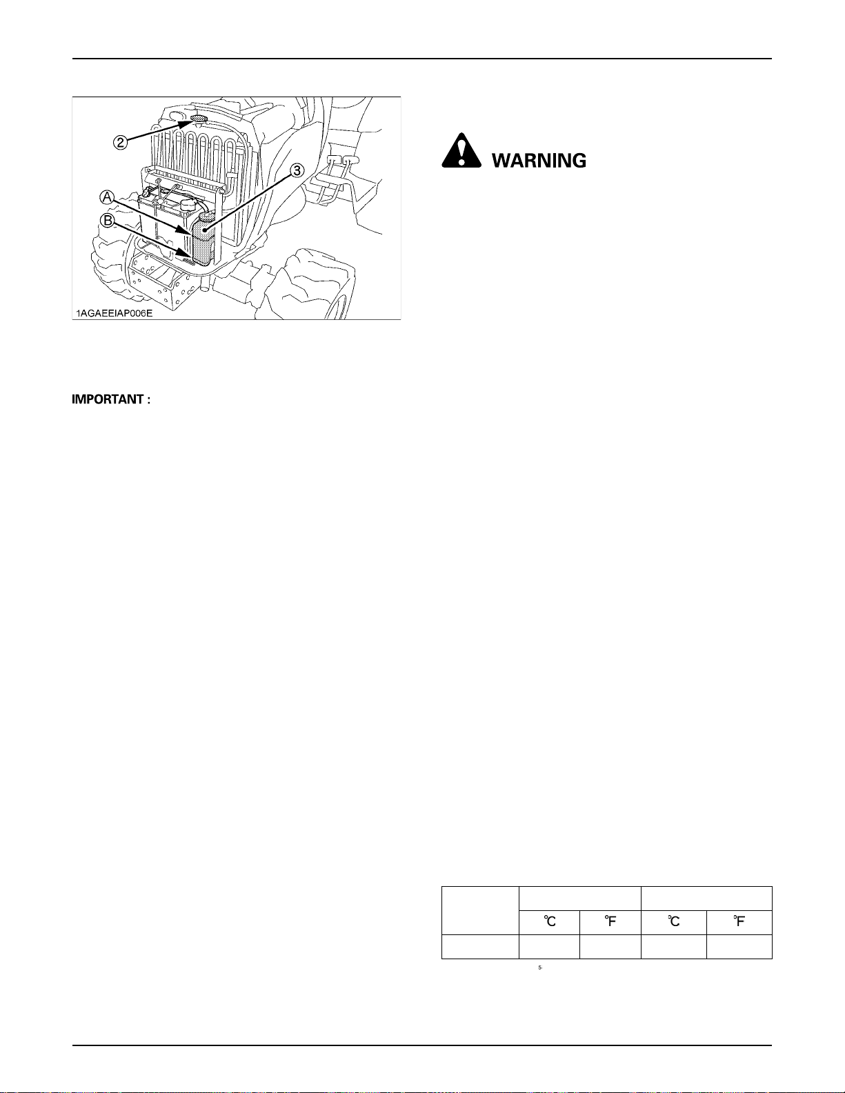
(1) Radiator hose
(2) Radiator cap
(3) Recovery tank
(A) "FULL"
(B) "LOW"
A Do not start engine without coolant.
A Use clean, fresh soft water and anti-freeze to fill the
radiator and recovery tank.
A When mixing the anti-freeze with water, the anti-freeze
mixing ratio is 50%.
A Securely tighten radiator cap. If the cap is loose or
improperly fitted, water may leak out and the engine
could overheat.
69PERIODIC SERVICE
BAnti-Freeze
To avoid personal injury or death:
A When using antifreeze, put on some protection
such as rubber gloves. (Antifreeze contains
poison.)
A If it is swallowed, seek immediate medical help.
Do NOT make a person throw up unless told to
do so by poison control or a health care
professional. Use standard first aid and CPR
for signs of shock or cardiac arrest. Call your
local Poison Control Center or your local
emergency number for further assistance.
A When antifreeze comes in contact with the skin
or clothing, wash it off immediately.
A Do not mix different types of Antifreeze.
The mixture can produce chemical reaction
causing harmful substances.
A Antifreeze is extremely flammable and
explosive under certain conditions. Keep fire
and children away from antifreeze.
A When draining fluids from the engine, place
some container underneath the engine body.
A Do not pour waste onto the ground, down a
drain, or into any water source.
A Also, observe the relevant environmental
protection regulations when disposing of
antifreeze.
Always use a 50/50 mix of long-life coolant and clean soft
water in KUBOTA engines.
Consult your local KUBOTA Dealer concerning coolant for
extreme conditions.
1. Long-life coolant (hereafter LLC) comes in several
types. Use ethylene glycol (EG) type for this engine.
2. Before employing LLC-mixed cooling water, fill the
radiator with fresh water and empty it again.
Repeat this procedure 2 or 3 times to clean up the
inside.
3. Mixing the LLC
Premix 50% LLC with 50% clean soft water. When
mixing, stir it up well, and then fill into the radiator.
4. The procedure for the mixing of water and antifreeze
differs according to the make of the antifreeze and the
ambient temperature. Refer to SAE J1034 standard,
more specifically also to SAE J814c.
Vol %
Freezing Point Boiling Point*
Anti-freeze
50 -37 -34 108 226
D At 1.013 x 10 Pa (760mmHg) pressure (atmospheric).
A higher boiling point is obtained by using a radiator
pressure cap which permits the development of
pressure within the cooling system.
Page 88
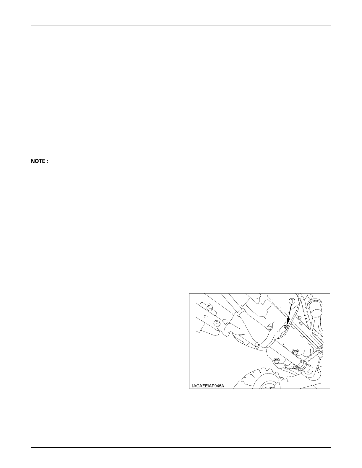
PERIODIC SERVICE70
5. Adding the LLC
(1) Add only water if the mixture reduces in amount
by evaporation.
(2) If there is a mixture leak, add the LLC of the same
manufacturer and type in the same mixture
percentage.
D Never add any long-life coolant of different
manufacturer. (Different brands may have
different additive components, and the engine
may fail to perform as specified.)
6. When the LLC is mixed, do not employ any radiator
cleaning agent. The LLC contains anticorrosive agent.
If mixed with the cleaning agent, sludge may build up,
adversely affecting the engine parts.
7. Kubota's genuine long-life coolant has a service life of
2 years. Be sure to change the coolant every 2 years.
A The above data represent industry standards that
necessitate a minimum glycol content in the
concentrated antifreeze.
BReplacing Radiator Hose (Water pipes)
Replace the hose and clamp.
(See "Checking Radiator Hose and Clamp" in "EVERY
200 HOURS" in "PERIODIC SERVICE" section.)
EVERY 4 YEARS
BReplacing Radiator Hose (Water pipes)
Replace the hoses and clamps.
(See "Checking Radiator Hoses and Clamps" in "EVERY
1 YEAR" in "PERIODIC SERVICE" section.)
BReplacing Fuel Lines
Consult your local KUBOTA Dealer for this service.
BReplacing Intake Air Line
Consult your local KUBOTA Dealer for this service.
SERVICE AS REQUIRED
BBleeding Fuel System
Air must be removed:
1. When the fuel filter or lines are removed.
2. When the tank is completely empty.
3. After the tractor has not been used for a long period of
time.
C Bleeding procedure is as follows:
1. Fill the fuel tank with fuel.
2. Start the engine and run for about 30 seconds, and
then stop the engine.
BReplacing Fuel Hose
Consult your local KUBOTA Dealer for this service.
BReplacing Intake Air Line
Consult your local KUBOTA Dealer for this service.
BDraining Clutch Housing Water
The tractor is equipped with a drain plug under the clutch
housing.
After operating in rain, snow or tractor has been washed,
water may get into the clutch housing.
Remove the drain plug and drain the water, then install the
plug again.
(1) Water drain plug
Page 89
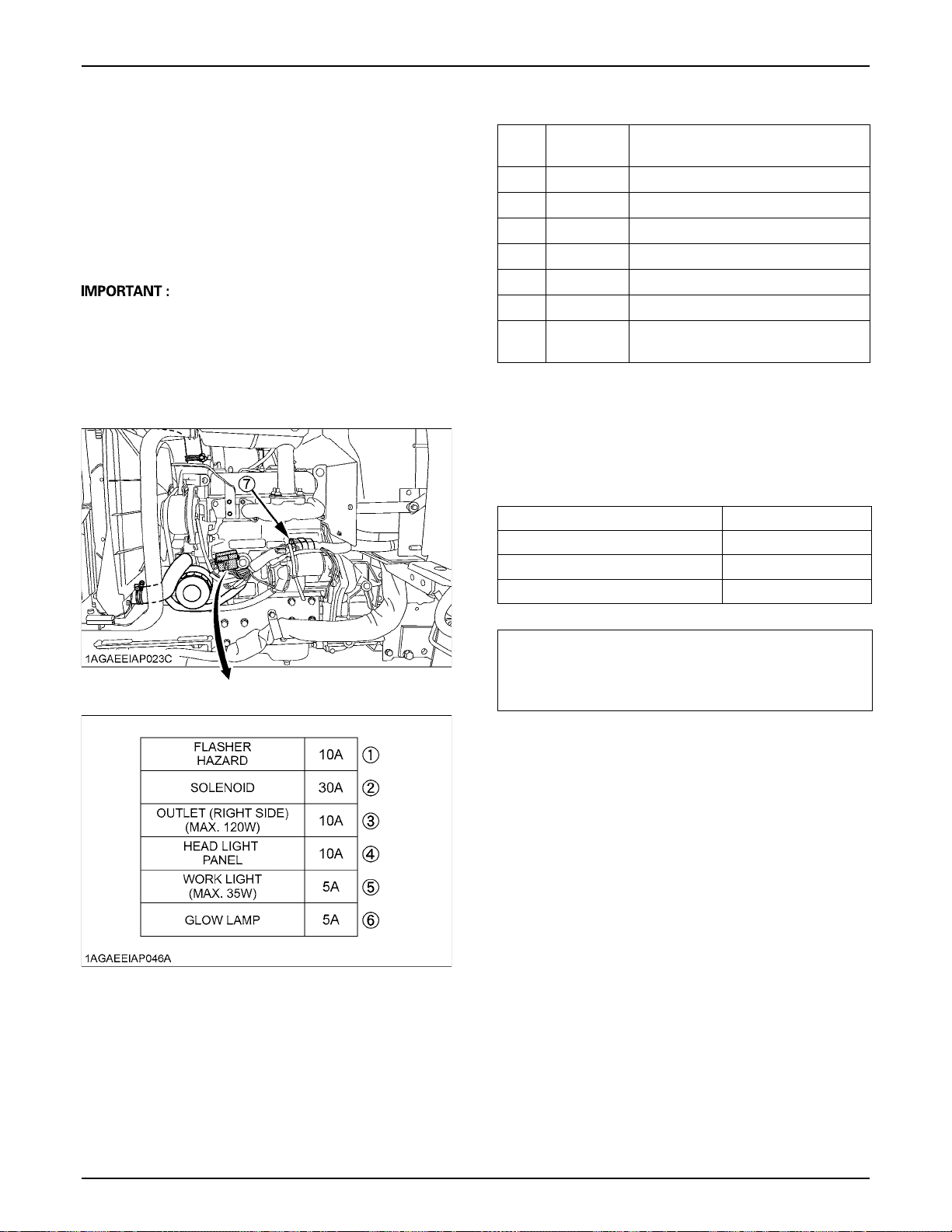
BReplacing Fuse
The tractor electrical system is protected from potential
damage by fuses.
A blown fuse indicates that there is an overload or short
somewhere in the electrical system.
If any of the fuses should blow, replace with a new one of
the same capacity.
A Before replacing a blown fuse, determine why the fuse
blew and make any necessary repairs. Failure to
follow this procedure may result in serious damage to
the tractor electrical system. Refer to the
"TROUBLESHOOTING" section of this manual or your
local KUBOTA Dealer for specific information dealing
with electrical problems.
C Protected circuit
FUSE
CAPACITY
No.
(1) 10 Flasher / Hazard
(2) 30 Solenoid
(3) 10 Outlet (Right side)
(4) 10 Head Light / Panel
(5) 5 Work light
(6) 5 Glow lamp
(7)
(A)
Slow blow
fuse
Check circuit against wrong battery
connection
Protected circuit
BReplacing Light Bulb
1. Head lights
Take the bulb out of the light body and replace with a
new one.
2. Other lights
Detach the lens and replace the bulb.
71PERIODIC SERVICE
Light Capacity
Head light 23 W
Tail light / Turn signal 21 / 5 W
Hazard light / Turn signal 32 CP
Replace the below parts if any deterioration (crack,
hardening, scar or deformation) or damage occurred.
However, must be replaced every 4 years regardless of
the condition.
BReplacing Radiator Hose (Water pipes)
Replace the hoses and clamps.
(See "Checking Radiator Hoses and Clamps" in "EVERY
1 YEAR" in "PERIODIC SERVICE" section.)
BReplacing Fuel Lines
Consult your local KUBOTA Dealer for this service.
BReplacing Intake Air Line
Consult your local KUBOTA Dealer for this service.
Page 90

72 STORAGE
STORAGE
To avoid personal injury or death:
A Do not clean the machine while the engine is
running.
A To avoid the danger of exhaust fume
poisoning, do not operate the engine in a
closed building without proper ventilation.
A When storing, remove the key from the key
switch to avoid unauthorized persons from
operating the tractor and getting injured.
TRACTOR STORAGE
If you intend to store your tractor for an extended period
of time, follow the procedures outlined below. These
procedures will insure that the tractor is ready to operate
with minimum preparation when it is removed from
storage.
1. Check the bolts and nuts for looseness, and tighten if
necessary.
2. Apply grease to tractor areas where bare metal will
rust also to pivot areas.
3. Detach the weights from the tractor body.
4. Inflate the tires to a pressure a little higher than usual.
5. Change the engine oil and run the engine to circulate
oil throughout the engine block and internal moving
parts for about 5 minutes.
6. With all implements lowered to the ground, coat any
exposed hydraulic cylinder piston rods with grease.
7. Remove the battery from the tractor. Store the battery
following the battery storage procedures.
(See "Battery" in "EVERY 100 HOURS" in "PERIODIC
SERVICE" section.)
8. Keep the tractor in a dry place where the tractor is
sheltered from the elements. Cover the tractor.
9. Store the tractor indoors in a dry area that is protected
from sunlight and excessive heat. If the tractor must be
stored outdoors, cover it with a waterproof tarpaulin.
Jack the tractor up and place blocks under the front
and rear axles so that all 4 tires are off the ground.
Keep the tires out of direct sunlight and extreme heat.
REMOVING THE TRACTOR FROM STORAGE
1. Check the tire air pressure and inflate the tires if they
are low.
2. Jack the tractor up and remove the support blocks
from under the front and rear axles.
3. Install the battery. Before installing the battery, be sure
it is fully charged.
4. Check the fan belt tension.
5. Check all fluid levels (engine oil, transmission/
hydraulic oil, engine coolant and any attached
implements).
6. Start the engine. Observe all gauges. If all gauges are
functioning properly and reading normal, move the
tractor outside. Once outside, park the tractor and let
the engine idle for at least 5 minutes. Shut the engine
off and walk around tractor and make a visual
inspection looking for evidence of oil or water leaks.
7. With the engine fully warmed up, release the parking
brake and test the brakes for proper adjustment as you
move forward. Adjust the brakes as necessary.
A When washing the tractor, be sure to stop the engine.
Allow sufficient time for the engine to cool before
washing.
A Cover the tractor after the muffler and the engine have
cooled down.
Page 91

TROUBLESHOOTING
ENGINE TROUBLESHOOTING
If something is wrong with the engine, refer to the table below for the cause and its corrective measure.
Trouble Cause Countermeasure
A No fuel flow. A Check the fuel tank and the fuel filter.
Replace filter if necessary.
A Air or water is in the fuel system. A Check to see if the fuel line coupler bolt and
nut are tight.
A Bleed the fuel system.
(See "Bleeding Fuel System" in "SERVICE AS
REQUIRED" in "PERIODIC SERVICE"
section.)
Engine is difficult to start or
won't start.
A In winter, oil viscosity increases,
and engine revolution is slow.
A Remove water from the system and replace
the fuel filter.
A Use oils of different viscosities, depending on
ambient temperatures.
A Use engine block heater. (Option)
73TROUBLESHOOTING
Insufficient engine power.
Engine stops suddenly.
Black
Exhaust fumes are
colored.
Blue
white
Engine overheats.
A Battery becomes weak and the
engine does not turn over quick
enough.
A Insufficient or dirty fuel.
A The air cleaner is clogged.
A Insufficient fuel. A Refuel.
A Fuel quality is poor.
A Too much oil.
A The air cleaner is clogged.
A The inside of exhaust muffler is
damp from fuel.
A Injection nozzle trouble.
A Fuel quality is poor.
A Engine overloaded. A Shift to lower gear or reduce load.
A Low coolant level. A Fill cooling system to the correct level;
A Loose or defective fan belt.
A Clean battery cables and terminals.
A Charge the battery.
A In cold weather, always remove the battery
from the engine, charge and store it indoors.
Install it on the tractor only when the tractor is
going to be used.
A Check the fuel system.
A Clean or replace the element.
A Bleed the fuel system if necessary.
A Change the fuel and fuel filter.
A Check the proper amount of oil.
A Clean or replace the element.
A Heat the muffler by applying load to the
engine.
A Check the injection nozzle.
A Change the fuel and fuel filter.
check radiator and hoses for loose
connections or leaks.
A Adju
st or replace fan belt.
A Dirty radiator core
A Coolant flow route corroded. A Flush cooling system.
If you have any questions, consult your local KUBOTA Dealer.
or grille screens. A Remove all trash.
Page 92

74 OPTIONS
OPTIONS
Consult your local KUBOTA Dealer for further detail.
A Rear Work Light
High visibility for night work.
A Front end weights
For front ballast
A Mounting Kit (Front end weights)
To mount Front end weights
A Engine Block Heater
For extremely cold weather starting
A Rear Remote Hydraulics
A Alternator kit
Page 93

APPENDICES
75APPENDICES
INDEX
3-point Hitch Lowering Speed ..........................35
Air Cleaner Primary Element............................58
Air Cleaner Primary Element and Secondary
Element ........................................................65
Anti-Freeze.......................................................66
Anti-Freeze.......................................................69
Battery Condition..............................................56
Block Heater (Option).......................................13
Brake Pedal......................................................54
Brake Pedal......................................................60
Brake Pedals (Right and Left) ..........................21
Control Lever and Hydraulic Hose Connections
......................................................................36
Coolant Level ...................................................53
Coolant Temperature Gauge............................26
Differential Lock................................................28
Directions for Use of Power Steering ...............29
Do not Operate the Tractor at Full Speed for the
First 50 Hours ...............................................16
Draining Clutch Housing Water........................70
Drawbar............................................................33
Drawbar Length................................................34
Dual Tires .........................................................39
Easy Checker (TM) ..........................................25
Electrical Outlet ................................................29
Electrical Wiring and Battery Cables................54
Engine Oil.........................................................61
Engine Oil Filter................................................60
Engine Oil Level ...............................................52
Engine Side Cover ...........................................51
Engine Start System.........................................55
Engine Valve Clearance...................................65
Evacuator Valve ...............................................53
Fan Belt Tension ..............................................59
Flushing Cooling System and Coolant .............65
Flushing Cooling System and Coolant .............68
Foldable ROPS ................................................18
Front Axle Case Oil ..........................................65
Front Axle Pivot [4WD] .....................................64
Front Ballast .....................................................44
Front Wheel Drive Lever ..................................23
Front Wheels....................................................40
Fuel Filter .........................................................58
Fuel Filter Element ...........................................64
Fuel Gauge...................................................... 26
Fuel Hose ........................................................ 70
Fuel Injection Nozzle Injection Pressure ......... 65
Fuel Lines ........................................................ 68
Fuel Lines ........................................................ 70
Fuel Lines ........................................................ 71
Fuel System..................................................... 70
Fuse................................................................. 71
Gauges, Meter and Easy Checker (TM).......... 54
Grill and Radiator Screen ................................ 53
Hand Throttle Lever......................................... 23
Head Light / Turn Signal / Hazard Light Switch20
Head Light, Hazard Light etc. .......................... 54
Hood ................................................................ 50
Hourmeter / Tachometer ................................. 27
Hydraulic Block Type Outlet ............................ 36
Hydraulic Control Unit Use Reference Chart... 38
Hydraulic Oil Filter ........................................... 63
Immediately Stop the Engine if:....................... 25
Inflation Pressure............................................. 39
Injection Pump................................................. 67
Intake Air Line.................................................. 67
Intake Air Line.................................................. 70
Intake Air Line.................................................. 70
Intake Air Line.................................................. 71
Lifting Rod (Right)............................................ 33
Light Bulb......................................................... 71
Loader / Remote Control Valve Lever ............. 37
Lubricating Grease Fittings.............................. 55
Lubricating Oil for New Tractors ...................... 16
Movable Parts.................................................. 54
Operating on Slopes or Rough Terrain............ 29
Operating the Tractor on a Road..................... 28
Operator's Seat................................................ 18
Parking ............................................................ 27
Parking Brake .................................................. 23
Position Control ............................................... 35
PTO Clutch Lever ............................................ 31
PTO Select Lever ............................................ 30
Radiator Hose (Water pipes) ........................... 70
Radiator Hose (Water pipes) ........................... 70
Radiator Hose (Water pipes) ........................... 71
Radiator Hoses and Clamps............................ 67
Range Gear Shift Lever (L-M-H) ..................... 22
Rear Ballast ..................................................... 44
Page 94

APPENDICES76
Rear Wheels.....................................................40
Refueling ..........................................................51
Seat Belt...........................................................19
Seat Belt and ROPS.........................................54
Selecting the holes of lifting rods and lower links.
33
Selecting the Top Link Mounting Holes............33
Speed Control Pedal ........................................24
Speed Set Device.............................................24
Stationary PTO.................................................31
Stopping ...........................................................25
Telescopic Stabilizers.......................................34
Tilt Steering Adjustment ...................................19
To Fold the ROPS............................................16
To Raise the ROPS to Upright Position ...........17
Toe-in ...............................................................62
Top Link............................................................33
Tractor Lights ...................................................21
Transmission Fluid ...........................................62
Transmission Fluid Level..................................52
Transmission Oil Filter [HST] ...........................61
Transport the Tractor Safely.............................29
Treads ..............................................................41
Valve Lock........................................................37
Walk Around Inspection ...................................51
Warm-up Transmission Oil at Low Ambient
Temperatures ...............................................14
Wheel Bolt Torque............................................56
 Loading...