

Page 1

B2301,B2601
WORKSHOP MANUAL
TRACTOR
KiSC issued 11, 2014 A
Page 2

TO THE READER
This Workshop Manual tells the servicing personnel about the mechanism, servicing and
maintenance of the B2301 and B2601. It contains 4 parts: "Information", "General", "Mechanism"
and "Servicing".
Information
This section primarily contains information below.
• Safety First
• Safety Decal
• Specifications
• Dimensions
General
This section primarily contains information below.
• Engine Identification
• Model Identification
• General Precautions
• Maintenance Check List
• Check and Maintenance
• Special Tools
Mechanism
This section contains information on the structure and the function of the unit. Before you continue
with the subsequent sections, make sure that you read this section.
Refer to the latest version of Workshop Manual (Code No. 9Y021-01870 / 9Y021-18200) for the
diesel engine / tractor mechanism that this workshop manual does not include.
Servicing
This section primarily contains information below.
• Troubleshooting
• Servicing Specifications
• Tightening Torques
• Checking, Disassembling and Servicing
All illustrations, photographs and specifications contained in this manual are of the newest
information available at the time of publication.
KUBOTA reserves the right to change all information at any time without notice.
Since this manual includes many models, information or illustrations and photographs can show
more than one model.
November, 2014
© KUBOTA Corporation 2014
KiSC issued 11, 2014 A
Page 3

I INFORMATION
KiSC issued 11, 2014 A
Page 4

CONTENTS
1. SAFETY FIRST .............................................................................................................................. I-1
2. SAFETY DECALS .......................................................................................................................... I-4
3. SPECIFICATIONS.......................................................................................................................... I-7
4. TRAVELING SPEEDS.................................................................................................................... I-8
5. DIMENSIONS ................................................................................................................................. I-9
INFORMATION
KiSC issued 11, 2014 A
Page 5
INFORMATION
B2301, B2601, WSM
I-1
1. SAFETY FIRST
WSM000001INI0001US1
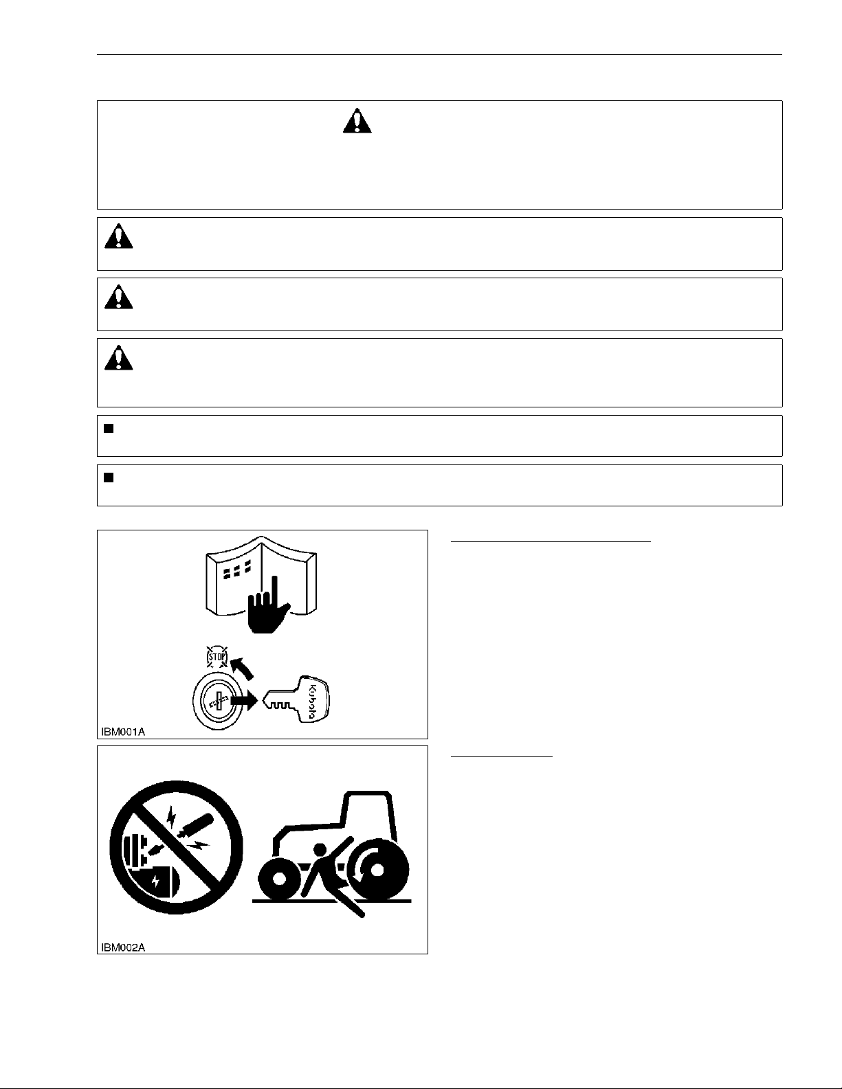
BEFORE YOU START SERVICE
• Read all instructions and safety instructions in this
manual and on your machine safety decals.
• Clean the work area and machine.
• Park the machine on a stable and level ground, and
set the parking brake.
• Lower the implement to the ground.
• Stop the engine, then remove the key.
• Disconnect the battery negative cable.
• Hang a "DO NOT OPERATE" tag in the operator
station.
WSM000001INI0010US0
START SAFELY
• Do not do the procedures below when you start the
engine.
– short across starter terminals
– bypass the safety start switch
• Do not alter or remove any part of machine safety
system.
• Before you start the engine, make sure that all shift
levers are in neutral positions or in disengaged
positions.
• Do not start the engine when you stay on the ground.
Start the engine only from operator's seat.
WSM000001INI0015US0
SAFETY FIRST
• This symbol, the industry's "Safety Alert Symbol", is used throughout this manual and on labels on the
machine itself to warn of the possibility of personal injury. Read these instructions carefully.
• It is essential that you read the instructions and safety regulations before you try to repair or use this
unit.
DANGER
• Indicates an imminently hazardous situation which, if not avoided, will result in death or serious injury.
WARNING
• Indicates a potentially hazardous situation which, if not avoided, could result in death or serious injury.
CAUTION
• Indicates a potentially hazardous situation which, if not avoided, may result in minor or moderate
injury.
IMPORTANT
• Indicates that equipment or property damage could result if instructions are not followed.
NOTE
• Gives helpful information.
KiSC issued 11, 2014 A
Page 6
INFORMATION
B2301, B2601, WSM
I-2
OPERATE SAFELY
• Do not use the machine after you consume alcohol
or medication or when you are tired.
• Put on applicable clothing and safety equipment.
• Use applicable tools only. Do not use alternative
tools or parts.
• When 2 or more persons do servicing, make sure
that you do it safely.
• Do not operate below the machine that only a jack
holds. Always use a safety stand to hold the
machine.
• Do not touch the hot parts or parts that turn when the
engine operates.
• Do not remove the radiator cap when the engine
operates, or immediately after it stops. If not, hot
water can spout out from the radiator. Only remove
the radiator cap when it is at a sufficiently low
temperature to touch with bare hands. Slowly loosen
the cap to release the pressure before you remove it
fully.
• Released fluid (fuel or hydraulic oil) under pressure
can cause damage to the skin and cause serious
injury. Release the pressure before you disconnect
hydraulic or fuel lines. Tighten all connections before
you apply the pressure.
• Do not open a fuel system under high pressure.
The fluid under high pressure that stays in fuel lines
can cause serious injury. Do not disconnect or repair
the fuel lines, sensors, or any other components
between the fuel pump and injectors on engines with
a common rail fuel system under high pressure.
• Put on an applicable ear protective device (earmuffs
or earplugs) to prevent injury against loud noises.
• Be careful about electric shock. The engine
generates a high voltage of more than DC100 V in
the ECU and is applied to the injector.
WSM000001INI0012US0
PREVENT A FIRE
• Fuel is very flammable and explosive under some
conditions. Do not smoke or let flames or sparks in
your work area.
• To prevent sparks from an accidental short circuit,
always disconnect the battery negative cable first
and connect it last.
• The battery gas can cause an explosion. Keep the
sparks and open flame away from the top of battery,
especially when you charge the battery.
• Make sure that you do not spill fuel on the engine.
WSM000001INI0005US0
KiSC issued 11, 2014 A
Page 7
INFORMATION
B2301, B2601, WSM
I-3
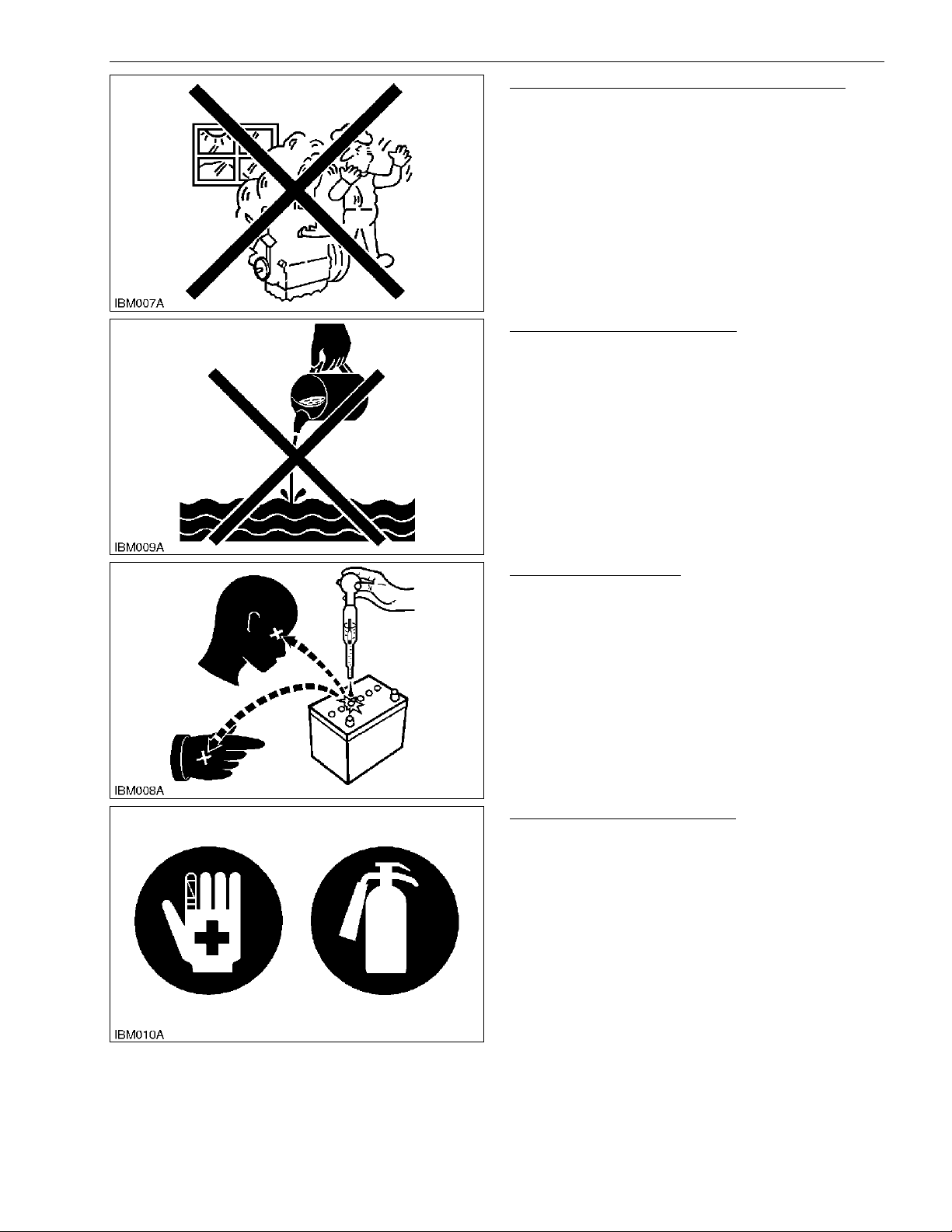
KEEP A GOOD AIRFLOW IN THE WORK AREA
• If the engine is in operation, make sure that the area
has good airflow. Do not operate the engine in a
closed area. The exhaust gas contains poisonous
carbon monoxide.
WSM000001INI0006US0
DISCARD FLUIDS CORRECTLY
• Do not discard fluids on the ground, down the drain,
into a stream, pond, or lake. Obey related
environmental protection regulations when you
discard oil, fuel, coolant, electrolyte and other
dangerous waste.
WSM000001INI0007US0
PREVENT ACID BURNS
• Keep electrolyte away from your eyes, hands and
clothing. Sulfuric acid in battery electrolyte is
poisonous and it can burn your skin and clothing and
cause blindness. If you spill electrolyte on yourself,
clean yourself with water, and get medical aid
immediately.
WSM000001INI0008US0
PREPARE FOR EMERGENCIES
• Keep a first aid kit and fire extinguisher ready at all
times.
• Keep the emergency contact telephone numbers
near your telephone at all times.
WSM000001INI0009US0
KiSC issued 11, 2014 A
Page 8
INFORMATION
B2301, B2601, WSM
I-4
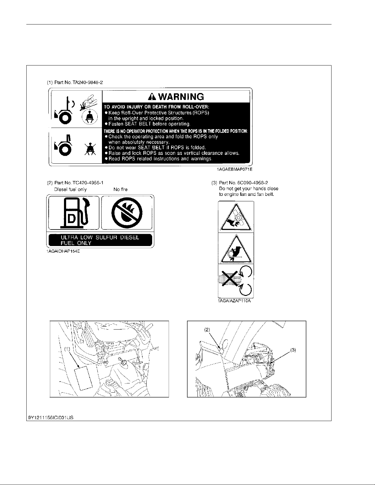
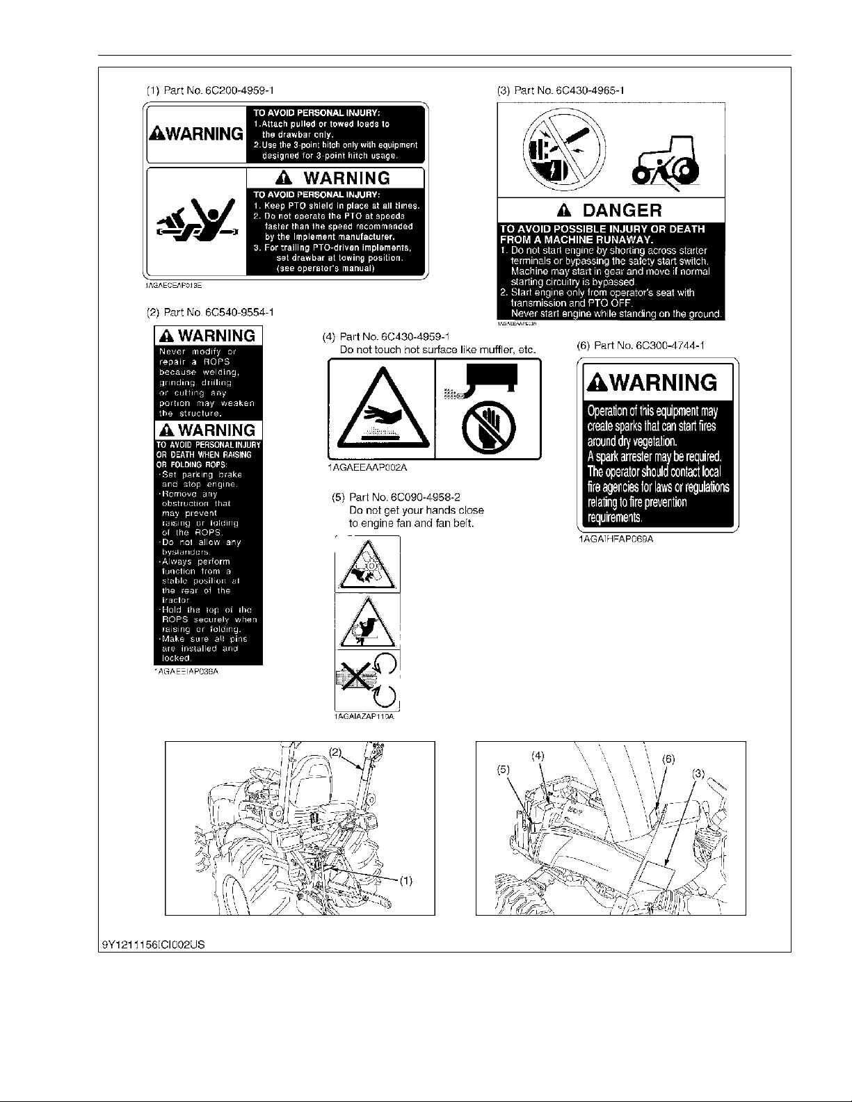
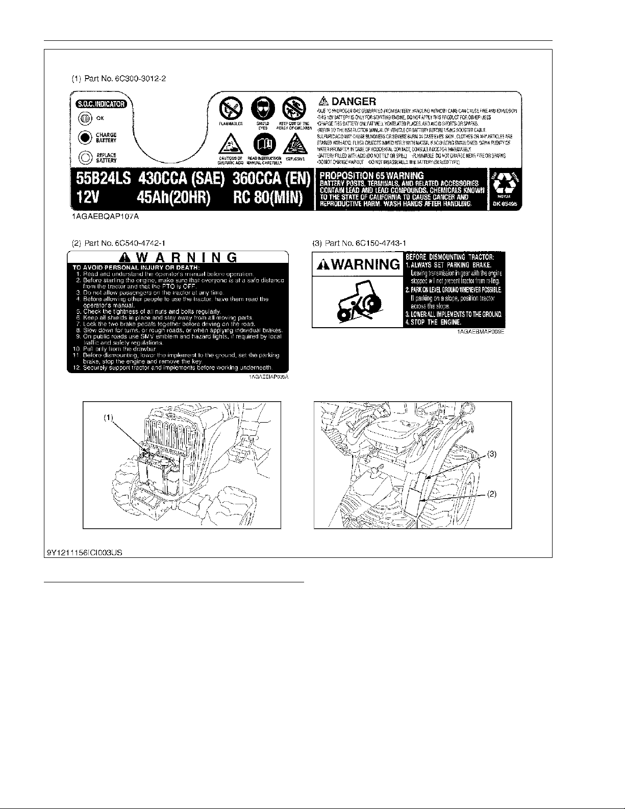
2. SAFETY DECALS
The following safety decals are installed on the machine. If a decal becomes damaged, illegible or is not
on the machine, replace it. The decal part number is listed in the parts list.
WSM000001INI0013US0
9Y1211156INI0004US0
KiSC issued 11, 2014 A
Page 9
INFORMATION
B2301, B2601, WSM
I-5
9Y1211156INI0005US0
KiSC issued 11, 2014 A
Page 10
INFORMATION
B2301, B2601, WSM
I-6
9Y1211156INI0006US0
CARE OF DANGER, WARNING AND CAUTION LABELS
1. Keep danger, warning and caution labels clean and free from obstructing material.
2. Clean danger, warning and caution labels with soap and water, dry with a soft cloth.
3. Replace damaged or missing danger, warning and caution labels with new labels.
4. If a component with danger, warning and caution label(s) affixed is replaced with new part, make sure new label(s)
is (are) attached in the same location(s) as the replace component.
5. Mount new danger, warning and caution labels by applying on a clean dry surface and pressing any bubbles to
outside edge.
9Y1211156INI0007US0
KiSC issued 11, 2014 A
Page 11

INFORMATION
B2301, B2601, WSM
I-7
3. SPECIFICATIONS
NOTE
• * Manufacturer's estimate
The company reserves the right to change the specifications without notice.
9Y1211156INI0001US0
Model B2301 B2601
PTO power *1 17.5 kW (13.0 HP) 19.5 kW (14.5 HP)
Engine
Maker KUBOTA
Model D1005-E4-D32 D1105-E4-D32
Type E-TVCS. Liquid-cooled, 3-cylinder diesel
Number of cylinders 3
Bore and stroke 76 × 73.6 mm (3.0 × 2.9 in.) 78 × 78.4 mm (3.1 × 3.1 in.)
Total displacement 1001 cc (61.1 cu.in.) 1123 cc (68.5 cu.in.)
Engine gross power *1 22 kW (16.4 HP) 25.5 kW (19.0 HP)
Rated revolution 2800 min
-1
(rpm)
Low idling revolution 1000 to 1100 min
-1
(rpm)
Maximum torque 60 N·m (6.1 kgf· m, 44 lbf·ft) 71 N·m (7.2 kgf·m, 52 lbf·ft)
Battery 12 V, RC: 80 min, CCD: 430 A
Capacities
Fuel tank 23 L (6.1 U.S.gals, 5.1 Imp.gals)
Engine crankcase (with filter) 3.1 L (3.3 U.S.qts, 2.7 Imp.qts)
Engine coolant 3.8 L (4.0 U.S.qts, 3.3 Imp.qts)
Transmission case 15 L (4.0 U.S.gals, 3.3 Imp.gals)
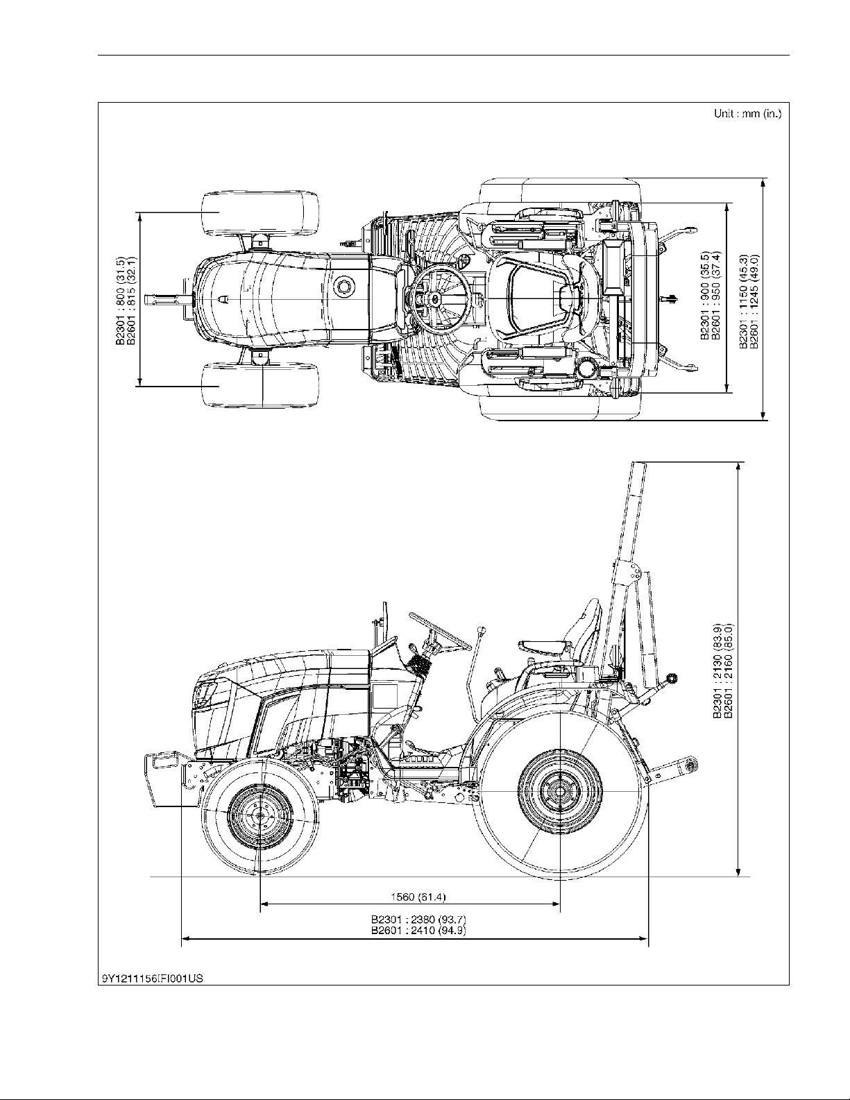
Dimensions
Overall length (without 3P) 2380 mm (93.7 in.) 2410 mm (94.9 in.)
Overall width (min. tread) 1150 mm (45.3 in.) 1245 mm (49.0 in.)
Overall height 2130 mm (83.9 in.) 2160 mm (85.0 in.)
Wheel base 1560 mm (61.4 in.)
Minimum ground clearance 305 mm (12.0 in.) 325 mm (12.8 in.)
Tread
Front 800 mm (31.5 in.) 815 mm (32.1 in.)
Rear 900 mm (35.5 in.) 950 mm (37.4 in.)
Weight 710 kg (1566 lbs) 740 kg (1632 lbs)
Clutch Not applicable
Traveling
system
Tires
Front 6-12 7-12
Rear 9.5-16 11.2-16
Steering Hydraulic type power steering
Transmission HST (3 range)
Brake Wet disk type
Minimum turning radius (with
brake)
2.1 m (6.9 feet)
Hydraulic unit
Hydraulic control system Position Control Valve
Pump capacity 31.4 L/min (8.3 gals/min)
3-point hitch SAE Category 1
Max. lift force
At lift points 820 kg (1808 lbs)
24 in. behind
lift point
640 kg (1411 lbs)
PTO
Rear-PTO SAE 1-3/8, 6 splines
PTO / Engine
speed
540 min
-1
(rpm) / 2768 min-1 (rpm)
Mid-PTO USA No.5 (KUBOTA 10-tooth) involute spline
PTO / Engine
speed
2500 min
-1
(rpm) / 2753 min-1 (rpm)
KiSC issued 11, 2014 A
Page 12

INFORMATION
B2301, B2601, WSM
I-8
4. TRAVELING SPEEDS
(At rated engine rpm)
The company reserves the right to change the specification without notice.
9Y1211156INI0002US0
Model B2301HSD
Tire size (Rear) 9.5-16 Farm / 33 × 12.5-15 Turf / 12-16.5 Industry
Range gear shift
lever
km/h (mile/h)
Forward
Low 0 to 5.6 (0 to 3.5)
Middle 0 to 8.8 (0 to 5.5)
High 0 to 19.1 (0 to 11.8)
Reverse
Low 0 to 4.2 (0 to 2.6)
Middle 0 to 6.6 (0 to 4.1)
High 0 to 14.3 (0 to 8.9)
Model B2601HSD
Tire size (Rear) 11.2-16 Farm 33 × 12.5-15 Turf / 12-16.5 Industry
Range gear shift
lever
km/h (mile/h)
Forward
Low 0 to 6.0 (0 to 3.7) 0 to 5.6 (0 to 3.5)
Middle 0 to 9.5 (0 to 5.9) 0 to 8.8 (0 to 5.5)
High 0 to 20.4 (0 to 12.7) 0 to 19.1 (0 to 11.8)
Reverse
Low 0 to 4.5 (0 to 2.8) 0 to 4.2 (0 to 2.6)
Middle 0 to 7.1 (0 to 4.4) 0 to 6.6 (0 to 4.1)
High 0 to 15.3 (0 to 9.5) 0 to 14.3 (0 to 8.9)
KiSC issued 11, 2014 A
Page 13
INFORMATION
B2301, B2601, WSM
I-9
5. DIMENSIONS
9Y1211156INI0003US0
KiSC issued 11, 2014 A
Page 14

G GENERAL
KiSC issued 11, 2014 A
Page 15

CONTENTS
1. TRACTOR IDENTIFICATION ....................................................................................................... G-1
2. GENERAL PRECAUTIONS.......................................................................................................... G-2
3. HANDLING PRECAUTIONS FOR ELECTRICAL PARTS AND WIRING .................................... G-3
[1] WIRING .................................................................................................................................. G-3
[2] BATTERY ............................................................................................................................... G-5
[3] FUSE ...................................................................................................................................... G-5
[4] CONNECTOR ........................................................................................................................ G-5
[5] HANDLING OF CIRCUIT TESTER ........................................................................................ G-6
[6] COLOR OF WIRING ..............................................................................................................G-7
4. LUBRICANTS, FUEL AND COOLANT......................................................................................... G-8
5. TIGHTENING TORQUES ........................................................................................................... G-11
[1] GENERAL USE SCREWS, BOLTS AND NUTS .................................................................. G-11
[2] STUD BOLTS ....................................................................................................................... G-11
[3] METRIC SCREWS, BOLTS AND NUTS .............................................................................. G-12
[4] AMERICAN STANDARD SCREWS, BOLTS AND NUTS WITH UNC OR UNF
THREADS ............................................................................................................................ G-12
[5] PLUGS ................................................................................................................................. G-12
6. MAINTENANCE CHECK LIST ................................................................................................... G-13
7. CHECK AND MAINTENANCE ................................................................................................... G-15
[1] DAILY CHECK...................................................................................................................... G-15
[2] CHECK POINTS OF EVERY 50 HOURS ............................................................................ G-19
[3] CHECK POINTS OF EVERY 100 HOURS .......................................................................... G-21
[4] CHECK POINTS OF EVERY 200 HOURS .......................................................................... G-25
[5] CHECK POINTS OF EVERY 400 HOURS .......................................................................... G-28
[6] CHECK POINT OF EVERY 800 HOURS ............................................................................. G-30
[7] CHECK POINT OF EVERY 1500 HOURS ........................................................................... G-30
[8] CHECK POINT OF EVERY 3000 HOURS ........................................................................... G-30
[9] CHECK POINT OF EVERY 1 YEAR .................................................................................... G-30
[10]CHECK POINTS OF EVERY 2 YEARS ............................................................................... G-31
[11]OTHERS............................................................................................................................... G-33
8. SPECIAL TOOLS ................................................................................................................
....... G-35
[1]
SPECIAL TO
OLS FOR ENGINE .......................................................................................... G-35
[2] SPECIAL TOOLS FOR TRACTOR ...................................................................................... G-42
9. TIRES ......................................................................................................................................... G-45
[1] TIRE PRESSURE................................................................................................................. G-45
[2] WHEEL ADJUSTMENT........................................................................................................ G-46
(1) Front Wheels .................................................................................................................. G-46
(2) Rear Wheels................................................................................................................... G-48
[3] BALLAST.............................................................................................................................. G-50
10. IMPLEMENT LIMITATIONS ....................................................................................................... G-52
GENERAL
KiSC issued 11, 2014 A
Page 16
GENERAL
B2301, B2601, WSM
G-1
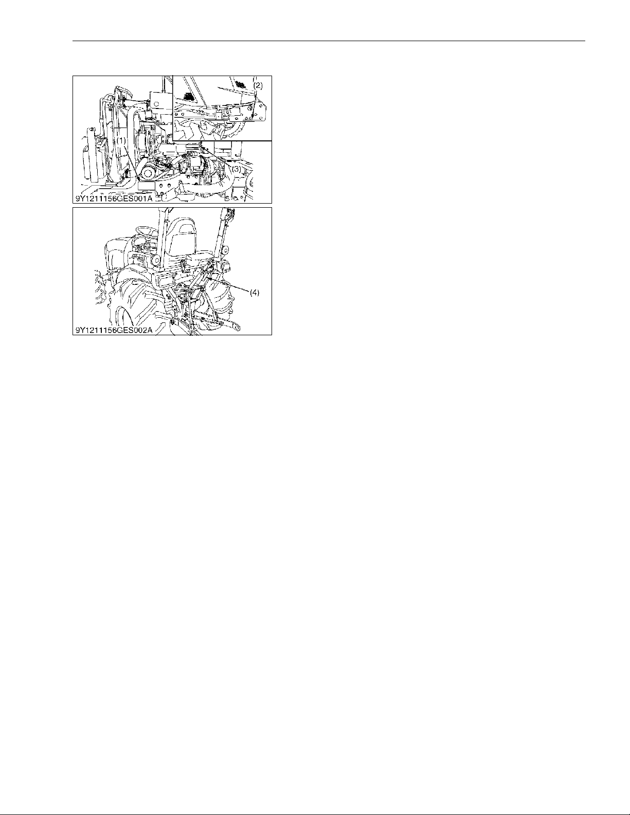
1. TRACTOR IDENTIFICATION
When contacting your local KUBOTA distributor, always specify
engine serial number, tractor serial number and hour meter reading.
9Y1211156GEG0001US0
(1) Tractor Identification Plate
(2) Tractor Serial Number
(3) Engine Serial Number
(4) ROPS Identification Plate
(ROPS Serial Number)
KiSC issued 11, 2014 A
Page 17
GENERAL
B2301, B2601, WSM
G-2
2. GENERAL PRECAUTIONS
• When you disassemble, carefully put the parts in a clean area
to make it easy to find the parts. You must install the screws,
bolts and nuts in their initial position to prevent the reassembly
errors.
• When it is necessary to use special tools, use KUBOTA special
tools. Refer to the drawings when you make special tools that
you do not use frequently.
• Before you disassemble or repair machine, make sure that you
always disconnect the ground cable from the battery first.
• Remove oil and dirt from parts before you measure.
• Use only KUBOTA genuine parts for replacement to keep the
machine performance and to make sure of safety.
• You must replace the gaskets and O-rings when you assemble
again. Apply grease (1) to new O-rings or oil seals before you
assemble.
• When you assemble the external or internal snap rings, make
sure that the sharp edge (3) faces against the direction from
which force (2) is applied.
• When inserting spring pins, their splits must face the direction
from which a force is applied. See the figure left side.
• To prevent damage to the hydraulic system, use only specified
fluid or equivalent.
• Clean the parts before you measure them.
• Tighten the fittings to the specified torque. Too much torque can
cause damage to the hydraulic units or the fittings. Not sufficient
torque can cause oil leakage.
• When you use a new hose or pipe, tighten the nuts to the
specified torque. Then loosen (approx. by 45 °) and let them be
stable before you tighten to the specified torque (This is not
applied to the parts with seal tape).
• When you remove the two ends of a pipe, remove the lower end
first.
• Use two pliers in removal and installation. One to hold the stable
side, and the other to turn the side you remove to prevent twists.
• Make sure that the sleeves of flared connectors and tapers of
hoses are free of dust and scratches.
• After you tighten the fittings, clean the joint and apply the
maximum operation pressure 2 to 3 times to check oil leakage.
WSM000001GEG0106US0
(1) Grease
(2) Force
(3) Sharp Edge
(4) Axial Force
(5) Rotating Movement
(A) External Circlip
(B) Internal Circlip
KiSC issued 11, 2014 A
Page 18
GENERAL
B2301, B2601, WSM
G-3
3. HANDLING PRECAUTIONS FOR ELECTRICAL PARTS AND WIRING
To ensure safety and prevent damage to the machine and
surrounding equipment, obey the following precautions in handling
electrical parts and wiring.
IMPORTANT
• Check electrical wiring for damage and loosened
connection every year. To this end, educate the customer
to do his or her own check and at the same time
recommend the dealer to perform periodic check for a fee.
• Do not try to modify or remodel any electrical parts and
wiring.
• When removing the battery cables, disconnect the negative
cable first. When installing the battery cables, connect the
positive cable first.
WSM000001GEG0062US0
[1] WIRING
• Securely tighten wiring terminals.
WSM000001GEG0063US0
• Do not let wiring contact dangerous part.
WSM000001GEG0064US0
• Repair or change torn or aged wiring immediately.
WSM000001GEG0065US0
(1) Negative Terminal (2) Positive Terminal
(1) Correct
(Securely Tighten)
(2) Incorrect
(Loosening Leads to Faulty Contact)
(1) Dangerous Part (Sharp Edge)
(2) Wiring (Incorrect)
(3) Wiring (Correct)
(4) Dangerous Part
(1) Aged
(2) Torn
(3) Insulating Vinyl Tape
KiSC issued 11, 2014 A
Page 19
GENERAL
B2301, B2601, WSM
G-4
• Securely insert grommet.
WSM000001GEG0066US0
• Securely clamp, being careful not to damage wiring.
WSM000001GEG0067US0
• Clamp wiring so that there is no twist, unnecessary sag, or
excessive tension, except for movable part, where sag be
required.
WSM000001GEG0068US0
• In installing a part, be careful not to get wiring caught by it.
WSM000001GEG0069US0
• After installing wiring, check protection of terminals and
clamped condition of wiring.
WSM000001GEG0070US0
(1) Grommet (A) Correct
(B) Incorrect
(1) Clamp
(Wind Clamp Spirally)
(2) Wire Harness
(3) Clamp
(4) Welding Dent
(1) Wiring
(2) Clamp
(A) Correct
(B) Incorrect
(1) Wiring (A) Incorrect
(1) Cover
(Securely Install Cover)
KiSC issued 11, 2014 A
Page 20
GENERAL
B2301, B2601, WSM
G-5
[2] BATTERY
• Be careful not to confuse positive and negative terminal posts.
• When you remove battery cables, disconnect negative cable
first. When you install battery cables, check for polarity and
connect positive cable first.
• Do not install any battery with capacity other than is specified
(Ah).
• After you connect cables to battery terminal posts, apply high
temperature grease to them and securely install terminal covers
on them.
• Do not allow dirt and dust to collect on battery.
DANGER
To avoid serious injury or death:
• Be careful not to let battery liquid spill on your skin and
clothes. If contaminated, wash it off with water
immediately.
• Before you recharge the battery, remove it from the
machine.
• Before you recharge, remove cell caps.
• Recharge in a well-ventilated place where there is no open
flame nearby, as hydrogen gas and oxygen are formed.
WSM000001GEG0071US0
[3] FUSE
• Use fuses with specified capacity.
Neither too large nor small capacity fuse is acceptable.
• Never use steel nor copper wire in place of fuse.
• Do not install working light, radio set, etc. on machine which is
not provided with reserve power supply.
• Do not install accessories if fuse capacity of reserve power
supply is exceeded.
WSM000001GEG0072US0
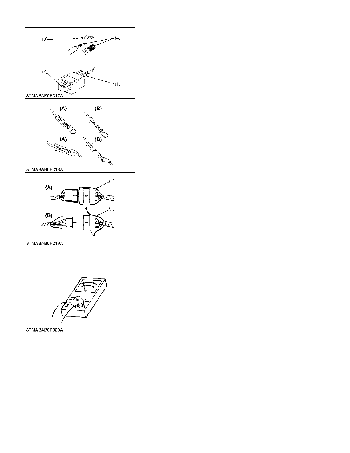
[4] CONNECTOR
• For connector with lock, push lock to separate.
WSM000001GEG0073US0
• In separating connectors, do not pull wire harnesses.
• Hold connector bodies to separate.
WSM000001GEG0074US0
(1) Fuse
(2) Fusible Link
(3) Slow Blow Fuse
(A) Push
(A) Correct (B) Incorrect
KiSC issued 11, 2014 A
Page 21
GENERAL
B2301, B2601, WSM
G-6
• Use sandpaper to remove rust from terminals.
• Repair deformed terminal. Make sure that there is no terminal
being exposed or displaced.
WSM000001GEG0075US0
• Make sure that there is no female connector being too open.
WSM000001GEG0076US0
• Make sure that plastic cover is large enough to cover whole
connector.
WSM000001GEG0077US0
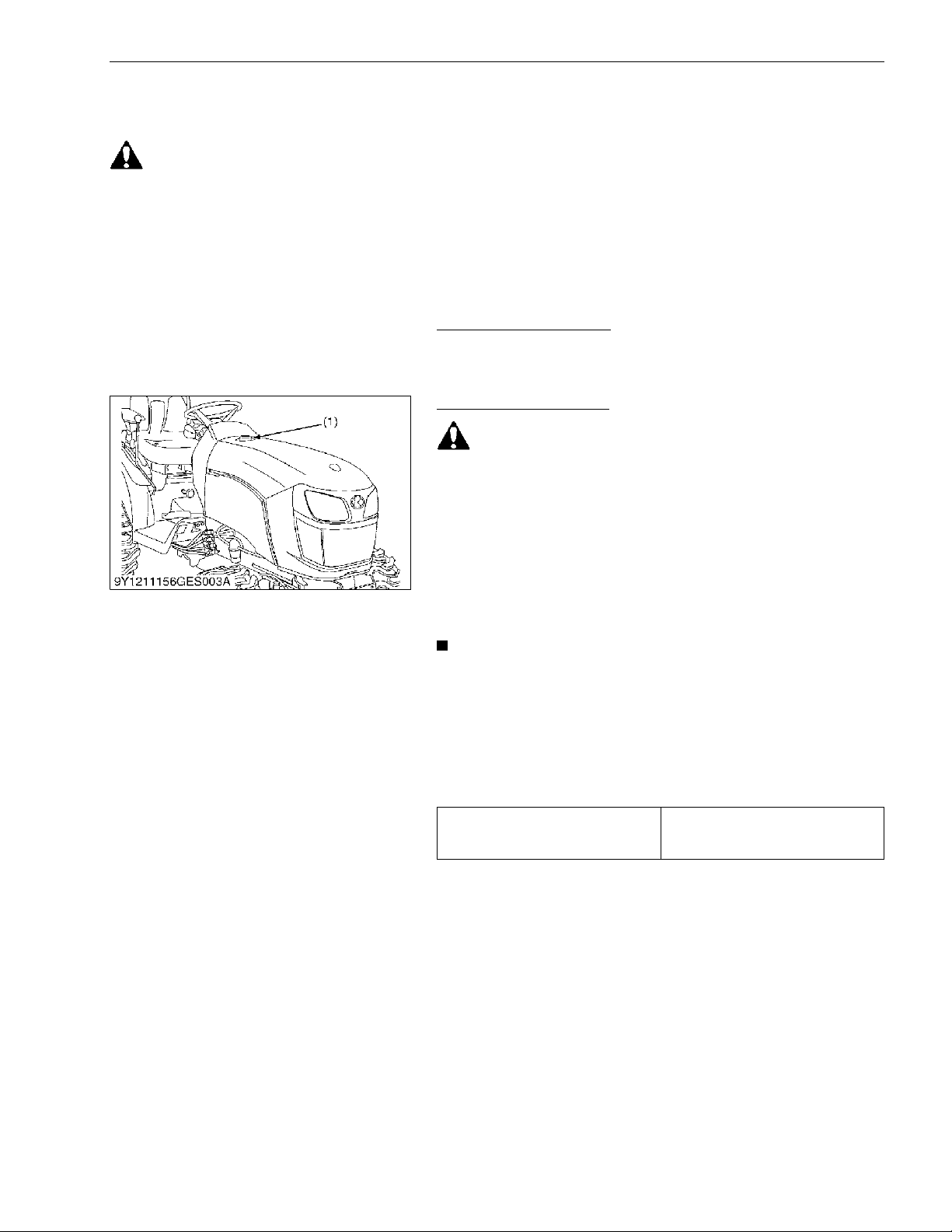
[5] HANDLING OF CIRCUIT TESTER
• Use tester correctly following manual provided with tester.
• Check for polarity and range.
WSM000001GEG0078US0
(1) Exposed Terminal
(2) Deformed Terminal
(3) Sandpaper
(4) Rust
(A) Correct (B) Incorrect
(1) Cover (A) Correct
(B) Incorrect
KiSC issued 11, 2014 A
Page 22
GENERAL
B2301, B2601, WSM
G-7
[6] COLOR OF WIRING
• Colors of wire are specified to the color codes.
• This symbol of "/" shows color with stripe(s).
(An example)
Red stripe on white color: W/R
WSM000001GEG0079US0
Color of wiring Color code
Black B
Brown Br
Green G
Gray Gy or Gr
Blue L
Light Green Lg
Orange Or
Pink P
Purple Pu or V
Red R
Sky Blue Sb
White W
Yell ow Y
(1) Wire Color (2) Stripe
KiSC issued 11, 2014 A
Page 23

GENERAL
B2301, B2601, WSM
G-8
4. LUBRICANTS, FUEL AND COOLANT
NOTE
• *KUBOTA UDT or SUPER UDT fluid --- KUBOTA original transmission hydraulic fluid
9Y1211156GEG0002US0
No. Place
Capacity
Lubricants, fuel and coolant
B2301 B2601
1 Fuel tank
23 L
6.1 U.S.gals
5.1 Imp.gals
• No. 2-D diesel fuel
• No. 1-D diesel fuel if temperature
is below –10 °C (14 °F)
2
Coolant (with recovery
tank)
3.8 L
4.0 U.S.qts
3.3 Imp.qts
Fresh clean soft water with
anti-freeze
3
Engine crankcase
(with filter)
3.1 L
3.3 U.S.qts
2.7 Imp.qts
Engine oil: Refer to next page
• Above 25 °C (77 °F)
SAE30, SAE10W-30 or 15W-40
• −10 to 25 °C
(14 to 77 °F)
SAE20, SAE10W-30 or 15W-40
• Below −10 °C (14 °F)
SAE10W-30
4 Transmission case
15 L
4.0 U.S.gals
3.3 Imp.gals
KUBOTA SUPER UDT-2 fluid*
5 Front axle case
3.5 L
3.7 U.S.qts
3.1 Imp.qts
KUBOTA SUPER UDT-2 fluid* or
SAE80 - SAE90 gear oil
Greasing No. of greasing point Capacity Type of grease
6
Top link 1
Until grease
overflows
Multipurpose
type grease
NLGI-2 or
NLGI-1
(GC-LB)
Lift rod [RH] 1
Brake pedal 1
Battery terminal 2
Moderate
amount
KiSC issued 11, 2014 A
Page 24

GENERAL
B2301, B2601, WSM
G-9
NOTE
<For North American market>
Engine Oil
• Oil used in the engine should have an American Petroleum Institute (API) service classification and
Proper SAE Engine Oil according to the ambient temperatures as shown above :
• Refer to the following table for the suitable API classification engine oil according to the engine type (with
internal EGR, external EGR or non-EGR) and the fuel (low-sulfur or high-sulfur fuel).
EGR: Exhaust Gas Re-circulation
• The CJ-4 engine oil is intended for DPF (Diesel Particulate Filter) type engines, and cannot be used on
this tractor.
Fuel
• Cetane number of 45 minimum. Cetane number greater then 50 is preferred, especially for temperatures
below −20 °C (−4 °F) or elevations above 1500 m (5000 ft).
• Diesel fuels specified to EN 590 or ASTM D975 are recommended.
• No.2-D is a distillate fuel of lower volatility for engine in industrial and heavy mobile service. (SAE J313
JUN87)
Transmission oil
• KUBOTA Super UDT-2: For an enhanced ownership experience, we highly recommend Super UDT-2 to be
used instead of standard hydraulic/transmission fluid.
Super UDT-2 is a proprietary KUBOTA formulation that delivers superior performance and protection in
all operating conditions.
Regular UDT is also permitted for use in this machine.
Indicated capacities of water and oil are manufacturer's estimate.
Fuel used
Engine oil classification (API classification)
Oil class of engines except external EGR Oil class of engines with external EGR
Ultra Low Sulfur Fuel
[< 0.0015 % (15 ppm)]
CF, CF-4, CG-4, CH-4 or CI-4
CF or CI-4
(Class CF-4, CG-4 and CH-4 engine oils
cannot be used on EGR type engines)
except external EGR With external EGR
Models B2301 / B2601 –
KiSC issued 11, 2014 A
Page 25

GENERAL
B2301, B2601, WSM
G-10
<For other than North American market>
Engine Oil
• Oil used in the engine should have an American Petroleum Institute (API) service classification and
Proper SAE Engine Oil according to the ambient temperatures as shown above :
• With the emission control now in effect, the CF-4 and CG-4 lubricating oils have been developed for use
of a low-sulfur fuel on on-road vehicle engines. When an off-road vehicle engine runs on a high-sulfur
fuel, it is advisable to employ the "CF or better" lubricating oil with a high Total Base Number (TBN of 10
minimum).
• Refer to the following table for the suitable API classification engine oil according to the engine type (with
internal EGR, external EGR or non-EGR) and the fuel (low-sulfur or high-sulfur fuel).
EGR: Exhaust Gas Re-circulation
• The CJ-4 engine oil is intended for DPF (Diesel Particulate Filter) type engines, and cannot be used on
this tractor.
Fuel
• Cetane number of 45 minimum. Cetane number greater then 50 is preferred, especially for temperatures
below −20 °C (−4 °F) or elevations above 1500 m (5000 ft).
• If diesel fuel with sulfur content greater than 0.5 % (5000 ppm) sulfur content in used, reduce the service
interval for engine oil and filter by 50 %.
• NEVER use diesel fuel with sulfur content greater than 0.05 % (500 ppm) for EXTERNAL EGR type engine.
• DO NOT use diesel fuel with sulfur content greater than 1.0 % (10000 ppm).
• Diesel fuels specified to EN 590 or ASTM D975 are recommended.
• No.2-D is a distillate fuel of lower volatility for engine in industrial and heavy mobile service. (SAE J313
JUN87)
Transmission oil
• The oil used to lubricate the transmission is also used as hydraulic fluid. To insure proper operation of
the hydraulic system and to complete lubrication of the transmission, it is important that a multi-grade
transmission fluid is used in this system. We recommend the use of KUBOTA UDT or SUPER UDT fluid
for optimum protection and performance.
Do not mix different brands together.
Indicated capacities of water and oil are manufacturer's estimate.
9Y1211156GEG0003US0
Fuel used
Engine oil classification (API classification)
Oil class of engines except external EGR Oil class of engines with external EGR
High Sulfur Fuel
[≥ 0.05 % (500 ppm)]
CF
(If the "CF-4, CG-4, CH-4, or CI-4"
lubricating oil is used with a high-sulfur
fuel, change the lubricating oil at shorter
intervals. (approximately half))
–
Low Sulfur Fuel
[(< 0.05 % (500 ppm)]
or Ultra Low Sulfur
Fuel [< 0.0015 %
(15 ppm)]
CF, CF-4, CG-4, CH-4 or CI-4
CF or CI-4
(Class CF-4, CG-4 and CH-4 engine oils
cannot be used on EGR type engines)
except external EGR With external EGR
Models B2301 / B2601 –
KiSC issued 11, 2014 A
Page 26

GENERAL
B2301, B2601, WSM
G-11
5. TIGHTENING TORQUES
Tighten screws, bolts and nuts whose tightening torques are not specified in this Workshop Manual
according to the table below.
WSM000001GEG0116US0
[1] GENERAL USE SCREWS, BOLTS AND NUTS
WSM000001GEG0117US0
[2] STUD BOLTS
WSM000001GEG0002US0
Indication on top of bolt
No-grade or 4T 7T 9T
Indication on top of nut
No-grade or 4T
6T
Material of opponent part Ordinariness Aluminum Ordinariness Aluminum Ordinariness
Unit N·m kgf·m lbf·ft N·m kgf·m lbf·ft N·m kgf·m lbf·ft N·m kgf·m lbf·ft N·m kgf·m lbf·ft
M6
7.9
to
9.3
0.80
to
0.95
5.8
to
6.8
7.9
to
8.8
0.80
to
0.90
5.8
to
6.5
9.81
to
11. 2
1.00
to
1.15
7.24
to
8.31
7.9
to
8.8
0.80
to
0.90
5.8
to
6.5
12.3
to
14.2
1.25
to
1.45
9.05
to
10.4
M8
18
to
20
1.8
to
2.1
13
to
15
17
to
19
1.7
to
2.0
13
to
14
24
to
27
2.4
to
2.8
18
to
20
18
to
20
1.8
to
2.1
13
to
15
30
to
34
3.0
to
3.5
22
to
25
M10
40
to
45
4.0
to
4.6
29
to
33
32
to
34
3.2
to
3.5
24
to
25
48
to
55
4.9
to
5.7
36
to
41
40
to
44
4.0
to
4.5
29
to
32
61
to
70
6.2
to
7.2
45
to
52
M12
63
to
72
6.4
to
7.4
47
to 53–––
78
to
90
7.9
to
9.2
58
to
66
63
to
72
6.4
to
7.4
47
to
53
103
to
117
10.5
to
12.0
76.0
to
86.7
M14
108
to
125
11. 0
to
12.8
79.6
to
92.5
–––
124
to
147
12.6
to
15.0
91.2
to
108
–––
1
67
to
196
17.0
to
20.0
123
to
144
M16
167
to
191
17.0
to
19.5
123
to
14
1
–––
197
to
225
20.0
to
23.0
145
to
166
–––
260
to
304
26.5
to
31.0
192
to
224
M18
246
to
284
25.0
to
29.0
181
to
209
–––
275
to
318
28.0
to
32.5
203
to
235
–––
344
to
402
35.0
to
41.0
254
to
296
M20
334
to
392
34.0
to
40.0
246
to
289
–––
368
to
431
37.5
to
44.0
272
to
318
–––
491
to
568
50.0
to
58.0
362
to
419
Material of opponent part Ordinariness Aluminum
Unit N·m kgf·m lbf·ft N·m kgf·m lbf·ft
M8
12
to
15
1.2
to
1.6
8.7
to
11
8.9
to
11
0.90
to
1.2
6.5
to
8.6
M10
25
to
31
2.5
to
3.2
18
to
23
20
to
25
2.0
to
2.6
15
to
18
M12
30
to
49
3.0
to
5.0
22
to 3631 3.2 23
M14
62
to
73
6.3
to
7.5
46
to 54–––
M16
98.1
to
112
10.0
to
11. 5
72.4
to
83.1
–––
M18
172
to
201
17.5
to
20.5
127
to
148
–––
KiSC issued 11, 2014 A
Page 27
GENERAL
B2301, B2601, WSM
G-12
[3] METRIC SCREWS, BOLTS AND NUTS
WSM000001GEG0003US0
[4] AMERICAN STANDARD SCREWS, BOLTS AND NUTS WITH
UNC OR UNF THREADS
WSM000001GEG0008US0
[5] PLUGS
WSM000001GEG0005US0
Grade
Property class 8.8 Property class 10.9
Unit N·m kgf·m lbf·ft N·m kgf·m lbf·ft
M8 24 to 27 2.4 to 2.8 18 to 20 30 to 34 3.0 to 3.5 22 to 25
M10 48 to 55 4.9 to 5.7 36 to 41 61 to 70 6.2 to 7.2 45 to 52
M12 78 to 90 7.9 to 9.2 58 to 66 103 to 117 10.5 to 12.0 76.0 to 86.7
M14 124 to 147 12.6 to 15.0 91.2 to 108 167 to 196 17.0 to 20.0 123 to 144
M16 197 to 225 20.0 to 23.0 145 to 166 260 to 304 26.5 to 31.0 192 to 224
Grade
SAE GR.5 SAE GR.8
Unit N·m kgf·m lbf·ft N·m kgf·m lbf·ft
1/4 11.7 to 15.7 1.20 to 1.60 8.63 to 11.5 16.3 to 19.7 1.67 to 2.00 12.0 to 14.6
5/16 23.1 to 27.7 2.36 to 2.82 17.0 to 20.5 33 to 39 3.4 to 3.9 25 to 28
3/8 48 to 56 4.9 to 5.7 36 to 41 61 to 73 6.3 to 7.4 45 to 53
1/2 110 to 130 11.3 to 13.2 81.2 to 95.8 150 to 178 15.3 to 18.1 111 to 131
9/16 150 to 178 15.3 to 18.1 111 to 131 217 to 260 22.2 to 26.5 160 to 191
5/8 204 to 244 20.8 to 24.8 151 to 179 299 to 357 30.5 to 36.4 221 to 263
Shape Size
Material of opponent part
Ordinariness Aluminum
N·m kgf·m lbf·ft N·m kgf·m lbf·ft
Tapered screw
R1/8 13 to 21 1.3 to 2.2 9.4 to 15 13 to 19 1.3 to 2.0 9.4 to 14
R1/4 25 to 44 2.5 to 4.5 18 to 32 25 to 34 2.5 to 3.5 18 to 25
R3/8 49 to 88 5.0 to 9.0 37 to 65 49 to 58 5.0 to 6.0 37 to 43
R1/2 58.9 to 107 6.00 to 11.0 43.4 to 79.5 59 to 78 6.0 to 8.0 44 to 57
Straight screw G1/4 25 to 34 2.5 to 3.5 18 to 25 – – –
G3/8 62 to 82 6.3 to 8.4 46 to 60 – – –
G1/2 49 to 88 5.0 to 9.0 37 to 65 – – –
KiSC issued 11, 2014 A
Page 28

GENERAL
B2301, B2601, WSM
G-13
6. MAINTENANCE CHECK LIST
No. Item
Indication on hour meter
Interval
Refer-
ence
page
50 100 150 200 250 300 350 400 450 500 550 600 650 700 800
1 Engine oil Change
every
200 Hr
G-26
2 Engine oil filter Replace
every
200 Hr
G-25
3 Transmission oil filters [HST] Replace
every
200 Hr
G-26
4 Hydraulic oil filter Replace
every
400 Hr
G-29
5 Transmission fluid Change
every
400 Hr
G-28
6 Front axle case oil Change
every
400 Hr
G-29
7 Front axle pivot Adjust
every
400 Hr
G-30
8 Engine start system Check
every
50 Hr
G-19
9 Greasing –
every
50 Hr
G-20
10 Wheel bolt torque Check
every
50 Hr
G-20
11 Battery condition Check
every
100 Hr
G-21 *4
12
Air cleaner element [Double
element type]
Primary element
Clean
every
100 Hr
G-23 *1
@
Replace
every 1
year
G-30 *2
Air cleaner element [Double
element type]
Secondary element
Replace
every 1
year
G-30
13 Fuel filter element
Clean
every
100 Hr
G-24
@
Replace
every
400 Hr
G-30
14 Fan belt Adjust
every
100 Hr
G-24
15 Brake Adjust
every
100 Hr
G-25
16 Radiator
hose and clamp
Check
every
200 Hr
G-27
Replace
every 2
years
G-33
17 Fuel line
Check
every
100 Hr
G-25
@
Replace
every 2
years
G-33 *3
18 Intake air line
Check
every
200 Hr
G-27
@
Replace
every 2
years
G-33 *3
19 Toe-in Adjust
every
200 Hr
G-28
20 Engine valve clearance Adjust
every
800 Hr
G-30
21
Fuel injection nozzle injection
pressure
Check
every
1500 Hr
G-30 @
22 Injection pump Check
every
3000 Hr
G-30 @
23 Cooling system Flush
every 2
years
G-31
KiSC issued 11, 2014 A
Page 29

GENERAL
B2301, B2601, WSM
G-14
IMPORTANT
• The jobs indicated by must be done after the first 50 hours of operation.
*1 Air cleaner should be cleaned more often in severe dusty conditions.
*2 Every year or after 6 cleanings.
*3 Replace only if necessary.
*4 When the battery is used for less than 100 hours per year, check the fluid level annually.
• The items listed above (@ marked) are registered as emission related critical parts by KUBOTA in the U.S.EPA nonroad emission
regulation. As the engine owner, you are responsible for the performance of the required maintenance on the engine according to
the above instruction.
Please see the Warranty Statement in detail.
9Y1211156GEG0004US0
24 Coolant Change
every 2
years
G-31
25 Fuel system Bleed
Service
as re-
quired
G-33
26 Clutch housing water Drain G-33
27 Fuse Replace G-34
28 Light bulb Replace G-34
No. Item
Indication on hour meter
Interval
Refer-
ence
page
50 100 150 200 250 300 350 400 450 500 550 600 650 700 800
KiSC issued 11, 2014 A
Page 30
GENERAL
B2301, B2601, WSM
G-15
7. CHECK AND MAINTENANCE
[1] DAILY CHECK
WARNING
To avoid personal injury or death:
Take the following precautions when checking the tractor.
• Park the machine on firm and level ground.
• Set the parking brake.
• Lower the implement to the ground.
• All residual pressure of the hydraulic system released.
• Stop the engine and remove the key.
9Y1211156GEG0005US0
Walk Around Inspection
1. Look around and under the tractor for such items as loose bolts,
trash build-up, oil or coolant leaks, broken or worn parts.
9Y1211156GEG0006US0
Checking and Refueling
WARNING
To avoid personal injury or death:
• Do not smoke while refueling.
• Be sure to stop the engine before refueling.
1. Turn the key switch to "ON", check the amount of fuel by fuel
gauge.
2. Fill fuel tank when fuel gauge shows 1/4 or less fuel in tank.
3. Use grade No.2-Diesel fuel at temperatures above −10 °C
(14 °F).
Use grade No.1-Diesel fuel at temperatures below −10 °C
(14 °F).
IMPORTANT
• Do not permit dirt or trash to get into the fuel system.
• Be careful not to let the fuel tank become empty, otherwise
air will enter the fuel system, necessitating bleeding before
next engine start.
• Be careful not to spill during refueling. If you should spill,
wipe it off at once, or it may cause a fire.
• To prevent condensation (water) accumulation in the fuel
tank, fill the tank before parking overnight.
9Y1211156GEG0007US0
Fuel tank capacity
23 L
6.1 U.S.gals
5.1 Imp.gals
(1) Fuel Tank Cap
KiSC issued 11, 2014 A
Page 31

GENERAL
B2301, B2601, WSM
G-16
Checking Engine Oil Level
WARNING
To avoid personal injury:
• Be sure to stop the engine before checking the oil level.
1. Park the machine on a flat surface.
2. Check engine oil before starting the engine or 5 minutes or more
after the engine has stopped.
3. To check the oil level, draw out the dipstick, wipe it clean,
replace it, and draw it out again. Check to see that the oil level
lies between the two notches.
If the level is too low, add new oil to the prescribed level at the
oil inlet.
IMPORTANT
• When using an oil of different maker or viscosity from the
previous one, remove all of the old oil.
Never mix two different types of oil.
• If oil level is low, do not run engine.
9Y1211156GEG0008US0
Checking Transmission Fluid Level
1. Park the machine on a flat surface, lower the implement and
shut off engine.
2. To check the oil level, draw out the dipstick, wipe it clean,
replace it, and draw it out again. check to see that the oil level
lies within the cross hatched area.
If the level it too low, add new oil to the prescribed level at the
oil inlet.
IMPORTANT
• If oil level is low, do not run engine.
9Y1211156GEG0009US0
Checking Coolant Level
WARNING
To avoid personal injury or death:
• Do not remove radiator cap while coolant is hot. When cool,
slowly rotate cap to the first stop and allow sufficient time
for excess pressure to escape before removing the cap
completely.
1. Check to see that the coolant level is between the "FULL" and
"LOW" makes of recovery tank.
2. When the coolant level drops due to evaporation, add soft water
only up to the full level.
In case of leakage, add anti-freeze and soft water in the
specified mixing ratio up to the full level.
IMPORTANT
• If the radiator cap has to be removed, follow the caution
above and securely retighten the cap.
• Use clean, fresh soft water and anti-freeze to fill the
recovery tank.
9Y1211156GEG0010US0
(1) Oil Inlet
(2) Dipstick
A: Oil level is acceptable within this
range.
(1) Oil Inlet
(2) Dipstick
A: Oil level is acceptable within this
range.
(1) Recovery Tank A: "FULL"
B: "LOW"
KiSC issued 11, 2014 A
Page 32

GENERAL
B2301, B2601, WSM
G-17
Cleaning Evacuator Valve
1. Open the evacuator valve to get rid of large particles of dust and
dirt.
9Y1211156GEG0011US0
Cleaning Grill and Radiator Screen
WARNING
To avoid personal injury or death:
• Be sure to stop the engine and remove the key before
removing the screen.
1. Check front grill and side screens to be sure they are clean of
debris.
2. Detach the screen and remove all foreign material and clean the
front of radiator completely.
IMPORTANT
• Grill and screen must be clean from debris to prevent
engine from overheating and to allow good air intake for
the air cleaner.
9Y1211156GEG0012US0
Checking Brake Pedal
1. Inspect the brake pedals for free travel, and smooth operation.
2. Adjust if incorrect measurement is found.
9Y1211156GEG0013US0
Checking Gauges, Meter and Easy Checker™
1. Inspect the instrument panel for broken gauge(s), meter(s) and
Easy Checker™.
2. Replace if broken.
9Y1211156GEG0014US0
Checking Head Light, Hazard Light etc.
1. Inspect the light for broken bulbs and lenses.
2. Replace if broken.
9Y1211156GEG0015US0
Checking Seat Belt and ROPS
1. Always check condition of seat belt and ROPS attaching
hardware before operating tractor.
2. Replace if damaged.
9Y1211156GEG0016US0
(1) Evacuator Valve
(1) Radiator Screen (A) "DETACH"
KiSC issued 11, 2014 A
Page 33

GENERAL
B2301, B2601, WSM
G-18
Checking and Cleaning of Electrical Wiring and Battery Cables
WARNING
To avoid personal injury or death:
• A loosened terminal or connector, or damaged wire may
affect the performance of electrical components or cause
short circuits. Leakage of electricity could result in a fire
hazard, a dead battery or damage to electrical components.
• Replace damaged wires or connections promptly.
• If a fuse blows soon after replacement, DO NOT USE A
LARGER THAN RECOMMENDED FUSE OR BYPASS THE
FUSE SYSTEM.
• Many wiring connections are protected by waterproof
plugs, plug and unplug these connections carefully and
make sure they are sealed correctly after assembly.
• Accumulation of dust, chaff or spilled fuel deposits around
the battery, electrical wiring, engine or exhaust system are
a fire hazard.
CLEAN THESE AREAS BEFORE STARTING WORK.
To avoid premature electrical malfunctions DO NOT APPLY
high pressure water directly to battery, wiring, connectors,
electrical components or instrument panel.
Inspect the following regularly:
1. Check wiring for chafed or cracked insulation.
2. Check wiring harness clamps. Replace if necessary.
3. Check connectors and terminals for looseness, contamination
or overheated (discolored) connectors.
4. Check instrument panel for correct operation of switches and
gauges.
9Y1211156GEG0017US0
Checking Movable Parts
1. If any of the movable parts, such as levers and pedals, is not
smoothly moved because of rust or anything sticky, do not
attempt to force it into motion.
In the above case, remove the rust or sticky thing, and apply oil
lor grease on the relevant spot.
Otherwise, the machine may get damaged.
9Y1211156GEG0018US0
KiSC issued 11, 2014 A
Page 34

GENERAL
B2301, B2601, WSM
G-19
[2] CHECK POINTS OF EVERY 50 HOURS
Checking Engine Start System
WARNING
To avoid personal injury or death:
• Do not allow anyone near the tractor while testing.
• If the tractor does not pass the test do not operate the
tractor.
• Detach an implement before testing.
Preparation before testing.
1. Sit on operator's seat.
2. Set the parking brake and stop the engine.
3. Shift the range gear shift lever to "NEUTRAL" position.
4. Place the speed control pedal in "NEUTRAL" position.
5. Shift the PTO clutch lever to "OFF" position.
Test: Switch for the speed control pedal.
1. Depress the speed control pedal.
2. Turn the key to "START" position.
3. The engine must not crank.
Test: Switch for the PTO clutch lever.
1. Place the speed control pedal in "NEUTRAL" position.
2. Shift the PTO clutch lever to "ON" position.
3. Turn the key to "START" position.
4. The engine must not crank.
Test: Switches for the operator's seat and the PTO clutch
lever.
1. Sit on the operator's seat.
2. Start the engine.
3. Shift the PTO clutch lever to "ON" position.
4. Release the parking brake.
5. Stand up. (Do not get off the machine.)
6. The engine must shut off after approximately 1 second.
9Y1211156GEG0019US0
(1) Range Gear Shift Lever
(2) PTO Clutch Lever
(3) Speed Control Pedal
(4) Operator's Seat
KiSC issued 11, 2014 A
Page 35

GENERAL
B2301, B2601, WSM
G-20
Lubricating Grease Fittings
1. Apply a small amount of multipurpose grease to the following
points every 50 hours:
If you operated the machine in extremely wet and muddy
conditions, lubricate grease fittings more often.
9Y1211156GEG0020US0
Checking Wheel Mounting Nuts Tightening Torque
WARNING
To avoid personal injury or death:
• Never operate tractor with a loose rim, wheel or axle.
• Any time bolts and nuts are loosened, retighten to
specified torque.
• Check all bolts and nuts frequently and keep them tight.
1. Check wheel bolts and nuts regularly especially when new. If
they are loose, tighten them as follows.
9Y1211156GEG0021US0
(1) Grease Fitting (Brake Pedals)
(2) Grease Fitting (Top Link)
(3) Grease Fitting (Lifting Rod, Right)
(4) Battery Terminals
Tightening torque
Front wheel mounting nut
78 to 90 N·m
8.0 to 9.1 kgf·m
58 to 66 lbf·ft
Rear wheel mounting nut
145 to 150 N·m
14.8 to 15.2 kgf·m
107 to 110 lbf·ft
(1) Front Wheel Mounting Nut (2) Rear Wheel Mounting Nut and Bolt
KiSC issued 11, 2014 A
Page 36

GENERAL
B2301, B2601, WSM
G-21
[3] CHECK POINTS OF EVERY 100 HOURS
Checking Battery Condition
DANGER
To avoid the possibility or battery explosion:
For the refillable type battery, follow the instructions below.
• Do not use or charge the refillable type battery if the fluid
level is below the LOWER (lower limit level) mark.
Otherwise, the battery component parts may prematurely
deteriorate, which may shorten the battery's service life or
cause an explosion. check the fluid level regularly and add
distilled water as required so that the fluid level is between
the UPPER and LOWER levels.
WARNING
To avoid personal injury or death:
• Never remove the battery cap while the engine is running.
• Keep electrolyte away from eyes, hands and clothes. If you
are spattered with it, wash it away completely with water
immediately and get medical attention.
• Keep open sparks and flames away from the battery at all
times. Hydrogen gas mixed with oxygen becomes very
explosive.
• Wear eye protection and rubber gloves when working
around battery.
1. Mishandling the battery shortens the service life and adds to
maintenance costs.
2. The original battery is maintenance free, but needs some
servicing.
3. If the battery is weak, the engine will be difficult to start and the
lights will be dim. It is important to check the battery periodically.
How to read the indicator
Check the battery condition by reading the indicator.
9Y1211156GEG0022US0
The factory-installed battery is of non-refillable type. If the
indicator turns white, do not charge the battery but replace
it with new one.
State of indicator display
Green
Specific gravity of electrolyte and quality of electrolyte
are both in good condition.
Black Needs charging battery.
White Needs replacing battery.
(1) Battery (2) Indicator
KiSC issued 11, 2014 A
Page 37

GENERAL
B2301, B2601, WSM
G-22
Battery Charging
WARNING
To avoid personal injury or death:
• When the battery is being activated, hydrogen and oxygen
gases in the battery are extremely explosive. Keep open
sparks and flames away from the battery at all times,
especially when charging the battery.
• When charging the battery, ensure the vent caps are
securely in place. (if equipped)
• When disconnecting the cable from the battery, start with
the negative terminal first.
When connecting the cable to the battery, start with the
positive terminal first.
• Never check battery charge by placing a metal object
across the posts.
Use a voltmeter or hydrometer.
1. To slow charge the battery, connect the battery positive terminal
to the charger positive terminal and the negative to the negative,
then recharge in the standard fashion.
2. A boost charge is only for emergencies. It will partially charge
the battery at a high rate and in a short time.
When using a boost-charged battery, it is necessary to recharge
the battery as early as possible.
Failure to do this will shorten the battery's service life.
3. The battery is charged if the indicator display turns green from
black.
4. When exchanging an old battery into new one, use battery of
equal specification shown in table 1.
Tab le 1
Direction for Storage
1. When storing the tractor for long periods of time, remove the
battery from tractor, adjust the electrolyte to the proper level and
store in a dry place out of direct sunlight.
2. The battery self-discharges while it is stored.
Recharge it once every three months in hot seasons and once
every six months in cold seasons.
9Y1211156GEG0023US0
Battery
Typ e
Volt (V)
Capacity
at 5 H.R.
Reserve
at (min.)
Cold
Cranking
Amps (A)
Normal
Charging
Rate (A)
55B24L
(S)-MF
12 36 80 430 4.5
(1) Battery
KiSC issued 11, 2014 A
Page 38

GENERAL
B2301, B2601, WSM
G-23
Cleaning Air Cleaner Primary Element [Double Element Type]
WARNING
To avoid personal injury or death:
• Be sure to stop the engine and remove the key before
cleaning air filter element.
1. Remove the air cleaner cover and primary element.
2. Clean the primary element:
a) When dry dust adheres to the element, blow compressed air
from the inside, turning the element. Pressure of
compressed air must be under 205 kPa (2.1 kgf/cm
2
,
30 psi).
b) When carbon or oil adheres to the element, soak the
element in detergent for 15 minutes then wash it several
times in water, rinse with clean water and dry it naturally.
After element is fully dried, inspect inside of the element
with a light and check if it is damaged or not.
3. Replace air cleaner primary element:
Once yearly or after every sixth cleaning, whichever comes first.
NOTE
• Check to see if the evacuator valve is blocked with dust.
IMPORTANT
• The air cleaner uses a dry element, never apply oil.
• Do not run the engine with filter element removed.
• Be sure to refit the cover with the arrow ↑ (on the cover)
upright. If the cover is improperly fitted, evacuator valve
will not function and dust will adhere to the element.
• Do not touch the secondary element except in cases where
replacing is required.
(See "Replacing Air Cleaner Primary Element and
Secondary Element" in "EVERY 1 YEAR".)
Evacuator Valve
Open the evacuator valve once a week under ordinary
conditions - or daily when used in a dusty place - to get rid of large
particles of dust and dirt.
9Y1211156GEG0025US0
(1) Secondary (Safety) Element
(2) Primary Element
(3) Cover
(4) Evacuator Valve
KiSC issued 11, 2014 A
Page 39

GENERAL
B2301, B2601, WSM
G-24
Cleaning Fuel Filter
WARNING
To avoid personal injury or death:
• Stop the engine and remove the key before checking fuel
lines and fuel filter.
• Check the fuel lines periodically. The fuel lines are subject
to wear and aging. Fuel may leak out onto the running
engine, causing a fire.
• Protect your hands when using kerosene to clean
components.
This job should not be done in the field, but in a clean place.
1. Loosen and remove the filter bowl, and rinse the inside with
kerosene.
2. Take out the element and dip it in the kerosene to rinse.
3. After cleaning, reassemble the fuel filter, keeping out dust and
dirt.
4. Bleed the fuel system. (See "SERVICE AS REQUIRED".)
IMPORTANT
• When the fuel filter bowl has been removed, fuel stops
flowing from the fuel tank. If the fuel tank is almost full,
however, the fuel will flow back from the fuel return pipe to
the fuel filter. Before checking, make sure the fuel tank is
less than half-full.
• If dust, dirt or water enters the fuel system, the fuel pump
and injection nozzles are subject to premature wear. To
prevent this, be sure to clean the fuel filter bowl and
element periodically.
9Y1211156GEG0026US0
Adjusting Fan Belt Tension
WARNING
To avoid personal injury or death:
• Be sure to stop engine before checking belt tension.
1. Stop the engine and remove the key.
2. Apply moderate thumb pressure to belt between pulleys.
3. If tension in incorrect, loosen the dynamo mounting bolts and,
using a lever placed between the dynamo and the engine block,
pull the dynamo out until the deflection of the belt falls within
acceptable limits.
4. Replace fan belt if it is damaged.
9Y1211156GEG0027US0
(1) Fuel Filter Bowl
(2) Filter Bracket
(3) O-ring
(4) FIlter Element
(5) O-ring
(A) Loosen
(B) Tighten
Fan belt tension Factory specification
A deflection of between
7.0 to 9.0 mm
(0.28 to 0.35 in.) when the
belt is pressed in the
middle of the span.
(1) Bolt (A) Check the belt tension
(B) To Tighten
KiSC issued 11, 2014 A
Page 40

GENERAL
B2301, B2601, WSM
G-25
Adjusting Brake Pedal
WARNING
To avoid personal injury or death:
• Stop the engine and chock the wheels before checking
brake pedal.
1. Release the parking brake.
2. Slightly depress the right and left brake pedals and measure
free travel at the top of pedal stroke.
3. If adjustment is needed, turn the lock nut and adjust nut, adjust
free travel.
4. Retighten the lock nut.
9Y1211156GEG0028US0
Checking Fuel Line
1. Check to see that all line and hose clamps are tight and not
damaged.
2. If hoses and clamps are found worn or damaged, replace or
repair them at once.
NOTE
• If the fuel line is removed, be sure to properly bleed the fuel
system.
9Y1211156GEG0029US0
[4] CHECK POINTS OF EVERY 200 HOURS
Replacing Engine Oil Filter
WARNING
To avoid personal injury or death:
• Be sure to stop the engine before changing the oil filter
cartridge.
• Allow engine to cool down sufficiently, oil can be hot and
can burn.
1. Remove the oil filter.
2. Put a film of clean engine oil on the rubber seal of the new filter.
3. Tighten the filter quickly until it contacts the mounting surface.
Tighten filter by hand an additional 1/2 turn only.
4. After the new filter has been replaced, the engine oil normally
decreases a little. Make sure that the engine oil does not leak
through the seal and be sure to check the oil level on the
dipstick. Then, replenish the engine oil up to the prescribed
level.
IMPORTANT
• To prevent serious damage to the engine, use only a
KUBOTA genuine filter.
9Y1211156GEG0030US0
Proper brake pedal free travel
30 to 40 mm (1.2 to 1.5 in.) on the
pedal
Keep the free travel in the right and left
brake pedals equal.
(1) Lock Nut (Both Sides)
(2) Turnbuckle (Both Sides)
A: Free Travel
(1) Fuel Hoses (2) Hose Clamps
(1) Engine Oil Filter
KiSC issued 11, 2014 A
Page 41

GENERAL
B2301, B2601, WSM
G-26
Changing Engine Oil
WARNING
To avoid personal injury or death:
• Be sure to stop the engine before changing the oil.
• Allow engine to cool down sufficiently, oil can be hot and
can burn.
1. To drain the used oil, remove the drain plug at the bottom of the
engine and drain the oil completely into the oil pan.
All the used oil can be drained out easily when the engine is still
warm.
2. After draining reinstall the drain plug.
3. Fill with the new oil up to the upper notch on the dipstick.
9Y1211156GEG0031US0
Replacing Transmission Oil Filter [HST]
WARNING
To avoid personal injury or death:
• Be sure to stop the engine before changing the oil filter
cartridge.
• Allow engine to cool down sufficiently, oil can be hot and
can burn.
1. Place the oil pan underneath the transmission oil filter and
remove the filter.
Do not remove the hydraulic oil filter. Otherwise, the oil comes
out.
2. Put a film of clean transmission oil on the rubber seal of the new
filter.
3. Quickly tighten the filter until it contacts the mounting surface,
then, with a filter wrench, tighten it an additional 1 turn only.
4. After the new filter has been replaced, fill the transmission oil up
to the upper limit on the dipstick.
5. After running the engine for a few minutes, stop the engine and
check the oil level again, add oil to the prescribed level.
6. Make sure that the transmission fluid doesn't leak past the seal
on the filter.
IMPORTANT
• To prevent serious damage to the hydraulic system, use
only a KUBOTA genuine filter.
• Do not operate the tractor immediately after changing the
transmission fluid.
Run the engine at medium speed for a few minutes to
prevent damage to the transmission.
9Y1211156GEG0032US0
Oil capacity with filter
3.1 L
3.3 U.S.qts
2.7 Imp.qts
(1) Oil Inlet
(2) Dipstick
(3) Drain Plug (Both Sides)
A: Oil level is acceptable within this
range
(1) Transmission Oil Filter [HST]
(2) Oil Inlet
(3) Dipstick
A: Oil level is acceptable within this
range
KiSC issued 11, 2014 A
Page 42

GENERAL
B2301, B2601, WSM
G-27
Checking Intake Air Line
1. Check to see that hoses and hose clamps are tight and not
damaged.
2. If hoses and clamps are found worn or damaged, replace or
repair them at once.
9Y1211156GEG0033US0
Checking Radiator Hose and Hose Clamp
WARNING
To avoid personal injury or death:
• Be sure to stop the engine and remove the key before
checking radiator hose and clamp.
• Allow engine and coolant to cool down sufficiently before
checking.
Check to see if radiator hoses are properly fixed every
200 hours of operation or six months, whichever comes first.
1. If hose clamps are loose or water leaks, tighten bands securely.
2. Replace hoses and tighten hose clamps securely, if radiator
hoses are swollen, hardened or cracked. Replace hoses and
hose clamps every 2 years or earlier if checked and found that
hoses are swollen, hardened or cracked.
Precaution at Overheating
Take the following actions in the event the coolant temperature
is nearly or more than the boiling point, what is called "Overheating".
1. Stop the machine operation in a safe place and keep the engine
unloaded idling.
2. Don't stop the engine suddenly, but stop it after about 5 minutes
of unloaded idling.
3. Keep yourself well away from the machine for further 10
minutes or while the steam blown out.
4. Checking that there gets on danger such as burn, get rid of the
causes of overheating according to the manual, see
"Troubleshooting" section, and then, start again the engine.
9Y1211156GEG0034US0
(1) Hose (2) Hose Clamp
(1) Radiator Hose (2 Hoses) (2) Clamp (4 Clamps)
KiSC issued 11, 2014 A
Page 43

GENERAL
B2301, B2601, WSM
G-28
Adjusting Toe-in
1. Park tractor on a flat place.
2. Turn steering wheel so front wheels are in the straight ahead
position.
3. Lower the implement, lock the park brake and stop the engine.
4. Measure distance between tire beads at front of tire, hub height.
5. Measure distance between tire beads at rear of tire, hub height.
6. Front distance should be 0 to 10 mm (0 to 0.39in.) less than rear
distance. If not, adjust tie-rod length.
Adjusting procedures
1. Loosen the tie-rod nut.
2. Turn the tie-rod to adjust the rod length until the proper toe-in
measurement is obtained.
3. Retighten the tie-rod nut.
9Y1211156GEG0035US0
[5] CHECK POINTS OF EVERY 400 HOURS
Changing Transmission Fluid
WARNING
To avoid personal injury or death:
• Allow engine to cool down sufficiently, oil can be hot and
can burn.
1. To drain the used oil, remove the drain plug at the bottom of the
transmission case and drain the oil completely into the oil pan.
2. After draining reinstall the drain plug.
3. Fill with new KUBOTA SUPER UDT fluid up to the upper notch
on the dipstick.
4. After running the engine for a few minutes, stop it and check the
oil level again; add oil to prescribed level.
5. Properly dispose of used oil.
IMPORTANT
• If the 3-point hitch can not be raised by setting the
hydraulic control lever to the UP position after long term
storage or when changing the transmission oil, turn
steering wheel to the right and left several times to bleed air
from the system.
• Do not operate the tractor immediately after changing the
transmission fluid.
9Y1211156GEG0037US0
(1) Tie-rod Nut
(2) Tie-rod
(A) Wheel-to-wheel distance at rear
(B) Wheel-to-wheel distance at front
(C) "FRONT"
Oil capacity
15 L
4.0 U.S.gals
3.3 Imp.gals
(1) Oil Inlet
(2) Dipstick
(3) Drain Plug
(4) Drain Plug (Both Sides)
A: Oil level is acceptable within this
range
KiSC issued 11, 2014 A
Page 44

GENERAL
B2301, B2601, WSM
G-29
Replacing Hydraulic Oil Filter
WARNING
To avoid personal injury or death:
• Be sure to stop the engine before changing the oil filter
cartridge.
• Allow engine to cool down sufficiently, oil can be hot and
can burn.
1. Remove the drain plugs at the bottom of the transmission case
and drain the oil completely into the oil pan.
2. After draining reinstall the drain plugs.
3. Remove the oil filter.
4. Put a film of clean transmission oil on the rubber seal of the new
filter.
5. Quickly tighten the filter until it contacts the mounting surface,
then tighten it by hand an additional 1/2 turn only.
6. After the new filters have been replaced, fill the transmission oil
up to the upper notch on the dipstick.
7. After running the engine for a few minutes, stop the engine and
check the oil level again, add oil to the prescribed level.
8. Make sure that the transmission fluid does not leak past the seal
on the filter.
IMPORTANT
• To prevent serious damage to the hydraulic system, use
only a KUBOTA genuine filter.
9Y1211156GEG0038US0
Changing Front Axle Case Oil
1. Park the tractor on a firm, flat and level surface.
2. To drain the used oil, remove the right and left drain plugs and
filling plug at the front axle case and drain the oil completely into
the oil pan.
3. After draining, reinstall the drain plugs.
4. Fill with new oil up to the upper notch on the dipstick.
IMPORTANT
• After ten minutes, check the oil level again; add oil to
prescribed level.
5. After filling, reinstall the filling plug.
6. Properly dispose of used oil.
9Y1211156GEG0039US0
(1) Drain Plug
(2) Drain Plug (Both Sides)
(3) Transmission Oil Filter
(4) Oil Inlet
(5) Dipstick
A: Oil level is acceptable within this
range.
Oil capacity
3.5 L
3.7 U.S.qts
3.1 Imp.qts
(1) Filling Plug with Dipstick
(2) Drain Plug
A: Oil level is acceptable within this
range.
KiSC issued 11, 2014 A
Page 45

GENERAL
B2301, B2601, WSM
G-30
Adjusting Front Axle Pivot [4WD]
WARNING
To avoid personal injury or death:
• Park the tractor on a flat place.
• Lower the implement, lock the parking brake and stop the
engine.
1. If the front axle pivot pin adjustment is not correct, front wheel
vibration can occur causing vibration in the steering wheel.
Adjusting procedure
1. Loosen the lock nut, and tighten the adjusting screw so that the
oscillating load is 50 to 100 N (5.1 to 10.2 kgf, 11.2 to 22.5 lbf).
(If the adjusting screw is tightened, loosened and retightened,
apply liquid gasket to its tip.)
2. Retighten the lock nut.
9Y1211156GEG0040US0
Replacing Fuel Filter Element
• See page G-24.
9Y1211156GEG0041US0
[6] CHECK POINT OF EVERY 800 HOURS
Adjusting Engine Valve Clearance
• See page 1-S13.
9Y1211156GEG0042US0
[7] CHECK POINT OF EVERY 1500 HOURS
Checking Fuel Injection Nozzle Injection Pressure
• See page 1-S19.
9Y1211156GEG0043US0
[8] CHECK POINT OF EVERY 3000 HOURS
Checking Injection Pump
• See page 1-S30.
9Y1211156GEG0044US0
[9] CHECK POINT OF EVERY 1 YEAR
Replacing Air Cleaner Primary Element and Secondary
Element
• See page G-23.
IMPORTANT
• To prevent serious damage to the engine, use only a
KUBOTA genuine filter.
9Y1211156GEG0046US0
(1) Adjusting Screw (2) Lock Nut
KiSC issued 11, 2014 A
Page 46

GENERAL
B2301, B2601, WSM
G-31
[10] CHECK POINTS OF EVERY 2 YEARS
Flushing Cooling System and Changing Coolant
WARNING
To avoid personal injury or death:
• Do not remove radiator cap while coolant is hot. When cool,
slowly rotate cap to the first stop and allow sufficient time
for excess pressure to escape before removing the cap
completely.
1. Stop the engine, remove the key and let it cool down.
2. To drain the coolant, disconnect the radiator hose (engine side)
and remove the radiator cap. The radiator cap must be removed
to completely drain the coolant.
3. After all coolant is drained, close the drain plug.
4. Fill with clean water and cooling system cleaner.
5. Follow directions of the cleaner instruction.
6. After flushing, fill with clean water and anti-freeze until the
coolant level is just below the radiator cap. Install the radiator
cap securely.
7. Fill with coolant up to the "FULL" mark on the recovery tank.
8. Start and operate the engine for few minutes.
9. Stop the engine, remove the key and let cool.
10. Check coolant level of recovery tank and add coolant if
necessary.
11. Properly dispose of used coolant.
IMPORTANT
• Do not start engine without coolant.
• Use clean, fresh water and anti-freeze to fill the radiator and
recovery tank.
• When the anti-freeze is mixed with water, the anti-freeze
mixing ratio must be less than 50 %.
• Securely tighten radiator cap. If the cap is loose or
improperly fitted, water may leak out and the engine could
overheat.
(To be continued)
Coolant capacity (with recover tank)
3.8 L
4.0 U.S.qts
3.3 Imp.qts
(1) Radiator Hose
(2) Radiator Cap
(3) Recovery Tank
A: FULL
B: LOW
KiSC issued 11, 2014 A
Page 47

GENERAL
B2301, B2601, WSM
G-32
(Continued)
Anti-Freeze
WARNING
To avoid personal injury or death:
• When using antifreeze, put on some protection such as
rubber gloves (Antifreeze contains poison.).
• If it is swallowed, seek immediate medical help.
Do NOT make a person throw up unless told to do so by
poison control or a health care professional. Use standard
first aid and CPR for signs of shock or cardiac arrest. Call
your local Poison Control Center or your local emergency
number for further assistance.
• When antifreeze comes in contact with the skin or clothing,
wash it off immediately.
• Do not mix different types of Antifreeze.
The mixture can produce chemical reaction causing
harmful substances.
• Antifreeze is extremely flammable and explosive under
certain conditions. Keep fire and children away from
antifreeze.
• When draining fluids from the engine, place some
container underneath the engine body.
• Do not pour waste onto the grounds, down a drain, or into
any water source.
• Also, observe the relevant environmental protection
regulations when disposing of antifreeze.
Always use a 50/50 mix of long-life coolant and clean soft water
in KUBOTA engines.
1. Long-life coolant (hereafter LLC) comes in several types. Use
ethylene glycol (EG) type for this engine.
2. Before employing LLC-mixed cooling water, fill the radiator with
fresh water and empty it again.
Repeat this procedure 2 or 3 times to clean up the inside.
3. Mixing the LLC
Premix 50 % LLC with 50 % clean soft water. When mixing, stir
it up well, and then fill into the radiator.
4. The procedure for the mixing of water and antifreeze differs
according to the make of the antifreeze and the ambient
temperature. Refer to SAE J1034 standard, more specifically
also to SAE J814c.
*At 1.013 × 10⁵ Pa (760 mmHg) pressure (atmospheric). A higher boiling points is
obtained by using a radiator pressure cap which permits the development of
pressure within the cooling system.
(To be continued)
Vol % Anti-freeze
Freezing Point Boiling Point*
°C °F °C °F
50 −37 −34 108 226
KiSC issued 11, 2014 A
Page 48

GENERAL
B2301, B2601, WSM
G-33
(Continued)
5. Adding the LLC
a) Add only water if the mixture reduces in amount by
evaporation.
b) If there is a mixture leak, add the LLC of the same
manufacture and type in the same mixture percentage.
*Never add any long-life coolant of different manufacture.
(Different brands may have different additive components,
and the engine may fail to perform as specified.)
6. When the LLC is mixed, do not employ any radiator cleaning
agent. The LLC contains anticorrosive agent. If mixed with the
cleaning agent, sludge may build up, adversely affecting the
engine parts.
7. Kubota's genuine long-life coolant has a service life of 2 years.
Be sure to change the coolant every 2 years.
NOTE
• The above data represent industry standards that
necessitate a minimum glycol content in the concentrated
anti-freeze.
9Y1211156GEG0047US0
Replacing Radiator Hoses (Water Pipes)
• See page G-27.
9Y1211156GEG0048US0
Replacing Fuel Hoses
• See page G-25.
9Y1211156GEG0049US0
Replacing Intake Air Hoses
• See page G-27.
9Y1211156GEG0050US0
[11] OTHERS
Bleeding Fuel System
Air must be removed:
1. When the fuel filter or lines are removed.
2. When the tank is completely empty.
3. After the tractor has not been used for a long period of time.
Bleeding procedure is as follows.
1. Fill the fuel tank with fuel.
2. Start the engine and run for about 30 seconds, and then stop
the engine.
9Y1211156GEG0052US0
Draining Clutch Housing Water
NOTE
• The tractor is equipped with a water drain plug (1) under the
clutch housing.
• After operating in rain, snow or tractor has been washed,
water may get into the clutch housing.
1. Remove the drain plug and drain the water, then install the plug
again.
9Y1211156GEG0053US0
(1) Water Drain Plug
KiSC issued 11, 2014 A
Page 49

GENERAL
B2301, B2601, WSM
G-34
Replacing Fuse
1. The tractor electrical system is protected from potential damage
by fuses.
A blown fuse indicates that there is an overload or short
somewhere in the electrical system.
2. If any of the fuses should blow, replace with a new one of the
same capacity.
IMPORTANT
• Before replacing a blown fuse, determine why the fuse blew
and make any necessary repairs. Failure to follow this
procedure may result in serious damage to the tractor
electrical system.
Protected circuit
9Y1211156GEG0054US0
Replacing Light Bulb
1. Head lights:
Take the bulb out of the light body and replace with a new one.
2. Other lights:
Detach the lens and replace the bulb.
9Y1211156GEG0055US0
Fuse No. Capacity (A) Protected circuit
(1) 15 Flasher / Hazard
(2) 30 Solenoid
(3) 10 Outlet (Right side)
(4) 10 Head light / Panel
(5) 5 Work light
(6) 5 Glow lamp
(7)
Slow blow
fuse
Check circuit against wrong battery connection
Light Capacity
Head light 23 W
Tail light / Turn signal 21 W / 5 W
Hazard light / Turn signal 32 CP
KiSC issued 11, 2014 A
Page 50

GENERAL
B2301, B2601, WSM
G-35
8. SPECIAL TOOLS
[1] SPECIAL TOOLS FOR ENGINE
Special Use Puller Set
Code No.
• 07916-09032
Application
• Use exclusively to pull out bearing, gears and other parts with
ease.
WSM000001GEG0011US0
Piston Ring Compressor
Code No.
• 07909-32111
Application
• Use exclusively to push in the piston with piston rings into the
cylinder.
WSM000001GEG0012US0
Piston Ring Tool
Code No.
• 07909-32121
Application
• Use exclusively to remove or install the piston ring with ease.
WSM000001GEG0013US0
Diesel Engine Compression Tester (for Glow Plug)
Code No.
• 07909-39081 (Assembly)
• 07909-31291 (K)
• 07909-31301 (L)
• 07909-31311 (M)
Application
• Use to measure diesel engine compression and diagnosis of
need for major overhaul.
WSM000001GEG0096US0
(1) Gauge
(2) Hose Assembly
(3) L Joint
(4) Adaptor K
(5) Adaptor L
(6) Adaptor M
KiSC issued 11, 2014 A
Page 51

GENERAL
B2301, B2601, WSM
G-36
Diesel Engine Compression Tester (for Injection Nozzle)
Code No.
• 07909-30208 (Assembly)
• 07909-30934 (A to F)
• 07909-31211 (E and F)
• 07909-31231 (H)
• 07909-31251 (G)
• 07909-31271 (I)
• 07909-31281 (J)
Application
• Use to measure diesel engine compression and diagnostics of
need for major overhaul.
WSM000001GEG0014US0
Oil Pressure Tester
Code No.
• 07916-32032
Application
• Use to measure lubricating oil pressure.
WSM000001GEG0015US0
Valve Seat Cutter
Code No.
• 07909-33102
Application
• Use to reseat valves.
Angle
• 0.79 rad (45 °)
• 0.26 rad (15 °)
Diameter
• 28.6 mm (1.13 in.)
• 31.6 mm (1.24 in.)
• 35.0 mm (1.38 in.)
• 38.0 mm (1.50 in.)
• 41.3 mm (1.63 in.)
• 50.8 mm (2.00 in.)
WSM000001GEG0016US0
Radiator Tester
Code No.
• 07909-31551
Application
• Use to check of radiator cap pressure, and leaks from cooling
system.
Remarks
• Adaptor (1) BANZAI Code No. RCT-2A-30S.
WSM000001GEG0017US0
(1) Gauge
(2) L Joint
(3) Adaptor A
(4) Adaptor B
(5) Adaptor C
(6) Adaptor E
(7) Adaptor F
(8) Adaptor G
(9) Adaptor H
(10) Adaptor I
(11) Adaptor J
(1) Gauge
(2) Cable
(3) Threaded Joint
(4) Adaptor 1
(5) Adaptor 2
(6) Adaptor 3
(7) Adaptor 4
(8) Adaptor 5
(1) Adaptor
KiSC issued 11, 2014 A
Page 52

GENERAL
B2301, B2601, WSM
G-37
Connecting Rod Alignment Tool
Code No.
• 07909-31661
Application
• Use to check the connecting rod alignment.
Applicable range
• Connecting rod big end I.D.
30 to 75 mm dia. (1.2 to 2.9 in. dia.)
• Connecting rod length
65.0 to 300 mm (2.56 to 11.8 in.)
WSM000001GEG0020US0
Nozzle Tester
Code No.
• 07909-31361
Application
• Use to check the fuel injection pressure and spray pattern of
nozzle.
Measuring range
• 0 to 50 MPa (0 to 500 kgf/cm
2
, 0 to 7200 psi)
WSM000001GEG0021US0
Plastigauge
Code No.
• 07909-30241
Application
• Use to check the oil clearance between crankshaft and bearing,
etc..
Measuring range
• Green: 0.03 to 0.07 mm (0.001 to 0.003 in.)
• Red: 0.05 to 0.1 mm (0.002 to 0.006 in.)
• Blue: 0.1 to 0.2 mm (0.004 to 0.009 in.)
WSM000001GEG0022US0
Red Check
Code No.
• 07909-31371
Application
• Use to check cracks on cylinder head, cylinder block, etc..
WSM000001GEG0023US0
Flywheel Puller
Code No.
• 07916-32011
Application
• Use exclusively to remove the flywheel with ease.
WSM000001GEG0018US0
KiSC issued 11, 2014 A
Page 53

GENERAL
B2301, B2601, WSM
G-38
NOTE
• The following special tools are not provided, so make them referring to the figure.
WSM000001GEG0026US0
Valve Guide Replacing Tool
Application
• Use to press out and press fit the valve guide.
NOTE
• The following special tools are not provided, so make them
referring to the figure.
9Y1211156GEG0056US0
A 225 mm (8.86 in.)
B 70 mm (2.8 in.)
C 45 mm (1.8 in.)
D 20 mm dia. (0.79 in. dia.)
E 11.7 to 11.9 mm dia. (0.461 to 0.469 in. dia.)
F 6.50 to 6.60 mm dia. (0.256 to 0.260 in. dia.)
G 25 mm (0.98 in.)
H 6.70 to 7.00 mm dia. (0.264 to 0.276 in. dia.)
I 5 mm (0.2 in.)
J 20 mm dia. (0.79 in. dia.)
K 12.5 to 12.8 mm dia. (0.493 to 0.503 in. dia.)
L 8.90 to 9.10 mm (0.351 to 0.358 in.)
C1 Chamfer 1.0 mm (0.039 in.)
C2 Chamfer 2.0 mm (0.079 in.)
C0.3 Chamfer 0.3 mm (0.01 in.)
KiSC issued 11, 2014 A
Page 54

GENERAL
B2301, B2601, WSM
G-39
Injection Pump Pressure Tester
Application
• Use to check fuel tightness of injection pumps.
NOTE
• The following special tools are not provided, so make them
referring to the figure.
9Y1211156GEG0057US0
Flywheel Stopper
Application
• Use to loosen and tighten the flywheel screw.
NOTE
• The following special tools are not provided, so make them
referring to the figure.
9Y1211156GEG0058US0
A
Pressure gauge full scale: More than 29.4 MPa
(300 kgf/cm
2
, 4267 psi)
B Copper gasket
C Flange (Material: Steel)
D Hex. nut 27 mm (1.1 in.) across the plat
E Injection pipe
F PF 1/2
G 5 mm (0.2 in.)
H 17 mm dia. (0.67 in. dia.)
I 8 mm dia. (0.3 in. dia.)
J 1.0 mm (0.039 in.)
K 17 mm dia. (0.67 in. dia.)
L 6.10 to 6.20 mm dia. (0.241 to 0.244 in. dia.)
M 8 mm (0.3 in.)
N 4 mm (0.2 in.)
O 11.97 to 11.99 mm dia. (0.4713 to 0.4720 in. dia.)
P PF 1/2
Q 23 mm (0.91 in.)
R 17 mm (0.67 in.)
S 4 mm (0.2 in.)
T 12.00 to 12.02 mm dia. (0.4725 to 0.4732 in. dia.)
U 100 mm (3.94 in.)
V M12 × 1.5
a Adhesive application
b Fillet welding on the enter circumference
A 20 mm (0.79 in.)
B 15 mm (0.59 in.)
C 10 mm dia. (0.39 in. dia.)
D 30 mm (1.2 in.)
E 8 mm (0.3 in.)
F 200 mm (7.87 in.)
KiSC issued 11, 2014 A
Page 55

GENERAL
B2301, B2601, WSM
G-40
Crankshaft Bearing 1 Replacing Tool
Application
• Use to press out and press fit the crankshaft bearing 1.
NOTE
• The following special tools are not provided, so make them
referring to the figure.
[1] Extracting tool
[2] Inserting tool
9Y1211156GEG0059US0
Bushing Replacing Tool
Application
• Use to press out and press in the bushing.
1. For small end bushing
2. For idle gear bushing
9Y1211156GEG0060US0
A 135 mm (5.31 in.)
B 72 mm (2.8 in.)
C 40 mm radius (1.6 in. radius)
D 10 mm (0.39 in.)
E 20 mm (0.79 in.)
F 20 mm dia. (0.79 in. dia.)
G 56.80 to 56.90 mm dia. (2.237 to 2.240 in. dia.)
H 51.80 to 51.90 mm dia. (2.040 to 2.043 in. dia.)
A 130 mm (5.12 in.)
B 72 mm (2.8 in.)
C 40 mm radius (1.6 in. radius)
D 9 mm (0.4 in.)
E 24 mm (0.2 in.)
F 20 mm (0.79 in.)
G 20 mm dia. (0.79 in. dia.)
H 68 mm dia. (2.7 in. dia.)
I 51.80 to 51.90 mm dia. (2.040 to 2.043 in. dia.)
J 56.80 to 56.90 mm dia. (2.237 to 2.240 in. dia.)
A 157 mm (6.18 in.)
B 24 mm (0.94 in.)
C 120 mm (4.72 in.)
D 21.8 to 21.9 mm dia. (0.859 to 0.862 in. dia.)
E 24.8 to 24.9 mm dia. (0.977 to 0.980 in. dia.)
F 20 mm dia. (0.79 in. dia.)
a 6.3 µm (250 µin.)
b 6.3 µm (250 µin.)
A 196 mm (7.72 in.)
B 26 mm (1.0 in.)
C 150 mm (5.91 in.)
D 25.80 to 25.90 mm dia. (1.016 to 1.019 in. dia.)
E 28.80 to 28.90 mm dia. (1.134 to 1.137 in. dia.)
F 20 mm dia. (0.79 in. dia.)
a 6.3 µm (250 µin.)
b 6.3 µm (250 µin.)
KiSC issued 11, 2014 A
Page 56

GENERAL
B2301, B2601, WSM
G-41
Socket
Application
• Use to loosen and tighten the idle gear 2 bearing lock nut.
NOTE
• The following special tools are not provided, so make them
referring to the figure.
9Y1211156GEG0061US0
A 28.5 to 28.8 mm (1.12 to 1.13 in.)
B 3.5 to 3.7 mm (0.14 to 0.15 in.)
C 28.5 to 28.8 mm (0.12 to 1.13 in.)
D 38 mm dia. (1.50 in. dia.)
E 28.5 to 29.0 mm dia. (1.12 to 1.14 in. dia.)
F 47.5 mm (1.87 in.)
G 17.5 mm (0.69 in.)
H 30 mm (1.18 in.)
I 18 mm dia. (0.71 in. dia.)
J 24.5 mm dia. (0.96 in. dia.)
K 5.0 mm (0.21 in.)
L 16 mm (0.63 in.)
M 12.8 to 13.0 mm (0.50 to 0.51 in.)
C1 Chamfer 1.0 mm (0.039 in.)
R5 5.0 mm radius (0.20 in. radius)
KiSC issued 11, 2014 A
Page 57

GENERAL
B2301, B2601, WSM
G-42
[2] SPECIAL TOOLS FOR TRACTOR
Tie-rod End Lifter
Code No.
• 07909-39051
Application
• Use to remove the tie-rod end with ease.
WSM000001GEG0029US0
Toe-in Gauge
Code No.
• 07909-31681
Application
• This allows easy measurement of toe-in for all machine models.
WSM000001GEG0034US0
Relief Valve Pressure Tester
Code No.
• 07916-50045
Application
• This allows easy measurement of relief set pressure.
WSM000001GEG0027US0
Flow Meter
Code No.
• 07916-52791 (Flow Meter)
• 07916-52651 (Hydraulic Test Hose)
Application
• This allows easy testing of hydraulic system.
WSM000001GEG0036US0
Steering Wheel Puller
Code No.
• 07916-51090
Application
• Use to remove the steering wheel without damage to the
steering shaft.
WSM000001GEG0030US0
(1) Gauge (07916-50322)
(2) Cable (07916-50331)
(3) Threaded Joint (07916-50401)
(4) Threaded Joint (07916-50341)
(5) Adaptor B (M18 × P1.5)
(07916-50361)
(6) Adaptor C (PS3/8) (07916-50371)
(7) Adaptor D (PT1/8) (07916-50381)
(8) Adaptor E (PS3/8) (07916-50392)
(9) Adaptor F (PF1/2) (07916-62601)
(10) Adaptor 58 (PT1/4) (07916-52391)
(1) Flow Meter (2) Hydraulic Test Hose
KiSC issued 11, 2014 A
Page 58

GENERAL
B2301, B2601, WSM
G-43
Injector CH3
Code No.
• 07916-52501
Application
• Use to put calcium chloride solution into a rear wheel and to
remove it.
WSM000001GEG0031US0
PTO Shift Arm Ball Guide
Application
• Use for compressing the ball and spring into the transmission
case.
9Y1211156GEG0062US0
Independent PTO Clutch Spring Compression Tool
Application
• Use for compressing the spring into the spline boss.
9Y1211156GEG0063US0
A 0.51 rad (30 °)
B 29.95 to 29.98 mm dia. (1.179 to 1.180 in. dia.)
C 35 mm (1.38 in.)
D 20 mm (0.79 in.)
C1 Chamfer 1 mm (0.039 in.)
(1) PTO Shift Arm Ball Guide
A 12 mm (0.47 in.)
B 25.4 mm (1.00 in.)
C 19 mm radius (0.75 in.) Hex.
D 2.7 mm (0.11 in.)
E 8 mm (0.3 in.)
F 15 mm dia. (0.59 in. dia.)
G 37 mm (1.5 in.)
H 70 mm (2.76 in.)
I M14 ×1.5
J R 3.0 mm (0.12 in.)
K 30 mm (1.18 in.)
L 17 mm (0.67 in.)
M 38 mm (1.50 in.)
KiSC issued 11, 2014 A
Page 59

GENERAL
B2301, B2601, WSM
G-44
Check and High Pressure Relief Valve Assembly Tool
Application
• Use for readjusting relief valve pressure.
9Y1211156GEG0064US0
A 30.0 mm (1.18 in.) N Chamfer 0.4 mm (0.12 in.) a 1.05 rad (60.0 °)
B 21.0 mm (0.827 in.) O Chamfer 3.0 mm (0.12 in.) b Chamfer 0.3 mm (0.01 in.)
C 1 mm (0.04 in.) P Chamfer 2.0 mm (0.079 in.) c 23.0 mm (0.906 in.)
D 0.52 rad (30 °) Q 21.4 mm (0.843 in.) d 10.0 mm (0.394 in.)
E 50.0 mm dia. (1.97 in. dia.) R 19.0 mm (0.748 in.) e 1 mm (0.039 in.)
F 10.0 mm dia. (0.39 in. dia.) S 17.0 mm (0.669 in.) f 6.5 mm (0.26 in.)
G
9.10 to 9.30 mm dia.
(0.359 to 0.366 in.)
T 10.0 mm (0.394 in.) g Chamfer 0.5 mm (0.02 in.)
H 34.0 mm dia. (1.34 in. dia.) U 50.0 mm dia. (1.97 in. dia.) h 11.1 to 11.3 mm (0.437 to 0.444 in.)
I M36 x 1.5 mm Pitch V 9.8 mm dia. (0.39 in. dia.) i 18.8 to 19.0 mm (0.741 to 0.748 in.)
J 10.0 mm (0.39 in.) W 16.0 mm dia. (0.630 in. dia.)
K 16.0 mm (0.63 in.) X 34.5 mm dia. (1.36 in. dia.) (1) Spacer
L 41.0 mm (1.61 in.) Y 38.0 mm dia. (1.50 in. dia.) (2) Block
M Chamfer 1 mm (0.04 in.) Z 25.0 mm (0.984 in.) (3) Cap
KiSC issued 11, 2014 A
Page 60

GENERAL
B2301, B2601, WSM
G-45
9. TIRES
[1] TIRE PRESSURE
WARNING
To avoid personal injury or death:
• Do not attempt to mount a tire on a rim. This should be done by a qualified person with the proper
equipment.
• Always maintain the correct tire pressure. Do not inflate tires above the recommended pressure shown
in the operator's manual.
IMPORTANT
• Do not use tires other than those approved by KUBOTA.
Though the tire pressure is factory-set to the prescribed level, it naturally drops slowly in the course of time. Thus,
check it everyday and inflate as necessary.
Dual Tires
Dual tires are not approved.
9Y1211156GEG0065US0
Tire sizes Inflation Pressure
Rear
9.5-16, 4PR 140 kPa (1.4 kgf/cm
2
, 20 psi)
9.5-18, 4PR 160 kPa (1.6 kgf/cm
2
, 23 psi)
315/75D-15, 4PR 100 kPa (1.0 kgf/cm
2
, 14 psi)
11.2-16, 4PR 130 kPa (1.3 kgf/cm
2
, 18 psi)
12-16.5, 4PR 270 kPa (2.7 kgf/cm
2
, 40 psi)
31 × 13.5-15, 4PR 140 kPa (1.4 kgf/cm
2
, 20 psi)
31 × 15.5-15, 4PR 140 kPa (1.4 kgf/cm
2
, 20 psi)
33 × 12.5-15, 4PR 140 kPa (1.4 kgf/cm
2
, 20 psi)
Front
6-12, 4PR 200 kPa (2.0 kgf/cm
2
, 28 psi)
7-12, 4PR 170 kPa (1.7 kgf/cm
2
, 24 psi)
21 × 8.00-10, 4PR 160 kPa (1.6 kgf/cm
2
, 23 psi)
22 × 8.50-12, 4PR 160 kPa (1.6 kgf/cm
2
, 23 psi)
23 × 8.50-12 Turf, 4PR 150 kPa (1.5 kgf/cm
2
, 22 psi)
23 × 8.50-12 Ind., 4PR 250 kPa (2.5 kgf/cm
2
, 35 psi)
24 × 8.50-12., 4PR 160 kPa (1.6 kgf/cm
2
, 23 psi)
KiSC issued 11, 2014 A
Page 61

GENERAL
B2301, B2601, WSM
G-46
[2] WHEEL ADJUSTMENT
WARNING
To avoid personal injury or death:
• When working on slopes or when working with trailer, set the wheel tread as wide as practical for
maximum stability.
• Support tractor securely on stands before removing a wheel.
• Do not work under any hydraulically supported devices. They can settle, suddenly leak down, or be
accidentally lowered. If necessary to work under tractor or any machine elements for servicing or
adjustment, securely support them with stands or suitable blocking beforehand.
• Never operate tractor with a loose rim, wheel, or axle.
9Y1211156GEG0066US0
(1) Front Wheels
Front Wheels
Front tread width can not be adjusted.
IMPORTANT
• Do not turn front discs to obtain wider tread. In setting up
the front wheels, make sure that the inflation valve stem of
the tires face outward.
• When re-fitting or adjusting a wheel, tighten the bolts to the
following torques then recheck after driving the tractor
200 m (200 yards) and 10 times of shuttle movement by 5 m
(5 yards), and thereafter according to service interval. (See
"MAINTENANCE" section.)
WARNING
To avoid personal injury or death:
• Before jacking up the tractor, park it on a firm and level
ground and chock the rear wheels.
• Fix the front axle to keep it from swinging.
• Select jacks that withstand the machine weight and set
them up as shown below.
9Y1211156GEG0067US0
(1) Jack Point
KiSC issued 11, 2014 A
Page 62

GENERAL
B2301, B2601, WSM
G-47
Front Wheels Treads
[USA Models]
[Except USA Models]
9Y1211156GEG0068US0
Model B2301 B2601 B2301, B2601 B2301, B2601
Tires 6-12 Farm 7-12 Farm
23 × 8.50-12
Turf
23 × 8.50-12
lnd.
21 × 8.00-10 Bar
Tread (a) 800 mm (31.5 in.) 815 mm (32.1 in.) 835 mm (32.9 in.) 905 mm (35.6 in.)
Model B2301 B2601 B2301 B2601
Tires 6-12 Farm 7-12 Farm 22 × 8.50-12 Turf 24 × 8.50-12 Turf
Tread (a) 795 mm (31.3 in.) 815 mm (32.1 in.) 835 mm (32.9 in.) 835 mm (32.9 in.)
KiSC issued 11, 2014 A
Page 63

GENERAL
B2301, B2601, WSM
G-48
(2) Rear Wheels
Rear Wheels
Rear tread width can not be adjusted.
IMPORTANT
• Always attach tires as shown in the drawings.
• If not attached as illustrated, transmission parts may be
damaged.
• When re-fitting or adjusting a wheel, tighten the bolts to the
following torques then recheck after driving the tractor
200 m (200 yards) and 10 times of shuttle movement by 5 m
(5 yards), and thereafter according to service interval. (See
"MAINTENANCE" section.)
WARNING
To avoid personal injury or death:
• Before jacking up the tractor, park it on a firm and level
ground and chock the front wheels.
• Fix the front axle to keep it from swinging.
• Select jacks that withstand the machine weight and set
them up as shown below.
[A] Wheels with beveled or tapered holes
Use the tapered side of lug nut.
[B] Wheels without beveled or tapered holes
Use the flat side of lug nut. Make sure to apply the spring
washer.
9Y1211156GEG0069US0
(1) Jack Point
(2) Lug Nut
(3) Spring Washer
KiSC issued 11, 2014 A
Page 64

GENERAL
B2301, B2601, WSM
G-49
Rear Wheels Tread
[USA Models]
[Except USA Models]
9Y1211156GEG0070US0
Model B2301 B2601 B2301, B2601
Tires 9.5-16 Farm 11.2-16 Farm
33 × 12.5-15 Turf
31 × 15.5-15 Bar
12-16.5 lnd.
Tread A 900 mm (35.4 in.) 950 mm (37.4 in.) 950 mm (37.4 in.)
Model B2301 B2601 B2301 B2601
Tires 9.5-16 Farm 9.5-18 Farm 31 × 13.5-15 Turf 315/75D-15 Turf
Tread (a) 900 mm (35.4 in.) 920 mm (36.2 in.) 970 mm (38.2 in.) 970 mm (38.2 in.)
KiSC issued 11, 2014 A
Page 65

GENERAL
B2301, B2601, WSM
G-50
[3] BALLAST
WARNING
To avoid personal injury or death:
• Additional ballast will be needed for transporting heavy implements. When the implement is raised, drive
slowly over rough ground, regardless of how much ballast is used.
• Do not fill the front wheels with liquid.
9Y1211156GEG0071US0
Front Ballast
Add weights if needed for stability and improving traction.
Heavy pulling and heavy rear mounted implements tend to lift
front wheels. Add enough ballast to maintain steering control and
prevent tip over.
Remove weight when no longer needed.
Front End Weights (option)
The front end weights can be attached to the bumper.
NOTE
[For installation of up to 3 weights]
• Besides the weight, mounting bolt kit(s) are required for
mounting the weight.
[For installation of up to 5 weights]
• Besides the weight, a front weight bracket and mounting
bolt kit(s) are required for mounting the weight.
IMPORTANT
• Do not overload tires.
• Add no more weight than indicated in chart.
9Y1211156GEG0072US0
Maximum weight
25 kg (55 lbs) x 5 pieces
[125 kg (276 lbs)]
(1) Front End Weights (2) Front Weight Bracket (Option)
KiSC issued 11, 2014 A
Page 66

GENERAL
B2301, B2601, WSM
G-51
Rear Ballast
Add weight to rear wheels if needed to improve traction or for
stability. The amount of rear ballast should be matched to job and
the ballast should be removed when it is not needed.
The weight should be added to the tractor in the form of liquid
ballast.
Liquid Ballast in Rear Tires
Water and calcium chloride solution provides safe economical
ballast. Used properly, it will not damage tires, tubes or rims. The
addition of calcium chloride is recommended to prevent the water
from freezing. Use of this method of weighting the wheels has the
full approval of the tire companies.
Liquid weight per tire (75 Percent filled)
IMPORTANT
• Do not fill tires with water or solution more than 75 % of full
capacity (to the level of valve stem at 12 o'clock position).
9Y1211156GEG0073US0
Tire sizes 9.5-16 11.2-16
Slush free at −10 °C (14 °F)
Solid at −30 °C (−22 °F)
[Approx. 1 kg (2 lbs) CaCl
2
per 4 L (1
gal) of water]
54 kg
(120 lbs)
70 kg
(150 lbs)
Slush free at −24 °C (−11 °F)
Solid at −47 °C (−53 °F)
[Approx. 1.5 kg (3.3 lbs) CaCl
2
per 4 L (1
gal) of water]
57 kg
(130 lbs)
74 kg
(160 lbs)
Slush free at −47 °C (−53 °F)
Solid at −52 °C (−62 °F)
[Approx. 2.25 kg (4.96 lbs) CaCl
2
per 4 L
(1 gal) of water]
60 kg
(130 lbs)
78 kg
(170 lbs)
(1) Air
(2) Water
(A) Correct: 75 % Full
Air compresses like a cushion
(B) Incorrect: 100 % Full
Water can not be compressed
KiSC issued 11, 2014 A
Page 67

GENERAL
B2301, B2601, WSM
G-52
10. IMPLEMENT LIMITATIONS
The KUBOTA Tractor has been thoroughly tested for proper performance with implements sold or approved by
KUBOTA. Use with implements which are not sold or approved by KUBOTA and which exceed the maximum
specifications listed below, or which are otherwise unfit for use with the KUBOTA Tractor may result in malfunctions
or failures of the tractor, damage to other property and injury to the operator or others. [Any malfunctions or failures
of the tractor resulting from use with improper implements are not covered by the warranty.]
9Y1211156GEG0074US0
NOTE
• Implement size may vary depending on soil operating conditions.
9Y1211156GEG0075US0
Tread (max. width) with farm tires
Lower link end max.
loading weight W0
Front Rear
B2301HSD 800 mm (31.5 in.) 900 mm (35.4 in.)
300 kg (660 lbs)
B2601HSD 815 mm (32.1 in.) 950 mm (37.4 in.)
Actual figures
Implement weight W1 and /
or size
Max. drawbar load W2
Trailer loading weight W3
Max. capacity
B2301
B2601
As in the following list
(Shown on the next page)
300 kg (660 lbs) 1000 kg (2210 lbs)
Lower link end max. hydraulic lifting capacity W0
The max. allowable load which can be put on the lower link end
Implement weight W1: The implement's weight which can be put on the lower link
Max. drawbar load W2
Trailer loading weight W3: The max. loading weight for trailer (without trailer's weight)
KiSC issued 11, 2014 A
Page 68

GENERAL
B2301, B2601, WSM
G-53
NOTE
• Implement size may vary depending on soil operating conditions.
9Y1211156GEG0076US0
No. Implement Remarks B2301 B2601
1Mower
Mid-mount
Max. cutting width 152 cm (60 in.)
Max. load capacity 140 kg (300 lbs)
Rotary cutter
(1 Blade)
Max. cutting width 122 cm (48 in.)
Max. load capacity 204 kg (450 lbs)
Rear-mount
(2 or 3 Blade)
Max. cutting width 152 cm (60 in.)
Max. load capacity 227 kg (500 lbs)
Flail-mower Max. cutting width 122 cm (48 in.)
Sickle bar Max. cutting width 152 cm (60 in.)
2 Rotary tiller
Max. cutting width 127 cm (50 in.)
Max. load capacity 213 kg (470 lbs)
Necessary
3 Bottom plow Max. size 36 cm (14 in.) × 1
4 Disc plow Max. size 56 cm (22 in.) × 1
5 Cultivator Max. size
137 cm (54 in.)
1 Row
6 Disc harrow
Max. harrowing width 152 cm (60 in.)
Max. weight 190 kg (420 lbs)
7 Sprayer Max. tank capacity 190 L (50 U.S.gals)
8 Front blade
Max. cutting width 152 cm (60 in.)
Sub frame Necessary
9 Rear blade
Max. cutting width 152 cm (60 in.)
Max. weight 160 kg (350 lbs)
10 Front loader
Max. lifting capacity
(Bucket center)
360 kg (794 lbs)
Max. width 127 cm (50 in.)
Sub frame Necessary
11 Box blade
Max. cutting width 137 cm (54 in.)
Max. weight 227 kg (500 lbs)
12 Back hoe
Max. digging depth 198 cm (78 in.)
Max. weight 320 kg (705 lbs)
Sub frame Necessary
13 Snow blower
Max. digging depth 152 cm (60 in.)
Max. weight 200 kg (450 lbs)
Sub frame Necessary
14 Trailer
Max. load capacity 1000 kg (2200 lbs)
Max. drawbar load 300 kg (660 lbs)
KiSC issued 11, 2014 A
Page 69

1 ENGINE
KiSC issued 11, 2014 A
Page 70

CONTENTS
1. ENGINE BODY ........................................................................................................................... 1-M1
[1] CLOSED BREATHER .......................................................................................................... 1-M1
[2] GOVERNOR......................................................................................................................... 1-M2
MECHANISM
KiSC issued 11, 2014 A
Page 71

ENGINE
B2301, B2601, WSM
1-M1
1. ENGINE BODY
[1] CLOSED BREATHER
Closed breather system has been adopted to
prevent the release of blow-by gas into the atmosphere.
After its oil content is filtered by oil shield (4), the
blow by gas in fed back to the intake manifold through
breather valve (3) to be used for re-combustion.
9Y1211156ENM0001US0
(1) Breather Tube
(2) Cylinder Head Cover
(3) Breather Valve
(4) Oil Shield
(5) Rubber Packing
KiSC issued 11, 2014 A
Page 72

ENGINE
B2301, B2601, WSM
1-M2
[2] GOVERNOR
Three Lever Type Fork Lever
The governor system is a mechanical governor that
used the flyweight (5).
The flyweight (5) is mounted on the governor shaft
that rotates at the same speed as the crankshaft.
Because the feature of this mechanism takes out the
engine speed directly as a centrifugal force of weight, the
speed control that the change in the engine rotational
speed is sensitively transmitted to fork lever assembly
(A) and accuracy is high is enabled.
The fork lever assembly of this engine consists of
fork lever 1 (6), for lever 2 (9), and the floating lever (7).
A slide plate is installed in fork lever 1. The governor
spring (3) is hooked to fork lever 2 (9).
The floating lever (7) installs the torque pin (8) of the
output drop prevention at the overload. The start spring
(2) is hooked to a slide plate, and holds the control rack
in the direction of the full fuel position.
Fork lever 2 (9) and the floating lever are installed in
fork lever 1 (6) with the fork lever shaft (4). The max
torque limitation (1) device limits the amount of the fuel
injection at the overload with the torque pin.
9Y1211156ENM0002US0
(At Rated Operation)
When the engine operates, the fork lever 2 (9) and
the floating lever (7) are moving with the fork lever 1 (6)
due to the tension of the governor spring (3).
During the time, the torque pin (8) is pressed into the
floating lever by centrifugal force of the governor weight
(5).
The fork lever 2 (9) comes in contact with the fuel
limitation bolt (10), and the fuel injection pump supplies
a fuel necessary for rated operation.
9Y1211156ENM0003US0
(1) Max Torque Limiter
(2) Start Spring
(3) Governor Spring
(4) Fork Lever Shaft
(5) Flyweight
(6) Fork Lever 1
(7) Floating Lever
(8) Torque Pin
(9) Fork Lever 2
(A) Fork Lever Assembly
(1) Max Torque Limiter
(6) Fork Lever 1
(7) Floating Lever
(9) Fork Lever 2
(10) Fuel Limitation Bolt
KiSC issued 11, 2014 A
Page 73

ENGINE
B2301, B2601, WSM
1-M3
(Overloaded Operation)
The amount of the movement of the fork lever
assembly is limited with the fuel limitation bolt (10) and
can not be moved in the direction of the fuel increase.
As overload reduces the centrifugal force of the
governor weight, which is pressing the torque pin (8) into
the floating lever (7), the floating lever pushes the fork
lever 1 (6) in the way to increase the fuel supply with the
help of the torque spring tension.
The fuel supply increases (b) in relation to the
degree of the torque pin motion, thus preventing the
engine speed from dropping.
At the time, the maximum torque limiter (1) prevents
superfluous fuel supply and suppresses the generation
of black smoke.
9Y1211156ENM0004US0
(1) Max Torque Limiter
(6) Fork Lever 1
(7) Floating Lever
(8) Torque Pin
(9) Fork Lever 2
(10) Fuel Limitation Bolt
(a) Distance to which torque
pin (8) pushes fork lever 1
(6) out
(b) Increase of fuel
KiSC issued 11, 2014 A
Page 74

CONTENTS
1. TROUBLESHOOTING.................................................................................................................1-S1
2. SERVICING SPECIFICATIONS .................................................................................................. 1-S5
3. TIGHTENING TORQUES ..........................................................................................................1-S11
[1] TRACTOR SECTION ..........................................................................................................1-S11
[2] ENGINE SECTION ..............................................................................................................1-S11
4. CHECKING, DISASSEMBLING AND SERVICING ...................................................................1-S12
[1] CHECKING AND ADJUSTING............................................................................................1-S12
(1) Engine Body ..................................................................................................................1-S12
(2) Lubricating System ........................................................................................................1-S14
(3) Cooling System .............................................................................................................1-S14
(4) Fuel System...................................................................................................................1-S17
[2] PREPARATION...................................................................................................................1-S21
(1) Draining Lubricants and Coolant ...................................................................................1-S21
(2) Separating Engine from Clutch Housing .......................................................................1-S23
(3) Separating Engine from Front Axle Frame ....................................................................1-S24
[3] DISASSEMBLING AND ASSEMBLING ..............................................................................1-S25
(1) External Components ....................................................................................................1-S25
(2) Cylinder Head and Valve and Oil Pan ...........................................................................1-S25
(3) Gear Case .....................................................................................................................1-S28
(4) Piston and Connecting Rod...........................................................................................1-S32
(5) Crankshaft .....................................................................................................................1-S35
[4] SERVICING.........................................................................................................................1-S37
(1) Cylinder Head and Valves .............................................................................................1-S37
(2) Idle Gear and Camshaft ................................................................................................1-S42
(3) Piston and Connecting Rod...........................................................................................1-S44
(4) Crankshaft .....................................................................................................................1-S47
(5) Cylinder .........................................................................................................................1-S51
(6) Oil Pump........................................................................................................................1-S51
SERVICING
KiSC issued 11, 2014 A
Page 75

ENGINE
B2301, B2601, WSM
1-S1
1. TROUBLESHOOTING
Symptom
Probable Cause and
Checking Procedure
Solution
Reference
Page
Engine Does Not
Start
1. No fuel Check fuel G-8
2. Air in the fuel system Bleed air G-33
3. Water in the fuel system Solution order
1. Repair or replace fuel system
1-S17
2. Change fuel G-8
4. Fuel hose clogged Clean or replace fuel hose G-25
5. Fuel filter clogged Solution order
1. Replace fuel filter
G-24
2. Check or change fuel G-8
6. Excessively high viscosity
of fuel or engine oil at low
temperature
Check fuel or engine oil G-8
7. Fuel with low cetane
number
Check fuel G-8
8. Fuel leak due to loose
injection pipe retaining nut
Repair retaining nut 1-S26
9. Incorrect injection timing Solution order
1. Check injection timing
1-S17
2. Adjust injection timing
10.Fuel camshaft worn Solution order
1. Inspect camshaft
1-S31
2. Replace camshaft
11.Injection nozzle clogged Solution order
1. Inspect injection nozzle
1-S17
2. Replace or clean injection nozzle
12.Injection pump
malfunctioning
Repair or replace injection pump 1-S30
13.Seizure of crankshaft,
camshaft, piston, cylinder
or bearing
Solution order
1. Inspect crankshaft, camshaft, piston,
cylinder or bearing
1-S43 to
1-S51
2. Replace crankshaft, camshaft, piston,
cylinder or bearing
1-S31 to
1-S36
14.Compression leak from
cylinder
Solution order
1. Check compression pressure
1-S12
2. Inspect or replace head gasket 1-S27
3. Inspect or replace piston or piston ring 1-S34,
1-S46
4. Inspect or replace cylinder 1-S51
15.Improper valve timing Check or replace timing gear 1-S31
16.Piston ring and cylinder
worn
Solution order
1. Inspect piston ring and cylinder
1-S46,
1-S51
2. Replace piston ring or cylinder 1-S34,
1-S51
17.Excessive valve clearance Solution order
1. Check and adjust valve clearance
1-S13
KiSC issued 11, 2014 A
Page 76

ENGINE
B2301, B2601, WSM
1-S2
Engine Does Not
Start
18.Stop solenoid
malfunctioning
Solution order
1. Check or replace stop solenoid
8-S15
2. Check or repair wire harness 8-M1
Starter Does Not
Operate
1. Battery discharged Charge battery 8-S10
2. Starter malfunctioning Solution order
1. Check or replace starter
8-S15
3. Key switch malfunctioning Check or replace key switch 8-S13
Engine Revolution Is
Not Smooth
1. Fuel filter clogged or dirty Solution order
1. Replace fuel filter
G-24
2. Check or change fuel G-8
2. Air cleaner clogged Clean or change air cleaner G-23
3. Fuel leak due to loose
injection pipe retaining nut
Repair retaining nut 1-S26
4. Injection pump
malfunctioning
Replace injection pump 1-S30
5. Incorrect nozzle injection
pressure
Solution order
1. Check injection pressure
1-S19
2. Repair or clean injection nozzle 1-S20
6. Injection nozzle stuck or
clogged
Solution order
1. Check injection pressure
1-S19
2. Repair or clean injection nozzle 1-S20
7. Governor malfunctioning Solution order
1. Check governor spring or fuel cam
shaft
1-S30
2. Replace governor spring or fuel cam
shaft
1-S30
Either White or Blue
Exhaust Gas Is
Observed
1. Excessive engine oil Reduce to specified level G-8
2. Piston ring and cylinder
worn or stuck
Solution order
1. Inspect piston ring and cylinder
1-S46,
1-S51
2. Replace piston ring or cylinder 1-S34,
1-S51
3. Incorrect injection timing Solution order
1. Check injection timing
1-S17
2. Adjust injection timing
4. Deficient compression Solution order
1. Check compression pressure
1-S12
2. Inspect or replace head gasket 1-S27
3. Inspect or replace piston or piston ring 1-S34,
1-S46
4. Inspect or replace cylinder 1-S51
Oil Leak into Suction
Pipe
1. Waste oil pipe clogged or
deformed
Repair or replace pipe 1-S25
2. Piston ring seal is
damaged
Replace piston ring 1-S34
Symptom
Probable Cause and
Checking Procedure
Solution
Reference
Page
KiSC issued 11, 2014 A
Page 77

ENGINE
B2301, B2601, WSM
1-S3
Either Black or Dark
Gray Exhaust Gas Is
Observed
1. Low grade fuel used Check fuel G-8
2. Fuel filter clogged Solution order
1. Replace fuel filter
G-24
2. Check or change fuel G-8
3. Air cleaner clogged Clean or change air cleaner G-23
4. Deficient nozzle injection Solution order
1. Inspect injection nozzle
1-S27
2. Replace or clean injection nozzle
Deficient Output 1. Incorrect injection timing Solution order
1. Check injection timing
1-S17
2. Adjust injection timing
2. Injection pump
malfunctioning
Replace injection pump 1-S30
3. Uneven fuel injection Replace injection pump 1-S30
4. Deficient nozzle injection Solution order
1. Inspect injection nozzle
1-S17
2. Replace or clean injection nozzle
5. Compression leak Solution order
1. Check compression pressure
1-S12
2. Check or replace head gasket 1-S27
3. Inspect or replace piston or piston ring 1-S34,
1-S46
4. Inspect or replace cylinder 1-S51
6. Gas leak from exhaust
system
Repair or replace exhaust system 1-S25
7. Air cleaner dirty or clogged Clean or change air cleaner G-23
Excessive Lubricant
Oil Consumption
1. Piston ring's gap facing the
same direction
Repair piston ring gap 1-S46
2. Oil ring worn or stuck Solution order
1. Inspect piston ring and cylinder
1-S46,
1-S51
2. Replace piston ring or cylinder 1-S34,
1-S51
3. Piston ring groove worn Replace piston 1-S44
4. Valve stem and valve
guide worn
Inspect or replace valve stem and valve
guide
1-S38
5. Crankshaft bearing and
crank pin bearing worn
Inspect or replace crankshaft and crank
pin
1-S47
Fuel Mixed into
Lubricant Oil
1. Injection pump's plunger
worn
Repair or replace injection pump 1-S30
2. Deficient nozzle injection Repair or replace nozzle 1-S20
3. Injection pump broken Replace injection pump 1-S30
Water Mixed into
Lubricant Oil
1. Head gasket damaged Replace head gasket 1-S27
2. Cylinder block or cylinder
head flawed
Replace cylinder head 1-S27
Symptom
Probable Cause and
Checking Procedure
Solution
Reference
Page
KiSC issued 11, 2014 A
Page 78

ENGINE
B2301, B2601, WSM
1-S4
9Y1211156ENS0001US0
Low Oil Pressure 1. Engine oil insufficient Check engine oil G-8
2. Oil filter cartridge clogged Replace oil filter cartridge G-25
3. Oil pump damaged Replace oil pump 1-S51
4. Excessive oil clearance of
crankshaft bearing
Inspect or replace crankshaft bearing 1-S49,
1-S50
5. Excessive oil clearance of
crankpin bearing
Inspect or replace crankshaft 1-S47
High Oil Pressure 1. Different type of oil Check engine oil G-8
Engine Overheated 1. Engine oil insufficient Check engine oil G-8
2. Fan belt broken or
elongated
Adjust or replace fan belt 1-S25
3. Coolant insufficient Check coolant G-8
4. Radiator net and radiator
fin clogged with dust
Clean radiator net and fin G-17
5. Inside of radiator corroded Clean or replace radiator G-17
6. Coolant flow route
corroded
Clean coolant flow route G-31
7. Radiator cap damaged Inspect or replace radiator cap 1-S16
8. Radiator hose damaged Check or replace radiator hose G-27
9. Thermostat valve
damaged
Inspect or replace thermostat 1-S15
10.Unsuitable fuel used Check fuel G-8
11.Head gasket damaged Replace head gasket 1-S27
12.Incorrect injection timing Solution order
1. Check injection timing
1-S17
2. Adjust injection timing
Battery Quickly
Discharged
1. Battery electrolyte
insufficient
Check or charge battery 8-S10
2. Fan belt slips Adjust or replace fan belt 1-S25
3. Dynamo damaged Solution order
1. Check dynamo
8-S17
2. Replace dynamo 8-S24
Symptom
Probable Cause and
Checking Procedure
Solution
Reference
Page
KiSC issued 11, 2014 A
Page 79

ENGINE
B2301, B2601, WSM
1-S5
2. SERVICING SPECIFICATIONS
ENGINE BODY
Item Factory Specification Allowable Limit
Compression Pressure
• Variance Among Cylinders
3.73 to 4.11 MPa
38.0 to 42.0 kgf/cm
2
541 to 597 psi
–
2.26 MPa
23.0 kgf/cm
2
327 psi
10 % or less
Valve Clearance (Cold) 0.145 to 0.185 mm
0.0057 to 0.0073 in.
–
Top Clearance 0.55 to 0.75 mm
0.022 to 0.029 in.
–
Cylinder Head Surface Flatness – 0.05 mm
0.002 in.
Valve Recessing Intake and Exhaust 0.050 to 0.25 mm
0.0020 to 0.0098 in.
0.40 mm
0.016 in.
Valve Stem to Valve Guide
• Valve Stem
• Valve Guide
Clearance
O.D.
I.D.
0.035 to 0.065 mm
0.0014 to 0.0025 in.
6.960 to 6.975 mm
0.2741 to 0.2746 in.
7.010 to 7.025 mm
0.2760 to 0.2765 in.
0.10 mm
0.0039 in.
–
–
Valve Guide
(Intake and Exhaust)
7.010 to 7.025 mm
0.2760 to 0.2765 in.
–
Valve Face Angle (Intake)
Angle (Exhaust)
1.0 rad
60 °
0.79 rad
45 °
–
–
Valve Seat Angle (Intake)
Angle (Exhaust)
Width
1.0 rad
60 °
0.79 rad
45 °
2.12 mm
0.0835 in.
–
–
–
Valve Spring Free Length
Tilt
Setting Load
37.0 to 37.5 mm
1.46 to 1.47 in.
–
117.4 N / 31.0 mm
11.97 kgf / 31.0 mm
26.39 lbf / 1.22 in.
36.5 mm
1.44 in.
1.0 mm
0.039 in.
100.0 N / 31.0 mm
10.20 kgf / 31.0 mm
22.48 lbf / 1.22 in.
KiSC issued 11, 2014 A
Page 80

ENGINE
B2301, B2601, WSM
1-S6
Rocker Arm Shaft to Rocker Arm
• Rocker Arm Shaft
• Rocker Arm
Clearance
O.D.
I.D.
0.016 to 0.045 mm
0.00063 to 0.0017 in.
11.973 to 11.984 mm
0.47138 to 0.47181 in.
12.000 to 12.018 mm
0.47244 to 0.47314 in.
0.10 mm
0.0039 in.
–
–
Push Rod Alignment – 0.25 mm
0.0098 in.
Tappet to Tappet Guide Bore
• Tappet
• Tappet Guide
Clearance
O.D.
I.D.
0.020 to 0.062 mm
0.00079 to 0.0024 in.
19.959 to 19.980 mm
0.78579 to 0.78661 in.
20.000 to 20.021 mm
0.78740 to 0.78822 in.
0.07 mm
0.003 in.
–
–
Idle Gear
• Crank Gear to Idle Gear 1
• Idle Gear 1 to Cam Gear
• Idle Gear 1 to Injection Pump Gear
• Idle Gear 1 to Idle Gear 2
Backlash
Backlash
Backlash
Backlash
0.0320 to 0.115 mm
0.00126 to 0.00452 in.
0.0360 to 0.114 mm
0.00142 to 0.00448 in.
0.0340 to 0.116 mm
0.00134 to 0.00456 in.
0.0330 to 0.117 mm
0.00130 to 0.00460 in.
0.15 mm
0.0059 in.
0.15 mm
0.0059 in.
0.15 mm
0.0059 in.
0.15 mm
0.0059 in.
Idle Gear
• Idle Gear 1
• Idle Gear 2
Side Clearance
Side Clearance
0.20 to 0.51 mm
0.0079 to 0.020 in.
0.20 to 0.51 mm
0.0079 to 0.020 in.
0.80 mm
0.031 in.
0.80 mm
0.031 in.
Camshaft Side Clearance
Alignment
0.070 to 0.22 mm
0.0028 to 0.0086 in.
–
0.30 mm
0.012 in.
0.01 mm
0.0004 in.
Cam Height Intake
Exhaust
28.80 mm
1.134 in.
29.00 mm
1.142 in.
28.75 mm
1.132 in.
28.95 mm
1.140 in.
Camshaft Journal to Cylinder Block Bore
• Camshaft Journal
• Cylinder Block Bore
Oil Clearance
O.D.
I.D.
0.050 to 0.091 mm
0.0020 to 0.0035 in.
35.934 to 35.950 mm
1.4147 to 1.4153 in.
36.000 to 36.025 mm
1.4173 to 1.4183 in.
0.15 mm
0.0059 in.
–
–
Item Factory Specification Allowable Limit
KiSC issued 11, 2014 A
Page 81

ENGINE
B2301, B2601, WSM
1-S7
Piston Pin Bore I.D. 22.000 to 22.013 mm
0.86615 to 0.86665 in.
22.03 mm
0.8673 in.
Piston Pin to Small End Bushing
•Piston Pin
• Small End Bushing
Clearance
O.D.
I.D.
0.014 to 0.038 mm
0.00055 to 0.0014 in.
22.002 to 22.011 mm
0.86622 to 0.86657 in.
22.025 to 22.040 mm
0.86713 to 0.86771 in.
0.15 mm
0.0059 in.
–
–
Piston Pin to Small End Bushing
(Spare Parts)
• Small End Bushing
Clearance
I.D.
0.014 to 0.038 mm
0.00056 to 0.0014 in.
22.025 to 22.040 mm
0.86713 to 0.86771 in.
0.15 mm
0.0059 in.
–
Piston Ring Gap [D1005]
• Top Ring
• Second Ring
• Oil Ring
0.30 to 0.45 mm
0.012 to 0.017 in.
0.30 to 0.45 mm
0.012 to 0.017 in.
0.25 to 0.45 mm
0.0099 to 0.017 in.
1.25 mm
0.0492 in.
1.25 mm
0.0492 in.
1.25 mm
0.0492 in.
Piston Ring Gap [D1105]
• Top Ring
• Second Ring
• Oil Ring
0.15 to 0.25 mm
0.0059 to 0.0098 in.
0.40 to 0.55 mm
0.016 to 0.021 in.
0.25 to 0.45 mm
0.0091 to 0.017 in.
1.20 mm
0.0472 in.
1.20 mm
0.0472 in.
1.25 mm
0.0492 in.
Piston Ring to Piston Ring Groove
• Second Ring
• Oil Ring
Clearance
Clearance
0.0950 to 0.122 mm
0.00374 to 0.00480 in.
0.020 to 0.060 mm
0.00079 to 0.0023 in.
0.2 mm
0.008 in.
0.15 mm
0.0059 in.
Connecting Rod Alignment – 0.05 mm
0.002 in.
Crankshaft Side Clearance
Alignment
0.15 to 0.31 mm
0.0059 to 0.012 in.
–
0.50 mm
0.020 in.
0.02 mm
0.0008 in.
Crankpin to Crankpin Bearing
• Crankpin
• Crankpin Bearing
Oil Clearance
O.D.
I.D.
0.029 to 0.091 mm
0.0011 to 0.0036 in.
39.959 to 39.975 mm
1.5732 to 1.5738 in.
40.040 to 40.050 mm
1.5750 to 1.5767 in.
0.20 mm
0.0079 in.
–
–
Item Factory Specification Allowable Limit
KiSC issued 11, 2014 A
Page 82

ENGINE
B2301, B2601, WSM
1-S8
Crankshaft to Crankshaft Bearing 1
• Crankshaft
• Crankshaft Bearing 1
Oil Clearance
O.D.
I.D.
0.0340 to 0.114 mm
0.00134 to 0.00448 in.
47.934 to 47.950 mm
1.8872 to 1.8877 in.
47.984 to 48.048 mm
1.8892 to 1.8916 in.
0.20 mm
0.0079 in.
–
–
Crankshaft to Crankshaft Bearing 2
• Crankshaft Journal
• Crankshaft Bearing 2
Oil Clearance
O.D.
I.D.
0.034 to 0.095 mm
0.0014 to 0.0037 in.
47.934 to 47.950 mm
1.8872 to 1.8877 in.
47.984 to 48.029 mm
1.8892 to 1.8909 in.
0.20 mm
0.0079 in.
–
–
Crankshaft to Crankshaft Bearing 3
• Crankshaft Journal
• Crankshaft Bearing 3
Oil Clearance
O.D.
I.D.
0.034 to 0.103 mm
0.00134 to 0.00405 in.
51.921 to 51.940 mm
2.0442 to 2.0448 in.
51.974 to 52.024 mm
2.0463 to 2.0481 in.
0.20 mm
0.0079 in.
–
–
Cylinder
[D1005]
[D1105]
I.D.
I.D.
76.000 to 76.019 mm
2.9922 to 2.9929 in.
78.000 to 78.019 mm
3.0709 to 3.0716 in.
76.15 mm
2.998 in.
78.15 mm
3.077 in.
Cylinder Liner (Oversized)
[D1005]
[D1105]
I.D.
I.D.
76.500 to 76.519 mm
3.0119 to 3.0125 in.
78.500 to 78.519 mm
3.0906 to 3.0912 in.
76.65 mm
3.018 in.
78.65 mm
3.096 in.
Item Factory Specification Allowable Limit
KiSC issued 11, 2014 A
Page 83

ENGINE
B2301, B2601, WSM
1-S9
LUBRICATING SYSTEM
COOLING SYSTEM
Item Factory Specification Allowable Limit
Engine Oil Pressure At Idle Speed
At Rated Speed
–
196 to 441 kPa
2.0 to 4.5 kgf/cm
2
28.5 to 64 psi
49 kPa
0.5 kgf/cm
2
7 psi
147 kPa
1.5 kgf/cm
2
21.3 psi
Inner Rotor to Outer Rotor Clearance 0.060 to 0.18 mm
0.0024 to 0.0071 in.
–
Outer Rotor to Pump Body Clearance 0.100 to 0.180 mm
0.00394 to 0.00708 in.
–
Inner Rotor to Cover Clearance 0.025 to 0.075 mm
0.00099 to 0.0029 in.
–
Item Factory Specification Allowable Limit
Fan Belt Tension 7.0 to 9.0 mm
0.28 to 0.35 in.
–
Thermostat Valve Opening
Temperature
(At Beginning)
Valve Opening
Temperature
(Opened
Completely)
69.5 to 72.5 °C
157.1 to 162.5 °F
85 °C
185 °F
–
–
Radiator Cap Pressure Falling
Time
More than 10 seconds
for pressure fall from
88 to 59 kPa
(from 0.89 to 0.61
kgf/cm
2
, from
12 to 8.6 psi)
–
Radiator Water Leakage
Test Pressure
137 kPa
1.4 kgf/cm
2
20 psi
–
KiSC issued 11, 2014 A
Page 84

ENGINE
B2301, B2601, WSM
1-S10
FUEL SYSTEM
9Y1211156ENS0002US0
Item Factory Specification Allowable Limit
Injection Pump Injection Timing
[D1005]
0.2837 to 0.3097 rad
(16.25 to 17.75 °)
after T.D.C.
–
Injection Timing
[D1105]
0.2662 to 0.3272 rad
(17.25 to 18.75 °)
before T.D.C.
–
Pump Element Fuel Tightness – 13.73 MPa
140 kgf/cm
2
1991 psi
Delivery Valve Fuel Tightness 10 seconds
13.73 → 12.75 MPa
140 → 130 kgf/cm
2
1991 → 1849 psi
5 seconds
13.73 → 12.75 MPa
140 → 130 kgf/cm
2
1991 → 1849 psi
Injection Nozzle Injection Pressure 13.73 to 14.71 MPa
140 to 150 kgf/cm
2
1990 to 2130 psi
–
Injection Nozzle Valve Seat Valve Seat
Tightness
No fuel leak at
12.75 MPa
130 kgf/cm
2
1849 psi
–
KiSC issued 11, 2014 A
Page 85

ENGINE
B2301, B2601, WSM
1-S11
3. TIGHTENING TORQUES
Tightening torque of screws, bolts and nuts on the table below are specially specified. (For general use screws,
bolts and nuts: Refer to "5. TIGHTENING TORQUES" on page G-11.)
NOTE
• In removing and applying the bolts and nuts marked with "*", a pneumatic wrench or similar pneumatic
tool, if employed, must be used with enough care not to get them seized.
• For "*" marked screws, bolts and nuts on the table, apply engine oil to their threads and seats before
tightening.
• The letter "M" in Size × Pitch means that the screw, bolt or nut dimension stands for metric. The size is
the nominal outside diameter in mm of the threads. The pitch is the nominal distance in mm between two
threads.
9Y1211156ENS0003US0
[1] TRACTOR SECTION
9Y1211156ENS0004US0
[2] ENGINE SECTION
9Y1211156ENS0005US0
Item N·m kgf·m lbf·ft
Power steering hose 2 24 to 28 2.5 to 2.8 18 to 20
Engine mounting screw 59 to 69 6.1 to 7.0 44 to 50
Item Size × Pitch N·m kgf·m lbf·ft
Oil pressure switch – 15 to 19 1.5 to 2.0 11 to 14
Nozzle holder – 35 to 39 3.5 to 4.0 26 to 28
Overflow pipe nut – 35 to 39 3.5 to 4.0 26 to 28
Nozzle holder assembly – 49 to 68 5.0 to 7.0 36 to 50
*Cylinder head cover nuts M7 × 1.0 7 to 8 0.7 to 0.9 5 to 6
Injection pipe retaining nuts M12 × 1.5 25 to 34 2.5 to 3.5 18 to 25
*Rocker arm bracket nuts M7 × 1.0 22 to 26 2.2 to 2.7 16 to 19
*Cylinder head screw M10 × 1.25 64 to 68 6.5 to 7.0 47 to 50
*Fan drive pulley screw M14 × 1.5 236 to 245 24.0 to 25.0 174 to 180
*Connecting rod screw M8 × 1.0 42 to 46 4.2 to 4.7 31 to 33
*Flywheel screw M10 × 1.25 53.9 to 58.8 5.5 to 6.0 39.8 to 43.4
*Bearing case cover screws M6 × 1.0 10.8 to 12.2 1.10 to 1.25 7.96 to 9.04
*Main bearing case screw 2 M9 × 1.25 49 to 53 5.0 to 5.5 37 to 39
*Main bearing case screw 1 M8 × 1.25 30 to 34 3.0 to 3.5 22 to 25
KiSC issued 11, 2014 A
Page 86

ENGINE
B2301, B2601, WSM
1-S12
4. CHECKING, DISASSEMBLING AND SERVICING
[1] CHECKING AND ADJUSTING
(1) Engine Body
Compression Pressure
1. Operate the engine until it is warmed up.
2. Stop the engine.
3. Remove the air cleaner, the muffler and all glow plugs (or
nozzles).
4. Set a compression tester with the adaptor to the glow plug hole
(or nozzle hole).
Nozzle Hole: Adaptor H
Glow Plug Hole: Adaptor L
5. After making sure that the stop lever is set at the stop position
(non-injection), operate the engine with the starter and measure
the compression pressure.
6. Repeat steps 4 and 5 for each cylinder.
7. If the measurement is below the allowable limit, apply a small
amount of oil to the cylinder wall through the glow plug hole (or
nozzle hole) and measure the compression pressure again.
8. If the compression pressure is still less than the allowable limit,
check the top clearance, valve clearance and cylinder head.
9. If the compression pressure increases after applying oil, check
the cylinder wall and piston rings.
NOTE
• Check the compression pressure with the specified valve
clearance.
• Always use a fully charged battery for performing this test.
• Variances in cylinder compression values should be under
10 %.
9Y1211156ENS0006US0
Compression pressure
Factory specification
3.73 to 4.11 MPa
38.0 to 42.0 kgf/cm
2
541 to 597 psi
Allowable limit
2.26 MPa
23.0 kgf/cm
2
327 psi
KiSC issued 11, 2014 A
Page 87

ENGINE
B2301, B2601, WSM
1-S13
Valve Clearance 1
IMPORTANT
• Valve clearance must be checked and adjusted when
engine is cold.
1. Remove the head cover, the glow plugs and the timing window
cover on the clutch housing.
2. Align the "1TC" mark line on the flywheel and center of timing
window so that the No. 1 piston comes to the compression top
dead center.
3. Check the following valve clearance marked with "" using a
feeler gauge.
4. If the clearance is not within the factory specifications, adjust
with the adjusting screw.
NOTE
• The "TC" marking line on the flywheel is just for No. 1
cylinder. There is no "TC" marking for the other cylinders.
• No. 1 piston comes to the T.D.C. position when the "TC"
marking line is aligned with center of timing window on
front case. Turn the flywheel 0.26 rad (15 °) clockwise and
counterclockwise to see if the piston is at the compression
top dead center or the overlap position. Now referring to
the table below, readjust the valve clearance. (The piston is
at the compression top dead center when both the IN. and
EX. valves do not move; it is at the overlap position when
both the valves move.)
• Finally turn the flywheel 6.28 rad (360 °) and align the "TC"
marking line and the center of timing window. Adjust all the
other valve clearance as required.
• After turning the flywheel counterclockwise twice or three
times, recheck the valve clearance, firmly tighten the lock
nut of the adjusting screw.
: Valve clearance is adjustable.
9Y1211156ENS0007US0
Valve clearance Factory specification
0.145 to 0.185 mm
0.0057 to 0.0073 in.
Adjustable cylinder location
of piston
Number of cylinders
Valve arrangement
3-cylinder 4-cylinder
IN. EX. IN. EX.
When No. 1 piston
comes to
compression top
dead center
No. 1
No. 2
No. 3
No. 4
When No. 1 piston
comes to overlap
position
No. 1
No. 2
No. 3
No. 4
(1) Timing Window
(2) TC Mark Line
A: Valve Clearance
KiSC issued 11, 2014 A
Page 88

ENGINE
B2301, B2601, WSM
1-S14
(2) Lubricating System
Engine Oil Pressure
1. Remove the engine oil pressure switch, and set an oil pressure
tester.
2. Start the engine. After warming up, measure the oil pressure of
both idling and rated speeds.
3. If the oil pressure is less than the allowable limit, check the
following.
• Engine oil insufficient
• Oil pump damaged
• Oil strainer clogged
• Oil filter cartridge clogged
• Oil gallery clogged
• Excessive oil clearance
• Foreign matter in the relief valve
(When reassembling)
• After checking the engine oil pressure, tighten the engine oil
pressure switch to the specified torque.
9Y1211156ENS0008US0
(3) Cooling System
Fan Belt Tension
1. Measure the deflection (A), depressing the belt halfway
between the fan drive pulley and dynamo pulley at specified
force (98 N, 10 kgf, 22 lbf).
2. If the measurement is not within the factory specifications,
loosen the dynamo mounting screws and relocate the dynamo
to adjust.
9Y1211156ENS0009US0
Engine oil pressure
At idle
speed
Allowable
limit
49 kPa
0.5 kgf/cm
2
7 psi
At rated
speed
Factory
specification
196 to 441 kPa
2.0 to 4.5 kgf/cm
2
28.5 to 64 psi
Allowable
limit
147 kPa
1.5 kgf/cm
2
21.3 psi
Tightening torque Oil pressure switch
15 to 19 N·m
1.5 to 2.0 kgf·m
11 to 14 lbf·ft
Deflection (A) Factory specification
7.0 to 9.0 mm
0.28 to 0.35 in.
KiSC issued 11, 2014 A
Page 89

ENGINE
B2301, B2601, WSM
1-S15
Fan Belt Damage and Wear
1. Check the fan belt for damage.
2. If the fan belt is damaged, replace it.
3. Check if the fan belt is worn and sunk in the pulley groove.
4. If the fan belt is nearly worn out and deeply sunk in the pulley
groove, replace it.
9Y1211156ENS0010US0
Thermostat Valve Opening Temperature
1. Suspend the thermostat in the water by a string with its end
inserted between the valve and seat.
2. Heating the water gradually, read the temperature when the
valve opens and leaves the string.
3. Continue heating and read the temperature when the valve
opens approx. 8 mm (0.3 in.).
4. If the measurement is not within the factory specifications,
replace the thermostat.
9Y1211156ENS0011US0
(A) Good (B) Bad
Thermostat's valve
opening temperature
Factory specification
69.5 to 72.5 °C
157.1 to 162.5 °F
Temperature at which
thermostat completely
open
Factory specification
85 °C
185 °F
KiSC issued 11, 2014 A
Page 90

ENGINE
B2301, B2601, WSM
1-S16
CAUTION
• When removing the radiator cap, wait at least ten minutes after the engine has stopped and cooled down.
Otherwise, hot water may gush out, scalding nearby people.
9Y1211156ENS0012US0
Radiator Cap Air Leakage
1. Set a radiator tester (1) and adaptor (2) on the radiator cap.
2. Apply the specified pressure 88 kPa (0.89 kgf/cm
2
, 12 psi), and
measure the time for the pressure to fall to 59 kPa (0.61 kgf/cm
2
,
8.6 psi).
3. If the measurement is less than the factory specification,
replace the radiator cap.
9Y1211156ENS0013US0
Radiator Water Leakage
1. Pour a specified amount of water into the radiator.
2. Set a radiator tester (1) and an adaptor (2) and raise the water
pressure to the specified pressure.
3. Check the radiator for water leaks.
4. For water leak from the pinhole, repair with the radiator cement.
When water leak is excessive, replace the radiator.
9Y1211156ENS0014US0
Pressure falling time Factory specification
More than 10 seconds for
pressure fall from
88 to 59 kPa
(from 0.89 to 0.61 kgf/cm
2
,
from 12 to 8.6 psi)
(1) Radiator Tester (2) Adaptor
Radiator water leakage
test pressure
Factory specification
137 kPa
1.4 kgf/cm
2
20 psi
(1) Radiator Tester (2) Adaptor
KiSC issued 11, 2014 A
Page 91

ENGINE
B2301, B2601, WSM
1-S17
(4) Fuel System
Injection Timing
1. Remove the injection pipes.
2. Remove the engine stop solenoid.
3. Turn the flywheel counterclockwise (facing the flywheel) until
fuel flows from the delivery valve holder.
4. Continue to turn the flywheel slowly, and stop it as soon as the
fuel level at the tip of the delivery valve holder begins to
increase.
5. Check to see if the timing angle lines on the flywheel is aligned
with the alignment mark (2).
6. If the injection timing is out of adjustment, readjust the timing
with shims.
NOTE
• The sealant is applied to both sides of the shim (soft metal
gasket shim). The liquid gasket is not required for
assembling.
• Shims are available in thickness of 0.20 mm (0.0079 in.),
0.25 mm (0.0098 in.), 0.30 mm (0.012 in.), 0.35 mm (0.014 in.)
and 0.175 mm (0.00689 in.). Combine these shims for
adjustments.
• Addition or reduction of shim (0.025 mm, 0.00098 in.)
delays or advances the injection timing by approx.
0.0044 rad (0.25 °).
• In disassembling and replacing the injection pump, be sure
to use the same number of new shims with the same
thickness.
• Refer to figure below to check the thickness of the shims.
9Y1211156ENS0015US0
Injection timing [D1005] Factory specification
0.2837 to 0.3097 rad
(16.25 to 17.75 °) after
T.D.C.
Injection timing [D1105] Factory specification
0.2662 to 0.3272 rad
(17.25 to 18.75 °) before
T.D.C.
(1) Timing Line
(2) Alignment Mark
(3) Shim (Soft Metal Gasket Shim)
(4) Two-holes: 0.20 mm (0.0079 in.)
Two-holes: 0.175 mm (0.00689 in.)
(5) One-hole: 0.25 mm (0.0098 in.)
(6) Without hole: 0.30 mm (0.012 in.)
(7) Three-holes: 0.35 mm (0.014 in.)
(A) Engine mounted on the tractor
(B) Engine only
KiSC issued 11, 2014 A
Page 92

ENGINE
B2301, B2601, WSM
1-S18
Fuel Tightness of Pump Element
1. Remove the engine stop solenoid.
2. Remove the injection pipes and glow plugs.
3. Install the injection pump pressure tester to the injection pump.
4. Install the injection nozzle (1) jetted with the proper injection
pressure to the injection pump pressure tester (2). (Refer to the
photo.).
5. Set the speed control lever to the maximum speed position.
6. Operate the starter to increase the pressure.
7. If the pressure can not reach the allowable limit, replace the
pump with new one or repair with a Kubota-authorized pump
service shop.
NOTE
• Never try to disassemble the injection pump assembly. For
repairs, you are strongly requested to contact a
Kubota-authorized pump service shop.
9Y1211156ENS0016US0
Fuel Tightness of Delivery Valve
1. Remove the engine stop solenoid.
2. Remove the injection pipes and glow plugs.
3. Set a pressure tester to the fuel injection pump.
4. Install the injection nozzle (1) jetted with the proper injection
pressure to the injection pump pressure tester (2).
5. Operate the starter to increase the pressure.
6. Stop the starter when the fuel jets from the injection nozzle.
After that, turn the flywheel by the hand and raise the pressure
to approx. 13.73 MPa (140 kgf/cm
2
, 1991 psi).
7. Now turn the flywheel back about half a turn (to keep the plunger
free). Keep the flywheel at this position and clock the time taken
for the pressure to drop from 13.73 to 12.75 MPa (from 140 to
130 kgf/cm
2
, from 1991 to 1849 psi).
8. Measure the time needed to decrease the pressure from 13.73
to 12.75 MPa (from 140 to 130 kgf/cm
2
, from 1991 to 1849 psi).
9. If the measurement is less than allowable limit, replace the
pump with new one or repair with a Kubota-authorized pump
service shop.
NOTE
• Never try to disassemble the injection pump assembly. For
repairs, you are strongly requested to contact a
Kubota-authorized pump service shop.
9Y1211156ENS0017US0
Fuel tightness of pump
element
Allowable limit
13.73 MPa
140 kgf/cm
2
1991 psi
(1) Injection Nozzle
(2) Injection Pump Pressure Tester
(3) Protection Cover for Jetted Fuel
Fuel tightness of delivery
valve
Factory specification
10 seconds
13.73 → 12.75 MPa
140 → 130 kgf/cm
2
1991 → 1849 psi
Allowable limit
5 seconds
13.73 → 12.75 MPa
140 → 130 kgf/cm
2
1991 → 1849 psi
(1) Injection Nozzle
(2) Injection Pump Pressure Tester
(3) Protection Cover for Jetted Fuel
KiSC issued 11, 2014 A
Page 93

ENGINE
B2301, B2601, WSM
1-S19
Nozzle Spraying Condition
CAUTION
• Check the injection pressure and condition after you make
sure that there is nobody standing in the direction the fume
goes.
• If the fume from the nozzle directly injects the human body,
cells may be destroyed and blood poisoning may be
caused.
• Use eyes protector on eyes before inspecting the high
pressure fuel from the fuel injection nozzle temporarily.
• Set the protection board for jetted fuel near the tractor
before inspecting the high pressure fuel from the injection
nozzle temporarily.
• Use face protector on face before inspecting the high
pressure fuel from the fuel injection nozzle temporarily.
• Use leather gloves or protector on hands, arm covers on
arms and protector on body before inspecting the high
pressure fuel from the fuel injection nozzle temporarily.
1. Set the injection nozzle to a nozzle tester, and check the nozzle
spraying condition.
2. If the spraying condition is damaged, replace the nozzle piece.
9Y1211156ENS0018US0
Fuel Injection Pressure
1. Set the injection nozzle to a nozzle tester.
2. Slowly move the tester handle to measure the pressure at which
fuel begins jetting out from the nozzle.
3. If the measurement is not within the factory specifications,
replace the adjusting washer (1) in the nozzle holder to adjust it.
(Reference)
• Pressure variation with 0.01 mm (0.0004 in.) difference of
adjusting washer thickness:
Approx. 235 kPa (2.4 kgf/cm
2
, 34 psi)
9Y1211156ENS0019US0
(a) Good (b) Bad
Fuel injection pressure Factory specification
13.73 to 14.71 MPa
140 to 150 kgf/cm
2
1990 to 2130 psi
(1) Adjusting Washer
KiSC issued 11, 2014 A
Page 94

ENGINE
B2301, B2601, WSM
1-S20
Valve Seat Tightness
1. Set the injection nozzle to a nozzle tester.
2. Raise the fuel pressure, and keep at 12.75 MPa (130 kgf/cm
2
,
1849 psi) for 10 seconds.
3. If any fuel leak is found, replace the nozzle piece.
9Y1211156ENS0020US0
Nozzle Holder
1. Secure the nozzle retaining nut (7) with a vise.
2. Remove the nozzle holder (1), and remove parts inside.
(When reassembling)
• Assemble the nozzle in clean fuel oil.
• Install the push rod (4), noting its direction.
• After assembling the nozzle, be sure to adjust the fuel injection
pressure.
9Y1211156ENS0021US0
Valve seat tightness Factory specification
No fuel leak at
12.75 MPa
130 kgf/cm
2
1849 psi
Tightening torque
Nozzle holder
35 to 39 N·m
3.5 to 4.0 kgf·m
26 to 28 lbf·ft
Overflow pipe nut
35 to 39 N·m
3.5 to 4.0 kgf·m
26 to 28 lbf·ft
Nozzle holder assembly
49 to 68 N·m
5.0 to 7.0 kgf·m
36 to 50 lbf·ft
(1) Nozzle Holder
(2) Adjusting Washer
(3) Nozzle Spring
(4) Push Rod
(5) Distance Piece
(6) Nozzle Piece
(7) Nozzle Retaining Nut
KiSC issued 11, 2014 A
Page 95

ENGINE
B2301, B2601, WSM
1-S21
[2] PREPARATION
(1) Draining Lubricants and Coolant
Draining Engine Oil
CAUTION
• Before changing oil, be sure to stop the engine.
1. Start and warm up the engine for approx. 5 minutes.
2. Place an oil pan underneath the engine.
3. To drain the used oil, remove the drain plug (1) at the bottom of
the engine and drain the oil completely.
4. Screw in the drain plug (1).
5. Fill new oil up to upper line on the dipstick (2).
IMPORTANT
• When using an oil of different manufacture or viscosity
from the previous one, remove all of the old oil.
• Never mix two different types of oil.
• Use the proper SAE Engine Oil according to ambient
temperatures.
Refer to "4. LUBRICANTS, FUEL AND COOLANT" on page
G-8.
9Y1211156ENS0022US0
Engine oil capacity
3.1 L
3.3 U.S.qts
2.8 Imp.qts
(1) Drain Plug
(2) Dipstick
(3) Oil Inlet Plug
(A) Oil level is acceptable within this
range.
KiSC issued 11, 2014 A
Page 96

ENGINE
B2301, B2601, WSM
1-S22
Draining Transmission Fluid
CAUTION
• Stop the engine before checking and changing the
transmission fluid.
1. Place the oil pan under the tractor.
2. Remove the drain plugs (1), (3), (5) at the mid-PTO shaft and at
the bottom of the rear axle cases (4), (6).
3. Drain the transmission fluid.
4. After draining the transmission fluid, reinstall the drain plugs (1),
(3), (5).
IMPORTANT
• Use only KUBOTA UDT oil. Use of other oils may damage
the transmission or hydraulic system.
Refer to "4. LUBRICANTS, FUEL AND COOLANT" on page
G-8.
• Never work the tractor immediately after changing the
transmission oil. Keep the engine at medium speed for a
few minutes to prevents damage to the transmission.
• Do not mix different brands oil together.
9Y1211156ENS0023US0
Draining Coolant
CAUTION
• Never remove the radiator cap until coolant temperature is
well below its boiling point. Then loosen cap slightly to the
stop to relieve any excess pressure before removing cap
completely.
1. Stop the engine and let cool down.
2. Disconnect the radiator hose (1) at the engine side.
3. Remove the radiator cap to completely drain the coolant.
4. After all coolant is drained, connect the radiator hose (1).
(When reassembling)
9Y1211156ENS0024US0
Transmission fluid capacity
15 L
4.0 U.S.gals
3.3 Imp.gals
(1) Drain Plug
(2) Mid-PTO Shaft
(3) Drain Plug
(4) Rear Axle Case (L.H.)
(5) Drain Plug
(6) Rear Axle Case (R.H.)
Coolant Capacity
3.8 L
4.0 U.S.qts
3.3 Imp.qts
(1) Radiator Hose
KiSC issued 11, 2014 A
Page 97

ENGINE
B2301, B2601, WSM
1-S23
(2) Separating Engine from Clutch Housing
Bonnet, Side Cover and Battery Cord
1. Open the bonnet (1).
2. Disconnect the battery negative cord.
3. Disconnect the head light connectors and remove the bonnet
(1) side covers (2).
NOTE
• When disconnecting the battery cords, disconnect the
grounding cord first. When connecting, positive cord first.
9Y1211156ENS0025US0
Hydraulic Hoses from Power Steering Cylinder
1. Disconnect the hydraulic hoses (1), (3) from the power steering
cylinder (2).
9Y1211156ENS0026US0
Fuel
1. Disconnect the fuel hose (1) from the fuel filter (2).
2. Drain the fuel to the fuel tank completely.
9Y1211156ENS0027US0
Wiring Harness, Hour Meter Cable and Clamp (Left Side)
1. Disconnect the wiring harness (1) from battery, dynamo, engine
and starter.
2. Remove the clamp (2).
3. Loosen the dynamo mounting bolts and remove the hour meter
cable (3).
9Y1211156ENS0028US0
(1) Bonnet
(2) Side Cover
(3) Battery
(1) Hydraulic Hose (R.H.)
(2) Power Steering Cylinder
(3) Hydraulic Hose (L.H.)
(1) Fuel Hose (from Fuel Tank) (2) Fuel Filter
(1) Wiring Harness
(2) Clamp
(3) Hour Meter Cable
KiSC issued 11, 2014 A
Page 98

ENGINE
B2301, B2601, WSM
1-S24
Accelerator Rod, Power Steering Hose, Fuel Hoses,
Connectors and Others (Right Side)
1. Remove the spring plates (1), oil cooler mounting bolts (2) and
oil cooler (3).
2. Remove the clamp (4) and the accelerator rod (5).
3. Disconnect the power steering hose (7), hydraulic delivery pipe
(6) and hydraulic inlet hose (9).
4. Disconnect the fuel hoses (8).
5. Disconnect the connectors (11) and glow plug harness (10).
6. Remove the shuttle plate (12).
7. Disconnect the clamp (13).
9Y1211156ENS0029US0
Separating Clutch Housing
1. Support the transmission with a disassembling stand.
2. Hook the engine with a hoist.
3. Remove the docking bolts and nuts between the engine and the
front case.
(When reassembling)
• Align the spline between the front wheel drive shaft and the
coupling securely.
• Tighten the docking bolts between the engine and the front case
securely.
• Apply liquid gasket (Three Bond 1206D or equivalent) to the
joint face of the engine and the front case.
9Y1211156ENS0030US0
(3) Separating Engine from Front Axle Frame
Separating Engine from Front Axle Frame
NOTE
• When you replace the engine with new one, please record
the serial number of new engine and the parts number
which is incorporate with its new engine.
1. Remove the engine and front axle frame mounting screw and
separate the engine from the front axle frame.
9Y1211156ENS0031US0
Tightening torque Power steering hose 2
24 to 28 N·m
2.5 to 2.8 kgf·m
18 to 20 lbf·ft
(1) Spring Plate
(2) Bolt
(3) Oil Cooler
(4) Clamp
(5) Accelerator Rod
(6) Hydraulic Delivery Pipe
(7) Power Steering Hose
(8) Fuel Hose
(9) Hydraulic Inlet Hose
(10) Glow Plug Harness
(11) Connector
(12) Shuttle Plate
(13) Clamp
Tightening torque Engine mounting screw
59 to 69 N·m
6.1 to 7.0 kgf·m
44 to 50 lbf·ft
KiSC issued 11, 2014 A
Page 99

ENGINE
B2301, B2601, WSM
1-S25
[3] DISASSEMBLING AND ASSEMBLING
(1) External Components
Fan, Water Hose, Fan Belt, Dynamo, Muffler, Air Cleaner, Air
Cleaner Bracket, Inlet Hose and etc.
1. Remove the external components as shown in the picture.
(When reassembling)
• Check to see that there are no crack on the fan belt surface.
IMPORTANT
• When installing the fan belt (5), be sure to adjust the fan
belt tension.
NOTE
• When remove the compressor, condenser and receiver, be
careful not to damage the hose bind.
9Y1211156ENS0032US0
(2) Cylinder Head and Valve and Oil Pan
Cylinder Head Cover
1. Disconnect the breather hose (1).
2. Remove the head cover nut (2).
3. Remove the cylinder head cover (3).
(When reassembling)
• Check to see if the cylinder head cover gasket is not damaged.
9Y1211156ENS0033US0
Fan belt deflection (A) Factory specification
7.0 to 9.0 mm
0.28 to 0.35 in.
(1) Inlet Hose
(2) Air Cleaner
(3) Inlet Hose
(4) Fan
(5) Fan Belt
(6) Water Hose
(7) Muffler
(8) Dynamo
(9) Air Cleaner Bracket
(10) Steel Plate
(A) Deflection
Tightening torque Cylinder head cover nut
7 to 8 N·m
0.7 to 0.9 kgf·m
5 to 6 lbf·ft
(1) Breather Hose
(2) Head Cover Nut
(3) Cylinder Head Cover
KiSC issued 11, 2014 A
Page 100

ENGINE
B2301, B2601, WSM
1-S26
Injection Pipes
1. Loosen the screws on the pipe clamp (1).
2. Remove the injection pipes (2).
(When reassembling)
• Sent compressed air into the pipes to blow out dust. Then,
reassemble the pipes in the reverse order.
9Y1211156ENS0034US0
Nozzle Heat Seal Service Removal Procedure
IMPORTANT
• Use a plus (phillips head) screw driver that has a Dia. which
is bigger than the heat seal hole (Approx. 6 mm (1/4 in.)).
1. Drive screw driver lightly into the heat seal hole.
2. Turn screw driver three or four times each way.
3. While turning the screw driver, slowly pull the heat seal out
together with the injection nozzle gasket.
If the heat seal drops, repeat the above procedure. Heat seal
and injection nozzle gasket must be changed when the injection
nozzle is removed for cleaning or for service.
9Y1211156ENS0035US0
Rocker Arm and Push Rod
1. Remove the rocker arm bracket nut.
2. Remove the rocker arm assembly (1).
3. Remove the push rods (2).
(When reassembling)
• When putting the push rods (2) onto the tappets (3), check to
see if their ends are properly engaged with the dimples.
IMPORTANT
• After installing the rocker arm, be sure to adjust the valve
clearance.
9Y1211156ENS0036US0
Tightening torque Injection pipe retaining nut
25 to 34 N·m
2.5 to 3.5 kgf·m
18 to 25 lbf·ft
(1) Pipe Clamp (2) Injection Pipe
(1) Plus Screw Driver
(2) Injection Nozzle
(3) Injection Nozzle Packin
(4) Heat Seal
Tightening torque Rocker arm bracket nut
22 to 26 N·m
2.2 to 2.7 kgf·m
16 to 19 lbf·ft
(1) Rocker Arm Assembly
(2) Push Rod
(3) Tappet
KiSC issued 11, 2014 A
 Loading...