

Page 1
Table of Contents
Silage Defacer
AP-SD96
72138
Shown with
Quick Attach
hitch.
350-270MK
Operator’s Manual
Read the Operator’s Manual entirely. When you see this symbol,
the subsequent instructions and warnings are serious - follow
!
without exception. Your life and the lives of others depend on it!
Cover photo may show optional equipment not supplied
with standard unit.
For an Operator’s Manual and Decal Kit in French
Language, please see your Kubota dealer.
Printed 9/2/19
Page 2

Machine Identification
Record your machine details in the log below. If you replace this manual, be sure to transfer this information to the new
manual.
If you, or the dealer, have added Options not originally ordered with the machine, or removed Options that were
originally ordered, the weights and measurements are no longer accurate for your machine. Update the record by
adding the machine weight and measurements provided in the Specifications & Capacities Section of this manual with
the Option(s) weight and measurements.
Model Number
Serial Number
Machine Height
Machine Length
Machine Width
Machine Weight
Delivery Date
First Operation
Accessories
Dealer Contact Information
Name:
Street:
City/State:
Telephone:
Email:
!
WARNING: Cancer and reproductive harm - www.P65Warnings.ca.gov
California Proposition 65
9/3/19AP-SD96 Silage Defacer 350-270MK
Page 3

Table of Contents
Table of Contents
Important Safety Information . . . . . . . . . . . . . 1
Safety at All Times . . . . . . . . . . . . . . . . . . . . . . . . . 1
Look for the Safety Alert Symbol . . . . . . . . . . . . . . . 1
Safety Labels . . . . . . . . . . . . . . . . . . . . . . . . . . . . . 6
Introduction . . . . . . . . . . . . . . . . . . . . . . . . . . . 8
Application . . . . . . . . . . . . . . . . . . . . . . . . . . . . . . . 8
Using This Manual . . . . . . . . . . . . . . . . . . . . . . . . . 8
Owner Assistance . . . . . . . . . . . . . . . . . . . . . . . . . . 8
Section 1: Optional Equipment & Set-up . . . . 9
Skid Steer/Tractor Requirements . . . . . . . . . . . . . . 9
Torque Requirements . . . . . . . . . . . . . . . . . . . . . . . 9
Before You Start . . . . . . . . . . . . . . . . . . . . . . . . . . . 9
Power Machine Shutdown Procedure . . . . . . . . . . . 9
Hitch Assembly Options . . . . . . . . . . . . . . . . . . . . 10
Skid Loader Hose Kit Assembly . . . . . . . . . . . . . . 11
Tractor Loader Hose Kit Assembly . . . . . . . . . . . . 12
Section 2: Adjustments . . . . . . . . . . . . . . . . . 13
Checking & Adjusting Rotor Chain Tension . . . . . 13
Section 3: Operating . . . . . . . . . . . . . . . . . . . 14
Startup Checklist . . . . . . . . . . . . . . . . . . . . . . . . . . 14
Safety Information . . . . . . . . . . . . . . . . . . . . . . . . . 14
Transport Safety . . . . . . . . . . . . . . . . . . . . . . . . . . 15
Hook-up to Quick Attach Hitch . . . . . . . . . . . . . . . 16
Hook-up to Euro Hitch . . . . . . . . . . . . . . . . . . . . . . 17
Hydraulic Hook-up to Power Machine . . . . . . . . . . 18
Skid Loader Hose Kit Hook-up . . . . . . . . . . . . . . 18
Tractor Loader Hose Kit Hook-up . . . . . . . . . . . 18
Checking Equipment Clearances . . . . . . . . . . . . 18
General Operating Instructions . . . . . . . . . . . . . . . 19
Unhooking Quick Attach Hitch . . . . . . . . . . . . . . . . 20
Unhooking Euro Hitch . . . . . . . . . . . . . . . . . . . . . . 21
Section 4: Maintenance & Lubrication . . . . . 22
Maintenance . . . . . . . . . . . . . . . . . . . . . . . . . . . . . 22
Long-Term Storage . . . . . . . . . . . . . . . . . . . . . . . . 22
Lubrication Points . . . . . . . . . . . . . . . . . . . . . . . . . 23
Rotor End Bearings . . . . . . . . . . . . . . . . . . . . . . 23
Rotor Chain . . . . . . . . . . . . . . . . . . . . . . . . . . . . 23
Section 5: Specifications & Capacities . . . . 24
Section 6: Features & Benefits . . . . . . . . . . . 26
Section 7: Troubleshooting . . . . . . . . . . . . . . 27
Section 8: Torque Values Chart . . . . . . . . . . 28
Section 9: Warranty & Legal Disclaimer . . . 30
© Copyright 2019 All rights Reserved
Kubota provides this publication “as is” without warranty of any kind, either expressed or implied. While every precaution has been taken in the preparation of this manual, Kubota
assumes no responsibility for errors or omissions. Neither is any liability assumed for damages resulting from the use of the information contained herein. Kubota reserves the right
to revise and improve its products as it sees fit. This publication describes the state of this product at the time of its publication, and may not reflect the product in the future.
Kubota is a registered trademark.
All other brands and product names are trademarks or registered trademarks of their respective holders.
Printed in the United States of America.
9/3/19
AP-SD96 Silage Defacer 350-270MK
Page 4

Table of Contents Continued
Table of Contents
See previous page for Table of Contents.
Parts Manual QR Locator
The QR (Quick Reference) code on the
cover and to the left will take you to the
Parts Manual for this equipment.
Download the appropriate App on your
smart phone, open the App, point your
phone on the QR code and take a picture.
Dealer QR Locator
The QR code on the left will
link you to available dealers
for Kubota products. Refer to
Parts Manual QR Locator on
this page for detailed
instructions.
9/3/19AP-SD96 Silage Defacer 350-270MK
Page 5
Important Safety Information
Important Safety Information
Listed below are common practices that may or may not be applicable to the products
described in this manual.
Safety at All Times
Careful operation is your best
assurance against an accident.
All operators, no matter how much
experience they may have, should
carefully read this manual and
other related manuals, or have the
manuals read to them, before
operating the power machine and
this attachment.
Thoroughly read and understand
the “Safety Label” section. Read
all instructions noted on them.
Do not operate the equipment
while under the influence of drugs
or alcohol as they impair the ability
to safely and properly operate the
equipment.
Operator should be familiar with all
functions of the tractor/skid steer
and attachment and be able to
handle emergencies quickly.
Make sure all guards and shields
appropriate for the operation are in
place and secured before
operating attachment.
Keep all bystanders away from
equipment and work area.
Start tractor/skid steer from the
driver’s seat with steering levers
and hydraulic controls in neutral.
Operate tractor/skid steer and
controls from the driver’s seat only.
Never dismount from a moving
tractor/skid steer or leave machine
unattended with engine running.
Do not allow anyone to stand
between tractor/skid steer and
attachment while hooking-up.
Keep hands, feet, and clothing
away from power-driven parts.
While transporting and operating
equipment, watch out for objects
overhead and along side such as
fences, trees, buildings, wires, etc.
Store attachment in an area where
children normally do not play.
When needed, secure attachment
against falling with support blocks.
Look for the Safety Alert Symbol
The SAFETY ALERT SYMBOL indicates there is a
potential hazard to personal safety involved and extra
safety precaution must be taken. When you see this
!
Be Aware of
Signal Words
A signal word designates a degree or
level of hazard seriousness. The
signal words are:
!
DANGER
Indicates a hazardous situation that, if
not avoided, will result in death or
serious injury.
Safety Precautions for
Children
Tragedy can occur if the operator
is not alert to the presence of
children. Children generally are
attracted to attachments and their
work.
Never assume children will remain
where you last saw them.
Keep children out of the work area
and under the watchful eye of a
responsible adult.
Be alert and shut the attachment
and skid steer/track loader down if
children enter the work area.
Never carry children on the power
machine or attachment. There is
not a safe place for them to ride.
They may fall off and be run over
or interfere with the control of the
power machine.
Never allow children to operate the
power machine, even under adult
supervision.
Never allow children to play on the
power machine or attachment.
Use extra caution when backing
up. Before the power machine
starts to move, look down and
behind to make sure the area is
clear.
symbol, be alert and carefully read the message that
follows it. In addition to design and configuration of
equipment, hazard control, and accident prevention are
dependent upon the awareness, concern, prudence, and
proper training of personnel involved in the operation,
transport, maintenance, and storage of equipment.
!
WARNING
Indicates a hazardous situation that, if
not avoided, could result in death or
serious injury.
!
CAUTION
Indicates a hazardous situation that, if
not avoided, may result in minor or
moderate injury.
9/3/19
1
Page 6
Important Safety Information
Listed below are common practices that may or may not be applicable to the products
described in this manual.
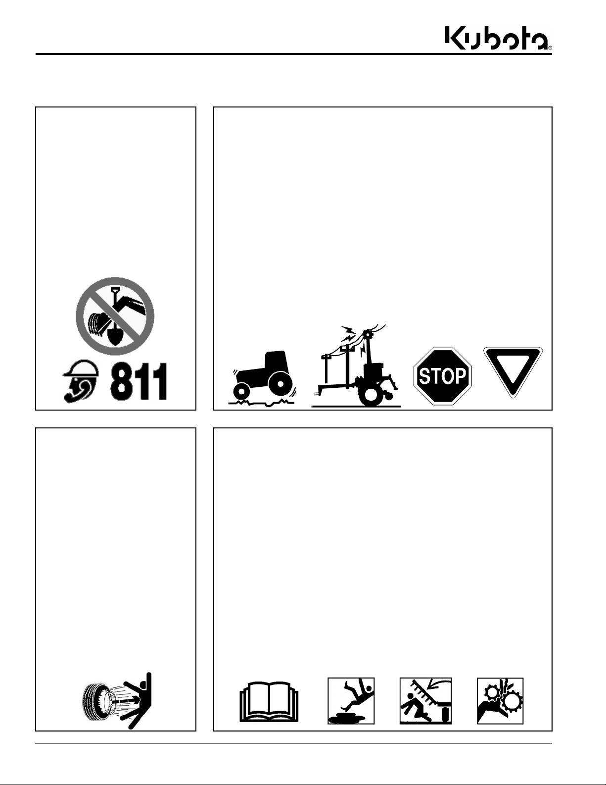
Dig Safe - Avoid
Underground Utilities
USA: Call 811
CAN: digsafecanada.ca
Always contact your local utility
companies (electrical, telephone,
gas, water, sewer, and others)
before digging so that they may
mark the location of any
underground services in the
area.
Be sure to ask how close you can
work to the marks they
positioned.
Transport Safely
Comply with federal, state, and
local laws.
Use towing vehicle and trailer of
adequate size and capacity. Secure
equipment towed on a trailer with
tie downs and chains.
Sudden braking can cause a towed
trailer to swerve and upset. Reduce
speed if towed trailer is not
equipped with brakes.
Avoid contact with any overhead
utility lines or electrically charged
conductors.
Always drive with load on end of
loader arms low to the ground.
Always drive straight up and down
steep inclines with heavy end of
skid steer or tractor with loader
attachment on the “uphill” side.
Engage park brake when stopped
on an incline.
Maximum transport speed for an
attached equipment is 20 mph. DO
NOT EXCEED. Never travel at a
speed which does not allow
adequate control of steering and
stopping. Some rough terrains
require a slower speed.
As a guideline, use the following
maximum speed weight ratios for
attached equipment:
20 mph when weight of attached
equipment is less than or equal
to the weight of machine towing
the equipment.
10 mph when weight of attached
equipment exceeds weight of
machine towing equipment but
not more than double the weight.
IMPORTANT: Do not tow a load
that is more than double the weight
of the vehicle towing the load.
Tire Safety
Tire changing can be dangerous
and must be performed by
trained personnel using the
correct tools and equipment.
Always maintain correct tire
pressure. Do not inflate tires
above recommended pressures
shown in the Operator’s Manual.
When inflating tires, use a clip-on
chuck and extension hose long
enough to allow you to stand to
one side and NOT in front of or
over the tire assembly. Use a
safety cage if available.
Securely support the attachment
when changing a wheel.
When removing and installing
wheels, use wheel handling
equipment adequate for the
weight involved.
Make sure wheel bolts have been
tightened to the specified torque.
Practice Safe Maintenance
Understand procedure before doing
work. Refer to the Operator’s Manual
for additional information.
Work on a level surface in a clean
dry area that is well-lit.
Lower attachment to the ground and
follow all shutdown procedures
before leaving the operator’s seat to
perform maintenance.
Do not work under any hydraulic
supported equipment. It can settle,
suddenly leak down, or be lowered
accidentally. If it is necessary to work
under the equipment, securely
support it with stands or suitable
blocking beforehand.
Use properly grounded electrical
outlets and tools.
Use correct tools and equipment for
the job that are in good condition.
Allow equipment to cool before
working on it.
Disconnect battery ground cable (-)
before servicing or adjusting
electrical systems or before welding
on equipment.
Inspect all parts. Make certain parts
are in good condition & installed
properly.
Replace parts on this attachment
with genuine Land Pride parts only.
Do not alter this attachment in a way
which will adversely affect its
performance.
Do not grease or oil attachment
while it is in operation.
Remove buildup of grease, oil, or
debris.
Always make sure any material and
waste products from the repair and
maintenance of the attachment are
properly collected and disposed.
Remove all tools and unused parts
before operation.
2
9/3/19
Page 7

Important Safety Information
Listed below are common practices that may or may not be applicable to the products
described in this manual.
Prepare for Emergencies
Be prepared if a fire starts.
Keep a first aid kit and fire
extinguisher handy.
Keep emergency numbers for
doctor, ambulance, hospital, and
fire department near phone.
911
Wear Personal Protective
Equipment (PPE)
Wear protective clothing and
equipment appropriate for the job
such as safety shoes, safety
glasses, hard hat, and ear plugs.
Clothing should fit snug without
fringes and pull strings to avoid
entanglement with moving parts.
Prolonged exposure to loud noise
can cause hearing impairment or
hearing loss. Wear suitable
hearing protection such as
earmuffs or earplugs.
Operating equipment safely
requires the operator’s full
attention. Avoid wearing
headphones while operating
equipment.
Avoid High
Pressure Fluids Hazard
Escaping fluid under pressure can
penetrate the skin causing serious
injury.
Relieve all residual pressure
before disconnecting hydraulic
lines or performing work on the
hydraulic system.
Make sure all hydraulic fluid
connections are tight and all
hydraulic hoses and lines are in
good condition before applying
pressure to the system.
Use a piece of paper or
cardboard, NOT BODY PARTS, to
check for suspected leaks.
Wear protective gloves and safety
glasses or goggles when working
with hydraulic systems.
DO NOT DELAY. If an accident
occurs, see a doctor familiar with
this type of injury immediately. Any
fluid injected into the skin or eyes
must be treated within
a few hours or
gangrene may
result.
Use Safety
Lights and Devices
Slow moving tractors, skid steers,
and self-propelled machines can
create a hazard when driven on
public roads. They are difficult to
see, especially at night. Use the
Slow Moving Vehicle (SMV) sign
when on public roads.
Flashing warning lights and turn
signals are recommended
whenever driving on public roads.
Use Seat Belt and ROPS
Land Pride recommends the use
of a CAB or roll-over-protectivestructures (ROPS) and seat belt
in almost all power machines.
Combination of a CAB or ROPS
and seat belt will reduce the risk
of serious injury or death if the
power machine should be upset.
If ROPS is in the locked-up
position, fasten seat belt snugly
and securely to help protect
against serious injury or death
from falling and machine
overturn.
Keep Riders Off
Machinery
Never carry riders on the power
machine or attachment.
Riders obstruct operator’s view
and interfere with the control of
the power machine.
Riders can be struck by objects or
thrown from the equipment.
Never use power machine or
attachment to lift or transport
riders.
9/3/19
3
Page 8

Important Safety Information
These are common practices that may or may not be applicable to the products described in
this manual.
Avoid crystalline Silica
(quartz) Dust
Because crystalline silica is a basic
component of sand and granite,
many activities at construction sites
produce dust containing crystalline
silica. Trenching, sawing, and boring
of material containing crystalline
silica can produce dust containing
crystalline silica particles. This dust
can cause serious injury to the
lungs (silicosis).
There are guidelines which should
be followed if crystalline silica
(quartz) is present in the dust.
Be aware of and follow OSHA
(or other local, State, or Federal)
guidelines for exposure to airborne
crystalline silica.
Know the work operations where
exposure to crystalline silica may
occur.
Participate in air monitoring or
training programs offered by the
employer.
Be aware of and use optional
equipment controls such as water
sprays, local exhaust ventilation,
and enclosed cabs with positive
pressure air conditioning if the
machine has such equipment.
Otherwise respirators shall be worn.
Where respirators are required, wear
a respirator approved for protection
against crystalline silica containing
dust. Do not alter respirator in any
way. Workers who use tight-fitting
respirators can not have beards/
mustaches which interfere with the
respirator seal to the face.
If possible, change into disposable
or washable work clothes at the
work site; shower and change into
clean clothing before leaving the
work site.
Do not eat, drink, use tobacco
products, or apply cosmetics in
areas where there is dust containing
crystalline silica.
Store food, drink, and personal
belongings away from the work
area.
Wash hands and face before eating,
drinking, smoking, or applying
cosmetics after leaving the exposure
area.
Handle
Chemicals Properly
Protective clothing should be
worn.
Handle all chemicals with care.
Follow instructions on container
label.
Agricultural chemicals can be
dangerous. Improper use can
seriously injure persons, animals,
plants, soil, and property.
Inhaling smoke from any type of
chemical fire can be a serious
health hazard.
Store or dispose of unused
chemicals as specified by the
chemical manufacturer.
Tractor Shutdown & Storage
Reduce engine speed and shut-off
all power to the attachment.
Park on solid, level ground and
lower attachment to ground or
onto support blocks.
Put tractor in park or set park
brake, turn off engine, and remove
switch key to prevent unauthorized
starting.
Relieve all hydraulic pressures.
Wait for all components to stop
before leaving operator’s seat.
Use steps, grab-handles and
anti-slip surfaces when stepping
on and off the tractor.
Detach and store implement in an
area where children normally do
not play. Secure implement using
blocks and supports.
OFF
R
E
M
O
V
E
Skid Steer Shutdown
And Storage
Reduce engine speed and shut-off
all power to the attachment.
Park on solid, level ground and
lower attachment until it is flat on
the ground or support blocks.
Turn off engine, and remove
switch key to prevent unauthorized
starting.
Relieve all hydraulic pressures.
If included, raise seat bar and
move controls until both lock.
Wait for all components to stop
before leaving operator’s seat.
Use steps, grab-handles and
anti-slip surfaces when stepping
on and off the skid steer.
Detach and store attachment in an
area where children normally do
not play. Secure attachment by
using blocks and supports.
OFF
R
E
M
O
V
E
4
9/3/19
Page 9

Important Safety Information
This page left blank intentionally.
9/3/19
5
Page 10
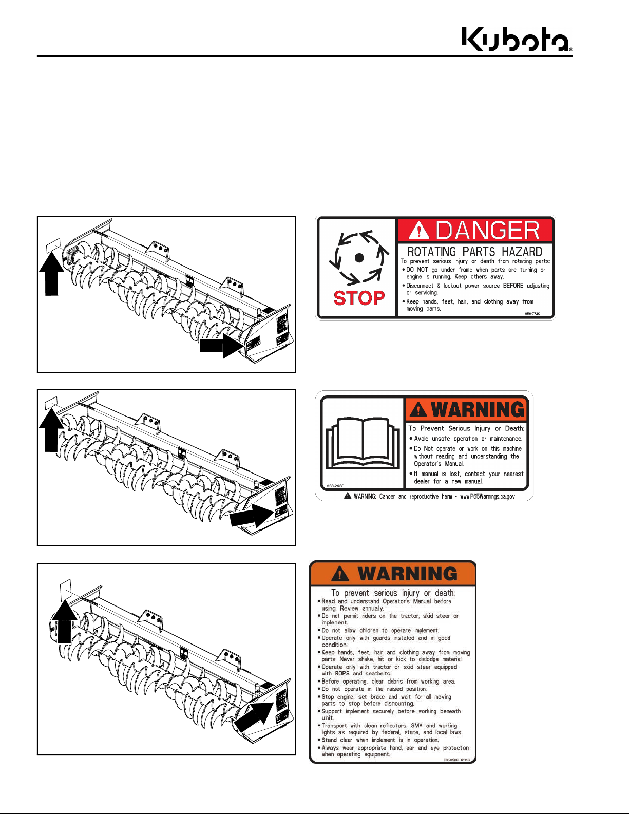
Table of Contents
Important Safety Information
Important Safety Information
Safety Labels
Your Silage Defacer comes equipped with all safety labels in
place. They are designed to help you safely operate your
attachment. Read and follow their directions.
1. Keep all safety labels clean and legible.
2. Refer to this section for proper label placement. Replace
all damaged or missing labels. Order new labels from your
nearest Kubota dealer. To find your nearest dealer, visit
our dealer locator at www.landpride.com.
3. Some new equipment installed during repair requires
safety labels to be affixed to the replaced component as
72155
specified by Kubota. When ordering new components make
sure the correct safety labels are included in the request.
4. Refer to this section for proper label placement.
To install new labels:
a. Clean surface area where label is to be placed.
b. Spray soapy water onto the cleaned area.
c. Peel backing from label and press label firmly onto the
surface.
d. Squeeze out air bubbles with edge of a credit card or
with a similar type of straight edge.
72156
72157
858-772C
DANGER: Rotating Parts Hazard
(2 Places) Located on the end of each frame arm.
838-293C
WARNING: Read Operator’s Manual
(2 Places) Located on the end of each frame arm.
818-858C
WARNING: Read
Operator’s Manual
(2 Places)
Located on the end
of each frame arm.
6
AP-SD96 Silage Defacer 350-270MK 9/3/19
Page 11
Important Safety Information
Table of Contents
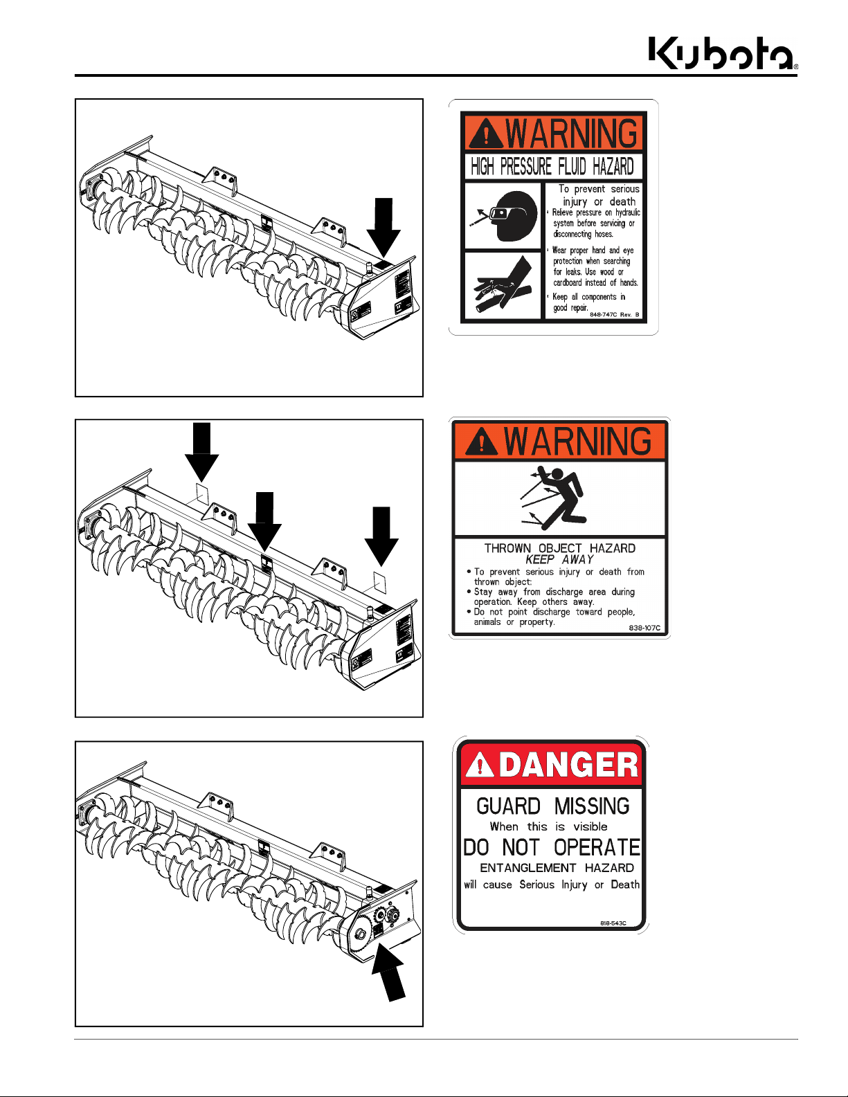
72158
848-747C
WARNING: High Pressure Fluid Hazard
(1 Place) Located on the left, top side of frame.
72159
72160
838-107C
WARNING: Thrown Object Hazard
(3 Places) Located on the front and back side of frame
tube.
818-543C
DANGER: Guard Missing
(1 Place) Located inside gear housing of left frame arm.
AP-SD96 Silage Defacer 350-270MK9/3/19
7
Page 12

Table of Contents
Introduction
Introduction
Kubota welcomes you to the growing family of new
product owners. The Silage Defacer has been designed
with care and built by skilled workers using quality
materials. Proper assembly, maintenance, and safe
operating practices will help you get years of satisfactory
use from this product.
Application
The Silage Defacer is designed and built by Kubota by
Land Pride. This attachment efficiently loosens and
breaks apart tightly packed or frozen silage and other
feeds, while leaving the face of the bunker evenly
groomed, minimizing spoilage. Additional design
features include curved tines welded in a spiral
orientation to keep the rotor from bouncing off the face of
the bunker, and a frame designed around providing
beneficial visibility to the operator. The 96" (2.4m) wide
Silage Defacer will meet the needs of owners and
operator’s having skid steers, track loaders, or tractors
equipped with a front loader having a hydraulic flow
capacity rating of 12 to 25 gpm (45 to 95 Lpm) at
1500 - 3500 psi (10.3 - 24.1 MPa). This attachment is
available with two hitch options: A quick attach hitch
extension and a Euro hitch extension.
See “Specifications & Capacities” on page 24 and
“Features & Benefits” on page 26 for additional
information and performance enhancing options.
Owner Assistance
The Online Warranty Registration should be completed
by the dealer at the time of purchase. This information is
necessary to provide you with quality customer service.
The parts on your Silage Defacer have been specially
designed by Kubota/Land Pride and should only be
replaced with genuine Kubota parts. Contact a Kubota
dealer if customer service or repair parts are required.
Your Kubota dealer has trained personnel, repair parts,
and equipment needed to service this attachment.
Serial Number
For quick reference and prompt service, record model
and serial number on the inside cover page and again on
the warranty page. Always provide model number and
serial number when ordering parts and in all
correspondences with your Kubota dealer. For location of
your serial number plate, see Figure 1.
72163
Using This Manual
•
This Operator’s Manual is designed to help familiarize
you with safety, assembly, operation, adjustments,
troubleshooting, and maintenance. Read this manual
and follow the recommendations to help ensure safe
and efficient operation.
• The information contained within this manual was
current at the time of printing. Some parts may change
slightly to assure you of the best performance.
• To order a new Operator’s or Parts Manual, contact
your authorized dealer. Manuals can also be
downloaded, free-of-charge, from our website at
www.landpride.com
Terminology
“Right” or “Left” as used in this manual is determined by
facing the direction the machine will operate while in use
unless otherwise stated.
Definitions
IMPORTANT: A special point of information related
to the following topic. Kubota’s intention is this
information must be read & noted before continuing.
NOTE: A special point of information that the
operator should be aware of before continuing.
AP-SD96 Serial Number Plate Location
Figure 1
Further Assistance
Your dealer wants you to be satisfied with your new
Silage Defacer. If for any reason you do not understand
any part of this manual or are not satisfied with the
service received, the following actions are suggested:
1. Discuss any problems you have with your attachment
with your dealership service personnel so they can
address the problem.
2. If you are still not satisfied, seek out the owner or
general manager of the dealership, explain the
question/problem, and request assistance.
3. For further assistance write to:
Kubota by Land Pride
Service Department
1525 East North Street
P.O. Box 5060
Salina, Ks. 67402-5060
E-mail address
lpservicedept@landpride.com
8
AP-SD96 Silage Defacer 350-270MK 9/3/19
Page 13

Table of Contents
Section 1: Optional Equipment & Set-up
Section 1: Optional Equipment & Set-up
Skid Steer/Tractor Requirements
The Silage Defacer is designed to attach to skid steers,
track loaders, and tractors equipped with a front loader
meeting the following requirements:
Hitch types . . . . . . . . Quick attach hitch or Euro hitch
Max. hydraulic pressure rating . . .3500 psi (24.1MPa)
Hydraulic flow rate . . . . . 12 to 25 gpm (45 to 95 Lpm)
Hydraulic outlets
Skid steer/track loader . . . . . . . . . 1 male/1 female
Tractor or tractor loader. . . . . . . . . . . . . . . . . . . . . .
. . . . . . . . . . . Dependent on tractor loader valve kit
Skid steer weight . . . . . . . . . . . . . See Warning below
Rear-view mirror . . . . . . . . . . . . . . . . . Recommended
!
WARNING
To avoid serious injury or death:
• Consult your power machine’s manual for operating
capacity, lifting capacity, and operating specifications.
Exceeding rated capacities and specifications can result in
a roll-over or other serious hazard.
• Lightweight power machines may need weight added to the
rear to maintain steering control and prevent forward
tipping or side tipping caused by a heavy front load. Consult
your power machine Operator’s Manual to determine
proper weight requirements and maximum weight
limitations.
Torque Requirements
Refer to “Torque Values Chart” on page 28 to determine
correct torque values when tightening hardware.
Before You Start
!
WARNING
To avoid serious injury or death:
Allow only persons to operate this attachment who have fully
read and comprehended this manual, who are properly trained
to operate the attachment safely, and who are age 16 or older.
Serious injury or death can result from the failure to read,
understand, and follow instructions provided in this manual.
Make sure the intended power machine of use conforms
to the “Skid Steer/Tractor Requirements” stated above.
Read and understand the Operator’s Manual for your
Silage Defacer. An understanding of how it works will aid
in the assembly and setup of your attachment.
Go through the “Assembly Checklist” on this page
before assembling the Silage Defacer. Speed up your
assembly task and make the job safer by having all
needed parts and equipment readily at hand.
Assembly Checklist
Check Reference
Have a forklift or loader with properly sized chains and safety
stands capable of lifting and supporting the equipment on hand.
Have a minimum of two people available during assembly.
Double check to make sure all parts and
fasteners are accounted for and installed in the
correct location to lessen the chance of using a
bolt incorrectly. Refer to the Parts Manual if
unsure.
NOTE: All assembled hardware from the
factory has been installed in the correct
location. Remember location of a part or
fastener if removed. Keep parts separated.
Make sure working parts move freely and
hardware is installed and tightened
accordingly.
Make sure all safety labels are correctly
located and legible. Replace if damaged.
Make sure all grease fittings are in place and
lubricated.
Operator’s
Manual
350-270MK
Parts Manual
350-270PK
Operator’s
Manual
350-270MK
Page 6
Page 23
Power Machine Shutdown Procedure
The following are basic power machine shutdown
procedures. Follow these procedures and any additional
shutdown procedures provided in your power machine’s
Operator’s Manual before leaving the operator’s seat.
1. Reduce engine speed and shut-off all power to the
attachment.
2. Park on solid, level ground and lower attachment until
it is flat on the ground or on non-concrete support
blocks.
3. If shutting down a tractor, put tractor in park or set
park brake.
4. Turn off engine, and remove switch key to prevent
unauthorized starting.
5. Relieve all hydraulic pressures.
6. If included, raise seat bar and move controls until
both lock.
7. Wait for all components to come to a complete stop
before leaving the operator’s seat.
8. Use steps, grab-handles, and anti-slip surfaces
when stepping on and off the power machine.
AP-SD96 Silage Defacer 350-270MK9/3/19
9
Page 14

Table of Contents
Section 1: Optional Equipment & Set-up
Place lifting strap #1 here
72164
Place lifting strap #3 here
Quick Attach Hitch & Euro Hitch Assembly
Figure 1-1
Hitch Assembly Options
Kubota offers two hitch options for the Silage Defacer. To
be compatible with this attachment, skid steers, track
loaders, and tractors must have a front loader equipped
with a quick attach hitch plate or Euro hitch plate.
Quick Attach Hitch . . . . . . . . . . . . . . . . . . . 350-260A
Euro Hitch . . . . . . . . . . . . . . . . . . . . . . . . . . 350-239A
!
DANGER
To avoid serious injury or death:
• Always secure equipment with solid, non-concrete supports
before working under it. Never go under equipment
supported by concrete blocks or hydraulics. Concrete can
break, hydraulic lines can burst, and/or hydraulic controls
can be actuated even when power to hydraulics is off.
• Keep all persons and objects clear while any part of the
machine is in motion. A person can be pinched or crushed
by the machine.
Refer to Figure 1-1:
1. On a flat surface, place solid, non-concrete supports
under the left and right arm of rotor frame (#2).
Ensure rotor frame (#2) is level to the ground.
2. While wearing gloves, use a rag to wipe down the
face of all mounting plates (#7 & #8) to clear away
debris.
Place lifting strap #2 here
3. Using a hoist or power machine, lift hitch
frame (#1A or #1B) and align mounting plates (#7) to
mounting plates (#8) on rotor frame (#2).
a. If using a hoist, use a minimum of three lifting
straps to secure frame at locations shown in
Figure 1-1.
b. If using a power machine and loader equipped
with a quick attach hitch plate to lift hitch
frame (#1A), refer to “Hook-up to Quick Attach
Hitch” on page 16 for proper hook-up.
c. If using a power machine and loader equipped
with a Euro hitch plate to lift hitch frame (#1B),
refer to“Hook-up to Euro Hitch” on page 17 for
proper hookup.
d. If using a forklift, slide forks below the underside
of hitch frame (#1A or #1B) and bottom frame
spacer (#9). Secure frame to forks before moving
forklift.
4. Attach rotor frame (#2) to hitch frame (#1A or #1B) by
inserting 1/2" x 1 3/4" GR5 bolts (#3) through frame
mounting plates (#7 & #8) on hitch and rotor frames.
5. Place flat washers (#6) and lock washers (#5) on all
twelve 1/2" x 1 3/4" GR5 bolts (#3), then secure with
1/2" hex nuts (#4). Tighten 1/2" hex nuts (#4) to the
correct torque by referring to “Section 8: Torque
Values Chart” on page 28.
6. Once all twelve 1/2" GR5 bolts (#3) have been
tightened to the correct torque, ensure there are no
visible gaps between frame mounting
plates (#7 & #8).
10
AP-SD96 Silage Defacer 350-270MK 9/3/19
Page 15

Table of Contents
Section 1: Optional Equipment & Set-up
72177
Detail A
72176
Skid steer
hose stay
Skid Loader Hose Kit Assembly
Figure 1-2
Skid Loader Hose Kit Assembly
Skid Loader Hose Kit . . . . . . . . . . . . . . . . . 350-269A
!
WARNING
To avoid serious injury or death:
• Hydraulic fluid under high pressure can penetrate the skin
and/or eyes causing a serious injury. Wear protective gloves
and safety glasses or goggles when working with hydraulic
systems. Use a piece of cardboard or wood rather than
hands when searching for leaks. A doctor familiar with this
type of injury must treat the injury within a few hours or
gangrene may result. DO NOT DELAY.
• Shut power machine down and release all hydraulic
pressure to the equipment before connecting or
disconnecting hydraulic hoses to or from the power
machine.
Refer to Figure 1-2:
1. Attach elbow fitting (#4) to top port of hydraulic motor
(#3). Attach elbow fitting (#5) to bottom port of
hydraulic motor (#3).
2. Attach in-line valve fitting (#6) to elbow fitting (#5).
3. Attach and tighten female ends of hydraulic
hoses (#1 & #2) to hydraulic fittings (#4 & #6),
respectively.
4. Remove hose cover (#12), hose clamp brackets (#13)
and all hardware items (#9, #10, & #11) from
welded hex bolts (#7) found on the left side of hitch
frame (#14). Keep removed hardware close by.
5. Route hydraulic hoses (#1 & #2) from hydraulic
motor (#3), to the welded hex bolt (#7) closest to
hydraulic motor (#3).
6. Place hydraulic hose (#1) above hex bolt (#7) and
hydraulic hose (#2) below hex bolt (#7).
7. Secure hydraulic hoses (#1 & #2) by fastening hose
clamp bracket (#13), lock washer (#10) and 1/4" hex
nut (#11) to hex bolt (#7). Tighten hex nut (#11) to the
correct torque. Refer to “Section 8: Torque Values
Chart” on page 28.
8. Continue routing hydraulic hoses (#1 & #2) along side
of hitch frame (#14). Repeat steps 6 and 7 to secure
hoses at second welded hex bolt (#7) found on left
side of hitch frame (#14).
9. Secure hose cover (#12) to both welded hex
bolts (#7) with flat washers (#9), lock washers (#10),
and 1/4" hex nuts (#11). Tighten hex nuts (#11) to the
correct torque.
10. Route hydraulic hoses (#1 & #2) through the hose
stay found on the skid steer or track loader.
11. Thread female quick coupler (#1A) onto male end of
hydraulic hose (#1). Thread male quick coupler (#2A)
onto male end of hydraulic hose (#2).
12. The Silage Defacer is now ready to hook-up to a skid
steer or track loader.
AP-SD96 Silage Defacer 350-270MK9/3/19
11
Page 16

Table of Contents
Section 1: Optional Equipment & Set-up
72171
72170
Detail A
72613
Detail B
Tractor Loader Hose Kit Assembly
Figure 1-3
Tractor Loader Hose Kit Assembly
Tractor Loader Hose Kit . . . . . . . . . . . . . . . 350-267A
!
WARNING
To avoid serious injury or death:
• Hydraulic fluid under high pressure can penetrate the skin
and/or eyes causing a serious injury. Wear protective gloves
and safety glasses or goggles when working with hydraulic
systems. Use a piece of cardboard or wood rather than
hands when searching for leaks. A doctor familiar with this
type of injury must treat the injury within a few hours or
gangrene may result. DO NOT DELAY.
• Shut power machine down and release all hydraulic
pressure to the equipment before connecting or
disconnecting hydraulic hoses to or from the power
machine.
Refer to Figure 1-3:
1. Attach elbow fitting (#4) to top port of hydraulic motor
(#3). Attach elbow fitting (#5) to bottom port of
hydraulic motor (#3).
2. Attach in-line valve fitting (#6) to elbow fitting (#5).
3. Attach and tighten female ends of hydraulic
hoses (#1 & #2) to hydraulic fittings (#4 & #6),
respectively.
4. Remove hose cover (#12), hose clamp brackets (#13)
and all hardware items (#9, #10, & #11) from welded
hex bolts (#7) found on the left side of hitch
frame (#14). Keep removed hardware close by.
5. Route hydraulic hoses (#1 & #2) from hydraulic
motor (#3), to the welded hex bolt (#7) closest to
hydraulic motor (#3).
6. Place hydraulic hose (#1) above hex bolt (#7) and
hydraulic hose (#2) below hex bolt (#7).
7. Secure hydraulic hoses (#1 & #2) by fastening hose
clamp bracket (#13), lock washer (#10) and hex
nut (#11) to hex bolt (#7). Tighten hex nut (#11) to the
correct torque. Refer to “Section 8: Torque Values
Chart” on page 28.
8. Continue routing hydraulic hoses (#1 & #2) along side
of hitch frame (#14). Repeat steps 6 and 7 to secure
hoses at second welded hex bolt (#7) found on left
side of hitch frame (#14).
9. Secure hose cover (#12) to both welded hex
bolts (#7) with flat washers (#9), lock washers (#10),
and 1/4" hex nuts (#11). Tighten hex nuts (#11) to the
correct torque.
10. Route hydraulic hoses (#1 & #2) between upper and
lower tubes of hitch frame (#14)
11. Secure hydraulic hoses (#1 & #2) to welded hex bolt
(#7) on hitch frame center tube (#15) with hose clamp
bracket (#13), flat washer (#9), lock washer (#10),
and 1/4" hex nut (#11). Tighten hex nut (#11) to the
correct torque. See detail B.
12. Route hydraulic hoses (#1 & #2) through formed
D-ring (#8).
13. Thread quick disconnect male fitting (#1A) onto male
end of hydraulic hose (#1). Thread quick disconnect
female fitting (#2A) onto male end of hydraulic
hose (#2).
14. The Silage Defacer is now ready to hook-up to a
tractor with a compatible front loader.
12
AP-SD96 Silage Defacer 350-270MK 9/3/19
Page 17
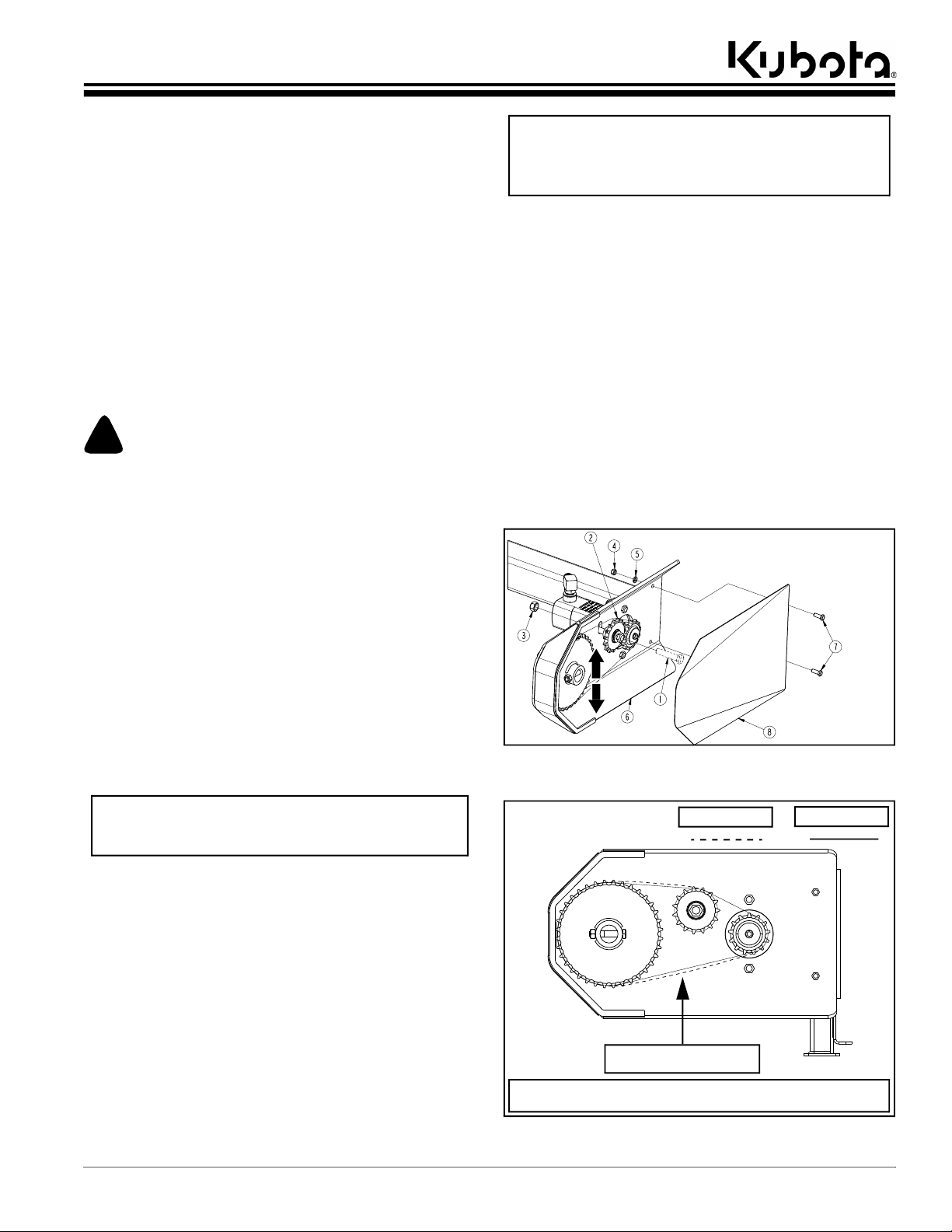
Table of Contents
Section 2: Adjustments
Section 2: Adjustments
Checking & Adjusting Rotor Chain Tension
Over time, the use of your Silage Defacer may require
adjusting the tension on the rotor chain. Be sure to check
the tension periodically to maintain your attachment’s top
performance. Too much slack in the chain can cause
excessive chain deflection, diminishing the defacing
capabilities of the rotor. Excessive tension on the chain
can place stress on the hydraulic motor and sprockets,
leading to accelerated and premature wear of the drive
components.
Before making adjustments to the chain, lower the Silage
Defacer to the ground, then relieve all hydraulic pressure
from the auxiliary hydraulic lines connected to the
attachment. Proceed with properly shutting down the
power machine by following the “Power Machine
Shutdown Procedure” on page 9.
!
WARNING
To avoid serious injury or death:
• Hydraulic fluid under high pressure can penetrate the skin
and/or eyes causing a serious injury. Wear protective gloves
and safety glasses or goggles when working with hydraulic
systems. Use a piece of cardboard or wood rather than
hands when searching for leaks. A doctor familiar with this
type of injury must treat the injury within a few hours or
gangrene may result. DO NOT DELAY.
• Shut power machine down and release all hydraulic
pressure to the equipment before connecting or
disconnecting hydraulic hoses to or from the power
machine.
• Hydraulic fluid and components that the fluid flows through
such as couplers, hoses, hydraulic lines, fittings and motor
become hot from use. Be careful when connecting and
disconnecting couplers. It is best to allow hydraulic fluid
and hydraulic components to cool before touching them.
• All guards and shields must be installed and in good
working condition while operating the attachment.
NOTE: 5/8" x 3" bolt (#1) and 5/8" hex nut (#3) are
exploded for illustration purposes only in Figure 2-1.
Do not remove bolt (#1) or hex nut (#3) from idler
sprocket (#2) when adjusting chain tension.
6. Loosen 5/8" hex nut (#3) from 5/8" GR5 bolt (#1).
Do not remove hex nut (#3) from bolt (#1).
7. Move idler sprocket (#2) up in slotted hole to increase
tension on rotor chain. Move idler sprocket (#2) down
in slotted hole to decrease tension on rotor chain.
8. When adjusting tension on rotor chain, ensure chain
deflection does not exceed a 1/4" or fall below 1/8".
See Figure 2-2.
9. When correct tension has been achieved, retighten
5/8" hex nut (#3) to the 5/8" GR5 bolt (#1) to the
correct torque, by referring to “Section 8: Torque
Values Chart” on page 28.
10. Enclose sprockets and rotor chain by replacing chain
guard (#8) onto left rotor frame arm (#6) with both 3/
8" x 1" bolts (#7), and secure with 3/8" lock washers
(#5), and 3/8" locknuts (#4). Do not overtighten
locknuts (#4).
72591
Rotor Chain Tension Adjustment
Figure 2-1
IMPORTANT: Chain deflection is determined by how
far the rotor chain moves from its original position
after pushing up or down on the chain links.
Refer to Figure 2-1:
1. Shut down the power machine before dismounting by
following the “Power Machine Shutdown
Procedure” on page 9.
2. With attachment resting on the ground, operate the
hydraulic control levers to release all hydraulic
system pressure from loader arm lift cylinders, and
hitch tilt cylinders.
3. Disconnect hydraulic hose couplers from power
machine.
4. Remove both 3/8" locknuts (#4), 3/8" lock
washers (#5), and 3/8" x 1" bolts (#7) from chain
guard (#8) and left rotor frame arm (#6). Now remove
chain guard (#8).
5. Check tension and chain deflection on the rotor
chain. See Figure 2-2.
72593
Check tension and chain
Chain deflection is determined by how far the rotor chain moves from its
original position after pushing up or down on the chain links.
Rotor Chain Tension Guideline
Chain Deflection
deflection here
Figure 2-2
AP-SD96 Silage Defacer 350-270MK9/3/19
Rotor Chain
13
Page 18

Section 3: Operating
Table of Contents
Section 3: Operating
Startup Checklist
Hazard control and accident prevention are dependent
upon the awareness, concern, prudence, and proper
training involved in the operation, transport, storage, and
maintenance of the Silage Defacer. Therefore, it is
absolutely essential that no one operates the Silage
Defacer without first having read, fully understood, and
become totally familiar with the Operator’s Manual. Make
sure the operator has paid particular attention to:
• Important Safety Information, page 1
• Section 1: Optional Equipment & Set-up, page 9
• Section 2: Adjustments, page 13
• Section 3: Operating, page 14
• Section 4: Maintenance & Lubrication, page 22
Perform the following inspections before using your
Silage Defacer.
Operating Checklist
Read and follow all safety rules carefully.
Refer to “Important Safety Information”.
Make sure there are no hydraulic leaks. Refer
to “Avoid High Pressure Fluids Hazard”.
Read and follow all safety notices. Refer to
“Section 3: Operating”.
Confirm attachment is properly hooked up to
power machine.
Confirm chain guard is secured in place and
in good working condition.
Read and follow all maintenance instructions.
See “Section 4: Maintenance & Lubrication”.
Check attachment initially and periodically for
loose hardware. See “Section 8: Torque
Values Chart”.
Check Page
1
3
14 &15
16 & 17
19
22
28
Safety Information
!
DANGER
To avoid serious injury or death:
• Do not allow bystanders or animals to be near the
attachment, loader arms, or power machine during
operation. Stop operation if bystanders are too close. They
can be hit by thrown or falling objects, entangled, crushed,
ran over, etc.
• A crushing hazard exists while hooking-up and unhooking
with a quick attach hitch or Euro hitch. Check hitch fit-up
frequently. Do not allow anyone to stand between
attachment and power machine while approaching or
backing away from the attachment. Do not operate lift and/
or tilt controls while someone is near the power machine
and/or attachment.
• Keep attachment and/or loader arms away from overhead
electrical power lines. Place an orange warning sign under
overhead lines indicating type of danger above.
• Always secure equipment with solid, non-concrete supports
before working under it. Never go under equipment
supported by concrete blocks or hydraulics. Concrete can
break, hydraulic lines can burst, and/or hydraulic controls
can be actuated even when power to hydraulics is off.
• Do not let children play on or around the attachment
including when stored. Children and/or attachment can fall.
!
WARNING
To avoid serious injury or death:
• Allow only persons to operate this attachment who have
fully read and comprehended this manual, who are properly
trained to operate the attachment safely, and who are age 16
or older. Serious injury or death can result from the failure
to read, understand, and follow instructions provided in this
manual.
• Never carry riders on the attachment or power machine.
Riders can obstruct the operator’s view, interfere with
controls, be pinched by moving components, become
entangled in rotating components, struck by objects, thrown
about, fall off and be run over, etc.
• Hydraulic fluid under high pressure can penetrate the skin
and/or eyes causing a serious injury. Wear protective gloves
and safety glasses or goggles when working with hydraulic
systems. Use a piece of cardboard or wood rather than
hands when searching for leaks. A doctor familiar with this
type of injury must treat the injury within a few hours or
gangrene may result. DO NOT DELAY.
• Backup alarm must be in good working order to warn
others. Use a backup camera or rear-view mirror that is in
good condition to help see undesirable situations behind the
unit. Drive at a slower speed to compensate for blind spots.
• Operate only power machines equipped with a certified
Roll-Over Protective Structure (ROPS) and seat belt. Keep
folding ROPS in the “locked up” position when
appropriate. If ROPS is in the locked up position, fasten seat
belt snugly and securely to help protect against serious
injury or death from falling and machine overturn.
• Always be alert when operating the loader. Watch the front,
sides, and back for people, animals, and obstructions.
Watch for overhead clearances when raising loader arms
and while traveling.
• Perform scheduled maintenance. Check for loose
hardware, missing parts, broken parts, structural cracks,
and excessive wear. Make repairs before putting the
attachment back into service. Serious breakdowns can
result in injury or death.
• Do not alter attachment or replace parts on the attachment
with other brands. Other brands may not fit properly or
meet OEM specifications. They can weaken the integrity
and impair the safety, function, performance, and life of the
attachment. Replace parts only with genuine OEM parts.
• Dress properly for the job. Do not wear loose fitting
clothing or clothing with pull strings. Keep long hair tucked
in. Clothing and hair can become entangled in rotating
components. Wear footwear that will improve footing on
slippery surfaces.
14
AP-SD96 Silage Defacer 350-270MK 9/3/19
Page 19
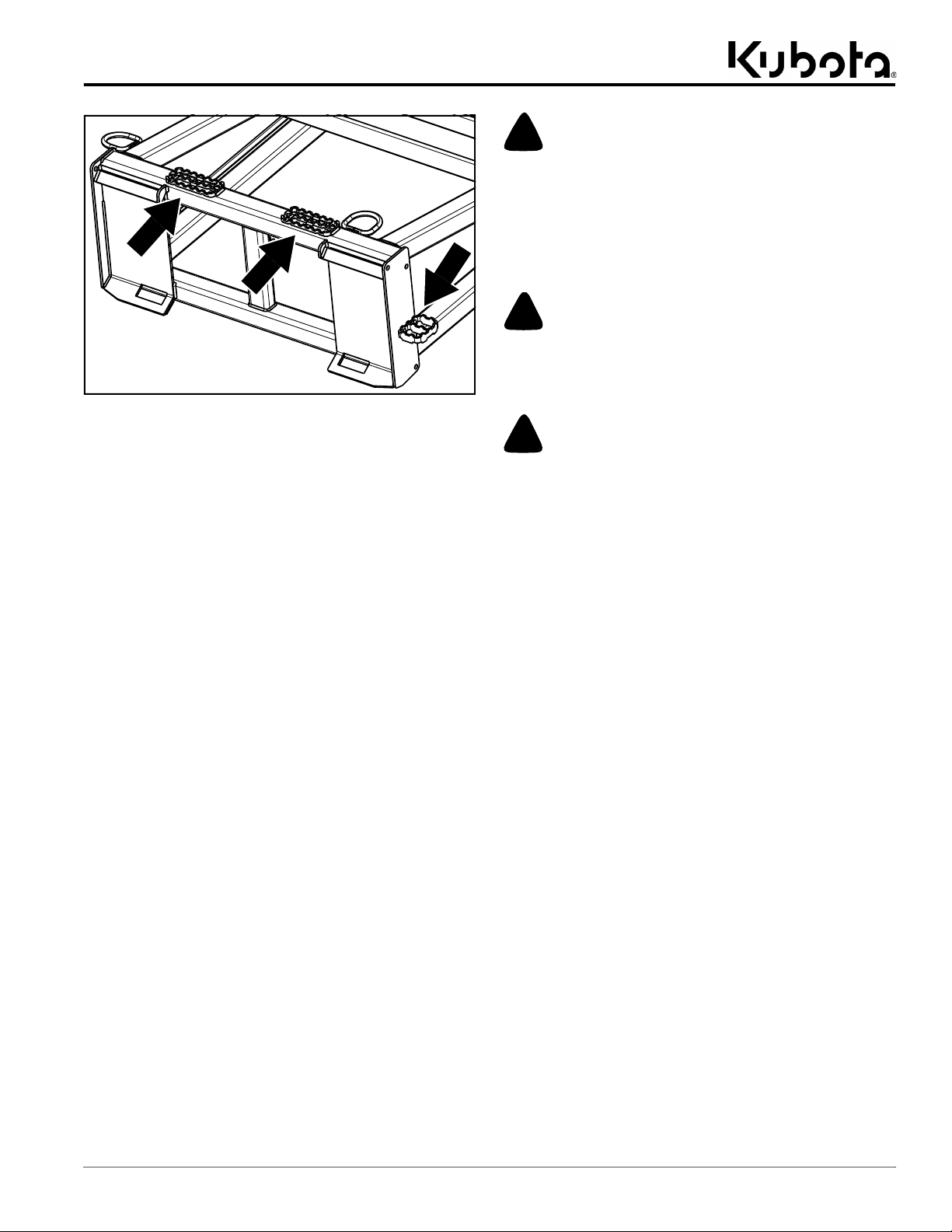
Table of Contents
Section 3: Operating
72600
Anti-Slip Surfaces (Quick Attach Hitch Only)
Figure 3-1
• Refer to Figure 3-1: Use steps, grab-handles, and anti-
slip surfaces on the power machine and attachment to get on
and off the power machine. Using unapproved stepping
surfaces and/or handholds can result in a falling hazard.
• All guards and shields must be installed and in good
working condition while operating the attachment.
• Avoid hitting solid objects with this attachment. Solid
objects can damage equipment and throw operator forward
causing loss of control, bodily injury, or death. Always wear
the seat belt.
• Do not use attachment as a lifting device for people or as a
work platform. It is not properly designed or guarded for
this use.
• Do not use attachment for pulling objects out of the ground,
for prying other objects, or for pushing and towing other
equipment.
• Do not use attachment to lift the front or back of the power
machine off the ground. Doing so can damage the
attachment, power machine, and/or cause serious injury or
death.
• Only use the Silage Defacer to deface silage and similar
feeds. Using the attachment in a manner other than its
designed purpose will result in damage to the unit as well as
unforeseen objects being thrown from the rotor.
• Make sure controls are all in neutral position or park before
starting the power machine.
• Never adjust skid steer relief valve for a pressure rating
higher than what is recommended by the skid steer
manufacturer.
• Make sure hydraulic hoses are properly routed without
twists to prevent becoming stretched, pinched, or kinked. A
damaged hydraulic hose can burst and leak hydraulic fluid.
• Hydraulic fluid and components that the fluid flows through
such as couplers, hoses, hydraulic lines, fittings and motor
become hot from use. Be careful when connecting and
disconnecting couplers. It is best to allow hydraulic fluid
and hydraulic components to cool before touching them.
!
CAUTION
To avoid minor or moderate injury:
• Do not allow bystanders to be in the area when power
machine and attachment are in use. They can be hit with
flying debris such as silage or other unforeseen foreign
objects.
Transport Safety
!
DANGER
To avoid serious injury or death:
• Keep attachment, loader arms, and/or load away from
overhead electrical power lines. Place an orange warning
sign under overhead lines indicating type of danger above.
!
WARNING
To avoid serious injury or death:
• Always exercise safety, courtesy, and common sense. Be
aware of pedestrian and vehicle traffic. Check blind spots
before moving equipment.
• Always transport with attachment carried low to protect
against rollover, hitting overhead objects, power lines, and
loss of control.
• When transporting a skid steer or track loader on a trailer,
use towing vehicle and trailer of adequate size and capacity.
Always drive up a ramp with heavy end uphill. Engage the
power machine’s park brake and remove ignition switch key
once it is loaded. Secure power machine and attachment
using tie downs and chains.
AP-SD96 Silage Defacer 350-270MK9/3/19
15
Page 20

Section 3: Operating
72596
Table of Contents
Hook-up to Quick Attach Hitch
Figure 3-2
Hook-up to Quick Attach Hitch
!
DANGER
To avoid serious injury or death:
• A crushing hazard exists while hooking-up and unhooking
to and from a quick attach hitch. Do not allow anyone to
stand between attachment and power machine while
approaching or backing away from the attachment. Do not
operate lift and/or tilt controls while someone is near the
power machine and/or attachment.
!
WARNING
To avoid serious injury or death:
• Check quick attach hitch fit-up frequently to ensure it is
properly secured under the attachment’s top hitch hook bars
and lock pins are fully extended into hitches lower slots. An
improper fit-up can cause the attachment to come loose
from the loader hitch plate and fall.
IMPORTANT: This attachment can only be attached
to and used with skid steers, track loaders, and
tractor front loaders equipped with a universal quick
attach hitch that meets SAE standards.
Refer to Figure 3-2:
1. Check for and remove any debris on the power
machine’s front loader and the Silage Defacer’s hitch
point areas before hooking up to the attachment.
a. Pay special attention to the underside of
attachment’s top hitch hook bars (#4).
2. Check hitch plates for structural cracks as well as
bent or deformed components.
3. Carefully and slowly drive up to the attachment hitch
plates (#6). Ensure the loader’s quick attach hitch is
aligned and parallel with the attachment’s top hitch
hook bars (#4).
4. Tilt top of loader’s quick attach hitch slightly forward.
5. Place the top of loader’s quick attach hitch under
attachment’s top hitch hook bars (#4) and slowly
raise loader’s quick attach hitch up until its top edge
is properly hooked under the attachment’s top hitch
hook bars (#4).
6. Slowly tilt top of loader’s quick attach hitch back until
the attachment’s hitch plates (#6) make full contact
with the face of the loader’s quick attach hitch.
7. Shut down the power machine before dismounting by
following the “Power Machine Shutdown
Procedure” on page 9.
8. Push down lock handles on the loader’s quick attach
hitch, ensuring lock pins go through lower slots (#5)
on both hitch plates (#6). Confirm lock handles are
locked in position.
9. Once attachment is properly secured to power
machine, proceed to “Hydraulic Hook-up to Power
Machine” on page 18.
16
AP-SD96 Silage Defacer 350-270MK 9/3/19
Page 21

Section 3: Operating
72597
Table of Contents
Hook-up to Euro Hitch
Figure 3-3
Hook-up to Euro Hitch
!
DANGER
To avoid serious injury or death:
• A crushing hazard exists while hooking-up and unhooking
to and from a Euro hitch. Do not allow anyone to stand
between attachment and power machine while approaching
or backing away from the attachment. Do not operate lift
and/or tilt controls while someone is near the power
machine and/or attachment.
!
WARNING
To avoid serious injury or death:
• Check Euro hitch fit-up frequently to ensure it is properly
secured under the attachment’s hitch hooks and lock pins
are fully extended into the locking lugs. An improper fit-up
can cause the attachment to come loose from the loader
hitch plate and fall.
IMPORTANT: This attachment can only be attached
to tractor front loaders equipped with a Euro hitch
plate.
Refer to Figure 3-3:
1. Check hitch plates for structural cracks as well as
bent or deformed components.
2. Lower the loader’s Euro hitch plate down as far as
possible.
3. If required, manually pull lock handle on loader’s
Euro hitch plate until lock pins are fully back and
ready for hook-up.
4. Carefully drive up to the attachment hitch
plates (#5) until mounting bar on loader’s Euro hitch
plate is aligned and positioned under hitch plate
hooks (#4). It may be necessary to tilt top of loader’s
Euro hitch plate forward.
5. Raise loader’s Euro hitch plate up until mounting bar
is completely caught under the upper hitch
hooks (#4).
6. Slowly tilt top of loader’s Euro hitch plate back to
allow the attachment’s lower hitch lugs (#6) to
swing-in against the loader’s Euro hitch plate. If
necessary, raise loader’s Euro hitch plate up to
complete the swing-in alignment.
7. If Euro hitch pins do not auto-lock into the lower hitch
lugs (#6), shut down power machine before
dismounting by following the “Power Machine
Shutdown Procedure” on page 9.
8. Dismount power machine and manually operate
loader’s Euro hitch lever to push lock pins into lower
hitch lugs (#6).
9. Verify that the lever is locked into position to keep
lock pins from backing out of lock pin holes on lower
hitch lugs (#6).
10. Once attachment is properly secured to power
machine, proceed to “Hydraulic Hook-up to Power
Machine” on page 18.
AP-SD96 Silage Defacer 350-270MK9/3/19
17
Page 22

Section 3: Operating
Table of Contents
Hydraulic Hook-up to Power Machine
Kubota offers two hose kit options for the Silage Defacer.
The skid loader hose kit is to be hooked up to a skid steer
or track loader, while the tractor loader hose kit is to be
hooked up to the front loader of a tractor.
!
WARNING
To avoid serious injury or death:
• Make sure hydraulic hoses are properly routed without
twists to prevent becoming stretched, pinched, or kinked. A
damaged hydraulic hose can burst and leak hydraulic fluid.
• Hydraulic fluid under high pressure can penetrate the skin
and/or eyes causing a serious injury. Wear protective gloves
and safety glasses or goggles when working with hydraulic
systems. Use a piece of cardboard or wood rather than
hands when searching for leaks. A doctor familiar with this
type of injury must treat the injury within a few hours or
gangrene may result. DO NOT DELAY.
• Shut power machine down and release all hydraulic
pressure to the equipment before connecting or
disconnecting hydraulic hoses to or from the power
machine.
• Always be alert when operating the loader. Watch the front,
sides, and back for people, animals, and obstructions.
Watch for overhead clearances when raising loader arms
and while traveling.
Tractor Loader Hose Kit Hook-up
Refer to Figure 3-5:
1. Shutdown the tractor before dismounting by following
the “Power Machine Shutdown Procedure” on
page 9.
2. Ensure both hydraulic hoses are routed through the
formed D-ring (#3).
3. Confirm couplers (#1 & #2), as well as the tractor
loader’s coupler fittings are clean and free from dirt.
IMPORTANT: Coupler fittings on tractor’s loader
hoses may vary depending on valve kit installed on
the loader.
4. Connect couplers (#1 & #2) to their respective
coupler fittings on the tractor’s loader.
Skid Loader
Hose Kit
Tractor Loader
Hose Kit
IMPORTANT: Make sure coupler fittings on the
hydraulic hoses and power machine are clean
before connecting them together.
Skid Loader Hose Kit Hook-up
Refer to Figure 3-4:
1. Shut down the power machine before dismounting by
following the “Power Machine Shutdown
Procedure” on page 9.
2. Ensure both hydraulic hoses are routed through the
hose stay found of the skid steer or track loader.
a. If attaching to a Kubota machine, route hydraulic
hoses through Kubota’s SVL or SSV Hose Stay
as shown in Figure 3-4.
37394
SVL Hose Stay Kit #S6689
Kubota SVL Hose Stay
Figure 3-4
3. Confirm couplers (#1 & #2), and power machine
coupler fittings are clean and free from dirt.
4. Connect couplers (#1 & #2) to their respective
coupler fittings on the power machine.
72180
Skid steer
hose stay
Hydraulic Hook-up to Power Machine
Figure 3-5
72179
Checking Equipment Clearances
Before operating the Silage Defacer, it is necessary to
check that the installed hydraulic hoses are adequate in
length, and will not become pinched or stretched as the
power machine cycles through the loader’s full range of
motions. Prior to performing the clearance check, ensure
the attachment’s hitch is properly hooked up to the power
machine by following the procedure for “Hook-up to
Quick Attach Hitch” on page 16 or “Hook-up to Euro
Hitch” on page 17.
1. Visually inspect hydraulic hoses for possible pinch
points, or potential stretching due to inadequate hose
length. Make adjustments as needed.
2. Have someone stand nearby to check for clearances,
and motion to the operator to stop if a problem arises.
3. Start power machine and cautiously raise loader
high enough to allow attachment to completely tilt
down without making contact with the ground.
4. Fully extend loader’s tilt cylinders to tilt attachment
down. At this point, check hose length clearances.
5. Once clearance check is complete, cautiously lower
loader until attachment is resting on the ground.
6. If necessary, make any needed adjustments to the
hose kit, then repeat steps one through five before
putting attachment into service.
18
AP-SD96 Silage Defacer 350-270MK 9/3/19
Page 23

Section 3: Operating
Table of Contents
General Operating Instructions
Prior to using your new Silage Defacer, it is important that
you familiarize yourself with the Operator’s Manual, and
complete the “Operating Checklist” on page 14.
!
DANGER
To avoid serious injury or death:
• Do not allow bystanders or animals to be near the
attachment, loader arms, or power machine during
operation. Stop operation if bystanders are too close. They
can be hit by thrown or falling objects, entangled, crushed,
ran over, etc.
!
WARNING
To avoid serious injury or death:
• Allow only persons to operate this attachment who have
fully read and comprehended this manual, who are properly
trained to operate the attachment safely, and who are age 16
or older. Serious injury or death can result from the failure
to read, understand, and follow instructions provided in this
manual.
• Never carry riders on the attachment or power machine.
Riders can obstruct the operator’s view, interfere with
controls, be pinched by moving components, become
entangled in rotating components, struck by objects, thrown
about, fall off and be run over, etc.
• Operate only power machines equipped with a certified
Roll-Over Protective Structure (ROPS) and seat belt. Keep
folding ROPS in the “locked up” position when
appropriate. If ROPS is in the locked up position, fasten seat
belt snugly and securely to help protect against serious
injury or death from falling and machine overturn.
• Always be alert when operating the loader. Watch the front,
sides, and back for people, animals, and obstructions.
Watch for overhead clearances when raising loader arms
and while traveling.
• All guards and shields must be installed and in good
working condition while operating the attachment.
1. Before operating the power machine and
attachment, clear work area of all bystanders,
animals and potentially hazardous obstructions.
2. If backing-up with attachment, make sure rear
visibility is appropriate for the attachment. Backup
camera or mirror is recommended. Maintain
cleanliness of lens or mirror.
3. Ensure chain guard (#1) is properly secured to the
rotor frame’s left arm (#6), and is in good working
condition. See Figure 3-6.
a. Confirm the chain guard is secured with two
3/8" x 1" bolts (#5), two 3/8" lock washers (#4),
and two 3/8" locknuts (#3).
b. Correct installation of chain guard (#1) involves
sliding guard (#1) behind and up against guard
stop (#2).
4. Clean lens on backup camera or mirror to ensure
visibility when operating attachment and power
machine in reverse.
5. Ensure all controls are in neutral or park prior to
starting power machine.
6. Depending on your power machine’s loader hitch,
hook up to the attachment by following the procedure
for “Hook-up to Quick Attach Hitch” on page 16 or
“Hook-up to Euro Hitch” on page 17.
7. Slowly drive up to the bunker or feed pit with
attachment low to the ground.
8. Once stopped, raise attachment, then actuate
hydraulic flow to the Silage Defacer through the
controls found on power machine.
a. Starting at the top of the bunker or feed pit, slowly
bring Silage Defacer into contact with silage until
loose silage starts to fall to the ground.
IMPORTANT: Always deface bunker and feed pits
with a downward cut. To prevent damage to the
attachment, ensure rotor tines do not come in
contact with the ground.
NOTE: Aim to remove no more than 1"- 3" of
compacted feed in a single pass. Following this
guideline ensures a clean face and will prevent the
attachment from stalling.
9. Using the back up camera or mirror, confirm there are
still no people, animals or hazardous obstructions
behind the power machine.
10. Place power machine in reverse.
a. Slowly operate power machine in reverse while
carefully lowering loader and Silage Defacer
down the face of the bunker or feed pit.
11. When no longer in contact with the bunker or feed pit,
disengage rotor until power machine and attachment
are repositioned for continued defacing.
72609
Chain guard
must slide in
behind, and up
against guard
stop (#2).
Chain Guard Safety Check
Figure 3-6
AP-SD96 Silage Defacer 350-270MK9/3/19
19
Page 24

Section 3: Operating
72596
Table of Contents
Unhooking from Quick Attach Hitch
Figure 3-7
Unhooking Quick Attach Hitch
!
DANGER
To avoid serious injury or death:
• A crushing hazard exists while hooking-up and unhooking
to and from a quick attach hitch. Do not allow anyone to
stand between attachment and power machine while
approaching or backing away from the attachment. Do not
operate lift and/or tilt controls while someone is near the
power machine and/or attachment.
• Always secure equipment with solid, non-concrete supports
before working under it. Never go under equipment
supported by concrete blocks or hydraulics. Concrete can
break, hydraulic lines can burst, and/or hydraulic controls
can be actuated even when power to hydraulics is off.
Refer to Figure 3-7:
1. Shutdown the tractor before dismounting by following
the “Power Machine Shutdown Procedure” on
page 9.
2. Rest attachment (#1) on flat ground or on solid,
non-concrete supports if working on attachment.
3. Operate hydraulic control levers on power machine to
release all hydraulic system pressure to loader arm
lift cylinders and hitch tilt cylinder.
4. Dismount power machine and disconnect hydraulic
hose couplers (#1 & #2). Hang the hydraulic hoses
over top of attachment, ensuring they don’t make
contact with the ground.
5. Pull front loader lock handles up to remove pins from
bottom slots (#5) of hitch plates (#6).
6. Start power machine and raise attachment up
approximately 10 inches.
7. Tilt front of attachment slightly down and lower
attachment until both feet (#7) on rotor frame
stand (#8) make contact with the ground.
8. Slowly lower attachment until top of loader’s quick
attach hitch plate separates and clears top angle
bars (#4) of hitch plates (#6).
9. Using the back up camera or mirror, confirm there are
no people, animals or hazardous obstructions
behind the power machine.
10. Slowly operate the power machine in reverse while
making sure loader arms and quick attach hitch plate
do not interfere with attachment and its hydraulic
hoses.
11. If storing Silage Defacer for an extended period of
time, See “Long-Term Storage” on page 22.
20
AP-SD96 Silage Defacer 350-270MK 9/3/19
Page 25

Section 3: Operating
72597
Table of Contents
Unhooking from Euro Hitch
Figure 3-8
Unhooking Euro Hitch
!
DANGER
To avoid serious injury or death:
• A crushing hazard exists while hooking-up and unhooking
to and from a Euro hitch. Do not allow anyone to stand
between attachment and power machine while approaching
or backing away from the attachment. Do not operate lift
and/or tilt controls while someone is near the power
machine and/or attachment.
• Always secure equipment with solid, non-concrete supports
before working under it. Never go under equipment
supported by concrete blocks or hydraulics. Concrete can
break, hydraulic lines can burst, and/or hydraulic controls
can be actuated even when power to hydraulics is off.
Refer to Figure 3-8:
1. Shutdown the tractor before dismounting by following
the “Power Machine Shutdown Procedure” on
page 9.
2. Rest attachment (#1) on flat ground or on solid,
non-concrete supports if working on attachment.
3. Operate hydraulic control levers on power machine to
release all hydraulic system pressure to loader arm
lift cylinders and hitch tilt cylinder.
4. Dismount power machine and disconnect hydraulic
hose couplers (#1 & #2). Hang the hydraulic hoses
over top of attachment, ensuring they don’t make
contact with the ground.
5. If loader’s Euro hitch plate does not have a lock
handle, lock pins should auto-release. If equipped
with a lock handle, manually move lock handle on
loader’s Euro hitch plate until lock pins pull out of lug
hitch lugs (#6).
6. Start power machine and raise attachment up
approximately 10 inches.
7. Tilt front of attachment slightly down and lower
attachment until both feet (#7) on rotor frame
stand (#8) make contact with the ground.
8. Slowly lower attachment until Euro hitch plate’s
mounting bar separates and clears upper hitch
hooks (#4).
9. Using the back up camera or mirror, confirm there are
no people, animals or hazardous obstructions
behind the power machine.
10. Slowly operate the power machine in reverse while
making sure loader arms and Euro hitch plate do not
interfere with attachment and its hydraulic hoses.
11. If storing Silage Defacer for an extended period of
time, See “Long-Term Storage” on page 22.
AP-SD96 Silage Defacer 350-270MK9/3/19
21
Page 26

Table of Contents
Section 4: Maintenance & Lubrication
Section 4: Maintenance & Lubrication
Maintenance
Proper servicing and adjustments are key to the long life
of any attachment. With careful inspection and routine
maintenance, you can avoid costly downtime and repair.
Check all hardware after several hours of operation and
regularly thereafter, to ensure they are tight and secured.
Replace worn, damaged, or illegible safety labels by
obtaining new labels from your Kubota dealer.
!
DANGER
To avoid serious injury or death:
• Always secure equipment with solid, non-concrete supports
before working under it. Never go under equipment
supported by concrete blocks or hydraulics. Concrete can
break, hydraulic lines can burst, and/or hydraulic controls
can be actuated even when power to hydraulics is off.
!
WARNING
To avoid serious injury or death:
• “Always follow the “Power Machine Shutdown
Procedure” provided in this manual before dismounting
power machine.”
• Hydraulic fluid under high pressure can penetrate the skin
and/or eyes causing a serious injury. Wear protective gloves
and safety glasses or goggles when working with hydraulic
systems. Use a piece of cardboard or wood rather than
hands when searching for leaks. A doctor familiar with this
type of injury must treat the injury within a few hours or
gangrene may result. DO NOT DELAY.
• Perform scheduled maintenance. Check for loose
hardware, missing parts, broken parts, structural cracks,
and excessive wear. Make repairs before putting the
attachment back into service. Serious breakdowns can
result in injury or death.
• Do not alter attachment or replace parts on the attachment
with other brands. Other brands may not fit properly or
meet OEM specifications. They can weaken the integrity
and impair the safety, function, performance, and life of the
attachment. Replace parts only with genuine OEM parts.
• Backup alarm must be in good working order to warn
others. Use a backup camera or rear-view mirror that is in
good condition to help see undesirable situations behind the
unit. Drive at a slower speed to compensate for blind spots.
Long-Term Storage
Clean, inspect, service, and make necessary repairs to
your Silage Defacer when storing it for long periods. This
will help ensure the attachment is ready for field use the
next time you hook-up to it.
!
DANGER
To avoid serious injury or death:
• Do not let children play on or around the attachment
including when stored. Children and/or attachment can fall.
1. Clean off any dirt and grease that may have
accumulated on the attachment and its moving parts.
Scrape off areas with compacted dirt, then wash
surface thoroughly with a garden hose.
2. Inspect Silage Defacer for loose, damaged, or worn
components and hardware. Make adjustments and
tighten hardware as needed.
• Make required adjustments.
• Tighten all loose hardware.
• Replace damaged and worn parts as needed, only
using genuine OEM parts.
3. Repaint parts where paint is worn or scratched to
prevent rust. Ask your nearest Kubota dealer when
inquiring about touch-up paint. Touch-up paints are
available in touch-up bottles with a brush, aerosol
cans, quarts, and gallon sizes. See chart below.
Touch-Up Paint
Part No. Part Description
821-070C Gloss black enamel spray can
821-070CTU Gloss black enamel bottle with brush
821-070CQT Gloss black enamel quart
821-070CGL Gloss black enamel gallon
4. Replace all damaged or missing decals.
5. Lubricate as noted in “Lubrication Points” on page
23.
6. Store Silage Defacer on a level surface in a clean,
dry place. Inside storage will reduce maintenance
and maximize the life of the attachment.
22
AP-SD96 Silage Defacer 350-270MK 9/3/19
Page 27

Section 4: Maintenance & Lubrication
Lubrication Points
Table of Contents
Lubrication
Legend
Multi-purpose
spray lube
72603
72604
Multi-purpose
grease lube
Multi-purpose
oil lube
Intervals in hours at which
50
lubrication is required
Hrs
10
Hours
Rotor End Bearings
2- Zerks (Located on bearing flange on both ends of rotor.)
Type of Lubrication: Multi-Purpose Grease.
Quantity: Add grease until grease begins to emerge.
72769
Seasonally
Rotor Chain
Type of Lubrication: Multi-Purpose Spray Lube.
Quantity: Coat all chain links thoroughly before storing for
long periods.
AP-SD96 Silage Defacer 350-270MK9/3/19
23
Page 28

Table of Contents
Section 5: Specifications & Capacities
Section 5: Specifications & Capacities
AP-SD96
Specifications & Capacities
Hitch type options Quick Attach hitch or Euro hitch.
Loader hose kit option Skid loader hose kit or tractor loader hose kit.
Overall machine weight 800 lbs (363 kg)
Quick Attach hitch weight 295 lbs (139 kg)
Euro hitch weight 307 lbs (140 kg)
Frame construction Rotor frame: 4" x 4" (10.2 cm x 10.2 cm) tubing
Hitch frame: 3" x 3" (7.6 cm x 7.6 cm) tubing
Overall machine width 8'- 4" (2.54 m)
Working width 8' (2.44 m)
Rotor construction 4" x 90" (10.2 cm x 2.29 m) round tubing with 45 tines welded in a spiral orientation.
Rotor diameter (with tines) 17" (43.2 cm)
Tine length 6 1/2" (16.5 cm)
Tine thickness 3/8" (10 mm)
Drive system Enclosed drive system.
Hydraulic motor 6.2 cubic inches
Flow capacity 12 gpm - 25 gpm (45 Lpm - 95 Lpm)
Hydraulic pressure rating 1500 PSI - 3500 PSI (10.34 MPa - 24.13 MPa)
RPM range 160 rpm at 12 gpm (45 Lpm) to 335 rpm at 25 gpm (95Lpm)
24
AP-SD96 Silage Defacer 350-270MK 9/3/19
Page 29

Table of Contents
Section 5: Specifications & Capacities
AP-SD96 with Quick Attach Hitch
72607
8' 4" (2.54m)
8' (2.44m)
AP-SD96 with Euro Hitch
72606
8' 4" (2.54m)
8' (2.44m)
2' 5"
(0.74m)
4' 5" (1.35m)
7' 7" (2.31m)
5' 3" (1.60m)
2' 2"
(0.66m)
4' 1" (1.24m)
7' 9" (2.36m)
5' 6" (1.68m)
2' 1"
(0.64m)
2' 5"
(0.74m)
AP-SD96 Silage Defacer 350-270MK9/3/19
25
Page 30

Table of Contents
Section 6: Features & Benefits
Section 6: Features & Benefits
AP-SD96
Features Benefits
Quick attach hitch
Euro hitch Fits skid steers, track loaders, and tractor front loaders with a Euro hitch plate.
Skid steer loader hose kit
Tractor loader hose kit Allows the Silage Defacer to be paired with tractors equipped with compatible front
Frame design Provides adequate and beneficial visibility to the operator.
90" rotor Provides end user with efficient defacing capabilities.
Rotor’s spiral tooth design
6 1/2" tine length Capable of loosening and breaking up tightly packed and frozen silage.
Closed drive system Prevents debris from interfering with the drive system.
12 - 25 gpm hydraulic flow range Allows the attachment to be compatible with a variety of power units.
Fits skid steers, track loaders, and tractor front loaders with a universal quick attach
hitch plate.
Allows the Silage Defacer to be paired with skid steers and track loaders equipped with
compatible loaders.
loaders.
Helps keep the unit in contact with the face of the material. Leaves the face of the
bunker or pit evenly groomed, minimizing the spoilage of feed.
26
AP-SD96 Silage Defacer 350-270MK 9/3/19
Page 31

Section 7: Troubleshooting
Section 7: Troubleshooting
Problem Cause Solution
Too deep of cut in a single pass. Aim to remove no more than 1"- 3" of material per pass.
Rotor stalling.
Poor performance.
Rotor will not turn.
Excessive rotor noise.
Loose rotor chain.
High oil temperature
Improper hook-up to
quick attach hitch or
Euro hitch.
Chain tension has decreased.
Chain tension has decreased.
Damaged tines from ground contact. Repair or order only genuine OEM replacement rotor.
Rotor bearings lacking lubricant.
Rotor chain lacking lubricant. Thoroughly lubricate rotor chain with chain lubricant.
Damaged sprocket. Order and replace only with genuine OEM sprocket.
Hydraulic motor failure. Repair or order only genuine OEM replacement motor.
Broken or damaged rotor chain. Order and replace only with genuine OEM rotor chain.
Rotor bearings lacking lubricant.
Rotor chain lacking lubricant. Thoroughly lubricate rotor chain with chain lubricant.
Worn rotor bearings.
Bent rotor Replace component only with genuine OEM rotor.
Idler sprocket, idler spacer and
corresponding hardware are loose.
Damaged or worn idler sprocket, idler
spacer, or rotor chain.
Damaged or worn idler sprocket bolt
and/or nut.
Hydraulic lines obstructed by
contaminants.
Low hydraulic fluid level. Refer to the Operator’s Manual for your power machine.
Overloaded hydraulic system. Reduce the amount of feed material being removed per pass.
Improper hook-up of hydraulic
couplers.
Obstruction within the attachment’s
top hitch hooks.
Damaged hitch.
Damaged hitch plate on power
machine.
Table of Contents
Troubleshooting Chart
Increase tension. See “Checking & Adjusting Rotor Chain
Tension” on page 13.
Increase tension. See “Checking & Adjusting Rotor Chain
Tension” on page 13.
Lubricate bearings immediately and then every 10 hours of
use thereafter.
Lubricate bearings immediately and then every 10 hours of
use thereafter.
Inspect both rotor bearings. Replace as needed only with
genuine OEM rotor bearings.
Adjust and tighten idler sprocket and idler spacer. See
“Checking & Adjusting Rotor Chain Tension” on page 13.
Inspect then order needed component. Replace only with
genuine OEM replacement parts.
Relieve hydraulic pressure and allow to cool. Check for
obstruction. Replace hydraulic line if needed using only
genuine OEM replacement parts.
Disconnect couplers, check to see they are clean and free of
obstructions and contaminants, then properly reconnect
them.
Using a flashlight, check for and clear any obstructions
preventing proper hook-up to hitch.
Order and replace only with genuine OEM quick attach hitch
or Euro hitch.
Refer to your power machine’s Operator’s Manual.
AP-SD96 Silage Defacer 350-270MK9/3/19
27
Page 32

Section 8: Torque Values Chart
Section 8: Torque Values Chart
Torque Values Chart for Common Bolt Sizes
Bolt Head Identification Bolt Head Identification
Table of Contents
5.8
Bolt Size
(inches) Grade 2 Grade 5 Grade 8
1
in-tpi
1/4" - 20 7.4 5.6 11 8 16 12 M 5 X 0.8 4 3 6 5 9 7
1/4" - 28 8.5 6 13 10 18 14 M 6 X 1 7 5 11 8 15 11
5/16" - 18 15 11 24 17 33 25 M 8 X 1.25 17 12 26 19 36 27
5/16" - 24 17 13 26 19 37 27 M 8 X 1 18 13 28 21 39 29
3/8" - 16 27 20 42 31 59 44 M10 X 1.5 33 24 52 39 72 53
3/8" - 24 31 22 47 35 67 49 M10 X 0.75 39 29 61 45 85 62
7/16" - 14 43 32 67 49 95 70 M12 X 1.75 58 42 91 67 125 93
7/16" - 20 49 36 75 55 105 78 M12 X 1.5 60 44 95 70 130 97
1/2" - 13 66 49 105 76 145 105 M12 X 1 90 66 105 77 145 105
1/2" - 20 75 55 115 85 165 120 M14 X 2 92 68 145 105 200 150
9/16" - 12 95 70 150 110 210 155 M14 X 1.5 99 73 155 115 l215 160
9/16" - 18 105 79 165 120 235 170 M16 X 2 145 105 225 165 315 230
5/8" - 11 130 97 205 150 285 210 M16 X 1.5 155 115 240 180 335 245
5/8" - 18 150 110 230 170 325 240 M18 X 2.5 195 145 310 230 405 300
3/4" - 10 235 170 360 265 510 375 M18 X 1.5 220 165 350 260 485 355
3/4" - 16 260 190 405 295 570 420 M20 X 2.5 280 205 440 325 610 450
7/8" - 9 225 165 585 430 820 605 M20 X 1.5 310 230 650 480 900 665
7/8" - 14 250 185 640 475 905 670 M24 X 3 480 355 760 560 1050 780
1" - 8 340 250 875 645 1230 910 M24 X 2 525 390 830 610 1150 845
1" - 12 370 275 955 705 1350 995 M30 X 3.5 960 705 1510 1120 2100 1550
1-1/8" - 7 480 355 1080 795 1750 1290 M30 X 2 1060 785 1680 1240 2320 1710
1-1/8" - 12 540 395 1210 890 1960 1440 M36 X 3.5 1730 1270 2650 1950 3660 2700
1-1/4" - 7 680 500 1520 1120 2460 1820 M36 X 2 1880 1380 2960 2190 4100 3220
1-1/4" - 12 750 555 1680 1240 2730 2010
1-3/8" - 6 890 655 1990 1470 3230 2380
1-3/8" - 12 1010 745 2270 1670 3680 2710
1-1/2" - 6 1180 870 2640 1950 4290 3160
1-1/2" - 12 1330 980 2970 2190 4820 3560
Torque tolerance + 0%, -15% of torquing values. Unless otherwise specified use torque values listed above.
N · m 2ft-lb 3N · m ft-lb N · m ft-lb mm x pitch 4N · m ft-lb N · m ft-lb N · m ft-lb
Bolt Size
(Metric) Class 5.8 Class 8.8 Class 10.9
1
in-tpi = nominal thread diameter in inches-threads per inch
2
N· m = newton-meters
3
ft-lb= foot pounds
4
mm x pitch = nominal thread diameter in millimeters x thread
pitch
8.8 10.9
28
AP-SD96 Silage Defacer 350-270MK 9/3/19
Page 33

Section 8: Torque Values Chart
This page left blank intentionally.
Table of Contents
AP-SD96 Silage Defacer 350-270MK9/3/19
29
Page 34

Table of Contents
Section 9: Warranty & Legal Disclaimer
Section 9: Warranty & Legal Disclaimer
Land Pride warrants to the original purchaser that this Land Pride product will
be free from defects in material and workmanship beginning on the date of
purchase by the end user according to the following schedule when used as
intended and under normal service and conditions for personal use.
Overall Unit: One year Parts and Labor
Hydraulic Motor: Two years Parts and Labor
Rotor: Considered a wear item
This Warranty is limited to the repair or replacement of any defective part by
Land Pride and the installation by the dealer of any such replacement part, and
does not cover common wear items such as blades, belts, tines, etc. Land Pride
reserves the right to inspect any equipment or parts which are claimed to have
been defective in material or workmanship.
This Warranty does not apply to any part or product which in Land Pride’s
judgment shall have been misused or damaged by accident or lack of normal
maintenance or care, or which has been repaired or altered in a way which
adversely affects its performance or reliability, or which has been used for a
purpose for which the product is not designed. Misuse also specifically includes
failure to properly maintain oil levels, grease points and driveline shafts.
Claims under this Warranty should be made to the dealer which originally sold
the product and all warranty adjustments must be made through an authorized
Kubota dealer. Kubota reserves the right to make changes in materials or design
of the product at any time without notice.
This Warranty shall not be interpreted to render Land Pride liable for damages
of any kind, direct, consequential, or contingent to property. Furthermore, Land
Pride shall not be liable for damages resulting from any cause beyond its
reasonable control. This Warranty does not extend to loss of crops, any expense
or loss for labor, supplies, rental machinery or for any other reason.
No other warranty of any kind whatsoever, express or implied, is made
with respect to this sale; and all implied warranties of merchantability and
fitness for a particular purpose which exceed the obligations set forth in this
written warranty are hereby disclaimed and excluded from this sale.
This Warranty is not valid unless registered with Land Pride within 30 days from
the date of original purchase. Registration is done by your dealer.
Warranty
IMPORTANT: The Online Warranty Registration should be completed by the dealer at the time of
purchase. This information is necessary to provide you with quality customer service.
Model Number ____________________ Serial Number ____________________
30
AP-SD96 Silage Defacer 350-270MK 9/3/19
Page 35

Table of Contents
Section 9: Warranty & Legal Disclaimer
Legal Disclaimer
Kubota Corporation notes that specifications and technical information are subject to change without notice and Kubota
does not represent or warrant that the information in this publication is completely accurate or current; however, Kubota
used reasonable efforts to set forth and include accurate and up to date information in this publication. Kubota disclaims
all representations and warranties, whether express or implied, including, but not limited to, warranties of merchantability
and fitness for a particular purpose and Kubota shall not be liable for any damages, whether compensatory, direct,
indirect, incidental, special, or consequential, arising out of or in connection with the use of this publication, or in the
information therein.
The Product(s) described in this Publication are designed and manufactured only for the country in which they are
initially wholesaled by Kubota. Kubota does not provide parts, warranty or service for any Product which is re-sold or
retailed in any country other than the country for which the Product(s) were designed or manufactured.
AP-SD96 Silage Defacer 350-270MK9/3/19
31
Page 36

Western Division:
Telephone:
Central Division:
Telephone:
Northern Division:
Telephone:
Southeast Division:
Telephone:
KUBOTA TRACTOR CORPORATION
1000 Kubota Drive, Grapevine, TX 76051
Telephone: (817) 756-1171
1175 S. Guild Ave., Lodi, CA 95240
(209) 334-9910
14855 FAA Blvd., Fort Worth, TX 76155
(817) 571-0900
6300 at One Kubota Way, Groveport, OH 43125
(614) 835-1100
1025 Northbrook Parkway, Suwanee, GA 30024
(770) 995-8855
 Loading...