

Page 1
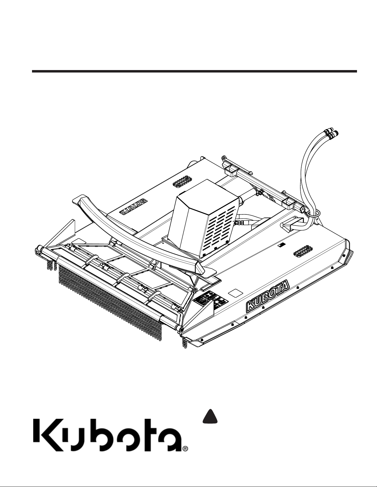
Table of Contents
Skid Cutter
AP-SC7072
70395
326-974MK
Operator’s Manual
Read the Operator’s Manual entirely. When you see this symbol,
the subsequent instructions and warnings are serious - follow
!
without exception. Your life and the lives of others depend on it!
Cover photo may show optional equipment not supplied
with standard unit.
For an Operator’s Manual and Decal Kit in French
Language, please see your Kubota dealer.
Printed 2/6/19
Page 2

Machine Identification
Record your machine details in the log below. If you replace this manual, be sure to transfer this information to
the new manual.
If you, or the dealer, have added Options not originally ordered with the machine, or removed Options that
were originally ordered, the weights and measurements are no longer accurate for your machine. Update the
record by adding the machine weight and measurements provided in the Specifications & Capacities Section
of this manual with the Option(s) weight and measurements.
Model Number
Serial Number
Machine Height
Machine Length
Machine Width
Machine Weight
Delivery Date
First Operation
Accessories
Dealer Contact Information
Name:
Street:
City/State:
Telephone:
Email:
!
WARNING: Cancer and reproductive harm - www.P65Warnings.ca.gov
California Proposition 65
2/6/19AP-SC7072 Skid Cutter 326-974MK
Page 3

Table of Contents
Table of Contents
Important Safety Information . . . . . . . . . . . . . 1
Safety at All Times . . . . . . . . . . . . . . . . . . . . . . . . . 1
Look for the Safety Alert Symbol . . . . . . . . . . . . . . . 1
Safety Labels . . . . . . . . . . . . . . . . . . . . . . . . . . . . . 4
Introduction . . . . . . . . . . . . . . . . . . . . . . . . . . . 6
Application . . . . . . . . . . . . . . . . . . . . . . . . . . . . . . . 6
Using This Manual . . . . . . . . . . . . . . . . . . . . . . . . . 6
Terminology . . . . . . . . . . . . . . . . . . . . . . . . . . . . . 6
Definitions . . . . . . . . . . . . . . . . . . . . . . . . . . . . . . 6
Owner Assistance . . . . . . . . . . . . . . . . . . . . . . . . . . 6
Serial Number . . . . . . . . . . . . . . . . . . . . . . . . . . . 6
Further Assistance . . . . . . . . . . . . . . . . . . . . . . . . 6
Section 1: Assembly & Set-up . . . . . . . . . . . . 7
Skid Steer Requirements . . . . . . . . . . . . . . . . . . . . 7
Dealer Preparations . . . . . . . . . . . . . . . . . . . . . . . . 7
Uncrating . . . . . . . . . . . . . . . . . . . . . . . . . . . . . . . . 7
Torque Requirements . . . . . . . . . . . . . . . . . . . . . . . 7
Hitch Hook-Up . . . . . . . . . . . . . . . . . . . . . . . . . . . . . 8
Height Adjustment Safety Chain . . . . . . . . . . . . . . . 9
Hydraulic Hose Hook-Up . . . . . . . . . . . . . . . . . . . . 10
Case Drain Assembly (Optional) . . . . . . . . . . . . . . 11
Pressure Gauge Assembly (Optional) . . . . . . . . . . 12
Section 2: Adjustments . . . . . . . . . . . . . . . . . 13
Equipment Clearances . . . . . . . . . . . . . . . . . . . . . 13
Section 3: Operating Procedures . . . . . . . . . 14
Operating Checklist . . . . . . . . . . . . . . . . . . . . . . . . 14
Safety Information . . . . . . . . . . . . . . . . . . . . . . . . . 14
Cutting Instructions . . . . . . . . . . . . . . . . . . . . . . . . 15
Transporting . . . . . . . . . . . . . . . . . . . . . . . . . . . . . 15
Skid Steer Shutdown Procedures . . . . . . . . . . . . . 16
General Operating Instructions . . . . . . . . . . . . . . . 16
Skid Steer Operating Instructions . . . . . . . . . . . 16
Skid Cutter Operating Instructions . . . . . . . . . . . 17
Section 4: Optional Equipment . . . . . . . . . . . 19
Pressure Gauge Bundle . . . . . . . . . . . . . . . . . . . . 19
Case Drain Bundle . . . . . . . . . . . . . . . . . . . . . . . . 19
Section 5: Maintenance & Lubrication . . . . . 20
Maintenance . . . . . . . . . . . . . . . . . . . . . . . . . . . . . 20
Hydraulic Maintenance . . . . . . . . . . . . . . . . . . . . . 20
Cutter Blade Maintenance . . . . . . . . . . . . . . . . . . . 20
Carbide Teeth Maintenance . . . . . . . . . . . . . . . . . 21
Skid Shoe Maintenance . . . . . . . . . . . . . . . . . . . . 22
Long-Term Storage . . . . . . . . . . . . . . . . . . . . . . . . 23
Lubrication Points . . . . . . . . . . . . . . . . . . . . . . . . . 24
Bi-Fold Door . . . . . . . . . . . . . . . . . . . . . . . . . . . . 24
In Line Bearing Housing . . . . . . . . . . . . . . . . . . . 24
Section 6: Specifications & Capacities . . . . . 25
Section 7: Features & Benefits . . . . . . . . . . . 27
Section 8: Troubleshooting . . . . . . . . . . . . . . 28
Section 9: Torque Values Chart . . . . . . . . . . . 29
Section 10: Legal Disclaimer & Warranty . . . 30
© Copyright 2019 All rights Reserved
Kubota provides this publication “as is” without warranty of any kind, either expressed or implied. While every precaution has been taken in the preparation of this manual, Kubota
assumes no responsibility for errors or omissions. Neither is any liability assumed for damages resulting from the use of the information contained herein. Kubota reserves the right
to revise and improve its products as it sees fit. This publication describes the state of this product at the time of its publication, and may not reflect the product in the future.
Kubota is a registered trademark.
All other brands and product names are trademarks or registered trademarks of their respective holders.
Printed in the United States of America.
2/6/19
Page 4

Table of Contents Continued
See previous page for Table of Contents.
Table of Contents
Parts Manual QR Locator
The QR (Quick Reference) code on the
cover and to the left will take you to the
Parts Manual for this equipment.
Download the appropriate App on your
smart phone, open the App, point your
phone on the QR code and take a picture.
Dealer QR Locator
The QR code on the left will
link you to available dealers
for Kubota products. Refer to
Parts Manual QR Locator on
this page for detailed
instructions.
2/6/19
Page 5
Important Safety Information
Important Safety Information
Listed below are common practices that may or may not be applicable to the products
described in this manual.
Safety at All Times
Careful operation is your best
assurance against an accident.
All operators, no matter how much
experience they may have, should
carefully read this manual and
other related manuals, or have the
manuals read to them, before
operating the power machine and
this attachment.
Thoroughly read and understand
the “Safety Label” section. Read
all instructions noted on them.
Do not operate the equipment
while under the influence of drugs
or alcohol as they impair the ability
to safely and properly operate the
equipment.
Operator should be familiar with all
functions of the skid steer and
attachment and be able to handle
emergencies quickly.
Make sure all guards and shields
appropriate for the operation are in
place and secured before
operating the attachment.
Keep all bystanders away from
equipment and work area.
Start skid steer from the driver’s
seat with steering levers and
hydraulic controls in neutral.
Operate skid steer and controls
from the driver’s seat only.
Never dismount from a moving
skid steer or leave skid steer
unattended with engine running.
Do not allow anyone to stand
between attachment and skid
steer while hooking-up.
Keep hands, feet, and clothing
away from power-driven parts.
While transporting and operating
equipment, watch out for objects
overhead and along side such as
fences, trees, buildings, wires, etc.
Store attachment in an area where
children normally do not play.
When needed, secure attachment
against falling with support blocks.
Look for the Safety Alert Symbol
The SAFETY ALERT SYMBOL indicates there is a
potential hazard to personal safety involved and extra
safety precaution must be taken. When you see this
!
Be Aware of
Signal Words
A signal word designates a degree or
level of hazard seriousness. The
signal words are:
!
DANGER
Indicates a hazardous situation that, if
not avoided, will result in death or
serious injury.
Safety Precautions for
Children
Tragedy can occur if the operator
is not alert to the presence of
children. Children generally are
attracted to attachments and their
work.
Never assume children will remain
where you last saw them.
Keep children out of the work area
and under the watchful eye of a
responsible adult.
Be alert and shut the attachment
and skid steer/track loader down if
children enter the work area.
Never carry children on the power
machine or attachment. There is
not a safe place for them to ride.
They may fall off and be run over
or interfere with the control of the
power machine.
Never allow children to operate the
power machine, even under adult
supervision.
Never allow children to play on the
power machine or attachment.
Use extra caution when backing
up. Before the power machine
starts to move, look down and
behind to make sure the area is
clear.
symbol, be alert and carefully read the message that
follows it. In addition to design and configuration of
equipment, hazard control, and accident prevention are
dependent upon the awareness, concern, prudence, and
proper training of personnel involved in the operation,
transport, maintenance, and storage of equipment.
!
WARNING
Indicates a hazardous situation that, if
not avoided, could result in death or
serious injury.
!
CAUTION
Indicates a hazardous situation that, if
not avoided, may result in minor or
moderate injury.
Skid Steer Shutdown
And Storage
Reduce engine speed and shut-off
all power to the attachment.
Park on solid, level ground and
lower attachment until it is flat on
the ground or support blocks.
Turn off engine, and remove
switch key to prevent unauthorized
starting.
Relieve all hydraulic pressures.
If included, raise seat bar and
move controls until both lock.
Wait for all components to stop
before leaving operator’s seat.
Use steps, grab-handles and
anti-slip surfaces when stepping
on and off the skid steer.
Detach and store attachment in an
area where children normally do
not play. Secure attachment by
using blocks and supports.
OFF
REMO
VE
2/6/19
1
Page 6
Important Safety Information
Listed below are common practices that may or may not be applicable to the products
described in this manual.
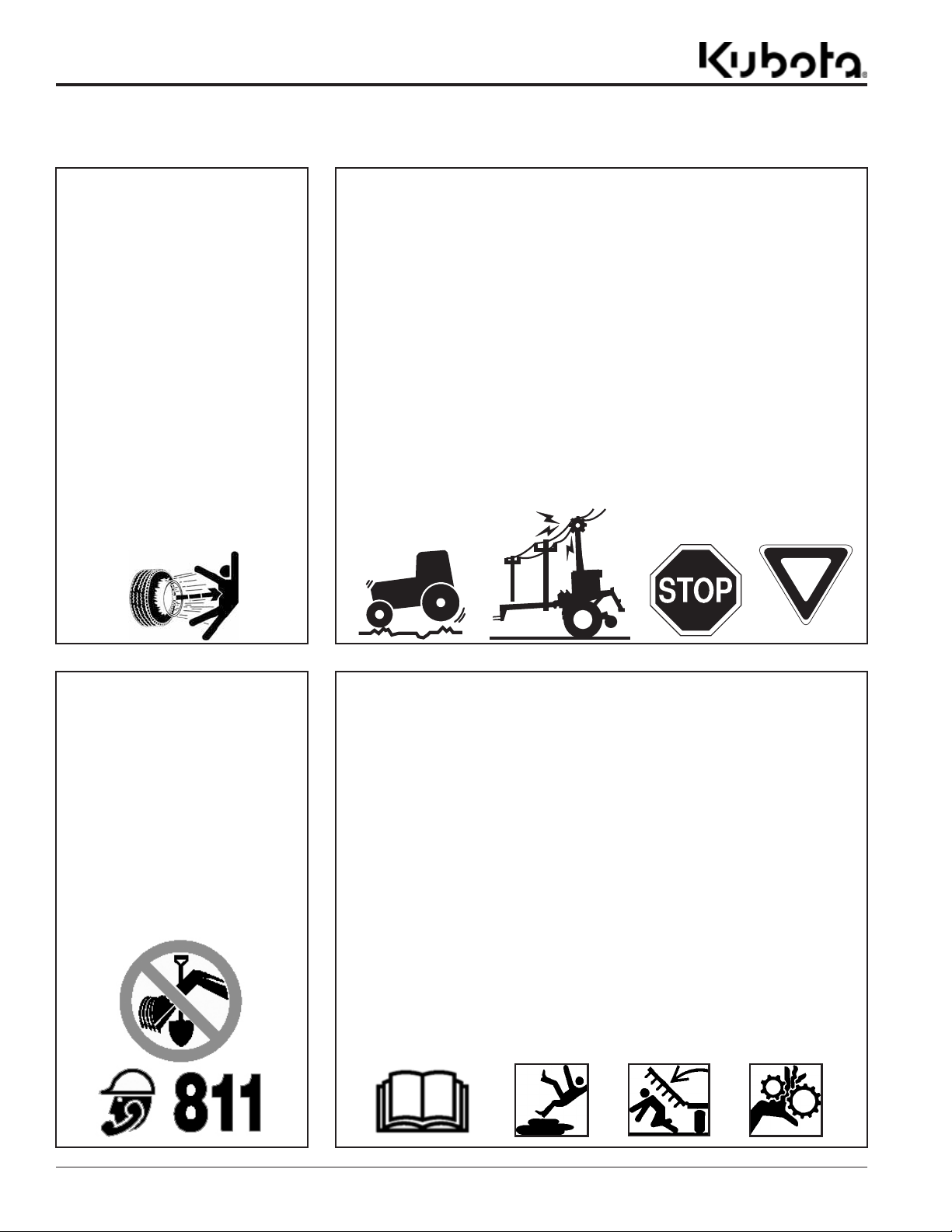
Tire Safety
Tire changing can be dangerous
and must be performed by
trained personnel using the
correct tools and equipment.
Always maintain correct tire
pressure. Do not inflate tires
above recommended pressures
shown in the Operator’s Manual.
When inflating tires, use a clip-on
chuck and extension hose long
enough to allow you to stand to
one side and NOT in front of or
over the tire assembly. Use a
safety cage if available.
Securely support the attachment
when changing a wheel.
When removing and installing
wheels, use wheel handling
equipment adequate for the
weight involved.
Make sure wheel bolts have been
tightened to the specified torque.
Transport Safely
Comply with federal, state, and local
laws.
Use towing vehicle and trailer of
adequate size and capacity. Secure
equipment towed on a trailer with
chocks, tie downs, and chains.
Sudden braking can cause a towed
trailer to swerve and upset. Reduce
speed if towed trailer is not equipped
with brakes.
Avoid contact with any overhead
utility lines or electrically charged
conductors.
Always drive with load on end of
loader arms low to the ground.
Always drive straight up and down
steep inclines with heavy end of skid
steer on the “uphill” side.
Engage park brake when stopped on
an incline.
Maximum transport speed for an
attached equipment is 20 mph. DO
NOT EXCEED. Never travel at a
speed which does not allow
adequate control of steering and
stopping. Some rough terrains
require a slower speed.
As a guideline, use the following
maximum speed weight ratios for
attached equipment:
20 mph when weight of attached
equipment is less than or equal to
the weight of machine towing the
equipment.
10 mph when weight of attached
equipment exceeds weight of
machine towing equipment but not
more than double the weight.
IMPORTANT: Do not tow a load that
is more than double the weight of the
vehicle towing the load.
Dig Safe - Avoid
Underground Utilities
USA: Call 811
CAN: digsafecanada.ca
Always contact your local utility
companies (electrical, telephone,
gas, water, sewer, and others)
before digging so that they may
mark the location of any
underground services in the
area.
Be sure to ask how close you can
work to the marks they
positioned.
Practice Safe Maintenance
Understand procedure before doing
work. Refer to the Operator’s Manual
for additional information.
Work on a level surface in a clean
dry area that is well-lit.
Lower attachment to the ground and
follow all shutdown procedures
before leaving the operator’s seat to
perform maintenance.
Do not work under any hydraulic
supported equipment. It can settle,
suddenly leak down, or be lowered
accidentally. If it is necessary to work
under the equipment, securely
support it with stands or suitable
blocking beforehand.
Use properly grounded electrical
outlets and tools.
Use correct tools and equipment for
the job that are in good condition.
Allow equipment to cool before
working on it.
Disconnect battery ground cable (-)
before servicing or adjusting
electrical systems or before welding
on equipment.
Inspect all parts. Make certain parts
are in good condition & installed
properly.
Replace parts on this attachment
with genuine Kubota parts only. Do
not alter this attachment in a way
which will adversely affect its
performance.
Do not grease or oil attachment
while it is in operation.
Remove buildup of grease, oil, or
debris.
Always make sure any material and
waste products from the repair and
maintenance of the attachment are
properly collected and disposed.
Remove all tools and unused parts
from the equipment before
operation.
2
2/6/19
Page 7
Important Safety Information
These are common practices that may or may not be applicable to the products described in
this manual.
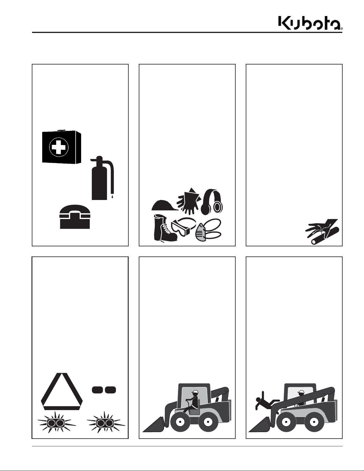
Prepare for Emergencies
Be prepared if a fire starts.
Keep a first aid kit and fire
extinguisher handy.
Keep emergency numbers for
doctor, ambulance, hospital, and
fire department near phone.
911
Wear Personal Protective
Equipment (PPE)
Wear protective clothing and
equipment appropriate for the job
such as safety shoes, safety
glasses, hard hat, and ear plugs.
Clothing should fit snug without
fringes and pull strings to avoid
entanglement with moving parts.
Prolonged exposure to loud noise
can cause hearing impairment or
hearing loss. Wear suitable
hearing protection such as
earmuffs or earplugs.
Operating equipment safely
requires the operator’s full
attention. Avoid wearing
headphones while operating
equipment.
Avoid High
Pressure Fluids Hazard
Escaping fluid under pressure
can penetrate the skin causing
serious injury.
Relieve all residual pressure
before disconnecting hydraulic
lines or performing work on the
hydraulic system.
Make sure all hydraulic fluid
connections are tight and all
hydraulic hoses and lines are in
good condition before applying
pressure to the system.
Use a piece of paper or
cardboard, NOT BODY PARTS,
to check for suspected leaks.
Wear protective gloves and
safety glasses or goggles when
working with hydraulic systems.
DO NOT DELAY. If an accident
occurs, see a doctor familiar with
this type of injury immediately.
Any fluid injected into the skin or
eyes must be treated
within a few hours or
gangrene may
result.
Use Safety
Lights and Devices
Slow moving tractors, skid steers,
and self-propelled machines can
create a hazard when driven on
public roads. They are difficult to
see, especially at night. Use the
Slow Moving Vehicle (SMV) sign
when on public roads.
Flashing warning lights and turn
signals are recommended
whenever driving on public roads.
Use Seat Belt and ROPS
Kubota recommends the use of a
CAB or roll-over-protectivestructures (ROPS) and seat belt
in almost all power machines.
Combination of a CAB or ROPS
and seat belt will reduce the risk
of serious injury or death if the
power machine should be upset.
If ROPS is in the locked-up
position, fasten seat belt snugly
and securely to help protect
against serious injury or death
from falling and machine
overturn.
Keep Riders Off
Machinery
Never carry riders on skid steer
or attachment.
Riders obstruct operator’s view
and interfere with the control of
the power machine.
Riders can be struck by objects
or thrown from the equipment.
Never use skid steer or
attachment to lift or transport
riders.
2/6/19
3
Page 8
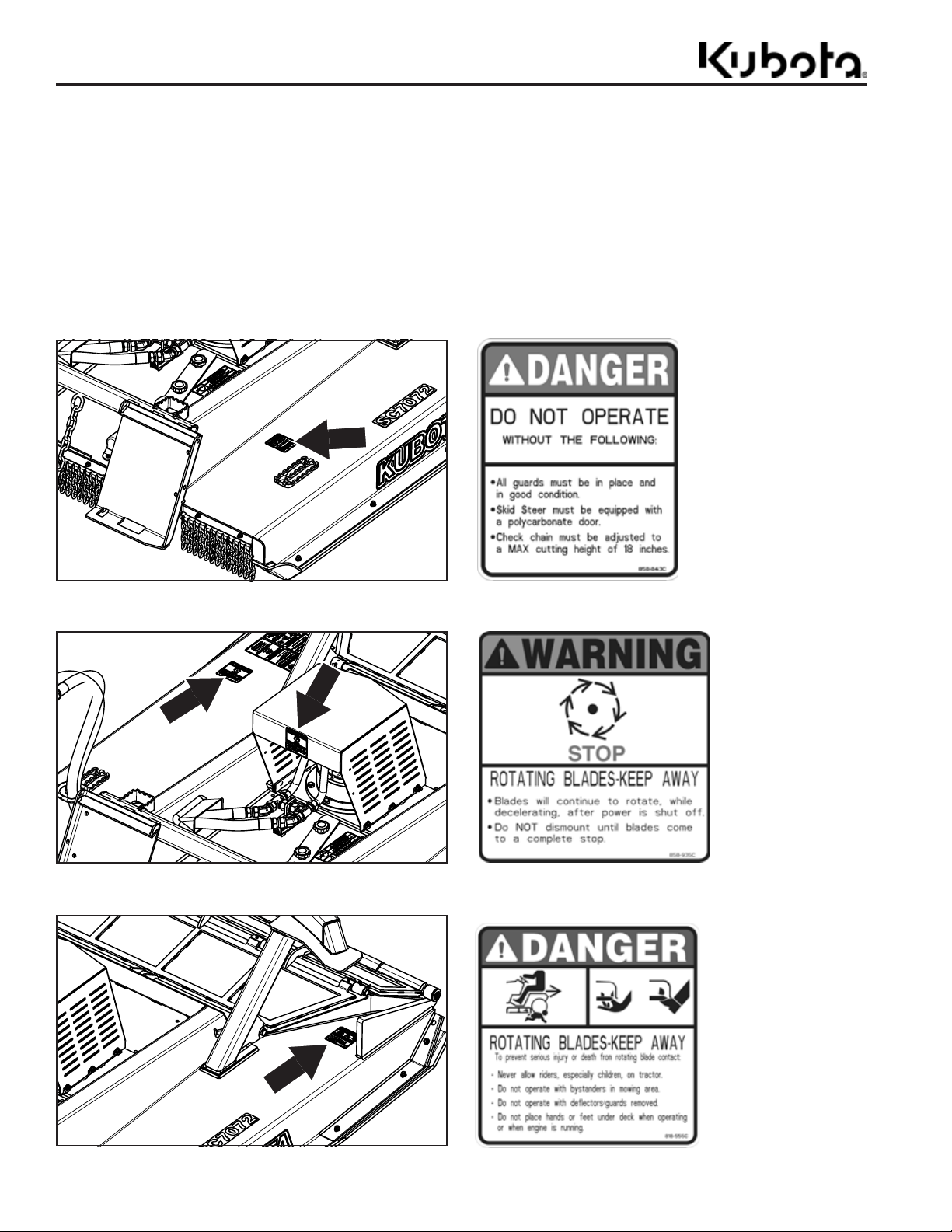
Table of Contents
Important Safety Information
Important Safety Information
Safety Labels
Your Skid Cutter comes equipped with all safety labels in place.
They are designed to help you safely operate your attachment.
Read and follow their directions.
1. Keep all safety labels clean and legible.
2. Refer to this section for proper label placement. Replace
all damaged or missing labels. Order new labels from your
nearest Kubota dealer. To find your nearest dealer, visit
our dealer locator at www.landpride.com.
3. Some new equipment installed during repair requires
safety labels to be affixed to the replaced component as
‘
specified by Kubota. When ordering new components make
sure the correct safety labels are included in the request.
4. Refer to this section for proper label placement.
To install new labels:
a. Clean surface area where label is to be placed.
b. Spray soapy water onto the cleaned area.
c. Peel backing from label and press label firmly onto the
surface.
d. Squeeze out air bubbles with edge of a credit card or
with a similar type of straight edge.
70398
70398
858-843C
Danger: Do Not Operate
858-935C
Warning:
Rotating Blades
818-555C
Danger:
70398
4
AP-SC7072 Skid Cutter 326-974MK 2/6/19
Rotating Blade Hazard
Page 9
Important Safety Information
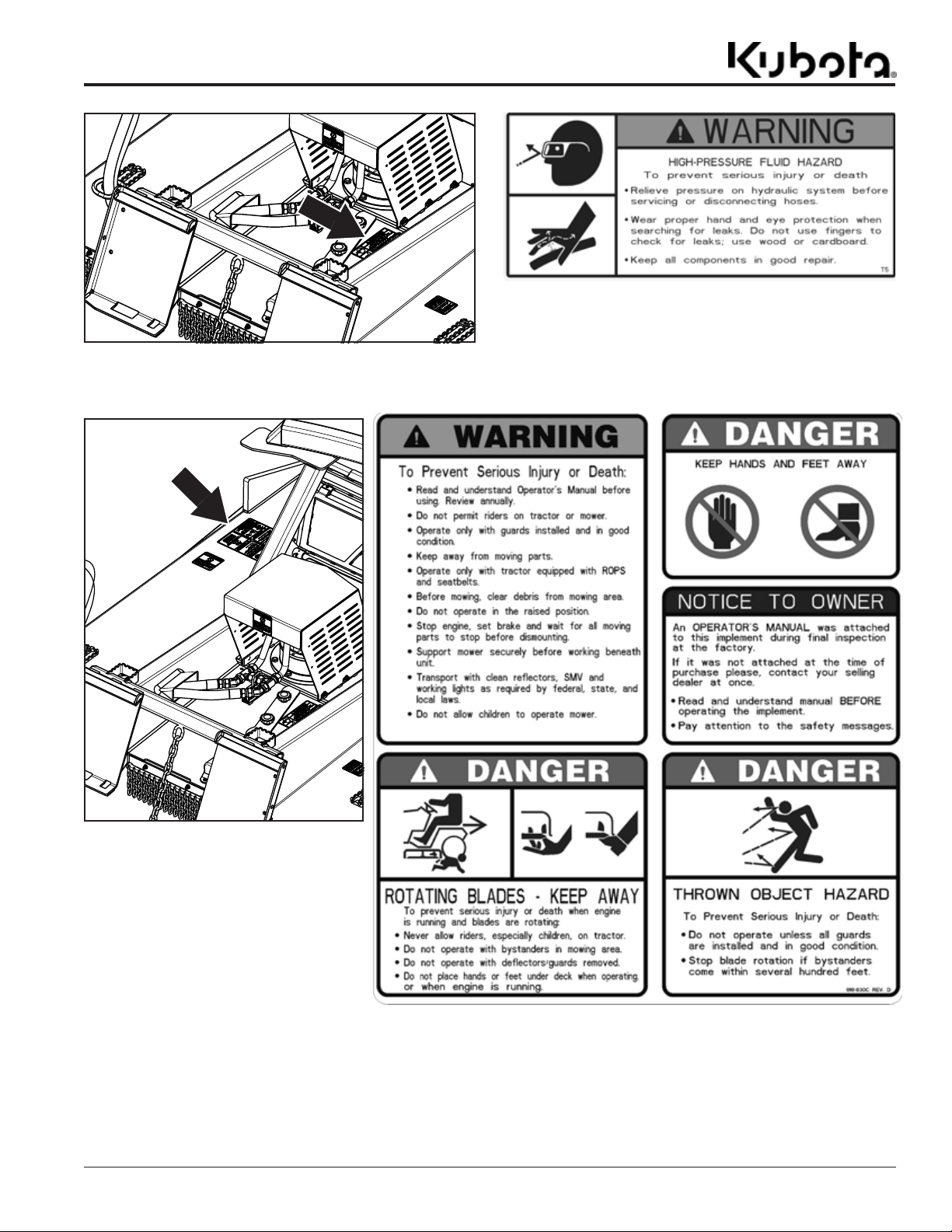
70398
70398
Table of Contents
818-831C
Warning: High Pressure
818-830C
Safety Combo
Danger: Keep Hands & Feet Away
Danger: Thrown Object Hazard
Danger: Rotating Blade Hazard
Warning: General Safety
Notice: Read Manual - Observe Safety Messages
AP-SC7072 Skid Cutter 326-974MK2/6/19
5
Page 10
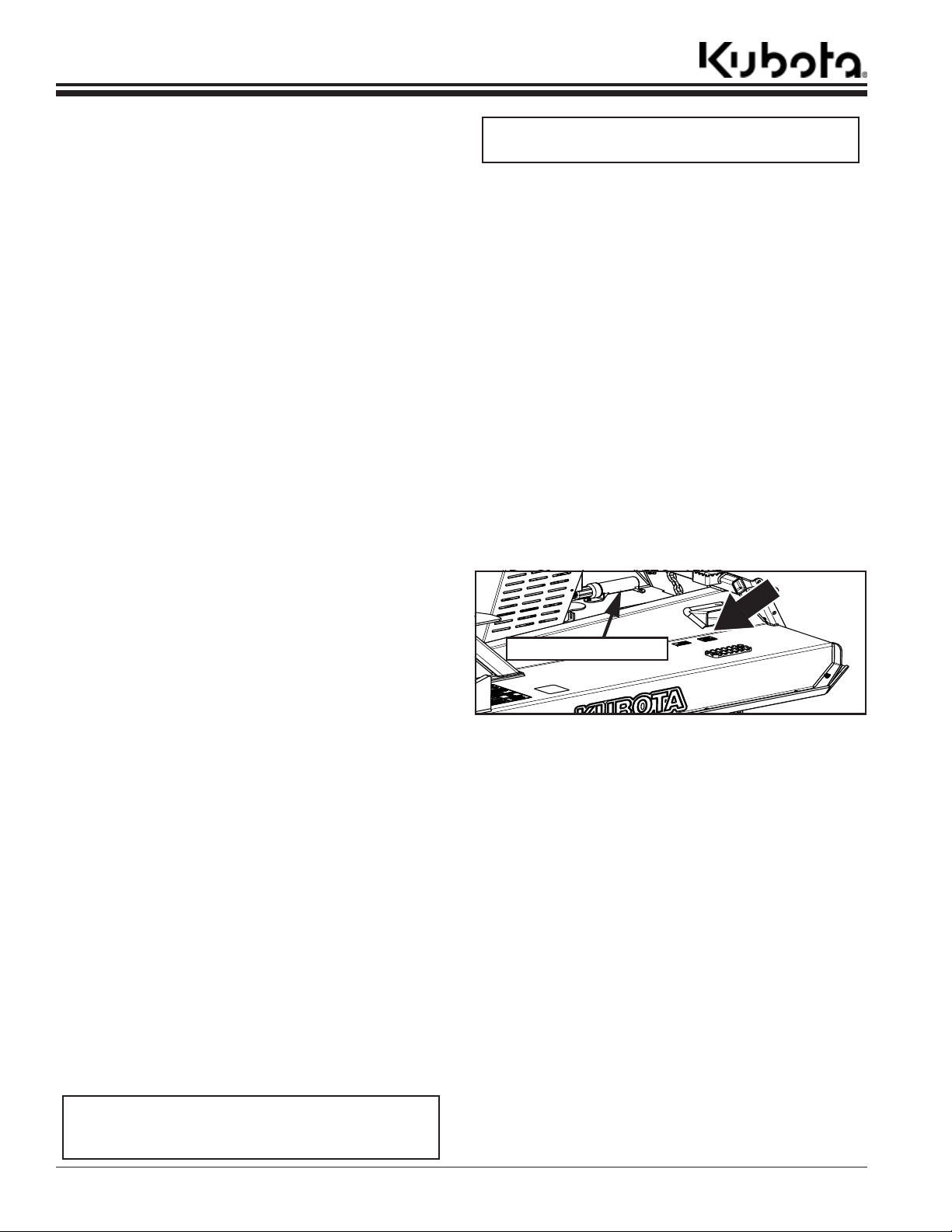
Table of Contents
Introduction
Introduction
Kubota welcomes you to the growing family of new
product owners. This Skid Cutter has been designed with
care and built by skilled workers using quality materials.
Proper assembly, maintenance, and safe operating
practices will help you get years of satisfactory use from
this product.
Application
SC7072 construction-grade Skid Cutter is designed with
the commercial or high use consumer in mind. It features
a rigid hitch mounting system, 1/4" thick deck, 4 swinging
blades, and a bi-fold door on the front. The SC7072 is
capable of cutting and shredding brush or trees up to 7" in
diameter. Carbide mulching teeth mounted on the bottom
of the blade carrier can be used for grinding stumps.The
strong push bars on top and under the door of the
SC7072 Skid Cutter allow the operator to push trees and
brush over and away from the operator as they are being
cut without damaging the unit. The ability to cut and
mulch trees and stumps level to the ground makes this
cutter ideal for clearing right-of-ways along road sides,
pipelines or under electrical transmission lines with the
speed and efficiency needed by today’s contractors.
Farmers, ranchers and land developers will also benefit
from this unit when clearing pastures or new
development areas. The SC7072 Skid Cutter utilizes the
power, compact size, and the go anywhere ability of a
SVL to access over grown areas where a tractor and
rotary cutter cannot go. The wide, full-length tapered skid
shoes prevent the cutter from digging in or getting hung
up in the soft ground usually found under heavy brush.
Use if this skid cutter is limited to standard brush cutting.
Use in significantly larger or denser brush will result in
excessive heat and may damage the skid cutter or the
skid steer.
Using This Manual
•
This Operator’s Manual is designed to help familiarize
you with safety, assembly, operation, adjustments,
troubleshooting, and maintenance. Read this manual
and follow the recommendations to help ensure safe
and efficient operation.
• The information contained within this manual was
current at the time of printing. Some parts may change
slightly to assure you of the best performance.
• To order a new Operator’s or Parts Manual, contact
your authorized dealer.
• Store your Operator’s Manual in the dry storage tube.
See Figure 1 on page 6 for location of storage tube.
Terminology
“Right” or “left” as used in this manual is determined by
facing the direction the machine will operate while in use
unless otherwise stated.
Definitions
IMPORTANT: A special point of information related
to the following topic. Kubota’s intention is this
information must be read & noted before continuing.
NOTE: A special point of information that the
operator should be aware of before continuing.
Owner Assistance
The dealer should complete the Online Warranty
Registration at the time of purchase. This information is
necessary to provide you with quality customer service.
The parts on your Skid Cutter have been specially
designed by Kubota/Land Pride and should only be
replaced with genuine Kubota parts. Contact a Kubota
dealer if customer service or repair parts are required.
Your Kubota dealer has trained personnel, repair parts,
and equipment needed to service the attachment.
See “Specifications & Capacities” on page 25 and
“Features & Benefits” on page 27 for additional
information and performance enhancing options.
Serial Number
For quick reference and prompt service, record model
and serial number on the inside cover page and again on
the warranty page. Always provide model number and
serial number when ordering parts and in all
correspondences with your Kubota dealer. For location of
your serial number plate, see Figure 1.
70402
Manual Storage Tube
Serial Number Plate Location
Figure 1
Further Assistance
Your Kubota dealer wants you to be satisfied with your
new attachment. If for any reason you do not understand
any part of this manual or are not satisfied with the
service received, the following actions are suggested:
1. Discuss any problems you have with your attachment
with your dealership service personnel so they can
address the problem.
2. If you are still not satisfied, seek out the owner or
general manager of the dealership, explain the
problem, and request assistance.
3. For further assistance write to:
Kubota by Land Pride
Service Department
1525 East North Street
P.O. Box 5060
Salina, Ks. 67402-5060
E-mail address
lpservicedept@landpride.com
6
AP-SC7072 Skid Cutter 326-974MK 2/6/19
Page 11
Table of Contents
Section 1: Assembly & Set-up
Section 1: Assembly & Set-up
Skid Steer Requirements
The Skid Cutter is designed to attach to skid steer loaders
and track loaders with the following minimum
requirements:
Hitch type . . . . . . . . . . . . . . . . . . . . . . . . . ISO 24410
Rated Operating Load . . . . . . . . . . . . . . . . . 3500 lbs
Hydraulic Pressure Rating . . . . . . . . . . up to 3500 psi
High Volume Motor & Hoses . . . . . . . . . . . 26-43 gpm
Door. . . . . . . . . . . . . . . . . . . . . . . . . . . Polycarbonate
Case Drain . . . . . . . . . . . . . . . . . . . . . . . . . .Optional
Skid Steer Weight. . . . . . . . . . . . . See warning below
!
WARNING
To avoid serious injury or death:
• Lightweight power machines may need weight added to the
rear to maintain steering control and prevent forward
tipping or side tipping caused by a heavy front load. Consult
your power machine Operator’s Manual to determine
proper weight requirements and maximum weight
limitations.
• Consult your skid steer’s manual for operating capacity,
lifting capacity, and operating specifications. Exceeding
rated capacities and specifications can result in a roll-over
or other serious hazard.
• Do not operate any hammer or mulching equipment on an
open cab machine or on a machine with a tempered front
glass window/door. We strongly recommend use of a
polycarbonate front glass door/window when operating any
hammer or mulching equipment.
Dealer Preparations
!
WARNING
To avoid serious injury or death:
Allow only persons to operate this attachment who have fully
read and comprehended this manual, who are properly trained
to operate the attachment safely, and who are age 16 or older.
Serious injury or death can result from the failure to read,
understand, and follow instructions provided in this manual.
Read and understand the Operator’s Manual for this
cutter. An understanding of how it works will aid in the
assembly and setup of your cutter.
This Skid Cutter has been partially assembled at the
factory. However, some assembly will be necessary.
It is best to go through the “Assembly Checklist” on this
page before assembling the cutter. Speed up your
assembly task and make the job safer by having all the
needed parts and equipment readily at hand.
Ensure that the intended skid steer conforms to the
requirements stated under the heading “Skid Steer
Requirements” on this page.
Uncrating
!
WARNING
To avoid serious injury or death:
Always secure cutter with an overhead crane, fork lift, or
other suitable lifting device before removing hardware bags,
shipping components, bands, lag screws, or hitch pins. The
cutter can suddenly fall.
1. Secure deck with an overhead crane, fork lift, or other
suitable means before cutting shipping support
bands and unbolting cutter from shipping crate.
2. Cut bands securing parts bags to the shipping crate.
3. Remove bolts securing hitch to the shipping crate.
4. Cut center band securing hitch to shipping crate.
5. Carefully lift cutter from crate and lower onto its skids
or onto support stands capable of supporting the
cutter.
6. Remove remaining components from crate. Discard
crate.
Torque Requirements
See “Torque Values Chart” on page 29 to determine
correct torque values when tightening hardware.
Assembly Checklist
All hardware from the factory has been installed. If a part or
fastener is temporarily removed for assembly, remember where
it goes. Keep parts separated.
Be sure the parts get used in the correct location. By double
checking while you assemble, you will lessen the chance of
using a bolt incorrectly that may be needed later. Use Parts
Manual to identify location of parts you are unsure of where
they are used.
All grease fittings are in place and lubricated.
Miscellaneous assembly tools: hammer, tape measure,
assortment of wrenches and a level.
Have fork lift or loader along with chains and safety stands
sized for the job ready for the assembly task.
Auxiliary weights (depending on skid steer
Have a minimum of 2 people at hand while assembling.
Safety decals are legible and undamaged.
Loose parts bag/box shipped with the Skid Cutter.
Check
size).
AP-SC7072 Skid Cutter 326-974MK2/6/19
7
Page 12

Section 1: Assembly & Set-up
Table of Contents
Zip tie hydraulic hoses together.
Hose ring
Height Adjustment Safety Chain (Chain must run under the upper
70405
cross tube and skid steer hitch plate then attach to Skid Steer’s
lower hitch loop). See Figure 1-2.
Skid Steer Hook-Up
Figure 1-1
Hitch Hook-Up
Refer to Figure 1-1:
!
DANGER
To avoid serious injury or death:
A crushing hazard exists while hooking-up and unhooking the
attachment. Do not allow anyone to stand between attachment
and power machine while approaching or backing away from
the attachment. Do not operate lift and/or tilt controls while
someone is near the power machine and/or attachment.
1. Make sure hydraulic hoses and height adjustment
safety chain do not interfere with hitch hook-up.
2. Drive skid steer slowly to the Skid Cutter making sure
the front hitch plate of the skid steer is parallel with
the Skid Cutter hitch.
3. Tilt top of skid steer hitch plate slightly forward.
4. Place top of skid steer hitch plate directly under the
Skid Cutter top angle bar.
5. Slowly lift skid steer hitch until it fully contacts the
Skid Cutter top angle bar.
6. Slowly rotate skid steer hitch plate back.
7. Engage skid steer lock handles. Make sure the pins
go through the bottom slots of the Skid Cutter’s hitch
and the handles lock down.
NOTE: If the skid steer is not equipped with
hydraulic lock handles, the skid steer must be shut
down and lock handles must be manually engaged.
Refer to “Skid Steer Shutdown Procedures” on
page 16.
Female Coupler
Male Coupler
Top Angle Bar
Blade Bolt Access Hole
Upper Cross Tube
Bottom Slots
Refer to Figure 1-2
8. Connect the safety chain to the skid steer. For
additional information on how to adjust the safety
chain, see “Height Adjustment Safety Chain” on
page 9.
Safety chain stud
Upper cross tube
70031
Height Adjustment Safety Chain (Kubota SVL Shown)
Skid steer hitch plate
Figure 1-2
IMPORTANT: The safety chain must run under the
upper cross tube and the skid steer hitch plate or
damage can occur.
8
AP-SC7072 Skid Cutter 326-974MK 2/6/19
Page 13

Section 1: Assembly & Set-up
70033
Table of Contents
Height Adjustment Safety Chain
Bottom of Rear
Skid Shoes
Nominal Cutting Height (SVL shown)
16.5"
Ground Level
Figure 1-3
Height Adjustment Safety Chain
!
To avoid serious injury or death:
DANGER
• Do not operate cutter with skid shoes higher than 16 1/2"
off the ground. Always use height adjusting safety chain to
limit cutting height. Raising cutter too high will throw
debris at the operator.
• Always secure equipment with solid, non-concrete supports
before working under it. Never go under equipment
supported by concrete blocks or hydraulics. Concrete can
break, hydraulic lines can burst, and/or hydraulic controls
can be actuated even when power to hydraulics is off.
Refer to Figure 1-3:
For safety, the cutter’s rear skid shoes should not be
raised higher than 16 1/2" off the ground (18" maximum
cutting height).
NOTE: Two people may be required to install and
adjust the height adjustment safety chain.
1. Raise cutter’s rear skid shoes slightly less than
16 1/2" off the ground. Secure the cutter with solid
(non-concrete) support blocks.
2. Shut skid steer down properly. See “Skid Steer
Shutdown Procedures” on page 16.
3. Run height adjustment safety chain under the
skid steer hitch plate to the skid steer lower hitch
loop. Thread chain through the hitch loop and back
toward the hitch plate. Connect quick link coupler to a
chain loop as shown in Figure 1-4.
Lower Hitch Loop
NOTE: When attaching the Skid Cutter to a Kubota
SVL machine, height adjustment safety chain (#2)
should be looped around SVL
tie-down bar (#1) and adjusted so that the cutter
cannot be raised over 16.5" off the ground as shown
in Figure 1-4 below.
1
2
16.5"
SC70 Height Adjustment (SVL Shown)
Figure 1-4
4. Raise cutter up until the safety chain is tight. Check
height of rear skid shoes.
5. If rear skid shoes are more than 16 1/2" above
ground level, lower cutter and make necessary
adjustments to the safety chain to limit rear skid shoe
height to 16 1/2" maximum.
6. Tighten quick link coupler nut to secure safety chain.
70032
AP-SC7072 Skid Cutter 326-974MK2/6/19
9
Page 14

Section 1: Assembly & Set-up
Table of Contents
Hydraulic Hose Hook-Up
Refer to Figure 1-1 on page 8:
!
WARNING
To avoid serious injury or death:
• Shut power machine down and release all hydraulic
pressure to the equipment before connecting or
disconnecting hydraulic hoses to or from the power
machine.
• Hydraulic fluid under high pressure can penetrate the skin
and/or eyes causing a serious injury. Wear protective gloves
and safety glasses or goggles when working with hydraulic
systems. Use a piece of cardboard or wood rather than
hands when searching for leaks. A doctor familiar with this
type of injury must treat the injury within a few hours or
gangrene may result. DO NOT DELAY.
.
IMPORTANT: The customer must select best way to
route the hydraulic hoses. Make sure the hoses will
not contact the skid steer wheels or tracks. See
“Equipment Clearances” on page 13
for detailed instructions on how to check for
clearances.
Refer to Figure 1-5:
1. If attaching to a Kubota SVL machine, be sure to
route hydraulic hoses through hose loop (#1) on the
left side of the cutter hitch as shown.
3. Connect male and female couplers on the cutter to
the appropriate skid steer flat faced couplers.
4. Operate skid steer to check blade rotation. The SC70
is designed to have cutter blades rotate clockwise
when looking down at the deck.
5. Zip tie hydraulic hoses together every 2 feet from
male and female couplers.
NOTE: Use of Kubota’s SVL Hose Stay is not
recommended for this attachment.
Do Not Use
SVL Hose Stay
1
70030
Hose Route For Kubota SVL Machine
Figure 1-5
Refer to Figure 1-1 on page 8:
2. Thread hoses through any hose holders that may be
helpful on the machine operating the cutter. See your
skid steer Operator’s Manual for instruction on how to
use these hose holders.
10
AP-SC7072 Skid Cutter 326-974MK 2/6/19
Page 15

Section 1: Assembly & Set-up
Table of Contents
70406
Case Drain Assembly
Figure 1-6
Case Drain Assembly (Optional)
Refer to Figure 1-6:
1. Ensure the Cutter is parked on a flat level surface,
and if the cutter is attached to a skid steer, follow
proper shut down procedures. See “Skid Steer
Shutdown Procedures” on page 16.
2. Loosen six 3/8"-16 hex nuts (#2). Removing the hex
nuts is not necessary.
3. Remove the motor shroud (#1) by pushing it toward
the front of the unit then lifting it upward.
4. Remove plug from port (C) in hydraulic motor (#4).
5. Attach adapter fitting (#3) to port (C) in hydraulic
motor (#4) as shown and tighten to correct torque.
6. Route hydraulic hose (#5) through designated areas
(A & B) as shown.
7. Attach female end of hydraulic hose (#5) to adapter
fitting (#3) and tighten.
8. Place the motor shroud back in its designated place
and pull back to lock it in place. Tighten hex nuts (#2)
to correct torque.
9. Attach flat faced coupler (#6) to the male end of
hydraulic hose (#5) and tighten.
10. Connect coupler (#6) to case drain reservoir on skid
steer.
11. Zip tie the case drain hydraulic hose to the two
existing hoses.Pressure Gauge Assembly (Optional)
!
WARNING
To avoid serious injury or death:
Cutter deck can be slippery when wet. Always step on grip
pads when possible. Never hurry. Make sure you have secure
footing and hand hold when walking on the deck.
AP-SC7072 Skid Cutter 326-974MK2/6/19
11
Page 16

Section 1: Assembly & Set-up
Table of Contents
Pressure Gauge Assembly
Figure 1-7
Pressure Gauge Assembly (Optional)
Refer to Figure 1-7:
1. Ensure the Cutter is parked on a flat level surface, and
if the cutter is attached to a skid steer, follow proper
shut down procedures. See “Skid Steer Shutdown
Procedures” on page 16.
2. Loosen six 3/8"-16 hex nuts (#2). Removing the hex
nuts is not necessary.
3. Remove the motor shroud (#1) by pushing it toward
the front of the unit then lifting it upward.
4. Remove 3/4" cap (#10) from adapter fitting (#9).
5. Attach the 3/4" end of hydraulic hose (#8) to adapter
fitting (#9) and tighten.
6. Attach the pressure gauge (#3) to the pressure gauge
mount (#11) using three 8-32 X 3/4" round head
screws (#4). Put the screws through the holes in the
pressure gauge and pressure gauge mount and fasten
them with three flat washers (#5), lock washers (#6)
and 8-32 hex nuts (#7). Tighten the hex nuts to correct
torque.
7. Attach the 3/8" end of hydraulic hose (#8) to the
pressure gauge (#3) and tighten.
70407
8. Place the motor shroud (#1) back in its designated
place and pull back to lock it in place. Tighten hex
nuts (#2) to correct torque.
9. Attach the pressure gauge mount (#11) to the motor
shroud (#1) using two 1/4-20 X 3/4" hex head bolts
(#14). Fasten with 1/4" flat washers (#13) and 1/4-20
hex nuts (#12). Tighten to correct torque.
!
WARNING
To avoid serious injury or death:
Cutter deck can be slippery when wet. Always step on grip pads
when possible. Never hurry. Make sure you have secure footing
and hand hold when walking on the deck.
12
AP-SC7072 Skid Cutter 326-974MK 2/6/19
Page 17

Table of Contents
Section 2: Adjustments
Section 2: Adjustments
Equipment Clearances
Visually inspect hydraulic hoses for possible pinch points
and length. Make any necessary adjustments before
putting equipment into service.
1. If necessary, have someone stand nearby that can
motion for the operator to stop if a problem develops
while checking for clearances.
2. With deck lowered to its minimum cutting height,
slowly tilt the hitch plate back raising the front of the
cutter while watching for interferences between the
skid steer and cutter. Make sure hydraulic hoses are
long enough and do not become pinched through the
full range of motion.
3. With hydraulic cylinders still retracted, slowly raise
loader arms up while continuing to watch for
interferences between the skid steer and cutter until
height adjustment safety chain limit is reached.
4. Slowly tilt the hitch plate forward until the front of the
deck is touching the ground.
5. Tilt hitch plate back until the deck looks parallel with
the ground.
6. Slowly lower deck down while retracting hydraulic
cylinders on end of loader arms until deck is level and
resting on the ground.
7. Be sure to make any necessary corrections to the
hydraulic hoses before putting cutter into service.
AP-SC7072 Skid Cutter 326-974MK2/6/19
13
Page 18

Table of Contents
Section 3: Operating Procedures
Section 3: Operating Procedures
Operating Checklist
Hazard control and accident prevention are dependent
upon the awareness, concern, prudence, and proper
training involved in the operation, transport, storage and
maintenance of the Skid Cutter. Therefore, it is absolutely
essential that no one operates the Skid Cutter unless
they are age 16 or older and have read, fully understood,
and are totally familiar with the Operator’s Manual. Make
sure the operator has paid particular attention to:
• Important Safety Information, page 1
• Section 1: Assembly & Set-up, page 7
• Section 2: Adjustments, page 13
• Section 3: Operating Procedures, page 14
• Section 5: Maintenance & Lubrication, page 20
Perform the following inspections before using your
Skid Cutter.
Operating Checklist
Make sure guards and shields are in place and
secure. Make sure polycarbonate door is in
good working order.
Inspect hydraulic hoses and replace if they are
worn, damaged, or leak.
Replace with genuine
Grease all fittings. Refer to “Lubrication
Points”.
Check Skid Cutter initially and periodically for
loose bolts & nuts.
See “Torque Values Chart”.
Check Ref.
Page 1
Page 3
OEM parts.
Page 24
Page 29
Safety Information
!
DANGER
To avoid serious injury or death:
• Rotary Cutters have the ability to discharge objects at high
speeds; therefore, the use of front and rear safety guards is
mandatory when cutting along roadways and in areas where
people may be present. Stop blade rotation if a bystander is
in or around the area.
• Do not use cutter as a fan. Cutting blades are not properly
designed or guarded for this use.
• Do not operate cutter with skid shoes higher than 16 1/2"
off the ground. Always use height adjusting safety chain to
limit cutting height. Raising cutter too high will throw
debris at the operator.
• All guards and shields must be installed and in good
working condition while operating the attachment.
• Do not operate cutter after dark without working lights.
The equipment can hit unseen objects or be hit by other
vehicles. The operator can loose control of the power unit
and cutter causing a wreck or roll-over.
!
WARNING
To avoid serious injury or death:
• Hydraulic fluid under high pressure can penetrate the skin
and/or eyes causing a serious injury. Wear protective gloves
and safety glasses or goggles when working with hydraulic
systems. Use a piece of cardboard or wood rather than
hands when searching for leaks. A doctor familiar with this
type of injury must treat the injury within a few hours or
gangrene may result. DO NOT DELAY.
• Never carry riders on the attachment or power machine.
Riders can obstruct the operator’s view, interfere with
control of the equipment, be pinched by moving
components, become entangled in rotating components, be
struck by objects, be thrown or fall from the equipment, etc.
• Do not cut on steep inclines. The power machine could flip
over causing damage to the equipment and serious bodily
injury or death.
• Do not operate any hammer or mulching equipment on an
open cab machine or on a machine with a tempered front
glass window/door. We strongly recommend use of a
polycarbonate front glass door/window when operating any
hammer or mulching equipment.
• Allow only persons to operate this implement who have
fully read and comprehended this manual, who have been
properly trained in the safe operation of this implement, and
who are age 16 or older. Serious injury or death can result
from the inability to read, understand, and follow
instructions provided in this manual.
• Do not become entangled in hydraulic hoses while entering
or exiting the skid steer operator station.
• Do not operate cutter without a polycarbonate door
mounted to the cab and protective eye wear such as safety
glasses or goggles. Flying objects from the cutter can cause
serious injury to the body and eyes.
• Do not abuse equipment. Incorrect use of the attachment
can damage equipment structurally and cause serious
injury or death..
• Do not travel too fast. The rougher the terrain, the slower
you must travel. Always travel at a speed slow enough to be
able to adjust the deck height before running it into the
ground. Also, travel slow enough to stop before running or
turning into obstacles ahead and on either side.
• Do not use attachment to lift, carry, push or tow other
equipment and objects. It is not properly designed or
guarded for this use. The operator could lose control and
cause a tipping hazard.
• Do not use attachment to pull and/or pry fence posts,
stumps, roots, rocks, or other objects out of the ground. It is
not properly designed or guarded for this use.
• Do not use attachment as a lifting device for people or as a
work platform. It is not properly designed or guarded for
this use.
14
AP-SC7072 Skid Cutter 326-974MK 2/6/19
Page 19

Section 3: Operating Procedures
Table of Contents
• Do not operate cutter with blades that are out-of-balance,
bent, excessively worn, excessively nicked, or with blade
bolts that are excessively worn. Such blades can break loose
at high speeds.
• Do not alter attachment or replace parts on the attachment
with other brands. Other brands may not fit properly or
meet OEM specifications. They can weaken the integrity
and impair the safety, function, performance, and life of the
attachment. Replace parts only with genuine OEM parts.
• Do not exceed rated cutting capacity of your cutter. See
specifications & capacities for specified cutting capacity.
Exceeding rated cutting capacity can damage drive
components, cutter blades, and deck components.
• Cutter deck can be slippery especially when wet. Always
step on anti-slip surfaces when possible. Never hurry. Make
sure you have secure footing and hand hold when walking
on the deck.
• Buildup of debris around moving components and
gearboxes is a fire hazard. Keep rotating parts and
gearboxes free from debris to avoid serious injury and
property damage.
• Avoid catching hydraulic hoses on brush, posts, tree limbs,
and other protrusions that could damage and/or break them.
• Always shut skid steer down using “Skid Steer Shut Down
Procedure” provided in this manual before dismounting to
maintain and/or make adjustments to the skid steer cutter.
Cutting Instructions
IMPORTANT: Do not over angle hitch plate forward.
Over angling can cause damage to deck and hitch.
The Skid Cutter should be operated in one of three ways.
a. If cutting grass, weeds, or light brush operate with
the deck rear slightly higher than deck front.
b. If cutting heavy brush, operate with the deck front
3" to 5" higher that the deck rear for the length of
the cutter. Lower the deck front and backup slowly
mulching the debris and leveling brush root spike
to ground level.
c. If cutting and mulching trees, operate by raising
deck front 12" to 15" higher than deck rear. Cut the
tree so that it falls away from the operator. Upon
tree falling, back up, then lower the deck front 6",
drive forward to remove stump, back up, lower
deck front to the ground, drive forward to mulch
the stump to ground level. Lift deck front 12" to 15"
and repeat steps above to mulch the fallen tree.
IMPORTANT: Do not lower operating mulcher down
onto trees, saplings or bushes that are 12" tall.
NOTE: Your cutter is equipped with free swinging
cutting blades to reduce shock loads to the cutter
when striking an obstacle.
1. Thoroughly inspect the area to be cut for debris and
unforeseen objects. Mark any potential hazards.
2. Set skid steer hydraulic lift arms and hitch angle to
position the deck front at the preferred cutting height
and the deck rear slightly higher.
3. Start the skid steer and engage hydraulic motor.
Allow several seconds for cutter blades to become
aligned properly. If deck continues to vibrate after
several seconds, stop motor and inspect blades.
4. It is important to maintain correct hydraulic motor
speed. Loss of motor speed will allow the blades to
hinge back and result in ragged, uneven cutting.
5. Ground speed depends on two things: the density of
material being cut and size of skid steer. Never run
fast enough to overload the skid steer or cutter.
6. This cutter was designed to cut brush and small trees
on gently sloping or slightly contoured right-of-ways,
pastures, set aside acres, and row crop fields.
25616
DO NOT OPERATE WITH FRONT OF
SKID STEER OFF THE GROUND
Figure 3-1
IMPORTANT: Do not operate cutter or navigate
turns with front of the skid steer off the ground.
Operating in above fashion will cause damage to
deck & hitch. Refer to Figure 3-1.
Transporting
!
WARNING
To avoid serious injury or death:
When traveling on roadways, travel in such a way that other
vehicles may pass you safely. Use LED lights, clean reflectors,
and a slow moving vehicle sign that is visible from the back to
warn operators in other vehicles of your presence. Always
comply with all federal, state, and local laws.
1. Be sure to reduce ground speed when turning; and,
leave enough clearance so the Skid Cutter does not
contact obstacles such as buildings, trees, or fences.
2. Select a safe ground travel speed when transporting
from one area to another. When traveling on
roadways, transport in such a way that faster moving
vehicles may pass you safely.
3. Decrease transport speed when traveling over rough
or hilly terrain.
AP-SC7072 Skid Cutter 326-974MK2/6/19
15
Page 20

Section 3: Operating Procedures
Table of Contents
4. When transporting skid steer and Skid Cutter on a
trailer:
• Use towing vehicle and trailer of adequate
capacity.
• Always drive up a ramp with heavy end uphill.
• Engage skid steer park brake and remove ignition
switch key once it is loaded.
• Secure skid steer loader and attachment using tie-
downs and chains.
Skid Steer Shutdown Procedures
The following are basic skid steer shutdown procedures.
Follow these procedures and any additional shutdown
procedures provided in your skid steer Operator’s
Manual before leaving the operator’s seat.
1. Reduce engine speed and shut-off all power to the
attachment.
2. Park on solid, level ground and lower attachment until
it is flat on the ground or on solid (non-concrete)
support blocks.
3. Turn off engine, and remove switch key to prevent
unauthorized starting.
4. Relieve all hydraulic pressure to auxiliary hydraulic
lines.
5. If included, raise seat bar and move controls until
both lock.
6. Wait for all components to come to a complete stop
before leaving the operator’s seat.
7. Use steps, grab-handles and anti-slip surfaces when
stepping on and off the skid steer or attachment.
General Operating Instructions
It is absolutely essential that you read and understand
both the Operator’s Manual for your Kubota Skid Cutter
and the Operator’s Manual for the skid steer unit you
intend to attach it to before attempting to operate or cut
with this combination of equipment. You must be able to
read, comprehend, and adhere to all safety warnings and
decals in order to avoid personal injury, fatalities, injury to
others, or costly damage to property and equipment. We
highly recommend that you be a skilled and competent
skid steer operator prior to attaching and attempting to
use the Skid Cutter. If there is any part of the information
above or safe operating procedures you do not
understand, please contact your nearest authorized
dealer for a full explanation and training session if
necessary.
If attachment is to be operated in reverse, make sure
visibility to the rear of the power unit is appropriate for the
attachment. Backup camera or mirror is recommended.
Maintain cleanliness of lens or mirror.
Skid Steer Operating Instructions
!
WARNING
To avoid serious injury or death:
Do not operate any hammer or mulching equipment on an
open cab machine or on a machine with a tempered front
glass window/door. We strongly recommend use of a
polycarbonate front glass door/window when operating any
hammer or mulching equipment.
Assuming you have met all of the requirements and
taken them seriously, it is time to take the next step and
that is accomplished by dressing appropriately for the
task. You will need to put on protective eye wear such as
safety glasses, goggles, or a face shield. A hard hat,
steel toed safety shoes, gloves, and hearing protection
are also highly recommended. Never wear loose fitting
clothing. A respirator or filter mask will help reduce the
amount of dust, pollen, or agricultural chemicals
potentially inhaled by the operator.
The next step is a static or non-running pre-inspection of
the skid steer unit. You will want to make sure that the
skid steer is equipped with a fully functioning ROPS (Roll
Over Protective Structure) which does include seat belts
and an operator safety enclosure. The cab must also be
equipped with a polycarbonate door, which may have
been supplied with the skid steer unit. If the skid steer is
to be operated on local roadways, it must be equipped
with appropriate Slow Moving Vehicle (SMV) and other
required lighting packages so as to make it compliant
with federal, state and local department of transportation
requirements. The cutter drive motor must be matched to
the output of the hydraulic capacity of the skid steer.
Failure to do this could result in serious over-speeding of
the cutting unit possibly resulting in serious injury,
fatalities, or property damage. The universal quick-hitch
mount should be in good working order and latches
should be located to the open position. There should be
no evidence of hydraulic leaks in and around the
auxiliary hydraulic couplers. There must be a readily
accessible attaching point for the Skid Cutter lift-limit
chain on the lower front portion of the chassis frame.
Finally make sure that all shields and safety features are
in place and fully functional.
The next step is to perform a running check of the skid
steer unit. As you get onto the skid steer and into the
operator’ compartment always use factory provided
hand-holds to ease or stabilize your entry. Fasten your
seat belt once you are seated and begin to mentally
orient yourself with the position of all controls, switches,
pedals, levers, and their related functions. Once you are
sure that the park brake is on, no people or animals are
in close proximity, all control levers, pedals, and
hydraulic systems are in neutral position, go ahead and
start the engine. With the engine now running and the
throttle at approximately one third, test all controls to
make sure they are fully functioning. If at any time there
is an equipment failure, shut the unit down and make
immediate and full repairs.
16
AP-SC7072 Skid Cutter 326-974MK 2/6/19
Page 21

Section 3: Operating Procedures
Table of Contents
For additional information, review the operator’s manual
for your skid steer along with the manufacturers
recommended checks before operation.
Skid Cutter Operating Instructions
Once all systems with the skid steer are “go” and fully
functioning, it is time to connect to your SC7072. This is
done by maneuvering the skid steer mounting plate into
position under the universal quick hitch top angle bar.
Once this is accomplished and the mower is fully
supported by the skid steer lift arms, lower mower to a
point approximately two inches above ground. Turn the
engine off, set the park brake, and climb out of the skid
steer. Lock the latch handles down to engage the hitch
pins. Connect the hydraulic hoses to the appropriate
auxiliary hydraulic outlets and case drain making sure to
keep connectors clean. (Note: Hydraulic flow direction on
all skid steers is not the same. Make sure hoses are
connected properly or blades will rotate at a much slower
speed.) Connect the height limiting safety chain to the
chassis attaching point and restrict cutting height to no
more that eighteen inches. This completes the
attachment of the cutter to the skid steer.
The next step is to complete a pre-operation check of the
cutter. Make sure all guards, safety shields, safety
chains, and deflectors are in place. All hardware must be
in place and appropriately tightened. Damaged, severely
worn, or defective parts must be replaced prior to
operation.
You should always inspect the area you intend to cut for
debris and hazards located on the ground. No one,
including people and animals, should be allowed within
100 yards of this cutter when in operation. If someone
does approach, shut the cutter down immediately. The
blades on this cutter should never be allowed to come in
contact with objects such as wire, cable, rope, or chains
that might become entangled. These types of entangled
objects can become extremely hazardous by rotating
outside of the cutter deck housing resulting in serious
injury or death. Always inspect the area before you mow.
The best mowing results will be achieved at speeds up to
2 mph or as vegetation and ground conditions dictate. If
you are mowing in particularly tall or dense brush, you
may want to make two passes with the first pass being
higher and the second pass made as a cross-cut at the
desired cut height. The pressure gauge option enables
the operator to determine the ground speed obtainable
without stalling the cutter
pressure gauge the pressure reading should be up to
within 500 PSI of the skid steer’s output. Example: skid
steer output = 3500 PSI, if the operator adjusts the
ground speed so the pressure gauge reading is up to
3000 PSI then the cutter will not stall. If the ground speed
causes the pressure to increase to 3500 PSI the cutter
will stall and the blades will stop rotating. Conversely, if
the pressure reading is less than 3000 PSI, the operator
can increase their ground speed if desired. Driving too
fast over uneven ground will cause the unit to undulate in
a forward pitching motion. Only increase the ground
speed when you are comfortable with how the complete
system responds in various terrain.
The Skid Cutter should be operated in one of three ways.
1. If cutting grass, weeds, or light brush operate with the
deck rear slightly higher than deck front.
2. If cutting heavy brush, operate with the deck front 3"
to 5" higher that the deck rear for the length of the
cutter. Lower the deck front and backup slowly
mulching the debris and leveling brush root spike to
ground level.
3. If cutting and mulching trees, operate by raising deck
front 12" to 15" higher than deck rear. Cut the tree so
that it falls away from the operator. Upon tree falling,
back up, then lower the deck front 6", drive forward to
remove stump, back up, lower deck front to the
ground, drive forward to mulch the stump to ground
level. Lift deck front 12" to 15" and repeat the steps
above to mulch the fallen tree.
IMPORTANT: Use of this Skid Cutter is limited to
standard brush cutting. Use in significantly larger or
denser brush will result in excessive heat and may
damage the Skid Cutter or the skid steer.
. When operating with a
When you do need to stop, make sure you set the park
brake, shut the skid steer engine off, and allow time for
the blades to stop rotating before you exit the power unit.
With a little practice we are confident you will soon
achieve safe and excellent results with your new Kubota
SC7072 Skid Cutter.
AP-SC7072 Skid Cutter 326-974MK2/6/19
17
Page 22

Section 3: Operating Procedures
70749
Table of Contents
Deck is open in front and rear. The
direction of travel while cutting should
be forward & reverse.
Deck open
Never swing deck side to side without
first raising the deck off the ground
and high enough to clear all obstacles.
Deck not open
Deck open
Deck not open
Cutting Operation
Figure 3-2
18
AP-SC7072 Skid Cutter 326-974MK 2/6/19
Page 23

Table of Contents
Section 4: Optional Equipment
Section 4: Optional Equipment
Pressure Gauge Bundle
Refer to Figure 4-1:
Pressure Gauge Bundle . . . . . . . . . . . . . . . 326-928A
Kubota offers an optional motor pressure gauge for the
SC7072 that allows for the operator to ensure the motor
is operating at optimal psi.
Case Drain Bundle
Refer to Figure 4-2:
Case Drain Bundle . . . . . . . . . . . . . . . . . . . 326-925A
70408
Pressure Gauge Bundle
Figure 4-1
Kubota offers an optional case drain bundle for the
SC7072 to protect the hydraulic motor and seals from
excessive pressure.
39992
Case Drain Bundle
Figure 4-2
AP-SC7072 Skid Cutter 326-974MK2/6/19
19
Page 24

Table of Contents
Section 5: Maintenance & Lubrication
Section 5: Maintenance & Lubrication
Maintenance
Proper servicing and adjustment are key to the long life of
any attachment. With careful inspection and routine
maintenance, you can avoid costly downtime and repair.
Check all bolts after using unit for several hours to be
sure they are tight. Replace any worn, damaged, or
illegible safety labels by obtaining new labels from your
Kubota dealer.
The parts on your cutter have been specially designed
and should only be replaced with genuine Kubota parts.
Do not alter the cutter in a way which will adversely affect
its performance.
!
DANGER
To avoid serious injury or death:
Always secure equipment with solid, non-concrete supports
before working under it. Never go under equipment supported
by concrete blocks or hydraulics. Concrete can break,
hydraulic lines can burst, and/or hydraulic controls can be
actuated even when power to hydraulics is off.
Hydraulic Maintenance
!
WARNING
To avoid serious injury or death:
Hydraulic fluid under high pressure can penetrate the skin
and/or eyes causing a serious injury. Wear protective gloves
and safety glasses or goggles when working with hydraulic
systems. Use a piece of cardboard or wood rather than hands
when searching for leaks. A doctor familiar with this type of
injury must treat the injury within a few hours or gangrene
may result. DO NOT DELAY.
One of the most important things you can do to prevent
hydraulic system problems is to ensure that your skid
steer reservoir remains free of dirt and contamination.
Use a clean cloth to wipe the hose ends before attaching
them to your skid steer. Replace the filter element for your
skid steer’s hydraulic system at the prescribed intervals.
These simple maintenances will go a long way to prevent
occurrence of hydraulic problems.
!
WARNING
To avoid serious injury or death:
• Do not alter attachment or replace parts on the attachment
with other brands. Other brands may not fit properly or
meet OEM specifications. They can weaken the integrity
and impair the safety, function, performance, and life of the
attachment. Replace parts only with genuine OEM parts.
• Buildup of debris around moving components and
gearboxes is a fire hazard. Keep rotating parts and
gearboxes free from debris to avoid serious injury and
property damage.
• Backup alarm must be in good working order to warn
others. Use a backup camera or rear-view mirror that is in
good condition to help see undesirable situations behind the
unit. Drive at a slower speed to compensate for blind spots.
Cutter Blade Maintenance
!
WARNING
To avoid serious injury or death:
• Always shut power machine down using the “Shutdown
Procedure” provided in this manual before servicing,
adjusting, cleaning, or maintaining the attachment.
• Do not operate cutter with blades that are out-of-balance,
bent, excessively worn, excessively nicked, or with blade
bolts that are excessively worn. Such blades can break loose
at high speeds.
IMPORTANT: Replace blades in sets with genuine
OEM blades only. It is highly recommended to
replace blades in sets. Not replacing blades in sets
will result in an out-of-balance condition that could
contribute to premature bearing wear/breakage and/
or structural cracks in gearbox and/or deck.
Always inspect blades before each use. Make certain
they are properly installed and in good working condition.
Blades that are damaged, worn, bent, or excessively
nicked should be replaced. Never try to straighten a bent
blade! Small nicks can be ground out when sharpening.
Remove cutting blades and sharpen or replace as
follows:
1. Properly shut down skid steer according to your skid
steer Operator’s Manual.
2. Secure cutter deck in a raised position with solid
supports before servicing underside of cutter.
20
AP-SC7072 Skid Cutter 326-974MK 2/6/19
Page 25

Table of Contents
Section 5: Maintenance & Lubrication
70410
Deck Access Cover
Deck Access Cover Location
Figure 5-1
3. Refer to Figure 5-1: Remove the deck access cover.
4. Refer to Figure 5-2: Rotate blade carrier until 3/4"
hex nuts (#1) are aligned with the deck access hole.
5. Unscrew three 3/4" hex nuts (#1) to remove cutting
blade (#4) and blade retainer (#3).
6. Blades should be sharpened at the same angle as
the original cutting edge and must be replaced or reground at the same time to maintain proper balance
in the cutting unit. The following precautions should
be taken when sharpening blades:
IMPORTANT: The blades are double edged and can
be flipped over and re-used after one side gets worn.
The blades must be assembled as shown in
Figure 5-2 alternating one blade right side up and
the next upside down to achieve optimal cut.
a. Do not remove more material than necessary.
b. Do not heat and pound out a cutting edge.
c. Do not grind blades to a razor edge. Leave a blunt
cutting edge approximately 1/16" thick.
d. Always grind cutting edge so end of blade remains
square to cutting edge and not rounded.
e. Blades should weigh the same with not more than
1 1/2 oz. difference. Unbalanced blades will cause
excessive vibration which can damage gearbox
bearings and create structural cracks.
Refer to Figure 5-2:
IMPORTANT: Examine bolts, washers, and nuts for
excessive wear and replace if worn.
7. Insert three 3/4-10X2 3/4 GR8 bolts (#5) through the
blade carrier bottom (#10), blade retainer (#3) and
cutter blade (#4), the blade carrier top (#9) and lock
washers (#2). Secure with three 3/4" hex nuts (#1).
8. Torque 3/4" hex nuts (#1) to correct torque.
9. Refer to Figure 5-1: Replace blade bolt access
cover.
70411
Kubota Cutter Blade Parts
# Part No. Part Description
1 803-027C HEX NUT
2 804-023C LOCK WASHER
3 820-677C BLADE RETAINER
4 820-676C CUTTER BLADE
5 842-437C HEX HEAD BOLT
6 803-022C HEX NUT
7 804-022C LOCK WASHER
8 820-491C CARBIDE TOOTH
9 326-916H BLADE CARRIER TOP
10 326-915H BLADE CARRIER BOTTOM
Cutter Blade Assembly
Figure 5-2
Carbide Teeth Maintenance
Inspect the carbide teeth before each use. Make certain
they are properly installed and in good working condition.
Teeth that are damaged, worn, bent, or excessively
nicked should be replaced.
Remove carbide teeth and replace as follows:
1. Properly shut down skid steer according to your skid
steer Operator’s Manual.
2. Secure cutter deck in a raised position with solid
supports before servicing underside of cutter.
3. Examine carbide teeth to determine which ones
need replaced.
4. Refer to Figure 5-1: Remove the deck access cover.
5. Refer to Figure 5-2: Rotate blade carrier until 5/8"
hex nuts (#6) are aligned with the deck access hole.
6. Unscrew 5/8" hex nut (#6) to remove carbide
tooth (#8) that needs replaced.
7. Insert new carbide tooth (#8) through the blade
carrier bottom (#10). Keep in mind the cutter rotates
clockwise so the carbide teeth must be assembled
accordingly.
8. Fasten with lock washer (#7) and 5/8" hex nut (#6).
9. Tighten nuts to correct torque.
AP-SC7072 Skid Cutter 326-974MK2/6/19
21
Page 26

Section 5: Maintenance & Lubrication
Skid Shoe Replacement
Table of Contents
Figure 5-3
Skid Shoe Maintenance
!
WARNING
To avoid serious injury or death:
Excessive wear on skid shoes can damage side panels, cause
inadequate operation of cutter, and create a safety hazard.
Always replace skid shoes at the first sign of wearing thin.
Skid shoes should be inspected at the beginning of each
cutting season and replaced when material thickness is
less than 1/8" at any point or if other damage is evident.
Order only genuine Kubota parts from your local Kubota
dealer.
Refer to Figure 5-3:
Replace skid shoes as follows:
1. Raise the Skid Cutter 3" or more off the ground and
place solid (non-concrete) support blocks under the
cutter. Make sure the solid (non-concrete) support
blocks are positioned so they will not interfere with
skid shoe installation.
2. Lower cutter onto solid (non-concrete) support
blocks, place skid steer in park, set park brake, shut
the skid steer off and remove switch key.
3. Remove 3/8" hex nuts (#3), lock washers (#4), flat
washers (#5), 3/8" plow bolts (#2) and two skid shoes
(#1 & 6) from each side of the deck.
4. Plow bolts (#2) should be checked for wear and
replaced if necessary.
5. Install the new skid shoes (#1 & 6) to one side of the
deck as shown with 3/8"-16 GR5 plow bolts (#2), flat
washers (#5), lock washers (#4) and
3/8" hex nuts (#3). Tighten nuts to correct torque.
6. Repeat step 5 for other side of the deck.
7. Raise cutter up and remove from solid (nonconcrete) support blocks.
Skid Shoe Parts
# Part No. Part Description
1 326-909H SKID SHOE REAR LH
1 326-908H SKID SHOE REAR RH
2 802-466C PLOW 3/8"-16X1 1/4" GR5
3 803-014C NUT HEX 3/8"-16 PLT
4 804-013C WASHER LOCK SPRING 3/8 PLT
5 804-012C WASHER FLAT 3/8 SAE PLT
6 326-910H SKID SHOE FRT LH
6 326-907H SKID SHOE FRT RH
22
AP-SC7072 Skid Cutter 326-974MK 2/6/19
Page 27

Table of Contents
Section 5: Maintenance & Lubrication
Long-Term Storage
Clean, inspect, service, and make necessary repairs to
the SC7072 when storing it for long periods and at the
end of the season. This will help to ensure the unit is
ready for field use the next time you hook-up to it.
!
To avoid serious injury or death:
Always secure equipment with solid, non-concrete supports
before working under it. Never go under equipment supported
by concrete blocks or hydraulics. Concrete can break,
hydraulic lines can burst, and/or hydraulic controls can be
actuated even when power to hydraulics is off.
To avoid serious injury or death:
DANGER
!
WARNING
• Always shut power machine down following the “Shutdown
Procedure” provided in this manual before leaving the
operator’s seat.
• Do not alter attachment or replace parts on the attachment
with other brands. Other brands may not fit properly or
meet OEM specifications. They can weaken the integrity
and impair the safety, function, performance, and life of the
attachment. Replace parts only with genuine OEM parts.
Clean the Skid Cutter at the end of the working season or
when the cutter will not be used for a long period.
1. Clean off any dirt or grease that may have
accumulated on the cutter and moving parts. Scrape
off compacted dirt from the bottom of the deck and
then wash the surface thoroughly with a garden hose.
A coating of oil may also be applied to the lower deck
area to minimize oxidation.
2. Check blades, carbide teeth and hardware for wear
and replace if necessary. See “Cutter Blade
Maintenance” on page 20 and “Carbide Teeth
Maintenance” on page 21.
3. Inspect for loose, damaged, or worn parts and adjust
or replace as needed.
4. Repaint parts where paint is worn or scratched to
prevent rust.
5. Replace all damaged or missing decals.
6. Lubricate as noted in the Lubrication portion of this
section starting on page 24.
7. Store the Skid Cutter in a clean, dry place. The deck
should be positioned on a flat surface to suitable skid
steer hook-up height. Ensure that the main frame is
stable.
Touch-Up Paint
Part No. Part Description
821-070C Gloss black enamel spray can
821-070CTU Gloss black enamel bottle with brush
821-070CQT Gloss black enamel quart
821-070CGL Gloss black enamel gallon
AP-SC7072 Skid Cutter 326-974MK2/6/19
23
Page 28

Section 5: Maintenance & Lubrication
Lubrication Points
Table of Contents
Lubrication
Legend
70414
Multi-purpose
spray lube
Bi-Fold Door
13- Zerks
Type of Lubrication: Multi-purpose Grease
Quantity = As required
Multi-purpose
grease lube
Multi-purpose
oil lube
50
Hrs
25
Hours
Intervals in hours at which
lubrication is required
70489
8
Hrs.
In Line Bearing Housing
The motor spindle hub has a 1/2" pipe plug and a dipstick
located on the top side of deck housing.
1. Disengage blade hydraulics. Make sure blades have
come to a complete stop.
2. Set cutter down on level ground.
3. Set park brake, shut engine off, and remove switch
key before continuing.
4. Unscrew the dipstick and wipe the stick clean with a
clean paper towel or cloth. Hand screw the dipstick
back into the bearing housing and let it set for a few
seconds. Unscrew the dipstick again and check to
see if the stick has any fluid on it. If it doesn't then
fluid must be added.
5. Add EP 80-90 weight gearlube as required. Full
capacity of motor housing is approximately 85 oz.
In Line Bearing Housing Lubrication
24
AP-SC7072 Skid Cutter 326-974MK 2/6/19
6. Re-install dipstick and tighten.
Page 29

Table of Contents
Section 6: Specifications & Capacities
Section 6: Specifications & Capacities
SC7072 Skid Cutter
Specifications & Capacities
Model Numbers SC7072
Cutter weight with skid shoes 2580lbs.
Hitch Welded on
Cutting width 73-1/2"
Overall width 84-3/8"
Overall length 92-1/4"
Cutting height 1 1/2" to 18" infinitely variable.
Cutting capacity 7" Diameter
Spindle hub oil capacity 85 oz.
Spindle hub oil EP 80-90 wt. gearlube
High volume drive motor 26-43 gpm flow
Hydraulic pressure Up to 3500 psi.
Deck thickness 1/4"
Side skirt construction 1/4" Steel
Deck wear protection Four, corner-mounted skid shoes
Skid shoe construction 3/8" plate
Blade carrier (2) Round 1/2" plate weldments
Blade size 3/4" double edge
Blade rotation Clockwise
Blade bolt 3/4-10 Grade 8
blade tip speed 11,870 fpm at 43 gpm.
Front deck protection Bi-fold door with single row chain guard
Rear deck protection Single row chain guard
Deck lift height protection Height adjustment safety chain
Mulching teeth 3/4" SQ carbide
AP-SC7072 Skid Cutter 326-974MK2/6/19
25
Page 30

Section 6: Specifications & Capacities
Table of Contents
39997
26
AP-SC7072 Skid Cutter 326-974MK 2/6/19
Page 31

Table of Contents
Section 7: Features & Benefits
Section 7: Features & Benefits
SC7072
Features Benefits
Case drain (optional) Protects hydraulic motor and seals.
Front and rear chain guards Chain guards on the front and rear of deck. Reduces flying debris.
Replaceable skid shoes Protect side plate structure. Shoes are replaceable for convenience.
3/4" x 7-1/2" free-swinging blades Free-swinging blades protect from obstructions.
7" cutting capacity Easily cuts brushy areas & trees up to 7" in diameter.
Carbide teeth (standard) Grind down tree stumps.
Push Bar Pushes cut trees away from the operator cab.
Motor pressure gauge (optional) Allows the operator to slow down to prevent stalling.
Bi-Folding door
Height adjustment safety chain
1/4" thick deck Heavy deck design holds up to harsh conditions.
Heavy blade carrier Provides inertia & strength for cuting trees and grinding stumps.
Surpassed rugged industry
standards
Polycarbonate door (optional) Protects operator from thrown objects.
1/4" side panels Reduces debris piercing possibilities. Can be replaced if damaged.
Beveled skid shoes on wings Reduces gouging the ground when turning.
Door will fold open when cutting heavy brush and trees. Covers the cutting chamber
when not cutting in heavy brush.
Provides additional operator protection from flying objects by allowing the Skid
Cutter to only be lifted up to 18".
All Kubota Cutters have been designed and tested to meet rigorous voluntary testing
procedures according to ISO 4254-13.
AP-SC7072 Skid Cutter 326-974MK2/6/19
27
Page 32

Table of Contents
Section 8: Troubleshooting
Section 8: Troubleshooting
Troubleshooting Chart
Problem Cause Solution
Return line from motor has been pinched
Motor Oil Seal Leaking
Spindle Hub Seal Leaking Seal is worn or torn. Replace spindle hub output shaft seal.
Blades wearing excessively
Blades coming loose Blade bolts not tightened properly.
Blade carrier becomes loose
Blade bolt holes worn
Blades breaking Hitting solid objects.
Blade carrier bent Hitting solid objects.
Excessive skid shoe wear
Excessive vibration
or is collapsed.
Case drain line is not properly connected.
Cutting on sandy ground. Raise cutting height.
Contacting ground frequently. Raise cutting height.
Running loose in the past.
Blade carrier hardware not tight enough. Tighten to specified torque.
Blade hardware running loose. Replace blades and blade bolts if worn.
Not maintaining tip speed. Slow down to maintain tip speed.
Cutting height not level. Adjust deck height or replace.
Soil abrasive. Raise cutting height.
Cutting too low. Raise cutting height.
Locked blades. Inspect and unlock blades.
Blades have unequal weight. Replace blades in sets of 4.
Blade carrier bent. Replace blade carrier.
Replace lower seal of motor. Check motor
return hose for kinks.
Connect case drain line to the hydraulic
motor and skid steer reservoir.
Use new nut and torque blade bolt nuts to
correct torque.
Replace gearbox output shaft and blade
carrier.
Thoroughly check the cutting area
BEFORE beginning to cut. Be alert during
cutting.
Avoid solid objects/Be alert. Replace blade
carrier.
28
AP-SC7072 Skid Cutter 326-974MK 2/6/19
Page 33

Section 9: Torque Values Chart
Section 9: Torque Values Chart
Torque Values Chart for Common Bolt Sizes
Bolt Head Identification Bolt Head Identification
Table of Contents
5.8
Bolt Size
(inches) Grade 2 Grade 5 Grade 8
1
in-tpi
1/4" - 20 7.45.611 81612M 5 X 0.8 436597
1/4" - 28 8.5 6 13 10 18 14 M 6 X 1 7 5 11 8 15 11
5/16" - 18 15 11 24 17 33 25 M 8 X 1.25 17 12 26 19 36 27
5/16" - 24 17 13 26 19 37 27 M 8 X 1 18 13 28 21 39 29
3/8" - 16 27 20 42 31 59 44 M10 X 1.5 33 24 52 39 72 53
3/8" - 24 31 22 47 35 67 49 M10 X 0.75 39 29 61 45 85 62
7/16" - 14 43 32 67 49 95 70 M12 X 1.75 58 42 91 67 125 93
7/16" - 20 49 36 75 55 105 78 M12 X 1.5 60 44 95 70 130 97
1/2" - 13 66 49 105 76 145 105 M12 X 1 90 66 105 77 145 105
1/2" - 20 75 55 115 85 165 120 M14 X 2 92 68 145 105 200 150
9/16" - 12 95 70 150 110 210 155 M14 X 1.5 99 73 155 115 215 160
9/16" - 18 105 79 165 120 235 170 M16 X 2 145 105 225 165 315 230
5/8" - 11 130 97 205 150 285 210 M16 X 1.5 155 115 240 180 335 245
5/8" - 18 150 110 230 170 325 240 M18 X 2.5 195 145 310 230 405 300
3/4" - 10 235 170 360 265 510 375 M18 X 1.5 220 165 350 260 485 355
3/4" - 16 260 190 405 295 570 420 M20 X 2.5 280 205 440 325 610 450
7/8" - 9 225 165 585 430 820 605 M20 X 1.5 310 230 650 480 900 665
7/8" - 14 250 185 640 475 905 670 M24 X 3 480 355 760 560 1050 780
1" - 8 340 250 875 645 1230 910 M24 X 2 525 390 830 610 1150 845
1" - 12 370 275 955 705 1350 995 M30 X 3.5 960 705 1510 1120 2100 1550
1-1/8" - 7 480 355 1080 795 1750 1290 M30 X 2 1060 785 1680 1240 2320 1710
1-1/8" - 12 540 395 1210 890 1960 1440 M36 X 3.5 1730 1270 2650 1950 3660 2700
1-1/4" - 7 680 500 1520 1120 2460 1820 M36 X 2 1880 1380 2960 2190 4100 3220
1-1/4" - 12 750 555 1680 1240 2730 20101 in-tpi = nominal thread diameter in inches-threads per inch
1-3/8" - 6 890 655 1990 1470 3230 23802 N· m = newton-meters
1-3/8" - 12 1010 74 5 2270 1670 3680 27103 ft-lb= foot pounds
1-1/2" - 6 1180 870 2640 1950 4290 31604 mm x pitch = nominal thread diameter in millimeters x thread
1-1/2" - 12 1330 980 2970 2190 4820 3560
Torque tolerance + 0%, -15% of torquing values. Unless otherwise specified use torque values listed above.
N · m 2ft-lb 3N · m ft-lb N · m ft-lb mm x pitch 4N · m ft-lb N · m ft-lb N · m ft-lb
Bolt Size
(Metric) Class 5.8 Class 8.8 Class 10.9
pitch
8.8 10.9
AP-SC7072 Skid Cutter 326-974MK2/6/19
29
Page 34

Section 10: Legal Disclaimer & Warranty
Section 10: Legal Disclaimer & Warranty
Land Pride warrants to the original purchaser that this Land Pride product will
be free from defects in material and workmanship beginning on the date of
purchase by the end user according to the following schedule when used as
intended and under normal service and conditions for personal use.
Overall Unit: One year Parts and Labor
Motor: Two years Parts and Labor.
Hoses and seals: Considered wear items.
Blades and Tires: Considered wear items.
This Warranty is limited to the repair or replacement of any defective part by
Land Pride and the installation by the dealer of any such replacement part, and
does not cover common wear items. Land Pride reserves the right to inspect any
equipment or parts which are claimed to have been defective in material or
workmanship.
This Warranty does not apply to any part or product which in Land Pride’s
judgment shall have been misused or damaged by accident or lack of normal
maintenance or care, or which has been repaired or altered in a way which
adversely affects its performance or reliability, or which has been used for a
purpose for which the product is not designed. Misuse also specifically includes
failure to properly maintain oil levels, grease points, and driveline shafts.
Claims under this Warranty should be made to the dealer which originally sold
the product and all warranty adjustments must be made through an authorized
Land Pride dealer. Land Pride reserves the right to make changes in materials or
design of the product at any time without notice.
This Warranty shall not be interpreted to render Land Pride liable for damages
of any kind, direct, consequential, or contingent to property. Furthermore, Land
Pride shall not be liable for damages resulting from any cause beyond its
reasonable control. This Warranty does not extend to loss of crops, any expense
or loss for labor, supplies, rental machinery or for any other reason.
No other warranty of any kind whatsoever, express or implied, is made
with respect to this sale; and all implied warranties of merchantability and
fitness for a particular purpose which exceed the obligations set forth in this
written warranty are hereby disclaimed and excluded from this sale.
This Warranty is not valid unless registered with Land Pride within 30 days from
the date of purchase.
Table of Contents
Warranty
IMPORTANT: The Online Warranty Registration should be completed by the dealer at the time of
purchase. This information is necessary to provide you with quality customer service.
Model Number ____________________ Serial Number ____________________
30
AP-SC7072 Skid Cutter 326-974MK 2/6/19
Page 35

Table of Contents
Section 10: Legal Disclaimer & Warranty
Legal Disclaimer
Kubota Corporation notes that specifications and technical information are subject to change without notice and Kubota
does not represent or warrant that the information in this publication is completely accurate or current; however, Kubota
used reasonable efforts to set forth and include accurate and up to date information in this publication. Kubota disclaims
all representations and warranties, whether express or implied, including, but not limited to, warranties of merchantability
and fitness for a particular purpose and Kubota shall not be liable for any damages, whether compensatory, direct,
indirect, incidental, special, or consequential, arising out of or in connection with the use of this publication, or in the
information therein.
The Product(s) described in this Publication are designed and manufactured only for the country in which they are
initially wholesaled by Kubota. Kubota does not provide parts, warranty or service for any Product which is re-sold or
retailed in any country other than the country for which the Product(s) were designed or manufactured.
AP-SC7072 Skid Cutter 326-974MK2/6/19
31
Page 36

Western Division:
Telephone:
Central Division:
Telephone:
Northern Division:
Telephone:
Southeast Division:
Telephone:
KUBOTA TRACTOR CORPORATION
1000 Kubota Drive, Grapevine, TX 76051
Telephone: (817) 756-1171
1175 S. Guild Ave., Lodi, CA 95240
(209) 334-9910
14855 FAA Blvd., Fort Worth, TX 76155
(817) 571-0900
6300 at One Kubota Way, Groveport, OH 43125
(614) 835-1100
1025 Northbrook Parkway, Suwanee, GA 30024
(770) 995-8855
 Loading...