

Page 1
KUBOTA CORPORATION
29-9 HONGO 3-CHOME,BUNKYO-KU,TOKYO 1 13-0033,JA PA N
To ensureproper operation of the centrifuge, be sure to read this manual
carefull
y
before operatingit.
Also
,
keepthis manual handyso thatyou can refer to it at anytime.
■
Theprodu cts beingindicated in this Instructionmanual are designed f or opera tors carr
yingexp
ert knowl edge and theseprodu cts are to be used bythesequalified operators observingthe indicatedprecau tions fo r respectivepurposes.
For
p
ersons lackingnecessaryexpert knowl edge,theseproduce s maybe difficult to useproperlyandevendanger maybe consequent upon the use.
When the aforesaid
p
erson s la ckingthe necessaryexpert knowl edgeareusin
g
theseproducts,do so und er a
p
prop
riate supervision andguidance of thequali-
fied o
p
erat orspossessingthe necessaryexpert knowl edge.
NOTE
INSTRUCTION
and
SERVICE MANUAL
[40Page
s
]
F3024 1106
■
Don
otdis
tributethismanu
a
lwithinth
e
U.S
.A.,Mexi
co,Canada
andAustralia
as the Product s ad verti sed in th e manual shall n ot be distributed in the U. S.A.
,
Mexico,Canada an d Austra li a.
TABLE-TOP CENTRIFUGE
May2005,PrintedinJapan
For infor mation ad ded or modifie d afte r June 2005
,
p
le ase contactyour local dealer.
Page 2

WARRANTY
Kubota Corporation ("Kubota") warrants that the instrument covered by this warranty shall be
free from defects in material and workmanshi
p
under normal use. Kubota will repair or replace,
free of all char
ges,
the instrument which, within one (1) year after delivery or fifteen (15) months
after shi
pping,
whichever comes earlier is proved to the satisfaction of Kubota to have been
defective at the time of deliver
y, p
rovided that it does not fall unde r the exceptions and conditions
s
p
ecified in this warranty. Such exception and conditions include, but are not limited to, failure
due to natural wear and tear
,
accident, negligence, alteration, repair, or operation in a manner not
p
rescribed in the Instruction Manual supplied with the instrument. The foregoing expresses
Kubotas sole warrant
y
with respect to the instrument.
THIS WARRANTY IS MADE IN LIEU OF ANY AND AL L OTHER WARRANTIES AND ALL
IMPLIED WARRANTIES OF MERCHANT ABILITY AND FITNESS FOR A PARTICULAR
PURPOSE ARE HEREBY DISCLAIMED AND EXCLUDED.
Kubota and its authorized dealers will not be liable for an
y
consequential damages, loss or
ex
p
ense arising from the improper use of the instrument. Kubota will not honor any other
warrant
y,
which may be given, by its representative or dealer or otherwise which is different from
the warrant
y g
iven hereunder. This warranty is not assignable and is operative only in favor of the
original customer to whom this warranty is originally delivered.
Use of Model 2420
Model 2420 can be used for
prep
rocessing in in-vitro analysis, which breaks down blood or urine
samples containing plasmas or cells. Accordingly, it is not designed to connect directly to a
p
atient's body.
Do not use the centrifu
g
e for separation of any hazardous material (explosive, chemically active,
or
g
anic, or radiation containing material, or material contaminated by pathogenic microorganisms
)
or oil.
Co
pyrig
ht
C
1995 KUBOTA Manufacturing Corporati on
Page 3

■“
Serious in
jury
" is defined as injuries such as loss of eyesight, burn ( high / low temperature ),
electric shock
,
fracture of bone, poisoning causing aftereffects, or any ot her injuries requiring a
lon
g
-term medical treatment at hospital.
■“
Non-fatal in
jury
" is defined as burns, electric shock, or any other injuries which does not
re
q
uire long-term medical treatment at hospital. "Property damage" is defined as expansion
dama
g
e related to damage to equipment or other properties.
Safety Instructions
The centrifuge and the manual indicate important information i n ord er t o ensure safe
o
p
eration of the centrifuge and to prevent physic al injurie s an d property damages.
Be sure to under
st and the mea
nings of the following indi
cations and follow the
instructions.
2. Explanation of pictorial marks
1. Ex
p
lanation of indication marks
WARNING
CAUTION
Indication Meanin
g
It is a possibility of serious accident resulting in
death or seriou s in
jury
.
It is a
p
ossibility of accident resulting in sl ight or
non-fatal in
jury
or property damage.
Pictorial marks Meanin
g
Indi cate s prohibition (things you must not do).
Details are shown near the mark
,
using illustration or
sentenc es.
Indi cate s com
p
ulsion (things you have to do).
Details are shown near the mark
,
using illustration or
sentenc es.
Indicates caution
,
warning and danger.
Details are shown near the mark
,
using illustration or
sentenc es.
This label indicates the risk of el ectric shock.
Touchin
g
this attached part wi ll cause an electric shock.
This label indicates a hot section.
Touchin
g
this attached part wi ll cause an burn.
Indicates that the
p
ower is on.
It is indicated o n the
p
ower switch and the circuit breaker.
Indicates that the
p
ower is off.
It is indicated o n the
p
ower switch and the circuit breaker.
Page 4

pag
e
Safety Instr uctions
General Notes
・・・・・・・・・・・・・・・・・・・・・・Ⅰ
Usabl e Rotor
・・・・・・・・・・・・・・・・・・・・・・・Ⅳ
Life ti me of rotors
・・・・・・・・・・・・・・・・・・・Ⅳ
Number of times allowed for
autoclavin
g
of rotor
・・・・・・・・・・・・・・・・Ⅴ
Section 1.
Com
p
onent Name and Explanation
1-1.Appe ar ance・・・・・・・・・・・・・・・・・・・・・ 1-1
1-2.Control Panel ・・・・・・・・・・・・・・・・・・・ 1-2
Section 2.
Installation and Power Su
pply
2-1.Unpacking・・・・・・・・・・・・・・・・・・・・・・ 2-1
2-2.
Place of Installation
・・・・・・・・・・・・・・2-1
2-3.
Movement of centrifuge
・・・・・・・・・・・2-1
2-4.
Power Requirement
・・・・・・・・・・・・・・・ 2-2
2-5.
Groundin
g
・・・・・・・・・・・・・・・・・・・・・・ 2-3
Section 3. Operation
3-1.
Cautions of Operation
・・・・・・・・・・・・・3-1
3-2.
Operation
・・・・・・・・・・・・・・・・・・・・・ 3-1
3-3.
Opening and Closi ng the lid
・・・・・・・・ 3-4
[1]
Turning on the power and opening
the lid
・・・・・・・・・・・・・・・・・・・・・・・・・ 3-4
[2] Opening the lid during power failure・ 3-4
[3] Closing the lid・・・・・・・・・・・・・・・・・・ 3-5
3-4.Setting the Speed・・・・・・・・・・・・・・・・・ 3-6
[1] Setting the speed by the rpm・・・・・・・ 3-6
[2] Setting the speed by the centrifugal
for c e( × g)・・・・・・・・・・・・・・・・・・・・ 3-7
page
3-5.
Setting the Timer
・・・・・・・・・・・・・・・・3- 8
3-6.
Setting the ac ce lera tion ・ deceleration
・・・・・・・・・・・・・・・・・・・・・・・・・・・・・・3- 9
3-7.
Saving the Memor
y
・・・・・・・・・・・・・・3-10
[1]
Saving the Memor
y
・・・・・・・・・・・・・3-10
[2]
Memory cancellation
・・・・・・・・・・・・ 3-10
3-8.
Setting the Function
・・・・・・・・・・・・・3-11
[1]
Setting the Rotation Radius
・・・・・・・3-12
[2]
Setting the “ SLOW" deceleration
・・・・・・・・・・・・・・・・・・・・・・・・・・・・・3-13
[3]Setting the Sound that informs
the end of the operation・・・・・・・・・・ 3-14
[4]Reverse of setting order of
the Speed and the Timer ・・・・・・・ 3-15
[5]Settin g the Remin der alarm・・・・・・・3-16
[6]Settin g the Indicators for
the end of the operation ・・・・・・・3-17
3-9.Calculating Centrifugal For ce・・・・・・3-18
3- 10.
Allow able lo ad and
Reduced maximum speed
・・・・・・3-18
Section 4. Service
4- 1.
Daily Inspection
・・・・・・・・・・・・・・・・・4-1
4- 2.
Monthly In spections
・・・・・・・・・・・・・4-2
4- 3.
Annual Inspection
・・・・・・・・・・・・・・・4-2
4- 4.
Cleaning and Sterilization
・・・・・・・・・4-3
[1]
Cleaning the cha mber interior
・・・・・・4-3
[2]
Cleaning the rotor, buckets and
tube rack
・・・・・・・・・・・・・・・・・・・・・・4-4
[3]Sterilization of rotor, buckets and
tube rack ・・・・・・・・・・・・・・・・・・・・・・ 4-4
4- 5.Greasing・・・・・・・・・・・・・・・・・・・・・・・4-5
4- 6.Inspection of Circuit Protector ・・・・・4-6
4- 7.Using the Photoelectric Tachometer Port
・・・・・・・・・・・・・・・・・・・・・・・・・・・・・・4-7
Table of Contents
Page 5

4- 8.Spare Parts Supply・・・・・・・・・・・・・・4- 8
4- 9.
Ma nufacturer requirements at Repair
or Maintenance
・・・・・・・・・・・・・・・・4- 8
4- 10.
Product Preparation When R et urning
Units for Repair or for Other Reasons
・・・・・・・・・・・・・・・・・・・・・・・・・・・・・4- 9
Contaminant Elimination Certificate
・・・・・・・・・・・・・・・・・・・・・・・・・・・・4-10
Section 5. Troubleshootin
g
5-1.
Alarm Indicators
・・・・・・・・・・・・・・・・・ 5-1
E0
・・・・・・・・・・・・・・・・・・・・・・・・・・・・ 5-1
C1
・・・・・・・・・・・・・・・・・・・・・・・・・・・・ 5-2
C2
・・・・・・・・・・・・・・・・・・・・・・・・・・・・ 5-2
C3
・・・・・・・・・・・・・・・・・・・・・・・・・・・・ 5-2
C4・・・・・・・・・・・・・・・・・・・・・・・・・・・・ 5-2
C5・・・・・・・・・・・・・・・・・・・・・・・・・・・・ 5-2
5-2.Error Indicators・・・・・・・・・・・・・・・・・・ 5-3
E1・・・・・・・・・・・・・・・・・・・・・・・・・・・・ 5-3
E2・・・・・・・・・・・・・・・・・・・・・・・・・・・・ 5-3
E3・・・・・・・・・・・・・・・・・・・・・・・・・・・・ 5-3
E4・・・・・・・・・・・・・・・・・・・・・・・・・・・・ 5-4
E6・・・・・・・・・・・・・・・・・・・・・・・・・・・・ 5-4
E7・・・・・・・・・・・・・・・・・・・・・・・・・・・・ 5-4
5-3. Troubleshooting・・・・・・・・・・・・・・・・・ 5-5
Section 6. Rotor
6-1.
Mounting RS-240 Rotor
・・・・・・・・・・6- 1
6-2.
Mounting RS-1004 Rotor
・・・・・・・・・6- 2
6-3.
Mounting RMP-23 Rotor
・・・・・・・・・6- 3
6-4.
RS-240 Swinging Buc ket Rotor
・・・・6- 4
[1]
Spec if ic ati on
・・・・・・・・・・・・・・・・・・6- 4
[2]
Setting Bu ckets
・・・・・・・・・・・・・・・・6- 6
[3]
Tube distribution me thod
・・・・・・・・・6- 6
[4]
Cushions / Adapter
・・・・・・・・・・・・・6- 7
6-5.
RS-1004 Swinging Buc ket Rotor
・・・6-10
[1]
Spec if ic ati on
・・・・・・・・・・・・・・・・・・6-10
[2] Se tting Bu ckets ・・・・・・・・・・・・・・・・6-11
[3] Tub e distribution method・・・・・・・・・6-11
[4] Standard accessories ・・・・・・・・・・・・6-11
6-6. RMP-23 Swinging Bucket Rotor・・・6-12
[1]
Spec if ic ati on
・・・・・・・・・・・・・・・・・・6-12
[2]
Check the tru nnion pin
・・・・・・・・・・・ 6-13
[3]
Setting Buckets
・・・・・・・・・・・・・・・・6-13
[4]
Distribution of samples
・・・・・・・・・・6-14
[5]
Setting plate
・・・・・・・・・・・・・・・・・・・6-14
[6]
Allowable weight of plate
・・・・・・・・6-15
[7]
Standard accessories
・・・・・・・・・・・・ 6-15
Section 7. Specifications
7-1.
Centrifuge
・・・・・・・・・・・・・・・・・・・・・・7-1
7-2.
Sta ndar d Ac ce ssories
・・・・・・・・・・・・・7-1
Section 8. Parts List
8-1.Recommended Spare Parts・・・・・・・・・8-1
Page 6
Ⅰ
Do notper for m d ry-heat or autoclave sterilization with tem
p
era-
ture s hi
g
her t han t hose speci fi ed.
O
the
rwi
se,
theroto
rm
aydet
erio
-
ra te and cause an acci den t.
(2)
Maximum s
p
eed
(4)
Hazardous material
General Notes
Since large electrical and mechanical energies arepresent on th e centrifugeandrotor
,
reasonable care is required for their handling.
Otherwise
,
failure mayoccur resultinginpropertydamages or fatalphysical injuries.
In order to
p
revent them from ha
p
p
enin
g
,
be sure to follow the instructiongiven below.
Be sure to follow them.
(1)
Maxi mum l oad
WARNING
(5)
While the centrifugeisinoper ati on
(6)L
id
Do not exceed the maximum load
of rotor and bucket.
The rotor or bucket used be
y
ond
the allowable load level can be
d
amaged,
therebycausing
ana
c
-
cident.
Kee
p
the rotor and bucket speed
below the maximum s
p
eed.
Excessive speed maycause dama
g
etotherotor,bucket and the
centrifuge. Th e m aximum speed
de
p
ends on the rotor and bucket
strength.
Do not modif
y
,
nor use unspeci-
fied
p
arts.
Unautho
riz
e
dre
trofit
ofthecent
ri-
fu
ge,
rotororbucket,or use of un authorizedparts for them can result in accidents.
Whilethe centrifu
g
eisin operation
,
do no t st and clo ser t han 30 cm t o
avoid asecondaryac cident .
Do not o
p
en the lid when the rotor
is spinning.
Ph
y
sical contact with the spinnin
g
rotor or bucket maycause serious
in
jury
.
(9)
D
amaged,corrode
d
,
ru sted or de for med
(8)
Rotor and drive shaft durin
g
rotation
Do n ot to uch r otor and d ri ve sh aft
durin
g
the rotation.
Physical contact with the spinnin
g
rotor or drive s haf t maycause
serious i njury.
Di
scontinueuse
oftheeq
uipment
when its rotor or the buckets
found to have been damaged
,
corroded,ru ste d or d ef orme d.
Otherwise failure mayoc cur.
(7)
Sterilization
Do notput anyhazard ous ma ter ial(explosive,chemical lyactive
,org
anic,or radiation containin
g
material,or mater ia l c on tam in ate d
b
y
p
athogenic microorganisms)as
asample of the centrifuge and do
n
otplaceit
closerthan30cmt
o
avoid a secondaryaccident
sho
uld
thecent
rif
ugeac
cid
ent
ally
rotate and contact the material.
(3)
Modification
and
unspe
c
ifi
edp
art
s
Page 7
Gro
unding
Installation
WARNING
Do not connect theground cabl e
to the followin
g
p
laces:
1. Gas
pipingExp
losion or fire mayoccur.
2. Ground cable of li
g
htnin
g
Cond uctor,or telephone cable.
El ec tr ic sho ck ma
y
occur in the
case of li
g
htening.
A clearance of 30 cm minimum
must b e
p
rovided around the cen-
tr ifu
g
e.
If the centrifu
g
eisdrivenintoun-
c
ontrolle
drota
tionsduetoafa
il-
ur e
,
secondarydamagecanresult
from ener
g
y
absor bed bythe rota-
ti on.
Do not install the centrifu
g
eonan
inclined
,
sli
p
pery
,
or unstab le su r-
f
ace
.
Violent vibration ma
y
occur.
Ensure that the
g
round cable is
connected to the
g
roundingtermi-
n
a
l.
This
p
recaution must be strictl
y
observed to avoid accidents due
to electric shocks or leaka
g
e.
Installation
CAUTION
3. Waterpipes
Do not install the centrifu
g
einaplace
wi
t
hhighhumidi
ty(rela
tivehumidity85%
or above).
L
e
akoraccid
entmayocc
u
r.
Do not install the centrifu
g
einaplace
with
p
oor ventilation.
Otherwise inside tem
p
erature of the cen-
trifu
g
emayrise,resultingin accidents.
D
ono
tinstallthecent
rif
ugeinadust
y
p
lace.
Do not install the centrifu
g
eina
p
lace where the temperature is
below 10
or over 40 .
A
placewiththe
ambienttemp
era
-
ture be
y
ond 40 can introduce
undesira
blebuild-upofheatinsid
e
the centrifuge and aplace under
10
can cause the centrifuge
malfunction and
,
as the r esult,ac-
cidents.
Lifetime of rotors
Use of rotors be
y
ond the lifetime
ma
y
lead to breakage of the rotor.
If the rotor is used continuousl
y
even after the lifetime of the rotor
has ex
p
ired,should the rotorget
dama
g
ed an accident mayoccur.
Cit
y
waterpipes maynot be
ade
q
uate as aground since it
ma
y
consist ofplasticpiping.
Page 8
CAUTION
F
ast
enaroto
r
Toxic or radioactive substances etc.
Bucket
T
ubera
c
k
)
Cushion
Cleanin
g
Cautionplate
Wh
enc
ent
rif
u
ging
ofsubst
a
n-
ce s c onta minat ed wi t h
p
atho-
g
enic bacteria,or toxic or radio-
active substances
,
al waysuse
containers that are
p
athogenic
bacteri a
,
toxic substance or ra-
di atio n
p
roof.
O
the
rwi
se,
inf
ections
,int
oxic
a
-
tion or radioactive ex
p
osu re a c-
cid
ent
smayocc
u
r.
Do not use deter
g
ents exceed-
in
g
the rangeofpH5-8orchlor-
ine deter
g
ents for washin
g
p
ur-
p
oses.
Corr osion ma
y
damagetherotor
and bucket resultin
g
in damage
to the centrifu
g
e.
R
e
place
thecu
shio
nwhenth
e
g
lass orplastic tube is cracked.
If the cushion with
g
lass frag-
mentcuttoitisused
,
the tube is
easil
y
cracked.
Ke e
p
the load(of the sample
,
bucket,etc.)balanced.
If an a
p
prop
riate balance is not
p
rovided,unexpected accidents
can r esu lt f rom a da ma
g
ed r otor
or cen trifu
g
e.
Use the same t
y
p
e of tube racks.
The wron
g
arrangement will
cause imbalance and resultin
g
in
dama
g
etorotor,bucket or the
centrifu
g
e.
Ensure that the rotor i s fi rml
y
fastened to the drive shaft.
If not
p
ositivelyheld inplace
,
the rotor or centrifugecanbe
dama
ged,
therebycausingacc i-
dents.
Thesamet
y
p
e buckets must be
p
rovidedtoeveryrotoryoke.
If not
p
ositivelyheld i nplace,the
rotororcentrifu
g
e can be dam-
a
ged,
therebycausingaccidents.
Do not remove the caution
p
lates.
When a caution
p
late becomes
di rt
y
,
blurred orpeeled off,re-
p
lace it with a new one(caution
p
lates are available at charge).
Balance of sample
Page 9
Ⅳ
Use of rotors beyond the lifetime may lead to breakage of the rotor.
If the rotor is used continuousl
y
even after the lifetime of rotors has expired, should
the rotor
g
et damaged, the main unit of the centrifuge suddenly may start to rotate;
this could result in an accident causin
g
injury or death.
WARNING
Usable Rotor
Lifetime of rotors
Lifetime of rotors is 7 years after the delivery.
When 7 years have passed after the delivery, discon tin ue operation of the centrifuge to replace the
rotor with a new one.
Earlier re
p
lacement, however, is required if any corrosion, lowered strength, flaw or deform due to
incorrect o
p
eration is detected on the rotor.
In such cas e, contact
y
our local dealer and be sure to have the rotor checked before reusing it.
WARNING
(1)
Do not use an
y
rotors other than those speci fied in (2) below.
If rotors other th an thos e s
p
ecif ied are used, the rotors may be broken, resulting in
a serious accident.
(2)
The rotors that can mount as of Ma
y
2005 are as follows:
This information is sub
j
ect to addition or change.
For information after June 2005
, p
lease contact your local dealer.
Swinging Bucket Rotor Plate Rotor
RS-240
RS-1004
RMP-23
Page 10

Stop the use of the rotor immedi ately when it is used beyond the number of
times allowed for autoclavin
g
. Otherwise, the rotor may deteriorate by the heat
g
enerated by autoclaving, res ul ting in deformation or destruction.
Should the rotor
g
et damaged, the main unit of t he centrifuge suddenly may
start to rotate
;
this could result in an accident causing injury or death.
WARNING
Ⅴ
Number of times allowed for autoclaving of rotor
The number of times allowed for autoclavi ng of each rotor should be deemed as follows.
When the followin
g
conditions has been met, discontinue operation of the centrifuge to
re
p
lace the rotor with a new part.
Earlier re
p
lacement, however, is required if any corrosion, lowered strength, flaw or deform
due to wron
g op
eration is detected on the rotor. In such case, contact your local dealer and
be sure to have the rotor checked before reusin
g
it.
[1]
Number of times allowed for autoclaving and temperature of rotor
[2]
Recording autoclave
After each autoclave proces s, be sure to record the following
(1)
to
(3)
to control how
man
y
times the autoclave is executed.
(1)
Date
(2)
Tem
p
erature of autoclave
(3)
Time of autoclave
You can take advantage of using the “Autoclave record table” attached to
the rotor instruction manual.
Rotor Tem
p
erature of autoclave
Number of times
allowed for autoclavin
g
RMP-23 121
℃
50 times
RS-1004
121
℃
100 times
Page 11
S
T
A
R
T
S
T
O
P
T
I
M
E
m
i
n
s
e
c
S
P
E
E
D
1
0
0
rp
m
1
0
0
g
M
E
M
O
R
Y
1
2
3
A
C
C
D
E
C
F
U
N
C
T
IO
N
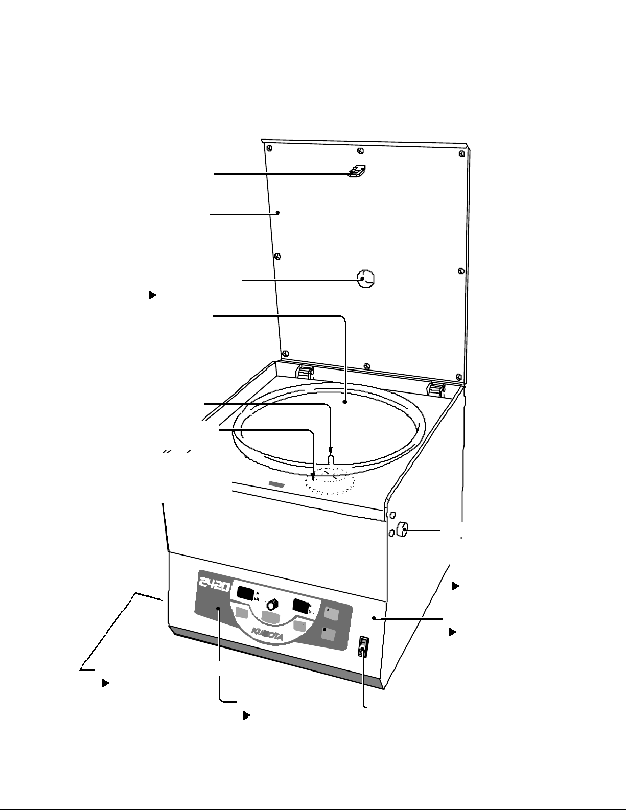
1-1
“
POWER"switch
Drive Shaft
Control panel
Chamber
Front co ver
Hook
Refer to Page 1-2.
Refer to Page 3-5.
Refer to Page 3-4.
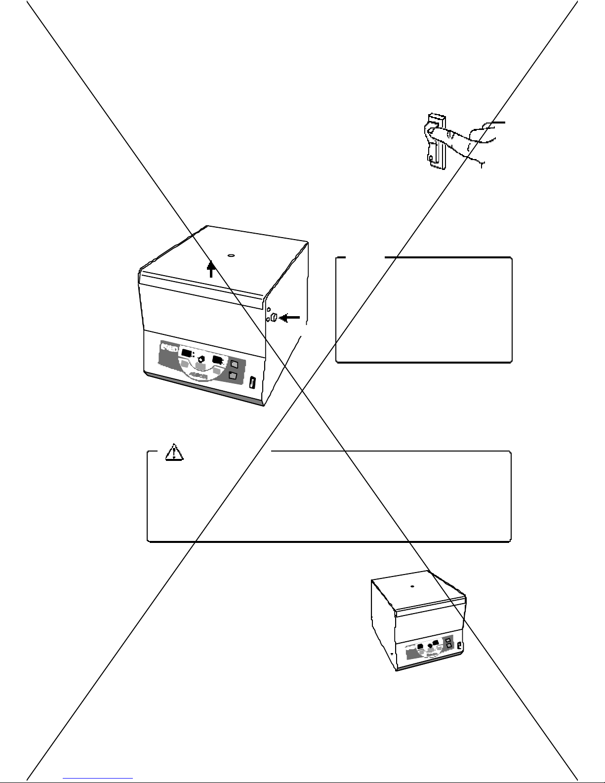
The lid opens when it i s
p
ushed during the operation
stop with the power on.
Lid
Tachometer port
Refer to Page 4-7.
“
OPEN”button
Refer to Page 3-4.
Lid extre me release ca
p
Bucket intervention
p
revention plate
This plate prevents the touch of
the b ucket .
Do not remove this pla te, when
y
ou remove the rotor.
Section 1
Component Name and Explanation
1 - 1.
A
pp
earance
Page 12
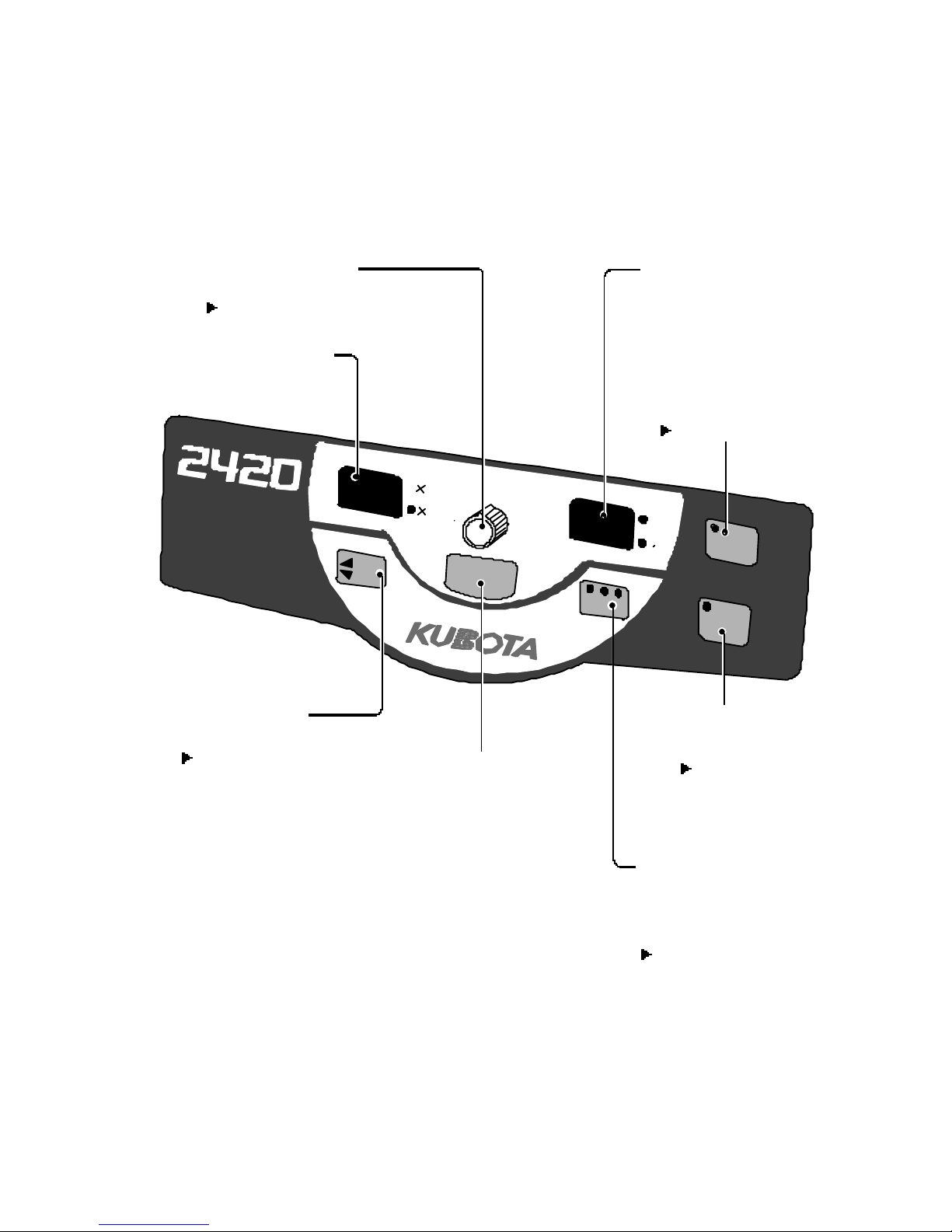
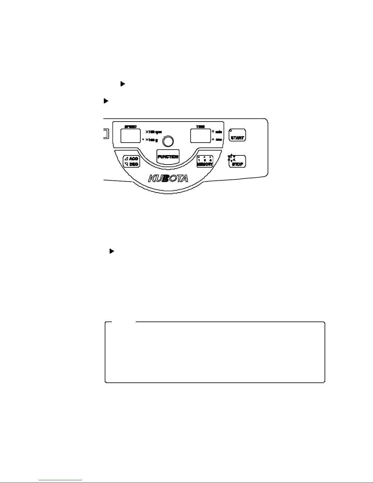
1-2
1-2.
Control Panel
Section1 Component Name and Explanation
S
T
A
R
T
S
T
O
P
T
I
M
E
m
i
n
s
e
c
S
P
E
E
D
1
0
0
r
p
m
1
0
0
g
M
E
M
O
R
Y
1
2
3
A
C
C
D
E
C
F
U
N
C
T
I
O
N
When this key is pressed
the operation will be
started.
“
START" ke
y
“
TIME" dis
play
“
STOP"ke
y
Press this key to
discontinue operation.
“
ACC / DEC" ke
y
“
FUNCTION" ke
y
This key allow the selection
of saved programs.
Pre s sing the key will light
the lamp.
MEMORY selection ke
y
“
SPEED" dis
play
“
SPEED/TIME"kno b
Refer to Page 3-10.
Refer to Page 3-2.
(
Setting the speed, RCF and time.
)
Refer to Page 3-9.
Refer to Page 3-2.
(
To change for ACC and DEC.
)
Refer to Page 3-6.
(
To c hange for speed /
RCF and time.
)
(Sp
eed / R CF
)
Page 13
2-1
Contd. o
n next
page
.
●
Never move the centrifu
g
e while the rotor is rotating or while the rotor is
attached to the centrifuge. Otherwise, the drive shaft may become bent
or the rotor and the bucket ma
y
com e o ff, res ulting in an a ccident or
damage to the centrifuge.
●
Ensure that rotor and bucket are removed from the centrifu
g
e and that
the power cord is disconnected from the wall socket.
●
Movin
g
the position of the centrifuge while the power is t urned on may
cau se e le ctrificati on acciden t or functi on al fail ure of the centrifuge.
WARNING
When installing this centrifuge, keep 3meters or more away from AM radio.
Noise
g
enerated by this centrifuge causes the sound of AM radio deteriorated.
A clearance of 30 cm minimum mus t be provided around the centrifuge.
If the centrifu
g
e is driven into uncontrolled rotations due to a failure, secondar
y
damage can result from energy absorbed by the rotation.
WARNING
Do not install the centrifuge on an inclined, slippery, or unstable surface.
Violent vibration ma
y
occur.
CAUTION
Section 2
Installation and Power Su
pply
2-1.
Unpackin
g
When the centrifuge is taken out of a corrugated carton box, check the following.
(1)
U
p
on receiving th e cen tri fuge, examine it for any visible damage caused during
trans
p
ortation.
If an
y
is found, contact the dealer immediately.
(2)
Confirm that all the accessories listed in
[
7 - 2. Standard Accessories] are included with
t he deliver
y
. Refer to page 7-1.
2-2.
Place of installation
2-3.
Movement of centrifuge
Page 14

2-2
■
When movin
g
the centrifuge, lift up the bottom of the centrifuge
body by two or more persons using equal f orces to move the
cent
rif
uge to the desired place
.
■
Do not dro
p
the centrifuge, othe rwise damage or injury may occur.
CAUTION
Prepare a power supply that meets the following conditions.
1. The
p
ower supply voltage must be the same as that indicated on the
name
p
late o f the centrifuge and the voltage va riation m ust be wi thin
the ran
ge g
iven in Table 2-1.
2. The current ca
p
acity must be more than giv en in Ta ble 2-1.
3. In connectin
g
the cord, install a knife switch or circuit breaker of given
value in Table 2-1.
When the centrifu
g
e is connected to an outlet by means of a plug, use
a 3-
p
in plug with a ground terminal.
4. Use sin
g
le-phase power.
5. The outlet m ust have a
g
round terminal and its ground resistance must
be les s than 100 ohm.
Table 2-1 Rated Voltage, Cu rrent and Acceptable Voltage Range and Current Requirement
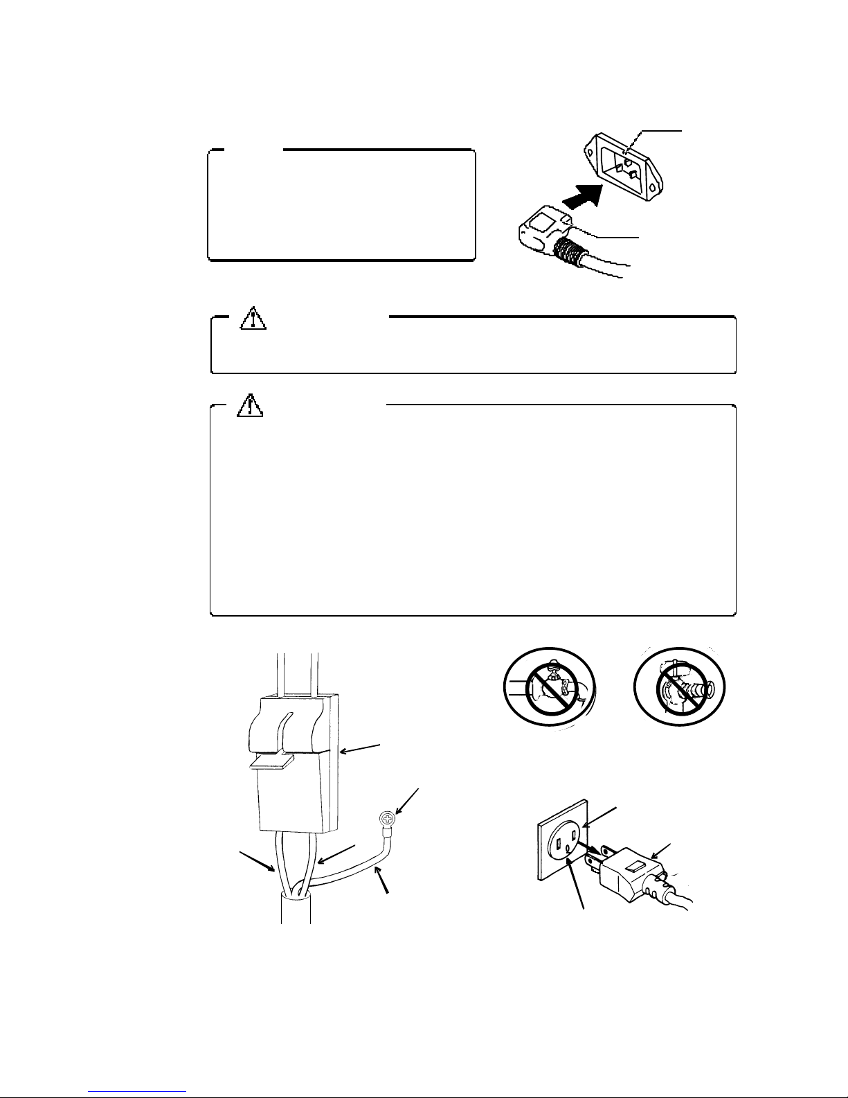
WARNING
●
The
p
ower cable alone should be connected to the plug socket.
●
Do not use a branched
plug
socket, which may cause overheating or fire.
WARNING
Rated Voltage 100-115V 200-240V
Acceptable Voltage Range 90V to 126V 180V to 264V
Current requirement 8A 5A
2-4.
Power Requirement
Section 2 Installation and Power Suppl
y
Page 15
2-3
Power plu
g
Inle
t
When using the cent rifuge for the
first time
, plug
the power cabl e on
the centrifuge into the inlet on the
back of the centrif u
g
e.
NOT E
Ensure that the ground wire is connected to t he grounding terminal.
WARNING
Do not connect the ground cable to the following pla ces:
1. Gas
piping
Ex
p
losion or fire may occur.
2. Ground cable of the li
g
htning conductor, or telephone cable. Electric
shock ma
y
occur in case of thunderbolt.
3. Water
pip
es
Cit
y
water pipes may not be adequate as a ground since it may be
connected to
p
lastic pipework.
WARNING
2-5.
Grounding
Section 2 Installation and Power Suppl
y
Plug Socket
Power plu
g
Ground terminal
Ground wire
(
Gree n- and -yellow stripe
p
attern
)
Ground terminal
Kni fe switch
Power
(White
)
Power
(
Bla ck
)
water pipes
Gas pipin
g
Page 16
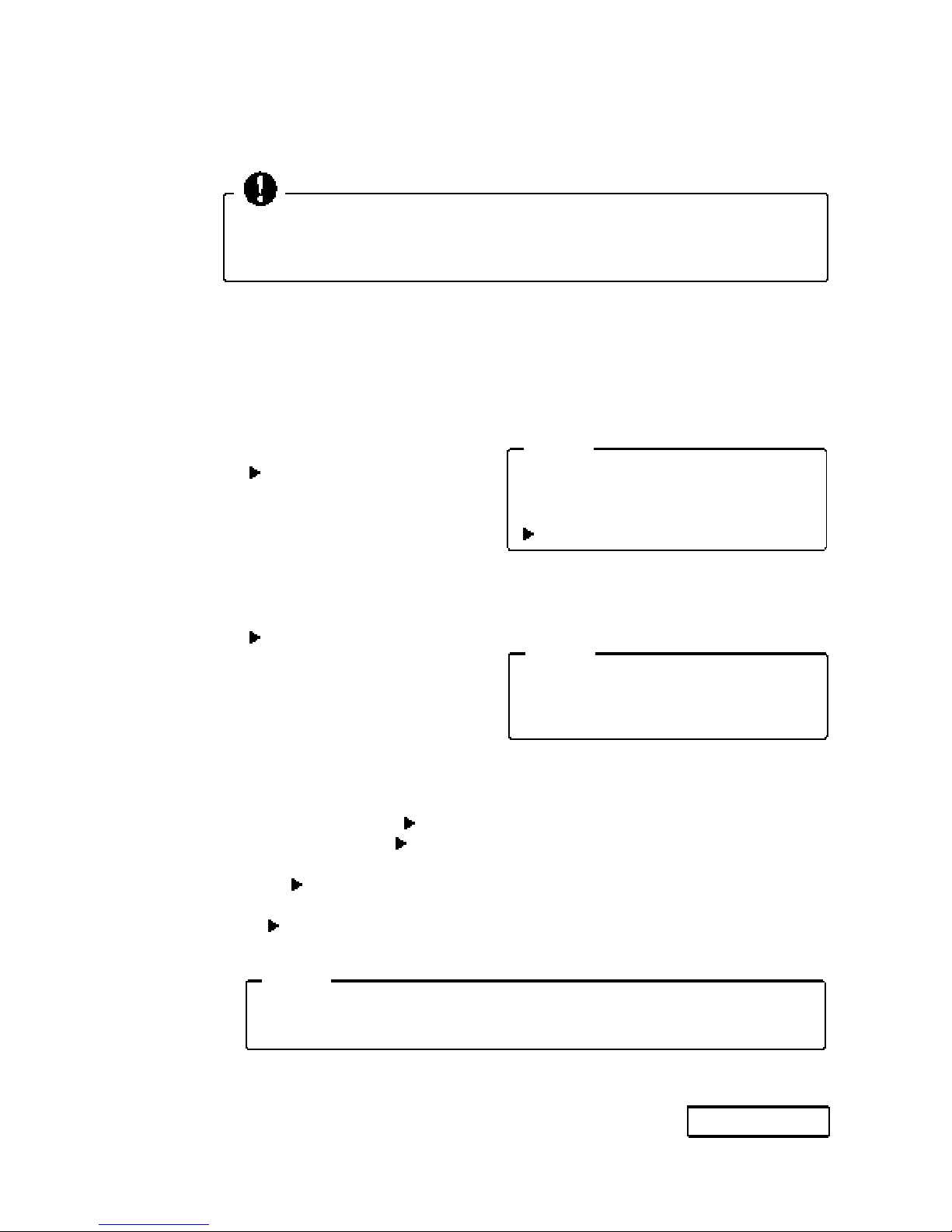
3-1
If the lid is not closed properly the
cent
rif
uge is not able to start
.
Make sure the lid is closed firml
y
.
NOT E
Install the rotor after checking if the
"Bucket intervention
p
revention plate" is
installed on the drive shaft.
Refer to page 1-1.
NOT E
Press the "SPEED/TIME" knob to check the "centrifugal force" of the set
s
p
eed or "speed" of the set centrifugal force.
NOT E
Contd. o
n next
page
.
When using this centrifuge, observe t he contents o f th e Sect io n "Ge neral
Note s" be ing described in the f ront part of this document and the
p
recaut ions give n in respective sections.
Section 3
Operation
3-1.
Cautions of Operation
3-2.
Operation
Operation 1. Turn on the “POWER" switch
.
O
p
eration 2.After the “STOP” lamp on the control pan e l l ights, press the “OPEN” button.
O
p
eration 3. Mount the rotor on the drive shaft.
Refer to Section 6.
O
p
eration 4.
For swin
ging
bucket rotor, mount bu ckets on the rotor .
O
p
eration 5. Place the sample in the rotor or buckets
.
Refer to Section 6.
O
p
eration 6. Close the lid firmly.
O
p
eration 7. Proceed to operation 9 when operating with the same setting values as before.
O
p
eration 8. Set the respective parameters.
・
Set to re
q
uired speed. Refer to page 3-6.
・
Set to re
q
uired time. Refer to page 3-8.
・
Set brakin
g
force during deceleration and acceleration speed with the“ACC/DEC”
ke
y
Refer to page 3-12.
●
When the memor
y
has been saved, press the selection key.
Refer to page 3-10.
Page 17
3-2
min
sec
min
sec
(1) When
y
ou want to change the setting (speed, RCF, time) during the operation.
Press the“FUNCTION" ke
y
1 or 2 times on the control panel after changing the
settin
g
, and the flashing of the display is stopped.
The o
p
eration becomes s hifted to the setting that have
been chan
g
ed.
START
STOP
(2)
When you want to halt operation, Press the“STOP" key
on the control
p
anel.
There is the sound and the rotor will come to a halt.
In case that the o
p
eration is stopped before the en d of the period set by the
timer and is resumed
,
the operation period after resumption is the remai ned
p
eriod of the operation.
If the knob is
p
ressed before resumption of operation, the operation period
returns to the ori
g
inal ly set period.
FUNCTION
Operation 9. Press th e“START"key.
“
Pi
p
"sound and lamp on th e“START" key lights.
Value on the “TIME” dis
play
starts decrea-
sin
g
.
When the value becomes 0
,
the centrifuge
automaticall
y
decelerates and stops.
O
p
eration 10.
***
In the followin
g
case
***
Sect ion 3 Operation
Page 18
3-3
NOTE
When the rotor has sto
pped,
the“STOP" l amp flashes and an sound that informs the end of
the o
p
eration is issued.
●
The “Sound that informs the end of the o
p
eration” can be selected from the 5 kinds +
So un d n one.
Refer to page 3-14.
●
The “Alarm Indicat ors” to show the end of the o
p
eration can be selected from the 5
kinds.
Refer to page 3-17.
O
p
eration 11. Press the“OPEN" button to open the lid.
“
STOP” lam
p
remains lit.
O
p
eration 12. Remove the sample.
Refer to page 3-16.
O
p
eration 13. If the centrifuge is to be used again, retu rn to Operation 5.
Operation 14. After finishing use of the centrifuge, turn "OFF" the "POWER" switch to turn off
the
p
ower s upply, leaving the lid i n opened state.
If the power is turned off while a memory being called up and is
then turned on a
g
ain, the same memory as di splayed before the
p
ower cut will be calle d up and displayed.
Ex. : Turn off the power while“MEMORY 2” called up. Turn on the power,
the“MEMORY 2” ke
y
lamp will light and the parameter stored under
“
MEMORY 2” ke
y
will be displayed.
Sect ion 3 Opera tion
Page 19
3-4
The lid is locked in following
cases and
will not
open eve
n if
the
〈
OPEN〉 button is pressed.
・
When the rotor is spinning.
・
When there is a power failure
or the
p
ower is turned off.
Do not open the lid while the rotor is spinning.
When a
p
ower failure occurs during operation of the centrifuge, the rotor
will naturall
y
decele rate to stop its rotation. If the lid is unlocked forcibly
before the rotor sto
ps,
the person can be entangled in the rotor, resulting
in a s erious in
jury
or death.
WARNING
S
T
A
R
T
S
T
O
P
T
IM
E
m
i
n
s
e
c
SP
E
E
D
10
0
r
p
m
1
0
0
g
M
EM
O
R
Y
1
2
3
A
C
C
D
E
C
FU
N
C
T
IO
N
“
OPEN” button
Open
NOTE
3-3.
Opening and Closing the lid
[1] Tu rning on the power and opening the l id
(1)
Turn on the the “POWER" switch to turn the
p
ower on.
The“POWER" switch locates on the front side
p
anel of
the centrifu
g
e.
(2)
The〈STOP〉 lam
p
on the control panel will be lit.
(3)
Press in
g
the〈OPEN〉 button the lid can be opened.
[2] Opening the lid during power failure
(1)
Turn off the “POWER” switch.
(2)
By using a flat-blade screwdriver, remove the lid
extreme release ca
p
on the lower part of the left
si de of the un it.
While pulling the string straight, push “OPEN”
button.
(
Do not pull the string too strong.)
Then t he lid o
p
ens.
Sect ion 3 Oper atio n
Strin
g
S
TA
RT
S
TO
P
T
IM
E
S
PE
ED
F
UN
CTI
ON
Page 20
3-5
The lid can be closed even
when th ere is a
p
ower failure
or the power is turned off
.
NOT E
For prevention of electric shock, wait at least 5 minutes before opening the
front lid.
◆
If the lid extreme release ca
p
string is cut
WARNING
(1)
Turn off the “POWER" switch.
(2)
Remove the
p
ower s upply plug from the outlet.
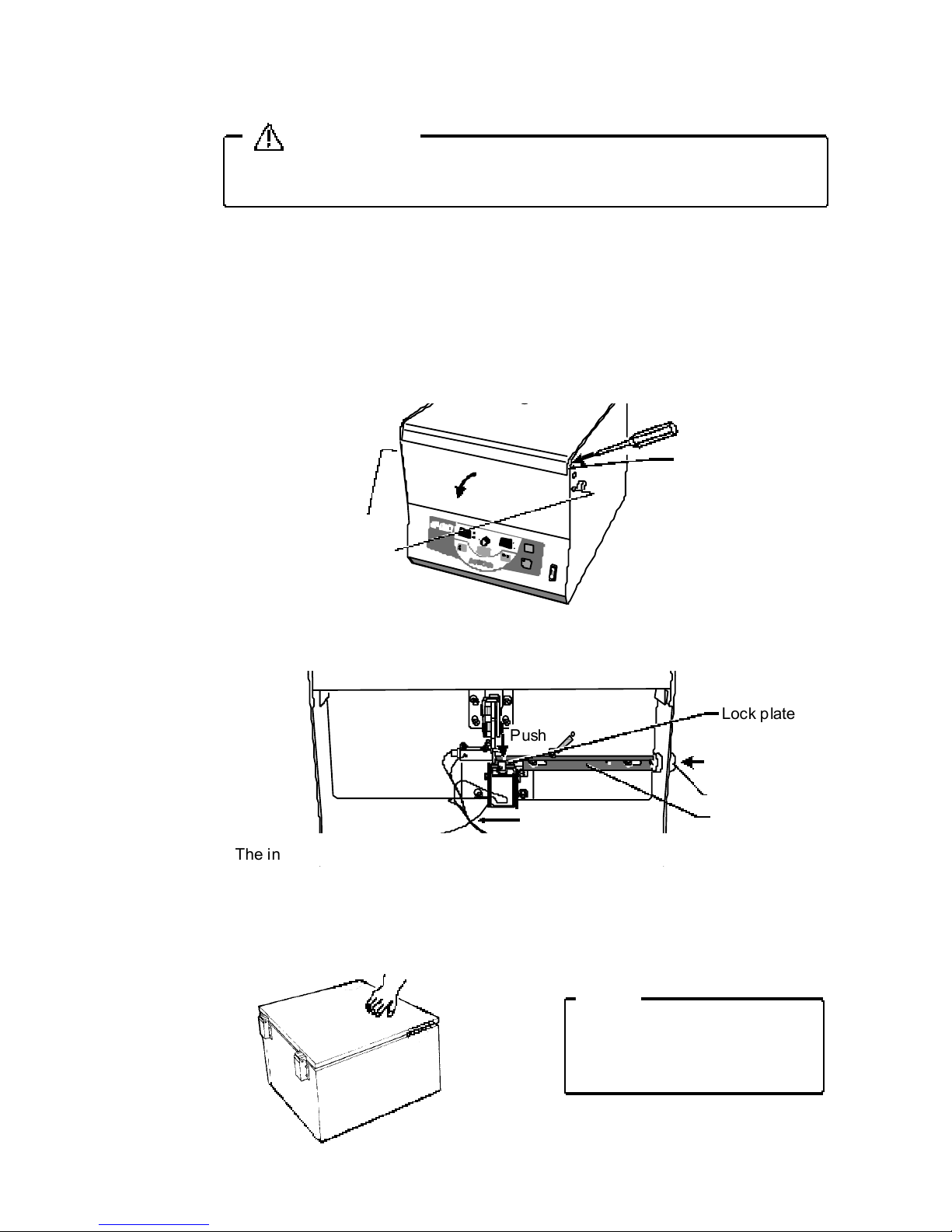
(3)
When more than 5 minutes hav e
p
assed after turning off th e power, remo ve the 2
screws on the left and the ri
g
ht si des of the centrifuge.
(4)
Insert a minus driver into the clearance between the front cover and the centri fu
g
e, and
tu rn the fr on t cover over
g
ently to the front side.
(5)
Press the “OPEN” button while holdin
g
down the lock plate.
The lid o
p
ens after the lid lock has been released.
[3] Closing the lid
Close the lid by pressing the front center of the li d by hands.
Press the lid securel
y
and lock it.
Sect ion 3 Oper atio n
S
T
A
R
T
S
TO
P
T
I
M
E
m
i
n
s
ec
S
PE
E
D
1
0
0
rp
m
1
0
0
g
M
E
MO
R
Y
1
2
3
A
C
C
D
E
C
F
U
N
C
TI
ON
Screws
(
two
)
Space
Minus driver
Lock plate
Push
The inside of t he centrifuge
Strin
g
(
When the string is cut, it can be fixed by
tying the ends.
)
Push
“
OPEN” button
Connection stick
Page 21

3-6
TIME
SPEED
10 0rpm
×
10 0
g
×
FUNCTION
10 0rpm
×
10 0
g
×
10 0rpm
×
10 0
g
×
10 0rpm
×
10 0
g
×
FUNCTION
min
sec
10 0rpm
×
10 0
g
×
SPEED
SPEED
SPEED
SPEED
●
The centrifuge can be started with the speed on the "SPEED" display,
even i f the dis
play
of val ue is flashing.
●
When
y
ou want to change the setting during the operation, press the
“
FUNCTION" ke
y
2 times on the control panel after changing the
settin
g,
and the flashing of the display is stopped.
The o
p
eration becomes s hifted to the setting that have been changed.
●
The setting order of the speed and the timer can be changed.
Refer to page 3-15.
NOT E
3-4.
Setting the Speed
[1] Setting the speed by the rpm
(1)
Press the“FUNCTION” ke
y
.
The“SPEED” dis
play
flashes and indicates the current setting.
(2)
Check if the
〈×
100
g
〉
lamp turned off.
①
When the
〈×
100
g
〉
lamp is off
・・・・・・・・・・・・・・・・・
Proceed to the Procedure
(3)
.
②
When the
〈×
100
g
〉
lam
p
is on
・・・・・・・・・・・・・・・・・・
Press the“SP EED/TIME”
knob and th e
〈×
100
g
〉
lam
p
turns off.
Proceed to the Procedure
(3)
.
(3)
Turn the“SPEED/TIME” knob to set t o re
q
uir ed speed.
The s
p
eed ca n be se t 100 rpm intervals.
(4)
When continuin
g
on to time setting, press the “FUNCTION” key.
The “SPEED” dis
play
stops flashing and the “TIME” display starts to flash.
(
Timer setting status
)
Sect ion 3 Operation
Page 22

3-7
TIME
10 0rpm
×
10 0
g
×
FUNCTION
10 0rpm
×
10 0
g
×
10 0rpm
×
10 0
g
×
1 00rpm
×
10 0
g
×
FUNCTION
min
sec
10 0rpm
×
10 0
g
×
SPEED
SPEED
SPEED
SPEED
SPEED
NOT E
●
The centrifuge can be started with the speed on the "SPEED" display,
even i f the dis
play
of val ue is flashing.
●
When
y
ou want to change the setting during the operation, press the
“
FUNCTION" ke
y
2 times on the control panel after changing the
settin
g,
and the flashing of the display is stopped.
The o
p
eration becomes s hifted to the setting that have been changed.
●
The setting order of the speed and the timer can be changed.
Refer to page 3-15.
[2]
Setting the speed by the centrifugal fo rce
(
×
g)
(1)
Press the“FUNCTION” key.
The“SPEED” dis
play
flashes and indicates the current setting.
(2)
Check if the
〈×
100
g
〉
lamp turned on.
①
When the
〈×
100
g
〉
lamp is on
・・・・・・・・・・・・・・
Proceed to the Procedure
(3)
.
②
When the
〈×
100
g
〉
lam
p
is off
・・・・・・・・・・・・・・
Press the“SP EED/TIME” knob
and the
〈×
100
g
〉
lamp turns
on.
Proceed to the Procedure
(3)
.
(3)
Turn the“SPEED/TIME” knob to set t o re
q
uir ed centrif ugal force reading.
Indications on the“SPEED” dis
play
are at 100
×
g
intervals.
(4)
When continuin
g
on to time setting, press the “FUNCTION” key.
The “SPEED” dis
play
stops flashing and the “TIME” display starts to flash.
(
Timer setting status
)
Sect ion 3 Opera tion
Page 23

3-8
min
sec
min
sec
FUNCTION
NOT E
●
In case that the operation is stopped before the end of the period set by the
timer and is resumed
,
the operation period after resumption is the remained
p
eriod of the operation.
If the "SPEED/TIME" knob is
p
ressed before resumption of operation, the
o
p
eration period returns to the origina lly set period.
●
The centrifu
g
e can be started at the time when th e setting value is flashing at
"TIME" dis
play
.
●
When
y
ou want to change the setting during the operation, press the
“
FUNCTION" ke
y
on the control panel af ter changing the setting, and the
flashin
g
of the display is stopped.
The o
p
eration becomes s hifted to the setting that have been changed.
●
The s
p
eed and the timer can be set in this sequence or vice versa.
As for the chan
g
e of the setting, please refer to page 3-15.
3-5.
Setting the Timer
(1)
Press ing the "FUNCTION" key 2 times, the“TIME” display flashes and indicates the
current settin
g
.
The timer is able to be set u
p
.
(2)
Press in
g
“
SP EE D /TI M E" k no b chan
g
es the settable range of centrifuging time as des-
cribed below. Set to the ran
g
e as requir ed.
Factor
y
default, the range is set minutes
.
③
HOLD
It will continuall
y op
erate regard les s of
the timer. When set to hold
,
both "min"
and "sec" lam
p
will be turn off.
(3)
Turnin
g
the“SPEE D/TI ME" knob changes
the indication on the dis
play
.
Set to the time re
q
uired.
(4)
Press“START" ke
y
on the control pan el .
The o
p
eration will be started.
When started
,
the display will diminish and stop at point 0.
Sect ion 3 Operation
②
Setting second s
①
Settin
g
minute s
Settable range 1-99 minutes
Setting unit 1 minute
Settable ran
g
e 1-99 seconds
Settin
g
unit 1 second
min
sec
min
sec
min
sec
Page 24

3-9
ACC
DEC
ACC
DEC
ACC
DEC
ACC
DEC
ACC:RAPID(
“
RAPID
”
acceleration
)
DEC:RAPID
(
“
RAPID”deceleration
)
ACC:RAPID
(
“
RAPID”acceleration
)
DEC:SLOW
(
“
SLOW” deceleration
)
ACC:SLOW
(
“
SLOW”acceleration
)
DEC:RAPID
(
“
RAPID”deceleration
)
ACC:SLOW
(
“
SLOW”acceleration
)
DEC:SLOW
(
“
SLOW”deceleration
)
On
Off
It changes to the SL OW characte ristic
from RAPID at 1
000rp
m.
Natural deceleration
1000rpm
N
[Ex.]
SPEED
RAPID
decele ration
SL O W
acceleration
RAPID
acceleration
SLOW
decel eration
You can set the natural deceleration startin
g sp
eed N.
Refer to page 3-13.
NOTE
TIME
3-6.
Setting the acceleration・deceleration
When blowing-up of samples is feared, adjust the acceleration and the
decel eration settin
g
b
y p
ressin
g
the“ACC/DEC” ke
y
Sect ion 3 Opera tion
Page 25

3-10
The paramet ers necessary for operation (speed, RCF, time, acceleration /
decel eration
,
etc.) can be stored as programs with MEMORY 1~3 keys.
NOTE
MEMORY
123
FUNCTION
About 3 seconds
MEM ORY
12
3
FUNCTION
ACC
DEC
Even if the power is turned o ff, the paramet ers set at the time of power off
remain stored.
The last settin
g
is displayed and can be operated.
NOTE
3-7.
Saving the Memory
Saving the set ting value enables operation with the same setting
value re
p
eatedly.
[1] Saving the Memory
(1)
Set the respective parameters.
Refer to the followin
g pag
e for the setting meth od .
[3-4.
Settin
g
the speed
]
Refer to Page 3-6.
[3-5.
Settin
g
the timer
]
Refer to Page 3-8.
[3-6.
Settin
g
the acceleration・deceleration] Refer to Page 3-9.
(2)
Press in
g
“FUNCTION” key, the s etting is settled.
(3)
Press in
g
"MEMORY" key, the lamp is lit, and choose
the lam
p
number you wa nt to save.
(4)
Kee
p p
ressing “FUNCTION” key until the buzzer
sounds.
(
Abou t 3 seconds)
(5)
Stored memories can be easil
y
recalled by press ing the
a
pprop
riate memory selection key.
[2]
Memory cancellation
Pressing the “Function” key or the “ACC/DEC” key, the normal setting mode
will be selected.
①
Pressin
g
the “Function” key.
The chan
g
e for speed / centrifugal force or time.
②
Pressin
g
the “ACC/DEC” key.
The chan
g
e for ACC a n d DEC.
Sect ion 3 Operation
Page 26

3-11
FUNCTION
100rpm
×
100 g
×
min
sec
SP EE D
TIME
100rpm
×
100 g
×
min
sec
SP EE D
TIME
100rpm
×
100 g
×
min
sec
SP EE D TIME
100rpm
×
100 g
×
min
sec
SP EE D TIME
100rpm
×
100 g
×
min
sec
SP EE D
TIME
100rpm
×
100 g
×
min
sec
SP EE D
TIME
100rpm
×
100 g
×
min
sec
SP EE D TIME
NOTE
The memor
y
lamp turns off temporarily, when you set the function while
settin
g
the memory operation in Model 2420. The lamp is lighted after the
settin
g
.
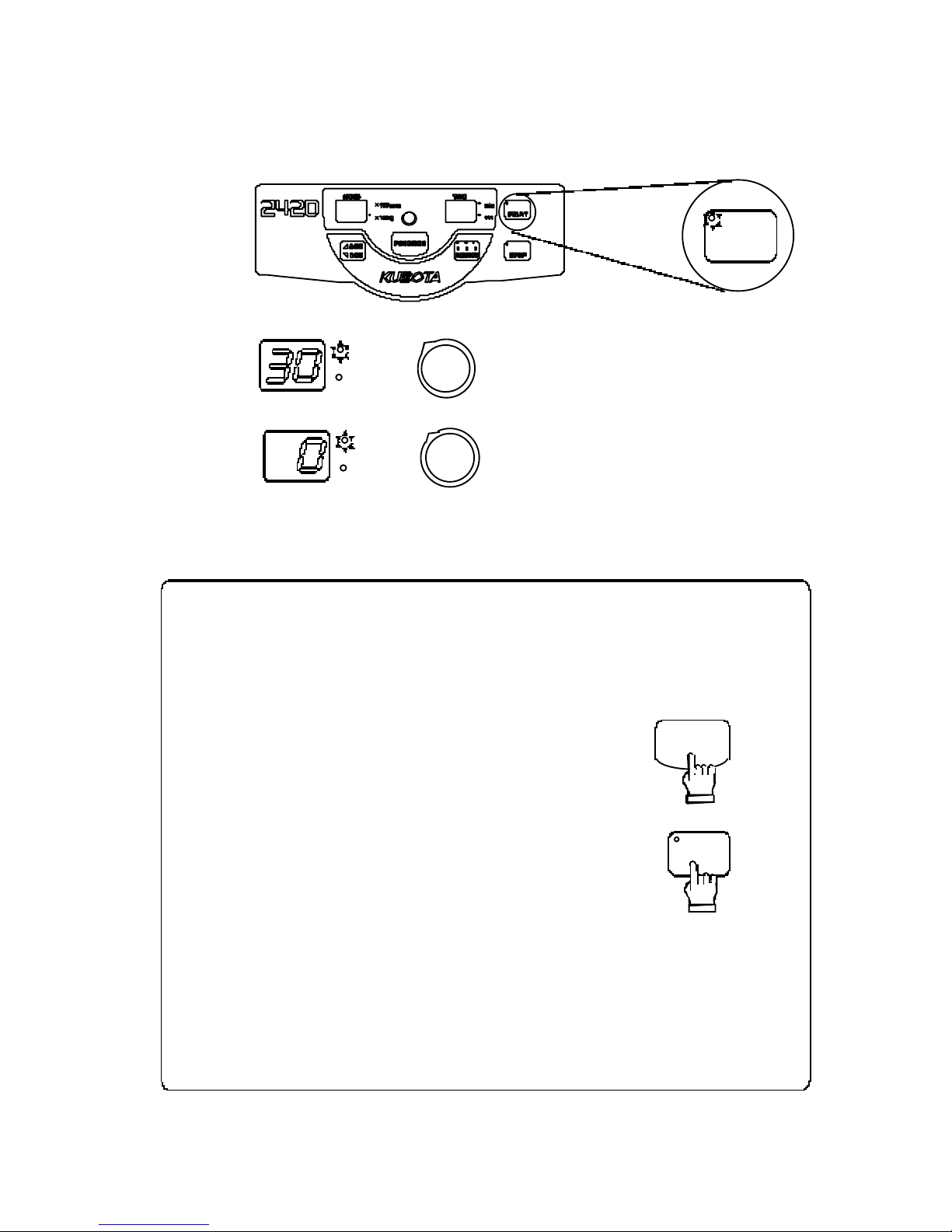
3-8.
Setting the Function
As fo r th is product the following setting is produced.
Choose the item
y
ou want to set up, and pres s "SPEED/ TIME" knob .
The
pag
e where the content is written is referred to.
(1)
Press in
g
the "SPEED/TIME" knob while holding
down the "FUNCTION" ke
y
.
(2)
The used number of times of the
centrifu
g
e is displayed.
[Ex.] 186 times
(3)
Settin
g
the Rotation Radius
Refer to Page 3-12.
[
Ex.]146 mm
(4)
Settin
g
the "SLOW" deceleration.
Refer to Page 3-13.
[
Ex.]300r
p
m
(5)
Settin
g
the Sound that informs the
en d of the o
p
eration.
Refer to Page 3-14.
[
Ex.]1
(6)
Reverse of settin
g
order of the
S
p
eed and the Timer.
Refer to Page 3-15.
[
Ex.]0
(7)
Settin
g
the Reminder alarm.
Refer to Page 3-16.
[
Ex.]ON
(8)
Settin
g
the Indicators for the end of
the o
p
eration.
Refer to Page 3-17.
[
Ex.]1
■
After settin
g
any one of the above, please return the display to the previous indication of
"SP EED" and "TIME".
To do ab ove
, p
ress the "SPEED/TIME" knob while holding down the "FUNCTION" key.
Sect ion 3 Opera tion
Page 27

3-12
FUNCTION
The rotation radius ca n not be stored in the memory, when th e power
su
pply
is turned off without returning the display to the previous
indication.
NOT E
100rpm
×
10 0
g
×
min
sec
SPEED TIME
10 0rpm
×
10 0
g
×
mi n
sec
SPEED
TIME
3 digit s 2 digit s 1 digit
[
Ex.]The rotation radius is 146 mm.
3 digit s
2 digit s
1 digit
FUNCTION
[1]
Setting the Rotation Radius
To obtain more accurate centrifugal force, adjust the rotation radius to that of the rotor
buckets.
Factor
y
default : 146 mm
.
(1)
Press ing the “SPEED/TIME” knob while holding
down the “FUNCTION” ke
y
.
The used number of times of the centrifu
g
e is displayed.
(2)
Press in
g
the "SPEED/TIME" knob several times and let indicate " " on the left side of
the “SPEED” dis
play
.
The “SPEED” and “TIME”dis
play
indicates the current setting.
Unit : mm
Refer to Page 3-11.
(3)
Turn the“SP EED/TIME” knob to set to the rotation radius of the rotor bucket to be
used for o
p
eration.
The ran
g
e is set from 5 0 to 150 mm
.
(4)
Press the “SPEED/TIME” knob while holdin
g
down the “FUNCTION" key.
The dis
play
returns to the previous Speed and Time indication after the setting (rotation
radius
)
is saved.
Sect ion 3 Operation
Page 28

3-13
100rpm
×
10 0
g
×
min
sec
SPEED TIME
10 0rpm
×
10 0
g
×
min
sec
SPEED TIME
FUNCTION
[2]
Setting the "SLOW" deceleration
The characteristics have become as shown in the graph.
You can set the natural deceleration startin
g sp
eed N by the following method.
Factor
y
default, it is set as 0 rpm
.
The settin
g
ra nge of "N" i s from 0 t o 4,000 rpm.
(1)
Press in
g
the "SPEED/TIME" knob while holding down the "FUNCTION" key.
The used number of times of the centrifu
g
e is displayed.
(2)
Press in
g
the "SPEED/TIME" knob several times and let indicate " "on the "TIME"
dis
play
.
The "SPEED" dis
play
indicates the current setting of the natural deceleration speed.
Unit : r
p
m
Refer to Page 3-11.
[
Ex.] Settin
g
is the 0 rpm.
(3)
Turn the "SPEED/TIME" knob to set the natural deceleration speed.
The settin
g
ra nge of "N" i s from 0 t o 4,000 rpm.
[
Ex.]Settin
g
the 300 rpm.
(4)
Press the "SPEED/TIME" knob wh ile holdin
g
down the "FUNCTION" key.
The dis
play
returns to the previous Speed and Time indication after the setting ( Natural
deceleration s
p
eed) is saved.
Sect ion 3 Opera tion
N
1000
N
1000
(A )N =
1,000 rpm or more
(B )N =
1,000 rpm or less
rpm
rpm
speed
It changes t o the SL OW
characteristi c from RAPID
at 100 0rpm.
RAPID
Natural
deceleration
SLOW
TIME
TIME
speed
RAPID
Natural
deceleration
Page 29

3-14
10 0rpm
×
10 0
g
×
min
sec
SPEED
TIME
10 0rpm
×
10 0
g
×
min
sec
SPEED
TIME
FUNCTION
[3]
Setting the Sound that informs the end of the operation
The
“
Sound that informs the end of the operation” can be selected from the 5
kinds + Sound none.
Use this function to identif
y
each “Sound that informs the end of the operation” when
y
ou use more than one centrifuges.
Factor
y
default : [1
]
(1)
Press in
g
the "SPEED/TIME" knob while holding down the "FUNCTION" key.
The used number of times of the centrifu
g
e is displayed.
(2)
Press in
g
the "SPEED/TIME" knob several times and let indicate " " on the "TIME"
dis
play
. The "SPEED" display indicates the current setting of the sound that informs.
Refer to Page 3-11.
[
Ex.]The “Sound that informs the end of the operation” 1.
(3)
Turn the "SPEED/TIME" knob to chan
g
e the "Sound that informs the end of the oper ation".
Press in
g
the "FUNCTION" key makes the selected buzzer sound once.
The "Sound that informs the end of the o
p
eration" can be selected from 1, 2,3, 4,
5 of 5 kinds + 0
(
Sound none).
(4)
Then,
p
ress the "SPEED/TIME" knob while holding down the "FUNC TION" key.
The dis
play
returns to the previo us Speed and Time indication after the setting ( S oun d
that informs the end of the o
p
eration) is saved.
Sect ion 3 Operation
Page 30

3-15
10 0rpm
×
10 0
g
×
mi n
sec
SPEED TIME
10 0rpm
×
10 0
g
×
min
sec
SPEED TIME
FUNCTION
Numbers Content s
0
「
Speed / RCF
」→「
Timer
」
1
「
Timer
」→「
S
p
eed / RCF
」
[4]
Reverse of setting order of the Speed and the Timer
The setting order of the speed and the timer can be reversed.
This function is useful when
y
ou often operate the centrifuge by changing the
timer onl
y
.
Factor
y
default : [0
]
(1)
Press in
g
the "SPEED/TIME" knob while holding down the "FUNCTION" key.
The used number of times of the centrifu
g
e is displayed.
(2)
Press in
g
the "SPEED/TIME" knob several times and let indicate " " on the "TIME"
dis
play
. Th e " SPEED" d isplay indicates the current s etting of the number (see the figure
below
)
.
Refer to Page 3-11.
[Ex.]Numbers 0
(3)
Turn the " SPEED/TIME" knob to chan
g
e the number.
(4)
Press the "SPEED/TIME" knob wh ile holdin
g
down the "FUNCTION" key.
The dis
play
returns to the previo us Speed and Time indication after the setting (Numbers)
is saved.
Sect ion 3 Opera tion
Page 31

3-16
10 0rpm
×
1
00 g
×
min
sec
SPEED TIME
10 0rpm
×
10 0
g
×
min
sec
S
PEED
TIME
FUNCTION
Reminder alarm
“
SPEED” dis
play
.
○
×
[5]
Setting the Reminder alarm
The alarm reminds the u ser every minute when samples are left in side the
centrifu
g
e after completion of the operation.
The reminder alarm
g
oes off when opening the lid or performing some operations.
Factor
y
default : [ON
]
(1)
Press in
g
the "SPEED/TIME" knob while holding down the "FUNCTION" key.
The used number of times of the centrifu
g
e is displayed.
(2)
Press in
g
the "SPEED/TIME" knob several times and let indicate " " on the "TIME"
dis
play
.Th e "SP EED" display indicates the current setting of the reminder on or off.
(
see the figure below
)
Refer to Page 3-11.
[Ex.]Reminder alarm : ON
(3)
Turn the " SPEED/TIME" knob to chan
g
e the number.
[Ex.]Reminder alarm : OFF
(4)
Press the "SPEED/TIME" knob wh ile holdin
g
down the "FUNCTION" key.
The dis
play
returns to the previous Speed and Time indication after the setting (reminder
on or off
)
is saved.
Sect ion 3 Operation
Page 32

3-17
10 0rpm
×
10 0
g
×
min
sec
SPEED TIME
10 0rpm
×
10 0
g
×
min
sec
SPEED
TIME
FUNCTION
Numbers
“
SPEED” and “TIME” displa
y
0
After [Setting value] lights
、[0]
lights
1
After [Setting value] flashin
g
、[0]
flashin
g
2
[8 8][8 8]
flashin
g
3
[--][- -]
flashin
g
4
[E ][nd]
flashin
g
[6]
Setting the Indicators for the end of the operation
Completion of the operation is indicated not only with an alarm but also with the
"SPEED" and "TIME" dis
play
s.
The "Alarm Indicators" can be selected from the 5 kinds.
Factor
y
default : [1] (see the figure below).
(1)
Press in
g
the "SPEED/TIME" knob while holding down the "FUNCTION" key.
The used number of times of the centrifu
g
e is displayed.
(2)
Press in
g
the "SPEED/TIME" knob several times and let indicate " " on the "TIME"
dis
play
. The "SPEED" display indicates the current setting of the n um ber (see the figure
below
)
. Refer to Page 3-11.
[Ex.]Number : 1
(3)
Turn the " SPEED/TIME" knob to chan
g
e the number.
(4)
Press the "SPEED/TIME" knob wh ile holdin
g
down the "FUNCTION" key.
The dis
play
returns to the previo us Speed and Time indication after the setting (Numbers)
is saved.
Sect ion 3 Opera tion
Page 33

3-18
Allowable load (gram
)
Actual load (gram
)
Reduced maximum speed(rpm
)=
Maximum speed(rpm
)×
Do not ex
ceed the ma
ximum
speed and the allowable load o
f r
otor and
bucket.
An excessive s
p
eed or overload may cause a damage to the rotor, bucket
and the cent
rif
uge
.
If the load exceeds the limit
,
reduce the maximum speed as shown in the
formula 3-2 and set the actual speed below the reduced maximum speed.
[
formula 3-2
]
As for rotation radius, please refer the page 6-4, 6-5, 6-10 and 6-12. The
maximu m cen trifu
g
al force being indicated in the said pages is calculate by
substitutin
g
the maximum radius of gyration of the rotor for the radius of
gy
ration of each rotor (cm) and by rounding the first digit above the decimal
p
oint of the calculation result.
B
y
setting the rotation radius, an accurate speed and centrifugal force can be
switched. Factor
y
default at the time of delivery is 14.6 cm.
Refer to page 3-12.
(1)
When the gravity of sample is 1.2 or higher or when a speci al tube is used
,
check t he allowable loa d of the rotor and bucke t.
(2)
Regarding allowable load on rotors and buckets at the maximum speed refer to the
appropriate Specification Table for rotor in use.
(3)
The allowable load includes t he weight of sample, cushions, adaptors, tubes, caps,
and racks. (The weight of bucket is not included in the allowable load.
)
WARNING
NOT E
3-9.
Calculating Centrifugal Force
You can readily calculate the centrifugal force by as signing the Rotation Radius and speed
in the followin
g eq
uation:
Please refer to the Nomo
grap
h for Centrifugal Force Calculation at the last page of this
man ual.
3-10.
Allowable load and Reduced maximum speed
Sect ion 3 Operation
entri fugal force RCF
(
×
g
)
= 11.18
×
S
p
eed N(rpm
)
1000
2
×
Rotation Radius R
(cm)
[
formula 3-1
]
Page 34

4-1
If any abnormality is found during routine daily inspections, discontinue
centrifu
g
e operation, use the "POWER" switch to turn the machine OFF,
disconnect the
p
ower cable, attach "DO NOT USE" labels to the rotor and the
outside of the centrifu
g
e, and contact your nearest deal er to request a c entrifuge
ins
p
ection before resuming operation of the equipment.
If the centrifu
g
e is used after discovering any abnormality, an accident could
occur,
p
ossibly leading to serious damage or accidents involving physica l injury.
WARNING
Checkpoint Action taken
Check whether the rotor knob
and rotor lockin
g
nut are
prop
erly tight.
Reti
g
hten, if either of these is loose. For details, refer
to "Mountin
g
the Rotor" in the rotor instruction
manual. Refer to Section 6.
To inspect, mount buckets on
the swinging bucket rotor
when it is sto
pped,
and lift up
the buckets manually.
If the buckets do not move smoothl
y
and freely, clean
the bucket grooves and trunnion pins of the rotor yoke
using alcohol. Contact your local dealer and make an
a
pp
ointment fo r an authorized i nspection if t hese
p
arts fail to operate smoothly even after lubricant has
been a
pp
lied. Refer to Page 4-5.
Check carefull
y
for any
cracks
,
evidence of corrosion
,
rust or deformation on the
rotor and bucke ts.
Do not use the rotor or buckets if an
y
cracks,
corrosion, rust or deformations are found. Contact
y
our local dealer for an inspection.
Check that no forei
g
n material
or water is present in the
chamber.
Remove an
y
foreign m a terial or water b e fo re
operating the centrifuge.
Check that the lid is hook.
If the lid lock does not work
,
discontinue operation of
the centrifuge. Contact your nearest dealer for a
centrifuge inspection.
Check that the screws fixin
g
the lid hinges are not loose.
If the screws fixin
g
the lid hinge ar e loose or have
been removed, the lid may come off when the buckets
are thrown off and the broken pieces may cause injur
y
to the persons in the vicinity of the centrifuge. If the
lid hinge is not fixed firmly, stop centrifuge
operation. Stop operation promptly and contact
y
our
loca l de aler for inspe ction.
Check the nut of the trunnion
p
in (RMP-23) is not
loosen ed.
If the trunnion
p
in is loosened, contact your local
d e al er fo r in spection.
Check that t he
g
rounding wire
is cor rectly connected.
Refer to Page 2- 3 .
Check that all knobs,
displays, lamps and switches
o
p
erate correctly.
If an
y
do not operate correctly, contact your local
d e al er fo r an in spection.
Refer to Page 1-1 and 1-2.
Check that the centrifu
g
e is
p
laced horizontally.
Refer to
page
2-1.
Section 4
Service
4-1.
Daily Inspection
Page 35

4-2
WARNING
Perform a monthly careful inspection of the rotor appearance. Check for
an
y
deformation or damage, inc luding the interior and bottom of the holes.
If an
y
abnormality whatsoever is found , there may be significant damage or
corrosion of the rotor that could lead to serious dama
g
e or accidents
involvin
g phy
sical injury. Stop operation a t once, put "DO NOT USE" labels
on the rotor an d centrifu
g
e lid, and contact your local deal er to arrange for
authorized service.
Motor S
p
eed control
Rotor and b ucket Imbalanc e
lid Electric current
Chamber Insulat ion
S
p
eed meter Install the centrifuge
Timer
4-2.
Monthly Inspections
[1]
Ins
p
ect the rotor
[2]
Clean the rotor and buckets
Remove the rotor from the shaft, and clean it.
Refer to Page 4-3.
[3]
Clean the chamber interior
Refer to Page 4-3.
4- 3.
Annual Inspection
Annual Inspection (fee required
)
For the following inspection i tems, please call your local deal er and set up an
a
pp
ointment for a periodical inspection.
Sect ion 4 Ser vice
Page 36

4-3
Contd. on next page.
Consult with your nearest dealer prior to attempting any cleaning procedure for
the rotor, bu ckets, or tube rack that is n ot s
p
ecifically recommended in this
manual. Certain cleanin
g
methods or cleaning agents may cause corrosion and
then breaka
g
e leading to serious damage or accidents involving physical injury.
WARNING
4-4.
Cleaning and Sterilization
[1]
Cleaning the chamber interior
The chamber i s made of stainless steel (SUS304) but may rust if sample spillage
contai nin
g
sal t (NaCl) or chlorinated chemicals (Cl) is allowed to remain.
After u sin
g
the centrifuge, follow the method below (1) when wiping the inside of
the chamb er and cleani n
g
the surfaces.
(1)
Cleaning and rust prevention
Cleaning the chamber interior according to the following procedure will he lp
p
reve nt rust.
1
)Wip
e off any di rt or res idu e usi ng a cloth moistened with a small quantity of a neutral
deter
g
ent.
2
)Wip
e away any detergent residue using a cloth dampened with water, and then dry the
inside of the chamber.
3
)
To prevent rust, we recommend the use of common anti-rust agents (such as CRC-556)
onl
y
if such will not affect the samples being centrifuged.
Wi
p
e the dirt off using a cloth containing a small quantity of neutral detergent.
(2)
If rust is
p
resent
Superficial rust can be removed by using a mild solution of sodium bicarbonate
(
NaHCO3, bica rbonate of soda, baking so da).
1
)
Moisten a paper towel with a little water, apply some bicarbonate of soda, and then rub the
area where rustin
g
has occurred.
2
)
After removing the rust with the bicarbonate of soda, follow the above procedure (1) and
clean the chamber interior usin
g
a neut ral detergent followed by a thorough wiping with
p
lain water. Make sure that such cleaning is especially thorough, so that all traces of the
bicarbonate of soda are rem ove d .
[
NOTE
]
Under no circumstances should an
y
rust inside the chamber be removed by using
sand
pap
er or abrasive agents, since if the interior surfaces are scratched, this will
onl
y
increase the likelihood of additional rust developing.
Sect ion 4 Servi ce
Page 37

4-4
Do not al low any spilt samples to remain on any surfaces, otherwise rust
or corrosion ma
y
occur. Also, if sample spillage is left between the rotor
and shaft, later detachment of the rotor may become pro blematic.
WARNING
Do not heat the rotor, buckets, or tube rack above 100℃ for sterilizatio n
or disinf ection
purp
ose s.
Al
so, do not use an autoclave for dry heat ste
rilization, since ex
cessive
heat ma
y
deleteriously affect the strength of the rotor, buckets, or tube
rack, r
esulting
in break
age of the rotor, buckets, or tube rack, causing
seri ou s dama
g
e or accidents involving physical injury.
Yet
,
You can conduct up to 50 times of autoclave sterilizations of the
RMP-23 rotor and bu cket at 121 ℃ and 100 times of autoclave sterilizations
of the RS-1004 rotor and bucket at 121 ℃.
Do not use deter
g
ents exceeding a pH range of 5 - 8, or chlorinated
deter
g
ents normally used for washing.
Corrosion ma
y
damage the rotor, bucket, or tube rack, resulting in damage
to the centrifu
g
e that may lead to serious ad ditional damage or accidents
involvin
g phy
sica l injury.
CAUTION
NOT E
[2]
Cleaning the rotor, buckets and tube rack
1)If s ample spillage has occurred, remove the rotor, buckets, and tube rack from the
centrifu
g
e, and wash the affected items with a neutral detergent and warm water.
Then rinse the items with the distilled water and thorou
ghly
dry them before use.
2
)
If water has accumulated inside the rotor, place the rotor with its bottom side up and allow
it to dr
y
completely.
3
)
If a sample has spilled onto the drive shaft, wipe it off using a cloth moistened wi th a
small amount of a neutral deter
g
ent and then clean away all detergent traces using a cloth
moistened with water. Then, dr
y
the surfaces completely before using the machine.
[3]
Sterilization of rotor, buckets and tube rack
To disinfect the rotor, buckets, or tu be r ack, a 70% ethanol solution, or ultraviolet
radiation, is recommended.
Sect ion 4 Servi ce
Page 38

4-5
Roto r yoke
Tr
u
nnion pin
1)If the buckets do not swing up smoothly as the rotor is spun up to
s
p
eed, apply the attached grease to the section A shown in sketch
belo
w. The
buckets should then s
wing up sm
oothly
.
2
)Wip
e off any dirt or congealed material before applying fresh grease,
usin
g
alcohol or acetone.
3
)
If the buckets do not swing up properly after applying the grease,
contact
y
our local dealer for an inspection.
4
)
When the provided grease is used up, purchase replacement grease of
the followin
g
code number from your nearest local dealer.
Be careful to maintain lubrication by ensuring that a proper amount of grease is
p
resent in all bucket grooves (section "A" in th e schemat ic diagram below). A
lack of
g
re ase m ay allow violent vibration to occur, resulting in damage to the
centrifu
g
e.
CAUTION
NOTE
Apply the
attached
g
rease
A
Rotor Grease code No.
RMP-23
RS-1004
S70284
4-5.
Greasing
Sect ion 4 Serv ice
Page 39

4-6
Circuit protector
4-6.
Inspection of Circuit Protector
The circuit protector is automatically activated when the electric circuit failure or
overcurrent occur.
In such a case, the white portion of th e circuit protector, located at the bottom left on the
rear side of the centrifu
g
e, will stick out.
Recover
y p
rocedure is as follows :
(1)
Turn off the power s witch.
(2)
After the rotor s to
p
s completely, open the lid and check the rotor, following
the
p
rocedure given in [3 - 3. Opening and Closing the lid 2. Opening the lid during
p
ower failure] on Page 3 - 4.
(3)
Close the lid , and then push the sticking out white portion until it becomes unseen.
(4)
Turn on the
p
ower switch.
(5)
Re - start operation and see if it works.
If the circuit
p
rotector is activated again, contact your local dealer.
Sect ion 4 Servi ce
Page 40

4-7
Do not apply force to th e tachometer port window from inside the lid.
4-7.
Using the Photoelectric Tachometer Port
A tachometer port (transpare nt window) is provided at the top of the lid.
Through th e tachometer port, the actual rate of rotati on can be measured,
using a photoelectric tachomete
r.
(1)
When usi ng a photoelectric tachometer, place a piece of reflective tape 5 - 20mm away
from the center of the rotor.
(2)
Mount the rotor on the drive shaft.
Refer to Section 6.
(3)
After turnin
g
the power ON, set the photoelectric tachometer so that its tip is right above
the tachometer
p
ort on the lid. The photoelectric tachometer can then measure the actual
rotation rate.
Sect ion 4 Ser vice
T
achomete r port
Lid
Cent rifuge
Photoelectric tachometer
20m
m
5mm
Reflective tape
Page 41

4-8
We cannot repair or inspect a centrifuge if it has not been properly
washed or sterilized beforehand, or if it has been used i n an RI facilit
y
or a
facilit
y op
erating at a level higher than P2. Please ensure that each
machi ne has be en
prop
erly washed and sterilized before offering it for
re
p
air or inspecti on.
Spare parts (parts necessary to the maintenance of equipment functions)
will be available for seven
(7) y
ears afte r production of the particular
p
roduct is discontinued. We therefore beg your indulgence and
recommend that
y
ou be prepared for some situations in which certain
re
p
airs are impossible due t o a lack of spare parts.
NOT E
Necessary information Note
1.
Model 2420
2.
Serial number
No.
See the name label at the left s ide panel of centrifuge.
3.
Trouble Provide a descri
p
tion of the trouble as detailed as
p
oss ible.
1.
Environment where the centrifuge is used.
2.
Sample
3.
Re
q
uired measures against the biohazard.
4-8.
Spare Parts Supply
4-9.
Manufacturer requirements at
Repair or Maintenance
[1]
Required information when submitting an inquir
y
[2]
Required information that must be attached to the centrifuge in the
form of a note
(1)
If
y
ou have pertinent information on your handling of biohazards, fill out the
items below
,
and affix this information to the centrifuge.
(2)
Ple ase at tach a " Contami na nt Elimination Ce rtificate " t o the cent rifuge.
Refer to Page 4-9 and 4-10.
Sect ion 4 Servi ce
Page 42

4-9
4-10.
Product Preparation When Returning
Units for Repair or for Other Reasons
[1]
Remove any contaminants from units or items that will be returned for
servicin
g
Prior to sending back our produ cts (including accessories) for repair or for other
reas on s, b e sur e to rem ove an
y
and all contaminants.
[2]
Attach a Contaminant Elimination Certificate
To eliminate possibly harmful contaminants, the user must take appropriate action on
his or her initiative. Fill out a "Contaminant Elimination Certificate" as shown on
pag
e
4-11
,
and attach it to the item to be returned.
[
Caution
]
"Contaminant" means radioactive materials, poisonous materials, contagious pathogen s
,
and so on. The preparatory procedure to eliminate all traces of such contaminants
therefore varies de
p
ending on the respective materials. P lease take appropriate action to
p
revent any possible hazard to personnel who will be handing the machine, equipment
or
p
arts.
[3]
Equipment contamination elimination goal
The elimination of contaminants from the equipmen t is aimed to safeguar d the persons
who will ins
p
ect and repair the returned products at our facilities.
[4]
If a Contaminant Elimination Certificate is not attached:
If a "Contaminant Elimination Certificate" is not attached to the returned products we
receive
,
we will contact the person in charge to confirm the details.
If we cannot confirm that potentially hazardous contaminants have been proper ly
eliminated
,
and we find that we cannot adequately deal with such matters ourselves, we
ma
y
return the products to the customer without taking further action .
[5]
Contaminant elimination fee
If we are forced to perform the work of eliminating contaminants, we may request that
y
ou pay a fee. Please note this stipulatio n beforeha n d.
Sect ion 4 Serv ice
Page 43

4-10
Please make a copy of this page and fill out the relevant details.
Contaminant Elimination Certificate
Date :
,
,
Name:
Company / Institute:
Department:
Tel:
Fax:
Address:
We hereby certify that contaminant elimination for this equipme nt has been
p
erformed as follows:
T
yp
e of un i t:
Serial No.
Type of un i t:
Serial No.
Accessories :
Date when contamination el imination was carried out.
Date:
,
,
Contaminants:
Method used:
Dealer notification:
Signature:
Page 44

5-1
The equipment is inoperat ive while any of the alarm indicators is turned on.
NOT E
“
TIME"displa
y
[
Ex.
]
Control panel
min
sec
TIME
Cont’d. on next page.
Alarm
Indicators
Check
p
oint Action taken
E0
Setting speed alarm
An error occurs immediatel
y
after
th e "ST ART" ke
y
is pressed when
the s
p
eed is more than 4,000 rpm
(
this may happen when centrifugal
force after chan
ging
rotation
radius is chan
g
ed to speed).
Pressin
g
the “START” key
makes the centrifu
g
e auto-correct
the s
p
eed to 4,000 rpm.
Section 5
Troubleshootin
g
5-1.
Alarm Indicators
(1)
When trouble occurs during operation, the “TIME" display flashes to indicate the alarm.
(2)
When an
y
of the alarms become activated during operation (when the rotor is spin-
nin
g)
, the rotor immediately decelerates and stops.
Page 45

5-2
"Alarm Indicators" and "Number of times of rotor use" at the time of rotor inspection
Alarm
Indicators
Check
p
oint Action taken
C1
C2
C3
C4
C5
Time alarm for rotor inspectio n
Because the ins
p
ection time has
arrived, the alarm is dis
play
ed.
1-5 re
p
resents the level of the number
of times of rotor use.
As for the details,
p
lease refer to the
followin
g
.
The ins
p
ection time for the rotor has
arrived.
Contact
y
our nearest dealer for
ins
p
ection of the rotor and bucket.
Alarm
Indicators
Number of times of rotor use at
the time of the alarm indicators
C1 50
,
000~50,050
C2 80
,
000~80,050
C3 100,000~109,999
C4 110
,
000~119,999
C5 From 120
,
000
Each "Alarm I nd icator" is displayed at the time when the number of times of rotor use reaches
the fi
g
ures shown below.
Section 5 Troubleshootin
g
Page 46

5-3
“
TIME"displa
y
[
Ex.
]
Control panel
min
sec
TIME
The equipment is inoperat ive while any of the error indicators is turned on.
NOT E
Cont’d. on next page.
Error
Indicators
Check
p
oint Action taken
E1
Imbalanc e error
This indicator flashes and the
rotor sto
p
s rotation when
excess ive vibration is
detected.
①
Balance the load
(
samples or bucket).
②
Remove dust and dirt from the slidin
g
surface and a
pply g
rease so that the bucket
on the swin
g
rotor swings up smoothly.
Contact
y
our local dealer for inspection when
this error continues to flash even after takin
g
the above measures.
E2
Lid open error
This indicator li
g
hts wh en
the lid is o
p
en.
Close the lid com
p
letely.
When the error recurs, contact
y
our nearest
deale r fo r ins
p
ection.
E3
Inverter Error
This indicator flashes when
abnormal si
g
nal comes out
from the inverter.
After the rotor sto
p
s spinning, tu rn of f power
su
pply
once and turn on the power after about
30 s econd s.
When the error recurs
,
contact your nearest
deale r fo r ins
p
ection.
5-2.
Error Indicators
(1)
When trouble occurs during operation, the “TIME" display flashes to show the error. The
error indicators are mentioned in the table below.
(2)
When an
y
of the error indicators turn on during operation (when the rotor is spinnin
g),
the rotor immediatel
y
decelerates and st ops.
Section 5 Troubleshootin
g
Page 47

5-4
Error
Indicators
Check
p
oint Action taken
E4
Speed sensor error
This indicator flashes when the
self-ins
p
ection function detects the
fault or ab normalit
y
in the speed
sensor.
After the rotor sto
p
s spinning, turn
off
p
ower supply once and turn on
the
p
ower after about 30 seconds.
When the error recurs, contact
y
our
nearest dealer for ins
p
ection.
E6
Over speed error
Flashes to sto
p
the rotation when
th e maximum s
p
eed of the
corres
p
onding rotor is exceeded.
Cont act
y
our local dealer for
ins
p
ection when this error
continues to flash.
E7
Speed error
This code a
pp
ears when the
e
quip
ment did not start its
o
p
eration wit hin 5 seconds after
the "START" ke
y
was pressed by
such causes as electric circuit
failures.
After the rotor sto
p
s spinning, turn
off the
p
ower s upply once and turn
on the
p
ower after about 30
seconds.
If the error recurs, contact
y
our
nearest dealer for ins
p
ection.
Section 5 Troubleshootin
g
Page 48

5-5
5-3.
Troubleshootin
g
Note 1: Read [2-4. Power Requirements] on page 2-3.
Note 2: Read
[
3-3. Opening and Closing the lid] on page 3-4.
Section 5 Troubleshootin
g
Problem
Checkpoint Action taken
1. The “STOP”
ke
y
lamp does
not lit even if t he
“POWER”
switch is turned
on.
Is the
p
ower plug disconnected
from the power outlet?
Inse r t the power plug into the
socket.
Is
p
ower supplied to the socket or
knife switch
?
Ins
p
ect the power supply.
Is the
p
ower supply volt age
correct? (Note1
)
Use a power s upply in the correct
voltage range.
2.
The
p
ower is
turned off imme-
diatel
y
even if
the “POWER”
switch is turned
on.
Is the power supply volt age
correct?
(
Note1
)
Use a power s upply in the correct
volta
g
e range.
3. The lid do es no t
o
p
en even if the
“
OPEN” button
is
p
ushed.
Is the“POWER” switch turn on?
Pull u
p
the“POWER” switch to
turn the power on.
Is the <STOP> lam
p
lit or
flashing?
Wait until the rotor is completely
stopped.
Does it o
p
en when the power
switch is turned off and turned
on once again in 10 seconds?
Check if an imperfect contact is
not occurring with the power
cable connection.
4. The motor does
not s
p
in.
Is the“POWER” switch turn on?
Pull u
p
the“POWER”switch t o
turn the power on.
Is the <STOP> lam
p
lit?
Go back to Problem 1.&2. and
check the
p
ower supply.
Is the alarm <E1, E2, E3,
E4
,
E6, E7> flas hing on the
“
TIME” display ?
Refer to pages 5-1, 5-3 and
5-4.
Is the lid closin
g
? (No te 2
)
Close the lid firmly.
5. The s
p
eed does
not reach the set
value even if the
knob is tur n ed.
Is the
p
ower supply volt age low?
(
Note 1
)
Use a power s upply in the correct
volta
g
e range.
Page 49

5-6
●
The r
otor o
r m
etal tubes has bee
n found to be dam
aged or corroded
.
●
A burnt smell comes
out of the equipment
.
●
You receive a minor electrif icat ion when you touch the equipment bod
y
by a naked hand.
●
Some ot her abnorma lity or failu re h as been found occurring.
When
operation cent
rif
uge is
interr
upted by some abnormality, failure o
r
f
o
r r
epairs, always tu
rn
off
the
“POWER” switch and
attac
h “DO NOT
USE” stickers to the rotor and the centrifu
g
e before con tacting your
nearest dealer.
NOT E
Note 1: Read [2-4. Power Requi remen ts] on page 2- 2.
3: Read section 6
[
Rotor] on page 6-1.
If the error still remains even after the troubleshootin
g
is made and the action has been taken, or
in case the followin
g p
henomena are occurring, stop the operation.
Section 5 Troubleshootin
g
Problem
Checkpoint Action taken
6. Excessive vibration.
or the error <E1.> lit.
Are buckets and tubes correctl
y
distributed?
(
Note 3
)
Distribute buckets and tubes
correctl
y
.Wh e n t h e er ro r rec u rs ,
contact
y
our nearest dealer for
ins
p
ection.
Do the buckets swin
g
smooth ly?
S
pray
lubricant to buckets and
tr un ni on
p
ins.
Are the rotor knob or the rotor
lockin
g
nut loose?
(
Note 3)
Fasten the rotor knob or the rotor
lockin
g
nut securely.
Check if the rotor is not loose.
Fasten the rotor lockin
g
bolt or
the rotor lockin
g
nut securely.
7.
An abnormal noise
soun ds .
Are buckets and tubes correctl
y
distributed?
(
Note 3
)
Distribute buckets and tubes
correctl
y
.
Do the buckets swin
g
smooth ly?
S
pray
lubricant to buckets and
tr un ni on
p
ins.
Page 50

6-1
If the drive pin of t he drive sh aft is
not set in the groove of the rotor
bott om su rf ace, the bucket
in
tervention prevention plate is
not be fixed and moves up and
down.
In such a case, re-install the
rotor.
Do not start th e operat ion wh en
the rotor lockin
g
nut i s removed.
CAUTION
Make sure that the rotor yoke is firmly fastened to the drive shaft
wi th the r otor loc ki n
g
nut.
Since the rotor is not fastened onto the shaft when these parts are loose,excessive
vi brations will occur and damage the equipment and the rotor may fly off inflicting
physical injury.
(
NOTE
)
T-type box wrench will be attached to the
rotor as standard accessar
y,
when the
secon d ro tor i s
p
urchased.
Section 6
Rotor
6-1.
Mounting RS-240 Rotor
When you purchase the centrifuge and rotor together, the rotor will be in the
stat e of bein
g
mounted on the cent rifuge.
When re
p
lacing the rotor or when the rotor is removed for some reason, re fer
to the mountin
g p
rocedure in the manual for each rotor.
1. Confirm that the “Bucket intervention
p
revention plate" is mounted on the drive
shaft.
2. To install the rotors, match the rotor
g
roove
with the
p
in of the drive shaft.
3. Fix the rotor b
y
tight ening the rotor locking
nut. Rotate the nut clockwise usin
g
the
T-t
yp
e box wrench etc.
4. After installation of the rotor, hold the rotor
y
oke and attempt to move it up and down to
ensure that there is no
play
.
Drive pin
Drive shaft
Bucket intervention
p
revention plate
Groove
Screw
Rotor yoke
(
NOTE
)
Rotor loc king nut
T-type box wrench
Page 51

6-2
CAUTION
Make sure that the rotor yoke is firmly fastened to the drive shaft
with the rotor knob.
Since the rotor is not fastened onto the shaft when these parts are loose,excessive
vi brations will occur and damage the equipment and the rotor may fly off inflicting
phy
sical injury.
Dri ve pin
Dri ve shaft
Cent er axis of rotor
Groove
If the position of the pin▲mark of the rotor does not align with the drive pin,
the
g
roove at the bottom surface of the rotor and drive pin do no t fit.
In such a case, reinstall the rotor.
Do not start it in the condition
that the rotor knob
g
ot loose.
6-2.
Mounting RS-1004 Rotor
1. Confirm that the “Bucket
intervention
p
revention plate” is
mounted on the drive shaft.
2.To install the rotors
,
match t he pin
▲
mark of the rotor with the drive
p
in of the drive shaft.
3. Fix the rotor
y
oke by rotor knob,
and then ti
g
hten by turning the
roto r kn ob clo ckwise.
4. After installation of the rotor
,
hold
the rotor
y
oke an d attempt to move
it u
p
and down to ensure that there
is no
play
.
Sect ion 6 Ro t or
Dri ve pin
Dri ve shaf
t
Bucket intervention
p
revention plate
▲
mark indication to
ali
g
n with the d rive
p
in at 2 places.
Scre
w
Roto r knob
Roto r yoke
Page 52

6-3
If the drive pin of the drive shaft is not set in the groove of the rotor bottom
surface, the bucket intervention pre vent ion plate is not be fixed and moves
up and do
wn.
In such a case, re- inst al l the ro to r.
Dri ve pin
Dri ve shaft
Cent er axis of rotor
CAUTION
Make sure that the rotor yoke is firmly fastened to the drive shaft
with the rotor locking nut.
Since the rotor is not fastened onto the shaft when these parts are loose,excessive
vi brations will occur and damage the equipment and the rotor may fly off inflicting
phy
sical injury.
Groove
Do not start the operat ion wh en
the roto
r locking nut is removed.
(
NOTE
)
T-type box wrench will be attached to the
rotor as standard accessary, when the
secon d rot or i s
p
urchased.
6-3.
Mounting RMP-23 Rotor
1. Confirm that the “Bucket intervention
p
revention plate” is mounted on the drive
shaft.
2.To install the rotors, match the
p
in▲mar k
of the rotor with the
p
in of the drive shaft.
3. Fix the rotor b
y
tightening the rotor
lockin
g
nut. Rotate the nut clockwise
usin
g
the T-type box wrench etc.
4. After installation of the rotor, hold t he
rotor
y
oke and attempt to move it up and
down to ensure that there is no
play
.
Sect ion 6 Ro t or
Dri ve pin
Dri ve shaft
Bucket intervention prevention plate
Rotor locking nut
Scre
w
Roto r yoke
▲
mark indication to
align with the drive
p
in at 2 places.
T-type box wrench
(NOTE)
Page 53

6-4
R
Maxi mum Speed (rpm
)
4,000
Maxi mum R C F
(
×g) *1
2,610
Maxi mum W
eight
(
k
g
)
1.6
Nomi-
na l
Capa-
cit
y
ml
Num-
ber
of
Tube
Tubes
Material
*2
Tube Sizes
Dia.×Le ngth
mm Form
*3
Tubes
Code No.
Allow-
ab le
Speed
rpm
R C F
×
g
Bucket
Code No.
T
ube rack /
Adaptor
Code No.
Cushion
Code No.
Maximum
Radi us
R
cm
Allow-
ab le
load
g
ra m
*5
248PP
9.5~ 11×
36~ 60CR
1.5~ 2
ml
micro tube
4,000
1,950
053-5040
Carrie r
055-4830
024-1880
10.950
640
GLPL12.5~ 1 3.3×
36~ 80
C
R
-
1,970
053-5030
Carrie r
055-482011.0100
5
24
GLPL12.5~ 1 3.3×
46~ 105
R
Becton,
Dickinson
Hemolyse tube
2,430
053-5850
Carrie r
055-0290024-189013.6120
10052-6320
10/ 154
GL
15~ 1 7.2×
86~ 110
CR052-6360
052-6330
2,500053-4990055-7400
024-1400
14.0100
154
2,540053-4910
-
14.2
30
2,580
053-4910
*4
154PL17×121C
Conica l tubes
FAL CO N etc.
Use bucket
without
cushion.
14.4
2,520053-4900
10/ 158 GL
15~ 1 7.2×
86~ 110
C
R
VENOJECT
Ⅱ
etc.
Hemolyse tube
052-6360
052-6330
024-140014.1
60
2,580
053-4900
*4
158PL17×121C
Conica l tubes
FAL CO N etc.
Use bucket
without
cushion.
14.4
*1
The Max. RCF i s the calculation value of the Max. speed for the rotation radius of 14.6cm.
The value of the RCF that is indicated to the dis
play
is showing the value that cut the lower 2 digits.
Refer to Page 3-12.
*2
PP : Polypropylene GL : Pyrex Glass PL : Plastic
*3
C : C onical R : R ound type
*4
Use a bucket after removing cu sh ion .
*5
Allowable load per bucket.
This load includes the wei
g
ht of the sample, adaptor, tube rack, cushion, tube, cap, etc.
The wei
g
ht of bucket is not inc luded in the allowable load.
6-4.
RS-240 Swinging Bucket Rotor
[1]
Specification
Sect ion 6 Ro t or
Page 54

6-5
Nomi-
na l
Capa-
cit
y
ml
Num-
ber
of
Tube
Tubes
Material
*2
Tube Sizes
Dia.×Le ngth
mm Form
*3
Tubes
Code No.
Allow-
ab le
Speed
rpm
R C F
×
g
Bucket
Code No.
T
ube rack /
Adaptor
Code No.
Cushion
Code No.
Maxi-
mum
Radius
R
cm
Allow-
ab le
load
g
ra m
*5
10/ 1 516GL
15~ 1 7.2×
86~ 110C
R
VENOJECT
Ⅱ
etc.
Hemolyse tube
052-6360
052-6330
4,000
2,500053-4980
-
024-140014.0120
10/ 1 524GL
15~ 1 7.2×
89~ 1 05
C
R
VENOJECT
Ⅱ
etc.
Hemolyse tube
052-6330
*6
2,490053-7340024-261013.9500
504 GL
27~ 3 7×
95~ 110
R
VENOJECTⅡ
etc.
Hemolyse tube
052-6370
2,540053-4990024-319014.2100
504
PL
30×117
C
Conica l tubes
FAL CO N etc.
2,560
053-5010
024-1480
*8
14.3
8015
4
17×1212,610
055-6010
*7
-
14.6
5030×1172,50014.0
*2
GL : Pyrex Glass PL : Plastic
*3
C
:Conical
R
: R ound t
yp
e
*5 Allowable load
p
er bucket.
This load includes the wei
g
ht of the sample, ad aptor, tube rack, cushion, tube, cap, etc.
The wei
g
ht of bucket is not inc luded in the allowable load.
*6
When use 15 ml of spitz tube (Conical) use it with 3,000 rpm or less.
*7
Be sure to remove the cushion (No. 024-1480) and then use the adaptor (Code No. 05 5- 60 10).
*8
Cushion is included with this bucket.
Sect ion 6 Ro t or
Page 55
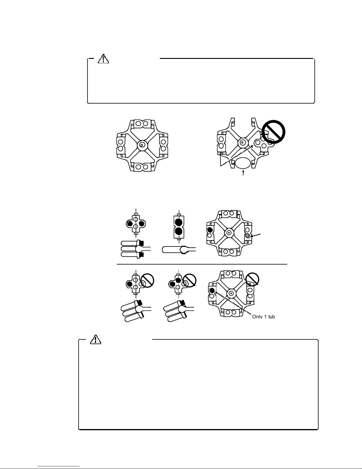
6-6
The same type buckets must be provided to every (4places) rotor yoke.
If not
p
ositively held in place, the rotor or centrifuge can be d amaged, thereb
y
cau sing accidents.
CAUTION
■
Distribute the tubes s
y
mmetrically about the center of the bucket.
・
A
pprop
riate balance is lost and violent vibratio ns can result if tubes are incorrectl
y
arranged. And, unexpected a ccidents can result from such violent vibrations.
・
The settlin
g
chambe r may be tilted since the tubes can't be maintained ho rizontal
durin
g
rotation.
・
When
y
ou don't have enough number of tubes, dummy tubes shall be used to
maintain s
y
mmetry of the both sides.
■
Kee
p
the load balanced symmetrically within 10 gram.
CAUTION
Correct Wron
g
Not all locations are provided
wi
th a bucket
.
Different t
yp
es of
buckets are used.
[2]
Settin
g
Buckets
[3] Tub e distr ibution method
Sect ion 6 Ro t or
Only
1
tube is hanging
Dumm
y
Put the dummy in to
kee
p
the l oad
balanced.
Correct
Wron
g
Page 56

6-7
Do n ot insert the cushion upside down or in a
slante d
p
osition, otherwise, the glass tube may be
dama
g
ed or you may not be able to remove it.
Cushion for 15ml Glass tube
Bucket
Cod e No.0 24-2 610
(
Bucket Code No.053-7340
)
Cod e No.0 24-1 400
(
Bucket Code No.053-4990
053-4910, 053-4900
053-4980
)
Cushion for 50ml Glass tube
Code No.024- 3190
Bucket
[4] Cushions / Ada
p
ter
When glass tubes are used, be sure to use the cushion to avoid damage.
Insert the cushion into the tube rack so that its concave side faces
upward.
If a
g
lass tube is damaged, replace the cushion.
If broken
p
ieces of the glass tube are contained in the cushion, the
g
lass tube will be broken again.
(1)
Cushion for 15ml and 50ml Glass tubes
How to
p
lace 15ml cushion
①
Place a cushion in the bucket with the
concave surface facin
g
upward.
②
Full
y
insert the cushion to the bottom of the
hole usin
g
a glass tube.
(
the edges of the cushion bend to prevent it
from comin
g
out.
)
How to place 50ml cushion
Place a cushion in the bucket with the
concave surface facin
g
upward.
Sect ion 6 Ro t or
Glass tube
Bucket
Cushion
Page 57

6-8
Code No.053- 5010
50 ml conical tube
Bucket
1
5
ml conical
tube
50ml conical tube
15ml conical tube
Adaptor
Code No.055- 6010
Code No.053- 5010
Bucket
Ada
p
tor
Code No.055- 6010
Cushion
6ml Glas s tube
[
Ex.]Carrier Code No.053-5030
Code No.024-1880
Cushion for carrier
Carrier
Code No.
Cushion
CodeNo.
053-5040
024-1880
053-5030
053-5850024-1890
(2)
Cushion for Carrier
The cushion for the carrier is shaped like a sheet.
The cushion is
p
laced on the bottom of the carrier.
(3)
Adapter for 15 ml / 50 ml conical tubes
When us ing the bucket (cod e No. 053-501 0) commonly
for both a 50 ml and a 15 ml conical tube, an o
p
tional
ada
p
ter (code No. 055-6010) must be us ed.
Sect ion 6 Ro t or
Adaptor
Code No.055- 6010
Page 58
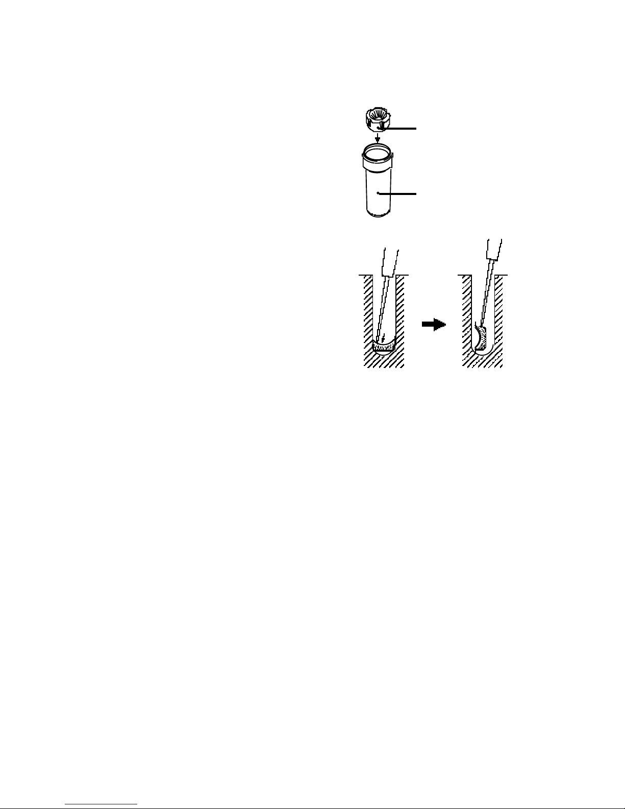
6-9
(4)
Cushion for 50 ml conical tube
The cushion (Code No.024-1480) is fitte d to
the bucke t
(
Co de No.053-501 0) and is
exclusivel
y
used for the 50ml conical tube
(
culture tube).
(5) How to remove cushion
①
Stick the cushion with an eyeleteer or a pai r
of
p
ointed tweezers.
②
Raise the cushion
perp
endicularly on the
bucket bottom.
③
Stick the side of the cushion to take it out.
Sect ion 6 Ro t or
Code No.053- 5010
Buck
et
Cushion for 50ml
Code No.024- 1480
Page 59

6-10
R
Maxi mum Speed (rpm
)
4,000
Maxi mum R C F
(
×g) *1
2,590
Maxi mum W
eight
(
k
g
)
1.9
Nomi-
na l
Capa-
cit
y
ml
Num-
ber
of
Tube
Mate-
rial
of
Tube
*2
Tube Sizes
Dia.×Le ngth
mm Form
*3
Tubes
Code No.
Allow-
ab le
Speed
rpm
R C F
×
g
Bucket
Code No.
Tube rack
/ Adaptor
Code No.
Cushion
Code No.
Maxi-
mum
Radi us
R
cm
Allow-
ab le
load
g
ra m
*4
516
GLPL12.5~ 1 3.5×
70~ 110
R
Becton,
Dickinson
Hemolyse tube
4,000
2,500
S13041
*5
S14033
-
14.0
350
520
GLPL11.8~ 1 2.8×
65~ 8 5
R RIA t ube 2,020S13009
-
11.3
720
GLPL11.5~ 1 2.5×
95~ 105
R
VENOJECT
Ⅱ
et c.
Hemolyse tube
2,400S13004
-
13.4
720
GLPL11.5~ 1 2.5×
65~ 105
2,500
S13041
*5
S1402914.0
154PL16.5×120.6C
Conica l tubes
FAL CO N etc.
2,560
S13150
*6
S1306014.3
1516PL
15.2~ 16.2×
80~ 110
R
-
2,500
S13041
*5
S1403014.0
158PL16.5×120.6C
Conica l tubes
FAL CO N etc.
2,560S13152
-
14.3
1516PL
16~ 1 7×
90~ 105
R
-
2,400S13012
-
13.4
254GL
23~ 24×
95~ 100
RS15025
2,400S13097S17925
-
13.4
25/ 304 GL
24~ 25.3×
75~ 105
2,500
S13041
*5
S14031
Cushio
n is
includ ed w it h
this t ub e rack.
14.0
504PL29.5×117C
Conica l tubes
FAL CO N etc.
2,590
S13150
*6*7
--
14.5
504GL
34~ 35×
95~ 100
R
S15050
2,400S13097S17950
-
13.4
504GL
34~ 35×
70~ 105
2,500
S13041
*5
S14032
Cushio
n is
in
cluded wit
h
this tube rack.
14.0
1004 GL
44.5~ 4 5.5×
95~ 105
RS151002,400S13097
-
S16051
Cushio
n is
in
cluded wit
h
this bucket.
13.4
*1
The Max. RCF is the calculation value of the Max. speed for the rotation radius of 14.5cm.
The value of the RCF that is indicated to the dis
play
is showing the value that cut the lower 2 digits.
Refer to page 3-12.
*2
GL : Pyrex Glass PL : Plastic
*3
C
:Conica
l
R
:Round t ype
*4
Allowable load per bucket.
This load includes the wei
g
ht of the sample, adaptor, tube rack, cushion, tube, cap, etc.
The wei
g
ht of bucket is not inc luded in the allowable load.
*5
Sealing cap No.S17140 is included with this Bucket.
*6
Sealing cap No.S17151 is included with this Bucket.
*7
When us ing the adapter (S13060), 4 tubes of 15ml conical tube can be used.
6-5.
RS-1004 Swinging Bucket Rotor
[1]
Specification
Sect ion 6 Ro t or
Page 60

6-11
The same type buckets must be provided to every (4places) rotor yoke.
If not
p
ositively held in place, the rotor or centrifuge can be d amaged, thereb
y
cau sing accidents.
CAUTION
■
Distribute the tubes symme trically about the center of the rotor.
Improper distribution will cause violent vibration resulting in damage to the
centrifu
ge,
or the rotor may come off.
■
Kee
p
the load balanced symmetrically within 10 gram.
CAUTION
Correct Wron
g
Not all locations are provided
with a bucket.
Different types of
buckets are used.
Only
1
tube is hanging
Dumm
y
Correct
Wron
g
Put the dummy in to
kee
p
the l oad
balanced
.
[2]
Setting Buckets
[3] Tub e distr ibution method
[4]
Standard accessories
(1)
Grease (SIGMA Parts No.70284)
・・・・・・・・・・・・・・
1Pc.
(2)
Rotor knob
・・・・・・・・・・・・・・・・・・・・・・・・・・・・・・・・・
1Pc.
Sect ion 6 Ro t or
Page 61

6-12
R1
A
RX
R2
Max i mum Speed (rpm
)
4,000
Max i mum R C F
(
×g) *1
1,790
Max i mum W
eight
(
k
g
)
1.6
Number
of
wells
Number
of
Plat e
Plat e
Material
*3
Plat e Si zes
mm
Allowable
Speed
rpm
R C F
×
g
Buckets
Radi us
R
1
cm
Allowable
load
g
ra m
*4
96
2~ 6
*2
PL
86×128×524,0001,790
Bucket is
incl
uded
with this
r
otor.
10345
962PL
*1
The Max. RCF i s the calculation value of the Max. s
p
eed for the rotation radius of 10 cm.
The value of the RCF that is indicated to the dis
play
is showing the value that cut the
lo wer 2 di
g
its. Refer to Page 3-12.
*2
The ma x imu m s
p
eed drops when the step number increases, although a micro plate is
p
oss ible to piling 3 steps. Refer to Page 6-15.
*3
PL : P lastic
*4
Allowable load
p
er bucket. This load includes the weight of the sample, plate,
ada
p
tor etc.
The wei
g
ht of bucket is not inc luded in the allowable load.
6-6.
RMP-23 Swinging Bucket Rotor
[1]
Specification
Calculating Centrifugal Force for RMP-23
Because of the size of the micro plate, the radius of rotation differs between the center and
the both ends with res
p
ect to the rotation axis,resulting in the difference in the centrifugal
force. The centrifu
g
al force of the place A (cm) Distant from the center of a bucket can be
calculated in accordance with the formula, where the rotation radius R shall be substituted
with the Rx to be obtained b
y
the formula mentioned below.
where, R
1
:
Radius rotation Minimum(cm
)
R
X
:
Actual rotation radiu s in a position which is A cm away from the center of the
bucket
.
Sect ion 6 Ro t or
RX(cm)= R
2
1
(cm)+A2(cm)
Page 62

6-13
The same type buckets must be provided to every (2 places) rotor yoke.
If not
p
ositively held in place, the rotor or centrifuge can be d amaged,
thereb
y
causing accidents.
CAUTION
If th e trunnion pin is loosened, contact
y
our local dealer for inspection .
Trunnion pin
CAUTION
Check the trunnion pin (4 places) is not loosened.
If the trunnion pin is loosened, the rotor or centrifuge can be damaged,
thereb
y
causing accidents.
Load the micro plate after detaching
the bucket
from the r
oto
r.
[2] Check the trunnion pin
[3]
Setting Buckets
Sect ion 6 Ro t or
Correct Wron
g
Page 63

6-14
■
Keep the load (of the sample) balanced.
If an a
pprop
riate balance is not prov ided, unexpected accidents can
result from a da ma
g
ed rotor or centrifuge.
■
Kee
p
the load balanced symmetrically within 5 gram.
CAUTION
Correct Wron
g
●
Sample
Use the same plates.
The wron
g
arrangement will cause i mbalance and resulting in damage
to rotor
,
bucket or the centrifuge.
CAUTION
[4] Distribution of samples
[5]
Setting plate
Sect ion 6 Ro t or
Page 64

6-15
■
When pile up the micro plate to each bucket in 3 steps, use i t aft er
the sufficient t est f or the stren
g
th of the plate is made.
The more the micro
p
lates are piled up, the easier the plate at the
lower
p
osition becomes damaged.
■
When dee
p
well plate is used, please ask the plate maker for the
allowable RCF of t he de e
p
well plates
.
■
Allowable weight of micro pl
ate and ce
ll culture pl
ate put
in the
bucket is 345
g
ram. If it exceeds 345 gram, rect ify reduced
maximum s
p
eed by the following formula.
If it is not used at the rectified s
p
eed, the rotor and the bucket will
be dama
ged,
causing the accident.
Allowable load (gram
)
Actual load (gram
)
Reduced maximum
=Maximum s
p
eed(rpm
)×
s
p
eed(rpm)
WARNING
[6]
Allowable weight of plate
[7] Standard accessories
Grease (SIGMA Parts No.70284
)
・・・・・・・・・・・・・・・・・・・・・・・・・・
1Pc.
Sect ion 6 Ro t or
Page 65

7-1
Max. speed
4
,
000 rpm
Max. RCF
2
,
610
×
g
Max. Capacit
y
400ml
Control s
y
stem
Invertor Micro
p
roc essor con trol, Speed, Centrifugal force, time,
acceleration / deceleration, 3 me mor
y
Acceleration/Deceleration
Ra
pid,
Slow, 4 ways of switching
Alarm dis
play
Lid open, Imbalance, Over speed, Function for detecting an
occurrence of electrical abnormalit
y
in speed sensor, invertor, Lid
rock, Motor
S
p
eed settin
g
Digital display, 200-4,000 rpm, in 100 rpm steps
S
p
eed indication
Di
g
ital display, 0-4,300 rpm, in 100 rpm steps
RCF settin
g
Digital display, in 100
×
g
steps
10-2,600 ×
g
(
The centrifu
g
al force differs by the rotation radius.
)
RCF indication
Di
g
ital display, in 100
×
g
steps
0-3,000
×
g
(
The centrifu
g
al force differs by the rotation radius.
)
Timer settin
g
range
From 1 second to 99 seconds
(
1 second ste
p)
1 minutes to 99 minute s(1 minutes step) HOLD
Settin
g
the Sound that
informs the end of the
o
p
eration
5 kind s + Sound none
Rated volta
g
e and Rated
current
100-115 V 50/60 Hz 3 A
200-240 V 50/60 Hz 1.3 A
Total heat
p
roduced
100-115 V 180 W 0.65 MJ/h
200-240 V 170 W 0.62 MJ/h
Dimensions
,
Weight
35
(W)
×
42
(D)
×
32
(H)
cm, 24 k
g
Safety regulation
IEC 61010-2-020, CLASS
Ⅰ
O
p
eration environment
Tem
p
erature : 10 to 40
℃
Atmos
p
heric pressure : 70 to 106 kpa (700 to 1,060 mbar
)
Humidity : 30 to 85%
Section 7
Specifications
7-1.
Centrifuge
7-2.
Standard Accessories
1. Instruction manual
・・・・・・・・・・・・・・・・・
1 Co
py
2. Power cable
・・・・・・・・・・・・・・・・・・・・・・・
1 Pc.
3. Rotor lockin
g
nut
・・・・・・・・・・・・・・・・・
1 Pc.
Page 66

8-1
Code No. Description Use , standard
Q'ty
014-0061 Micro switch VX-016-1A3 1
014-0071
Micro switch
V-102-1A5 1
029-0010 S
p
eed sensor 1
029-0009 CTL PC board Without ROM 1
066-0016
CPU ROM
1
014-0056 Invertor VFNC1S-1002P
,
For 10 0- 11 5V 1
014-0057 Invertor VFNC1S-2002PL, For 200-240V 1
017-0009
motor KC128 0.18kW
1
014-0059 Solenoid CKD DS-08A DC5V 1
014-4470 Circuit
p
rotector W28
×
Q
1A-8, For 100-115V 1
014-0065
Circuit
p
rotector
W28
×
Q
1A-5, For 200-240V 1
014-0062 Switchin
g
requireter CSJ010-05, For 100-115V 1
014-0063 Switchin
g
requireter CWA015-05, For 200-240V 1
014-0064
Power switch
AJ921001WW3 1
Section 8.
Parts List
8-1.
Recommended Spare Parts
Page 67

Index
Acceleratio n ・ Deceleration
1-2, 3-9
Reduced maximum speed
3-18
ACCEL
1-2, 3-9
Reminder alarm
3-16
Allowable load
3-18
Reverse of settin
g
order of
A
pp
earance
1-1
the Speed and the Timer
3-15
Autoclavin
g
Ⅴ
Rotation Radius
3-12
Calculatin
g
Centrifugal Force
3-18
sec
3-8
Centrif u
g
al force(×
g)
3-7
Sound that informs
3-14
Circuit Protector
4-6
the end of the o
p
eration
Cleanin
g
&Sterilization
4-3, 4-4
Speed
3-6
Contaminant Elimination
4-9, 4-10
STA RT
1-2, 3-2
Control Panel
1-1, 1-2
STO P
1-2, 3-2
DECEL
1-2, 3-9, 3-13
Tachometer
p
ort
1-1, 4-7
Timer
3-8
Greasin
g
4-5
Groundin
g
2-3
Usin
g
rotor
Ⅳ
HOLD
3-8
RMP-23
6-3, 6-11, 6-12, 6-13, 6-14
RS-1004
6-2, 6-9, 6-10
Indicators for the end RS-240
of the o
p
eration
3-17 6-1, 6-4, 6-5, 6-6, 6-7, 6-8, 6-9
Ins
p
ection
4-1 , 4- 2, 4-8
5-6, 5-7, 5-8
Life time of the rotors
Ⅳ
E0
5-1
Memor
y
1-2, 3-10
C1
5-2
min
3-8
C2
5-2
Movement of centrifu
g
e
2-1
C3
5-2
C4
5-2
O
p
ening and Closing the lid
3-4, 3-5
C5
5-2
O
p
eration
3-1 , 3- 2, 3-3
E1
5-3
Place of Installation
2-1
E2
5-3
Power Re
q
uirement
2-2
E3
5-3
E4
5-4
E6
5-4
E7
5-4
Error Indicators
O
H
I
P
S
T
Troubleshootin
g
G
D
C
U
Rotor
Alarm Indicators
R
L
M
A
Page 68

Page 69

 Loading...