

Kubota B01 Series, 1KB01PR, 1KB01ST Owner's Manual

1 of 29
INSTALLATION & OWNER
’S MANUAL
Kubota B01
Premium Cab p/n: 1KB01PR
Standard Cab p/n: 1KB01ST
Fits Tractor Models: B2301 and B2601
(*=Not including accessories)
Premium Cab Shown with Optional Front and Rear LED Work Lights
Available Options:
1. Front LED Work Lights (P/N: 9LEDW4)
2. Rear LED Work Lights (P/N: 9LEDW3)
3. Strobe Light (P/N: 9LEDS2)
4. Dome light (P/N 9LEDD14)
5. Heater (P/N: 9PH20S62)
6. Switch Panel (P/N: 9PSF1)
7. Side View Mirrors (P/N: 9PM5)
9. Rear View Mirror (P/N: 9PM3)
8. Rear Wiper (P/N: 9PWK85F)
Note: Front wiper (P/N: 9PWK110) is supplied with premium cab kit only.
Approximate Installation Time *
Experienced Dealer Technician – 3.5 Hours
Average Dealer Technician – 4.5 Hours
Do-It-Yourself – 5.5 Hours
Approximate Product Specifications
Floorboard to Roof Height: 62 inches
Weight: 290 lbs. (Premium), 221 lbs. (Standard)
Cab Width: 41 inches
Rev. D, 07/12/2019
p/n: IM-1KB01PR
The contents of this envelope are the property of the owner. Leave with the owner when installation is complete.
While this cab kit was designed to fit on the vehicle(s) listed above, manufacturing tolerances and vehicle
assembly may affect cab fitment. It is the responsibility of the cab installer to check all vehicle pedals and
levers for full functionality and, as required, adjust the cab fitment to prevent any interference of the cab
components with the travel of pedals or levers.

2 of 29
TABLE OF CONTENTS
WARNINGS, TIPS, & REQUIRED TOOLS ...................................................... 3
CAB INSTALLATION .................................................................................. 4-20
CAB FEATURES & OPERATION ............................................................. 21-22
CARE AND MAINTENANCE ......................................................................... 22
SWITCHED POWER WIRING HARNESS SCHEMATIC ............................... 23
SERVICE PARTS .................................................................................... 24-27
OPTIONAL ACCESSORIES ......................................................................... 28
BOLT TORQUE SPECIFICATIONS .............................................................. 29
3 of 29
Curtis cabs feature an assembly of parts designed for your vehicle which require adjustment
and alignment of components to accommodate vehicle variations and provide proper weather
protection. For accurate installation, proper operation, and years of satisfaction, please read
and understand the installation and owner’s manual fully prior to installing the cab.
From all of us at Curtis, we thank you for choosing our product.
HELPFUL HINTS:
• Refer to parts diagram found in the service parts section of this manual to help
identify parts during the assembly process.
• To assist with the cab installation, leave all fasteners loose for later adjustment
unless otherwise specified.
• Read and understand all instructions before beginning.
• Apply a silicone sealant to seal any minor gaps that may occur due to vehicle
variations.
• Use caution to avoid damaging the factory installed threaded inserts or weld
nuts. Begin the thread engagement by hand to avoid or correct potential cross
threading.
• Make sure the areas where the supplied self-adhesive hook Velcro will be
applied are clean and dry and at room temperature for best adhesion.
• Before installing parts with factory installed rubber, make sure the rubber is fully
installed onto the parts for proper fit and sealing.
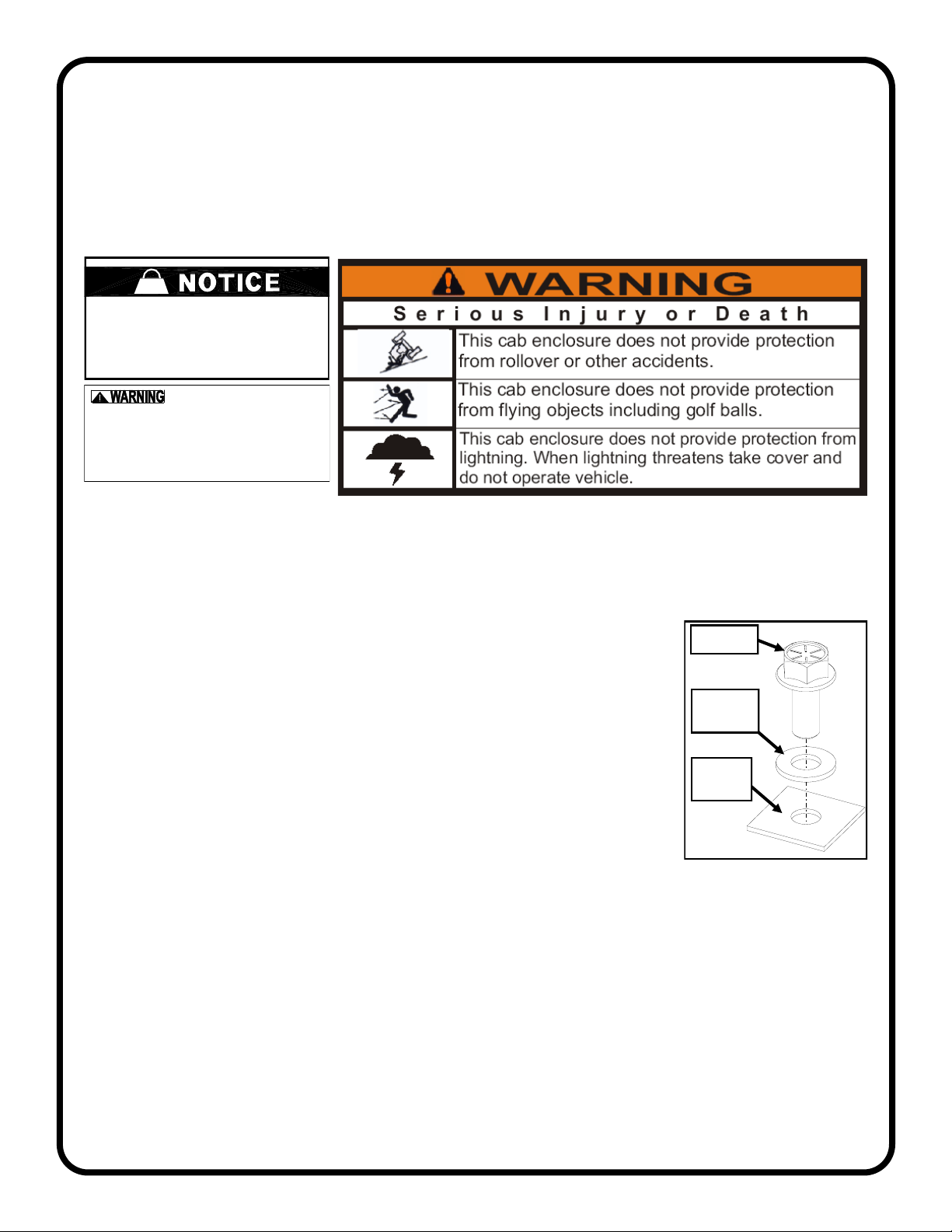
• Plastic washers have been supplied to provide a weather seal under the heads
of some exterior bolts. The plastic washer should be installed under each bolt
head directly against the outside cab surface. Care should be taken not to over
tighten the fasteners and damage the plastic washer.
driver and passenger.
Curtis accessory weights are listed in product
add additional weight to the base vehicle. All
Curtis Cabs, blades and general accessories
ADDED
WEIGHT
brochures. Deduct the accessory's total weight
from the vehicle's rated capacity and never
exceed the vehicle's rated capacity including
Exposure to Carbon Monoxide
can Cause illness, serious injury or
death. Never operate vehicle if suspicio us of Carbon Monox-
ide. Inspect exhaust system for le aks monthly. Leaks can
result from loose connections, c orrosion, cracks or other
damage to the exhaust manifold. If leaks are found, repair or
replace exhaust system. Do not us e vehicle until repair or
• Set of Standard and Metric Sockets (3/8” Drive)
• 3/8” Drive Ratchet and Long Drive Extension
• Set of Standard and Metric Open End Wrenches
• Set of Standard and Metric Allen Wrenches
• #2 and #3 Phillips Head Screwdrivers
• Torque Wrench
• Rubber Mallet or Plastic Dead Blow Hammer
• Center Punch
• Awl
• Test light or Volt Meter
• Drill/Driver
• 3/8” and 7/32” Drill Bits
• #2 and #3 Phillips Head Bit
• Utility Knife
• Pair of Scissors
• Shears
• Grease
• C-Clamps
• Silicone Sealant
WARNINGS, TIPS, & REQUIRED TOOLS
TOOLS REQUIRED:
GENERAL INFORMATION BEFORE YOU START
fastener
plastic
washer
cab
surface
CAB INSTALLATION
4 of 29
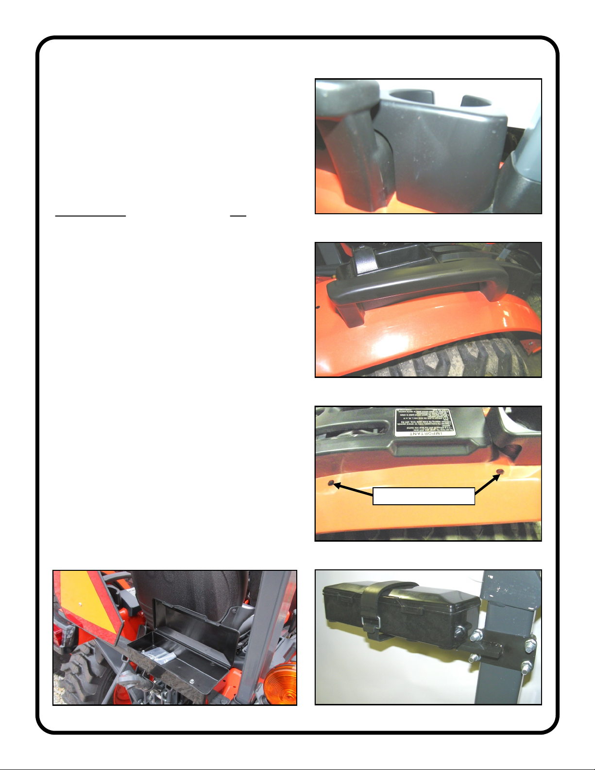
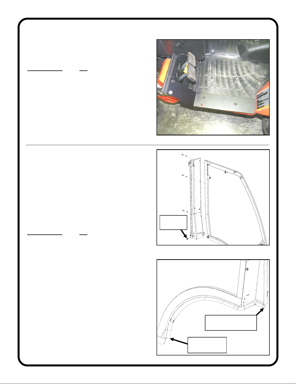
STEP 1: (VEHICLE PREP)
1.1 Per figure 1.1, remove and discard the cup holder
found on the top left fender.
1.2 Per figure 1.2, remove and discard the left and right
fender handles.
1.3 Install the hardware listed below into the exposed
handle mounting holes found on the vehicle’s left and
right fender. See fig 1.3.
Hardware Used Qty
5/16-18 X 3/4 Flange Head Cap Screw 4
5/16 Plastic Washer 4
5/16-18 Flange Nut 4
1.4 For TLB Models Only:
• Per figure 1.4, remove tool box and mount found on
the right side of the ROPS (Rollover Protective
Structure) and discard.
1.5 For non-TLB Models Only:
• Per figure 1.5, remove tool box, SMV (slow moving
vehicle) sign and SMV mounting bracket and
hardware found on the vehicle rear cross brace and
discard.
Fig. 1.1 (cup holder - left fender)
Fig. 1.4 (tool box and mount)
Fig. 1.2 (fender handle - right)
Fig. 1.5 (tool box, SMV sign and mount - rear cross brace)
Fig. 1.3 (left fender)
install hardware here
CAB INSTALLATION
5 of 29
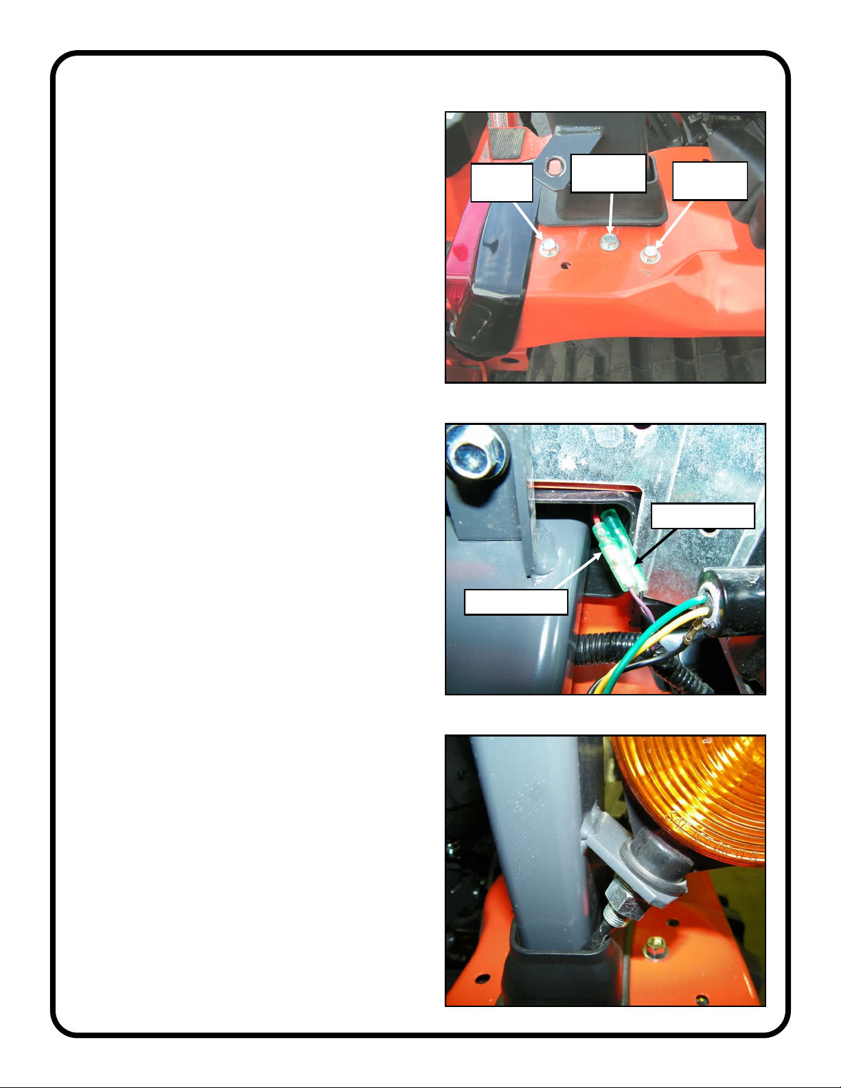
STEP 1: (VEHICLE PREP cont’d.)
1.6 Per figure 1.6, remove and discard the middle piece
of hardware found on the fenders near the ROPS. If the
vehicle includes the hardware closest to the seat,
remove and discard.
1.7 Per figures 1.7a and 17.b, disconnect all signal light
wires and remove the (2) signal lights from the vehicle
and set aside for reuse.
Fig. 1.7a (signal light wires - under the left fender)
Fig. 1.7b (signal light mount - right)
disconnect wire
disconnect wire
Fig. 1.6 (fender hardware - right)
discard this
hardware
discard this
hardware
leave
installed
CAB INSTALLATION
6 of 29
Fig. 1.10 (right side view of ROPS)
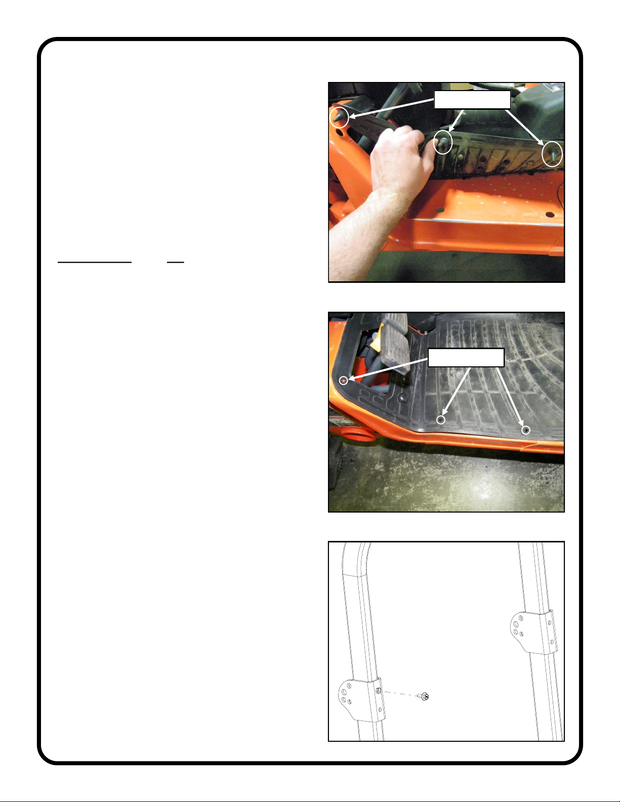
STEP 1: (VEHICLE PREP cont’d.)
1.8 Peel up both the right and left sides of the rubber
mat. Using a utility knife, remove the (3) outer tabs on
both sides of the mat for a total of (6) tabs. See fig 1.8.
Re-install both sides of the mat in place.
1.9 Using an awl, feel for the (6) outer holes of the
rubber mat and punch holes thru the mat. Drill (6) holes
(3/8” diameter) thru the rubber mat. See fig 1.9.
1.10 Remove the ROPS adjustment knob found on the
right side of the ROPS. Replace with metric hardware
provided. See fig. 1.10.
Hardware Used Qty
M10 X 25 FHCS 1
Fig. 1.9 (rubber mat with holes)
Fig. 1.8 (underside of floor mat - left floorboard)
3/8” holes
remove tabs
CAB INSTALLATION
7 of 29
STEP 2: (SEAL KIT)
Seal Kit is included on Premium Cabs only.
Note: the flattest side of the flex brush should face
down for best fit and finish. Bristles to butt up against
each other with NO gaps or overlap unless otherwise
stated. When drilling, do not press down too hard.
Denting or puckering may occur if too aggressive.
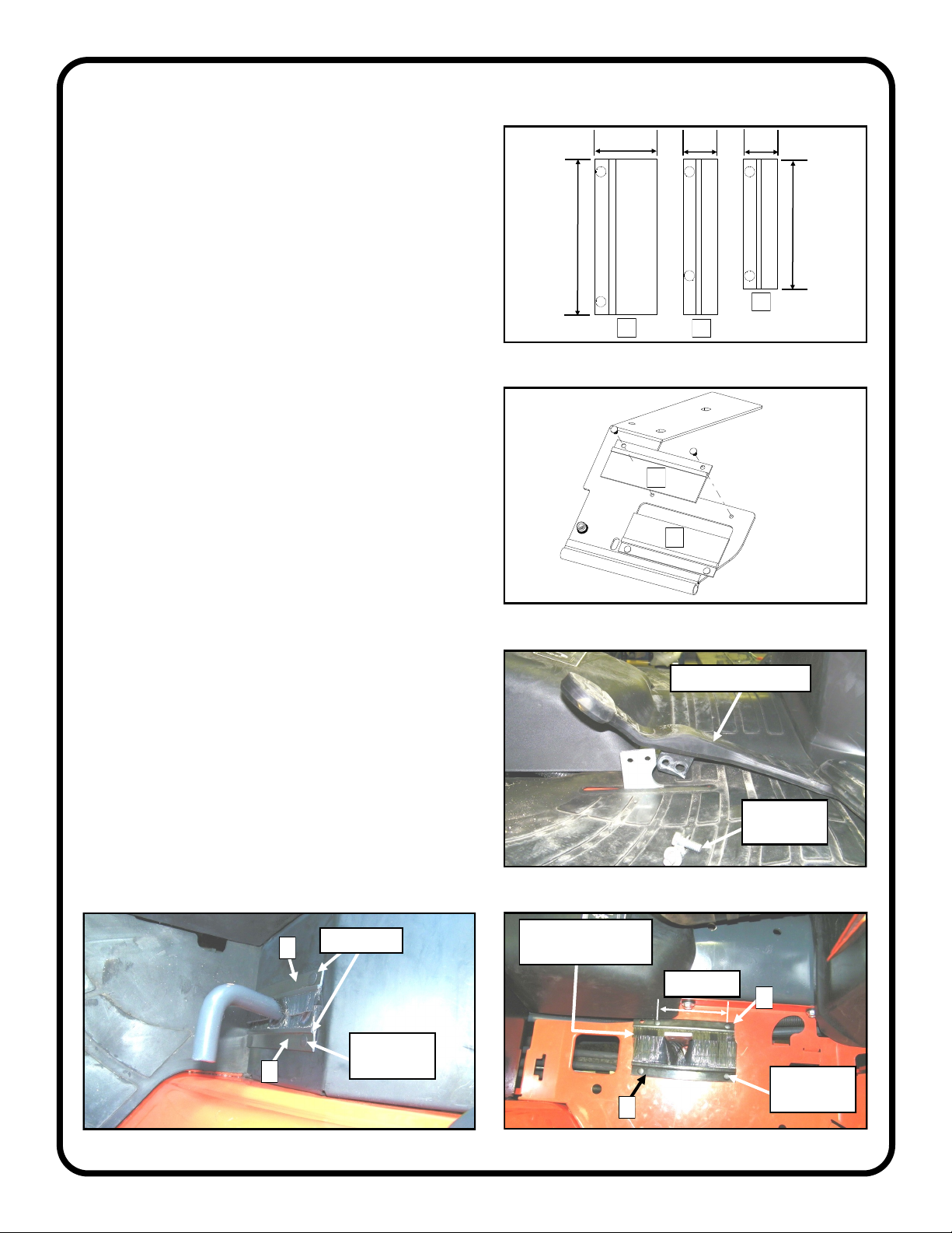
2.1 Install (2) 6” long flex brushes (item “A” in fig 2.1a)
to the underside of the left floorboard mount, using (4)
plastic tree clips. See figures 2.1a and 2.1b. Note: the
(2) brushes on the floorboard mount do overlap.
2.2 Remove the hardware from forward/rev pedal, set
aside the pedal and hardware. See fig. 2.2. Peel back
rubber mat.
2.3 Per figures 2.1a and 2.3, install flex brushes as
shown on the right floorboard (one “A” brush and one
“B” brush). Using the hole pattern in the flex brush as a
guide, drill two holes per side (7/32” diameter) thru the
sheet metal floorboard. Note: It is recommended that a
spare piece of metal is placed behind where you are
drilling to ensure no damage is done to the vehicle.
2.4 Per figures 2.1a and 2.4, install flex brushes as
shown around the differential lock lever found on the
left fender (two “C” brushes). Using the hole pattern in
the flex brush as a guide, drill two holes per side (7/32”
diameter) thru the sheet metal fender.
2.5 Re-install the right side of the rubber mat in place
and remount the forward/rev pedal.
Fig. 2.1b (underside of left floorboard mount)
Fig. 2.2 (forward/rev pedal - right floorboard)
Fig. 2.3 (flex brush installation - forward/rev pedal)
Fig. 2.4 (flex brush installation - differential lock pedal)
drill 2 holes
per brush
5” brushes
drill 2 holes
per brush
4” spacing
bristles to butt up
against each other
A
Fig. 2.1a (3 flex brush sizes included in seal kit)
A
A
A
B
C
C
mounting
hardware
forward/rev pedal
B
C
6”
5”
2.4”
1.3” 1.3”
CAB INSTALLATION
8 of 29
STEP 3: (FLOOROARD MOUNTS)
3.1 Using the hardware listed below, install the left and
right floorboard mounts per fig. 3.1.
Hardware Used Qty
5/16-18 X 1 FHCS 6
5/16-18 Flange Nut 6
Fig. 3.1 (left floorboard mount installation)
Fig. 4.2 (rear leg to sideframe - left)
Fig. 4.3 (1” round bulb rubber installed - left)
STEP 4: (SIDEFRAMES/REAR LEGS)
For Premium Cab only.
If installing a standard cab, proceed to step 5 on the
next page.
4.1 For ease of handling, temporarily remove the doors
from the sideframes. Make sure to also remove the (4)
hinge washers and set aside for reuse.
4.2 Using hardware listed below, bolt the left rear leg to
the left sideframe and then right rear leg to the right
sideframe. See fig. 4.2.
Hardware Used Qty
5/16-18 X 3/4 FHCS 8
5/16 Plastic Washer 6
4.3 Starting at the floorboard of the left sideframe,
install the 1” round rubber provided onto the sideframe,
continue up the sheetmetal edge of the sideframe and
then onto the rear leg. Cut the rubber flush with the
inside rear flange of the rear leg. See fig. 4.3.
Note: Use a rubber mallet or plastic dead blow hammer
as needed to secure the rubber onto the sideframe and
rear leg.
start 1” round bulb
rubber here
cut rubber flush with
inside edge of rear leg
no washer
required
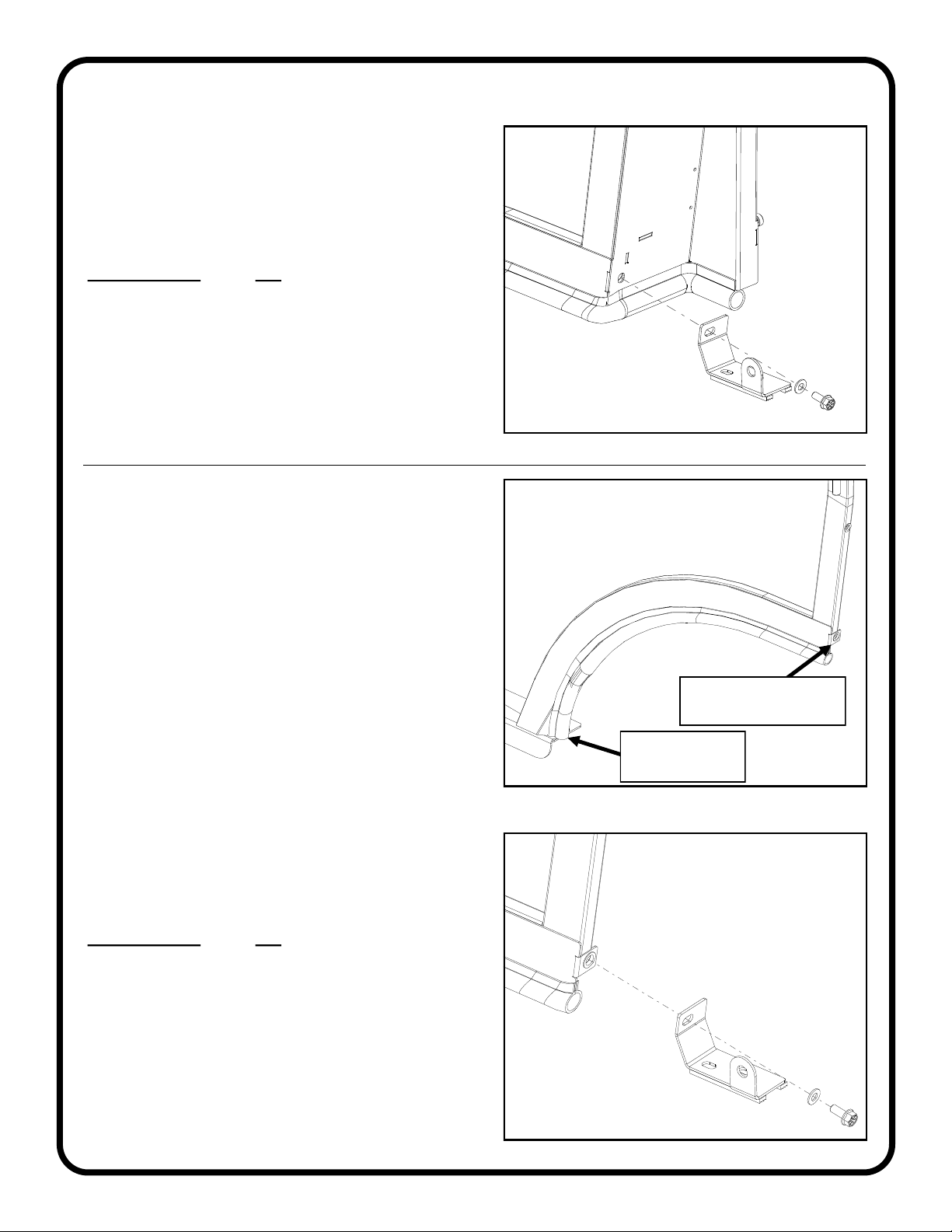
CAB INSTALLATION
9 of 29
STEP 4: (SIDEFRAMES/REAR LEGS
cont’d.)
4.4 Using hardware listed below, bolt the left fender
bracket to the left sideframe/rear leg. Making sure to
fully tighten hardware down. See fig. 4.4. Repeat the
process for the right fender bracket.
Hardware Used Qty
5/16-18 X 3/4 FHCS 2
5/16 Plastic Washer 2
Fig. 4.4 (fender bracket installation - left)
Fig. 5.3 (fender bracket onto sideframe tab - left)
STEP 5: SIDEFRAMES
For Standard Cab only.
If installing a premium cab, proceed to step 6 on the
next page.
5.1 For ease of handling, temporarily remove the doors
from the sideframes. Make sure to also remove the (4)
hinge washers and set aside for reuse.
5.2 Starting at the floorboard of the left sideframe,
install the 1” round rubber provided onto the sideframe,
continue up the sheetmetal edge of the sideframe. Cut
the rubber flush with the inside rear flange of the fender
contour. See fig. 5.2.
Note: Use a rubber mallet or plastic dead blow hammer
as needed to secure the rubber onto the sideframe and
rear leg.
5.3 Using hardware listed below, bolt the left fender
bracket to the left sideframe tab. Making sure to fully
tighten hardware down. See fig. 5.3. Repeat the
process for the right fender bracket.
Hardware Used Qty
5/16-18 X 3/4 FHCS 2
5/16 Plastic Washer 2
Fig. 5.2 (1” round bulb rubber installed - left)
start 1” round bulb
rubber here
cut rubber flush with
back edge of sideframe
 Loading...