

Page 1

KUBOTA
Toro Part No. 01090SL
REPAIRMATE
Workshop Manual
05 Series
Diesel Engine
Reprinted from KUBOTA Workshop Manual, 05 Series Diesel Engine (English language only)
E KUBOTA Corporation 1996
Page 2

Page 3
TO
THE READER
This Workshop Manual has been prepared to provide
information
SERIES. It
each section.
•
Mechanism
Information on the construction and function are included
part should
servicing.
• Disassembling
Under the heading
of servicing specifications and periodic inspection items. For each engine section, there
are
"Checking
cover procedures, precautions, factory specification and
All
engines.
The mark
All
the latest production information available at the time of publication.
The right is reserved to make changes
Due to covering many models of this manual,
been specified as one model.
on
the mechanism, service and maintenance of
is
divided into two parts,
be
understood before proceeding with troubleshooting, disassembling and
and Servicing
"General"
and Adjustment",
the engines that have been manufactures since January of
[E]
in
the WSM refers to the said clean engine.
information,
illustrations
"Mechanism"
section comes general precautions, troubleshooting, lists
"Disassembling
and specifications contained
in
and
"Disassembling
and Assembling", and
allowable limits.
all
information at any time without notice.
illustration
serv1cmg
KUBOTA
for each engine section. This
1994
in
this manual are based
or picture being used have not
personnel with
Diesel Engines
and
Servicing"
"Servicing"
are clean exhaust
05
for
which
on
©
KUBOTA Corporation
1996
May
'96
01640Z00040
Page 4
SAFETY
~h¥m"~~.IW.MW~.IW~~
INSTRUCTIONS
05
SERIES WSM, 01640
~
~
This
~
the engine
~
It
is essential that you read the instructions and safety regulations before you attempt
~
use this unit.
symbol,
itself
the
industry's
to
warn
of
the
A
SAFETY FIRST
"Safety Alert Symbol",
possibility
of
personal injury. Read these instructions
is
used
throughout
~.IWH~UHH'~~~~UHH'H//H"A
A
DANGER :Indicates
or
serious injury.
A
WARNING:Indicates
or
serious injury.
A
CAUTION :Indicates a
or
moderate injury.
• IMPORTANT :Indicates
followed.
an imminently hazardous situation which,
a
potentially
potentially
that
equipment
hazardous situation which,
hazardous situation which,
or
property damage
if
could result
if
this
manual and decals on
carefully.
to
if
not
avoided, will result in death
not
avoided, could result in death
not
avoided, may result in minor
if
instructions are
repair
or
not
~
~
~
~
~
OOOOOF00010
:Gives
helpful
information.
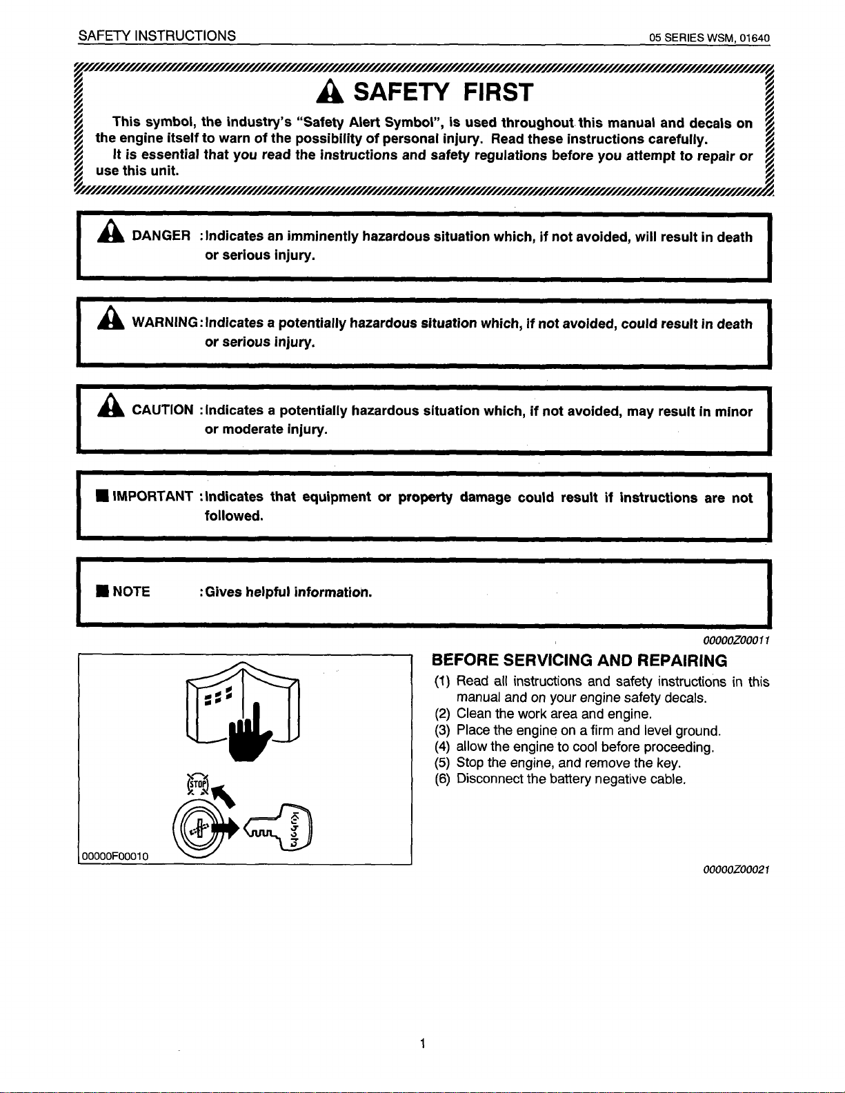
BEFORE SERVICING
(1)
Read
all
instructions and safety instructions in this
manual and
(2)
Clean
(3)
Place
(4)
allow
(5)
Stop
the engine, and remove the key.
(6)
Disconnect the battery negative
on
your engine safety
the work area and engine.
the engine on a firm and
the engine to
cool before proceeding.
AND
REPAIRING
decals.
level
cable.
I
OOOOOZ00011
ground.
OOOOOZ00021
Page 5
05
SERIES WSM,
01640
SAFETY
INSTRUCTIONS
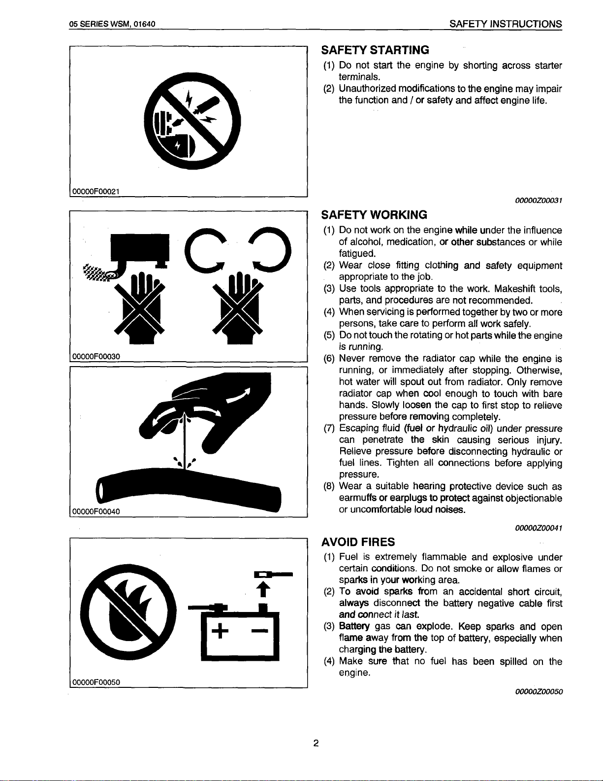
SAFETY STARTING
(1)
Do not start the engine by shorting across starter
terminals.
(2)
Unauthorized modifications to the engine may impair
the function and
I
or safety and affect engine life.
OOOOOF00021
OOOOOF00030
OOOOOZ00031
SAFETY WORKING
(1)
Do
not work
of alcohol, medication, or other substances or while
fatigued.
(2)
Wear
appropriate to the job.
(3)
Use tools appropriate to the work. Makeshift tools,
parts, and procedures are not recommended.
(4)
When servicing is performed together by two or more
persons, take care to perform
(5)
Do
not touch the rotating or hot parts while the engine
is
running.
(6)
Never remove the radiator cap while the engine is
running, or immediately after stopping. Otherwise,
hot water
radiator cap when cool enough to touch with bare
hands. Slowly loosen the cap to first stop to relieve
pressure before removing completely.
(7)
Escaping fluid (fuel or hydraulic oil) under pressure
can penetrate the skin causing serious injury.
Relieve pressure before disconnecting hydraulic or
fuel lines. Tighten
pressure.
(8)
Wear a suitable hearing protective device such
earmuffs or earplugs to protect against objectionable
or uncomfortable loud noises.
on
the engine while under the influence
close fitting clothing and safety equipment
all
work safely.
will spout out from radiator.
all connections before applying
Only
remove
as
OOOOOFOOOSO
+
I
-
AVOID FIRES
(1)
Fuel
is
extremely flammable and explosive under
certain conditions.
sparks in your working area.
(2)
To avoid sparks from
always disconnect the battery negative cable first
and connect
(3)
Battery gas can explode. Keep sparks and open
flame away from the top of battery, especially when
charging the battery.
(4)
Make sure that no fuel has been spilled
engine.
2
it
last.
Do
not smoke or allow flames or
an
accidental short circuit,
OOOOOZ00041
on
the
OOOOOZ00050
Page 6
SAFETY
INSTRUCTIONS
05 SERIES WSM, 01640
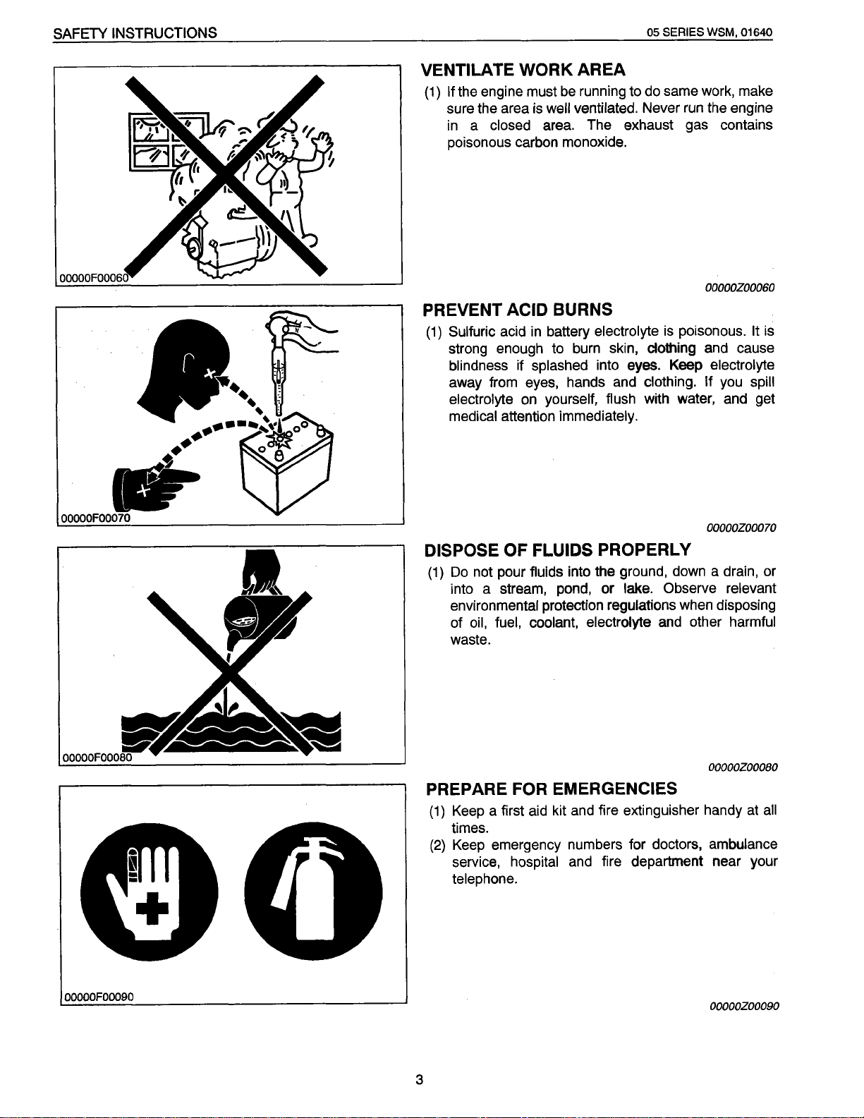
VENTILATE
the engine must
If
{1)
sure the area
a
in
poisonous carbon monoxide.
PREVENT
Sulfuric
{1)
strong enough to
blindness
away from eyes, hands and
electrolyte
medical
WORK AREA
be
well
is
closed area. The exhaust gas contains
ACID BURNS
battery
in
acid
splashed
if
yourself, flush
on
attention immediately.
same
running to
ventilated.
electrolyte
burn
into eyes. Keep
do
run
Never
poisonous.
is
skin, clothing and cause
clothing. If
with water, and get
make
work,
engine
the
OOOOOZ00060
is
It
electrolyte
spill
you
OOOOOZ00070
DISPOSE OF
not pour
Do
(1)
into a stream, pond, or lake. Observe relevant
environmental
oil,
of
waste.
PREPARE FOR
a first
Keep
(1)
times.
Keep
(2)
service,
telephone.
FLUIDS PROPERLY
into the ground,
fluids
protection
fuel, coolant, electrolyte
regulations
down
when
and other harmful
EMERGENCIES
fire extinguisher handy
and
kit
aid
emergency numbers for doctors,
fire department near your
hospital
and
a drain, or
OOOOOZOOOBO
ambulance
disposing
all
at
OOOOOF00090
OOOOOZ00090
3
Page 7
05 SERIES WSM, 01640
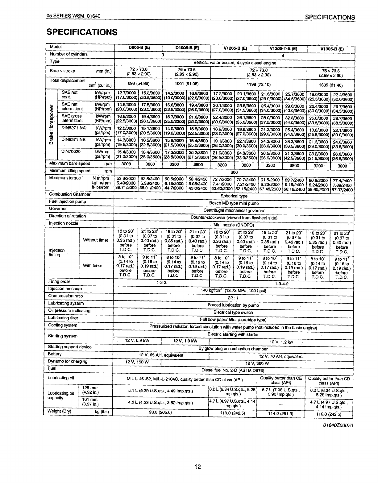
SPECIFICATIONS
SPECIFICATIONS
Model
Number
of
cylinders
Type
Bore
x
stroke
Total displacement
SAE
net
cont.
SAE
net kW/rpm
intermittent (HP/rpm)
~
0
SAEgross
a.
(I)
intermittent (HP/rpm)
~
0
DIN6271-NA kW/rpm
J:
(I)
-a
DIN6271-NB kW/rpm
m
DIN70020
Maximum
Minimum idling speed rpm
Maximum torque
Combustion
Fuel
Governor
Direction
Injection nozzle
bare
injection
of
Chamber
pump
rotation
mm{in.)
3
cm
kW/rpm
(HP/rpm)
kW/rpm
(ps/rpm)
(ps/rpm)
kW/rpm
(ps/rpm)
speed
N·m/rpm 53.8/2000 52.8/2400
kgf·m/rpm 5.49/2000
ft-lbs/rpm
Without
Injection
timing
I
Firing order
Injection pressure
Compression ratio
Lubricating system
Oil pressure indicating
Lubricating filter
Cooling
system
Starting
system
Starting
support device
Battery
Dynamo
Fuel
Lubricating
Lubricating
capacity
Weight
(Dry)
tor
charging
oil
oil
With
timer
125
mm
(4.92in.)
101
mm
(3.97in.)
kg (lbs)
0905·8
{E)
72
X
73.6
{2.83
X
2.90)
(cu. in.)
rpm
timer
898 (54.86)
12.713000 15.3/3600 14.2J3000 16.8/3600 17.2/3000 20.1/3600 21.6/3000
(17.0/3000) (20.5/3600) (19.013000) (22.&/3600) (23.0/3000) (27.0/3600)
14.9/3000 17.5/3600 16.813000 19.4/3600 20.1/3000 23.5/3600 25.4/3000 29.8/3600 22.4/3000
(20.0/3000)
16.8/3000 19.4/3600 16.713000
(22.5/3000) (26.0/3600) (25.013000)
12.5/3000 15.1/3600
(17.0/3000) (20.5/3600) (19.0/3000) (22.5/3000)
14.3/3000 16.5/3600 15.813000 18.4/3600 19.1/3000 22.1/3600 24.3/3000 28.3/3600 21.3/3000 24.6/3600
(19.5/3000) (22.5/3600)
15.4/3000 18.4/3600
(21
3200
39.71/2000 38.91/2400
18
(0.31
0.35 rad.)
before before
T.D.C.
a to
(0.14 to
0.17
before before
T.D.C.
(23.5/3600)
.0/3000) (25.0/3600) (23.5/3000) (27.5/3600)
3800
5.38/2400 6.18/2000 5.95/2400 7.41/2000 7.21/2400
to
20'
21
to
to
10'
rad.)
12
V,
12V,
MIL-L-46152,
5.1
4.0
23'
(0.37to
0.40 rad.)
T.D.C.
Stoll'
(0.16
to
0.19
rad.)
T.D.C. T.D.C.
1-2-3
Pressurized radiator,
0.9
kW
12
V,
65
AH,
150W
MIL-L-2104C,
L (5.39 U.S.qts.,
L (4.23 U.S.qts.,
93.0 (205.0)
01005-8
{E)
3
Vertical,
water-cooled, 4-cycle diesel engine
76
X
73.6 72
(2.99
X
2.90)
1001 (61.08)
{22.513000)
14.013000
(21.5,/3000)
17.313000
60.6/2000
44.712000
18
(0.31
0.35
before before
T.D.C. T.D.C.
8
(0.1410 (0.16
0.17 rad.)
before before before before before
equivalent
4.49 lmp.qts.)
3.52lmp.qts.)
(26.0/3600) (27.0/3000) (31.5/3600) (34.0/3000) (40.0/3600) (30.0/3000)
21.613600
(29.0/3600)
16.5/3600 16.9/3000 19.9/3600 21.3/3000 25.4/3600 18.8/3000 22.1/3600
(25.0/3600) (26.0/3000)
20.2/3600 21.0/3000 24.3/3600 26.513000 31.3/3600 23.2/3000 26.8/3600
3200
to
rad.)
to
12V,
3800
58.4/2400
43.0/2400
Counter-clockwise (viewed from flywheel side)
20'
21
to
(0.37
0.40 rad.)
10'
9to
0.19 rad.)
T.D.C.
forced
1.0kW
22.4/3000 26.1/3600
{30.0/3000) (35.0/3600) (37.5/3000)
(23.0/3000)
(28.5/3000)
72.7/2000 70.7/2400
53.60/2000 52.15/2400 67.46/2000 66.18/2400 59.60/2000
Bosch
Centrifugal mechanical governor
Mini nozzle (DNOPD)
to
23'
18
to
(0.31
0.35
before before
T.D.C. T.D.C.
11'
8to
to
(0.14
0.17 rad.)
T.D.C. T.D.C.
140
kgf/cm"
Forced lubrication by
Electrical type switch
Full
flow
paper
circulation with water
Electric starting with starter
.
By
glow plug in combustion
I
Diesel
fuel
quality better than
CD
6.0
L (6.34
4.7 L (4.97
V1205-B
{E)
V1205-
T
-B
4
X
73.6 76
(2.83
X
2.90)
1198
(73.10)
(29.0/3000) (34.5/3600) (25.5/3000)
28.0/3000 32.813600 25.0/3000
(27
.0/3600)
(29.0/3000) (34.5/3600) (25.5/3000)
(30.0/3600)
(33.0/3600) (36.0/3000) (42.5/3600) (31.5/3000)
3200
600
Spherical
type
MD
type mini pump
to
20'
21
to
(0.37
rad.)
0.40
10'
9to
to
(0.16
0.19 rad.)
(13.73 MPa, 1991
22:
1
(33.0/3000) (38.5/3600) (29.0/3000) (33.5/3600)
3800
to
rad.)
11'
3200 3800
91.5/2000
9.33{2000
18
23'
(0.31
to
0.35
before before before before
T.D.C.
8to
(0.14
to
0.17 rad.)
T.D.C.
psi)
25.7/3600
(44.0/3600)
89.7/2400 80.8/2000 77.4/2400
9.15/2400 8:24/2000
to
20'
21
to
(0.37to
rad.)
0.40
T.D.C. T.D.C. T.D.C.
10'
9to11'
to
(0.16to
0.19 rad.)
before
T.D.C.
1-3-4-2
pump
filter
(caltridge type)
pump
(not
included
in
the
12V,1.2kw
chamber
12
V,
70
AH, equivalent
12V,
360W
No. 2-D
(ASTM
D975)
class
U.S.qts.,
lmp.qts.)
U.S.qts., 4.14
lmp.qts.)
110.0
(242.5)
(API)
Quality better than CE
class (API)
5.28 6.7 L
5.90
114.0
(7.08 U.S.qts.,
lmp.qts.)
-
(251.3)
{E)
19.0/3000 22.4/3600
(33.5/3000) (38.5/3600)
3200
to23'
18
to20'
(0.31
rad.)
0.35
8to
(0.14to
0.17 rad.)
before
T.D.C.
basic engine)
Quality better than
6.0
5.28 lmp.qts.)
4.7
4.141mp.qts.)
110.0
V1305-B
(2.99
1335
to
rad.)
10'
class
L (6.34
L (4.97
{E)
X
73.6
X
2.90)
(81.46)
(30.0/3600)
25.7/3600
(34.5/3600)
28.7/3600
(30.0/3600)
{36.5/3600)
3800
7.89/2400
57.07/2400
21
to
(0.37to
0.40 rad.)
9to
(0.16to
0.19
rad.)
before
T.D.C.
(API)
U.S.qts.,
U.S.qts.,
(242.5)
23'
11'
CD
12
01640Z00070
Page 8
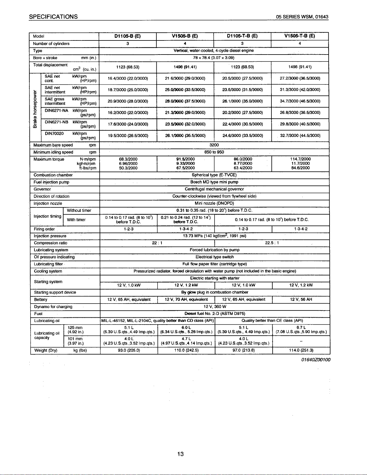
SPECIFICATIONS
05 SERIES WSM, 01643
Model 01105-B (E)
Number
of
cylinders
Type
Bore x stroke
Total displacement
net
SAE
cont. (HP/rpm)
net
SAE
interrrittent
lii
3:
0
SAE gross kW/rpm
0..
Q)
intermittent (HP/rpm)
~
0
DIN6271-NA kW/rpm
.c
Q)
.><
DIN6271-NB kW/rpm
!!!
CD
DIN70020 kW/rpm
Maximum bare speed rpm
Minimum idling speed rpm
Maximum torque N·m/rpm 68.3/2000
Combustion chamber
Fuel
injection pump
Governor Centrifugal mechanical governor
of
Direction
Injection nozzle
Injection timing
Firing order
Injection pressure
Compression ratio
Lubricating system Forced lubrication by pump
Oil pressure indicating Electrical type switch
Lubricating filter
Cooling system
Starting system
Starting support device
Battery
Dynamo for charging
Fuel
Lubricating
Lubricating
capacity
Weight (Dry) kg (lbs) 93.0 (205.0)
rotation
oil
oil
mm(in.)
cm3 (cu. in.)
kW/rpm
kW/rpm
(HP/rpm)
(ps/rpm)
(ps/rpm)
(ps/rpm)
kgf·m/rpm 6.96/2000
ft-lbs/rpm 50.3/2000
Without timer
With timer
125mm
(4.92 in.) (5.39 U.S.qts.,4.491mp.qts.)
101
mm
(3.97 in.) (4.23 U.S.qts.,3.52 lmp.qts.) (4.97 U.S.qts. ,4.14 lmp.qts.) (4.23 U.S.qts.,3.52 lmp.qts.)
16.4/3000 (22.0/3000)
18.7/3000 (25.0/3000)
20.9/3000 (28.0/3000)
16.2/3000 (22.0/3000)
17.6/3000 (24.0/3000)
19.5/3000 (26.5/3000)
0.14to
12
MIL-L-46152, MIL-L-2104C, quality better
3
1123 (68.53)
0.17 rad.
(8to
before T.D.C.
1-2-3
12
V,
V, 65 AH, equivalent
5.1
4.0L
10•)
Pressurized radiator, forced circulation
1.0 kW
L
22:
V1505-B (E)
4
Vertical, water-cooled, 4-cycle diesel engine
78 X 78.4 (3.07 X 3.09)
1498 (91.41) 1123 (68.53)
21
6/3000
(29.0/3000) 20.5/3000 (27.5/3000)
25.013000 (33.5/3000) 23.5/3000 (31.5/3000)
28.013000 (37.5/3000) 26.1/3000 (35.0/3000) 34.7/3000 (46.5/3000)
21.3/3000 (29.0/3000) 20.2/3000 (27.5/3000) 26.8/3000 (36.5/3000)
23.!W300() (32.0/3000) 22.4/3000 (30.5/3000) 29.8/3000 (40.5/3000)
26.1/3000 (35.5/3000) 24.6/3000 (33.5/3000) 32.7/3000 (44.5/3000)
850to950
91.5/2000 86.0/2000 114.7/2000
9.33/2000 8.77/2000 11.7/2000
67.5/2000 63.4/2000 84.6/2000
Spherical type (E-TVCE)
MD
Bosch
Counter-<:lockwise (viewed from flywheel side)
Mini nozzle (DNOPD)
to
0.35 rad. (18 to 20•) before T.D.C.
0.31
0.21 to 0.24 rad. (12 to 14.)
before T.D.C.
1-3-4-2
13.73 MPa (140 kgf/cm
1
Full flow paper filter (cartridge type)
with water pump (not included in the basic engine)
Electric starting with starter
12V,
1.2kW
By
glow plug in combustion chamber
12 V, 70 AH, equivalent
12V,
Diesel fuel
!han
(6.34 U.S.qiS., 5.281mp.qts.) (5.39 U.S.qts., 4.49 lmp.qts.) (7.08 U.S.qts.,5.90 lmp.qts.)
6.0L
4.7 L 4.0 L
110.0 (242.5) 97.0 (213.8) 114.0 (251.3)
No
CD
class (API) Quality better than CE class (API)
01105-
3200
type mini pump
0.14 to 0.17 rad. (8 to 10•) before T.D.C.
1-2-3
2
,
1991 psi)
12V,1.0kW
12 V, 65 AH, equivalent
360W
.. 2-D (ASTM D975)
5.1
T-B (E)
3 4
22.5:
L 6.7 L
V1505-T-B (E)
1498 (91.41)
27.2/3000 (36.5/3000)
31.3/3000 (42.0/3000)
1-3-4-2
1
12V,
12V,
1.2
kW
56 AH
-
01640Z00100
13
Page 9
'
MECHANISM
CONTENTS
• FEATURE .........................................................................................................
• ENGINE BODY ................................................................................................ M-3
[1]
CYLINDER BLOCK .................................................................................... M-3
[2]
CYLINDER HEAD ...................................................................................... M-3
[3]
CRANKSHAFT ............................................................................................ M-5
[4] PISTON AND PISTON RINGS ................................................................ M-5
[5] CONNECTING ROD .................................................................................. M-7
[6] ROCKER ARM ........................................................................................... M-7
[7] CAMSHAFT ................................................................................................ M-7
[8]
FUEL CAMSHAFT ..................................................................................... M-9
[9]
FLYWHEEL.. ............................................................................................... M-9
• LUBRICATING SYSTEM ...............................................................................
[1]
GENERAL. ................................................................................................
[2]
OIL PUMP ................................................................................................ M-13
[3]
RELIEF VALVE ........................................................................................ M-13
[4]
OIL FILTER CARTRIDGE. ...................................................................... M-15
[5]
OIL PRESSURE SWITCH ...................................................................... M-15
• COOLING SYSTEM ....................................................................................... M-17
[1]
GENERAL. ................................................................................................ M-17
[2]
WATER PUMP ......................................................................................... M-17
[3]
THERMOSTAT ......................................................................................... M-19
[4]
RADIATOR (not included
[5] RADIATOR CAP ...................................................................................... M-21
in
the basic engine) ......................................... M-19
M-1
M-11
M-11
D INTAKE I EXHAUST SYSTEM ...................................................................... M-23
[1] AIR CLEANER (not included
[2]
MUFFLER (not included
• FUEL SYSTEM .............................................................................................. M-25
[1]
GENERAL. ................................................................................................ M-25
[2]
INJECTION PUMP ................................................................................... M-25
(1)
Pump Element... .................................................................................. M-27
(2)
Delivery Valve ..................................................................................... M-27
(3)
Dumping Valve .................................................................................... M-29
(4)
Injection Control .................................................................................. M-29
[3]
INJECTION NOZZLE ...............................................................................
[4]
FUEL FILTER (not included
[5] GOVERNOR ............................................................................................. M-33
[6]
AUTOMATIC ADVANCE TIMER (not included
B ELECTRICAL SYSTEM .................................................................................
[1]
CHARGING SYSTEM ..............................................................................
(1)
Alternator .............................................................................................
(2)
IC Regulator ........................................................................................
• TURBO CHARGER SYSTEM ....................................................................... M-43
(1)
Mechanism .......................................................................................... M-45
(2)
Turbine ................................................................................................ M-47
(3)
Compressor ......................................................................................... M-47
(4)
Bearing ................................................................................................ M-49
(5)
Seals (Piston Rings) ...........................................................................
in
the basic engine) .................................. M-23
in
the basic engine) .......................................... M-23
in
the basic model) .....................................
in
the basic model) ...... M-37
M-31
M-31
M-41
M-41
M-41
M-41
M-51
Page 10
DIESEL ENGINE
II
FEATURE
05
SERIES
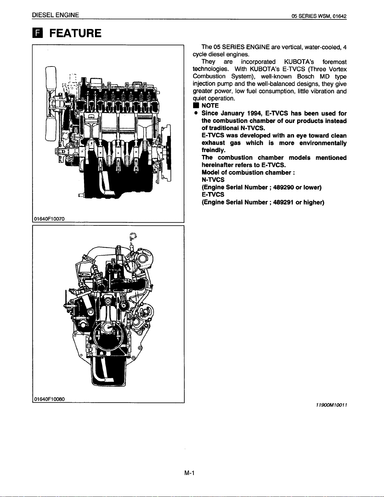
The
05 SERIES ENGINE are
cycle diesel
They are incorporated KUBOTA's foremost
technologies.
Combustion System},
injection pump and the
greater power, low fuel
quiet operation .
• NOTE
•
Since January 1994,
engines.
With KUBOTA's
well-known Bosch MD type
well-balanced
consumption,
the combustion chamber
of
traditional
E-
TVCS was developed
N-
TVCS.
exhaust gas which
vertical, water-cooled,
E-TVCS
designs, they give
little
E-
TVCS has been used
of
our
products instead
with an eye toward
is
more environmentally
WSM,
(Three
vibration and
freindly.
The combustion chamber
hereinafter refers
Model
of
combustion chamber :
to
E-
TVCS.
models
mentioned
N-TVCS
(Engine Serial
Number ;
489290
or
lower)
E-TVCS
(Engine
Serial
Number ;
489291
or
higher)
01642
4
Vortex
for
clean
01640F10070
01640F10080
11900M10011
M-1
Page 11
DIESEL ENGINE
0 ENGINE BODY
[1]
CYLINDER BLOCK
SERIES WSM, 01640
05
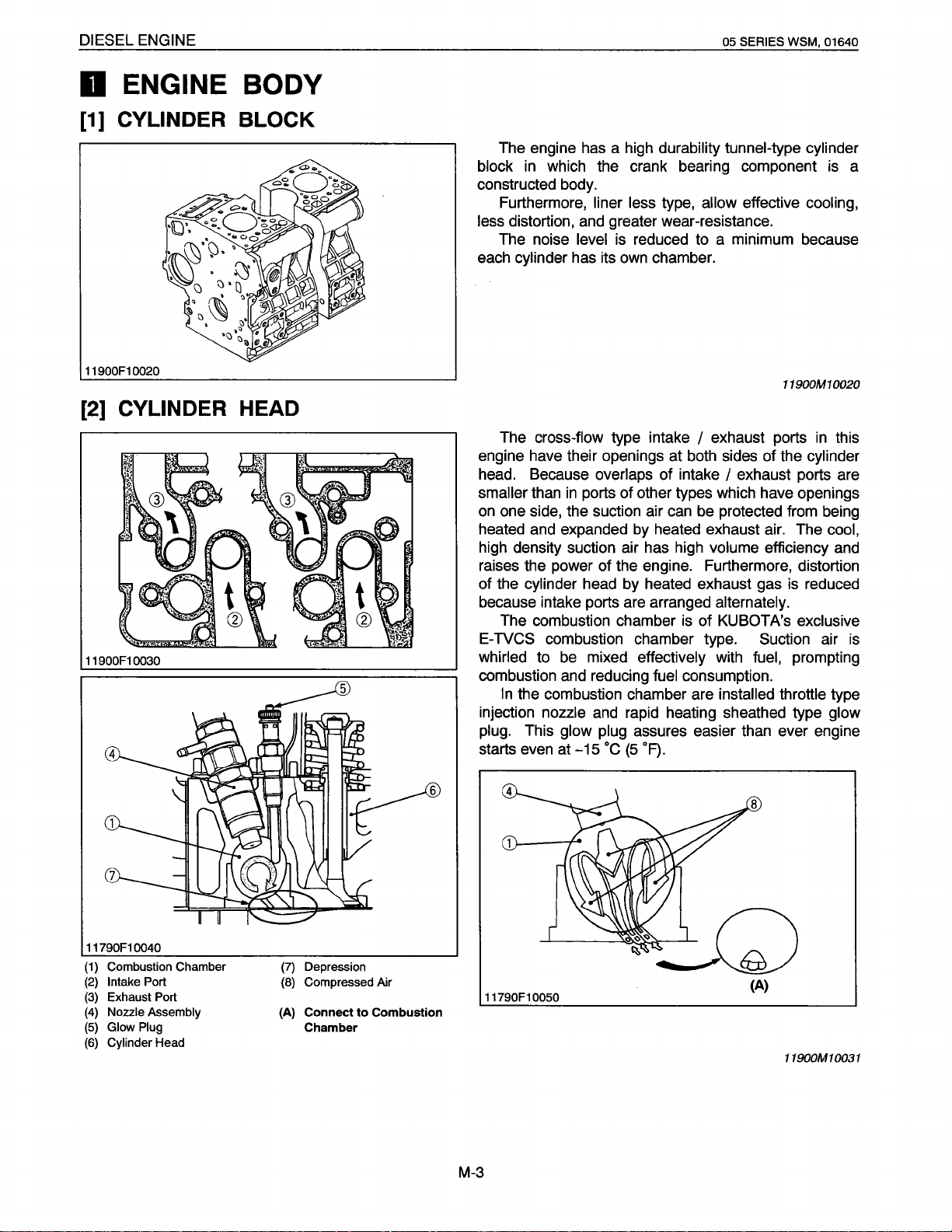
The engine has a high durability tunnel-type cylinder
block
in
which the crank bearing component is a
constructed body.
Furthermore, liner less type, allow effective cooling,
less distortion, and greater wear-resistance.
The noise level is reduced to a minimum because
each cylinder has its own chamber.
11900F10020
[2]
CYLINDER HEAD
11900F1 0030
11900M1 0020
The cross-flow type intake I exhaust ports in this
engine have their openings at both sides of the cylinder
head. Because overlaps
smaller than
in
ports of other types which have openings
of
intake I exhaust ports are
on one side, the suction air can be protected from being
heated and expanded by heated exhaust air. The cool,
high density suction air has high volume efficiency and
raises the power of the engine. Furthermore, distortion
of the cylinder head by heated exhaust gas is reduced
because intake ports are arranged alternately.
The combustion chamber is
of
KUBOTA's exclusive
E-TVCS combustion chamber type. Suction air is
whirled to be mixed effectively with fuel, prompting
combustion and reducing fuel consumption.
In
the combustion chamber are installed throttle type
injection nozzle and rapid heating sheathed type glow
plug. This glow plug assures easier than ever engine
starts even at
-15
·c
(5
·F).
11790F1 0040
(1)
Combustion Chamber (7) Depression
(2)
Intake Port
(3)
Exhaust Port
(4)
Nozzle Assembly {A)
(5)
Glow Plug
(6)
Cylinder Head
(8)
Compressed Air
Connect
Chamber
to
Combustion
11790F10050
M-3
(A)
11900M10031
Page 12
DIESEL ENGINE
[3]
CRANKSHAFT
11790F10060
[4]
PISTON AND PISTON RINGS
05 SERIES WSM, 01642
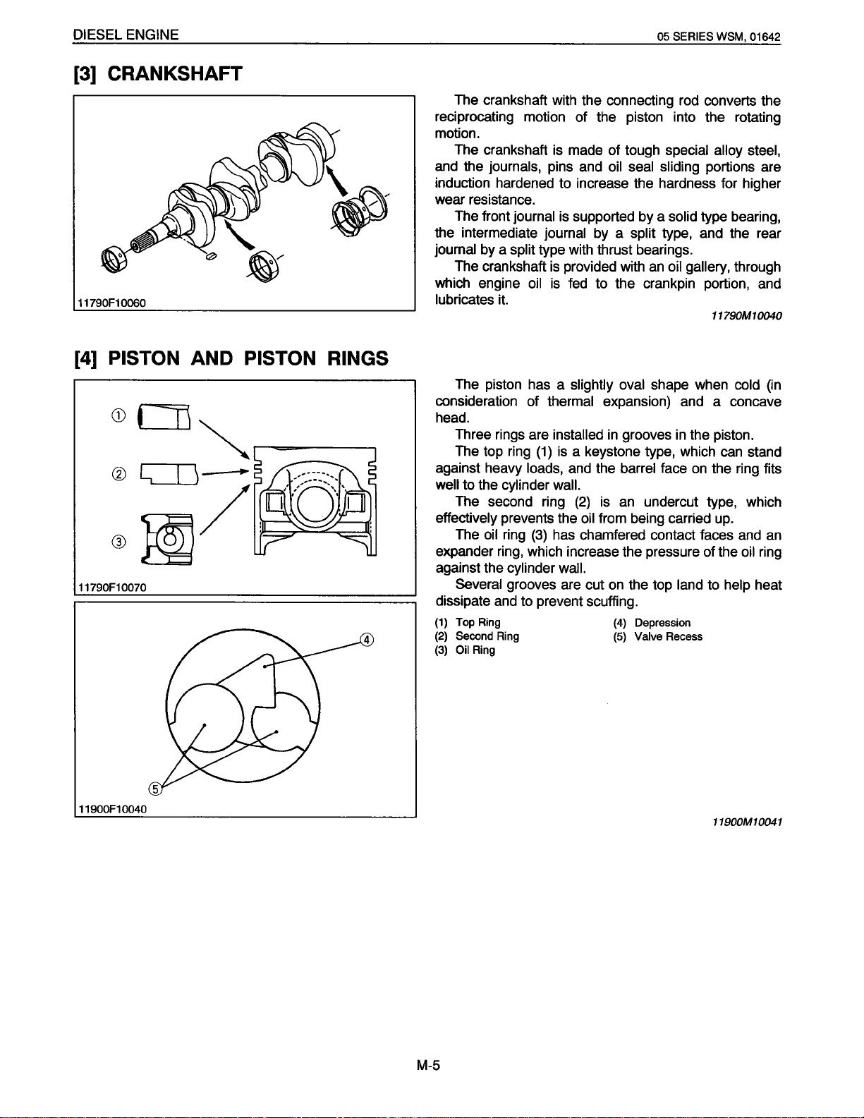
The crankshaft with the connecting rod converts the
reciprocating motion of the piston into the rotating
motion.
The crankshaft is made of tough special alloy steel,
and the journals, pins and oil seal sliding portions are
induction hardened to increase the hardness for higher
wear resistance.
The front journal is supported by a solid type bearing,
the intermediate journal by a split type, and the rear
journal by a split type with thrust bearings.
The crankshaft is provided with an oil gallery, through
oil
is
fed
which engine
lubricates
it.
to the crankpin portion, and
11790M10040
11790F10070
The piston has a slightly oval shape when cold
(in
consideration of thermal expansion) and a concave
head.
in
Three rings are installed
(1)
The top ring
is a keystone type, which can stand
grooves
against heavy loads, and the barrel face
in
the piston.
on
the ring fits
well to the cylinder wall.
The second ring
effectively prevents the oil from being carried
The oil ring
{3)
(2)
is
an
undercut type, which
up.
has chamfered contact faces and
an
expander ring, which increase the pressure of the oil ring
against the cylinder wall.
on
Several grooves are cut
dissipate
(1)
(2)
(3)
and
Top
Ring
Second Ring
Oil Ring
to prevent scuffing.
the top land to help heat
(4)
Depression
(5)
Valve Recess
11900F10040
11900M10041
M-5
Page 13
DIESEL ENGINE
[5]
CONNECTING ROD
05 SERIES WSM, 01640
11790F1 0090
[6]
ROCKER
11900F10060
[7]
CAMSHAFT
ARM
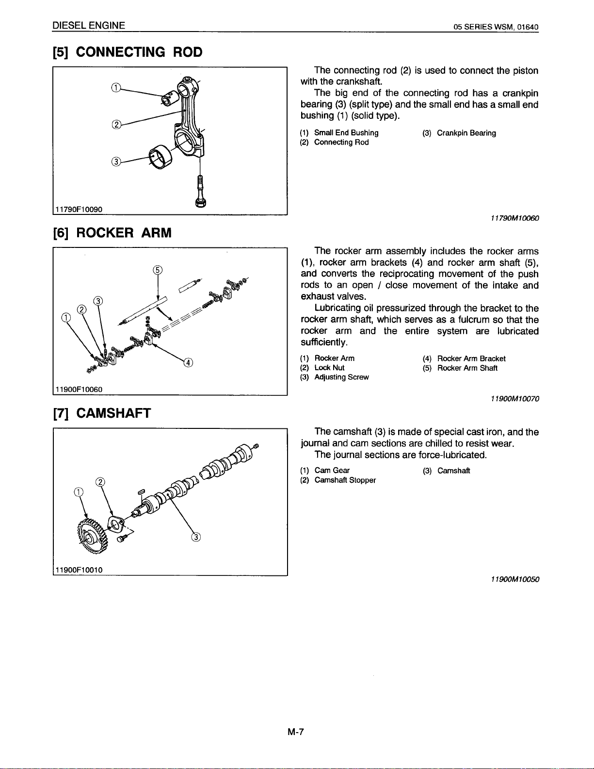
The connecting rod
(2)
is
used to connect the piston
with the crankshaft.
The big end of the connecting rod has a crankpin
bearing
bushing
(1)
(2)
(1
(3)
(split
type) and the small
(1)
(solid
type).
Small
End
Connecting Rod
Bushing
(3)
Crankpin Bearing
The rocker arm assembly includes
),
rocker arm brackets
(4)
and rocker arm shaft
end has a
small
11790M 10060
the rocker arms
end
(5),
and converts the reciprocating movement of the push
rods to
exhaust
rocker arm shaft, which serves as a
rocker arm and the entire system are
an
open
valves.
Lubricating
I
close
movement
oil
pressurized through the bracket to the
of
the intake and
fulcrum
so that the
lubricated
sufficiently.
(1)
Rocker Arm
(2)
Lock Nut
(3)
Adjusting Screw
(4)
Rocker Arm Bracket
(5)
Rocker Arm Shaft
11900M10070
11900F10010
The camshaft
journal
(1)
(2)
and cam sections are
The
journal
Cam Gear
Camshaft Stopper
(3)
is made of
sections are
special
chilled
cast iron, and the
to resist wear.
force-lubricated.
(3)
Camshaft
11900M10050
M-7
Page 14
DIESEL ENGINE
[8]
FUEL CAMSHAFT
05 SERIES WSM, 01640
01640F10090
[9]
FLYWHEEL
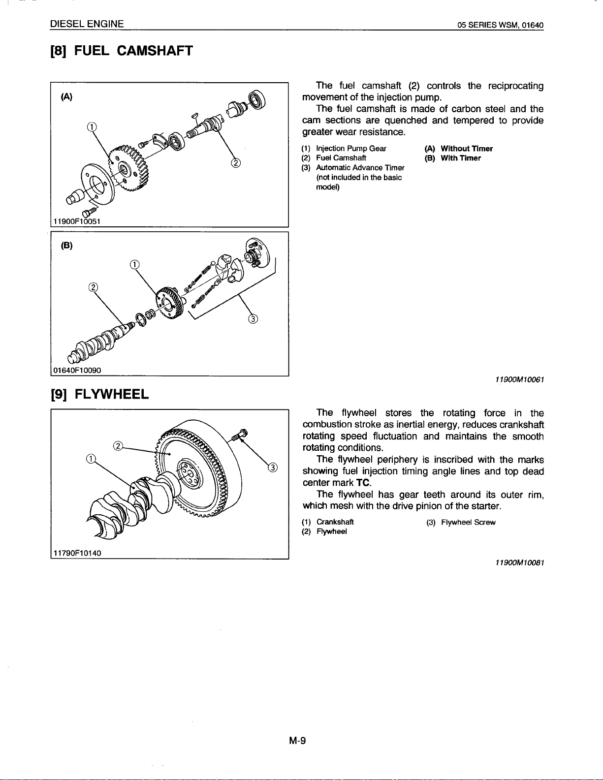
The fuel camshaft
of
movement
the injection pump.
The fuel camshaft is made
(2)
controls the reciprocating
of
carbon steel and the
cam sections are quenched and tempered to provide
greater wear resistance.
(1)
Injection Pump Gear
(2)
Fuel Camshaft
(3)
Automatic Advance Timer
(not included in the basic
model)
(A) Without Timer
(B) With Timer
11900M10061
11790F10140
The flywheel stores the rotating force
in
the
combustion stroke as inertial energy, reduces crankshaft
rotating speed fluctuation and maintains the smooth
rotating conditions.
is
The flywheel periphery
inscribed with the marks
showing fuel injection timing angle lines and top dead
center mark TC.
The flywheel has gear teeth around its outer rim,
which mesh with the drive pinion
(1) Crankshaft
(2) Aywheel
of
the starter.
(3) Flywheel Screw
11900M10081
M-9
Page 15
DIESEL ENGINE
fJ
LUBRICATING SYSTEM
[1]
GENERAL
05 SERIES WSM, 01640
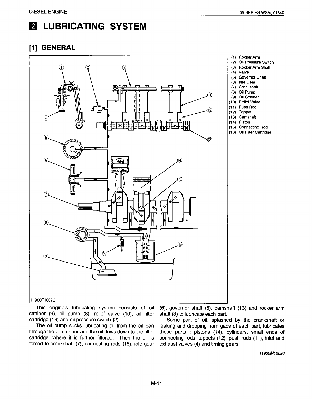
Rocker Arm
(1)
Oil
Pressure Switch
(2)
Rocker Arm
(3)
Valve
(4)
(5)
Governor
Idle
(6)
Crankshaft
(7)
Oil
(8)
Oil Strainer
(9)
Relief Valve
(10)
Push Rod
(11)
(12) Tappet
Camshaft
(13)
Piston
(14)
Connecting Rod
(15)
Oil Filter
(16)
Shaft
Gear
Pump
Cartridge
Shaft
11900F10070
This engine's lubricating
strainer
cartridge
through the
cartridge, where it
forced
The
(9),
(16)
oil
pump sucks
oil
to
crankshaft
oil
pump
and
oil
strainer
pressure switch
is
(7),
system consists of
(8),
relief valve
lubricating
and
the
oil
flows
further
filtered.
connecting rods
(2).
oil
from the
down
(1
0),
oil
to
the filter
Then the
(15),
idle
oil
filter
pan
oil
gear
oil
(6),
governor shaft
shaft
(3)
to
lubricate each part.
Some
leaking
part of
and
these parts : pistons
is
connecting
exhaust
rods,
valves
M-11
(5),
camshaft
oil, splashed
(13)
and
by the crankshaft or
dropping from gaps of each part,
(14),
cylinders, small
tappets
(4)
(12),
and
timing gears.
push rods
(11),
rocker
arm
lubricates
ends of
inlet
and
11900M10090
Page 16
DIESEL ENGINE
[2]
OIL
11900F10080
PUMP
(A)
(B)
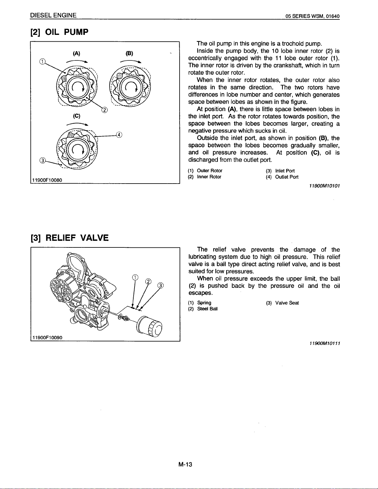
The
oil
pump
Inside
eccentrically
the pump body, the 1
engaged with the
The inner rotor
in
this engine
is
driven
05 SERIES
is
a trochoid pump.
0 lobe
11
lobe
by
the crankshaft, which
WSM,
inner rotor
outer rotor
01640
(2}
in
turn
is
(1).
rotate the outer rotor.
When the inner rotor rotates, the outer rotor
rotates
differences
space between
the
in
the same direction. The two rotors have
in
lobe
number and center, which generates
lobes
as
At position (A), there
inlet
port.
As
the rotor rotates towards position, the
shown
is
little
in
the figure.
space between
also
lobes
in
space between the lobes becomes larger, creating a
negative pressure which sucks
Outside the
space between the
and
oil
pressure increases. At position
inlet
port, as shown
lobes becomes
in
oil.
in
position (8), the
gradually smaller,
(C),
oil
discharged from the outlet port.
(1)
Outer
(2)
Inner
Rotor
Rotor
(3)
(4)
Inlet Port
Outlet
Port
11900M10101
is
[3]
RELIEF
11900F10090
VALVE
The relief valve
lubricating system due
valve
is a
ball
type direct acting relief valve,
suited for
(2)
low
pressures.
When
oil
pressure exceeds the upper limit, the
is pushed back
escapes.
(1)
Spring
(2)
Steel Ball
prevents the damage of the
to
high
oil
by
the pressure
(3)
pressure. This
oil
Valve
Seat
and
relief
and
is
best
the
11900M10111
ball
oil
M-13
Page 17
DIESEL ENGINE
[4]
OIL FILTER CARTRIDGE
05 SERIES WSM, 01640
11900F10100
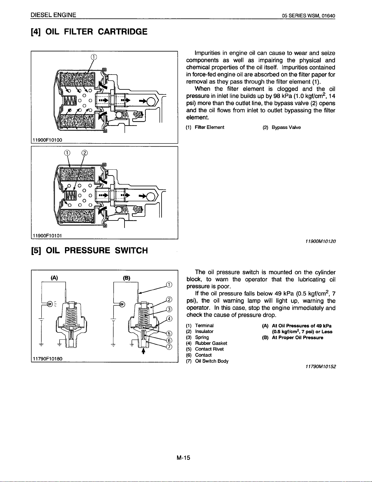
Impurities
components
chemical properties of the
in
force-fed engine
removal
When the filter element
pressure
in
engine
as
as
they pass through the filter element
in
inlet line builds
oil
well
as
oil
are absorbed
can
cause to wear
impairing the physical
oil
itself. Impurities contained
on
the filter paper for
is
clogged
up
by
98
kPa (1.0 kgf/cm
and
psi) more than the outlet line, the bypass valve
and
the
oil
flows from inlet to outlet bypassing the filter
element.
(1)
Filter Element
(2)
Bypass Valve
and
(1).
(2)
seize
and
the
2
,
opens
oil
14
01
11900F1
[5]
l
11790F10180
01
OIL PRESSURE SWITCH
{A)
l
{B)
The
oil
block,
to
pressure
If the
psi), the
operator.
pressure switch
warn the operator that the lubricating
is
poor.
oil
pressure falls below 49 kPa (0.5 kgf/cm
oil
warning lamp will light
In
this case, stop the engine immediately
is
mounted
check the cause of pressure drop.
Terminal
(1)
(2) Insulator
Spring
(3)
(4) Rubber Gasket
(5)
Contact Rivet
(6) Contact
(7)
Oil Switch Body
(A)
(B)
At
(0.5
At
Oil
Pressures
kgf/cm
Proper
11900M10120
on
the cylinder
up,
warning the
2
7
psi)
,
Oil
Pressure
11790M10152
of
49 kPa
or
2
and
Less
oil
,
7
M-15
Page 18
DIESEL ENGINE
II
COOLING SYSTEM
[1]
GENERAL
05
SERIES WSM, 01640
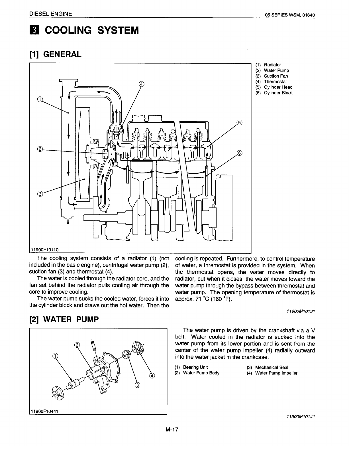
Radiator
(1)
Water Pump
(2)
Suction
(3)
Thermostat
(4)
Cylinder Head
(5)
Cylinder Block
(6}
Fan
11900F10110
The cooling
included
in
suction fan
The water is
fan set behind the radiator
core to improve
system consists of a radiator
the basic engine), centrifugal
(3)
and thermostat
cooled
through the radiator core, and the
pulls cooling
cooling.
The water pump sucks the cooled
the cylinder block
(2]
WATER PUMP
11900F1
0441
and draws out the hot water. Then the
water pump
(4).
air through the
water, forces it into
(1)
(not
cooling
of water, a thremostat is provided
(2),
is repeated. Furthermore, to control
in
the system. When
the thermostat opens, the water moves
radiator, but when it
closes,
the water moves toward the
water pump through the bypass between thremostat and
water pump. The opening temperature of thermostat is
approx.
belt.
water pump from its
center of the water pump
into the water jacket
(1)
(2)
71
·c
(160
"F).
The water pump is driven
Water
cooled
in
the radiator
lower portion and is sent from the
impeller
in
the crankcase.
Bearing Unit
Water Pump Body
by
the crankshaft via a V
is
sucked into the
(4)
radially outward
(3)
Mechanical
(4)
Water Pump
Seal
temperature
directly
11900M10131
Impeller
11900M10141
to
M-17
Page 19
DIESEL ENGINE
[3]
THERMOSTAT
05
SERIES
WSM, 01640
11790F10210
(A)
(B)
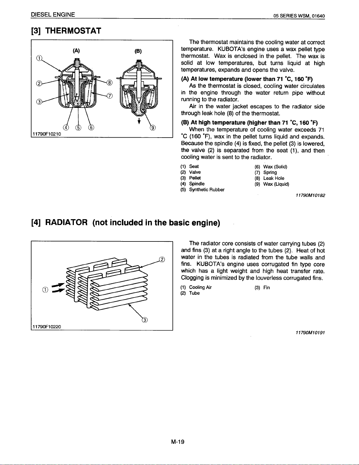
The thermostat maintains the
temperature. KUBOTA's engine uses a wax
thermostat. Wax
solid at
low
temperatures, expands
(A) At low
temperature
As the thermostat
in
the engine through the water return pipe without
running
through
(B) At high temperature (higher than
to
the radiator.
Air
in
the water jacket escapes to the radiator side
leak hole
is
enclosed
temperatures, but turns
and
(lower than
is
closed, cooling water
(8)
of the thermostat.
When the temperature of
·c
(160
·F),
wax
in
the pellet
Because the
the valve
cooling
(1)
Seat
(2)
Valve
(3)
Pellet
(4)
Spindle
(5)
Synthetic Rubber
(2)
water
spindle
is
(4)
is fixed, the pellet
is
separated from the seat
sent to the radiator.
cooling
in
the
opens the
cooling
turns liquid
(6)
Wax
(7)
(8)
(9)
(Solid)
Spring
Leak
Wax (Liquid)
water at correct
pellet
pellet.
The wax
liquid at high
valve.
71
oc,
160
circulates
71
OC,
160
water exceeds
and expands.
(3)
is
lowered,
(1
),
and
Hole
11790M10182
type
is
OF)
OF)
71
then
[4]
RADIATOR
11790F10220
(not included
in
the basic engine)
The radiator core consists of water carrying tubes
and
fins
water
in
fins. KUBOTA's engine uses corrugated fin type core
which has a
Clogging
(1)
Cooling
(2)
Tube
{3)
at a right
the tubes
is
minimized by the
Air
light
is
weight
angle
to the tubes
{2).
Heat of hot
radiated from the tube walls
and
high heat transfer rate.
louverless
(3)
Fin
corrugated fins.
11790M10191
(2)
and
M-19
Page 20
DIESEL ENGINE
[5]
RADIATOR CAP
05 SERIES
WSM,
01640
11790F1
(A)
(B)
0230
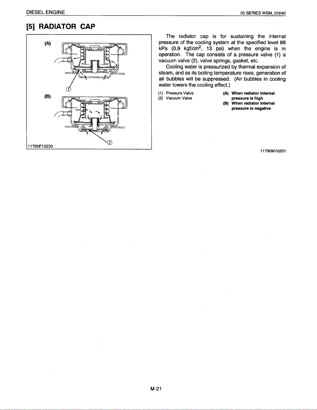
The radiator cap
pressure of the
kPa (0.9 kgf/cm
cooling system at the specified
is
for sustaining the internal
2
,
13
psi) when the engine
operation. The cap consists of a pressure
vacuum
steam,
air bubbles
water lowers the
(1)
(2)
valve
(2),
Cooling water
and
as its boiling temperature rises, generation of
will
Pressure
Vacuum
Valve
Valve
valve springs, gasket, etc.
is
pressurized by thermal expansion of
be
suppressed. (Air bubbles
cooling effect.)
(A) When radiator
pressure
(B) When radiator
pressure
is
is
level
valve
in
cooling
internal
high
internal
negative
11790M10201
is
(1)
88
in
a
M-21
Page 21
DIESEL ENGINE
II
INTAKE
[1]
AIR
CLEANER (not included
I
EXHAUST SYSTEM
in
the basic engine}
05 SERIES WSM, 01640
01640F10100
[2]
MUFFLER (not included
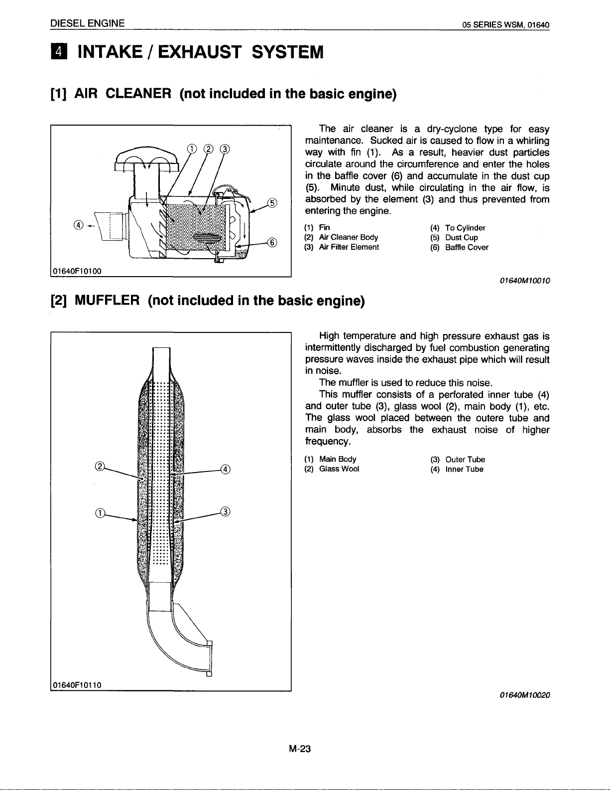
The air
maintenance. Sucked air is caused to flow
way with fin (1). As a
circulate
in
the
(5).
absorbed by the
entering the engine.
(1)
Fin
(2)
Air Cleaner
(3)
Air
in
the basic engine}
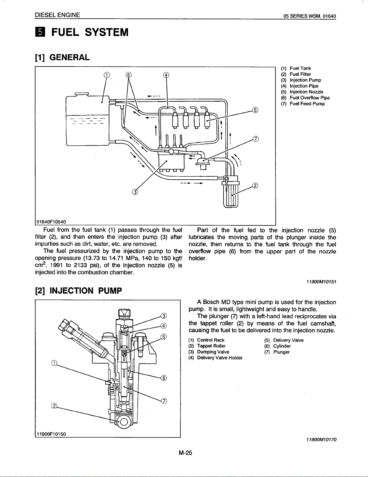
High temperature and high pressure exhaust gas is
intermittently
pressure waves inside the exhaust pipe which
in
noise.
The
This
and outer tube
The
glass wool placed
main body, absorbs the exhaust noise of higher
frequency.
cleaner
around the circumference and enter the
baffle
cover
Minute dust, while circulating
Body
Filter Element
discharged by
muffler
muffler
is
a dry-cyclone
result,
(6)
and accumulate
element
is used to reduce this noise.
consists of a perforated inner tube
(3),
glass wool
between the outere tube and
heavier dust
{3)
and thus prevented from
(4)
To
(5)
Dust Cup
(6)
Baffle Cover
fuel
combustion generating
(2), main body
type for easy
in
in
the air flow, is
Cylinder
in
a whirling
particles
holes
the dust cup
01640M10010
will result
(4)
(1),
etc.
01640F10110
(1)
Main Body
(2)
Glass Wool
(3)
(4)
Outer
Inner
Tube
Tube
01640M10020
M-23
Page 22
DIESEL ENGINE
II
FUEL SYSTEM
[1]
GENERAL
05
SERIES
(1)
Fuel
(2)
(3)
(4)
(5)
(6)
(7)
Tank
Fuel Filter
Injection
Injection
Injection Nozzle
Fuel Overflow Pipe
Fuel
Feed Pump
WSM,
Pump
Pipe
01640
01640F10540
Fuel
from the
filter
(2),
and
impurties such
The
fuel
opening pressure (13.73 to
2
cm
,
1991
fuel
tank
(1)
passes through the
then enters the injection pump
as
dirt, water,
etc.
are removed.
pressurized by the injection pump to the
14.71
MPa,
to 2133 psi), of the injection nozzle
injected into the combustion chamber.
[2]
INJECTION
PUMP
140
(3)
to
150 kgf/
fuel
after
(5)
Part
of the
lubricates
fuel fed to the injection
the moving parts of the
nozzle, then returns to the
overflow pipe
(6)
holder.
is
A Bosch
pump.
The
the tappet
causing the
(1)
Control
(2)
Tappet Roller
(3)
Dumping
(4)
Delivery Valve Holder
MD
type mini pump
It
is
small, lightweight
plunger
(7)
roller
fuel
to
Rack
Valve
plunger inside the
fuel
tank through the
from the upper part of the
11900M10151
is
used for the injection
and
with a
(2)
by
be
delivered
easy to
left-hand lead
means of the
into the injection
(5)
Delivery Valve
(6)
Cylinder
(7)
Plunger
handle.
reciprocates via
fuel
nozzle
nozzle
camshaft,
nozzle.
(5)
fuel
11900F10150
11900M10170
M-25
Page 23
DIESEL ENGINE
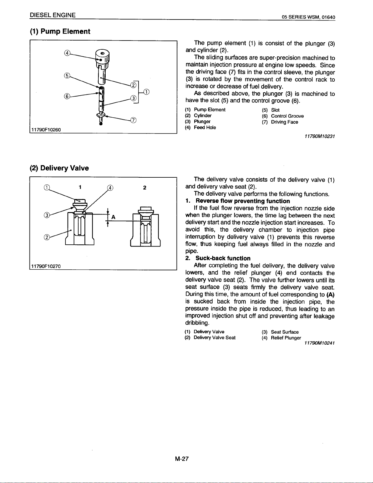
(1) Pump Element
05
SERIES WSM,
01640
11790F1 0260
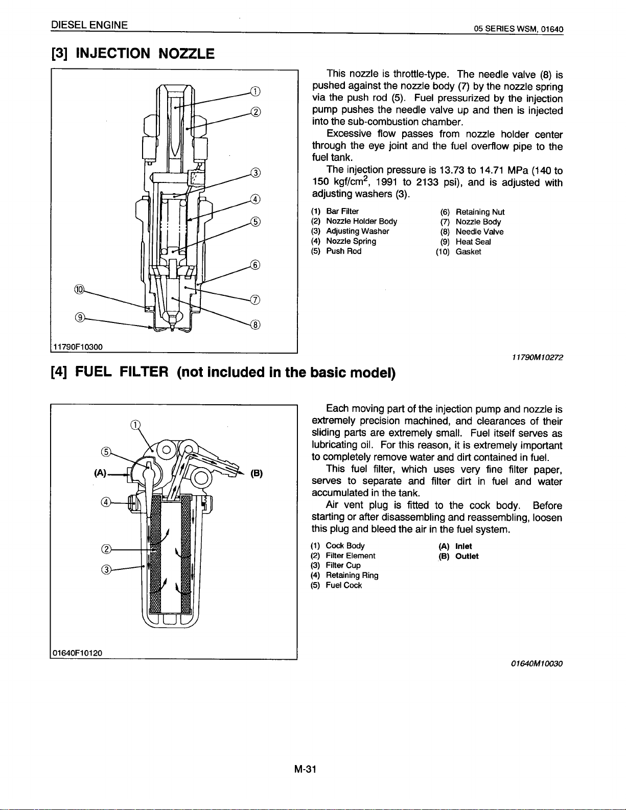
(2)
Delivery Valve
11790F10270
The pump
and cylinder
The sliding
maintain injection pressure at engine
the driving face
(3)
is rotated by the movement of the
increase or decrease of
As
described above, the plunger
have the
(1) Pump Element
(2)
Cylinder
(3)
Plunger
(4)
Feed
Hole
The
delivery valve
4
A
2
and delivery valve
The
delivery valve performs the following functions.
1.
Reverse
If
the
when the
delivery
avoid this, the
interruption by
flow, thus keeping
element
(1)
is consist of the
(2).
surfaces are super-precision machined to
low
speeds.
(7)
fits
in
the
control sleeve,
control
fuel delivery.
(3)
is machined to
slot
(5)
and the
flow
fuel flow
plunger lowers, the time
start and the
delivery
delivery valve
control
consists of the
seat
(2).
groove
(5)
Slot
(6)
Control
(7)
Driving Face
(6).
Groove
delivery valve
preventing function
reverse from the injection
lag
between the next
nozzle
injection start increases. To
chamber to injection pipe
(1)
prevents this reverse
fuel always filled
in
the
plunger
(3)
Since
the
plunger
rack to
11790M10231
(1)
nozzle
nozzle
side
and
pipe.
2.
Suck-back function
After
completing the
lowers,
delivery valve
seat surface
and the relief plunger
seat
(3)
During this time, the amount of
is
sucked back from inside the injection pipe, the
pressure inside the pipe is reduced, thus
improved injection shut off and preventing after
(2).
seats
fuel delivery,
The
valve further lowers until
firmly
the
(4)
end contacts the
the
delivery valve
delivery valve
fuel corresponding to
leading
its
seat.
(A)
to an
leakage
dribbling.
(1)
Delivery Valve
(2)
Delivery Valve Seat
(3)
Seat Surface
(4)
Relief Plunger
11790M10241
M-27
Page 24

DIESEL ENGINE
05
SERIES
WSM,
01640
(3) Dumping
11790F10280
Valve
(4) Injection Control
1.
At
fuel
injection
2
Since
spring,
as without dumping
dumping
fuel
is pressure-fed to injection
valve
is pushed up to press
valve.
nozzle
the
the same
2. At suck-back
At
suck-back
returns through dumping
injection is apt to occur
reaction
of
suck-back
As a result
perfectly
clogging, durability
1.
No
fuel delivery
At
the engine stop position
lengthwise slot (1) on the
hole
(5). And the
hole
during the entire stroke
The
pressure in the delivery
up
and no
2.
Fuel delivery
The
plunger
by
delivery valve
valve orifice.
by
after fuel
reflex
injection fuel
Generally
second
pressure due to
sudden pressure drop when changing into
by
delivery valve
of
by
dumping valve and
of
delivery
fuel
can be forced to the injection
(2) is rotated (see figure)
from high injection pressure.
preventing this second injection
dissolving nozzle
injection
nozzle
of
the
control
plunger
(2)
aligns
chamber (4) is
of
the
plunger.
chamber does not
is improved.
11790M10251
rack (3), the
with the feed
led
to the feed
build
nozzle.
by
the
control
rack (3).
When the
closed.
up and forcefeeds the
the
control
The
plunger
The pressure
groove
amount
of
(6)
the
is pushed up, the feed hole
in
the delivery
fuel
to
meets the feed
fuel
corresponds to
the
injection
chamber (4)
nozzle until
hole
(5).
the
distance
(5) is
builds
"A".
(1)
(2)
(3)
Slot
Plunger
Control
Rack
(4)
Delivery
(5)
Feed
(6)
Control Groove
Chamber
Hole
11900F10160
11900M10181
M-29
Page 25
DIESEL ENGINE
(3]
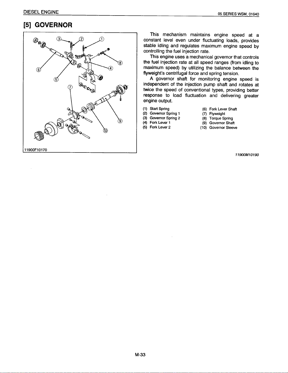
INJECTION NOZZLE
05 SERIES WSM, 01640
11790F1
(4]
0300
FUEL
FILTER (not included
in
the basic
This nozzle
is
throttle-type. The needle valve
pushed against the nozzle body
via the
push
rod
(5).
Fuel
pressurized by the injection
pump pushes the needle valve
into the sub-combustion chamber.
Excessive flow
through the eye joint
passes from nozzle holder center
and
the fuel
fuel tank.
The injection pressure is 13.73 to
kgf/cm
Filter
Rod
2
,
1991
to 2133 psi),
(3).
Body
(6)
(7)
(8)
(9)
(10)
150
adjusting washers
( 1 )
Bar
(2)
Nozzle Holder
(3)
Adjusting Washer
(4)
Nozzle Spring
(5)
Push
model)
(7)
by
the nozzle spring
up
and then
is
overflow pipe to the
14.71
MPa
and
is
adjusted with
Retaining Nut
Nozzle
Body
Needle
Valve
Heat Seal
Gasket
11790M1
(8)
is
injected
(140
to
0272
01640F10120
(B)
Each
moving part of the injection pump and nozzle
extremely precision machined, and clearances of their
sliding parts are extremely small. Fuel itself serves
lubricating
to completely remove water
This fuel
serves
accumulated
Air vent
oil.
For this reason, it
is
and
dirt contained
extremely important
filter, which uses very fine filter paper,
to
separate
in
plug
and
filter dirt
in
fuel
the tank.
is
fitted to the cock body. Before
in
and
as
fuel.
water
starting or after disassembling and reassembling, loosen
this plug
(1)
(2)
(3)
(4)
(5)
and
bleed the air
Cock Body (A) Inlet
Filter Element
Filter
Cup
Retaining Ring
Fuel
Cock
in
the fuel
(B)
Outlet
system.
01640M10030
is
M-31
Page 26
DIESEL ENGINE
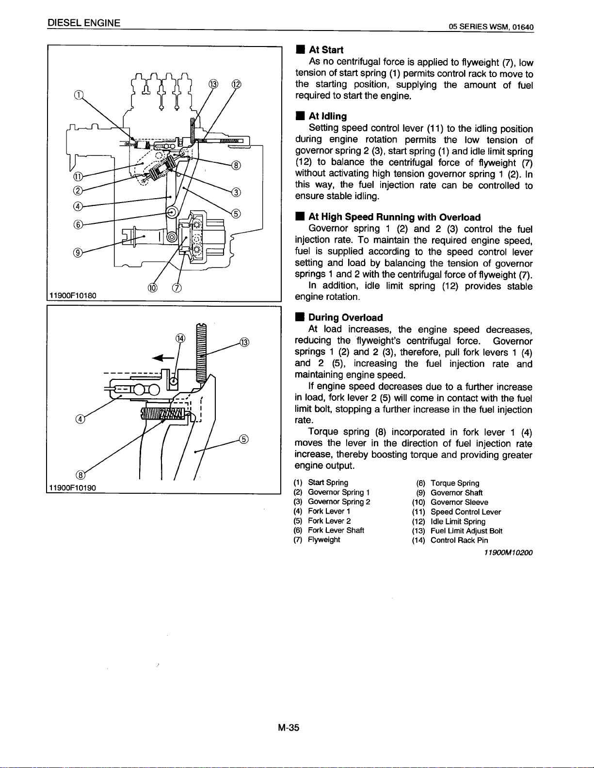
[5]
GOVERNOR
05 SERIES WSM, 01640
This mechanism maintains engine speed at a
constant
stable idling and regulates
controlling
the fuel
maximum speed)
flyweight's
level
even under fluctuating
the
fuel
injection
This engine uses a
injection rate at
by
centrifugal
loads,
maximum engine speed by
rate.
mechanical
all
speed ranges (from
utilizing
force
and
governor that
the
balance
spring tension.
provides
between the
A governor shaft for monitoring engine speed
independent of the injection pump shaft
twice the speed of
response to load fluctuation
conventional
types, providing better
and
and
delivering
rotates at
engine output.
(1)
Start
(2)
(3)
(4)
(5)
Spring
Governor Spring 1
Governor Spring 2
Fork Lever 1
Fork Lever 2
Fork Lever
(6)
Flyweight
(7)
Torque Spring
(8)
Governor
(9)
(10) Governor
Shaft
Shaft
Sleeve
controls
idling
to
is
greater
11900F1 0170
11900M10190
M-33
Page 27
DIESEL ENGINE
11900F10180
05 SERIES WSM, 01640
•
At
Start
As
no
centrifugal
tension of start spring
the starting position,
force
is
applied to flyweight
(1)
permits control
supplying
rack to move to
the amount of
required to start the engine .
•
At
Idling
Setting
during engine rotation permits the
governor spring 2
(12)
speed control lever
(3),
start spring
(11)
to the
(1)
and
idling
low
tension of
idle limit
to balance the centrifugal force of flyweight
without activating high tension governor spring 1
this
way,
the
fuel
injection rate
ensure
•
injection
fuel
setting
stable
idling.
At High
Speed Running with Overload
Governor spring 1
rate.
To maintain the required engine speed,
is
supplied
and
load
according
by
balancing
(2)
springs 1 and 2 with the centrifugal
In
addition,
idle limit spring
can
be
controlled
and
2
(3)
control the
to
the speed control
the tension of governor
force of flyweight
(12)
provides
engine rotation.
(7),
low
fuel
position
spring
(7)
(2).
In
to
fuel
lever
(7).
stable
11900F10190
•
During
At
Overload
load increases, the engine speed decreases,
reducing the flyweight's centrifugal force. Governor
springs 1
and
2
(2)
and
(5),
increasing the
2
(3},
therefore,
fuel
pull
fork
levers
1
injection rate and
(4)
maintaining engine speed.
If
engine speed decreases due to a further increase
in
load, fork
limit bolt,
lever
2
(5)
will
come
in
stopping a further increase
contact with the
in
the
fuel
injection
fuel
rate.
Torque spring
moves the
lever
increase, thereby boosting torque
(8)
incorporated
in
the direction of
in
fork
lever 1
fuel
injection rate
and
providing greater
(4)
engine output.
(1)
Start
(2)
(3)
(4)
(5)
(6)
(7)
Spring
Governor Spring
Governor Spring
Fork Lever 1
Fork Lever 2 (12)
Fork Lever
Ayweight
1
2
Shaft
Torque
(8)
Governor
(9)
Governor
(10)
Speed Control Lever
(11)
Idle
Limit
Fuel
(13)
(14)
Limit Adjust
Control Rack Pin
Spring
Shaft
Sleeve
Spring
Bolt
11900M1
0200
M-35
Page 28
DIESEL ENGINE
[6]
AUTOMATIC
01640F10090
01640F10130
ADVANCE
TIMER
05
SERIES WSM,
(not included
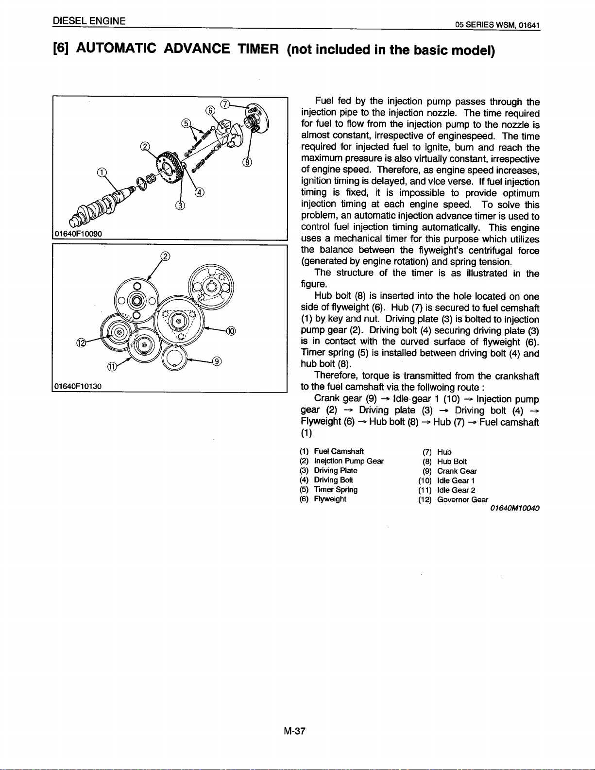
Fuel
fed by the injection pump passes through the
injection pipe to the injection nozzle.
for
fuel
to flow from the injection pump to the
almost
required for injected
maximum pressure is
of
ignition timing is delayed, and vice verse.
constant, irrespective
engine speed. Therefore, as engine speed increases,
in
the basic
model)
The time required
of
enginespeed. The time
fuel
to ignite, burn and reach the
also virtually constant, irrespective
If
fuel
nozzle
injection
timing is fixed, it is impossible to provide optimum
injection timing
at
each engine speed.
To
solve
problem, an automatic injection advance timer is used to
control fuel
injection timing automatically. This engine
uses a mechanical timer for this purpose which utilizes
the
balance
(generated by engine rotation) and
The structure
between the flyweight's centrifugal force
spring tension.
of
the timer is
as
illustrated
figure.
Hub bolt
side
of
(1)
by key and nut. Driving
pump gear (2). Driving
is in contact with the curved surface
Timer
hub
bolt
(8)
is inserted into the hole located
flyweight (6). Hub
spring
(5)
is installed
(8).
(7)
is secured to
plate
(3)
bolt
(4)
securing driving plate
between driving
is
bolted
of
fuel cemshaft
to injection
flyweight (6).
bolt
Therefore, torque is transmitted from the crankshaft
to the
fuel
Crank gear
gear (2) Flyweight
camshaft via the
(9)
- Idle gear 1
Driving plate
(6)
-
Hub
follwoing route :
(3)
bolt
(8)
-
(1
0) -
- Driving
Hub
(7)
Injection pump
bolt
- Fuel
camshaft
(1)
01641
is
this
in the
on one
(3)
(4) and
(4)
-
(1)
(2)
(3)
(4)
(5)
(6)
M-37
Fuel
Camshaft
lnejction Pump Gear
Driving
Plate
Driving
Bolt
Timer Spring
Flyweight
(7)
Hub
(8)
Hub
(9)
Crank Gear
(1
0}
Idle
(11}
Idle
(12}
Governor Gear
Bolt
Gear 1
Gear 2
01640M10040
Page 29
DIESEL ENGINE
01640F10140
-
-
05
SERIES
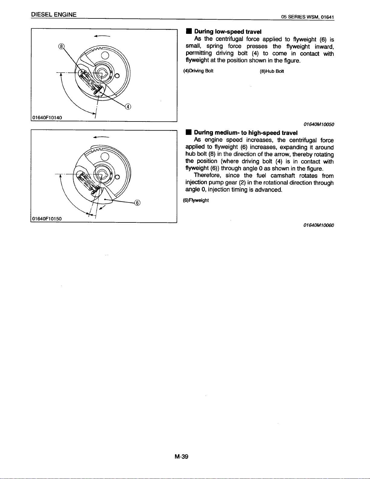
•
During
As
small, spring force presses the flyweight inward,
permitting driving
flyweight at the position shown
(4)Driving
•
During medium- to high-speed travel
As
applied to
hub
the position (where driving bolt
flyweight
Therefore, since the
injection pump gear
angle
(6)Fiyweight
low-speed travel
the
centrifugal
Bolt
engine speed increases, the
flyweight
bolt
(8)
in
the direction of the arrow, thereby rotating
(6))
through
0,
injection timing
force
applied
bolt
(4)
to come
(8)Hub
(6)
increases, expanding it around
angle 0 as shown
fuel
(2)
in the rotational direction through
is
advanced.
to flyweight
in
the figure.
Bolt
(4)
is in contact with
camshaft rotates from
WSM,
in
contact with
01640M10050
centrifugal
in
the figure.
01641
(6)
force
is
01640F10150
01640M10060
M-39
Page 30
DIESEL ENGINE
II
ELECTRICAL SYSTEM
[1]
CHARGING SYSTEM
(1) Alternator
05
SERIES
WSM,
01640
01640F10160
(2)
IC
Regulator
01640F10170
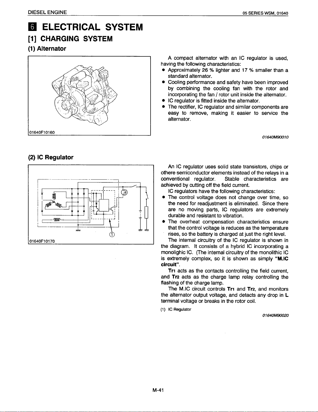
A compact alternator with an IC
having the
•
Approximately 26 % lighter and
standard alternator.
•
Cooling performance and safety have been improved
by
incorporating the fan
• IC
•
The rectifier,
easy
alternator.
An
othere semiconductor elements instead of the relays in a
conventional regulator. Stable
achieved by cutting off the field current.
IC
•
The control voltage does not change over time, so
the need for readjustment is eliminated. Since
are no moving parts,
durable and resistant
•
The overheat compensation characteristics ensure
that the control voltage is reduces as the temperature
rises, so the battery is charged at just the right level.
The internal circuitry of the
the diagram.
monolighic
is extremely complex, so it is shown as simply
circuit".
Tn
and
flashing
The
the alternator output voltage, and detacts any drop in
terminal voltage or breaks in the rotor coil.
(1)
IC
following
combining the cooling fan with the rotor and
regulator is fitted inside the alternator.
to
remove, making it easier to service the
IC
regulator uses solid state transistors, chips or
regulators have the
I
C.
acts as the contacts
Tr2
acts as the charge lamp relay controlling
of
the charge lamp.
M.IC
Regulator
characteristics:
I
rotor unit inside the alternator.
IC
regulator and similar components are
following
IC
regulators are extremely
to
vibration.
It
consists
(The internal circuitry of the monolithic
circuit controls
of
a hybrid
controlling
Tr1
regulator is used,
17
%
smaller than a
01640M90010
characteristics are
characteristics:
IC
regulator is shown in
IC incorporating a
the field current,
and
Tr2,
and monitors
01640M90020
there
IC
"M.IC
the
L
M-41
Page 31

DIESEL ENGINE
6
TURBO
CHARGER
SYSTEM
05
SERIES WSM,
01640
01640F10180
(1)
Actuator
(2)
Turbine Housing
(3)
Snap
(4)
Ring
Lock Nut
This turbo charger consists
compressor mounted on a
flow turbine driven by exhaust
The turbo charger is
to
the engine than for a non-supercharged engine, which
(5)
(6)
(7)
(8)
common
gas
capable
Compressor
Turbine Wheel
Piston Ring
Bearing
basically
of
Wheel
a
shaft with a
from the engine.
of
supplying
centrifugal
double
far
more air
is without such a charger.
In applications
low, the turbo charger is
where the
capable
boost
of
pressure is
relatively
reducing the smoke
(9)
Snap
(10)
(11)
(12)
Ring
Snap
Ring
Piston Ring
Oil
Deflector
(TD025) (14)
concentration, the concentration
(13)
Thrust
0-ring
(15)
Thrust Bearing
(16)
Thrust Ring
in
Sleeve
the
cylinder, fuel
consumption, and deterioration in performance
elevated
terrain
by
increasing the
amount
of
air
engine.
In applications
charger is
engine output by increasing the
engine, in addition
where the
capable
to
boost
pressure is high, the
of
providing a
large
amount
increase in
of
air into the
the above mentioned advantages.
01640M10070
to
at
the
M-43
Page 32

DIESEL ENGINE
(1) Mechanism
(r
01640F10190
c
___
I
I
I
_l
__
_
05 SERIES WSM, 01640
•
Turbocharger Works
While the engine is running, exhaust gas passes
through the exhaust manifold to rotate the turbine wheel
(3)
of
the turbocharger
Rotation
wheel
on the same shaft. As the compressor wheel rotates, air
is sucked in, compressed, and sent into the cylinder.
The higher density of the compressed air per cylinder
volume results in increased output compared with nonturbocharged engines of the same displacement.
•
Advantages
Turbocharged engine have the following advantages:
1.
Despite the increase in output, there is little increase
in friction loss. Therefore, good mechanical
efficiency is insured.
2.
During overlap (when both the suction and exhaust
valves are open), compresed air forces out exhaust
gas and fills the cylinder with fresh air. This
increases combustion efficiency.
3.
Improvements in mechanical and combustion
efficiency lead to a lower fuel consumption.
(1)
Air
(2)
Turbocharger
(3)
Turbine
(4)
Waste Gate
(5)
Exhaust
of
the turbine wheel rotates the compressor
(7)
at the same speed because both wheels are
Cleaner
Wheel
Valve
Valve
(2)
at high speed.
(6)
Intake Valve
(7)
Compressor
(a)
Air
(b) Exhaust Gas
Wheel
01640M10080
M-45
Page 33

DIESEL ENGINE
(2)
Turbine
05 SERIES
WSM,
01641
01640F10200
(b)
This is a radial flow
The turbine
wheel
and shaft is designed to
turbine.
wheel assembly
(3) uniting the turbine
balance
even at high
speeds.
The turbine housing
As
the passage becomes
gas flow rate increases so that the turbine
(2)
has a vortex gas passage.
smaller (from
"A"
to
"B"},
is
rotated at
the
high speeds.
The turbine back
housing and bearing (floating metal)
plate
(1)
prevents the bearing
inside from being
directly exposed to the heat of the exhaust gas on the
turbine
(1) Turbine Back
(2)
(3) Turbine
wheel
side.
Turbine Housing
Plate
Wheel Assembly
(a)
From Cylinder
(b)
To
Exhaust
Muffler
01640F10210
(3)
Compressor
01640F10220
01640M1
A
radial flow
compressor is used.
The compressor consists of a cast compressor
0090
wheel
(1}, bearing housing (3}, insert (2), compressor cover (4).
Air is sucked at high speed by the compressor
As
it passes through the spiral
its speed is reduced to the proper
the
cylinder.
The compressor
wheel is a precision-cast
component, which maintains the proper
high speeds.
Its blades
are curved backward to ensure
passage in the housing,
level
and forced into
balance even at
wheel.
the highest performance.
The compressor housing is designed to
air flow drawn by the
(1) Compressor
(2)
Insert
(3)
Bearing Housing
(4) Compressor Cover
Wheel
wheel
and increase its pressure.
(a)
To
Cylinder
(b) From
the
Air
regulate the
Cleaner
01640M10100
M-47
Page 34

DIESEL ENGINE
(4) Bearing
01640F10230
05 SERIES WSM, 01640
The shaft rotates at a very high speed-tens of
thousands of revolutions per minute. To withstand high
(5)
speeds, the bearings
on
bearings float
housing
(4)
a film
and
rotate to reduce the sliding friction.
The shaft also receives thrust force
on
direction)
the compressor side from both the turbine
and compressor wheels. This load
(3)
bearing
ring
fitted between the thrust sleeve
(2)
which
is
secured to the shaft
use floating metals. These
oil
between the shaft
is
borne by the thrust
and
(in
(1)
and
turns together
the axial
and
bearing
thrust
with the shaft. ·
Lubricating
fed from the engine's
oil
pump enters
oil
the bearing section through the top of the bearing
and
housing
passes through the internal passages,
lubricating the bearings. After that, it returns to the
engine from the bottom of the bearing housing.
(1)
Thrust Sleeve
(2)
Thrust Ring
(3)
Thrust Bearing
{4) Bearing Housing
(5)
Bearing
(a)
(b)
From
To
the
Engine
Engine
Oil
Pump
01640M10110
M-49
Page 35

DIESEL ENGINE
(5) Seals (Piston Rings)
05 SERIES WSM, 01640
01640F10240
\
@
When lubricating oil leaks on the turbine
compressor wheel side, it will adhere
housing. the oil
carbon. Such contamination will destroy the balance
the rotating shaft and prevent normal operation.
To
prevent this problem, lubricating oil is sealed
the follwoing parts:
the
On
* A piston ring (1} is placed
*
The
shaft itself has an oil fling portion (2}.
On the compressor wheel side
* A piston ring (3} is placed
may
then be contaminated with dust
turbine wheel side
over
over
to
the wheel
the shaft.
the thrust sleever (5}.
or
or
or
of
by
* The oil deflector (4}, which is placed on the thrust
sleeve (5}, prevents oil from leaking to the piston
ring side.
In addition, oil is prevented from leaking to the
outside by a seal ring (square rubber ring} placed
between the center housing and the back plate.
(1)
Piston Ring
(on
the Turbine Side)
(2)
Oil Fling Portion
(3)
Piston Ring
(Compressor Side)
Oil Deflector
(4)
Thrust Sleeve
(5)
(6)
Thrust Ring
01640F10250
01640M10120
M-51
Page 36

SERVICING
CONTENTS
• GENERAL .........................................................................................................
[1]
ENGINE IDENTIFICATION ........................................................................
(1)
Model Name and Engine Serial Number ...............................................
(2)
Cylinder Number ...................................................................................
[2]
GENERAL PRECAUTION ......................................................................... S-3
[3]
TIGHTENING TORQUES .......................................................................... S-5
(1)
Tightening torques for special use screws, bolts and nuts .................... S-5
(2)
Tightening torques for general use screws, bolts and nuts ................... S-5
[4]
TROUBLESHOOTING ................................................................................ S-8
[5]
SERVICING SPECIFICATIONS .............................................................. S-19
(1)
Engine Body ........................................................................................ S-19
(2)
Lubricating System .............................................................................. S-25
(3)
Cooling System ................................................................................... S-25
(4)
Fuel System ........................................................................................ S-26
(5)
Electrical System ................................................................................. S-27
[6]
MAINTENANCE CHECK LIST.. .............................................................. S-44
[7]
CHECK AND MAINTENANCE ................................................................ S-47
(1)
Daily Check Points .............................................................................. S-47
(2)
Check Point of Every 50 hours ............................................................ S-49
(3)
Check Point of Every 100 hours ..........................................................
(4)
Check Point of Every 800 hours .......................................................... S-57
(5)
Check Point of 1500 hours (Serial
[8]
SPECIAL TOOLS ..................................................................................... S-59
• ENGINE BODY .............................................................................................. S-73
CHECKING AND ADJUSTING ..................................................................... S-73
DISASSEMBLING AND ASSEMBLING ........................................................ S-75
[1]
DRAINING WATER AND OIL.. .............................................................. S-77
[2]
EXTERNAL COMPONENTS ................................................................... S-77
[3]
CYLINDER HEAD AND VALVES .......................................................... S-79
[4]
GEAR CASE ............................................................................................ S-83
[5]
PISTON AND CONNECTING ROD ....................................................... S-95
[6]
LYWHEEL AND CRANKSHAFT ...........................................................
SERVICING .................................................................................................. S-105
[1]
CYLINDER HEAD .................................................................................. S-105
[2]
TIMING GEAR AND CAMSHAFT ........................................................ S-115
[3]
PISTON AND CONNECTING ROD ..................................................... S-119
[4]
CRANKSHAFT ........................................................................................ S-125
[5]
CYLINDER .............................................................................................. S-137
• LUBRICATING SYSTEM .............................................................................
CHECKING ...................................................................................................
SERVICING ..................................................................................................
[1]
OIL PUMP ..............................................................................................
• COOLING SYSTEM ..................................................................................... S-145
CHECKING ................................................................................................... S-145
(1]
FAN
BELT .............................................................................................. S-145
[2]
RADIATOR ............................................................................................. S-145
DISASSEMBLING AND ASSEMBLING ...................................................... S-147
No:-
489290) .............................. S-59
S-1
S-1
S-1
S-1
S-51
S-101
S-141
S-141
S-141
S-141
Page 37

D FUEL SYSTEM .............................................................................................
CHECKING AND ADJUSTING ....................................................................
[1]
INJECTION PUMP .................................................................................
[2]
INJECTION NOZZLE. ............................................................................. S-155
DISASSEMBLING AND ASSEMBLING ...................................................... S-157
[1]
INJECTION PUMP ................................................................................. S-157
[2]
INJECTION NOZZLE .............................................................................. S-159
B ELECTRICAL SYSTEM ................................................................................
CHECKING ....................................................................................................
[1]
STARTER ................................................................................................
[2]
GLOW PLUG .......................................................................................... S-163
DISASSEMBLING AND ASSEMBLING ...................................................... S-163
[1]
STARTER ................................................................................................ S-163
[2]
ALTERNATOR. ........................................................................................ S-165
SERVICING ...................................................................................................
[1]
STARTER ................................................................................................
[2]
ALTERNATOR ......................................................................................... S-175
• TURBO CHARGER SYSTEM .....................................................................
CHECKING ....................................................................................................
DISASSEMBLING AND ASSEMBLING ...................................................... S-185
S-151
S-151
S-151
S-161
S-161
S-161
S-171
S-171
S-181
S-181
Page 38

DIESEL ENGINE
BJ
GENERAL
[1]
ENGINE IDENTIFICATION
05 SERIES WSM, 01640
(1) Model
(2)
Cylinder
Name and Engine Serial
Number
8888
Number
When contacting the manufacturer,
model name and
The
cylinder
designated as shown
The sequence of cylinder
3
and
No.
4 starting from the gear case side.
serial
number.
numbers of
in
05
SERIES diesel engine are
the figure.
numbers is given as
always
specify
No.
~rour
engine
01640510010
1,
No.
2,
No.
01640F10260
01640510020
S-1
Page 39

DIESEL ENGINE
[2]
GENERAL
(A)
11790F00051
PRECAUTION
(B)
•
During
disassembly, carefully
area to prevent confusion
be
replaced
in
their
05 SERIES
arrange removed parts
later.
Screws,
bolts
original position to prevent reassembly
WSM,
in
and nuts
errors.
•
When
special tools
tools. Special tools
make according
•
Before
always
• Remove
•
Use
disassembling
disconnect the grounding cable
oil
and
only KUBOTA genuine parts for parts
maintain engine performance
•
Gaskets and
Apply
grease
•
When reassembling external
them
so
that the sharp edge faces against the direction from
which force
•
Be
sure to perform run-in the serviced
Do
not attempt to give heavy load
may
A
CAUTION
•
Certain components used
gasket, exhaust gasket, etc.) contain asbestos. Handle with
care according to safety regulation.
(1)
Grease (A)
(2)
Force
(3)
Place
Direction of Force
result
the
Sharp
is
to the engine.
are required, use
which are not
to
the drawings provided.
or servicing
KUBOTA
frequently used
live
from the battery first.
dirt from parts before measuring.
and
to ensure safety.
0-rings
to new
must
0-rings
be
or
replaced
oil
seals
or
internal
before
applied.
or
at once, or serious damage
in
this engine
External Snap Ring
(B)
Edge against the
Internal Snap
genuine
should
wires, make sure to
replacement
during
reassembly.
assembling.
snap rings, position
reassembled
{cylinder
Ring
engine.
01640510030
01640
a clean
should
special
be
to
head-
S-3
Page 40

DIESEL ENGINE
TIGHTENING TORQUES
[3]
Screws, bolts and nuts must be tightened to the specified torque using a torque wrench, several screws, bolts
proper sequence and at the proper torque.
tightened
and nuts such as those used on the cylinder head must
(1) Tightening torques for
NOTE
•
removing and
• In
employed,
if
tool,
marked screws,
"*"
• For
tightening.
letter "M"
The
•
nominal
the
threads.
Cylinder head cover cap nuts
*
Cylinder head screws
*
Main bearing case screws 1
*
Main bearing case screws 2
*
Flywheel screws
*
Connecting rod screws
*
Rocker arm bracket nuts
*
gear shaft screws
Idle
*
Crankshaft (Serial
*
end bolt
Bearing case cover screws
*
Glow plugs
Nozzle holder assembly
Oil switch taper screw
Injection
Overflow pipe assembly retaining nuts
Starter's terminal
pipe retaining nuts
applying
must be used with enough care not to get them seized.
Size
in
outside diameter in mm
Item
(Serial
(Serial
(Serial
mounting nut
B
(2) Tightening torques for
When the tightening torques are not specified, tighten the screws, bolts and nuts according to the table below.
special
bolts
the
and nuts on the table, apply
bolts
Pitch means that the screw,
x
- 604086)
No:
604087
No:
No: - 489290)
No: 489291
general
use screws,
and nuts marked with
the threads. The pitch is the
of
Size
M7
M10
M8
M9
M10
M8
M7
M6
M14x1.5
M14
-)
M6
M10x1.25
-)
M8
M20
PT 1/8
M12
M12
use screws,
Standard Screw and
be
bolts
bolt
Pitch
x
1.0
X
1.25 63.7to.68.6 6.5 to
X
1.25 29.4 to 34.3
X
1.25
X
1.25
X
1.0
X
1.0
X
1.0
X
1.5 235.4 to 245.2
X
1.0
X
1.0
X
1.5
X
1.5 24.5 to 34.3
X
1.5 19.6 to 24.5
X
M8
bolts
Bolt
in
and nuts
a pneumatic wrench or
"*",
engine
nut dimension stands for metric. The size is
or
6.9 to 8.8
49.0
53.9 to 58.8
41.2 to
21.6 to 26.5
9.8 to 11.3
142.2 to
9.8 to 11.3
19.6 to 24.5
7.8 to 14.7
49.0
14.7 to 19.6 1.5 to
8.8 to11.8
oil to their threads and seats before
nominal
N·m
to 53.9
46.1
152.0
to 68.6
distance
kgf·m
0.7 to 0.9
3.0 to 3.5 21.7 to 25.3
5.0 to 5.5 36.2 to 39.8
5.5 to 6.0
4.2 to 4.7
2.2 to 2.7
1.00to
14.5 to 15.5
24.0 to
1.00
2.0
0.8
5.0
2.5 to 3.5
2.0 to 2.5 14.5 to
0.9
and nuts
Special
@
05 SERIES WSM, 01640
01640810760
similar
in
7.0 47.0
1.15
25.0 173.6 to
to 1.15 7.2 to 8.3
to 2.5
to 1.5
7.0
to
2.0
to 1.2
Screw
pneumatic
mm between two
ft-lbs
to 6.5
5.1
to
39.8 to 43.4
to
30.4
15.9 to 19.5
7.2 to 8.3
104.9to
14.5 to
5.8 to
36.2 to 50.6
10.8to14.5
18.1
6.5 to 8.7
11790810643
Bolt
and.·
(j)
50.6
34.0
112.1
180.8
18.1
10.8
to 25.3
18.1
~
M6
M8
M10
M12
Screw
tightening, be sure to check out the numbers as shown below.
Punched number
and bolt material grades are shown by numbers punched
None or 4 Standard screw and bolt
7 Special
N·m kgf·m
to 0.95
45.1
0.80
1.8 to
to 4.6
4.0
SS41
S43C, S48C
7.9 to 9.3
17.7to20.6
39.2 to
62.8 to 72.6 6.4 to 7.4
and bolt material grade
Screw
screw and bolt
2.1
S20C
,
(Refined)
S-5
ft-lbs
5.8 to 6.9 9.8 to 11.3
to 15.2
13.0
28.9 to 33.3
46.3 to 53.5 77.5 to
N·m
23.5 to 27.5
to 55.9 4.9 to 5.7 35.4 to 41.2
48.1
the screw and bolt heads. Prior to
on
90.2
kgf·m
to 1.15
1.00
2.4 to 2.8
7.9 to 9.2
ft-lbs
7.23 to 8.32
20.3
17.4 to
to 66.5
57.1
01640810040
Page 41

SERIES WSM, 01640
05
TROUBLESHOOTING
[4]
DIESEL ENGINE
Symptom
Engine Does Not
Start
Cause Solution
Replenish
Vent air S-49
Change fuel and
fuel
No
•
Air in the
•
Water
•
Probable
fuel system
the fuel system
in
repair
system
clogged Clean
• Fuel
• Fuel filter clogged
•
pipe
fuel or engine
Excessively high viscosity
temperature
low
at
with low cetane number Use specified
• Fuel
• Fuel
leak due to
loose
of
injection pipe retaining
oil
Clean or change
Use specified
engine
Tighten retaining nut
nut
• Incorrect injection timing Adjust
• Fuel
camshaft worn
• Injection nozzle clogged
• Injection
• Seizure
cylinder
Compression
•
pump malfunctioning Repair or replace
crankshaft, camshaft, piston,
of
or bearing
from
leak
cylinder
Replace
Clean S-155,
Repair or replace
Replace head
gasket, tighten
cylinder
glow
holder
• Improper
valve timing
Correct
timing gear
Piston ring and
•
Excessive
•
cylinder
clearance Adjust
valve
worn Replace
fuel
replace
or
oil
head screw,
plug and
replace
or
fuel
fuel or
fuel
nozzle
Reference
Page
-
-
-
S-53
S-51
-
-
S-151,
S-89
S-87, 153,
S-155
S-73,
S-81
153
157
-
79,
S-95
S-121, 123 ,
S-137
S-57
(Starter
Does Not
Run)
Engine Revolution
Not Smooth
Either White or Blue
Exhaust Gas
Is
Observed
Battery discharged
•
• Starter
Key switch malfunctioning Repair or replace
•
malfunctioning
• Wiring disconnected
Is
Fuel filter clogged or dirty
•
Air cleaner
•
• Fuel leak
nut
• Injection
• Incorrect
• Injection
Governor
•
Excessive engine oil Reduce
•
Piston ring
•
• Incorrect
Deficient compression
•
Charge
Repair or
replace
Connect
change
or
Clean
change
or
clogged
due to loose
injection pipe retaining Tighten retaining nut
pump malfunctioning Repair or
Clean
replace
nozzle opening pressure Adjust
nozzle stuck or clogged Repair or replace
malfunctioning
Repair
specified
to
level
liner worn or stuck Repair or replace
and
injection timing
Adjust
Adjust top clearance S-73
-
-
-
-
S-53
S-55
-
S-87, 153,
S-155
91
151
11
90
7
157
157
51
, 153
51055
S-155,
S-155,
S-
S-47,
S-121, 123,
S-137
S-
S-8
Page 42

DIESEL ENGINE
05 SERIES WSM, 01640
Symptom Probable
Overload
or Dark
Black
Either
Gray Exhaust Gas
Observed
Deficient Output
Excessive Lubricant
Consumption
Oil
•
Low grade fuel used Use specified fuel
•
Is
Fuel filter clogged Clean or change
•
Air cleaner clogged Clean or change
•
Deficient nozzle injection Repair or replace
•
• Incorrect
Engine's moving parts seem to be seizing Repair or replace
•
Uneven fuel injection Repair or replace
•
Deficient nozzle injection Repair or replace
•
Compression leak Replace head
•
• Piston ring's gap facing the same direction
ring worn or stuck
• Oil
• Piston
• Valve
ring groove worn
stem and valve guide worn
• Carnkshaft bearing, and crank pin bearing
worn
leaking due to defective seals or packing
• Oil
Mixed into
Fuel
Lubricant
Oil
• Injection pump's plunger worn
Deficient nozzle injection Repair or replace
•
• Injection pump broken
Head gasket defective
Water Mixed Into
Lubricant Oil •
Pressure
Oil
Low
Pressure
Oil
High
•
Cylinder block or cylinder head flawed
Engine oil insufficient Replenish
•
strainer clogged Clean
• Oil
Relief valve stuck with dirt Clean
•
Relief valve spring weaken or broken
•
Excessive oil clearance of crankshaft bearing Replace
•
Excessive oil clearance of crankpin bearing Replace
•
Excessive oil clearance of rocker arm bearing Replace
•
passage clogged Clean
• Oil
Different type of oil
•
pump defective Repair or replace
• Oil
Different type of oil Use specified type of
•
Relief valve defective
•
Cause
Lessen load
nozzle
injection timing Adjust
injection pump
nozzle
gasket, tighten
cylinder head screw,
glow plug and nozzle
holder
Shift
direction
Replace
Replace piston
Replace
Replace
Replace
Replace
element or injection
pump
nozzle
Replace
Replace
Replace
Replace
Use specified type
oil
oil
·Replace
Solution
ring gap
pump
Reference
Page
S-53
S-55
S-155,
S-151,
S-87,
S-153
S-155,
S-73, 79,
S-81
S-97
S-99,
S-123
S-99,
S-107, 109
S-133,
S-87,
S-155
S-79,
S-87
S-81
S-107
S-47,
S-95
S-129,
S-133
S-127
S-113
of
S-141,
-
-
157
153
-
151,
157
121,
123
135
-
153,
159
51
-
-
-
-
-
-
11790S
131,
143
10562
•
S-9
Page 43

05 SERIES WSM, 01640
DIESEL ENGINE
Symptom
Engine Overheated
Battery Quickly
Discharge
Probable Cause
Engine oil insufficient
•
Fan belt broken or elongated
•
Cooling water insufficient
•
Radiator net and radiator
•
fin clogged with dust
• Inside of radiator corroded
Cooling water flow route corroded
•
• Radiator cap defective
Overload running
•
Head gasket defective
•
• Incorrect injection timing
• Unsuitable fuel used
Battery electrolyte insufficient
•
Fan belt slips
•
Wiring disconnected
•
• Rectifier defective
Alternator defective
•
Battery
•
defective
Solution
Replenish
Replace or adjust
Replenish
Clean
Clean or replace
Clean or replace
Replace
Loosen load
Replace
Adjust
Use specified fuel
Replenish
distilled
water and charge
Adjust belt tension or
change
Correct
Replace
Replace
Change
Reference
Page
51
S-47,
S-53
-
-
-
-
S-147
-
S-81
S-151, 153
-
-
S-53
-
S-179
S-175, 177,
S-179
-
11790510571
S-10
Page 44

DIESEL ENGINE
[5]
SERVICING SPECIFICATIONS
(1) Engine Body
05 SERIES WSM,
01642
Cylinder
Cylinder
Top
Compression Pressure
Variance Among
Head
Head
Clearance
Surface Flatness
Cylinders
Valves
Valve Clearance (Cold)
Valve Seal Width
Valve
Seat Angle IN.
Item
IN.
EX.
Factory Specification
-
0.55
to
0.75 mm
0.0217
29.0
0.145
0.0057
to
0.0295
2.84 to 3.23 MPa
to
33.0
412 to
4S9 psi
-
to
0.185
to
0.0072
2.12 mm
0.0835 in
2.12 mm
0.0835
1.047
in.
kgf/cm
mm
in.
in.
rad.
2
so·
Allowable
0.05
mm
0.0019
-
2.25 MPa
23 kgf/cm
327 psi
10%
or
-
-
-
-
Limit
in.
2
less
Valve
Face Angle IN.
Valve
Recessing
Clearance
between
Valve Stem
and
Valve
EX.
EX.
Guide
0.785
1.047
0.785
-
0.05
0.0020
0.035
0.0014
S.9SO
0.2741
7.010
0.2760
rad.
45"
rad.
so·
rad.
45"
to
0.25 mm
to
0.0060
to
0.065 mm
to
0.0025
to S.975 mm
to
0.2764
to
7.025
to
0.2765
in.
in.
in.
mm
in.
-
-
-
0.4mm
0.01S in.
0.1
mm
0.0039
-
-
01640510450
in.
S-19
Page 45

05 SERIES WSM, 01642
Valve Timing
Intake Valve
Open
Close
Exhaust Valve
Open
Close
Item
0905-B
01005-B
V1205-B
(E)
(E)
(E)
V1205-T-B
V1305-B
(E)
011 05-B
V1505-B
(E)
011 05-T-B
V1505-T-B
0905-B
(E)
01005-B
V1205-B
(E)
V1205-T-B
V1305-B
(E)
011 05-B
V1505-B
01105-T-B
V1505-T-B
0905-B
(E)
01005-B
V1205-B
V1205-T-B
V1305-B
011 05-B
V1505-B
011 05-T-B
V1505-T
0905-B
-8
(E)
01005-B
V1205-B
V1205-T-B
V1305-B
011 05-B
V1505-B
01105-T-B
V1505-T -B
(E)
(E)
(E)
(E)
(E)
(E)
(E)
(E)
(E)
(E)
(E)
(E)
(E)
(E)
(E)
(E)
(E)
(E)
(E)
(E)
(E)
(E)
(E)
(E)
(E)
(E)
DIESEL ENGINE
Factory Specification Allowable Limit
0.24 rad. (14°)
-
before T.O.C.
0.38 rad.
(22°)
-
before T.O.C.
0.52 rad.
(30°)
-
after B.O.C.
0.82 rad.
(4n
-
after B.O.C.
0.96 rad.
(55°)
-
before B.O.C.
0.91
rad.
(52°)
-
before B.O.C.
0.24 rad. (14
°)
-
after T.D.C.
0.30 rad. (17")
-
after T.O.C.
Valve Spring
Free Length
Setting Load
Tilt
I Setting Length
S-20
37.0 to 37.5 mm
36.5 mm
1.457 to 1.476 in. 1.437 in.
11.97 kgf
117.4NI31.0mm
26.4 lbs
I 31.0 mm 10.2 kgf I 31.0 mm
100.0 N I 31.0 mm
I 1.22 in. 22.5 lbs I 1.22 in.
-
1.0mm
0.039 in.
01642510460
Page 46

DIESEL ENGINE
Rocker Arm
Item
Clearance between Rocker Arm Shaft and Rocker Arm
Factory Specification
mm
0.045
to
0.016
0.0006
0.0018
to
in.
SERIES
05
Allowable
0.10
0.0039
WSM, 01640
Limit
mm
in.
Rocker Arm Shaft
O.D.
Rocker Arm I.D. 12.000 to 12.018 mm
Tappet
Clearance between Tappet and Guide
Tappet
Tappet Guide
O.D.
D.
I.
Camshaft
Camshaft Side
Camshaft
Cam Height
Clearance
Alignment
IN.
11.973 to 11.984 mm
0.4714 to 0.4718 in.
0.4724 to 0.4731 in.
0.0024
19.980
7866
0.
20.021
0.7882
0.0087
-
mm
mm
in.
mm
in.
mm
in.
in.
to 0.062
0.020
0.0008
19.959 to
7858 to
0.
20.000
to
0.7874
to 0.22 mm
0.07
0.0028
28.80
to
to
to
1.1339in.
-
-
0.07 mm
0.0028
in.
-
-
0.3mm
mm
0.01
0.0004
in.
in.
0.0118
28.75 mm
1.1319 in.
Oil Clearance
Camshaft
Camshaft Bearing
of Camshaft
Journal O.D.
EX.
29.00 mm
1.1417in.
to
0.050
0.0020 to
35.934 to
0.091
0.0036
35.050
mm
in.
mm
28.95mm
1.1398 in.
mm
0.12
0.0047
in.
-
1.4147 to 1.3799 mm
-
01640510470
.41
83
mm
in.
36.025
1
.41
73
to
to 1
D.
I.
36.000
S-21
Page 47

05 SERIES
WSM, 01641
Timing Gear
Timing Gear
Clearance between
Backlash
Crank Gear-Idle
Gear 1-Cam Gear
Idle
Gear 1-lnjection
Idle
Gear 1-ldle Gear 2
Idle
Idle Gear 2-Governor Gear
Idle Gear 1
Gear Shaft
Idle
Item
Gear 1
Pump Gear
and
Gear Bushing
Idle
Factory Specification
mm
0.115
to
0.032
0.0013.to 0.0045
0.114
to
0.036
0.0045
to 0.116
0.034
to
0.030
0.020 to
to
to 0.0046
0.117
to
to 0.0046
0.117
to 0.0046
0.054
0.0021
to
0.0014
0.0013
0.0033
0.0013
0.0012
0.0008
in.
mm
in.
mm
in.
mm
in.
mm
in.
mm
in.
DIESEL ENGINE
Allowable
0.15
0.0059
0.15
0.0059
0.15
0.0059
0.15
0.0059
0.15
0.0059
0.10
0.0039
Limit
mm
in.
mm
in.
mm
in.
mm
in.
mm
in.
mm
in.
Idle
Gear Bushing
Idle
Gear
Idle
Gear 2
Idle
Idle Gear Bushing
Gear
Idle
Side Clearance
Gear
Gear 1
Idle
Gear 2
Idle
Shaft
Shaft
1
2
I.D.
O.D.
D.
I.
O.D.
26.000 to 26.021
1.0236 to 1.0244
mm
in.
25.967 to 25.980 mm
1.0223 to 1.0228
to 0.054
0.020
0.0021
0.0008
26.000
to
to 26.021 mm
1.0236 to 1.0244
in.
mm 0.10
in.
in.
25.967 to 25.980 mm
1.0223 to 1.0228 in.
mm
0.51
to
0.20
0.0079
0.20
0.0079
0.0200
to
0.51
to
to 0.0200
in.
mm
in.
-
-
mm
0.0039
-
-
0.8mm
0.0315
0.8mm
0.315
01640510480
in.
in.
in.
S-22
Page 48

DIESEL ENGINE
05 SERIES WSM,
01642
Piston
Piston Pin Bore
Clearance
Clerance between
Ring Gap
· Piston Ring
between Compression Ring 2 and Ring Groove
Compression Ring 1
Compression Ring 2
Oil
Ring
Item
Oil
Ring and Ring Groove
Factory Specification
22.000
0.8661
0.085
0.0033
0.020
0.0008
0905-B
V1205-B
01005-B
V1305-B
011
V1505-B
01105-T-B
V1205-T
V1505-T
0905-B
V1205-B
01005-B
V1305-B (E) 0.0118
011 05-B
V1505-B
V1205-T-B
01105-T-B
V1505-T-B
0905-B
01005-B
V1205-B
V1205-T -B
V1305-B
01105-B
V1505-B (E)
01105-T-B {E)
V1505-T-B
05-B
(E)
(E)
(E)
(E)
(E)
(E)
-8
-B
(E)
(E)
(E)
(E)
(E)
(E)
(E)
(E)
(E)
(E)
(E)
(E)
(E)
(E)
(E)
(E)
(E)
(E)
0.25
0.0098
0.30
0.0118
0.20
0.0079
0.25
0.0098
0.30
0.20
0.0079
0.40
0.0157
0.25
0.0098
0.30
0.0118
to 22.013 mm
to
0.8687 in.
to
0.112 mm
to
0.0044 in.
to
0.055 mm
to
0.0021 in.
to
0.40
mm 1.25 mm
to
0.0157
to
0.45
to
0.0170
to
0.35
to
0.0138
to
0.40
to
0.0157 in.
to
0.45
to
0.0170 in.
to
0.35
to
0.0138
to
0.55
to
0.0217 in.
to
0.40
to
0.0157 in.
to
0.55
to
0.0217 in.
in.
mm 1.25 mm
in.
mm
in.
mm 1.25 mm
mm 1.25 mm
mm
in.
mm
mm 1.25 mm
mm 1.25 mm
Allowable
22.03
0.8673 in.
0.20mm
0.0079 in.
0.15
mm
0.0059 in.
0.0492 in.
0.0492
1.20
mm
0.047
0.0492 in.
0.0492 in.
1.20
mm
0.047
1.20
mm
0.047
0.0492 in.
0.0492 in.
Limit
mm
in.
in.
in.
in.
Connecting Rod
Connecting Rod Alignment
Clearance between Piston Pin and
Piston Pin
Small
O.D.
End Bushing
1.0.
Small end Bushing
S-23
-
0.014
to
0.038 mm
0.0006
22.002
0.8662 to 0.8666 in.
22.025 to
0.8671 to 0.8677 in.
to
0.0015 in.
to 22.011 mm
22.040
mm
0.05
mm
0.0020
0.15
0.0059 in.
in.
mm
-
-
01642510490
Page 49

05 SERIES WSM, 01642
DIESEL ENGINE
Crankshaft
Item Factory Specification Allowable Limit
Crankshaft Alignment
Oil Clearance between Crankshaft and Crankshaft Bearing 1 0.034 to 0.114 mm 0.20 mm
0.0013 to 0.0045 in.
-
0.02 mm
0.0008 in.
0.0079 in.
Crankshaft O.D. 47.934 to 47.950 mm
-
1.8872 to 1.8878 in.
Crankshaft Bearing 1 I.D.
47.984 to 48.084 mm
-
1.8891 to 1.8917 in.
Oil Clearance between Crankshaft and Crankshaft Bearing 2 0.034 to 0.095 mm 0.20 mm
0.0013 to 0.0037 in.
Crankshaft O.D. 47.934 to 47.950 mm
0.0079 in.
-
1.8872 to 1.8878 in.
Crankshaft Bearing 2 I.D.
47.984 to 48.029 mm
-
1.8891 to 1.8909 in.
Oil Clearance between Crankshaft and Crankshaft Bearing 3
0.034 to 0.098 mm
0.20 mm
0.0013 to 0.0039 in. 0.0079 in.
Crankshaft O.D. 51.921 to 51.940 mm
-
2.0441 to 2.0449 in.
Crank bearing 3
I.
D.
51.974 to 52.019 mm
-
2.0462 to 2.0480 in.
Oil Clearance between Crank Pin and Crank Pin Bearing 0.029 to 0.091 mm
0.0011 to 0.0036 in.
0.20 mm
0.0079 in.
Crank Pin O.D. 39.959 to 39.975 mm
1.5732 to 1.5738 in.
Crank Pin Bearing I.D.
40.004 to 40.050 mm
1.5750 to 1.5768 in.
Crankshaft Side Clearance 0.15 to
0.0059 to 0.0122 in. 0.0197 in.
Cylinder Liner
Cylinder Liner I.D. D905-B
V1205-B (E) 2.8346 to 2.8354 in. 0.0059 in.
V1205-T-B
D1005-B
V1305-B (E) 2.9921 to 2.9929 in. 0.0059 in.
D1105-B
D11
V1505-B
V1505-T-B
Oversized Cylinder Liner
I.
D.
(E)
(E)
05-T-B
(E)
(E)
(E)
(E)
(E)
72.000 to 72.019 mm
76.000 to 76.019 mm + 0.15 mm
78.000 to 78.019 mm + 0.15 mm
3.0709 to 3.0716 in. 0.0059 in.
+ 0.0197 in. 0.0059 in.
-
-
0.31
mm 0.50 mm
+ 0.15 mm
+ 0.5 mm + 0.15 mm
01642$10500
S-24
Page 50

DIESEL ENGINE
(2)
Lubricating System
Oil
Pump
Engine
Oil
Pressure
At
Idle Speed
Item
Factory Specification
49kPa
0.5 kgf/cm
7 psi
2
05 SERIES
Allowable
WSM,
Limit
01642
At Rated
Clearance
Clearance
End Clearance between
(3)
Cooling System
between
between
Speed
Inner
Outer
Rotor and
Rotor and Pump Body
Inner
Thermostat
Thermostat's
Temperature at Which Thermostat
Valve
Opening Temperature
Radiator
Radiator Water Tightness
Radiator Cap Air Leakage
Fan
Belt
Tension
Outer
Rotor
Rotor and Cover
Completely Opens
196.0
to
441.0
kPa 147.1 kPa
2.0
to 4.5 kgkf/cm
28.0
to
64.0
psi 21.3 psi
0.06
to
0.18
mm
0.0024
0.0039
0.0098 to
(1.4 kgf/cm
1
1
1
to
0.0071
0.100 to
0.025
157.1 to 162.5
Water tightness at
specified pressure
0
0.9-0.6
0
o
0.394 to
0.180
to
0.0071
to
0.75 mm
0.0295
69.5 to 72.5
85
·c
185
OF
137 kPa
2
,
seconds
88
13-9
to
to 12 mm
or
.....
59 kPa
kgf/cm
psi
12 mm
/1
0.472
22.1 lbs.)
mm
·c
20 psi)
more
I
98 N
o
in.
•F
2
in.
in.
in.
2
kgf
I
1.5 kgf/cm
01642510510
2
S-25
01640810520
Page 51

05 SERIES WSM, 01643
(4)
Fuel System
DIESEL ENGINE
Injection
Injection
Pump
Timing
Without Timer
With Timer
Fuel
Titghtness of Pump Element
Fuel
Tightness of Delivery Valve
Injection Nozzle
Fuel Injection Pressure
Fuel Titghtness of
Nozzle Valve Seat
Item
3000
rpm
3600
rpm
3000
rpm
V1505-B
3600
rpm
(E)
Factory specification
0.31
to
0.35
rad. (18 to
20")
Before T.D.C.
0.37 to
0.21
0.40
23")
Before T.D.C.
0.14 to
0.16 to
0.17
10")
Before T.D.C.
to
0.24
14")
Before T.D.C.
0.19
11")
Before T.D.C.
More 1
14.7--+
150
--+
-
0
seconds
13.7
140
2133--+ 1990
13.73 to 14.71
140
to 150
1991
to 2133 psi
rad.
(21
rad.
(8
rad. (12 to
rad.
(9
MPa
2
kgf/cm
psi
MPa
2
kgf/cm
When the pressure is
12.75
MPa (130
2
kgf/cm
valve
,
1849 psi), the
seat must be
fuel
tightness
to
to
to
Allowable
-
-
-
-
-
14.7
MPa
150
kgf/cm
2133 psi
5 seconds
14.7
--+13.7 MPa
150
--+140
kgf/cm
2133 --+1990
-
-
01642510530
Limit
.
2
2
psi
S-26
Page 52

DIESEL ENGINE
SERIES WSM,
05
01640
Electrical
(5)
Starter
Commutator
Mica Undercut
Brush Length
Alternator
No-load Voltage
Resistance
Stator
Rotor Resistance
O.D.
Ring
Slip
Brush Length
Glow Plug
Glow Plug
Resistance
A
System
0.0.
Item
Factory Specification
mm
30.0
0.8
0.0315
to
mm
13.0
5000 rpm
Vat
2.9Q
14.4 mm
0.5669
mm
10.0
0.3937
1.0
in.
mm
Q
in.
in.
to 1.2
in.
Q
1.1811
0.5 to
0.0197
0.5118 in.
13.5
Less than 1
Approx.
Allowable
29.0mm
1.1417
0.2mm
0.079
8.5mm
0.3346 in.
-
-
-
14mm
0.5512
1.5mm
0.0591
-
Limit
in.
in.
in.
in.
B
Approx.
0.9 Q
A : S
S
:
B
489290
N
I
N 489291
I
-
below
&
above
&
01640510540
S-27
Page 53

05
SERIES WSM,
[6]
MAINTENANCE CHECK
01642
DIESEL ENGINE
LIST
To maintain long-lasting and safe engine performance, make it a
the table below.
75
(1)
hrs
*
Every
100 150
hrs hrs
(2)1<
*
-:.
*
construction
Item
Checking
*Changing
Cleaning air filter element
Cleaning fuel filter element
Checking fan
Checking water pipes and clamps
*Changing
Changing fuel filter cartridge
Cleaning
Changing radiator coolant (L.L.C)
**
Changing air filter element
Cheking
Changing water pipes and clamps
Changing
(1),
(3), (4) For generators (1800
(5),
(7), (8) For generators (1800
fuel
pipes and clamps
(1), (3)
engine oil
oil filter
cartridge
radiator interior
Checking injection nozzle
valve
fuel
(2)
For generators
(6)
For generators
(2), (4)
belt
tension and damage
(5),
(6),
clearance
pipes and clamps
Oil
pan depth (101
Oil
pan depth (125 mm)
(7)
Oil
pan depth (101 mm)
(B)
Oil
pan depth (125 mm)
(3000
(3000
Every Every
50
hrs
-:.
mm
I
3600
rpm)
I
1500
rpm) and
I
3600
rpm) and general construction
I
1500
rpm)
general
Every
(3)
*
(5)1<
rule
to
carry out
Service
Every Every
200
300
hrs
hrs hrs
(4)-:.
regular
Interval
Every Every Every Every
400
inspections
500
hrs hrs hrs
800
1500
by
Every
one
year
*
(7)
*
(6)
*
(8)
*
*
*
*
*
I
industrial
I
industrial machinery and farm equipment
machinery and farm equipment
following
Every
two
years
*
*
*
*
*
Change engine
**
Maintenance inetrvals as per EPA instructions.
A
CAUTION
•
When changing
oil and oil cartridge after the first
or
inspecting, be sure to
50
hours
of
operation.
level
and stop the engine.
S-44
01640510730
Page 54

DIESEL ENGINE
[7] CHECK AND MAINTENANCE
(1)
Daily
Check Points
Checking Engine Oil Level
1.
2.
3.
• IMPORTANT
•
Level the engine.
To check the
reinsert
Check to see that the
If
the level
When using an
previous one, drain
oil.
oil
level,
it,
and draw it out again.
is
too low, add new
oil
05 SERIES WSM, 01640
draw out the dipstick, wipe it
oil level lies
of
different maker
old
oil.
between the two notches.
oil to the specified
or
viscosity
Never
mix
two
different types
clean,
level.
from the
of
01640510050
Checking and
1 . Remove the radiator cap and check to see that the
level
2.
If low,
A
CAUTION
• Do
• IMPORTANT
• Be sure to
•
not
temperature
slightly
cap
completely
loose
engine
Do
not
time.
Replenish Cooling
is
just
bellow
the port.
add
clean water and antifreeze.
remove the radiator cap
is
below
its
to
relieve any excess pressure before removing the
.
close
the radiator cap
or
improperly closed,
could
overheat.
use
an
antifreeze and
boiling
water may
Water
until cooling water
point. Then
securely.
scale
inhibitor
leak
cooling
loosen
the cap
If
the cap
out
and the
at the same
01640510060
water
is
S-47
Page 55

DIESEL ENGINE
05 SERIES
WSM,
01640
(2) Check Point of Every
01640F10270
50
hours
Checking Fuel Pipe
1.
If
the clamp
(1)
is
loose, apply
oil
to the threads and securely
retighten it.
2.
The fuel pipe
period
of
(2)
service.
is made
of
rubber and ages regardless
Change the fuel pipe together with the clamp every two years.
3.
However,
if
the fuel pipe and clamp are found to be damaged or
deteriorate earlier than two years, then change or remedy.
4.
After the fuel pipe and the clamp have been changed, bleed the
fuel system.
A
CAUTION
•
Stop the engine when attempting the check and change
prescribed above.
(1)
Clamp
(2)
Fuel
Pipe
01640510070
of
the
01640F10490
(When bleeding fuel system)
1.
Fill
the fuel tank with fuel, and open the fuel cock (1).
2.
Loosen the air vent plug
3.
Screw back the plug when bubbles do not come up any more.
4.
Open
the air vent cock on top of the fuel injection pump.
5.
Retighten the plug when bubbles do not come. up any more .
• NOTE
• Always keep the air vent plug on the fuel injection pump
closed except when air is vented, or it may cause the engine
to stop.
(1)
Fuel Cock
(2)
of
the fuel filter a few turns.
(2)
Air
Vent Plug
01640510080
S-49
Page 56

DIESEL ENGINE
(3)
Check
Point
of
Every 100
05 SERIES WSM, 01642
hours
Changing Engine
1.
After warming up, stop the engine.
2.
To change the used oil,
Oil
remove the drain plug at the bottom
the engine and drain off the
3.
Reinstall
4.
Fill
the drain
the new oil
plug.
up to the upper notch on the dipstick. (See
S-47.)
• IMPORTANT
•
Engine
properties
•
Change the type
oil
should
of
API
be
MIL-L-46152
classification
of
engine according
temperature.
Above 25 oc (77
0
octo
25 oc
Below 0
oc (32
~
0905-B
(E)
01005-B
01105-B(E)
01105-T-B
V1205-B
V1305-B
V1505-B
V1205-T-B
V1505-T-B
(E)
(E)
(E)
(E)
(E)
(E)
(E)
epth
°F}
..................••
(32
oF
to
°F}
.....•.••••....•.....•
77
125 mm (4.92 in.)
5.1
L
5.39 U.S.qts.
4.49
lmp.qts
6.0
L
6.34 U.S.qts.
5.28
lmp.qts.
6.7 L
7.08
U.S.qts.
5.90 lmp.qts.
oil completely.
CD
ICE
SAE 30
°F}
.•...•
SAE 20
SAE
I
MIL-L-2104C
grades.
to
or
10W-30
or
10W-30
1
OW
or
1
OW-30
Capacity
101
mm (3.97 in.)
4.0
L
4.23 U.S.qts.
3.52
lmp.qts
4.7 L
4.97 U.S.qts.
4.141mp.qts.
of
page
or
have
the ambient
-
Changing Engine
1.
Remove the
2.
Apply
engine
3.
Screw
the
Oil Filter
Cartridge
oil filter cartridge with a
oil
to the rubber gasket on the
new
cartridge
in
by hand. (See
• NOTE
•
Over-tightening may cause deformation
•
After
cartridge has been
replaced,
decreases a little.
Check the oil level
and
add new
oil
filter
wrench.
new
page S-44.)
of
engine
to
the specified
01640510090
cartridge.
rubber gasket.
oil normally
level.
01640510100
S-51
Page 57

DIESEL ENGINE
05
SERIES
WSM, 01640
OOOOOF10621
OOOOOF10631
01640F10280
(A)
OOOOOF10641
(B)
Checking Fan Belt
1 . Press the fan
(1
0
kgf,
22
Check
if
the fan
2.
If
the
deflection
with the tension
(A)
Good
Checking
1 .
Check the fan
2.
Check if the fan
3.
Replace the fan
and
Fan
deeply
Tension
belt
between fan
pulley
and
lbs).
belt deflection
is
10
to
12
is not within the factory specifications, adjust
pulley
Belt
belt
belt
sunk in
adjusting
Damage
for damage.
is worn and
belt
if the
the
pulley
bolts.
(B)
sunk
belt
is damaged
groove.
Bad
in
Cleaning Fuel Filter
1.
Close
the
fuel filter cock (3).
2. Unscrew the retaining ring (6) and remove
the inside with kerosene.
3.
Take
out
4.
the element
After
cleaning, reassemble the
(4)
and dip it
in
the kerosene
fuel filter,
dirt.
5.
Bleed the
fuel
system .
• IMPORTANT
• If
dust and dirt enter the
injection
to
(1)
Cock Body
(2)
Air Vent
(3)
Filter
clean
nozzle will
the
Plug
Cock
fuel filter
wear
cup
fuel,
the
fuel
quickly.
To prevent this, be sure
periodically.
(4)
Filter Element
(5)
Filter Cup
(6)
Retaining Ring
pulley
at force
mm
(0.394
the
pulley
or
nearly
the
cup (5), and rinse
of
to
0.472
01640510110
groove.
worn
00000510461
to
rinse.
keeping out dust and
injection pump and
01640510120
98
in.).
N
out
S-53
Page 58

DIESEL ENGINE
05 SERIES
WSM,
01640
01640F10290
Cleaning
1.
The air
2.
Remove and
with dust.
3. When the air
Air
Cleaner
cleaner
uses a dry
clean
filter element
element.
out the dust cup before it becomes
is dusty, clean
• NOTE
•
Change the
element
once a year
or
• IMPORTANT
• Install
Cleaning
• When
Air pressure at the nozzle must not exceed
the air cleaner
rear
of
the cup in the upside.
If
the
dust
cup
is
collect
element will
Use
100 psi).
Maintain
in the cup, and direct attachment
cause
Air
Filter Element
dry
dust
adheres
clean dry compressed air on the inside of the element.
reasonable
dust
cup
with
mounted
its
distance between the
life
time
incorrectly,
to
shorten
Never apply oil
it.
every 6th
to it.
half full
cleaning .
"TOP" indicated on the
dust
or
dirt
does
of
the
dust
to
to
a great extent.
01640510130
690 kPa
nozzle
(7
and the
kgf/cm
filter.
not
the
2
,
01640F10300
01640510140
S-55
Page 59

DIESEL ENGINE
(4)
Check Point
01640F10310
of
Every 800
hours
05 SERIES WSM, 01643
Checking Valve Clearance
.IMPORTANT
• Valve clearance
must
be checked and adjusted when engine
is cold.
1. Remo
2. Align
3. Check the following valve clearance marked with
4. If
ve
the head cover.
the
"1TC" mark
housing
ove
feeler gauge.
the
Valve clearance
so
that the No. 1 piston comes
rlap top dead center.
clearance, adj
on
the
ust
with
Factory spec.
flywheel and projection {1) on the
to
the compression or
"-t:c"
using a
the
adjusting screw.
0.145
to 0.185
0.0057
to
0.0072 in .
mm
• NOTE
"TC"
• The
there Is
marking
no
"TC" marking
• No. 1 piston comes
marking Is aligned
on
with
the
flywheel
for
the
to
the
T.D.
the projection
is
just for No. 1 cylinder.
other cylinders.
C.
position when the "TC"
in
the window
flywheel-housing. Turn the flywheel 0.26 rad. (15")
clockwise and counter-clockwise
the compression
Now referring
clearance. {The piston
the
IN. and
EX.
top
' dead center
to
the table below, readjust
is
at
valves
do
not
the
to
see
If
the
piston
or
the overlap
the
top
dead center when both
move;
it
Is
at the overlap
position.
position when both the valves move.
• Finally
marking and
tu
rn
the
flywheel 6.28 rad. (360") and aligne the "TC"
the
projection perfectly.
Adjust
the other valve
clearance as required.
• After turning the flywheel counterclockwise
times, recheeck
• After adjusting the valve clearance,
nut
of
the
the
valve clearance.
adjusting screw.
firmly
twice
tighten
or
the
on
is
at
valve
three
lock
Number
Valve arrangement
Adjustable cylinder
Location
When No. 1 piston is
compression top dead center
When No. 1 piston is overlap
position
(1) Projection
(2)
TC
of
of
Mark
S-57
cylinders
piston
Une
IN.
1st
2nd
3rd
4th
1
st
2nd
3rd
4th
* * *
*
*
(3) Valve Clearance
3 cylinder
EX
4 cylinder
IN.
* *
*
-{:(
-{:(
EX
*
*
*
*
01640510150
Page 60

DIESEL ENGINE
{5)
Check Point
of
1500
hours
(Serial
05
SERIES
No:
-
489290)
A
CAUTION
• Check the nozzle injection pressure and condition after
confirming that there is nobody standing
fume goes.
human body, cells may be destroyed and blood poisoning
may
be
If the fume from the nozzle directly contacts the
caused.
in
WSM,
01640
the direction the
01640510160
OOOOOF10690
01640F10500
[8]
SPECIAL TOOLS
Checking Nozzle
1.
Set the injection nozzle to the nozzle tester (Code
31361).
2.
Slowly move the tester handle to measure the pressure at which
fuel begins jetting out from the nozzle.
3.
If
the measurement
disassemble the injection nozzle, and change adjusting washer
(1)
until the proper injection pressure
159.)
4.
If
the spraying condition
(Reference)
• Pressure
adjusting washer thickness.
Approx. 59
(1)
Adjusting Washer
Flywheel Puller
Code
No:
Application: Use to remove the flywheel.
Injection Pressure
is
variation with
kPa
{6
kgf/cm
07916-32011
No:
not within the factory specifications,
is
obtained. (See page
is
defective, replace the nozzle piece.
0.025
2
mm
(0.001
,
85
psi)
in.)
difference
01640510170
07909-
S-
of
OOOOOF00170
01640510180
S-59
Page 61

DIESEL ENGINE
05
SERIES
WSM,
01640
~
I
.
OOOOOF00240
~
Special-use Puller
Code
No:
07916-09032
Application:
Valve
Code
Application:
Diesel
Code
Application:
Use
for
Seat
Cutter Set
No:
07909-33102
Use
for correcting valve
Engine Compression Tester
No:
07909-30207
Use
pressure.
Set
pulling
out bearings, gears
for measureing
seats.
diesel
and
other parts.
01640510190
01640510200
engine compression
"'
I~
gs
rrc
!=',
D
·~
=c___j
R=-
"
~
j
®
.------~
-=dJ
0
~
~·~~~
OOOOOF00230
®
~
®
~
®
~
©
Oil
Pressure Tester
Code
No:
Application:
S-61
07916-32031
Use for measureing
lubricating
oil
pressure.
01640510210
01640510220
Page 62

DIESEL
ENGINE
05
SERIES
WSM,
01640
OOOOOF10310
OOOOOF00250
Connecting Rod
Alignment Tool
Code No: 07909-31661
Application: Use for checking the connecting rod alignment.
Applicable range: Connecting rod big end
2.95 in.dia.). Connecting rod length 65 to 330
I.
D.
30
to 75 mm (1.18 to
mm
(2.56 to 12.99 in.).
01640510230
Press Gauge
Code No:
07909-30241
Application: Use for checking the oil crearance between crankshaft
and bearing, etc.
Measureing: Green
range
Red -------0.051
Blue-------- 0.102
---- 0.025
(0.001
(0.002
(0.004
to
0.076
mm
to
0.003
in.)
to 0.152 mm
to 0.006
in.)
to 0.229 mm
to 0.009
in.)
01640510240
Red Check (Crack Check Liquid)
Code No: 07909-31371
Application: Use for checking cracks
on
cylinder head, cylinder
block, etc.
S-63
01640510250
Page 63

DIESEL ENGINE
• NOTE
•
The
following special tools
2
c
11790F00451
G
A
are
not provided, so make them referring to the figure.
Valve
Guide Replacing Tool
D
V'iZ_
E
F
,............._
Application:
A
8
c
C1
C0.3
8
c
c
1
J
K
D
E
F
G
H
I
J
K 12.5
L
C1
C2
C0.3
05
SERIES WSM,
Use
to
press out and press fit
the
valve guide.
20
mm
dia. (0.79 in. dia.)
11.7 to 11.9
0.460 to 0.468 in. dia.
6.5 to 6.6
0.256 to 0.259 in. dia.
225
70
mm
45
mm
25 mm (0.98 in.)
5 mm (0.197 in.)
6.7
20
mm dia. (0.787 in. dia.)
8.9 to
Chamfer 1.0 mm (0.039 in.)
Chamfer 2.0 mm (0.079 in.)
Chamfer 0.3 mm (0.012 in.)
mm
dia.
mm
dia.
mm
(8.86 in.)
(2.76 in.)
(1.77 in.)
to
7.0 mm dia. (0.263
to
12.8
mm
dia. (0.492
9.1
mm {0.350
to
to
0.358 in.)
01640
01640510910
0.275 in. dia.)
to
0.504 in. dia.)
11790F00461
L
11790G00622
S-65
Page 64

DIESEL
F
B
c
D
a
b
E
ENGINE
B
Jt=$
M~
G
R
Q
s
u
c
p
05 SERIES WSM, 01640
Injection Pump Pressure Tester
Application: Use to check fuel tightness
injection pumps.
Pressure gauge
A
29.4 MPa
B
Copper gasket
Flange (Material
c
Hex. nut 27 mm
D
E
Injection pipe
F PF 1/2
5 mm
G
17 mm dia.
H
I
8 mm dia.
1.0
J
K
L
M
N
0
p
Q
R
s
T
u
v
a
b
mm
17 mm dia.
6.10
0.2402
8 mm
4 mm (0.16
11.97to
0.4713
PF 1/2
23 mm
17 mm (0.67
4 mm
12.00
0.4724
100
mm (3.94 in.)
M12xP1.5
Adhesive
Fillet welding
(0.20
to
(0.31
to
(0.16
to
to
full scale
(300
kgf/cm
:
(1
in.)
(0.67
(0.31
in. dia.)
(0.039
in.)
(0.67
6.20 mm dia.
to 0.2441 in. dia.
in.)
in.)
11.99 mm dia.
0.4721 in. dia.
(0.91
in.)
in.)
in.)
12.02 mm dia.
0.4732 in. dia.
application
on the enter circumference
2
,
4267 psi)
Steel)
,06
in.) across the
in. dia.)
in. dia.)
: More than
plat
of
11790F00500
11790GOOB11
S-67
Page 65

DIESEL ENGINE
05 SERIES WSM, 01640
a
11900F00410
B
Bushing
Replacing Tool
Application: Use to press out and to press
A
1.
For small end bushing
c
A
B
c
F
C2
b
D
E
F
a
b
2.
For idle gear bushing
A
B
c
D
E
F
a
b 6.3
fit the bushing.
157mm(6.1811
24 mm (0.9449 in.)
120
mm (4.7244 in.)
21.8
to
21.9 mm
(0.8583 to 0.8622 in.)
24.8
to
24.9
(0.9764
20
mm (0.7874 in.)
6.3
11m
(250
6.3
11m
(250
196 mm (7.7165 in.)
26 mm (1.0236 in.)
150
mm
25.8 to 25.9 mm
(1.0157 to 1.0197 in.)
28.8
to
28.9 mm
(1.0157
20
mm (0.7874 in.)
6.3
11m
(250
11m
(250
mm
to
0.9803
11in.)
11in.)
(5.9055 in.)
to
1.0197 in.)
11in.)
11in.)
in.)
in.)
DIA.
DIA.
D
E
11790F00490
11900G00441
Flywheel
Stopper
Application: Use to loosen and tighten the
flywheel screw.
200
A
B
c
D
E
F
G
mm (7.87 in.)
30
mm (1.18 in.)
20
mm (0.79
15 mm
(0.59
15 mm
(0.59
8 mm (0.31
10
mm
DIA. (0.39
in.)
in.)
in.)
in.)
in.
DIA.)
11790GOOB01
S-69
Page 66

DIESEL ENGINE
05 SERIES WSM, 01640
11900F00420
Crankshaft Bearing 1
Application:
Use to press out and to press
fit the crankshaft bearing 1.
[Press
Out]
A
135 mm (5.31 in.}
72
8
40.
c
D
10
E
20
F
20
56.80
G
2.2362
51.80
H
2.0393
mm
(2.83 in.}
(1.57 rad.}
mm
(0.39
mm
(0.79
mm
(0.79
to
56.90
to
2.2402
to
51.90
to
2.0433
in.}
in.}
in.}
mm dia.
mm
[Press Fit]
A
130
mm
(5.12 in.}
8
72
mm
(2.83 in.}
40.
c
D
E
F
G
H
(1.57 rad.}
9 mm (0.35
24
20
68
47.38 to 47.48
1.865
in.)
mm (0.95
mm
dia.
(0.79
mm
dia. (2.68 in. dia.}
to
1.869 in. dia.
in.}
mm
Replacing Tool
in. dia.
dia.
in. dia.
in. dia.)
dia.
D D
~~"':
-
E
&
01640F10320
··-c--·-
Governor Gear
Application:
1-F
~-Gl---·-·
1--
~
"'-D
c
A
188 mm (7.4 in.}
A
18 mm
8
150
c
D
C1
E 73.9
69.8
F
30
G
H
C2 : Chamfer
11900600451
Holder
Bushing
Replacing Tool
Use to press out and to press fit the governor gear
holder bushing.
(0.7
in.}
mm (5.9 in.)
: Chamfer
to
mm dia. (1.181 in. dia.}
1.0
mm
(0.039 in.}
to
74.0
mm dia.
(29.09 to 29.13 in. dia.}
69.9 mm dia. (2.748 to 2.751 in. dia.}
2.0
mm
(0.079 in.}
01640510260
S-71
Page 67

DIESEL ENGINE
D
ENGINE BODY
05 SERIES
WSM
, 01640
CHECKING AND
ADJUSTING
Compression Pressure
1. After warming up the engine, stop it and remove the air cleaner,
the muffler and
2.
Install
a compression tester (Code N
all
nozzle holders.
o:
07909-30204)
for diesel
engines to nozzle holder hole.
3. After making sure that the speed control lever is set
position (Non-in
je
ction
),
run
the engine
at
200
to
at
300
the stop
rpm with
the starter.
4. Read the maximum pressure. Measure the pressure more than
twice.
5.
If
the measurement is below the
cylinde
6.
If
amount
r,
piston ring, top clearance, valve and
the measurement is below the
of
oil to the
cylinder wall
allowable
limit,
cylinder
check the
head.
allowable limit, apply a small
through the nozzle hole and
measure the compression pressure again.
7.
If
the compression pressure is
still
less than the allowable limit,
check the top clearance, valve and cylinder head.
8.
If
the compression pressure increases after applying oil, check
the cylinder
wall and piston rings .
• NOTE
• Check the compression pressure with the specified valve
clearance.
•
Always use a
•
Variances in
fully
charged battery
cylinder
compression values should
for
performing this
be
test
under
10%.
Compression pressure
Factory spec.
Allowable limit
2.
84
to 3.24
29
to
412
to
2.26
MPa
23
kgf/cm
327 psi
33
kgf/cm
469 psi
2
MPa
2
11900510011
S-73
Page 68

DIESEL ENGINE
OOOOOF10510
OOOOOF10520
05
SERIES WSM, 01640
Top
Clearance
1.
Remove the
cylinder
head (remove the cylinder
head gasket
completely).
2.
Bring the piston to its top dead center fasten 1.5 mm dia. 5 to 7
mm
long
fuse wires to 3 to 4 spots on the piston top with grease
so
as
to avoid the intake and exhaust valves
and the combustion
chamber ports.
3.
Bring the piston to its
and tighten the
gasket must
4.
Turn the crank shaft
5.
Remove the cylinder head, and measure squeezed fuse wires
be
middle
cylinder
position,
head
bolts
changed to new one.)
until
the piston exceeds its top dead center.
install
the
cylinder
to specification. (Head
for thickness.
6.
If
the measurement is not within the specified
clearance
Top
clearance
Tightening torque
(1) Fuse
of the crankpin
Factory spec.
Cylinder
bolts
journal
head mounting
and the piston pin.
value,
0.55
to
0.0217
63.7
to
6.5 to
47.0
to
check the
0.75
mm
to
0.0295
68.6
N·m
7.0 kgf·m
50.6 ft-lbs
01640510270
in.
head,
oil
DISASSEMBLING
AND ASSEMBLING
• NOTE
•
The
cylinder
partially
introduction
For
replacing the
choose the right one in reference to its
heads with
modified
of
the
serial numbers 489291 and on are
in
configuration because of the
nozzle heat
cylinder
seal.
head, see the parts
serial
number.
list
and
01640510280
S-75
Page 69

DIESEL
[1]
DRAINING
ENGINE
WATER AND
OIL
05 SERIES
WS
M, 01640
[2] EXTERNAL COMPONENTS
Draining Cooling Water and Engine
A
CAUTION
•
Never remove radiator cap until cooling water temperature
is
below
stop
its
boiling point. Then loosen cap
to
relieve any excess pressure before removing cap
011
slightly
completely.
1.
Prepare a bucket.
2. Prepare an oil pan. Remove the
the
pan.
Air
Cleaner and Muffler
1. Remove the air cleaner.
2. Remove
muffler
Open
the drain cock to drain cooling water.
retaining nuts
dra
in plug to drain engine oil in
to
remove the muffler.
01640510290
{When reassembling)
• Install the muffler gasket
so
that
its steel side face the muffler.
01640510300
to
the
01640P10040
Alternator and Fan Belt
1. Remove the al
2. Remo
ve
te
rnator (1).
the fan belt (2) . .
{When reassembling)
• Check
to
see th
at
there are no cracks on the belt surface .
• IMPORTANT
•
After
reassembling
belt tension.
(1)
Alternator
·
the
fan belt, be sure
(2)
Fan Belt
to
adjust
01640510310
the
fan
S-77
Page 70

DIESEL ENGINE
[3]
CYLINDER
11900F10500
HEAD AND VALVES
Nozzle Holder Assembly
1. Loosen the
2. Remove the injection pipes.
3. Remove the
4. Loosen the lock
5. Remove the copper gaskets
6. Remove the
(1) Nozzle
Cylinder Head Cover
1 . Remove the
2. Remove the
(When reassembling)
•
Check to
Holder
see
05 SERIES WSM, 01640
sc
r
ews
on the pipe
fuel
overflow pipes.
nuts, and remove the nozzle holder assemblies.
nozzle
Assembly
head
cylinder
heat
cover
head cover
if the cylinder
clamps.
on
the seats.
seal. (See
cap
nuts.
head cover gasket
(1
page
).
S-83.)
is
01640510320
not
defective.
(1) Head Cover
Rocker Arm and Push Rod
1. Remove t
2. Detach the rocker arm as a unit.
3. Remove the push rods .
he
rocker arm bracket mounting nuts.
• IMPORTANT
• After reassembling the rocker arm,
valve
clearance.
(When reassembling)
•
When
their ends
(1)
putting t
Rocker Arm Assembly
he
are
properly engaged with
push rods onto t
(2)
he
the
Push
01640510330
be
sure
to
adjust the
tappets, check to see
grooves.
Rod
11900510061
if
S-79
Page 71

DIESEL ENG INE
05 SERIES
WSM,
01640
(B)
11900F10280
Cylinder
Head
1. Loosen the pipe band, and remove the water return pipe.
2. Remove the cylinder head screws in the order
and remove the
3. Remove the cylinder head gasket and
cylinder
h
ea
d.
0-ri
ng.
of
(14,
18
(When reassembling)
•
Replace the head gasket with a
• Install
•
•
(A) Gear
the cylinder head, using
Tig
ht
{14,
en the
18)
cylinder head
after applying engine
Retighten the cylinder head screws after runn
30
minutes.
Case Side
new
one.
ca
re
not
to damage the 0-ring.
screwsgradually
oil.
(B) Flywheel Side
in the order
ing
the
engine for
11900510072
Tappets
1. Remove the tappets
(When
• Before
•
•
reassembling)
installing the tappets,
lMPORTANT
Mark. the cylinder number
(1)
fr
om the crankcase.
app
ly
to
engine
the
oil
thi n
ly
tappets
around them .
to
interchanging.
(1)
Tappet
) to
(1
),
of
(1)
to
prevent
11900P10080
•
11900510081
Valves
1. Remove the valve cap (2).
2.
Remove the valve spring collet
3. Remove the valve spring retainer (4), valve
(3) with a valve
sp
lifter.
ring
(5)
and
va
l
ve
(7).
(When reassembling)
•
•
sufficiently
•
After installing
the
va
lve
assure proper fit with a plastic hammer.
(1)
Valve
Wash the valve stem and valve
(2)
(3)
(4)
Ufter
Valve
Cap
Valve Spring Collet
Valve
Spring
Re
tainer
guide hole, and
sp
ring
collets,
(5)
(6)
(7)
lightly tap
Valve Spring
Valve Stem Seal
Valve
apply
engine oil
the stem to
11900510091
S-81
Page 72

DIESEL ENGINE
05
SERIES
WS
M,
01640
11790F10410
Nozzle Heat
Seal
Service Removal Procedure
(Engine Serial Number : 489291 and beyond
.IMPORTANT
•
Use a plus
Is
bigger than the heat seal hole
1. Drive screw driver lightly into
2.
Tu
m screw driver t
3.
While turning the screw driver,
together
If
the heat seal drops, repeat the above
(phillips
with
th
head) screw driver that has a
hr
ee or four times each way.
e injection nozzle gasket.
(Approx. 6 mm) 1/4
the
he
at
seal hole.
slowly pull the
pr
ocedu
and injection nozzle gasket must be changed when
nozzle
(1)
(2)
is
removed for cleaning or for service.
Plus
Screw Driver (3)
Injection Nozzle (4) Heat
Injection Nozzle
Seal
Dla.
heat seal
re
.
Heat
the
Packin
11790510131
which
ln.
out
seal
injection
(4]
GEAR CASE
01640P10070
Fuet
Feed Pump and Hour Meter Gear
Case
1 . Loosen the pipe clamp and remove the fuel pipe from
injection pump side.
2. Remo
ve
the fuel feed pump mounting nuts.
3. Remove the fuel feed pump (1).
(When
•
(1)
reassembling)
App
ly
a liquid gasket (Three Bond 1215
both sides
Fuel
Feed Pump
of
fuel feed pump gasket a
or
eq
ui
va
lent) to
nd
hour meter gear case .
01640510340
Water Pump
1. Remove the water pump flange.
(When
•
reassembling)
Apply a liquid gasket (Three Bond
both sides
of
water pump flange gasket.
12
15
or
equivalent}
to
the
the
the
S-83
01640510350
Page 73

DIESEL ENGINE
Fan Drive Pulley
1. Set the stopper to the flywheel.
2. Remove the crankshaft screw
3. Draw out the fan drive pulley
{2)
(When reassembling)
• Install the pulley {D905,
aligning the marks
Tightening torque
(1) Crankshaft Screw
(2) Fan Drive Pulley
Gear
Case
1.
Remove the gear case.
{3)
Crankshaft screw
(Serial
Crankshaft screw
(Serial
D1
on them.
No
: - 604086)
No
: 604087
(When reassembling)
• Apply a liquid gasket (Three
sides
of
the gear case gasket.
• Grease thi n
ly
to
the oil seal, and install it, ensuring the lip does
not come off.
{1)
.
with a puller.
005,
D11
-)
(3)
Aligning Marks
Bond
1215
OS
SERIES WSM, 01642
05)
to
the crankshaft,
to
142.2
14
104.9
235.4
24
173.6
or
152.0 N·m
.5 to 15.5 kgf·m
to
112.1 ft-lbs
to
245.2 N·m
.0 to 25.0
kgf
to
180.8 ft-lbs
01640510360
equivalent) to both
·m
11900F1 0300
Length
ofthe
gear case mounting bolts {refer to the figure)
A : 45 mm E : 68 mm
B : 50 mm
F : 80 mm
C : 55 mm G : Nut
D:59mm
01640510370
Engine Stop Solenoid and Speed Control Plate
1. Remove the eng ine stop solenoid
{1).
2. Remove the speed control plate with the governor springs 1
(When reassembling)
• Apply a liquid gasket {Three Bond 1215 or equivalent)
sides
of
the solenoid cover gasket and control plate gasket.
• Be careful not
(1) Engine Stop Solenoid
to
drop the governor springs 1 into the crankcase.
(2) Governor Spring 1
to
{2).
both
S-85
11900510121
Page 74

DIE
SEL
ENGINE
05 SERIES WSM, 01640
Injection Pump
1. Align the control rack pin (3) with the notch (1) on the crankcase,
and remove the injection pu
2. Rem
3.
ov
e the injection pump shims.
In prin ciple, the injection pu
mp
mp
(2).
should
not
be disassembled.
(When reassembling) .
•
Wh
en installing the injection pump, insert
firmly into the groove of the
• NOTE
fo
rk l
eye
the
con
tro
l rack pin (3)
r and thrust lever .
(Engine serial number : - 489290)
• Insert the same number
crank case and pum
• Addition
advances
•
Apply liquid
to
both
or
reduction
the
injection ti
-type gasket (Three
sides
of
p.
of
the
of
shims
shim
ming
injection
as used before between
(0.15
mm
, 0.0059 in.) del
by
approx. 0.026 rad.
Bons
1215
or
its
pump
shim
ays
or
(1.5)
.
equivalent)
before
reassembling.
(Engine serial number :
• The sealant
is
applied
shim. The liquid gasket
•
Addit
ion
or
reduction of
advances
the
Injecti
• In disassembling and replacing, be sure
number
of
new gasket
489291 - )
to
both
is
not
shim
on
timi
ng
shims with
sides
of the
soft
metal gasket
required for assembling.
(0.05 mm, 0.0020
by
approx. 0.0087 rad. (0.5
the
same thickness.
in
.) delays
to
use the same
or
j.
(1)
Notch
(2)
Injection Pump
(3)
Control Rack Pin
11900510131
S-87
Page 75

DIESEL ENGINE
05
SERIES
WSM,
Fuel Camshaft
1.
Remove the fuel camshaft stopper (2).
2. Draw out the fuel camshaft
(3)
and injection pump gear (1).
(When reassembling)
• Apply engine oil thinly to the fuel camshaft before installation.
(3)
(1)
Injection Pump Gear
(2)
Fuel Camshaft Stopper
Fuel Camshaft
01640
11900F10320
01640F10330
11900810140
Timer
• IMPORTANT
•
If
there are not problems with the timer, there is no need to
separate it from the fuel camshaft.
• Hammers and similar tools should not be used if the timer is
to be separated from the shaft.
(1)
Fuel Camshaft
(2)
Timer Mounting Nut
01640510380
S-89
Page 76

DIESEL ENGINE
Governor Shaft
1.
Remove the
2.
Remove the governor shaft (2).
(When
•
reassembling)
Make s
shaft.
•
Che
ck the governor shaft for smooth rotation .
• IMPORTANT
•
When
fit
the ball
(Three Bond 132
fasten the screw
circumferential end
(1)
External
(2) Governor
external
ur
e assembling t
replacing
the
bearing (3)
Snap
Ring
Shaft
48
s
nap
ball
or
until
of
ring (1) from
he
external
bearing
to
the crankcase, apply
equivalent)
its
the
ball
beari
(3)
(4)
the
snap ring of the govern
of
governor shaft, securely
to
the set screw
tapered part contacts
ng
.
Ball
Bearing
Set
Screw
05
SERIES WSM, 01640
governor shaft.
an adhesive
(4),
a
nd
the
or
11900F10330
11900$10151
S-
91
Page 77

DIESEL ENGINE
11900F10340
OS
SERIES WSM,
Fork Lever
1. Remove the start spring
(7).
2. Remove the fork lever shaft cover (1).
3. Remove the fork lever shaft {
4)
.
4. Remove the spacer (2), bearing (3) and fork lever
(When reassembling)
•
Apply a liquid gasket (Three Bond 1215
sides
of
the fork lever shaft cover.
•
to
assembling the fork lever shaft cover
"
UP
"
on it upwards.
•
Ma
ke sure assembling the start spring .
or
equivale
to
position the mark
• IMPORTANT
•
To
assembling
bolts as shown
(1)
Fork Lever
(2)
Spacer
(3)
Bearing
(4)
Fork
Lever
the fork lever 2 to the right side
In
the figure.
Shaft Cover
Shaft
(5)
Fork Lever
(6)
Fork Lever 1
(7)
Start Spring
(8)
Fuel
Um
it
2
Bolt
1,
of
2.
nt
) to both
fuel
01640
limit
11900F10350
11900510161
S-93
Page 78

DIESEL ENGINE
05
SER
I
ES
WSM, 01643
(For EU]
01640F10181
Cam Gear and
1.
Remove the external snap ring.
Idle Gear 1, 2
2. Remove the idle gear 2 (7).
3. Remove the idle gear 1 (4).
4. Remove the camshaft stopper mounting bolt.
5. Rem
ove
the camshaft (6) .
• IMPORTANT
•
When installing
the
idle gear,
be
sure
to
align
the
alignment
marks on gears.
•
Make sure assembling the external snap ring and stopper.
(1)
Injection
(2)
Governor Gear
(3) Crank
{4)
Idle
Gear
Gear
Pump
1
Gear
(5)
Cam Gear
(6)
Camshaft
(7)
Idle
Gear
2
2
11900F10360
[5]
PISTON AND CONNECTING
11900F1
0370
11900510171
ROD
Oil
Pan and
1.
Remove the oil pan mounting screws.
2.
Remove the oil pan by lightly tapping the rim
wooden hammer.
3. Remove the oil strainer
(When reassembling)
•
Apply a liqu
sides
•
To avoid uneven tightening, tighten mounting screws in diagonal
order from
•
After cleaning the oil s
• Install the oil strainer
(1)
Oil
Oil
Strainer
id
gasket (Three Bond 1215
of
the oil pan gasket.
the
center.
Strainer
(1).
or
equivalent)
tr
ainer,
install
it.
(1),
using care not to damage the
of
the pan with a
to
0-
11900510181
rin
both
g.
S-95
Page 79

DIESEL ENGINE
01640P10140
(a)
05
SERIES
WSM,
Connecting Rod Cap
1. Remove the connecting rod screws from connecting rod cap.
2. Remove
the
connecting rod caps.
(When reassembling)
•
Align the marks (a) with each other. (Face the marks toward the
injection pump.)
• Apply engine
in by hand, then tighten
If
the
connecting rod screw
the threads.
If
the
connecting rod
ligh
tening torque
(a) Mark
oil
to
the connecting rod screws
it
to the specified torque.
won't
screw
is
still
Connecting
rod
screw
and
lightly screw
be screwed in smoothly, clean
hard
to
screw
41
4.2
30
.2 to
to
.3
in, replace
46
.1
4.7
kgf·m
to
33.9 ft-lbs
it.
N·m
01643
it
11900F10380
0.79
rad.
(45")
Piston
--
1. Turn the flywheel and bring the No. 1 piston
2.
(When reassembling)
•
•
• IMPORTANT
•
•
•
(1)
0.79 rad. (A)
(45")
11900510191
to
the
center.
Pull
out
the piston upward by
the crankcase
wit
h the grip
Before inserting the piston into the
lightly tapping
of
a
hammer
cylinder,
it
from the bottom
.
apply enough engine
oil to the cylinder.
When
inserting the piston into the cylinder, face the
co
nnecting r
Do
not
Make sure
example, mark "1"
When inserting the piston
od
to
the injection
pump
change the combination
of
the
position
on
the
of
No.1
into
each
piston.
the
.
mark
of
cylinder and piston.
piston
by
marking. For
cylinder, place the gap
the compression ring 1 on the opposite side
combustion chamber and stagger
compression ring 2 and
the
gap
of
the
compression
Carefully
(1
). Otherwis
Insert
the
e,
scratched, causing trouble
Piston Ring
Top
Ring
Compressor
Gap
oil
pistons
their
ring making a
ring
1.
us
ing a piston ri
chrome-plated section may be
Inside
(B)
(C)
(D)
the
Seco
011
Pl
Ring
eton
the
liner.
nd
Ring Gap
Gap
Pin
right
Hole
gaps
angle from
ng
compressor
top dead
of
on
the
of
of
the
of
the
11900F10390
(D)
11900510201
S-97
Page 80

DIESEL ENGINE
05
SERIES
WSM,
01640
11900F10400
11900F10410
t)
Rod
the piston as shown
on
(8)
tool.
figure.
in
(7)
Piston Ring and Connecting
Remove the piston rings using a piston ring
1.
the casting mark (
Put
2.
3. Remove the piston pin (1}, and separate the connecting rod
from the piston (2).
(When
• When
reassembling)
installing
the ring, assemble
the rings so that the
manufacturer's mark (12) near the gap faces the top
of
the
piston.
the expander
ring onto the piston,
oil
• When
• Apply
•
installing
0)
(1
joint
engine
installing the piston pin, immerse the piston in 80
When
for 1
oil
"F)
• When installing
on the connecting rod to the casting mark
(9)
the
the opposite side of the oil ring gap
on
to the piston pin.
oil
to 15 minutes and insert the piston pin to the piston.
o
the connecting rod to the piston,
place
(11
.
(8)
).
align
(176
·c
the mark
• IMPORTANT
the connecting rod and the
Mark the same number
•
to
not
as
piston
(1) Piston Pin
(2) Piston
(3) Piston Pin
(4)
(5)
(6)
so
Compression
Compression
Oil
Snap
Ring
Ring
Ring 1
Ring 2
change the combination.
on
(10)
(11)
(12)
Connecting
(7)
Casting
(8)
Mark
(9)
Expander
Ring
Oil
Manufacturer's
Rod
Mark
Joint
Gap
Mark
I
0500
11790F1
11790F10510
C)
11900810211
S-99
Page 81

DIESEL ENGINE
[6]
FLYWHEEL AND CRANKSHAFT
. , I
01640P10170
OS
SERIES
WSM
, 01640
Starter
1.
Remove the starter
(1)
Starter
(1
}.
01640510390
Aywheel
1. Lock the flywheel not
to
turn using the flywheel stopper.
2. Remove the flywheel screws, except for two which must be
loosened and left as they are.
3.
Set
a flywheel
puller
(Code No: 07916 -32011
),
and remove the
flywheel.
(When reassembling)
•
Apply engine
oil
to the flywheel screws.
016405 10400
S-101
Page 82

DIESEL ENGINE
05 SERIES WSM, 01640
Bearing Case Cover and Crankshaft
• NOTE
• Before disassembling,
crankshaft
1 . Remove
2.
Screw
cover
3. Remove
4. Pull
out
the
two
to
remove i
the
the
..
Also
check
bearing
removed
t.
bearing
crankshaft.
case
screws
case
check
it
during
cover
into
screw
reassembly.
mounting screws.
the
2 (5).
the
side clearance
screw
hole
of
(When reassembling)
• IMPORTANT
sub
• Install the crankshaft
of
main bearing case 2 (2)
block
{1).
Apply
•
screw
engine
oil
to
2 (5) and tightening it.
• Install the bearing case
mark
"UP;;
(4) on
It
upward.
• Tighten
force
(1) Cylinder Block (4) Top Mark
(2) Main Bearing Case 2 (5) Bearing Case Screw 2
(3) Bearing Case Cover
on
the
bearing case
the
diagonal line.
assembly,
with
the
seat and thread
cover
cover
aligning
the
screw
(3)
to
position
mounting
"UP"
the
hole
of
bearing case
screws
bearing
case
screw hole
of
cylinder
the
casting
with
even
of
01640510410
S-103
Page 83

DIESEL ENGINE
05 SERIES
WSM,
01640
Main Bearing Case Assembly
1 . Remove the two main bearing case screws 1 , and remove the
main bearing case assembly (2), being careful with the thrust
bearing (3) and crankshaft bearing 2.
2.
Remove the main bearing case assembies
1,
2 and 3 as above.
(When reassembling)
in
• Clean the oil passage
• Apply clean engine oil
the main bearing case.
on
the crankshaft bearing 2 and thrust
bearings.
• Since diameters
of
makings (A, B, C) from the gear case side.
• When installing the main bearing case assemblies
of
main bearing case vary, install them
1,
in
order
2 and
3,
face the mark "FLYWHEEL" to the flywheel.
• Be sure to install the thrust bearing with its oil groove facing
outward.
(1)
Main
Bearing Case Assembly
and
3
1, 2 (2)
(3)
Main Bearing Case Assembly
Thrust Bearing
11790F10530
SERVICING
(1]
CYLINDER HEAD
OOOOOF10010
11900510251
Cylinder Head Surface Flatness
1.
Thoroughly clean the cylinder head surface.
2. Place a straightedge on the cylinder head's four sides and two
diagonal as shown in the figure.
Measure the clearance with a feeler gauge.
3.
If
the measurement exceeds the allowable limit, correct it with a
surface grinder .
• IMPORTANT
• Do not place the straight edge on the combustion chamber.
• Be sure to check the valve recessing after correcting.
OOOOOF10020
00000510011
S-105
Page 84

DIESEL ENGINE
05
SERIES
WSM,
01640
RC-AA
8
OOOOOF10030
Cylinder
1.
2.
3.
4.
5.
6.
{1)
{2)
Valve
1.
2.
3.
4.
Head
Flaw
Prepare
Clean
Spray the
(1).
Wash away the red permeative liquid
surface with the detergent
Spray the cylinder head surface with white developer (3).
If
Red
Detergent
Clean
Insert
Measure the valve recessing with a depth gauge.
If
valve.
If it
correct the valve seat face of the cylinder head with a valve seat
cutter (Code No. 07909-331
Then, correct the cylinder head surface with a surface grinder, or
replace the cylinder head.
an
air spray red check (Code
the surface of the cylinder head with detergent (2).
cylinder
Leave it five to ten minutes after spraying.
flawed, it can be identified as red marks.
Permeative Liquid
Recessing
the cylinder head, the valve face and seat.
the valve into the valve guide.
the measurement exceeds the
still
exceeds the
head surface with the red permeative liquid
(2).
allowable
02)
No.
07909-31371
on
the cylinder head
{3)
White
Developer
allowable limit,
limit after replacing the valve,
or valve seat grinder.
).
00000510020
replace the
00000510031
+
OOOOOF10050
OOOOOF10060
Clearance
1.
Remove carbon from the valve guide section.
2.
Measure the valve stem
3.
Measure the valve guide
wear part as shown
And calculate the clearance.
4.
If
If
between
the clearance exceeds the allowable limit, replace the valves.
it still
exceeds the allowable limit, replace the valve guide.
S-107
Valve Stem
in
the figure below with a
and
0.0.
with
an
1.0.
of the cylinder head at the most
Valve
Guide
outside micrometer.
small
hole gauge.
00000510042
Page 85

DIESEL ENGINE
11790F10450
Valve
Seating
1.
Coat the
on
2.
If
the
valve contact is
follows.
3.
If
replace
(1)
Correct
(2)
Incorrect
valve
face
its seat to check the contact.
valve
does not seat
less
the
valve
contact does not
the
valve
or correct the contact of
05
lightly with prussian blue
all
the way around the
than
70
%,
correct the
comply
with the reference
(3)
Incorrect
valve
SERIES
WSM,
and put the
valve
seat or the
valve
seating as
seating.
01640
valve
value,
0
11790F10460
OOOOOF10090
OOOOOF10100
0
®
Correcting Valve
• NOTE
•
•
1)
1.
2)
1.
2.
0.785
rad.
(45")
or
1.047
rad.
Ul--t:--=:--~
(60")
0.523
(30")
0.262
(15")
or
3.
4. Check the valve
rad
(b)
rad.
and
Valve Seat
Before correcting the
and the
necessary.
After correcting the
recessing.
Correcting
Correct the
Correcting
Slightly correct the seat surface with a
valve)
07909-331 02).
Resurface the seat surface with a 0.523
cutter to intake valve
cutter to exhaust
valve
After resurfacing the seat, inspect for even
thin
and fit them with valve lapping tool.
surface should show good contact
(a)
Identical
Valve Seat
I.D.
of
Valve
valve
Valve
or
0.785
rad. (45") (exhaust
seat width (2.12
film
of compound between the valve
Dimensions
Width
valve
and seat, check the
the
valve
guide section, and repair them
valve seat, be sure
with a
valve
refacer.
Seat
valve) seat cutter (Code No.
seat and with a 0.262
valve
seat so that the width
mm,
0.0835
seating with prussian
(A)
(B)
(C)
in.).
all
Check
Correct
Check
to
check the
1.047
rad. (60") (intake
rad.
(30") valve
rad. (15")
is
close
valve
seating,
face and
blue. The
the way around.
Contact
Seat
Contact
valve
Width
11790510230
valve
stem
valve
seat
valve seat
to specified
apply a
valve
seat,
seating
if
c
~(~
OOOOOF1011~
( )
00000810070
S-109
Page 86

DIESEL ENGINE
OOOOOF10080
05
SERIES
WSM,
01640
Valve Lapping
1 . Apply compound evenly to the valve lapping surface.
2. Insert the valve into the valve guide. Lap the valve onto its seat
with a valve flapper or screwdriver.
3. After lapping the valve, wash the compound away and apply oil,
then repeat valve lapping with oil.
4.
Apply prussian blue to the contact surface to check the seated
rate. If it is less than
70%,
repeat valve lapping again .
• IMPORTANT
• When valve lapping
performed, be
sure
to
check the valve
is
recessing and adjust the valve clearance after assembling
the valve.
00000510060
Replacing Valve Guide
{When removing)
1.
Using a valve guide replacing tool (see page S-65), press out the
used valve guide.
{When installing)
1.
Clean a new valve guide, and apply engine oil to it.
2.
Using a valve guide replacing tool, press
until it is flush with the cylinder head as shown in the figure.
3.
Ream precisely the 1.0.
dimension .
of
the valve guide to the specified
in
a new valve guide
• IMPORTANT
• Do
not
hit
the valve
guide
with
a hammer, etc.
during
replacement.
(A) When Removing
(B) When Installing
OOOOOF10070
(A)
(B)
Ja~~wM~w~~'l
OOOOOF10120
(A)
00000510052
Free Length and Tilt
1.
Measure the free length (A) with vernier calipers. If the
measurement is less than the allowable limit, replace it.
2.
Put the spring on a surface plate, place a square on the side
the spring, and check to see if the entire side is
the square. Rotate the spring and measure the maximum (B). If
the measurement exceeds the allowable limit, replace.
3. Check the entire surface
any.
S-111
of
Valve Spring
of
the spring for scratches. Replac it, if
in
contact with
00000510082
of
Page 87

DIESEL ENGINE
05
SERIES
WSM,
01640
Valve Spring Setting Load
1. Place the valve spring on a tester and compress it to the same
length it is actually compressed in the engine.
2.
Read the compression load on the gauge.
3.
If the measurement is less than the allowable limit, replace it.
OOOOOF10130
OOOOOF10140
OOOOOF10150
00000510092
Oil Clearance between Rocker Arm Shaft and Beraing
1. Measure the rocker arm bearing
2.
Measure the rocker arm shaft O.D. with an outside micrometer,
I.
D.
with an inside micrometer.
and then calculate the oil clearance.
3.
If the clearance exceeds the allowable limit, replace the rocker
arm and measure the oil clearance again.
If
it still exceeds the
allowable limit, replace also the rocker arm shaft.
00000510102
Push Rod Alignment
1 . Check the both end
of
the push rod for cracks, damage and
unusual wear.
2.
Measure the bending
of
the push rod with a dial indicator.
3. If the measurement exceeds the allowable limit, replace the push
rod.
00000510111
Oil Clearance between Tappet and Tappet Guide Bore
1.
Measure the tappet O.D. with an outside micrometer
2.
Measure the
I.
D.
of
the tappet guide bore with a cylinder gauge,
and calculate the oil clearance.
3.
If the oil clearance exceeds the allowable limit
or
the tappet is
damaged, replace the tappet.
OOOOOF10160
00000510122
S-113
Page 88

DIESEL ENGINE
[2]
TIMING
GEAR AND CAMSHAFT
Timing Gear Backlash
1. Set a dial indicator (lever type) with its tip on the gear tooth.
2. Move
3.
If
the backlash exceeds
clearance
4.
If
the
Idle Gear
1.
Set a dial
2.
Measure the side clearance by moving the idle
and rear.
3.
If
the
gear
the
gear
to
measure the backlash,
the
allowable limit, check the oil
of
the shafts and the gear.
oil
clearance is proper, replace
Side Clearance
indicator with its tip on the
measurement exceeds the allowable
collar.
the
idle
05 SERIES
ho
lding its mating gear.
gear.
gear.
limit, replace the idle
gear
WSM
00000510132
to
the front
, 01640
11900P10220
Camshaft Side Clearance
1
. Set a
2. Measure the
3.
dial
indicator with its tip on the camshaft.
side clearance
and rear.
If
the measurement exceeds the allowable limit,
camshaft stopper.
by
moving the cam gear to the front
00000510142
replace the
00000510182
S-115
Page 89

DIESEL ENGINE
05
SERIES
WSM,
01640
Camshaft Alignment
1 . Support the camshaft with V blocks on the surface plate and set
a dial indicator with its tip on the intermediate journal at right
angle.
2. rotate the camshaft on the V blocks and get the misalignment
(half of the measurement).
3. if the misalignment exceeds the allowable limit, replace the
camshaft.
OOOOOF10240
OOOOOF10250
01640F10350 01640F10530
~
Q).
0
.v
(
00000510191
Cam Height
1.
Measure the height of the cam at its highest point with
micrometer.
2.
If the measurement is less than the allowable limit, replace the
camshaft.
Oil Clearance
1.
Measure the camshaft journal O.D. with an outside micrometer
2.
Measure the cylinder block bore
micrometer.
Calculate the oil clearance.
3. If the clearance exceeds the allowable limit, replace the
camshaft.
Oil Clearance between Idle Gear Shaft and Idle Gear Bushing
1.
Measure the idle gear shaft O.D. with
2.
Measure the idle gear bushings
and calculate the oil clearance.
3. If the oil clearance exceeds the allowable limit, replace the
bushing.
of
Camshaft Journal
I.
D.
for camshaft with
an
outside micrometer.
J.D.
with an inside micrometer,
an
outside
00000510202
an
inside
00000510172
OOOOOF10190
00000510152
S-117
Page 90

DIESEL
ENGINE
05
SERIES
WSM,
01640
(B)
OOOOOF10200
[3]
PISTON AND CONNECTING
OOOOOF10260
~
~
._
Replacing Idle Gear Bushing
(A) (When removing)
1. Using an idle
out
the
gear
bushing replacing tool (see page S-69), press
used bushing.
(B) (When installing)
1. Clean a
engine oil
2. Using
bushing (service parts)
new
idle gear bushing and idle
to
them.
an
idle gear bushing replacing tool, press in a
to
the
specified dimension. (See figure.)
gear
bore,
and
00000510161
ROD
Piston Pin Bore I.D.
1. Measure the piston pin bore I.D. in both
vertical directions with a cylinder gauge.
2. If
the
measurement
piston.
exceeds
the
allowable limit, replace
Oil Clearance between Piston Pin and Small End Bushing
1. Measure the O.D.
with an outside micrometer.
2. Measure
small end with a cylilnder gauge.
Calculate
3.
If
the
If it still exceeds
the
the
clearance exceeds
of
the
piston pin
I.
D.
of
the
piston pin bushing
oil clearance.
the
the
allowable limit, replace
where
allowable limit, replace
the
horizontal and
it contacts
at
the
connecting rod
the
piston pin.
OODDDS10212
the
the
apply
new
the
bushing
bushing.
S-119
00000510222
Page 91

DIESEL ENGINE
(A)
OOOOOF10280
(B)
05
SERIES
WSM,
Replacing Small End Bushing
(When removing)
1.
Press out the used bushing using a small end bushing replacing
tool.
(When installing)
1.
Clean a new small end bushing and bore, and apply engine oil to
them.
2.
Insert a new bushing onto the tool and press-fit it with a press so
that the seam
(1)
of
bushing positions as shown in the figure,
until it is flash with the connecting rod.
3.
Drill a hole to the bushing with aligning the oil hole
connecting rod using 4.0 mm dia. (0.157 in. dia.) drill.
• NOTE
• Be sure
to
chamfer the oil hole circumference with an oil
stone.
(1)
(2)
Seam
Oil Hole
(A) When Removing
(B) When
Installing
01640
(2)
of
OOOOOF10740
00000510231
Piston Ring Gap
1.
Insert the piston ring into the lower part
of
the liner (the least
worn out part) with the piston.
2.
Measure the ring gap with a feeler gauge.
3.
If the gap exceeds the allowable limit, replace the piston ring.
00000510242
S-121
Page 92

DIESEL ENGINE
05
SERIES
WSM,
01640
[A]
01640F10360
[B)
OOOOOF10300
OOOOOF10310
Clearance between Piston Ring and Groove
1.
Remove carbon from the ring grooves.
2.
Measure the
feeler
gauge or depth gauge.
3.
If
the
clearance
compression
4.
If
the
clearance still
the ring, replace
I
Factory
spec:
{A)
Top
Ring {Key Stone
Connecting Rod
clearance
between the ring and the groove with a
exceeds allowable limit, replace
leak
and
oil
shortage result.
exceeds
the
allowable limit
the piston.
I
A
Type)
More than 0.2 mm
{B) 2nd, Oil
Alignment
0.079
Ring
• NOTE
•
Since the
basis
1.
Remove the crankpin bearing, and
of
I.
D.
of
the connecting rod
this
check, check the bushing
small
end bushing
for
install
the connecting rod
cap.
2.
Install
3.
the piston pin
Install
the connecting rod on the connecting rod
in
the connecting rod.
(Code No. 07909-31661).
4.
Put
a gauge over the piston pin,
and
move it against the face
plate.
5.
If
the gauge does not fit
squarely
against the face
the space between the pin of the gauge and the face
6.
If
the measurement exceeds
the
allowable limit, replace
connecting rod.
the ring since
after
replacing
in.
00000510252
is
the
wear beforehand.
alignment tool
plate,
measure
plate.
the
00000510261
S-123
Page 93

DIESEL ENGINE
[4]
CRANKSHAFT
05 SERIES WSM, 01642
11900P10240
OOOOOF10350
B
Crankshaft Si
1
.
Set
a dial indicator with its tip on
2. Measure the side clearance
de
Clearance
the
by
moving the crankshaft to the front
and rear.
3.
If
the measurement exceeds the allowable
thrust bearings.
4.
If
the same size bearing is useless because
journal wear, replace it with
an
oversize one referring
and figure.
Factory
spec
Crankshaft side
clearance
Allowable limit
.
(Reference)
•
Oversize thrust bearing
Oversize Bearing
0.2
mm
o.oosin.
0.4mm
0.016
•
Oversize dimensions
Thrust bearing 1 02 15
Thrust bearing 2
Thrust bearing 1
in.
Thrust bearing 2
02
04
04
of
crankshaft journal
521
19202-23971
1552119202-23981
end
of
the crankshaft.
0.15
0.0059
0.50mm
0.0197 in.
Code Number
-23951
2396
1
limit, replace
of
the crankshaft
to
the
to
0.31
mm
to
0.0122
in.
Marking
0200S
0200S
0400S
04005
the
table
OOOOOF1
0330
0.2mm 0.4mm
e
~
n
A
B
c
The
crankshaft journal must be fine-finished
Crankshaft
1
.
Support
0.008 in.
28.20 to
1.1102 to 1.1122 in. 1.
51
.5 to 51.7
2.
028
to
2.3 to 2.7
0.
091
to
Alignment
the crankshaft with
a dial indicator with its tip
angle.
2. Ro
ta
te the crankshaft on the
(half
of
t
he
measurement).
3.
If
the
misalignment exceeds the allowable
crankshaft.
28
.25
mm
mm
2.035
in.
mm
radius 2.3 to 2.7
0.106
ln. radius
to
higher than
V
blocks
on
V
on
the
intermediate journal at right
blocks and
O.Q16
in
.
28.40 to 28.45
1181
51
.6
to
2.
031
to
0.091
to
mm
to 1.1201 in .
51.8
mm
2.039
in.
mm
ra
dius
0.
106
in. radius
(0.8·5)
vvvv
.
00000510291
t
he
surface plate and set
get
the misalignment
limit,
replace the
OOOOOS10281
S-125
Page 94

DIESEL ENGINE
05 SERIES WSM, 01640
OOOOOF10400
A
Oil Clearance
1.
Clean the crankpin and crankpin bearing.
2.
Put a strip of
between Crankpin and Crankpin Bearing
plastigage (Code
No. 07909-30241) on the center
of the crankpin.
3.
Install
the connecting
rod
cap and tighten the connecting rod
screws to the specified torque, and remove the
4.
Measure the amount of the
flattening
with the
oil clearance.
5.
If
the oil clearance
exceeds the
allowable limit, replace the
crankpin bearing.
6.
If
the same size bearing is useless
wear,
replace
it with
an
undersize one referring to the
because of the crankpin
figure .
• NOTE
•
Never insert the
•
Be sure not to move the crankshaft while
plastigage
into the crankpin
rod screws are tightened.
Oil clearance
crankpin and crankpin
bearing
Crankpin
Crankpin bearing
between
0.0.
1.0.
Factory spec.
Allowable limit
Factory spec.
Factory spec.
cap
again.
scale,
oil hole.
the connecting
0.029
to
0.091
0.00114
to
0.00358
0.20mm
0.0079
in.
39.959
to
1.57319to
40.004
1.57496
39.975 mm
1.57382 in.
to
40.050
to
1.57677 in.
and get the
table
and
mm
in.
mm
(Reference)
•
Undersize crankpin bearing
Undersize Bearing
0.2mm
0.008
0.4mm
0.016
•
Undersize dimensions of
~
The crankpin must be fine-finished
in.
in.
n
A
8
c
Crankpin bearing
Crankpin bearing
0.2mm
0.008
in.
2.8
to
3.2 mm radius 2.8 to 3.2 mm radius
0.1102
to
1.0
to 1.5 mm radius
0.0394
to
39.759
to
1.56531
Code
Number
02
16241-22971
04
16241-22981
crankpinl
0.4mm
O.D16
0.1260
in.radius
0.0591
in. radius 0.0394
39.775 mm 39.559
to
1.56594 in. 1.557 44
to
higher than
0.1102
1.0
(0.8-S)
vvvv
Marking
020US
040US
in.
to
0.1260
in.radius
to 1.5 mm radius
to
0.0591
in. radius
to
39.575 mm
to
1.55807 in.
.
00000810321
S-127
Page 95

DIESEL ENGINE
OOOOOF10410
05 SERIES WSM, 01640
Oil Clearance between Crankshaft Journal and Crankshaft
Bearing 1
1.
Measure the
0.0.
of the crankshaft front journal with
an
outside
micrometer.
2.
Measure the
micrometer,
3.
If the
oil
crankshaft bearing
4.
If the same size bearing
journal wear, replace it with
and
table
Oil clearance between
crankshaft journal and
crankshaft bearing 1
Crankshaft journal
Crankshaft bearing 1
1.0.
of the crankshaft bearing 1 with
and
calculate the
oil
clearance.
an
clearance exceeds the allowable limit, replace the
1.
is
useless because of the crankshaft
an
undersize one referring to the
figure.
0.034 to 0.114 mm
to
0.00134
0.20mm
0.0079 in.
47.934
1.88716
47.984
1.88913
0.00449 in.
to
47.950 mm
to
1.88779 in.
to
48.048 mm
to
1.89165 in.
0.0.
I.
Factory spec.
Allowable limit
Factory spec.
D.
Factory spec.
inside
OOOOOF10420
OOOOOF10430
(Reference)
• Undersize crankshaft bearing 1
Undersize Bearing Code Number
0.2mm
0.008 in.
0.4mm
0.016 in.
Crankshaft bearing 1
02
Crankshaft bearing 1
04
16241-23911
16241-23921
• Undersize dimensions of crankshaft journal
0.2mm 0.4mm
~
n
A
8
c
The crankshaft journal must be fine-finished
0.008 in.
2.3 to 2.7 mm radius 2.3 to 2.7 mm radius
0.0906
to
0.1063 in.radius 0.0906
1.0
to
1.5 mm radius 1.0
0.0394
to
0.0591 in. radius 0.0394
47.734
to
1.87929
47.750 mm
to
1.87992
in.
to
higher than
O.D16
47.534
1.87142
in.
to
0.1063 in.radius
to
1.5 mm radius
to
0.0591 in. radius
to
47.550 mm
to
1.87204 in.
{0.8-S)
VVVV
Marking
020US
040US
.
00000510331
S-129
Page 96

DIESEL ENGINE
OOOOOF10440
Replacing Crankshaft Bearing 1
(When removing)
1 . Press out the
bearing 1
used
crankshaft bearing using a crankshaft
replacing tool.
(When installing)
1.
Clean
a new crankshaft bearing 1
and
apply
engine
2.
Using a crankshaft bearing 1
bearing 1
manifold
Dimension (A)
(1)
Seam
(2)
Crankshaft Bearing 1
side.
(2)
so
(See
oil
to them.
that its
figure)
Factory spec.
seam
05 SERIES WSM, 01640
and
crankshaft
replacing tool,
(1)
directs toward the exhaust
Oto 0.3
0
to 0.0118
(3)
Cylinder Block
journal
press
mm
in.
bore,
in
a new
00000510341
S-131
Page 97

DIESEL ENGINE
OOOOOF10450
B
OOOOOF10460
05
SERIES WSM, 01640
Oil
Clearance between Crankshaft Journal and Crankshaft
Bearing 2 (Crankshaft Bearing 3)
1 . Put a strip of plastigage (Code No.
of the
journal.
2.
Install
the bearing case and tighten the bearing case screws 1 to
07909-30241)
the specified torque, and remove the bearing case again.
3.
Measure the amount of the flattening with the
oil
clearance.
4.
If
the oil clearance exceeds the allowable limit, replace
scale,
crankshaft bearing 2 (crankshaft bearing 3).
5.
If the same size bearing is
journal
table
wear,
replace
and figure .
it with
useless
an
because of the crankshaft
undersize one referring to the
• NOTE
• Be sure not to move the crankshaft
while
the bearing case
screws are tightened.
0.034
to
0.00134
0.20mm
0.0079 in.
47.934
to
47.984
to
1.88913
0.095 mm
to
to
to
I.
D.
Factory spec.
Allowable
Factory spec.
Factory spec.
limit
Oil
clearance between
crankshaft journal and
crankshaft bearing 2
CrankshaftjournaiO.D.
(Intermediate) 1.88716
Crankshaft bearing 2
on
the center
and get the
0.00374 in.
47.950 mm
1.88779 in.
48.029 mm
1.89091 in.
the
0.034
0.00134
0.20mm
0.0079 in.
51.921
51.974
2.04622
I.
D.
Factory spec.
Allowable limit
Factory spec.
Factory spec.
Oil
clearance between
crankshaft journal and
crankshaft bearing 3
Crankshaft journal
(Flywheel side) 2.04413
Crankshaft bearing 3
O.D.
to
0.098 mm
to
0.00386 in.
to
51.940 mm
to
2.04488 in.
to
52.019 mm
to
2.04799 in.
00000510351
S-133
Page 98

DIESEL ENGINE
05 SERIES WSM, 01640
Oil
Clearance between Crankshaft Journal and Crankshaft
Bearing 2 and 3 (Continue)
(Reference)
•
Undersize crankshaft bearing 2 and 3
Undersize Bearing Code Number
0.2mm
0.008 in.
0.4mm
0.016
•
Undersize dimensions
~
•
The crankpin
Crankshaft bearing 2
Crankshaft bearing 3
Crankshaft bearing 2
in.
Crankshaft bearing 3
n
A
B
c
D
journal
0.2mm 0.4mm
0.008
2.3 to 2.7 mm radius
0.0906
1.0
0.0394
47.734 to 47.750 mm 47.534
1.87929
51.721
2.03626
of
crankshaft
in.
to
0.1063
to
1.5 mm radius
to
0.0591
to
1.87992 in. 1.87141
to
51.740 mm 51.521
to
2.03700
must be fine-finished
16241-23931
02
16241-23861
02
16241-23941
04
16241-23871
04
journal
0.016
in. radius
in. radius
in. 2.02838
2.3 to 2.7 mm radius
0.0906
1.0
0.0394
to
higher than
in.
to
0.1063
to 1.5 mm radius
to
0.0591
to
47.550 mm
to
1.87204
to
51.540
to
2.02913 in.
vvvv
Marking
020US
020US
040US
040US
in.radius
in.
mm
(0.8 S).
radius
in.
00000510352
S-135
Page 99

DIESEL ENGINE
[5]
CYLINDER
(A)
(B)
(C)
:::-:-:
OOOOOF10~80
05 SERIES WSM, 01642
Cylinder Wear
1.
Measure the I.D.
with a
cylinder gauge to find the maximum and minimum
2.
Get the difference {Maximum wear) between the maximum and
the minimum
3.
If the wear exceeds the
oversize dimension. {Refer to
4.
Visually
check the cylinder wall
are found, the
of the
cylinder
I.D.'s
cylinder should
at the six positions {see figure)
I.
D.'s.
allowable limit, bore and hone to the
"Correcting
for scratches.
be
bored. {Refer to "Correcting
Cylinder".)
If
deep scratches
Cylinder".)
0905-8
(E)
V1205-8
V1205-
Cylinder 1.0.
Maximum
-
wear
(A) Top
(B)
Middle
(C)
Bottom
Factory spec.
Allowable limit
(Skirt)
01005-8
V1305-8
01105-8
01105-T-8
V1505-8
V1505-
(E)
T-8
(E)
(E)
(E)
(E)
T-8
(a)
Right-angled
(b)
Piston Pin Direction
(E)
(E)
(E)
72.000
2.8346
76.000
2.9921
78.000
3.0709
0.15
mm
0.0059
to
to
72.019
to
to 76.019mm
to
to
to
in.
Piston Pin
mm
2.8353 in.
2.9929 in.
78.019
mm
3.0716
in.
01642510362
S-137
Page 100

DIESEL ENGINE
..
-
OOOOOF10490
CD
®
I
I
I
I
I
I
I
••
,.......
.......
-
05 SERIES WSM, 01642
Correcting Cylinder
1
. When the
hone
Cylinder 1.0. Factory spec. V1305-B
f-
Maximum
wear
Finishing
2.
Replace
Part Name
Piston
Piston ring
assembly
cylinder
is worn beyond the
allowable limit,
it to the specified dimension.
0905-B
Allowable limit
(E)
V1205-B
V1205-T-B
01005-B
01105-B
011 05-T-B (E)
V1505-B (E)
V1505-
Hone
to
(E)
(E)
(E)
(E)
T-8
1.2
72.500
2.8346 to 2.8551 in .
(E)
76.500
3.0118
78.500
3.0906
(E)
0.15mm
0.0059
to
2.0
J.LR
max.
--
(0.00047
to
0.00079
in.R max.)
the piston and piston rings with oversize (0.5
Model
0905-B
(E), V1205-B (E)
V1205-
T-B (E)
01005-B
01105-B (E), V1505-B
01105-T-B
V1505-
0905-B
V120501005-B
01105-B
01105-T-B
V1505-T-B (E)
(E), V1305-B
(E)
T-8
(E)
(E), V1205-B (E)
T-8
(E)
(E), V1305-B (E)
(E), V1505-B (E)
(E)
Code Number Marking
16224-2191-0
16295-2191-0
16050-2191-0
(E)
(E)
16060-2191-0
16292-2191-0
15901-2109-0
16269-2109-0
16271-2109-0
16261-2109-0
16292-21 09-0
bore and
to 72.519 mm
to 76.519mm
to
3.0126
in.
to
78.519
3.0913
mm
in.
to
in.
mm) ones.
05
05
OS
OS
• NOTE
•
When the oversize cylinder is worn beyond the
limit, replace
(1)
Cylinder
the cylinder block
1.0.
(Before Correction) (2) Oversize Cylinder 1.0.
with a new one.
S-139
allowable
01642510372
 Loading...