

KTM Super Duke 2006 Owner's manual
990 SUPER DUKE
ART. NR. 3.211.83EN
OWNER’S MANUAL 2006
We strongly suggest that you read this manual carefully and completely before going on your first ride. It contains a great deal of information and advice which will
help you use and handle your bike properly. In your own interest, please pay particular attention to notices that are marked as follows:
1
– IGNORING THESE INSTRUCTIONS, CAN ENDANGER YOUR
BODY AND YOUR LIFE.
– IGNORING THESE INSTRUCTIONS COULD CAUSE DAMAGE TO
PARTS OF YOUR MOTORCYCLE OR THAT THE MOTOR-CYCLE
IS NOT ROAD-SAFE ANYMORE.
All information contained is without obligation. KTM-Sportmotorcycle AG particularly reserves the right to modify any equipment, technical specifications, prices,
colors, shapes, materials, services, service work, constructions, equipment and the like so as to adapt them to local conditions or to cancel any of the above items,
all without previous announcement and without giving reasons. KTM may stop manufacturing certain models without previous notice. KTM shall not be held liable
for any deviations of availability and/or ability to deliver, illustrations, descriptions, printing and/or other errors. The illustrated models partly contain extra equipment, which is not applied to standard models.
© 2005 by KTM-SPORTMOTORCYCLE AG, Mattighofen AUSTRIA; All rights reserved; Reprint, also in extracts, with written allowance of KTM-SPORTMOTORCYCLE AG,
Mattighofen only.
COMSUMER INFORMATION FOR AUSTRALIA ONLY Tampering with noise control system prohibited Owners are warned that the law may prohibit:
(a) The removal or rendering inoperative by any person other than for purposes of maintenance, repair or replacement, of any device or element of design incorpo-
rated into any new vehicle for the purpose of noise control prior to its sale or delivery to the ultimate purchaser or while it is in use; and
(b) the use of the vehicle after such device or element of design has been removed or rendered inoperative by any person.
Frame number
Engine number
Key number
Stamp of dealer
Please insert the serial numbers of your motorcycle in the boxes below:
IMPORTANT »

INTRODUCTION »
2
We would like to congratulate you on your purchase of a KTM motorcycle.
You are now the owner of a state-of-the-art sport motorcycle that guarantees to bring you lots of fun and enjoyment, provided that
you clean and maintain it appropriately. Before you go for your first ride, be sure to read this manual carefully and thoroughly in
order to familiarize yourself with how to operate your new motorcycle and with its characteristics, even if this means that you will
have to dedicate some of your valuable time to this task. Only by doing so will you learn how to tune your motorcycle to your specific needs and how to protect yourself against injury. Besides, this manual contains important information on motorcycle maintenance. At the time this manual was typeset, it was up-to-date with the latest state of this production series. It cannot be completely
ruled out, however, that minor discrepancies may exist resulting from further design upgrades of these motorcycles.This manual is
an important part of your motorcycle and should be passed on to any subsequent owner in case you decide to sell it.
We expressly point out that work marked with an asterisk in the chapter "Maintenance work on the chassis and engine" must be
performed. If maintenance work should become necessary during a competition it should be performed by a trained mechanic. KTM
strongly recommends that all service work to your KTM should be performed by a qualified KTM dealer.
For your own safety, use KTM-approved parts and accessories only. KTM is not liable for damage that arises in connection with the
use of other products.
Take special care to follow the recommended run in, inspection, and maintenance intervals. Heeding these guidelines will significantly increase the life of your motorcycle. To ensure that all work to your KTM is performed properly and to avoid warranty conflicts, KTM recommends that you always have your KTM serviced by a recognized and qualified KTM dealer.
Motorcycle driving is a wonderful sport and we hope that you will be able to enjoy it to the full. It may, however, involve potential
problems for the environment or lead to conflicts with others. These problems or conflicts can be avoided if the motorcycle is used
responsibly. To safeguard the future of motorcycle sports, make sure that you use the motorcycle in accordance with the law, show
that you are environmentally conscious and respect the rights of others.
We wish you a lot of fun when driving !
KTM-SPORTMOTORCYCLE AG
5230 MATTIGHOFEN, AUSTRIA

IMPORTANT LIMITED WARRANTY AND LIMITED GUARANTEE INFORMATION »
In accordance with the international quality management ISO 9001 standard, KTM uses
quality assurance processes that lead to the highest possible product quality.
The 990 Super Duke is designed and constructed for normal use on public roads but not for use on race courses or offroad terrain.
The service, care and operating instructions for the engine and chassis specified in the owner's manual must be observed to ensure
that the bike runs smoothly and to avoid premature wear.
The service work described in the „Lubrication and maintenance chart“ must be carried out by an authorized KTM workshop and
confirmed in the service manual, otherwise your warranty will become void.
The fuels and lubricants specified in the owner's manual or those of an equal quality must be used in accordance with the maintenance schedule.
The warranty or guarantee shall become void for damage and consequential damage caused by manipulations or conversions to the
motorcycle.
The use of the motorcycle under extreme conditions, e.g. on the race course, can cause above average wear to components such
as the brakes. In this case it may become necessary to service or replace wear parts before the service limit specified in the maintenance schedule has been reached.
3

INDEX »
4
IMPORTANT . . . . . . . . . . . . . . . . . . . . . . . . . . . . . . . . . . . . .1
INTRODUCTION . . . . . . . . . . . . . . . . . . . . . . . . . . . . . . . . . .2
IMPORTANT LIMITED WARRANTY AND
LIMITED GUARANTEE INFORMATION . . . . . . . . . . . . . . . . . .3
SERIAL NUMBER LOCATIONS . . . . . . . . . . . . . . . . . . . . . . . .6
Chassis number, Type label . . . . . . . . . . . . . . . . . . . . . . . . .6
Engine number, engine type . . . . . . . . . . . . . . . . . . . . . . . .6
OPERATION INSTRUMENTS . . . . . . . . . . . . . . . . . . . . . . . . .7
Clutch lever . . . . . . . . . . . . . . . . . . . . . . . . . . . . . . . . . . .7
Hand brake lever . . . . . . . . . . . . . . . . . . . . . . . . . . . . . . . .7
Multi-functional digital speedometer . . . . . . . . . . . . . . . . .8
Display . . . . . . . . . . . . . . . . . . . . . . . . . . . . . . . . . . . . . . .8
Setting options in the display . . . . . . . . . . . . . . . . . . . . . .10
Cooling liquid temperature display . . . . . . . . . . . . . . . . . .12
Indicator lamps . . . . . . . . . . . . . . . . . . . . . . . . . . . . . . . .13
Tachometer . . . . . . . . . . . . . . . . . . . . . . . . . . . . . . . . . . .13
Ignition lock . . . . . . . . . . . . . . . . . . . . . . . . . . . . . . . . . .14
Combination switch . . . . . . . . . . . . . . . . . . . . . . . . . . . . .14
Emergency OFF tip switch, light switch,
starter tip switch . . . . . . . . . . . . . . . . . . . . . . . . . . . . . . .15
Filler cap . . . . . . . . . . . . . . . . . . . . . . . . . . . . . . . . . . . .15
Seat lock, removing the seat . . . . . . . . . . . . . . . . . . . . . .16
Baggage loops . . . . . . . . . . . . . . . . . . . . . . . . . . . . . . . .16
Tool set . . . . . . . . . . . . . . . . . . . . . . . . . . . . . . . . . . . . .17
Helmet lock . . . . . . . . . . . . . . . . . . . . . . . . . . . . . . . . . .17
Holding strap . . . . . . . . . . . . . . . . . . . . . . . . . . . . . . . . .17
Shift lever . . . . . . . . . . . . . . . . . . . . . . . . . . . . . . . . . . . .18
Side stand . . . . . . . . . . . . . . . . . . . . . . . . . . . . . . . . . . .18
Foot brake pedal . . . . . . . . . . . . . . . . . . . . . . . . . . . . . . .18
Footrests . . . . . . . . . . . . . . . . . . . . . . . . . . . . . . . . . . . .19
Compression damping of fork . . . . . . . . . . . . . . . . . . . . . .19
Rebound damping of fork . . . . . . . . . . . . . . . . . . . . . . . . .19
Spring preload of the fork . . . . . . . . . . . . . . . . . . . . . . . . .20
Damping action during compression of shock absorber
. . . . . .20
Rebound damping of shock absorber . . . . . . . . . . . . . . . . .21
GENERAL TIPS AND WARNINGS FOR STARTING
THE MOTORCYCLE . . . . . . . . . . . . . . . . . . . . . . . . . . . . . . .22
Instructions for initial operation . . . . . . . . . . . . . . . . . . . .22
Running in the LC8 engine . . . . . . . . . . . . . . . . . . . . . . . .22
Accessories and payload . . . . . . . . . . . . . . . . . . . . . . . . . .23
DRIVING INSTRUCTIONS . . . . . . . . . . . . . . . . . . . . . . . . . .24
Check the following before each start . . . . . . . . . . . . . . . .24
Starting the engine . . . . . . . . . . . . . . . . . . . . . . . . . . . . .26
Starting off . . . . . . . . . . . . . . . . . . . . . . . . . . . . . . . . . . .27
Shifting/Riding . . . . . . . . . . . . . . . . . . . . . . . . . . . . . . . .27
Braking . . . . . . . . . . . . . . . . . . . . . . . . . . . . . . . . . . . . .28
Stopping and parking . . . . . . . . . . . . . . . . . . . . . . . . . . . .29
Fuel . . . . . . . . . . . . . . . . . . . . . . . . . . . . . . . . . . . . . . . .30
PERIODIC MAINTENANCE . . . . . . . . . . . . . . . . . . . . . . . . . .32
MAINTENANCE WORK ON CHASSIS AND ENGINE . . . . . . . .36
Adjusting the fork and shock absorber . . . . . . . . . . . . . . .37
Adjusting compression damping of fork . . . . . . . . . . . . . . .37
Adjusting rebound damping of fork . . . . . . . . . . . . . . . . . .37
Adjusting the spring preload on the fork . . . . . . . . . . . . . . .38
Compression damping of shock absorber . . . . . . . . . . . . . .38
Rebound damping of shock absorber . . . . . . . . . . . . . . . . .39
Checking the chain tension . . . . . . . . . . . . . . . . . . . . . . .40
Correcting the chain tension . . . . . . . . . . . . . . . . . . . . . .40
Chain maintenance . . . . . . . . . . . . . . . . . . . . . . . . . . . . .41
Checking the chain for wear . . . . . . . . . . . . . . . . . . . . . . .41

INDEX »
5
General information on KTM disk brakes . . . . . . . . . . . . . .42
Adjusting the basic position of the hand brake lever . . . . . .44
Checking the front brake fluid level . . . . . . . . . . . . . . . . .44
Refilling front brake fluid . . . . . . . . . . . . . . . . . . . . . . . .44
Checking the front brake pads . . . . . . . . . . . . . . . . . . . . .45
Changing the basic position of the foot brake lever . . . . . . .46
Checking the rear brake fluid level . . . . . . . . . . . . . . . . . .46
Refilling rear brake fluid . . . . . . . . . . . . . . . . . . . . . . . . .46
Checking the rear brake pads . . . . . . . . . . . . . . . . . . . . . .47
Dismounting and remounting the front wheel . . . . . . . . . .48
Dismounting and remounting the rear wheel . . . . . . . . . . .50
Tires, air pressure . . . . . . . . . . . . . . . . . . . . . . . . . . . . . .51
Battery . . . . . . . . . . . . . . . . . . . . . . . . . . . . . . . . . . . . . .52
Removing and remounting the battery . . . . . . . . . . . . . . .53
Charging the battery . . . . . . . . . . . . . . . . . . . . . . . . . . . .54
Jump start . . . . . . . . . . . . . . . . . . . . . . . . . . . . . . . . . . .54
Main fuse . . . . . . . . . . . . . . . . . . . . . . . . . . . . . . . . . . .55
Fuses for individual power consumers . . . . . . . . . . . . . . . .56
Replacing the headlight lamp . . . . . . . . . . . . . . . . . . . . .57
Adjusting the headlight range . . . . . . . . . . . . . . . . . . . . . .58
Replacing the brake light and taillight bulbs . . . . . . . . . . .58
Replacing the flasher bulbs . . . . . . . . . . . . . . . . . . . . . . .59
Cooling system . . . . . . . . . . . . . . . . . . . . . . . . . . . . . . . .60
Checking the cooling liquid level
in the compensating tank . . . . . . . . . . . . . . . . . . . . . . . . .61
Checking the cooling liquid level in the radiator . . . . . . . . .62
Bleeding the cooling system . . . . . . . . . . . . . . . . . . . . . .62
Changing the basic position of the clutch lever . . . . . . . . .64
Checking the oil level of the hydraulic clutch . . . . . . . . . . .64
Adjusting the handlebar tilt . . . . . . . . . . . . . . . . . . . . . . .65
Checking and adjusting the throttle cable play . . . . . . . . . .65
Engine oil . . . . . . . . . . . . . . . . . . . . . . . . . . . . . . . . . . . .66
Checking the engine oil level . . . . . . . . . . . . . . . . . . . . . .66
Refilling engine oil . . . . . . . . . . . . . . . . . . . . . . . . . . . . .67
Changing the engine oil and the oil filter, cleaning
the oil screen . . . . . . . . . . . . . . . . . . . . . . . . . . . . . . . . .68
TROUBLESHOOTING . . . . . . . . . . . . . . . . . . . . . . . . . . . . . .72
CLEANING . . . . . . . . . . . . . . . . . . . . . . . . . . . . . . . . . . . . .77
CONSERVATION FOR WINTER OPERATION . . . . . . . . . . . . . .77
STORAGE . . . . . . . . . . . . . . . . . . . . . . . . . . . . . . . . . . . . . .78
STARTING UP AFTER IMMOBILIZATION . . . . . . . . . . . . . . . .78
TECHNICAL SPECIFICATIONS – CHASSIS . . . . . . . . . . . . . . .79
TECHNICAL SPECIFICATIONS – ENGINE . . . . . . . . . . . . . . .83
Engine oil . . . . . . . . . . . . . . . . . . . . . . . . . . . . . . . . . . . .84
HEAD WORD INDEX . . . . . . . . . . . . . . . . . . . . . . . . . . . . . .85
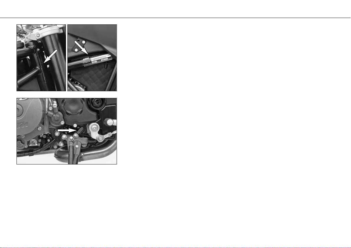
Chassis number, Type label
The chassis number is stamped on the right side of the steering head tube. Enter this number in the field on page no 1.
The type label is located on the right frame tube under the seat.
Engine number, engine type
The engine number and the engine type are stamped into the left side of the engine below
the engine sprocket. Enter this number on page 1.
SERIAL NUMBER LOCATIONS »
6
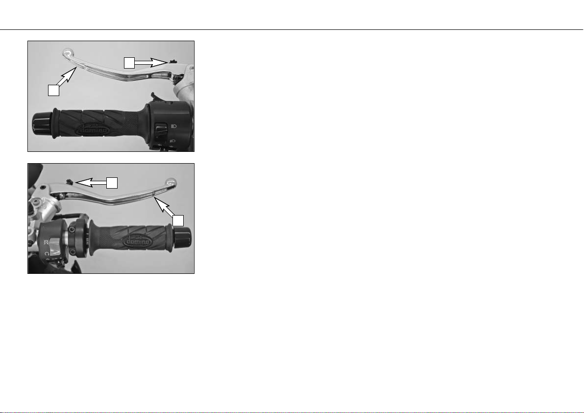
Clutch lever
The clutch lever [1] is fitted on the left hand side of the handle bar. The adjusting screw [A]
is used to change the original position of the clutch lever (see maintenance work on chassis and engine).
The clutch is hydraulically actuated and adjusts itself automatically.
Hand brake lever
The hand brake lever [2] is mounted on the handlebar on the right and actuates the front
wheel brake.The adjusting screw [B] is used to change the original position of the hand brake
lever (see maintenance work on chassis and engine).
OPERATION INSTRUMENTS »
7
B
2
1
A
Multi-functional digital speedometer
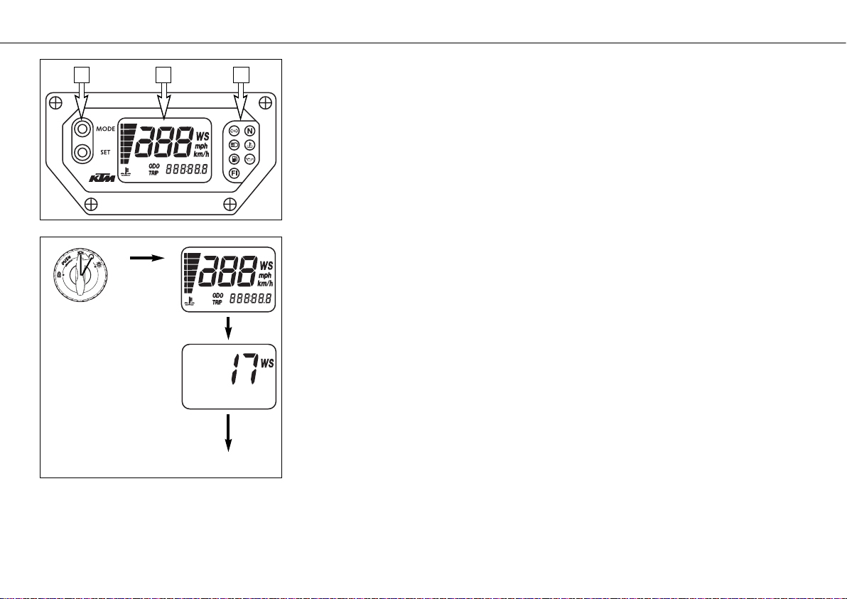
The universal instrument is divided into 3 parts.
Use the MODE and SET [1] button to change the display and the basic settings in the display.
Display [2] shows all of the information that may be of interest to you. 5 display modes can
be selected with the MODE button.
The indicator lamps [3] provide additional information on the motorcycle's running
condition.
Display
TEST
When you switch on the ignition, all of the display elements will light up for 1 second for
the function test.
WS (wheel size)
The display will change and show the diameter of the front wheel in inches for 1 second
(WS = wheel size).
Then the CLOCK mode will be displayed, or the mode that was active when the ignition was
switched off.
OPERATION INSTRUMENTS »
8
1 2 3
TEST
WS
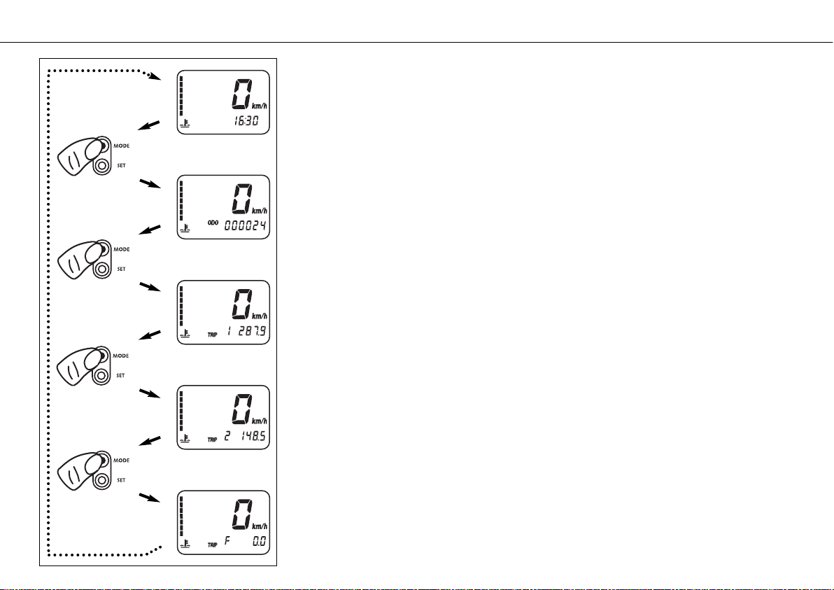
CLOCK
You will recognize the CLOCK display by the blinking dots between the hours and minutes.
It displays the speed, temperature of the cooling liquid and the clock.
To switch to the next display mode, press the MODE button.
ODO
The speed, temperature of the cooling liquid and the total kilometers or miles traveled are
shown in the ODO mode.
To switch to the next display mode, press the MODE button.
TRIP 1
The TRIP 1 mode shows the speed, the temperature of the cooling liquid and the trip odometer 1.
To switch to the next display mode, press the MODE button.
OPERATION INSTRUMENTS »
9
ODO
CLOCK
TRIP 1
TRIP 2
TRIP F
TRIP 2
The TRIP 2 mode shows the speed, the temperature of the cooling liquid and the trip odometer 2.
To switch to the next display mode, press the MODE button.
TRIP F
The TRIP F (fuel) mode shows the speed, the temperature of the cooling liquid and the distance traveled since reaching the low-fuel mark (the low-fuel indicator lamp lights up).
To return to the UHR mode, press the MODE button.
Setting options in the display
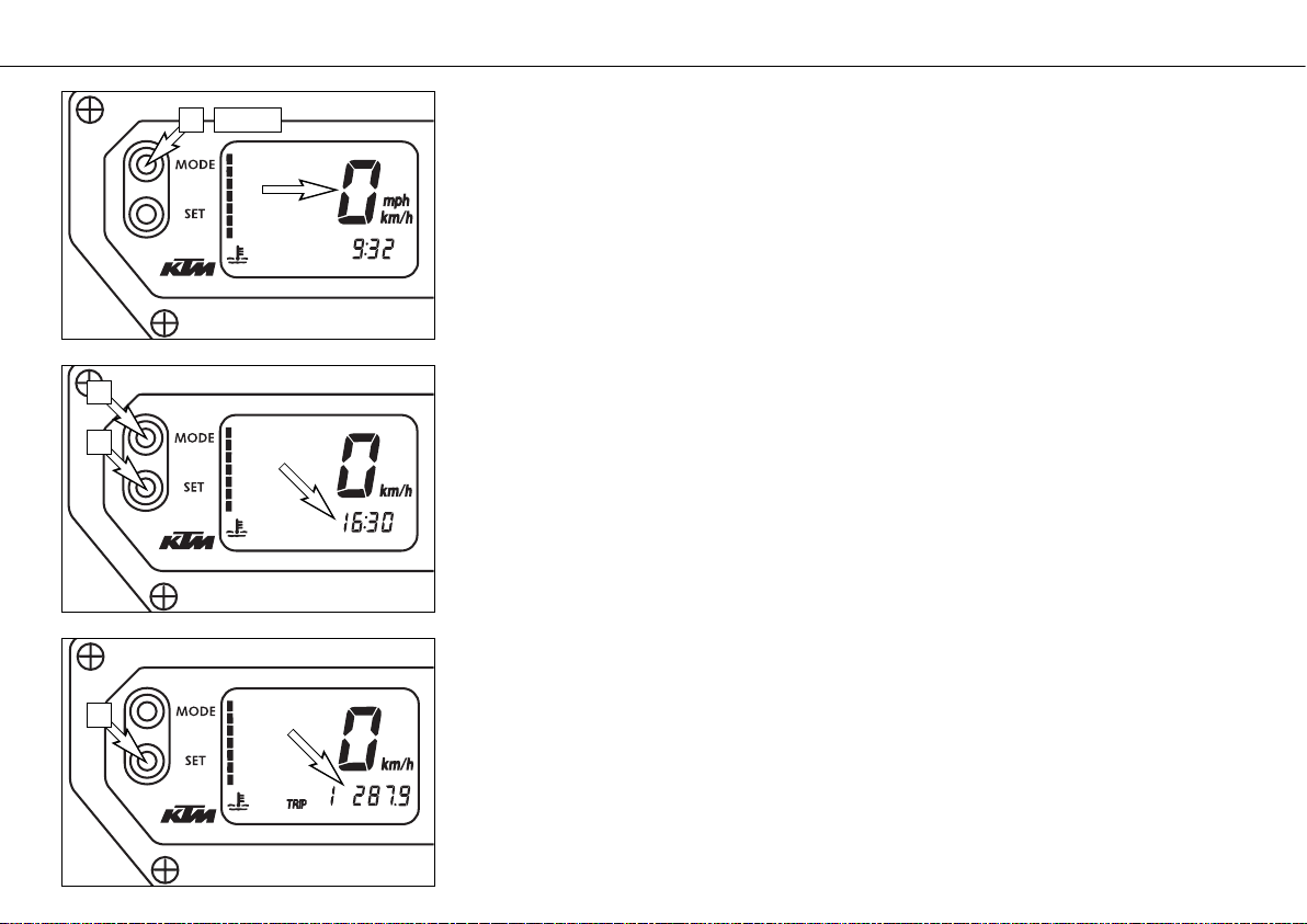
KILOMETERS OR MILES.
You can have the speed and distance shown in kilometers or miles in the display. The display can be adapted to the respective country on long-distance trips.
To switch from kilometers to miles, switch on the ignition and press the MODE [1] button
for approx. 10 seconds. The km/h display will switch to mph. The speed and the stored distances will be converted and displayed in miles.
To return to kilometers, proceed as described above.
CLOCK
Switch on the ignition and change to the CLOCK mode.
Simultaneously press MODE [1] and SET [2]. The numbers on the clock will start to blink.
Use the MODE button to set the hours and the SET button to set the minutes.
The press the MODE and SET buttons simultaneously.
NOTE:
0:00 will be displayed if the clock is not supplied with electricity. This can be caused by a
defective fuse or a fault in the board electric system (see Troubleshooting).
TRIP 1
The trip meter 1 runs continuously and counts up to 999.9. It can be used to measure the
length of a certain route on a trip or the distance between two refueling stops.
To return the trip meter 1 to zero, switch on the ignition, change to the TRIP 1 mode and
press the SET button.
OPERATION INSTRUMENTS »
10
10 sec
1
1
2
2
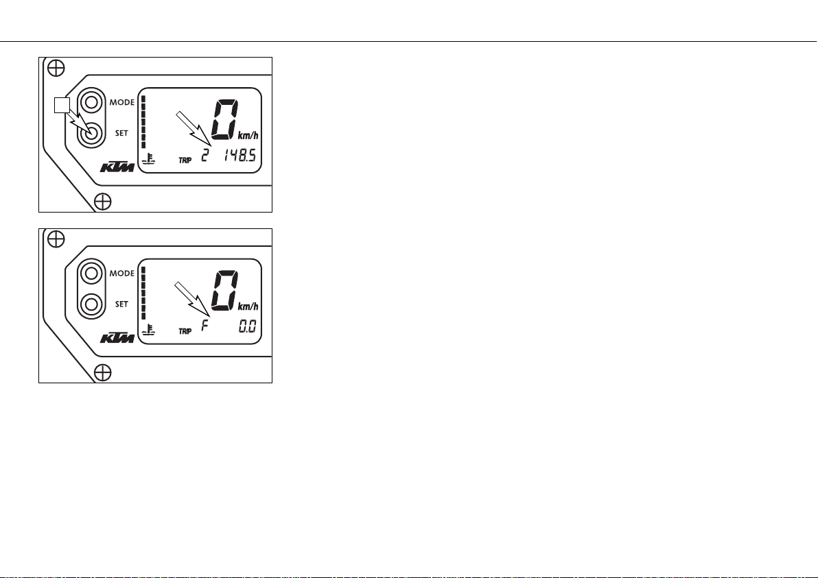
RESETTING TRIP 2
The trip meter 2 runs continuously and counts up to 999.9. It can be used similarly to TRIP
1 or together with a switch available as an accessory (see below) for trips according to a
roadbook.
To return the trip meter 2 to zero, switch on the ignition, change to the TRIP 2 mode and
press the SET button.
TRIP F
When the fuel level reaches the reserve mark, the display will automatically switch to TRIP
F and begin to count (no matter which display mode was active before). At the same time,
the fuel warning lamp will light up. You will still have enough reserve fuel for at least 30
kilometers.
After refueling, it will take approx. 8 minutes for the fuel warning lamp to switch off and for
TRIP F to automatically reset to 0 and return to the previous display mode.
NOTE:
Press the SET key for 2 seconds to immediately turn off the fuel warning lamp.
OPERATION INSTRUMENTS »
11
2
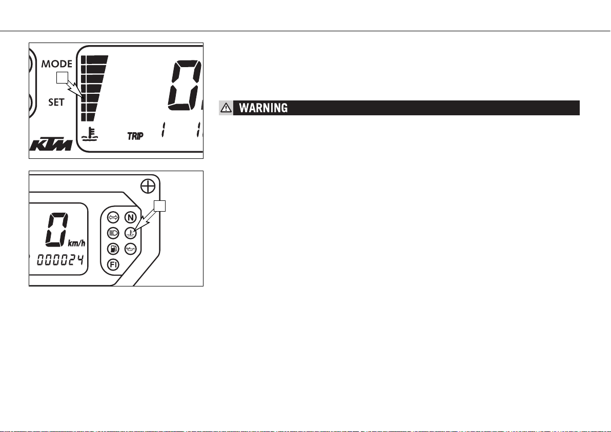
Cooling liquid temperature display
The temperature display [1] is shown in 7 bars. The more bars that light up, the hotter the
cooling liquid. When the lowest bar lights up, the cooling liquid has reached a temperature
of approx. 40°C (104°F). When the upper bar lights up 120°C (248°F), all of the bars will
start to blink and the red warning lamp [2] will light up.
POSSIBLE CAUSES FOR AN INCREASE IN TEMPERATURE, CAUSING THE RED WARNING LIGHT
FOR THE COOLING LIQUID TEMPERATURE TO LIGHT UP:
– DRIVING TOO SLOWLY AND DRIVING WITH A HEAVY LOAD AT HIGH AIR TEMPERATURES
– NOT ENOUGH COOLING LIQUID IN THE SYSTEM
– THE VENTILATOR ON THE LEFT RADIATOR IS NOT RUNNING
– IMPROPER USE OF THE CLUTCH WHEN DRIVING SLOWLY
OPERATION INSTRUMENTS »
12
120°C (248°F)
110°C (230°F)
100°C (212°F)
70°C (158°F)
60°C (140°F)
50°C (122°F)
40°C (104°F)
1
2
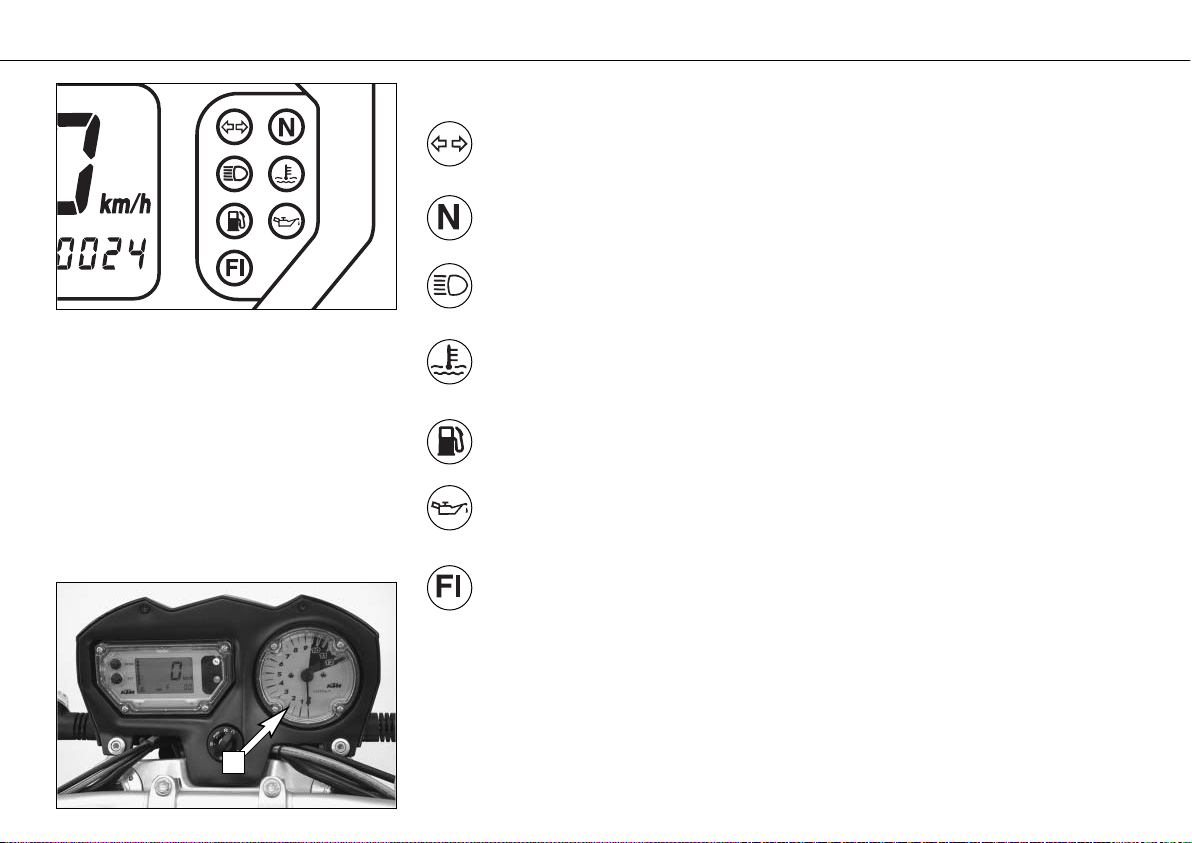
Indicator lamps
The green indicator lamp will blink in the blinker rhythm when the blinker is
switched on.
NOTE: The indicator lamp will blink slower when a blinker is broken.
The green indicator lamp will light up when the gearbox is in an idling position.
The blue indicator lamp will light up when the high beams are switched on.
The red warning light will light up when the cooling liquid has reached a temperature of approx. 120°C (248°F).
The orange warning lamp will light up when the fuel level has reached the reserve mark.
At the same time the display will automatically change to TRIP F (see TRIP F).
The red warning lamp lights up when the ignition is switched on but the engine is
not running. When the engine is started, the warning lamp will go out as soon as the
oil pressure is high enough.
The orange warning lamp (fuel injection) briefly lights up when the ignition is switched
on. It will go out when the gasoline pressure is high enough.
If this warning lamp lights up while driving, a component in the injection system is
defective. The error can be identified by means of a blink code (see Maintenance work).
Tachometer
The tachometer [3] shows the engine speed in revolutions per minute. Do not run the engine
beyond the black mark at 9500 rpm.
The speed limiter will set in at 9600 rpm, drastically reducing the engine power above this
rotational speed.
OPERATION INSTRUMENTS »
13
3
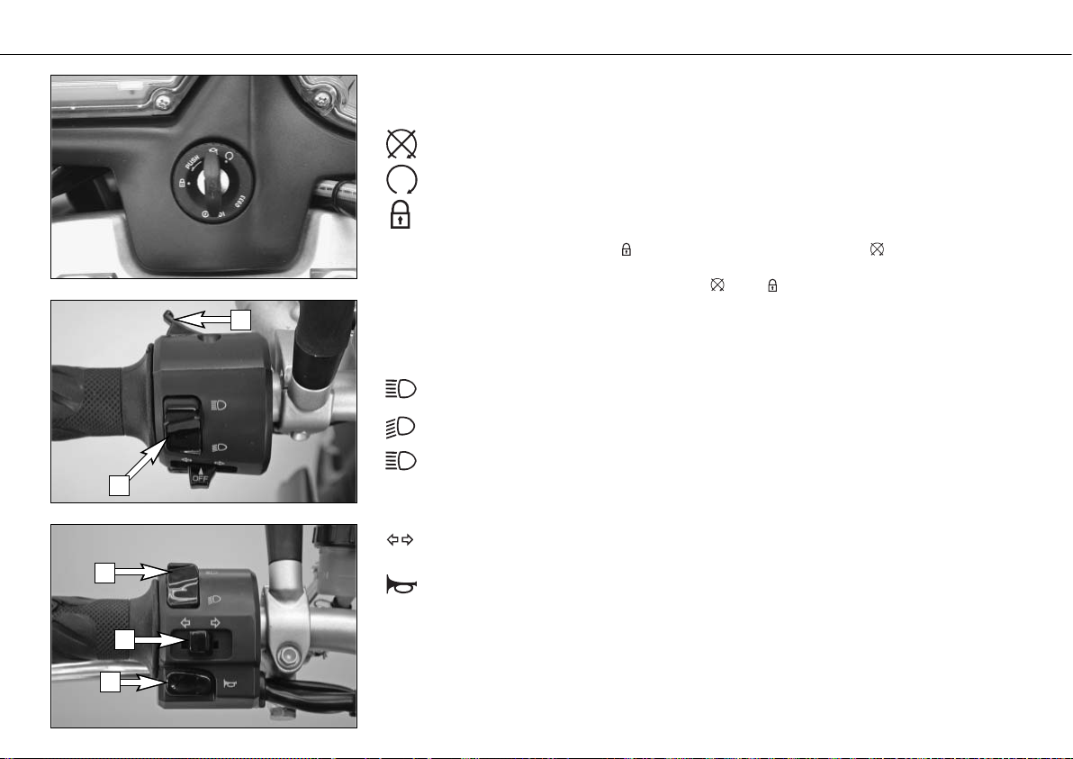
Ignition lock
The ignition lock has 3 switching positions.
Ignition off, (engine can't be started)
Ignition on, (engine can be started)
Ignition off, handlebar blocked
To switch the ignition to position turn the ignition key to position and firmly press it
into the lock. Turn the handlebar to the left, then turn the ignition key to the left.
The ignition key can be withdrawn in position and .
Combination switch
The rocker switch LIGHTS [1] actuates the high beam or low beam.
High-beam light
Low-beam light
The light signal (high beam) is actuated with button [2].
The indicator switch [3] returns to central position after actuation. Press flasher
switch towards switch housing to switch off the flasher.
The horn is sounded with button [4].
OPERATION INSTRUMENTS »
14
2
1
1
3
4
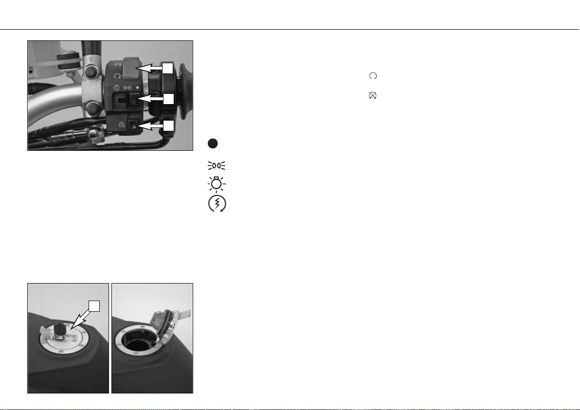
Emergency OFF tip switch, light switch, starter tip switch
The emergency off switch [1] is provided for emergency situations and should not be used
to switch off the engine.
The engine is ready for operation in position (ignition circuit and starter circuit are switched
on).
The engine cannot be started in position (ignition circuit and starter circuit are interrupted).
The light switch [2] has 3 positions:
Light off
Parking light on
Headlight on
Use the starter tip switch [3] to operate the electric starter.
Filler cap
The filler cap [4] can be locked. It is equipped with a tank ventilation system.
To open, insert the ignition key, turn 45° in a clockwise direction and tilt the filler cap back.
After refueling, pull out the ignition key and press down on the filler cap until the lock engages.
OPERATION INSTRUMENTS »
15
1
2
3
4
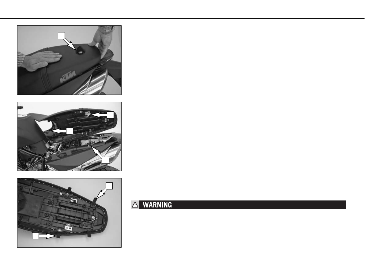
Seat lock, removing the seat
The seat lock [1] can be locked with the ignition key.
To remove the seat, insert the ignition key and turn 90° in a clockwise direction. Lift the
seat in the back while pressing near the holding strap and pull off towards the back.
To mount the seat, place it on the motorcycle and position the hooks [2] on the bottom of
the seat behind the dollies [3] on the subframe. Press down on the seat near the holding
strap while sliding it forwards. The two tabs [4] must hook onto the tank. Turn the ignition
key in the seat lock 90° in a counterclockwise direction and pull off. Check whether the seat
is mounted correctly.
Baggage loops
4 loops [5] are mounted on the bottom of the seat to which small pieces of baggage can be
fastened. Fold the loops towards the outside to make them accessible when the seat is mounted.
BAGGAGE WEIGHT: MAX. 5 KG
OPERATION INSTRUMENTS »
16
1
2
4
3
5
5
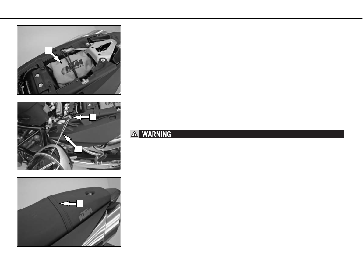
Tool set
The tool set [1] is located in the storage compartment under the seat.
Helmet lock
The steel rope [2] in the tool bag can be used to secure a helmet.
To secure, remove the seat, run the rope through the helmet, attach both ends to the hook
[3] and mount the seat.
THE HELMET LOCK IS PROVIDED TO SECURE THE HELMET TO THE MOTORCYCLE WHEN PARKED.
DO NOT ATTACH THE HELMET OR OTHER OBJECTS TO THE STEEL ROPE WHILE DRIVING. YOU
CAN EASILY LOSE CONTROL OF THE MOTORCYCLE.
Holding strap
The passenger should hold on to the holding strap [4] or the driver while riding.
OPERATION INSTRUMENTS »
17
1
3
2
4
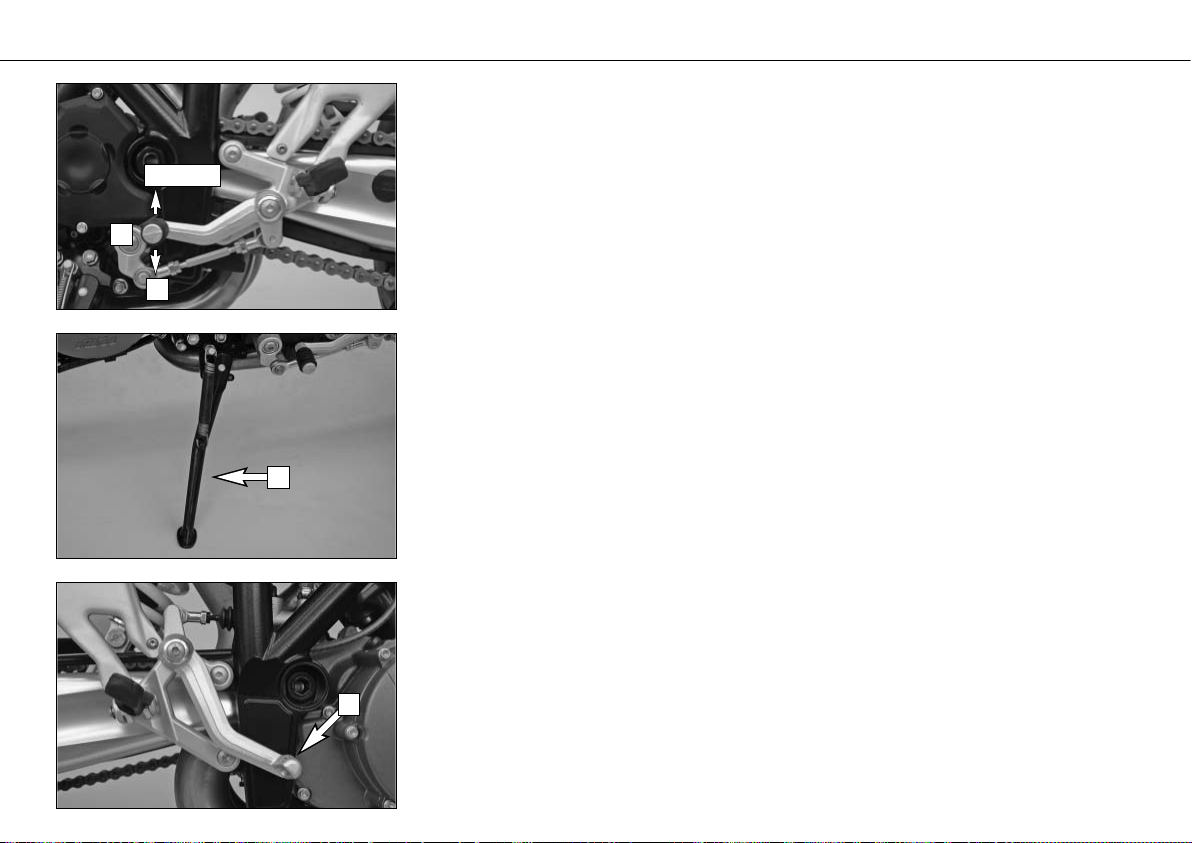
Shift lever
The shift lever is mounted on the left side of the engine. The position of the gears is shown
in the illustration. Neutral, or the idle speed, is located between first and second gear.
The basic position of the shift lever can be adjusted according to your seating position (see
Maintenance work).
Side stand
Fold the side stand [1] forward to the stop with your foot and put the weight of the motorcycle on the stand. Make sure it is standing securely on a firm surface. The side stand is
linked to the safety start system; follow the driving instructions.
Foot brake pedal
The foot brake pedal [2] is located in front of the right footrest. Its basic position can be
adjusted to your seat position (see maintenance work).
OPERATION INSTRUMENTS »
18
1
N
2,3,4,5,6
1
2
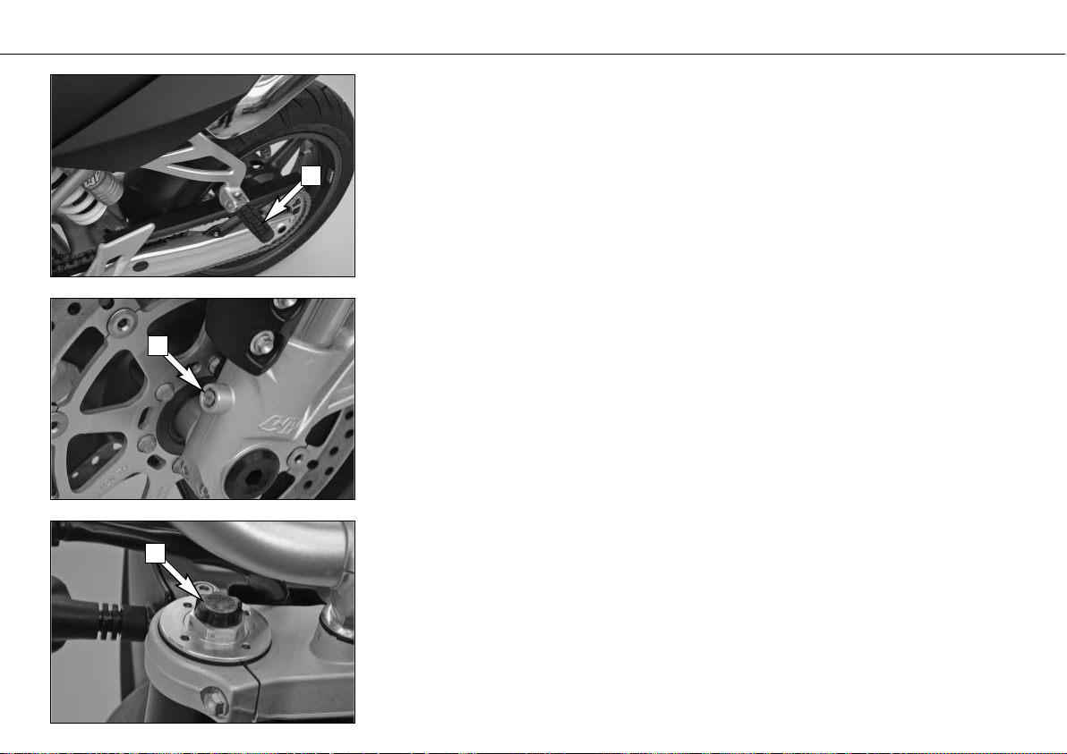
Footrests
The passenger footrests [1] fold up.
Compression damping of fork
The fork's damping action during compression travel (compression damping) can be adjusted.
This allows you adjust the damping behavior to match your driving style and the payload.
The adjusting screws [2] are located on the fork leg axle passage.
More information is provided in the chapter „Adjusting the fork and shock absorber“.
Rebound damping of fork
The fork's damping action during rebound travel (rebound damping) can also be adjusted.
This allows you adjust the damping behavior to match your driving style and the payload.
The adjusting screws [3] are located on the upper end of the fork legs.
More information is provided in the chapter "Adjusting the fork and shock absorber.“
OPERATION INSTRUMENTS »
19
1
2
3
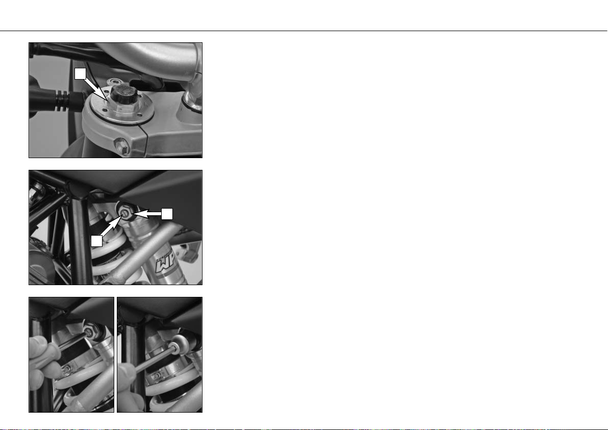
Spring preload of the fork
The fork's preload can be adjusted by means of the adjusting screws [1].
More information is provided in the chapter „Adjusting the fork and shock absorber“.
Damping action during compression of shock absorber
The shock absorber's damping action during compression travel (compression damping) can
be adjusted. This allows you adjust the shock absorber's damping behavior to match your
driving style and the payload.
The damping rate can be adjusted in the low and high-speed range (Dual Compression Control).
The designation low and high-speed refers to the movement of the shock absorber and not
to the motorcycle's driving speed.
The adjusting screw [2] for the low-speed range can be adjusted with a screwdriver.
The adjusting screw [3] for the high-speed range can be adjusted with a 17 mm socket wrench.
More information is provided in the chapter „Adjusting the fork and shock absorber“.
OPERATION INSTRUMENTS »
20
1
2
3
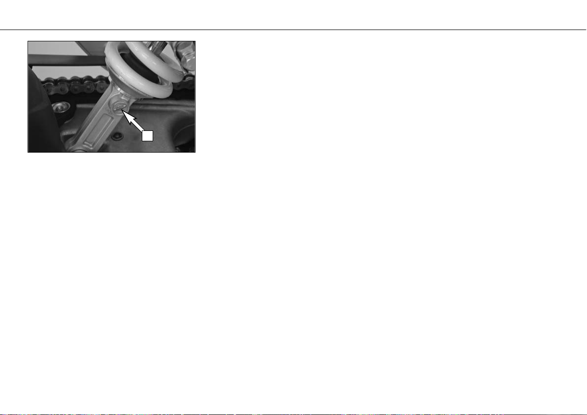
Rebound damping of shock absorber
The shock absorber's damping action during rebound travel (rebound damping) can also be
adjusted. This allows you adjust the damping behavior to match your driving style and the
payload.
The adjusting screw [1] is located on the bottom of the shock absorber.
More information is provided in the chapter "Adjusting the fork and shock absorber.“
OPERATION INSTRUMENTS »
21
1
Instructions for initial operation
– Make sure the work for the „pre-delivery
inspection“ was performed by your authorized KTM workshop. The DELIVERY CERTIFICATE and SERVICE MANUAL will
be handed over when you pick up your
vehicle.
– Read these operating instructions care-
fully before your first ride.
– Enter the chassis, engine and key num-
bers on page 1.
– Familiarize yourself with the operating
elements.
– Adjust the clutch lever, the hand brake
lever, the foot brake lever and the shift
lever in the position that is most convenient for you.
– This motorcycle is equipped with a three-
way catalytic converter. Leaded fuel will
destroy the converter. Always use unleaded
fuel.
– Get used to handling the motorcycle on
an empty parking lot, before starting on
a longer drive. Also try to drive as slowly
as possible and in standing position, to
improve your feeling for the vehicle.
– You may only be accompanied by a pas-
senger if your motorcycle is fitted and registered for such purposes. The passenger
must hold on to the supporting strap or
the driver and keep his feet on the passenger footrests throughout the ride.
–
Hold the handlebars with both hands
and leave your feet on the foot rests while
driving.
– Remove your foot from the foot brake
lever when you are not braking. If the foot
brake lever is not released the brake pads
rub continuously and the braking system
is overheated.
– Do not make any alterations to the motor-
cycle and always use ORIGINAL KTM
SPARE PARTS. Spare parts from other
manufacturers can impair the safety of
the motorcycle.
– New tires have a smooth surface, which
means that they must be run in to achieve
full grip. For this purpose, ride the motorcycle carefully at moderate speed during
the first 200 kilometers with new tires,
tilting the vehicle at different angles so
that all sections are properly roughened.
Tires will not display their full grip characteristics until they are properly run in.
– Motorcycles are sensitive to changes in
the weight distribution. Read the section
on „Accessories and payload“ when carrying luggage.
– Pay attention to running-in procedure.
Running in the LC8 engine
Even finely machined surfaces of engine
parts have rougher surfaces than parts that
slide on each other for a long time. Therefore,
every engine must be run in. For this reason,
do not demand maximum performance from
the engine for the first 1000 kilometers (620
miles). The vehicle must be run in at low,
changing performance level for the first 1000
km (620 miles). The maximum number of
revolutions per minute must not go exceed
6500 rpm. Once you have run your engine
in for 1000 km, you may push it to its 9500
rpm limit , i.e. up to the black zone indicated
in the tachometer. Exceeding the above listed
rotations as well as pushing high rpm when
the engine is cold will have an adverse effect
on the life of your engine.
– WEAR SUITABLE CLOTHING WHEN DRIV-
ING A MOTORCYCLE. CLEVER KTM DRIVERS ALWAYS WEAR A HELMET, BOOTS,
GLOVES AND A JACKET, REGARDLESS OF
WHETHER DRIVING ALL DAY OR JUST FOR
A SHORT TRIP. THE PROTECTIVE CLOTHING
SHOULD BE BRIGHTLY COLORED SO THAT
OTHER VEHICLE CAN SEE YOU AS EARLY AS
POSSIBLE. YOUR PASSENGER WILL ALSO
NEED SUITABLE PROTECTIVE CLOTHING.
– DO NOT DRIVE AFTER HAVING CONSUMED
ALCOHOL.
– ALWAYS TURN ON THE LIGHT TO MAKE
SURE THAT OTHER DRIVERS BECOME
AWARE OF YOU AS EARLY AS POSSIBLE.
– DRIVE AT A MODERATE SPEED FOR THE
FIRST FEW KILOMETERS OF EACH TRIP TO
ALLOW THE TIRES TO REACH THE NECESSARY OPERATING TEMPERATURE. MAXIMUM
ROAD GRIP IS ASSURED WHEN THE TIRES
ARE WARM.
– THE FRONT AND REAR WHEEL ARE
ALLOWED TO BE FITTED ONLY WITH TIRES
THAT HAVE THE SAME PROFILE TYPE.
GENERAL TIPS AND WARNINGS FOR STARTING THE MOTORCYCLE »
22
– THE TIRES MUST BE DESIGNED FOR A
SPEED OF OVER 240 KPH (SPEED SYMBOL
ZR) AND MUST BE RELEASED BY KTM.
– NEW TIRES HAVE A SMOOTH SURFACE,
WHICH MEANS THAT THEY MUST BE RUN
IN TO ACHIEVE FULL GRIP. FOR THIS PURPOSE, RIDE THE MOTORCYCLE CAREFULLY
AT MODERATE SPEED DURING THE FIRST
200 KILOMETERS WITH NEW TIRES, TILTING THE VEHICLE AT DIFFERENT ANGLES
SO THAT ALL SECTIONS ARE PROPERLY
ROUGHENED. TIRES WILL NOT DISPLAY
THEIR FULL GRIP CHARACTERISTICS UNTIL
THEY ARE PROPERLY RUN IN.
– WHEELS WITH A DIFFERENT RIM DIAMETER
OR OTHER RIM WIDTH MAY NOT BE
MOUNTED OTHERWISE THE VEHICLE HANDLING WILL NO LONGER BE SAFE.
– OBSERVE THE TRAFFIC REGULATIONS,
DRIVE DEFENSIVELY AND TRYING TO LOOK
AHEAD AS FAR AS POSSIBLE SO THAT ANY
HAZARDS CAN BE RECOGNIZED AS EARLY
AS POSSIBLE.
– THE FASTER YOU DRIVE, THE MORE SEN-
SITIVE YOUR MOTORCYCLE WILL BE TO
CROSSWIND AND CHANGING ROAD CONDITIONS. YOUR MOTORCYCLE CAN EASILY GO
OUT OF CONTROL AT HIGH SPEEDS.
– CHOOSE YOUR DRIVING SPEED ACCORDING
TO THE CONDITIONS AND YOUR DRIVING
SKILLS.
– DRIVE CAREFULLY ON UNKNOWN ROADS OR
ON UNFAMILIAR TRIALS.
– RENEW THE VIZOR ON YOUR HELMET ON
TIME SO AS TO ENSURE OPTIMUM VISION
IN ANY SITUATION. WHEN LIGHT SHINES
DIRECTLY ON SCRATCHED VISOR, THE OPERATOR WILL BE BLINDED.
– NEVER LEAVE YOUR MOTORCYCLE WITHOUT
SUPERVISION IF THE ENGINE IS RUNNING.
Accessories and payload
Accessory parts and baggage can significantly decrease a motorcycle's driving stability. Please observe the following warnings.
– NEVER DRIVE FASTER THAN 130 KPH (80
MPH) IF YOU HAVE MOUNTED ACCESSORY
PARTS ON YOUR MOTORCYCLE. ACCESSORY
PARTS CAN SIGNIFICANTLY IMPAIR THE
MOTORCYCLE'S HANDLING, ESPECIALLY IN
THE MAXIMUM SPEED RANGE.
– NEVER DRIVE FASTER THAN 130 KPH (80
MPH) IF YOUR MOTORCYCLE IS LOADED
WITH CASES OR OTHER BAGGAGE. THEY
WILL IMPAIR THE MOTORCYCLE'S HANDLING AT HIGHER SPEEDS AND CAN EASILY CAUSE IT TO GO OUT OF CONTROL
– IF YOU HAVE CASES MOUNTED, DO NOT
EXCEED THE MANUFACTURER'S RECOMMENDED MAXIMUM PAYLOAD.
– FOUR LOOPS ARE PROVIDED ON THE BOT-
TOM OF THE SEAT TO ATTACH YOUR LUGGAGE. MAKE SURE YOUR LUGGAGE DOES
NOT EXTEND BEYOND THE SILENCER, OTHERWISE IT MAY BECOME SINGED FROM
THE HEAT.
– MAKE SURE YOUR LUGGAGE DOES NOT
COVER THE TAIL LIGHT.
– BAGGAGE MUST BE SECURELY AND ADE-
QUATELY FASTENEND; LOOSE BAGGAGE
WILL SIGNIFICANTLY IMPAIR DRIVING
SAFETY.
– A HIGH PAYLOAD WILL CHANGE THE MOTOR-
CYCLE'S HANDLING AND CONSIDERABLY
INCREASE THE BRAKING DISTANCE; ADAPT
YOUR DRIVING SPEED ACCORDINGLY.
– NEVER EXCEED THE MAXIMUM PERMISSI-
BLE LADEN WEIGHT AND THE AXLE
WEIGHTS. THE MAXIMUM PERMISSIBLE
LADEN WEIGHT IS MADE UP OF THE FOLLOWING COMPONENTS:
– MOTORCYCLE READY FOR OPERATION
AND TANK FULL
– LUGGAGE
– DRIVER AND PASSENGER WITH PROTEC-
TIVE CLOTHING AND HELMET
GENERAL TIPS AND WARNINGS FOR STARTING THE MOTORCYCLE »
23
Check the following before each start
When you start, the motorcycle must be in perfect mechanical condition. For safety reasons,
you should make a habit of performing an overall check of your motorcycle before each start.
The following checks should be performed:
1 FUEL
Check the fuel quantity in the tanks.
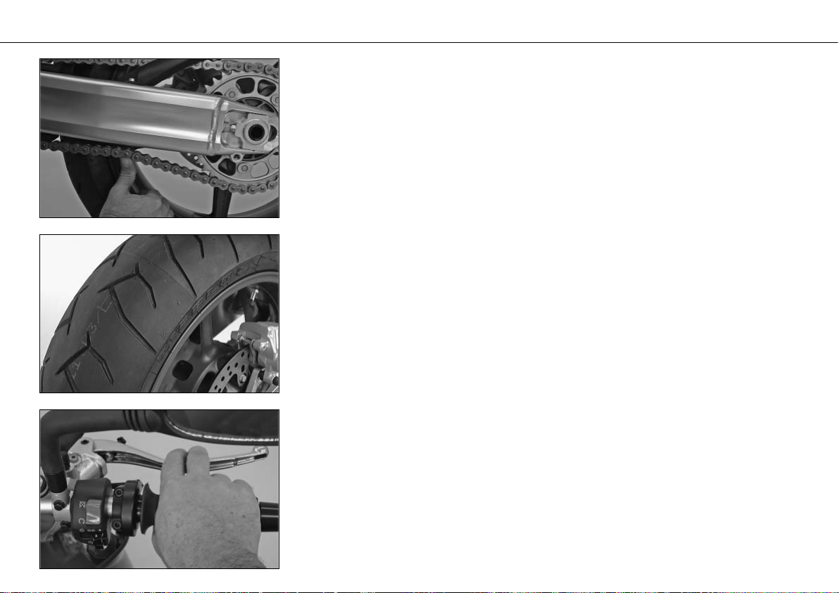
2 CHAIN
Check the tension and condition of the chain.
A loose chain can fall off the sprockets and a worn-out chain can tear. In both cases this
can damage other motorcycle components and cause the motorcycle to go out of control. A chain that is too tight or not greased will cause unnecessary wear to the chain
and sprockets.
3 TIRES
Check for damaged tires. Tires showing cuts or dents must be replaced. The tread depth
must comply with the legal regulations. Also check the air pressure. Insufficient tread
and incorrect air pressure deteriorate the driving performance.
4 BRAKES
Check correct functioning of the braking system. Check for sufficient brake fluid in the
reservoir. The reservoirs have been designed in such a way that brake fluid does not need
to be refilled even when the brake pads are worn. If the level of brake fluid falls below
the minimum value, this indicates a leak in the braking system or completely worn out
brake pads. Arrange for the braking system to be checked by a KTM specialist, as complete failure of the braking system can be avoided.
Also check the state of the brake hose and the thickness of the brake linings.
Check free travel at hand brake lever and foot brake lever.
5 CABLES
Check the throttle cable for correct adjustment and smooth operation.
DRIVING INSTRUCTIONS »
24
6 COOLING FLUID
Check the level of cooling fluid when the engine is cold.
7 ELECTRICAL SYSTEM
Start the engine and check the headlight, tail lamp, brake light, turn signals, indicator
lamps, horn and emergency-off switch for proper functioning.
8 CHECK OIL LEVEL
Insufficient oil results in premature wear and consequently to engine damage.
9 BAGGAGE, PAYLOAD
Never exceed the maximum total weight (380 kg, 838 lbs) and the motorcycle's wheel
loads. The maximum total weight is comprised of:
– the motorcycle in a running condition and refueled (195 kg, 430 lbs)
– the baggage and accessories
– the driver and passenger with protective gear and helmet
Adjust the tire inflation pressure as well as the preload and damping properties of the
fork and shock absorber to the total weight.
Make sure your luggage is correctly fastened before you drive off.
10 REAR MIRROR
Sit on the motorcycle and check the adjustment of the rear mirror.
DRIVING INSTRUCTIONS »
25
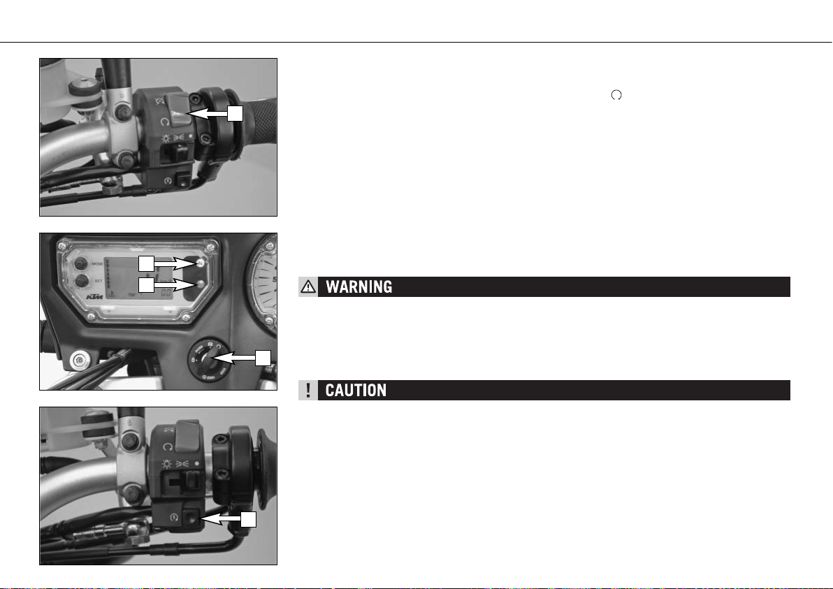
Starting the engine
1 Switch on emergency OFF switch [1].
2 Switch on ignition (turn ignition key [2] into position ).
NOTE:
You will hear the operation of the fuel pump for approx. 2 seconds after switching on
the ignition. The FI indicator lamp will also light up during this time and the engine
should not be started.
3 Switch transmission to idle (green indicator lamp N [3] lights up).
4 Do not accelerate; operate starter button [5].
NOTE:
If you accelerate during the starting process you will hear a loud, metallic
sound caused by the torque limiter. The torque limiter protects the
components in the starter drive from being damaged.
5 The oil pressure warning lamp [4] should go out as soon as the engine is running.
6 Take the load off the side stand and fold the side stand all the way up.
– DO NOT START THE ENGINE AND ALLOW IT TO IDLE IN A CLOSED ROOM. EXHAUST FUMES
ARE POISONOUS AND CAN CAUSE LOSS OF CONSCIOUSNESS AND DEATH. ALWAYS PROVIDE
ADEQUATE VENTILATION WHILE THE ENGINE IS RUNNING.
– NEVER OPERATE THE MOTORCYCLE WITH A RUN-DOWN BATTERY OR WITHOUT THE BATTERY.
THIS CAN DAMAGE THE ELECTRONIC COMPONENTS OR SAFETY EQUIPMENT IN EITHER CASEAND THE MOTORCYCLE WILL NO LONGER BE ROADWORTHY.
– IF YOU ACCELERATE WHILE STARTING, THE ENGINE MANAGEMENT WILL NOT INJECT ANY
FUEL AND THE ENGINE WILL NOT START. DO NOT ACCELERATE WHILE STARTING!
– IF THE OIL PRESSURE WARNING LAMP DOES NOT GO OUT AS SOON AS THE ENGINE IS RUN-
NING, IMMEDIATELY SWITCH OFF THE ENGINE. IF THE ENGINE IS NOT SWITCHED OFF,
ENGINE DAMAGE WILL OCCUR WITHIN A SHORT PERIOD OF TIME. CHECK THE ENGINE OIL
LEVEL OR CONTACT A KTM WORKSHOP.
– MAXIMUM PERIOD FOR CONTINUOUS STARTING: 5 SECONDS. WAIT AT LEAST
5 SECONDS BEFORE TRYING AGAIN.
– DON’T RIDE YOUR MOTORCYCLE WITH FULL LOAD AND DON’T REV ENGINE WHEN COLD.
BECAUSE THE PISTON IS WARMING UP FASTER THAN THE WATER COOLED CYLINDER, IT CAN
CAUSE ENGINE DAMAGE. ALWAYS LET THE ENGINE WARM UP BEFORE AND REFRAIN FROM
DRIVING WITH FULL LOAD UNTIL THE ENGINE IS WARM.
DRIVING INSTRUCTIONS »
26
1
3
4
2
5
 Loading...