

Page 1
OWNER'S MANUAL 2013
990 Supermoto T AUS/UK
990 Supermoto T EU
990 Supermoto T FR
Art. no. 3211957en
Page 2

Page 3
DEAR KTM CUSTOMER 1
DEARKTM CUSTOMER
Congratulations on your decision to purchase a KTM motorcycle. You are now the owner of a state-of-the-art sports motorcycle that will
give you enormous pleasure if you service and maintain it accordingly.
We wish you a lot of enjoyment in riding this vehicle.
Please enter the serial numbers of your vehicle below.
Chassis number/type label Dealer's stamp
Engine number ( p. 21)
Key number ( p. 21)
The owner's manual contained the latest information for this model at the time of going to print. Minor differences due to developments in
design cannot be ruled out completely.
All specifications are non-binding. KTM Sportmotorcycle AG specifically reserves the right to modify or delete technical specifications,
prices, colors, forms, materials, services, designs, equipment, etc., without prior notice and without specifying reasons, to adapt these to
local conditions, as well as to stop production of a particular model without prior notice. KTM accepts no liability for delivery options, deviations from illustrations and descriptions, as well as printing and other errors. The models portrayed partly contain special equipment that
does not belong to the regular scope of delivery.
© 2012 KTM-Sportmotorcycle AG, Mattighofen Austria
All rights reserved
Reproduction, even in part, as well as copying of all kinds, is permitted only with the express written permission of the copyright owner.
Page 4

DEAR KTM CUSTOMER 2
ISO 9001(12 100 6061)
According to the international quality management standard ISO 9001, KTM uses quality assurance processes that lead to
the maximum possible quality of the products.
Issued by: TÜV Management Service
KTM-Sportmotorcycle AG
5230 Mattighofen, Austria
Page 5

TABLE OF CONTENTS 3
TABLEOF CONTENTS
1 MEANS OF REPRESENTATION ........................................ 7
1.1 Symbols used ...................................................... 7
1.2 Formats used....................................................... 7
2 SAFETY ADVICE.............................................................. 8
2.1 Use definition - intended use ................................ 8
2.2 Safety advice ....................................................... 8
2.3 Degrees of risk and symbols.................................. 9
2.4 Tampering warning............................................... 9
2.5 Safe operation ................................................... 10
2.6 Protective clothing ............................................. 11
2.7 Work rules ......................................................... 11
2.8 Environment...................................................... 11
2.9 Owner's Manual ................................................. 12
3 IMPORTANT NOTES...................................................... 13
3.1 Guarantee, warranty ........................................... 13
3.2 Operating substances ......................................... 13
3.3 Spare parts, accessories ..................................... 13
3.4 Service ............................................................. 13
3.5 Figures ............................................................. 14
3.6 Customer service................................................ 14
4 VIEW OF VEHICLE ........................................................ 16
4.1 View of vehicle, front left side (example) .............. 16
4.2 View of vehicle, rear right side (example).............. 18
5 SERIAL NUMBERS ....................................................... 20
5.1 Chassis number ................................................. 20
5.2 Type label ......................................................... 20
5.3 Key number....................................................... 21
5.4 Engine number .................................................. 21
5.5 Fork part number ............................................... 22
5.6 Shock absorber part number ............................... 22
6 CONTROLS................................................................... 23
6.1 Clutch lever ....................................................... 23
6.2 Hand brake lever................................................ 23
6.3 Throttle grip ...................................................... 24
6.4 Horn button....................................................... 24
6.5 Light switch ...................................................... 25
6.6 Headlight flasher switch ..................................... 25
6.7 Turn signal switch.............................................. 26
6.8 Emergency OFF switch ....................................... 26
6.9 Electric starter button......................................... 27
6.10 Ignition/steering lock.......................................... 27
6.11 Immobilizer....................................................... 28
6.12 Combination instrument ..................................... 28
6.12.1 Overview ....................................................... 28
6.12.2 Function buttons ........................................... 29
6.12.3 Tachometer................................................... 29
6.12.4 indicator lamps.............................................. 30
6.12.5 Display ......................................................... 31
6.12.6 Speed display................................................ 32
6.12.7 Setting kilometers or miles ............................. 32
6.12.8 Time............................................................. 33
6.12.9 Setting the clock ........................................... 33
6.12.10 ODO display .................................................. 34
6.12.11 Setting/resetting display TRIP 1 ...................... 34
6.12.12 Setting/resetting display TRIP 2 ...................... 35
6.12.13 TRIP F display............................................... 36
6.12.14 Ambient temperature indicator........................ 36
6.12.15 Setting the temperature units.......................... 36
Page 6

TABLE OF CONTENTS 4
6.12.16 Warning of icy roads....................................... 37
6.12.17 Coolant temperature indicator ......................... 38
6.13 Hazard warning flasher switch/hazard warning
flasher .............................................................. 38
6.14 Socket for electrical accessories .......................... 39
6.15 Opening the filler cap......................................... 39
6.16 Closing the filler cap .......................................... 40
6.17 Seat lock........................................................... 41
6.18 Tool set............................................................. 41
6.19 Handrails .......................................................... 42
6.20 Helmet lock....................................................... 42
6.21 Luggage rack plate............................................. 43
6.22 Passenger footrests ............................................ 43
6.23 Shift lever ......................................................... 44
6.24 Foot brake lever ................................................. 45
6.25 Side stand......................................................... 45
7 PREPARING FOR USE................................................... 46
7.1 Information on first use ...................................... 46
7.2 Running in the engine ........................................ 47
7.3 Loading the vehicle............................................ 47
8 RIDING INSTRUCTIONS................................................ 50
8.1 Checks and maintenance measures when
preparing for use................................................ 50
8.2 Starting............................................................. 51
8.3 Starting off........................................................ 53
8.4 Shifting, riding .................................................. 53
8.5 Braking............................................................. 56
8.6 Stopping, parking............................................... 58
8.7 Transport .......................................................... 59
8.8 Refueling .......................................................... 60
9 SERVICE SCHEDULE .................................................... 62
9.1 Service schedule................................................ 62
10 TUNING THE CHASSIS ................................................. 65
10.1 Fork/shock absorber ........................................... 65
10.2 Adjusting the compression damping of the fork..... 65
10.3 Adjusting the rebound damping of the fork........... 66
10.4 Adjusting the spring preload of the fork................ 67
10.5 Compression damping of the shock absorber......... 69
10.6 Adjusting the low-speed compression damping of
the shock absorber............................................. 69
10.7 Adjusting the high-speed compression damping
of the shock absorber ......................................... 70
10.8 Adjusting the rebound damping of the shock
absorber............................................................ 71
10.9 Adjusting the spring preload of the shock
absorber............................................................ 72
11 SERVICE WORK ON THE CHASSIS................................. 75
11.1 Raising the motorcycle with the rear wheel
stand ................................................................ 75
11.2 Taking the motorcycle off of the rear wheel
stand ................................................................ 75
11.3 Raising the motorcycle with the front wheel
stand ................................................................ 76
11.4 Taking the motorcycle off of the front wheel
stand ................................................................ 76
11.5 Bleeding the fork legs......................................... 77
11.6 Removing the seat ............................................. 77
11.7 Mounting the seat.............................................. 78
11.8 Reinstalling the fuel tank.................................... 78
Page 7

TABLE OF CONTENTS 5
11.9 Positioning the fuel tank..................................... 79
11.10 Mounting the helmet lock on the vehicle .............. 80
11.11 Removing the mask spoiler ................................. 81
11.12 Installing the mask spoiler .................................. 83
11.13 Checking the chain for dirt.................................. 84
11.14 Cleaning the chain ............................................. 84
11.15 Checking the chain tension ................................. 86
11.16 Adjusting the chain tension................................. 87
11.17 Checking the chain, rear sprocket, engine
sprocket and chain guide .................................... 89
11.18 Adjusting the basic position of the clutch lever ..... 92
11.19 Checking/rectifying the fluid level of the
hydraulic clutch................................................. 92
12 BRAKES....................................................................... 94
12.1 ABS/antilock brake system.................................. 94
12.2 Adjusting the basic position of the hand brake
lever ................................................................. 95
12.3 Checking the front brake discs ............................ 95
12.4 Checking the front brake fluid level ..................... 96
12.5 Adding front brake fluid x................................. 97
12.6 Checking the front brake linings .......................... 98
12.7 Checking the free travel of the foot brake lever...... 99
12.8 Adjusting the basic position of the foot brake
lever ............................................................... 100
12.9 Checking the rear brake disc ............................. 101
12.10 Checking the rear brake fluid level..................... 101
12.11 Adding rear brake fluid x................................ 102
12.12 Checking the rear brake linings ......................... 104
13 WHEELS, TIRES ......................................................... 106
13.1 Removing the front wheel x ............................ 106
13.2 Installing the front wheel x............................. 107
13.3 Removing the rear wheel x.............................. 109
13.4 Installing the rear wheel x .............................. 111
13.5 Checking the rear hub rubber dampers x.......... 113
13.6 Checking the tire condition ............................... 114
13.7 Checking the tire air pressure............................ 115
14 ELECTRICAL SYSTEM ................................................. 117
14.1 Removing the battery x .................................. 117
14.2 Installing the battery x ................................... 119
14.3 Recharging the battery x ................................ 120
14.4 Changing the main fuse .................................... 122
14.5 Changing the ABS fuses ................................... 124
14.6 Changing the fuses of individual power
consumers....................................................... 125
14.7 Changing the headlight bulb ............................. 127
14.8 Changing the parking light bulb......................... 129
14.9 Changing the turn signal bulb ........................... 131
14.10 Changing the brake light bulb ........................... 131
14.11 Changing the tail light bulbs ............................. 136
14.12 Changing the license plate lamp........................ 141
14.13 Checking the headlight setting .......................... 143
14.14 Adjusting the headlight range............................ 143
14.15 Activating/deactivating the ignition key .............. 144
15 COOLING SYSTEM ...................................................... 149
15.1 Cooling system ................................................ 149
15.2 Checking the antifreeze and coolant level ........... 149
Page 8

TABLE OF CONTENTS 6
15.3 Checking the coolant level in the compensating
tank................................................................ 152
15.4 Draining the coolant x.................................... 153
15.5 Filling/bleeding the cooling system x ............... 154
16 TUNING THE ENGINE................................................. 157
16.1 Checking the play in the throttle cable............... 157
16.2 Adjusting the play in the throttle cable x.......... 158
16.3 Plug-in connection, ignition timing map ............. 158
16.4 Adjusting the ignition curve to the fuel quality .... 159
16.5 Checking the basic position of the shift lever ...... 160
16.6 Adjusting the basic position of the shift
lever x .......................................................... 160
17 SERVICE WORK ON THE ENGINE ................................ 162
17.1 Checking the engine oil level............................. 162
17.2 Changing the engine oil and filter, cleaning the
oil screens x.................................................. 163
17.3 Draining the engine oil and filter, cleaning the
oil screens x.................................................. 163
17.4 Filling up with engine oil x ............................. 168
17.5 Adding engine oil............................................. 169
18 CLEANING, CARE ....................................................... 170
18.1 Cleaning motorcycle ......................................... 170
18.2 Checks and maintenance measures for winter
operation......................................................... 172
19 STORAGE................................................................... 174
19.1 Storage ........................................................... 174
19.2 Preparing for use after storage........................... 176
20 TROUBLESHOOTING .................................................. 177
21 IMMOBILIZER BLINK CODE ........................................ 180
22 ENGINE CONTROL BLINK CODE.................................. 182
23 TECHNICAL DATA....................................................... 188
23.1 Engine............................................................ 188
23.2 Engine tightening torques................................. 189
23.3 Capacities ....................................................... 192
23.3.1 Engine oil ................................................... 192
23.3.2 Coolant....................................................... 192
23.3.3 Fuel ........................................................... 193
23.4 Chassis ........................................................... 193
23.5 Electrical system.............................................. 194
23.6 Tires............................................................... 195
23.7 Fork................................................................ 195
23.8 Shock absorber ................................................ 196
23.9 Chassis tightening torques ................................ 198
24 SUBSTANCES ............................................................ 202
25 AUXILIARY SUBSTANCES ........................................... 206
26 STANDARDS .............................................................. 209
INDEX ............................................................................... 210
Page 9
1 MEANS OF REPRESENTATION 7
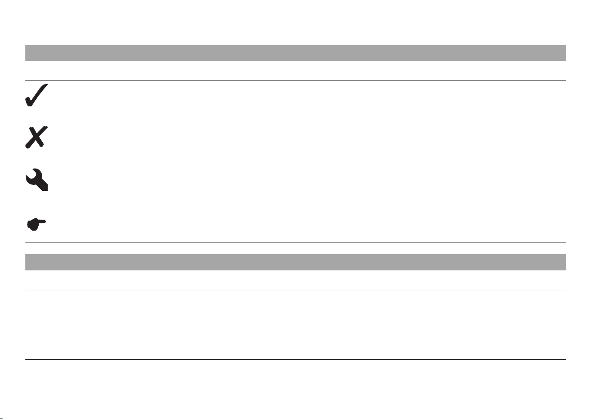
1.1 Symbols used
The meaning of specific symbols is described below.
Indicates an expected reaction (e.g. of a work step or a function).
Indicates an unexpected reaction (e.g. of a work step or a function).
All work marked with this symbol requires specialist knowledge and technical understanding. In the interest of your
own safety, have these jobs performed by an authorized KTM workshop. There, your motorcycle will be optimally
cared for by specially trained experts using the specialist tools required.
Indicates a page reference (more information is provided on the specified page).
1.2 Formats used
The typographical formats used in this document are explained below.
Specific name Identifies a proprietary name.
®
Name
Brand™ Identifies a brand available on the open market.
Identifies a protected name.
Page 10
2 SAFETY ADVICE 8
2.1 Use definition - intended use
KTM sport motorcycles are designed and constructed to meet the normal demands of regular road operation but not for use on race
courses or offroad.
Info
The motorcycle is only authorized for operation on public roads in the homologated version.
2.2 Safety advice
A number of safety instructions need to be followed to operate the vehicle safely. Therefore, read this manual carefully. The safety instructions are highlighted in the text and are referred to at the relevant passages.
Info
The vehicle has various information and warning labels at prominent locations. Do not remove information/warning labels. If they
are missing, you or others may not recognize dangers and may therefore be injured.
Page 11
2 SAFETY ADVICE 9
2.3 Degrees of risk and symbols
Danger
Identifies a danger that will immediately and invariably lead to fatal or serious permanent injury if the appropriate measures are not
taken.
Warning
Identifies a danger that is likely to lead to fatal or serious injury if the appropriate measures are not taken.
Caution
Identifies a danger that may lead to minor injuries if the appropriate measures are not taken.
Note
Identifies a danger that will lead to considerable machine and material damage if the appropriate measures are not taken.
Warning
Identifies a danger that will lead to environmental damage if the appropriate measures are not taken.
2.4 Tampering warning
Tampering with the noise control system is prohibited. Federal law prohibits the following acts or the causing thereof:
1 The removal or rendering inoperative by any person other than for purposes of maintenance, repair, or replacement, of any device or
element of design incorporated into any new vehicle for the purpose of noise control prior to its sale or delivery to the ultimate purchaser or while it is in use, or
2 the use of the vehicle after such device or element of design has been removed or rendered inoperative by any person.
Among those acts presumed to constitute tampering are the acts listed below:
Page 12
2 SAFETY ADVICE 10
1 Removal or puncturing of the main silencer, baffles, header pipes or any other components which conduct exhaust gases.
2 Removal or puncturing of any part of the intake system.
3 Lack of proper maintenance.
4 Replacing any moving part of the vehicle, or parts of the exhaust or intake system, with parts other than those specified by the manu-
facturer.
2.5 Safe operation
Danger
Danger of accidents Danger arising from the rider's judgement being impaired.
– Do not operate the vehicle while under the influence of alcohol, drugs and certain medications or physically or mentally
impaired.
Danger
Danger of poisoning Exhaust gases are toxic and inhaling them may result in unconsciousness and/or death.
– When running the engine, always make sure there is sufficient ventilation, and do not start or run the engine in an enclosed
space without an effective exhaust extraction system.
Warning
Danger of burns Some vehicle components become very hot when the vehicle is operated.
– Do not touch hot components such as exhaust system, radiator, engine, shock absorber, and the brake system. Allow these
components to cool down before starting work on them.
Only operate the vehicle when it is in perfect technical condition, in accordance with its intended use, and in a safe and environmentally
compatible manner.
The vehicle should only be used by trained persons. An appropriate driver's license is needed to ride the vehicle on public roads.
Have malfunctions that impair safety promptly eliminated by an authorized KTM workshop.
Adhere to the information and warning labels on the vehicle.
Page 13
2 SAFETY ADVICE 11
2.6 Protective clothing
Warning
Risk of injury Missing or poor protective clothing presents an increased safety risk.
– Wear protective clothing (helmet, boots, gloves, pants and jacket with protectors) every time you ride the vehicle. Always wear
protective clothing that is in good condition and meets the legal requirements.
In the interest of your own safety, KTM recommends that you only operate the vehicle while wearing protective clothing.
2.7 Work rules
Special tools are necessary for certain tasks. The tools are not contained in the vehicle but can be ordered under the number in parentheses. E.g.: bearing puller (15112017000)
During assembly, non-reusable parts (e.g. self-locking screws and nuts, seals and seal rings, O-rings, pins, lock washers) must be replaced
by new parts.
In some instances, a thread locker (e.g. Loctite®) is required. The manufacturer instructions for use must be followed.
After disassembly, clean the parts that are to be reused and check them for damage and wear. Change damaged or worn parts.
After you complete the repair or service work, check the operating safety of the vehicle.
2.8 Environment
If you use your motorcycle responsibly, you can ensure that problems and conflicts do not occur. To protect the future of the motorcycle
sport, make sure that you use your motorcycle legally, display environmental consciousness, and respect the rights of others.
When disposing of used oil, other operating and auxiliary fluids, and used components, comply with the laws and regulations of the
respective country.
Because motorcycles are not subject to the EU regulations governing the disposal of used vehicles, there are no legal regulations that pertain to the disposal of an end-of-life motorcycle. Your authorized KTM dealer will be glad to advise you.
Page 14

2 SAFETY ADVICE 12
2.9 Owner's Manual
It is important that you read this Owner's Manual carefully and completely before making your first trip. The Owner's Manual contains useful information and many tips on how to operate, handle, and maintain your motorcycle. Only then will you find out how to customize the
vehicle ideally for your own use and how you can protect yourself from injury.
Keep the Owner's Manual in an accessible place to enable you to refer to it as needed.
If you would like to know more about the vehicle or have questions on the material you read, please contact an authorized KTM dealer.
The Owner's Manual is an important component of the vehicle and should be handed over to the new owner if the vehicle is sold.
Page 15

3 IMPORTANT NOTES 13
3.1 Guarantee, warranty
The work prescribed in the service schedule must be carried out by an authorized KTM workshop only and confirmed in the customer's
service record and in the KTM dealer.net; otherwise, all warranty claims will be void. No warranty claims can be considered for damage
resulting from manipulations and/or alterations to the vehicle.
Additional information on the guarantee or warranty and the procedures involved can be found in the service record.
3.2 Operating substances
The fuels and lubricants named in the owner's manual must be used according to specifications.
3.3 Spare parts, accessories
For your own safety, only use spare parts and accessory products that are approved and/or recommended by KTM and have them installed
by an authorized KTM workshop. KTM accepts no liability for other products and any resulting damage or loss.
Certain spare parts and accessory products are specified in parentheses in the descriptions. Your KTM dealer will be glad to advise you.
The current KTM PowerParts for your vehicle can be found on the KTM website.
International KTM Website: http://www.ktm.com
3.4 Service
A prerequisite for perfect operation and prevention of premature wear is that the service, care, and tuning work on the engine and chassis
is properly carried out as described in the Owner's Manual. Incorrect adjustment and tuning of the engine and chassis can lead to damage
and breakage of components.
Use of the vehicle under difficult conditions, such in rain, high heat or with a heavy load, can lead to considerably more rapid wear of
components such as the drive train, brake system, or suspension components. For this reason, it may be necessary to inspect or replace
parts before the next scheduled service.
It is imperative that you adhere to the stipulated run-in times and service intervals. If you observe these exactly, you will ensure a much
longer service life for your motorcycle.
Page 16

3 IMPORTANT NOTES 14
3.5 Figures
The figures contained in the manual may depict special equipment.
In the interest of clarity, some components may be shown disassembled or may not be shown at all. It is not always necessary to disassemble the component to perform the activity in question. Please follow the instructions in the text.
3.6 Customer service
Your authorized KTM dealer will be happy to answer any questions you may have on your vehicle and KTM.
A list of authorized KTM dealers can be found on the KTM website.
International KTM Website: http://www.ktm.com
Page 17

15
Page 18
4 VIEW OF VEHICLE 16
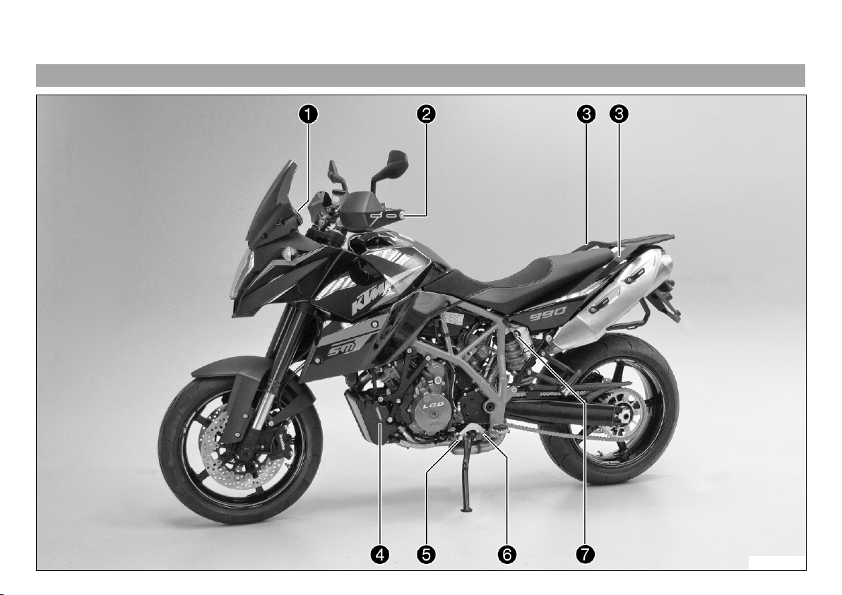
4.1 View of vehicle, front left side (example)
L00600-10
Page 19

4 VIEW OF VEHICLE 17
1 Function buttons ( p. 29)
1 indicator lamps ( p. 30)
2 Clutch lever ( p. 23)
3 Handrails ( p. 42)
4 Level viewer, engine oil
5 Shift lever ( p. 44)
6 Engine number ( p. 21)
7 Compression damping of the shock absorber ( p. 69)
Page 20
4 VIEW OF VEHICLE 18
4.2 View of vehicle, rear right side (example)
L00601-10
Page 21

4 VIEW OF VEHICLE 19
1 Seat lock ( p. 41)
2 Light switch ( p. 25)
2 Headlight flasher switch ( p. 25)
2 Turn signal switch ( p. 26)
2 Horn button ( p. 24)
3 Filler cap
4 Emergency OFF switch ( p. 26)
4 Electric starter button ( p. 27)
5 Hand brake lever ( p. 23)
6 Fork rebound setting and spring preload setting
7 Passenger footrests ( p. 43)
8 Shock absorber setting, spring preload adjuster
9 Foot brake lever ( p. 45)
10 Chassis number/type label
11 Fork compression adjustment
Page 22
5 SERIAL NUMBERS 20
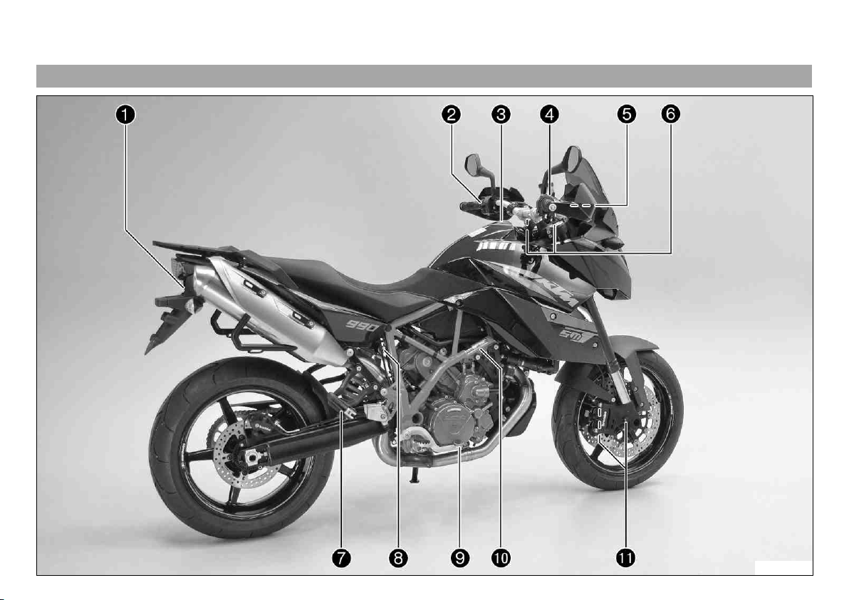
5.1 Chassis number
Chassis number 1 is embossed in the steering head at the right.
L00604-10
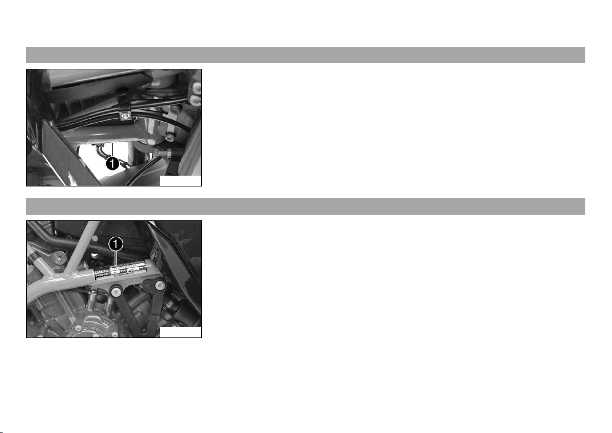
5.2 Type label
Type label 1 is located on the upper frame tube on the right.
L00603-10
Page 23
5 SERIAL NUMBERS 21
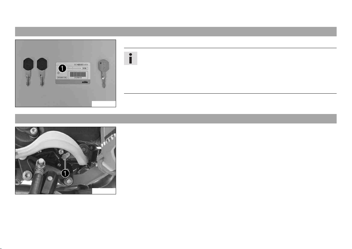
5.3 Key number
The Code number 1 key number can be found on the KEYCODECARD.
Info
You need the key number to order a spare key. Keep the KEYCODECARD in a safe
place.
Use the orange programming key to activate and deactivate the black ignition key.
Keep the orange programming key in a safe place: it must only be used for learning
and programming functions.
700563-01
5.4 Engine number
The engine number 1 is stamped on the left side of the engine under the engine sprocket.
L00602-10
Page 24
5 SERIAL NUMBERS 22
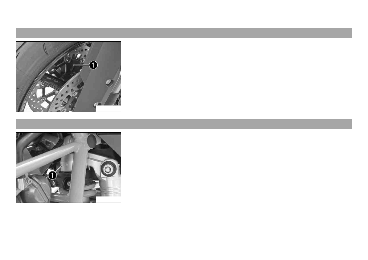
5.5 Fork part number
The fork part number 1 is stamped on the inner side of the fork stub.
B00606-10
5.6 Shock absorber part number
The shock absorber part number 1 is stamped on the top of the shock absorber above the
adjusting ring on the engine side.
L00606-10
Page 25
6 CONTROLS 23
6.1 Clutch lever
The clutch lever 1 is fitted on the left side of the handlebar.
The clutch is hydraulically operated and self-adjusting.
B00608-10
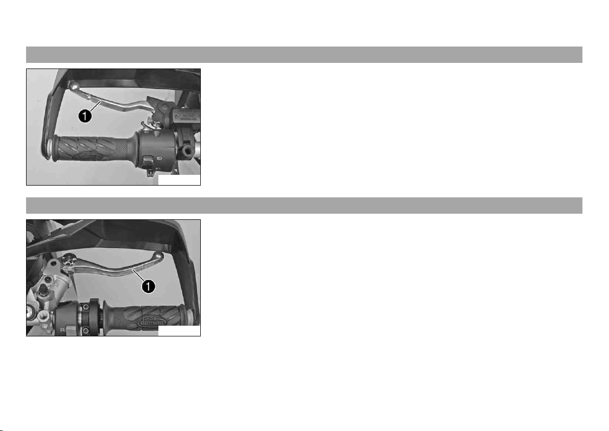
6.2 Hand brake lever
The hand brake lever 1 is fitted on the right side of the handlebar.
The front brake is engaged using the hand brake lever.
B00609-10
Page 26
6 CONTROLS 24
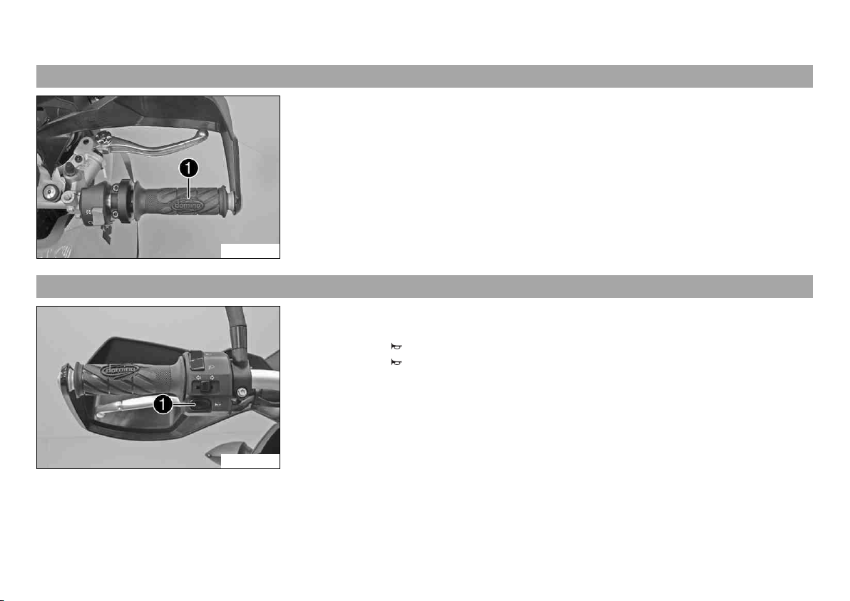
6.3 Throttle grip
The throttle grip 1 is fitted on the right side of the handlebar.
B00655-10
6.4 Horn button
The horn button 1 is fitted on the left side of the handlebar.
Possible states
• Horn button in basic position
• Horn button pressed – The horn is operated in this position.
B00656-12
Page 27
6 CONTROLS 25
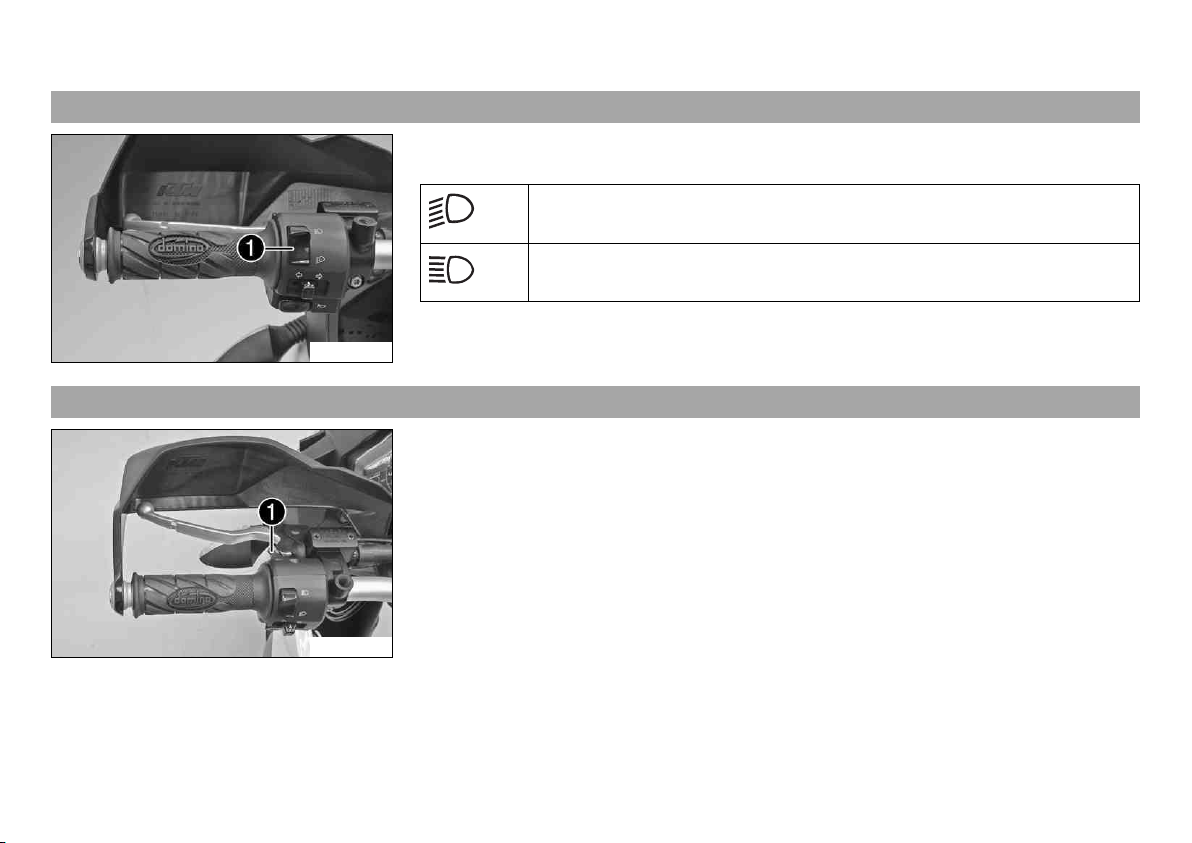
6.5 Light switch
The light switch 1 is fitted on the left side of the handlebar.
Possible states
Low beam on – The light switch is turned downward. In this position, the
low beam and tail light are switched on.
High beam on – The light switch is turned upwards. In this position, the
high beam and tail light are switched on.
B00684-10
6.6 Headlight flasher switch
The headlight flasher switch 1 is fitted on the left side of the handlebar.
Possible states
• Headlight flasher switch in basic position
• Headlight flasher switch pressed – The headlight flasher switch (high beam) is operated in this position.
B00685-10
Page 28
6 CONTROLS 26
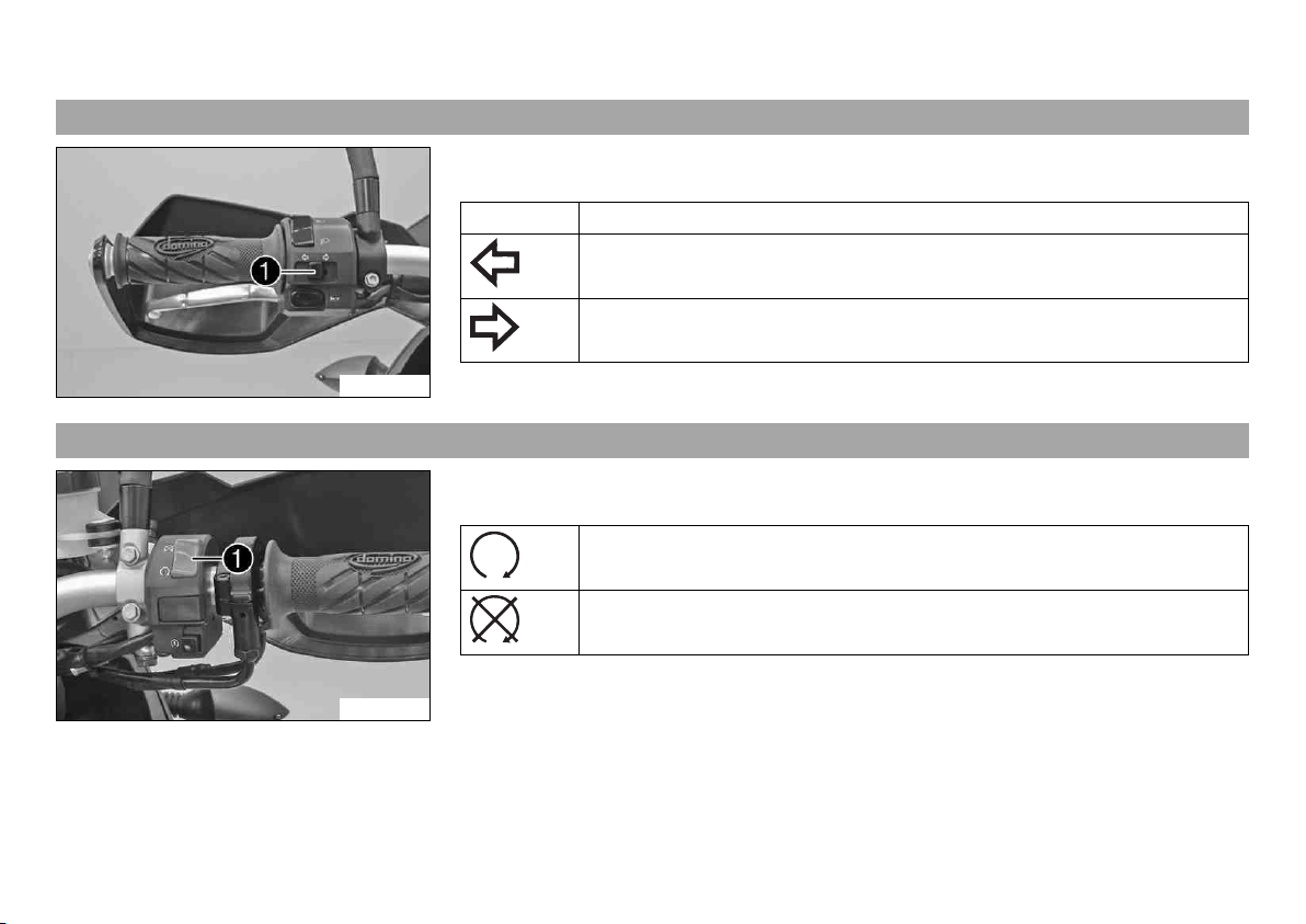
6.7 Turn signal switch
The turn signal switch 1 is fitted on the left side of the handlebar.
Possible states
Turn signal off
Left turn signal on – The turn signal switch is pressed to the left. The turn
signal switch automatically returns to the central position after use.
Right turn signal on – The turn signal switch is pressed to the right. The
turn signal switch automatically returns to the central position after use.
B00656-11
6.8 Emergency OFF switch
B00657-10
To switch off the turn signal, press the turn signal switch towards the switch case.
The emergency OFF switch 1 is fitted on the right side of the handlebar.
Possible states
Emergency OFF switch on – This position is necessary for operation as it
closes the ignition circuit.
Emergency OFF switch off – In this position, the ignition circuit is interrupted, a running engine stops, and the engine cannot be started.
Page 29
6 CONTROLS 27
6.9 Electric starter button
The electric starter button 1 is fitted on the right side of the handlebar.
Possible states
• Electric starter button in basic position
• Electric starter button pressed – The electric starter is actuated in this position.
B00657-11
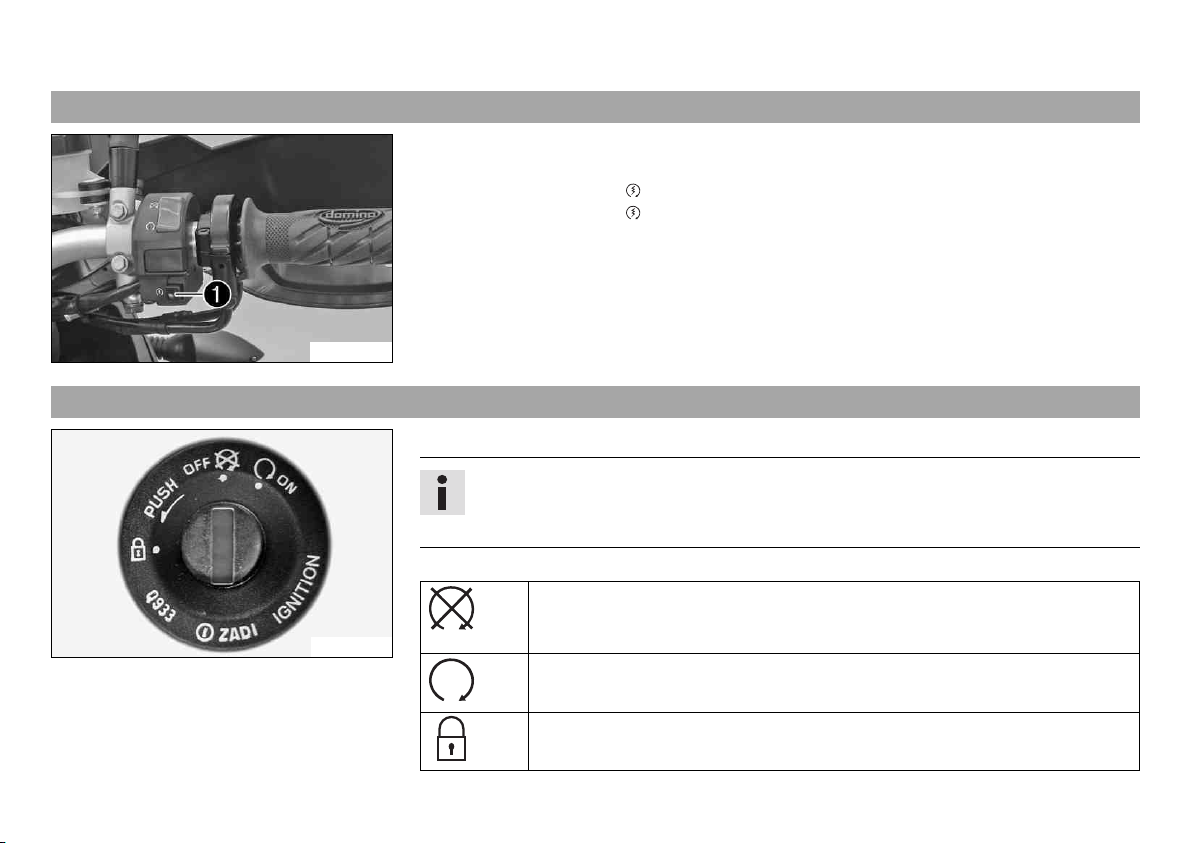
6.10 Ignition/steering lock
The ignition/steering lock is in front of the upper triple clamp.
Info
The ignition may only be switched on using a black ignition key.
Use the orange programming key to activate and deactivate the black ignition key.
Possible states
Ignition OFF – In this position, the ignition circuit is interrupted, a running
engine stops, and a non-running engine will not start. The ignition key can
600825-01
be removed.
Ignition ON – In this position, the ignition circuit is closed and the engine
can be started.
Steering locked – In this position, the ignition circuit is interrupted and the
steering locked. The ignition key can be removed.
Page 30
6 CONTROLS 28
6.11 Immobilizer
The electronic immobilizer secures the vehicle against unauthorized use.
The immobilizer is activated automatically and the engine electronics are locked when the
ignition key is withdrawn.
The red warning lamp flashes at 15 second intervals after one minute.
The red warning lamp can also indicate errors by flashing.
Info
The ignition key contains electronic components. Never attach multiple ignition keys
to a single key ring; this may cause mutual interference and lead to problems.
400887-01
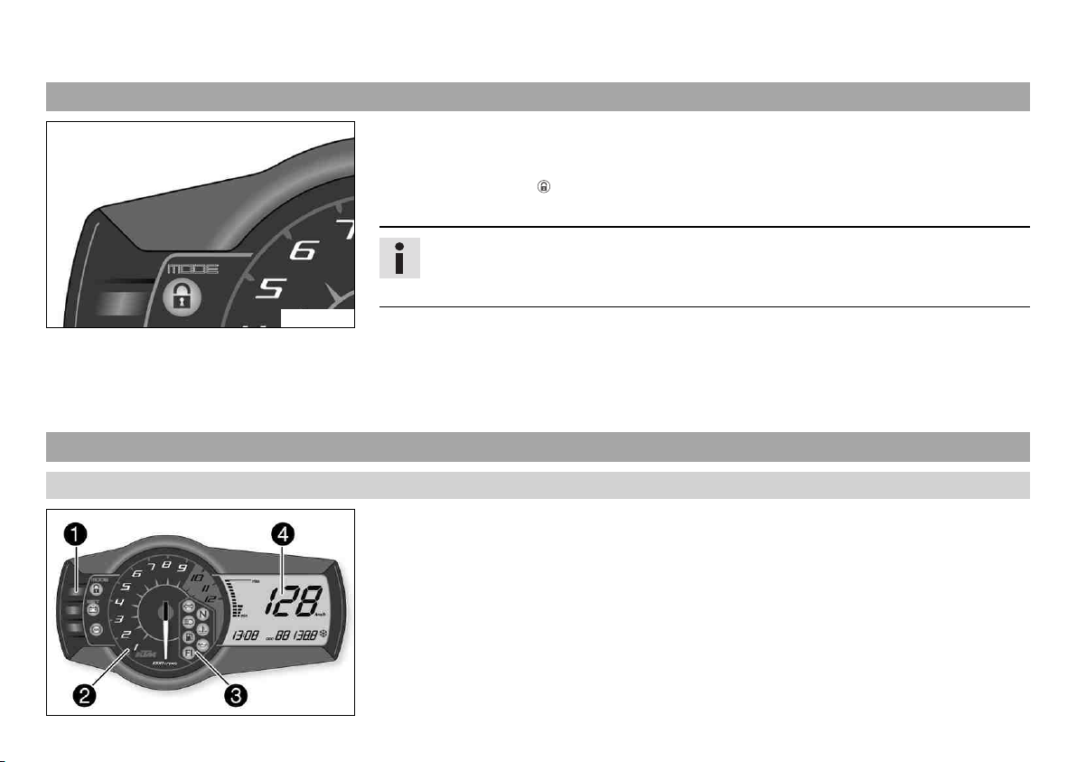
6.12 Combination instrument
6.12.1 Overview
A lost black ignition key must be deactivated to prevent unauthorized persons from operating the vehicle.
The second black ignition key is activated when the vehicle is shipped.
Another two spare ignition keys (key number on the KEYCODECARD) can be ordered from an
authorized KTM workshop, but they need to be activated for use.
The combination instrument is installed in front of the handlebar.
The combination instrument is divided into 4 function areas.
1 Function buttons
2 Tachometer
3 Indicator lights
4 Display
400885-10
Page 31

6 CONTROLS 29
6.12.2 Function buttons
You can change the display mode with the MODE button 1.
Possible display modes are the distance traveled (ODO), trip master 1 (TRIP 1), trip master 2 (TRIP 2), and the ambient temperature.
Press the SET button 2 to reset the trip master 1 function (TRIP 1) and trip master 2 function (TRIP 2) to 0.0.
The ABS can be switched off using button 3.
400886-10
6.12.3 Tachometer
The tachometer 1 shows the engine speed in revolutions per minute.
The red marking 2 shows the excess speed range of the engine.
400888-10
Page 32

6 CONTROLS 30
6.12.4 indicator lamps
The indicator lamps offer additional information about the operating state of the motorcycle.
Possible states
The turn signal indicator light flashes green simultaneously with the turn
signal – The turn signal is switched on.
The idling speed indicator lamp lights up green – The transmission is
shifted to idle.
400889-01
The high beam indicator light lights up blue – The high beam is switched
on.
The temperature warning lamp lights up red – The coolant temperature has
reached a critical value.
The low fuel warning lamp lights up yellow – The fuel level has reached the
reserve mark. The display switches to TRIP F.
The oil pressure warning lamp lights up red – The oil pressure is too low.
FI warning lamp (MIL) lights up/flashes yellow – The OBD (on-board diagno-
sis) has detected an emission- or safety-critical error.
The immobilizer indicator lamp lights up or flashes red – Status or error
message for immobilizer/alarm system.
The battery warning lamp lights up red – The voltage in the vehicle system
is too low.
ABS warning lamp lights up/flashes yellow – Status or error messages relating to ABS (antilock brake system).
Page 33

6 CONTROLS 31
6.12.5 Display
When you switch on the ignition, all display segments light up for one second as a function
check.
400892-01
LEnGth
Following the display function check, the LEnGth wheel circumference is shown for one second.
Info
1870 mm corresponds to the circumference of the 17" front wheel with a series production tire.
The display then changes to the last selected mode.
400881-01
Page 34

6 CONTROLS 32
6.12.6 Speed display
The speed 1 is shown in kilometers per hour km/h or in miles per hour mph.
400838-10
6.12.7 Setting kilometers or miles
Info
If you change the unit, the value ODO is retained and converted accordingly.
Making the setting according to the country.
Condition
The motorcycle is stationary.
Page 35

6 CONTROLS 33
– Switch on the ignition by turning the ignition key to the ON position.
– Press the MODE button repeatedly until the ODO mode is active.
– Keep the MODE button pressed until the display mode changes from km/h to mph or
from mph to km/h.
400893-10
6.12.8 Time
The time is shown in area 1 of the display.
Info
After reconnecting the battery or changing the fuse, the time must be reset.
400893-11
6.12.9 Setting the clock
Condition
The motorcycle is stationary.
Page 36

6 CONTROLS 34
– Switch on the ignition by turning the ignition key to the ON position.
– Press the MODE button repeatedly until the ODO mode is active.
– Keep the MODE button and the SET button pressed simultaneously.
The time display begins to flash.
– Press the MODE button to set the hour.
– Press the SET button to set the minute.
– Keep the MODE button and the SET button pressed simultaneously.
400893-12
6.12.10 ODO display
In the ODO display mode, the total distance traveled is shown in kilometers or miles.
400839-01
The time is set.
Info
This value is retained, even if the battery is disconnected and/or the fuse blows.
6.12.11 Setting/resetting display TRIP 1
Info
The TRIP 1 trip counter is always running and counts up to 999.9.
The trip counter can be used to measure the distance covered during trips or between two refueling stops. After the value 999.9 is
reached, the trip counter starts at 0.0 again.
Page 37

6 CONTROLS 35
– Switch on the ignition by turning the ignition key to the ON position.
– Press the MODE button repeatedly until the TRIP 1 mode is active.
– Keep the SET button pressed.
The TRIP 1 display is set to 0.0.
400840-01
6.12.12 Setting/resetting display TRIP 2
Info
The TRIP 2 trip counter is always running and counts up to 999.9.
The trip counter can be used to measure the distance covered during trips or between two refueling stops. After the value 999.9 is
reached, the trip counter starts at 0.0 again.
– Switch on the ignition by turning the ignition key to the ON position.
– Press the MODE button repeatedly until the TRIP 2 mode is active.
– Keep the SET button pressed.
The TRIP 2 display is set to 0.0.
400841-01
Page 38

6 CONTROLS 36
6.12.13 TRIP F display
If the fuel level drops to the reserve mark, the display automatically changes to TRIP F and
starts to count from 0.0, regardless of the previous display mode.
Info
The low fuel warning lamp lights up in parallel to the TRIP F display.
400842-01
6.12.14 Ambient temperature indicator
The ambient temperature 1 is displayed in °C or °F.
400893-13
6.12.15 Setting the temperature units
Condition
The motorcycle is stationary.
Page 39

6 CONTROLS 37
– Switch on the ignition by turning the ignition key to the ON position.
– Press the MODE button repeatedly until the ambient temperature is active.
– Keep the MODE button pressed until the display mode changes from °C to °F or from °F
to °C.
400893-14
6.12.16 Warning of icy roads
The ice symbol lights up to indicate an increased danger of slippery roads.
The ice symbol appears in the display when the ambient temperature drops below the
specified value.
Temperature 3 °C (37 °F)
The ice symbol goes out in the display when the ambient temperature rises above the
specified value again.
Temperature 4 °C (39 °F)
400894-10
Page 40

6 CONTROLS 38
6.12.17 Coolant temperature indicator
The temperature display consists of 12 bars. The more bars that light up, the hotter the
coolant. When the upper bar lights up, all bars in the display begin to flash and the temperature warning lamp lights up.
Possible states
• Engine cold – Up to five bars light up.
• The engine is warm – Six to eleven bars light up.
• Engine hot – All twelve bars flash.
700124-01
6.13 Hazard warning flasher switch/hazard warning flasher
The hazard warning flasher switch 1 is fitted next to the combination instrument on the
left.
The hazard warning flasher is used to indicate emergency situations.
Info
The hazard warning flasher can be activated or deactivated while the ignition is
switched on or up to 30 seconds after the ignition is switched off.
Do not keep the hazard warning flashers activated longer than necessary as they
deplete the batteries.
B00658-10
Possible states
Hazard warning flasher off
Hazard warning flasher on – All four turn signals, the hazard warning
flasher switch, and the green turn signal indicator light in the combination
instrument flash.
Page 41

6 CONTROLS 39
6.14 Socket for electrical accessories
Socket 1 for electrical accessories is fitted next to the ignition/steering wheel lock on the
left.
It is connected to the battery without an additional switch.
Socket for electrical accessories
Voltage 12 V
Maximum current con-
sumption
B00614-10
6.15 Opening the filler cap
Danger
Fire hazard Fuel is highly flammable.
– Never refuel the vehicle near open flames or burning cigarettes, and always switch off the engine first. Be careful that no fuel is
spilt, especially on hot vehicle components. Clean up spilt fuel immediately.
– Fuel in the fuel tank expands when warm and can escape if the tank is overfilled. See the notes on refueling.
Warning
Danger of poisoning Fuel is poisonous and a health hazard.
– Avoid contact between fuel and skin, eyes and clothing. Do not inhale fuel vapors. If fuel gets into your eyes, rinse immediately
with water and contact a doctor. Wash affected skin areas immediately with soap and water. If fuel is swallowed, contact a doctor immediately. Change clothing that has come into contact with fuel. Store fuel in a suitable canister according to regulations
and keep it out of the reach of children.
10 A
Page 42

6 CONTROLS 40
Warning
Environmental hazard Improper handling of fuel is a danger to the environment.
– Do not allow fuel to get into the ground water, the ground, or the sewage system.
– Lift the cover of the filler cap 1 and insert the ignition key.
Note
Danger of damage Ignition key breakage.
– To take pressure off of the ignition key, push down on the filler cap. Damaged igni-
tion keys must be replaced.
– Turn the ignition key 90° counterclockwise and remove the filler cap.
L00607-10
6.16 Closing the filler cap
L00608-01
Info
The filler cap has a tank air vent system.
– Put the filler cap back on and turn the ignition key 90° clockwise.
– Remove the ignition key and fold down the cover.
Page 43

6 CONTROLS 41
6.17 Seat lock
Seat lock 1 is located at the rear under the tail light.
It can be locked with the ignition key.
600922-10
6.18 Tool set
The tool set 1 is located in the storage compartment under the seat.
B00612-10
Page 44

6 CONTROLS 42
6.19 Handrails
The handrails 1 are used for moving the motorcycle around.
If you carry a passenger, the passenger can hold onto the handrails during the trip.
600923-10
6.20 Helmet lock
Warning
Danger of accidents Impairment of ride behavior and vehicle operation if a helmet
or helmet lock is attached to the vehicle.
– Do not use the helmet lock for holding a helmet or other objects during the jour-
ney. Always remove the helmet lock before starting out.
The steel cable 1 in the tool set can be used to lock a helmet to the vehicle to prevent it
from being stolen.
L00609-10
Page 45

6 CONTROLS 43
6.21 Luggage rack plate
The luggage rack plate 1 is located behind the seat.
The base plate of a luggage system can be mounted on the luggage rack plate (optional).
The luggage rack plate may not be loaded with more than the specified weight.
6.22 Passenger footrests
L00605-10
L00611-01
Maximum permissible load of
luggage rack plate
8 kg (18 lb.)
Info
Follow the instructions provided by the luggage manufacturer.
The passenger footrests can be folded up and down.
Possible states
• Passenger footrests folded up – For operation without a passenger.
• Passenger footrests folded down – For operation with a passenger.
Page 46

6 CONTROLS 44
6.23 Shift lever
Shift lever 1 is mounted on the left side of the engine.
L00610-11
The gear positions can be seen in the photograph.
The neutral or idle position N is between the first and second gear.
L00610-10
Page 47

6 CONTROLS 45
6.24 Foot brake lever
Foot brake lever 1 is located in front of the right footrest.
The rear brake is activated using the foot brake lever.
L00613-10
6.25 Side stand
The side stand 1 is located on the left side of the vehicle.
The side stand is used to park the motorcycle.
Info
The side stand must be folded up during motorcycle use.
The side stand is coupled with the safety starting system – see the riding instructions.
Possible states
L00612-10
• Side stand folded out – The vehicle can be supported on the side stand. The safety
starting system is active.
• Side stand folded in – This position is mandatory when riding the motorcycle. The
safety starting system is inactive.
Page 48

7 PREPARING FOR USE 46
7.1 Information on first use
Danger
Danger of accidents Danger arising from the rider's judgement being impaired.
– Do not operate the vehicle while under the influence of alcohol, drugs and certain medications or physically or mentally
impaired.
Warning
Risk of injury Missing or poor protective clothing presents an increased safety risk.
– Wear protective clothing (helmet, boots, gloves, pants and jacket with protectors) every time you ride the vehicle. Always wear
protective clothing that is in good condition and meets the legal requirements.
Warning
Danger of crashing Poor vehicle handling due to different tire tread patterns on front and rear wheels.
– The front and rear wheels must be fitted with tires with similar tread patterns to prevent loss of control over the vehicle.
Warning
Danger of accidents Uncontrollable handling characteristic due to non-approved and/or non-recommended tires/wheels.
– Only tires/wheels approved by KTM and with the corresponding speed index should be used.
Warning
Danger of accidents Reduced road grip with new tires.
– New tires have a smooth rolling surface and therefore cannot provide full road grip. The entire rolling surface must be rough-
ened in the first 200 kilometers (124.3 miles) by moderate riding at alternating angles. The full grip levels are not achieved
until the tires have been run in.
Info
When using your vehicle, remember that others may feel disturbed by excessive noise.
Page 49

7 PREPARING FOR USE 47
– Make sure that the pre-delivery inspection work has been carried out by an authorized KTM workshop.
You receive a delivery certificate and the service record at vehicle handover.
– Before your first trip, read the entire operating instructions carefully.
– Familiarize yourself with the controls.
– Adjust the basic position of the clutch lever. ( p. 92)
– Adjust the basic position of hand brake lever. ( p. 95)
– Adjust the basic position of foot brake lever. ( p. 100)
– Get used to handling the vehicle on empty suitable terrain before making a longer trip. Try also to ride as slowly as possible to get a
better feeling for the motorcycle.
– Hold the handlebar firmly with both hands and keep your feet on the footrests when riding.
– Run the engine in. ( p. 47)
7.2 Running in the engine
– Do not exceed the specified engine speed and load during the running-in period.
Guideline
Maximum engine speed
During the first: 1,000 km (621.4 mi) 6,500 rpm
After the first: 1,000 km (621.4 mi) 9,600 rpm
– Avoid full-throttle operation!
7.3 Loading the vehicle
Warning
Danger of accidents Unstable handling characteristics.
– Do not exceed the maximum permitted weight and axle loads. The overall weight consists of: motorcycle operational and with a
full tank, driver and passenger with protective clothing and helmet, baggage.
Page 50

7 PREPARING FOR USE 48
Warning
Danger of accidents Unstable handling characteristics due to incorrect mounting of suitcase and/or tank rucksack.
– Mount and secure suitcase and tank rucksack according to the manufacturer's instructions.
Warning
Danger of accidents Unstable handling characteristics at high speed.
– Adapt your speed according to your payload. If the motorcycle is loaded with luggage, ride more slowly.
Maximum speed with luggage 130 km/h (80.8 mph)
Warning
Danger of accidents Destruction of luggage carrier system.
– If the motorcycle is fitted with luggage cases, note the manufacturer's specifications concerning the maximum payload.
Warning
Danger of accidents Poor visibility for other road users due to slipped baggage.
– If the tail light is covered, you are less visible to traffic behind you, especially in the dark. Check that your baggage is fixed
properly at regular intervals.
Warning
Danger of accidents Changed handling characteristics and longer stopping distance with excessive payload.
– Adapt your speed according to your payload.
Warning
Danger of accidents Unstable handling characteristics due to slipped baggage.
– Check the way your baggage is fixed regularly.
Warning
Danger of burns A hot exhaust system can burn baggage.
– Fasten your baggage in such a way that it cannot be burned or singed by the hot exhaust system.
Page 51

7 PREPARING FOR USE 49
– If you are carrying baggage, make sure it is fixed firmly as close as possible to the center of the vehicle and ensure even weight distri-
bution between the front and rear wheels.
– Do not exceed the maximum permissible total weight and the axle loads.
Guideline
Maximum permissible total weight 400 kg (882 lb.)
Maximum permissible front axle load 160 kg (353 lb.)
Maximum permissible rear axle load 250 kg (551 lb.)
Page 52

8 RIDING INSTRUCTIONS 50
8.1 Checks and maintenance measures when preparing for use
Info
Before every trip, check the condition of the vehicle and ensure that it is roadworthy.
The vehicle must be in perfect technical condition when it is being operated.
– Check the engine oil level. ( p. 162)
– Check the front brake fluid level. ( p. 96)
– Check the rear brake fluid level. ( p. 101)
– Check the front brake linings. ( p. 98)
– Check the rear brake linings. ( p. 104)
– Check that the brake system is functioning properly.
– Check the coolant level in the compensating tank. ( p. 152)
– Check the chain for dirt. ( p. 84)
– Check the chain tension. ( p. 86)
– Check the tire condition. ( p. 114)
– Check the tire air pressure. ( p. 115)
– Check that all controls are correctly adjusted and free to move.
– Check that the electrical equipment is functioning properly.
– Check that baggage is correctly secured.
– Sit on the motorcycle and check the rear mirror setting.
– Check the fuel level.
Page 53

8 RIDING INSTRUCTIONS 51
8.2 Starting
Danger
Danger of poisoning Exhaust gases are toxic and inhaling them may result in unconsciousness and/or death.
– When running the engine, always make sure there is sufficient ventilation, and do not start or run the engine in an enclosed
space without an effective exhaust extraction system.
Caution
Danger of accidents If the vehicle is operated with a discharged battery or without a battery, electronic components and safety
equipment may be damaged.
– Never operate the vehicle with a discharged battery or without a battery.
Note
Engine failure High engine speeds in cold engines have a negative effect on the service life of the engine.
– Always warm up the engine at low engine speeds.
– Press the emergency OFF switch into the position .
– Switch on the ignition by turning the ignition key to the ON position.
After you switch on the ignition, you can hear the fuel pump working for about two
seconds. The function check of the combination instrument is run at the same
time.
The ABS warning lamp lights up and goes back out after starting off.
– Shift the transmission to neutral.
The green idling speed indicator lamp N 1 lights up.
B00650-10
– Press the electric starter button .
Page 54

8 RIDING INSTRUCTIONS 52
Info
Do not press the electric starter button until the combination instrument function check is finished.
When starting, DO NOT open the throttle. If you open the throttle during the starting procedure, fuel is not injected by the engine management system and the
engine cannot start.
Press the starter for a maximum of 5 seconds. Wait for a least 5 seconds before
trying again.
This motorcycle is equipped with a safety starting system. You can only start the
engine if the transmission is in neutral or if the clutch is pulled when a gear is
engaged. If the side stand is folded out and you shift into gear and release the
clutch, the engine stops.
– Take the weight off the side stand and swing it upwards with your foot as far as it will
go.
Switching off ABS
KTM recommends riding with ABS at all times. However, situations may arise in which
ABS is not advantageous.
Condition
Vehicle stationary, engine running.
– Press button 2 for 3 - 5 seconds.
The ABS warning lamp starts flashing; ABS is deactivated.
400886-11
Page 55

8 RIDING INSTRUCTIONS 53
8.3 Starting off
– Pull the clutch lever, engage 1st gear, release the clutch lever slowly and simultaneously open the throttle carefully.
8.4 Shifting, riding
Warning
Danger of accidents Abrupt load alterations can cause the vehicle to get out of control.
– Avoid abrupt load alterations and sudden braking actions, and adapt your speed to the road conditions.
Warning
Danger of accidents If you change down at high engine speed, the rear wheel can lock up.
– Do not change into a low gear at high engine speed. The engine races and the rear wheel can lock up.
Warning
Danger of accidents Malfunctions caused by incorrect ignition key position.
– Do not change the ignition key position during a journey.
Warning
Danger of accidents Distraction from traffic activity by adjustments to the vehicle.
– Make all adjustments when the vehicle is at a standstill.
Warning
Risk of injury The passenger must be able to hold himself or herself properly on the passenger seat.
– The passenger must hold on to the rider or supporting strap firmly and place his/her feet on the passenger footrests. Observe
the regulations concerning the minimum age for passengers in your country.
Warning
Danger of accidents Danger of accidents caused by dangerous driving.
– Comply with traffic regulations and ride defensively and foresightedly to detect sources of danger early on.
Page 56

8 RIDING INSTRUCTIONS 54
Warning
Danger of accidents Reduced road grip with cold tires.
– On every journey, take the first miles carefully at moderate speed until the tires reach operating temperature and optimal road
grip is ensured.
Warning
Danger of accidents Reduced road grip with new tires.
– New tires have a smooth rolling surface and therefore cannot provide full road grip. The entire rolling surface must be rough-
ened in the first 200 kilometers (124.3 miles) by moderate riding at alternating angles. The full grip levels are not achieved
until the tires have been run in.
Warning
Danger of accidents Unstable handling characteristics.
– Do not exceed the maximum permitted weight and axle loads. The overall weight consists of: motorcycle operational and with a
full tank, driver and passenger with protective clothing and helmet, baggage.
Warning
Danger of accidents Unstable handling characteristics due to slipped baggage.
– Check the way your baggage is fixed regularly.
Warning
Danger of accidents Lack of roadworthiness.
– After a fall, check the vehicle as usual before preparing for use.
Note
Engine failure Unfiltered intake air has a negative effect on the service life of the engine.
– Never ride the vehicle without an air filter since dust and dirt can get into the engine and result in increased wear.
Page 57

8 RIDING INSTRUCTIONS 55
Note
Engine damage Engine overheating.
– If the coolant temperature warning lamp lights up, stop the vehicle and switch off the engine. Let the engine cool, check the coolant
level in the radiator, and correct it if necessary. If you continue riding while the coolant temperature warning lamp is lit, the engine
may be damaged.
Info
If you hear unusual noises while riding, stop immediately, switch off the engine and contact an authorized KTM workshop.
– When conditions allow (incline, road situation, etc.), you can shift into a higher gear.
– Release the throttle while simultaneously pulling the clutch lever, shift into the next
gear, release the clutch and open the throttle.
Info
You can see the positions of the six forward gears in the figure. The neutral or
idle position is between the first and second gears. First gear is used for starting
off or for steep inclines.
L00610-10
– After reaching maximum speed by fully opening the throttle grip, turn the throttle back
so it is ¾ open. This will barely reduce the speed but fuel consumption will be considerably lower.
– Accelerate only up to a speed suitable for the road surface and weather conditions.
When traveling in bends, do not shift, and accelerate very carefully.
– To shift down, brake if necessary and close the throttle at the same time.
– Pull the clutch lever and shift into a lower gear, release the clutch lever slowly and open
the throttle or shift again.
– If the engine stalls (e.g. at a crossroads), pull the clutch lever only and press the elec-
tric starter button. You do not have to shift into neutral.
Page 58

8 RIDING INSTRUCTIONS 56
– Switch off the engine if you expect to be standing for a long time.
– If the FI warning lamp (MIL) lights up during a trip, stop immediately. When you shift to
neutral, the FI warning lamp (MIL) starts to flash.
Info
From the flashing rhythm, you can derive a two-digit number, the so-called
flashing code. The flashing code tells you which component has a fault.
– If the ice symbol appears on the combination instrument, roads may be icy. Adjust
your speed to the road conditions.
8.5 Braking
Warning
Danger of accidents Reduced braking efficiency due to a wet or dirty brake system.
– Clean or dry a dirty or wet brake system by riding and braking gently.
Warning
Danger of accidents Reduced braking efficiency caused by spongy pressure point of front or rear brake.
– Check the brake system and do not continue riding. (Your authorized KTM workshop will be glad to help.)
Warning
Danger of accidents Failure of brake system.
– If the foot brake lever is not released, the brake linings drag continuously. The rear brake may fail due to overheating. Take your
foot off the foot brake lever when you are not braking.
Warning
Danger of accidents Longer stopping distance due to higher overall weight.
– Take the longer stopping distance into account when carrying a passenger and baggage.
Page 59

8 RIDING INSTRUCTIONS 57
Warning
Danger of accidents Delayed brake action on salted roads.
– There may be salt deposits on the brake discs. In order to restore the normal braking efficiency, you will need to remove the
deposits from the discs by carefully applying the brakes.
Warning
Danger of accidents Greater stopping distance due to ABS.
– Braking should be appropriate to the driving situation and the road conditions.
Warning
Danger of accidents Excessively forceful braking can cause the wheels to block.
– ABS must be switched on to be effective.
Warning
Danger of accidents Locking of the wheels due to braking action of the engine.
– Pull the clutch during emergency braking, full brake application and when braking on a slippery surface.
– When braking, first throttle back and then apply the front and rear brakes at the same time.
Info
When ABS is active, you can achieve maximum braking power even on low grip surfaces such as sandy, wet, or slippery terrain
without locking of the tires.
Warning
Danger of accidents Road grip is reduced when braking with the motorcycle at an angle or on a laterally inclined surface.
– Braking should be completed before you enter into a bend.
– Braking should always be completed before you enter a bend. Shift down to a lower gear that is appropriate to your speed.
Page 60

8 RIDING INSTRUCTIONS 58
– On long downhill stretches, use the braking effect of the engine. Do this by changing down two gears, but do not race the engine. You
will require less braking force and the brakes will not overheat.
8.6 Stopping, parking
Warning
Risk of misappropriation Usage by unauthorized persons.
– Never leave the vehicle while the engine is running. Secure the vehicle against use by unauthorized persons. If you leave the
vehicle, lock the steering and remove the ignition key.
Warning
Danger of burns Some vehicle components become very hot when the vehicle is operated.
– Do not touch hot components such as exhaust system, radiator, engine, shock absorber, and the brake system. Allow these
components to cool down before starting work on them.
Note
Danger of damage The parked vehicle may roll away or fall over.
– Always place the vehicle on a firm and even surface.
Note
Fire hazard Some vehicle components become very hot when the vehicle is operated.
– Do not park the vehicle near flammable or explosive substances. Do not place objects on the vehicle while it is still warm from being
run. Always let the vehicle cool first.
Note
Material damage Damage and destruction of components by excessive load.
– The side stand is designed for the weight of the motorcycle only. Do not sit on the motorcycle when it is supported by the side stand
only. The side stand and/or the frame could be damaged and the motorcycle could fall over.
Page 61

8 RIDING INSTRUCTIONS 59
– Apply the brakes.
– Shift the transmission to neutral.
– Switch off the ignition by turning the ignition key to the OFF position.
Info
If you switch off the engine with the emergency OFF switch but the ignition remains switched on at the ignition lock, power
continues to flow to most power consumers and the battery is soon discharged. Therefore, always switch off the engine with the
ignition key; the emergency OFF switch is provided for emergency situations only.
– Park the motorcycle on a firm surface.
– Swing the side stand to the front with your foot as far as it will go, and lean the vehicle onto it.
– Lock the steering by turning the handlebar fully to the left, pressing down the ignition key to the OFF position and turning it to
the position . To make the steering lock engage more easily, move the handlebar back and forth slightly. Remove the ignition key.
8.7 Transport
Note
Danger of damage The parked vehicle may roll away or fall over.
– Always place the vehicle on a firm and even surface.
Note
Fire hazard Some vehicle components become very hot when the vehicle is operated.
– Do not park the vehicle near flammable or explosive substances. Do not place objects on the vehicle while it is still warm from being
run. Always let the vehicle cool first.
Page 62

8 RIDING INSTRUCTIONS 60
– Switch off the engine and remove the ignition key.
– Use tension belts or other suitable devices to secure the motorcycle against accidents
or falling over.
401448-01
8.8 Refueling
Danger
Fire hazard Fuel is highly flammable.
– Never refuel the vehicle near open flames or burning cigarettes, and always switch off the engine first. Be careful that no fuel is
spilt, especially on hot vehicle components. Clean up spilt fuel immediately.
– Fuel in the fuel tank expands when warm and can escape if the tank is overfilled. See the notes on refueling.
Warning
Danger of poisoning Fuel is poisonous and a health hazard.
– Avoid contact of the fuel with skin, eyes and clothing. Do not inhale fuel vapors. If fuel gets into your eyes, rinse immediately
with water and contact a doctor. Wash affected skin areas immediately with soap and water. If fuel is swallowed, contact a doctor immediately. Change clothing that has come into contact with fuel.
Note
Material damage Premature clogging of the fuel filter.
– In some countries and regions, the available fuel quality and cleanliness may not be sufficient. This will result in problems with the
fuel system. (Your authorized KTM workshop will be glad to help.)
Page 63

8 RIDING INSTRUCTIONS 61
– Only refuel with clean fuel that meets the specified standards.
Warning
Environmental hazard Improper handling of fuel is a danger to the environment.
– Do not allow fuel to get into the ground water, the ground, or the sewage system.
– Switch off the engine.
– Open the filler cap. ( p. 39)
– Fill the fuel tank with fuel no higher than level A.
Guideline
Distance A 35 mm (1.38 in)
401182-10
400885-12
Total fuel tank
capacity, approx.
– Close the filler cap. ( p. 40)
– Press the SET button 2 for two seconds.
The low fuel warning lamp 1 goes out. TRIP F is set to 0.0 and the display returns
to the previous display mode.
19 l (5 US gal) Super unleaded (ROZ 95/RON 95/PON
Info
If you do not press the SET button 2, the reset takes place automatically after
approx. three minutes.
91) ( p. 204)
Page 64

9 SERVICE SCHEDULE 62
9.1 Service schedule
K10N K75A K150A K300A
Check that the electrical equipment is functioning properly. • • • •
Read out the trouble code memory using the KTM diagnostics tool. x
Check the measured service values with the KTM diagnostics tool. x
Change the engine oil and filter, clean the oil screens. x ( p. 163)
Check the oil jet for the clutch lubrication. x
Check the front brake linings. ( p. 98) • • • •
Check the front brake discs. ( p. 95) • • • •
Check the rear brake linings. ( p. 104) • • • •
Check the rear brake disc. ( p. 101) • • • •
Check that brake lines are undamaged and free of leaks. • • • •
Check the rear brake fluid level. ( p. 101) • • • •
Check the free travel of the foot brake lever. ( p. 99) • • • •
Check the shock absorber and fork for leaks. Perform a fork and shock absorber service if needed
and depending on vehicle use.
Check the swingarm bearings. x
Check the wheel bearing for play. x
Check the tire condition. ( p. 114) • • • •
Check the tire air pressure. ( p. 115) • • • •
Check the chain, rear sprocket, engine sprocket, and chain guide. ( p. 89) • • •
Check the chain tension. ( p. 86) • • • •
Lubricate all moving parts (e.g. side stand, hand lever, chain, ...) and check for smooth opera-
tion. x
• • • •
• • •
• • • •
• • •
• • • •
• • •
• • •
• • • •
Page 65

9 SERVICE SCHEDULE 63
K10N K75A K150A K300A
Clean the dust boots of the fork legs. • • •
Check the front brake fluid level. ( p. 96) • • • •
Bleed the fork legs. ( p. 77) • • •
Check the steering head bearing play. • • • •
Change the spark plugs. x
Check the valve clearance. x
Check all hoses (e.g. fuel, cooling, bleeding, drainage, ...) and sleeves for cracking, leaks, and
incorrect routing. x
Check the antifreeze and coolant level. ( p. 149) • • • •
Check the wiring harness of the throttle valve body for damage and correct routing. x
Check the cables for damage and kink-free routing. x
Check the control cables for damage, kink-free routing and adjustment. • • • •
Change the air filter. Clean the air filter box. x
Check the fuel pressure. x
Check the value of the manifold absolute pressure sensor (PM value) with the KTM diagnostics
tool. x
Check the CO adjustment with the KTM diagnostics tool. x
Check/rectify the fluid level of the hydraulic clutch. ( p. 92) • • •
Check the fasteners for tightness. x
Change the coolant. x
Change the front brake fluid. x
Change the rear brake fluid. x
Check the clutch. x
• • • •
• • •
• • •
• • •
• •
• •
• •
• •
• •
• •
•
• •
• •
• •
Page 66

9 SERVICE SCHEDULE 64
K10N K75A K150A K300A
Check the headlight setting. ( p. 143) • • • •
Check the radiator fan operation. x
Final inspection: Check the vehicle of roadworthiness and take a test ride. • • • •
Read out the fault memory after a test ride using the KTM diagnostics tool. x
Make the service entries in the KTM DEALER.NET and service record. x
K10N: Once after 1,000 km (621.4 mi)
K75A: Every 7,500 km (4,660 mi) or annually
K150A: Every 15,000 km (9,321 mi) or every 2 years
K300A: Every 30,000 km (18,641 mi) or every 4 years
• • • •
• • • •
• • • •
Page 67

10 TUNING THE CHASSIS 65
10.1 Fork/shock absorber
The fork and the shock absorber offer many options of adapting the suspension to your riding style and the payload.
Info
To help you adapt the vehicle, we have summarized our findings in Table 1. You
can find the table on the air filter box after you remove the seat. In all settings
except for the spring preload of the shock absorber, the value is adjusted by first
turning the screw all the way in and then setting the value. Do not use excessive
force to turn the adjusting screws against the stop, and take the last perceptible
C00380-10
10.2 Adjusting the compression damping of the fork
Info
The hydraulic compression damping determines the fork suspension behavior.
An optimally adjusted compression damping ensures that the fork does not compress too far and fast when you brake hard or when
the load shifts very fast. It gives the rider good feedback about the road conditions.
click as the end position.
These adjustments should be understood as a guideline and should always be the basis of
your own personal chassis adaptation. Do not change the adjustments at random or by more
than ±40%, since otherwise the riding characteristics could deteriorate, particularly at high
speeds.
Page 68

10 TUNING THE CHASSIS 66
– Turn adjusting screws 1 clockwise all the way.
Info
The adjusting screws are located at the bottom end of the fork legs.
Make the same adjustment on both fork legs.
– Turn back counterclockwise by the number of clicks corresponding to the fork type.
Guideline
Compression damping
B00617-10
10.3 Adjusting the rebound damping of the fork
Info
The hydraulic rebound damping determines the fork rebound behavior.
An optimally adjusted rebound damping brakes the springing energy and enables a fast, vibration-free resetting of the fork to the
zero position.
Comfort 25 clicks
Standard 20 clicks
Sport 15 clicks
Full payload 15 clicks
Info
Turn clockwise to increase damping; turn counterclockwise to reduce damping.
Page 69

10 TUNING THE CHASSIS 67
– Turn adjusting screws 1 clockwise all the way.
Info
The adjusting screws are located at the top end of the fork legs.
Make the same adjustment on both fork legs.
– Turn back counterclockwise by the number of clicks corresponding to the fork type.
Guideline
Rebound damping
C00379-10
10.4 Adjusting the spring preload of the fork
Info
Spring preload determines the initial fork position.
The best spring preload setting is achieved when it is set for the weight of the rider and that of any baggage and a passenger, thus
ensuring an ideal compromise between maneuverability and stability.
Comfort 25 clicks
Standard 20 clicks
Sport 15 clicks
Full payload 15 clicks
Info
Turn clockwise to increase damping; turn counterclockwise to reduce damping.
Page 70

10 TUNING THE CHASSIS 68
– Turn adjusting screws 1 clockwise all the way.
Info
The adjusting screws are located at the top end of the fork legs.
Make the same adjustment on both fork legs.
– Turn back counterclockwise by the number of turns according to the fork type.
Guideline
Spring preload - Preload Adjuster
C00379-11
Comfort 5 turns
Standard 5 turns
Sport 3 turns
Full payload 3 turns
Info
Turn clockwise to increase preload; turn counterclockwise to reduce spring
preload.
Changing the spring preload has no influence on the rebound damping although
the adjusting screws turn during the adjustment work. However, you should also
adjust the rebound damping when you alter the spring preload.
Page 71

10 TUNING THE CHASSIS 69
10.5 Compression damping of the shock absorber
The compression damping of the shock absorber is divided into two ranges: high-speed and
low-speed.
High-speed and low-speed refer to the compression speed of the rear wheel suspension and
not to the vehicle speed.
The high-speed setting, for example, has an effect on the landing after a jump: the rear
wheel suspension compresses more quickly.
The low-speed setting, for example, has an effect when riding over long ground swells: the
rear wheel suspension compresses more slowly.
These two ranges can be adjusted separately, although the transition between high-speed
C00378-01
10.6 Adjusting the low-speed compression damping of the shock absorber
Caution
Danger of accidents Disassembly of pressurized parts can lead to injury.
– The shock absorber is filled with high density nitrogen. Adhere to the description provided. (Your authorized KTM workshop will
be glad to help.)
Info
The low-speed setting can be seen during the slow to normal compression of the shock absorber.
and low-speed is gradual. Thus, changes in the high-speed range affect the compression
damping in the low-speed range and vice versa.
Page 72

10 TUNING THE CHASSIS 70
– Turn adjusting screw 1 clockwise with a screwdriver up to the last perceptible click.
Info
Do not loosen nut 2!
– Turn back counterclockwise by the number of clicks corresponding to the shock
absorber type.
Guideline
Compression damping, low-speed
C00378-10
10.7 Adjusting the high-speed compression damping of the shock absorber
Caution
Danger of accidents Disassembly of pressurized parts can lead to injury.
– The shock absorber is filled with high density nitrogen. Adhere to the description provided. (Your authorized KTM workshop will
be glad to help.)
Comfort 25 clicks
Standard 20 clicks
Sport 15 clicks
Full payload 15 clicks
Info
Turn clockwise to increase damping; turn counterclockwise to reduce damping.
Info
The high-speed setting can be seen during the fast compression of the shock absorber.
Page 73

10 TUNING THE CHASSIS 71
– Turn adjusting screw 1 clockwise all the way using a socket wrench.
Info
Do not loosen nut 2!
– Turn back counterclockwise by the number of turns corresponding to the shock
absorber type.
Guideline
Compression damping, high-speed
C00378-11
10.8 Adjusting the rebound damping of the shock absorber
Caution
Danger of accidents Disassembly of pressurized parts can lead to injury.
– The shock absorber is filled with high density nitrogen. Adhere to the description provided. (Your authorized KTM workshop will
be glad to help.)
Comfort 2 turns
Standard 1.5 turns
Sport 1 turn
Full payload 1 turn
Info
Turn clockwise to increase damping; turn counterclockwise to reduce damping.
Page 74

10 TUNING THE CHASSIS 72
– Turn adjusting screw 1 clockwise up to the last perceptible click.
– Turn back counterclockwise by the number of clicks corresponding to the shock
absorber type.
Guideline
Rebound damping
Comfort 20 clicks
Standard 15 clicks
C00377-10
10.9 Adjusting the spring preload of the shock absorber
Warning
Danger of accidents Modifications to the suspension settings can seriously alter the vehicle's ride behavior.
– Following modifications, ride slowly at first to get the feel of the new ride behavior.
Info
The spring preload defines the initial situation of the spring process on the shock absorber.
The best spring preload setting is achieved when it is set for the weight of the rider and that of any baggage and a passenger, thus
ensuring an ideal compromise between maneuverability and stability.
Before changing the spring preload, make a note of the present setting, e.g., by measuring the length of the spring.
Sport 10 clicks
Full payload 10 clicks
Info
Turn clockwise to increase damping; turn counterclockwise to reduce damping.
Page 75

10 TUNING THE CHASSIS 73
– Remove screw 1 and take off the brake line guide.
Info
The brake line guide must always be removed to avoid damage to the brake line.
C00136-10
– Push the brake lines carefully to the side.
– Turn the Preload Adjuster counterclockwise all the way.
6 mm (0.24 in) Hexagon socket wrench (tool set)
– Turn it clockwise by the number of turns corresponding to the shock absorber type and
use.
Guideline
Spring preload - Preload Adjuster
C00137-01
Comfort 2 turns
Standard 2 turns
Sport 4 turns
Full payload 5 turns
Info
Turn clockwise to increase the spring preload; turn counterclockwise to reduce
the spring preload.
Page 76

10 TUNING THE CHASSIS 74
– Position the brake line guide and brake line.
Info
Watch out for the holding lug of the brake line guide.
– Mount and tighten screw 1.
Guideline
Screw, brake line holder EJOT PT K60x20 2 Nm (1.5 lbf ft)
C00136-10
Page 77

11 SERVICE WORK ON THE CHASSIS 75
11.1 Raising the motorcycle with the rear wheel stand
Note
Danger of damage The parked vehicle may roll away or fall over.
– Always place the vehicle on a firm and even surface.
– Mount the lifting bushings on the swingarm.
– Insert the adapter in the rear wheel stand.
Adapter (61029055120)
Rear wheel stand (61029055400)
– Stand the motorcycle upright, align the wheel stand with the swingarm and the
adapters, and lift the motorcycle.
C00373-01
11.2 Taking the motorcycle off of the rear wheel stand
Note
Danger of damage The parked vehicle may roll away or fall over.
– Always place the vehicle on a firm and even surface.
– Secure the motorcycle against falling over.
– Remove the rear wheel stand and lean the vehicle on the side stand.
– Remove the lifting bushings from the swingarm.
Page 78

11 SERVICE WORK ON THE CHASSIS 76
11.3 Raising the motorcycle with the front wheel stand
Note
Danger of damage The parked vehicle may roll away or fall over.
– Always place the vehicle on a firm and even surface.
Preparatory work
– Raise the motorcycle with the rear wheel stand. ( p. 75)
Main work
– Move the handlebar to the straight-ahead position. Align the front wheel stand with the
fork legs using the adapters.
Front wheel stand (61029055300)
Info
Always raise the rear of the motorcycle first.
C00374-01
– Raise the front of the motorcycle.
11.4 Taking the motorcycle off of the front wheel stand
Note
Danger of damage The parked vehicle may roll away or fall over.
– Always place the vehicle on a firm and even surface.
– Secure the motorcycle against falling over.
– Remove the front wheel stand.
Page 79

11 SERVICE WORK ON THE CHASSIS 77
11.5 Bleeding the fork legs
Preparatory work
– Lean the motorcycle on the side stand.
Main work
– Remove bleeder screws 1 briefly.
Any excess pressure escapes from the interior of the fork.
– Mount and tighten the bleeder screws.
Info
Carry out this operation on both fork legs.
B00621-10
11.6 Removing the seat
– Insert the ignition key in the seat lock 1 and turn it clockwise.
– Raise the rear of the seat, push it towards the rear, and remove it upwards.
– Remove the ignition key from the seat lock.
600922-10
Page 80

11 SERVICE WORK ON THE CHASSIS 78
11.7 Mounting the seat
– Position front recesses 1 of the seat on the oval head screws of the fuel tank, lower
the rear and simultaneously push it forward. Both lugs 2 must hook into the frame and
locking bolt 3 must be inserted into the lock housing.
The seat engages with an audible click.
– Finally, check that the seat is correctly mounted.
C00372-10
11.8 Reinstalling the fuel tank
Preparatory work
– Remove the seat. ( p. 77)
– Remove the mask spoiler. ( p. 81)
Main work
– Remove screws 1 and the spoiler on both sides.
C00369-10
Page 81

11 SERVICE WORK ON THE CHASSIS 79
– Remove screw 2 on both sides.
Info
The fuel hoses do not need to be disconnected.
– Carefully push the fuel tank back.
C00368-11
11.9 Positioning the fuel tank
Main work
– Carefully push the fuel tank forward.
The fuel tank fixations must engage in the recesses.
– Install and tighten screw 1 with the bearing sleeve and rubber bushing on both sides.
Guideline
Remaining chassis screws M8 25 Nm
(18.4 lbf ft)
– Check the routing of the fuel lines.
C00368-10
Page 82

11 SERVICE WORK ON THE CHASSIS 80
– Position the spoilers on both sides. Mount and tighten screws 2.
Guideline
Screw, spoiler M6 3.3 Nm
(2.43 lbf ft)
C00369-11
Finishing work
– Install the mask spoiler. ( p. 83)
– Mount the seat. ( p. 78)
11.10 Mounting the helmet lock on the vehicle
Warning
Danger of accidents Impairment of ride behavior and vehicle operation if a helmet or helmet lock is attached to the vehicle.
– Do not use the helmet lock for holding a helmet or other objects during the journey. Always remove the helmet lock before start-
ing out.
Page 83

11 SERVICE WORK ON THE CHASSIS 81
– Remove the seat. ( p. 77)
– Position the steel cable from the tool set with one loop on the lug 1.
Steel cable (60012015000)
– Guide the steel cable through the helmet opening.
– Then position the free loop of the steel cable on the lug.
– Position the helmet carefully on the side of the vehicle.
– Mount the seat. ( p. 78)
C00371-10
11.11 Removing the mask spoiler
– Remove screws 1.
C00367-10
Page 84

11 SERVICE WORK ON THE CHASSIS 82
– Remove screws 2.
– Remove the mask spoiler.
C00366-10
– Remove screws 3.
– Remove the inside trim of the mask spoiler.
– Repeat the operation on the opposite side.
C00365-11
Page 85

11 SERVICE WORK ON THE CHASSIS 83
11.12 Installing the mask spoiler
– Position the inside trim of the mask spoiler.
– Mount and tighten screws 1.
C00365-10
– Position the mask spoiler.
– Mount and tighten screws 2.
C00367-11
Page 86

11 SERVICE WORK ON THE CHASSIS 84
– Mount and tighten screws 3.
– Repeat the operation on the opposite side.
C00366-11
11.13 Checking the chain for dirt
– Check the chain for coarse dirt accumulation.
» If the chain is very dirty:
– Clean the chain. ( p. 84)
400678-01
11.14 Cleaning the chain
Warning
Danger of accidents Oil or grease on the tires reduces their grip.
– Remove oil and grease with a suitable cleaning material.
Page 87

11 SERVICE WORK ON THE CHASSIS 85
Warning
Danger of accidents Reduced braking efficiency due to oil or grease on the brake discs.
– Always keep the brake discs free of oil and grease, and clean them with brake cleaner when necessary.
Warning
Environmental hazard Hazardous substances cause environmental damage.
– Oil, grease, filters, fuel, cleaners, brake fluid, etc., should be disposed of as stipulated in applicable regulations.
Info
The service life of the chain depends largely on its maintenance.
– Clean the chain regularly.
– Rinse off loose dirt with a soft jet of water.
– Remove old grease remains with chain cleaner.
Chain cleaner ( p. 206)
– After drying, apply chain spray.
Chain lube for road use ( p. 206)
400725-01
Page 88

11 SERVICE WORK ON THE CHASSIS 86
11.15 Checking the chain tension
Warning
Danger of accidents Danger caused by incorrect chain tension.
– If the chain tension is too high, the components of the secondary power train (chain, engine sprocket, rear sprocket, bearings
in transmission and rear wheel) are under additional load. Apart from premature wear, in extreme cases the chain can rupture
or the countershaft of the transmission can break. On the other hand, if the chain is loose, it can fall off the engine sprocket or
the rear sprocket and block the rear wheel or damage the engine. Check the chain tension and correct if necessary.
Preparatory work
– Lean the motorcycle on the side stand.
Main work
– Shift the transmission to neutral.
– In the area of chain sliding guard, press the chain upward toward the swingarm and
determine chain tension A.
Info
The upper chain section B must be taut.
Chain wear is not always even, so you should repeat this measurement at different chain positions.
700570-01
Chain tension 7 mm (0.28 in)
» If the chain tension does not meet specifications:
– Adjust the chain tension. ( p. 87)
Page 89

11 SERVICE WORK ON THE CHASSIS 87
11.16 Adjusting the chain tension
Warning
Danger of accidents Danger caused by incorrect chain tension.
– If the chain tension is too high, the components of the secondary power train (chain, engine sprocket, rear sprocket, bearings
in transmission and rear wheel) are under additional load. Apart from premature wear, in extreme cases the chain can rupture
or the countershaft of the transmission can break. On the other hand, if the chain is loose, it can fall off the engine sprocket or
the rear sprocket and block the rear wheel or damage the engine. Check the chain tension and correct if necessary.
Preparatory work
– Lean the motorcycle on the side stand.
– Check the chain tension. ( p. 86)
Page 90

11 SERVICE WORK ON THE CHASSIS 88
Main work
– Loosen nut 1.
– Loosen nuts 2.
– Adjust the chain tension by turning the adjusting screws 3 on the left and right.
Guideline
Chain tension 7 mm (0.28 in)
Turn adjusting screws 3 on the left and right so that the markings on the left and
right chain adjuster 4 are in the same position in relation to reference marks C. The
rear wheel is then correctly aligned.
Info
The upper chain section must be taut.
Chain wear is not always even, so you should check the setting at different chain
positions.
– Tighten nuts 2.
– Make sure that chain adjusters 4 are resting against adjusting screws 3.
– Tighten nut 1.
B00626-10
Guideline
Nut, rear wheel spindle M25x1.5 90 Nm
(66.4 lbf ft)
Thread greased
Info
The wide adjustment range of the chain adjusters (32 mm (1.26 in)) enables
different secondary transmissions with the same chain length.
Chain adjusters 4 can be turned through 180°.
Page 91

11 SERVICE WORK ON THE CHASSIS 89
11.17 Checking the chain, rear sprocket, engine sprocket and chain guide
– Check the rear sprocket and engine sprocket for wear.
» If the rear sprocket or engine sprocket is worn:
–
Change the power set. x
Info
The rear sprocket, engine sprocket and chain should always be changed
together.
100132-10
Page 92

11 SERVICE WORK ON THE CHASSIS 90
– Shift the transmission to neutral.
– Pull the lower chain section with specified weight A.
Guideline
Weight, chain wear measurement 15 kg (33 lb.)
– Measure the distance B of 18 chain links in the lower chain section.
Info
Chain wear is not always even, so you should repeat this measurement at different chain positions.
700572-01
Maximum distance B at the longest
chain section
» If distance B is greater than the specified measurement:
–
Change the power set. x
272 mm (10.71 in)
Info
When the chain is replaced, the rear sprocket and engine sprocket
should also be changed.
New chains wear out faster on old, worn sprockets.
For safety reasons, the chain has no chain joint.
Page 93

11 SERVICE WORK ON THE CHASSIS 91
– Check the chain sliding guard for wear.
» If there is no gap between the chain and the upper edge of the screw:
–
Change the chain sliding guard. x
– Check the chain sliding guard for tightness.
» If the chain sliding guard is loose:
– Tighten the chain sliding guard.
Guideline
C00363-01
C00364-10
Screw, chain sliding
guard
Screw, chain sliding
guard
– Check the chain sliding piece for wear.
» If the drill hole becomes visible on the chain sliding piece in area C:
–
Change the chain sliding piece. x
– Check the chain sliding piece for tightness.
» If the chain sliding piece is loose:
– Tighten the chain sliding piece.
Guideline
Screw, chain sliding piece EJOT PT K60x20 2 Nm (1.5 lbf ft)
M5 5 Nm
(3.7 lbf ft)
M6 6 Nm
(4.4 lbf ft)
–
Loctite®243™
Page 94

11 SERVICE WORK ON THE CHASSIS 92
11.18 Adjusting the basic position of the clutch lever
Info
Turn the adjusting screw clockwise to increase the distance between the clutch lever and the handlebar.
Turn the adjusting screw counterclockwise to decrease the distance between the clutch lever and the handlebar.
The range of adjustment is limited.
Turn the adjusting screw by hand only, and do not apply any force.
Do not make any adjustments while riding!
– Adjust the basic setting of the clutch lever to your hand size by turning adjusting
screw 2.
– When adjusting the clutch lever, make sure that there is a minimum clearance to other
parts of the vehicle.
Guideline
Minimum clearance 5 mm (0.2 in)
B00608-12
11.19 Checking/rectifying the fluid level of the hydraulic clutch
Info
The fluid level rises with increasing wear of the clutch lining disc.
Do not use brake fluid.
Page 95

11 SERVICE WORK ON THE CHASSIS 93
– Move the clutch fluid reservoir mounted on the handlebar to a horizontal position.
– Remove screws 1.
– Remove cover 2 with membrane 3.
– Check the fluid level.
Fluid level below container rim 4 mm (0.16 in)
» If the coolant level does not meet specifications:
– Correct the fluid level of the hydraulic clutch.
B00672-10
– Position the cover with the membrane. Mount and tighten the screws.
Hydraulic fluid (15) ( p. 204)
Page 96

12 BRAKES 94
00440033
0022
0
0
22
0
0
11
12.1 ABS/antilock brake system
The ABS unit 1, which consists of a hydraulic unit, ABS control unit, and return pump, is
installed under the seat. The front and rear wheels each have a wheel speed sensor 2.
Warning
Danger of accidents Functional limitations of the ABS
– The rear wheel may only be spun with the front brake applied (burn out) if the
ABS is switched off.
– If the vehicle has been modified, such as shortened or lengthened spring deflec-
tions, different rim diameters, different tires, the wrong tire air pressure, different brake linings, etc., the ABS will not function optimally. Optimal functioning of the ABS is only ensured if the brake system only contains spare parts and
tires that have been approved and/or recommended by KTM.
– Service work and repairs must be performed properly. (Your authorized KTM
workshop will be glad to help.)
The ABS is a safety system that prevents locking of the wheels when the vehicle is traveling
straight ahead without the action of lateral forces.
401188-10
Warning
Danger of accidents Rolling over of the vehicle
– It is not always possible to prevent rolling over of the vehicle in extreme riding
situations (e. g. luggage loaded with a high center of gravity, varying road surfaces, steep descents, full braking without disengaging the gear). Adapt your
riding style to the road conditions and your riding ability.
The ABS operates with two independent brake circuits (front brake and rear brake). During
normal operation, the brake system operates like a conventional brake system without ABS.
If the ABS control unit detects a locking tendency in one of the wheels, the ABS system
begins intervening by controlling the brake pressure. The hand brake lever and foot brake
lever vibrate lightly when the ABS control function is active.
Page 97

12 BRAKES 95
The ABS warning lamp 3 must light up briefly after the ignition is switched on and should
then goes out after starting off. If it does not go out after starting off, or if it lights up while
the vehicle is in motion, this indicates a fault in the ABS system. In this case, the ABS is
no longer active and the wheels may lock during full brake application. The brake system
itself remains functional but without the added ABS control.
The ABS warning lamp may also light up if the speeds of the front and rear wheels differ
from each other under extreme riding conditions, such as during wheelies or when the rear
wheel spins. This switches off the ABS.
To reactivate the ABS, stop the vehicle and switch off the ignition. ABS is reactivated when
the vehicle is switched back on. The ABS warning lamp goes out after the vehicle starts off.
Button 4 can be used to switch ABS off manually (see Starting).
12.2 Adjusting the basic position of the hand brake lever
– Pull the hand brake lever forward.
– Adjust the basic setting of the hand brake lever to your hand size by turning adjusting
wheel 1.
Info
Do not make any adjustments while riding!
B00627-10
12.3 Checking the front brake discs
Warning
Danger of accidents Reduced braking efficiency due to worn brake disc(s).
– Change the worn brake disc(s) without delay. (Your authorized KTM workshop will be glad to help.)
Page 98

12 BRAKES 96
– Check the thickness of the brake disc in several places to see if it conforms to measure-
ment A.
Info
Wear reduces the thickness of the brake discs in area 1 of the brake discs.
Brake discs - wear limit
Front 4.5 mm (0.177 in)
100135-10
» If the brake disc thickness is less than the specified value:
–
Change the brake discs. x
– Check the brake discs for damage, cracking and deformation.
» If the brake discs exhibit damage, cracking or deformation:
–
Change the brake discs. x
12.4 Checking the front brake fluid level
Warning
Danger of accidents Failure of the brake system.
– If the brake fluid level falls below the MIN mark, this indicates a leakage in the brake system or worn-out brake linings. Check
the brake system and do not continue riding. (Your authorized KTM workshop will be glad to help.)
Warning
Danger of accidents Reduced braking efficiency due to old brake fluid.
– Change the brake fluid of the front and rear brake according to the service schedule. (Your authorized KTM workshop will be
glad to help.)
Page 99

12 BRAKES 97
– Move the brake fluid reservoir mounted on the handlebar to a horizontal position.
– Check the brake fluid level in the brake fluid reservoir 1.
» If the brake fluid has dropped below marking MIN:
–
Add front brake fluid. x ( p. 97)
B00628-10
12.5 Adding front brake fluid x
Warning
Danger of accidents Failure of the brake system.
– If the brake fluid level falls below the MIN mark, this indicates a leakage in the brake system or worn-out brake linings. Check
the brake system and do not continue riding. (Your authorized KTM workshop will be glad to help.)
Warning
Skin irritation Brake fluid can cause skin irritation on contact.
– Avoid contact with skin and eyes, and keep out of the reach of children.
– Wear suitable protective clothing and goggles.
– If brake fluid comes into contact with the eyes, flush the eyes thoroughly with water and consult a physician immediately.
Warning
Danger of accidents Reduced braking efficiency due to old brake fluid.
– Change the brake fluid of the front and rear brake according to the service schedule. (Your authorized KTM workshop will be
glad to help.)
Page 100

12 BRAKES 98
Warning
Environmental hazard Hazardous substances cause environmental damage.
– Oil, grease, filters, fuel, cleaners, brake fluid, etc., should be disposed of as stipulated in applicable regulations.
Info
Avoid contact between brake fluid and painted parts. Brake fluid is corrosive and will damage painted surfaces.
Use only clean brake fluid from a sealed container.
– Move the brake fluid reservoir mounted on the handlebar to a horizontal position.
– Remove screws.
– Remove cover 1 with membrane 2.
– Add brake fluid to the MAX mark.
Brake fluid DOT 4 / DOT 5.1 ( p. 202)
– Position the cover with the membrane. Mount and tighten the screws.
B00629-10
Info
Clean up overflowed or spilt brake fluid immediately with water.
12.6 Checking the front brake linings
Warning
Danger of accidents Reduced braking efficiency caused by worn brake linings.
– Change worn brake linings immediately. (Your authorized KTM workshop will be glad to help.)
 Loading...