

Page 1
SETUP INSTRUCTIONS 2021
690 SMC R
Art. no. 3214394en
Page 2

Page 3

INTRODUCTION
INTRODUCTION
Perform the work described in these setup instructions before the vehicle is delivered to the customer.
Read the setup instructions in their entirety before beginning work.
These setup instructions were written to correspond to the latest state of this series. We reserve the right to make
changes in the interest of technical advancement without at the same time updating this manual.
We shall not provide a description of general workshop methods. Likewise, safety rules that apply in a workshop
are not specified here. It is assumed that the work will be performed by a fully trained mechanic.
All specifications contained herein are non-binding. KTM Sportmotorcycle GmbH specifically reserves the right
to modify or delete technical specifications, prices, colors, forms, materials, services, designs, equipment, etc.,
without prior notice and without specifying reasons, to adapt these to local conditions, as well as to stop production of a particular model without prior notice. KTM accepts no liability for delivery options, deviations from figures and descriptions, misprints, and other errors. The models portrayed partly contain special equipment that
does not belong to the regular scope of supply.
© 2020 KTM Sportmotorcycle GmbH, Mattighofen Austria
All rights reserved
Reproduction, even in part, as well as copying of all kinds, is permitted only with the express written permission
of the copyright owner.
ISO 9001(12 100 6061)
KTM applies quality assurance processes that lead to the highest possible product quality as
defined in the ISO 9001 international quality management standard.
Issued by: TÜV Management Service
KTM Sportmotorcycle GmbH
Stallhofnerstraße 3
5230 Mattighofen, Austria
This document is valid for the following models:
690 SMC R EU (F9703U9)
*3214394en*
3214394en
12/2020
Page 4
1 MEANS OF REPRESENTATION
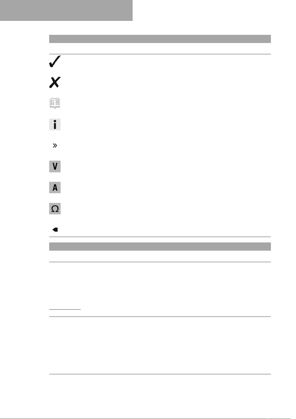
1.1 Symbols used
The meaning of specific symbols is described below.
Indicates an expected reaction (e.g. of a work step or a function).
Indicates an unexpected reaction (e.g. of a work step or a function).
Indicates a page reference (more information is provided on the specified page).
Indicates information with more details or tips.
Indicates the result of a testing step.
Indicates a voltage measurement.
Indicates a current measurement.
Indicates a resistance measurement.
Indicates the end of an activity including potential rework.
1.2 Formats used
The typographical formats used in this document are explained below.
Proprietary name Indicates a proprietary name.
®
Name
Brand™ Indicates a brand available on the open market.
Underlined terms Refer to technical details of the vehicle or indicate technical terms, which
Indicates a protected name.
are explained in the glossary.
2
Page 5
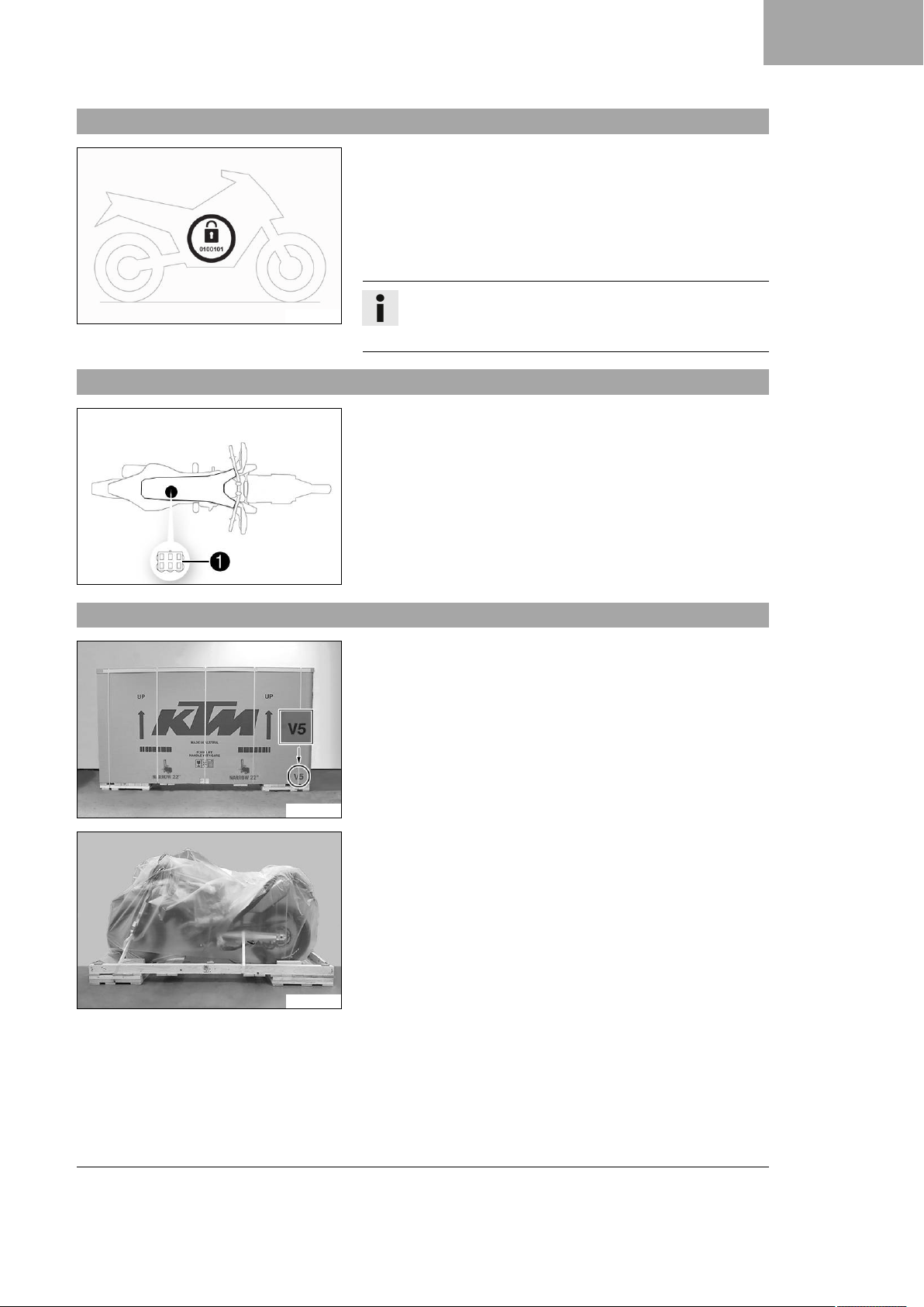
2.1 Transport mode
H02713-01
2.2 Diagnostics connector
SETUP 2
This vehicle was blocked for transport in the software.
To operate the vehicle, the vehicle electronics must be enabled.
This process is conducted during initial setup in KTM Dealer.net.
Enabling ensures that the initial setup in KTM Dealer.net is documented.
Enabling can be performed either temporarily, e.g. for a test ride,
or permanently for vehicle handover.
Info
Make sure that the vehicle is permanently enabled before
handing it over to the customer.
Diagnostics connector1is located under the engine electronics
control unit.
S02147-10
2.3 Unpacking and setting up the vehicle
– Remove the straps and the box.
S01530-10
– Remove the adhesive tape in the upper area of the motorcycle.
S03393-01
3
Page 6
2 SETUP
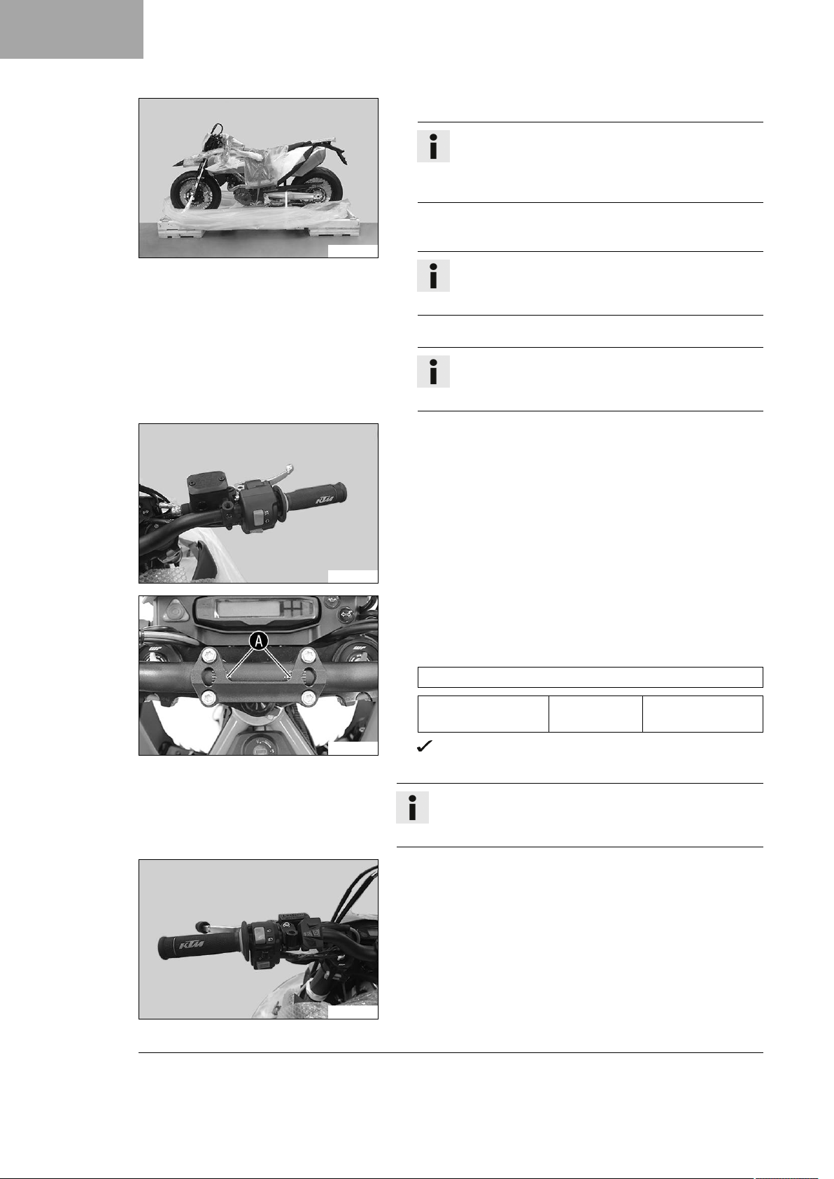
– Roll down the film at the sides.
Info
To avoid damaging the motorcycle during unpacking,
leave the other films on the vehicle until you have finished work on the vehicle.
– Remove the separate enclosure and unpack it. Check that the
separate enclosure is complete using the enclosed packing list.
S03394-01
Info
The procedure for missing components is described in
the Customer Service Manual.
– Check the vehicle for transport damage.
Info
The procedure in the event of transport damage is
described in the Customer Service Manual.
– Position the throttle grip and the controls of the right handle-
bar half on the handlebar.
– Mount the screws, but do not tighten them yet.
S03395-01
S04680-10
– Position the handlebar.
– Position the handlebar clamp. Mount the four screws and
tighten evenly.
Guideline
Mount the handlebar clamp as shown in the figure.
Screw, handlebar
clamp
The markingsAof the handlebar scale are located centrally between the handlebar clamp.
M8 20 Nm (14.8 lbf ft)
Info
The handlebar clamp is in the separate enclosure together
with the screws.
– Position the controls on the left handlebar half.
– Mount the screws, but do not tighten them yet.
S03397-01
4
Page 7
S03400-10
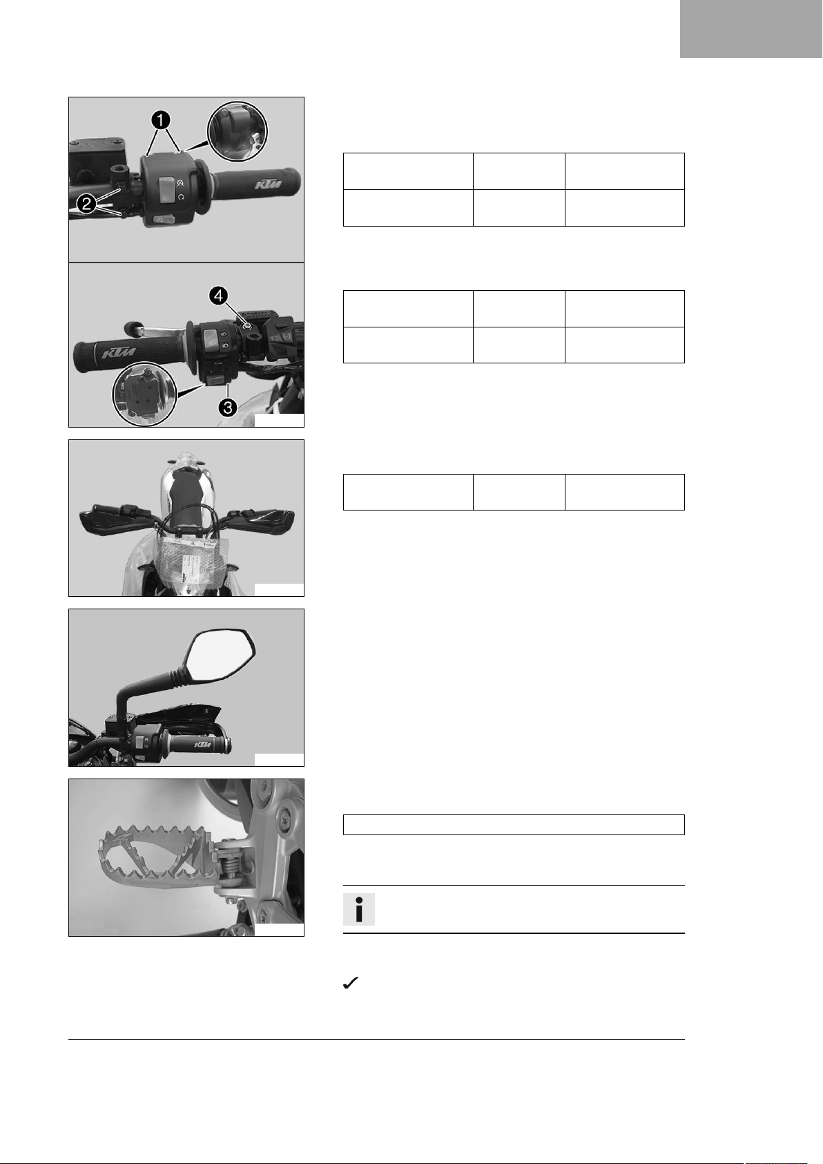
– Position all controls in their exact positions on the handlebar.
–
Tighten screws1and2.
Guideline
Screw, throttle grip M5 3.5 Nm
(2.58 lbf ft)
Screw, brake assem-
M6 5 Nm (3.7 lbf ft)
bly
– Check the throttle grip for smooth operation.
–
Tighten screws3and4.
Guideline
Screw, combination
switch, left
Screw, clutch assem-
M5 3.5 Nm
(2.58 lbf ft)
M6 5 Nm (3.7 lbf ft)
bly
SETUP 2
S03401-01
S03402-01
– Assemble the hand guards and mount on both sides.
Guideline
Handle bar end
M8 15 Nm (11.1 lbf ft)
screw
– Mount and tighten the rear mirror adapter and the rear mirror
on both sides.
– Mount the footrests with springs and pins. Secure the pins
using washers and cotter pins.
Footrest spring plier (58429083000)
100308-01
– Remove the protective film.
– Carefully loosen and remove the tension belt over the link fork.
Info
An assistant prevents the motorcycle from falling over.
– Carefully loosen and remove the tension belts around the lower
triple clamp.
The vehicle is released at the front.
– Together with an assistant, take the vehicle off the pallet.
5
Page 8
2 SETUP
S04681-10
– Charge the 12-V battery. ( p. 10)
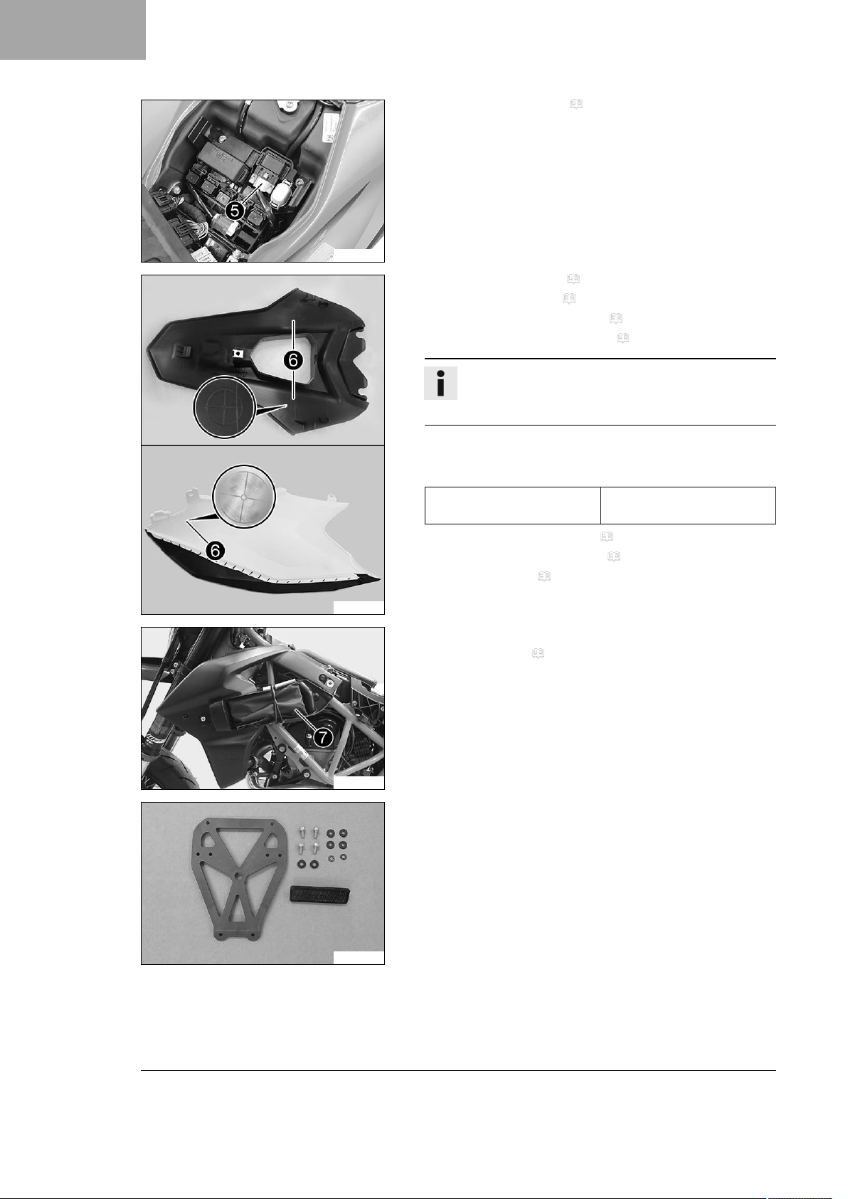
– Install the 12-V battery.
–
Plug in connector5on the starter relay.
–
Remove the rear fairing. ( p. 13)
– Take off the side cover. ( p. 13)
– Remove the rear left side cover. ( p. 14)
– Remove the rear right side cover. ( p. 14)
Info
A total of four markings6have been added to the
underside of the rear fairing and the two side covers.
– Drill the holes for the grab handle in three steps at these
points.
Guideline
Bore diameter for the grab
handle
14.5 mm (0.571 in)
S03406-10
S03411-10
– Install the rear left side cover. ( p. 15)
– Install the rear right side cover. ( p. 15)
– Fit the rear fairing. ( p. 16)
–
Store tool set7in the tool set compartment.
– Mount side cover. ( p. 16)
– Mount the reflector.
S03407-01
6
Page 9
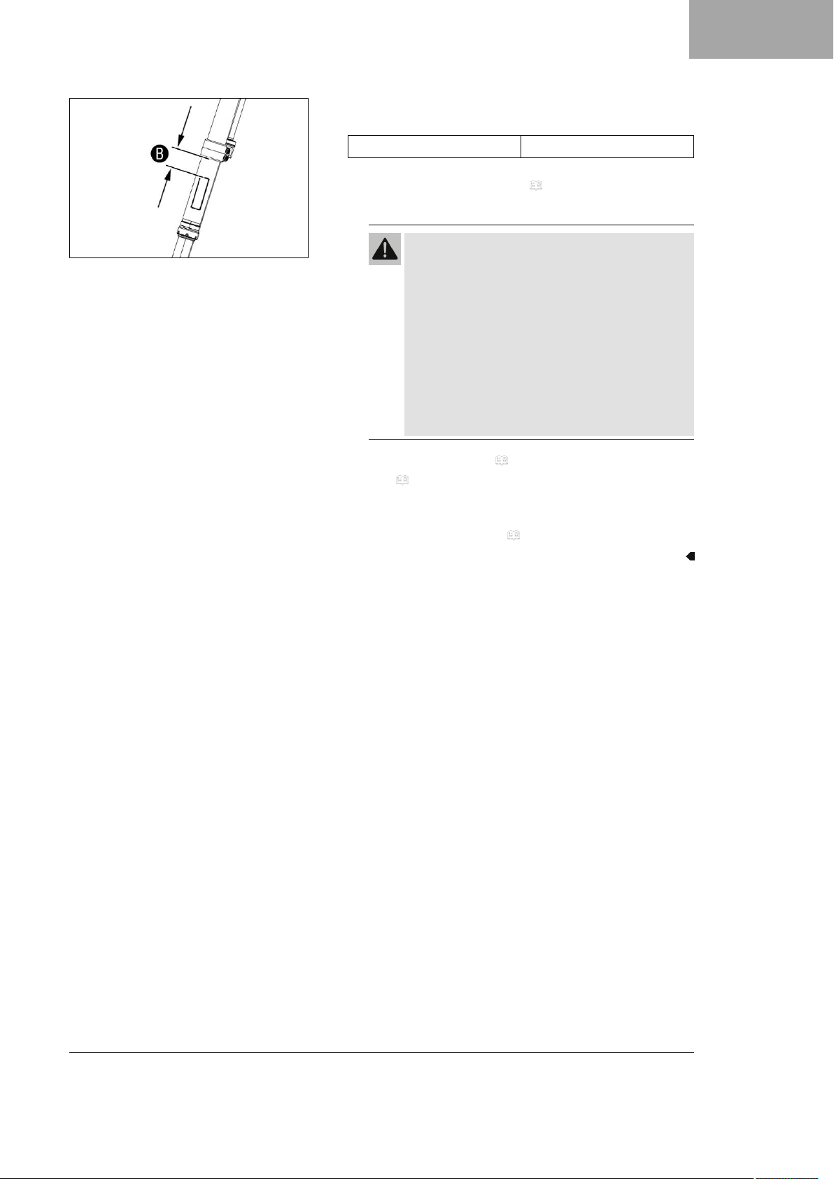
–
Mount the reflectors with distanceBon the fork.
Guideline
DistanceBfor reflectors
Operation as a 2-seater
– Mount rear footrest bracket. ( p. 17)
Operation as a 1-seater (only if requested by customer)
100 mm (3.94 in)
SETUP 2
S03408-01
Warning
Voiding of the government approval for road use and
the insurance coverage If the heel protector is fit-
ted instead of the footrest bracket, the vehicle no
longer conforms to the homologation.
The vehicle is homologated in the factory as 2seater.
– Set up the vehicle as standard as a 2-seater.
– If you set up the vehicle as a 1 seater, ensure
the change is entered in the registration papers
before preparing for use.
– Mount heel protector. ( p. 17)
– Refuel. ( p. 18)
– Prepare the vehicle according to the specifications in
KTM Dealer.net for handover to the customer.
– Set the kilometers or miles. ( p. 20)
7
Page 10
3 WORK
3.1 Removing the seat
3.2 Mounting the seat
S04383-10
Preparatory work
– Open the fuel tank filler cap. ( p. 12)
Main work
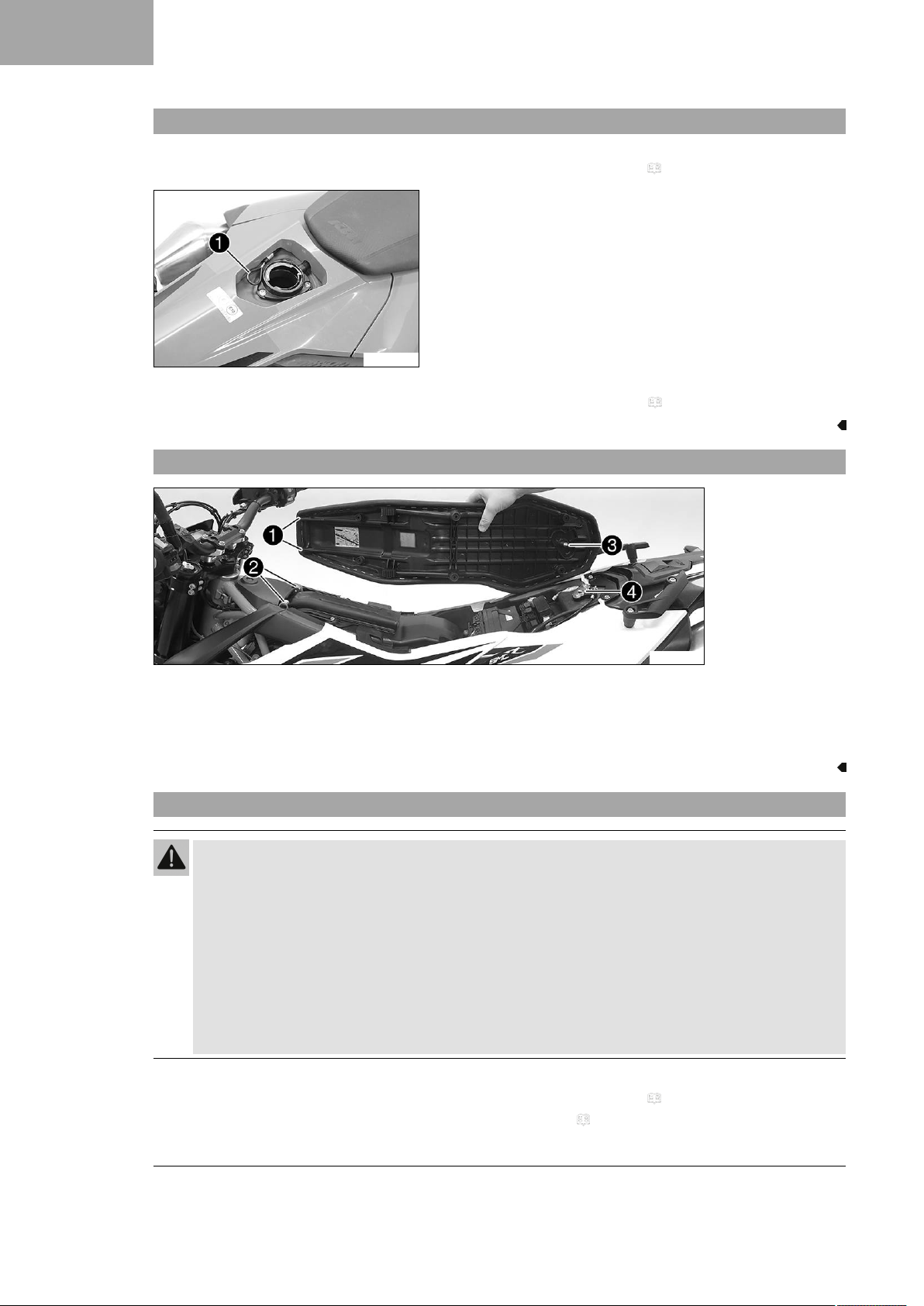
–
Pull on loop1and raise the rear of the seat.
– Pull the seat back and lift it off.
Finishing work
– Close the fuel tank filler cap. ( p. 12)
S03282-10
–
Hook the seat using holding lugs1on to bushings2, lower the seat at the rear and push it forward.
–
Push locking pin3into lock housing4and push the back of the seat down until the locking pin locks in
place with an audible click.
– Check that the seat is correctly mounted.
3.3 Removing the 12-V battery
Warning
Risk of injury Battery acid and battery gases cause serious chemical burns.
– Keep 12 V batteries out of the reach of children.
– Wear suitable protective clothing and safety glasses.
– Avoid contact with battery acid and battery gases.
– Keep sparks or open flames away from the 12 V battery.
– Only charge 12 V batteries in well-ventilated rooms.
– Rinse the affected area immediately with plenty of water in the event of contact with the skin.
– Rinse eyes with water for at least 15 minutes and consult a doctor immediately if battery acid and
battery gases get into the eyes.
Preparatory work
– Open the fuel tank filler cap. ( p. 12)
–
Remove the seat. ( p. 8)
8
Page 11
Main work
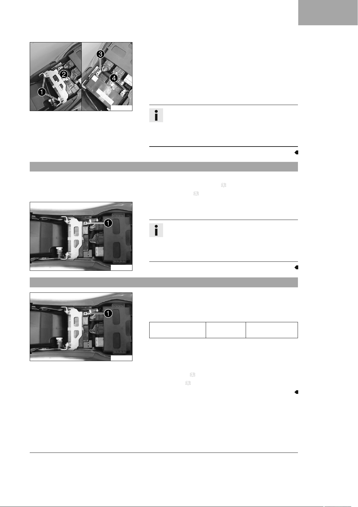
–
Remove screws1.
– Push the retaining bracket toward the rear and remove it.
–
Take off positive terminal cover2.
–
Disconnect negative cable3from the 12-V battery.
–
Disconnect positive cable4from the 12-V battery.
– Lift out the 12-V battery.
WORK 3
S04390-10
3.4 Disconnecting the 12-V battery
D07481-10
Info
Never operate the motorcycle with a discharged 12-V
battery or without a 12-V battery. In both cases, electrical components and safety devices can be damaged.
The vehicle will therefore no longer be roadworthy.
Preparatory work
– Open the fuel tank filler cap. ( p. 12)
– Remove the seat. ( p. 8)
Main work
–
Disconnect negative cable1of the 12-V battery.
Info
Never operate the motorcycle with a discharged 12-V
battery or without a 12-V battery. In both cases, electrical components and safety devices can be damaged.
The vehicle will therefore no longer be roadworthy.
3.5 Connecting the 12-V battery
D07481-10
Main work
–
Position washer and negative cable1, and mount and
tighten the screw.
Guideline
Screw, battery terminal
Finishing work
– Mount the seat. ( p. 8)
– Set the clock. ( p. 19)
M6 4.5 Nm
(3.32 lbf ft)
9
Page 12
3 WORK
3.6 Charging the 12-V battery
Warning
Risk of injury Battery acid and battery gases cause serious chemical burns.
– Keep 12 V batteries out of the reach of children.
– Wear suitable protective clothing and safety glasses.
– Avoid contact with battery acid and battery gases.
– Keep sparks or open flames away from the 12 V battery.
– Only charge 12 V batteries in well-ventilated rooms.
– Rinse the affected area immediately with plenty of water in the event of contact with the skin.
– Rinse eyes with water for at least 15 minutes and consult a doctor immediately if battery acid and
battery gases get into the eyes.
Note
Environmental hazard 12 V batteries contain environmentally hazardous materials.
– Do not dispose of 12 V batteries as household waste.
– Dispose of 12 V batteries at a collection point for used batteries.
Note
Environmental hazard Hazardous substances cause environmental damage.
– Dispose of oils, grease, filters, fuel, cleaning agents, brake fluid, etc., correctly and in compliance with
the applicable regulations.
Info
Even when there is no load on the 12-V battery, it discharges steadily each day.
The charging level and the method of charging are very important for the service life of the 12-V battery.
Rapid recharging with a high charging current shortens the service life of the battery.
If the charging current, charging voltage, and charging time are exceeded, the 12-V battery will be
destroyed.
If the 12-V battery is depleted from starting the vehicle repeatedly, the battery must be charged immediately.
If the 12-V battery is left in a discharged state for an extended period, it will become deeply discharged
and sulfating occurs, destroying the battery.
The 12-V battery is maintenance-free, i.e. the acid level does not have to be checked.
Preparatory work
– Open the fuel tank filler cap. ( p. 12)
– Remove the seat. ( p. 8)
– Disconnect the 12-V battery. ( p. 9)
Main work
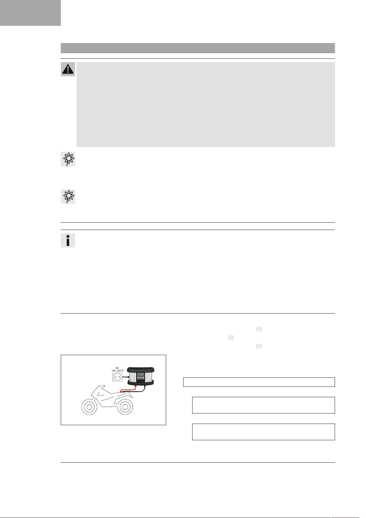
– Connect a battery charger to the 12-V battery. Adjust the bat-
tery charger.
EU battery charger XCharge‑professional (00029095050)
Alternative 1
US battery charger XCharge‑professional
(00029095051)
10
311910-10
Alternative 2
UK battery charger XCharge‑professional
(00029095052)
Page 13
3.7 Installing the 12-V battery
Info
Follow the instructions of the charger and the manual.
– Disconnect the battery charger after charging the 12-V battery.
Guideline
The charging current, charging voltage, and charging time
must not be exceeded.
Recharge the 12-V battery
regularly when the motorcycle is not being used
Finishing work
– Connect the 12-V battery. ( p. 9)
–
Mount the seat. ( p. 8)
– Set the clock. ( p. 19)
Main work
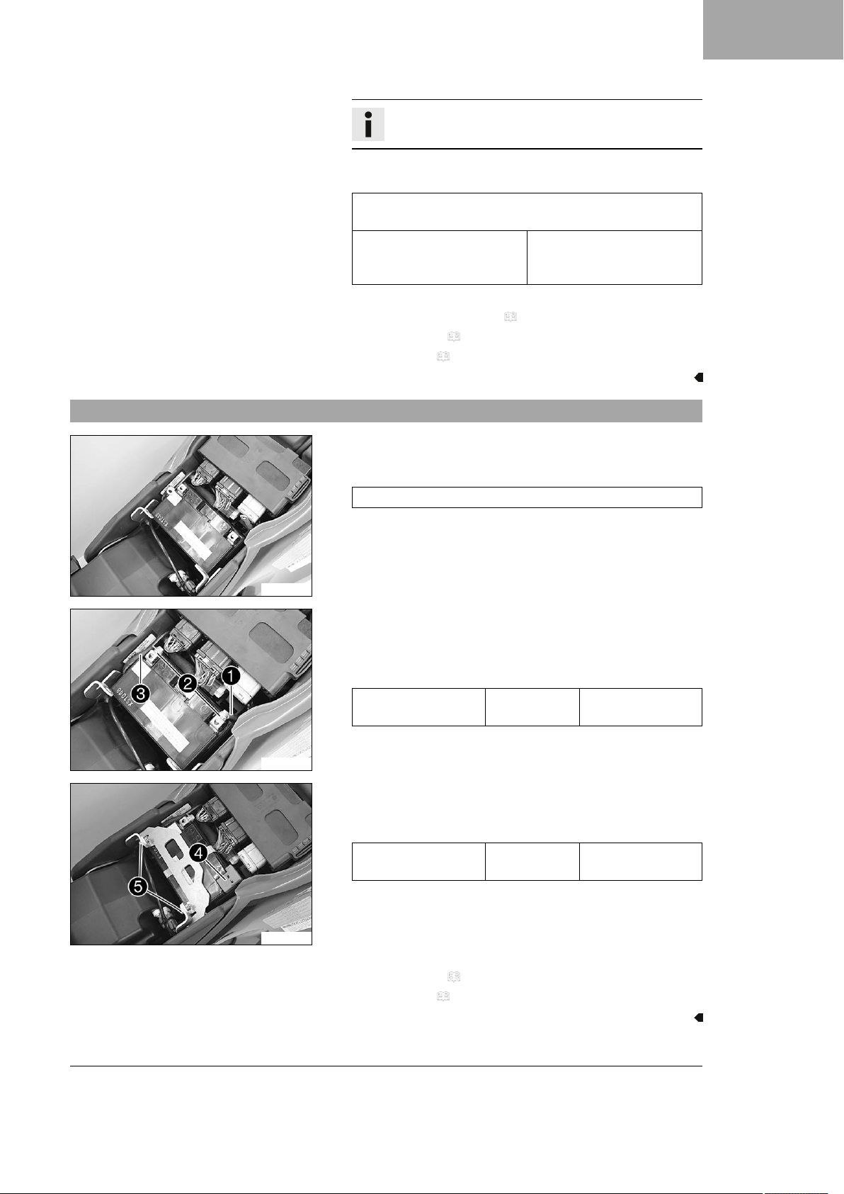
– Insert the 12-V battery into the battery compartment with the
terminals facing to the rear.
3 months
WORK 3
S04391-01
S04392-10
12-V battery (YTZ10S)
–
Position positive cable1with washer2.
–
Position negative cable3with washer2.
– Mount and tighten the screw.
Guideline
Screw, battery terminal
–
Position positive terminal cover4.
–
Position retaining bracket and mount and tighten screws5.
Guideline
Remaining screws,
chassis
M6 4.5 Nm
(3.32 lbf ft)
M6 10 Nm (7.4 lbf ft)
S04393-10
Finishing work
– Mount the seat. ( p. 8)
– Set the clock. ( p. 19)
11
Page 14
3 WORK
3.8 Opening the fuel tank filler cap
Danger
Fire hazard Fuel is highly flammable.
The fuel in the fuel tank expands when warm and can escape if overfilled.
– Do not fuel the vehicle in the vicinity of open flames or lit cigarettes.
– Switch off the engine for refueling.
– Make sure that no fuel is spilled; particularly not on hot parts of the vehicle.
– If any fuel is spilled, wipe it off immediately.
– Observe the specifications for refueling.
Warning
Danger of poisoning Fuel is poisonous and a health hazard.
– Avoid skin, eye and clothing contact with fuel.
– Immediately consult a doctor if you swallow fuel.
– Do not inhale fuel vapors.
– In case of skin contact, rinse the affected area with plenty of water.
– Rinse the eyes thoroughly with water, and consult a doctor in case of fuel contact with the eyes.
– Change your clothing in case of fuel spills on them.
– Keep fuels correctly in a suitable canister, and out of the reach of children.
Note
Environmental hazard Improper handling of fuel is a danger to the environment.
– Do not allow fuel to enter the groundwater, the soil, or the sewage system.
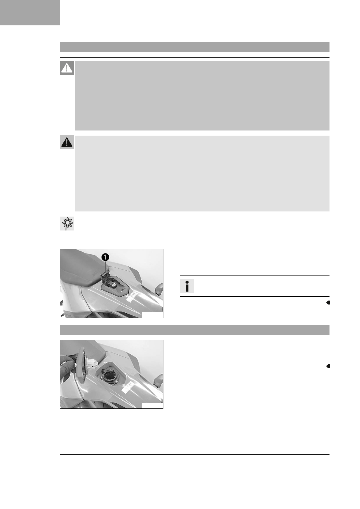
–
Lift cover1of fuel tank filler cap and insert the ignition key.
– Turn the ignition key 90° counterclockwise and take off the
fuel tank filler cap.
Info
The fuel tank filler cap has a fuel tank breather.
S04577-10
3.9 Closing the fuel tank filler cap
– Put the fuel tank filler cap back on and turn the ignition key
90° clockwise.
– Remove the ignition key and close the cover.
12
S04578-01
Page 15
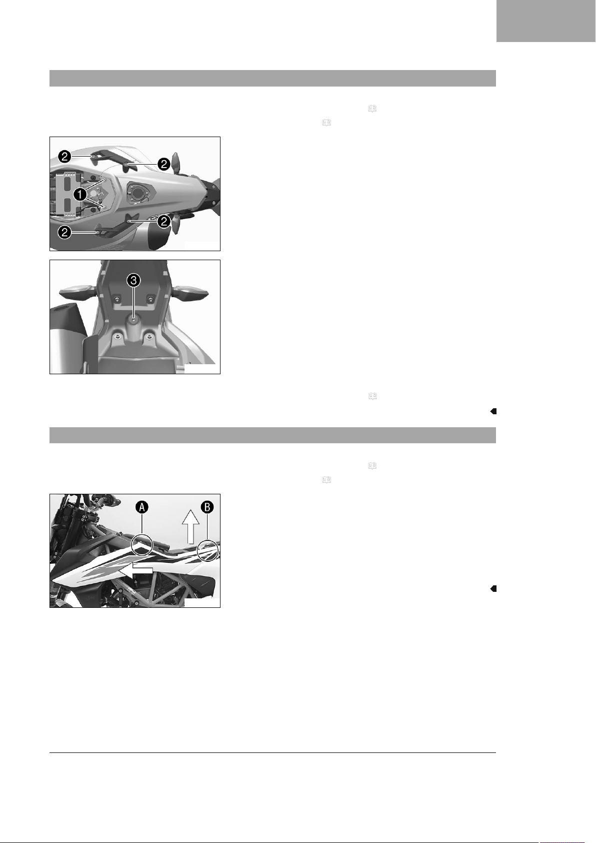
3.10 Removing the rear fairing
D07483-10
Preparatory work
– Open the fuel tank filler cap. ( p. 12)
– Remove the seat. ( p. 8)
Main work
–
Remove screws1with the bushings.
–
Remove screws2and take off the grab handle.
–
Remove screw3.
– Take off the rear fairing.
WORK 3
D07484-10
3.11 Take off the side cover
S03283-10
Finishing work
– Close the fuel tank filler cap. ( p. 12)
Preparatory work
– Open the fuel tank filler cap. ( p. 12)
– Remove the seat. ( p. 8)
Main work
– Remove the left side cover from the rubber bushing in area
.
A
– Remove the left side cover upwards from the bushing in area
.
B
– Take off the left side cover from the front.
– Repeat these steps on the opposite side.
13
Page 16
3 WORK
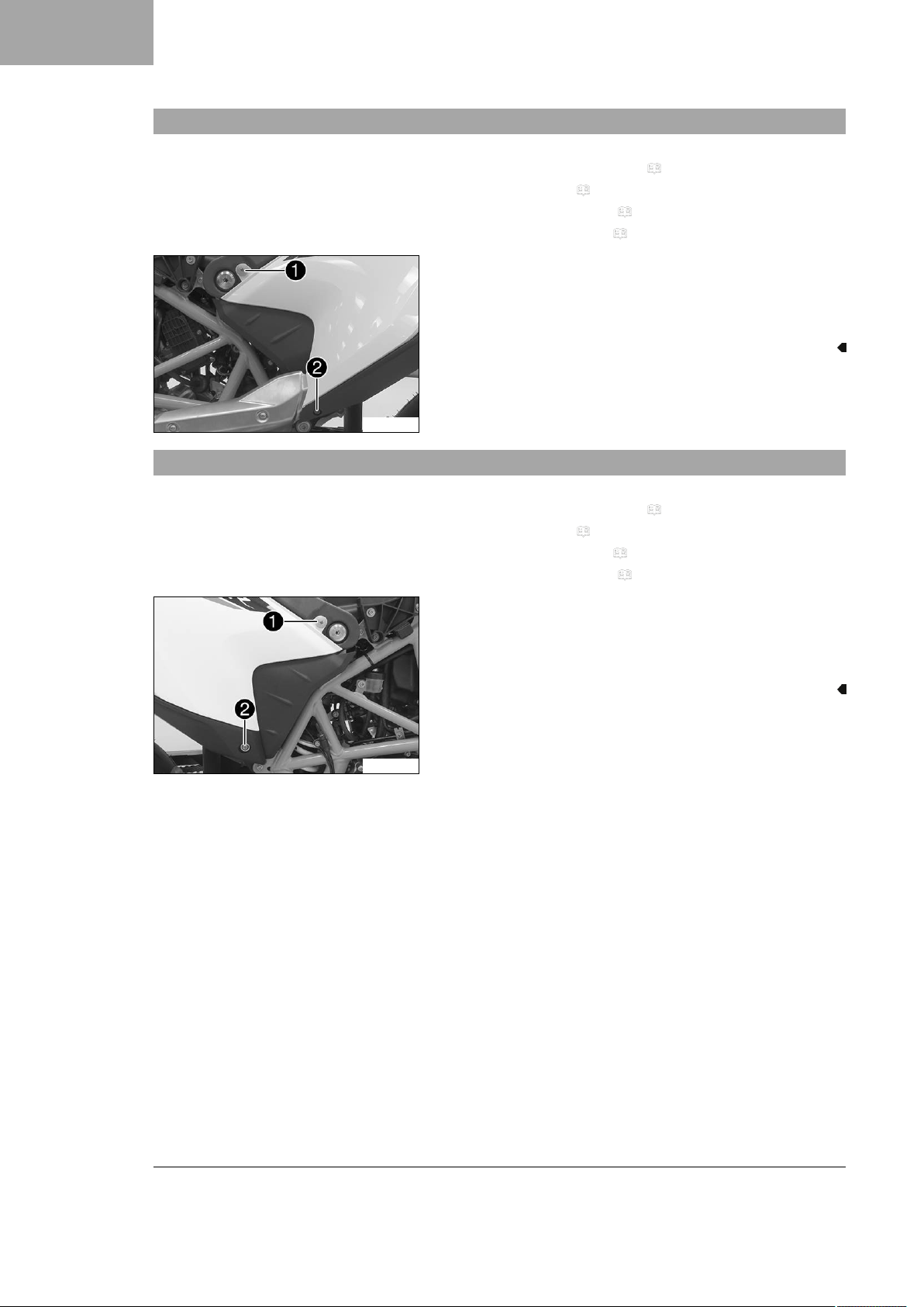
3.12 Removing the rear left side cover
Preparatory work
– Open the fuel tank filler cap. ( p. 12)
– Remove the seat. ( p. 8)
– Remove the rear fairing. ( p. 13)
– Take off the side cover. ( p. 13)
Main work
–
–
– Take off the side cover.
R05344-10
3.13 Removing the rear right side cover
Remove screw1.
Remove screw2.
R05343-10
Preparatory work
– Open the fuel tank filler cap. ( p. 12)
– Remove the seat. ( p. 8)
– Take off the side cover. ( p. 13)
– Remove the rear fairing. ( p. 13)
Main work
–
Remove screw1.
–
Remove screw2with the bushing.
– Take off the side cover.
14
Page 17
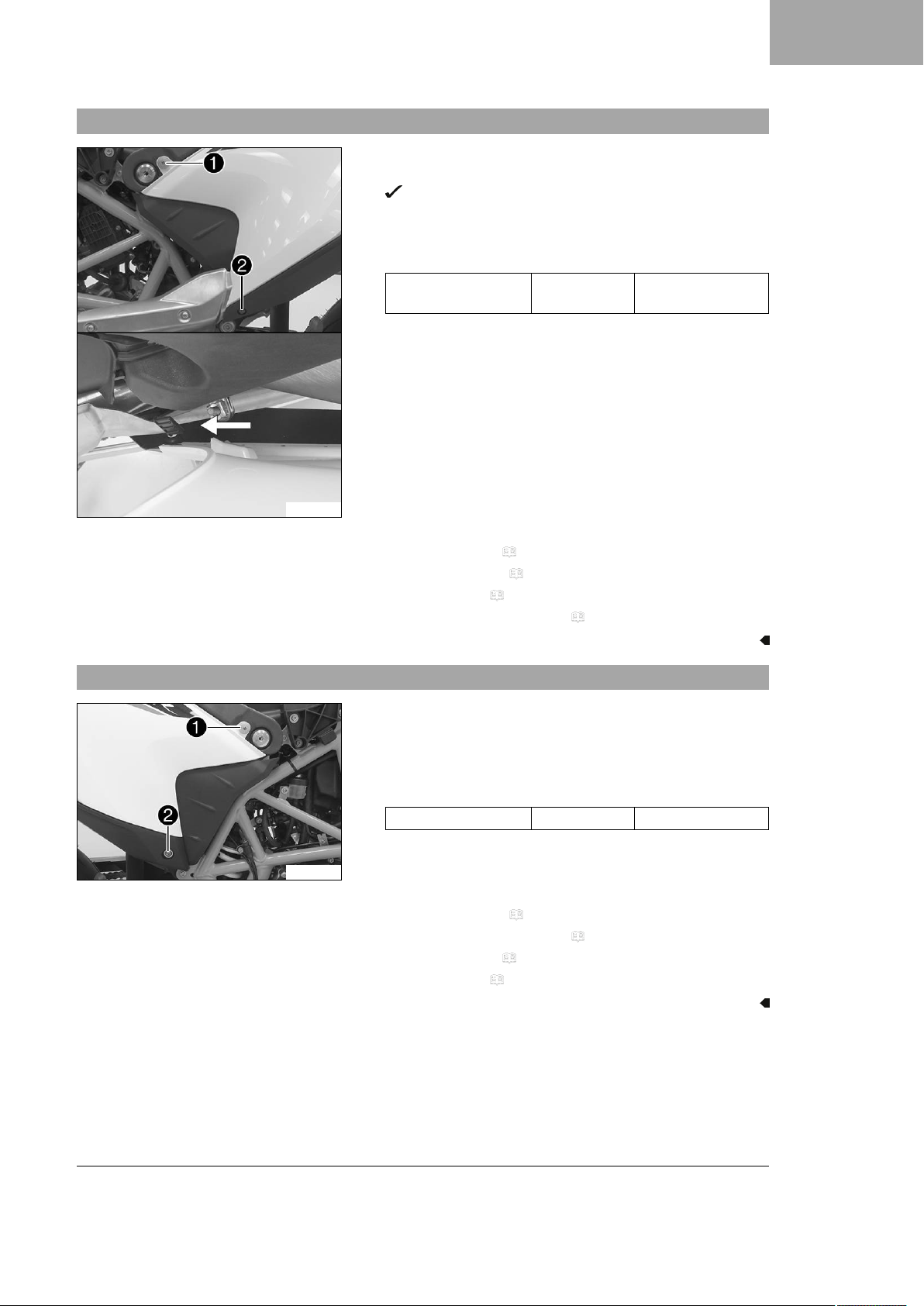
3.14 Installing the rear left side cover
Main work
– Mount the trim.
–
–
The trim engages in the bracket.
Mount and tighten screw1.
Mount and tighten screw2.
Guideline
Remaining screws,
chassis
M5 5 Nm (3.7 lbf ft)
WORK 3
R05345-10
Finishing work
– Mount side cover. ( p. 16)
– Fit the rear fairing. ( p. 16)
– Mount the seat. ( p. 8)
– Close the fuel tank filler cap. ( p. 12)
3.15 Installing the rear right side cover
Main work
– Mount side cover.
–
–
R05343-10
Finishing work
– Fit the rear fairing. ( p. 16)
– Close the fuel tank filler cap. ( p. 12)
– Mount side cover. ( p. 16)
– Mount the seat. ( p. 8)
Mount and tighten screw1.
Mount and tighten screw2with the bushing.
Guideline
Screw, seat support M6x12 5 Nm (3.7 lbf ft)
15
Page 18
3 WORK
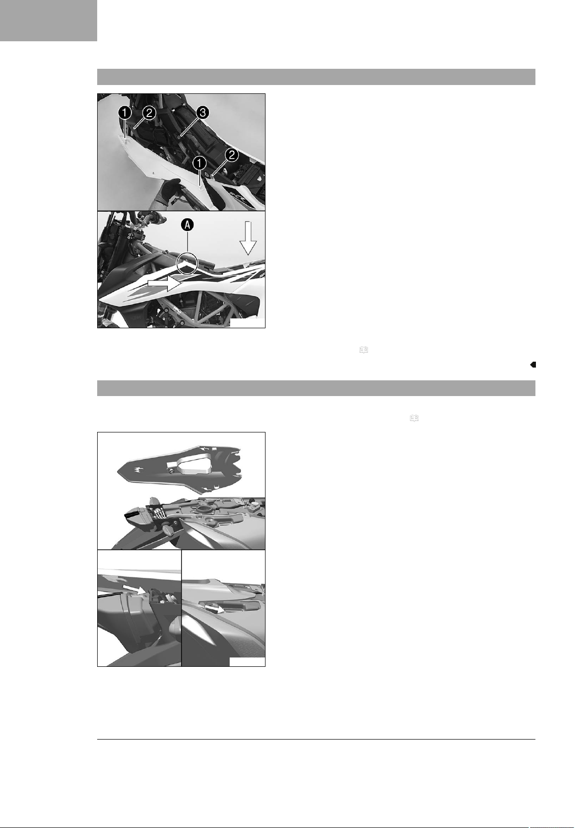
3.16 Mounting side cover
Main work
–
Position the left side cover using holding lugs1on bushings
and push towards the rear and, in the rear section, down-
2
ward.
–
Press the left side cover into the rubber bushing3in area
.
A
– Repeat these steps on the opposite side.
3.17 Fitting the rear fairing
S03288-10
Finishing work
– Mount the seat. ( p. 8)
Preparatory work
– Open the fuel tank filler cap. ( p. 12)
Main work
– Slip in the rear fairing and position it.
16
D07485-10
Page 19
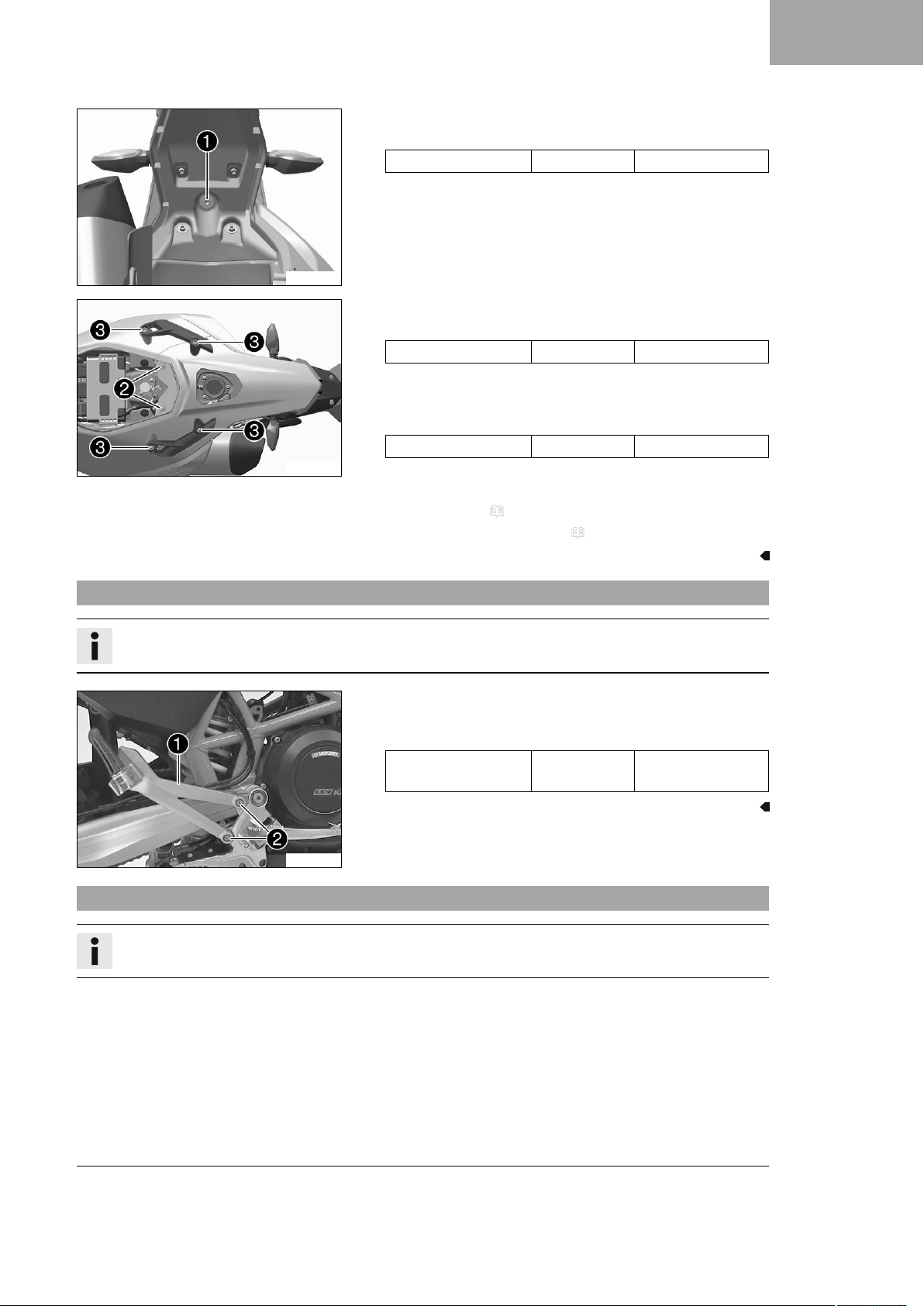
D07484-11
D07483-11
–
Mount and tighten screw1.
Guideline
Screw, tail section M6x21 10 Nm (7.4 lbf ft)
–
Mount screws2with the bushings and tighten.
Guideline
Screw, trim M5x20 2 Nm (1.5 lbf ft)
– Position the grab handle.
–
Mount and tighten screws3.
Guideline
Screw, grab handle M8 10 Nm (7.4 lbf ft)
WORK 3
Finishing work
– Mount the seat. ( p. 8)
– Close the fuel tank filler cap. ( p. 12)
3.18 Mounting rear footrest bracket
Info
The operations are the same for the left and right sides.
–
S00784-10
3.19 Mounting heel protector
Info
The operations are the same for the left and right sides.
Position the footrest bracket1. Mount and tighten
screws2.
Guideline
Screw, rear footrest
bracket
M8x16 25 Nm (18.4 lbf ft)
17
Page 20
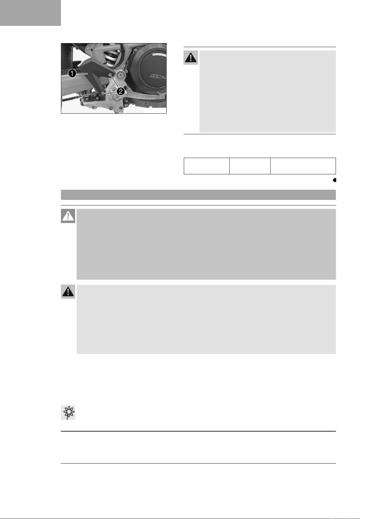
3 WORK
S00808-10
Warning
Voiding of the government approval for road use and
the insurance coverage If the heel protector is fitted
instead of the footrest bracket, the vehicle no longer
conforms to the homologation.
The vehicle is homologated in the factory as 2-seater.
– Set up the vehicle as standard as a 2-seater.
– If you set up the vehicle as a 1 seater, ensure the
change is entered in the registration papers before
preparing for use.
–
Position the heel protector1. Mount and tighten screws2.
Guideline
Screw, heel protector
M8x12 5 Nm (3.7 lbf ft)
Loctite®243™
3.20 Refueling
Danger
Fire hazard Fuel is highly flammable.
The fuel in the fuel tank expands when warm and can escape if overfilled.
– Do not fuel the vehicle in the vicinity of open flames or lit cigarettes.
– Switch off the engine for refueling.
– Make sure that no fuel is spilled; particularly not on hot parts of the vehicle.
– If any fuel is spilled, wipe it off immediately.
– Observe the specifications for refueling.
Warning
Danger of poisoning Fuel is poisonous and a health hazard.
– Avoid skin, eye and clothing contact with fuel.
– Immediately consult a doctor if you swallow fuel.
– Do not inhale fuel vapors.
– In case of skin contact, rinse the affected area with plenty of water.
– Rinse the eyes thoroughly with water, and consult a doctor in case of fuel contact with the eyes.
– Change your clothing in case of fuel spills on them.
Note
Material damage Inadequate fuel quality causes the fuel filter to quickly become clogged.
In some countries and regions, the available fuel quality and cleanliness may not be sufficient. This will result in
problems with the fuel system.
– Refuel only with clean fuel that meets the specified standards.
Note
Environmental hazard Improper handling of fuel is a danger to the environment.
–
Do not allow fuel to enter the groundwater, the soil, or the sewage system.
18
Page 21
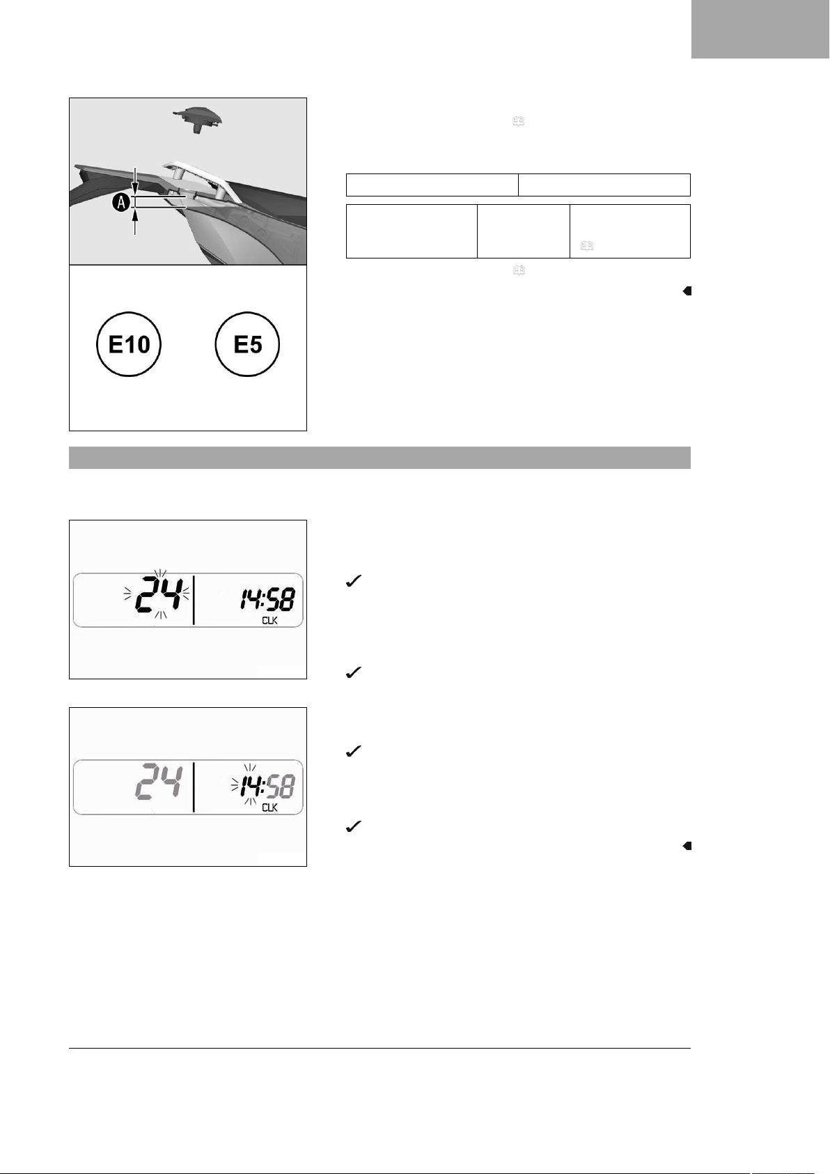
– Switch off the engine.
– Open the fuel tank filler cap. ( p. 12)
–
Fill the fuel tank with fuel up to levelA.
Guideline
Dimension
A
20 mm (0.79 in)
WORK 3
3.21 Setting the clock
S03345-10
S04363-01
Fuel tank capacity,
approx.
– Close the fuel tank filler cap. ( p. 12)
Condition
The motorcycle is stationary.
– Press the + or ‑ button until the indicator CLK appears in the
combination instrument.
– Press and hold the ‑ button for 3-5 seconds.
The combination instrument switches to the clock setting
mode.
– Press the ‑ button to select the 24 h display or 12 h display
for the clock.
– Confirm the selection using the + button.
The setting is adopted and the combination instrument
changes to the next menu item.
– Press the ‑ button to set the hour.
– Confirm the selection using the + button.
The setting is adopted and the combination instrument
changes to the next menu item.
– Press the ‑ button to set the minute.
– Confirm the selection using the + button.
The setting is adopted and the setting mode is closed.
13.5 l
(3.57 US gal)
Super unleaded
(ROZ 95)
( p. 24)
S04367-01
19
Page 22
3 WORK
3.22 Setting kilometers or miles
Info
If the unit is changed, the value is retained and converted accordingly.
Make the setting according to the country.
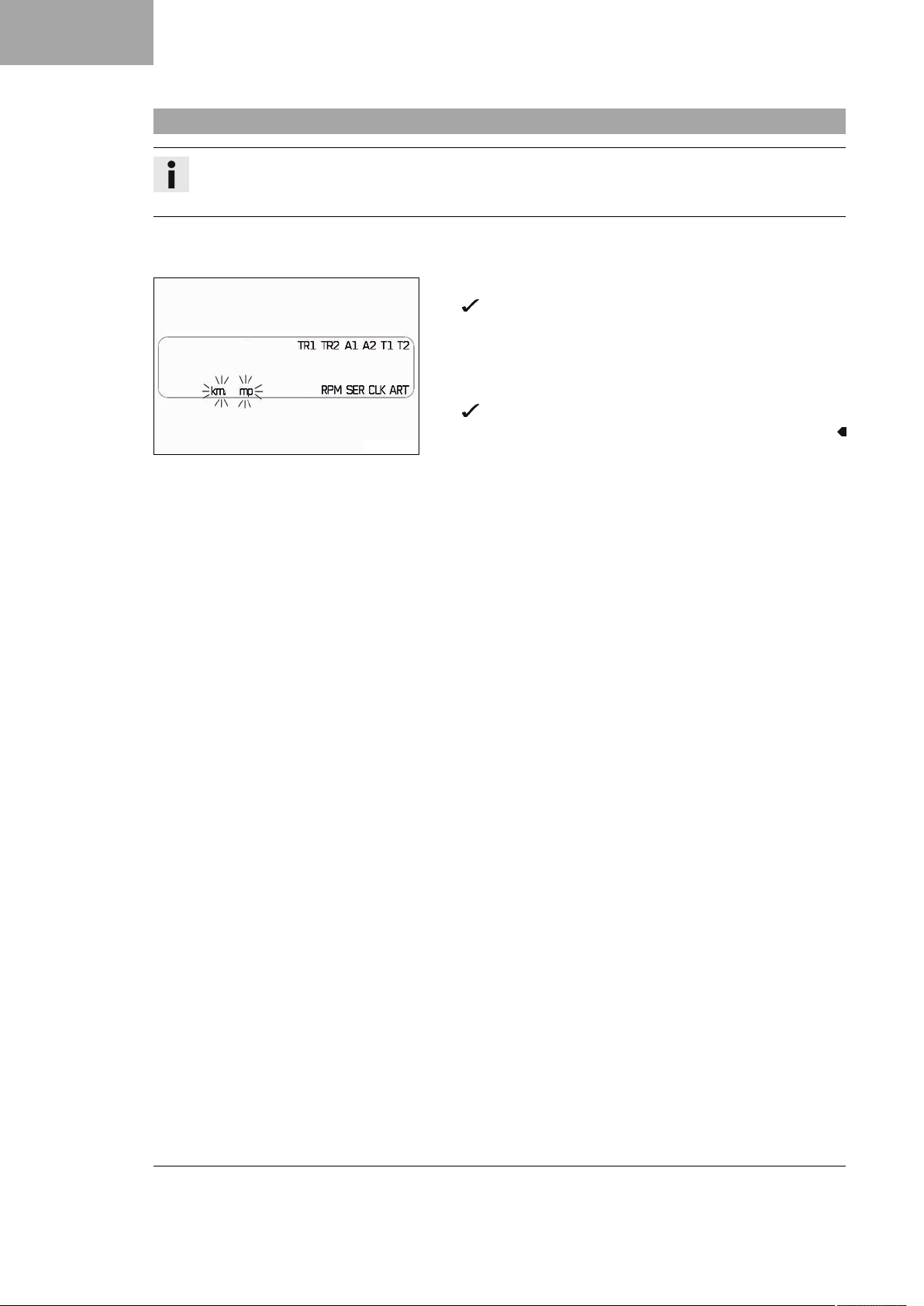
Condition
The motorcycle is stationary.
– Press and hold both buttons for 3 – 5 seconds.
The Setup menu is displayed.
– Press the + button repeatedly until kmor mp flashes on the
indicator.
– Press the ‑ button to change from km to mp or from mp to km.
– Press the + button.
The settings are adopted and the setup menu is closed.
S04361-01
20
Page 23
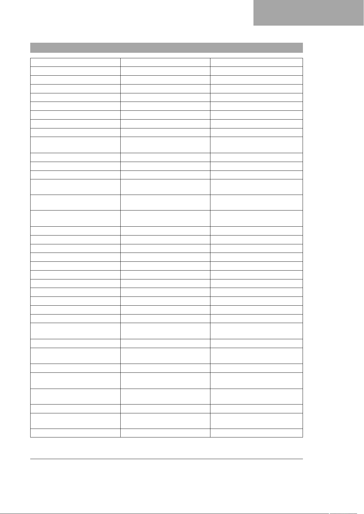
4.1 Chassis tightening torques
Screw, chain guard EJOT 1.5 Nm (1.11 lbf ft)
Screw, combination instrument EJOT 1 Nm (0.7 lbf ft)
Screw, side cover on spoiler EJOT 2 Nm (1.5 lbf ft)
Screw, side stand sensor EJOT 1 Nm (0.7 lbf ft)
Fitting, side stand sensor M4 2 Nm (1.5 lbf ft)
Spoke nipple, front wheel M4.5 4 Nm (3 lbf ft)
Spoke nipple, rear wheel M4.5 4 Nm (3 lbf ft)
Remaining nuts, chassis M5 5 Nm (3.7 lbf ft)
Remaining screws, chassis M5 5 Nm (3.7 lbf ft)
Screw, brake line holder on link
fork
Screw, cable on starter motor M5 3 Nm (2.2 lbf ft)
Screw, combination switch, left M5 3.5 Nm (2.58 lbf ft)
Screw, electrical holder M5 3 Nm (2.2 lbf ft)
Screw, exhaust heat shield M5 8 Nm (5.9 lbf ft)
Screw, foot brake lever stub M5 6 Nm (4.4 lbf ft)
Screw, fuel hose clamp on fuel
tank
Screw, fuel level sensor M5 3 Nm (2.2 lbf ft)
Screw, fuel pump M5 4 Nm (3 lbf ft)
Screw, fuel tank closure flange M5 2.5 Nm (1.84 lbf ft)
Screw, headlight mask M5 2 Nm (1.5 lbf ft)
Screw, pressure regulator M5 4 Nm (3 lbf ft)
Screw, radiator fan cover M5 3.2 Nm (2.36 lbf ft)
Screw, radiator guard M5 3.5 Nm (2.58 lbf ft)
Screw, throttle grip M5 3.5 Nm (2.58 lbf ft)
Remaining nuts, chassis M6 10 Nm (7.4 lbf ft)
Remaining screws on fuel tank M6 5 Nm (3.7 lbf ft)
Remaining screws, chassis M6 10 Nm (7.4 lbf ft)
Screw connection, foot brake cylin-
der
Screw, ABS control unit M6 5 Nm (3.7 lbf ft)
Screw, ball joint of push rod on
foot brake cylinder
Screw, brake assembly M6 5 Nm (3.7 lbf ft)
Screw, brake fluid reservoir for rear
brake
Screw, chain guard M6 2 Nm (1.5 lbf ft)
Screw, chain guide M6 10 Nm (7.4 lbf ft)
Screw, chain sliding guard M6 10 Nm (7.4 lbf ft)
Screw, clutch assembly M6 5 Nm (3.7 lbf ft)
M5 5 Nm (3.7 lbf ft)
M5 5 Nm (3.7 lbf ft)
M6 10 Nm (7.4 lbf ft)
M6 10 Nm (7.4 lbf ft)
M6 5 Nm (3.7 lbf ft)
TECHNICAL DATA 4
Loctite®243™
Loctite®243™
Loctite®243™
Loctite®243™
Loctite®243™
21
Page 24
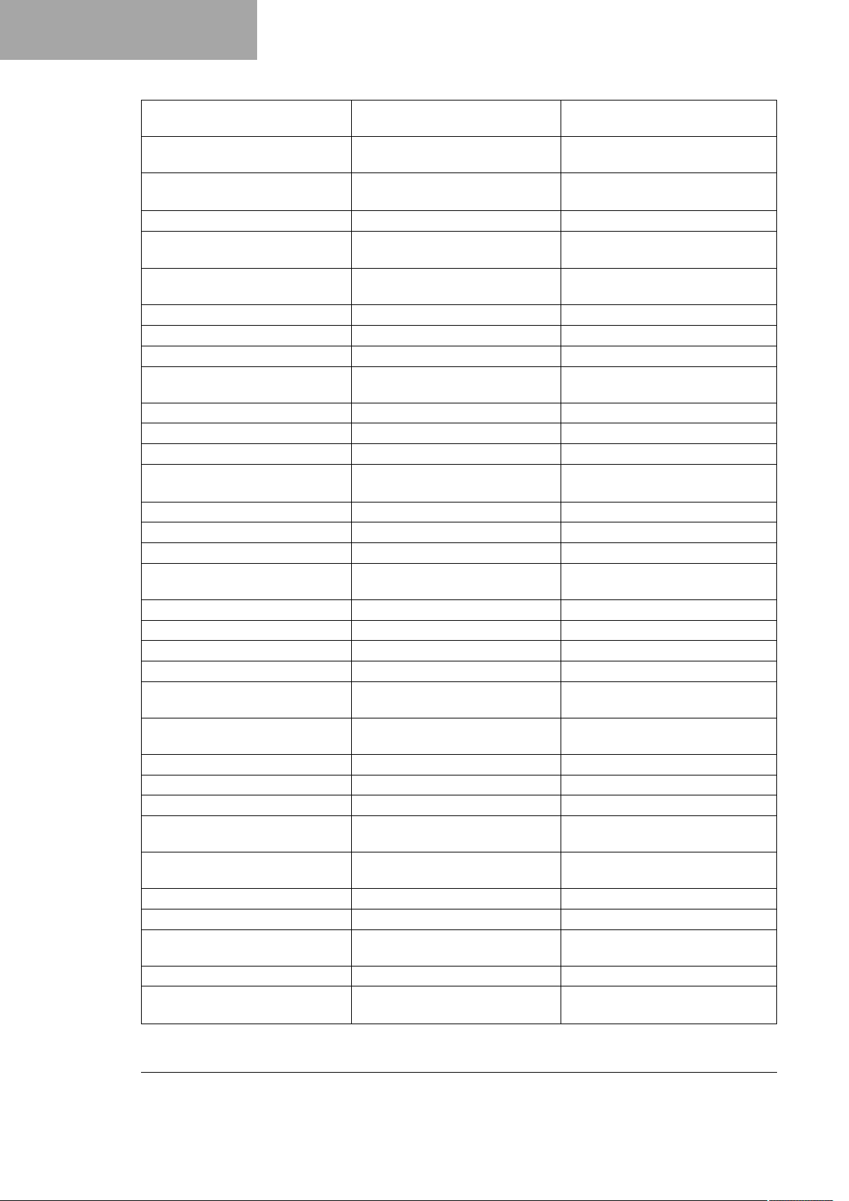
4 TECHNICAL DATA
Screw, front brake disc M6 14 Nm (10.3 lbf ft)
Screw, ignition lock M6 10 Nm (7.4 lbf ft)
Screw, license plate holder, bottom
Screw, license plate holder, top M6 8 Nm (5.9 lbf ft)
Screw, magnetic holder on side
stand
Screw, main silencer clamp M6 10 Nm (7.4 lbf ft)
Screw, radiator bleeding M6 8 Nm (5.9 lbf ft)
Screw, radiator bracket, bottom M6 8 Nm (5.9 lbf ft)
Screw, radiator bracket, top M6 10 Nm (7.4 lbf ft)
Screw, rear brake disc M6 14 Nm (10.3 lbf ft)
Screw, right side cover M6x12 5 Nm (3.7 lbf ft)
Screw, SAS valve M6 4 Nm (3 lbf ft)
Screw, seat lock M6 5 Nm (3.7 lbf ft)
Screw, upper part of the air filter
box
Screw, voltage regulator M6 8 Nm (5.9 lbf ft)
Screw, wheel speed sensor M6 6 Nm (4.4 lbf ft)
Handle bar end screw M8 15 Nm (11.1 lbf ft)
Nut, rear sprocket screw M8 35 Nm (25.8 lbf ft)
Remaining nuts, chassis M8 25 Nm (18.4 lbf ft)
Remaining screws, chassis M8 25 Nm (18.4 lbf ft)
Screw, bottom triple clamp M8 12 Nm (8.9 lbf ft)
Screw, chain sliding piece M8 15 Nm (11.1 lbf ft)
Screw, connection lever on frame M8 30 Nm (22.1 lbf ft)
Screw, foot brake lever M8 25 Nm (18.4 lbf ft)
Screw, fork stub M8 15 Nm (11.1 lbf ft)
Screw, front footrest bracket M8 25 Nm (18.4 lbf ft)
Screw, fuel tank bracket M8 15 Nm (11.1 lbf ft)
Screw, fuel tank, bottom M8 25 Nm (18.4 lbf ft)
Screw, fuel tank, top M8 25 Nm (18.4 lbf ft)
Screw, grab handle M8 10 Nm (7.4 lbf ft)
Screw, handlebar clamp M8 20 Nm (14.8 lbf ft)
Screw, heel protector M8x12 5 Nm (3.7 lbf ft)
Screw, main silencer holder M8 25 Nm (18.4 lbf ft)
Screw, main silencer holder on
fuel tank
Loctite®243™
Loctite®243™
M6 8 Nm (5.9 lbf ft)
M6 6 Nm (4.4 lbf ft)
Loctite®243™
Copper paste
Loctite®243™
M6 2 Nm (1.5 lbf ft)
Loctite®2701™
Loctite®243™
Loctite®243™
Loctite®243™
Loctite®243™
Loctite®243™
M8 25 Nm (18.4 lbf ft)
22
Page 25
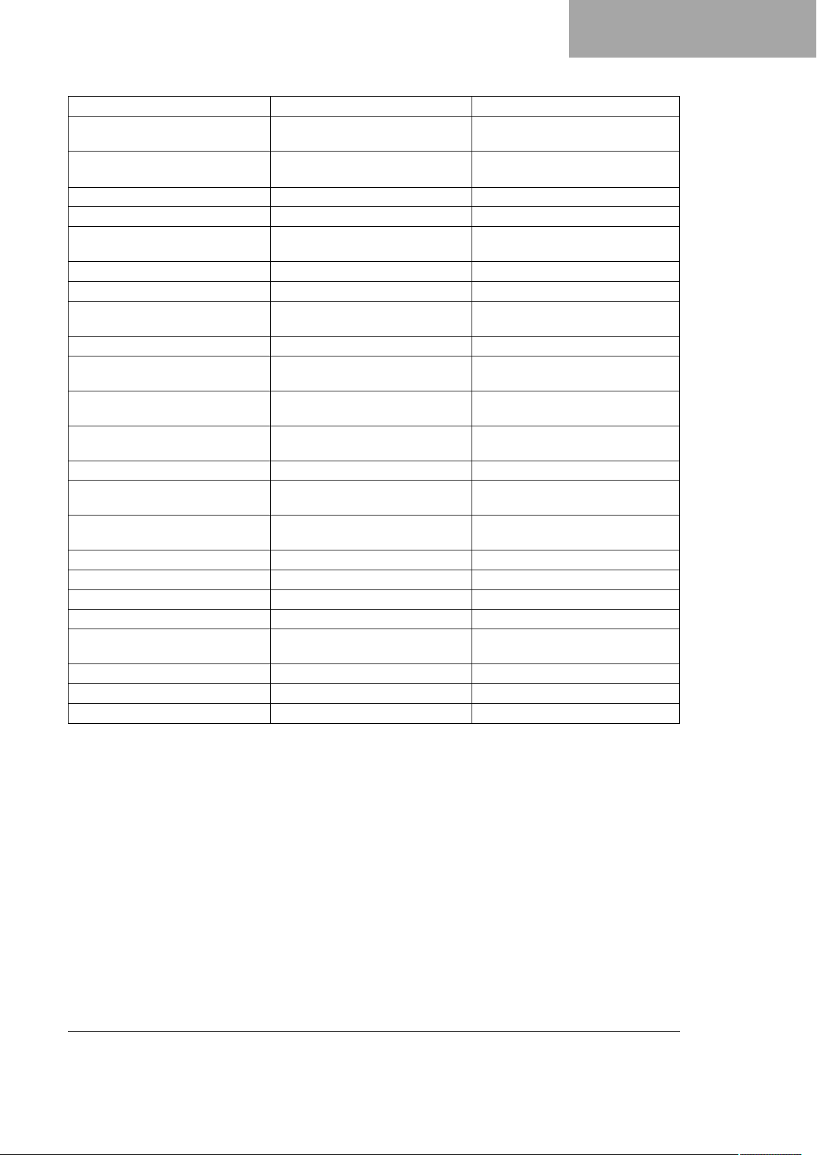
Screw, rear footrest bracket M8x16 25 Nm (18.4 lbf ft)
Screw, side stand bracket M8 25 Nm (18.4 lbf ft)
Screw, spring holder plate on side
stand bracket
Screw, steering stem M8 20 Nm (14.8 lbf ft)
Screw, top triple clamp M8 17 Nm (12.5 lbf ft)
Engine carrying screw M10 45 Nm (33.2 lbf ft)
Remaining nuts, chassis M10 45 Nm (33.2 lbf ft)
Remaining screws, chassis M10 45 Nm (33.2 lbf ft)
Screw, bottom shock absorber M10 45 Nm (33.2 lbf ft)
Screw, engine bearer on frame M10 45 Nm (33.2 lbf ft)
Screw, handlebar support M10 45 Nm (33.2 lbf ft)
Screw, side stand M10 35 Nm (25.8 lbf ft)
Screw, top shock absorber M10 45 Nm (33.2 lbf ft)
Banjo bolt, brake line M10x1 25 Nm (18.4 lbf ft)
Screw, front brake caliper M10x1.25 45 Nm (33.2 lbf ft)
Lambda sensor M12x1.25 25 Nm (18.4 lbf ft)
Screw, swingarm pivot M12x1.5 80 Nm (59 lbf ft)
Nut, angle lever to link fork M14x1.5 100 Nm (73.8 lbf ft)
Nut, linkage lever to rocker arm M14x1.5 100 Nm (73.8 lbf ft)
Screw, radiator temperature sensor M18 20 Nm (14.8 lbf ft)
Screw, bottom steering head M20x1.5 60 Nm (44.3 lbf ft)
Screw, top steering head M20x1.5 12 Nm (8.9 lbf ft)
Screw, front wheel spindle M24x1.5 45 Nm (33.2 lbf ft)
Nut, rear wheel spindle M25x1.5 90 Nm (66.4 lbf ft)
M8 25 Nm (18.4 lbf ft)
TECHNICAL DATA 4
Loctite®243™
Loctite®243™
Loctite®243™
Loctite®243™
Loctite®243™
Loctite®243™
Loctite®243™
Loctite®243™
Copper paste
Loctite®243™
23
Page 26
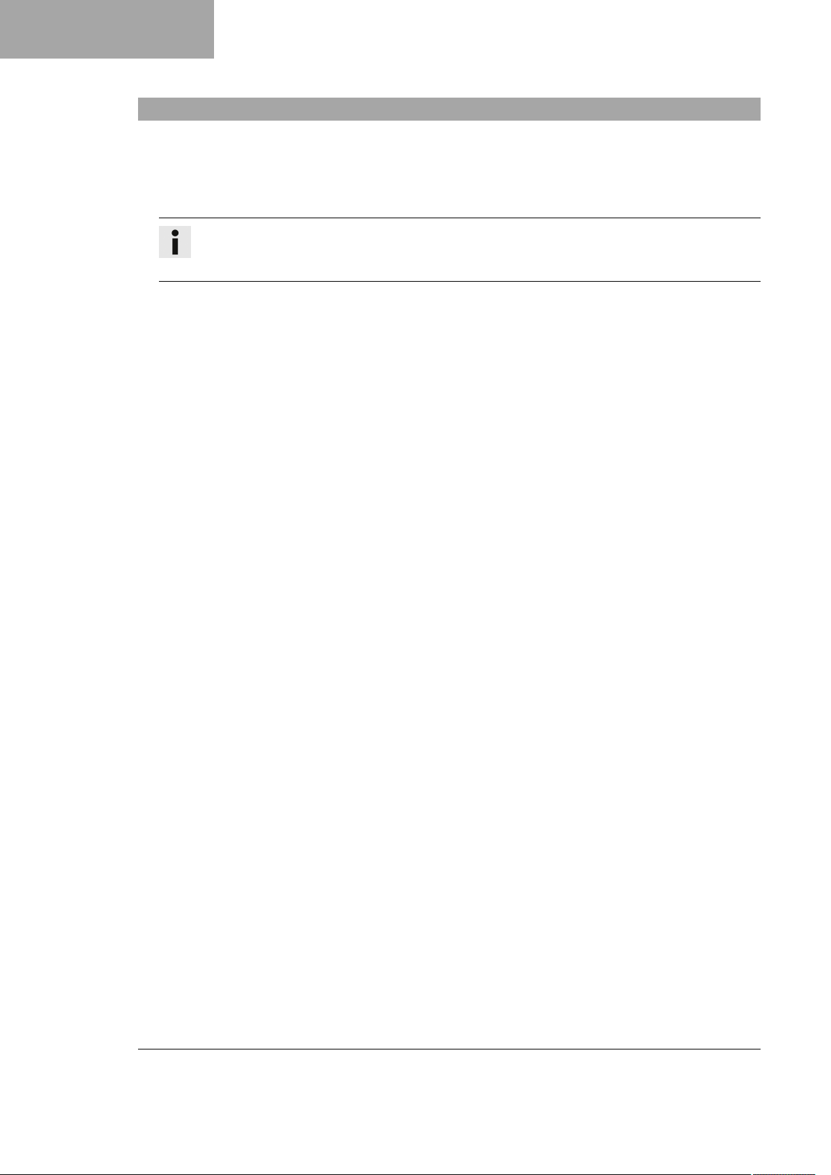
5 SUBSTANCES
Super unleaded (ROZ 95)
Standard/classification
– DIN EN 228 (ROZ 95)
Guideline
– Only use super unleaded fuel that matches or is equivalent to the specified standard.
– Fuel with an ethanol content of up to 10% (E10 fuel) is safe to use.
Info
Do not use fuel containing methanol (e.g., M15, M85, M100) or more than 10% ethanol (e.g., E15,
E25, E85, E100).
24
Page 27
*3214394en*
3214394en
12/2020
KTM Sportmotorcycle GmbH
5230 Mattighofen/Austria
http://www.ktm.com
Photo: Mitterbauer/KISKA/KTM
 Loading...