

Page 1
’04-‘05 KTM 450/525 EXC & MXC
–
DUAL SPORT KIT INSTALLATION MANUAL
1. Get a degree in Mechanical and Electrical Engineering. (kidding)
2. Remove the seat and fuel tank. Unplug and remove the kill button and its
wiring.
3. EXC – Unplug and remove the headlight. MXC – Remove the front
number plate.
4. EXC - Unplug the stock taillight from the bike’s wiring harness (plastic
connector at the front of the airbox) and remove the rear fender/side panel
plastic from the bike. Unbolt and
remove the stock taillight from the rear
fender. MXC – Remove the rear
fender/side panel plastic from the bike.
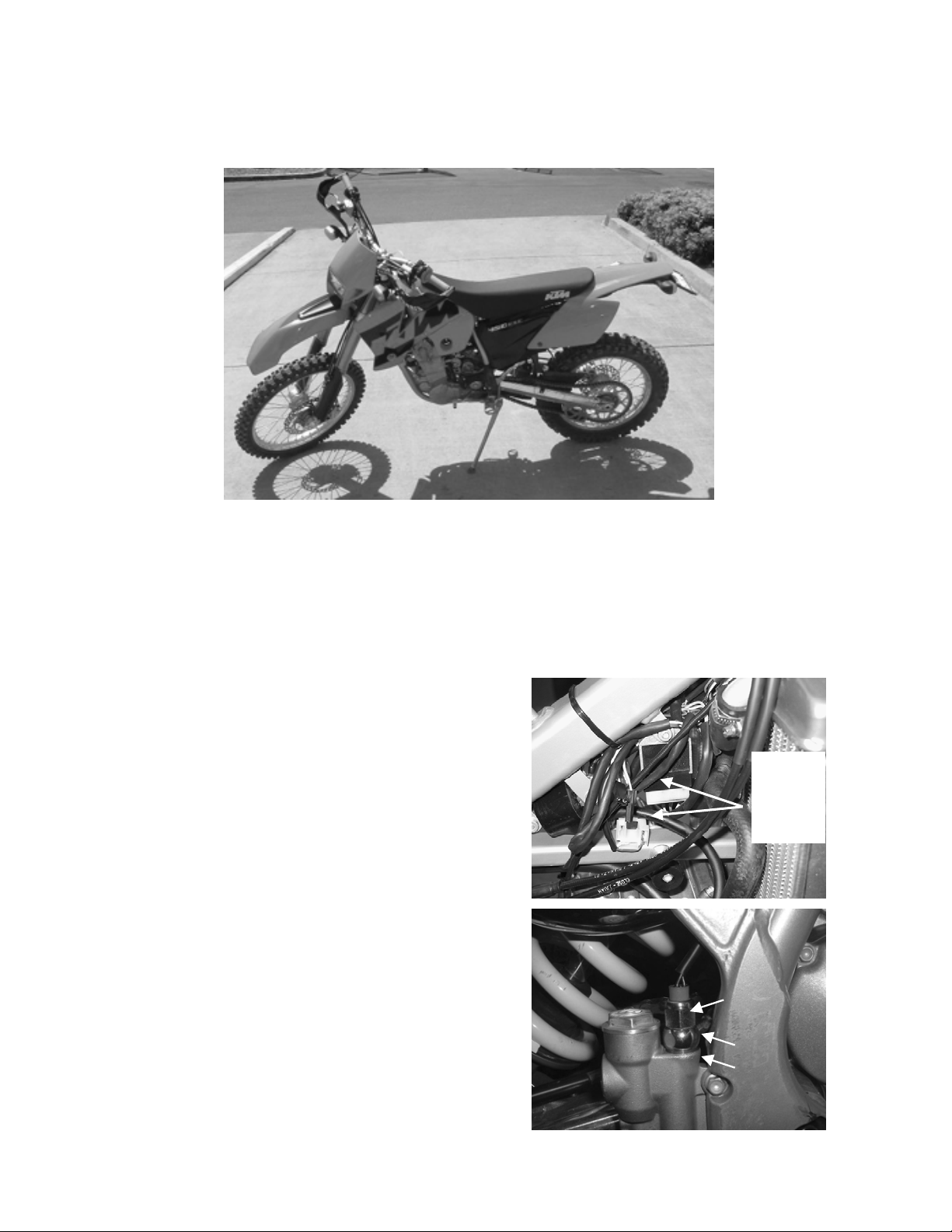
5. MXC Only – Locate the stock lighting
wiring harness zip-tied under the
frame back bone (see Photo 1.)
Remove the securing zip-ties and
route this wiring forward to the area
behind the headlight. Route along the
right side of the frame using the
factory wire guide clamp.
6. Brakelight Switch Installation: The
KTM kit uses a hydraulic brakelight
switch. This requires replacing the
rear master cylinder banjo bolt with a
specially made switch. Installing the
switch requires bleeding the brake. If
you do not feel competent bleeding
your rear brake, please refer this
job to a qualified mechanic, as
Photo 2
Photo 1
brakeswitch
MXC
route this
wiring to
the front
of the
bike
Retain
copper
washers
Page 2
failure to do it correctly will make the brake inoperable.
Remove the stock banjo bolt and replace with the hydraulic switch as
shown. Make sure to install the copper crush washer from the stock
bolt under the switch (Photo 2). Torque to 25 lbs.
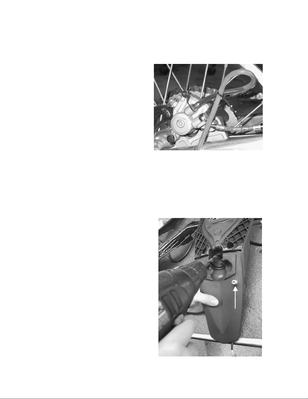
Bleeding the Brake: (do not
begin this process unless
you have a fresh can of brake
fluid.) Remove the lid from the
rear brake reservoir (left side
under carburetor.) Put the box
end of a 11mm wrench over the
caliper bleed nipple and install
the supplied bleed hose tightly
over the nipple. Position the
loop on the hose above the
nipple as shown in Photo 3 with
the other end of the hose in a
container to catch the fluid. Crack the bleed nipple open about 1/8 to a
quarter turn keeping the loop in the hose vertical. Slowly depress the
brake pedal to fill the hose with fluid. Pump slowly until you have brake
fluid extending up into the loop, then you can pump the pedal fairly
aggressively to drive air out of the system. The fluid above the bleed
nipple will prevent air from re-entering the system. Do not let the
reservoir go dry – add fluid as needed. Pump the pedal until there is no
more bubbles then close the nipple with the wrench. Double check the
pedal is firm and the brake works properly.
7. Taillight Prep (EXC & MXC):
Remove the taillight lens to
expose the bulb socket. Pull the
socket out of the way and drill a
13/32” hole in the taillight plastic
as shown in Photo 4. This hole is
to allow the rear turn signal and
license plate illuminator light
wires to pass through the taillight
plastic.
8. License Plate Illuminator Light
Installation: Locate the license
plate illuminator light in the kit
parts bag. It’s a small silver bolt
with two white wires coming out.
Drill a 5/16” hole in the taillight
plastic and mount it in the
location shown in Photo 4. It
should sit directly on top of the
molded ridge in the plastic.
License plate
illuminator light
Photo 4
Photo 3
Page 3
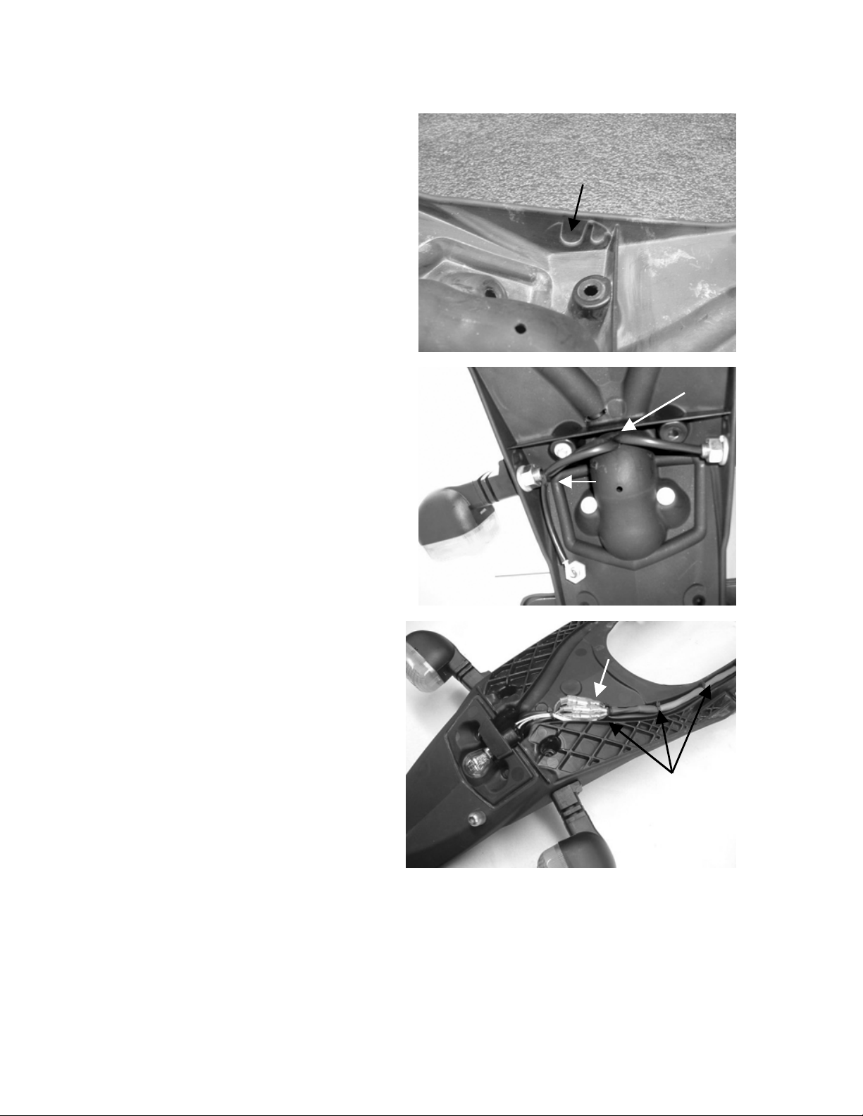
9. Rear Turn Signal
Installation: Looking at the
inside edge of the taillight,
locate the slightly raised
“guides” on each side (see
Photo 5). These are where
the rear turn signals will
mount on the taillight. Mark
the center of these guides
with an awl and drill a 13/32”
hole through the center of
each one. Mount two of the
turn signals to these locations.
10. Rear Turn Signal and
License Plate Illuminator
Wire Routing: Route the rear
turn signal and license plate
illuminator light wires through
the hole in the taillight you
drilled in step 7. (See Photo 6)
Use a zip-tie to secure the
license plate illuminator wires
in place.
11. Rear Wiring Harness
Installation: Locate the
longer of the two gray cables
that came in the dual-sport
kit. It will have a plastic plug
on one end and several
female terminals on the
other. Position the harness
so the female terminals can
connect with the males from
the turn signals and
illuminator light. Once it is
positioned make the
following connections:
Attach one of the two
•
white wires from the
license plate
illuminator (doesn’t matter which) to the black female terminal from
the gray cable.
• • Attach the remaining white wire from the license plate illuminator to
the red wire from the gray cable.
Attach one of the two wires (doesn’t matter which) from the right
turn signal to the green wire from the gray cable.
Photo 5
Photo 6
Drill 13/32” hole here
(rear turn signal
mounting location)
Route wires through hole
Zip-tie
here
Male/female
connections
Rear wiring
harness
Photo 7
Page 4

Attach one of the two wires
•
(doesn’t matter which) from the
left turn signal to the white wire
from the gray cable.
•
Attach the two remaining wires
from the turn signals to the
black double-female connector
from the gray cable.
Once the connections are made, drill
several small holes and zip-tie the
harness into place along the same slot
as the stock taillight wires as shown in
Photo 7. EXC - You may now reinstall
the taillight onto the fender and
reinstall the fender onto the bike.
MXC – Since the MXC fender does
not have the molded bosses to accept
EXC style mounting screws, you must
drill two ¼” holes through the tallight
and fender plastic and use the
provided countersunk hardware to
mount the taillight as shown in Photo
8. Route the wires to the front of the
airbox as shown in Photo 9.
12. Mid Harness Installation: Locate the
remaining gray cable that came in the
dual-sport kit. This will be used to
mate the taillight, brakeswitch, and
rear turn signal wiring to the rest of the
lighting system. One end of this
harness will have a 6-pin plastic
connector with a short extension that
terminates with a 2-pin connector.
Feed this end through the opening
directly above the shock reservoir and
out the right side of the bike next to
the carburetor as shown in Photo 10.
Next, feed the 2 plugs over the back
side of the carb to left side of the bike.
Then, following the stock wiring
harness, route the plugs to the front of
the bike along the left side of the
frame. The 6-pin plug should
terminate at the location shown in
Photo 11. We will attach these plugs
in a later step.
MXC Taillight Mounting
Hardware Locations
Photo 9
Photo 10
Photo 11
Photo 8
Rear harness
and taillight
wire routing
6-pin plug
Position 6-pin
plug here
Page 5

13. Front Turn-Signal
Installation: Mount the
front turn-signal mounting
bracket to the upper tripleclamp as shown in Photo
12. Mount the front turnsignals to this bracket.
EXC’s use the existing
Photo 12
bolts to mount this
bracket. MXC’s use the two
6x12mm bolts found in the parts
bag to mount this bracket.
14. Lens, Flasher, Horn, and Relay
Installation (’04 EXC Only):
Replace the stock plastic 35W
headlight lens with the provided
55/60W glass lens assembly.
Mount the flasher, horn and relay
to the stock headlight as shown
in Photo 13.
15. Switch Panel & Front Wiring
Installation: Install the turn
signal switch on the left
handlebar next to the grip as shown in
Photo 14. The switch has a single
screw that pinches it together on one
side. Two tabs secure the switch halves
on the other side. Remove the screw to
separate the halves so that it can be
installed on the handlebar. When
installing the switch to the handlebar,
make sure the tabs are seated in their
locating holes and then tighten the pinch
screw. DO NOT OVER-TIGHTEN THIS
SCREW! Too much force can strip the
body of the switch. Move the clutch
Photo 13
Flasher
Horn
Relay
Photo 14
perch to the right on the handlebar until
the red adjuster knob cannot contact the
body of the switch assembly when the
clutch is pulled. Run the wires along the
underside of the handlebar and down
over front of the triple-clamp.
16. High-Beam Indicator Installation:
Attach the high-beam indicator bracket
to the stock headlight switch bracket as
shown in Photo 15.
Photo 15
Page 6

17. Kill Wire Extension Installation: Locate the black/white and green two-
wire extension in the dual-sport kit parts bag. It has a ring terminal and
female connector on one end and two females on the other. Secure the
ring-terminal to the ground bolt under the fuel tank (same bolt the stock kill
button was removed from in step 3.) Attach the female connector to the
black/yellow wire from the CDI module (wire the kill button unplugged from
in step 3.) Route the extension to the front of the bike along the left side.
We will plug in the remaining connectors in the next step.
18. Front Wiring Connections: You will now make all the necessary wiring
connections at the front of the bike. Reinstall the headlight once these
connections are made.
If you are colorblind or even think you might be a little color blind, now is the
time to get someone to assist you. Successful installation of the kit requires
good color recognition. You want to go riding this weekend, don’t you?
•
Attach the 6-pin connector from the front wiring harness to its
corresponding mate from the mid-harness you routed in step 12. Be
sure to leave enough slack in this connection so the steering can turn
freely from side to side without yanking on the wiring.
Attach the black/white and green/yellow wire pair from the front wiring
•
harness to the black/white and green wires from the kill-wire extension
you installed in step 17.
Plug the green and black wire pair from the front wiring harness into
•
the two wires from the right turn signal. Plug the brown and black wire
pair from the front wiring harness into the two wires from the left turn
signal.
Plug the gray and purple wire pair into the two horn terminals. Polarity
•
is unimportant.
Locate the red and orange wire pair. Plug the red wire into the
•
terminal marked “P” on the flasher. Plug the orange wire into the
terminal marked “L” on the flasher.
Plug the yellow and black wire pair (both females) from the front
•
harness into the yellow and black male wires from the relay.
EXC Only - Unplug the plastic terminal with the two white wires from
•
the stock headlight on/off switch (leave the yellow wire attached to the
switch). Attach the blue wire from the relay to the switch in its place.
MXC Only – Plug the blue wire from the relay into the stock yellow
•
wire (plastic connector) that you routed to the front of the bike from
under the tank in step 5. The remaining terminals from the stock
wiring harness will be left unplugged.
Attach the black and yellow wire pair (male and female) to the two
•
wires from the high-beam indicator.
Page 7

19. Mid-Harness Connections: You will now make all the necessary wiring
connections under the fuel tank and seat.
Under the fuel tank, locate
•
the unused white 2-wire
connector from the stock
wiring harness (see Photo
14.) It may be bundled up in
the stock wiring. Free this
connector and attach it to
the corresponding 2-wire
connector from the Baja
Designs mid-harness (short
extension from the 6-pin
connector.)
•
At the front of the airbox,
attach the 3-wire connector from the Baja Designs mid-harness to
the corresponding 3-wire connector from the taillight. See Photo
15. The taillight connector from the stock wiring harness will no
longer be used and will remain unplugged for this installation.
•
At the same location on the airbox, attach the 4-wire connector
from the Baja Designs mid-harness to its corresponding mate from
the Baja Designs rear-harness. See Photo 15.
•
Route the yellow and
red wire pair from the
mid-harness down to
the brakeswitch along
the main frame tube.
Attach these two wires
to the two wires from
the brakeswitch.
Polarity is unimportant.
Carefully zip-tie these
wires so they cannot
burn on the exhaust.
Locate this plug and attach it to
its corresponding mate from the
Baja Designs wiring harness
Photo 15
Photo 14
The wiring installation is now completed!
Proceed to the next section to test your work.
Page 8

The switch panel in this kit controls all the lighting functions in one compact
package. Using the lighting selector, push the switch to the second position.
The rear taillight should come on. Test the brake-light. Test the turn signals.
Honk the horn (unless its after 11 PM!).
Kill Button
Because the headlight is
powered directly off the
coil, (not backed up by
the battery) it will not
Fourth Position:High
Beam
turn on until the engine
is running. The low-
Third Position:
Low Beam
beam will be lit in both
the second and third
switch positions when
the engine is running.
EXC - The stock
headlight switch must be
Second Position:
Low Beam
First Position:
Shuts off bike,
turns off lights
in the “on” position for
the headlight to function.
Note: The switch must
now be in one of the
upper three positions
for the bike to start.
Click the main switch
into the “off” position if
using the button to kill
Horn
the engine. If you don’t,
the taillight will remain lit
and discharge the
battery.
Photo 22
Turn Signal
Switch
If every thing is working properly congratulate yourself on a job well done.
Proceed to the “wrapping it up” section. If not, don't worry, it's not rocket science
and we should be able to figure it out. All the components were checked for
operation prior to being shipped to you so something is probably not connected
correctly. See the trouble-shooting list in the next section of this manual.
Wrapping it Up: It is important that all the wires be properly routed and secured.
Double-check the photos and sketches with regards to wire routing. Make sure
the wires do not pass over any sharp edges, are pulled overly tight, or can be
crushed by the seat, tank, fender, etc. Use all the zip ties provided to securely
fasten the wires. Any unwanted movement or chafing means early failure when
Page 9

off the road. Make sure all the silicone rubber connector boots and the
connectors are pushed firmly together and no bare metal is exposed.
TROUBLESHOOTING
Nothing happens when you turn the power switch on:
•
Fuse is blown. Check for bare wire or terminal shorting against the
frame or another wire.
•
6-pin connector not properly connected.
•
2-wire connector under fuel tank is not properly attached to its mate
from the Baja Designs wiring harness.
•
Battery is dead. Measure voltage with voltmeter, or connect a 12volt light across it. A fully charged battery should measure around
13.2 volts.
The turn signals won't come on, or won't flash:
The wires on the flasher are connected backward. The red wire
•
goes to the terminal labeled "P", orange goes to “L”.
Check turn signal wire connections.
•
Make sure you have connected the correct wires to the turn signals.
•
Check instructions.
Headlight won’t come on:
The stock headlight switch must be in the “on” position and the
•
engine must be running for the headlight to function.
The blue wire from the relay is not properly connected to the stock
•
headlight switch.
The H4 headlight connector from the relay is not properly attached
•
to the three prongs from the back of the bulb.
If you still need assistance, call Baja Designs at (760)560-2252.
Maintenance: Occasionally examine the wires in your lighting system to make
sure they are not chaffing or binding so that they don't cause you a problem
when you're out on the trail or on the road. A well-routed, properly secured
wiring system is key to getting long life and trouble free performance from your
conversion kit. The light bulbs take a beating on a dirt bike, especially the rear
taillight’s. The continuous vibration and impact can cause the bulb contact to
prematurely oxidize, causing the bulb to fail. Occasionally remove the bulbs
(taillight and turnsignals) and scrape the soft contact at the base of the bulb and
clean its mating contact in the lamp assembly.
Page 10

Baja Designs
185 Bosstick Blvd.
San Marcos, California 92069
760.560.2252
www.bajadesigns.com
 Loading...