

Page 1
REPAIR MANUAL
REPARATURANLEITUNG
MANUALE DI RIPARAZIONE
MANUEL DE RÉPARATION
MANUAL DE REPARACIÓN
ART.NR.: 3.206.006-E
KTM Group Partner
400-660LC42003
Page 2

Page 3
400-660LC4
REPAIR
MANUAL
Page 4

Page 5

1 SERVICE-INFORMATIONS
2 GENERAL INFORMATION
3 REMOVING AND REFITTING ENGINE
4 DISASSEMBLING THE ENGINE
5
SERVICING ON INDIVIDUAL COMPONENTS
6 ASSEMBLING THE ENGINE
7 ELECTRICAL
8 FUEL SYSTEM
9 TROUBLE SHOOTING
10 TECHNICAL SPECIFICATIONS
11 PERIODIC MAINTENANCE SCHEDULE
12 WIRING DIAGRAMS
13
14
15
16
Page 6

Page 7
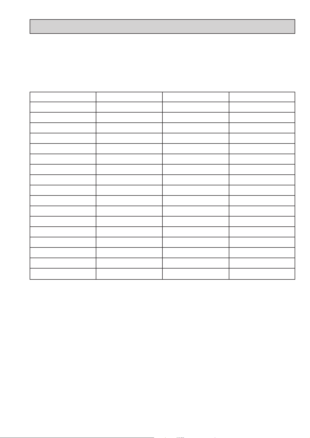
Remove page (s) Replace by page (s) Insert page (s) after page
2-1C to 2-3C 2-1D to 2-3D 2-5D
2-5C to 2-11C 2-6D to 2-13D
3-3 3-3D
4-1A 4-1D
4-5 to 4-16 4-5D to 4-17D
5-1A to 5-2A 5-1D to 5-2D
5-12 5-12D
5-14B to 5-17 5-14D to 5-17D
5-21 / 5-25 5-21D / 5-25D
6-1A to 6-2 6-1D to 6-2D
6-5C to 6-19C 6-5D to 6-21D
7-1 to 7-49C 7-1D to 7-51D
8-1C to 8-37C 8-1D to 8-49D
9-1 9-1D
10-1.1C 10-2D 10-62D to 10-72D
11-1C 11-1D 11-22D to 11-27D
12-2C 12-2D 12-57D to 12-66D
IMPORTANT INFORMATION/UPDATING INSTRUCTIONS
To be able to continue using the existing loose-leaf repair instructions, simply print the
following pages and insert them in the existing repair instructions:
15-18, 20-28, 32, 35, 40-54, 64, 66-69, 73, 77, 79-81, 84-207, 219, 280-291,
314-319, 323, 378-387
KTM REPAIR MANUAL IN LOOSE-LEAF FORM
STORING THE REPAIR MANUAL IN THE BINDER
– Put the index into the binder.
– Put the front page of the repair manual (210x297 mm) into the transparent pocket provided
for this purpose on the outside of the binder.
– Put the spine label (170x45 mm) into the transparent pocket provided for this purpose on the
spine of the binder.
– Put the summary list of contents (150x297 mm) into the transparent pocket provided for this
purpose on the inside of the binder or insert this page on the beginning of the manual.
– Then insert the individual chapters of the manual between the sheets of the index according to
the page number printed in the right bottom corner of each page.
Example: page no. 3-5 3 = chapter 3 5 = page 5
All pages with a page number that begins with the digit 3, for example, must be put under the
index heading „Chapter 3“.
– Index sheets that have not been marked with a certain chapter are for your personal convenience.
T
he respective headings can be entered in the list of contents.
Page 8

Page 9

Repair manual KTM LC4 Art.-Nr. 3.206.006 -E
EXPLANATION - UPDATING
Edition 4/2003
3.205.49-E Repair Manual LC4 6/1998
Basicversion Modelyear 1998
(Engine number with first digit „8“)
3.205.73-E Updating of Rep.Manual LC4 7/1999
Modelyear 1999
(Engine number with first digit „9“)
3.205.89-E Updating of Rep.Manual LC4 9/2000
Modelyear 2000/2001
(Engine number with first digit „0“ and „1“)
3.210.30-E Updating of Rep.Manual LC4 12/2001
Modelljahr 2002
(Engine number with first digit „2“)
3.206.006-E Updating of Rep.Manual LC4 4/2003
Modelljahr 2003
(Engine number with first digit „3“)
Modification / Updating:
Special tools, hydraulic clutch, Keihin carburator,
technical details model 2003, technical specification,
Maintenance schedule and wiring diagrams for modell 2003
Page 10

Page 11

INTRODUCTION
This repair manual offers extensiv repair-instructions and is an up-to-date version that describes the
latest models of the series. However, the right to modifications in the interest of technical
improvement is reserved without updating the current issue of this manual.
A description of general working modes common in work shops has not been included. Safety rules
common in the work shop have also not been listed. We take it for granted that the repairs are
made by qualified profesionally trained mechanics.
Read through the repair manual before beginning with the repair work.
WARNING
STRICT COMPLIANCE WITH THESE INSTRUCTIONS IS
ESSENTIAL TO AVOID DANGER TO LIFE AND LIMB.
!
CAUTION
!
NON-COMPLIANCE WITH THESE INSTRUCTIONS CAN LEAD
TO DAMAGE OF MOTORCYCLE COMPONENTS OR RENDER
MOTORCYCLES UNFIT FOR TRAFFIC !
„NOTE” POINTS OUT USEFUL TIPS.
Use only ORIGINAL KTM SPARE PARTS when replacing parts.
The KTM high performance engine is only able to meet user expectations if the maintenance work
is performed regularly and professionally.
KTM Austria’s certificate of achievement for its quality system ISO 9001 is the beginning of an
ongoing total reengineered quality plan for a brighter tomorrow.
KTM Sportmotorcycle AG
5230 Mattighofen, Austria
All design and assembly modification rights reserved.
C
by KTM SPORTMOTORCYCLE AG, AUSTRIA All rights reserved
Page 12

Page 13
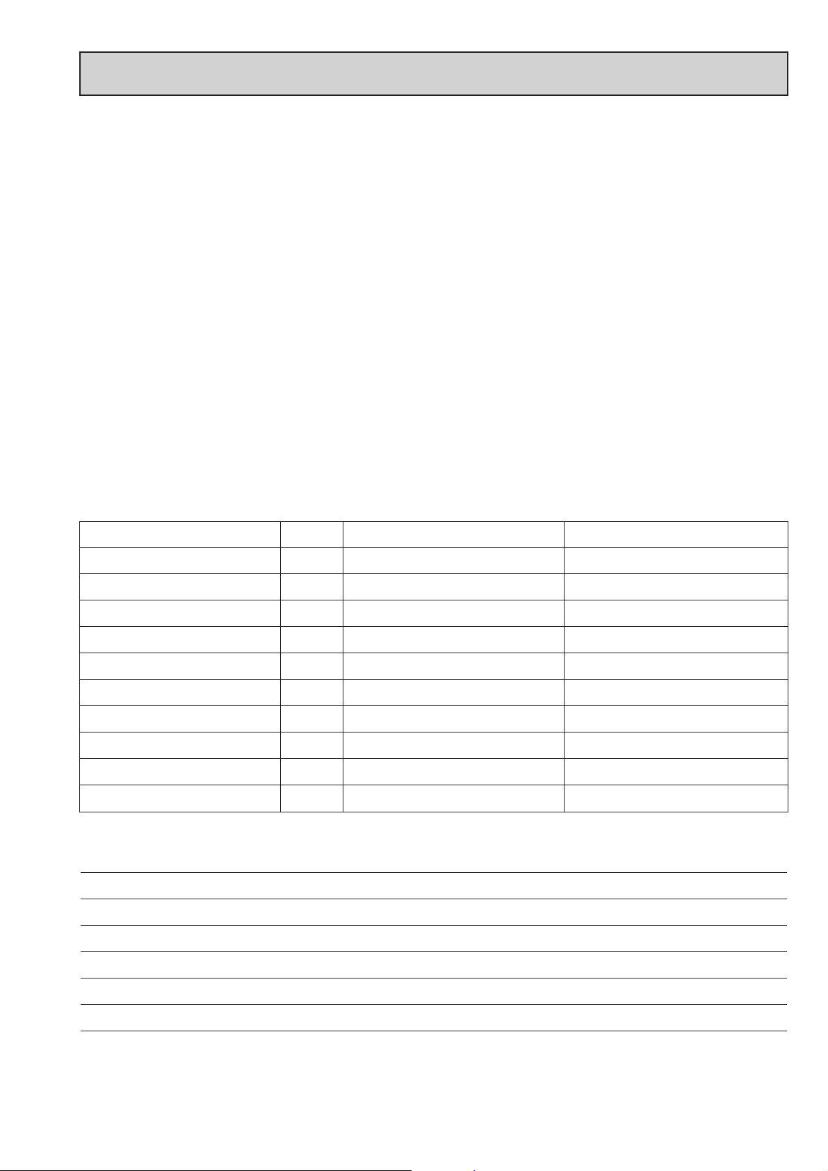
REPLY FAX FOR REPAIR MANUALS
We have made every effort to make our repair manuals as accurate as possible but it is always possible for
a mistake or two to creep in.
To keep improving the quality of our repair manuals, we request mechanics and shop foremen to assist us
as follows:
If you find any errors or inaccuracies in one of our repair manual – whether these are technical errors,
incorrect or unclear repair procedures, tool problems, missing technical data or torques, inaccurate or
incorrect translations or wording, etc. – please enter the error(s) in the table below and fax the completed
form to us at 0043/7742/6000/5349.
NOTE to table:
– Enter the complete item no. for the repair manual in column 1 (e.g.: 3.210.66-E).
You will find the number on the cover page or in the left margin on each right page of the manual.
– Enter the corresponding page number in the repair manual (e.g.: 5-7c) in column 2.
– Enter the current text (inaccurate or incomplete) in column 3 by quoting or describing the respective
passage of the text. If your text deviates from the text contained in the repair manual, please write
your text in German or English if possible.
– Enter the correct text in column 4.
Your corrections will be reviewed and incorporated in the next issue of our repair manual.
Item no. of repair manual Page Current text Correct text
Additional suggestions, requests or comments on our Repair Manuals (in German or English):
Name mechanic/shop foreman Company/work shop
Page 14

Page 15

MODELS WITHOUT FRAME OIL
CHANGING THE ENGINE OIL . . . . . . . . . . . . . . . . . . . . . . . . . . . . . . . . . .2-2
CHANGING THE OIL FILTER . . . . . . . . . . . . . . . . . . . . . . . . . . . . . . . . . . .2-2
CHANGING THE MICROFILTER . . . . . . . . . . . . . . . . . . . . . . . . . . . . . . . .2-3
OIL CIRCUIT . . . . . . . . . . . . . . . . . . . . . . . . . . . . . . . . . . . . . . . . . . . . . .2-4
OIL CIRCUIT 660 SMC . . . . . . . . . . . . . . . . . . . . . . . . . . . . . . . . . . . . . . .2-5
MODELS WITH FRAME OIL
CHANGING THE ENGINE OIL . . . . . . . . . . . . . . . . . . . . . . . . . . . . . . . . . .2-6
CHANGING THE FINE SCREEN FILTER . . . . . . . . . . . . . . . . . . . . . . . . . . . .2-6
CHANGING THE OIL FILTER . . . . . . . . . . . . . . . . . . . . . . . . . . . . . . . . . . .2-7
OIL CIRCUIT . . . . . . . . . . . . . . . . . . . . . . . . . . . . . . . . . . . . . . . . . . . . . .2-8
SECONDARY AIR SYSTEM . . . . . . . . . . . . . . . . . . . . . . . . . . . . . . . . . . . .2-9
EPC-SYSTEM . . . . . . . . . . . . . . . . . . . . . . . . . . . . . . . . . . . . . . . . . . . . .2-10
SPECIAL TOOLS . . . . . . . . . . . . . . . . . . . . . . . . . . . . . . . . . . . . . . . . . . .2-11
BLEEDING OF THE HYDRAULIC CLUTCH . . . . . . . . . . . . . . . . . . . . . . . .2-13
Repair manual KTM LC4 Art.-Nr. 3.206.006 -E
GENERAL INFORMATION
INDEX
2-1D
2
Page 16

Page 17
Repair manual KTM LC4 Art.-Nr. 3.206.006 -E
2-2D
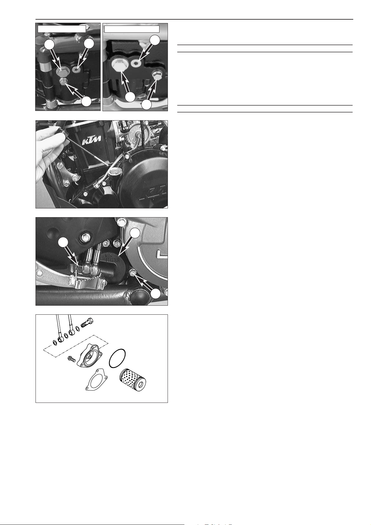
Changing the engine oil (models without frame oil)
NOTE: The engine oil change is to be carried out when the engine is
still warm.
WARNING
A
N ENGINE HAVING BEEN RUN WARM, AND THE ENGINE OIL IN IT ARE VERY HOT -
DO NOT BURN YOURSELF
.
– Place the motorbike on a horizontal surface. Remove the two plugs
(
1 and 2), and drain oil into a container.
NOTE: A third plug was installed in the 660 SMC model. Tightening
torque: 20 Nm
!
CAUTION
!
THE SCREW PLUG A MUST NOT BE REMOVED
, THIS IS PART OF THE BY
-PASS VALVE.
– Clean the plugs thoroughly with a fireproof solvent and compressed
air, in order to remove the metal abrasion.
– After all the oil has drained through, clean raised and flat faces and
install plugs with seals. Tighten plug
1 with 30 Nm (22 ft.lb) and
plug
2 with 20 Nm (15ft.lb).
– Remove the oil dipstick at the clutch cover, pour in engine oil and
replace the oil dipstick.
Oil capacity (up to model 2002) : 1.40 l
Oil capacity (from model 2003 on) : 1.50 l
Changing the oil filter
Replace the oil filter when changing the engine oil.
–Press the foot brake pedal and place a screwdriver or similar between
foot brake pedal and stopper roll so that the oil filter cover is more
accessible.
– Remove banjo bolt
3 and the three bolts 4.
– Remove oil filter cover
5 and oil filter.
– Clean filter housing, oil filter cover and sealing surfaces. Check oil
duct in oil filter cover if clogged.
–Press the new O-ring
6 into the groove of the filter cover (if
necessary fix with grease). Mount a new oil filter
7 on the
connection piece of the oil filter cover an mount the whole unit.
NOTE: From model 2001 onwards the gasket
8 is mounted with a
changed filter cover
5. If the new gasket 8 should be used on older
engines, the filter cover must be flat regrinded or renewed (see
Technical Info Nr. 0201/30/01).
– Mount three bolts and tighten with 5 Nm (4 ft.lb).
– Mount hollow bolt with seal rings and tighten with 15 Nm
(11 ft.lb).
1
1
A
A
2
up to Modell 2001
from Modell 2002 on
2
3
4
5
6
7
8
3
4
5
Page 18
2-3D
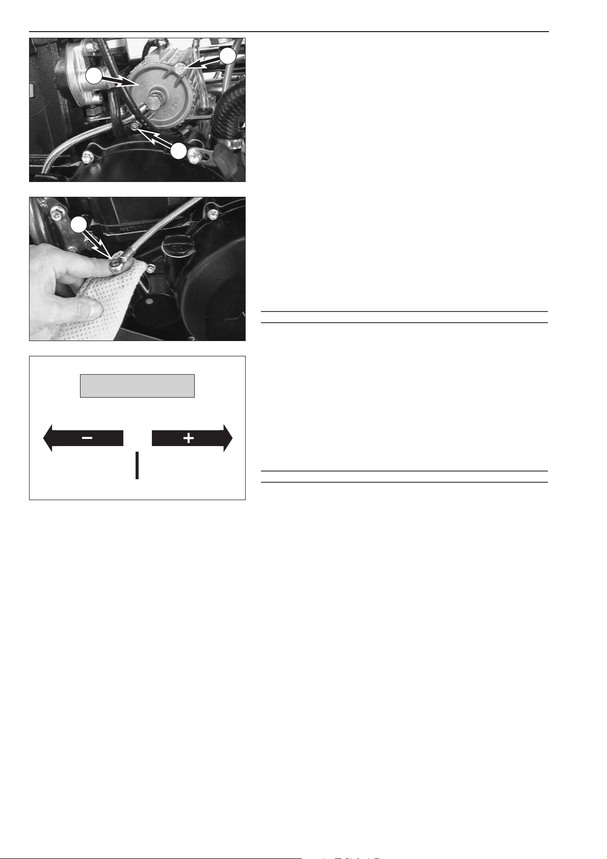
Changing the microfilter
Replace the microfilter while changing the engine oil.
–To do so, remove bolts
1 and take off the microfilter cover 2.
– Remove the microfilter, clean its parts and check the O-ring on the
microfilter cover for signs of damage.
– Insert a new microfilter into the filter housing, tilt the motorcycle
sideways and fill the microfilter housing with engine oil.
– Slightly grease the O-ring and mount the microfilter cover. Then put
the motorcycle back on its stand.
– It is necessary to bleed the microfilter so that all lubricating points
can be quickly supplied with engine oil.
–To do this, fill with oil and remove the jet screw from the oil line on
the clutch cover.
– Start the engine and close off the bore on the clutch cover with a
rag.
– Allow the engine to run at idle until oil runs out of the oil line
3.
–Turn off the engine. Mount the jet screw, using two new seal rings.
–Torque the jet screw to 10 Nm and check for leaks.
– Start the engine and let it idle for 1 - 2 minutes.
!
CAUTION
!
DO NOT REV UP THE ENGINE IMMEDIATELY AFTER AN OIL CHANGE ! KEEP IN MIND
THAT IT TAKES SOME TIME UNTIL ALL LUBRICATING POINTS ARE PROPERLY PROVIDED
WITH ENGINE OIL
.
– Allow the engine to run until warm. Then, turn off the engine, and
place the motorbike on a flat, level surface in an upright position
(center stand). Wait for 5 minutes. Unscrew and remove the oil
dipstick, and wipe it clean with a cloth.
– Screw the dipstick in all the way and remove it again. The oil level
should be between the two marks on the oil dipstick, however, it
must never rise above the MAX mark. Otherwise, engine oil would
get into the air filter box by way of the engine venting system. Add
engine oil, if necessary.
–Finally, check oil system and engine for leaks.
!
CAUTION
!
–ONLY USE HIGH
-QUALITY OILS MEETING OR SURPASSING THE QUALITY
REQUIREMENTS OF
JASO T903 MA (FOR SPECIFICATIONS SEE CONTAINERS).
–I
NSUFFICIENT OIL OR POOR QUALITY OIL RESULTS IN PREMATURE WEAR OF THE
ENGINE
.
–Y
OU MAY USE EITHER MINERAL OILS OR SYNTHETIC OILS FULFILLING THE ABOVE
CRITERIA
.
NOTE: Dispose of used oil properly !
Under no circumstances may used oil be disposed of in the sewage
system or in the open countryside.
1 liter oil contaminates 1.000.000 liter water.
3
1
1
2
0°C
32°F
10W/50
5W/40
JASO T903 MA
TEMPERATURE
Page 19
2-4D
Repair manual KTM LC4 Art.-Nr. 3.206.006 -E
Page 20
2-5D
Page 21
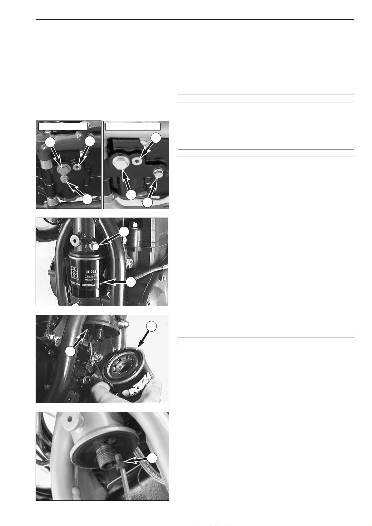
2-6D
Repair manual KTM LC4 Art.-Nr. 3.206.006 -E
Changing the engine oil (models with frame oil)
NOTE: For improved cooling of the engine oil, the front tube of the
frame was integrated into the oil circuit.Thus, when you change the oil,
you also have to drain the engine oil from the front tube and bleed the
oil system.
If the oil system is not bled at all or bled insufficiently, the bearings of
the engine will not get enough lubrication, which in turn may result in
engine failure.
The engine oil change is to be carried out when the engine is still warm.
WARNING
AN ENGINE HAVING BEEN RUN WARM, AND THE ENGINE OIL IN IT ARE VERY HOT -
DO NOT BURN YOURSELF
.
– Place the motorcycle on a horizontal surface. When working on a
motorcycle with engine guard, remove the latter before commencing
to change the engine oil.
– Remove the two plugs
1 and 2, and drain oil into a container.
!
CAUTION
!
PLUG A MUST NOT BE REMOVED,
THIS IS PART OF THE BY
-PASS VALVE
.
Changing the fine screen filter
Replace the fine screen 3 filter when changing the engine oil.
– Loosen the three bolts and remove the cover.
– Undo the spin-on filter
3 with the corresponding special tool, twist
it off manually and let the engine oil out of the front pipe of the
frame.
– Unscrew plug
4 at the lower end of the front pipe and drain oil (up
to model 2000).
– Clean sealing surfaces on the front pipe
5, fill new fine screen filter
with engine oil, and oil rubber gasket
6. Replace fine screen filter
and screw it back in place, your bare hand will do.
!
CAUTION
!
USE ONLY ORIGINAL KTM FINE SCREEN FILTERS. USING ANOTHER FILTER BRAND CAN
RESULT IN DAMAGE TO THE ENGINE
!
–From model 2001 onwards the drain plug 7 of the frame oil is
located in the oil filter flange, draining is only possible after removing
the oil filter.
– Clean all 3 plugs thoroughly with a fireproof solvent and compressed
air, in order to remove the metal abrasion.
– After all the oil has drained through, clean sealing areas and install
plugs with gaskets. Tighten plug
1 with 30 Nm (23 ft.lb), plug 2
with 20 Nm and plug 4 with 10 Nm (up to model 2000). Drain plug
of frame oil (model 2001 onwards) is to be mounted without a
gasket and tightened to 10 Nm (7 lb.ft).
1
1
A
A
2
up to Modell 2001
from Modell 2002 on
2
5
3
4
6
7
Page 22
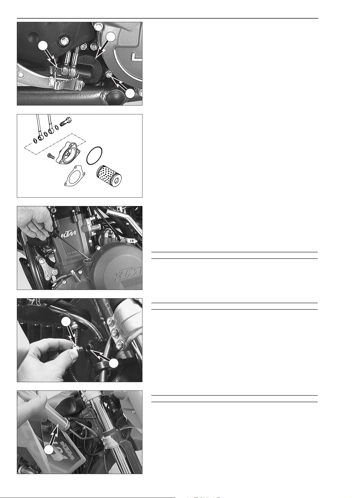
2-7D
Changing the oil filter
Replace the oil filter when changing the engine oil.
–Press the foot brake pedal and place a screwdriver or similar between
foot brake pedal and stopper roll so that the oil filter cover is more
accessible.
– Remove banjo bolt
1 and the three bolts 2.
– Remove oil filter cover
3 and oil filter.
– Clean filter housing, oil filter cover and sealing surfaces. Check oil
duct in oil filter cover if clogged.
–Press the new O-ring
4 into the groove of the filter cover (if
necessary fix with grease). Mount a new oil filter
5 on the
connection piece of the oil filter cover an mount the whole unit.
NOTE: From model 2001 onwards the gasket
6 is mounted with a
changed filter cover
3. If the new gasket 6 should be used on older
engines, the filter cover must be flat regrinded or renewed (see
Technical Info Nr. 0201/30/01).
– Mount three bolts and tighten with 5 Nm (4 ft.lb).
– Mount banjo bolt with seal rings and tighten with 15 Nm
(11 ft.lb).
– Remove the oil dipstick at the clutch cover, pour in engine oil and
replace the oil dipstick.
Oil quantity (engine only) : 1.40 liter
!
CAUTION
!
IF THE ENGINE OIL HAS BEEN DRAINED FROM THE FRONT PIPE OF THE FRAME
, YOU
MUST BLEED THE OIL SYSTEM
!
– Remove the plug
7 next to the steering head and use a lubricating
syringe
8 (see special tools) to fill the front pipe with approx. 0.6 l
engine oil. Add oil until it begins to emerge at bore
B.
– Mount the plug, using a new seal ring.
!
CAUTION
!
DO NOT REV UP THE ENGINE IMMEDIATELY AFTER AN OIL CHANGE. KEEP IN MIND
THAT IT TAKES SOME TIME UNTIL ALL LUBRICATING POINTS ARE PROPERLY PROVIDED
WITH ENGINE OIL
.
– Allow the engine to run until warm. Then, turn off the engine, and
place the motorbike on a flat, level surface in an upright position
(center stand). Wait for 5 minutes. Unscrew and remove the oil
dipstick, and wipe it clean with a cloth.
– Screw the dipstick in all the way and remove it again. The oil level
should be between the two marks on the oil dipstick, however, it
must never rise above the MAX mark. Otherwise, engine oil would
get into the air filter box by way of the engine venting system. Add
engine oil, if necessary.
–Finally, check oil system and engine for leaks.
!
CAUTION
!
–ONLY USE HIGH-QUALITY OILS MEETING OR SURPASSING THE QUALITY
REQUIREMENTS OF
JASO T903 MA (FOR SPECIFICATIONS SEE CONTAINERS).
–I
NSUFFICIENT OIL OR POOR QUALITY OIL RESULTS IN PREMATURE WEAR OF THE
ENGINE
.
–Y
OU MAY USE EITHER MINERAL OILS OR SYNTHETIC OILS FULFILLING THE ABOVE
CRITERIA
.
NOTE: Dispose of used oil properly !
Under no circumstances may used oil be disposed of in the sewage
system or in the open countryside !
1 liter oil contaminates 1.000.000 liter water !
B
1
2
3
4
5
6
3
1
2
7
8
Page 23
2-8D
Repair manual KTM LC4 Art.-Nr. 3.206.006 -E
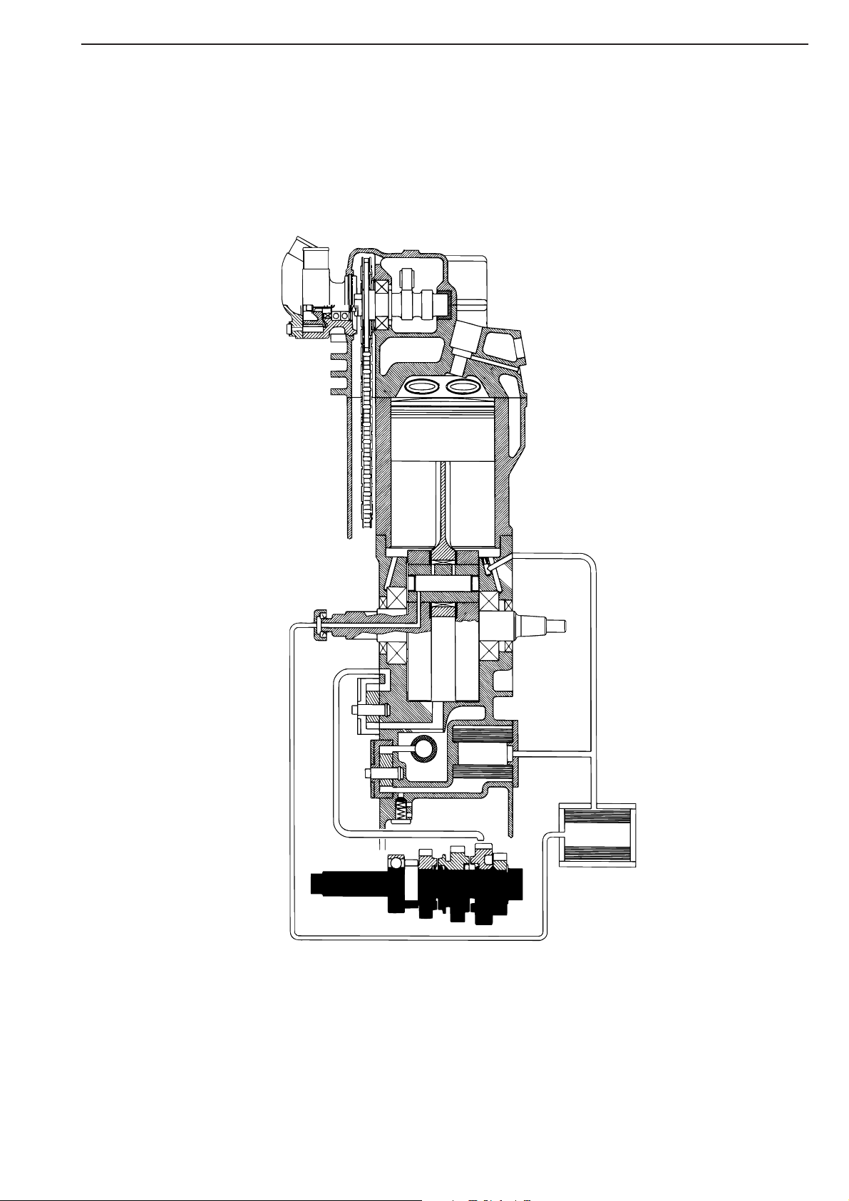
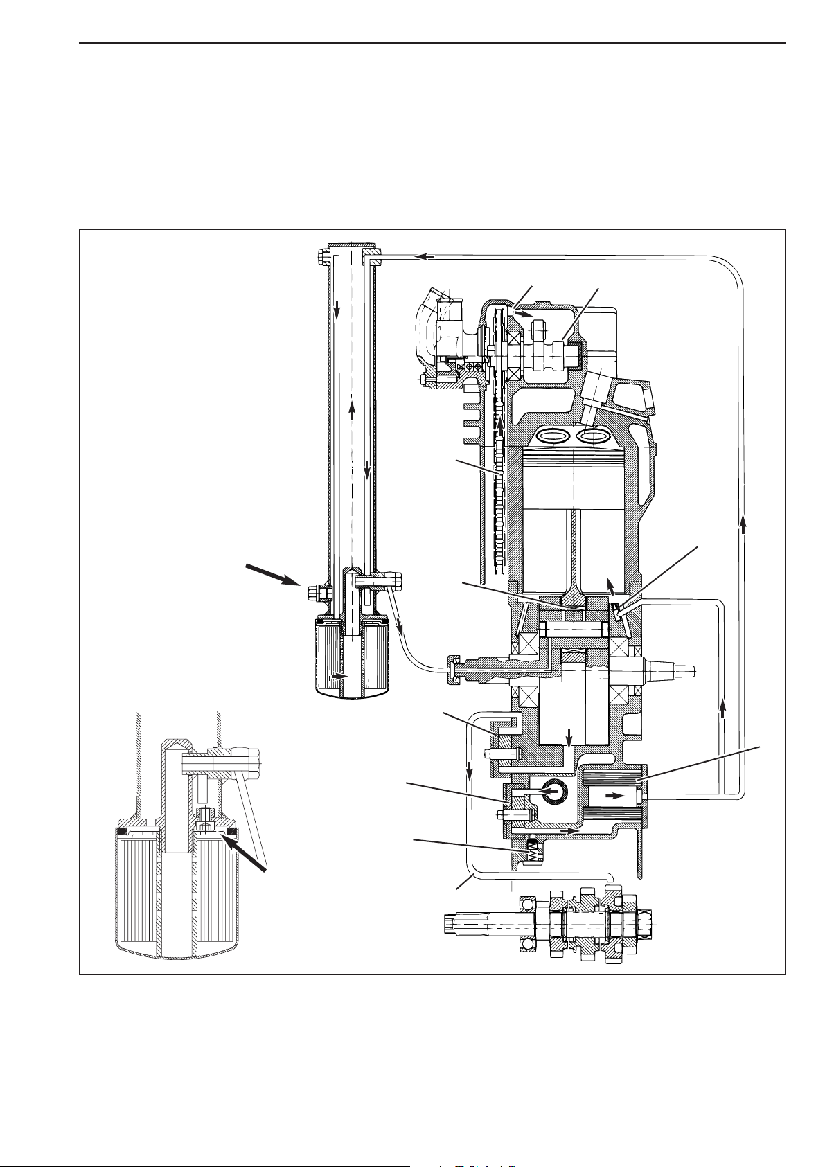
Oil circuit
The oil pump 1 pumps the engine oil past the by-pass valve 2 through the oil filter 3. After the oil filter, an oil line branches off
to a jet
4 which sprays engine oil onto the piston pin bearing and piston head. The second oil line takes the main flow of oil into
the front pipe of the frame
5, where the engine oil is cooled down. Afterwards the engine oil runs through the fine screen filter
6, which filters out even the finest impurities. The cleaned engine oil is pumped through the oil line and the clutch cover into the
crankshaft to the conrod bearing
7 and drips into the crankcase. An additional oil pump 8 sucks the engine oil out of the
crankcase and pumps it through the oil line
9 to the gear wheels of the 4th and 5th gear. Via the gear wheels, the engine oil
reaches the oil sump. The timing chain
bk runs through the oil sump and transports the engine oil upwards to the cylinder head.
Through the bore hole
bl the oil reaches the camshaft bm and the valves.
8
7
5
6
9
10
12
11
1
2
3
4
Drain plug - frame oil
up to Model 2000
Drain plug - frame oil
Model 2001 onwards
Page 24
2-9D
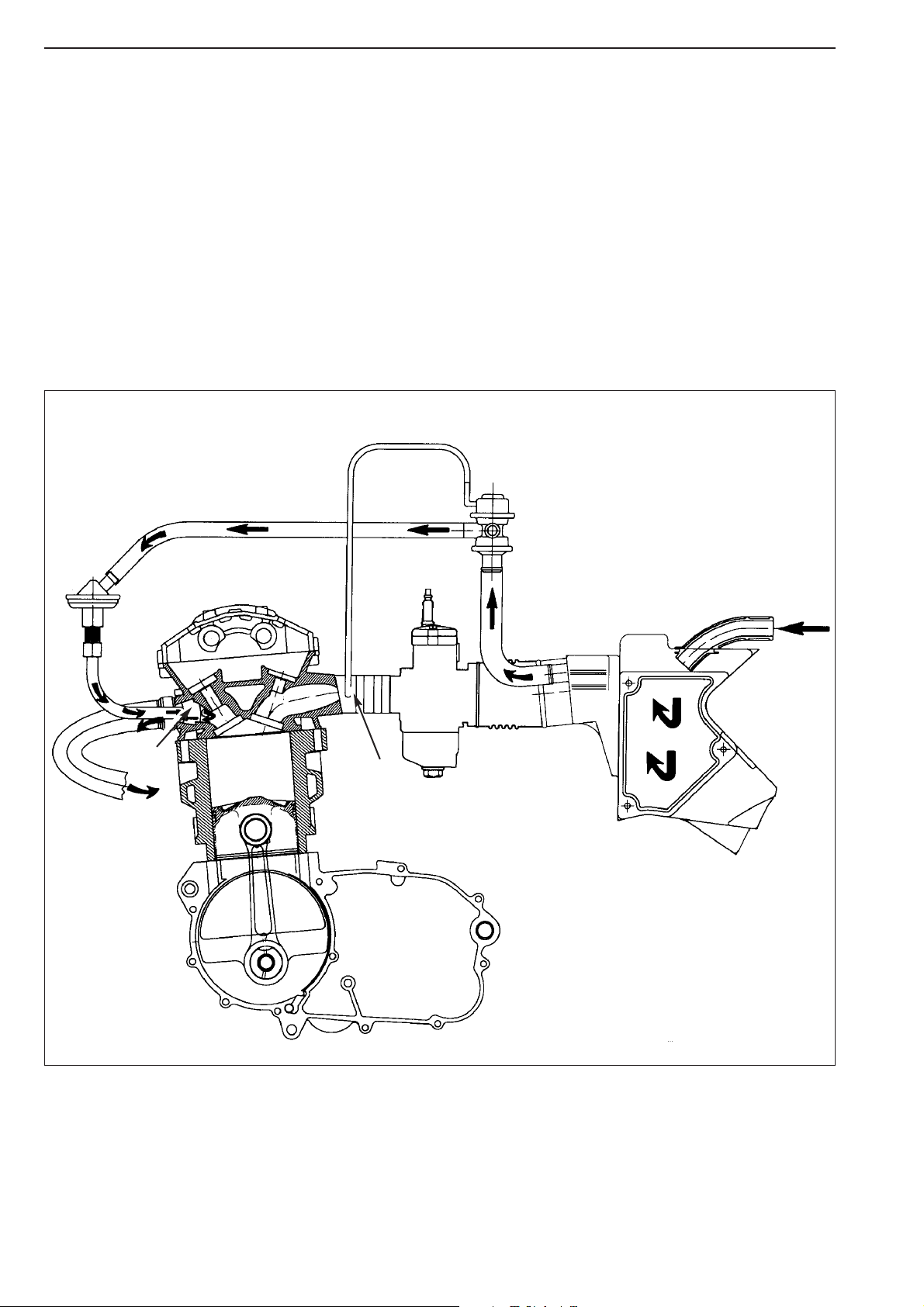
Functional characteristics of the secondary air system (SLS)
When the exhaust valve is open, the hot exhaust gases flow through the exhaust port 1 at a very high speed. As a consequence
of the flow conditions in the exhaust port and due to the influence exerted by the entire exhaust system on the escaping gases,
the pressure in the exhaust port drops temporarily (underpressure).
During these cyclic underpressure phases, the secondary air valve
2 opens, thus adding oxygen of the air to the hot exhaust
gases through pipe
3.
At higher engine speeds, the secondary air valve interrupts the oxygen supply to prevent overheating of the catalytic converter.
Additionally, the secondary air valve prevents the exhaust gases from flowing back into the air filter box
4.
When the motorcycle is pushed (high underpressure in the intake port) the control valve (ASV)
5 interrupts the air flow into the
exhaust port to prevent exhaust detonations.
The control valve is controlled via a control pipe
6. This control pipe transmits the underpressure from the intake port 7 to the
control valve.
During normal operation (slight underpressure in the intake port), the control valve is open.
The reaction between the oxygen of the air and the harmful components of the exhaust gases (CO - carbon monoxide, HC hydrocarbon) reduces the content of harmful substances by approximately 50%. The use of a catalytic converter, in combination
with the SLS, allows an additional significant reduction of pollutant emissions.
6
5
7
3
2
1
4
Page 25
Repair manual KTM LC4 Art.-Nr. 3.206.006 -E
2-10D
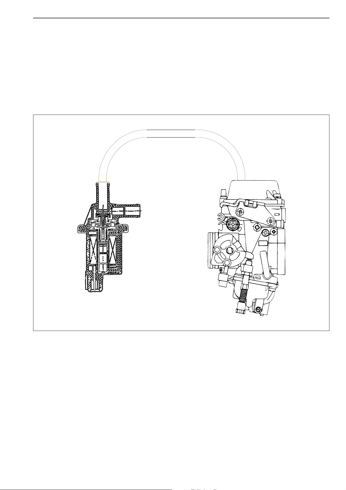
Electronic Power Control System (EPC)
Main components of the EPC system:
– Constant-pressure carburetor
– Control device
– Solenoid valve
– 2 contact screws at the engine
– Micro-switch (at carburetor)
FUNCTIONAL CHARACTERISTICS:
The EPC system is not activated during normal operation of the motorcycle.
It is, however, activated as soon as the throttle is fully opened at a speed of 45 - 55 km/h while the second or third gear are
engaged.
The EPC control device opens the solenoid valve, directing an appropriate flow of fresh air onto the upper side of the slide
membrane of the constant-pressure carburetor, thus reducing the opening speed of the slide. This mechanism significantly reduces
the exhaust gas emissions of the vehicle.
SOLENOID VALVE
Page 26
2-11D
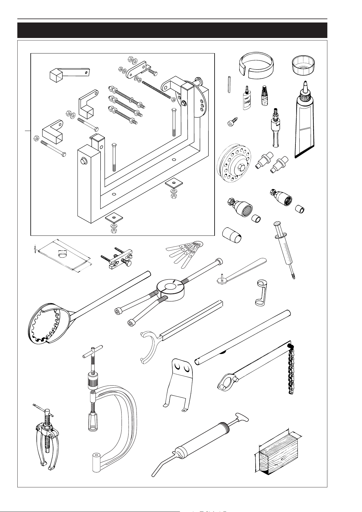
SPECIAL TOOLS
6
39
26
11
648
12
20
16
1
ThreeBond
1215
18
Silicone Liquid Gasket
Silicone Flüssige Dichtung
23
4#
4
5#
5
5
27
150
7
10
3
49
14
70
15
19
9
2
17
8
22
8#
130
35
48
65
Page 27

Repair manual KTM LC4 Art.-Nr. 3.206.006 -E
2-12D
FIG. PART NO. DESCRIPTION
1 560.12.001.000 Universal engine work stand
2 583.29.003.000 Clutch holder
3 580.12.005.025 Mounting sleeve for crankshaft seal ring Ø 25 mm
4 584.29.009.000 Magneto extractor (Kokusan)
4# 580.12.009.000 Magneto extractor (SEM)
5 510.12.016.000 Protection cover for crankshaft (SEM)
5# 584.29.031.000 Protection cover for crankshaft (Kokusan)
6 580.12.015.089 Piston ringspanner Ø 89 mm
580.12.015.095 Piston ringspanner Ø 95 mm
580.12.015.100 Piston ringspanner Ø 100 mm
580.12.015.101 Piston ringspanner Ø 101 mm
585.29.015.102 Piston ringspanner Ø 102 mm
7 590.29.021.044 Extractor for primary gear and clutch hub
8 580.12.019.000 Valve mounting set
8# 590.29.019.000 Valve mounting set
9 6.276.470 Valve spring-push insert
10 590.29.041.000 Feeler gauge for valve clearance
11 6.899.785 Loctite 243 blue 6 ml
12 584.29.059.000 Loctite 648 red 20 ml
14 590.29.034.000 Wrench for mixture regulating screw
15 151.12.017.000 Gear puller
16 151.12.018.000 Internal bearing puller 12 - 16 mm
16 151.12.018.100 Internal bearing puller 18 - 23 mm
17 584.29.012.000 Flywheel holding spanner (Kokusan)
18 3090.98 Seal (Three-Bond)
19 584.29.037.040 Mounting tool inner ring NJ207 (all versions of LC4)
19 584.29.037.043 Mounting tool inner ring NJ306 (LC4-E)
20 580.30.080.000 Crankshaft locking bolt
22 510.12.012.000 Chain sprocket holder
23 546.29.027.000 Clutch rivetting tool
26 580.29.026.007 Limit plug gauge Ø 7,05 mm
39 583.29.039.000 Oil filter wrench
48 584.29.048.000 Syringe for pipe oil
49 503.29.050.000 Bleeding syringe for hydraulic clutch
Page 28
2-13D
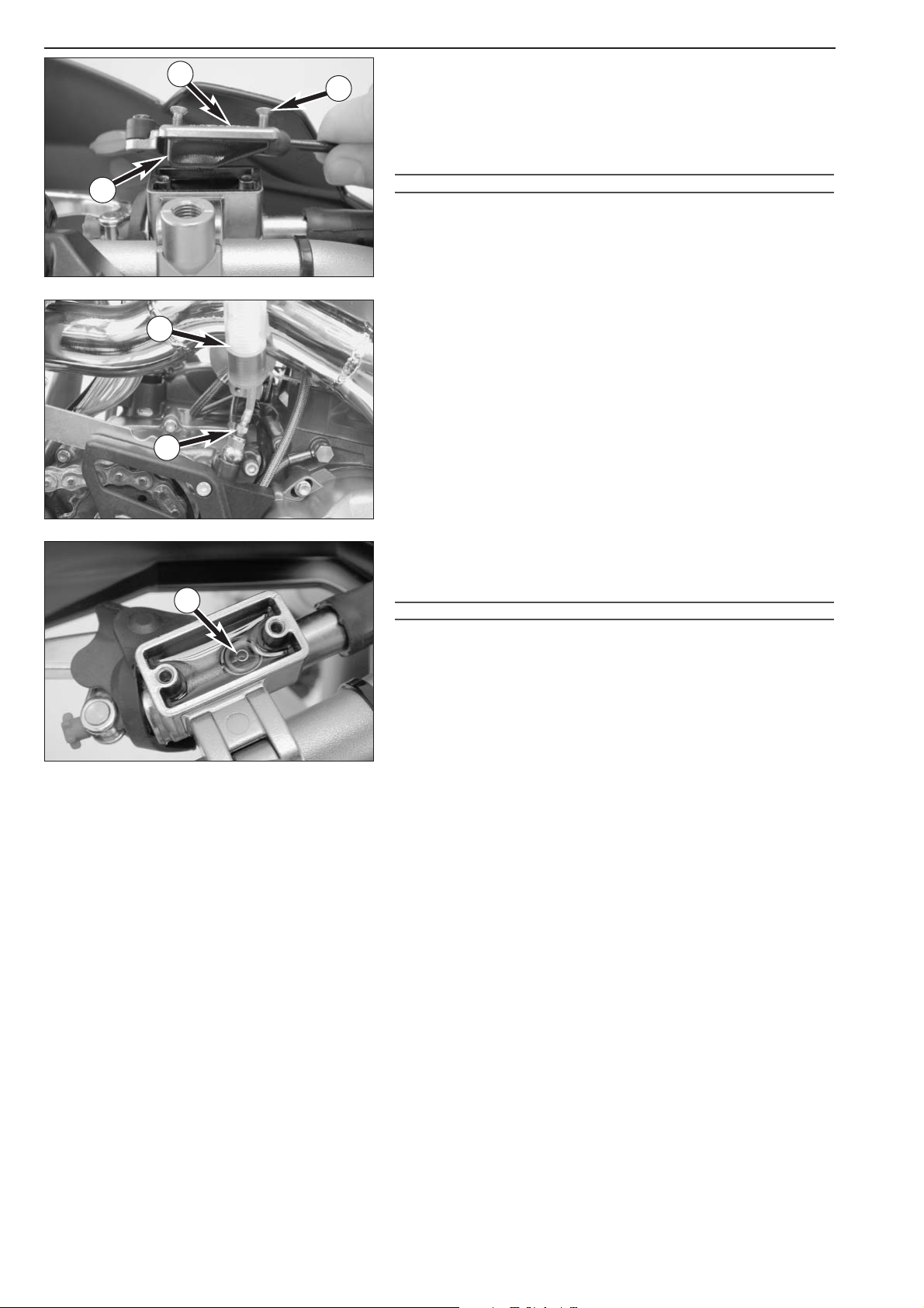
Checking the oil level of the hydraulic clutch
To check the oil level in the master cylinder of the clutch remove the
cover. For this purpose, remove screws
1 and cover 2 together
with the rubber boot
3. The oil level in the horizontal-standing
master cylinder should be 4 mm below the upper edge.
If necessary, fill up with biodegradable hydraulic oil SAE 10 (f.ex.
Motorex Kupplungs-Fluid 75).
!
CAUTION
!
– KTM
USES BIODEGRADABLE HYDRAULIC OIL FOR THE HYDRAULIC CLUTCH
CONTROL
. NEVER MIX BIODEGRADABLE HYDRAULIC OILS WITH MINERAL OILS
.
–A
LWAYS USE BIODEGRADABLE HYDRAULIC OIL SAE 10 TO FILL UP THE MASTER
CYLINDER
. NEVER REFILL WITH MINERAL HYDRAULIC OIL OR BRAKE FLUID.
Bleeding of the hydraulic clutch
To bleed, the cover of the master cylinder of the clutch needs to be
removed. For this purpose, remove screws
1 and take off cover 2
together with rubber bellows 3. At the slave cylinder of the clutch,
remove the bleeder nipple
4. In its place, mount the bleeder syringe 5
which is filled with SAE 10 hydraulic oil. Refill oil until oil is discharged
from the bore
6 of the master cylinder in a bubble-free state. Make
sure that the oil does not overflow. The bleeder syringe can be
purchased from your KTM dealer.
Having completed the bleeding procedure, you have to verify that the
oil level in the master cylinder is correct. If necessary, fill up with
biodegradable hydraulic oil SAE 10 (f.ex. Motorex Kupplungs-Fluid
75).
!
CAUTION
!
– KTM
USES BIODEGRADABLE HYDRAULIC OIL FOR THE HYDRAULIC CLUTCH
CONTROL
. N
EVER MIX BIODEGRADABLE HYDRAULIC OILS WITH MINERAL OILS
.
–A
LWAYS USE BIODEGRADABLE HYDRAULIC OIL SAE 10 TO FILL UP THE MASTER
CYLINDER
. NEVER REFILL WITH MINERAL HYDRAULIC OIL OR BRAKE FLUID.
2
1
3
4
6
5
Page 29
Repair manual KTM LC4 Art.-Nr. 3.206.006 -E
REMOVING THE ENGINE . . . . . . . . . . . . . . . . . . . . . . . . . . . . . . . . . . . . .3-2
REFITTING THE ENGINE . . . . . . . . . . . . . . . . . . . . . . . . . . . . . . . . . . . . . .3-4
REMOVING AND REFITTING ENGINE
INDEX
3-1D
3
Page 30

Page 31
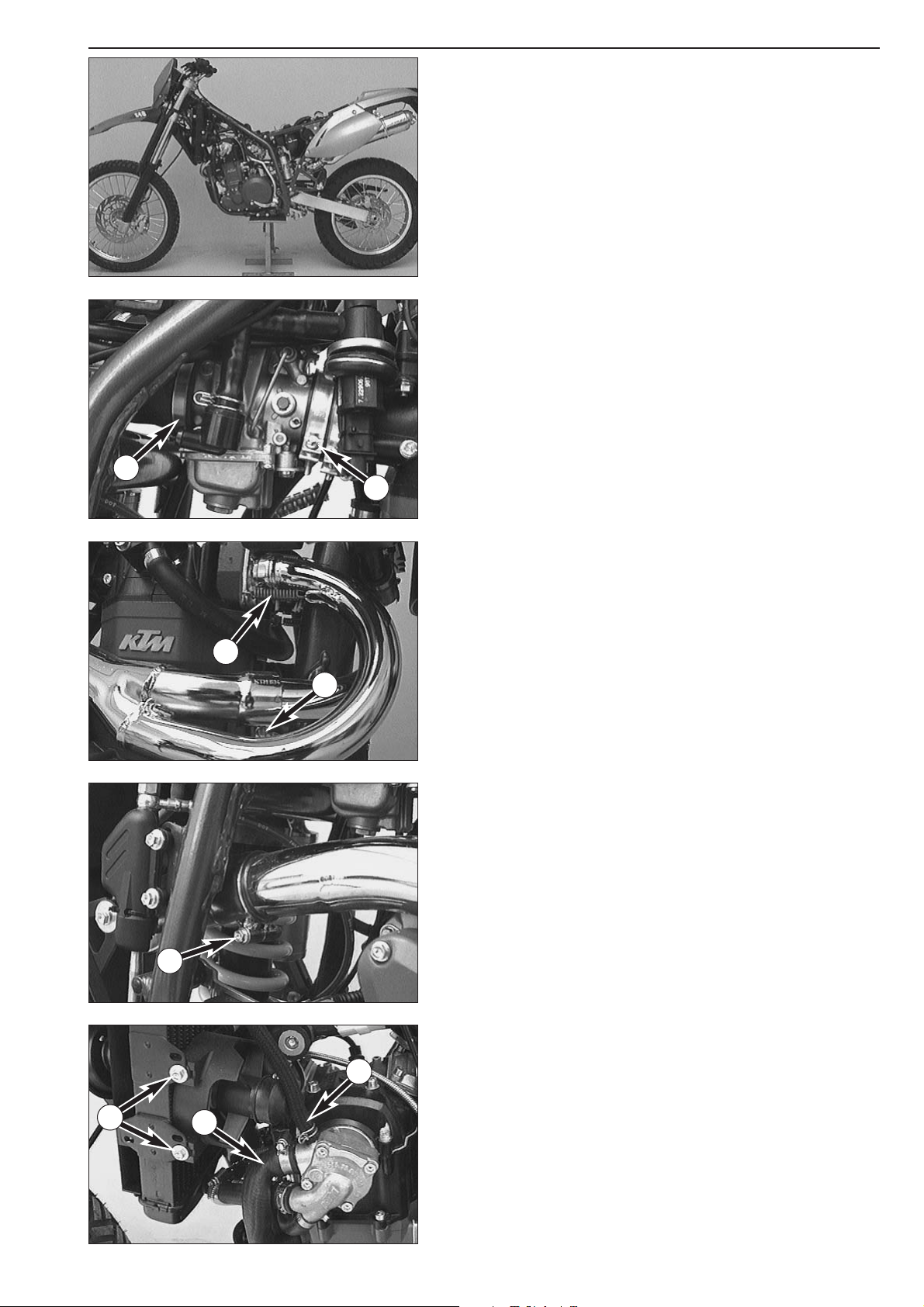
Repair manual KTM LC4 Art.-Nr. 3.206.006 -E
Removing the engine
– Thoroughly clean the entire motorcycle.
– When working on a motorcycle with engine guard, remove the
latter.
– Jack the motorcycle up on a stable supporting device.
– Remove the seat, the side covers as well as the tank and the spoilers.
– Disconnect the negative pole of the battery.
– Undo the 2 hose clamps
1 as well as hose clamp 2. Pull the
carburetor backwards out of the intake flange and swing it aside.
– Unhook the 4 springs
3 at the exhaust manifold.
– Undo bolt
4.
– Undo bolt
5 and remove the exhaust manifold.
– Disconnect water hoses
6 and 7 from the water pump and let out
the cooling liquid.
– Remove the two bolts
8, disconnect and remove the fan.
– Unhook the clutch cable and the decompression cable.
– Disconnect the bleeder hose at the valve cover.
3-2D
1
2
3
4
5
7
8
6
Page 32
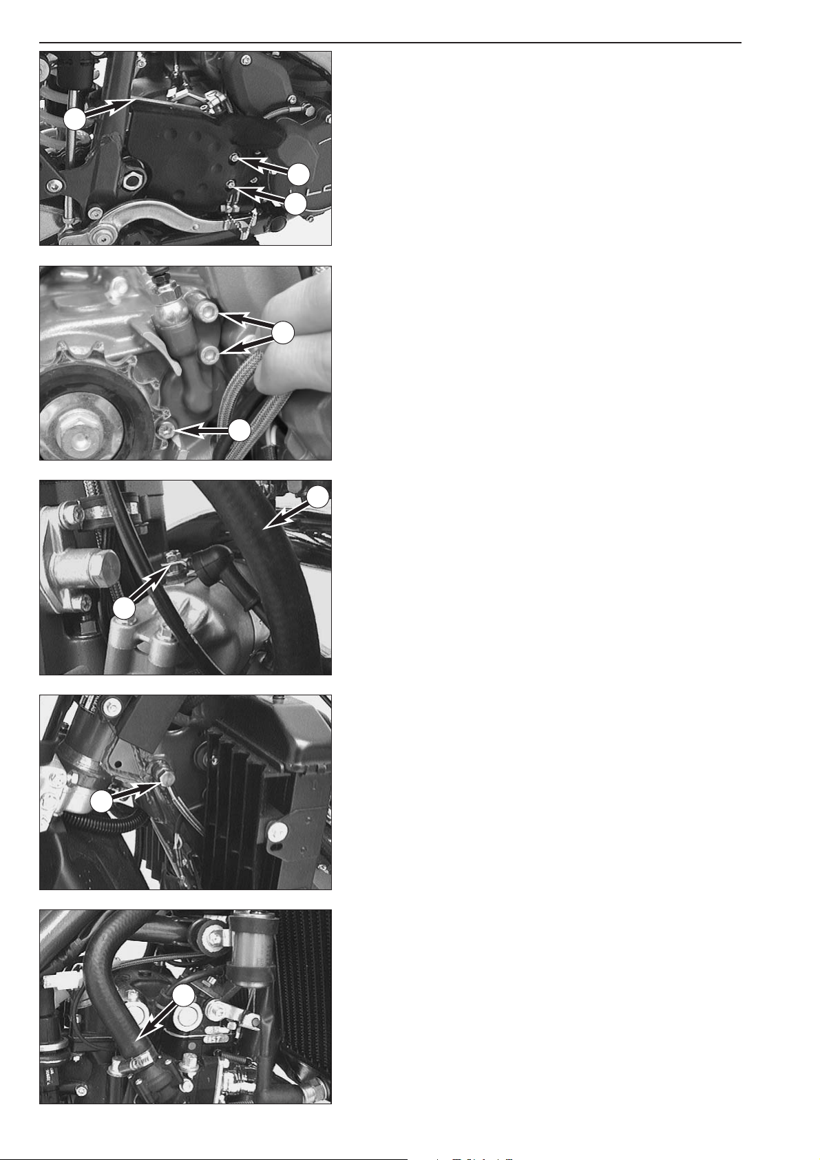
– Remove the two bolts 1 and take off the chain guard.
– Remove the chain damping plate
6.
– Remove the chain joint and take off the chain.
From model 2003 on:
– Remove the 3 bolts
3 of the clutch slave cylinder and pull the clutch
slave cylinder off the casing.
– Disconnect the bleeder hose
4.
– Disconnect the positive cable
5 from the electric starter motor.
– Disconnect all electric plug and socket connections from the engine.
– Remove the banjo bolt
6.
– Disconnect the water hose
7.
3-3D
1
1
2
3
3
4
5
6
7
Page 33
Repair manual KTM LC4 Art.-Nr. 3.206.006 -E
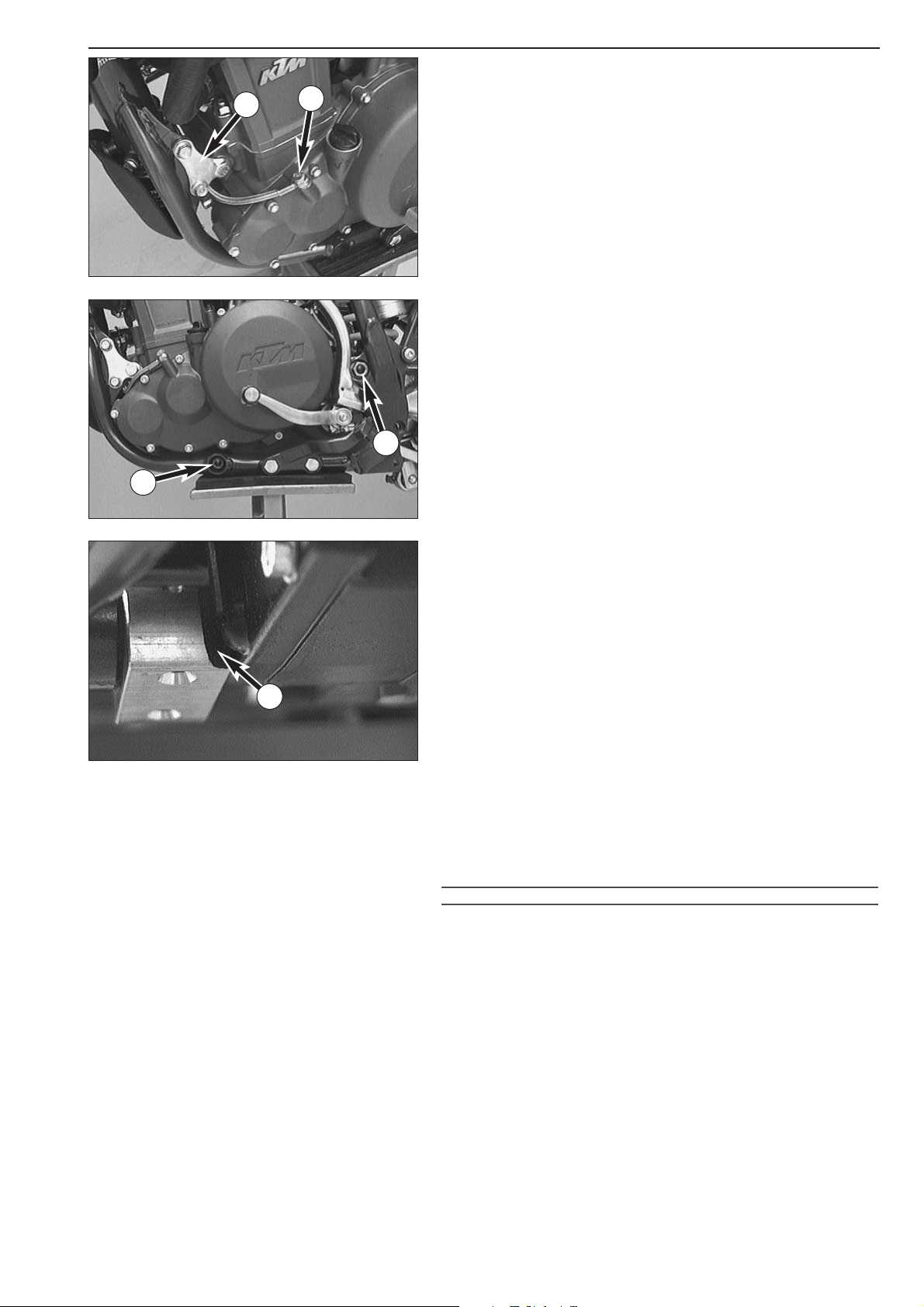
– Remove the jet screw 1.
– Remove the left as well as the right engine retaining bracket
2.
– Remove bolt
3 as well as the swingarm pivot 4.
– Then lift the engine out of the frame.
Installing the engine
NOTE: To install the engine reverse the procedure indicated above.
– When working on a model with an engine guard keep in mind that
opening
A must be located on the right side and face the engine.
Tightening torques:
Swingarm pivot: 100 Nm 74 ft.lb
Engine mounting bolts M8: 40 Nm 30 ft.lb
Engine mounting bolts M10: 70 Nm 50 ft.lb
Banjo bolt (oil pipe on the frame): 15 Nm 11 ft.lb
Jet screw (clutch cover): 10 Nm 7 ft.lb
All other M6 bolts: 10 Nm 7 ft.lb
All other M8 bolts: 25 Nm 19 ft.lb
All other M10 bolts: 45 Nm 33 ft.lb
NOTE: Use only high-quality antifreeze (e.g. Shell Advance Coolant) for
the cooling system. The frame oil should always be changed after
engine repair.
!
CAUTION
!
AFTER INSTALLING THE ENGINE CAREFULLY BLEED THE OIL SYSTEM (SEE OIL CHANGE
INSTRUCTIONS
). DO NOT REV THE ENGINE DURING THE BLEEDING PROCESS !
– The motorcycle can be tested as soon as the engine is running
smoothly. After the test run check and, if necessary, correct all liquid
levels.
3-4D
1
2
3
4
A
Page 34

Page 35

DRAIN ENGINE OIL . . . . . . . . . . . . . . . . . . . . . . . . . . . . . . . . . . . . . . . . .4-2
REMOVING THE ELECTRIC STARTER MOTOR . . . . . . . . . . . . . . . . . . . . .4-2
REMOVING THE CLUTCH RELEASE LEVER AND THE OIL HOSES . . . . . . .4-3
REMOVING THE OIL FILTER . . . . . . . . . . . . . . . . . . . . . . . . . . . . . . . . . . .4-3
REMOVING THE EPC WIRING HARNESS . . . . . . . . . . . . . . . . . . . . . . . . . .4-3
REMOVING THE IGNITION (KOKUSAN 4K-2) . . . . . . . . . . . . . . . . . . . . . .4-3
REMOVING THE IGNITION (SEM) . . . . . . . . . . . . . . . . . . . . . . . . . . . . . .4-5
REMOVING THE IGNITION (KOKUSAN 4K-3) . . . . . . . . . . . . . . . . . . . . . .4-5
REMOVING THE ELECTRIC STARTER DRIVE . . . . . . . . . . . . . . . . . . . . . . .4-6
REMOVING THE CYLINDER HEAD TOP SECTION . . . . . . . . . . . . . . . . . . .4-7
BLOCKING THE CRANKSHAFT . . . . . . . . . . . . . . . . . . . . . . . . . . . . . . . . .4-8
REMOVING THE CAMSHAFT AND THE AUTOMATIC TENSIONER . . . . . .4-8
REMOVING CYLINDER HEAD . . . . . . . . . . . . . . . . . . . . . . . . . . . . . . . . .4-10
REMOVING CYLINDER AND PISTON . . . . . . . . . . . . . . . . . . . . . . . . . . .4-10
REMOVING ENGINE SPROCKET . . . . . . . . . . . . . . . . . . . . . . . . . . . . . . .4-11
REMOVING CLUTCH AND PRIMARY DRIVE . . . . . . . . . . . . . . . . . . . . . .4-11
REMOVING THE OIL PUMPS . . . . . . . . . . . . . . . . . . . . . . . . . . . . . . . . .4-13
REMOVING THE TIMING CHAIN AND THE TIMING GEAR . . . . . . . . . . .4-14
REMOVING THE CLUTCH RELEASE SHAFT . . . . . . . . . . . . . . . . . . . . . . .4-14
PARTING OF ENGINE HOUSING . . . . . . . . . . . . . . . . . . . . . . . . . . . . . . .4-15
REMOVING THE SHIFT MECHANISM . . . . . . . . . . . . . . . . . . . . . . . . . . .4-15
REMOVING THE TRANSMISSION SHAFTS . . . . . . . . . . . . . . . . . . . . . . .4-17
REMOVING THE KICKSTARTER SHAFT . . . . . . . . . . . . . . . . . . . . . . . . . .4-17
Repair manual KTM LC4 Art.-Nr. 3.206.006 -E
DISASSEMBLING THE ENGINE
INDEX
4-1D
4
Page 36

Page 37
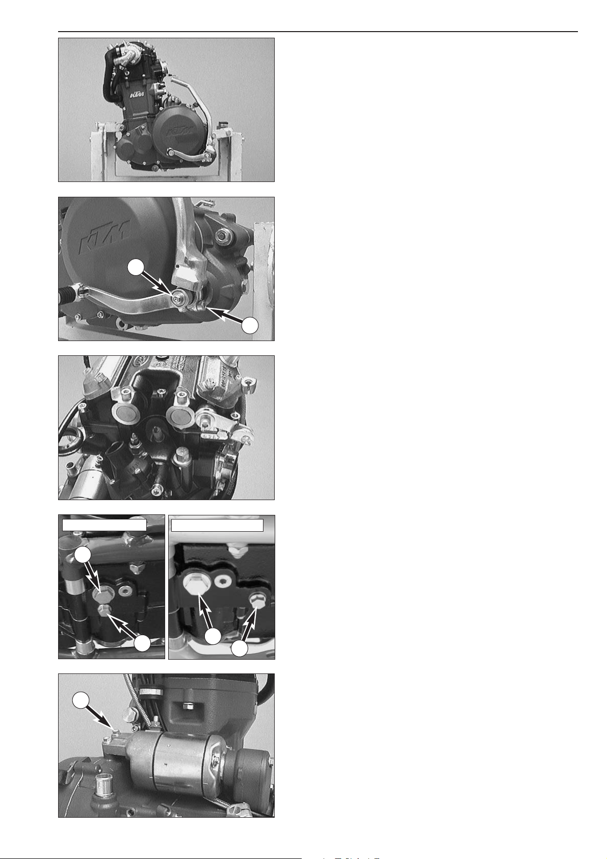
Repair manual KTM LC4 Art.-Nr. 3.206.006 -E
4-2D
– Fit engine to engine work stand.
– Remove bolt
1 together with the washers. Then remove the shift
lever together with the V-seal ring behind.
– Remove bolt
2 together with the washer. Then remove the
kickstarter.
– Remove spark plug
Drain engine oil
– Remove oil drain plug 3 and magnetic plug 4 and drain oil.
Removing the electric starter motor
– Undo 2 bolts 5 and remove the electric starter motor from the
flange.
1
2
5
up to model 2001
from modell 2002 on
3
3
4
4
Page 38

4-3D
Removing the clutch release lever and the oil hoses
– Undo bolt 1 and remove the clutch release lever.
– Remove the two banjo bolts
2 together with the seal rings and
remove both oil hoses.
Removing the oil filter
– Remove all three bolts 3 and take off the oil filter cover together
with the O-ring or gasket.
–Take the oil filter out of the engine housing.
Removing the EPC wiring harness
– Undo the 3 bolts 4 and remove the EPC wiring harness.
Removing the ignition (Kokusan 4K-2)
– Undo 4 bolts and remove the ignition cover with the stator incl.
gasket.
1
2
2
3
4
4
Page 39
Repair manual KTM LC4 Art.-Nr. 3.206.006 -E
4-4D
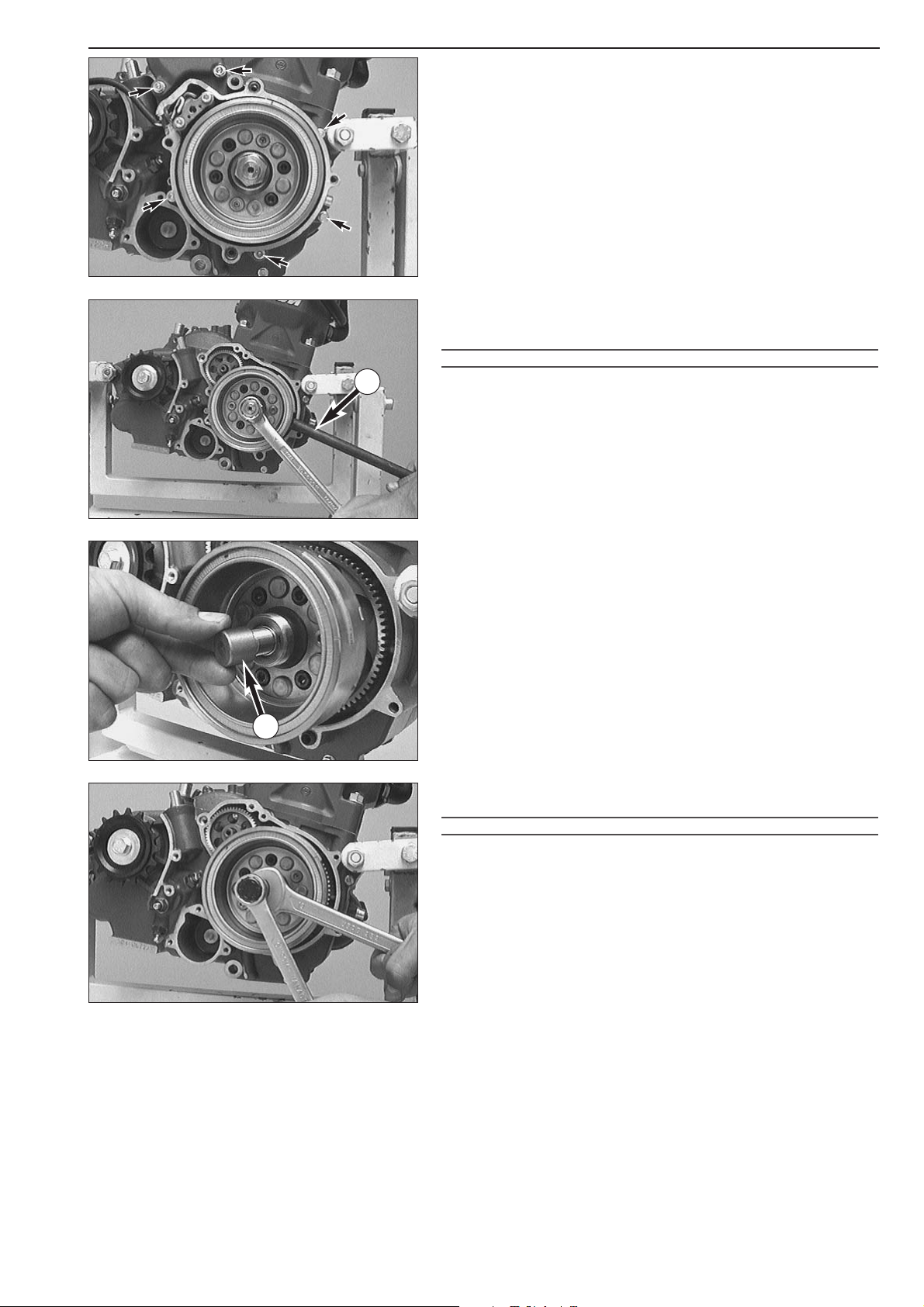
– Undo 6 bolts and remove starter flange incl. gasket.
– Insert the holding spanner
2 into the 2 bores of the flywheel.
– Hold the flywheel and remove the hexagon nut (LH thread).
– Remove the disc.
!
CAUTION
!
TOAVOID DISTORTION OF THE CRANK WEB
, NEVER MOUNT THE CRANKSHAFT
LOCKING BOLT TO STEADY THE FLYWHEEL
.
– Put the protection cover
1 onto the crankshaft and mount the
flywheel extractor.
– Pull off the flywheel and take the woodruff key out of the
crankshaft.
!
CAUTION
!
NEVER USE A HAMMER OR ANY OTHER TOOL ON THE FLYWHEEL TO AVOID
LOOSENING OF THE MAGNETS
.
1
2
Page 40

4-5D
Removing the ignition (SEM)
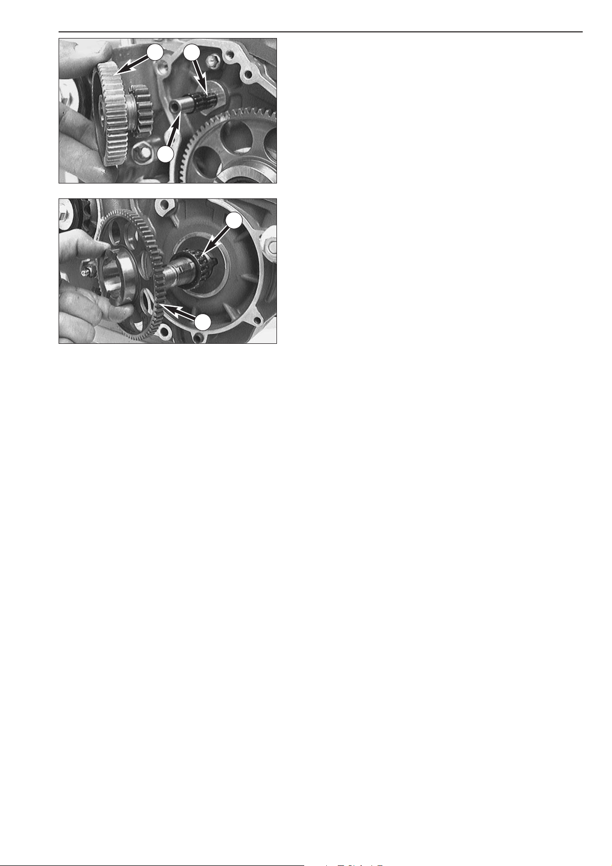
– Undo the 4 bolts and remove ignition cover and O-ring.
– Use the crankshaft locking bolt to block the crankshaft.
– Unscrew collar nut (LH thread) and remove spring disc.
– Fit extractor and pull off flywheel. Use protective sleeve.
– Remove woodruff key from the crankshaft.
–Twist the crankshaft locking bolt out until the crankshaft is no longer
blocked.
!
CAUTION
!
NEVER USE A HAMMER OR ANY OTHER TOOL ON THE FLYWHEEL TO AVOID
LOOSENING OF THE MAGNETS
.
Removing the ignition (Kokusan 4K-3)
– Undo the 4 bolts and take off the ignition cover together with the
O-ring.
– Use the crankshaft locking bolt to block the crankshaft.
– Undo the collar nut (LH thread) and remove the spring washer.
– Mount the extractor and pull off the flywheel.
–Take the woodruff key out of the crankshaft.
–Finally, twist out the crankshaft locking bolt until the crankshaft is no
longer blocked.
!
CAUTION
!
NEVER USE A HAMMER OR SIMILAR TOOL ON THE FLYWHEEL TO PREVENT
LOOSENING OF THE MAGNETS
.
Page 41
Repair manual KTM LC4 Art.-Nr. 3.206.006 -E
Removing the electric starter drive
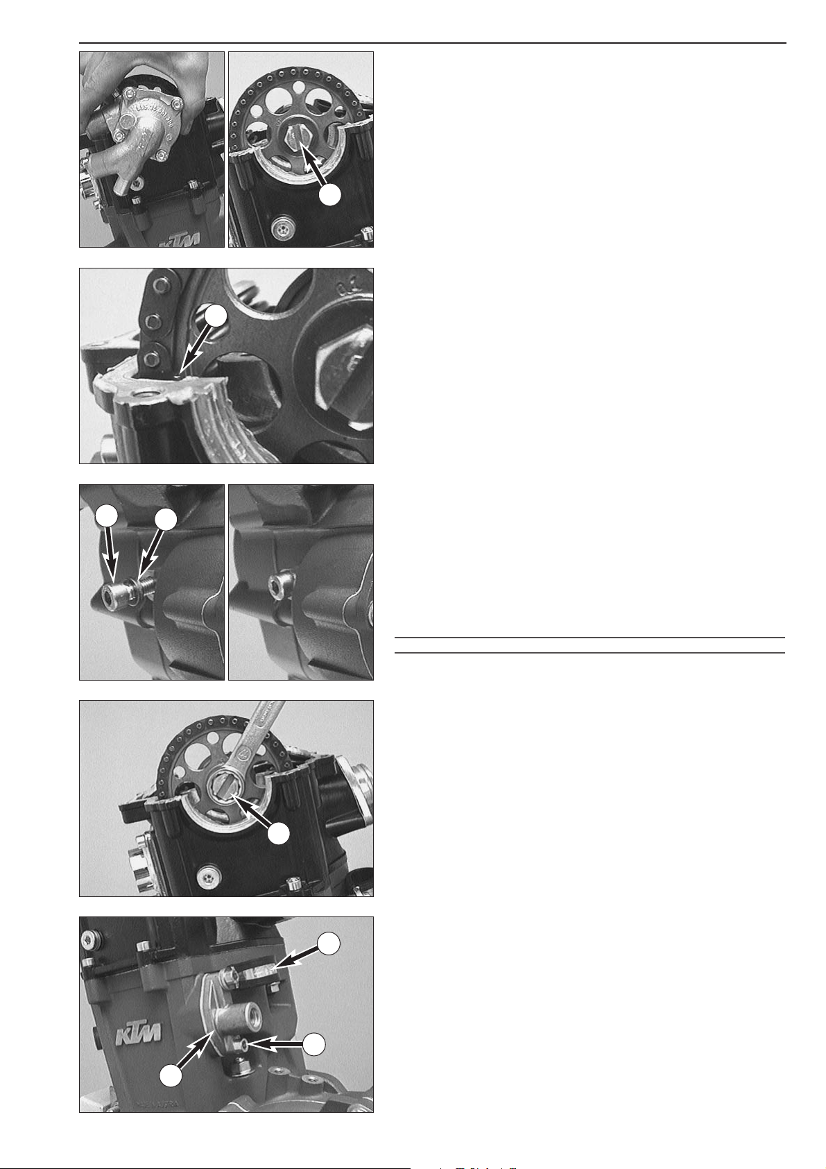
– Pull the reduction gear 1 off the bearing bolt.
– Remove both needle bearings
2 and pull the bearing bolt 3 out of
the engine housing.
– Remove the freewheel gear
4 and the needle bearing 5.
4-6D
1
2
3
4
5
Page 42

4-7D
Removing the cylinder head top section
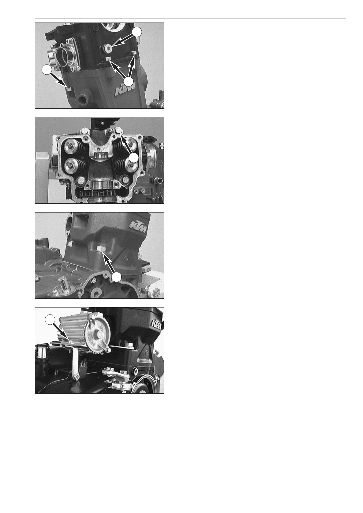
– Unscrew plug 1 with gasket and remove pressure spring from
automatic tensioner.
– Undo the 4 hose clamps and remove both hoses (
2 and 3).
– Remove all 6 bolts
4 together with the seal rings and take off both
valve covers together with the gaskets.
– Remove the hexagon nut
5 and take off the retaining bracket of the
solenoid valve
6.
NOTE: A retaining bracket is only used in engines with EPC.
– Remove all 11 bolts. Then remove the cylinder head top section.
!
CAUTION
!
W
HEN REMOVING CYLINDER HEAD TOP SECTION DO NOT CHOCK IT. THIS WOULD
DAMAGE THE HOUSING OF THE WATER PUMP
.
NOTE: The control valve of SLS models can be removed after undoing
the bolts of the cylinder head top section.
1
2
3
4
5
6
Page 43
4-8D
Repair manual KTM LC4 Art.-Nr. 3.206.006 -E
– Pull water pump upward and simultaneously turn crankshaft.
NOTE: When groove
A in the HH bolt is vertical, the water pump can
be pulled upward and taken out of the cylinder head without the
application of force.
Blocking the crankshaft
–Turn the piston to position TDC (mark B must coincide with the
plane surface of the cylinder head).
– Undo the crankshaft locking bolt
1.
– Remove the copper disc
2.
NOTE: Same engines are equipped with a normal bolt M8x16 and a
copper washer 8x12x1 instead of the crankshaft locking bolt M8 and a
copper washer 8x14x3. In this case the special tool 580.30.080.000
must be used.
– Reinsert crankshaft locking bolt by hand.
– If the bolt does not slide smoothly into its bore, slightly move the
camshaft gear (if cylinder head top section is mounted turn the
flywheel) back and forth until the crankshaft locking bolt engages in
its bore.
–Tighten crankshaft locking bolt with 20 Nm.
!
CAUTION
!
UNDER NO CIRCUMSTANCES APPLY FORCE TO bolt IN CRANKSHAFT LOCKING BOLT
AS THIS WILL DAMAGE THE CRANKSHAFT
.
Removing the camshaft and the automatic tensioner
– Remove the driving bolt 3 together with the two washers.
– Remove the two bolt
4 and take off the automatic tensioner 5 and
the clamp
6.
A
B
1
2
4
3
5
6
Page 44

4-9D
– Using a screwdriver, lever circlip 1 out of the groove.
–Tilt camshaft and remove needle bushing
2.
– While tilted, pull camshaft from camshaft gear and remove together
with grooved ball bearing and circlip.
–Take the camshaft gear out of the timing chain as indicated in the
illustration.
1
2
Page 45
4-10D
Repair manual KTM LC4 Art.-Nr. 3.206.006 -E
Removing cylinder head
–
Unscrew chain guide bolt 1 incl. gasket, bolts 2 and collar nuts 3.
– Unscrew the 4 collar bolts 4 and detach cylinder head with gasket.
Removing cylinder and piston
– Unscrew the 4 collar nuts at the cylinder base 5.
– Remove cylinder and cylinder base gasket.
– When working on an engine with a microfilter, remove the AH bolt
6 before taking off the cylinder.
– Disconnect the oil hose at the clutch cover and remove the
microfilter together with the holder.
6
1
3
4
5
2
Page 46

4-11D
– Remove two wire circlips and press piston pin out of piston.
– Remove piston.
Removing engine sprocket
– Remove collar bolt 1 and spring washer.
– Remove the sprocket from the counteshaft.
– Remove the distance bushing from the countershaft.
NOTE: If the gear-box and the clutch of the engine are in good
condition, throw it into gear in order to block the take-off shaft
(frictional connection to the blocked crankshaft is present). If the takeoff shaft cannot be blocked as described above, a chain sprocket holder
must be applied for the removal of the chain sprocket nut.
Removing clutch and primary drive
– Remove the 11 bolts and detach clutch cover with gasket.
– Unscrew the bolts
3 of the clutch crosswise to prevent the clutch
discs from jamming when the springs are relieved of tension.
– Remove bolts, spring retainer and springs.
– Remove pressure cap with push rod.
– Remove the disc package and take the O-ring
2 also off the inner
clutch hub.
2
1
3
Page 47

4-12D
Repair manual KTM LC4 Art.-Nr. 3.206.006 -E
– Release the lock washer of the inner clutch hub.
– Put the clutch holder
1 onto the inner clutch hub and undo the
hexagon nut (see illustration).
– Remove the clutch holder.
–Take the hexagon nut, the lock washer and the inner clutch hub off
the main shaft.
–Try to turn the outer clutch hub in both directions to check the
absorbing elements. Dead travel in either direction is inadmissible.
–Take the outer clutch hub and the needle bearing
2 off the main
shaft.
– Remove the kickstarter intermediate gear
3.
– Unscrew hexagon nut of primary gear wheel and detach spring
washer from the crankshaft.
– Fit extractor for primary gear and pull off primary gear.
1
2
3
Page 48
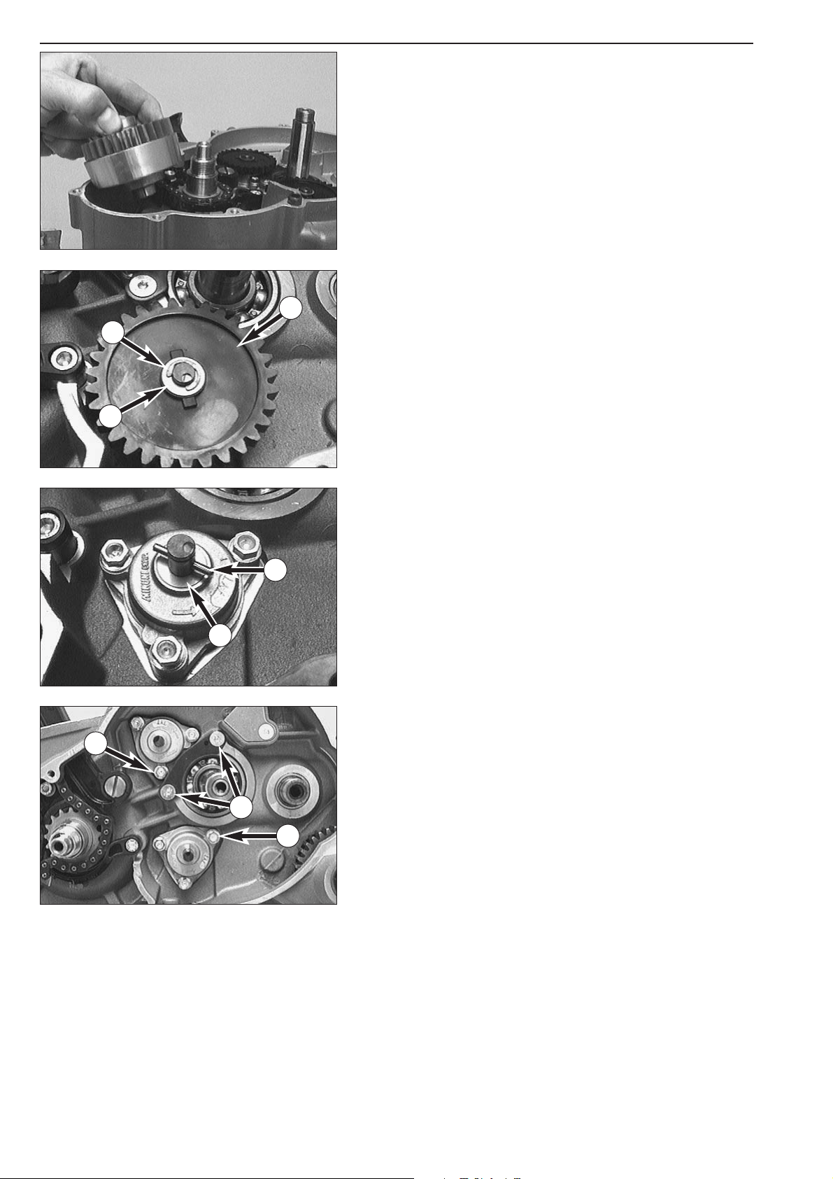
4-13D
– Remove the balancer shaft from the bearing by hand.
Removing the oil pumps
NOTE: The following procedure must always be performed on both oil
pumps.
– Remove the locking washer
1.
– Remove stop disc
2 and the oil pump gear 3.
– Remove the needle roll
4 and stop disc 5.
–Twist out the 6 bolts
6 and remove the oil pumps from the housing.
NOTE: For better access to bolt
7 remove bolts 8 and take off the
retaining bracket.
1
2
4
6
7
3
5
8
Page 49
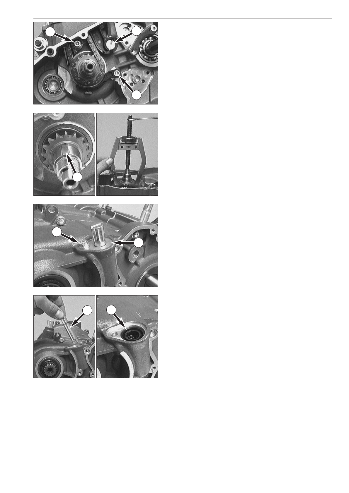
4-14D
Repair manual KTM LC4 Art.-Nr. 3.206.006 -E
Removing the timing chain and the timing gear
– Remove allan head bolt 1 and remove timing chain guide from the
casing.
– Unscrew flat-head screw
2 and remove timing chain tensioner.
– Unscrew allan head bolt
3 and remove timing chain securing guide.
– Insert timing chain into the clutch compartment of the engine
housing and disengage from timing gear.
– Remove the primary gear woodruff key
4 from the crankshaft.
–Withdraw the timing pinion from crankshaft with a 2-jaw puller.
–Take the woodruff key of the timing gear out of the crankshaft.
Removing the clutch release shaft
– Remove bolt(s) 5 and take off the retaining bracket 6.
– Pull the clutch release shaft
7 out of the housing.
– Remove the grooved ring
8.
1
2
3
4
5
6
7
8
Page 50
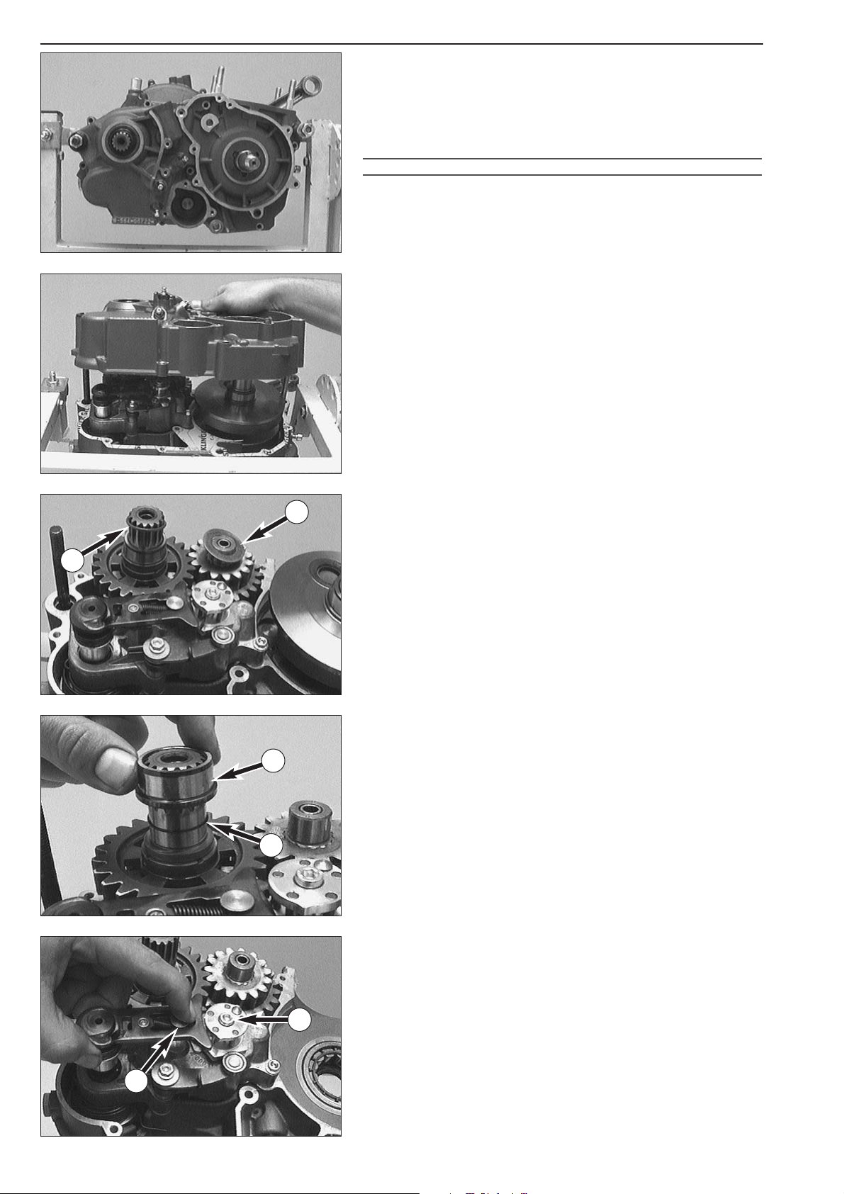
4-15D
Parting of engine housing
– Loosen the crankshaft locking bolt.
–Tip ignition side upwards and remove all the housing bolts.
– Release engine mount on engine repair stand.
– Lift right hand housing half with suitable tools bearing on the bosses
provided, or part with a few light plastic mallet blows against the
counter shaft.
!
CAUTION
!
LEVERING APART WITH A SCREW
-
DRIVER OR SIMILAR TOOL MUST BE AVOIDED, SINCE
THE SEALING SURFACES ARE EASILY DAMAGED
.
– Remove housing-half and gasket.
–Take the stop disc
1 off the main shaft (can stick to the inside of the
housing).
–Take the O-ring
2 off the countershaft.
– Remove the crankshaft from the bearing by hand.
–Take the inner ring 3 of the roller bearing and the O-ring below 4
off the countershaft.
Removing the shift mechanism
– Push back slide plate 5 and pull shift shaft out of the kickstarter
shaft.
– Remove allan head bolt
6 and detach locking piece.
1
2
3
4
5
6
Page 51
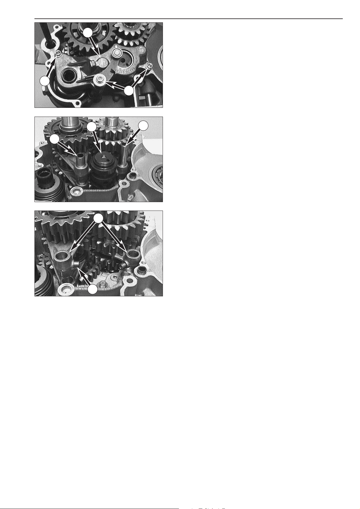
4-16D
Repair manual KTM LC4 Art.-Nr. 3.206.006 -E
– Remove the 3 bolts 1 and detach the shift mechanism support 2.
– Pull out the shift rails
3 and swing the shift forks aside, taking care
of the shift rolls
6 on the driving pins of the shift forks.
– Pull the shift roller
4 out of the bearing seat.
–Take the shift forks
5 together with the shift rolls 6 out of the
engine housing.
NOTE: Although the counter shaft shift forks are identical they should
be refitted in the same position as before if reused. Therefore mark
accordingly upon removal.
1
1
2
3
3
4
5
6
Page 52
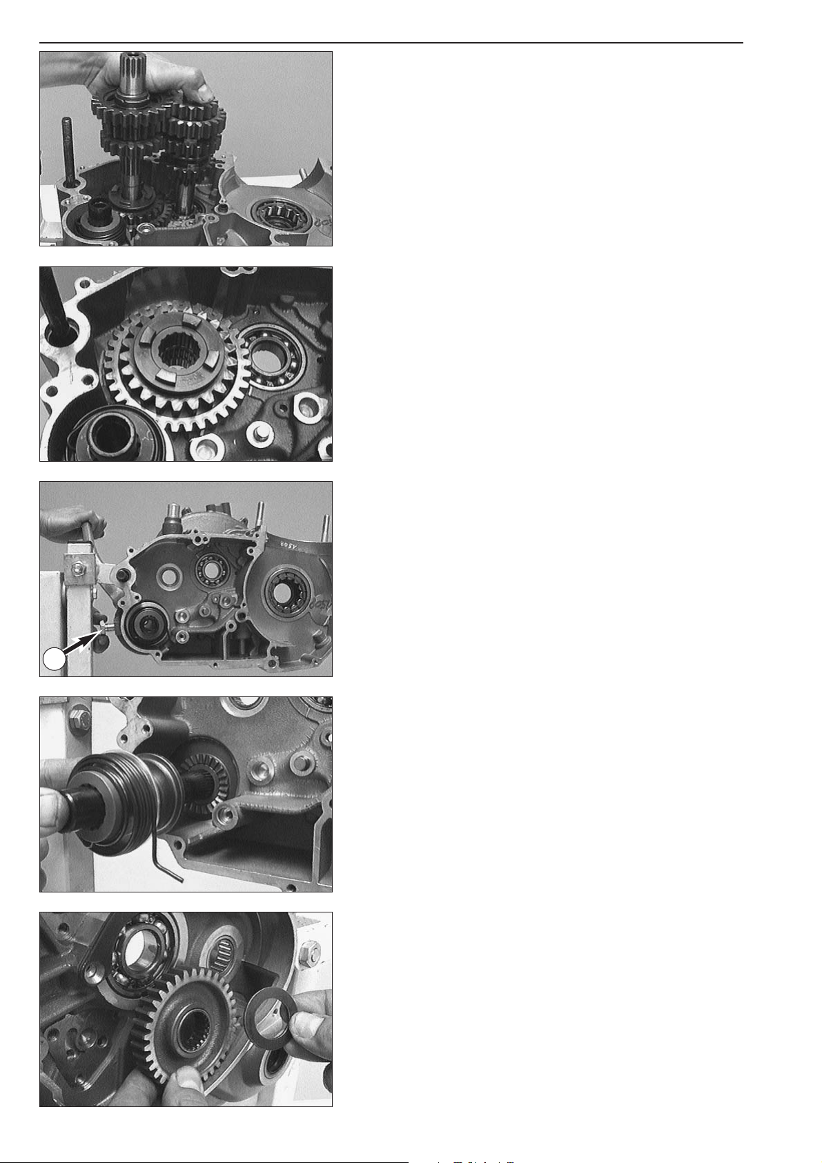
4-17D
Removing the transmission shafts
– Pull both transmission shafts out of the bearing seats.
–Take the 3rd gear/sliding gear and the 1st gear/idler gear out of the
engine housing together with the needle bearing and the stop disc.
NOTE: A roller bearing was installed in the 660 SMC model, thus a stop
disc is unnecessary.
Removing the kickstarter shaft
– Put kickstarter onto kickstarter shaft and hold in this position.
– Unscrew stop bolt
1 and relieve starter spring tension by releasing
the kickstarter.
– Remove kickstarter shaft assembly from housing.
–Take the starter gear out of the housing bag together with the
needle bearing and the stop discs.
– Clean all parts and check for wear, replace if necessary.
NOTE: When an engine is completely overhauled it is recommended
that all gaskets, shaft seal rings, O-rings and, possibly, all bearings are
renewed.
1
Page 53

WORKING ON THE RIGHT HOUSING HALF . . . . . . . . . . . . . . . . . . . . . . .5-3
WORKING ON THE LEFT HOUSING HALF . . . . . . . . . . . . . . . . . . . . . . . .5-5
CRANKSHAFT . . . . . . . . . . . . . . . . . . . . . . . . . . . . . . . . . . . . . . . . . . . . .5-6
MEASURING AND ADJUSTING OF CRANKSHAFT AXIAL PLAY . . . . . . . . .5-7
CHECKING THE PISTON . . . . . . . . . . . . . . . . . . . . . . . . . . . . . . . . . . . . . .5-7
MOUNTING INSTRUCTIONS FOR PISTON RINGS . . . . . . . . . . . . . . . . . . .5-8
PISTON RING END GAP . . . . . . . . . . . . . . . . . . . . . . . . . . . . . . . . . . . . . .5-8
MEASURING PISTON AND CYLINDER, DETERMINING
THE PISTON FITTING CLEARANCE . . . . . . . . . . . . . . . . . . . . . . . . . . . . . .5-8
CYLINDER – NIKASIL COATING . . . . . . . . . . . . . . . . . . . . . . . . . . . . . . . .5-9
RECOATED CYLINDER . . . . . . . . . . . . . . . . . . . . . . . . . . . . . . . . . . . . . . .5-9
DISASSEMBLING THE CYLINDER HEAD AND CHECKING
THE COMPONENTS FOR WEAR . . . . . . . . . . . . . . . . . . . . . . . . . . . . . . .5-10
DISASSEMBLING THE CYLINDER HEAD TOP SECTION AND
CHECKING COMPONENTS FOR WEAR . . . . . . . . . . . . . . . . . . . . . . . . .5-11
PRE-ASSEMBLING THE CYLINDER HEAD TOP SECTION . . . . . . . . . . . . .5-11
CHECKING THE COMPONENTS OF THE TIMING MECHANISM FOR WEAR
. . .5-12
DISASSEMBLING THE CAMSHAFT AND CHECKING THE
COMPONENTS FOR WEAR . . . . . . . . . . . . . . . . . . . . . . . . . . . . . . . . . .5-12
PRE-ASSEMBLING THE CAMSHAFT . . . . . . . . . . . . . . . . . . . . . . . . . . . .5-12
AUTOMATIC TENSIONER . . . . . . . . . . . . . . . . . . . . . . . . . . . . . . . . . . . .5-13
PREASSEMBLY OF AUTOMATIC TENSIONER . . . . . . . . . . . . . . . . . . . . .5-13
DISASSEMBLING THE OIL PUMPS AND CHECKING THE
COMPONENTS FOR WEAR . . . . . . . . . . . . . . . . . . . . . . . . . . . . . . . . . .5-13
OIL LINES (SX, SXC) . . . . . . . . . . . . . . . . . . . . . . . . . . . . . . . . . . . . . . . .5-14
OIL LINES (SC) . . . . . . . . . . . . . . . . . . . . . . . . . . . . . . . . . . . . . . . . . . . .5-14
OIL LINES (660 SMC) . . . . . . . . . . . . . . . . . . . . . . . . . . . . . . . . . . . . . . .5-15
OIL LINES (MODELS WITH FRAME OIL) . . . . . . . . . . . . . . . . . . . . . . . . .5-15
CHECKING THE KICKSTARTER COMPONENTS FOR WEAR . . . . . . . . . . .5-16
PREASSEMBLY OF KICKSTARTER SHAFT . . . . . . . . . . . . . . . . . . . . . . . . .5-16
CLUTCH COVER . . . . . . . . . . . . . . . . . . . . . . . . . . . . . . . . . . . . . . . . . .5-16
REPLACING ABSORBING ELEMENTS OF THE OUTER CLUTCH HUB . . . .5-16
Repair manual KTM LC4 Art.-Nr. 3.206.006 -E
SERVICING ON INDIVIDUAL COMPONENTS
INDEX
5-1D
5
Page 54

CHECKING THE CLUTCH COMPONENTS FOR WEAR . . . . . . . . . . . .5-17
CHECKING THE SHIFT MECHANISM COMPONENTS FOR WEAR
. . . .5-18
PREASSEMBLY OF SHIFT SHAFT . . . . . . . . . . . . . . . . . . . . . . . . . . .5-18
SHIFT MECHANISM SUPPORT . . . . . . . . . . . . . . . . . . . . . . . . . . . .5-19
BALANCER SHAFT . . . . . . . . . . . . . . . . . . . . . . . . . . . . . . . . . . . . .5-19
DISASSEMBLING AND REASSEMBLING THE WATER PUMP . . . . . . . .5-19
IMPORTANT NOTE REGARDS WORKING ON TRANSMISSION . . . . .5-20
ASSEMBLING THE MAIN SHAFT . . . . . . . . . . . . . . . . . . . . . . . . . . .5-20
ASSEMBLING THE COUNTER SHAFT . . . . . . . . . . . . . . . . . . . . . . . .5-21
REMOVING THE INTERMEDIATE GEAR . . . . . . . . . . . . . . . . . . . . . .5-22
CHECKING THE FREEWHEEL . . . . . . . . . . . . . . . . . . . . . . . . . . . . . .5-22
REPLACING THE FREEWHEEL HUB . . . . . . . . . . . . . . . . . . . . . . . . .5-22
ELECTRIC STARTER MOTOR . . . . . . . . . . . . . . . . . . . . . . . . . . . . . .5-22
IGNITION (KOKUSAN 4K-2) . . . . . . . . . . . . . . . . . . . . . . . . . . . . . .5-23
CHECKING THE STATOR AND THE PULSE GENERATOR (KOKUSAN
4K-2
)
. . .5-23
REPLACING THE STATOR (KOKUSAN 4K-2) . . . . . . . . . . . . . . . . . . .5-23
IGNITION (SEM) . . . . . . . . . . . . . . . . . . . . . . . . . . . . . . . . . . . . . .5-24
CHECKING THE STATOR (SEM) . . . . . . . . . . . . . . . . . . . . . . . . . . . .5-24
REPLACING THE STATOR (SEM) . . . . . . . . . . . . . . . . . . . . . . . . . . .5-24
CHECKING THE STATOR (KOKUSAN 4K-3) . . . . . . . . . . . . . . . . . . .5-25
REPLACING THE STATOR (KOKUSAN 4K-3) . . . . . . . . . . . . . . . . . . .5-25
INDEX
5-2D
IMPORTANT NOTE REGARDS WORKING ON ENGINE HOUSING
Read through the following section before commencing work. Then determine the assembly sequence so
that the engine housing halves only need to be heated up once before replacing the bearings.
Having first removed the dowels, in order to expel the bearings or remove them with light mallet blows,
the housing halves must be placed on a suitably large plane surface, supporting the whole of the sealing
surface without damaging it. A wooden panel is best used as a base.
Bearings or shaft seal rings should not be hammered into their seats. If no suitable press is available,
use a suitable mandrel and hammer them in with great care. Cold bearings will practically drop into
their seats at an engine housing temperature of approx. 150° C.
After cooling, should the bearings fail to lock in the bore, they are bound to rotate after warming. In
that event the housing must be replaced.
Page 55
Repair manual KTM LC4 Art.-Nr. 3.206.006 -E
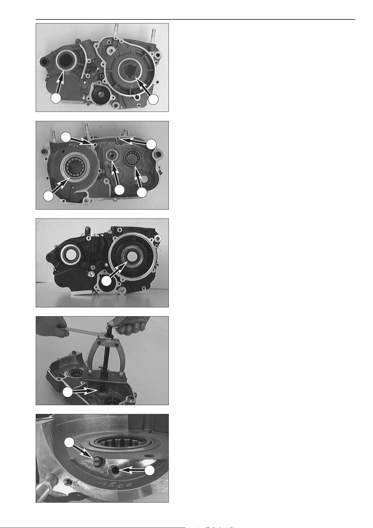
Working on the right housing half
Remove shaft seal rings and heat housing half to approx. 150° C by
means of a hot-plate.
Roller bearing of crankshaft
1
Proceed as for left housing half.
Cylinder roller bearing of counter shaft
2
Remove shaft seal ring. Press old bearing inwards. Press in new bearing
from inside as far as stop.
Oil ducts
3
Use compressed air to clean all oil ducts. Ensure that the oil ducts are
not clogged.
Counter shaft seal ring
4
Press in new shaft seal ring from outside until flush.
Crankshaft seal ring
8
Press in new shaft seal ring from outside until flush.
NOTE: Engine with an electric starter have a stop disk instead of the
shaft seal ring
5. Do not remove this disk.
Needle bearing of main shaft
6
Pull old bearing from bearing seat using bearing extracto and insert. In
order to apply the bearing extractor in an vertical position, a steel plate
(see special tools) must be laid on the sealing area of the housing. The
bearing extractor jaws should fit as close as possible up to the housing
walls. Then press in new bearing from inside until flush.
Oil nozzle
7
For the cleaning of the oil nozzle and the oil duct simply blow it
through with compressed air from the nozzle side. If the oil nozzle is
disassembled, secure it with Loctite 243 when mounting again.
Then check the lubrication bore
A of the crankshaft roller bearing for
free passage.
After the case half has cooled down, check bearings for secure fit.
5-3D
1
2
3
3
5
4
6
6
7
A
8
Page 56

Needle bushes of the clutch disengagement
– Pull out the needle bushes of the clutch disengagement with a gear
puller and insert from the housing half.
– Oil the needle bushes.
–Press the first needle bush
A to stop.
–Press the second needle bush
B so that it is flush.
5-4D
A
B
Page 57
Repair manual KTM LC4 Art.-Nr. 3.206.006 -E
5-5D
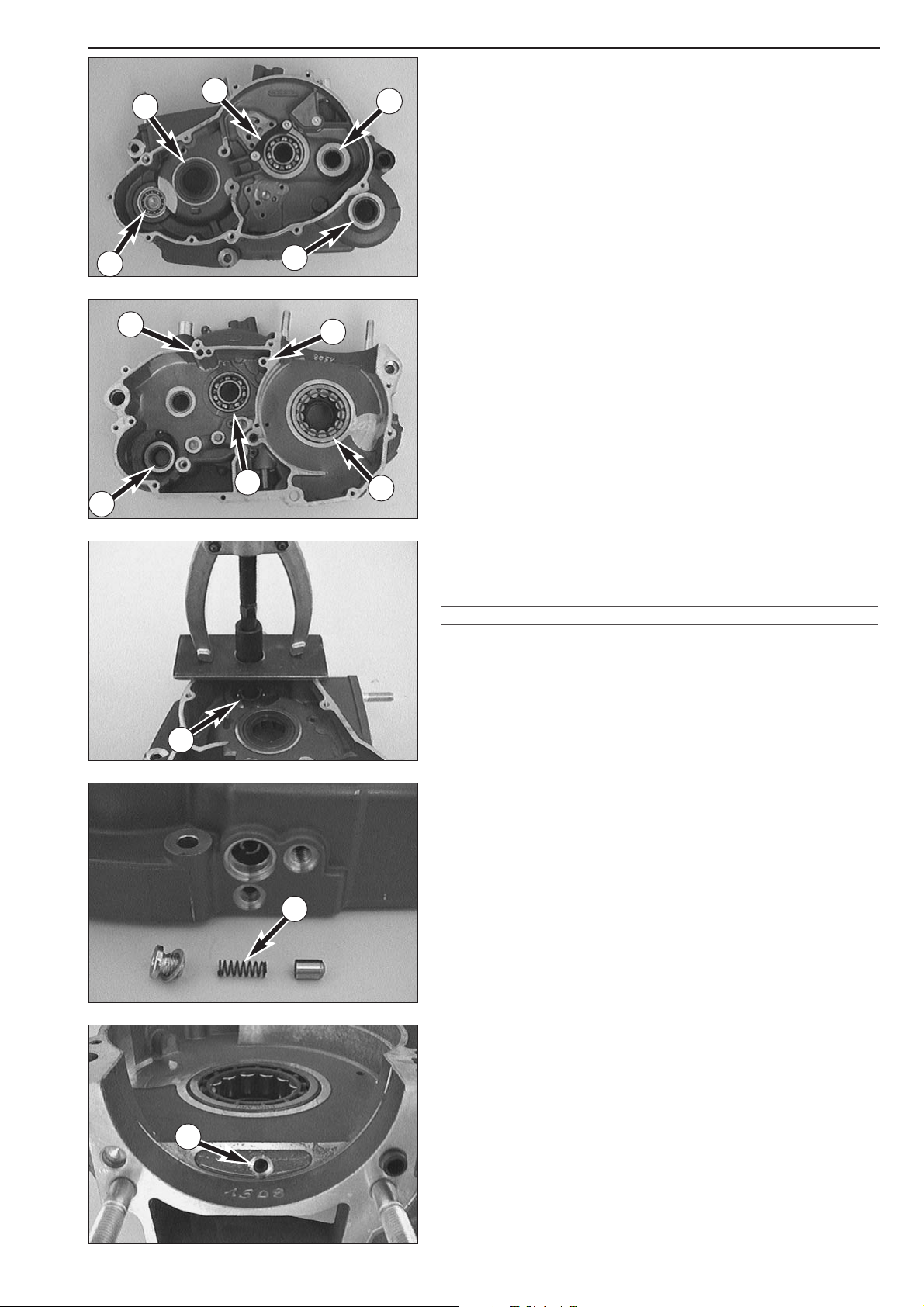
Working on the left half of the housing
Remove shaft seal rings and heat housing half to approx. 150° C by
means of a hot-plate.
Needle bearing of counter shaft
1
Press in new needle bearing from inside until flush.
Shaft seal ring of kickstarter shaft
2
Press in new shaft seal ring from outside with sealing lip facing inwards
until flush.
Grooved ball bearing of the balancer shaft
3.
Use an extractor and insert to remove the grooved ball bearing from
the housing half.
Shaft seal ring of crankshaft
4
Press in new shaft seal ring from outside with sealing lip facing inwards
until flush.
Retaining plate for main shaft grooved ball bearing
5
If the retaining plate has been removed, use Loctite 243 for the two
countersunk bolts during assembly.
Oil ducts
6
Use compressed air to clean all oil ducts. Ensure that the oil ducts are
not clogged.
Roller bearing of crankshaft
7
From outside press crankshaft roller bearing inwards using a suitable
mandrel.
Press in new roller bearing from inside up to the stop.
Grooved ball bearing of main shaft
8
Press in new grooved ball bearing from inside up to the stop.
!
CAUTION
!
DO NOT USE FORCE WHEN PRESSING THE GROOVED BALL BEARING AGAINST THE
RETAINING PLATE
5 TO AVOID A BENDING OF THE PLATE, WHICH WOULD RESULT IN
EXCESSIVE AXIAL PLAY OF THE MAIN SHAFT
.
Needle bearing of kickstarter shaft
9
Press in new needle bearing from inside until flush.
Bypass valve
Test valve piston, tight fit and pressure spring for damage.
Minimum length of the pressure spring
bk: 23,5 mm
NOTE: The opening pressure of the bypass valve is reduced when the
length of the pressure spring decreases below 23,5 mm. This reduces
the oil pressure and causes engine damage.
Ensure that neither the lubrication bore of the roller bearing A nor the
oil ducts of the oil pumps are clogged.
– After the housing half has cooled down, check bearings for tight fit.
–Finally, insert both dowels so that the dowel with internal diameter
15.4 mm is mounted at the rear (swingarm pivot).
10
A
1
2
3
4
5
6
7
8
6
9
3
Page 58
5-6D
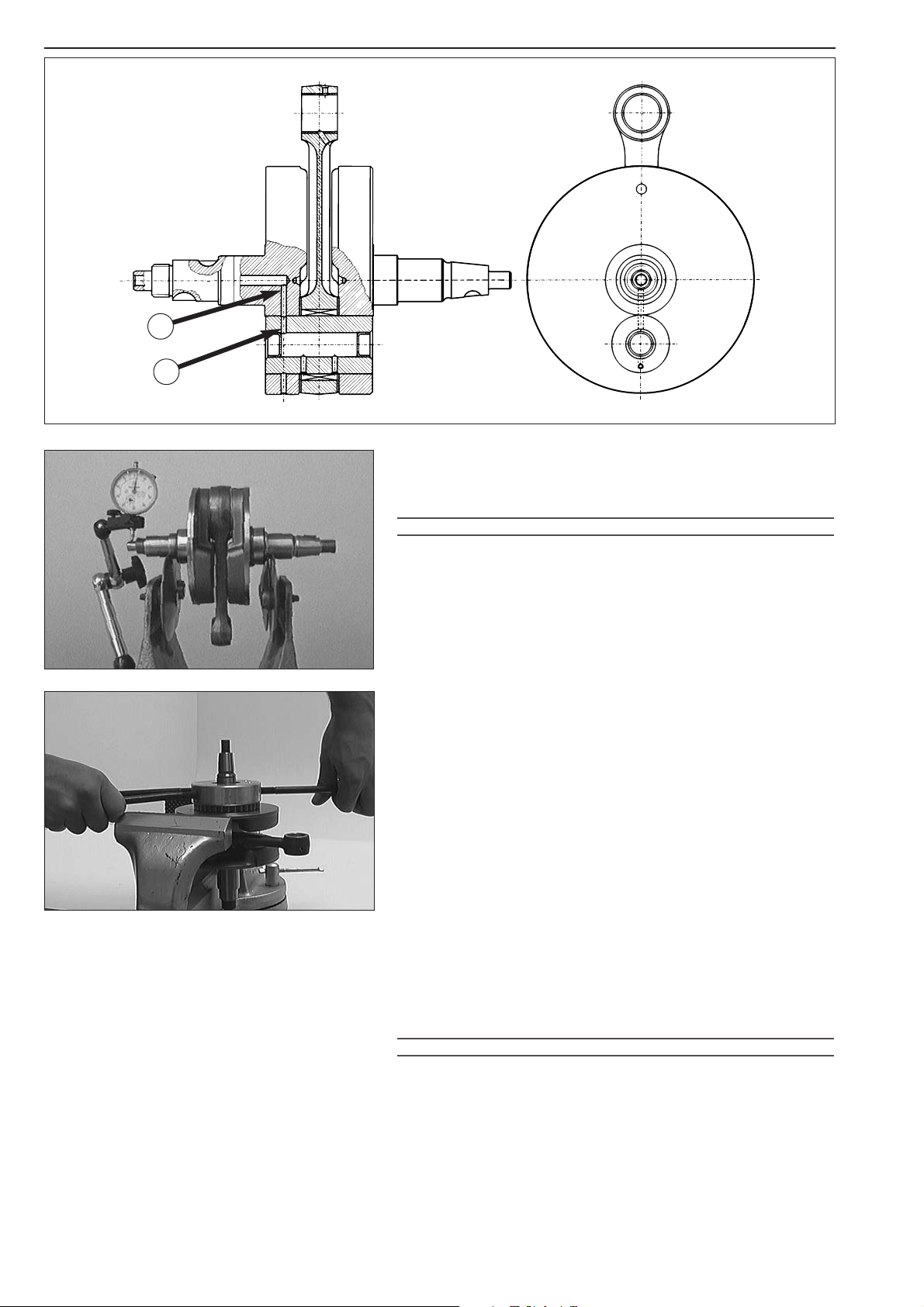
Crankshaft
If the conrod bearing is replaced, take care to properly position the
crankpin. The bores of the crank web
B and crank pin C must
coincide.
!
CAUTION
!
IF THE CRANK PIN IS PRESSED IN THE WRONG POSITION, THE CONROD BEARING IS
SUPPLIED INSUFFICIENTLY OR NOT AT ALL WITH ENGINE OIL
, WHICH RESULTS IN
BEARING DAMAGE
.
If the crankshaft is continued to be used, check crankshaft journals for
run out. Place crankshaft on a roller block or a similar device and check
the outer end of the journals for run out with a dial gauge.
run out of crankshaft journals: max. 0.04 mm (0.0016 in)
The radial clearance and axial clearance on the conrod bearing must be
checked.
radial clearance: max. 0.05 mm (0.0019 in)
axial clearance: max. 1.00 mm (0.04 in)
– If the crankshaft roller bearings are replaced, the inner rings on the
crankshaft should also be changed.
– Heat special tool on a heating pad up to approx. 150°C and slip it on
the inner ring immediately. Press the special tool together tightly to
obtain a good heat transfer and pull the inner ring off the crankshaft.
–To mount the new inner ring, heat the special tool again to approx.
150°C, engage the inner ring and slip it on the crankshaft journal
immediately.
– In order to safely press on new rings, a middle panel should be
inserted between the crankshaft webs. This panel should be big
enough to be supported on both sides, so that the crankshaft lies
free and accessible.
NOTE: Because LC4-E models have different diameters of inner
crankshaft bearing rings, it is necessary to have both special tools
(584.29.037.040 and 584.29.037.043).
!
CAUTION
!
NEVER CLAMP THE CRANKSHAFT WITH A CRANKSHAFT JOURNAL OR WEB IN THE
VICE
, AND NEVER TRY TO KNOCK THE INNER RING FREE. THE CRANKSHAFT WEBS
MAY BE COMPRESSED THEREBY MAKING THE CRANKSHAFT UNUSEABLE
.
B
C
Page 59

Repair manual KTM LC4 Art.-Nr. 3.206.006 -E
5-7D
Measuring and adjusting of crankshaft axial clearance
– Should the crankshaft, engine housing, or a roller bearing be
replaced, the axial clearance of the crankshaft should also be
checked.
– The housing should be laid inside upwards, then measure the
distance from the sealing area to the inner rings of the roller
bearings. Note the readings and then add on 0.3 mm to allow for
gasket thickness.
– Measure the crankshaft at touching points and then subtract the
measured value from the housing dimensions. This figure will be the
axial play of the crankshaft, which should be 0.03- 0.12 mm (0.001-
0.005 in).
EXAMPLE:
Left-hand housing half 33.0 mm 1.300 ( in)
Right-hand housing half + 32.8 mm 1.290 ( in)
Gasket + 0.3 mm 0.012 ( in)
Total housing dimension = 66.1 mm 2.602 ( in)
Crankshaft dimension – 65.8 mm 2.590 ( in)
Axial play present = 0.3 mm 0.012 ( in)
The compensating washers should be equally distributed between the
two sides of the crankshaft. In our example, one compensation washer
(≠ 0.1 mm / 0.004 in.) must be mounted on either side.
Checking the piston
– Replace the piston in the case of excessive oil consumption or
grooves in the piston skirt.
– If reinstalling the old piston perform the following steps:
1. Piston bearing surface - check for damage
2. Piston ring grooves - the piston rings must move easily in the
groove. Old piston rings or sandpaper (400 grit) may be used to
clean the piston ring grooves.
3. Piston rings - check for damage and end gap (see below).
4. The piston pin must move freely in the piston when mounted. If the
piston pin changed its color badly or shows running traces, it must
be replaced. Insert piston pin also into the conrod and check for
clearance. Maximum clearance in the conrod eye 0.08 mm (0.003
in).
NOTE: When in place, the piston pin may not have any play. It must be
possible to shift it with slight counterpressure.
Page 60
5-8D
Mounting instructions for piston rings
– Insert the oil scraper ring in the lower ring groove. Side of ring
marked facing piston head.
–Mount compression ring (tapered compression piston ring) in middle
ring groove. Side of ring marked facing piston head.
– Insert the compression ring (rectangular ring) in the upper piston ring
groove (the surface marked must be on top).
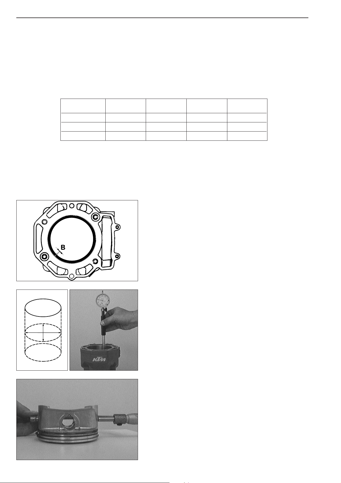
Piston ring end gap
– Insert pisto ring into the cylinder and adjust. Piston ring must be
approx. 10 mm (1/2 inch) from top of cylinder.
– The end gap
B can now be checked which a feeler gauge.
Compression rings: max. 0.60 mm (0.023 in)
Oil scraper ring: max. 0.80 mm (0.03 in)
If the end gap is greater check piston and cylinder for wear. If piston
and cylinder wear are within the permitted tolerance limits, replace the
piston ring.
Measuring piston and cylinder, determining the piston fitting clearance
– In order to determine the wear of the cylinder, measure the cylinder
center of the running area with a micrometer.
– Measure the diameter of the x-axis and the y-axis in order to check
for oval wear, if any.
– The piston is measured on the piston skirt across to the piston pin as
shown in the illustration.
– The cylinder diameter minus the piston diameter yields the piston
assembly clearance.
Piston assembly clearence: see Technical Specification
ELKO ELKO ELKO ARIAS
Ø 89 mm Ø 95 mm Ø 101 mm Ø 101 mm
Compression ring O O O N 100
Tapered ring TOP TOP TOP N 101
Oil scraper ring ELKO TOP TOP –––
x
y
Page 61
Repair manual KTM LC4 Art.-Nr. 3.206.006 -E
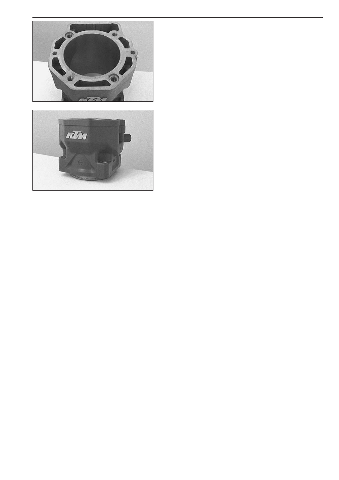
Cylinder – nikasil coating
Nikasil is the brand name for a cylinder coating process, developed by
the piston manufacturer Mahle. The name is derived from the two
materials used in this process - a nickel layer into which the particularly
hard silicon carbide is embedded. The main advantages of the Nikasil
coating are excellent heat dissipation and thus better power output, low
wear and low weight of the cylinder. The worn coating can be
regenerated at low cost provided that the running surface of cylinder is
flawless.
Recoated cylinder
If the Nikasil coating of your cylinder is worn but undamaged, you may
obtain a recoated cylinder at your KTM dealer (new Nikasil coating on
used cylinder).
It may be that your spare cylinder shows color changes on the exterior
side.
5-9D
Page 62
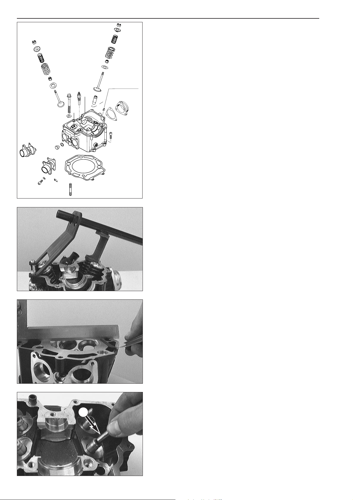
Disassembling the cylinder head and checking the components for wear
– Mount cylinder head in vice using the studs. Do not allow it to rest
on sealing surface.
– Mark valves and remove using special tool (see illustration).
– Clean all parts.
Sealing area
Check spark plug threads and valve seats for damage or cracks. Check
the sealing area to the cylinder for distortions with a straightedge and a
feeler gauge. Distortion limit 0.10 mm (0.004 in).
Valve guides
The valve guides are checked with a limit plug gauge
1 (Ø 7.05 mm).
If the limit plug gauge can be easily inserted into the valve guide, the
guide must be replaced in a specialized workshop.
Valve seats
The valve seats must not be pocketed. Seat sealing width: intake max.
1.5 mm (0.059 in); exhaust max. 2.0 mm (0.079 in). Grind valves if
necessary.
Valves
Check valve heads for wear and run out. Max. run-out on valve heads
0.03 mm (0.001 in). Valve seats should not be pocketed. The sealing
area must be located in the center of the valve seat. The valve stem is
hard-chrome plated. Experience shows that wear appears primarily on
the valve guide.
Valve springs
Only visual check for breakage or wear is necessary.
Valve stem seals
Always renew valve stem seals when the valves are removed.
Intake flange
Check flange surface for distortion, scrape on glas plate if necessary.
5-10D
1
Three-Bond Dichtmasse
Three-Bond Gasket
Page 63
Repair manual KTM LC4 Art.-Nr. 3.206.006 -E
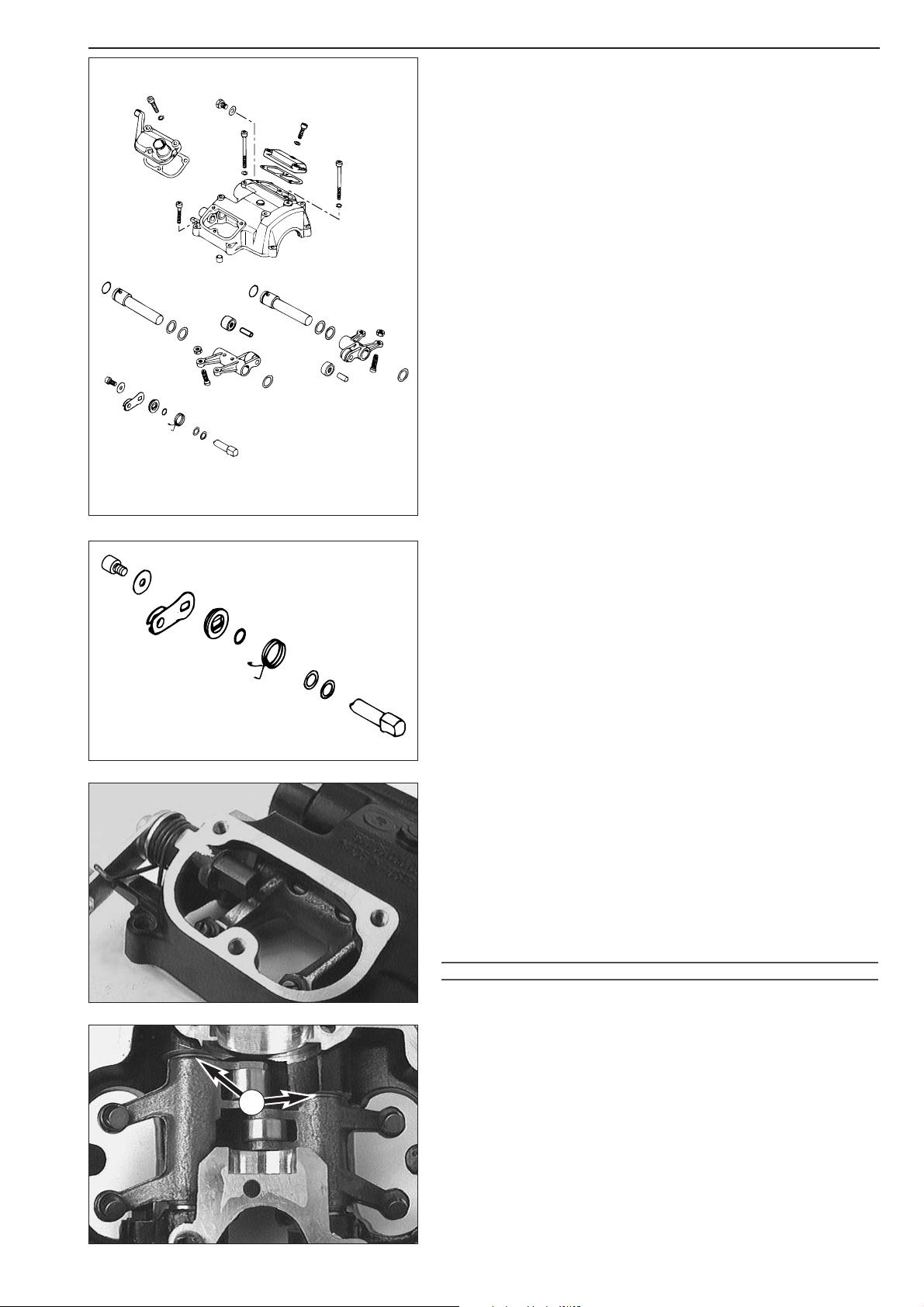
Disassembling the cylinder head top section and checking
the components for wear
– Simply pull the rocker arm axles 1 out of the cylinder head top
section. Then take both rocker arms
2 together with thrust washers
3 and bn out of the cylinder head top section.
Undo bolt
4 and remove
the following components: Washer
5
Decompression shaft lever 6
Covering disc 7
O-ring 8
Decompression lever spring 9
–Press the decompression shaft bk inwards and take it out of the
cylinder head top section together with the washers
bl.
– Clean all components.
Rocker arm shafts
1
The rocker arm shafts must be free of grooves and should turn easily
within the rocker arms
2.
Rocker arm rollers
bm
The rocker arm rollers must move smoothly. Rocker arm rollers must be
removed in the case of radial clearance.
Adjusting screws
bo
The contact surfaces of the adjusting screws must be plane.
Decompression shaft
bk
Check for smooth operation and clearance in the bearing bore.
Pre-assembling the cylinder head top section
– Insert decompression shaft bk with compensation washers bl into the
top section.
– Mount the new O-ring
8, the decompression lever spring 9 and
the cover disc
7 in such a way that the O-ring fits into the recess of
the cover disc.
– Mount the decompression shaft lever
6.
– Apply Loctite 243 to the thread of bolt
4 and mount the bolt
together with washer
5.
– Hook the decompression lever spring onto the decompression shaft
lever.
!
CAUTION
!
THE DECOMPRESSION SHAFT MUST EXHIBIT NO AXIAL PLAY WHEN THE ALLAN HEAD
BOLT
4 IS TIGHTENED
. TO ENSURE THAT THE O-RING
8 f
ORMS A SEAL, IT MUST BE
SLIGHTLY PRESSED AGAINST THE TOP SECTION BY THE COVER DISC
7. HOWEVER,
THE PRESSURE ON THE O-RING MUST NOT BE EXCESSIVELY HIGH AS THE
DECOMPRESSION SHAFT WILL BECOME SLUGGISH
. ADJUST OUT WITH
COMPENSATION WASHERS
bl IF NECESSARY.
NOTE: Discs
bl are available 0.15 mm, 0.30 mm and 0.50 mm thick.
– Mount new O-rings
bp on rocker arm shafts 1.
– Mount rocker arms
2, thrust washers 3 and rocker arm shafts 1.
– On the side of the water pump one thrust washer
bn ≠ 1.0 mm (0.04
in) must be mounted.
– The axial play on the opposite side is roughly equalized with thrust
washers
3 ≠ 1.0 (0.04 in) and ≠ 0.5 mm (0.02 in).
The axial clearance of the rocker arm axles must be 0.20 - 0.30 mm.
5-11D
13
3
1
1
12
15
15
10
12
14
14
2
13
3
2
6
7
8
9
10
11
4
5
13
Page 64
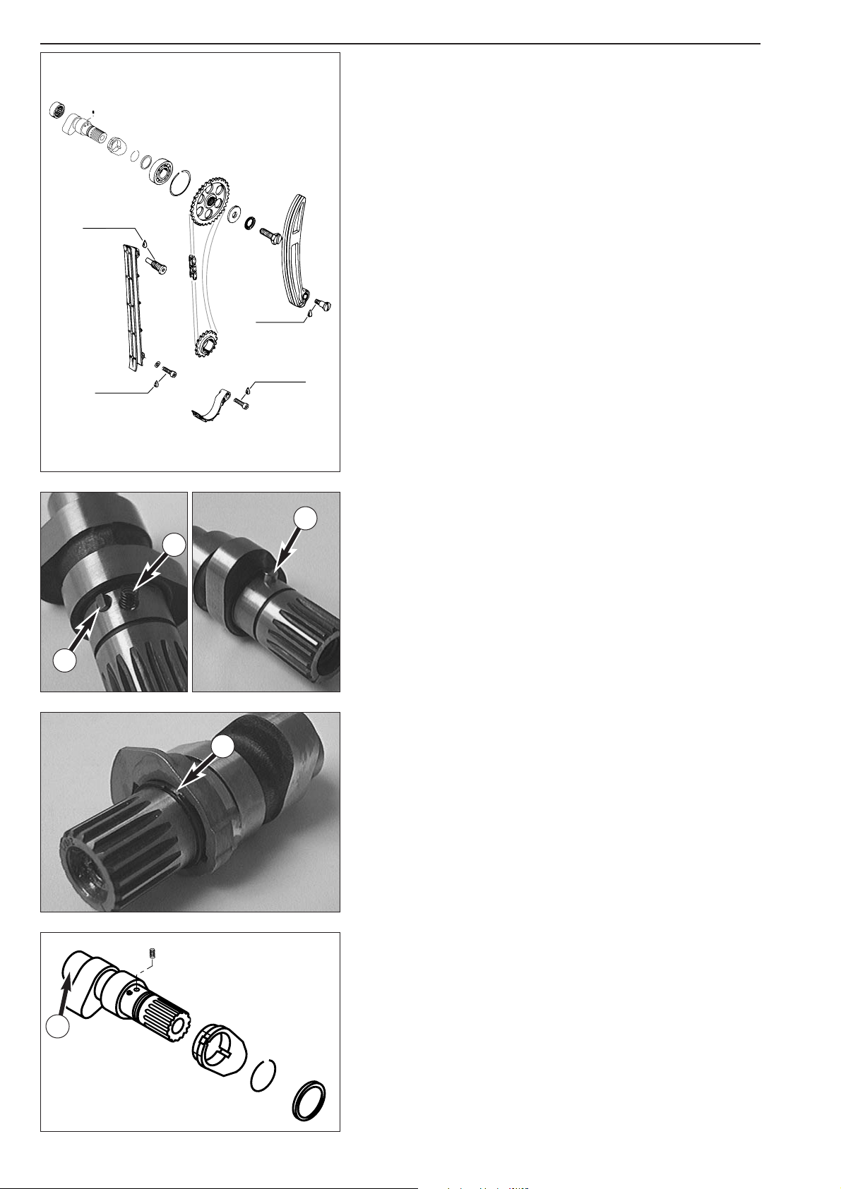
Checking the components of the timing mechanism for wear
Timing chain guide 1
Check for signs of wear.
Timing chain tensioner
2
Check for signs of wear.
Timing chain
3
Check rollers for smooth operation and signs of wear.
Timing gear
4
Check teeth for signs of wear.
Camshaft gear
5
Check teeth for signs of wear.
Grooved ball bearing
6
Check clearance.
Safety device
7
Check for signs of wear.
Camshaft
8
Check pivot points and running surfaces for signs of wear.
Disassembling the camshaft and checking the components for wear
– Remove both the stepped ring bo and the circlip bp. Carefully
remove the decompression cam
bm. Keep a watch on the spring 9.
Supporting pin
bk
Check for signs of wear.
Guide pin
bl
Check for signs of wear.
Decompression cam
bm
Check the contact surfaces towards the supporting pin for signs of
wear.
Spring
9
Check length (minimum length: 7.0 mm/0.275 in).
Camshaft
bn
Check for signs of wear at pivot point A. Minimum diameter of the
pivot point 19.97 mm.
Preassembling the camshaft
– Place spring 9 in the bore, compress and slide decompression cam
bm over it.
– Mount circlip
bp with the sharp side towards the decompression cam.
– Position the open side
B of the circlip between the open spaces of
the decompression cam.
– Slide the step ring
bo with open spaces over the lock washer.
5-12D
8
13
9
12
15
14
6
4
5
2
7
1
3
9
10
11
B
A
LOCTITE 243
LOCTITE 243
LOCTITE 243
LOCTITE 243
Page 65
Repair manual KTM LC4 Art.-Nr. 3.206.006 -E
5-13D
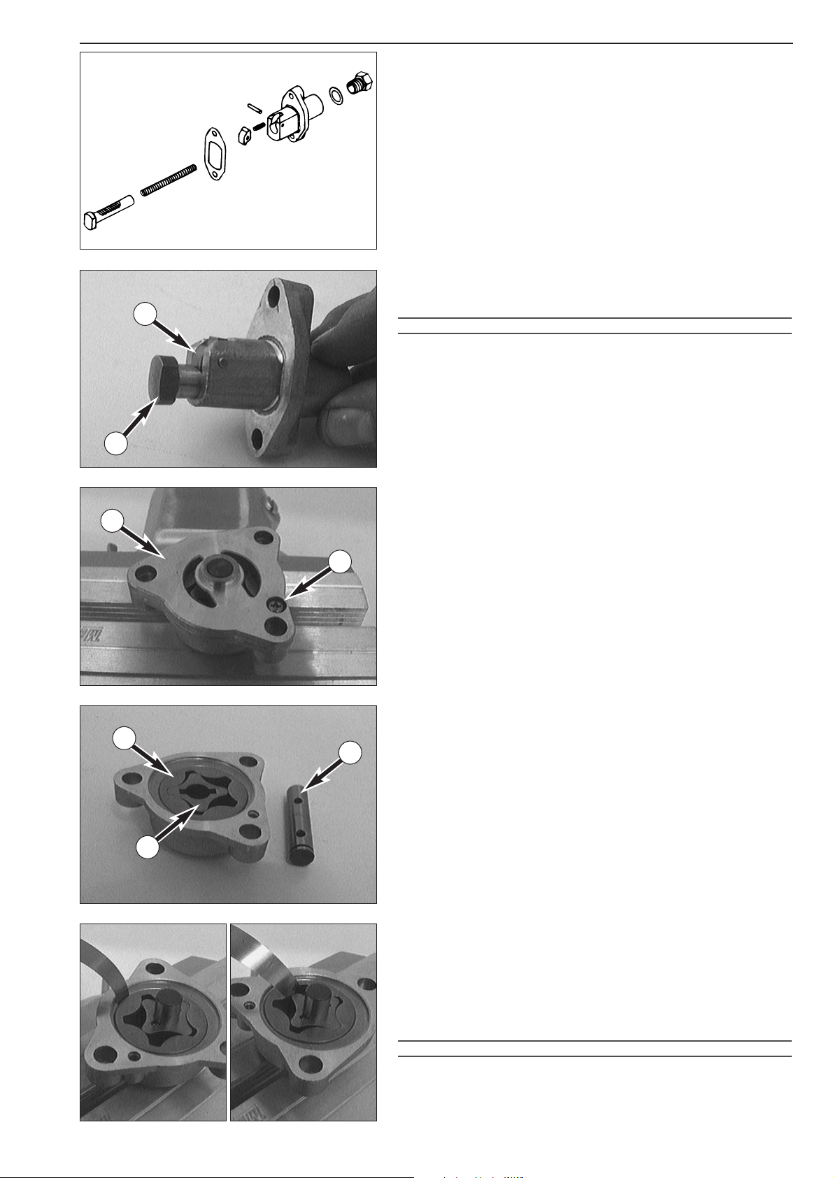
Automater.tensioner
– Check ratcheting pawl 1 for smooth operation and wear.
– Check thrust bolt
2 for wear at.teeth.
Preassembly of automater.tensioner
– Insert thrust bolt into.tensioner housing and engage ratcheting pawl
into.first notch (see illustration).
!
CAUTION
!
IF THE RATCHETING PAWL IS NOT ENGAGED INTO THE FIRST NOTCH THIS WILL CAUSE
EXCESSIVE TENSION OF THE CHAIN
.
Disassembling the oil pumps and checking the components for wear
NOTE: The two oil pumps are similar in design but work at.different
speeds. Disassemble and check the oil pumps separately to.avoid mixing
up of components.
– Remove screw
3 and take off the oil pump cover 4.
– Pull the oil pump shaft
5 out of the oil pump housing together with
the bearing needle.
–Take the inner rotor
6 and the outer rotor 7 out of the oil pump
housing.
– Clean all components and check for signs of wear.
– When reassembling the unit insert the inner rotor and the outer rotor
into.the oil pump housing, making sure that the point faces the
inside.
– Mount oil pump shaft and bearing needle
– Now perform the following measurements to.determine the degree
of wear:
Outer rotor - oil pump housing: max. 0.20 mm
Outer rotor - inner rotor: max. 0.20 mm
– Fill the oil pump housing with oil and mount the oil pump cover.
– Apply Loctite 243 to.the thread of screw
3 and mount the screw.
!
CAUTION
!
FILL OIL PUMPS WITH OIL BEFORE PREASSEMBLING.
1
2
2
1
3
4
5
6
7
Page 66
5-14D
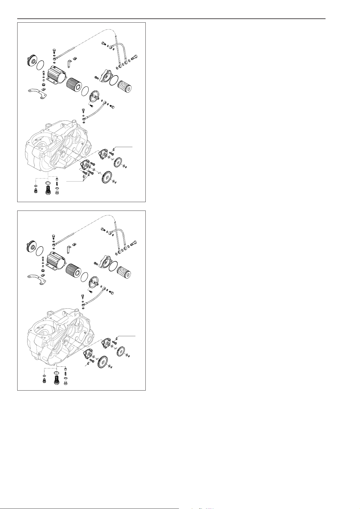
Oil lines (SX, SXC)
– Check oil lines and banjo bolts for damage and clear passage.
– When repairing the engine, the microfilter
1 and the oil filter 2
must be replaced.
Oil lines (SC)
– Check oil lines and banjo bolts for damage and clear passage.
– When repairing the engine, the microfilter
3 and the oil filter 4
must be replaced.
3
4
1
2
LOCTITE 243
0
5
1
LOCTITE 243
LOCTITE 243
0
5
1
LOCTITE 243
Page 67

Repair manual KTM LC4 Art.-Nr. 3.206.006 -E
5-15D
Oil lines (660 SMC)
– Check oil lines and banjo bolts for damage and clear passage.
– When repairing the engine, the microfilter
1 and the oil filter 2
must be replaced.
Oil lines (Models with frame oil)
– Check oil lines and banjo bolts for damage and clear passage.
– When repairing the engine, the fine filter
3 and the oil filter 4
must be replaced.
3
4
LOCTITE 243
1
2
4
C
L
LOCTITE 243
LOCTITE 243
0
5
1
LOCTITE 243
Page 68
5-16D
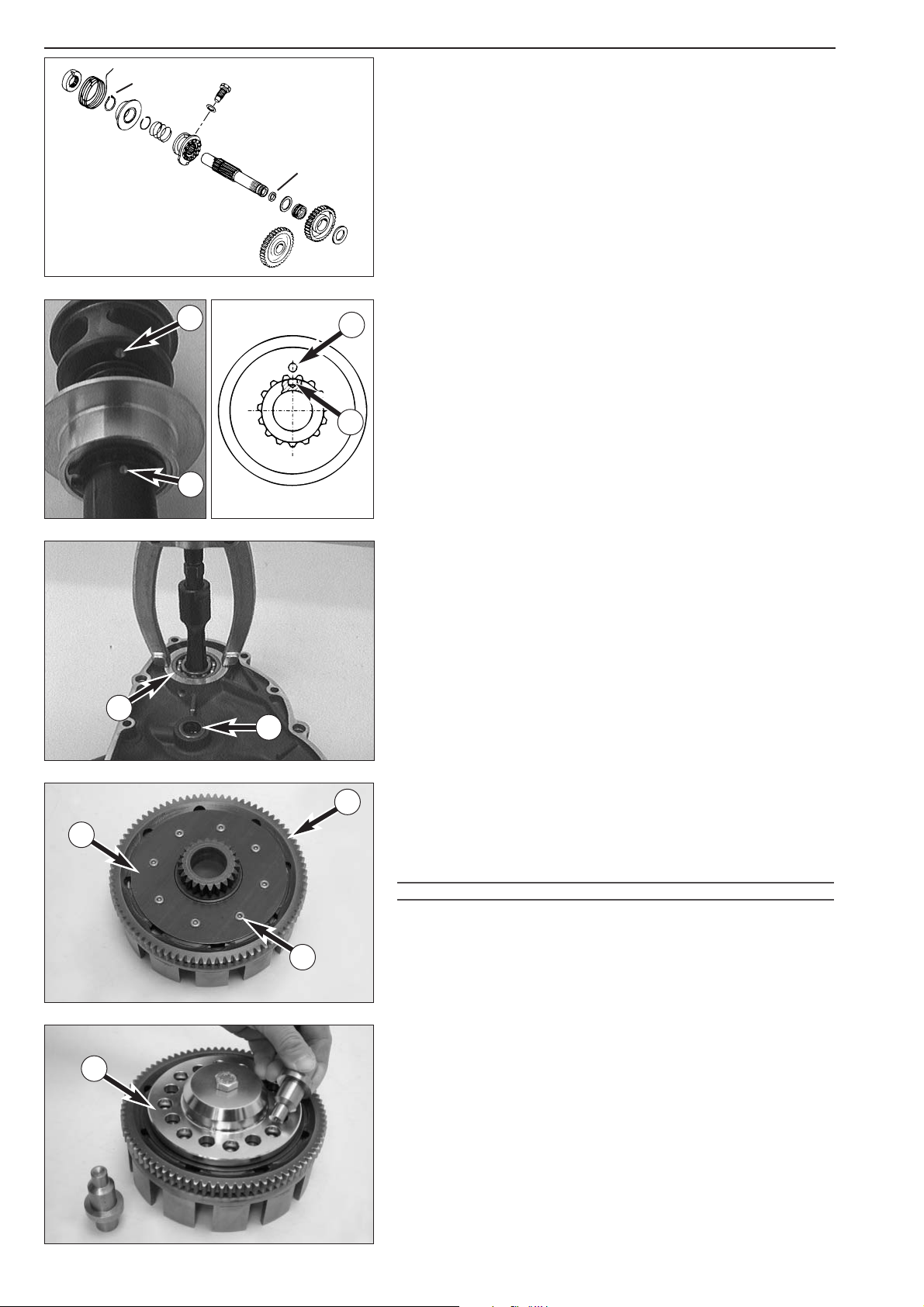
Checking the kickstarter components for wear
Starter gear 1
Check the bearing for clearance (the starter gear must be in permanent
mesh with the outer clutch hub).
Intermediate starter gear
2
Check the bearing for clearance.
Kick starter shaft
3
Check the toothing for signs of wear.
Ratchet gear
4
Check the ascending surface and the toothing for signs of wear.
Stop bolt
5
Check for signs of wear.
Replace the seal ring
6
NOTE: Due to a parts change from 2000 onwards the seal ring is
blue-green and is to be mounted with the seal lip to the outer side.
Preassembly of kickstarter shaft
– Clamp kickstarter shaft with toothed end in vice (use soft jaw-
covers).
– Mount circlip
7 in lower ring groove.
– Fit spring guide
8 with collar facing downwards and circlip 9 with
sharp edge facing upwards.
– Remove kickstarter shaft from vice and fit ratchet gear spring.
–Mount the ratchet gear
4 on the kickstarter shaft in such a way that
the markings
A and B coincide.
Clutch cover
Balancer shaft bearing bk
Use the bearing extractor tool with insert to remove the grooved ball
bearing from the bearing seat.
Insert the new bearing into the seat and ensure flush fit.
Seal ring
bl
Use a screwdriver to lever the old shaft seal ring out of the clutch cover.
Insert the new shaft seal ring and ensure flush fit.
Replacing absorbing elements of the outer clutch hub
– Drill open the clutch rivets bm in area of the retaining bracket bn and
take off the parts.
NOTE: When performing repair work always exchange all 8 absorbing
elements.
!
CAUTION
!
THE DAMPING ELEMENTS ARE WIDER THAN THE PRIMARY GEAR CROWN bo. TO
ENSURE THAT THE OUTER CLUTCH HUB AND RETAINING BRACKET ARE POSITIONED
DIRECTLY ON THE PRIMARY GEAR CROWN
, THE PARTS MUST BE HELD IN POSITION
UNDER TENSION WITH THE CLUTCH RIVETTING TOOL
C BEFORE RIVETTING.
– Apply the special tool as shown, screw together and lock the rivets
with a pointed mandrel and a round mandrel.
Locking pressure for the pointed mandrel: approx. 4000 kg
Locking pressure for the round mandrel: approx. 5000 kg
2
5
6
1
8
7
3
4
9
A
B
A
B
10
11
12
14
13
C
Page 69
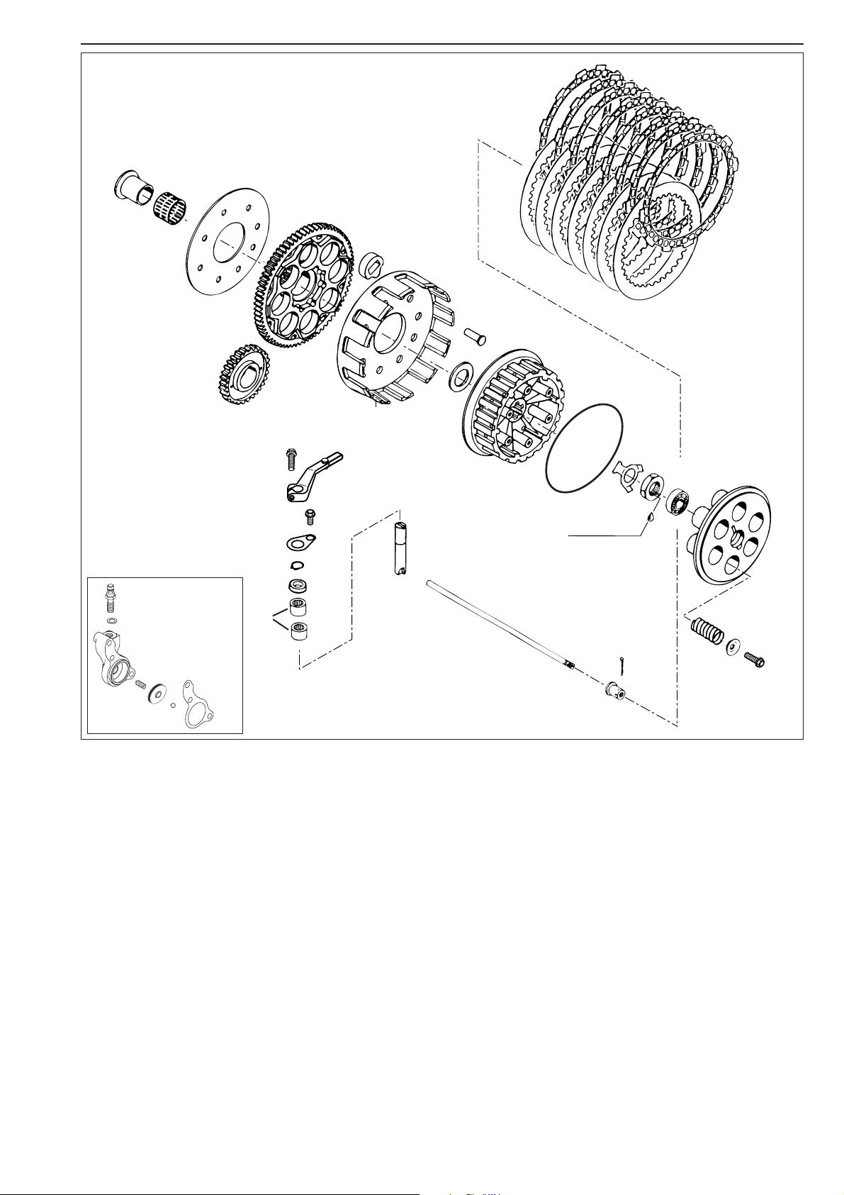
Repair manual KTM LC4 Art.-Nr. 3.206.006 -E
Checking the clutch components for wear
Thrust bearing 1 – Check for signs of wear.
Push rod
2 – Check the face side for signs of wear.
Clutch release shaft
3, sealing cup 4 and needle bearing 5 – Check for damage and signs of wear.
Clutch pressure springs
6 – Minimum length: 34.5 mm (1.36 in) (length/new spring: 37 mm (1.457 in)).
Replace all 6 springs if necessary.
Clutch discs
7 – Clutch discs must be plane.
7 steel discs ≠ 1.5 mm (0.066 in) must be free of grooves.
8 lining discs ≠ 2.7 mm (0.106 in), wear limit: 2.5 mm (0.1 in)
Inner clutch hub
8 – Check both the exterior and the interior toothing for signs of wear.
Needle bearing
9 – Check for signs of wear.
Outer clutch hub
bk – Check if all rivets bm are tight.
Absorbing elements
bl
Power transmission from the primary drive to the clutch is cushioned by rubber elements bl. These rubber elements must be
checked in the course of normal checking for signs of wear. It is recommended to check the elements while disassembling the
engine. Try to turn the outer clutch hub after removing the inner clutch hub (engine will lock). Dead travel should be impossible.
Check O-ring
bo for brittleness and cracks. If the cross section of the O-ring is oval (deformed) replace the O-ring.
5-17D
1
2
3
4
5
6
8
9
10
14
11
12
13
7
From model 2003 on
LOCTITE 243
Page 70
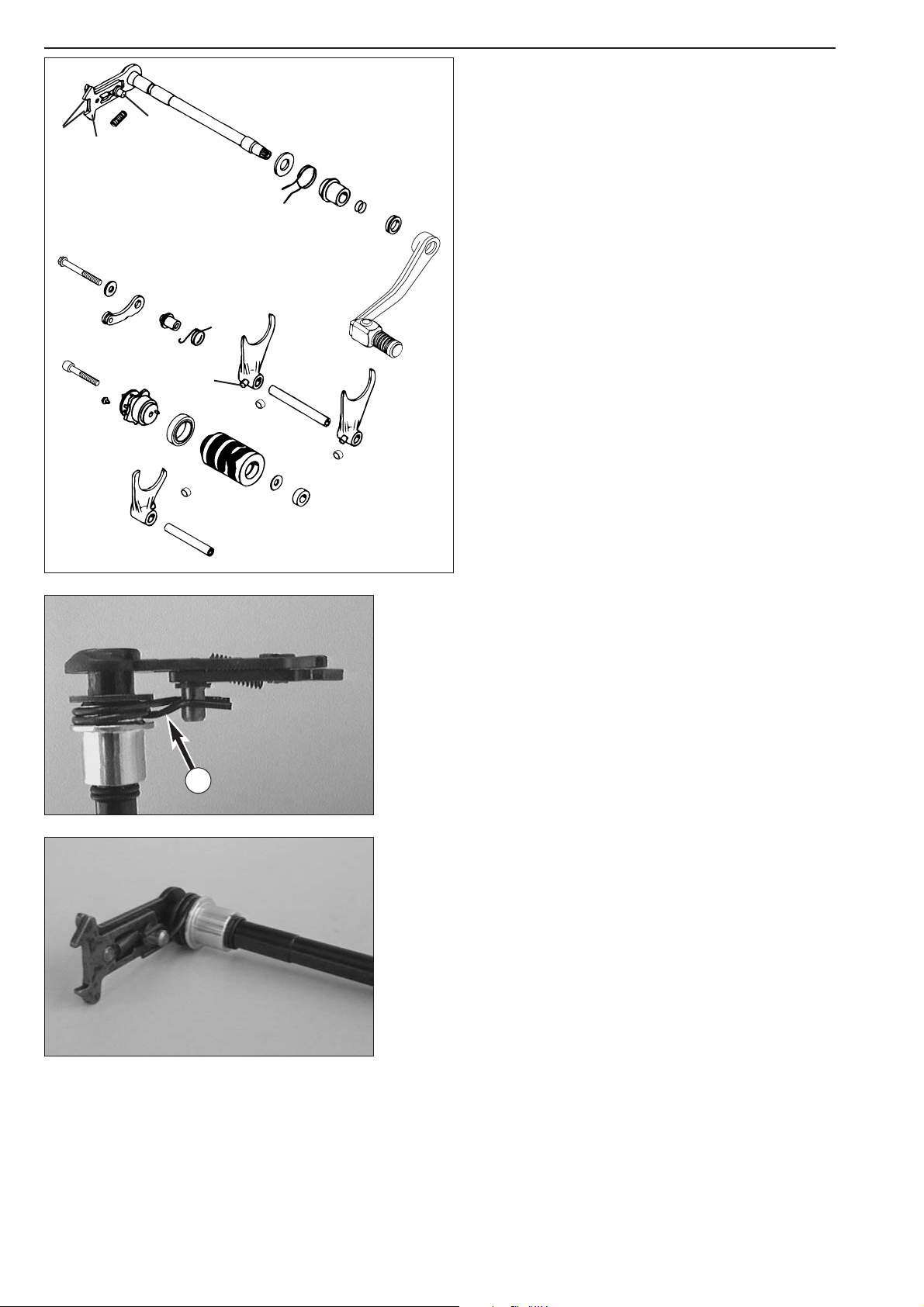
5-18D
Checking the shift mechanism components for wear
Shift forks 1
Check the fork leaf for signs of wear.
Check the shift roller driving pin
2 for signs of wear.
Shift rolls
3
Check the shift rolls for hairline cracks and pressure marks.
Additionally, make sure that the shift rolls turn easily on the
driving pins
2 of the shift forks.
Shift roller
4
Check the shift grooves for signs of wear.
Check the two grooved ball bearings of the shift roller for
wear.
Slide plate
5
Check the contact surfaces for signs of wear.
Check the return surface of the slide plate for signs of wear
(replace in the case of deep grooves).
Slide guides
Check clearance (maximum clearance between guide bolt
and slider 0.70 mm / 0.027 in.).
Guide bolt
7
Check for tight fit and signs of wear.
1
1
1
2
B
3
5
7
8
9
10
11
3
3
4
Preassembly of shift shaft
– Push steel disc 8 (14x28x2 mm) onto shift shaft.
– Mount the return spring
9, positioning the offset A on the side of
the shift quadrant.
– Mount spring sleeve
bk with shallower collar facing shift quadrant.
–Cross return spring legs and hook in shift quadrant.
–Grease and mount both O-rings
bl.
A
Page 71
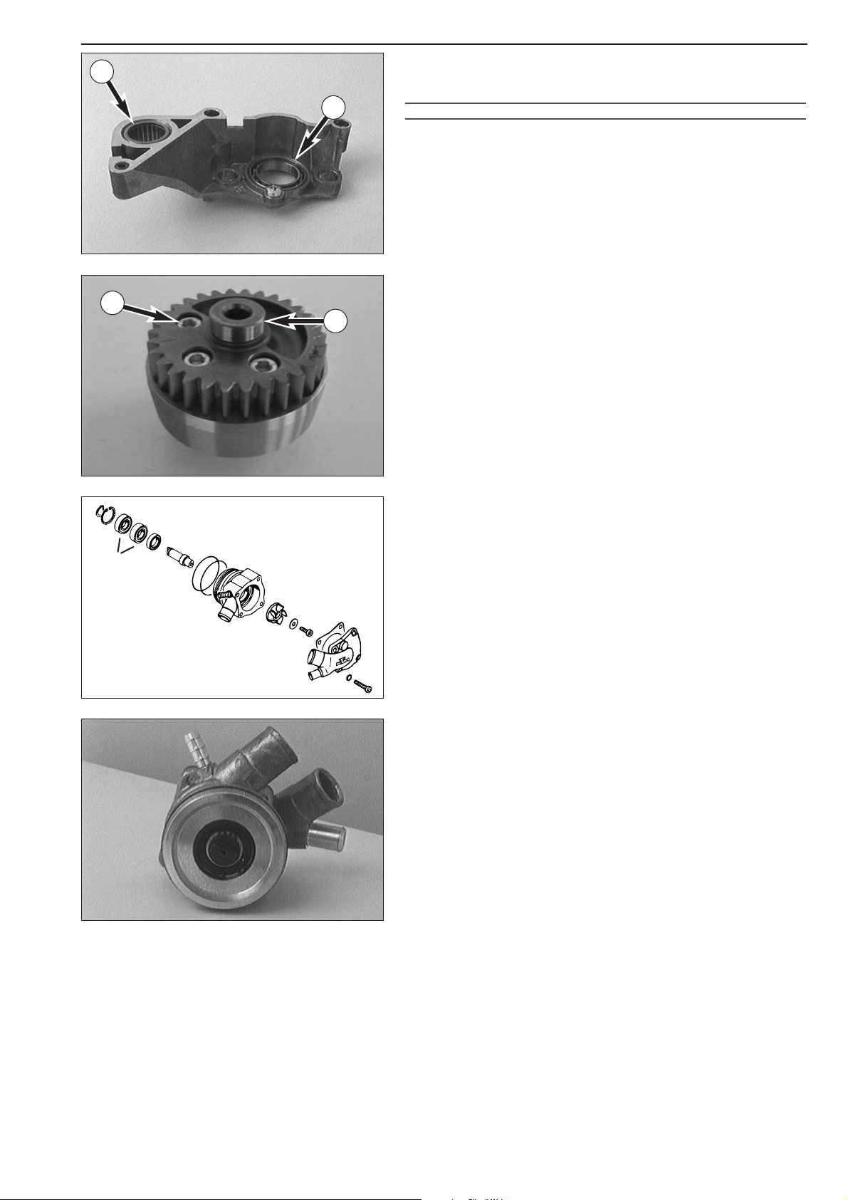
Repair manual KTM LC4 Art.-Nr. 3.206.006 -E
5-19D
Shift mechanism support
– If the grooved ball bearing 1 of the shift roller must be exchanged,
press the new grooved ball bearing all the way into the seat.
!
CAUTION
!
TO PREVENT DAMAGING OF THE SHIFT MECHANISM SUPPORT
, DO NOT APPLY
EXCESSIVE FORCE WHEN INSERTING THE GROOVED BALL BEARINGS
.
– Apply Loctite 243 to the screw and fix the bearing.
– The new needle bearing of the kickstarter shaft
2 has to be pressed
in flush.
Balancer shaft
Check bearing seat A for wear and tear.
Check three allan head bolts
3 for tight fit.
Disassembling and reassembling the water pump
Remove the water pump cover 4 together with the gasket.
– Remove circlip
5 from the water pump shaft 6 and pull shaft and
water pump wheel
7 out of the grooved ball bearings.
– If grooved ball bearings
8 are replaced, remove circlip 9 and shaft
seal ring
bk and press out bearing.
–Properly lubricate new grooved ball bearings and press in to stop
with the open sides facing each to them.
– Mount circlip
9.
– Cover new shaft seal ring with Loctite 648 and press in with the
printing facing outward.
– Lubricate water pump shaft and mount carefully so as to not
damage sealing lips of shaft seal ring and check for smooth working.
– Mount circlip
5 and water pump cover 4 with gasket.
–Finally, remove silicone from the sealing flange and mount 2 new
O-rings
bl.
5
4
6
10
11
7
9
8
1
2
A
3
Page 72

5-20D
Important note regards working on transmission
– Fix the main shaft or countershaft, respectively, in the vise (use
special vise jaws to avoid damaging of the shafts) and remove the
gear wheels.
– Clean and check all parts.
Always use new lock washers when performing repair work on the
transmission !
Check the tooth profiles of transmission shafts and sliding gears for
signs of wear.
Slide the sliding gears onto the transmission shafts and check the
toothing for easy operation.
Check the pivot points of the transmission shafts.
Mount the idler gears with the bearings on the transmission shafts and
check for clearance.
Check the needle bearings of the idler gears.
Assembling the main shaft
– Mount the main shaft in a vise with the gearwheel facing
downwards (use protective jaws).
– Mount the needle cage
1 and slide the 3rd gear 2 with the shift
dogs facing upwards.
–Mount stop disc
3 (22.7x32x1.5 mm) and the circlip 4 with the
sharp edge facing up.
–Mount 4th gear
5 with the shift groove facing down.
– Secure it with the circlip
6 with the sharp edge down and mount
the stop disc
7 (22.7x32x1.5 mm).
– Mount needle cage
8 and 5th gear 9 with the shift dogs down.
– Mount 2nd gear
bk and stop disc bl (20.2x35x1 mm).
NOTE: Check all gears for smooth operation.
1
5
6
7
8
9
10
11
2
3
4
Page 73
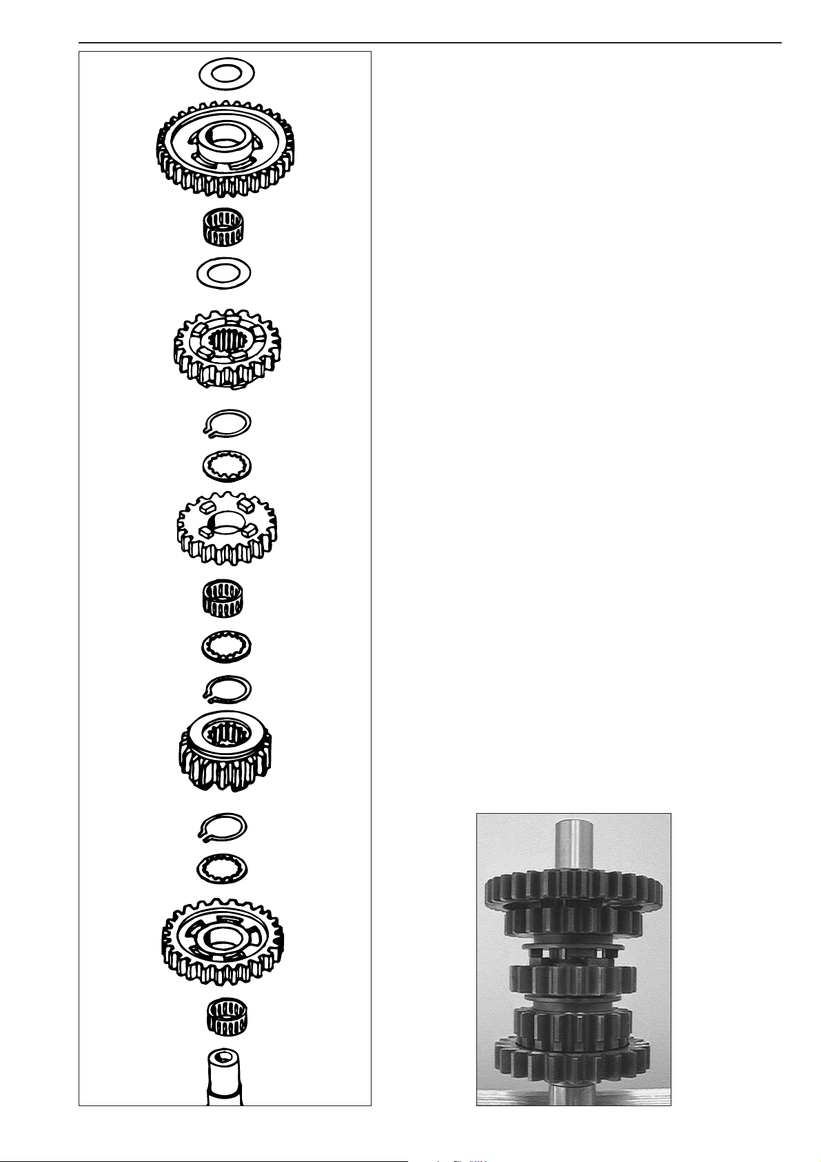
Repair manual KTM LC4 Art.-Nr. 3.206.006 -E
5-21D
Important note regards working on transmission
– Fix the main shaft or countershaft, respectively, in the vise (use
special vise jaws to avoid damaging of the shafts) and remove the
gear wheels.
– Clean and check all parts.
Always use new lock washers when performing repair work on the
transmission !
Check the tooth profiles of transmission shafts and sliding gears for
signs of wear.
Slide the sliding gears onto the transmission shafts and check the
toothing for easy operation.
Check the pivot points of the transmission shafts.
Mount the idler gears with the bearings on the transmission shafts and
check for clearance.
Check the needle bearings of the idler gears.
Assembling the counter shaft
– Mount counter shaft in vise with collar facing downwards.
– Oil and mount needle cage
1.
– Slide 2nd gear
2 over needle cage with collar facing downwards.
–Mount stop disc
3 (22.7x32.0x1.50 mm) with clearance towards
gear wheel and circlip
4 with sharp edge facing upwards.
–Mount 5th gear
5 with shift groove facing upwards.
– Fit circlip
6 with sharp edge down and stop disc 7 (22.7x32.0x1.50
mm).
– Mount needle cage
8 and fit 4th gear 9 with shift dogs facing up.
–Mount stop disc
bk (22.7x32.0x1.50 mm) and circlip bl with sharp
edge facing up.
– Fit 3rd gear
bm with shift groove down and mount stop disc
(22.2x35.0x1.50 mm)
bn.
– Mount needle cage
bo, 1st gear bp with collar facing up and fit stop
disc (20.2x35.0x1.0 mm)
bq.
NOTE: A roller bearing was installed in the 660 SMC model, thus a stop
disc is unnecessary.
Check all gears for smooth operation.
1
3
2
4
5
6
7
8
9
10
11
12
13
14
15
16
Page 74
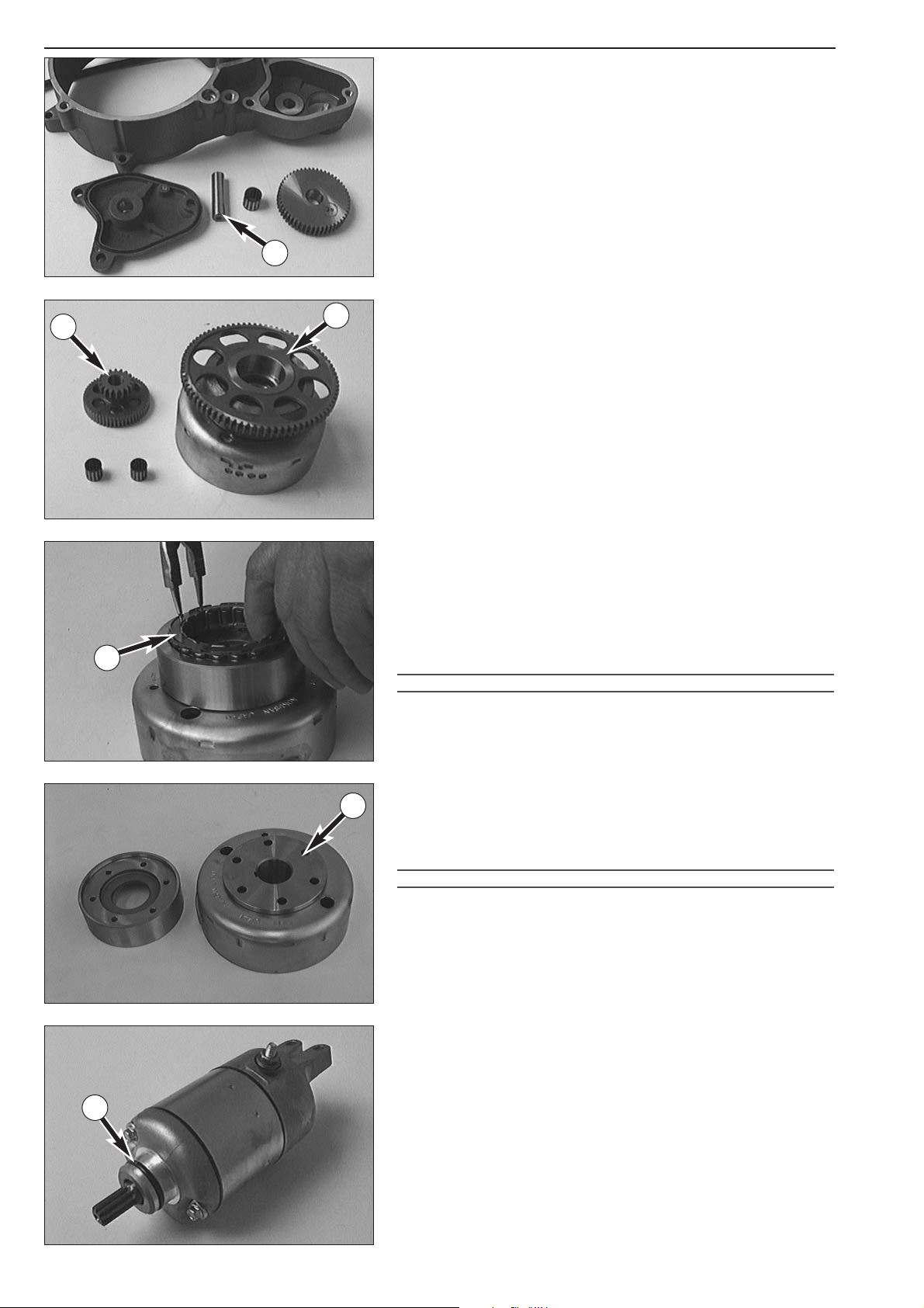
5-22D
Removing the intermediate gear
– Remove the starter cover.
– Pull out the bearing bolt
1.
– Remove the intermediate gear and the needle bearing.
– Check the parts for signs of wear.
– Insert the intermediate gear with the collar downward into the
housing for preassembly.
– Oil the needle bearing and install it with the bearing bolt.
–Do not yet replace the starter cover.
Checking the freewheel
– Insert the freewheel gear 2 into the freewheel.
– The freewheel gear must turn clockwise.
– The freewheel gear must lock without empty run if turned
anticlockwise.
– Check the reduction gear
3 and the needle bearings for signs of
wear.
– Check the needle bearing of the freewheel gear for signs of wear.
Replacing the freewheel hub
– Squeeze the spreader ring 4 with the circlip pliers and remove it
together with the freewheel.
– Check the freewheel segments for signs of wear.
– Check the freewheel hub sections at the freewheel running surface
for signs of wear.
– Heat the flywheel to a temperature of approx. 80° C (176° F) and
remove the 6 bolts.
!
CAUTION
!
MAKE SURE THAT THE FLYWHEEL IS NOT HEATED BEYOND 80° C (176° F) TO
AVOID LOOSENING OF THE MAGNETS
.
– Carefully tap the side of the freewheel hub with a plastic hammer
and take off the freewheel hub.
– Apply Loctite 648 to the flange surface
A of the flywheel and the
freewheel hub.
– Mount the freewheel hub on the flywheel.
– Apply Loctite 648 to the thread of the bolts and tighten them
crosswise (18 Nm).
!
CAUTION
!
ALWAY S USE NEW BOLTS (12.9) AND APPLY LOCTITE 648 TO THE THREADS.
– Thoroughly oil the free-wheel and insert it into the freewheel hub.
– Insert the spreader ring into the groove with a pair of circlip pliers
and make sure that it properly rests in the groove.
Electric starter motor
– The starter showed only slight signs of wear after 10.000 starting
processes, and exchanging individual parts must be considered
uneconomical. Therefore, such work is not described in the present
documentation.
– Exchange the O-ring
5 at the starter flange (incl. in the gasket set).
1
4
A
2
3
5
Page 75
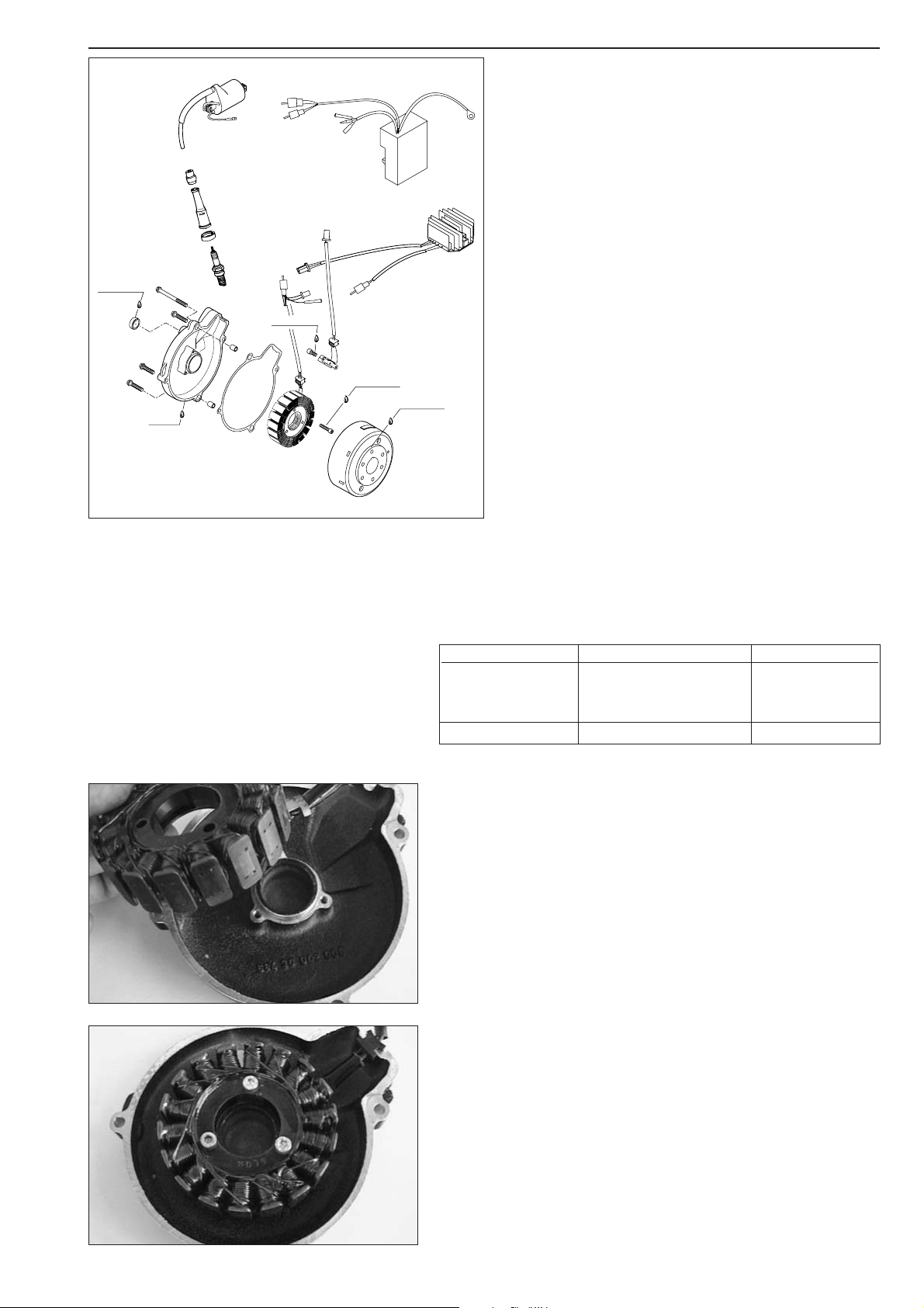
Repair manual KTM LC4 Art.-Nr. 3.206.006 -E
LOCTITE 648
5-23D
Checking the stator and the pulse generator (Kokusan 4K2)
Use an ohmmeter to perform the following measurements:
NOTE: The measuring must be performed at a temperature of 20° C.
Otherwise significant deviations must be expected.
Replace the stator and/or the pulse generator if the measured values
deviate significantly from the setpoint values or in the case of continuity
between one of the cables and ground.
Replacing the stator (Kokusan 4K2)
– Loosen the 3 bolts and remove the stator.
– Insert a new stator into the ignition cover.
– Apply Loctite 243 to 3 new bolts and tighten the bolts.
– Insert the cable guide in the opening provided for that purpose in
the ignition cover.
Ignition (Kokusan 4K2)
General information
The measurements described below will only reveal severe
problems. Coil short circuits leading to weak ignition sparks
or low generator output, respectively, can only be detected
with the help of an ignition test bench. In the case of
malfunction always check the cables and the plug and socket
connections of the ignition system first.
Make sure to select the correct measuring range when
performing measurements.
MEASUREMENT CABLE COLORS RESISTANCE
red/black – black/red
Stator yellow – black/red 0.45 – 0.56 Ω
yellow – red/black
Pulse generator white – green 80 – 120 Ω
LOCTITE 243
LOCTITE 243
LOCTITE 648
SILICON
Page 76
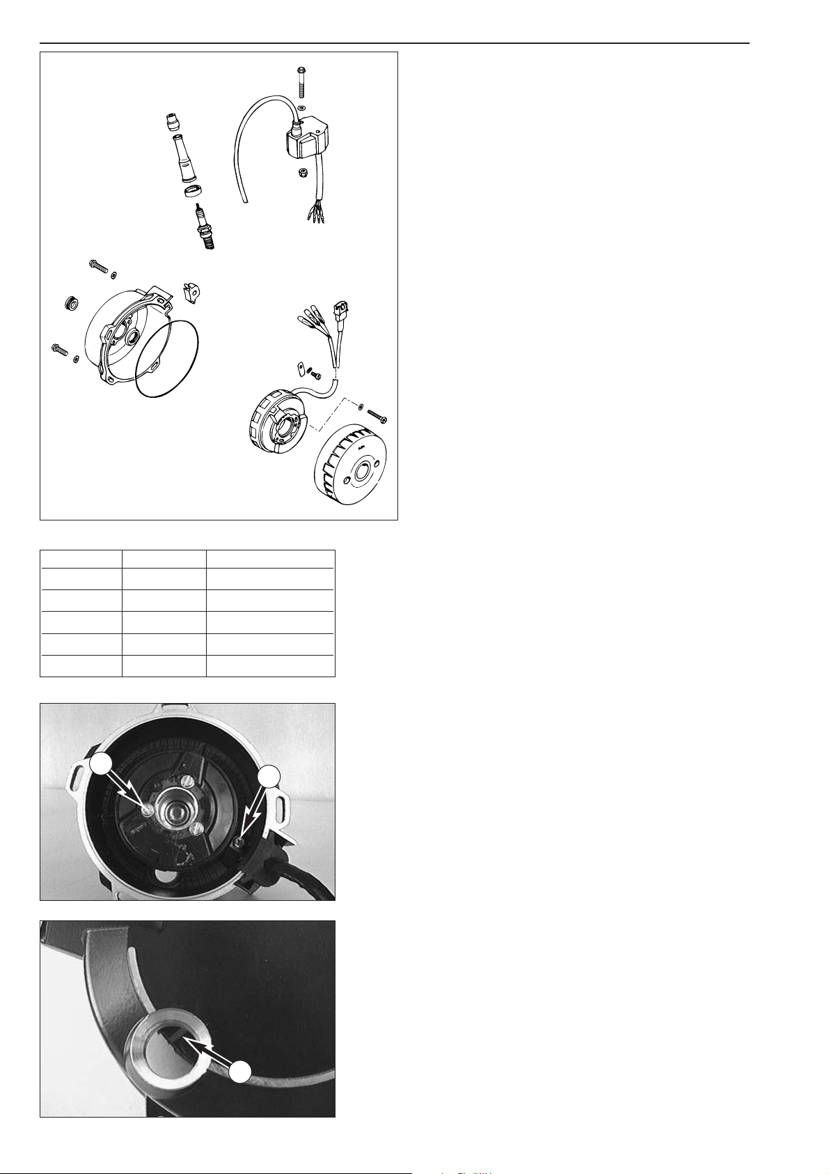
Checking the stator (SEM)
Perform the measurements indicated to the left with an ohmmeter.
NOTE: The measuring must be performed at a temperature of 20° C.
Otherwise significant deviations must be expected.
The stator must be exchanged if any of the measured values deviates
significantly from the respective nominal value or in the case of
continuity between one of the cables and ground.
Replacing the stator (SEM)
– Remove bolt 1 with retaining bracket.
– Remove the three clamp bolts
2 and lift the stator out of the
ignition cover.
– Mount the new stator in such a way that the timing mark
A is
visible in the checking hole on the rear side.
– Apply Loctite 243 to the threads of the bolts
2 and insert the bolts
without, however, tightening them yet.
– Apply Loctite 243 to the thread of bolt
1, turn the stator clockwise
all the way to the stop.
– Fix the cable strand with retaining clips and insert the rubber cable
guide into the opening provided for that purpose.
–Turn the stator until the mark becomes visible in the peephole. Then
tighten the bolts
2.
5-24D
Ignition (SEM)
General information
The measurements described below will only reveal severe
problems. Coil short circuits leading to weak ignition sparks
or low generator output, respectively, can only be detected
with the help of an ignition test bench. In the case of
malfunction always check the cables and the plug and socket
connections of the ignition system first.
Make sure to select the correct measuring range when
performing measurements.
1
2
A
+ POLE – POLE MEASURE VALUE
black red 1.7 kΩ
red black 1.7 kΩ
black green 165 Ω +/- 20 Ω
green red 1.7 kΩ
yellow yellow 1.0 Ω
Page 77
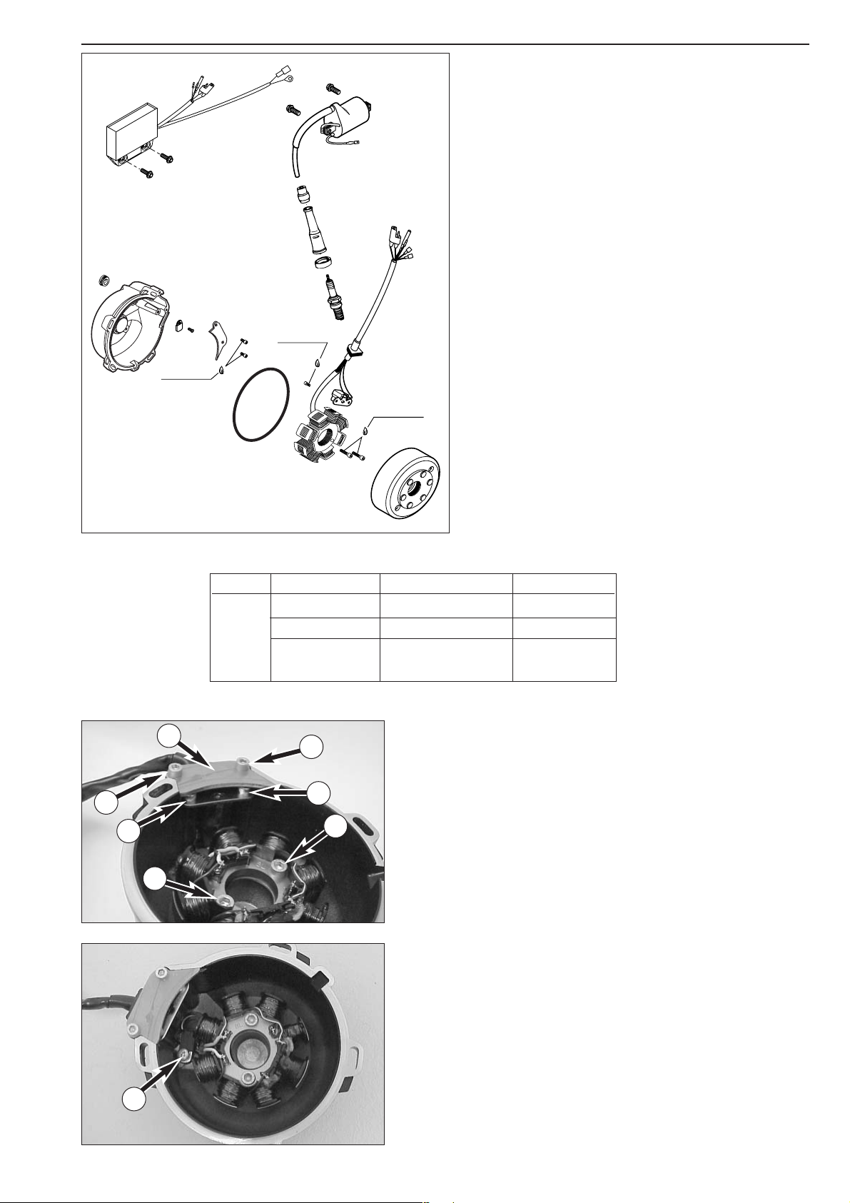
Repair manual KTM LC4 Art.-Nr. 3.206.006 -E
5-25D
Installing a new stator (Kokusan 4K-3)
– Remove the 2 bolts 1 and take the cover plate 2 out of the ignition
cover.
– Remove the 2 bolts
3 of the pulse generator and the 2 bolts 4 of
the stator.
– Undo bolt
5 and take the retaining platelet out of the ignition
cover. Take the stator and the pulse generator out of the ignition
cover.
NOTE: When reassembling the unit, degrease and apply Loctite 243 to
the threads of all bolts.
– Put the new stator into the ignition cover and fix it with the two
bolts
4.
– Position the pulse generator in the ignition cover and fix it with the
two bolts
3.
– Put the cable guide into the recess provided for this purpose and fix
the cover plate
2 with the two bolts 1.
– Position the wiring harness, taking care to avoid tension, and use the
retaining platelet and the bolt
5 to fix it in the ignition cover.
Ignition (Kokusan 4K-3)
General information
The measurements described below will only reveal severe
problems. Coil short circuits leading to weak ignition sparks
or low generator output, respectively, can only be detected
with the help of an ignition test bench. In the case of
malfunction always check the cables and the plug and socket
connections of the ignition system first.
Make sure to select the correct measuring range when
performing measurements.
Checking the stator (Kokusan 4K-3)
Use an ohmmeter to perform the following measurements.
Note: The measuring must be performed at a temperature of
20° C. Otherwise significant deviations must be expected.
Replace the stator if the measured values deviate significantly
from the setpoint values.
LOCTITE 243
1
1
2
3
3
4
4
5
Ignition
Measure Cable colours Resistance
Pulser coil red – green 100 Ω 20%
4K-3
Stator
black/red – red/white
12,7 Ω 20%
Charging coil ground – yellow 0,65 Ω 20%
white – yellow 0,16 Ω 20%
LOCTITE 243
LOCTITE 243
Page 78

Page 79

MOUNTING THE KICKSTARTER UNIT . . . . . . . . . . . . . . . . . . . . . . . . . . . .6-2
MOUNTING TRANSMISSION AND SHIFT MECHANISM . . . . . . . . . . . . . .6-2
ADJUSTMENT OF RETURN SPRING . . . . . . . . . . . . . . . . . . . . . . . . . . . . .6-4
PRETENSIONING OF THE STARTER SPRING . . . . . . . . . . . . . . . . . . . . . . .6-4
MOUNTING CRANKSHAFT . . . . . . . . . . . . . . . . . . . . . . . . . . . . . . . . . . . .6-4
ASSEMBLY OF ENGINE HOUSING . . . . . . . . . . . . . . . . . . . . . . . . . . . . . . .6-5
MOUNTING OIL FILTER . . . . . . . . . . . . . . . . . . . . . . . . . . . . . . . . . . . . . .6-6
MOUNTING THE ENGINE SPROCKET . . . . . . . . . . . . . . . . . . . . . . . . . . . .6-6
MOUNTING THE TIMING GEAR AND THE TIMING CHAIN . . . . . . . . . . . .6-7
MOUNTING THE OIL PUMPS . . . . . . . . . . . . . . . . . . . . . . . . . . . . . . . . . .6-7
MOUNTING THE BALANCER SHAFT AND THE PRIMARY PINION . . . . . . .6-8
MOUNTING THE CLUTCH . . . . . . . . . . . . . . . . . . . . . . . . . . . . . . . . . . . .6-8
MOUNTING THE CLUTCH DISCS . . . . . . . . . . . . . . . . . . . . . . . . . . . . . . .6-9
INSTALLING THE CLUTCH RELEASE SHAFT . . . . . . . . . . . . . . . . . . . . . . . .6-9
ADJUSTING THE CLUTCH RELEASE . . . . . . . . . . . . . . . . . . . . . . . . . . . .6-10
MEASURE DIMENSION „Y“ . . . . . . . . . . . . . . . . . . . . . . . . . . . . . . . . . .6-10
MOUNTING PISTON AND CYLINDER . . . . . . . . . . . . . . . . . . . . . . . . . . .6-10
MOUNTING THE CYLINDER HEAD . . . . . . . . . . . . . . . . . . . . . . . . . . . . .6-11
MOUNTING THE CAMSHAFT, TIMING MARKS . . . . . . . . . . . . . . . . . . . .6-12
MOUNTING THE WATER PUMP . . . . . . . . . . . . . . . . . . . . . . . . . . . . . . .6-13
MOUNTING THE CYLINDER HEAD TOP SECTION . . . . . . . . . . . . . . . . .6-14
MOUNTING THE AUTOMATIC TENSIONER . . . . . . . . . . . . . . . . . . . . . .6-14
AUTOMATIC DECOMPRESSION TESTING . . . . . . . . . . . . . . . . . . . . . . . .6-14
ADJUSTMENT OF VALVE CLEARANCE . . . . . . . . . . . . . . . . . . . . . . . . . .6-15
MOUNTING THE CLUTCH COVER . . . . . . . . . . . . . . . . . . . . . . . . . . . . .6-15
MOUNTING THE ELECTRIC STARTER DRIVE . . . . . . . . . . . . . . . . . . . . . .6-16
MOUNTING THE IGNITION (KOKUSAN) . . . . . . . . . . . . . . . . . . . . . . . .6-16
ADJUSTING THE PULSE GENERATOR . . . . . . . . . . . . . . . . . . . . . . . . . . .6-17
MOUNTING THE IGNITION (SEM) . . . . . . . . . . . . . . . . . . . . . . . . . . . . .6-17
ADJUSTMENT OF IGNITION POINT (SEM) . . . . . . . . . . . . . . . . . . . . . . .6-18
MOUNTING THE EPC WIRING HARNESS . . . . . . . . . . . . . . . . . . . . . . . .6-18
MOUNTING THE IGNITION (KOKUSAN 4K-3) . . . . . . . . . . . . . . . . . . . .6-19
ADJUSTMENT OF IGNITION POINT (KOKUSAN 4K-3) . . . . . . . . . . . . . .6-19
MOUNTING THE OIL HOSES . . . . . . . . . . . . . . . . . . . . . . . . . . . . . . . . .6-20
MOUNTING THE CLUTCH RELEASE LEVER . . . . . . . . . . . . . . . . . . . . . . .6-20
MOUNTING THE ELECTRIC STARTER MOTOR . . . . . . . . . . . . . . . . . . . .6-20
MOUNTING THE WATER HOSES . . . . . . . . . . . . . . . . . . . . . . . . . . . . . .6-20
POURING IN ENGINE OIL . . . . . . . . . . . . . . . . . . . . . . . . . . . . . . . . . . . .6-21
MOUNTING THE KICKSTARTER AND THE SHIFT LEVER . . . . . . . . . . . . .6-21
Repair manual KTM LC4 Art.-Nr. 3.206.006 -E
ASSEMBLING THE ENGINE
INDEX
6-1D
6
Page 80

Page 81
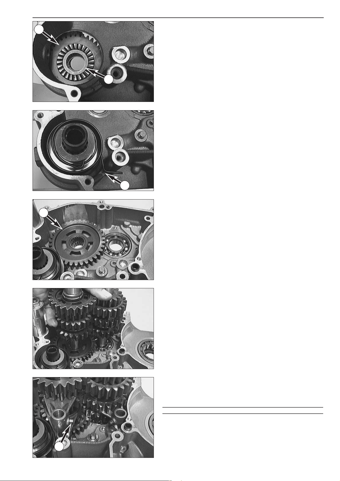
Repair manual KTM LC4 Art.-Nr. 3.206.006 -E
– Place left-hand housing half in engine work stand.
Mounting the kickstarter unit
– Insert stop disc (22.2x35x2 mm), starter gear 1, needle bearing and
stop disc
2 (22.2x30x1.5 mm) into housing.
– Insert the pre-assembled kickstarter shaft into the bearing seat,
putting it through the starter gear. Make sure that the starter spring
slips into opening
A of the housing.
Mounting transmission and shift mechanism
– Insert stop disc (20.2x35x1 mm), 1st gear wheel 3 with collar facing
down into the housing and the needle bearing into the idler gear.
NOTE: A roller bearing was installed in the 660 SMC model, thus a stop
disc is unnecessary.
– Mount transmission shafts together and slightly turn them.
–
Grease the driving pins of the shift forks and mount the shift rollers
4.
– Hook shift fork with legs of same length in the sliding gear of the
main shaft.
– Fit the other two shift forks into the gears of the counter shaft,
paying attention to the marks applied during disassembly.
!
CAUTION
!
USED SHIFT FORKS SHOULD BE MOUNTED IN THE SAME SLIDING GEAR AS BEFORE.
6-2D
1
2
A
3
4
Page 82
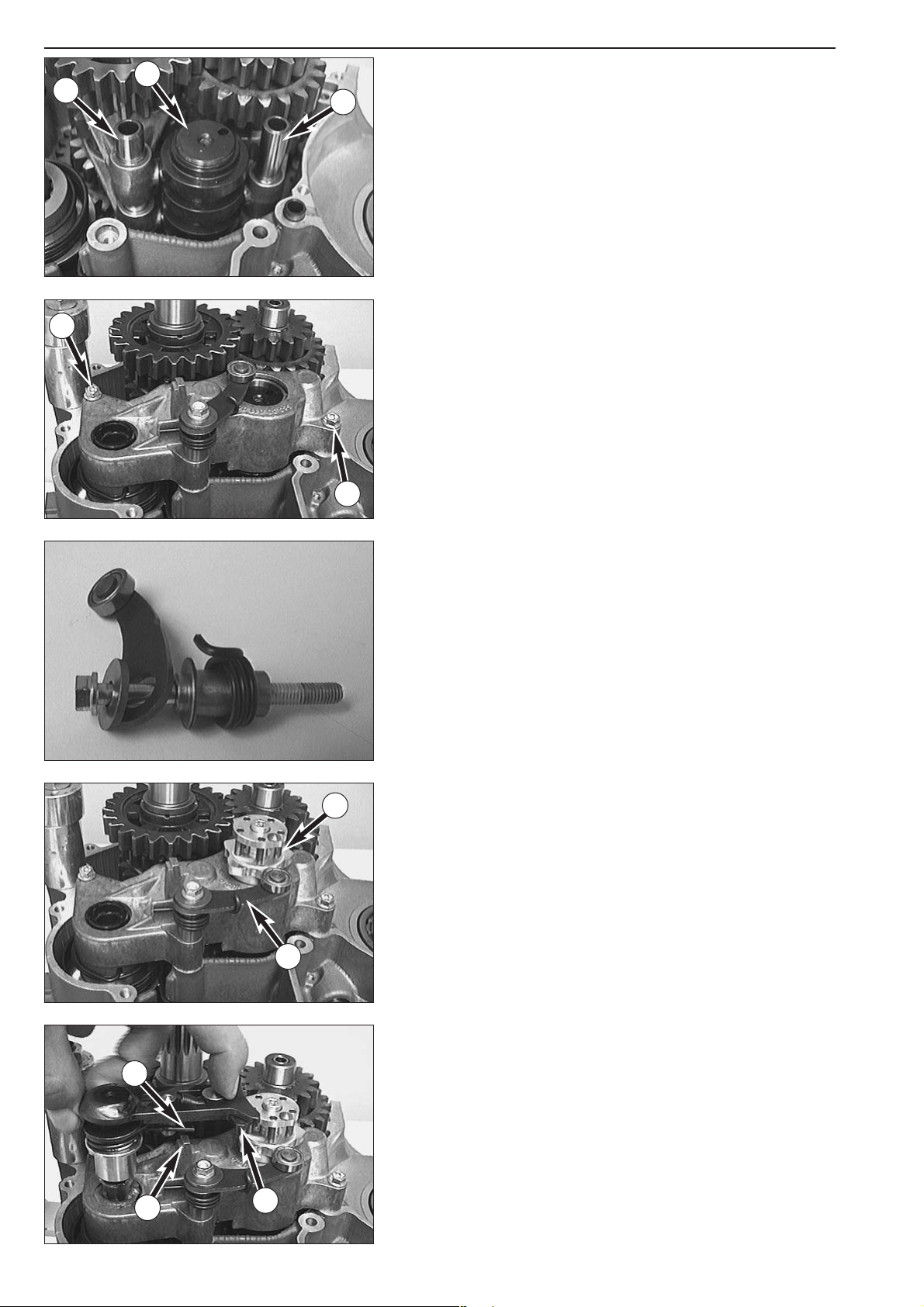
– Insert shift roller 1 into the housing with the holder for the locking
piece facing up.
– Hook the shift forks into the shift roller and mount shift rails
2 + 3.
The shorter shift rail
3 must be fitted to the main shaft.
– Before mounting the shift mechanism support, check whether the
two dowels have been fitted.
– Mount shift mechanism support, secure the two bolts
4 with Loctite
243 and tighten.
– Put the washer (6.2x18x2 mm), the locking lever, the locking spring
bushing and the locking lever spring onto the third bolt.
– Apply Loctite 243 to the thread of the bolt and mount it.
– Pull locking lever
5 away from the shift roller.
– Put the shift drum locating device
6 onto the shift roller, apply
Loctite 243 to the thread of the bolt and fix the shift drum locating
device.
– Oil the O-rings and grease the shank of the shift shaft.
– Slide preassembled shift shaft into kickstarter shaft.
– At the same time, push back the slide plate
7 and make sure that
the ends of the return spring
9 are resting against the centering cup
of the shift mechanism support
8.
6-3D
1
2
3
4
4
5
6
7
8
9
Page 83
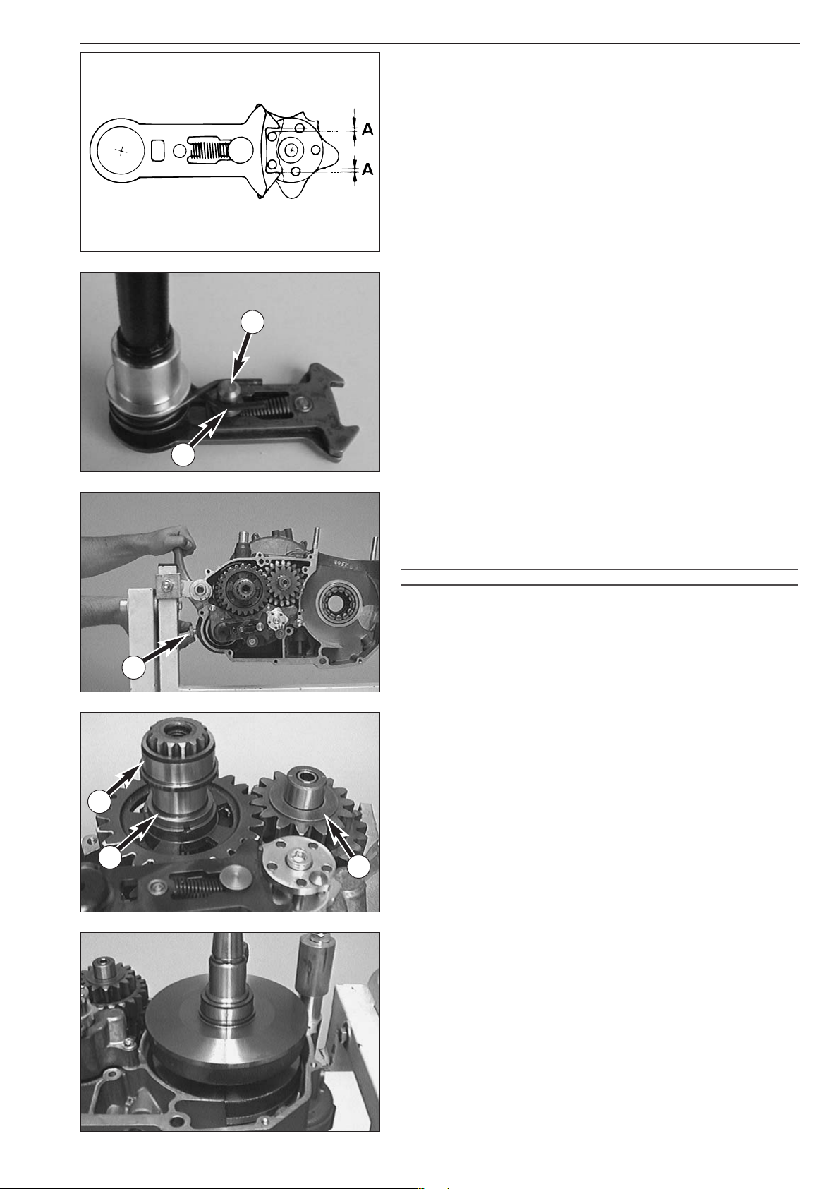
Repair manual KTM LC4 Art.-Nr. 3.206.006 -E
6-4D
Adjustment of return spring
– Engage second or third gear.
– Check free travel of slide plate and check shift pin play.
– The free travel of the slide plate is the path this component travels
until the shift roller is moved. The return spring pressure will be felt.
Proceeding from the basic position, this free travel
A should be
identical for upward and downward movement.
– If necessary, the free travel must be readjusted by adjusting the
return spring.
– For this purpose, remove the shift shaft and bend the return spring
by an appropriate amount at points
B using a pair of pliers. Refit
shift shaft. After the shifting shaft has been fitted, the return spring
must rest against shift pin
1 and against the centering cup on the
shift mechanism support.
– If necessary, bend the return spring accordingly.
Pretensioning of the starter spring
– Fit kickstarter onto kickstarter shaft, turn one revolution in starting
direction and hold in this position.
–Mount the stop bolt
2 together with a new seal ring and tighten it
manually.
!
CAUTION
!
IT MUST BE POSSIBLE TO MOUNT THE STOP BOLT WITHOUT APPLYING EXCESSIVE
FORCE
. IFITISNOT POSSIBLE TO MOUNT THE STOP BOLT MANUALLY, TURN THE
KICKSTARTER SHAFT FURTHER AGAINST THE FORCE OF THE SPRING UNTIL THE STOP
BOLT CAN BE MOUNTED
.
– Move kickstarter to stop and remove.
–Tighten stop bolt
2 with 50 Nm.
– Place O-ring
3 (22x1 mm) and inner ring 4 of roller bearing on the
counter shaft with the collar facing the gear.
–Mount stop disc
5 (20.2x35x1 mm) onto the main shaft.
Mounting crankshaft
–Grease the shaft seal ring of the crankshaft and thoroughly oil the
roller bearing of the crankshaft.
– Fit mounting sleeve onto crankshaft and place crankshaft into
bearing.
1
B
2
3
4
5
Page 84

6-5D
Assembly of engine housing
– Make sure both dowels are in place in the left housing half, and put
gasket on the sealing surface. Use a little bit of grease to hold the
gasket in place.
–Grease all shaft seal rings in the left side of the housing.
– Oil all bearings in the right side of the housing and put on the
housing half. If necessary, tap lightly with a plastic mallet and turn
transmission shafts.
– Check to make sure that the gasket is in the proper position before
final assembly.
–Grease housing bolts (threads and contact surfaces of bolts heads).
Insert bolts and assemble the housing (see sketch for bolt lengths).
– Check all the shafts for smooth operation before and after tightening
with 7-8 Nm.
– Mount case in mounting rack and check function of gear-change by
engaging all gears.
– Check crankshaft axial clearance (0.03 - 0.12 mm) (0.0012 - 0.0047
in) and fit crankshaft locking bolt.
NOTE: On Adventure-models bolts M6x35 are used instead of the two
upper bolts M6x30.
NOTE: On Adventure-models bolts M6x35 are used instead of the two
upper bolts M6x30.
SX, SXC
M6x30
M6x55
SC
LC4-E
M6x30
M6x55
M6x65
M6x95
M6x30/35
M6x30
M6x65
M6X55
640 LC4 2003 on
M6x55
M6x30
M6x55
M6x65
M6x30/35
Page 85
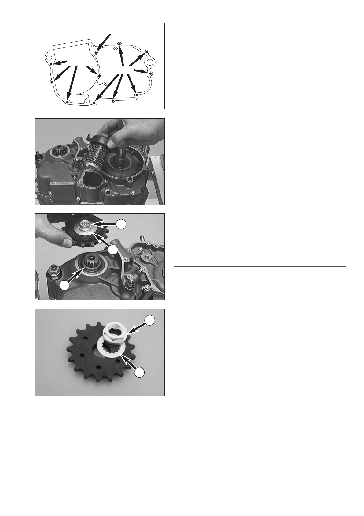
6-6D
Repair manual KTM LC4 Art.-Nr. 3.206.006 -E
1
2
3
SXC/SMC 2003 on
M6x55
M6x30
M6x65
4
5
Mounting oil filter
– Fit oil filter with rubber gasket onto the connection in the oil filter
cover.
– Fit a new O-ring into the oil filter cover groove or use new gasket
and fix the oil filter cover with the 3 bolts, tighten bolts with 5 Nm.
Mounting the engine sprocket
– Lubricate O-ring (25x2 mm) with oil and slide over countershaft.
– Slide distance bushing
1 in position so that O-ring is in correct
position.
NOTE: The distance bushing for Duke and Supermoto-models is 2mm
thicker.
!
CAUTION
!
DO NOT REVERSE DUST LIP OF THE SHAFT SEAL
.
– Fit the engine sprocket with the collar facing the housing.
NOTE: For Duke and Supermoto-models an additional 2 mm washer is
used.
– Apply Loctite 243 to thread of sprocket bolt.
–Mount spring retainer
2 and sprocket bolt 3.
– Apply counterpressure with the sprocket holding spanner and tighten
sprocket bolt.
NOTE: Tighten bolts with quality 8.8 to 40 Nm, bolts with quality 10.9
to 60 Nm.
NOTE (from model 2003 on):
A collar nut
4 and a lock washer 5 are installed in some of the models
instead of a collar screw.
Tightening torque off the collar nut: 60 Nm
Page 86
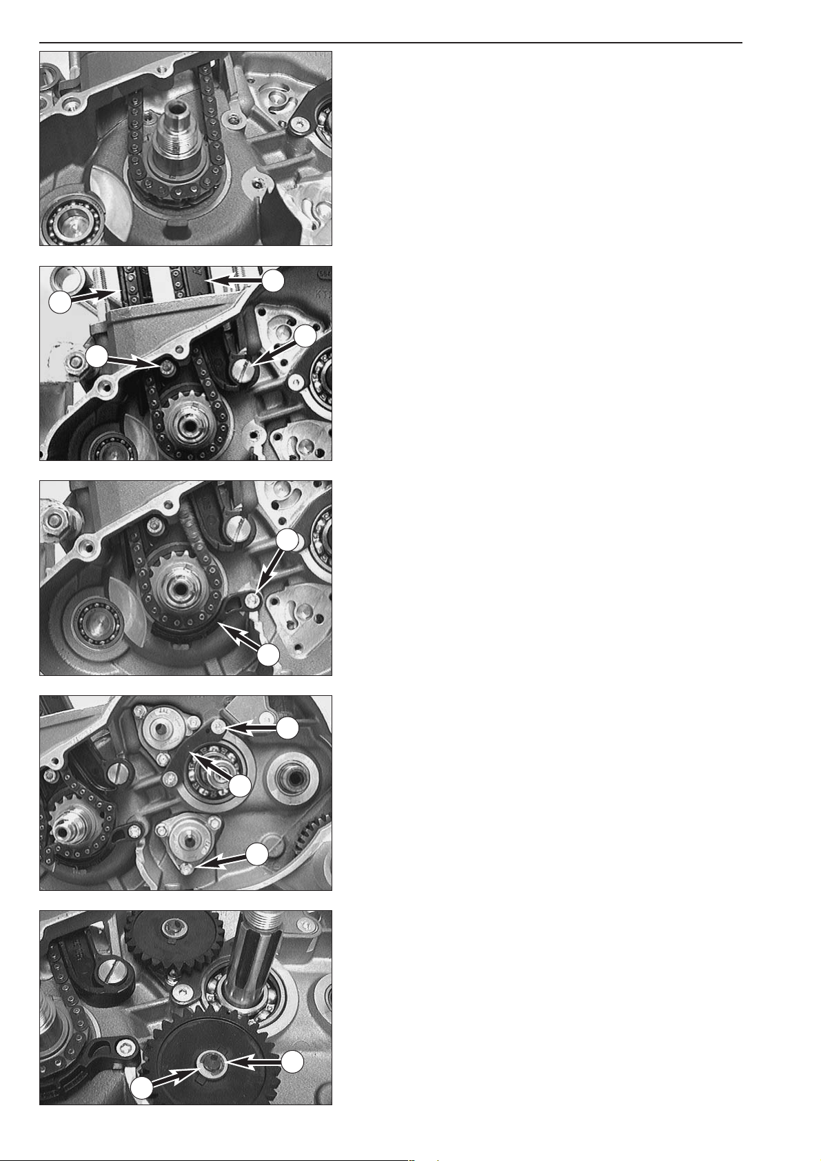
6-7D
Mount the timing gear and the timing chain
– Insert woodruff key for timing gear into crankshaft and fit timing
gear onto crankshaft with high collar towards housing.
– Fit timing chain onto timing gear and draw up through chain tunnel.
– Insert the timing chain guide
1, apply Loctite 243 to the Allen head
bolt
2 and mount.
– Apply Loctite 243 to the thread of the flat-head screw
4.
– Fasten timing chain tensioner
3 with flat head screw.
– Check timing chain tensioner for smooth operation.
– Insert the safety device 5, apply Loctite 243 to the Allen head bolt
6 and mount.
Mounting the oil pumps
– Clean the sealing surfaces and install the oil pumps in the engine
housing (
A M6x25!)
– Degrease the threads and use Loctite 243 to secure the bolts in their
position.
– Degrease the threads of both bolts
7, apply Loctite 243 and mount
the retaining bracket
8.
– Put the stop discs (8.1x15x0.5 mm) onto the oil pump shafts.
– Insert the bearing needles into the oil pump shafts and slide on the
oil pump gears (high collars must face the casing; the small oil pump
gear must face the upper oil pump).
NOTE: From model 2002 onwards both oil pumps are fitted with the
same size of oil pump gear.
– Put on the upper stop discs
9 (8.1x15x0.5 mm) and mount the
locking discs
bk.
1
2
3
4
5
6
7
8
9
10
A
Page 87

6-8D
Repair manual KTM LC4 Art.-Nr. 3.206.006 -E
Mounting the balancer shaft and the primary pinion
– Fit balancer shaft in the bearing.
–Mount woodruff key in crankshaft and place primary pinion on the
crankshaft. When doing so, adjust the teeth of the primary pinion
and the balancer shaft in such a way that the markings
A and B
coincide.
– Apply Loctite 243 to the crankshaft thread.
– Mount spring ring and hexagon nut and tighten hexagon nut to 170
Nm.
!
CAUTION
!
IF THE BALANCER SHAFT IS NOT INSTALLED ALSO REMOVE BOTH GROOVED BALL
BEARINGS
(IN THE CLUTCH COVER AND IN THE ENGINE HOUSING). OTHERWISE THE
GROOVED BALL BEARINGS WOULD DROP OUT OF THE BEARING SEATS AND CAUSE
ENGINE DAMAGE AS SOON AS THE ENGINE HEATS UP
.
Mounting the clutch
– Fit kickstarter intermediate gear 1 onto counter shaft with clearance
space towards housing.
– Slide the inner ring and the needle bearing
2 onto the main shaft.
– Fit outer clutch hub and outer stop disc
3 (22.2x35x3 mm).
– Degrease the thread of the main shaft.
– Place inner clutch hub and a new safety plate on the main shaft.
– Coat the thread of the main shaft with Loctite 243 and mount
hexagon nut.
– Fit clutch holder and tighten hexagon nut to 100 Nm (60 ft.lb.).
– Remove clutch holder.
– Check clutch hub and main shaft for smooth operation and axial
clearance.
– Secure outer clutch hub hexagon nut by bending the safety plate up
into place.
A
B
1
2
3
Page 88

6-9D
Mounting the clutch discs
– Thoroughly oil the O-ring 1 and put it onto the inner clutch hub.
– Oil the lining disc
2 (internal diameter: 127 mm) and mount it,
making sure that the disc encircles the O-ring (see illustration).
– Thoroughly oil all clutch discs before mounting.
– Alternately mount 1 steel disc and one lining disc.
NOTE: The last disc must be a lining disc.
!
CAUTION
!
MOUNT ALL STEEL DISKS WITH THE SHARP EDGE FACING DOWNWARD
.
–Grease the end of the push rod with Molykote grease and fit the
pressure cap together with the push rod.
– When mounting the pressure cap make sure that bore
A in the
pressure cap and the pin
B of the inner clutch hub coincide.
– Place the springs in the pressure cap and fit the HH srews with spring
retainers.
– Secure carefully to 6 Nm in a diagonal pattern, to avoid any damage
to the inner clutch hub thread.
NOTE:
– Use offset instead of flat spring retainers for 640 ccm engines.
–From model 2000 onwards spring retainers 6,5x20x2 replaced spring
retainers 6,2x20x3,2, these can be used for all models with 540, 620
and 640 engines.
Installing the clutch release shaft
– Oil needle bushings in engine housing.
– Insert the grooved ring
3 into the housing with the open side up.
– Check for the right position of the circlip
4 on the clutch release
shaft.
– Slide the release shaft into the housing until it lies on the clutch push
rod.
1
2
A
B
3
4
Page 89

6-10D
Repair manual KTM LC4 Art.-Nr. 3.206.006 -E
–Turn the release shaft clockwise until it glides a bit further into the
housing. The push rod now sits on the release shaft.
– Apply Loctite 243 to the bolt (s).
– Fasten the retaining bracket for the clutch release
1 with bolt(s).
Adjusting the clutch release
–Turn the clutch release shaft clockwise to stop.
– The slot on the front side of the release shaft should now be parallel
to the sealing surface of the housing (see ill.).
–To adjust the clutch release remove pin
2 and turn the push rod 3
with a screwdriver until the desired setting is achieved.
– Once you have completed the adjustment, the push rod is to be
secured with a pin.
!
CAUTION
!
TO MAKE SURE THAT THE CLUTCH DISENGAGES PERFECTLY
, THE CLUTCH RELEASE
MUST BE PROPERLY ADJUSTED
.
Measure the dimension „Y" (from model 2003 on)
NOTE: The dimension „Y" must be adjusted to make sure the clutch
release operates correctly.
The dimension „Y" is the distance between the sealing area of the
clutch slave cylinder and the pushrod.
– Oil the pushrod and insert in the main shaft all the way in to the
stop.
– Measure the distance between the mounting face (without the
gasket) of the clutch slave cylinder to the pushrod using a depth
gauge.
–To adjust, remove the splint
2 and turn the pushrod 3 with a
screwdriver.
– After making the adjustment, lock the pushrod with the splint again.
Dimension „Y" = 2.75 mm
Mounting piston and cylinder
– Lubricate the piston pin eye in the connecting rod and the piston pin
with oil.
– Mount piston and secure piston pin with 2 new wire circlips.
!
CAUTION
!
T
HE ARROW ON THE PISTON HEAD MUST POINT IN THE DIRECTION OF TRAVEL.
MOUNT WIRE CIRCLIPS IN „6 O’CLOCK” OR „12 O’CLOCK” POSITION (SEE ILL.).
1
PPAARRAALLLLEELL
2
3
DIMENSION „Y“
Sealing surface of the clutch
slave cylinder
push
rod
12 o’clock-pos.
6 o’clock-pos.
Page 90
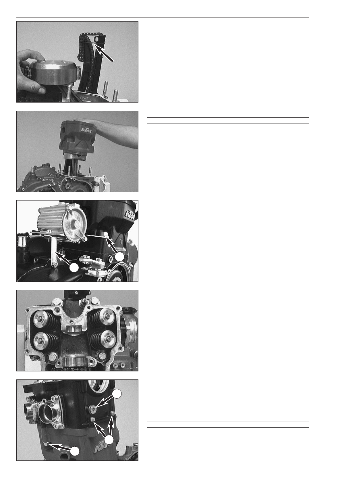
6-11D
– Cut off the section of the housing gasket protruding around the
cylinder flange and mount 2 dowels.
– Apply sealing compound to the sections near the chain tunnel and
mount the cylinder base gasket.
NOTE:
–To facilitate the installation of the cylinder it is recommended to
place a rubber band (see illustration) around the timing chain guide
and the timing chain tensioner.
– Oil the piston, adjust the piston rings (piston rings must be turned
120 ° against each other) and mount the piston mounting ring.
– Only for 640 LC4 engines a black cylinder base gasket (0,7 mm
thickness) is used, the other LC4 engines need the green gasket
(0,5mm thickness).
– Slide the cylinder over the piston and remove the mounting ring.
!
CAUTION
!
APPLY PARTICULAR CARE WHEN MOUNTING THE CYLINDER
! T
HE OIL SCRAPER RING
IS EXTREMELY FRAGILE
.
– Hook in the preassembled microfilter with the holding device onto
the rear studs and mount the collar nuts
1 at the cylinder base.
–Tighten collar nuts with 40 Nm (30 ft.lb.) crosswise.
– Then mount the bracket
2 and attach the microfilter.
NOTE: The upper edge of the piston is higher than the upper edge of
the cylinder when the cylinder is screwed down.
Mounting the cylinder head
– Check both dowels within the cylinder for proper fit.
– Mount cylinder head gasket and fit cylinder head.
–Oil the 4 bolt (threads and contact surfaces of bolt head) and then
mount with new copper seal rings.
–Tighten collar bolts crosswise in three rounds up to the prescribed
torque of 50 Nm. During the first round only tighten until a slight
resistance is felt.
–Mount M8 collar nuts
3 on the front and rear side of cylinder and
tighten.
– Mount and tighten bolts
4.
– Put a new seal ring on the chain guide bolt
5 and degrease the
thread.
– Apply Loctite 243 to the thread of the chain guide bolt, mount and
tighten it (30 Nm).
!
CAUTION
!
BEFORE MOUNTING THE CHAIN GUIDE BOLT MAKE SURE THAT THE OPENING OF THE
TIMING CHAIN GUIDE IS VISIBLE THROUGH THE THREADED HOLE
. IF THIS IS THE CASE
THE CHAIN GUIDE BOLT CAN EASILY BE MOUNTED WITHOUT EXERTING EXCESSIVE
FORCE
.
1
2
3
4
5
Page 91
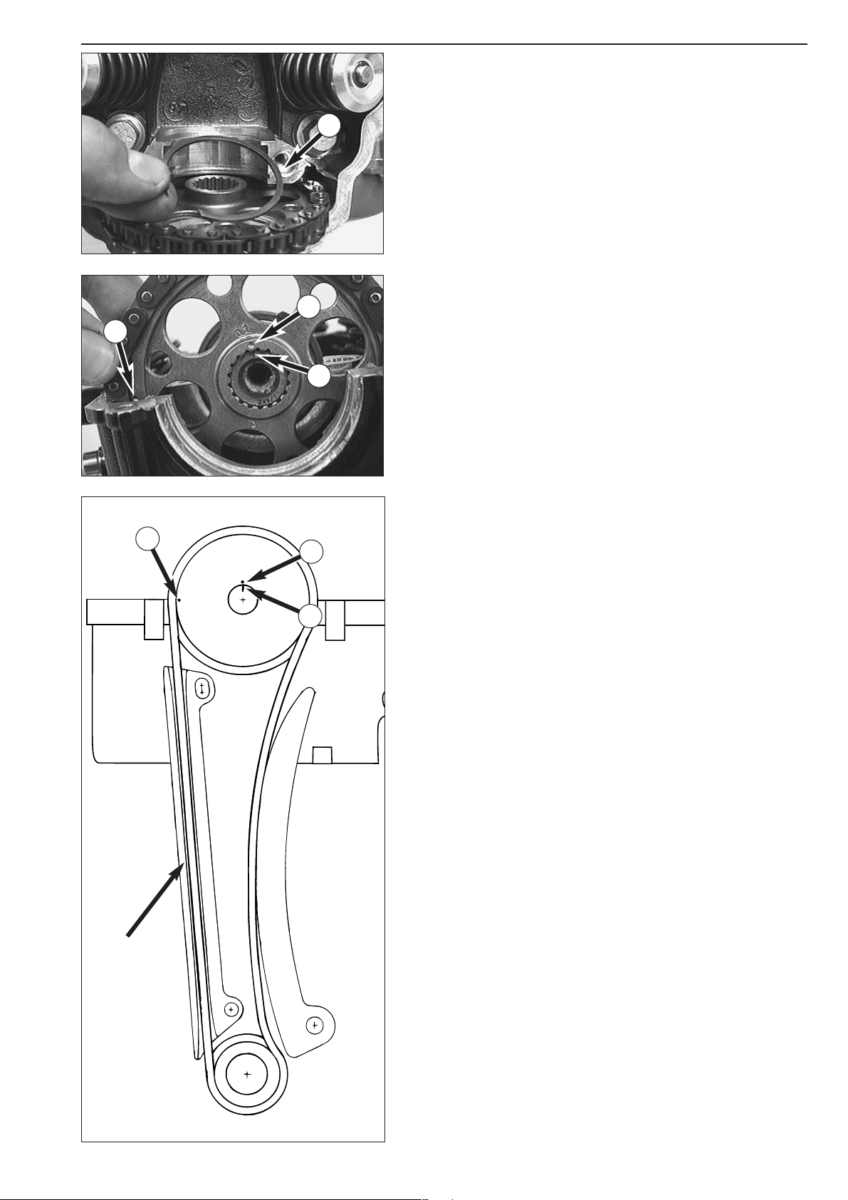
6-12D
Repair manual KTM LC4 Art.-Nr. 3.206.006 -E
Mounting the camshaft, timing marks
– Fit the camshaft gear into the timing chain so that mark A (a point)
is aligned with the top surface of the cylinder head when the timing
chain strand tensioned.
–Tilt engine to one side and place circlip
1 on camshaft gear.
– Slide grooved ball bearing flush onto the preassembled camshaft and
fit the camshaft into the camshaft gear so that the mark
B and mark
C are aligned.
A
B
C
tensioned
A
B
C
1
Page 92
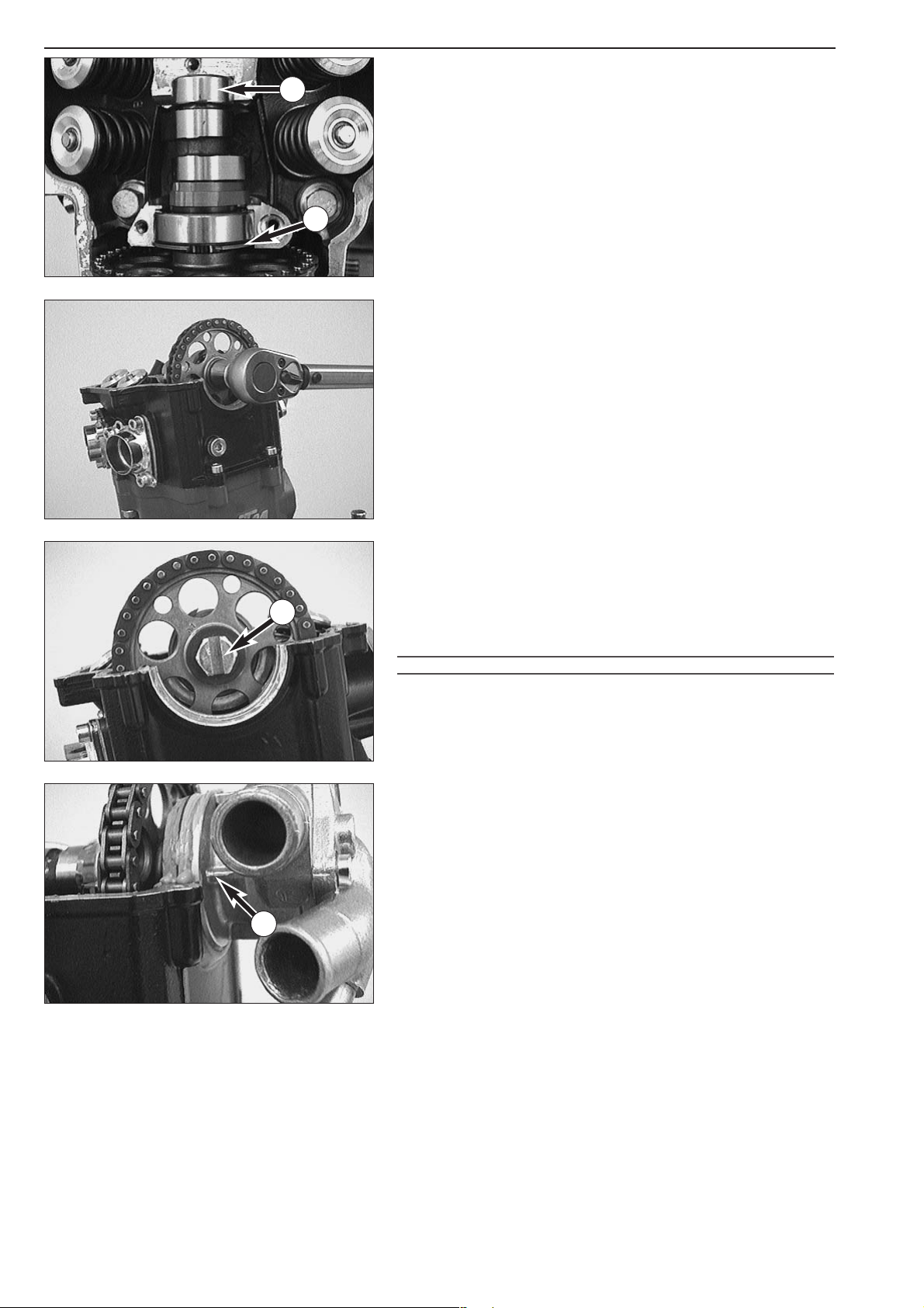
6-13D
– Lubricate the needle bushing 1 with oil and slide it onto the
camshaft.
– Mount camshaft together with bearing and circlip
2 into cylinder
head.
– Degrease the threads in the camshaft and the driving bolt and apply
Loctite 243.
– Mount the driving bolt together with the lock washer and the
washer (10x28x3 mm) and tighten (35 Nm/25 ft.lb).
Mounting the water pump
– Loosen crankshaft locking bolt and turn crankshaft until groove 3 is
at a position vertical to the sealing surface for the cylinder head top
section.
– Coat O-ring of water pump with sealing compound (Three-Bond)
and carefully mount the water pump. The flat part of the water
pump shaft must be introduced into the groove of the HH bolt.
!
CAUTION
!
THE MARKING 4 LOCATED ON THE HOUSING OF THE WATER PUMP MUST BE FLUSH
TO THE SEAL SURFACE
.
1
2
3
4
Page 93

6-14D
Repair manual KTM LC4 Art.-Nr. 3.206.006 -E
Mounting the cylinder head top section
– Clean the sealing area of the cylinder head top section and apply a
thin layer of sealing compound.
– Fit dowel in the area of the spark plug.
– Carefully position cylinder head top section (do not jam with water
pump) and mount bolts.
!
CAUTION
!
COPPER SEAL RINGS MUST BE FITTED TO THE
5 ALLEN HEAD BOLTS
1, 2 AND 3.
– Tighten bolts 1 and 2 to 8 Nm diagonally.
– Tighten bolts 2 to 15 Nm.
– Tighten all other bolts of the cylinder head top section with 8 Nm.
Mounting the automatic tensioner
– Fit preassembled automatic tensioner with gasket into the cylinder.
– Mount the clamp
4 and two bolts with copper seal rings.
!
CAUTION
!
IF THE RATCHETING PAWL IS NOT ENGAGED INTO THE FIRST NOTCH THIS WILL CAUSE
EXCESSIVE TENSION OF THE CHAIN
.
– Fit pressure spring and plug
5 with gasket and tighten with 20 Nm.
Automatic decompression testing
– Rotate the crankshaft in the usual direction of rotation (i.e. forward).
After every other rotation, the decompression cam must be clearly
heard to click as it disengages.
NOTE: If turning of the engine does not produce a click of the
decompression cam, first of all check the tightening torque of the
driving bolt (camshaft gear).
1
1
3
4
2
2
5
Page 94
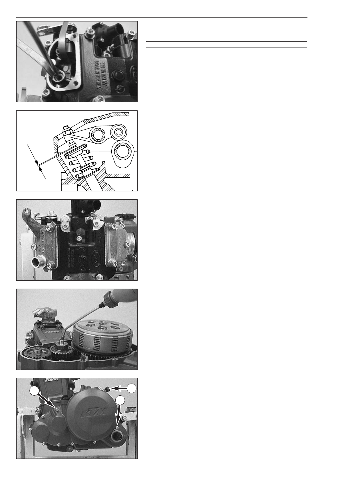
6-15D
Adjustment of valve clearance
– Adjust piston to ignition top dead center (check marks of flywheel)
and screw crankshaft locking bolt back in.
!
CAUTION
!
IF THE PISTON IS NOT IN IGNITION
TDC, VA LVES ARE OPENED AND A CORRECT
ADJUSTMENT IS NOT POSSIBLE
- IN THAT CASE CRANKSHAFT MUST BE MOVED A FULL
TURN
.
–Valve clearance
A is measured at cold engine between valve stem
and adjusting screw.
VALVE CLEARANCE 400 : INTAKE 0.20 mm / EXHAUST 0.20 mm
VALVE CLEARANCE 540 : INTAKE 0.15 mm / EXHAUST 0.15 mm
VALVE CLEARANCE 620 : INTAKE 0.15 mm / EXHAUST 0.15 mm
VALVE CLEARANCE 625 : INTAKE 0.15 mm / EXHAUST 0.15 mm
VALVE CLEARANCE 640 : INTAKE 0.15 mm / EXHAUST 0.15 mm
VALVE CLEARANCE 660 : INTAKE 0.15 mm / EXHAUST 0.15 mm
–Tighten counternuts with 20 Nm.
– Remove the crankshaft locking bolt.
– Mount both valve covers with new gaskets and bolts with copper
seal rings.
–Tighten bolts with 8 Nm.
– Insert and tighten spark plug with 20 Nm.
Mounting the clutch cover
– Pour approx. 30 ml of oil into the crankshaft journal hole.
– Make sure that the two dowels are mounted.
– Fit new gasket and fix with dabs of grease.
– Apply grease to the shaft seal ring in the clutch cover and mount
clutch cover.
– Fit bolts and bump rubber
1 for kickstarter.
NOTE: Bolts
2 must each be provided with a copper seal ring.
–Tighten bolts with 8 Nm.
1
2
2
A
Page 95

6-16D
Repair manual KTM LC4 Art.-Nr. 3.206.006 -E
Mounting the electric starter drive
– Insert the woodruff key into the crankshaft.
– Slide 2 needle bearings
1 onto the bearing pin of the reduction gear.
– Slide the needle bearing 2 onto the crankshaft.
– Oil the needle bearings.
– Mount the freewheel gear
3 and the reduction gear 4.
Mounting the ignition (Kokusan 4K-2)
– Degrease the cones of flywheel and crankshaft.
– Thoroughly oil the freewheel and mount the flywheel.
NOTE: Turn the reduction gear for easier mounting of the flywheel.
–Mount disk with the nut.
– Use the holding tool
5 to hold the flywheel and tighten the
hexagon nut with 150 Nm.
!
CAUTION
!
TOAVOID DISTORTION OF THE CRANK WEB, NEVER MOUNT THE CRANKSHAFT
LOCKING BOLT TO TIGHTEN THE HEXAGON NUT OF THE FLYWHEEL
.
– Insert 2 dowels into the housing.
– Apply silicone to both sealing surfaces and mount a new gasket.
– Mount the preassembled starter flange and use 4 bolts to fasten the
starter flange.
1
2
3
4
4
5
Page 96
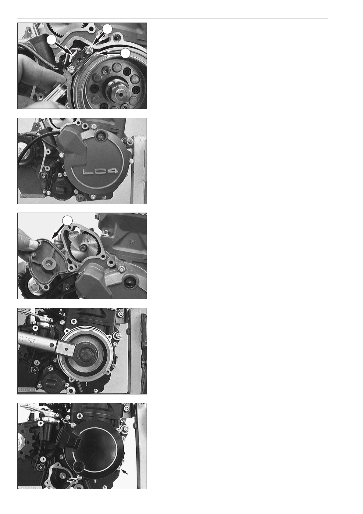
6-17D
Adjusting the pulse generator
–Turn the flywheel until the elevated section of the flywheel 1
coincides with the pulse generator 2.
– Use a feeler gauge to measure the distance between the pulse
generator and the flywheel.
Setpoint value: 0.75 mm (0.03 in) +/- 0.2 mm (0.008 in)
– If necessary undo the two bolts
3 and adjust the distance by
moving the pulse generator. When mounting the two bolts secure
them with Loctite 243.
– Insert 2 dowels.
– Apply silicone to both sealing surfaces and mount a new gasket.
– Mount ignition cover and tighten all bolts.
– Insert a new O-ring
4 into the groove of the starter cover and
fasten the starter cover with 3 bolts.
Mounting the ignition (SEM)
– Block crankshaft with crankshaft locking bolt.
– Place woodruff key in crankshaft.
– Clean cones of crankshaft and flywheel and mount flywheel.
– Fit spring washer and collar nut.
–Tighten collar nut to 60 Nm.
– Place the O-ring into the groove of the engine housing.
– Fit preassembled ignition cover and mount the 4 bolts but do not
tighten.
1
2
3
4
Page 97
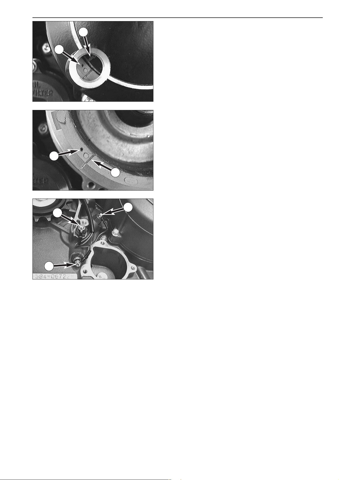
6-18D
Repair manual KTM LC4 Art.-Nr. 3.206.006 -E
Adjustment of ignition point (SEM)
NOTE: The ignition point is adjusted after the crankshaft locking bolt
has been mounted.
– Remove the plug at the ignition cover.
–Turn ignition cover so that the mark
C on the stator and the mark
A on the flywheel are aligned.
–Tighten the 4 bolts of the ignition cover.
–Finally, mount the ignition cover plug.
NOTE: The 400 LC4 engine needs more preignition than the other LC4
engines. As all LC4 engines are equipped with the same ignition system,
the flywheel is provided with an additional mark (groove) for the 400
LC4 engine. The ignition adjustment procedure is exactly the same.
– In the 400 LC4 model the marking
B (notch) must coincide with the
marking on the stator.
– In the 540 LC4, 620 LC4 and 640 LC4 model the marking
A (2 mm
bore) must coincide with the marking on the stator.
Mounting the EPC wiring harness
– Put the wiring harness through the clip at the automatic tensioner
and connect all 3 cable lugs to the contact screws, making sure to
connect each cable to the corresponding screw:
– Connect the black/orange cable to contact screw
1.
– Connect the black/green cable to contact screw
2.
– Connect the black/blue cable to contact screw
3.
A
B
A
C
1
2
3
Page 98

6-19D
Installing the ignition (Kokusan 4K-3)
– Block the crankshaft with the crankshaft locking bolt.
– Insert the woodruff key into the crankshaft.
– Clean the cone of the flywheel and the crankshaft and mount the
flywheel.
– Mount the spring washer and the collar nut (LH thread).
–Tighten the collar nut with 60 Nm.
– Insert the O-ring
1 into the groove in the engine housing.
– Mount the pre-assembled ignition cover. Insert the 4 bolts without
tightening them yet.
Adjusting the ignition point (Kokusan 4K-3)
NOTE: The ignition point is adjusted while the crankshaft locking bolt is
still twisted in.
– Remove the plug at the clutch cover.
–Turn the clutch cover until mark
C on the pulse generator and mark
A or B, respectively, on the flywheel coincide.
NOTE: In 400 LC4 engines mark
B must coincide with the mark on the
pulse generator.
In 620/660 LC4 engines mark
A must coincide with the mark on the
pulse generator.
–Tighten the 4 bolts of the ignition cover.
–Finally, mount the plug.
1
A
B
C
A
B
Page 99
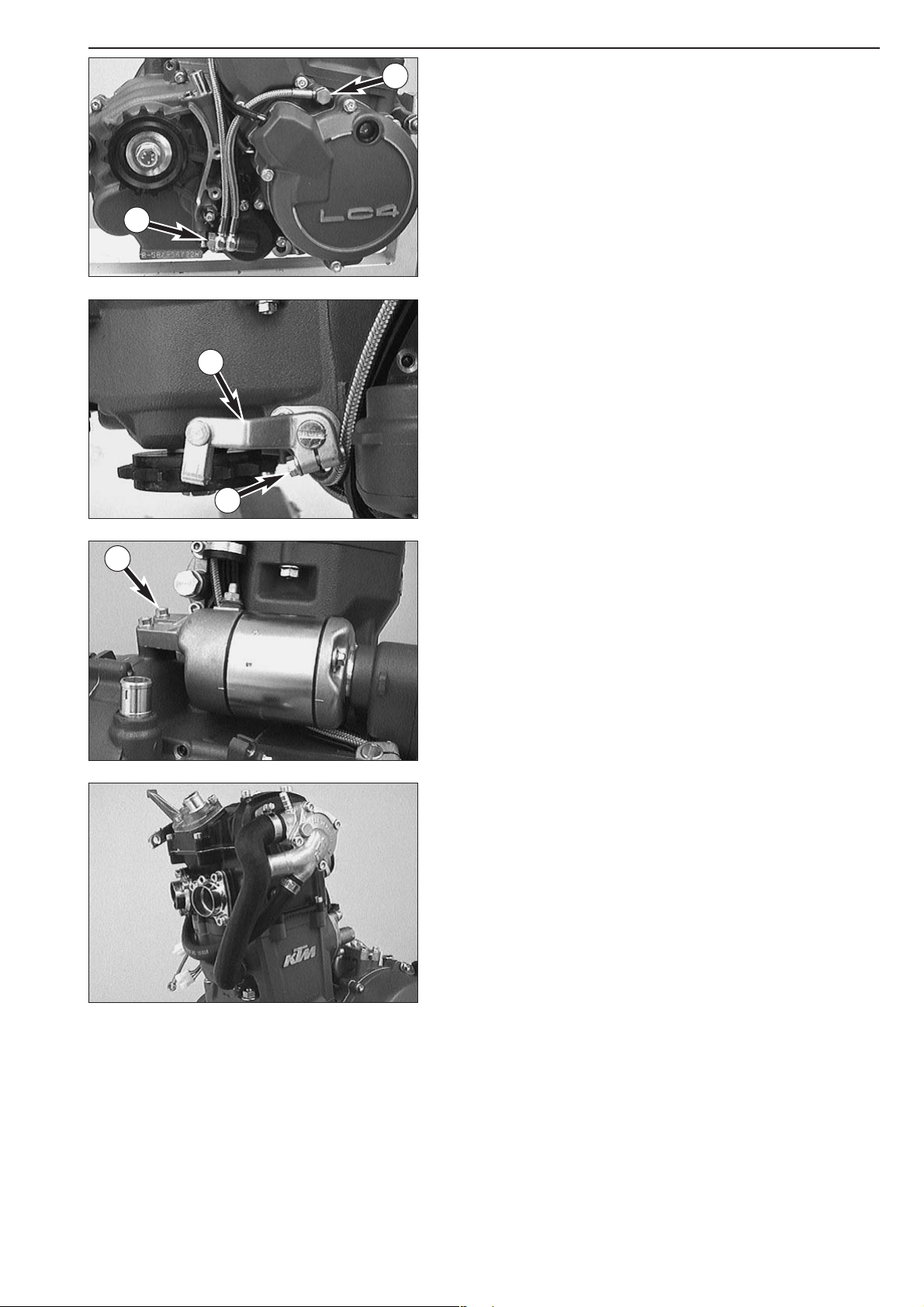
6-20D
Repair manual KTM LC4 Art.-Nr. 3.206.006 -E
Mounting the oil hoses
– Mount the two oil hoses.
–Tighten banjo bolt
1 with 10 Nm and banjo bolt 2 with 15 Nm.
Mounting the clutch release lever
–To mount the clutch release lever 3, turn the clutch release shaft
clockwise as far as stop and fit the release lever as illustrated.
–Tighten clamp bolt
4.
Mounting the electric starter motor
– Slightly oil the O-ring on the flange of the electric starter motor.
–Mount the electric starter motor and fix it with 2 bolts
5.
Mounting the water hoses
– Mount the two water hoses and use the four hose clamps to fasten.
1
2
3
4
5
Page 100
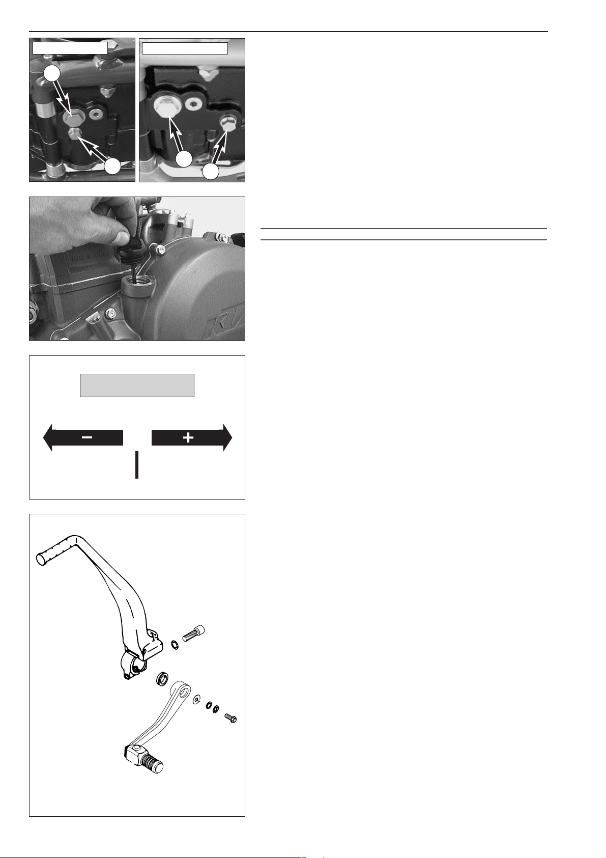
6-21D
Pouring in engine oil
– Mount oil drain plug 1 with seal ring and tighten with 30 Nm.
– Mount the magnetic plug
2 and tighten with 20 Nm.
NOTE: A third plug was installed in the 660 SMC model. Tightening
torque: 20 Nm
– Remove the oil dipstick or the oil filler screw on the clutch cover and
add engine oil (see below for quality and viscosity). Remount the oil
dipstick or the oil filler screw.
!
CAUTION
!
–ONLY USE HIGH
-QUALITY OILS MEETING OR SURPASSING THE QUALITY
REQUIREMENTS OF
JASO T903 MA (FOR SPECIFICATIONS SEE CONTAINERS
).
–INSUFFICIENT OIL OR POOR QUALITY OIL RESULTS IN PREMATURE WEAR OF THE
ENGINE
.
–Y
OU MAY USE EITHER MINERAL OILS OR SYNTHETIC OILS FULFILLING THE ABOVE
CRITERIA
.
Oil capacity (up to model 2002) : 1.40 l
Oil capacity (from model 2003 on) : 1.50 l
Mounting the kickstarter and the shift lever
– Put the kickstarter onto the kickstarter shaft, then mount bolt 3
together with a new Schnorr lock washer 4 and tighten it.
– Put the V- seal ring 5 and the shift lever onto the shifting shaft.
– Mount bolt
6 together with 2 Nordlock discs 7 and washer 8.
– Adjust the stop rubber for the kickstarter so that it rests against the
kickstarter.
NOTE: As soon as the engine is assembled close all openings providing
access to the engine (intake port, exhaust port, water connections,
bleeding openings ...) with appropriate plugs to prevent small parts
from slipping into the interior of the engine during the further
installation process.
3
4
5
8
7
6
1
1
2
up to model 2001
from model 2002 on
2
0°C
32°F
10W/50
5W/40
JASO T903 MA
TEMPERATURE
 Loading...