

KTM 1290 Super Duke R 2019 Owners manual
OWNER'S MANUAL 2019
1290 Super Duke R
Art. no. 3213927en

DEAR KTM CUSTOMER
DEARKTM CUSTOMER
Congratulations on your decision to purchase a KTM motorcycle. You are now the owner of a state-of-the-art
sports motorcycle that will give you enormous pleasure if you service and maintain it properly.
We hope you enjoy riding this motorcycle!
Enter the serial numbers of your vehicle below.
Vehicle identification number ( p. 26) Dealer's stamp
Engine number ( p. 27)
Key number ( p. 27)
The Owner's Manual contained the latest information for this model series at the time of going to print. However,
minor differences due to further developments in design cannot be ruled out completely.
All specifications are non-binding. KTM Sportmotorcycle GmbH specifically reserves the right to modify or delete
technical specifications, prices, colors, forms, materials, services, designs, equipment, etc., without prior notice
and without specifying reasons, to adapt these to local conditions, as well as to stop production of a particular
model without prior notice. KTM accepts no liability for delivery options, deviations from figures and descriptions,
misprints, and other errors. The models portrayed partly contain special equipment that does not belong to the
regular scope of supply.
© 2018 KTM Sportmotorcycle GmbH, Mattighofen Austria
All rights reserved
*3213927en*
3213927en
07/2018

DEAR KTM CUSTOMER
Reproduction, even in part, as well as copying of all kinds, is permitted only with the express written permission
of the copyright owner.
ISO 9001(12 100 6061)
KTM applies quality assurance processes that lead to the highest possible product quality as
defined in the ISO 9001 international quality management standard.
Issued by: TÜV Management Service
KTM Sportmotorcycle GmbH
Stallhofnerstraße 3
5230 Mattighofen, Austria
This document is valid for the following models:
1290 Super Duke R EU (F9903S9, F9903S2)
1290 Super Duke R JP (F9986S2)
2

TABLEOF CONTENTS
1 MEANS OF REPRESENTATION .................... 10
TABLE OF CONTENTS
4 VIEW OF VEHICLE ...................................... 22
1.1 Symbols used .................................. 10
1.2 Formats used................................... 11
2 SAFETY ADVICE.......................................... 12
2.1 Use definition – intended use............ 12
2.2 Misuse............................................ 12
2.3 Safety advice ................................... 12
2.4 Degrees of risk and symbols.............. 13
2.5 Tampering warning........................... 14
2.6 Safe operation ................................. 14
2.7 Protective clothing ........................... 16
2.8 Work rules ....................................... 16
2.9 Environment.................................... 17
2.10 Owner's Manual ............................... 17
3 IMPORTANT NOTES.................................... 18
3.1 Manufacturer and implied warranty.... 18
3.2 Fuel, auxiliary substances................. 18
3.3 Spare parts, accessories ................... 18
3.4 Service ........................................... 19
3.5 Figures ........................................... 19
3.6 Customer service.............................. 19
4.1 View of vehicle, front left (example) ... 22
4.2 View of vehicle, rear right
(example)........................................ 24
5 SERIAL NUMBERS ..................................... 26
5.1 Vehicle identification number............ 26
5.2 Type label ....................................... 26
5.3 Key number..................................... 27
5.4 Engine number ................................ 27
5.5 Fork part number ............................. 28
5.6 Shock absorber article number .......... 28
5.7 Steering damper article number ........ 29
6 CONTROLS................................................. 30
6.1 Clutch lever ..................................... 30
6.2 Hand brake lever.............................. 30
6.3 Throttle grip .................................... 31
6.4 Combination switch, left side ............ 31
6.5 Light switch .................................... 32
6.6 Menu switch.................................... 33
6.7 Turn signal switch............................ 34
6.8 Horn button..................................... 35
6.9 Cruise control system tip switch ........ 35
6.10 Combination switch, right ................. 39
3

TABLE OF CONTENTS
6.11 Hazard warning flasher switch........... 40
6.12 Emergency OFF switch/electric
starter button .................................. 41
6.13 Race‑on tip switch ........................... 42
6.14 Steering lock ................................... 43
6.15 Immobilizer..................................... 44
6.16 Race‑on key .................................... 44
6.17 Opening fuel tank filler cap............... 45
6.18 Closing the fuel tank filler cap........... 47
6.19 Seat lock......................................... 48
6.20 Baggage lugs ................................... 48
6.21 Tool set........................................... 49
6.22 Opening storage compartment........... 49
6.23 Closing storage compartment ............ 50
6.24 Supporting strap .............................. 51
6.25 Passenger foot pegs ......................... 51
6.26 Shift lever ....................................... 52
6.27 Foot brake lever ............................... 53
6.28 Side stand....................................... 53
7 COMBINATION INSTRUMENT ..................... 55
7.1 Combination instrument ................... 55
7.2 Activation and test ........................... 55
7.3 Day-Night mode............................... 56
7.4 Warnings......................................... 57
7.5 Indicator lamps................................ 58
7.6 Display ........................................... 62
7.7 TRACK Display (optional).................. 64
7.8 Shift warning light ........................... 66
7.9 Fuel level display ............................. 67
7.10 Time............................................... 68
7.11 Coolant temperature indicator ........... 68
7.12 Trip distance counter ....................... 69
7.13 Cruise control indicator..................... 69
7.14 Menu.............................................. 70
7.14.1 Favorites..................................... 70
7.14.2 Set Favorites ............................... 71
7.14.3 Trip 1 ......................................... 71
7.14.4 Trip 2 ......................................... 72
7.14.5 Settings ...................................... 73
7.14.6 Language .................................... 74
7.14.7 Unit settings ............................... 74
7.14.8 Fuel Cons.................................... 75
7.14.9 Distance ..................................... 76
7.14.10 Temp.......................................... 77
7.14.11 Pressure ..................................... 78
7.14.12 Service ....................................... 79
7.14.13 Clock/Date .................................. 79
7.14.14 Shift Light .................................. 80
7.14.15 DRL ........................................... 81
7.14.16 Quick Selector 1.......................... 82
7.14.17 Quick Selector 2.......................... 83
4

TABLE OF CONTENTS
7.14.18 Extra Functions ........................... 84
7.14.19 General Info ................................ 85
7.14.20 Warning ...................................... 86
7.14.21 MTC/ABS .................................... 86
7.14.22 Ride Mode .................................. 88
7.15 TPMS ............................................. 89
7.16 Heated grips (optional) ..................... 90
7.17 Heating (optional) ............................ 91
7.18 Quick Shift + (optional) .................... 91
7.19 Track (optional) ............................... 92
7.20 Launch Control (optional) ................. 92
7.21 Anti Wheelie Mode (optional) ............ 93
7.22 Bluetooth®(optional)........................ 94
7.23 KTM MY RIDE (optional) .................. 95
7.24 Pairing (optional) ............................. 96
7.25 Audio (optional)............................... 99
7.26 Telephony (optional)....................... 100
8 ERGONOMICS .......................................... 102
8.1 Handlebar position......................... 102
8.2 Adjusting the handlebar
position ..................................... 102
8.3 Adjusting the basic position of the
clutch lever ................................... 104
8.4 Adjusting the basic position of the
hand brake lever ............................ 105
8.5 Adjusting the basic position of the
foot brake lever .......................... 106
8.6 Setting the step plate of the foot
brake lever .................................... 107
8.7 Checking the basic position of the
shift lever...................................... 108
8.8 Adjusting the basic position of the
shift lever .................................. 109
8.9 Setting the shift lever stub.............. 110
8.10 Adjusting the tilt of the
combination instrument.................. 111
9 PREPARING FOR USE............................... 114
9.1 Advice on preparing for first use ...... 114
9.2 Running in the engine .................... 116
9.3 Loading the vehicle........................ 116
10 RIDING INSTRUCTIONS............................ 119
10.1 Checks and maintenance measures
when preparing for use ................... 119
10.2 Starting the vehicle ........................ 120
10.3 Launch Control (optional) ............... 123
10.4 Starting off.................................... 123
10.5 Starting off with launch control
(optional) ...................................... 124
10.6 Quickshifter+ (optional) .................. 125
5

TABLE OF CONTENTS
10.7 Shifting, riding .............................. 126
10.8 MSR (optional) .............................. 132
10.9 Applying the brakes........................ 133
10.10 Stopping, parking........................... 135
10.11 Transporting.................................. 137
10.12 Refueling ...................................... 139
11 SERVICE SCHEDULE ................................ 141
11.1 Additional information .................... 141
11.2 Required work ............................... 141
11.3 Recommended work ....................... 144
12 SUSPENSION SETTING............................. 145
12.1 Fork/shock absorber ....................... 145
12.2 Adjusting the compression
damping of the fork........................ 145
12.3 Adjusting the rebound damping of
the fork ......................................... 147
12.4 Compression damping of the shock
absorber........................................ 148
12.5 Adjusting the low-speed
compression damping of the shock
absorber........................................ 149
12.6 Adjusting the high-speed
compression damping of the shock
absorber........................................ 150
12.7 Adjusting the rebound damping of
the shock absorber......................... 152
12.8 Measuring the rear wheel
dimension unloaded ....................... 153
12.9 Checking the static sag of the
shock absorber .............................. 154
12.10 Adjusting the spring preload of the
shock absorber ........................... 155
13 SERVICE WORK ON THE CHASSIS............. 158
13.1 Lifting the motorcycle with the rear
lifting gear .................................... 158
13.2 Removing the rear of motorcycle
from the lifting gear ....................... 158
13.3 Lifting the motorcycle with the
front lifting gear............................. 159
13.4 Taking the motorcycle off the front
lifting gear .................................... 160
13.5 Raising the motorcycle with the
work stand (inserted)...................... 161
13.6 Removing the motorcycle from the
work stand (inserted)...................... 163
13.7 Cleaning the dust boots of the fork
legs ........................................... 165
13.8 Removing the passenger seat .......... 166
13.9 Mounting the passenger seat ........... 166
6
TABLE OF CONTENTS
13.10 Removing the front rider's seat........ 167
13.11 Mounting the front rider's seat......... 168
13.12 Mounting the helmet lock on the
vehicle.......................................... 168
13.13 Removing the main silencer ........ 170
13.14 Installing the main silencer ......... 171
13.15 Checking the chain for dirt.............. 173
13.16 Cleaning the chain ......................... 173
13.17 Checking the chain tension ............. 175
13.18 Adjusting the chain tension............. 177
13.19 Checking the chain, rear sprocket,
engine sprocket, and chain guide .... 178
13.20 Checking/correcting the fluid level
of the hydraulic clutch.................... 183
14 BRAKE SYSTEM ....................................... 186
14.1 Anti-lock braking system (ABS) ....... 186
14.2 Checking the brake discs ................ 189
14.3 Checking the front brake fluid
level ............................................. 191
14.4 Adding front brake fluid .............. 192
14.5 Checking the front brake linings ...... 194
14.6 Checking the rear brake fluid
level ............................................. 196
14.7 Adding rear brake fluid ............... 197
14.8 Checking the brake linings of the
rear brake...................................... 199
15 WHEELS, TIRES ....................................... 201
15.1 Removing the front wheel ............ 201
15.2 Installing the front wheel ............ 203
15.3 Removing the rear wheel ............. 206
15.4 Installing the rear wheel .............. 208
15.5 Checking the tire condition ............. 211
15.6 Checking tire pressure .................... 213
15.7 Using tire repair spray .................... 215
16 ELECTRICAL SYSTEM ............................... 216
16.1 Daytime running light (DRL)............. 216
16.2 Removing the 12-V battery .......... 217
16.3 Installing the 12-V battery ........... 219
16.4 Charging the 12-V battery ........... 222
16.5 Changing the Race-on key battery.... 228
16.6 Changing the main fuse.................. 229
16.7 Changing the fuses in the fuse
box............................................... 233
16.8 Checking the headlight setting ........ 238
16.9 Adjusting the headlight range.......... 239
16.10 Connecting the USB cable .............. 240
16.11 Disconnecting the USB cable .......... 242
16.12 Diagnostics connector .................... 244
7

TABLE OF CONTENTS
16.13 Front ACC1 and ACC2 .................... 244
16.14 ACC1 and ACC2 rear ...................... 245
17 COOLING SYSTEM .................................... 246
17.1 Checking the coolant level in the
compensating tank......................... 246
17.2 Correcting the coolant level in the
compensating tank......................... 248
18 ENGINE TUNING ...................................... 251
18.1 Ride Mode .................................... 251
18.2 Motorcycle traction control (MTC) .... 252
18.3 Slip adjustment (optional)............... 253
18.4 Throttle Response (optional) ........... 254
19 SERVICE WORK ON THE ENGINE .............. 255
19.1 Checking the engine oil level........... 255
19.2 Changing the engine oil and oil
filter, cleaning the oil screens ...... 256
19.3 Adding engine oil........................... 263
20 CLEANING, CARE ..................................... 266
20.1 Cleaning the motorcycle ................. 266
20.2 Checks and maintenance steps for
winter operation............................. 269
21 STORAGE................................................. 271
21.1 Storage ......................................... 271
21.2 Preparing for use after storage......... 273
22 TROUBLESHOOTING ................................ 274
23 TECHNICAL DATA..................................... 278
23.1 Engine .......................................... 278
23.2 Engine tightening torques ............... 280
23.3 Capacities ..................................... 285
23.3.1 Engine oil ................................. 285
23.3.2 Coolant..................................... 285
23.3.3 Fuel ......................................... 285
23.4 Chassis ......................................... 286
23.5 Electrical system............................ 287
23.6 Tires ............................................. 288
23.7 Fork.............................................. 288
23.8 Shock absorber.............................. 289
23.9 Chassis tightening torques .............. 291
24 DECLARATIONS OF CONFORMITY ............. 298
24.1 Declarations of conformity .............. 298
24.2 Country-specific declarations of
conformity..................................... 302
25 SUBSTANCES .......................................... 303
8

26 AUXILIARY SUBSTANCES ......................... 307
27 STANDARDS ............................................ 309
28 INDEX OF SPECIAL TERMS ....................... 310
29 LIST OF ABBREVIATIONS.......................... 312
30 LIST OF SYMBOLS.................................... 313
30.1 Red symbols.................................. 313
30.2 Yellow and orange symbols.............. 313
30.3 Green and blue symbols.................. 314
INDEX ............................................................. 315
TABLE OF CONTENTS
9
1 MEANS OF REPRESENTATION
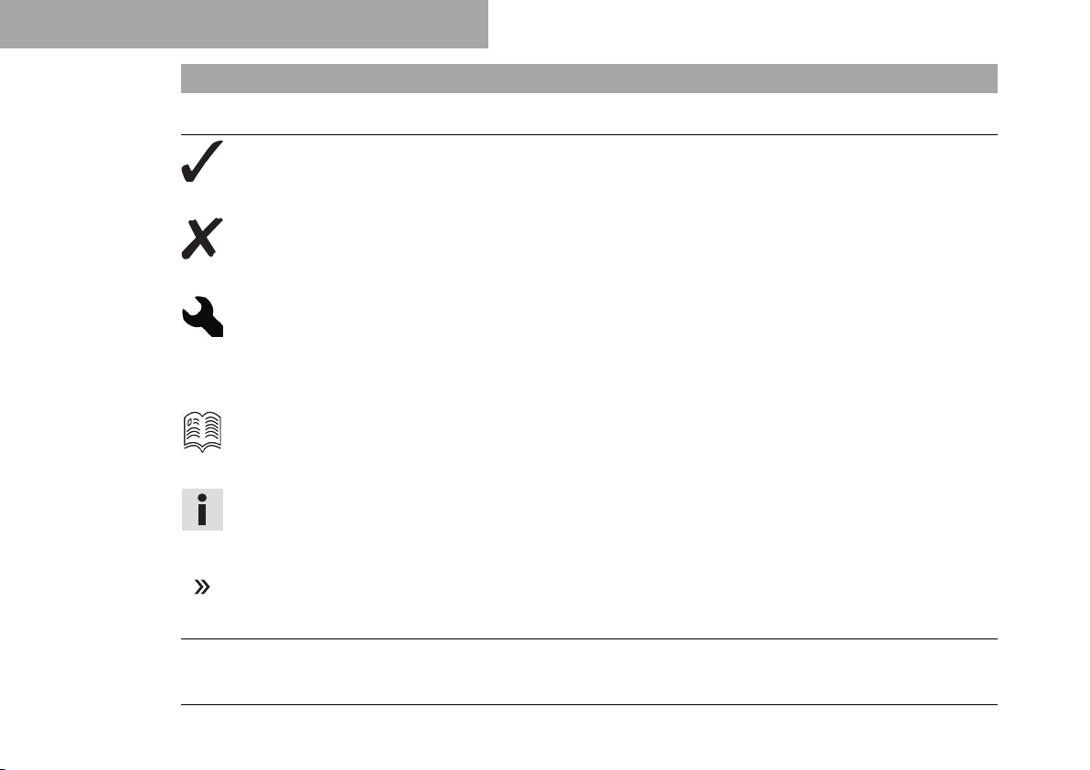
1.1 Symbols used
The meaning of specific symbols is described below.
Indicates an expected reaction (e.g. of a work step or a function).
Indicates an unexpected reaction (e.g. of a work step or a function).
All work marked with this symbol requires specialist knowledge and technical understanding.
In the interest of your own safety, have these jobs performed by an authorized KTM workshop!
Your motorcycle will be optimally cared for there by specially trained experts using the auxiliary
tools required.
Indicates a page reference (more information is provided on the specified page).
Indicates information with more details or tips.
10
Indicates the result of a testing step.

MEANS OF REPRESENTATION 1
Indicates a voltage measurement.
Indicates a current measurement.
Indicates the end of an activity, including potential rework.
1.2 Formats used
The typographical formats used in this document are explained below.
Proprietary name Indicates a proprietary name.
®
Name
Brand™ Indicates a brand available on the open market.
Underlined terms Refer to technical details of the vehicle or indicate technical terms, which
Indicates a protected name.
are explained in the glossary.
11

2 SAFETY ADVICE
2.1 Use definition – intended use
The vehicle is designed and constructed to withstand the usual demands of regular traffic and use on race
courses. This vehicle is not suitable for offroad use.
Info
This vehicle is only authorized for operation on public roads in its homologated version.
2.2 Misuse
The vehicle must only be used as intended.
Dangers can arise for people, property and the environment through use not as intended.
Any use of the vehicle beyond the intended and defined use constitutes misuse.
Misuse also includes the use of operating and auxiliary fluids which do not meet the required specification for the
respective use.
2.3 Safety advice
A number of safety instructions need to be followed to operate the product described safely. Therefore read this
instruction and all further instructions included carefully. The safety instructions are highlighted in the text and
are referred to at the relevant passages.
12
SAFETY ADVICE 2
Info
Various information and warning labels are attached in prominent locations on the product described. Do
not remove any information or warning labels. If they are missing, you or others may not recognize dangers
and may therefore be injured.
2.4 Degrees of risk and symbols
Danger
Identifies a danger that will immediately and invariably lead to fatal or serious permanent injury if the
appropriate measures are not taken.
Warning
Identifies a danger that is likely to lead to fatal or serious injury if the appropriate measures are not
taken.
Caution
Identifies a danger that may lead to minor injuries if the appropriate measures are not taken.
Note
Identifies a danger that will lead to considerable machine and material damage if the appropriate measures are
not taken.
Note
Indicates a danger that will lead to environmental damage if the appropriate measures are not taken.
13

2 SAFETY ADVICE
2.5 Tampering warning
Tampering with the noise control system is prohibited. Federal law prohibits the following acts or the causing
thereof:
1 The removal or rendering inoperative by any person other than for purposes of servicing, repair, or replace-
ment, of any device or element of design incorporated into any new vehicle for the purpose of noise control
prior to its sale or delivery to the ultimate purchaser or while it is in use, or
2 the use of the vehicle after such device or element of design has been removed or rendered inoperative by any
person.
Among those acts presumed to constitute tampering are the acts listed below:
1 Removal or puncturing of the main silencers, baffles, header pipes or any other components which conduct
exhaust gases.
2 Removal or puncturing of parts of the intake system.
3 Lack of proper maintenance.
4 Replacing moving parts of the vehicle, or parts of the exhaust system or intake system, with parts other than
those specified by the manufacturer.
2.6 Safe operation
Danger
Danger of accidents A rider who is not fit to ride poses a danger to him or herself and others.
– Do not operate the vehicle if you are not fit to ride due to alcohol, drugs or medication.
– Do not operate the vehicle if you are physically or mentally impaired.
14
SAFETY ADVICE 2
Danger
Danger of poisoning Exhaust gases are toxic and inhaling them may result in unconsciousness and death.
– Always make sure there is sufficient ventilation when running the engine.
– Use effective exhaust extraction when starting or running the engine in an enclosed space.
Warning
Danger of burns Some vehicle components become very hot when the vehicle is operated.
– Do not touch any parts such as the exhaust system, radiator, engine, shock absorber, or brake system
before the vehicle parts have cooled down.
– Let the vehicle parts cool down before you perform any work on the vehicle.
Only operate the vehicle when it is in perfect technical condition, in accordance with its intended use, and in a
safe and environmentally compatible manner.
The vehicle should only be used by trained persons. An appropriate driver's license is needed to ride the vehicle
on public roads.
Have malfunctions that impair safety promptly eliminated by an authorized KTM workshop.
Adhere to the information and warning labels on the vehicle.
15

2 SAFETY ADVICE
2.7 Protective clothing
Warning
Risk of injury Missing or poor protective clothing presents an increased safety risk.
– Wear appropriate protective clothing such as helmet, boots, gloves as well as trousers and a jacket
with protectors on all rides.
– Always wear protective clothing that is in good condition and meets the legal regulations.
In the interest of your own safety, KTM recommends that you only operate the vehicle while wearing protective
clothing.
2.8 Work rules
Special tools are necessary for certain tasks. The tools are not a component of the vehicle, but can be ordered
using the number in parentheses. Example: bearing puller (15112017000)
During assembly, use new parts to replace parts which cannot be reused (e.g. self-locking screws and nuts, seals,
sealing rings, O-rings, pins, and lock washers).
In the case of certain screws, a screw adhesive (e.g. Loctite®) is required. Observe the manufacturer's instructions.
After disassembly, clean the parts that are to be reused and check them for damage and wear. Change damaged
or worn parts.
After completing a repair or service work, check the operating safety of the vehicle.
16

SAFETY ADVICE 2
2.9 Environment
If you use your motorcycle responsibly, you can ensure that problems and conflicts do not occur. To protect the
future of the motorcycle sport, make sure that you use your motorcycle legally, display environmental consciousness, and respect the rights of others.
When disposing of used oil, other operating and auxiliary fluids, and used components, comply with the laws and
regulations of the respective country.
Because motorcycles are not subject to the EU regulations governing the disposal of used vehicles, there are no
legal regulations that pertain to the disposal of an end-of-life motorcycle. Your authorized KTM dealer will be glad
to advise you.
2.10 Owner's Manual
It is important that you read this Owner's Manual carefully and completely before making your first trip. The Owner's Manual contains useful information and many tips on how to operate, handle, and service your motorcycle.
Only then will you find out how to customize the vehicle ideally for your own use and how you can protect yourself
from injury.
Keep the Owner's Manual in an accessible place to enable you to refer to it as needed.
If you would like to know more about the vehicle or have questions on the material you read, please contact an
authorized KTM dealer.
The Owner's Manual is an important component of the vehicle and must be handed over to the new owner if the
vehicle is sold.
The Owner's Manual is also available for download from your authorized KTM dealer and on the KTM website.
International KTM Website: http://www.ktm.com
17

3 IMPORTANT NOTES
3.1 Manufacturer and implied warranty
The work specified in the service schedule may only be performed in an authorized KTM workshop and must be
recorded in both the Service & Warranty Booklet and in the KTM Dealer.net, otherwise any warranty coverage will
become void. Damage or secondary damage caused by tampering with and/or conversions on the vehicle is not
covered by the manufacturer warranty.
Additional information on the manufacturer or manufacturer warranty and the procedures involved can be found
in the Service & Warranty Booklet.
3.2 Fuel, auxiliary substances
Note
Environmental hazard Improper handling of fuel is a danger to the environment.
– Do not allow fuel to enter the groundwater, the soil, or the sewage system.
Use fuels and auxiliary substances in accordance with the Owner's Manual and specification.
3.3 Spare parts, accessories
For your own safety, only use spare parts and accessory products that are approved and/or recommended by KTM
and have them installed by an authorized KTM workshop. KTM accepts no liability for other products and any
resulting damage or loss.
Certain spare parts and accessory products are specified in parentheses in the descriptions. Your authorized KTM
dealer will be glad to advise you.
18

IMPORTANT NOTES 3
The current KTM PowerParts for your vehicle can be found on the KTM website.
International KTM Website: http://www.ktm.com
3.4 Service
A prerequisite for perfect operation and prevention of premature wear is that the service, care, and tuning work
on the engine and chassis is properly carried out as described in the Owner's Manual. Incorrect adjustment and
tuning of the engine and chassis can lead to damage and breakage of components.
Use of the vehicle under difficult conditions, such in rain, high heat or with a heavy load, can lead to considerably more rapid wear of components such as the drive train, brake system, or suspension components. For this
reason, it may be necessary to inspect or replace parts before the next scheduled service.
It is imperative that you adhere to the stipulated run-in times and service intervals. If you observe these exactly,
you will ensure a much longer service life for your motorcycle.
3.5 Figures
The figures contained in the manual may depict special equipment.
In the interest of clarity, some components may be shown disassembled or may not be shown at all. It is not
always necessary to disassemble the component to perform the activity in question. Please follow the instructions
in the text.
3.6 Customer service
Your authorized KTM dealer will be happy to answer any questions you may have on your vehicle and KTM.
19

3 IMPORTANT NOTES
A list of authorized KTM dealers can be found on the KTM website.
International KTM Website: http://www.ktm.com
20

IMPORTANT NOTES 3
21
4 VIEW OF VEHICLE
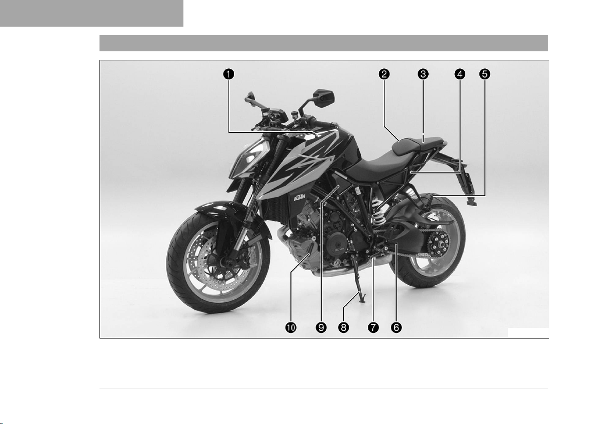
4.1 View of vehicle, front left (example)
22
S03091-10

Clutch lever ( p. 30)
1
Supporting strap ( p. 51)
2
Tool set ( p. 49)
3
Seat lock ( p. 48)
4
Passenger foot pegs ( p. 51)
5
Rider footrests
6
Shift lever ( p. 52)
7
Side stand ( p. 53)
8
Cooling system compensating tank
9
Engine oil level viewer
bk
VIEW OF VEHICLE 4
23
4 VIEW OF VEHICLE
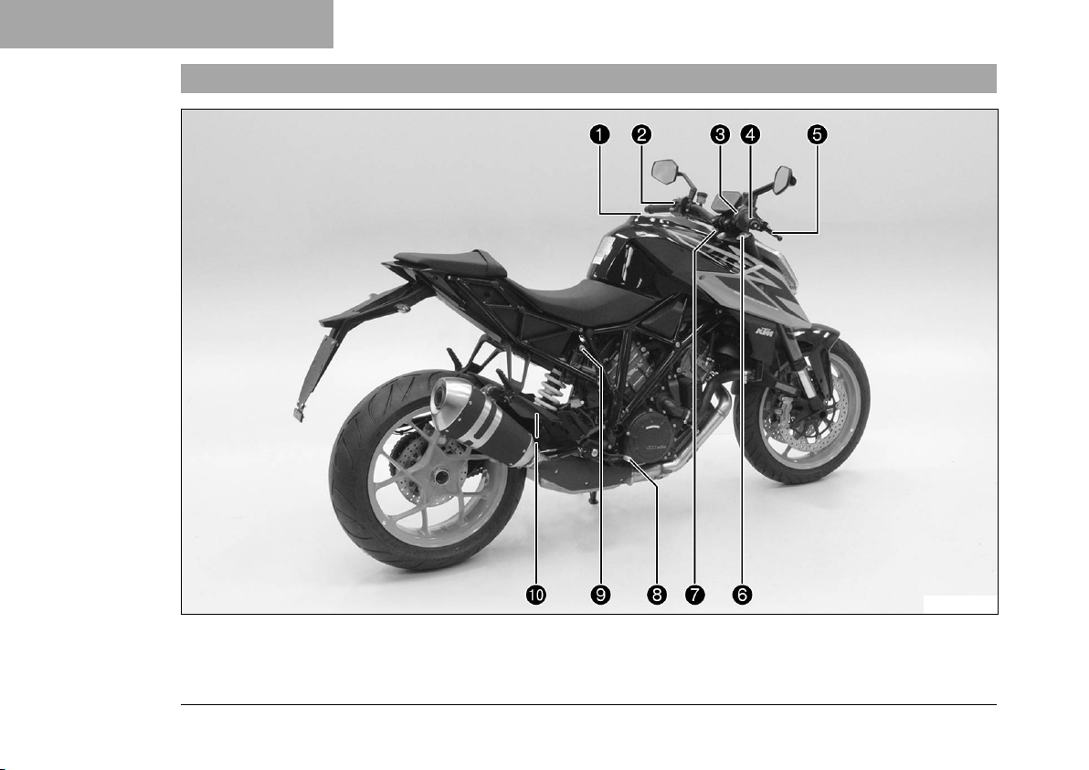
4.2 View of vehicle, rear right (example)
24
S03092-10

Fuel tank filler cap
1
Combination switch, left side ( p. 31)
2
Emergency OFF switch/electric starter button ( p. 41)
3
Race‑on tip switch ( p. 42)
3
Hazard warning flasher switch ( p. 40)
3
Throttle grip ( p. 31)
4
Hand brake lever ( p. 30)
5
Fork compression adjuster
6
Fork rebound adjustment
7
Foot brake lever ( p. 53)
8
Compression damping of the shock absorber ( p. 148)
9
Shock absorber rebound damping
bk
VIEW OF VEHICLE 4
25
5 SERIAL NUMBERS
0011
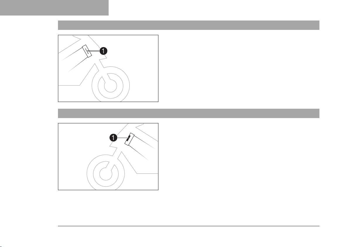
5.1 Vehicle identification number
5.2 Type label
The vehicle identification number1is stamped on the right side
of the steering head.
The vehicle identification number is also shown on the type label.
402324-10
The type label1is located on the steering head.
402302-10
26
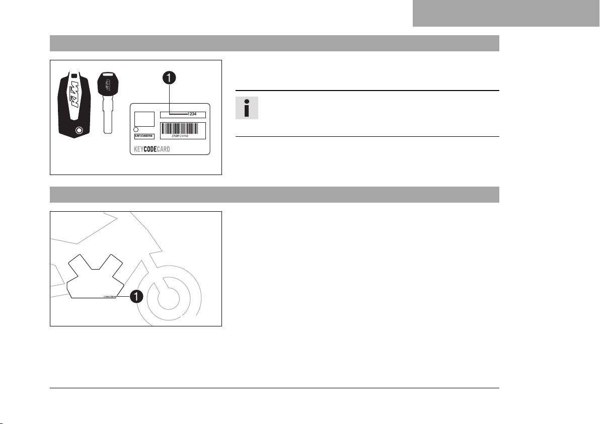
5.3 Key number
5.4 Engine number
SERIAL NUMBERS 5
The key number Code number1can be found on
the KEYCODECARD.
Info
You need the key number to order a spare key. Keep
the KEYCODECARD in a safe place.
F01249-10
The engine number1is stamped on the right side of the engine.
402296-10
27
5 SERIAL NUMBERS
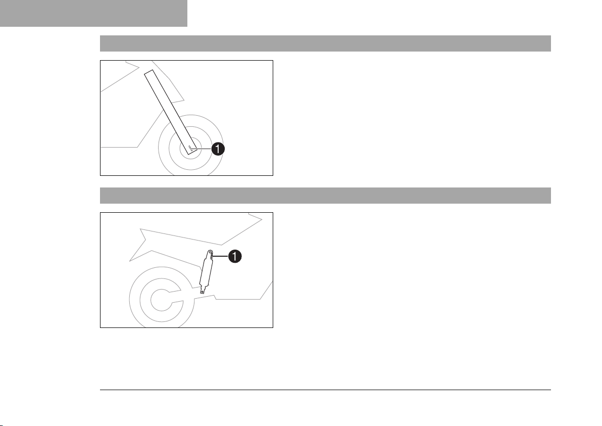
5.5 Fork part number
5.6 Shock absorber article number
The fork part number1is stamped on the inside of the axle
clamp.
402295-10
The shock absorber article number1is stamped on the top of
the shock absorber above the adjusting ring towards the engine
side.
28
402798-10
 Loading...